Embed Size (px)
Citation preview
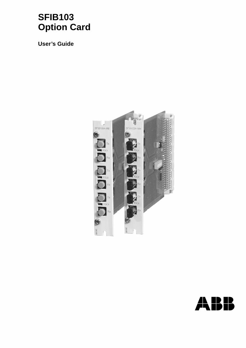
SFIB103Option Card
User’s Guide

3
Option card
User’s guide
SFIB1031MRS 751296-MUMIssued: 07.11.2000Version: A/07.11.00Checked: P.L.Approved: T.M.
We reserve the right to change data without prior notice.
Contents
1. Introduction ...............................................................................4
2. Safety information .....................................................................5
3. Applications ...............................................................................6
4. Functions ...................................................................................74.1. General .........................................................................................7
5. Mechanical and electrical design ............................................85.1. Block diagram ...............................................................................8
5.2. Mechanical structure .....................................................................8
6. Interfaces .................................................................................106.1. General .......................................................................................10
6.2. Fibre-optic interface ....................................................................10
6.3. LED interface ..............................................................................10
7. Installation, configuration and programming .......................117.1. Mechanical installation ................................................................11
7.2. Configuration of function mode ...................................................11
7.2.1. DIP switch settings of SFIB103 card ................................12
8. Technical data .........................................................................14
9. Maintenance and service ........................................................159.1. Self-diagnosis ..............................................................................15
9.2. Service and spare parts ..............................................................15
10.Ordering information .............................................................16
11.Index ........................................................................................17
12.Customer feedback ................................................................18

4
1MRS 751296-MUMOption card
User’s guide
SFIB103
1. Introduction
The fibre-optic SFIB103 Option card is designed for use in the RER 125. The RER 125 unit including SFIB103 Option card provides a fibre-optic star connection point for interconnection of devices using the IEC 60870-5-103 protocol.
The SFIB103 Option card contains three pairs of fibre-optic interconnections for bay-level devices, other RER 125 units or higher level devices, e.g. MicroSCADA.
There are two different types of option cards: with ST or snap-in tranceivers. These transceiver types are fixed and can be chosen upon ordering. For ordering information, refer to page 16.
1MRS 751296-MUM Option card
User’s guide
SFIB103
5
2. Safety information
Electrostatic sensitive devices. ESD must be avoided during installation and while components remain detached.
Dangerous voltages can occur on the connectors, even though the auxiliary voltage is disconnected.
National and local electrical safety regulations must always be followed.
Only a competent electrician is allowed to carry out the electrical installation.
�
�
�
6
1MRS 751296-MUMOption card
User’s guide
SFIB103
3. Applications
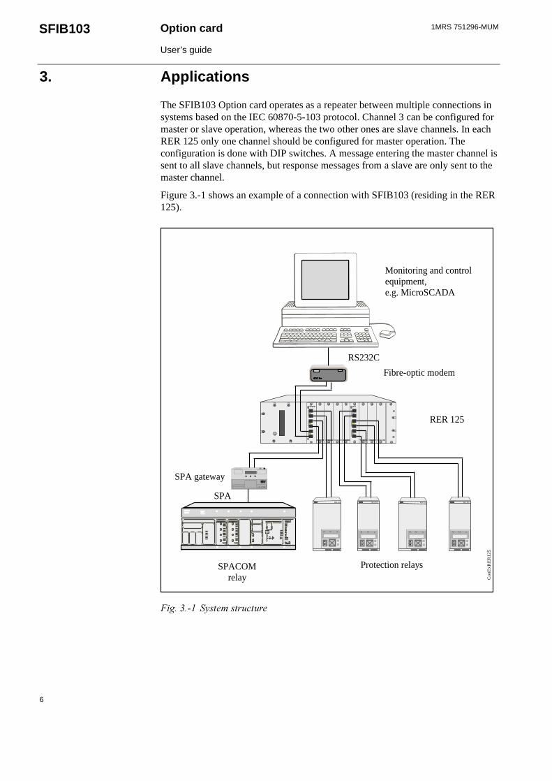
The SFIB103 Option card operates as a repeater between multiple connections in systems based on the IEC 60870-5-103 protocol. Channel 3 can be configured for master or slave operation, whereas the two other ones are slave channels. In each RER 125 only one channel should be configured for master operation. The configuration is done with DIP switches. A message entering the master channel is sent to all slave channels, but response messages from a slave are only sent to the master channel.
Figure 3.-1 shows an example of a connection with SFIB103 (residing in the RER 125).
��������� �� ����������
REX 52xREX 52x REJ 525 REJ 525
SPA-ZC 101
Fibre-optic modem
RER 125
Monitoring and controlequipment,e.g. MicroSCADA
RS232C
SPA gateway
SPA
SPACOMrelay C
onE
xRE
R12
5
Protection relays
1MRS 751296-MUM Option card
User’s guide
SFIB103
7
4. Functions
4.1. General
The SFIB103 Option card connects to an IEC 60870-5-103 network via three fibre-optic transmitter/receiver pairs and through the open collector buses on the RER 125 unit’s mother board. The RER 125 unit including SFIB103 Option card provides a star connection point for interconnection of devices using the IEC 60870-5-103 protocol.
The line idle state of each channel (“light on” or “light off”) is configurable with the DIP switches located on the SFIB103 board. The IEC 60870-5-103 standard defines “light on” as the line idle state.
If a fault occurs on a channel, it is automatically disconnected after 50 ms.
8
1MRS 751296-MUMOption card
User’s guide
SFIB103
5. Mechanical and electrical design
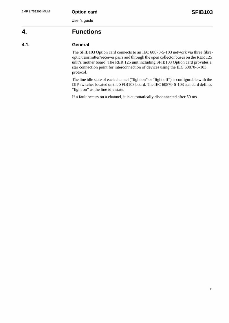
5.1. Block diagram
����������� ������������������� ������������������������� ��� � � ��� ���� ������ �������� �������������
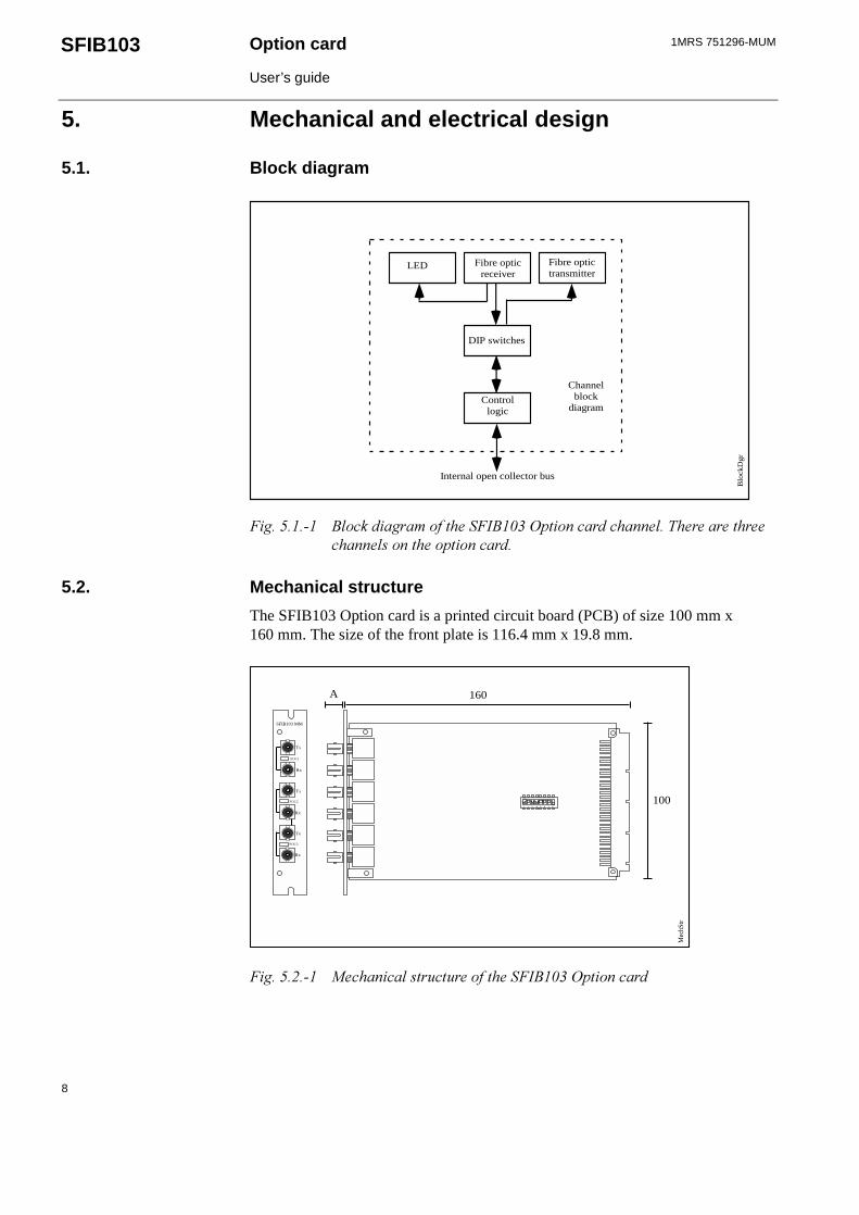
5.2. Mechanical structure
The SFIB103 Option card is a printed circuit board (PCB) of size 100 mm x 160 mm. The size of the front plate is 116.4 mm x 19.8 mm.
�������!��� " ����������������� ������ �������������������
Fibre opticreceiver
Fibre optictransmitter
LED
DIP switches
Controllogic
Internal open collector bus
Channelblock
diagram
Blo
ckD
gr
SFIB103 MM
Tx
Tx
Tx
Rx
Rx
Rx
FOC1
FOC2
FOC3
Mec
hStr
ON
1 2 3 4 5 6 7 8
A 160
100

1MRS 751296-MUM Option card
User’s guide
SFIB103
9
The length of the PCB depends on the tranceiver type of the option card. The table below presents the additional measurements according to the tranceiver types.
Table 5.2.-1 Fibre-optic connector length
Type A
ST 11.0 mmSnap-in 0
10
1MRS 751296-MUMOption card
User’s guide
SFIB103
6. Interfaces
6.1. General
The SFIB103 Option card has the following interfaces:
• 64-pin E1 card connector for the connection to the mother board of the IEC 103 Star Coupler
• 3 fibre-optic transceiver pairs
• LED interface for indicating traffic on the bus or for error indication
• DIP switches, see “DIP switch settings of SFIB103 card” on page 12
Fibre-optic cables for use with the SFIB103 and the RER 125 are ordered separately.
6.2. Fibre-optic interface
The SFIB103 Option card is equipped with three fibre-optic transceiver pairs. These fibre-optic pairs can be of two different types, ST and snap-in type, and they are to be defined by the user in the order. Refer to the RER 125 User’s Guide (1MRS 751295-MUM) for more details about the fibre-optic interface. For ordering information, see page 16.
6.3. LED interface
The SFIB103 card contains a LED for each fibre-optic channel. The LEDs indicate fault states or traffic on the channel. When a message is being received, the LED flashes. If the SFIB103 channel is configured “light on” as the line idle state, a continously lit LED indicates that the channel is temporarily disconnected. This will happen, when the slave device connected to the channel is not sending out any light.
In the contrary case, when the line idle state for the SFIB 103 channel is “light off” and the slave device connected to the channel sends a constant light, the channel is disconnected and the LED is continuously lit. For further information, see chapter “Self-diagnosis” on page 15.
1MRS 751296-MUM Option card
User’s guide
SFIB103
11
7. Installation, configuration and programming
7.1. Mechanical installation
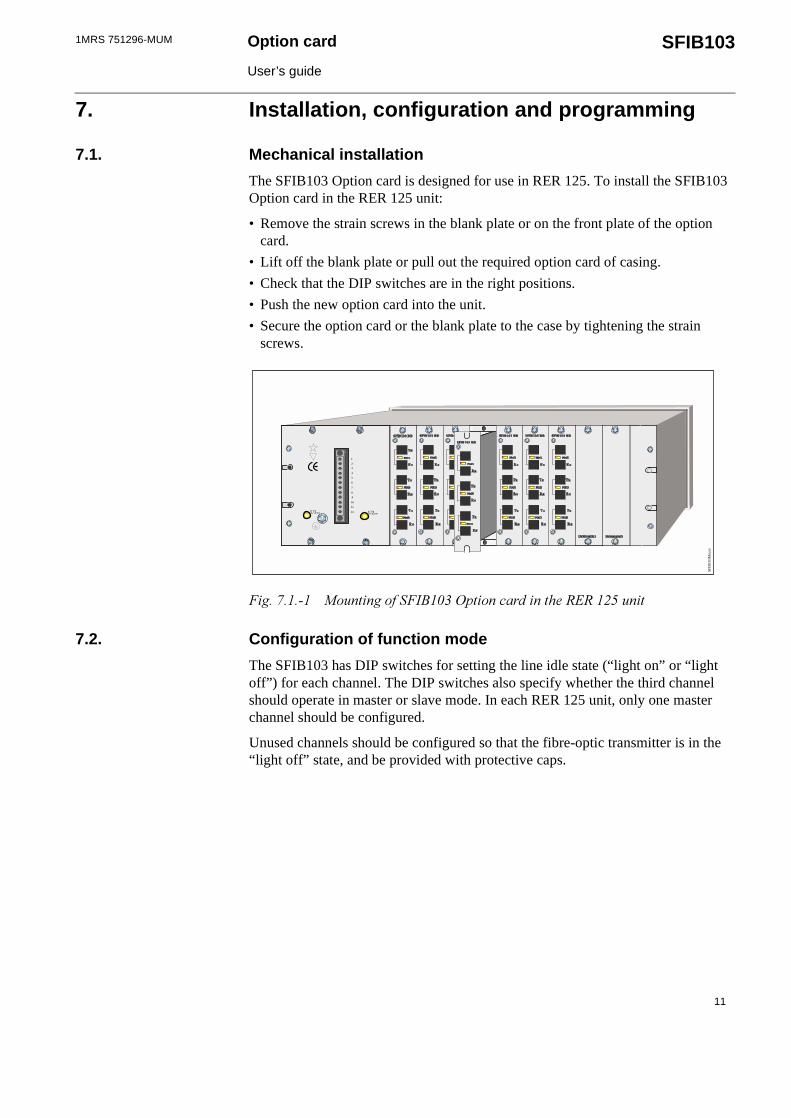
The SFIB103 Option card is designed for use in RER 125. To install the SFIB103 Option card in the RER 125 unit:
• Remove the strain screws in the blank plate or on the front plate of the option card.
• Lift off the blank plate or pull out the required option card of casing.
• Check that the DIP switches are in the right positions.
• Push the new option card into the unit.
• Secure the option card or the blank plate to the case by tightening the strain screws.
�����#����� "����������������������������������� �$%$��!������
7.2. Configuration of function mode
The SFIB103 has DIP switches for setting the line idle state (“light on” or “light off”) for each channel. The DIP switches also specify whether the third channel should operate in master or slave mode. In each RER 125 unit, only one master channel should be configured.
Unused channels should be configured so that the fibre-optic transmitter is in the “light off” state, and be provided with protective caps.
U1aux U2aux
1
2
8
5
6
3
7
10
11
9
12
4
SFIB
103M
ount
12
1MRS 751296-MUMOption card
User’s guide
SFIB103
7.2.1. DIP switch settings of SFIB103 card
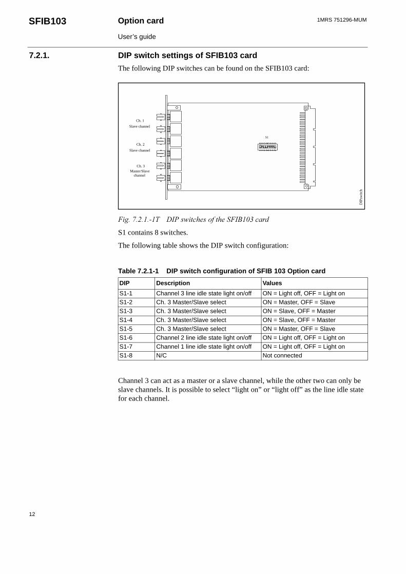
The following DIP switches can be found on the SFIB103 card:
�����#�!����� &�'��(���� ������� ������������
S1 contains 8 switches.
The following table shows the DIP switch configuration:
Channel 3 can act as a master or a slave channel, while the other two can only be slave channels. It is possible to select “light on” or “light off” as the line idle state for each channel.
Table 7.2.1-1 DIP switch configuration of SFIB 103 Option card
DIP Description Values
S1-1 Channel 3 line idle state light on/off ON = Light off, OFF = Light onS1-2 Ch. 3 Master/Slave select ON = Master, OFF = SlaveS1-3 Ch. 3 Master/Slave select ON = Slave, OFF = Master
S1-4 Ch. 3 Master/Slave select ON = Slave, OFF = MasterS1-5 Ch. 3 Master/Slave select ON = Master, OFF = SlaveS1-6 Channel 2 line idle state light on/off ON = Light off, OFF = Light on
S1-7 Channel 1 line idle state light on/off ON = Light off, OFF = Light onS1-8 N/C Not connected
DIP
switc
h
ON
1 2 3 4 5 6 7 8
S1
Ch. 1
Ch. 2
Ch. 3
Slave channel
Master/Slave channel
Slave channel
1MRS 751296-MUM Option card
User’s guide
SFIB103
13
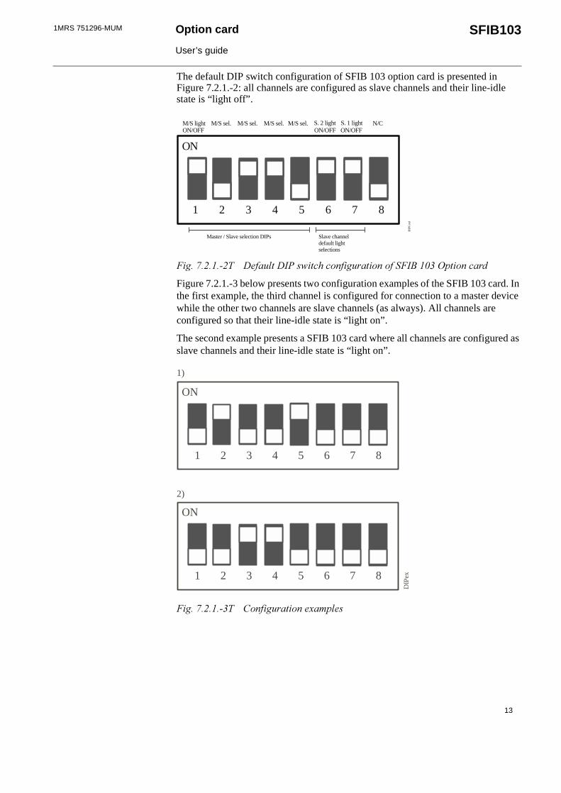
The default DIP switch configuration of SFIB 103 option card is presented in Figure 7.2.1.-2: all channels are configured as slave channels and their line-idle state is “light off”.
�����#�!����! & ������&�'��(�����������������������������������������
Figure 7.2.1.-3 below presents two configuration examples of the SFIB 103 card. In the first example, the third channel is configured for connection to a master device while the other two channels are slave channels (as always). All channels are configured so that their line-idle state is “light on”.
The second example presents a SFIB 103 card where all channels are configured as slave channels and their line-idle state is “light on”.
�����#�!����� )������������� *���� �
M/S lightON/OFF
M/S sel. S. 1 lightON/OFFS. 2 light
ON/OFF N/CM/S sel. M/S sel. M/S sel.
Master / Slave selection DIPs Slave channeldefault lightselections
1 2 3 4 5 6 7 8
ON
DIP
Con
f
1 2 3 4 5 6 7 8
ON
1)
1 2 3 4 5 6 7 8
ON
2)
DIP
ex

14
1MRS 751296-MUMOption card
User’s guide
SFIB103
8. Technical data
Table 8.-1 Interfaces
Fibre-optic interface • glass fibre with ST type connectors• plastic fibre with snap-in type connectors
Communication speed 9600 / 19200 bps
Option card to mother board 64-pin E1 connector
Table 8.-2 Power source
From the mother board interconnection +8 V dc
Table 8.-3 Power consumption
SFIB103A-MM <1.8 W
SFIB103A-BB <1.8 W
Table 8.-4 Size
100 mm x 160 mm (E1 card.) See Figure 5.2.-1.116.4 mm x 19.8 mm (front plate)
Table 8.-5 Disturbance tests
High frequency interference test according to IEC 60255-22-1• common mode 2.5 kV, 1 MHz
• differential mode 1.0 kV, 1 MHzFast transient test according to IEC 61000-4-4 and IEC 60255-22-4, class IV
4 kV
Electrostatic discharge test according to IEC 61000-4-2 and IEC 60255-22-2, class III• contact discharge 6 kV• air discharge 8 kV
Table 8.-6 Environmental conditions
Specified ambient service temperature range -10...+55°C
Transport and storage temperature range -40...+70°C
Table 8.-7 Climatic environmental tests
Dry heat test according to IEC 60068-2-2 +55°C
Dry cold test according to IEC 60068-2-1 -10°C
Damp heat test according to IEC 60068-2-30 RH = 93%, 55°C, 6 cycles
1MRS 751296-MUM Option card
User’s guide
SFIB103
15
9. Maintenance and service
9.1. Self-diagnosis
The LED of each fibre-optic channel can be used for diagnosing fault states.
A rapidly flashing LED of a channel indicates that the channel is receiving data. If the LED is off, there is no traffic.
If the channel LED is continuously on, the reason may be:
• If nothing is connected to the channel, the channel’s line idle state is probably configured “light on”. The channel will automatically be disconnected from the mother board until a slave device with the line idle state “light on” is connected to RER 125.
• If the line idle state of a channel is configured to be “light off”, the continuously lit LED indicates that the slave device sends light continuously and the channel will be disconnected from the RER 125 unit. When a channel is not used, configure the line idle state to “light off”.
• If a slave device is connected to the channel, the setting of the line idle state of the channel can be wrong, or there may be a fault in this device. First, check the DIP switches of the SFIB103, and correct their state if necessary. If there is a problem with the slave device, replace it or correct the problem.
If you are having problems with the communication, check that the DIP switches are properly set. Refer to “Configuration of function mode” on page 11.
9.2. Service and spare parts
If a fault occurs in the SFIB103 Option card, then the normal service procedure is to replace the faulty option card with a new one. For ordering information, see page 16. Please, send the faulty part to the manufacturer.
Power must be set off during maintenance and service of the SFIB 103 and the RER 125.�
16
1MRS 751296-MUMOption card
User’s guide
SFIB103
10. Ordering information
When ordering, please state the following:
1. Quantity required
2. Type of fibre-optic transceivers
Option cards
Fibre-optics
Ordering example
Ordering 4 pcs. of SFIB103 cards with ST type glass fibre-optic transmitters:
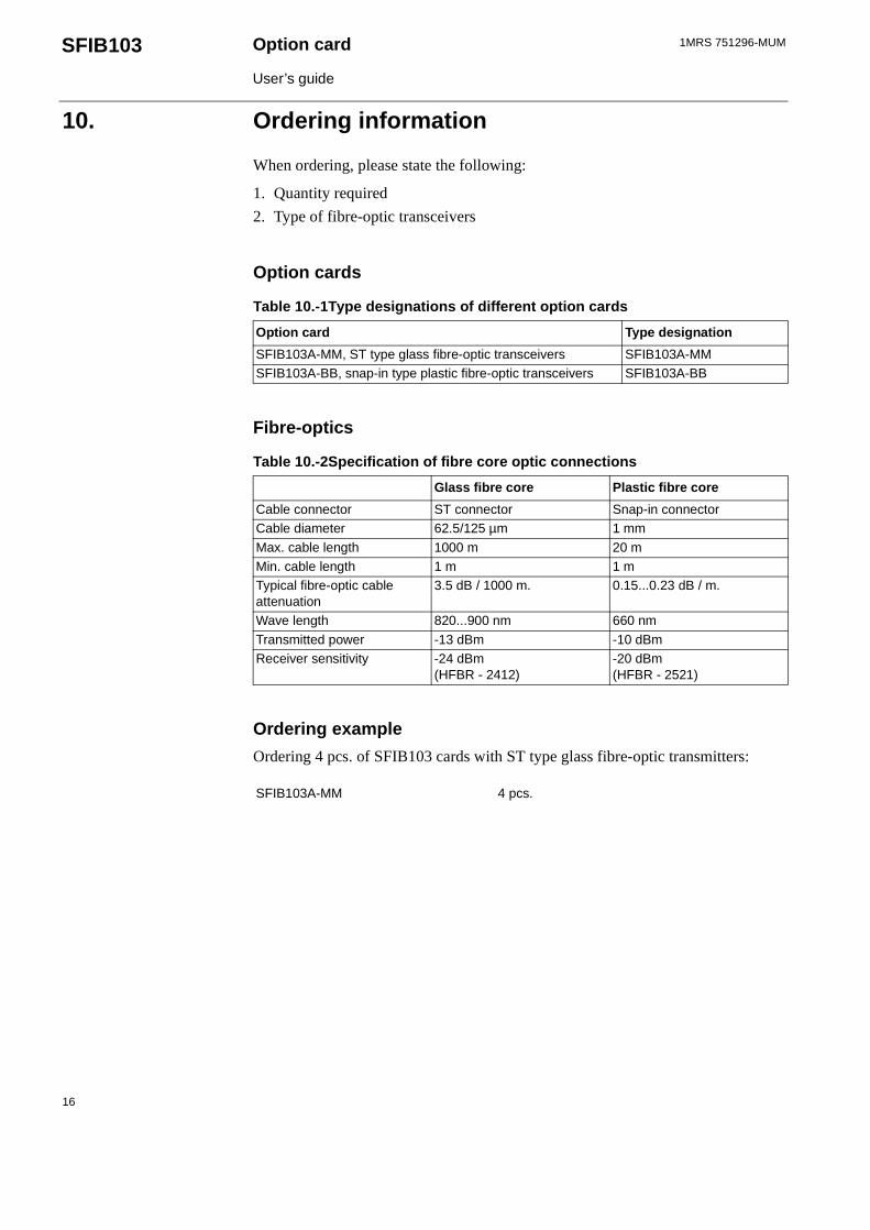
Table 10.-1Type designations of different option cards
Option card Type designation
SFIB103A-MM, ST type glass fibre-optic transceivers SFIB103A-MMSFIB103A-BB, snap-in type plastic fibre-optic transceivers SFIB103A-BB
Table 10.-2Specification of fibre core optic connections
Glass fibre core Plastic fibre core
Cable connector ST connector Snap-in connectorCable diameter 62.5/125 µm 1 mm
Max. cable length 1000 m 20 mMin. cable length 1 m 1 mTypical fibre-optic cable attenuation
3.5 dB / 1000 m. 0.15...0.23 dB / m.
Wave length 820...900 nm 660 nm
Transmitted power -13 dBm -10 dBmReceiver sensitivity -24 dBm
(HFBR - 2412)-20 dBm (HFBR - 2521)
SFIB103A-MM 4 pcs.
1MRS 751296-MUM Option card
User’s guide
SFIB103
17
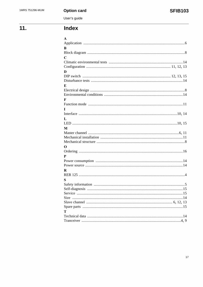
11. Index
�Application ............................................................................................................6�Block diagram ........................................................................................................8�Climatic environmental tests ...............................................................................14Configuration .......................................................................................... 11, 12, 13�DIP switch .............................................................................................. 12, 13, 15Disturbance tests ..................................................................................................14�Electrical design .....................................................................................................8Environmental conditions ....................................................................................14�Function mode .....................................................................................................11�Interface .........................................................................................................10, 14�LED ................................................................................................................10, 15Master channel .................................................................................................6, 11Mechanical installation ........................................................................................11Mechanical structure ..............................................................................................8Ordering ...............................................................................................................16�Power consumption .............................................................................................14Power source ........................................................................................................14�RER 125 .................................................................................................................4 Safety information .................................................................................................5Self-diagnosis ......................................................................................................15Service .................................................................................................................15Size ......................................................................................................................14Slave channel ............................................................................................ 6, 12, 13Spare parts ...........................................................................................................15�Technical data ......................................................................................................14Tranceiver ..........................................................................................................4, 9
18
1MRS 751296-MUMOption card
User’s guide
SFIB103
12. Customer feedback
Date: _____________________To fax: +358 10 224 1094
Category: _ Comment _ Query _ Complaint
In case of feedback related to a specific product, please state the name of the product.
Product: _____________________________________________
Description: _____________________________________________
_____________________________________________
_____________________________________________
_____________________________________________
_____________________________________________
_____________________________________________
_____________________________________________
_____________________________________________
_____________________________________________
Initiator: _____________________________________________
Issuer: _____________________________________________
Company: _____________________________________________
Country: _____________________________________________
Telefax no/
e-mail address: _____________________________________________
If necessary, additional pages may be enclosed.


ABB Substation Automation OyP.O. Box 699FIN-65101 VAASAFinlandTel. +358 10 224 000Fax. +358 10 224 1094www.abb.com/substationautomation
1MR
S 7
5129
6-M
UM
EN
11.
2000