Embed Size (px)
Citation preview
User's Guide 11/2002 Edition
Measuring CyclesSINUMERIK 840D/840Di/810D

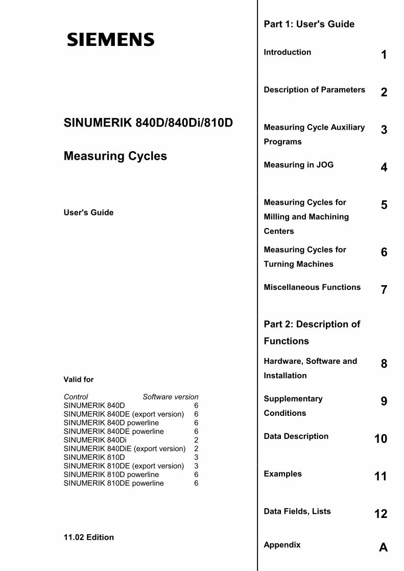
SINUMERIK 840D/840Di/810D
Measuring Cycles
11.02 Edition
User's Guide
Part 1: User's Guide
Introduction 1
Description of Parameters 2
Measuring Cycle AuxiliaryPrograms
3
Measuring in JOG 4
Measuring Cycles forMilling and MachiningCenters
5
Measuring Cycles forTurning Machines
6
Miscellaneous Functions 7
Part 2: Description ofFunctions
Hardware, Software andInstallation
8
SupplementaryConditions
9
Data Description 10
Examples 11
Data Fields, Lists 12
Appendix A
Valid for
Control Software versionSINUMERIK 840D 6SINUMERIK 840DE (export version) 6SINUMERIK 840D powerline 6SINUMERIK 840DE powerline 6SINUMERIK 840Di 2SINUMERIK 840DiE (export version) 2SINUMERIK 810D 3SINUMERIK 810DE (export version) 3SINUMERIK 810D powerline 6SINUMERIK 810DE powerline 6
0 Contents 11.02 0
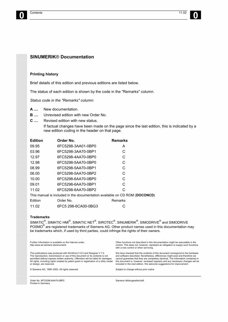
SINUMERIK® Documentation
Printing history
Brief details of this edition and previous editions are listed below.
The status of each edition is shown by the code in the "Remarks" column.
Status code in the "Remarks" column:
A .... New documentation.B .... Unrevised edition with new Order No.C .... Revised edition with new status.
If factual changes have been made on the page since the last edition, this is indicated by anew edition coding in the header on that page.
Edition Order No. Remarks09.9503.96
6FC5298-3AA01-0BP06FC5298-3AA70-0BP1
AC
12.97 6FC5298-4AA70-0BP0 C12.98 6FC5298-5AA70-0BP0 C08.99 6FC5298-5AA70-0BP1 C06.00 6FC5298-5AA70-0BP2 C10.00 6FC5298-6AA70-0BP0 C09.01 6FC5298-6AA70-0BP1 C11.02 6FC5298-6AA70-0BP2 CThis manual is included in the documentation available on CD ROM (DOCONCD)Edition Order No. Remarks11.02 6FC5 298-6CA00-0BG3 C
TrademarksSIMATIC®, SIMATIC HMI®, SIMATIC NET®, SIROTEC®, SINUMERIK®, SIMODRIVE® and SIMODRIVEPOSMO® are registered trademarks of Siemens AG. Other product names used in this documentation maybe trademarks which, if used by third parties, could infringe the rights of their owners.
Further information is available on the Internet under:http:/www.ad.siemens.de/sinumerik
This publications was produced with WinWord V 8.0 and Designer V 7.0.The reproduction, transmission or use of this document or its contents is notpermitted without express written authority. Offenders will be liable for damages.All rights, including rights created by patent grant or registration of a utility modelor design, are reserved.
© Siemens AG, 1995–2002. All rights reserved
Other functions not described in this documentation might be executable in thecontrol. This does not, however, represent an obligation to supply such functionswith a new control or when servicing.
We have checked that the contents of this document correspond to the hardwareand software described. Nonetheless, differences might exist and therefore wecannot guarantee that they are completely identical. The information contained inthis document is, however, reviewed regularly and any necessary changes will beincluded in the next edition. We welcome suggestions for improvement.
Subject to change without prior notice
Order No. 6FC5298-6AA70-0BP2Printed in Germany
Siemens Aktiengesellschaft
Siemens AG, 2002. All rights reservedSINUMERIK 840D/840Di/810D User's Guide Measuring Cycles (BNM) – 11.02 Edition 0-5
0 11.02 Contents 0
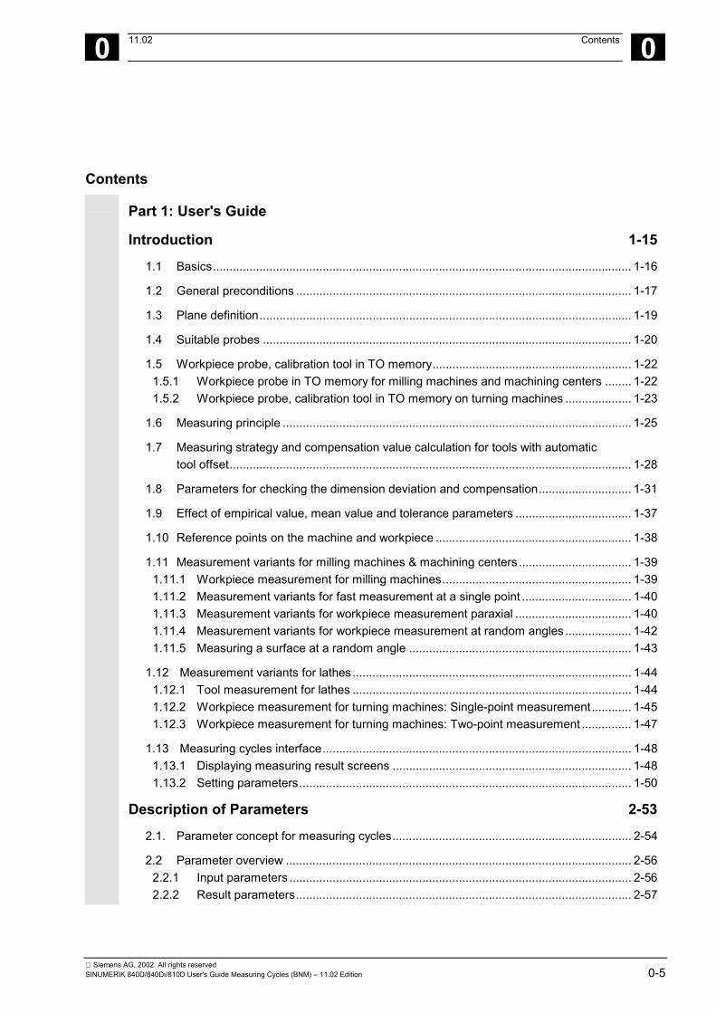
Contents
Part 1: User's Guide
Introduction 1-15
1.1 Basics.............................................................................................................................. 1-16
1.2 General preconditions ..................................................................................................... 1-17
1.3 Plane definition................................................................................................................ 1-19
1.4 Suitable probes ............................................................................................................... 1-20
1.5 Workpiece probe, calibration tool in TO memory............................................................ 1-221.5.1 Workpiece probe in TO memory for milling machines and machining centers ........ 1-221.5.2 Workpiece probe, calibration tool in TO memory on turning machines .................... 1-23
1.6 Measuring principle ......................................................................................................... 1-25
1.7 Measuring strategy and compensation value calculation for tools with automatictool offset......................................................................................................................... 1-28
1.8 Parameters for checking the dimension deviation and compensation............................ 1-31
1.9 Effect of empirical value, mean value and tolerance parameters ................................... 1-37
1.10 Reference points on the machine and workpiece ........................................................... 1-38
1.11 Measurement variants for milling machines & machining centers .................................. 1-391.11.1 Workpiece measurement for milling machines......................................................... 1-391.11.2 Measurement variants for fast measurement at a single point ................................. 1-401.11.3 Measurement variants for workpiece measurement paraxial ................................... 1-401.11.4 Measurement variants for workpiece measurement at random angles .................... 1-421.11.5 Measuring a surface at a random angle ................................................................... 1-43
1.12 Measurement variants for lathes.................................................................................... 1-441.12.1 Tool measurement for lathes .................................................................................... 1-441.12.2 Workpiece measurement for turning machines: Single-point measurement............ 1-451.12.3 Workpiece measurement for turning machines: Two-point measurement ............... 1-47
1.13 Measuring cycles interface............................................................................................. 1-481.13.1 Displaying measuring result screens ........................................................................ 1-481.13.2 Setting parameters.................................................................................................... 1-50
Description of Parameters 2-53
2.1. Parameter concept for measuring cycles........................................................................ 2-54
2.2 Parameter overview ........................................................................................................ 2-562.2.1 Input parameters ....................................................................................................... 2-562.2.2 Result parameters..................................................................................................... 2-57
Siemens AG, 2002. All rights reserved0-6 SINUMERIK 840D/840Di/810D User's Guide Measuring Cycles (BNM) – 11.02 Edition
0 Contents 11.02 0
2.3 Description of the most important defining parameters...................................................2-582.3.1 Measurement variant: _MVAR ..................................................................................2-582.3.2 Number of measuring axis: _MA...............................................................................2-612.3.3 Tool number and tool name: _TNUM and _TNAME .................................................2-622.3.4 Offset number _KNUM..............................................................................................2-632.3.5 Offset number _KNUM with flat D number structure.................................................2-652.3.6 Variable measuring speed: _VMS.............................................................................2-662.3.7 Compensation angle position for monodirectional probe: _CORA............................2-662.3.8 Tolerance parameters: _TZL, _TMV, _TUL, _TLL, _TDIF and _TSA.......................2-672.3.9 Multiplication factor for measurement path 2a: _FA..................................................2-682.3.10 Probe type/Probe number: _PRNUM ........................................................................2-692.3.11 Empirical value/mean value: _EVNUM .....................................................................2-702.3.12 Multiple measurement at the same location: _NMSP ...............................................2-712.3.13 Weighting factor k for averaging: _K .........................................................................2-71
2.4. Description of output parameters ...................................................................................2-722.4.1 Measuring cycle results in _OVR ..............................................................................2-722.4.2 Measuring cycle results in _OVI ................................................................................2-73
Measuring Cycle Auxiliary Programs 3-75
3.1 Package structure of measuring cycles..........................................................................3-76
3.2 Measuring cycle subroutines ..........................................................................................3-773.2.1 CYCLE103: Parameter definition for measuring cycles ............................................3-783.2.2 CYCLE116: Calculation of center point and radius of a circle...................................3-79
3.3 Measuring cycle user programs .....................................................................................3-813.3.1 CYCLE198: User program prior to calling measuring cycle ......................................3-813.3.2 CYCLE199: User program at the end of a measuring cycle .....................................3-82
3.4 Subpackages..................................................................................................................3-83
Measuring in JOG 4-85
4.1 General preconditions ....................................................................................................4-86
4.2 Workpiece measurement ...............................................................................................4-894.2.1 Operation and function sequence of workpiece measurement .................................4-904.2.2 Measuring an edge....................................................................................................4-914.2.3 Measuring a corner ...................................................................................................4-924.2.4 Measuring a hole .......................................................................................................4-944.2.5 Measuring a spigot ....................................................................................................4-954.2.6 Calibrating the measuring probe ...............................................................................4-96
4.3 Tool measurement .........................................................................................................4-994.3.1 Operation and function sequence of tool measurement ...........................................4-994.3.2 Tool measurement ..................................................................................................4-1004.3.3 Calibrating the tool measuring probe ......................................................................4-101
Siemens AG, 2002. All rights reservedSINUMERIK 840D/840Di/810D User's Guide Measuring Cycles (BNM) – 11.02 Edition 0-7
0 11.02 Contents 0
Measuring Cycles for Milling and Machining Centers 5-103
5.1 General preconditions ................................................................................................... 5-104
5.2 CYCLE971 Tool measuring for milling tools ................................................................. 5-1065.2.1 CYCLE971 Measuring strategy............................................................................... 5-1085.2.2 CYCLE971 Calibrate tool probe.............................................................................. 5-1105.2.3 CYCLE971 Measure tool......................................................................................... 5-114
5.3 CYCLE976 Calibrate workpiece probe.......................................................................... 5-1195.3.1 CYCLE976 Calibrate workpiece probe in any hole (plane) with known
hole center .............................................................................................................. 5-1225.3.2 CYCLE976 Calibrate workpiece probe in any hole (plane) with unknown hole
center (measuring cycles SW 4.4 and higher) ........................................................ 5-1245.3.3 CYCLE976 Calibrate workpiece probe on a random surface ................................. 5-1265.3.4 Calibrate workpiece probe in applicate with calculation of probe length
(measuring cycles SW 4.4. and higher) .................................................................. 5-128
5.4 CYCLE977 Workpiece measurement: Hole/shaft/groove/web/rectangle (paraxial) ..... 5-1305.4.1 CYCLE977 Measure hole, shaft, groove, web, rectangle ....................................... 5-1345.4.2 CYCLE977 ZO calculation in hole, shaft, groove, web, rectangle .......................... 5-140
5.5 CYCLE978 Workpiece measurement: Surface ............................................................ 5-1465.5.1 CYCLE978 ZO calculation on a surface (single point measuring cycle)................. 5-1495.5.2 CYCLE978 Single-point measurement ................................................................... 5-152
5.6 CYCLE979 Workpiece measurement: Hole/shaft/groove/web (at a random angle)..... 5-1565.6.1 CYCLE979 Measure hole, shaft, groove, web ........................................................ 5-1595.6.2 CYCLE979 ZO calculation in hole, shaft, groove, web ........................................... 5-164
5.7 CYCLE998 Angular measurement (ZO calculation) ..................................................... 5-169
5.8 CYCLE961 Automatic setup of inside and outside corner ............................................ 5-1805.8.1 Automatic setup of corner with distances and angles specified.............................. 5-1805.8.2 Automatic setup of corner by defining 4 points (measuring cycles ≥ SW 4.5)........ 5-185
Measuring Cycles for Turning Machines 6-189
6.1 General preconditions .................................................................................................. 6-190
6.2 CYCLE972 Tool measurement .................................................................................... 6-1926.2.1 CYCLE972 Calibrating the tool probe ..................................................................... 6-1946.2.2 CYCLE972 Determine dimensions of calibration tools ........................................... 6-1976.2.3 CYCLE972 Measure tool......................................................................................... 6-198
6.3 CYCLE982 Tool measurement (SW 5.3 and higher)................................................... 6-2036.3.1 CYCLE982 Calibrate tool measuring probe ............................................................ 6-2086.3.2 CYCLE982 Measure tool......................................................................................... 6-2106.3.3 CYCLE982 Automatic tool measurement ............................................................... 6-2216.3.4 Incremental calibration (SW 6.2 and higher)........................................................... 6-228
Siemens AG, 2002. All rights reserved0-8 SINUMERIK 840D/840Di/810D User's Guide Measuring Cycles (BNM) – 11.02 Edition
0 Contents 11.02 0
6.3.5 Incremental measurement (SW 6.2 and higher) .....................................................6-2316.3.6 Milling tool: suppression of starting angle positioning with _STA1 (≥ SW 6.2)........6-237
6.4 CYCLE973 Calibrate workpiece probe.........................................................................6-2386.4.1 CYCLE973 Calibrate in the reference groove (plane) .............................................6-2406.4.2 CYCLE973 Calibrate on a random surface .............................................................6-242
6.5 CYCLE974 Workpiece measurement ..........................................................................6-2446.5.1 CYCLE974 Single-point measurement ZO calculation ...........................................6-2466.5.2 CYCLE974 Single-point measurement ...................................................................6-2496.5.3 CYCLE974 Single-point measurement with reversal ..............................................6-253
6.6 CYCLE994 Two-point measurement............................................................................6-257
6.7 Complex example for workpiece measurement ...........................................................6-262
Miscellaneous Functions 7-265
7.1 Logging of measuring results .......................................................................................7-2667.1.1 Storing the log .........................................................................................................7-2667.1.2 Handling of log cycles..............................................................................................7-2677.1.3 Selecting the log contents .......................................................................................7-2697.1.4 Log format ...............................................................................................................7-2717.1.5 Log header ..............................................................................................................7-2727.1.6 Variable for logging..................................................................................................7-2737.1.7 Example of measuring result log.............................................................................7-274
7.2 Cycle support for measuring cycles..............................................................................7-2767.2.1 Files for cycle support..............................................................................................7-2777.2.2 Loading the cycle support........................................................................................7-2777.2.3 Assignment of calls and measuring cycles..............................................................7-2787.2.4 Description of parameterization cycles....................................................................7-279
7.3 Measuring cycle support in the program editor (≥ SW 6.2) ..........................................7-2907.3.1 Menus, cycle explanation ........................................................................................7-2907.3.2 New functions of the input forms.............................................................................7-2917.3.3 GUD variables for adaptation of measuring cycle support ......................................7-297
Part 2: Description of Functions
Hardware, Software and Installation 8-3018.1 Overview.......................................................................................................................8-302
8.2 Hardware requirements ................................................................................................8-3038.2.1 General hardware requirements..............................................................................8-3038.2.2 Probe connection.....................................................................................................8-3038.2.3 Measuring in JOG ...................................................................................................8-303
8.3 Software requirements .................................................................................................8-3088.3.1 General measuring cycles.......................................................................................8-308
Siemens AG, 2002. All rights reservedSINUMERIK 840D/840Di/810D User's Guide Measuring Cycles (BNM) – 11.02 Edition 0-9
0 11.02 Contents 0
8.3.2 Measuring in JOG ................................................................................................... 8-309
8.4 Function check ............................................................................................................. 8-310
8.5 Start-up sequences ...................................................................................................... 8-3128.5.1 Start-up flowchart for measuring cycles and probe circuit ...................................... 8-3128.5.2 Starting up the measuring cycle interface for the MMC 102 ................................... 8-315
Supplementary Conditions 9-317
Data Description 10-319
10.1 Machine data for machine cycle runs......................................................................... 10-320
10.2 Cycle data................................................................................................................... 10-32310.2.1 Data concept for measuring cycles ....................................................................... 10-32310.2.2 Data blocks for measuring cycles: GUD5.DEF and GUD6.DEF........................... 10-32410.2.3 Central values ....................................................................................................... 10-32810.2.4 Central bits ............................................................................................................ 10-33310.2.5 Central strings ....................................................................................................... 10-33610.2.6 Channel-oriented values ....................................................................................... 10-33710.2.7 Channel-oriented bits ............................................................................................ 10-339
10.3 Data for measuring in JOG ........................................................................................ 10-34410.3.1 Machine data for ensuring ability to function......................................................... 10-34410.3.2 Modifying the GUD7 data block ............................................................................ 10-34610.3.3 Settings in data block GUD6................................................................................. 10-34910.3.4 Loading files for measuring in JOG....................................................................... 10-351
Examples 11-353
11.1 Determining the repeat accuracy ............................................................................... 11-354
11.2 Adapting the data for a particular machine ................................................................ 11-355
Data Fields, Lists 12-359
12.1 Machine data.............................................................................................................. 12-360
12.2 Measuring cycle data ................................................................................................. 12-360
12.3 Alarms ........................................................................................................................ 12-361
Appendix A-369A Overview of measuring cycle parameters ....................................................................A-371B Abbreviations................................................................................................................A-405C Terms ...........................................................................................................................A-407D References...................................................................................................................A-415E Index.............................................................................................................................A-429F Identifiers......................................................................................................................A-434
Siemens AG, 2002. All rights reserved0-10 SINUMERIK 840D/840Di/810D User's Guide Measuring Cycles (BNM) – 11.02 Edition
0 Preface 11.02Structure of the manual 0
840 DNCU 571
840 DNCU 572NCU 573
810 D 840 Di
PrefaceOrganization of documentationThe SINUMERIK documentation is organized on 3 different levels:• General Documentation• User Documentation• Manufacturer/Service Documentation
Target groupThis manual is aimed at machine tool users. It provides detailed information foroperating the SINUMERIK 840D, 810D.
Standard scopeThis Operator's Guide describes only the functionality of the standard scope.A description of add-on features or modifications made by the machine builder arenot included in this guide.For more detailed information on SINUMERIK 840D, 810D publications and otherpublications covering all SINUMERIK controls (e.g. universal interface, measuringcycles...), please contact your local Siemens office.Other functions not described in this documentation might be executable in thecontrol. This does not, however, represent an obligation to supply such functionswith a new control or when servicing.
ValidityThis User's Guide is valid for the following controls:SINUMERIK 810D, 840D, 840Di, MMC 100 and MMC 102/103.Software versions stated in the User's Guide refer to the 840D and their 810Dequivalent, e.g. SW 6 (840D) corresponds to SW 3 (810D).
SINUMERIK 840D powerlineFrom 09.2001• SINUMERIK 840D powerline and• SINUMERIK 840DE powerlineare available, with improved performance. A list of the availablepowerline modules can be found in the hardware description/PHD/ in Section 1.1
SINUMERIK 810D powerlineFrom 12.2001• SINUMERIK 810D powerline and• SINUMERIK 810DE powerlineare available, with improved performance. A list of the availablepowerline modules can be found in the hardware description/PHC/ in Section 1.1
Siemens AG, 2002. All rights reservedSINUMERIK 840D/840Di/810D User's Guide Measuring Cycles (BNM) – 11.02 Edition 0-11
0 11.02 PrefaceStructure of the manual 0
840 DNCU 571
840 DNCU 572NCU 573
810 D 840 Di
Hotline Please address any questions to the following hotline:A&D Technical Support Phone: ++49-(0)180-5050-222
Fax: ++49-(0)180-5050-223Email: [email protected]
If you have any questions (suggestions, corrections) concerningthe documentation, please fax or e-mail them to the followingaddress:
Fax: ++49-(0)0131-98-2176Email: [email protected]
Fax form: See answer form at the end of the document.
Internet address http://www.ad.siemens.de/sinumerik
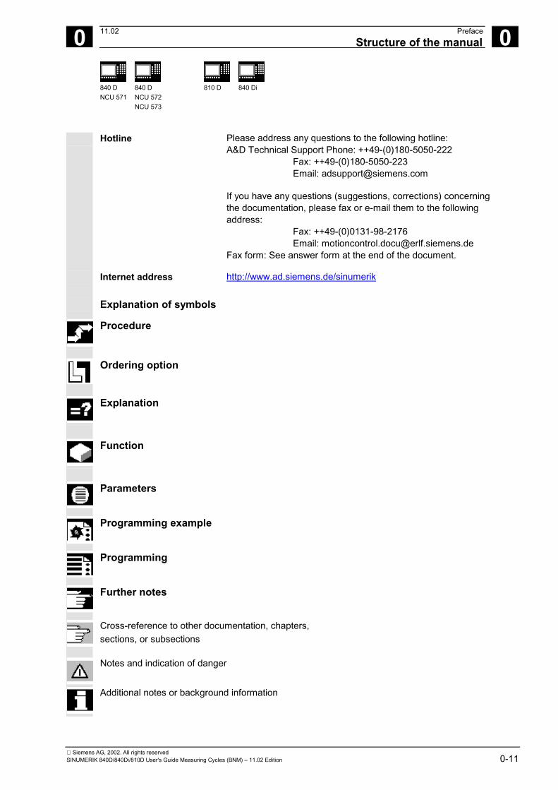
Explanation of symbols
Procedure
Ordering option
Explanation
Function
Parameters
Programming example
Programming
Further notes
Cross-reference to other documentation, chapters,sections, or subsections
Notes and indication of danger
Additional notes or background information
Siemens AG, 2002. All rights reserved0-12 SINUMERIK 840D/840Di/810D User's Guide Measuring Cycles (BNM) – 11.02 Edition
0 Preface 11.02Use as intended 0
840 DNCU 571
840 DNCU 572NCU 573
810 D 840 Di
Warnings
The following warnings are used with graded severity.
Danger
Indicates an imminently hazardous situation which, ifnot avoided, will result in death or serious injury or insubstantial property damage.
Warning
Indicates a potentially hazardous situation which, if notavoided, could result in death or serious injury or insubstantial property damage.
Caution
Used with the safety alert symbol indicates a potentiallyhazardous situation which, if not avoided, may result inminor or moderate injury or in property damage.
Caution
Used without safety alert symbol indicates a potentiallyhazardous situation which, if not avoided, may result inproperty damage.
Notice
Used without the safety alert symbol indicates apotential situation which, if not avoided, may result in anundesirable result or state.
Siemens AG, 2002. All rights reservedSINUMERIK 840D/840Di/810D User's Guide Measuring Cycles (BNM) – 11.02 Edition 0-13
0 11.02 PrefaceUse as intended 0
840 DNCU 571
840 DNCU 572NCU 573
810 D 840 Di
BasisYour SIEMENS SINUMERIK 840D, 804Di, 810D isstate of the art and is manufactured in accordancewith recognized safety regulations, standards andspecifications.
Add-on equipmentUsing special add-on equipment and expandedconfigurations from SIEMENS, SIEMENS controlscan be adapted to suit your specific application.
PersonnelOnly authorized and reliable personnel with therelevant training must be allowed to handle thecontrol. Nobody without the necessary training mustbe allowed to work on the control, not even for ashort time.
The responsibilities of the personnel employed forsetting, operating and maintenance must be clearlydefined and supervised.
BehaviorBefore the control is started up, it must be ensuredthat the Operator's Guide has been read and under-stood by the personnel responsible. The operatingcompany is also responsible for constantlymonitoring the overall technical state of the control(faults and damage apparent from the outside andchanges in response).
Siemens AG, 2002. All rights reserved0-14 SINUMERIK 840D/840Di/810D User's Guide Measuring Cycles (BNM) – 11.02 Edition
0 Preface 11.02Use as intended 0
840 DNCU 571
840 DNCU 572NCU 573
810 D 840 Di
ServiceRepairs must only be carried out in accordance with theinformation given in the Service and Maintenance Guideby personnel trained and qualified in the relevantfield. The relevant safety regulations must be observed.
NoteThe following is contrary to the intended purpose andexonerates the manufacturer from any liability:
Any use whatsoever beyond or deviating from theapplication stated in the above points.
If the control is not in perfect technical condition, oris operated without awareness for safety or the dangersinvolved or without observing the instructions given inthe instruction manual.
If faults that can reduce safety are not remedied beforethe control is started up.
Any modification, overriding or deactivation ofequipment on the control used for the perfectfunctioning, unrestricted use or active and passivesafety.
This can result in unforeseen dangers for:• the health and life of people,• the control, machine and other property of the
operating company and user.
1 12.97 Introduction 1
Siemens AG, 2002. All rights reservedSINUMERIK 840D/840Di/810D User's Guide Measuring Cycles (BNM) – 11.02 Edition 1-15
Introduction
1.1 Basics.............................................................................................................................. 1-16
1.2 General preconditions ..................................................................................................... 1-17
1.3 Plane definition................................................................................................................ 1-19
1.4 Suitable probes ............................................................................................................... 1-20
1.5 Workpiece probe, calibration tool in TO memory............................................................ 1-221.5.1 Workpiece probe in TO memory for milling machines and machining centers ....... 1-221.5.2 Workpiece probe, calibration tool in TO memory on turning machines ................... 1-23
1.6 Measuring principle ......................................................................................................... 1-25
1.7 Measuring strategy and compensation value calculation for tools with automatictool offset......................................................................................................................... 1-28
1.8 Parameters for checking the dimension deviation and compensation............................ 1-31
1.9 Effect of empirical value, mean value and tolerance parameters ................................... 1-37
1.10 Reference points on the machine and workpiece ........................................................... 1-38
1.11 Measurement variants for milling machines & machining centers .................................. 1-391.11.1 Workpiece measurement for milling machines........................................................ 1-391.11.2 Measurement variants for fast measurement at a single point................................ 1-401.11.3 Measurement variants for workpiece measurement paraxial .................................. 1-401.11.4 Measurement variants for workpiece measurement at random angles................... 1-421.11.5 Measuring a surface at a random angle .................................................................. 1-43
1.12 Measurement variants for lathes..................................................................................... 1-441.12.1 Tool measurement for lathes ................................................................................... 1-441.12.2 Workpiece measurement for turning machines: Single-point measurement........... 1-451.12.3 Workpiece measurement for turning machines: Two-point measurement.............. 1-47
1.13 Measuring cycles interface.............................................................................................. 1-481.13.1 Displaying measuring result screens ....................................................................... 1-481.13.2 Setting parameters................................................................................................... 1-50
09.01
1 Introduction 12.971.1 Basics 1
840 DNCU 571
840 DNCU 572NCU 573
810 D 840Di
Siemens AG, 2002. All rights reserved1-16 SINUMERIK 840D/840Di/810D User's Guide Measuring Cycles (BNM) – 11.02 Edition
1.1 Basics
Measuring cycles are general subroutines designed tosolve specific measurement tasks. They can be suitablyadapted to the problem at hand by means of parametersettings.
With regard to measurement applications, a distinctionmust generally be made between tool measurementand workpiece measurement.
Workpiece measurement
For workpiece measurement, a measuring probe ismoved up to the clamped workpiece in the same way asa tool. The flexibility of the measuring cycles makes itpossible to perform nearly all measurements which mayneed to be taken on a milling machine.An automatic tool offset or an additive ZO can beapplied to the result of the tool measurement.The measurement variants which can be implementedwith the measuring cycles available in this configurationare described on the following pages.
Tool measurement
To perform tool measurement, the changed tool, whichin the case of a lathe is usually located in the turret, ismoved up to the probe which is either permanently fixedor swiveled into the working range. The automaticallyderived tool geometry is entered in the relevant tooloffset data record.
08.99
1 12.97 Introduction1.2 General preconditions 1
840 DNCU 571
840 DNCU 572NCU 573
810 D 840Di
Siemens AG, 2002. All rights reservedSINUMERIK 840D/840Di/810D User's Guide Measuring Cycles (BNM) – 11.02 Edition 1-17
1.2 General preconditions
Certain preconditions need to be fulfilled beforemeasuring cycles can be used.
These conditions are described in greater detail in Part2 Description of Functions (from Chapter 8 onwards).
The following checklist is useful in determining whetherall such preconditions are fulfilled:
Machine
• All machine axes are designed in accordance withDIN 66217
Availability of cycles • The data blocks:
GUD5.DEF andGUD6.DEF
have been loaded into the control ("Definitions"directory in file system) and
• the measuring cycles have been loaded into thestandard cycle directory of the control followed by apower ON operation.
Initial position • The reference points have been approached.• All axes are positioned prior to the cycle call in such
a way that the setpoint position can be approachedwithout a change in direction.
• The start position can be reached without collisionsby means of linear interpolation.
Displaying measuring result screensIt is only possible to display measurement resultscreens with an MMC/PCU.
11.02

1 Introduction 12.971.2 General preconditions 1
840 DNCU 571
840 DNCU 572NCU 573
810 D 840Di
Siemens AG, 2002. All rights reserved1-18 SINUMERIK 840D/840Di/810D User's Guide Measuring Cycles (BNM) – 11.02 Edition
Programming
• The inch/metric units system selected in themachine data for the basic setting is active.
• The milling radius compensation and theprogrammable frame are deselected prior to thecycle call.
• All parameters for the cycle call have been definedbeforehand.
• The cycle is called no later than at the 5th programlevel.
• Neither of the operating modes "Block search" or"Dry run" is active since these are automaticallyskipped by the measuring cycles.
• The specified default setting of the supplied datablocks is required to ensure that all exampleprograms run correctly.
• With measuring cycles SW 4.4 and higher,measurement in a programmed measurementsystem that differs from the basic system is possible,i.e. in a metric basic system with active G70 and inan inch basic system with active G71.
• With measuring cycles SW 4.4 and higher,measurement in a programmed measurementsystem that differs from the basic system is possiblewith technology data switched over. This means in ametric basic system with active G700 and in an inchbasic system with active G710.
Software status ID
In the delivery status of the measuring cycles, thecurrent software status of the control is entered inparameter _SI[1] in the GUD6 block, i. e. 5 for SW 5.This parameter must be changed to match themeasuring cycles to older software releases.Example:When using measuring cycles status 5.x.x on a controlwith SW 4, �_SI[1] = 4Precondition:In order to use the measuring cycles, the softwarestatus of the control must be ≥ 3.
09.01
1 12.97 Introduction1.3 Plane definition 1
840 DNCU 571
840 DNCU 572NCU 573
810 D 840Di
Siemens AG, 2002. All rights reservedSINUMERIK 840D/840Di/810D User's Guide Measuring Cycles (BNM) – 11.02 Edition 1-19
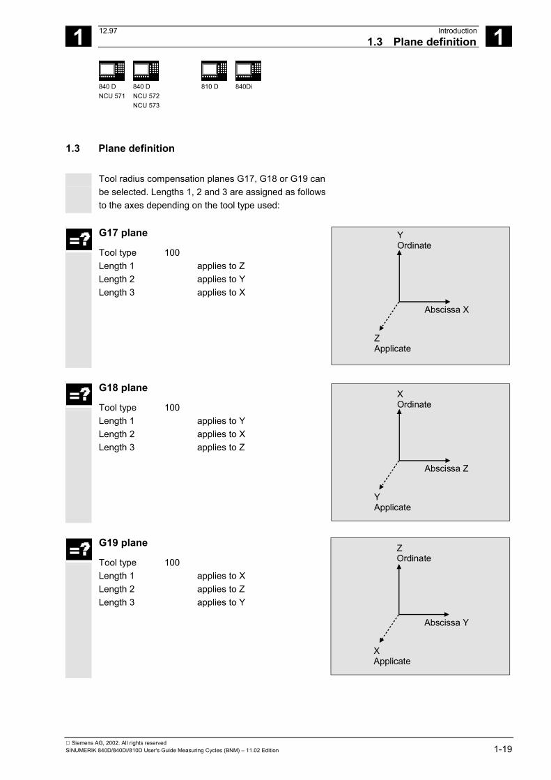
1.3 Plane definition Tool radius compensation planes G17, G18 or G19 can
be selected. Lengths 1, 2 and 3 are assigned as followsto the axes depending on the tool type used:
G17 plane
Tool type 100 Length 1 applies to Z Length 2 applies to Y Length 3 applies to X
YOrdinate
Abscissa X
ZApplicate
G18 plane
Tool type 100 Length 1 applies to Y Length 2 applies to X Length 3 applies to Z
XOrdinate
Abscissa Z
YApplicate
G19 plane
Tool type 100 Length 1 applies to X Length 2 applies to Z Length 3 applies to Y
ZOrdinate
Abscissa Y
XApplicate
1 Introduction 12.971.4 Suitable probes 1
840 DNCU 571
840 DNCU 572NCU 573
810 D 840Di
Siemens AG, 2002. All rights reserved1-20 SINUMERIK 840D/840Di/810D User's Guide Measuring Cycles (BNM) – 11.02 Edition
1.4 Suitable probes
Function
In order to measure tool and workpiece dimensions, atouch-trigger probe is required that supplies a constantsignal (rather than a pulse) when deflected. The probe must be capable of virtually bounce-freeswitching. This is normally achieved by adjusting theprobe mechanically. The probe type is defined in the measuring cycles in aparameter. Various types of probes made by differentmanufacturers are available on the market. Probes areclassified in three groups according to the number ofdirections in which they can be deflected. Classification of probe types
Probe type Turning machines Milling mach. and mach. centers Tool measurement Workpiece measurement Workpiece measurement Multidirectional X X X Bidirectional - X X Monodirectional - - X
While a bidirectional probe can be used for turningmachines, with milling machines and machining centersit is also possible to use a mono probe for workpiecemeasuring. The probe is defined in the measuring cycles in aparameter.
1 12.97 Introduction1.4 Suitable probes 1
840 DNCU 571
840 DNCU 572NCU 573
810 D 840Di
Siemens AG, 2002. All rights reservedSINUMERIK 840D/840Di/810D User's Guide Measuring Cycles (BNM) – 11.02 Edition 1-21
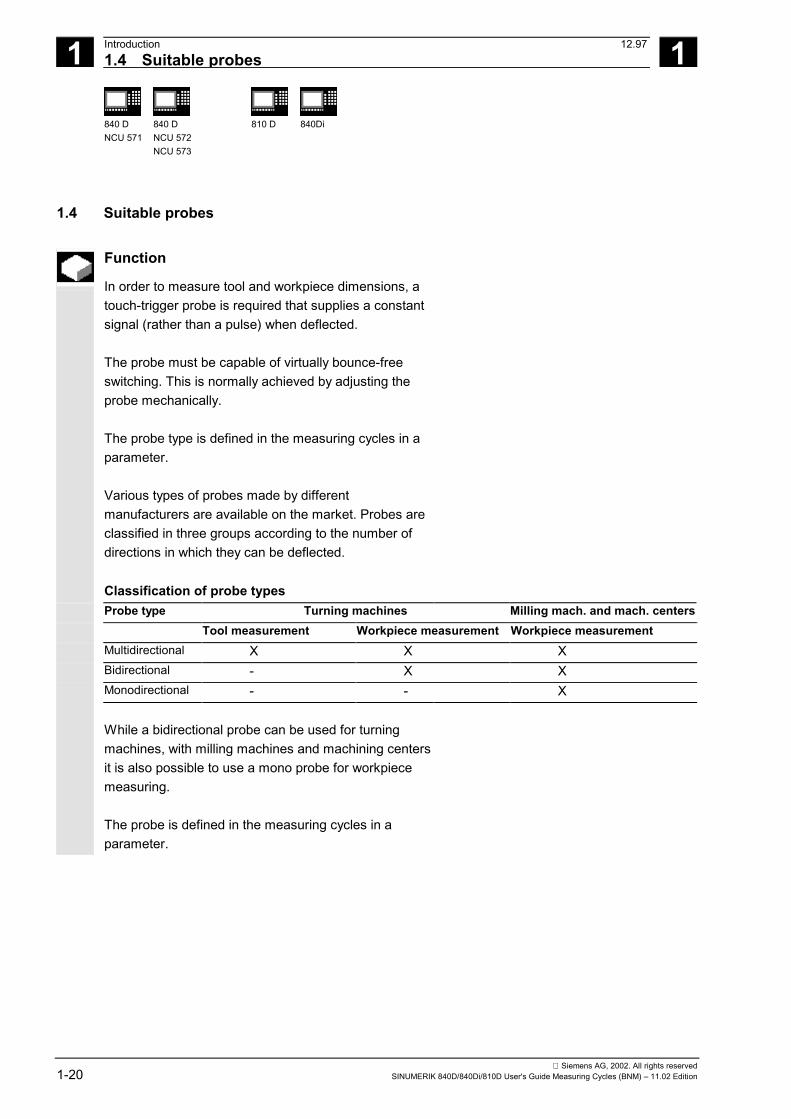
Multidirectional probe (3D)
With this type, measuring cycles for workpiecemeasurement can be used without limitation.
Bidirectional probe
This probe type is used for workpiece measurement onmilling machines and machining centers. This probe type is treated in the same way as amonodirectional probe for workpiece measurement onmilling machines and machining centers.
Monodirectional probe This probe type can only be used for workpiecemeasurement on milling machines and machiningcenters with slight limitations; reference is made to thisin the cycles concerned. In order to be able to use this type of probe on millingmachines and machining centers, it must be possible toposition the spindle with the NC function SPOS and totransmit the switching signal of the probe through 360°to the receiving station (at the machine column).
1 Introduction 12.971.5 Workpiece probe, calibration tool in TO memory 1
840 DNCU 571
840 DNCU 572NCU 573
810 D 840Di
Siemens AG, 2002. All rights reserved1-22 SINUMERIK 840D/840Di/810D User's Guide Measuring Cycles (BNM) – 11.02 Edition
The probe must be mechanically aligned in the spindle insuch a way that measurements can be taken in the fol-lowing directions at the 0 degree position of the spindle.
X-Y plane G17 positive X direction Z-X plane G18 positive Z direction Y-Z plane G19 positive Y direction
The measurement will take longer when using amonodirectional probe since the spindle must bepositioned in the cycle several times by means of SPOS.
1.5 Workpiece probe, calibration tool in TO memory
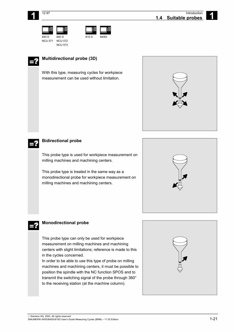
1.5.1 Workpiece probe in TO memory for milling machines and machining centers
Workpiece probe On milling machines and machining centers, the probeis classified as tool type 1x0 and must therefore beentered as such in the TO memory. In SW 4 and higher, tool type 710 (3D probe) can alsobe used. Entry in TO memory
P1 710 Tool typeP3 L1 GeometryP6 r GeometryP21 L1 Tool base dimension
L1
r
_CBIT[14]=1L1
_CBIT[14]=0
1 12.97 Introduction1.5 Workpiece probe, calibration tool in TO memory 1
840 DNCU 571
840 DNCU 572NCU 573
810 D 840Di
Siemens AG, 2002. All rights reservedSINUMERIK 840D/840Di/810D User's Guide Measuring Cycles (BNM) – 11.02 Edition 1-23
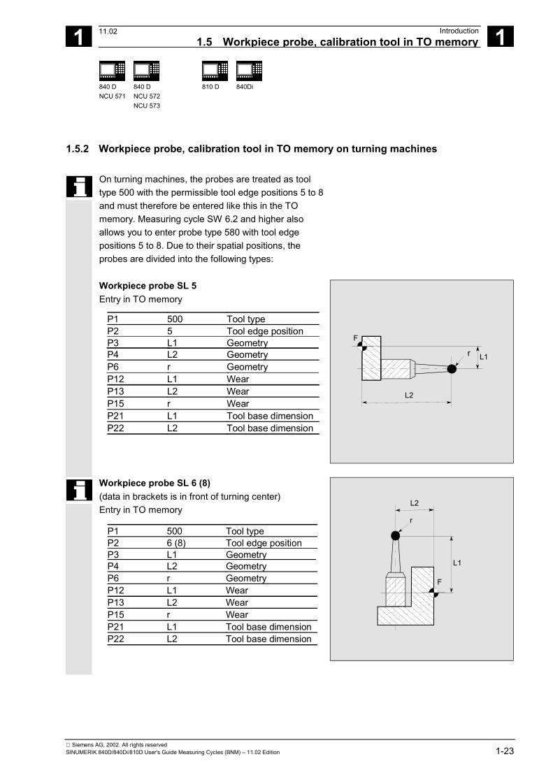
1.5.2 Workpiece probe, calibration tool in TO memory on turning machines
On turning machines, the probes are treated as tooltype 500 with the permissible tool edge positions 5 to 8and must therefore be entered like this in the TOmemory. Measuring cycle SW 6.2 and higher alsoallows you to enter probe type 580 with tool edgepositions 5 to 8. Due to their spatial positions, theprobes are divided into the following types:
Workpiece probe SL 5 Entry in TO memory
P1 500 Tool typeP2 5 Tool edge positionP3 L1 GeometryP4 L2 GeometryP6 r GeometryP12 L1 WearP13 L2 WearP15 r WearP21 L1 Tool base dimensionP22 L2 Tool base dimension
r
L2
L1
F
Workpiece probe SL 6 (8) (data in brackets is in front of turning center) Entry in TO memory
P1 500 Tool typeP2 6 (8) Tool edge positionP3 L1 GeometryP4 L2 GeometryP6 r GeometryP12 L1 WearP13 L2 WearP15 r WearP21 L1 Tool base dimensionP22 L2 Tool base dimension
L1
L2
F
r
11.02
1 Introduction 12.971.5 Workpiece probe, calibration tool in TO memory 1
840 DNCU 571
840 DNCU 572NCU 573
810 D 840Di
Siemens AG, 2002. All rights reserved1-24 SINUMERIK 840D/840Di/810D User's Guide Measuring Cycles (BNM) – 11.02 Edition
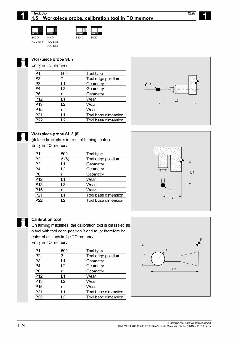
Workpiece probe SL 7 Entry in TO memory
P1 500 Tool typeP2 7 Tool edge positionP3 L1 GeometryP4 L2 GeometryP6 r GeometryP12 L1 WearP13 L2 WearP15 r WearP21 L1 Tool base dimensionP22 L2 Tool base dimension
r
L2
L1
F
Workpiece probe SL 8 (6) (data in brackets is in front of turning center) Entry in TO memory
P1 500 Tool typeP2 8 (6) Tool edge positionP3 L1 GeometryP4 L2 GeometryP6 r GeometryP12 L1 WearP13 L2 WearP15 r WearP21 L1 Tool base dimensionP22 L2 Tool base dimension
L 1
L 2
F
r
Calibration tool On turning machines, the calibration tool is classified asa tool with tool edge position 3 and must therefore beentered as such in the TO memory. Entry in TO memory
P1 500 Tool typeP2 3 Tool edge positionP3 L1 GeometryP4 L2 GeometryP6 r GeometryP12 L1 WearP13 L2 WearP15 r WearP21 L1 Tool base dimensionP22 L2 Tool base dimension
L 1
L 2
F
r
1 12.97 Introduction1.6 Measuring principle 1
840 DNCU 571
840 DNCU 572NCU 573
810 D 840Di
Siemens AG, 2002. All rights reservedSINUMERIK 840D/840Di/810D User's Guide Measuring Cycles (BNM) – 11.02 Edition 1-25
1.6 Measuring principle
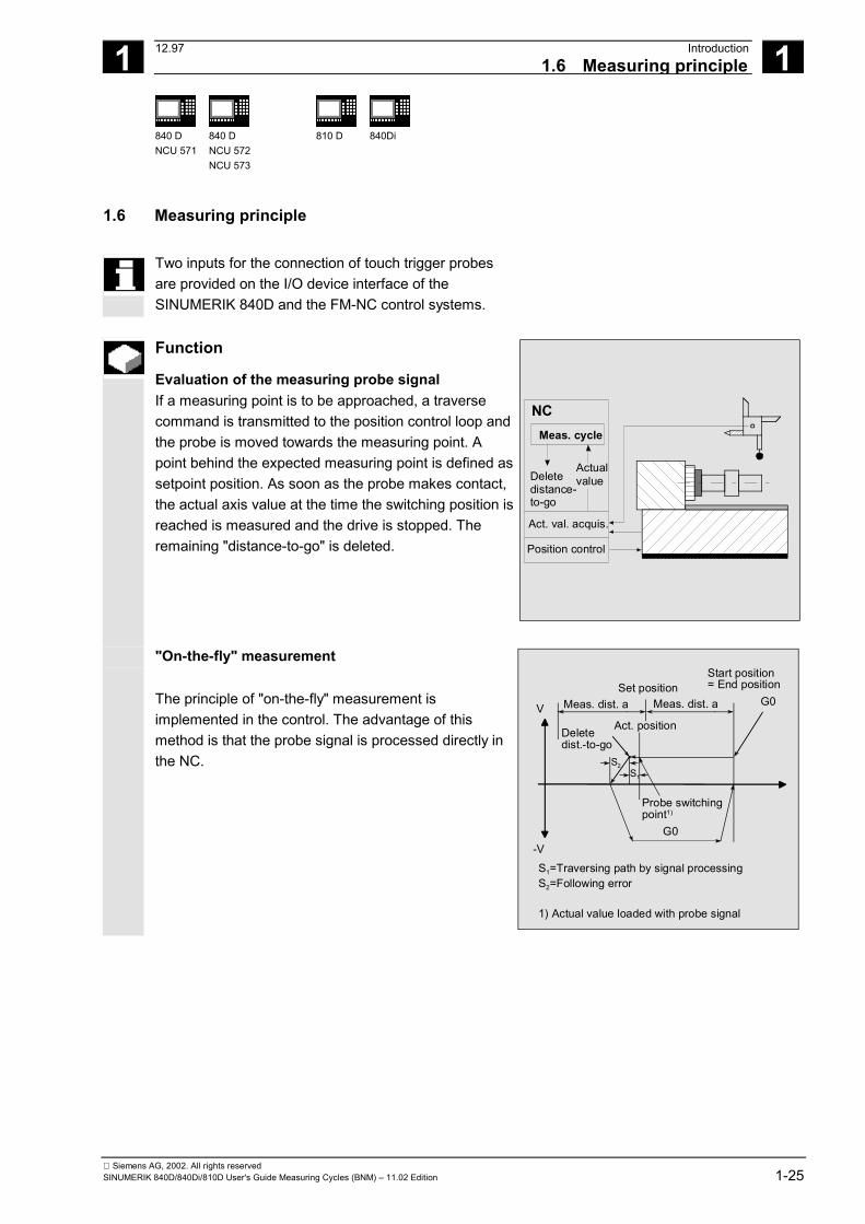
Two inputs for the connection of touch trigger probesare provided on the I/O device interface of theSINUMERIK 840D and the FM-NC control systems.
Function
Evaluation of the measuring probe signal If a measuring point is to be approached, a traversecommand is transmitted to the position control loop andthe probe is moved towards the measuring point. Apoint behind the expected measuring point is defined assetpoint position. As soon as the probe makes contact,the actual axis value at the time the switching position isreached is measured and the drive is stopped. Theremaining "distance-to-go" is deleted.
NCMeas. cycle
Deletedistance-to-go
Actualvalue
Act. val. acquis.
Position control
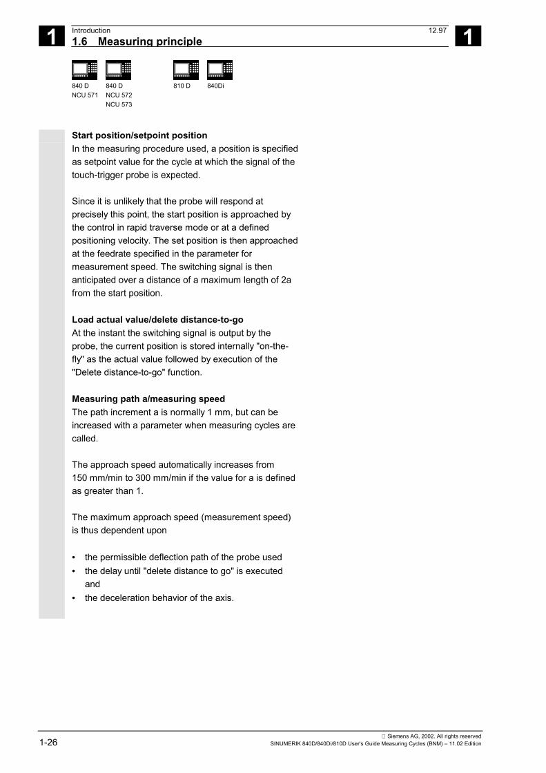
"On-the-fly" measurement
The principle of "on-the-fly" measurement isimplemented in the control. The advantage of thismethod is that the probe signal is processed directly inthe NC.
V
-V
Meas. dist. a Meas. dist. aSet position
Act. positionDeletedist.-to-go
S2S1
G0
G0
Probe switchingpoint1)
Start position= End position
S1=Traversing path by signal processingS2=Following error
1) Actual value loaded with probe signal
1 Introduction 12.971.6 Measuring principle 1
840 DNCU 571
840 DNCU 572NCU 573
810 D 840Di
Siemens AG, 2002. All rights reserved1-26 SINUMERIK 840D/840Di/810D User's Guide Measuring Cycles (BNM) – 11.02 Edition
Start position/setpoint position In the measuring procedure used, a position is specifiedas setpoint value for the cycle at which the signal of thetouch-trigger probe is expected. Since it is unlikely that the probe will respond atprecisely this point, the start position is approached bythe control in rapid traverse mode or at a definedpositioning velocity. The set position is then approachedat the feedrate specified in the parameter formeasurement speed. The switching signal is thenanticipated over a distance of a maximum length of 2afrom the start position. Load actual value/delete distance-to-go At the instant the switching signal is output by theprobe, the current position is stored internally "on-the-fly" as the actual value followed by execution of the"Delete distance-to-go" function. Measuring path a/measuring speed The path increment a is normally 1 mm, but can beincreased with a parameter when measuring cycles arecalled. The approach speed automatically increases from150 mm/min to 300 mm/min if the value for a is definedas greater than 1. The maximum approach speed (measurement speed)is thus dependent upon • the permissible deflection path of the probe used• the delay until "delete distance to go" is executed
and• the deceleration behavior of the axis.
1 12.97 Introduction1.6 Measuring principle 1
840 DNCU 571
840 DNCU 572NCU 573
810 D 840Di
Siemens AG, 2002. All rights reservedSINUMERIK 840D/840Di/810D User's Guide Measuring Cycles (BNM) – 11.02 Edition 1-27
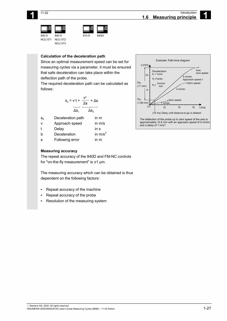
Calculation of the deceleration path Since an optimal measurement speed can be set formeasuring cycles via a parameter, it must be ensuredthat safe deceleration can take place within thedeflection path of the probe. The required deceleration path can be calculated asfollows:
sb = v t + v2
+ ∆s2a
∆s1 ∆s2
·
sb Deceleration path in m v Approach speed in m/s t Delay in s b Deceleration in m/s2
s Following error in m
s [mm]
10
5
Ds2
(11 mm)
Ds1
(1.66 mm)0 10 10 10
1 m/min
4 m/min
6 m/min Approach speed v
Axiszero speed
Zero speed
Zero speed
t [ms]
(16 ms) Delay until distance-to-go is deleted
Example: Path-time diagram
The deflection of the probe up to zero speed of the axis is approximately 12.6 mm with an approach speed of 6 m/minand a delay of 1 m/s2!
Decelerationb = 1m/s2
Kv-Factor
Kv=1m/min
min
Measuring accuracy The repeat accuracy of the 840D and FM-NC controlsfor "on-the-fly measurement" is ±1 µm. The measuring accuracy which can be obtained is thusdependent on the following factors: • Repeat accuracy of the machine• Repeat accuracy of the probe• Resolution of the measuring system
11.02
1 Introduction 12.971.7 Measuring strategy and compensation value calculation for tools 1
840 DNCU 571
840 DNCU 572NCU 573
810 D 840Di
Siemens AG, 2002. All rights reserved1-28 SINUMERIK 840D/840Di/810D User's Guide Measuring Cycles (BNM) – 11.02 Edition
1.7 Measuring strategy and compensation value calculation for tools with automatic tooloffset
The actual workpiece dimensions must be measuredexactly in order to be able to determine andcompensate the actual dimensional deviations on theworkpiece.
Function
When taking measurements on the machine, the actualdimensions are derived from the path measuringsystems of the position-controlled feed axes. For eachdimensional deviation determined from the set andactual workpiece dimensions there are many causeswhich essentially can be classified in 3 categories: • Dimensional deviations with causes that are
n o t subject to a particular trend, e.g. positioningscatter of the feedforward axes or differences inmeasurement between the internal measurement(measuring probe) and the external measuringdevice (micrometer, measuring equipment, etc.).
In this case, it is possible to apply so-calledempirical values, which are stored in separatememories. The set/actual difference determined isautomatically compensated by the empirical value.
• Dimensional deviations with causes that a r e
subject to a particular trend, e.g. tool wear orthermal expansion of the leadscrew.
These deviations are compensated by specifyingfixed threshold values.
• Accidental dimensional deviations, e.g. due to
temperature fluctuations, coolant or slightly soiledmeasuring points.
08.99
1 12.97 Introduction1.7 Measuring strategy and compensation value calculation for tools 1
840 DNCU 571
840 DNCU 572NCU 573
810 D 840Di
Siemens AG, 2002. All rights reservedSINUMERIK 840D/840Di/810D User's Guide Measuring Cycles (BNM) – 11.02 Edition 1-29
Assuming the ideal case, only those dimensionaldeviations which are subject to a trend can be takeninto account for compensation value calculation. Since,however, it is hardly ever known to what extent and inwhich direction accidental dimensional deviationsinfluence the measurement result, a strategy (floatingaverage value generation) is needed which derives acompensation value from the actual/set differencemeasured.
Mean value calculation Mean value calculation in combination with a higher-order measurement weighting has proved a suitablemeans to do this. The formula of the mean value generation chosen is:
Mv Mv Mv Dknew old
old i= − −
Mvnew Mean value new = amount of compensation Mvold Mean value prior to last measurement k Weighting factor for average value calculation Di Actual/set difference measured
(minus empirical value, if any)
The mean value calculation takes account of the trendof the dimensional deviations of a machining series,where weighting factor k from which the mean value isderived is selectable. A new measurement result affected by accidentaldimensional deviations only influences the new tooloffset to some extent, depending on the weightingfactor.
1 Introduction 12.971.7 Measuring strategy and compensation value calculation for tools 1
840 DNCU 571
840 DNCU 572NCU 573
810 D 840Di
Siemens AG, 2002. All rights reserved1-30 SINUMERIK 840D/840Di/810D User's Guide Measuring Cycles (BNM) – 11.02 Edition
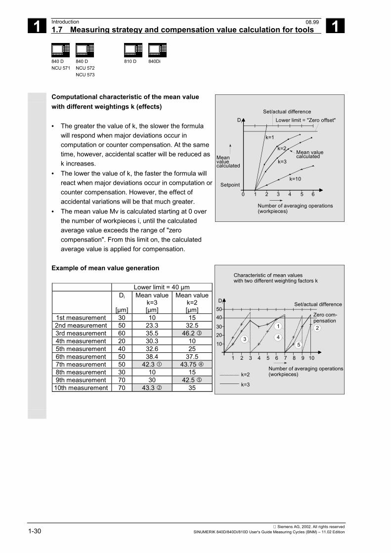
Computational characteristic of the mean valuewith different weightings k (effects) • The greater the value of k, the slower the formula
will respond when major deviations occur incomputation or counter compensation. At the sametime, however, accidental scatter will be reduced ask increases.
• The lower the value of k, the faster the formula willreact when major deviations occur in computation orcounter compensation. However, the effect ofaccidental variations will be that much greater.
• The mean value Mv is calculated starting at 0 overthe number of workpieces i, until the calculatedaverage value exceeds the range of "zerocompensation". From this limit on, the calculatedaverage value is applied for compensation.
Di
Meanvaluecalculated
Setpoint
1 2 3 4 5 60
Number of averaging operations (workpieces)
Set/actual difference
Mean value calculated
k=1
k=2
k=3
k=10
Lower limit = "Zero offset"
Example of mean value generation
Lower limit = 40 µmDi
[µm]
Mean valuek=3[µm]
Mean valuek=2[µm]
1st measurement 30 10 152nd measurement 50 23.3 32.53rd measurement 60 35.5 46.2 �4th measurement 20 30.3 105th measurement 40 32.6 256th measurement 50 38.4 37.57th measurement 50 42.3 � 43.75 �8th measurement 30 10 159th measurement 70 30 42.5 �
10th measurement 70 43.3 � 35
1 2 3 4 5 6 7 8 9 10
Number of averaging operations(workpieces)
Characteristic of mean values with two different weighting factors k
Set/actual difference
30
1020
4050Di
k=2
k=3
Zero com- pensation
1
4
2
53
08.99
1 12.97 Introduction1.8 Parameters for checking the dim. deviation and compensation 1
840 DNCU 571
840 DNCU 572NCU 573
810 D 840Di
Siemens AG, 2002. All rights reservedSINUMERIK 840D/840Di/810D User's Guide Measuring Cycles (BNM) – 11.02 Edition 1-31
1.8 Parameters for checking the dim. deviation and compensation
Explanation
For constant deviations not subject to a trend thedimensional deviation measured can be compensatedby an empirical value for certain measurement variants. For other compensations resulting from dimensionaldeviations, symmetrical tolerance bands are assignedto the set dimension which result in different responses. Empirical value _EVNUM The empirical values are used to suppress dimensionaldeviations that are not subject to a trend. The empirical values are stored in the GUD field_EV empirical value. _EVNUM specifies the number of the empirical valuememory. The actual/set difference determined by themeasuring cycle is corrected by this value before anyfurther correction measures are taken. This is the case• for workpiece measurement with automatic tool
offset• for tool measurement• for single-point measurement with automatic
ZO compensation The tolerance bands (range of permissible dimensionaltolerance) and the responses derived from them havebeen specified as follows:
08.99
1 Introduction 12.971.8 Parameters for checking the dim. deviation and compensation 1
840 DNCU 571
840 DNCU 572NCU 573
810 D 840Di
Siemens AG, 2002. All rights reserved1-32 SINUMERIK 840D/840Di/810D User's Guide Measuring Cycles (BNM) – 11.02 Edition
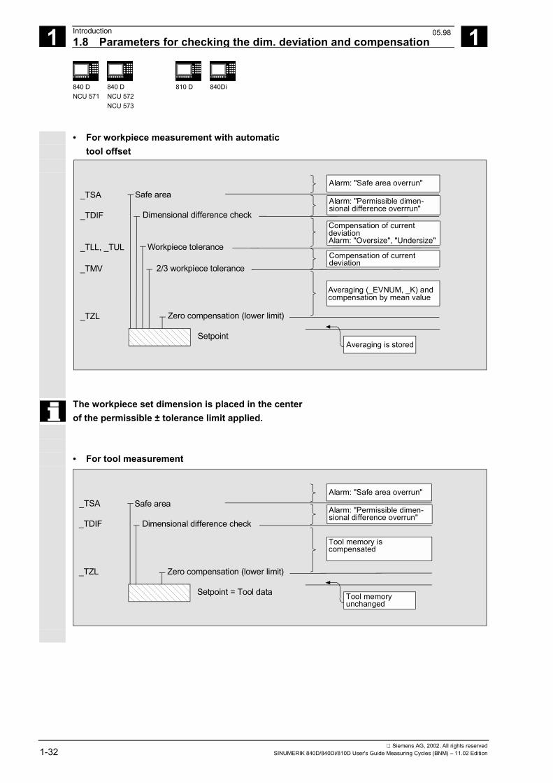
• For workpiece measurement with automatictool offset
Safe area
Dimensional difference check
Workpiece tolerance
2/3 workpiece tolerance
Zero compensation (lower limit)
Setpoint
Alarm: "Safe area overrun"
Alarm: "Permissible dimen-sional difference overrrun"
Compensation of currentdeviationAlarm: "Oversize", "Undersize"
Compensation of currentdeviation
Averaging (_EVNUM, _K) andcompensation by mean value
Averaging is stored
_TSA
_TDIF
_TLL, _TUL
_TMV
_TZL
The workpiece set dimension is placed in the centerof the permissible ± tolerance limit applied.
• For tool measurement
Safe area
Dimensional difference check
Alarm: "Safe area overrun"
Alarm: "Permissible dimen-sional difference overrun"
Tool memory is compensated
_TSA
_TDIF
Zero compensation (lower limit)
Setpoint = Tool data Tool memory unchanged
_TZL
05.98
1 12.97 Introduction1.8 Parameters for checking the dim. deviation and compensation 1
840 DNCU 571
840 DNCU 572NCU 573
810 D 840Di
Siemens AG, 2002. All rights reservedSINUMERIK 840D/840Di/810D User's Guide Measuring Cycles (BNM) – 11.02 Edition 1-33
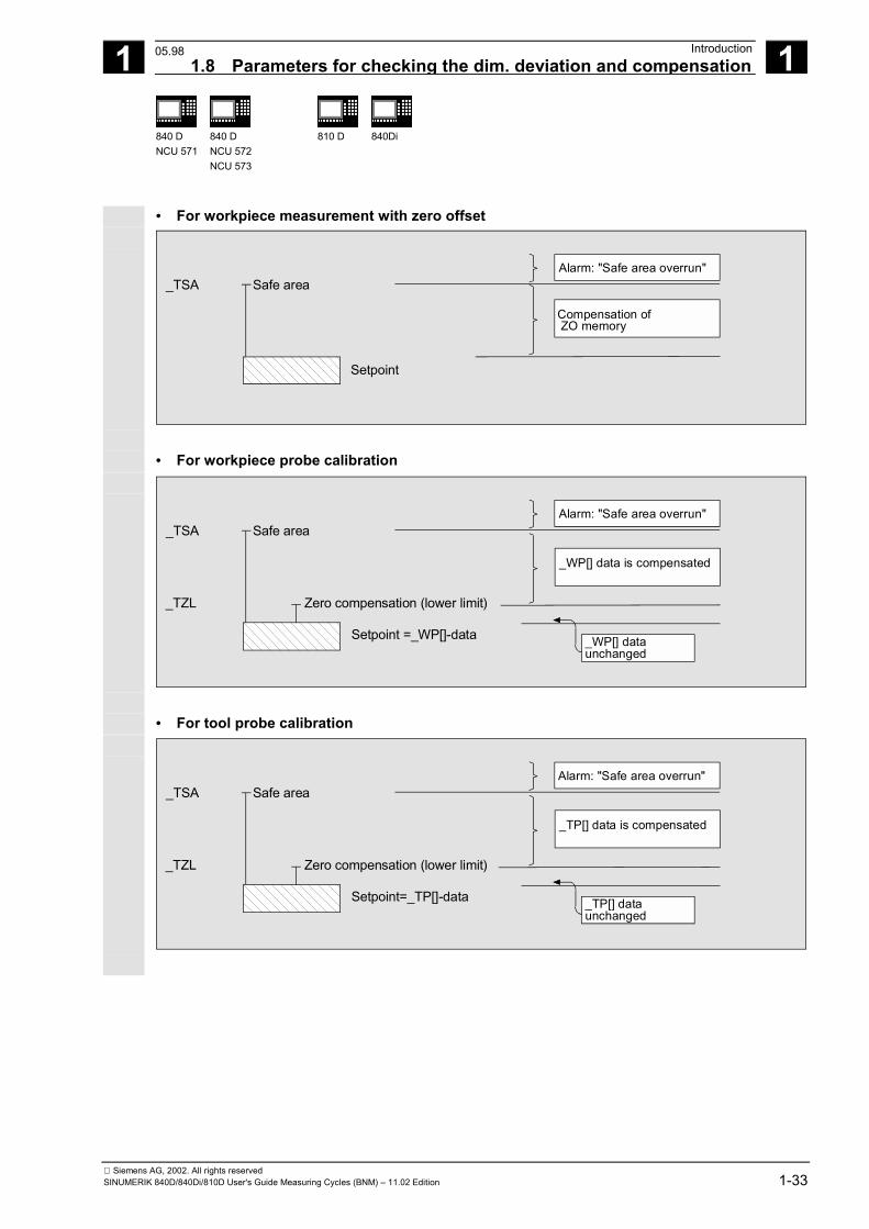
• For workpiece measurement with zero offset
Safe areaAlarm: "Safe area overrun"
Compensation of ZO memory
_TSA
Setpoint
• For workpiece probe calibration
Safe areaAlarm: "Safe area overrun"
_WP[] data is compensated
_TSA
Zero compensation (lower limit)
Setpoint =_WP[]-data _WP[] data unchanged
_TZL
• For tool probe calibration
Safe areaAlarm: "Safe area overrun"
_TP[] data is compensated
_TSA
Zero compensation (lower limit)
Setpoint=_TP[]-data _TP[] data unchanged
_TZL
05.98
1 Introduction 12.971.8 Parameters for checking the dim. deviation and compensation 1
840 DNCU 571
840 DNCU 572NCU 573
810 D 840Di
Siemens AG, 2002. All rights reserved1-34 SINUMERIK 840D/840Di/810D User's Guide Measuring Cycles (BNM) – 11.02 Edition
Safe area _TSA The safe area is active for all measurement variantsand does not affect the offset value; it is used fordiagnosis. If this value is reached,• a defect in the probe,• an incorrect setpoint position or• an illegal deviation from the setpoint positionmay be the cause.
AUTOMATIC operation is interrupted and the programcannot continue. An alarm text appears to warn theuser.
Dimensional difference control _TDIF _TDIF is active only for workpiece measurement withautomatic tool offset and for tool measurement. This limit has no effect on generation of thecompensation value either. When it is reached, the toolis probably worn and needs to be replaced.
An alarm text is displayed to warn the operator and theprogram can be continued by means of an NC start.
This tolerance limit is generally used by the PLC for toolmanagement purposes (twin tools, wear monitoring). Tolerance of the workpiece _TLL, _TUL Both parameters are active only for tool measurementwith automatic tool offset.When measuring a dimensional deviation rangingbetween "2/3 tolerance of workpiece" and "Dimensionaldifference control", this is regarded 100% as toolcompensation. The previous average value is erased. It is therefore possible to effect fast counteraction ifmajor dimensional deviations occur.
08.99
1 12.97 Introduction1.8 Parameters for checking the dim. deviation and compensation 1
840 DNCU 571
840 DNCU 572NCU 573
810 D 840Di
Siemens AG, 2002. All rights reservedSINUMERIK 840D/840Di/810D User's Guide Measuring Cycles (BNM) – 11.02 Edition 1-35
AUTOMATIC operation is interrupted when the tolerancelimit of the workpiece is exceeded. "Oversize" or"undersize" is displayed to the operator depending on thetolerance zone position. Machining can be continued bymeans of NC start.
2/3 workpiece tolerance _TMV _TMV is active only for workpiece measurement withautomatic tool offset. Within the range of "Lower limit" and "2/3 workpiecetolerance" the mean value is calculated according to theformula described in Section "Measuring strategy".
Mvnew is compared with the zero compensation range:
• If Mvnew is greater than this range, compensation is
corrected by Mvnew and the associated mean value
memory is cleared.• If Mvnew is less than this range, no compensation is
carried out to prevent excessively abruptcompensations from being made.
Mean value_EVNUM _EVNUM is active only for workpiece measurement withautomatic tool offset.When calculating the mean value in a series ofmachining operations, the mean value determined by themeasurement at the same measurement location on theprevious workpiece can be taken into account(_CHBIT[4]=1). The mean values are stored in the GUD field _MV meanvalues. _EVNUM also specifies the number of the meanvalue memory in this GUD field.
Weighting factor for mean value calculation _K _K is active only workpiece measurement with automatictool offset. The weighting factor k can be applied to allowdifferent weighting to be given to an individualmeasurement. A new measurement result thus has only a limited effecton the new tool offset as a function of _K.
08.99
1 Introduction 12.971.8 Parameters for checking the dim. deviation and compensation 1
840 DNCU 571
840 DNCU 572NCU 573
810 D 840Di
Siemens AG, 2002. All rights reserved1-36 SINUMERIK 840D/840Di/810D User's Guide Measuring Cycles (BNM) – 11.02 Edition
Bottom limit (zero compensation area) _TZL _TZL active for• Workpiece measurement with automatic tool offset• Tool measurement and calibration for milling tools
and tool probes This tolerance range corresponds to the amount ofmaximum accidental dimensional deviations. It has tobe determined for each machine. No tool compensation is made within these limits. However, the average value of this measuring point isupdated and re-stored with the actual/set differencemeasured for workpiece measurement with automatictool offset, compensated by an empirical value ifnecessary.
1 12.97 Introduction1.9 Effect of empirical value, mean value and tolerance parameters 1
840 DNCU 571
840 DNCU 572NCU 573
810 D 840Di
Siemens AG, 2002. All rights reservedSINUMERIK 840D/840Di/810D User's Guide Measuring Cycles (BNM) – 11.02 Edition 1-37
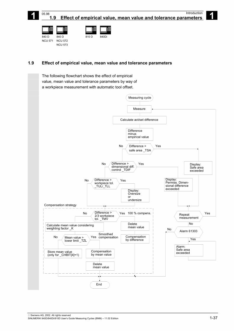
1.9 Effect of empirical value, mean value and tolerance parameters The following flowchart shows the effect of empirical
value, mean value and tolerance parameters by way ofa workpiece measurement with automatic tool offset.
Measuring cycle
Calculate act/set difference
Differenceminusempirical value
Difference >safe area _TSA
Display:Permiss. Dimen-sional difference exceeded
Display:Safe areaexceeded
End
Yes
Repeatmeasurement
Yes
Difference >dimensional diff.control _TDIF
No
No
Difference > workpiece tol._TUL/_TLL
No
Yes
Display:Oversizeor undersize
Yes
Delete mean value
Compensationby difference
Calculate mean value considering weighting factor _K
Difference >2/3 workpiecetol. _TMV
YesNo
Mean value >lower limit _TZL
YesNo
Store mean value(only for _CHBIT[4]=1)
Compensationby mean value
Deletemean value
Smoothedcompensation
Compensation strategy
100 % compens.
Alarm 61303
No
Alarm:Safe areaexceeded
No
Yes
Measure
05.98
1 Introduction 12.971.10 Reference points on the machine and workpiece 1
840 DNCU 571
840 DNCU 572NCU 573
810 D 840Di
Siemens AG, 2002. All rights reserved1-38 SINUMERIK 840D/840Di/810D User's Guide Measuring Cycles (BNM) – 11.02 Edition
1.10 Reference points on the machine and workpiece
Function
The actual axis values of different actual valuesystems must be measured depending on themeasuring process applied. While, for example, themachine actual value can be used to advantage tocalculate the tool length, the workpiece zero isimportant for measuring workpiece dimensions andcalculating the tool wear compensation. Themachine actual value is the dimension between themachine zero and the tool reference point. M = Machine zero M' = Machine zero offset by DRF C = Control zero resulting from PRESET offset W = Workpiece zero F = Tool reference point
XPF
YPF
Y
XM M' C W
Workpiece
F
Spindlechuck
1 12.97 Introduction1.11 Measurement variants for milling machines & machining centers 1
840 DNCU 571
840 DNCU 572NCU 573
810 D 840Di
Siemens AG, 2002. All rights reservedSINUMERIK 840D/840Di/810D User's Guide Measuring Cycles (BNM) – 11.02 Edition 1-39
1.11 Measurement variants for milling machines & machining centers The measurement variants which can be implemented
with measuring cycles for milling machines andmachining centers are illustrated in diagrams below.
1.11.1 Workpiece measurement for milling machines
Tool probe calibration
Result: Probe switching point with reference to machine zero
Calibration tool
Measuring the tool
Result: Tool length Tool radius
Length
Drill
RadiusMill
1 Introduction 12.971.11 Measurement variants for milling machines & machining centers 1
840 DNCU 571
840 DNCU 572NCU 573
810 D 840Di
Siemens AG, 2002. All rights reserved1-40 SINUMERIK 840D/840Di/810D User's Guide Measuring Cycles (BNM) – 11.02 Edition
1.11.2 Measurement variants for fast measurement at a single point
Function
CYCLE978 makes it easy to take a measurement atone point of a surface. The measuring point is approached paraxially. Depending on the measurement variant, the result mayinfluence the selected tool offset or zero offset.
Workpiece measurement, blank measurement
Result: Position, deviation, Zero offset
W
Workpiece measurement, single-pointmeasurement
Result: Actual dimension, deviation, tool offset
1.11.3 Measurement variants for workpiece measurement paraxial
Function
The following measurement variants are provided forthe paraxial measurement of a hole, shaft, groove orweb. They are executed by the cycle CYCLE977.
1 12.97 Introduction1.11 Measurement variants for milling machines & machining centers 1
840 DNCU 571
840 DNCU 572NCU 573
810 D 840Di
Siemens AG, 2002. All rights reservedSINUMERIK 840D/840Di/810D User's Guide Measuring Cycles (BNM) – 11.02 Edition 1-41
Workpiece measurement, measuring the hole
Result: Actual dimension (diameter), deviation, center point, tool offset, zero offset
Workpiece measurement, measuring the shaft
Result: Actual dimension (diameter), deviation, center point, tool offset, zero offset
Workpiece measurement, measuring thegroove
Result: Actual dimension (groove width), deviation, groove center, tool offset, zero offset
Workpiece measurement, measuring the web
Result: Actual dimension (web width), deviation, web center, tool offset, zero offset
Workpiece measurement, measuring theinside rectangle
Result: Actual value rectangle length and width, actual dimension rectangle center, deviation rectangle length and width, deviation rectangle center, tool offset, zero offset
1 Introduction 12.971.11 Measurement variants for milling machines & machining centers 1
840 DNCU 571
840 DNCU 572NCU 573
810 D 840Di
Siemens AG, 2002. All rights reserved1-42 SINUMERIK 840D/840Di/810D User's Guide Measuring Cycles (BNM) – 11.02 Edition
Workpiece measurement, measuring theoutside rectangle
Result: Actual value rectangle length and width, actual dimension rectangle center, deviation rectangle length and width, deviation rectangle center, tool offset, zero offset
1.11.4 Measurement variants for workpiece measurement at random angles
Function
The following measurement variants are provided forthe measurement of a bore, shaft, groove or web atrandom angles. They are executed by CYCLE979.
Triple-point (quadruple-point) measurement atrandom angles
Result: Actual dimension (diameter), deviation, center point, tool offset, zero offset
Hole, shaft, circle segment
1 12.97 Introduction1.11 Measurement variants for milling machines & machining centers 1
840 DNCU 571
840 DNCU 572NCU 573
810 D 840Di
Siemens AG, 2002. All rights reservedSINUMERIK 840D/840Di/810D User's Guide Measuring Cycles (BNM) – 11.02 Edition 1-43
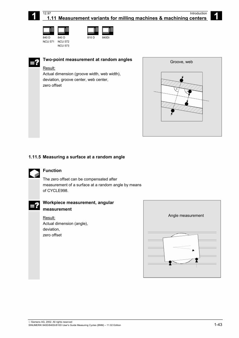
Two-point measurement at random angles
Result: Actual dimension (groove width, web width), deviation, groove center, web center, zero offset
Groove, web
1.11.5 Measuring a surface at a random angle
Function
The zero offset can be compensated aftermeasurement of a surface at a random angle by meansof CYCLE998.
Workpiece measurement, angularmeasurement
Result: Actual dimension (angle), deviation, zero offset
Angle measurement
1 Introduction 12.971.12 Measurement variants for lathes 1
840 DNCU 571
840 DNCU 572NCU 573
810 D 840Di
Siemens AG, 2002. All rights reserved1-44 SINUMERIK 840D/840Di/810D User's Guide Measuring Cycles (BNM) – 11.02 Edition
1.12 Measurement variants for lathes
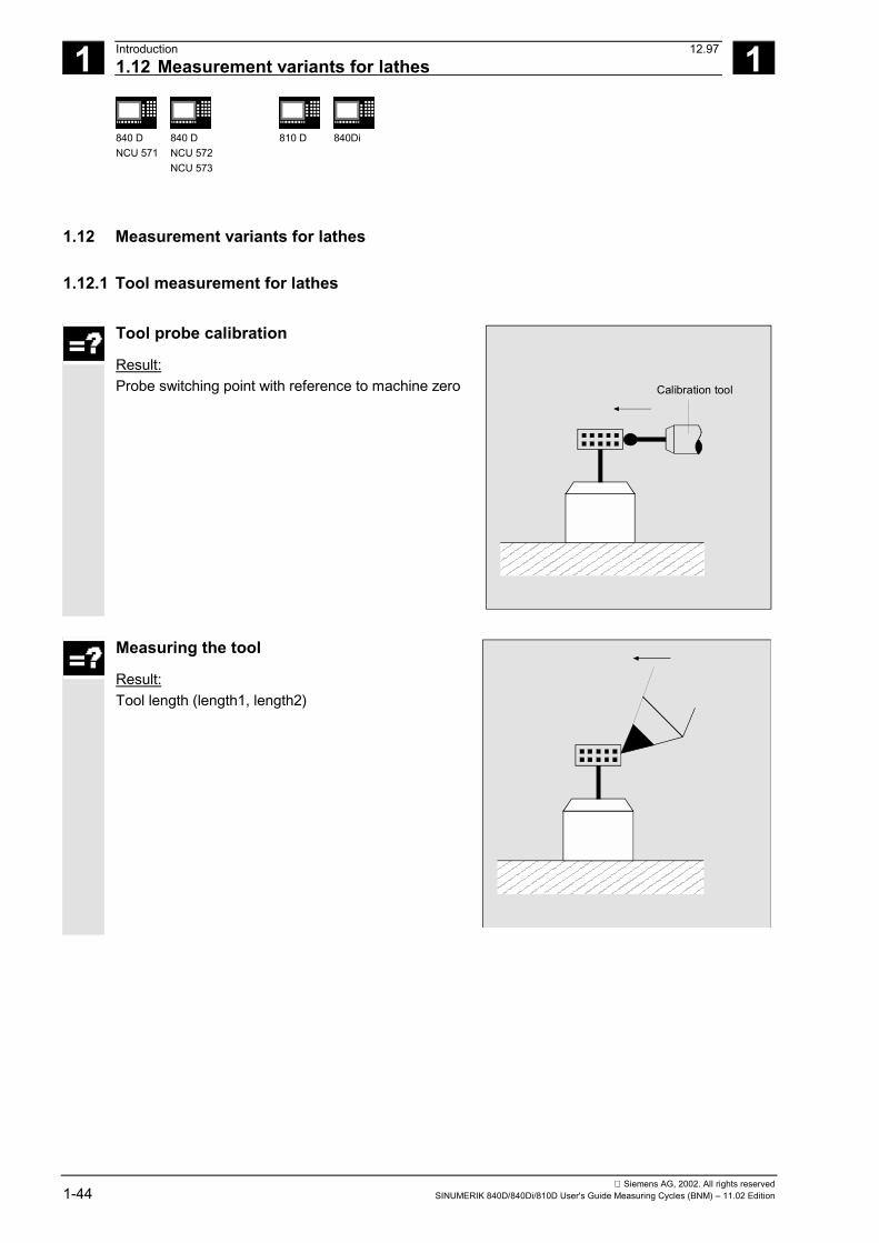
1.12.1 Tool measurement for lathes
Tool probe calibration
Result: Probe switching point with reference to machine zero
Calibration tool
Measuring the tool
Result: Tool length (length1, length2)
1 12.97 Introduction1.12 Measurement variants for lathes 1
840 DNCU 571
840 DNCU 572NCU 573
810 D 840Di
Siemens AG, 2002. All rights reservedSINUMERIK 840D/840Di/810D User's Guide Measuring Cycles (BNM) – 11.02 Edition 1-45
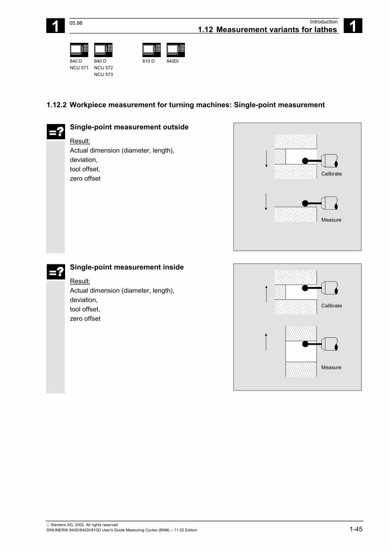
1.12.2 Workpiece measurement for turning machines: Single-point measurement
Single-point measurement outside
Result: Actual dimension (diameter, length), deviation, tool offset, zero offset
Calibrate
Measure
Single-point measurement inside
Result: Actual dimension (diameter, length), deviation, tool offset, zero offset
Calibrate
Measure
05.98
1 Introduction 12.971.12 Measurement variants for lathes 1
840 DNCU 571
840 DNCU 572NCU 573
810 D 840Di
Siemens AG, 2002. All rights reserved1-46 SINUMERIK 840D/840Di/810D User's Guide Measuring Cycles (BNM) – 11.02 Edition
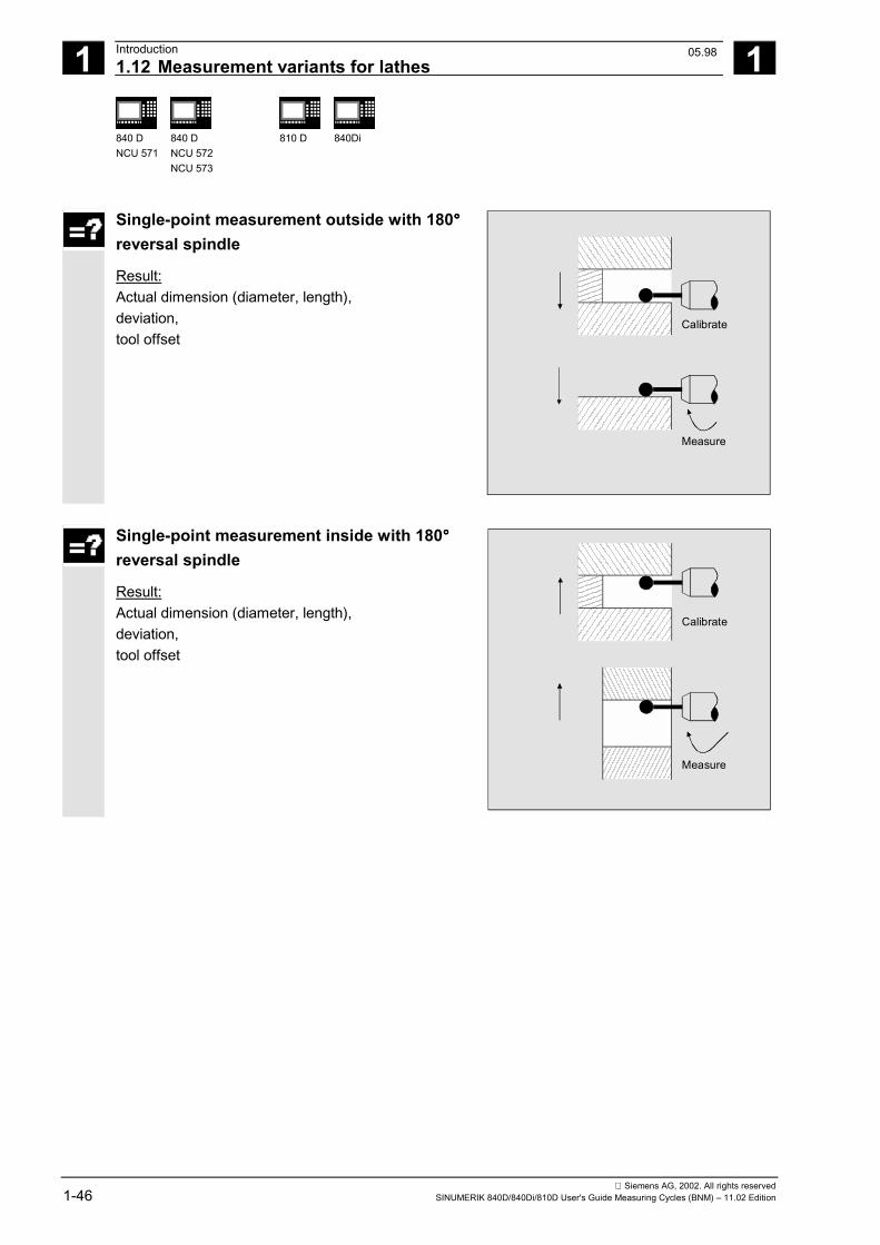
Single-point measurement outside with 180°°°°reversal spindle
Result: Actual dimension (diameter, length), deviation, tool offset
Calibrate
Measure
Single-point measurement inside with 180°°°°reversal spindle
Result: Actual dimension (diameter, length), deviation, tool offset
Calibrate
Measure
05.98
1 12.97 Introduction1.12 Measurement variants for lathes 1
840 DNCU 571
840 DNCU 572NCU 573
810 D 840Di
Siemens AG, 2002. All rights reservedSINUMERIK 840D/840Di/810D User's Guide Measuring Cycles (BNM) – 11.02 Edition 1-47
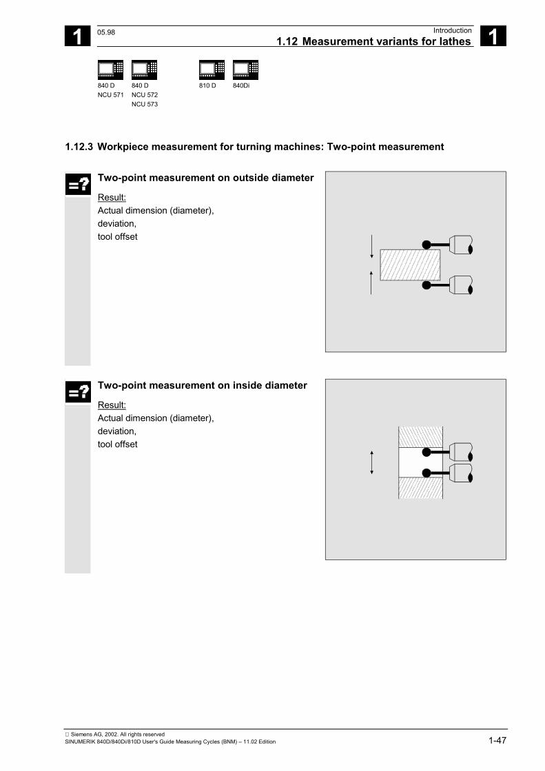
1.12.3 Workpiece measurement for turning machines: Two-point measurement
Two-point measurement on outside diameter
Result: Actual dimension (diameter), deviation, tool offset
Two-point measurement on inside diameter
Result: Actual dimension (diameter), deviation, tool offset
05.98
1 Introduction 12.971.13 Measuring cycles interface 1
840 DNCU 571
840 DNCU 572NCU 573
810 D 840Di
Siemens AG, 2002. All rights reserved1-48 SINUMERIK 840D/840Di/810D User's Guide Measuring Cycles (BNM) – 11.02 Edition
1.13 Measuring cycles interface The measuring cycles provide an interactive function for
defining input and output parameters. Values can be assigned to the input parameters via ahelp cycle in an input dialog. The results of measurement can be displayedautomatically via another help cycle.
1.13.1 Displaying measuring result screens
Function
Measuring results can be displayed automatically whilea measuring cycle is running.
Activation of this function depends on the configurationof the measuring cycle interface in the MMC and thesettings in the measuring cycle data.
Observe the specifications of the machinemanufacturer.
Depending on the configuration• the measuring result displays are automatically
deselected at the end of a measuring cycle• the measuring result displays must be
acknowledged with the NC Start key; In this case, the measuring cycle outputs the message: "Please acknowledge measuring result display withNC Start".
1 12.97 Introduction1.13 Measuring cycles interface 1
840 DNCU 571
840 DNCU 572NCU 573
810 D 840Di
Siemens AG, 2002. All rights reservedSINUMERIK 840D/840Di/810D User's Guide Measuring Cycles (BNM) – 11.02 Edition 1-49
Explanation
The measuring cycles can display different measuringresult screens depending on the measurement variant: • Tool probe calibration• Tool measurement• Workpiece probe calibration• Workpiece measurement The result displays contain the following data: Calibrating the tool probe− Measuring cycle and measurement variant− Probe ball diameter and difference− Trigger values of axis directions and differences− Positional deviation during calibration on the plane− Probe number− Safe area Tool measurement− Measuring cycle and measurement variant− Actual values and differences for tool offsets− T number and D number Calibrate tool probe− Measuring cycle and measurement variant− Trigger values of axis directions and differences− Positional deviation during calibration on the plane− Probe number− Safe area and permissible dimensional difference Workpiece measurement− Measuring cycle and measurement variant− Setpoints, actual values and their differences− Upper and lower tolerance limits− Offset value− Probe number− Safe area and permissible dimensional difference− T number and D number or ZO memory for
automatic offset
1 Introduction 12.971.13 Measuring cycles interface 1
840 DNCU 571
840 DNCU 572NCU 573
810 D 840Di
Siemens AG, 2002. All rights reserved1-50 SINUMERIK 840D/840Di/810D User's Guide Measuring Cycles (BNM) – 11.02 Edition
1.13.2 Setting parameters
Function
Values can be assigned to measuring cycle parameterswith CYCLE103.
Activation of this function depends on the configurationof the measuring cycle interface in the MMC.
Observe the specifications of the machinemanufacturer.
Explanation
When CYCLE103 is selected and started, an inputdialog for setting parameters for the measuring cycles isopened. During the course of this dialog, a series of input screenforms are opened one after the other on top of thecurrent display. Once the values have been enteredeach display must be concluded by pressing the OK keyin the vertical softkey bar. At the end of the dialog, the message "Input dialog successfully completed" is displayed in the dialog line of the control and thedisplay before dialog mode was activated isreconstructed. It is immediately possible to select and start the lastmeasuring cycle assigned parameters.
1 12.97 Introduction1.13 Measuring cycles interface 1
840 DNCU 571
840 DNCU 572NCU 573
810 D 840Di
Siemens AG, 2002. All rights reservedSINUMERIK 840D/840Di/810D User's Guide Measuring Cycles (BNM) – 11.02 Edition 1-51
Explanation
The sequence of the dialog for assigning parameters isas follows:• Selection of the measuring cycle to which
parameters are to be assigned;• Selection of the measurement variant;• Assignment of parameters for the measurement
variant chosen, this could involve several inputscreen forms depending on the measuring cycle;
• Input and confirmation of generally applicablemeasuring cycle data which do not usually change.
The input values for selecting the measuring cycle andthe measurement variant are subjected to a plausibilitycheck and the input screen forms are repeated ifnecessary.
If the operating area is switched over during the courseof the input dialog, the dialog can be selected again at alater stage with "Cycles" softkey in the extended menu.
�

1 Introduction 12.971.13 Measuring cycles interface 1
840 DNCU 571
840 DNCU 572NCU 573
810 D 840Di
Siemens AG, 2002. All rights reserved1-52 SINUMERIK 840D/840Di/810D User's Guide Measuring Cycles (BNM) – 11.02 Edition
Notes
2 12.97 Description of Parameters 2
Siemens AG, 2002. All rights reservedSINUMERIK 840D/840Di/810D User's Guide Measuring Cycles (BNM) – 11.02 Edition 2-53
Description of Parameters
2.1. Parameter concept for measuring cycles........................................................................ 2-54
2.2 Parameter overview ........................................................................................................ 2-562.2.1 Input parameters ....................................................................................................... 2-562.2.2 Result parameters..................................................................................................... 2-57
2.3 Description of the most important defining parameters .................................................. 2-582.3.1 Measurement variant: _MVAR.................................................................................. 2-582.3.2 Number of measuring axis: _MA............................................................................... 2-612.3.3 Tool number and tool name: _TNUM and _TNAME................................................. 2-622.3.4 Offset number _KNUM.............................................................................................. 2-632.3.5 Offset number _KNUM with flat D number structure ................................................ 2-652.3.6 Variable measuring speed: _VMS............................................................................. 2-662.3.7 Compensation angle position for monodirectional probe: _CORA ........................... 2-662.3.8 Tolerance parameters: _TZL, _TMV, _TUL, _TLL, _TDIF and _TSA ...................... 2-672.3.9 Multiplication factor for measurement path 2a: _FA ................................................. 2-682.3.10 Probe type/Probe number: _PRNUM........................................................................ 2-692.3.11 Empirical value/mean value: _EVNUM ..................................................................... 2-702.3.12 Multiple measurement at the same location: _NMSP ............................................... 2-712.3.13 Weighting factor k for averaging: _K......................................................................... 2-71
2.4. Description of output parameters .................................................................................... 2-722.4.1 Measuring cycle results in _OVR .............................................................................. 2-722.4.2 Measuring cycle results in _OVI................................................................................ 2-73
09.01
2 Description of Parameters 12.972.1. Parameter concept for measuring cycles 2
840 DNCU 571
840 DNCU 572NCU 573
810 D 840Di
Siemens AG, 2002. All rights reserved2-54 SINUMERIK 840D/840Di/810D User's Guide Measuring Cycles (BNM) – 11.02 Edition
2.1. Parameter concept for measuring cycles
Function
As explained at the beginning, measuring cycles aregeneral subroutines designed to solve specificmeasuring tasks. They can be adapted for this purposeby means of so-called defining parameters.
They also return data such as measurement results.They are stored in result parameters.
Furthermore, the measuring cycles also requireinternal parameters for calculations.
Defining parameters
The defining parameters of the measuring cycles aredefined as Global User Data (abbreviated to GUDs).
They are stored in the nonvolatile storage area of thecontrol such that their setting values remain stored evenwhen the control is switched off and on.
These data are contained in the data definition blocks
• GUD5.DEF and• GUD6.DEF which are supplied together with the measuring cycles.
Further notes
Many of the defining parameters have preset values.See Section 2.2
2 12.97 Description of Parameters2.1. Parameter concept for measuring cycles
2
840 DNCU 571
840 DNCU 572NCU 573
810 D
840Di
Siemens AG, 2002. All rights reservedSINUMERIK 840D/840Di/810D User's Guide Measuring Cycles (BNM) – 11.02 Edition 2-55
These blocks must be loaded into the control duringstart-up. They must then be adapted by the machinemanufacturer according to the characteristics of therelevant machine (see Part 2 Description of Functions,from Chapter 8 onwards).
Values can be assigned to these GUDs in the programor by means of keyboard inputs.
Result parameters
The results are also stored in specific GUDs.
Internal parameters
Local User Data (abbreviated to LUDs) are used in themeasuring cycles as internal arithmetic parameters. These are set up in the cycle and thus exist only for theduration of the run-time.
2 Description of Parameters 12.97 2.2 Parameter overview
2
840 DNCU 571
840 DNCU 572NCU 573
810 D
840Di
Siemens AG, 2002. All rights reserved2-56 SINUMERIK 840D/840Di/810D User's Guide Measuring Cycles (BNM) – 11.02 Edition
2.2 Parameter overview
2.2.1 Input parameters
Explanation
The defining parameters of the measuring cycles can beclassified as follows:• Mandatory parameters• Additional parameters Mandatory parameters are parameters that have to beadapted to the measuring task at hand (for example,setpoint axis, measuring axis, etc.) before each measuringcycle call. Additional parameters can generally be assigned once on amachine. They are then valid for each measuring cyclecall until they are modified by programming or operation.
All parameters with dimensions (see overview below),except for those marked 1), must be programmed in theunit of measurement of the basic system. The parametersmarked 1) must be programmed in the unit of the activesystem of units.
Mandatory parameters Parameters Type Validity Default: Meaning _SETVAL1) REAL CHAN - Setpoint _SETV[3] 1) REAL CHAN - Measure setpoint values on rectangle _ID1) REAL CHAN - Incremental infeed depth/offset _CPA1) REAL CHAN - Center point abscissa for measuring at angle _CPO1) REAL CHAN - Center point ordinate for measuring at angle _SZA1) REAL CHAN - Protection zone in abscissa _SZO1) REAL CHAN - Protection zone in ordinate _STA1 REAL CHAN 0 Initial angle _INCA REAL CHAN - Indexing angle _MVAR INT CHAN - Measurement variant _MA INT CHAN - Measuring axis _MD INT CHAN - Measuring direction _TNUM INT CHAN - T number _TNAME STRING[32] CHAN - Tool name (alternative to _TNUM in tool
management) _KNUM INT CHAN 0 Correction number (D No. or ZO No.) _RA INT CHAN - Number of rotary axis at angle measurement
12.98
2 12.97 Description of Parameters2.2 Parameter overview
2
840 DNCU 571
840 DNCU 572NCU 573
810 D
840Di
Siemens AG, 2002. All rights reservedSINUMERIK 840D/840Di/810D User's Guide Measuring Cycles (BNM) – 11.02 Edition 2-57
Auxiliary parameters Parameters Type Validity Default Meaning _VMS REAL CHAN 0 Variable measuring velocity _RF REAL CHAN 1000 Feedrate at circular-path programming _CORA REAL CHAN 0 Compensation angle for mono probe _TZL REAL CHAN 0.001 Zero offset area _TMV REAL CHAN 0.7 Mean value generation with compensation _TUL1) REAL CHAN 1.0 Upper tolerance limit _TLL1) REAL CHAN -1.0 Lower tolerance limit _TDIF REAL CHAN 1.2 Dimensions difference check _TSA REAL CHAN 2 Safe area _FA REAL CHAN 2 Measuring path multiplication factor _CM[8] REAL NCK 90, 2000, 1, 0,
0.005, 50, 4, 10 Monitoring parameters at tool measurementwith rotating spindle
_PRNUM INT CHAN 1 Probe number _EVNUM INT CHAN 0 Empirical value memory number _CALNUM INT CHAN 0 Calibration block number _NMSP INT CHAN 1 Number of measurements at the same
location _K INT CHAN 1 Weighting factor for mean value derivation
Parameters for logging only
Parameters Type Validity Meaning _PROTNAME[2] STRING[32] NCK [0]: Name of main program the log is from
[1]: Name of log file _HEADLINE[6] STRING[80] NCK 6 strings for protocol headers _PROTFORM[6] INT NCK Formatting for protocol _PROTSYM[2] CHAR NCK Separator in the protocol _PROTVAL[13] STRING[100] NCK [0, 1]: Protocol header line
[2-5]: Specification of the values to be logged [6-12]: Internal
_DIGIT INT NCK Number of decimal places
2.2.2 Result parameters Parameters Type Validity Meaning _OVR[32] REAL CHAN Result parameters: Setpoint values, actual values,
differences, offset values and others
_OVI[11] INT CHAN Result parameter, integer
12.98
2 Description of Parameters 12.97 2.3 Description of the most important defining parameters
2
840 DNCU 571
840 DNCU 572NCU 573
810 D
840Di
Siemens AG, 2002. All rights reserved2-58 SINUMERIK 840D/840Di/810D User's Guide Measuring Cycles (BNM) – 11.02 Edition
2.3 Description of the most important defining parameters
2.3.1 Measurement variant: _MVAR
Function
The measurement variant of the individual cycles isdefined in parameter _MVAR.
Parameters
Values of _MVAR The parameter can assume certain positive integers foreach measuring cycle which are listed individuallybelow.
The setting of parameter _MVAR is subjected to aplausibility check by the cycle. If it does not have adefined value, the following alarm message is output:
"Measurement variant incorrectly defined".The cycle must be interrupted by an NC RESET.
Measurement and calibration variants for workpiece measurement on milling machines
Possible values of _MVAR Measurement variants CYCLE976 0 Calibration on any surface (applicate) 1...112101 Calibrate in random hole (plane) 8...10108 Calibrate workpiece probe in any hole (plane) with
unknown position of the hole center CYCLE977 1 Measure hole and 2 Measure shaft CYCLE979 3 Measure groove 4 Measure web 101 ZO calculation in hole 102 ZO calculation in shaft 103 ZO calculation in groove 104 ZO calculation on web CYCLE977 5 Measure rectangle inside 6 Measure rectangle outside 105 ZO calculation in rectangle inside 106 ZO calculation in rectangle outside
08.99
2 12.97 Description of Parameters2.3 Description of the most important defining parameters
2
840 DNCU 571
840 DNCU 572NCU 573
810 D
840Di
Siemens AG, 2002. All rights reservedSINUMERIK 840D/840Di/810D User's Guide Measuring Cycles (BNM) – 11.02 Edition 2-59
CYCLE977 1001 Measure hole with travel around a protection zone 1002 Measure shaft while accounting for a protection zone 10031) Measure hole with contouring of a protection zone 10041) Measure web by including for a protection zone 1005 Measure rectangle inside with protection zone 1006 Measure rectangle outside with protection zone 1101 ZO calculation hole with travel around a protection zone 1102 ZO calculation of shaft while accounting for a protection
zone 11031) ZO calculation in groove with contouring of a protection
zone 11041) ZO calculation at web by including a protection zone 1105 ZO calculation in rectangle inside with protection zone 1106 ZO calculation in rectangle outside with protection zone CYCLE978 0 Measure surface 100 ZO calculation on surface 1000 Measure surface with differential measurement 1100 ZO calculation on surface with differential measurement CYCLE998 105 Angular measurement, ZO calculation 1105 Angular measurement with differential measurement, ZO
calculation
Measurement and calibration variants for toolmeasurement on milling machines
Possible values of _MVAR Measurement variants CYCLE971 1 Measure tool with motionless spindle
(Length or radius) 2 Measure tool with rotating spindle
(Length or radius) 0 Calibration of the tool probe 10000 Incremental calibration of the tool probe
Further notes
1) Measuring cycles SW 4.5 and higher
08.99
2 Description of Parameters 12.97 2.3 Description of the most important defining parameters
2
840 DNCU 571
840 DNCU 572NCU 573
810 D
840Di
Siemens AG, 2002. All rights reserved2-60 SINUMERIK 840D/840Di/810D User's Guide Measuring Cycles (BNM) – 11.02 Edition
Measurement and calibration variants for workpiece measurement on lathes
Possible values of _MVAR Measurement variants CYCLE973 0 Calibration on any surface (applicate) 13...12113 Calibration in reference groove (plane) CYCLE974 0 Single-point measurement 100 Single-point measurement ZO calculation 1000 Single-point measurement with reversal CYCLE994 1 Two-point measurement with protection zone (for inside
measurement only) 2 Two-point measurement with programmed protection
zone (for inside measurement without protection zone)
Measurement and calibration variants for toolmeasurement on lathes
Possible values of _MVAR Measurement variants CYCLE972 0 Tool probe calibration 1 Tool measurement CYCLE982
(measuringcycle SW 5.3and higher)
0 Tool probe calibration
1 Measuring turning and milling tools 2 Automatic measurement
2 12.97 Description of Parameters2.3 Description of the most important defining parameters
2
840 DNCU 571
840 DNCU 572NCU 573
810 D
840Di
Siemens AG, 2002. All rights reservedSINUMERIK 840D/840Di/810D User's Guide Measuring Cycles (BNM) – 11.02 Edition 2-61
2.3.2 Number of measuring axis: _MA
Function
The axis number (1...3) for the measuring axis in thecoordinate system must be specified via _MA (not thehardware axis number).
Parameters
Values of _MA
Measuring axis abscissa _MA = 1Measuring axis ordinate _MA = 2Measuring axis applicate _MA = 3
G17 planeY
Z
X
_MA=1
_MA=2
Axis definition in acc. to DIN 66217
_MA must be defined with offset axis /measuring axisfor certain measurement variants; in such cases, thefirst two digits contain the code for the offset axis andthe second two digits the code for the measuring axis. Example: _MA = 102 � Offset axis: 1 (abscissa) � Measuring axis: 2 (ordinate)
2 Description of Parameters 12.97 2.3 Description of the most important defining parameters
2
840 DNCU 571
840 DNCU 572NCU 573
810 D
840Di
Siemens AG, 2002. All rights reserved2-62 SINUMERIK 840D/840Di/810D User's Guide Measuring Cycles (BNM) – 11.02 Edition
2.3.3 Tool number and tool name: _TNUM and _TNAME
Function
The tool to be offset is entered during workpiecemeasurement in the parameters _TNUM and _TNAME.
The parameter _TNAME is only relevant if toolmanagement is active.
Parameters
The parameter _TNUM contains the tool number of thetool to be automatically offset during workpiecemeasurement. If tool management is active, the name of the tool canbe entered in parameter _TNAME as an alternative. Example:• without tool management:
_TNUM = 12 _TNAME = " " � is not assigned;
• with tool management:_TNUM = 0 _TNAME = "DRILL"
� the tool with the name"DRILL" is offset
or_TNUM = 13 _TNAME = " " or _TNAME="DRILL"
� the tool with the internal T number 13 is offset
In SW 4 and higher with spare tools the one is offsetwhich was last used (was in the spindle).However, the requirement is that only one tool in a groupis "active" at on time. Otherwise, the internal tool numberof the tool used must be determined and assigned to_TNUM when machining via the system variable$P_TOOLNO.
08.99
2 12.97 Description of Parameters2.3 Description of the most important defining parameters
2
840 DNCU 571
840 DNCU 572NCU 573
810 D
840Di
Siemens AG, 2002. All rights reservedSINUMERIK 840D/840Di/810D User's Guide Measuring Cycles (BNM) – 11.02 Edition 2-63
2.3.4 Offset number _KNUM
Parameters
The parameter _KNUM contains the tool offset memory number forworkpiece measurement or the specification of the zero offset to becompensated for ZO calculation.
_KNUM setting values_KNUM can accept integers with up to 6 digits, or 8 digits with flat Dnumber structures. These digits have the following significance:
1. Specification for tool offset:Structure of tool offset parameter _KNUM
6 5 4 3 2 1
D numberCurrently not assigned, i. e. = 00/1...Length compensation 2...Radius compensationNormal/inverted offset0...Normal1...InvertedOffset acc. to 4th digit1...Offset of L12...Offset of L23...Offset of L34...Radius compensation
In SW 5 and higher the last 3 digits are evaluated as a Dnumber for a value of this MD from 10...999depending on MD 18102: MM_TYPE_OF_CUTTING_EDGE =0 and MD 18105: MM_MAX_CUTTING_EDGE_NO. If thevalue is ≥1000, _KNUM is evaluated as for a flat D numberstructure.
Example:_KNUM = 12003
� D3 is corrected,� calculated as radius offset� inverted correction
11.02
2 Description of Parameters 12.97 2.3 Description of the most important defining parameters
2
840 DNCU 571
840 DNCU 572NCU 573
810 D
840Di
Siemens AG, 2002. All rights reserved2-64 SINUMERIK 840D/840Di/810D User's Guide Measuring Cycles (BNM) – 11.02 Edition
2. Specification for zero offset:_KNUM=1 ... 99 Automatic inclusion of ZO in ZO G54 ... G57 andG505...G599
In measuring cycle SW 4.4 and higher:_KNUM=1000 automatic ZO in basic frame G500 (offset always inthe last channel-specific basic frame if there are more than one).
In measuring cycle SW 6.2 and higher:- KNUM=1011...1026 automatic ZO in 1st to 16th basic frame (channel) ($P_CHBFR[0]...$P_CHBFR[15])- KNUM=1051...1066 automatic ZO in 1st to 16th basic frame (global) ($P_NCBFR[0]...$P_NCBFR[15])Note: The remaining active frame chain must be retained. WithNCU-global frames, correction for rotation is not possible.- _KNUM=2000 automatic ZO in the system frame (scratch system frame $P_SETFR)- _KNUM=9999 automatic ZO in the active frame: settable frame G54...G57, G505...G599, or G500 in the last active basic frame according to $P_CHBFRMASK (most significant bit). Note: Only here does a changed frame become active in the
cycle immediately, otherwise it is activated by the user writing G500, G54...G5xy.
The following must be set for start-up:MD 28082: MM_SYSTEM_FRAME_MASK, Bit 0=1 andBit 5=1 (system frames for scratching and cycles)
With a _KNUM setting of 0, the automatic tool offset and ZO aredeactivated.
In measuring cycle SW 6.2 and higher, CYCLE115 is introduced forthe ZO. CYCLE114 is only responsible for the tool offset.
If a fine offset is active (MD 18600: MM_FRAME_FINE_TRANS), theadditive ZO will be implemented in it (all measuring cycles with ZOexcept CYCLE961), otherwise it is implemented in the coarse offset.ZO with CYCLE961 is always in the coarse offset and any fine offsetthere may be is reset.
11.02
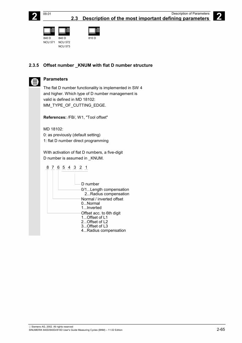
2 12.97 Description of Parameters2.3 Description of the most important defining parameters 2
840 DNCU 571
840 DNCU 572NCU 573
810 D
Siemens AG, 2002. All rights reservedSINUMERIK 840D/840Di/810D User's Guide Measuring Cycles (BNM) – 11.02 Edition 2-65
2.3.5 Offset number _KNUM with flat D number structure
Parameters
The flat D number functionality is implemented in SW 4and higher. Which type of D number management isvalid is defined in MD 18102:MM_TYPE_OF_CUTTING_EDGE.
References: /FB/, W1, "Tool offset"
MD 18102:0: as previously (default setting)1: flat D number direct programming
With activation of flat D numbers, a five-digitD number is assumed in _KNUM.
8 7 6 5 4 3
D number0/1...Length compensation 2...Radius compensationNormal / inverted offset0...Normal1...InvertedOffset acc. to 6th digit1...Offset of L12...Offset of L23...Offset of L34...Radius compensation
2 1
09.01
2 Description of Parameters 12.97 2.3 Description of the most important defining parameters
2
840 DNCU 571
840 DNCU 572NCU 573
810 D
840Di
Siemens AG, 2002. All rights reserved2-66 SINUMERIK 840D/840Di/810D User's Guide Measuring Cycles (BNM) – 11.02 Edition
2.3.6 Variable measuring speed: _VMS
Parameters
The measuring speed can be freely selected by meansof _VMS. It is specified in mm/min or inch/mindepending on the basic system.
The maximum measuring speed must be selected suchthat safe deceleration within the probe deflecting path isensured.
When _VMS = 0, then the feedrate is preset asstandard to 150 mm/min. This value is automaticallyincreased to 300 mm/min if the measuring path a(_FA > 1 ) is altered via _FA.If the basic system is in inches, 5.9055 inch/min or11.811 inch/min takes effect.
2.3.7 Compensation angle position for monodirectional probe: _CORA
Function
When using a monodirectional probe, it may benecessary for machine-specific reasons (e.g.horizontal/vertical millhead) to correct the position of theprobe to be able to carry out the measurement.
Parameters
The incorrect position can be corrected by means ofparameter _CORA. Generally speaking, _CORA is setto 90° or a multiple thereof. If the direction of rotation isaltered as a result of swiveling the milling head, then_CORA must be preset to –360° (normally 0°).
12.98
2 12.97 Description of Parameters2.3 Description of the most important defining parameters 2
840 DNCU 571
840 DNCU 572NCU 573
810 D 840Di
Siemens AG, 2002. All rights reservedSINUMERIK 840D/840Di/810D User's Guide Measuring Cycles (BNM) – 11.02 Edition 2-67
2.3.8 Tolerance parameters: _TZL, _TMV, _TUL, _TLL, _TDIF and _TSA
Some information about the tolerance parametersapplied in conjunction with measuring cycles is alreadygiven in Section 1.8.
Parameters
These parameters contain the following variables:_TZL Zero offset1)2)
_TMV Average-value generation with compensation1)
_TUL/_TLL Workpiece tolerance1)
_TDIF Dimension difference check1)2)
_TSA Safe area1) for workpiece measurement with automatic
tool offset only2) also for tool measurement
Value rangeAll of these parameters are capable of assuming anyvalue. However, only values increasing from _TZL to_TSA are meaningful. Parameters _TUL/_TLL arespecified in mm or inches depending on the activedimension system. All other parameters areprogrammed in the basic system.
2 Description of Parameters 12.97 2.3 Description of the most important defining parameters
2
840 DNCU 571
840 DNCU 572NCU 573
810 D
840Di
Siemens AG, 2002. All rights reserved2-68 SINUMERIK 840D/840Di/810D User's Guide Measuring Cycles (BNM) – 11.02 Edition
2.3.9 Multiplication factor for measurement path 2a: _FA
Parameters
Path increment a is 1 mm irrespective of the dimensionsystem, but can be increased with parameter _FA whenthe measuring cycles are called and defines thedistance from the expected position at which the probeis triggered.The maximum value for _FA is calculated as follows:
_FA Axis traversing path2max
max=
The measuring cycles automatically generate ameasurement path of 2a · _FA, which is traversed at
the measuring feedrate, i.e. at a distance of a · _FA infront of the specified setpoint position at which theprobe is actuated under ideal conditions, up toa · _FA after the anticipated setpoint position.If the probe is triggered during this measurement paththe movement is aborted with delete distance-to-go.
Example:_FA=5� Irrespective of the system of units, a measurement
path of 10 mm is generated, starting at 5 mm beforeand ending 5 mm after the specified setpoint position.
10.00
2 12.97 Description of Parameters2.3 Description of the most important defining parameters 2
840 DNCU 571
840 DNCU 572NCU 573
810 D 840Di
Siemens AG, 2002. All rights reservedSINUMERIK 840D/840Di/810D User's Guide Measuring Cycles (BNM) – 11.02 Edition 2-69
2.3.10 Probe type/Probe number: _PRNUM
Function
The data relating to the workpiece probes are stored inGUD field _WP Workpiece probe, the data relating tothe tool probes are stored in GUD field _TP Toolprobe.
The data fields _WP and _TP are configured by themachine manufacturer during start-up._PRNUM specifies the number of the selected datafield within these fields and the probe type.
Parameters
Values of _PRNUMPRNUM can assume integers of three digits. In thiscase, the first digit represents the probe type, i.e.• 0 = Multidirectional probe• 1 = Monodirectional probe. The other two digits contain the code for the probenumber.
Digit Meaning 3 2 1 - - Probe number (two digits) 0 Multiprobe probe 1 Mono probe Example of workpiece measurement:
_PRNUM = 102 � Probe type: Monodirectional
probe � Data field number: 2
Further notes
The associated field index in _WP = 1, i. e. the data ofthe _WP[1,0...9] field are considered by the measuringcycle in the calculation of the measuring results.
08.99
2 Description of Parameters 12.97 2.3 Description of the most important defining parameters
2
840 DNCU 571
840 DNCU 572NCU 573
810 D
840Di
Siemens AG, 2002. All rights reserved2-70 SINUMERIK 840D/840Di/810D User's Guide Measuring Cycles (BNM) – 11.02 Edition
2.3.11 Empirical value/mean value: _EVNUM
Function
The empirical values are used to suppress dimensionaldeviations that are not subject to a trend. The empirical and mean values themselves are storedin GUD fields _EV Empirical value and _MV Meanvalues. _EVNUM specifies the number of the empirical valuememory. The number of the mean value memory isdefined at the same time via _EVNUM. The number ofempirical and mean values is specified in the GUD field_EVMVNUM. The unit of measurement is mm in themetric basic system and inch in the inch basic system,irrespective of the active system of units.
Parameters
Values of _EVNUM The following values can be set: • = 0 Without empirical value, without mean value
memory• > 0 Empirical value memory number = mean
value memory number
If _EVNUM is defined as < 9999, the first 4 digits of_EVNUM are interpreted as the mean value memorynumber and the second 4 digits as the empirical valuememory number. Example: _EVNUM = 90012 � EV memory: 12
� MV memory: 9
Further notes
The corresponding field index in field _EV = 11 and in field _MV = 8.
12.98
2 12.97 Description of Parameters2.3 Description of the most important defining parameters 2
840 DNCU 571
840 DNCU 572NCU 573
810 D 840Di
Siemens AG, 2002. All rights reservedSINUMERIK 840D/840Di/810D User's Guide Measuring Cycles (BNM) – 11.02 Edition 2-71
2.3.12 Multiple measurement at the same location: _NMSP
Parameters
Parameter _NMSP can be used to determine thenumber of measurements at the same location. The actual/setpoint value difference D is determinedarithmetically.
DS S S
nn=
+ +1 2 ...
n...number of measurements
2.3.13 Weighting factor k for averaging: _K
Function
The weighting factor k can be applied to allow differentweighting to be given to an individual measurement. A new measurement result thus has only a limited effecton the new tool offset as a function of _K.
A detailed description is given in Section 1.7 "Measuringstrategy and compensation value definition".
2 Description of Parameters 12.97 2.4. Description of output parameters
2
840 DNCU 571
840 DNCU 572NCU 573
810 D
840Di
Siemens AG, 2002. All rights reserved2-72 SINUMERIK 840D/840Di/810D User's Guide Measuring Cycles (BNM) – 11.02 Edition
2.4. Description of output parameters
Function
In the same way as their defining parameters, themeasuring cycle results are Global User Data of themodule GUD5. In this case, the results are not stored as individualdata, but in two fields of the REAL (_OVR) andINTEGER (_OVI) types.
2.4.1 Measuring cycle results in _OVR
Function
The field _OVR[32] contains the following values:• Setpoints and actual values for abscissa, ordinate
and applicate• Lower and upper tolerance limits for the three axes• Setpoint/actual value differences in abscissa,
ordinate and applicate• Safe area• Dimensional difference• Empirical value.
The results are described individually with the relevantmeasuring cycles or measurement variants.
2 12.97 Description of Parameters2.4. Description of output parameters 2
840 DNCU 571
840 DNCU 572NCU 573
810 D 840Di
Siemens AG, 2002. All rights reservedSINUMERIK 840D/840Di/810D User's Guide Measuring Cycles (BNM) – 11.02 Edition 2-73
2.4.2 Measuring cycle results in _OVI
Function
The field _OVI[10] contains the following values: • D or ZO number• Machining plane• Measuring cycle number• Measurement variants• Weighting factor• Probe number• Mean value memory number• Empirical value memory number• Tool number• Alarm number.
The results are described individually with themeasuring cycles.
�
05.98

2 Description of Parameters 12.97 2.4. Description of output parameters
2
840 DNCU 571
840 DNCU 572NCU 573
810 D
840Di
Siemens AG, 2002. All rights reserved2-74 SINUMERIK 840D/840Di/810D User's Guide Measuring Cycles (BNM) – 11.02 Edition
Notes
3 12.97 Measuring Cycle Auxiliary Programs 3
Siemens AG, 2002. All rights reservedSINUMERIK 840D/840Di/810D User's Guide Measuring Cycles (BNM) – 11.02 Edition 3-75
Measuring Cycle Auxiliary Programs
3.1 Package structure of measuring cycles .......................................................................... 3-76
3.2 Measuring cycle subroutines........................................................................................... 3-773.2.1 CYCLE103: Parameter definition for measuring cycles........................................... 3-783.2.2 CYCLE116: Calculation of center point and radius of a circle ................................. 3-79
3.3 Measuring cycle user programs ...................................................................................... 3-813.3.1 CYCLE198: User program prior to calling measuring cycle..................................... 3-813.3.2 CYCLE199: User program at the end of a measuring cycle.................................... 3-82
3.4 Subpackages .................................................................................................................. 3-83
3 Measuring Cycle Auxiliary Programs 12.973.1 Package structure of measuring cycles 3
840 DNCU 571
840 DNCU 572NCU 573
FM-NC 810 D 840Di
Siemens AG, 2002. All rights reserved3-76 SINUMERIK 840D/840Di/810D User's Guide Measuring Cycles (BNM) – 11.02 Edition
3.1 Package structure of measuring cycles
The machine data configuration and the softwarepackage version determine which programs can beused. It is also possible to partially define theseprograms in the global cycle data during start-up.
(Please refer to data supplied by the machinemanufacturer and Installation and Start-up Guide.)
Function
The measuring cycle package supplied consists of:
• Data blocks for defining the global measuring cycledata,
• measuring cycles,• measuring cycle subroutines and• easy-to-use functions.
To ensure that the measuring cycles can be executed inthe control, the data blocks must have been loaded intodirectory "Definitions" and the measuring cycles andmeasuring cycle subroutines must be stored in the partprogram memory.
Please note that the control always requires a PowerON between loading and execution of the measuringcycles!

3 12.97 Measuring Cycle Auxiliary Programs3.2 Measuring cycle subroutines 3
840 DNCU 571
840 DNCU 572NCU 573
FM-NC 810 D 840Di
Siemens AG, 2002. All rights reservedSINUMERIK 840D/840Di/810D User's Guide Measuring Cycles (BNM) – 11.02 Edition 3-77
3.2 Measuring cycle subroutines
Function
These measuring cycle subroutines are called directlyby the cycles. With the exception of CYCLE116, thesesubroutines cannot be executed through a direct call.
Programming
Cycle Function As fromSW 4
As fromSW 4.5
In SW 6.2and higher
CYCLE100 Activate logging XCYCLE101 Deactivate logging XCYCLE102 Measured result displayCYCLE103 Parameter setting in interactive modeCYCLE104 Internal subroutine: measuring cycle interfaceCYCLE105 Internal subroutine: logging XCYCLE106 Internal subroutine: logging XCYCLE107 Output of measuring cycle messagesCYCLE108 Output of measuring cycle alarmsCYCLE109 Internal subroutine: data transfer XCYCLE110 Internal subroutine: plausibility checksCYCLE111 Internal subroutine: measuring functionsCYCLE112 Internal subroutine: measuring functionsCYCLE113 Internal subroutine: logging X
Internal subroutine: load ZO memory,load WCS wear
CYCLE114
Internal subroutine: Load WCS wear XCYCLE115 Internal subroutine: Load ZO memory XCYCLE116 Calculation of the center point and radius on a circle
CYCLE117 Internal subroutine: measuring functionsCYCLE118 Internal subroutine: logging X
11.02
3 Measuring Cycle Auxiliary Programs 12.973.2 Measuring cycle subroutines 3
840 DNCU 571
840 DNCU 572NCU 573
FM-NC 810 D 840Di
Siemens AG, 2002. All rights reserved3-78 SINUMERIK 840D/840Di/810D User's Guide Measuring Cycles (BNM) – 11.02 Edition
3.2.1 CYCLE103: Parameter definition for measuring cycles
Explanation
This auxiliary cycle controls an input dialog for assigningparameters for the measuring cycles.
It can be either directly selected and started or written inthe program before the actual measuring cycle is called.
Several input screen forms are displayed one after theother during the course of this dialog. After entering thevalues, each display must be concluded with the OKkey.
The input values for selecting the measuring cycle andthe measurement variant are checked for plausibility.As of measuring cycles SW 4.5, CYCLE103 is nolonger supported or developed further. Instead, use thecycle support for measuring cycles to supply theparameter data. Please refer to Chapter 7.2 for adetailed description.
Programming
CYCLE103
Programming example
Calibrate tool probe
CALIBRATION_IN_X_YN10 G54 G17 G0 X100 Y80 Position probe at the center of the hole and
select ZON15 T9 D1 Z10 Select tool length compensation,
position probe in the holeN20 CYCLE103 The operator can assign the parameters for
calibration cycle CYCLE976 in interactivemode
N25 CYCLE976 Measuring cycle call for calibr. in X-Y planeN50 M30 End of program
3 12.97 Measuring Cycle Auxiliary Programs3.2 Measuring cycle subroutines 3
840 DNCU 571
840 DNCU 572NCU 573
FM-NC 810 D 840Di
Siemens AG, 2002. All rights reservedSINUMERIK 840D/840Di/810D User's Guide Measuring Cycles (BNM) – 11.02 Edition 3-79
3.2.2 CYCLE116: Calculation of center point and radius of a circle
Explanation
This cycle calculates from three or four pointspositioned on one plane the circle they inscribe withcenter point and radius.
To allow this cycle to be used as universally aspossible, its data are transferred via a parameter list.
A field of REAL variables of length 13 must betransferred as the parameter.
Y
X
P1
CP
P2
P3
Radius
Calculation of circle data from 3 points
Programming
CYCLE116 (_DATE, _ALM)
Parameters
Input data_DATE [0] Number of points for calculation (3 or 4)_DATE [1] Abscissa of first point_DATE [2] Ordinate of first point_DATE [3] Abscissa of second point_DATE [4] Ordinate of second point_DATE [5] Abscissa of third point_DATE [6] Ordinate of third point_DATE [7] Abscissa of fourth point_DATE [8] Ordinate of fourth point
06.00
3 Measuring Cycle Auxiliary Programs 12.973.2 Measuring cycle subroutines 3
840 DNCU 571
840 DNCU 572NCU 573
FM-NC 810 D 840Di
Siemens AG, 2002. All rights reserved3-80 SINUMERIK 840D/840Di/810D User's Guide Measuring Cycles (BNM) – 11.02 Edition
Output dataThe results of the calculation are stored in the last fourelements of the same field:
_DATE [9] Abscissa of circle center point_DATE [10] Ordinate of circle center point_DATE [11] Circle radius_DATE [12] Status for calculation
0 Calculation in progress1 Error occurred
_ALM Error number ( 61316 or 61317 possible)
This cycle is called as a subroutine by measuring cycleCYCLE979.
Example:Circle.MPFDEF INT _ALM
DEF REAL _DATE[13]= (3,0,10,-10,0,0,-10,
0,0,0,0,0,0); 3 points specified P1:0,10
P2: -10,0P3: 0,-10
CYCLE116(_DATE, _ALM)
M0
STOPRE
M30
; Result _DATE[9]=0_DATE[10]=0_DATE[11]=10_DATE[12]=0_ALM=0
3 12.97 Measuring Cycle Auxiliary Programs3.3 Measuring cycle user programs 3
840 DNCU 571
840 DNCU 572NCU 573
FM-NC 810 D 840Di
Siemens AG, 2002. All rights reservedSINUMERIK 840D/840Di/810D User's Guide Measuring Cycles (BNM) – 11.02 Edition 3-81
3.3 Measuring cycle user programs
Function
These measuring cycle user programs are calleddirectly by the measuring cycles and can be used toprogram necessary adaptations before or after ameasurement.
3.3.1 CYCLE198: User program prior to calling measuring cycle
Explanation
This cycle is called at the start of each measuring cycle.It can be used to program necessary adaptations priorto starting measurement (e. g. activate probe, positionspindle).As delivered, this cycle contains only one CASEinstruction for a jump to a marker that corresponds tothe measuring cycle called, followed by command M17.e. g.: _M977: prior to call CYCLE977
M17 End of cycleThe user can program the necessary machineadaptations here.
09.01
3 Measuring Cycle Auxiliary Programs 12.973.3 Measuring cycle user programs 3
840 DNCU 571
840 DNCU 572NCU 573
FM-NC 810 D 840Di
Siemens AG, 2002. All rights reserved3-82 SINUMERIK 840D/840Di/810D User's Guide Measuring Cycles (BNM) – 11.02 Edition
3.3.2 CYCLE199: User program at the end of a measuring cycle
Explanation
This cycle is called at the end of each measuring cycle.It can be used to program necessary actions followingcompletion of a measurement (e. g. deactivate probe).As delivered, this cycle (just like CYCLE198) containsonly one CASE instruction for a jump to a marker thatcorresponds to the measuring cycle called, followed bycommand M17.e. g.: _M971: at the end of the CYCLE971
M17 End of cycleThe user can program the necessary machineadaptations here.
09.01
3 12.97 Measuring Cycle Auxiliary Programs3.4 Subpackages 3
840 DNCU 571
840 DNCU 572NCU 573
FM-NC 810 D 840Di
Siemens AG, 2002. All rights reservedSINUMERIK 840D/840Di/810D User's Guide Measuring Cycles (BNM) – 11.02 Edition 3-83
3.4 Subpackages
Explanation
In many application cases not all the measuring cyclesare used on one machine, instead part packages areused.The following overview shows which part packages areadvisable and executable. This allows you to savememory capacity.
Calibrate toolprobe +measure tool
Calibrate workpiece probe + measure tool +write ZO or TC
CYCLE971
CYCLE107CYCLE108CYCLE109CYCLE110CYCLE111CYCLE198CYCLE199
CYCLE961CYCLE976
CYCLE977CYCLE978CYCLE979CYCLE998
CYCLE107CYCLE108CYCLE109CYCLE110CYCLE111CYCLE112CYCLE114CYCLE116CYCLE198CYCLE199
Milling measuring cycles
Basic package
Measure tool +calibrate tool probe
Calibrate workpiece probe + measureworkpiece + write ZO or TC
CYCLE972CYCLE982CYCLE107CYCLE108CYCLE109CYCLE110CYCLE111CYCLE198CYCLE199
CYCLE973
CYCLE974CYCLE994
CYCLE107CYCLE108CYCLE109CYCLE110CYCLE111CYCLE114CYCLE117CYCLE198CYCLE199
Turning measuring cycles
Basic package
Activation: _CHBIT[10]=1
CYCLE102CYCLE104
Measurement result display selection
Activation:
CYCLE103CYCLE104
Input dialog
Call in user NC program
Additional packageOperator interface
Activation: CYCLE100
CYCLE100CYCLE101CYCLE105CYCLE106CYCLE113CYCLE118
Log in a file of the partprogram memory
Precondition:SW 4.3 in NCK
Additional package Operator interface
++
Additional packageMeasuring at milling machine in JOG mode
E_MS_CALE_MS_CANE_MS_HOL
Semi-automaticcalibration of tool probe +measure tool
Semi-automaticcalibration of tool probe,calculation and setting ofreference points
E_MS_PINE_MT_CALE_MT_LENE_MT_RAD
CYC_JMCYC_JMC
09.01

3 Measuring Cycle Auxiliary Programs 12.973.4 Subpackages 3
840 DNCU 571
840 DNCU 572NCU 573
FM-NC 810 D 840Di
Siemens AG, 2002. All rights reserved3-84 SINUMERIK 840D/840Di/810D User's Guide Measuring Cycles (BNM) – 11.02 Edition
Notes
4 06.00 Measuring in JOG 4
Siemens AG, 2002. All rights reservedSINUMERIK 840D/840Di/810D User's Guide Measuring Cycles (BNM) – 11.02 Edition 4-85
Measuring in JOG
4.1 General preconditions............................................................................................... 4-86
4.2 Workpiece measurement .......................................................................................... 4-894.2.1 Operation and function sequence of workpiece measurement ................................ 4-904.2.2 Measuring an edge ................................................................................................... 4-914.2.3 Measuring a corner ................................................................................................... 4-924.2.4 Measuring a hole....................................................................................................... 4-944.2.5 Measuring a spigot.................................................................................................... 4-954.2.6 Calibrating the measuring probe............................................................................... 4-96
4.3 Tool measurement .................................................................................................... 4-994.3.1 Operation and function sequence of tool measurement ........................................... 4-994.3.2 Tool measurement .................................................................................................... 4-994.3.3 Calibrating the tool measuring probe ...................................................................... 4-101
4 Measuring in JOG 06.004.1 General preconditions 4
840 DNCU 572NCU 573
810D 840Di
Siemens AG, 2002. All rights reserved4-86 SINUMERIK 840D/840Di/810D User's Guide Measuring Cycles (BNM) – 11.02 Edition
4.1 General preconditions
Certain preconditions must be fulfilled beforemeasuring in JOG can be used.These conditions are described in greater detail in Part2 Description of Functions (from Chapter 8 onwards).
The following checklist is useful in determiningwhether all such preconditions are fulfilled:
Machine• All machine axes are designed in accordance
with DIN 66217.• A touch-trigger probe (3D) is provided for acquiring
workpiece dimensions, and a touch-trigger toolprobe for acquiring tool dimensions.(see also Section 1.4 Suitable probe types)
• The reference points have been approached.
Control• 840D as of NCU 572 with SW 5.3 and higher,
810D SW 3.3 and higherMMC103 SW 5.3 and higher
Machine data for running machine cycles:• All machine data listed in Section 10.1 meet the
minimum requirements for running measuringcycles.
Machine data for measuring in JOG• Machine data
– MD 11602: ASUB_START_MASK– MD 11604: ASUB_START_PRIO_LEVEL– MD 20110: RESET_MODE_MASK– MD 20112: START_MODE_MASKare set as specified in the detailed functiondescription (see Subsection 10.3.1).
Notice: Interrupt number 8 is used to start theASUBs for measuring in JOG and must thereforenot be used by the user.
09.01
4 06.00 Measuring in JOG4.1 General preconditions 4
Siemens AG, 2002. All rights reservedSINUMERIK 840D/840Di/810D User's Guide Measuring Cycles (BNM) – 11.02 Edition 4-87
Availability of measuring cycles• The data blocks:
GUD5.DEF andGUD6.DEF
in directory DEFINE on diskette 1 have been loadedin the control (directory "Definitions" in the filesystem) and
• the measuring cycles in directory CYCLES ondiskette 1 have been loaded into the standard cycledirectory of the control and then a power-onexecuted.
Availability of JOG measuring files• All files in directory JOG_MESS on diskette 2 have
been loaded into the control via "Data in" and apower-on then executed.
Adaptation of data block GUD7.DEF:Data block GUD7.DEF has been adapted to therequirements of measuring in JOG as specified in thedetailed function description (see Subsection 10.3.1).
Function
MEASURING IN JOG comprises the following functions:
• Semi-automatic calculation of tool lengths and storage in tool offsetmemory.
• Semi-automatic calculation and setting of reference points and storagein zero offset memory.
The functions are operated with softkeys and input displays. Themeasuring operation is canceled with RESET.
NoticeMake sure that you select the correct channel, as the functionMEASURING IN JOG operates channel dependently. Selecting the wrongchannel when the measuring operation is active could destroy themeasuring probe.
The measuring function is selected via the softkey bar in the JOG basicdisplay.
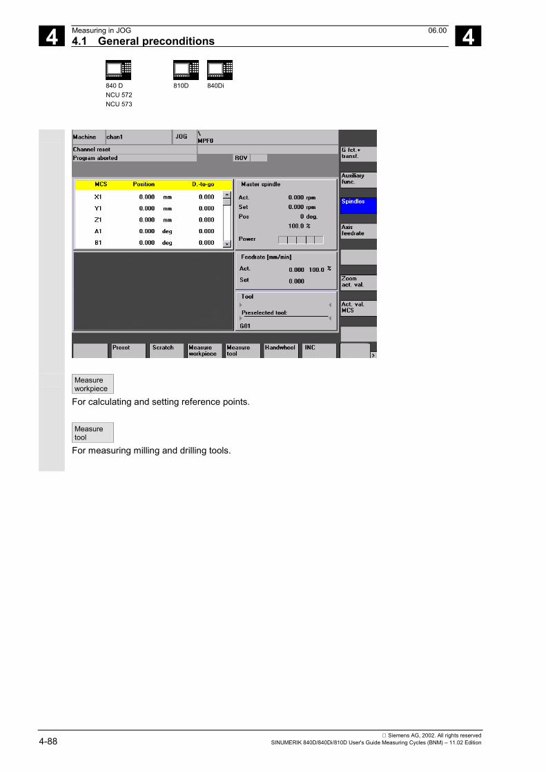
4 Measuring in JOG 06.004.1 General preconditions 4
840 DNCU 572NCU 573
810D 840Di
Siemens AG, 2002. All rights reserved4-88 SINUMERIK 840D/840Di/810D User's Guide Measuring Cycles (BNM) – 11.02 Edition
Measureworkpiece
For calculating and setting reference points.
Measuretool
For measuring milling and drilling tools.
4 06.00 Measuring in JOG4.2 Workpiece measurement 4
840 DNCU 572NCU 573
810D 840Di
Siemens AG, 2002. All rights reservedSINUMERIK 840D/840Di/810D User's Guide Measuring Cycles (BNM) – 11.02 Edition 4-89
4.2 Workpiece measurement
Function
With this function you can set reference points onthe workpiece using a workpiece probe on themachine.
You call a measuring cycle to set up a workpiece that isclamped on the table. This measuring cycleautomatically generates the measurement paths andintermediate positions as a function of the specifiedsetpoints. While the measuring cycle is running, thebasic offset defined via GUD6 or a settable ZO, as wellas a further working plane G17...G19 set in GUD6 dataare effective. The GUD6 data also specifies which datafield is assigned to the measuring probe in the spindleand the measuring probe type (multiprobe ormonoprobe) (the parameters for switching behaviorfound by calibrating the measuring probe are alsostored in this data field).All the measuring points required for the measurementtask are approached. Prepositioning can either beperformed manually or in a program.
When measurement is complete, the result (corner,center point of hole/spigot, edge) is automaticallycalculated in the measuring cycle according to the typeof measurement, and the reference point is set withreference to the basic frame or a settable zero offsetaccording to the selection made by correcting the zerooffset memory in question. If "Off" is selected, nocorrection is made.
Precondition• The workpiece probe is located in the spindle and
has been calibrated.
09.01
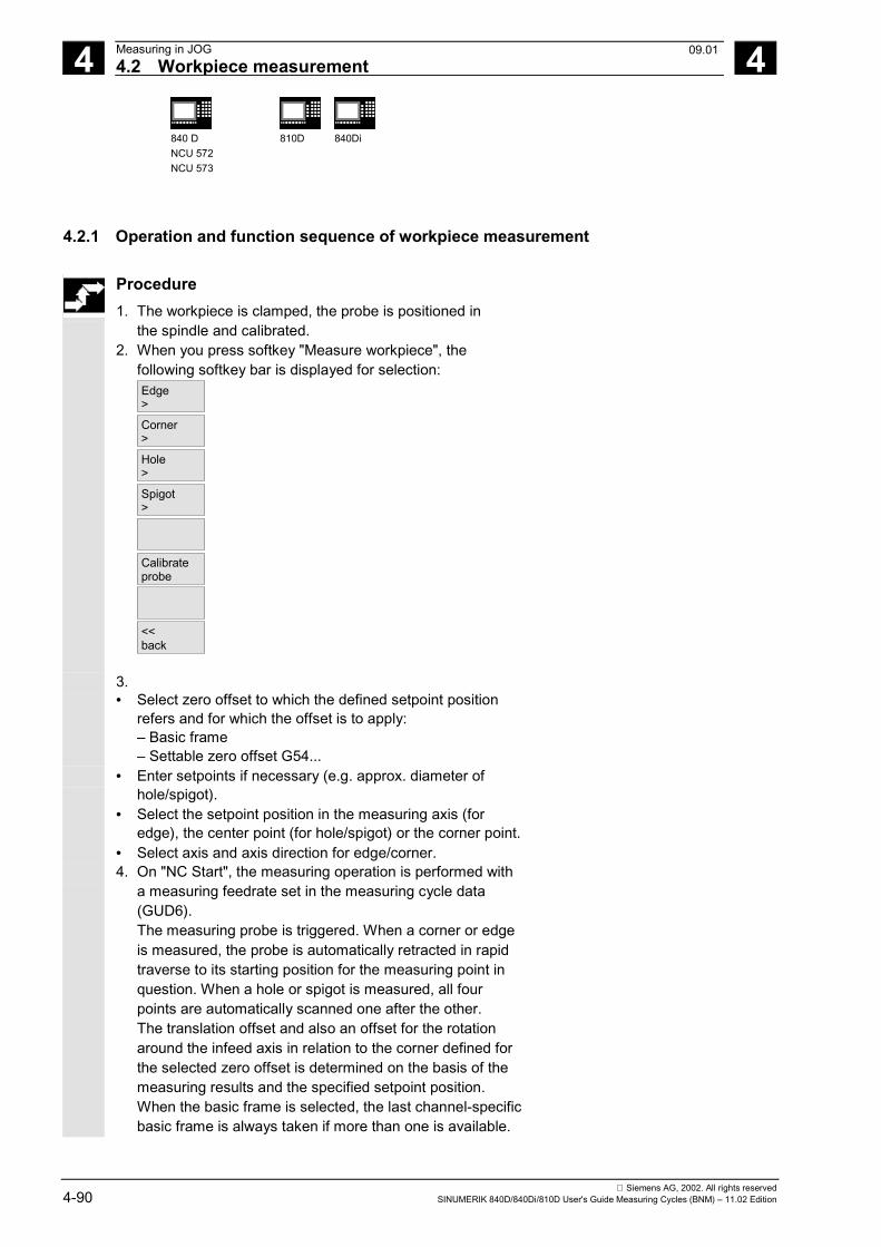
4 Measuring in JOG 06.004.2 Workpiece measurement 4
840 DNCU 572NCU 573
810D 840Di
Siemens AG, 2002. All rights reserved4-90 SINUMERIK 840D/840Di/810D User's Guide Measuring Cycles (BNM) – 11.02 Edition
4.2.1 Operation and function sequence of workpiece measurement
Procedure1. The workpiece is clamped, the probe is positioned in
the spindle and calibrated.2. When you press softkey "Measure workpiece", the
following softkey bar is displayed for selection:Edge>
Corner>
Hole>
Spigot>
Calibrateprobe
<<back
3. • Select zero offset to which the defined setpoint position
refers and for which the offset is to apply:– Basic frame– Settable zero offset G54...
• Enter setpoints if necessary (e.g. approx. diameter ofhole/spigot).
• Select the setpoint position in the measuring axis (foredge), the center point (for hole/spigot) or the corner point.
• Select axis and axis direction for edge/corner.4. On "NC Start", the measuring operation is performed with
a measuring feedrate set in the measuring cycle data(GUD6).The measuring probe is triggered. When a corner or edgeis measured, the probe is automatically retracted in rapidtraverse to its starting position for the measuring point inquestion. When a hole or spigot is measured, all fourpoints are automatically scanned one after the other.The translation offset and also an offset for the rotationaround the infeed axis in relation to the corner defined forthe selected zero offset is determined on the basis of themeasuring results and the specified setpoint position.When the basic frame is selected, the last channel-specificbasic frame is always taken if more than one is available.
09.01
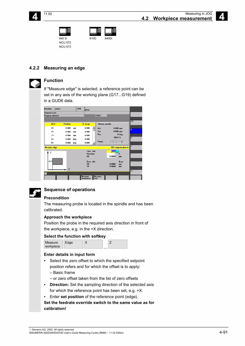
4 06.00 Measuring in JOG4.2 Workpiece measurement 4
840 DNCU 572NCU 573
810D 840Di
Siemens AG, 2002. All rights reservedSINUMERIK 840D/840Di/810D User's Guide Measuring Cycles (BNM) – 11.02 Edition 4-91
4.2.2 Measuring an edge
Function
If "Measure edge" is selected, a reference point can beset in any axis of the working plane (G17...G19) definedin a GUD6 data.
Sequence of operations
PreconditionThe measuring probe is located in the spindle and has beencalibrated.
Approach the workpiecePosition the probe in the required axis direction in front ofthe workpiece, e.g. in the +X direction.
Select the function with softkeyMeasureworkpiece
Edge
X ...
Z
Enter details in input form• Select the zero offset to which the specified setpoint
position refers and for which the offset is to apply:– Basic frame– or zero offset taken from the list of zero offsets
• Direction: Set the sampling direction of the selected axisfor which the reference point has been set, e.g. +X.
• Enter set position of the reference point (edge).Set the feedrate override switch to the same value as forcalibration!
11.02
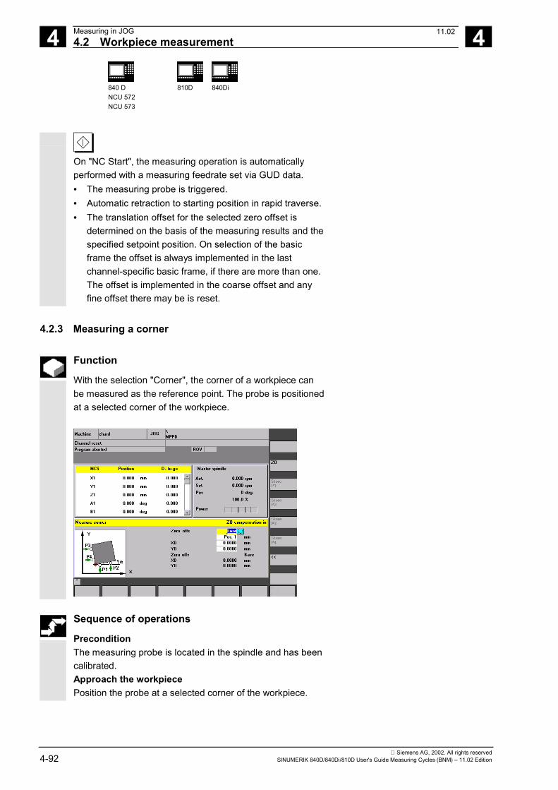
4 Measuring in JOG 06.004.2 Workpiece measurement 4
840 DNCU 572NCU 573
810D 840Di
Siemens AG, 2002. All rights reserved4-92 SINUMERIK 840D/840Di/810D User's Guide Measuring Cycles (BNM) – 11.02 Edition
On "NC Start", the measuring operation is automaticallyperformed with a measuring feedrate set via GUD data.• The measuring probe is triggered.• Automatic retraction to starting position in rapid traverse.• The translation offset for the selected zero offset is
determined on the basis of the measuring results and thespecified setpoint position. On selection of the basicframe the offset is always implemented in the lastchannel-specific basic frame, if there are more than one.The offset is implemented in the coarse offset and anyfine offset there may be is reset.
4.2.3 Measuring a corner
Function
With the selection "Corner", the corner of a workpiece canbe measured as the reference point. The probe is positionedat a selected corner of the workpiece.
Sequence of operations
PreconditionThe measuring probe is located in the spindle and has beencalibrated.Approach the workpiecePosition the probe at a selected corner of the workpiece.
11.02
4 06.00 Measuring in JOG4.2 Workpiece measurement 4
840 DNCU 572NCU 573
810D 840Di
Siemens AG, 2002. All rights reservedSINUMERIK 840D/840Di/810D User's Guide Measuring Cycles (BNM) – 11.02 Edition 4-93
Select the function with softkeyMeasureworkpiece
Corner
Enter details in input form• Select the zero offset to which the specified
setpoint position for the corner refers and for whichthe offset is to apply:– Basic frame– or zero offset taken from the list of zero offsets
• Position: Set the corner to be used as the referencepoint.
• Enter set position of the reference point (corner).
Approach sampling pointPosition the probe at the first sampling point P1 of theworkpiece edge.Set the feedrate override switch to the same valueas for calibration!
On "NC Start", the measuring operation is automaticallyperformed with a measuring feedrate set via GUD data.• The measuring probe is triggered.• Automatic retraction to starting position in rapid
traverse.
Store the position values of sampling point P1 bypressing softkey "Save P1". Repeat the procedure"approach sampling points" for sampling points P2...P4 inthe same way.
Calculatecorner
Press softkey "Calculate corner" to calculate thetranslation offset and the rotational offset around theinfeed axis for the selected zero offset. On selection ofthe basic frame the offset is always implemented in thelast channel-specific basic frame, if there are more thanone. The offset is implemented in the coarse offset andany fine offset there may be is reset.• The order in which sampling points P1...P4 are
approached must be maintained.On a rectangular workpiece, three sampling points aresufficient for the calculation.
11.02
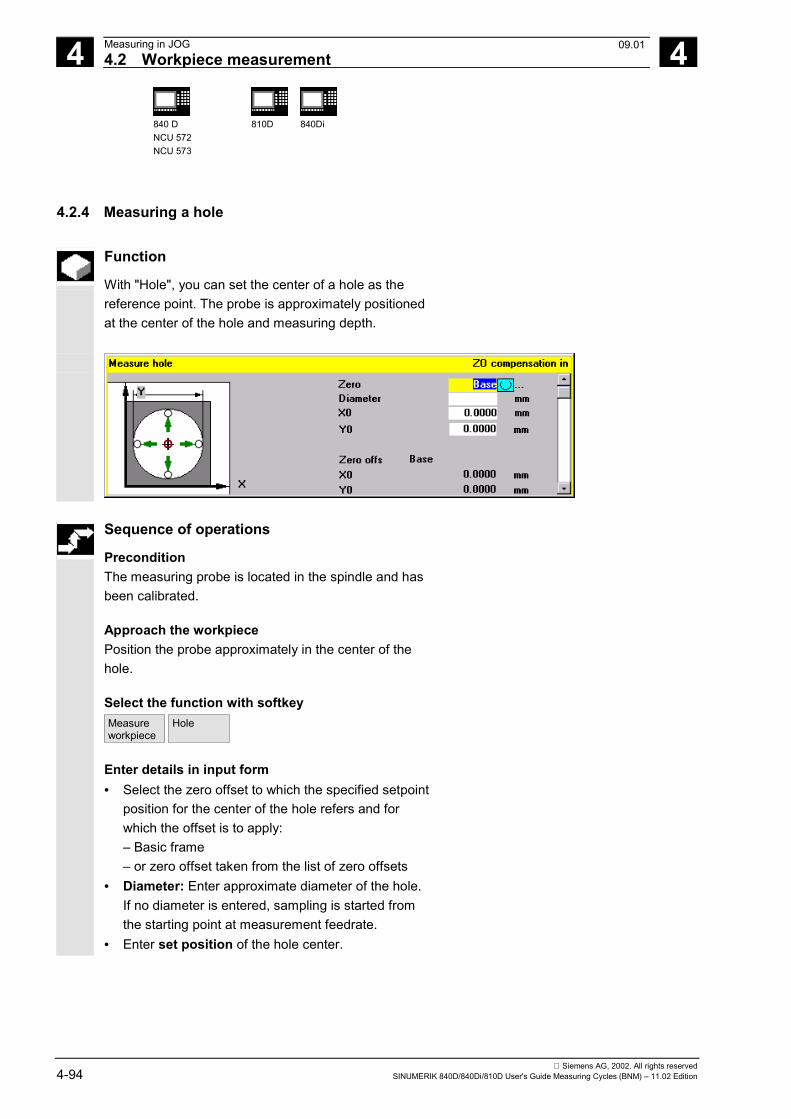
4 Measuring in JOG 06.004.2 Workpiece measurement 4
840 DNCU 572NCU 573
810D 840Di
Siemens AG, 2002. All rights reserved4-94 SINUMERIK 840D/840Di/810D User's Guide Measuring Cycles (BNM) – 11.02 Edition
4.2.4 Measuring a hole
Function
With "Hole", you can set the center of a hole as thereference point. The probe is approximately positionedat the center of the hole and measuring depth.
Sequence of operations
PreconditionThe measuring probe is located in the spindle and hasbeen calibrated.
Approach the workpiecePosition the probe approximately in the center of thehole.
Select the function with softkeyMeasureworkpiece
Hole
Enter details in input form• Select the zero offset to which the specified setpoint
position for the center of the hole refers and forwhich the offset is to apply:– Basic frame– or zero offset taken from the list of zero offsets
• Diameter: Enter approximate diameter of the hole.If no diameter is entered, sampling is started fromthe starting point at measurement feedrate.
• Enter set position of the hole center.
09.01
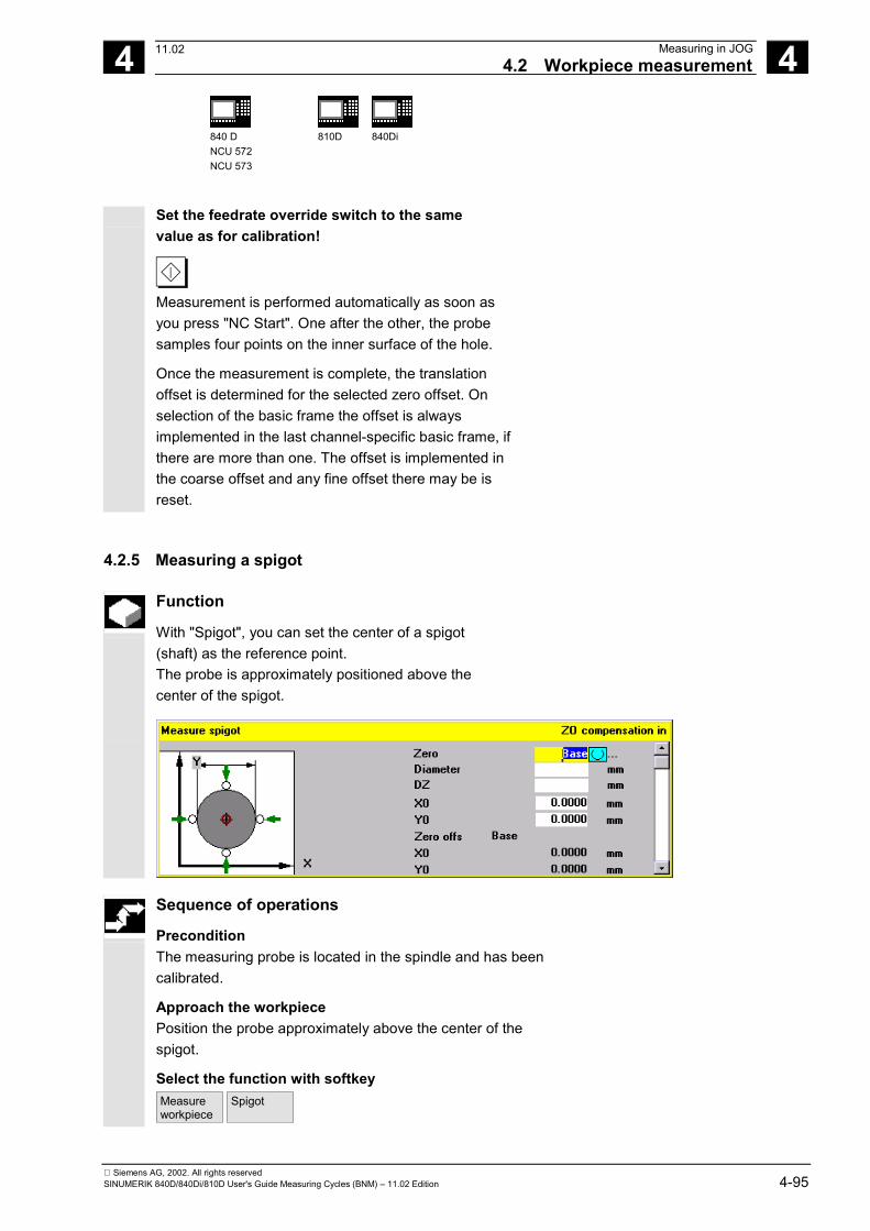
4 06.00 Measuring in JOG4.2 Workpiece measurement 4
840 DNCU 572NCU 573
810D 840Di
Siemens AG, 2002. All rights reservedSINUMERIK 840D/840Di/810D User's Guide Measuring Cycles (BNM) – 11.02 Edition 4-95
Set the feedrate override switch to the samevalue as for calibration!
Measurement is performed automatically as soon asyou press "NC Start". One after the other, the probesamples four points on the inner surface of the hole.
Once the measurement is complete, the translationoffset is determined for the selected zero offset. Onselection of the basic frame the offset is alwaysimplemented in the last channel-specific basic frame, ifthere are more than one. The offset is implemented inthe coarse offset and any fine offset there may be isreset.
4.2.5 Measuring a spigot
Function
With "Spigot", you can set the center of a spigot(shaft) as the reference point.The probe is approximately positioned above thecenter of the spigot.
Sequence of operations
PreconditionThe measuring probe is located in the spindle and has beencalibrated.
Approach the workpiecePosition the probe approximately above the center of thespigot.
Select the function with softkeyMeasureworkpiece
Spigot
11.02
4 Measuring in JOG 06.004.2 Workpiece measurement 4
840 DNCU 572NCU 573
810D 840Di
Siemens AG, 2002. All rights reserved4-96 SINUMERIK 840D/840Di/810D User's Guide Measuring Cycles (BNM) – 11.02 Edition
Enter details in input form• Select the zero offset to which the specified setpoint
position for the center of the spigot refers and for whichthe offset is to apply:– Basic frame– or zero offset taken from the list of zero offsets
• Diameter: Specify the approximate spigot diameter(check diameter>0, safety clearance, include probeoffsets).
• Specify set position of the center of the spigot.• Enter measurement infeed.Set the feedrate override switch to the same value as forcalibration!
Measurement is performed automatically as soon as youpress "NC Start". One after the other, the probe samplesfour points on the outside of the spigot.
Once the measurement is complete, the translation offset isdetermined for the selected zero offset. On selection of thebasic frame the offset is always implemented in the lastchannel-specific basic frame, if there are more than one.The offset is implemented in the coarse offset and any fineoffset there may be is reset.
4.2.6 Calibrating the measuring probe
Function
With milling machines and machining centers, theprobe is usually loaded into the spindle from a toolmagazine. This may result in errors when furthermeasurements are taken on account of probe clampingtolerances in the spindle.In addition, the trigger point must be preciselydetermined in relation to the spindle center. This isperformed by the calibration cycle with which it ispossible to calibrate the measuring probe either in anyhole or on a surface.The type of calibration is selected with softkeys"Length" and "Radius".
11.02
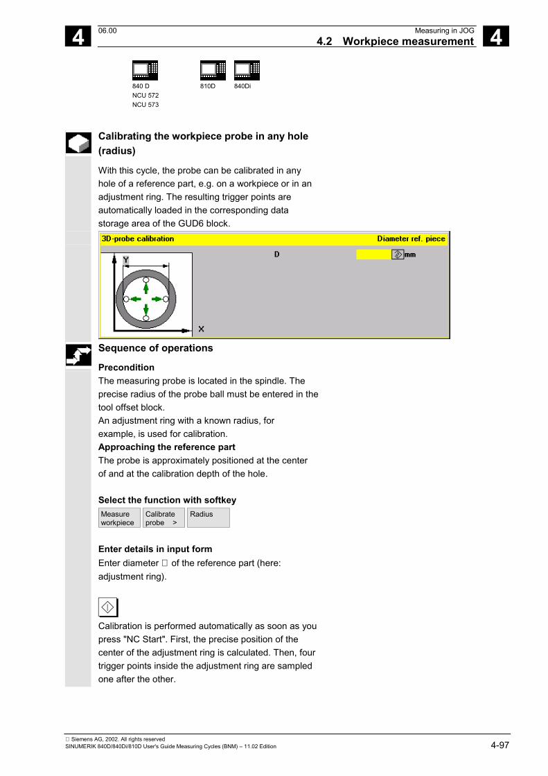
4 06.00 Measuring in JOG4.2 Workpiece measurement 4
840 DNCU 572NCU 573
810D 840Di
Siemens AG, 2002. All rights reservedSINUMERIK 840D/840Di/810D User's Guide Measuring Cycles (BNM) – 11.02 Edition 4-97
Calibrating the workpiece probe in any hole(radius)
With this cycle, the probe can be calibrated in anyhole of a reference part, e.g. on a workpiece or in anadjustment ring. The resulting trigger points areautomatically loaded in the corresponding datastorage area of the GUD6 block.
Sequence of operations
PreconditionThe measuring probe is located in the spindle. Theprecise radius of the probe ball must be entered in thetool offset block.An adjustment ring with a known radius, forexample, is used for calibration.Approaching the reference partThe probe is approximately positioned at the centerof and at the calibration depth of the hole.
Select the function with softkeyMeasureworkpiece
Calibrateprobe >
Radius
Enter details in input formEnter diameter ∅ of the reference part (here:adjustment ring).
Calibration is performed automatically as soon as youpress "NC Start". First, the precise position of thecenter of the adjustment ring is calculated. Then, fourtrigger points inside the adjustment ring are sampledone after the other.
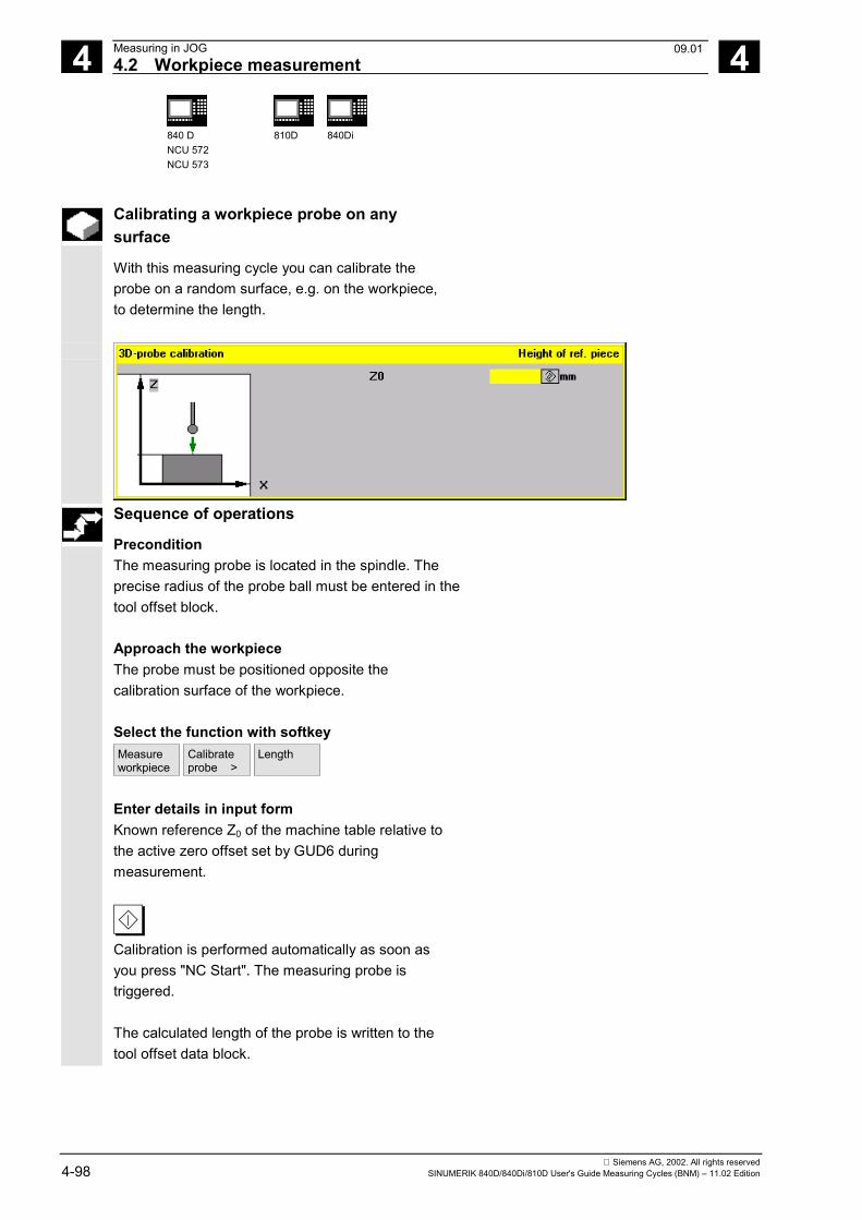
4 Measuring in JOG 06.004.2 Workpiece measurement 4
840 DNCU 572NCU 573
810D 840Di
Siemens AG, 2002. All rights reserved4-98 SINUMERIK 840D/840Di/810D User's Guide Measuring Cycles (BNM) – 11.02 Edition
Calibrating a workpiece probe on anysurface
With this measuring cycle you can calibrate theprobe on a random surface, e.g. on the workpiece,to determine the length.
Sequence of operations
PreconditionThe measuring probe is located in the spindle. Theprecise radius of the probe ball must be entered in thetool offset block.
Approach the workpieceThe probe must be positioned opposite thecalibration surface of the workpiece.
Select the function with softkeyMeasureworkpiece
Calibrateprobe >
Length
Enter details in input formKnown reference Z0 of the machine table relative tothe active zero offset set by GUD6 duringmeasurement.
Calibration is performed automatically as soon asyou press "NC Start". The measuring probe istriggered.
The calculated length of the probe is written to thetool offset data block.
09.01
4 06.00 Measuring in JOG4.3 Tool measurement 4
840 DNCU 572NCU 573
810D 840Di
Siemens AG, 2002. All rights reservedSINUMERIK 840D/840Di/810D User's Guide Measuring Cycles (BNM) – 11.02 Edition 4-99
4.3 Tool measurement
Function
Tools can be measured in the machine with thisfunction.The tool lengths are automatically written to a tooloffset memory and are therefore immediately availablefor workpiece machining directly after measurement.
General preconditions• The reference points have been approached.• The tool measuring probe is swung in or
inserted.• The tool probe has been calibrated.• The tool to be measured is located in the spindle.• The tool geometry data (length and radius) have
been entered in the tool offset data block asapproximate values.
• The tool must be prepositioned in such a way thatcollision-free approach to the tool measuring probeis possible.
4.3.1 Operation and function sequence of tool measurement
Procedure
1. The tool is replaced or inserted manually.2. When you press softkey "Measure tool", the following
selection appears on the softkey bar:
Length>
Diameter>
Calibrateprobe
<<back
3. Enter the measurement type and enter thevalues in the input form.
4. Position the tool near the tool measuring probe withthe JOG direction keys.
5. Start the measuring procedure with "NC-Start".
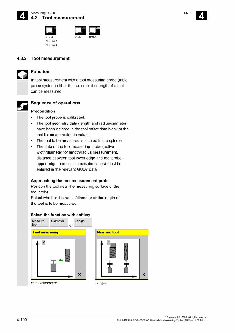
4 Measuring in JOG 06.004.3 Tool measurement 4
840 DNCU 572NCU 573
810D 840Di
Siemens AG, 2002. All rights reserved4-100 SINUMERIK 840D/840Di/810D User's Guide Measuring Cycles (BNM) – 11.02 Edition
4.3.2 Tool measurement
Function
In tool measurement with a tool measuring probe (tableprobe system) either the radius or the length of a toolcan be measured.
Sequence of operations
Precondition• The tool probe is calibrated.• The tool geometry data (length and radius/diameter)
have been entered in the tool offset data block of thetool list as approximate values.
• The tool to be measured is located in the spindle.• The data of the tool measuring probe (active
width/diameter for length/radius measurement,distance between tool lower edge and tool probeupper edge, permissible axis directions) must beentered in the relevant GUD7 data.
Approaching the tool measurement probePosition the tool near the measuring surface of thetool probe.Select whether the radius/diameter or the length ofthe tool is to be measured.
Select the function with softkeyMeasuretool
Diameter or
Length
Radius/diameter Length
4 06.00 Measuring in JOG4.3 Tool measurement 4
840 DNCU 572NCU 573
810D 840Di
Siemens AG, 2002. All rights reservedSINUMERIK 840D/840Di/810D User's Guide Measuring Cycles (BNM) – 11.02 Edition 4-101
Enter details in input form• Enter length offset V (positive value), required, for
example, for milling with ballhead cutters or millswith tool inserts.
Measurement is performed automatically as soon asyou press "NC Start".The tool geometry data radius and length arecalculated and written to the tool list.
4.3.3 Calibrating the tool measuring probe
Function
Mechanical tool measuring probes are typically shapedlike a cube or a cylindrical disk. The probe is fixed inthe machining range of the machine (on the machinetable) and must be aligned relative to the machiningaxes.
The function "Calibrate tool measuring probe"calculates the current distance between machine zeroand the tool measuring probe using the calibration tooland automatically writes them to an internal datastorage area. 120 (mill) can be entered as the tool type,there is no special calibration tool type.
Sequence of operations
Precondition• The exact length and radius of the calibration tool
must be stored in a tool offset data block.• The calibration tool is located in the spindle.• The data of the tool measuring probe (active
width/diameter for length/radius measurement,distance between tool lower edge and tool probeupper edge, permissible axis directions) must beentered in the relevant GUD7 data.
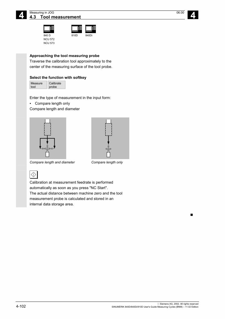
4 Measuring in JOG 06.004.3 Tool measurement 4
840 DNCU 572NCU 573
810D 840Di
Siemens AG, 2002. All rights reserved4-102 SINUMERIK 840D/840Di/810D User's Guide Measuring Cycles (BNM) – 11.02 Edition
Approaching the tool measuring probeTraverse the calibration tool approximately to thecenter of the measuring surface of the tool probe.
Select the function with softkeyMeasuretool
Calibrateprobe
Enter the type of measurement in the input form:• Compare length onlyCompare length and diameter
Compare length and diameter Compare length only
Calibration at measurement feedrate is performedautomatically as soon as you press "NC Start".The actual distance between machine zero and the toolmeasurement probe is calculated and stored in aninternal data storage area.
�
5 12.97 Measuring Cycles for Milling and Machining Centers 5
Siemens AG, 2002. All rights reservedSINUMERIK 840D/840Di/810D User's Guide Measuring Cycles (BNM) – 11.02 Edition 5-103
Measuring Cycles for Milling and Machining Centers
5.1 General preconditions ................................................................................................... 5-104
5.2 CYCLE971 Tool measuring for milling tools ................................................................. 5-1065.2.1 CYCLE971 Measuring strategy.............................................................................. 5-1085.2.2 CYCLE971 Calibrate tool probe............................................................................. 5-1105.2.3 CYCLE971 Measure tool ....................................................................................... 5-114
5.3 CYCLE976 Calibrate workpiece probe.......................................................................... 5-1195.3.1 CYCLE976 Calibrate workpiece probe in any hole (plane) with known hole
center ..................................................................................................................... 5-1225.3.2 CYCLE976 Calibrate workpiece probe in any hole (plane) with unknown
hole center (measuring cycles SW 4.4 and higher) ............................................... 5-1245.3.3 CYCLE976 Calibrate workpiece probe on a random surface ................................ 5-1265.3.4 Calibrate workpiece probe in applicate with calculation of probe length
(measuring cycles SW 4.4. and higher)................................................................. 5-128
5.4 CYCLE977 Workpiece measurement: Hole/shaft/groove/web/rectangle (paraxial) ..... 5-1305.4.1 CYCLE977 Measure hole, shaft, groove, web, rectangle ...................................... 5-1345.4.2 CYCLE977 ZO calculation in hole, shaft, groove, web, rectangle ......................... 5-140
5.5 CYCLE978 Workpiece measurement: Surface ............................................................ 5-1465.5.1 CYCLE978 ZO calculation on a surface (single point measuring cycle)................ 5-1495.5.2 CYCLE978 Single-point measurement .................................................................. 5-152
5.6 CYCLE979 Workpiece measurement: Hole/shaft/groove/web (at a random angle)..... 5-1565.6.1 CYCLE979 Measure hole, shaft, groove, web....................................................... 5-1595.6.2 CYCLE979 ZO calculation in hole, shaft, groove, web .......................................... 5-164
5.7 CYCLE998 Angular measurement (ZO calculation) ..................................................... 5-169
5.8 CYCLE961 Automatic setup of inside and outside corner ............................................ 5-1805.8.1 Automatic setup of corner with distances and angles specified ............................ 5-1805.8.2 Automatic setup of corner by defining 4 points (measuring cycles SW 4.5
and higher) ............................................................................................................. 5-185
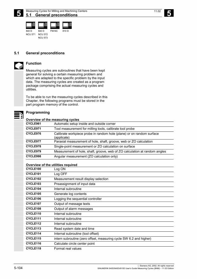
5 Measuring Cycles for Milling and Machining Centers 12.975.1 General preconditions 5
840 DNCU 571
840 DNCU 572NCU 573
FM-NC 810 D
Siemens AG, 2002. All rights reserved5-104 SINUMERIK 840D/840Di/810D User's Guide Measuring Cycles (BNM) – 11.02 Edition
5.1 General preconditions
Function
Measuring cycles are subroutines that have been keptgeneral for solving a certain measuring problem andwhich are adapted to the specific problem by the inputdata. The measuring cycles are created as a programpackage comprising the actual measuring cycles andutilities.
To be able to run the measuring cycles described in thisChapter, the following programs must be stored in thepart program memory of the control.
Programming
Overview of the measuring cyclesCYCLE961 Automatic setup inside and outside cornerCYCLE971 Tool measurement for milling tools, calibrate tool probeCYCLE976 Calibrate workpiece probe in random hole (plane) or on random surface
(applicate)CYCLE977 Paraxial measurement of hole, shaft, groove, web or ZO calculationCYCLE978 Single-point measurement or ZO calculation on surfaceCYCLE979 Measurement of hole, shaft, groove, web of ZO calculation at random anglesCYCLE998 Angular measurement (ZO calculation only)
Overview of the utilities requiredCYCLE100 Log ONCYCLE101 Log OFFCYCLE102 Measurement result display selectionCYCLE103 Preassignment of input dataCYCLE104 Internal subroutineCYCLE105 Generate log contentsCYCLE106 Logging the sequential controllerCYCLE107 Output of message textsCYCLE108 Output of alarm messagesCYCLE110 Internal subroutineCYCLE111 Internal subroutineCYCLE112 Internal subroutineCYCLE113 Read system date and timeCYCLE114 Internal subroutine (tool offset)CYCLE115 intern subroutine (zero offset, measuring cycle SW 6.2 and higher)CYCLE116 Calculate circle center pointCYCLE118 Format real values
11.02
5 12.97 Measuring Cycles for Milling and Machining Centers5.1 General preconditions 5
840 DNCU 571
840 DNCU 572NCU 573
810 D
Siemens AG, 2002. All rights reservedSINUMERIK 840D/840Di/810D User's Guide Measuring Cycles (BNM) – 11.02 Edition 5-105
The two data blocks• GUD5.DEF• GUD6.DEF are needed. All the data required by measuring cyclesare defined in these blocks.
Procedure
Call and return conditions The following general call and return conditions must beobserved:• D compensation containing the probe data must always be
activated before the cycle is called (does not apply to toolmeasurement). Tool type 1x0 or 710 (3D probe) for measuringcycles SW 4 and higher is permitted. No mirroring or scalefactors <>1 must be active (up to measuring cycle SW 5.3 andhigher).
• As of measuring cycles SW 5.4, workpiece cycles can also beused on turning machines if the following requirements aresatisfied:- The 3rd geometry axis exists.- Probe tool type 500 with tool edge positions 5 to 8- Tool length offset is machine-specific
(SD TOOL_LENGTH_TYPE=2)- With tool edge positions 5 or 7, measurement is carried
out in G17 plane; with tool edge positions 6 or 8 in G19 plane.
• Measuring cycles SW 4.4. and higher allows coordinaterotation for the workpiece measuring cycles.
• As of measuring cycles SW 5.4, mirroring of workpiecemeasuring cycles is permissible, except for calibration(condition: MD 10610=0).
• When using a multidirectional probe the best measurementresults are achieved if the probe in the spindle is mechanicallyaligned during calibration and measurement in such a way thatone and the same point on the probe ball, e.g. in the +direction of the abscissa (+X with active G17), is in the activeworkpiece coordinate system.
• The G functions active before the measuring cycle is calledremain active after the measuring cycle call even if they havebeen changed inside the measuring cycle.
• Measuring cycles version SW 6.2 and higher can only beused with NCK-SW 6.3 and higher.
Plane definition
The measuring cycles work internally with the 1st axis (abscissa),2nd axis (ordinate) and 3rd axis (applicate) of the currentplane. Which plane is the current plane is set with G17, G18 orG19 before the measuring cycle is called.
07.02
5 Measuring Cycles for Milling and Machining Centers 12.97 5.2 CYCLE971 Tool measuring for milling tools
5
840 DNCU 571
840 DNCU 572NCU 573
810 D
Siemens AG, 2002. All rights reserved5-106 SINUMERIK 840D/840Di/810D User's Guide Measuring Cycles (BNM) – 11.02 Edition
5.2 CYCLE971 Tool measuring for milling tools
Programming
CYCLE971
Function
Measuring cycle CYCLE971 performs calibration of atool probe and measures tool lengths and/or radius formilling tools. Supports the following measuring tasks:• Measure tool length with motionless and rotating
spindle• Measure tool radius with motionless and rotating
spindle• Calibration of a tool probe
Result parameters
The measuring cycle CYCLE971 returns the followingvalues in the GUD5 module for the measurementvariant calibration:
_OVR [8] REAL Trigger point in minus direction, actual value, abscissa _OVR [10] REAL Trigger point in plus direction, actual value, abscissa _OVR [12] REAL Trigger point in minus direction, actual value, ordinate _OVR [14] REAL Trigger point in plus direction, actual value, ordinate _OVR [16] REAL Trigger point in minus direction, actual value, applicate _OVR [18] REAL Trigger point in plus direction, actual value, applicate _OVR [9] REAL Trigger point in minus direction, difference, abscissa _OVR [11] REAL Trigger point in plus direction, difference, abscissa _OVR [13] REAL Trigger point in minus direction, difference, ordinate _OVR [15] REAL Trigger point in plus direction, difference, ordinate _OVR [17] REAL Trigger point in minus direction, difference, applicate _OVR [19] REAL Trigger point in plus direction, difference, applicate _OVR [27] REAL Zero offset area _OVR [28] REAL Safe area _OVI [2] INTEGER Measuring cycle number _OVI [3] INTEGER Measurement variant _OVI [5] INTEGER Measuring probe number _OVI [9] INTEGER Alarm number
05.98
5 12.97 Measuring Cycles for Milling and Machining Centers 5.2 CYCLE971 Tool measuring for milling tools
5
840 DNCU 571
840 DNCU 572NCU 573
810 D
Siemens AG, 2002. All rights reservedSINUMERIK 840D/840Di/810D User's Guide Measuring Cycles (BNM) – 11.02 Edition 5-107
Compensation of the tool probe trigger points_TP[x,0...5] is only performed if the measureddifference lies in the tolerance band between _TZLand _TSA!
Result parameters
Measuring cycle CYCLE971 returns the following resultvalues in the GUD5 module after tool measurement:
_OVR [8] REAL Actual value length L1 _OVR [10] REAL Actual value radius R _OVR [9] REAL Difference length L1 _OVR [11] REAL Difference radius R _OVR [27] REAL Zero offset area _OVR [28] REAL Safe area _OVR [29] REAL Permissible dimension difference _OVR [30] REAL Empirical value _OVI [0] INTEGER D number _OVI [2] INTEGER Measuring cycle number _OVI [3] INTEGER Measurement variant _OVI [5] INTEGER Measuring probe number _OVI [7] INTEGER Number of empirical value memory _OVI [8] INTEGER T number _OVI [9] INTEGER Alarm number
Compensation of length 1 or the radius is onlyperformed if the measured difference lies in thetolerance band between _TZL and _TDIF!
Measurement variants
Measuring cycle CYCLE977 permits the followingmeasurement variants which are specified viaparameter _MVAR.
Value Meaning 0 Tool probe calibration 1 Measure tool with motionless spindle (length or radius) 2 Measure tool with rotating spindle (length or radius) 10000 Calibrate tool probe incrementally
5 Measuring Cycles for Milling and Machining Centers 12.97 5.2 CYCLE971 Tool measuring for milling tools
5
840 DNCU 571
840 DNCU 572NCU 573
810 D
Siemens AG, 2002. All rights reserved5-108 SINUMERIK 840D/840Di/810D User's Guide Measuring Cycles (BNM) – 11.02 Edition
5.2.1 CYCLE971 Measuring strategy
Function
Measure tool Before the measuring cycle is called, the tool must beprepositioned in such a manner that collision-freeapproach to the probe is possible. First, the measuringcycle generates traversing paths with a reduced rapidtraverse velocity (_SPEED[ 0 ]), or with active collisionmonitoring at the position feedrate set in _SPEED[1] or_SPEED[2].
Measure tool with motionless spindle With milling tools, measurement through spindlepositioning may call for the tool to be rotated such thatthe measurement is executed on a tool edge. Themeasurement feedrate is defined by _VMS. Measure tool with rotating spindle Typically, measurements of the radius of milling toolsare executed with rotating spindle, that is the largestedge determines the measuring result. A length measurement of milling tools with rotatingspindle is advisable if the tool diameter is greater thanthe wheel diameter valid for the length measurement oredge length of the tool probe.
Points to bear in mind:• Is the tool probe permissible for measuring with
rotating spindle with length and/or radiuscalculation? (Manufacturer documentation)
• Permissible peripheral speed for the tool to bemeasured.
• Maximum permissible speed.• Maximum permissible feedrate for probing.• Minimum feedrate for probing.• Selection of the rotation direction depending on the
cutting edge geometry with view to preventing hardimpacts when probing.
• Required measuring accuracy.
5 12.97 Measuring Cycles for Milling and Machining Centers 5.2 CYCLE971 Tool measuring for milling tools
5
840 DNCU 571
840 DNCU 572NCU 573
810 D
Siemens AG, 2002. All rights reservedSINUMERIK 840D/840Di/810D User's Guide Measuring Cycles (BNM) – 11.02 Edition 5-109
When measuring with rotating tool the relation betweenaxis feed and spindle speed must be taken intoaccount. Here it is necessary to base the assumptionson a single cutter. (With multiple cutters only the longestedge is used for the measuring result) The following connections have to be taken intoaccount:
n =S
r2 0 001⋅ ⋅ ⋅π .F = n ⋅ Measuring accuracy
Basic system
n SpeedS Max. permissible peripheral speedr Tool radiusF Probe feedrate
Measuring accuracy
metric inch rpm rpm m/min feet/min mm inch mm/min inch/min mm inch
With a grinding wheel surface speed of 90 m/min,milling tools with a radius of between 5 and 100 mmproduce speeds between 2865 and 143 rpm. With aspecified measuring accuracy of, for example, 0.005mm, this results in feeds ranging from 14 mm/min to0.7 mm/min. Compensation strategy The tool measuring cycle is provided for variousapplications:• Initial measuring of a tool in the machine or• Subsequent measuring of a tool. Accordingly, you can either enter the measured value inthe parameter for length/radius of tool compensationand delete the corresponding wear data at the sametime, or enter the differences to length and radius in thewear data. Furthermore, for tool measurement, the measuredvalues can be corrected by empirical values.
5 Measuring Cycles for Milling and Machining Centers 12.97 5.2 CYCLE971 Tool measuring for milling tools
5
840 DNCU 571
840 DNCU 572NCU 573
810 D
Siemens AG, 2002. All rights reserved5-110 SINUMERIK 840D/840Di/810D User's Guide Measuring Cycles (BNM) – 11.02 Edition
5.2.2 CYCLE971 Calibrate tool probe
Function
The cycle uses the calibration tool to ascertain thecurrent distance dimensions between the machine zeroand the tool probe trigger points and automatically loadsthem into the appropriate data area in the GUD6module. They are always calculated without empirical ormean values. Precondition The approximate coordinates of the tool proberegarding the machine zero have to be entered in thedata field _TP[_PRNUM-1, 0] to _TP[_PRNUM-1, 5]before starting the calibration. The exact length and radius of the calibration tool mustbe stored in a tool offset data block. This tool offsetmust be active when the measuring cycle is called.120 can be preset as tool type, there is no separatetype of calibration tool.
Parameters
_MVAR 0 10000
Tool probe calibration Calibrate tool probe incrementally
_MA 1...3 102...201
Number of measuring axis Number of the offset and measuring axis (possiblefor calibration in the plane; not with MVAR=10000) By means of additionally specifying the offset axis,first of all the exact center of the tool probe isdetected in the offset axis before calibration takesplace in the measuring axis.
_PRNUM 1...3 Number of tool probe _FA <0> Measurement path. For incremental calibration the
travel direction is also defined via _FA. _FA > 0 Travel direction + _FA > 0 Travel direction –
These following additional parameters are also valid: _VMS, _TZL, _TSA and _NMSP. See Sections 2.2 and 2.3.
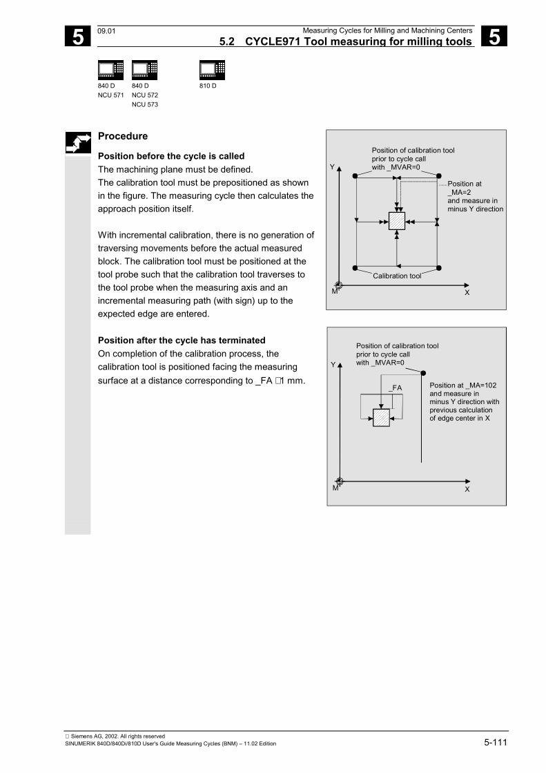
5 12.97 Measuring Cycles for Milling and Machining Centers 5.2 CYCLE971 Tool measuring for milling tools
5
840 DNCU 571
840 DNCU 572NCU 573
810 D
Siemens AG, 2002. All rights reservedSINUMERIK 840D/840Di/810D User's Guide Measuring Cycles (BNM) – 11.02 Edition 5-111
Procedure
Position before the cycle is called The machining plane must be defined. The calibration tool must be prepositioned as shownin the figure. The measuring cycle then calculates theapproach position itself. With incremental calibration, there is no generation oftraversing movements before the actual measuredblock. The calibration tool must be positioned at thetool probe such that the calibration tool traverses tothe tool probe when the measuring axis and anincremental measuring path (with sign) up to theexpected edge are entered. Position after the cycle has terminated On completion of the calibration process, thecalibration tool is positioned facing the measuringsurface at a distance corresponding to _FA ⋅ 1 mm.
Calibration tool
Position of calibration toolprior to cycle callwith _MVAR=0
Position at_MA=2 and measure inminus Y direction
Y
XM
Y
XM
_FA
Position of calibration toolprior to cycle callwith _MVAR=0
Position at _MA=102and measure in minus Y direction withprevious calculationof edge center in X
09.01
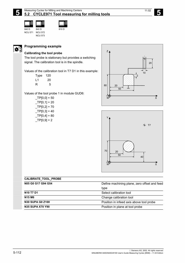
5 Measuring Cycles for Milling and Machining Centers 12.97 5.2 CYCLE971 Tool measuring for milling tools
5
840 DNCU 571
840 DNCU 572NCU 573
810 D
Siemens AG, 2002. All rights reserved5-112 SINUMERIK 840D/840Di/810D User's Guide Measuring Cycles (BNM) – 11.02 Edition
Programming example
Calibrating the tool probe The tool probe is stationary but provides a switchingsignal. The calibration tool is in the spindle. Values of the calibration tool in T7 D1 in this example: Type 120 L1 20 R 5 Values of the tool probe 1 in module GUD6: _TP[0,0] = 50 _TP[0,1] = 20 _TP[0,2] = 70 _TP[0,3] = 40
_TP[0,4] = 80 _TP[0,9] = 2
Z
80
20
M
10
5020
X
2
Y
5070 20
M
40
X
T7
CALIBRATE_TOOL_PROBE N05 G0 G17 G94 G54 Define machining plane, zero offset and feed
type N10 T7 D1 Select calibration tool N15 M6 Change calibration tool N30 SUPA G0 Z100 Position in infeed axis above tool probe N35 SUPA X70 Y90 Position in plane at tool probe
11.02
5 12.97 Measuring Cycles for Milling and Machining Centers 5.2 CYCLE971 Tool measuring for milling tools
5
840 DNCU 571
840 DNCU 572NCU 573
810 D
Siemens AG, 2002. All rights reservedSINUMERIK 840D/840Di/810D User's Guide Measuring Cycles (BNM) – 11.02 Edition 5-113
N40 _MVAR=0 _MA=102 _TZL=0.005 _TSA=5 _PRNUM=1_VMS=0 _FA=5 _NMSP=1
Parameters for calibrating in the Y axis withdetection of probe center in X. The data fieldof tool probe 1 is active.
N50 CYCLE971 Calibration in minus Y direction N55 SUPA Z100 Run up in infeed axis in rapid traverse N60 SUPA Y30
N65 _MA=2 In plane, traverse to position from whichcalibration is possible in plus Y direction
N70 CYCLE971 Calibrate in plus Y direction (probe centeredin X)
N80 SUPA X70 Z100 Retract from probe in rapid traverse in Xaxis and Z axis
N85 _MA=1 Calibration in the X axis N90 CYCLE971 Calibration in minus X direction N100 SUPA Y10 Z100 Retract from probe in rapid traverse in Y axis
and Z axis N110 SUPA X10 In X axis, traverse to position from which
calibration is possible in plus direction N120 CYCLE971 Calibration in plus X direction N130 SUPA Z100 Run up in infeed axis N140 _MA=3 Calibration in the Z axis N150 CYCLE971 Calibration in minus Z direction ... N160 M2 End of program
The new trigger values in -X, +X, -Y, +Y and -Z arestored in the global data of tool probe 1_TP[0,0...4] ifthey deviate by more than 0.005 mm from the oldvalues. Deviations of up to 5 mm are permissible.
11.02
5 Measuring Cycles for Milling and Machining Centers 12.97 5.2 CYCLE971 Tool measuring for milling tools
5
840 DNCU 571
840 DNCU 572NCU 573
810 D
Siemens AG, 2002. All rights reserved5-114 SINUMERIK 840D/840Di/810D User's Guide Measuring Cycles (BNM) – 11.02 Edition
5.2.3 CYCLE971 Measure tool
Function
The cycle calculates the new tool length or radius andchecks whether the difference from the old tool length orradius, possibly corrected by an empirical value, is withina defined tolerance range (upper limits: safe area _TSAand dimension difference check _TDIF, lower limit: zerooffset area _TZL).If this range is not violated, the new tool length or radiusis accepted, otherwise an alarm is output. Violation of thelower limit is not corrected. Measuring is possible either with• Motionless spindle• Rotating spindle
The entry in the current tool offset memory can beoptionally as absolute value in the tool offset data or asdifference in the wear data.
Precondition• The tool probe must be calibrated.• The tool geometry data must be entered in a tool
offset data record.• The tool must be active.• The desired machining plane must be activated.• The tool must be prepositioned in such a manner that
collision-free approach to the probe is possible in themeasuring cycle.
Special features of measurement with rotatingspindle• As standard the cycle-internal calculation of feed and
speed is executed from the limit values defined in thedata field _CM[] for peripheral speed, rotation speed,minimum feed, maximum feed and measuringaccuracy, as well as the intended direction of spindlerotation for measurement.Measuring is conducted by probing twice; the firstprobing action causes a higher feedrate. A maximumof three probing operations are possible formeasuring.
5 12.97 Measuring Cycles for Milling and Machining Centers 5.2 CYCLE971 Tool measuring for milling tools
5
840 DNCU 571
840 DNCU 572NCU 573
810 D
Siemens AG, 2002. All rights reservedSINUMERIK 840D/840Di/810D User's Guide Measuring Cycles (BNM) – 11.02 Edition 5-115
• The operator can deactivate the cycle-internal calculationvia the measuring cycle bit _CBIT[12] and specify his orher own values for feed and speed.
• The data field _MFS is for entering the values.• If the bit is set, the values from _MFS[0/1] are valid for the
first probing and the values from _MFS[2/3] for the second.If _MFS[2] = 0 only one probing action is performed. If_MFS[4] > 0 and _MFS[2] > 0, probing is performed inthree probing actions; the values from _MFS[4/5] are validin the third action.
• The monitoring operations from data field _CM[] are noteffective!
• If the spindle is motionless when the measuring cycle iscalled, the direction of rotation is determined from _CM[5].
Monitoring for measuring with rotating spindle and cycle-internal calculation_CM[0] Maximum permissible peripheral speed [m/min]/[feet/min]
Default: 60 m/min_CM[1] Maximum permissible speed for measuring with rotating spindle [rpm]
(if it is exceeded, the speed is automatically reduced)Default: 2000 rpm
_CM[2] Minimum feedrate for probing [mm/min]/[inch/min](prevents feeds from being too low with large tool radii)Default: 1mm/min
_CM[3] Required measuring accuracy [mm]/[inch]is effective with the last probing actionDefault: 0.005 mm
_CM[4] Maximum feedrate for probing [mm/min]/[inch/min]Default: 20 mm/min
_CM[5] Direction of spindle rotation during measuringDefault: 4 = M4
_CM[6] Feed factor 10: One probing action only with calculated feed≥1: 1st probing action with calculated feed ⋅ Feed factor 1Default: 10
_CM[7] Feed factor 20: 2nd probing operation with calculated feed (only valid with _CM[6]>0)≥1: 2nd probing action with calculated feed ⋅ Feed factor 2
3rd probing with calculated feedFeed factor 2 should be smaller than feed factor 1.Default: 0
NoticeIf the spindle is rotating when the measuring cycle is called,this direction of rotation remains independent of _CM[5]!
11.02
5 Measuring Cycles for Milling and Machining Centers 12.97 5.2 CYCLE971 Tool measuring for milling tools
5
840 DNCU 571
840 DNCU 572NCU 573
810 D
Siemens AG, 2002. All rights reserved5-116 SINUMERIK 840D/840Di/810D User's Guide Measuring Cycles (BNM) – 11.02 Edition
Parameters
_MVAR 1
2
Measure tool with motionless spindle(Length or radius)Measure tool with rotating spindle(Length or radius)
_MA123
103
203
Number of measuring axisMeasuring the radius in direction of the abscissaMeasuring the radius in direction of the ordinateMeasuring the length at center point of the toolprobeMeasuring the length, shifted around radius indirection of the abscissaMeasuring the length, shifted around radius indirection of the ordinate
_ID REAL ≥ 0 Parameter is usually set to 0.With multiple cutters the offset of tool length andthe highest point of the tool edge must be specifiedin _ID for radius measurement; the offset from thetool radius to the highest point of the tool edgemust be specified for length measurement.
_MFS[0] REAL Speed 1st probing (only with _CBIT[12]=1)_MFS[1] REAL Feed 1st probing_MFS[2] REAL Speed 2nd probing
0: Measurement terminated after 1st probing_MFS[3] REAL Feed 2nd probing_MFS[4] REAL Speed 3rd probing
0: Measurement terminated after 2nd probing_MFS[5] REAL Feed 3rd probing
These following additional parameters are also valid:_VMS, _CORA, _TZL, _TDIF, _TSA, _FA, _PRNUM,_EVNUM and _NMSP.See Sections 2.2 and 2.3.
Bit 3 in the channel-oriented bits in the measuringcycles is for determining whether the measured value isto be written absolute in length/radius parameters withsimultaneous deletion of the corresponding wear data(_CHBIT[3]=0) or the difference is to be written in thewear data (_CHBIT[3]=1).
11.02
5 12.97 Measuring Cycles for Milling and Machining Centers 5.2 CYCLE971 Tool measuring for milling tools
5
840 DNCU 571
840 DNCU 572NCU 573
810 D
Siemens AG, 2002. All rights reservedSINUMERIK 840D/840Di/810D User's Guide Measuring Cycles (BNM) – 11.02 Edition 5-117
Procedure
Position before the cycle is calledBefore the cycle is called a start position must beadopted from which it is possible to conduct a collision-free approach to the probe. The measuring cycle thencalculates the approach position itself.Position after the cycle has terminatedOn completion of the cycle, the tool nose is positionedfacing the measuring surface at a distancecorresponding to _FA.
5 Measuring Cycles for Milling and Machining Centers 12.97 5.2 CYCLE971 Tool measuring for milling tools
5
840 DNCU 571
840 DNCU 572NCU 573
810 D
Siemens AG, 2002. All rights reserved5-118 SINUMERIK 840D/840Di/810D User's Guide Measuring Cycles (BNM) – 11.02 Edition
Programming example
Measuring the length and the radius of a T3 drilling toolMEASURE_T3...N00 G17 G54 G94N05 T3 D1 Selection of the tool to be measuredN10 M6 Change toolN15 G0 SUPA Z100 Position in infeed axis above the tool probeN20 _CHBIT[3]=0 _CBIT[12]=0 Offset of tool geometry, cycle-internal
calculation of feed and speed for measuringwith rotating spindle
N30 _MVAR=1 _MA=3 _TZL=0.04 _TDIF=0.6 _TSA=1_PRNUM=1 _VMS=0 _NMSP=1 _FA=2 _EVNUM=0
Parameters for the cycle
N40 CYCLE971 Measure length with motionless spindleN50 SUPA X70 In X retracting from probeN70 _MA=1 _MVAR=2N80 CYCLE971 Measure radius in minus X direction with
rotating spindleN90 M2
The calculated length 1 and radius of the active tool areentered in the geometry memory of the active tool ifthey deviate by more than 0.04 mm or less than 0.6 mmfrom the old values.Values are corrected without empirical values.The wear memories of the active tool are cleared.
11.02
5 12.97 Measuring Cycles for Milling and Machining Centers5.3 CYCLE976 Calibrate workpiece probe 5
840 DNCU 571
840 DNCU 572NCU 573
FM-NC 810 D 840 Di
Siemens AG, 2002. All rights reservedSINUMERIK 840D/840Di/810D User's Guide Measuring Cycles (BNM) – 11.02 Edition 5-119
5.3 CYCLE976 Calibrate workpiece probe
Programming
CYCLE976
Function
With milling machines and machining centers, theprobe is usually loaded into the spindle from a toolmagazine.This may result in errors when further measurementsare taken on account of probe clamping tolerances inthe spindle.
Moreover, the triggering points in the axis directions thatnot only depend on the probe tip diameter but also onthe mechanical design of the probe and the velocity ofcontact between the probe and an obstacle must becalculated.
This is permitted by the calibration cycle which makes itpossible to calibrate the probe either in a hole (plane) oron a surface (applicate).
11.02
5 Measuring Cycles for Milling and Machining Centers 12.975.3 CYCLE976 Calibrate workpiece probe 5
840 DNCU 571
840 DNCU 572NCU 573
FM-NC 810 D 840 Di
Siemens AG, 2002. All rights reserved5-120 SINUMERIK 840D/840Di/810D User's Guide Measuring Cycles (BNM) – 11.02 Edition
Result parameters
The measuring cycle CYCLE976 supplies the followingvalues as results in the GUD5 module:
_OVR [4] REAL Actual value probe ball diameter_OVR [5] REAL Difference probe ball diameter_OVR [6]1) REAL Center point of the hole in the abscissa_OVR [7]1) REAL Center point of the hole in the ordinate_OVR [8] REAL Trigger point in minus direction, actual value, abscissa_OVR [10] REAL Trigger point in plus direction, actual value, abscissa_OVR [12] REAL Trigger point in minus direction, actual value, ordinate_OVR [14] REAL Trigger point in plus direction, actual value, ordinate_OVR [16] REAL Trigger point in minus direction, actual value, applicate_OVR [18] REAL Trigger point in plus direction, actual value, applicate_OVR [9] REAL Trigger point in minus direction, difference, abscissa_OVR [11] REAL Trigger point in plus direction, difference, abscissa_OVR [13] REAL Trigger point in minus direction, difference, ordinate_OVR [15] REAL Trigger point in plus direction, difference, ordinate_OVR [17] REAL Trigger point in minus direction, difference, applicate_OVR [19] REAL Trigger point in plus direction, difference, applicate_OVR [20] REAL Positional deviation abscissa_OVR [21] REAL Positional deviation ordinate_OVR [24] REAL Angle at which the trigger points were determined_OVR [27] REAL Zero offset area_OVR [28] REAL Safe area_OVI [2] INTEGER Measuring cycle number_OVI [5] INTEGER Measuring probe number_OVI [9] INTEGER Alarm number1) for calibration variant with unknown
drilling center point only
Applicable probe types
The measuring cycle operates with the following probetypes which are coded via parameter _PRNUM:
• Multidirectional probe• Monodirectional probe (bidirectional probe)
05.98
5 12.97 Measuring Cycles for Milling and Machining Centers5.3 CYCLE976 Calibrate workpiece probe 5
840 DNCU 571
840 DNCU 572NCU 573
FM-NC 810 D 840 Di
Siemens AG, 2002. All rights reservedSINUMERIK 840D/840Di/810D User's Guide Measuring Cycles (BNM) – 11.02 Edition 5-121
Measurement variants
The measuring cycle CYCLE976 permits the followingcalibration variants which are specified via parameter_MVAR. Possible parameter values lie between 0...112101 andare put together as follows:
• Calibrate in random hole (plane) Digit Meaning 6 5 4 3 2 1 0 Paraxial calibration (in the plane) 1 Calibration at any angle (in the plane) 0 No position calculation 1 With calculation of position 0 4 axis directions 1 1 axis direction (specify measuring axis and axis direction) 2 2 axis directions (indicate measuring axis) 0 No calculation of probe ball 1 Calculation of probe ball (for measurement in plane) 0 With any data in the plane 1 Hole (for measurement in the plane), center of the hole known 81) Hole (for measurement in the plane), center of the hole not known • Calibration on any surface (applicate) Digit Meaning 6 5 4 3 2 1 0 Calibration on random surface 1 0 0 0 0 Calibration on any surface in applicate with calculation of probe length 1) Measuring cycles SW 4.4. and higher
05.98
5 Measuring Cycles for Milling and Machining Centers 12.975.3 CYCLE976 Calibrate workpiece probe 5
840 DNCU 571
840 DNCU 572NCU 573
FM-NC 810 D 840 Di
Siemens AG, 2002. All rights reserved5-122 SINUMERIK 840D/840Di/810D User's Guide Measuring Cycles (BNM) – 11.02 Edition
5.3.1 CYCLE976 Calibrate workpiece probe in any hole (plane) withknown hole center
Function
This measuring cycle makes it possible to calibrate theprobe in the plane in a random hole, e.g. on theworkpiece. The calculated trigger points areautomatically loaded in module GUD6.DEF if thecalculated difference from the stored trigger points lieswithin the tolerance band between _TZL and _TSA. If_TSA is exceeded an error message is output. Calibration is either paraxial or at a random angle.
Precondition The probe must be called with tool length offset. Tooltype 1x0 or 710 (3D probe) for SW 4 and higher ispermitted. The center point of the hole and its diametermust be known!
Parameters
_MVAR See Section 5.3 "Measurementvariants"
Definition of calibration variant
_SETVAL REAL Calibration setpoint = diameter of hole _MA 1, 2 Measuring axis (depends on the measurement
variant) _MD 0 positive axis direction
1 negative axis direction Measuring direction (depends on the measurementvariant)
_PRNUM INT Measuring probe number _STA11) REAL Starting angle (calibration takes place at this angle) 1) Enter only for calibrating at an angle.
These following additional parameters are also valid: _VMS, _CORA, _TZL, _TSA, _FA and _NMSP. See Sections 2.2 and 2.3.
Notice! When calibration is performed for the first time thedefault setting in the data field of the probe is still "0".For that reason, _TSA> radius probe ball must beprogrammed to avoid alarm "Safe area violated".
08.99
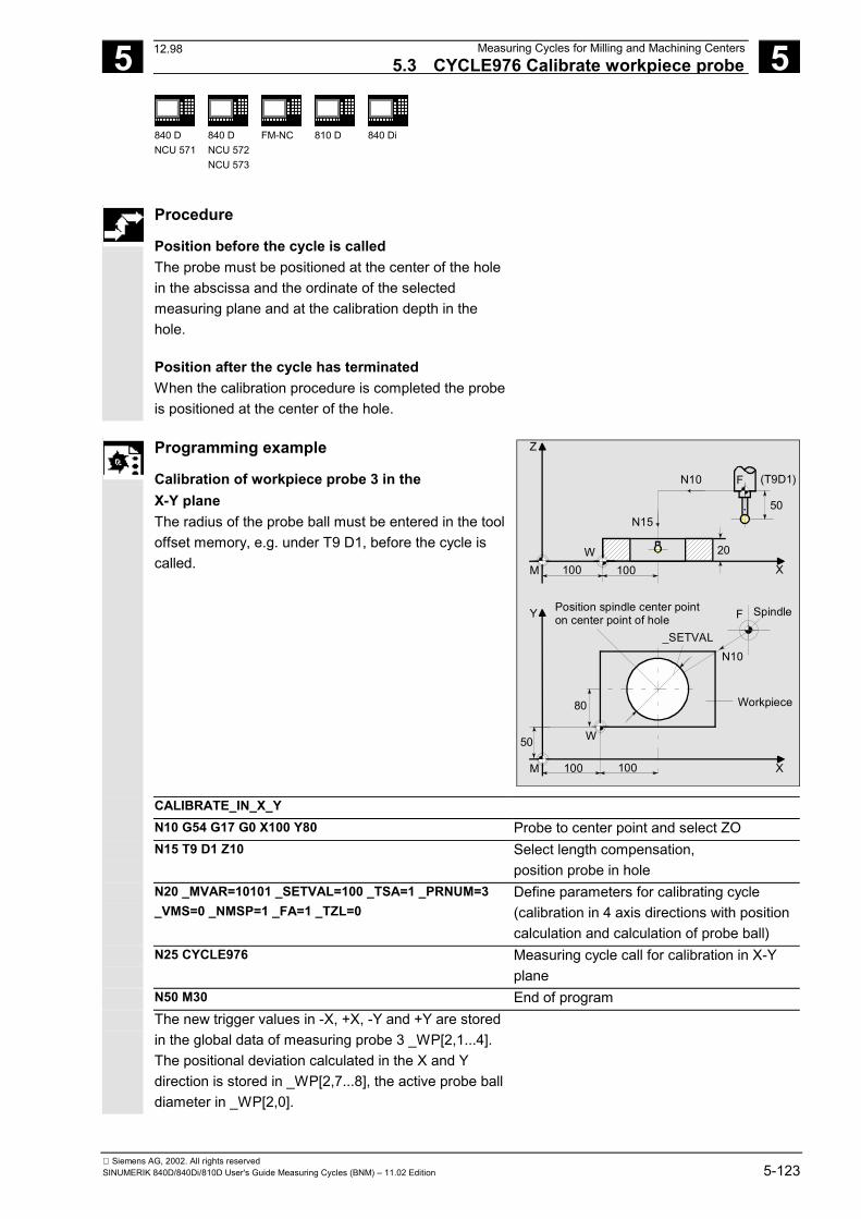
5 12.97 Measuring Cycles for Milling and Machining Centers5.3 CYCLE976 Calibrate workpiece probe 5
840 DNCU 571
840 DNCU 572NCU 573
FM-NC 810 D 840 Di
Siemens AG, 2002. All rights reservedSINUMERIK 840D/840Di/810D User's Guide Measuring Cycles (BNM) – 11.02 Edition 5-123
Procedure
Position before the cycle is called The probe must be positioned at the center of the holein the abscissa and the ordinate of the selectedmeasuring plane and at the calibration depth in thehole. Position after the cycle has terminated When the calibration procedure is completed the probeis positioned at the center of the hole.
Programming example
Calibration of workpiece probe 3 in theX-Y plane The radius of the probe ball must be entered in the tooloffset memory, e.g. under T9 D1, before the cycle iscalled.
Y
M
50
80
100 100
_SETVAL
SpindleF
Workpiece
N10
X
Position spindle center pointon center point of hole
W
50
(T9D1)N10 F
100 100
20
Z
M XW
N15
CALIBRATE_IN_X_Y N10 G54 G17 G0 X100 Y80 Probe to center point and select ZO N15 T9 D1 Z10 Select length compensation,
position probe in hole N20 _MVAR=10101 _SETVAL=100 _TSA=1 _PRNUM=3
_VMS=0 _NMSP=1 _FA=1 _TZL=0 Define parameters for calibrating cycle(calibration in 4 axis directions with positioncalculation and calculation of probe ball)
N25 CYCLE976 Measuring cycle call for calibration in X-Yplane
N50 M30 End of program The new trigger values in -X, +X, -Y and +Y are stored
in the global data of measuring probe 3 _WP[2,1...4].The positional deviation calculated in the X and Ydirection is stored in _WP[2,7...8], the active probe balldiameter in _WP[2,0].
12.98
5 Measuring Cycles for Milling and Machining Centers 12.975.3 CYCLE976 Calibrate workpiece probe 5
840 DNCU 571
840 DNCU 572NCU 573
FM-NC 810 D 840 Di
Siemens AG, 2002. All rights reserved5-124 SINUMERIK 840D/840Di/810D User's Guide Measuring Cycles (BNM) – 11.02 Edition
5.3.2 CYCLE976 Calibrate workpiece probe in any hole (plane) with unknown holecenter (measuring cycles SW 4.4 and higher)
Function
With this measuring cycle it is possible to calibrate the probe in anyhole whose precise center point is not known. With this measuring version, first the center and positional deviation(skew) is determined and then all the trigger points in all four axisdirections of the plane. The measuring cycle also places the derivedcenter point of the hole in OVR fields 6 and 7. Precondition• The probe must be called with tool length offset. Permissible tool
types:- 1x0 or in measuring cycle SW 4 and higher also 710 (3D probe- in measuring cycle SW 5.4 and higher � 500 or in measuring cycle SW 6.2 and higher � also 580 with tool cutting edge
positions 5 to 8 under the conditions stated in Section 5.1.• The exact diameter of the hole must be known.• The spindle must be SPOS capable.• Probe in spindle can be positioned 0...360 degrees (all-round
coverage).
Parameters
_MVAR 8...10108 Calibration in hole, center unknown _SETVAL REAL Calibration setpoint = diameter of hole _PRNUM INT Measuring probe number
These following additional parameters are also valid: _VMS, _CORA, _TZL, _TSA, _FA and _NMSP. See Sections 2.2 and 2.3.
Notice! When calibration is performed for the first time thedefault setting in the data field of the probe is still "0".For that reason, _TSA> radius probe ball must beprogrammed to avoid alarm "Safe area violated".
Procedure
Position before the cycle is called The probe must be positioned near the hole center inthe abscissa and the ordinate of the selected measuringplane and at the calibration depth in the hole.
09.01
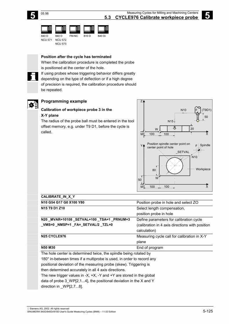
5 12.97 Measuring Cycles for Milling and Machining Centers5.3 CYCLE976 Calibrate workpiece probe 5
840 DNCU 571
840 DNCU 572NCU 573
FM-NC 810 D 840 Di
Siemens AG, 2002. All rights reservedSINUMERIK 840D/840Di/810D User's Guide Measuring Cycles (BNM) – 11.02 Edition 5-125
Position after the cycle has terminated When the calibration procedure is completed the probeis positioned at the center of the hole.
If using probes whose triggering behavior differs greatlydepending on the type of deflection or if a high degreeof precision is required, the calibration procedure shouldbe repeated.
Programming example
Calibration of workpiece probe 3 in theX-Y plane The radius of the probe ball must be entered in the tooloffset memory, e.g. under T9 D1, before the cycle iscalled.
Y
M
50
80
100 100
_SETVAL
SpindleF
Workpiece
N10
X
Position spindle center point oncenter point of hole
W
50
(T9D1)N10 F
100 100
20
Z
M XW
N15
CALIBRATE_IN_X_Y N10 G54 G17 G0 X100 Y80 Position probe in hole and select ZO N15 T9 D1 Z10 Select length compensation,
position probe in hole N20 _MVAR=10108 _SETVAL=100 _TSA=1 _PRNUM=3
_VMS=0 _NMSP=1 _FA=_SETVAL/2 _TZL=0 Define parameters for calibration cycle(calibration in 4 axis directions with positioncalculation)
N25 CYCLE976 Measuring cycle call for calibration in X-Yplane
N50 M30 End of program The hole center is determined twice, the spindle being rotated by
180° in-between times if a multiprobe is used, in order to record anypositional deviation of the measuring probe (skew). Triggering isthen determined accurately in all 4 axis directions.The new trigger values in -X, +X, -Y and +Y are stored in the globaldata of probe 3_WP[2,1...4], the positional deviation in the X and Ydirection in _WP[2,7...8].
05.98
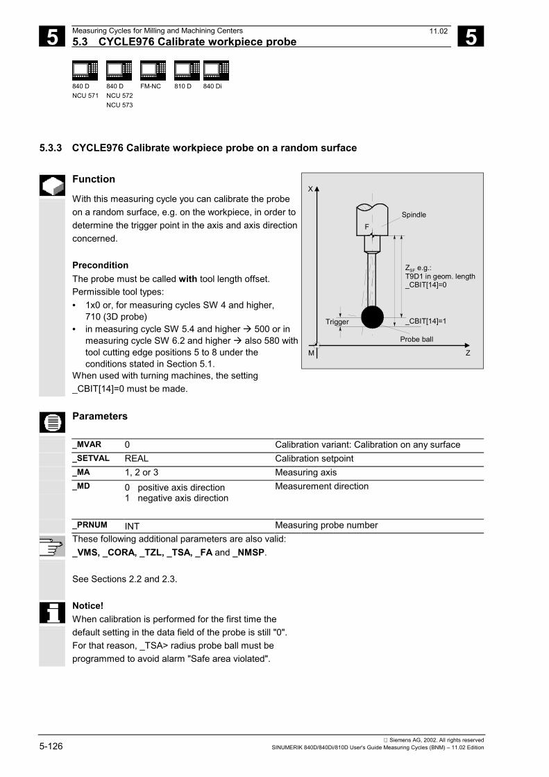
5 Measuring Cycles for Milling and Machining Centers 12.975.3 CYCLE976 Calibrate workpiece probe 5
840 DNCU 571
840 DNCU 572NCU 573
FM-NC 810 D 840 Di
Siemens AG, 2002. All rights reserved5-126 SINUMERIK 840D/840Di/810D User's Guide Measuring Cycles (BNM) – 11.02 Edition
5.3.3 CYCLE976 Calibrate workpiece probe on a random surface
Function
With this measuring cycle you can calibrate the probeon a random surface, e.g. on the workpiece, in order todetermine the trigger point in the axis and axis directionconcerned. PreconditionThe probe must be called with tool length offset.Permissible tool types:• 1x0 or, for measuring cycles SW 4 and higher,
710 (3D probe)• in measuring cycle SW 5.4 and higher � 500 or in
measuring cycle SW 6.2 and higher � also 580 withtool cutting edge positions 5 to 8 under theconditions stated in Section 5.1.
When used with turning machines, the setting_CBIT[14]=0 must be made.
SpindleF
X
M
Trigger
Probe ball
Z
ZSF e.g.:T9D1 in geom. length_CBIT[14]=0
_CBIT[14]=1
Parameters
_MVAR 0 Calibration variant: Calibration on any surface _SETVAL REAL Calibration setpoint _MA 1, 2 or 3 Measuring axis _MD 0 positive axis direction
1 negative axis direction
Measurement direction
_PRNUM INT Measuring probe number
These following additional parameters are also valid: _VMS, _CORA, _TZL, _TSA, _FA and _NMSP. See Sections 2.2 and 2.3.
Notice! When calibration is performed for the first time thedefault setting in the data field of the probe is still "0".For that reason, _TSA> radius probe ball must beprogrammed to avoid alarm "Safe area violated".
11.02
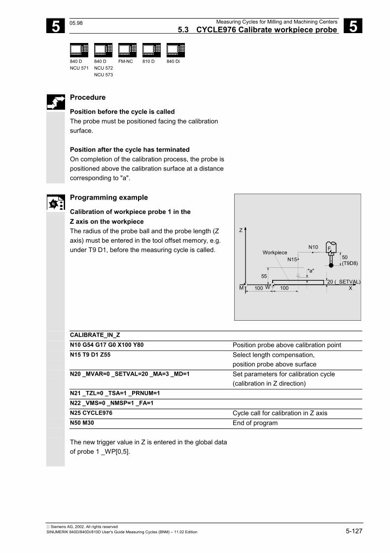
5 12.97 Measuring Cycles for Milling and Machining Centers5.3 CYCLE976 Calibrate workpiece probe 5
840 DNCU 571
840 DNCU 572NCU 573
FM-NC 810 D 840 Di
Siemens AG, 2002. All rights reservedSINUMERIK 840D/840Di/810D User's Guide Measuring Cycles (BNM) – 11.02 Edition 5-127
Procedure
Position before the cycle is called The probe must be positioned facing the calibrationsurface. Position after the cycle has terminated On completion of the calibration process, the probe ispositioned above the calibration surface at a distancecorresponding to "a".
Programming example
Calibration of workpiece probe 1 in theZ axis on the workpiece The radius of the probe ball and the probe length (Zaxis) must be entered in the tool offset memory, e.g.under T9 D1, before the measuring cycle is called.
Z
55
100 100
WorkpieceN10
XW
N15
20 (_SETVAL)
"a"
50 (T9D8)
M
F
CALIBRATE_IN_Z N10 G54 G17 G0 X100 Y80 Position probe above calibration point N15 T9 D1 Z55 Select length compensation,
position probe above surface N20 _MVAR=0 _SETVAL=20 _MA=3 _MD=1 Set parameters for calibration cycle
(calibration in Z direction) N21 _TZL=0 _TSA=1 _PRNUM=1 N22 _VMS=0 _NMSP=1 _FA=1 N25 CYCLE976 Cycle call for calibration in Z axis N50 M30 End of program
The new trigger value in Z is entered in the global dataof probe 1 _WP[0,5].
05.98
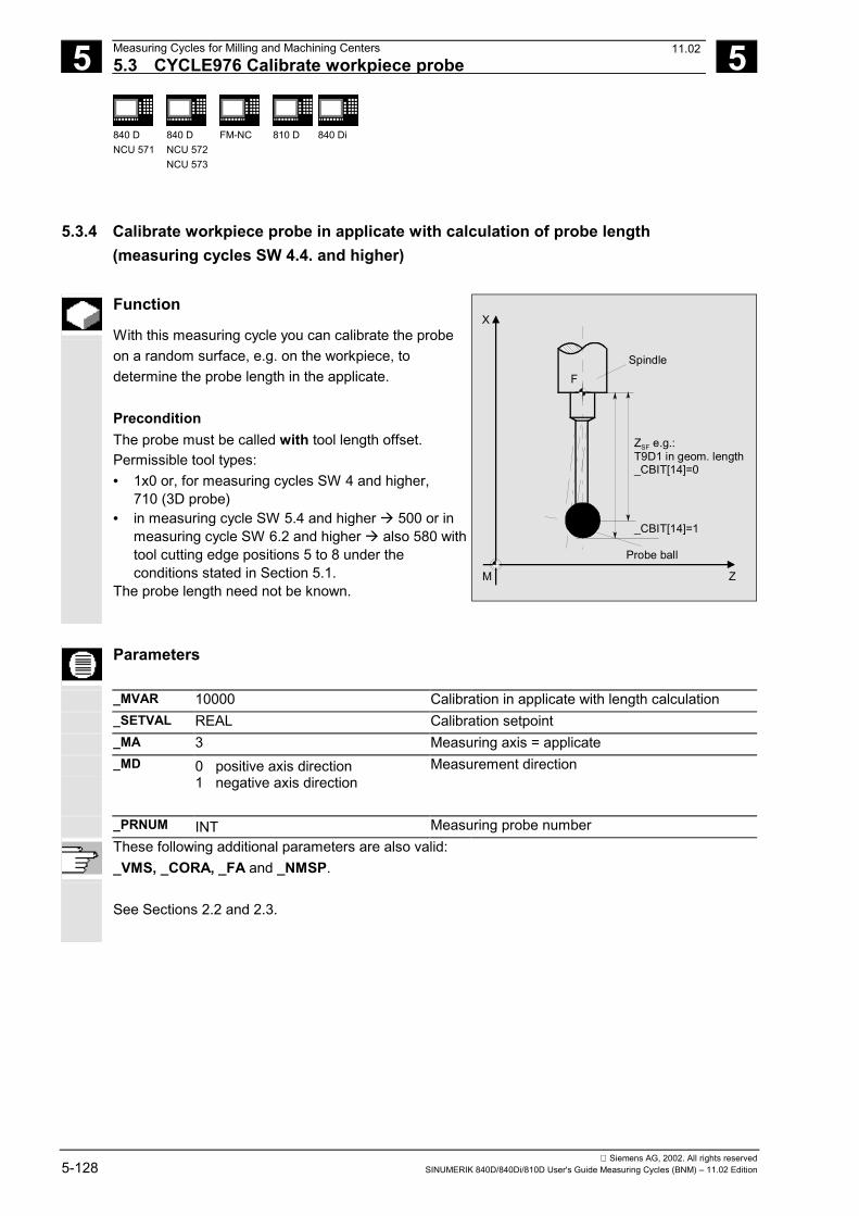
5 Measuring Cycles for Milling and Machining Centers 12.975.3 CYCLE976 Calibrate workpiece probe 5
840 DNCU 571
840 DNCU 572NCU 573
FM-NC 810 D 840 Di
Siemens AG, 2002. All rights reserved5-128 SINUMERIK 840D/840Di/810D User's Guide Measuring Cycles (BNM) – 11.02 Edition
5.3.4 Calibrate workpiece probe in applicate with calculation of probe length(measuring cycles SW 4.4. and higher)
Function
With this measuring cycle you can calibrate the probeon a random surface, e.g. on the workpiece, todetermine the probe length in the applicate. PreconditionThe probe must be called with tool length offset.Permissible tool types:• 1x0 or, for measuring cycles SW 4 and higher,
710 (3D probe)• in measuring cycle SW 5.4 and higher � 500 or in
measuring cycle SW 6.2 and higher � also 580 withtool cutting edge positions 5 to 8 under theconditions stated in Section 5.1.
The probe length need not be known.
SpindleF
X
M
Probe ball
Z
ZSF e.g.:T9D1 in geom. length_CBIT[14]=0
_CBIT[14]=1
Parameters
_MVAR 10000 Calibration in applicate with length calculation _SETVAL REAL Calibration setpoint _MA 3 Measuring axis = applicate _MD 0 positive axis direction
1 negative axis direction
Measurement direction
_PRNUM INT Measuring probe number
These following additional parameters are also valid: _VMS, _CORA, _FA and _NMSP. See Sections 2.2 and 2.3.
11.02
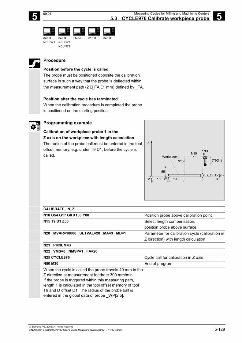
5 12.97 Measuring Cycles for Milling and Machining Centers5.3 CYCLE976 Calibrate workpiece probe 5
840 DNCU 571
840 DNCU 572NCU 573
FM-NC 810 D 840 Di
Siemens AG, 2002. All rights reservedSINUMERIK 840D/840Di/810D User's Guide Measuring Cycles (BNM) – 11.02 Edition 5-129
Procedure
Position before the cycle is called The probe must be positioned opposite the calibrationsurface in such a way that the probe is deflected withinthe measurement path (2 ⋅ _FA ⋅ 1 mm) defined by _FA. Position after the cycle has terminated When the calibration procedure is completed the probeis positioned on the starting position.
Programming example
Calibration of workpiece probe 1 in theZ axis on the workpiece with length calculation The radius of the probe ball must be entered in the tooloffset memory, e.g. under T9 D1, before the cycle iscalled.
Z
55
100 100
WorkpieceN10
XW
N15
20 (_SETVAL)
(T9D1)
M
F
CALIBRATE_IN_Z N10 G54 G17 G0 X100 Y80 Position probe above calibration point N15 T9 D1 Z55 Select length compensation,
position probe above surface N20 _MVAR=10000 _SETVAL=20 _MA=3 _MD=1 Parameter for calibration cycle (calibration in
Z direction) with length calculation N21 _PRNUM=3 N22 _VMS=0 _NMSP=1 _FA=20 N25 CYCLE976 Cycle call for calibration in Z axis N50 M30 End of program When the cycle is called the probe travels 40 mm in the
Z direction at measurement feedrate 300 mm/min.If the probe is triggered within this measuring path,length 1 is calculated in the tool offset memory of toolT9 and D offset D1. The radius of the probe ball isentered in the global data of probe _WP[2,5].
09.01
5 Measuring Cycles for Milling and Machining Centers 12.975.4 CYCLE977 Workpiece measurement: 5
840 DNCU 571
840 DNCU 572NCU 573
FM-NC 810 D 840 Di
Siemens AG, 2002. All rights reserved5-130 SINUMERIK 840D/840Di/810D User's Guide Measuring Cycles (BNM) – 11.02 Edition
5.4 CYCLE977 Workpiece measurement: Hole/shaft/groove/web/rectangle (paraxial)
Programming
CYCLE977
Function
This cycle determines the dimensions of holes, shafts,grooves or webs. It can either perform automatic tooloffset or zero offset to compensate for a difference fromthe derived center point of the hole, shaft, rectangle inthe axes of the plane, or correct a groove or web in themeasurement axis additively.
In SW 4.3 and higher the measuring cycle has beenexpanded to include the measurement variants• Measurement of a ring inside and outside• Measurement of a rectangle inside, outside
with/without protection zone. As of SW 4.5, it is also possible to measure the grooveand web in the protection zone.
Result parameters
Depending on the measurement variant, the measuringcycle CYCLE977 supplies the following values asresults in the GUD5 module (not for rectanglemeasurement):
_OVR [0] REAL Setpoint diameter/width hole, shaft, groove, web _OVR [1] REAL Setpoint center point/center hole, shaft, groove, web in abscissa _OVR [2] REAL Setpoint center point/center hole, shaft, groove, web in ordinate _OVR [4] REAL Actual value diameter/width hole, shaft, groove, web _OVR [5] REAL Actual value center point/center hole, shaft, groove, web in abscissa _OVR [6] REAL Actual value center point/center hole, shaft, groove, web in ordinate _OVR [8]1) REAL Upper tolerance limit for diameter/width hole, shaft, groove, web _OVR [12] 1) REAL Lower tolerance limit for diameter/width hole, shaft, groove, web _OVR [16] REAL Difference diameter/width hole, shaft, groove, web _OVR [17] REAL Difference center point/center hole, shaft, groove, web in abscissa _OVR [18] REAL Difference center point/center hole, shaft, groove, web in ordinate _OVR [20] 1) REAL Offset value _OVR [27] 1) REAL Zero offset area
10.00
5 12.97 Measuring Cycles for Milling and Machining Centers5.4 CYCLE977 Workpiece measurement: 5
840 DNCU 571
840 DNCU 572NCU 573
FM-NC 810 D 840 Di
Siemens AG, 2002. All rights reservedSINUMERIK 840D/840Di/810D User's Guide Measuring Cycles (BNM) – 11.02 Edition 5-131
_OVR [28] REAL Safe area _OVR [29] 1) REAL Dimensional difference _OVR [30] 1) REAL Empirical value _OVR [31] 1) REAL Mean value _OVI [0] INTEGER D number or ZO number _OVI [2] INTEGER Measuring cycle number _OVI [4] 1) INTEGER Weighting factor _OVI [5] INTEGER Measuring probe number _OVI [6] 1) INTEGER Mean value memory number _OVI [7] 1) INTEGER Empirical value memory number _OVI [8] INTEGER Tool number _OVI [9] INTEGER Alarm number
1) For workpiece measurement with tool offset only
Result parameters
Depending on the measurement variant rectanglemeasurement, CYCLE977 supplies the followingvalues as results in the GUD5 module:
_OVR [0] REAL Setpoint value rectangle length (in the abscissa) _OVR [1] REAL Setpoint value rectangle length (in the ordinate) _OVR [2] REAL Setpoint for rectangle center point, abscissa _OVR [3] REAL Setpoint for rectangle center point, ordinate _OVR [4] REAL Actual value for rectangle length (in the abscissa) _OVR [5] REAL Actual value for rectangle length (in the ordinate) _OVR [6] REAL Actual value for rectangle center point, abscissa _OVR [7] REAL Actual value for rectangle center point, ordinate _OVR [8] 1) REAL Upper tolerance limit for rectangle length (in the abscissa) _OVR [9] 1) REAL Upper tolerance limit for rectangle length (in the ordinate) _OVR [12] 1) REAL Lower tolerance limit for rectangle length (in the abscissa) _OVR [13] 1) REAL Lower tolerance limit for rectangle length (in the ordinate) _OVR [16] REAL Difference of rectangle length (in the abscissa) _OVR [17] REAL Difference of rectangle length (in the ordinate) _OVR [18] REAL Difference of rectangle center point, abscissa _OVR [19] REAL Difference of rectangle center point, ordinate _OVR [20] 1) REAL Offset value _OVR [27] 1) REAL Zero offset area _OVR [28] REAL Safe area _OVR [29] 1) REAL Dimensional difference _OVR [30] 1) REAL Empirical value _OVR [31] 1) REAL Mean value
10.00
5 Measuring Cycles for Milling and Machining Centers 12.975.4 CYCLE977 Workpiece measurement: 5
840 DNCU 571
840 DNCU 572NCU 573
FM-NC 810 D 840 Di
Siemens AG, 2002. All rights reserved5-132 SINUMERIK 840D/840Di/810D User's Guide Measuring Cycles (BNM) – 11.02 Edition
_OVI [0] INTEGER D number or ZO number _OVI [2] INTEGER Measuring cycle number _OVI [4] 1) INTEGER Weighting factor _OVI [5] INTEGER Measuring probe number _OVI [6] 1) INTEGER Mean value memory number _OVI [7] 1) INTEGER Empirical value memory number _OVI [8] INTEGER Tool number _OVI [9] INTEGER Alarm number _OVI [11] 2) INTEGER Status offset request
1) For workpiece measurement with tool offset only2) For measuring cycle SW 6.2 and higher; only for
zero offset
Applicable probe types
The measuring cycle operates with the following probetypes which are coded via parameter _PRNUM:• Multidirectional probe• Monodirectional probe (bidirectional probe)
Measurement variants and prepositioning
CYCLE977 permits the following measurement variantswhich are specified via parameter _MVAR.
Value Measurement variant Prepositioningin plane
Prepositioning in applicate
1 Measure hole with tool offset Hole center point At measuring depth 2 Measure shaft with tool offset Shaft center point Above shaft 3 Measure groove with tool offset Center point of groove At measuring depth 4 Measure web with tool offset Center point of web Above web 5 Measure rectangle inside Rectangle center point At measuring depth 6 Measure rectangle outside Rectangle center point Above rectangle 101 ZO calculation in hole
with ZO compensation Hole center point At measuring depth
102 ZO calculation on shaftwith ZO compensation
Shaft center point Above shaft
103 ZO calculation in groovewith ZO compensation
Center point of groove At measuring depth
104 ZO calculation on webwith ZO compensation
Center point of web Above web
11.02
5 12.97 Measuring Cycles for Milling and Machining Centers5.4 CYCLE977 Workpiece measurement: 5
840 DNCU 571
840 DNCU 572NCU 573
FM-NC 810 D 840 Di
Siemens AG, 2002. All rights reservedSINUMERIK 840D/840Di/810D User's Guide Measuring Cycles (BNM) – 11.02 Edition 5-133
105 ZO calculation in rectangle inside Rectangle center point At measuring depth 106 ZO calculation in rectangle outside Rectangle center point Above rectangle 1001 Measure hole with contouring of a
protection zone Hole center point Above hole
1002 Measure shaft by including for a protectionzone
Shaft center point Above shaft
10031)
Measure hole with contouring of aprotection zone
Center point of groove Above web
10041)
Measure web by including for a protectionzone
Web center point Above web
1005 Measure rectangle inside with protectionzone
Rectangle center point Above rectangle
1006 Measure rectangle outside with protectionzone
Rectangle center point Above rectangle
1101 ZO calculation of hole with contouring of aprotection zone
Hole center point Above hole
1102 ZO calculation of shaft by including aprotection zone
Shaft center point Above shaft
11031)
ZO calculation in groove with contouringof a protection zone
Groove center point Above web
11041)
ZO calculation at web by including aprotection zone
Web center point Above web
1105 ZO calculation in rectangle inside withprotection zone
Rectangle center point Above rectangle
1106 ZO calculation in rectangle outside withprotection zone
Rectangle center point Above rectangle
The measuring height in the applicate in whichmeasuring is then performed in the plane is derivedfrom the prepositioning in the applicate and theincremental parameter _ID. 1) Measuring cycles SW 4.5 and higher
08.99
5 Measuring Cycles for Milling and Machining Centers 12.97 5.4.1CYCLE977 Measure hole, shaft, groove, web, rectangle
5
840 DNCU 571
840 DNCU 572NCU 573
FM-NC
810 D
840 Di
Siemens AG, 2002. All rights reserved5-134 SINUMERIK 840D/840Di/810D User's Guide Measuring Cycles (BNM) – 11.02 Edition
5.4.1 CYCLE977 Measure hole, shaft, groove, web, rectangle
Function
Measure hole or shaft This measuring cycle gauges• within the hole or• on a shaft points P1, P2, P3 and P4 in the abscissa and ordinate.These four measured values are used to calculate theactual value and the position of the hole center point inthe abscissa and ordinate relative to the workpiece zero. The center point of the abscissa is calculated from pointsP1 and P2. The probe is then positioned at the centerpoint calculated and points P3 and P4 are measured.These two points are used to calculate the hole/shaftcenter point in the ordinate and the hole/shaft diameter.
In SW 4.3 and higher, travel around (hole) andconsideration (shaft) of a protection zone are supported.This provides for retraction for intermediate positioningin the applicate.
Measure groove or web This measuring cycle gauges• within the groove or• on two parallel surfaces (web) in the measuring axis. The two measured values are used to calculate theactual value of the groove/the actual distance betweenthe parallel surfaces, as well as the position of thegroove center point/the center point in the measuringaxis, relative to the workpiece zero. Measure rectangle inside or outside The measuring cycle automatically approaches 4measuring points and determines the rectangle centerpoint. Optionally, a rectangle-shaped protection zone relatingto the rectangle center point can be traveled around.
5 12.97 Measuring Cycles for Milling and Machining Centers 5.4.1CYCLE977 Measure hole, shaft, groove, web, rectangle
5
840 DNCU 571
840 DNCU 572NCU 573
FM-NC
810 D
840 Di
Siemens AG, 2002. All rights reservedSINUMERIK 840D/840Di/810D User's Guide Measuring Cycles (BNM) – 11.02 Edition 5-135
Options for hole and shaft diameter, groove orweb width• An empirical value stored in the GUD5 module is
subsequently taken into account with the correctsign.
• A mean value derivation over several parts ispossible as an option.
• Depending on the definition of _KNUM, no automaticoffset is performed or, alternatively, lengthcompensation or radius compensation (differencehalved) of a tool to be specified is carried out.
PreconditionThe probe must be called with tool length offset.Permissible tool types:• 1x0 or, for measuring cycles SW 4 and higher,
710 (3D probe)• on meas. cycle SW 5.4 � 500 or on meas. cycle
SW 6.2 � also 580 with tool cutting edge positions5 to 8 under the conditions stated in Section 5.1.
Parameters
_MVAR 123456
1001
1002
10031)
10041)
1005
1006
Measure hole with tool offsetMeasure shaft with tool offsetMeasure groove with tool offsetMeasure web with tool offsetMeasure rectangle inside with tool offsetMeasure rectangle outside with tool offsetMeasure hole by contouring a protection zone withtool offsetMeasure shaft by including a protection zone withtool offsetMeasure groove by contouring a protection zonewith tool offsetMeasure web by including a protection zone withtool offsetMeasure rectangle inside with protection zone withtool offsetMeasure rectangle outside with protection zonewith tool offset
_SETVAL REAL Setpoint (acc. to drawing)(only for hole/shaft/groove/web)
_SETV[0]_SETV[1]
REAL Setpoint value rectangle length (in the abscissa)Setpoint value rectangle length (in the ordinate)(only when measuring a rectangle)
1) Measuring cycles SW 4.5 and higher
11.02
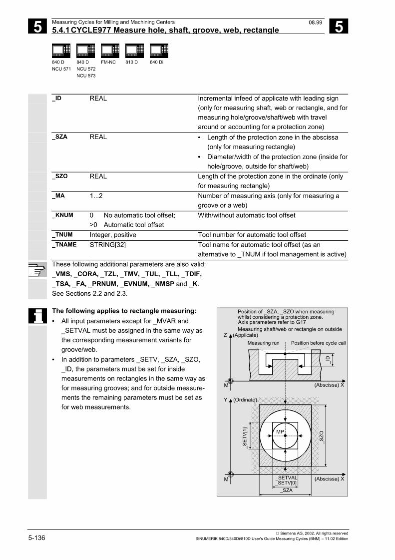
5 Measuring Cycles for Milling and Machining Centers 12.97 5.4.1CYCLE977 Measure hole, shaft, groove, web, rectangle
5
840 DNCU 571
840 DNCU 572NCU 573
FM-NC
810 D
840 Di
Siemens AG, 2002. All rights reserved5-136 SINUMERIK 840D/840Di/810D User's Guide Measuring Cycles (BNM) – 11.02 Edition
_ID REAL Incremental infeed of applicate with leading sign(only for measuring shaft, web or rectangle, and formeasuring hole/groove/shaft/web with travelaround or accounting for a protection zone)
_SZA REAL • Length of the protection zone in the abscissa(only for measuring rectangle)
• Diameter/width of the protection zone (inside forhole/groove, outside for shaft/web)
_SZO REAL Length of the protection zone in the ordinate (onlyfor measuring rectangle)
_MA 1...2 Number of measuring axis (only for measuring agroove or a web)
_KNUM 0 No automatic tool offset;>0 Automatic tool offset
With/without automatic tool offset
_TNUM Integer, positive Tool number for automatic tool offset _TNAME STRING[32] Tool name for automatic tool offset (as an
alternative to _TNUM if tool management is active)
These following additional parameters are also valid: _VMS, _CORA, _TZL, _TMV, _TUL, _TLL, _TDIF,_TSA, _FA, _PRNUM, _EVNUM, _NMSP and _K. See Sections 2.2 and 2.3.
The following applies to rectangle measuring:• All input parameters except for _MVAR and
_SETVAL must be assigned in the same way asthe corresponding measurement variants forgroove/web.
• In addition to parameters _SETV, _SZA, _SZO,_ID, the parameters must be set for insidemeasurements on rectangles in the same way asfor measuring grooves; and for outside measure-ments the remaining parameters must be set asfor web measurements.
Z (Applicate)
(Abscissa) XM
Y (Ordinate)
M (Abscissa) X_SETV[0]
_SZO
_SZA
_SET
V[1] MP
Measuring run Position before cycle call
_ID
_SETVAL
Measuring shaft/web or rectangle on outside
Position of _SZA, _SZO when measuringwhilst considering a protection zone.Axis parameters refer to G17
08.99
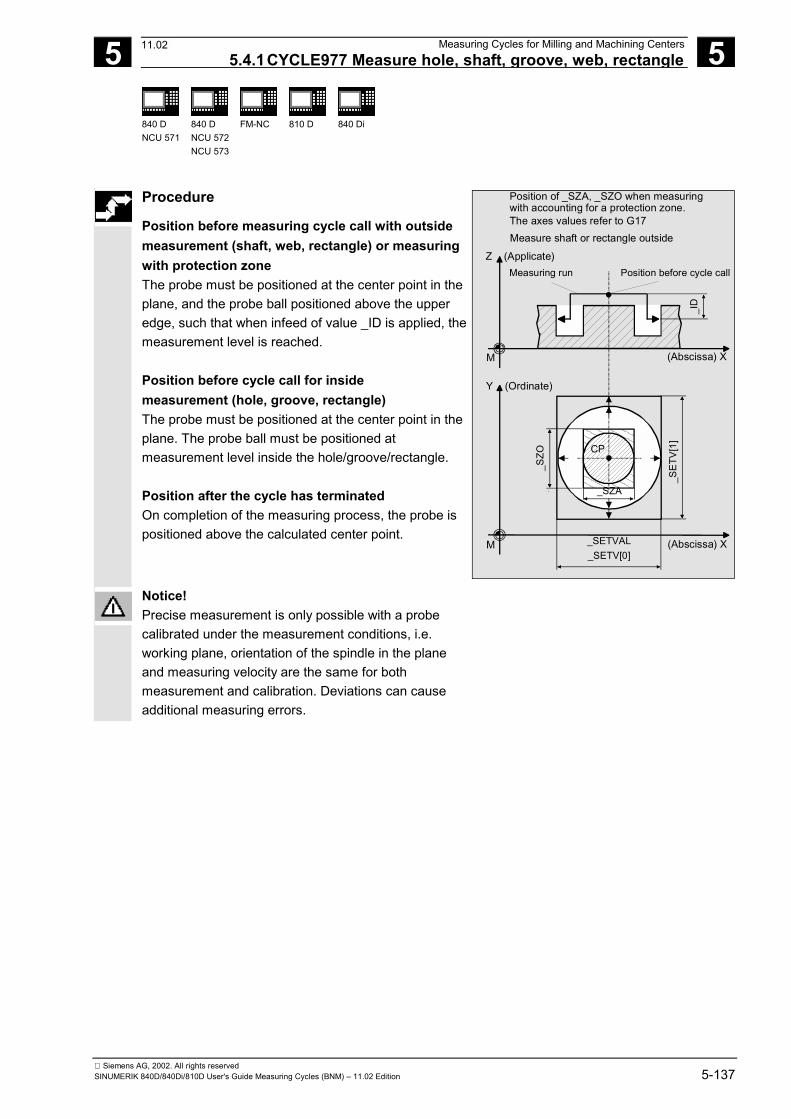
5 12.97 Measuring Cycles for Milling and Machining Centers 5.4.1CYCLE977 Measure hole, shaft, groove, web, rectangle
5
840 DNCU 571
840 DNCU 572NCU 573
FM-NC
810 D
840 Di
Siemens AG, 2002. All rights reservedSINUMERIK 840D/840Di/810D User's Guide Measuring Cycles (BNM) – 11.02 Edition 5-137
Procedure
Position before measuring cycle call with outsidemeasurement (shaft, web, rectangle) or measuringwith protection zone The probe must be positioned at the center point in theplane, and the probe ball positioned above the upperedge, such that when infeed of value _ID is applied, themeasurement level is reached. Position before cycle call for insidemeasurement (hole, groove, rectangle) The probe must be positioned at the center point in theplane. The probe ball must be positioned atmeasurement level inside the hole/groove/rectangle. Position after the cycle has terminated On completion of the measuring process, the probe ispositioned above the calculated center point.
Z (Applicate)
(Abscissa) XM
Y (Ordinate)
_SETVALM (Abscissa) X_SETV[0]
_SET
V[1]
_SZA
_SZO CP
Measuring run Position before cycle call
_ID
Measure shaft or rectangle outside
Position of _SZA, _SZO when measuringwith accounting for a protection zone.The axes values refer to G17
Notice!Precise measurement is only possible with a probecalibrated under the measurement conditions, i.e.working plane, orientation of the spindle in the planeand measuring velocity are the same for bothmeasurement and calibration. Deviations can causeadditional measuring errors.
11.02
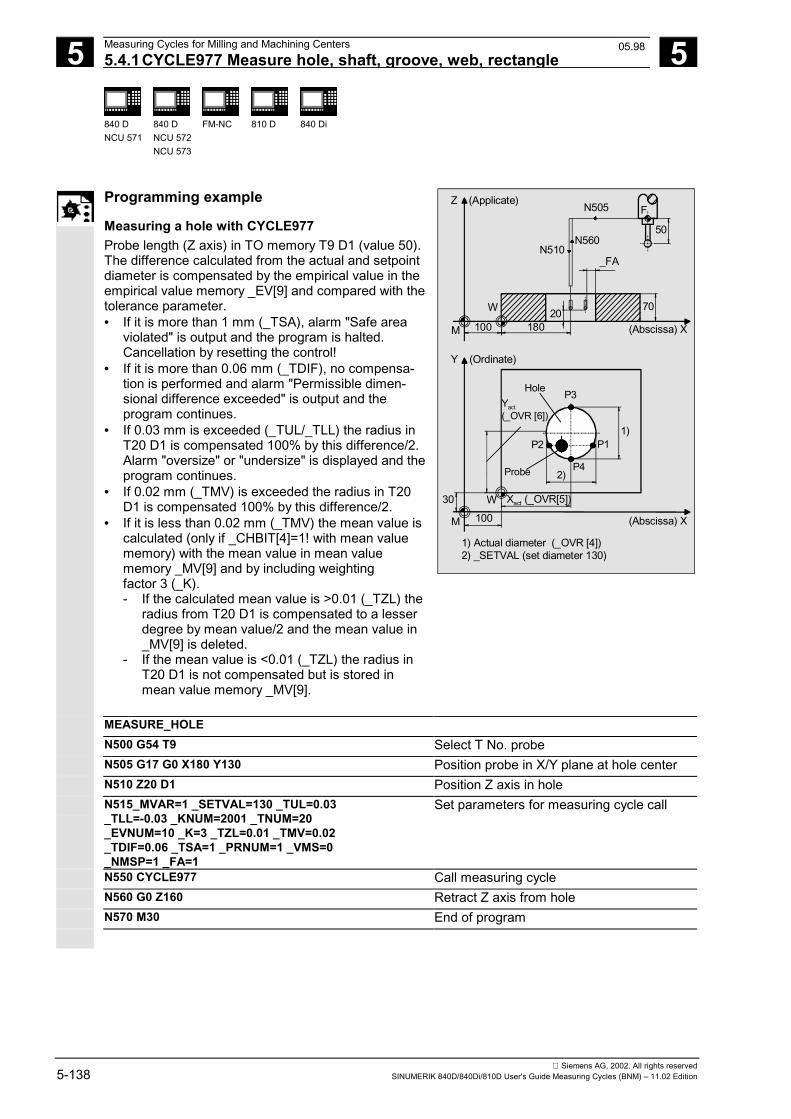
5 Measuring Cycles for Milling and Machining Centers 12.97 5.4.1CYCLE977 Measure hole, shaft, groove, web, rectangle
5
840 DNCU 571
840 DNCU 572NCU 573
FM-NC
810 D
840 Di
Siemens AG, 2002. All rights reserved5-138 SINUMERIK 840D/840Di/810D User's Guide Measuring Cycles (BNM) – 11.02 Edition
Programming example
Measuring a hole with CYCLE977 Probe length (Z axis) in TO memory T9 D1 (value 50). The difference calculated from the actual and setpointdiameter is compensated by the empirical value in theempirical value memory _EV[9] and compared with thetolerance parameter.• If it is more than 1 mm (_TSA), alarm "Safe area
violated" is output and the program is halted.Cancellation by resetting the control!
• If it is more than 0.06 mm (_TDIF), no compensa-tion is performed and alarm "Permissible dimen-sional difference exceeded" is output and theprogram continues.
• If 0.03 mm is exceeded (_TUL/_TLL) the radius inT20 D1 is compensated 100% by this difference/2.Alarm "oversize" or "undersize" is displayed and theprogram continues.
• If 0.02 mm (_TMV) is exceeded the radius in T20D1 is compensated 100% by this difference/2.
• If it is less than 0.02 mm (_TMV) the mean value iscalculated (only if _CHBIT[4]=1! with mean valuememory) with the mean value in mean valuememory _MV[9] and by including weightingfactor 3 (_K).- If the calculated mean value is >0.01 (_TZL) the radius from T20 D1 is compensated to a lesser degree by mean value/2 and the mean value in _MV[9] is deleted.- If the mean value is <0.01 (_TZL) the radius in T20 D1 is not compensated but is stored in mean value memory _MV[9].
N505
N510N560
_FA
50
FZ (Applicate)
(Abscissa) X
7020W
M 100 180
1) Actual diameter (_OVR [4])2) _SETVAL (set diameter 130)
Y (Ordinate)
Probe
30
M
W Xact (_OVR[5])
(Abscissa) X
Yact(_OVR [6])
100
Hole P3
P1P2
P4
1)
2)
MEASURE_HOLE N500 G54 T9 Select T No. probe N505 G17 G0 X180 Y130 Position probe in X/Y plane at hole center N510 Z20 D1 Position Z axis in hole N515_MVAR=1 _SETVAL=130 _TUL=0.03
_TLL=-0.03 _KNUM=2001 _TNUM=20_EVNUM=10 _K=3 _TZL=0.01 _TMV=0.02 _TDIF=0.06 _TSA=1 _PRNUM=1 _VMS=0_NMSP=1 _FA=1
Set parameters for measuring cycle call
N550 CYCLE977 Call measuring cycle N560 G0 Z160 Retract Z axis from hole N570 M30 End of program
05.98
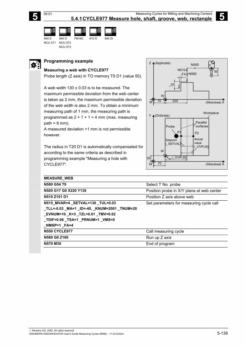
5 12.97 Measuring Cycles for Milling and Machining Centers 5.4.1CYCLE977 Measure hole, shaft, groove, web, rectangle
5
840 DNCU 571
840 DNCU 572NCU 573
FM-NC
810 D
840 Di
Siemens AG, 2002. All rights reservedSINUMERIK 840D/840Di/810D User's Guide Measuring Cycles (BNM) – 11.02 Edition 5-139
Programming example
Measuring a web with CYCLE977 Probe length (Z axis) in TO memory T9 D1 (value 50). A web width 130 ± 0.03 is to be measured. Themaximum permissible deviation from the web centeris taken as 2 mm, the maximum permissible deviationof the web width is also 2 mm. To obtain a minimummeasuring path of 1 mm, the measuring path isprogrammed as 2 + 1 + 1 = 4 mm (max. measuringpath = 8 mm).A measured deviation >1 mm is not permissiblehowever. The radius in T20 D1 is automatically compensated foraccording to the same criteria as described inprogramming example "Measuring a hole withCYCLE977".
Y (Ordinate)Workpiece
ProbeParallelsurfaces
P1 P2
W
Setpoint(_SETVAL)
Actualvalue(_OVR [4])
Xact (_OVR [5])5070M (Abscissa) X
Z (Applicate) N505 F
50N510N560_FA
_ID
M
W70 220 (Abscissa) X
MEASURE_WEB N500 G54 T9 Select T No. probe N505 G17 G0 X220 Y130 Position probe in X/Y plane at web center N510 Z101 D1 Position Z axis above web N515_MVAR=4 _SETVAL=130 _TUL=0.03
_TLL=-0.03 _MA=1 _ID=-40, _KNUM=2001 _TNUM=20_EVNUM=10 _K=3 _TZL=0.01 _TMV=0.02 _TDIF=0.06 _TSA=1 _PRNUM=1 _VMS=0_NMSP=1 _FA=4
Set parameters for measuring cycle call
N550 CYCLE977 Call measuring cycle N560 G0 Z160 Run up Z axis N570 M30 End of program
09.01
5 Measuring Cycles for Milling and Machining Centers 12.97 5.4.2CYCLE977 ZO calculation in hole, shaft, groove, web, rectangle
5
840 DNCU 571
840 DNCU 572NCU 573
FM-NC
810 D
840 Di
Siemens AG, 2002. All rights reserved5-140 SINUMERIK 840D/840Di/810D User's Guide Measuring Cycles (BNM) – 11.02 Edition
5.4.2 CYCLE977 ZO calculation in hole, shaft, groove, web, rectangle
Function
ZO calculation in a hole or on a shaft The measuring cycle gauges points P1, P2, P3 and P4• within the hole or• on the shaft points P1, P2, P3 and P4 in the abscissa and ordinate.These four measured values are used to calculate theposition of the hole/shaft center point in the abscissaand ordinate relative to the workpiece zero. The center point of the abscissa is calculated frompoints P1 and P2. The probe is then positioned at thecenter point calculated and points P3 and P4 aremeasured. These two points provide the hole/shaftcenter point of the ordinate.
In SW 4.3 and higher, travel around (hole) andconsideration (shaft) of a protection zone are supported.This provides for retraction for intermediate positioningin the applicate.
ZO calculation in a groove or on a web This measuring cycle gauges• within the groove or• on two parallel surfaces (web) in the measuring axis. These two measured values areused to calculate the position of the groove center point- or the center point on a web - in the measuring axis inrelation to the workpiece zero. ZO calculation in rectangle inside or outside The measuring cycle automatically approaches 4measuring points and determines the rectangle centerpoint. Optionally, a rectangle-shaped protection zone relatingto the rectangle center point can be traveled around.
05.98
5 12.97 Measuring Cycles for Milling and Machining Centers 5.4.2CYCLE977 ZO calculation in hole, shaft, groove, web, rectangle
5
840 DNCU 571
840 DNCU 572NCU 573
FM-NC
810 D
840 Di
Siemens AG, 2002. All rights reservedSINUMERIK 840D/840Di/810D User's Guide Measuring Cycles (BNM) – 11.02 Edition 5-141
The following applies to all ZO calculations: The difference is determined from the set center point(starting position) and the center point actual valuedetermined by the cycle. The multiplying factor for measurement path 1 mmmakes it possible to take into account the scatter bandof the blanks (set value). Depending on the definition of _KNUM, either noautomatic ZO entry is made, or the difference in themeasuring axis when measuring a groove or web, or inthe abscissa and ordinate, is added to the specified ZOmemory. If a fine offset is active (MD 18600:MM_FRAME_FINE_TRANS), an additive ZO will beimplemented in it, otherwise it is implemented in thecoarse offset. PreconditionThe probe must be called with tool length offset.Permissible tool types:• 1x0 or, for measuring cycles SW 4 and higher, 710
(3D probe)• on meas. cycle SW 5.4 � 500 or on meas. cycle
SW 6.2 � also 580 with tool cutting edge positions5 to 8 under the conditions stated in Section 5.1.
Parameters
_MVAR 101 102 103 104 105 106 1101 1102 11031)
11041)
1105 1106
ZO calculation in a hole with compensation of ZOZO calculation on a shaft with compensation of ZOZO calculation in a groove with compensation of ZOZO calculation on a web with compensation of ZO ZO calculation in rectangle inside with comp. of the ZO ZO calculation in rectangle outside with comp. of the ZO ZO calculation in hole by circumnavigating a protectionzone with compensation of the ZO ZO calculation of shaft by including a protection zonewith compensation of the ZO ZO calculation in groove by circumnavigating aprotection zone with compensation of the ZO ZO calculation of web by including a protection zonewith compensation of the ZO ZO calculation in rectangle inside with protection zonewith compensation of the ZO ZO calculation in rectangle outside with protection zonewith compensation of the ZO
1) Measuring cycles SW 4.5. and higher
11.02
5 Measuring Cycles for Milling and Machining Centers 12.97 5.4.2CYCLE977 ZO calculation in hole, shaft, groove, web, rectangle
5
840 DNCU 571
840 DNCU 572NCU 573
FM-NC
810 D
840 Di
Siemens AG, 2002. All rights reserved5-142 SINUMERIK 840D/840Di/810D User's Guide Measuring Cycles (BNM) – 11.02 Edition
_ID REAL Incremental infeed of applicate with leading sign(only for ZO calculation on a shaft with/withoutconsideration of a protection zone or on a web)
_MA 1...2 Number of measuring axis(only for ZO calculation in a groove or on a web)
_SETVAL REAL Setpoint value for diameter/width hole(only for hole, shaft, groove, web)
_SETV[0] _SETV[1]
REAL Setpoint value rectangle length (in the abscissa) Setpoint value rectangle length (in the ordinate) (only for ZO calculation for a rectangle)
_SZA REAL • Length of the protection zone in the abscissa(only for ZO calculation on rectangle)
• Diameter/width of the protection zone(inside for hole/groove, outside for shaft/web)
_SZO REAL Length of the protection zone in the ordinate(only for ZO calculation on rectangle)
_KNUM 0 no automaticZO compensation;
1...99 automatic additiveZO compensation in G54...G57, G505...G599
With/without automatic ZO calculation
Meas. cyclesSW 4.4 andhigher
1000 automatic additive ZO compensation in channel-specific basic frame1)
Meas. cyclesSW 6.2 andhigher2)
1011...1026 automatic ZO compensation in 1st to 16th basic frame (channel) ($P_CHBFR[0]...$P_CHBFR[15])
1051...1066 automatic ZO compensation in 1st to 16th basic frame (global) ($P_NCBFR[0]...$P_NCBFR[15])
2000 automatic ZO compensation in system framescratching system frame ($P_SETFR)
9999 automatic ZO compensation in an active frame settable frames G54..G57, G505...G599 or
for G500 in last active basic frame according to $P_CHBFRMASK (most significant bit)
1) As of measuring cycles SW 5.3, compensation iscarried out in the last basic frame (per MD 28081:MM_NUM_BASE_FRAMES) if more than one isavailable. If measuring cycles higher than SW 5.3are used at a control with SW 4, parameter _SI[1]in the GUD 6 module must be set to 4!
2) Measuring cycles version SW 6.2 and highercan only be used with NCK-SW 6.3 and higher.
These following additional parameters are also valid: _VMS, _CORA, _TSA, _FA, _PRNUM and _NMSP. See Sections 2.2 and 2.3.
11.02
5 12.97 Measuring Cycles for Milling and Machining Centers 5.4.2CYCLE977 ZO calculation in hole, shaft, groove, web, rectangle
5
840 DNCU 571
840 DNCU 572NCU 573
FM-NC
810 D
840 Di
Siemens AG, 2002. All rights reservedSINUMERIK 840D/840Di/810D User's Guide Measuring Cycles (BNM) – 11.02 Edition 5-143
The following applies to rectangle measuring:• All input parameters except for _MVAR and _SETVAL
must be assigned in the same way as thecorresponding measurement variants for groove/web.
• In addition to parameters _SETV, _SZA, _SZO, _ID,the parameters must be set for inside measurementson rectangles in the same way as for measuringgrooves; and for outside measurements the remainingparameters must be set as for web measurements.
Procedure
Position before measuring cycle call with outsidemeasurement (shaft, web, rectangle) or measuringwith protection zone The probe must be positioned at the center point in theplane, and the probe ball positioned above the upperedge, such that when infeed of value _ID is applied, themeasurement level is reached. Position before cycle call for insidemeasurement (hole, groove, rectangle) The probe must be positioned at the center point in theplane. The probe ball must be positioned atmeasurement level inside the hole/groove/rectangle. Position after the cycle has terminated When measuring is completed the probe is positionedon the calculated center point for inside and outsidemeasurement.
Notice!Precise measurement is only possible with a probecalibrated under the measurement conditions, i.e.working plane, orientation of the spindle in the planeand measuring velocity are the same for bothmeasurement and calibration. Deviations can causeadditional measuring errors.
5 Measuring Cycles for Milling and Machining Centers 12.97 5.4.2CYCLE977 ZO calculation in hole, shaft, groove, web, rectangle
5
840 DNCU 571
840 DNCU 572NCU 573
FM-NC
810 D
840 Di
Siemens AG, 2002. All rights reserved5-144 SINUMERIK 840D/840Di/810D User's Guide Measuring Cycles (BNM) – 11.02 Edition
Programming example
ZO calculation at a shaft with CYCLE977 Probe length (Z axis) in TO memory T9 D1 (value 50). A shaft is measured, the aim being that the hole centermeasured is identical to the setpoint positionapproached. The permissible deviation from the shaftcenter is taken as 2 mm; the deviation of the shaftdiameter from the setpoint diameter 130 may notexceed 6 mm. To obtain a minimum measuring path of1 mm up to the edge, the measuring path isprogrammed as 2 + 3 + 1 = 6 mm (max. measuringpath = 12 mm). Automatic compensation is performed in G54, X and Yby the calculated difference between the actual valueand set position of the shaft center, should it be lessthan 2 mm (_TSA) in both axes. Otherwise alarm "Safearea violated" is output and program execution cannotbe continued.
1) Shaft diameter (_SETVAL)2) Yact (_OVR [6])
Z (Applicate) N505
N510 N560F
50_FA
_ID101 100
W
M 100 180 (Abscissa) X
Y (Ordinate)
ShaftP4
1)P2
P1Probe
Set center point ∆Y (_OVR [18])
∆X (_OVR [17])
W
30
M 100 (Abscissa) X
Xact (_OVR [5])
P32)
ZO_SHAFT N500 G54 T9 Select T No. probe N505 Z101 D1 Position Z axis above shaft N510 G17 G0 X150 Y130 Position probe in X/Y plane at shaft center
point (setpoint position) N515_MVAR=102 _SETVAL=130 _ID=-30 _KNUM=1
_TSA=2 _PRNUM=1 _VMS=0 _NMSP=1 _FA=6 Set parameters for measuring cycle call
N550 CYCLE977 Call measuring cycle N555 G54 Renewed call of the zero offset G45 so that
the changes take effect through themeasuring cycle!
N560 G0 Z160 Run up Z axis N570 M30 End of program
08.99
5 12.97 Measuring Cycles for Milling and Machining Centers 5.4.2CYCLE977 ZO calculation in hole, shaft, groove, web, rectangle
5
840 DNCU 571
840 DNCU 572NCU 573
FM-NC
810 D
840 Di
Siemens AG, 2002. All rights reservedSINUMERIK 840D/840Di/810D User's Guide Measuring Cycles (BNM) – 11.02 Edition 5-145
Programming example
ZO calculation in a groove with CYCLE977 Probe length (Z axis) in TO memory T9 D1 (value 50). A groove in the X axis is measured, the aim being todetermine a groove center in X that is equal to thesetpoint position. The maximum permissible deviationof the groove center is taken as 2 mm. The groovewidth may deviate up to 6 mm from setpoint width100. To obtain a minimum measuring path of 1 mmup to the edge, the measuring path is programmed as2 + 3 + 1 = 6 mm (max. measurement path 12 mm). Automatic compensation in X (abscissa) in G54 isperformed in case the difference between the actualand setpoint position of the center of the groove in X isless than 2 mm (_TSA). Otherwise alarm "Safe areaviolated" is output and program execution cannot becontinued.
Y (Ordinate) WorkpieceGroove
P1P2
1) Yact (_OVR [6])
W
50
M 70 (Abscissa) X
Z (Applicate)N505
50
N510N560
F
50 130
W 40
_FA
70
(Abscissa) XM
Probe
Groove width(_SETVAL)
Act. value(_OVR [4])
1)
∆X (_OVR [17])
ZO_SHAFT N500 G54 T9 Select T No. probe N505 G17 G0 X150 Y130 Position probe in X/Y plane at groove center
(setpoint position) N510 Z40 D1 Position Z axis in groove N515_MVAR=103 _SETVAL=100 _MA=1 _KNUM=1
_TSA=2 _PRNUM=1 _VMS=0 _NMSP=1 _FA=6 Set parameters for measuring cycle call,measuring axis is X (abscissa)
N550 CYCLE977 Call measuring cycle N555 G54 Renewed call of the zero offset G45 so that
the changes take effect through themeasuring cycle!
N560 G0 Z160 Retract Z axis from groove N570 M30 End of program
08.99
5 Measuring Cycles for Milling and Machining Centers 12.97 5.5 CYCLE978 Workpiece measurement: Surface
5
840 DNCU 571
840 DNCU 572NCU 573
FM-NC
810 D
840 Di
Siemens AG, 2002. All rights reserved5-146 SINUMERIK 840D/840Di/810D User's Guide Measuring Cycles (BNM) – 11.02 Edition
5.5 CYCLE978 Workpiece measurement: Surface
Programming
CYCLE978
Function
The measuring cycle determines the dimensions ofsurfaces paraxially with reference to the workpiece zeroby single-point measurement and executes anautomatic tool compensation or zero offset in themeasuring axis. Differential measurements are also possible with thiscycle.
Result parameters
Depending on the measurement variant, CYCLE978makes the following values available as results in theGUD5 module:
_OVR [0] REAL Setpoint for measuring axis _OVR [1] REAL Setpoint for abscissa _OVR [2] REAL Setpoint for ordinate _OVR [3] REAL Setpoint for applicate _OVR [4] REAL Actual value for measuring axis _OVR [8] 1) REAL Upper tolerance limit for measuring axis _OVR [12] 1) REAL Lower tolerance limit for measuring axis _OVR [16] REAL Difference for measuring axis _OVR [20] 1) REAL Offset value _OVR [27] 1) REAL Zero offset area _OVR [28] REAL Safe area _OVR [29] 1) REAL Dimensional difference _OVR [30] REAL Empirical value _OVR [31] 1) REAL Mean value _OVI [0] INTEGER D number or ZO number _OVI [2] INTEGER Measuring cycle number _OVI [4] 1) INTEGER Weighting factor _OVI [5] INTEGER Measuring probe number _OVI [6] 1) INTEGER Mean value memory number _OVI [7] INTEGER Empirical value memory number
05.98
5 12.97 Measuring Cycles for Milling and Machining Centers 5.5 CYCLE978 Workpiece measurement: Surface
5
840 DNCU 571
840 DNCU 572NCU 573
FM-NC
810 D
840 Di
Siemens AG, 2002. All rights reservedSINUMERIK 840D/840Di/810D User's Guide Measuring Cycles (BNM) – 11.02 Edition 5-147
_OVI [8] INTEGER Tool number _OVI [9] INTEGER Alarm number _OVI [11] 2) INTEGER Status offset request
1) for single-point measurement with automatictool compensation only
2) for measuring cycle SW 6.2 and higher; only forzero offset
Differential measurement
Differential measurement means that the measuringpoint is measured twice, the first time at the probeposition reached and the second time with a spindlereversal of 180° (rotation of probe through 180°). Determines the trigger point of the probe in themeasuring axis. The trigger point is stored in the globaluser data for the appropriate axis direction. Anuncalibrated probe can therefore be used for themeasurement. Preconditions for differential measurement• Spindle orientation (with SPOS command) by means
of NC• Bidirectional/multidirectional probe Random positioning of probe in spindle between 0° and360° (at least every 90°) (all-round coverage).
Applicable probe types
The measuring cycle operates with the following probetypes which are coded via parameter _PRNUM:• Multidirectional probe• Bidirectional probe• Monodirectional probe
Monodirectional probes must be calibrated! Theseprobes cannot be used to take differentialmeasurements!
11.02
5 Measuring Cycles for Milling and Machining Centers 12.97 5.5 CYCLE978 Workpiece measurement: Surface
5
840 DNCU 571
840 DNCU 572NCU 573
FM-NC
810 D
840 Di
Siemens AG, 2002. All rights reserved5-148 SINUMERIK 840D/840Di/810D User's Guide Measuring Cycles (BNM) – 11.02 Edition
Measurement variants
CYCLE978 permits the following measurement variantswhich are specified via parameter _MVAR.
Value Measurement variant 0 Measure surface 100 ZO calculation on surface 1000 Measure surface with differential measurement 1100 ZO calculation on surface with differential measurement
Prepositioning The probe is prepositioned facing the surface to bemeasured for all measurement variants.
5 12.97 Measuring Cycles for Milling and Machining Centers5.5.1CYCLE978 ZO calculation on a surface
5
840 DNCU 571
840 DNCU 572NCU 573
FM-NC
810 D
840 Di
Siemens AG, 2002. All rights reservedSINUMERIK 840D/840Di/810D User's Guide Measuring Cycles (BNM) – 11.02 Edition 5-149
5.5.1 CYCLE978 ZO calculation on a surface(single point measuring cycle)
Function
This measuring cycle determines the actual value of ablank relative to the workpiece zero. An empirical value stored in the GUD5 module issubsequently taken into account with the correct sign. The multiplying factor for measurement path "2a"makes it possible to take into account the scatter bandof the blanks (set value). Depending on the definition of _KNUM, no automaticZO entry is performed or, alternatively, the measuringaxis difference is added in the specified ZO memory. Ifa fine offset is active (MD 18600:MM_FRAME_FINE_TRANS), an additive ZO will beimplemented in it, otherwise it is implemented in thecoarse offset. Precondition The probe must be called with tool length offset.Permissible tool types:• 1x0 or, for measuring cycles SW 4 and higher, 710
(3D probe)• in measuring cycle SW 5.4 and higher � 500 or in
measuring cycle SW 6.2 and higher � also 580 withtool cutting edge positions 5 to 8 under theconditions stated in Section 5.1.
11.02
5 Measuring Cycles for Milling and Machining Centers 12.97 5.5.1CYCLE978 ZO calculation on a surface
5
840 DNCU 571
840 DNCU 572NCU 573
FM-NC
810 D
840 Di
Siemens AG, 2002. All rights reserved5-150 SINUMERIK 840D/840Di/810D User's Guide Measuring Cycles (BNM) – 11.02 Edition
Parameters
_MVAR 100 1100
ZO calculation on surfaceZO calculation on surface with differentialmeasurement
_SETVAL REAL Setpoint with respect to workpiece zero _MA 1...3 Number of measuring axis _KNUM 0 no automatic
ZO compensation;1...99 automatic additive
ZO compensation in G54...G57, G505...G599
With/without automatic ZO calculation
Meas. cycles≥ SW 4.4
1000 automatic additive ZO compensation in channel-specific basic frame1)
Meas. cycles≥ SW 6.22)
1011...1026 automatic ZO compensation in 1st to 16th basic frame (channel) ($P_CHBFR[0]...$P_CHBFR[15])
1051...1066 automatic ZO compensation in 1st to 16th basic frame (global) ($P_NCBFR[0]...$P_NCBFR[15])
2000 automatic ZO compensation in system framescratching system frame ($P_SETFR)
9999 automatic ZO compensation in an active frame settable frames G54..G57, G505...G599 or
for G500 in last active basic frame according to $P_CHBFRMASK (most significant bit)
1) As of measuring cycles SW 5.3, compensation iscarried out in the last basic frame (per MD 28081:MM_NUM_BASE_FRAMES) if more than one isavailable. If measuring cycles higher than SW 5.3are used at a control with SW 4, parameter _SI[1]in the GUD 6 module must be set to 4!
2) Measuring cycles version SW 6.2 and highercan only be used with NCK-SW 6.3 and higher.
These following additional parameters are also valid: _VMS, _CORA, _TSA, _FA, _PRNUM, _EVNUM and _NMSP. See Sections 2.2 and 2.3.
Procedure
Position before the cycle is called The probe must be positioned facing the surface to bemeasured. Position after the cycle has terminated On completion of the measurement, the probe ispositioned facing the measurement surface at a distancecorresponding to _FA ⋅ 1 mm.
Notice!Precise measurement is only possible with a probe calibratedunder the measurement conditions, i.e. working plane,orientation of the spindle in the plane and measuring velocityare the same for both measurement and calibration.Deviations can cause additional measuring errors.
07.0211.02
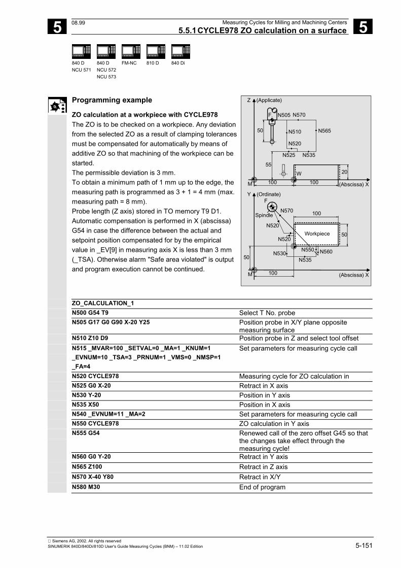
5 12.97 Measuring Cycles for Milling and Machining Centers5.5.1CYCLE978 ZO calculation on a surface
5
840 DNCU 571
840 DNCU 572NCU 573
FM-NC
810 D
840 Di
Siemens AG, 2002. All rights reservedSINUMERIK 840D/840Di/810D User's Guide Measuring Cycles (BNM) – 11.02 Edition 5-151
Programming example
ZO calculation at a workpiece with CYCLE978 The ZO is to be checked on a workpiece. Any deviationfrom the selected ZO as a result of clamping tolerancesmust be compensated for automatically by means ofadditive ZO so that machining of the workpiece can bestarted. The permissible deviation is 3 mm.To obtain a minimum path of 1 mm up to the edge, themeasuring path is programmed as 3 + 1 = 4 mm (max.measuring path = 8 mm). Probe length (Z axis) stored in TO memory T9 D1. Automatic compensation is performed in X (abscissa)G54 in case the difference between the actual andsetpoint position compensated for by the empiricalvalue in _EV[9] in measuring axis X is less than 3 mm(_TSA). Otherwise alarm "Safe area violated" is outputand program execution cannot be continued.
Y (Ordinate)
(Abscissa) X
F
SpindleN570
N520
N520
100
50Workpiece
N560N550
N535N530
50
M 100
Z (Applicate)
(Abscissa) X
N570N505F
50 N510 N565
N520
N535N525
55
100 100
20
M
W
ZO_CALCULATION_1 N500 G54 T9 Select T No. probe N505 G17 G0 G90 X-20 Y25 Position probe in X/Y plane opposite
measuring surface N510 Z10 D9 Position probe in Z and select tool offset N515 _MVAR=100 _SETVAL=0 _MA=1 _KNUM=1
_EVNUM=10 _TSA=3 _PRNUM=1 _VMS=0 _NMSP=1_FA=4
Set parameters for measuring cycle call
N520 CYCLE978 Measuring cycle for ZO calculation in N525 G0 X-20 Retract in X axis N530 Y-20 Position in Y axis N535 X50 Position in X axis N540 _EVNUM=11 _MA=2 Set parameters for measuring cycle call N550 CYCLE978 ZO calculation in Y axis N555 G54 Renewed call of the zero offset G45 so that
the changes take effect through themeasuring cycle!
N560 G0 Y-20 Retract in Y axis N565 Z100 Retract in Z axis N570 X-40 Y80 Retract in X/Y N580 M30 End of program
08.99
5 Measuring Cycles for Milling and Machining Centers 12.97 5.5 CYCLE978 Workpiece measurement: Surface
5
840 DNCU 571
840 DNCU 572NCU 573
FM-NC
810 D
840 Di
Siemens AG, 2002. All rights reserved5-152 SINUMERIK 840D/840Di/810D User's Guide Measuring Cycles (BNM) – 11.02 Edition
5.5.2 CYCLE978 Single-point measurement
Function
This measuring cycle determines the actual value of theworkpiece in the measuring axis selected relative to theworkpiece zero as well as the difference between setand actual values. An empirical value stored in the GUD5 module issubsequently taken into account with the correct sign. Optionally, averaging is performed over a number ofparts and the tolerance bands are checked. Depending on the definition of _KNUM, no automaticoffset, length compensation or radius compensation iscarried out. Precondition The probe must be called with tool length offset.Permissible tool types:• 1x0 or, for measuring cycles SW 4 and higher, 710
(3D probe)• In measuring cycle SW 5.4 and higher � 500 or in
measuring cycle SW 6.2 and higher � also 580 withtool cutting edge positions 5 to 8 under theconditions stated in Section 5.1.
11.02
5 12.97 Measuring Cycles for Milling and Machining Centers 5.5 CYCLE978 Workpiece measurement: Surface
5
840 DNCU 571
840 DNCU 572NCU 573
FM-NC
810 D
840 Di
Siemens AG, 2002. All rights reservedSINUMERIK 840D/840Di/810D User's Guide Measuring Cycles (BNM) – 11.02 Edition 5-153
Parameters
_MVAR 0 1000
Measure surfaceMeasure surface with differential measurement
_SETVAL REAL Setpoint (acc. to drawing) _MA 1...3 Number of measuring axis _KNUM 0 No automatic
tool offset;>0 Automatic tool offset
With/without automatic tool offset
_TNUM Integer, positive Tool number for automatic tool offset _TNAME STRING[32] Tool name for automatic tool offset
(alternative to _TNUM with tool managementactive)
These following additional parameters are also valid: _VMS, _CORA, _TZL, _TMV, _TUL, _TLL, _TDIF,_TSA, _FA, _PRNUM, _EVNUM, _NMSP and _K. See Sections 2.2 and 2.3.
Procedure
Position before the cycle is called The probe must be positioned facing the surface to bemeasured. Position after the cycle has terminated On completion of the measurement, the probe ispositioned facing the measurement surface at a distancecorresponding to _FA ⋅ 1 mm.
Notice!Precise measurement is only possible with a probecalibrated under the measurement conditions, i.e.working plane, orientation of the spindle in the plane andmeasuring velocity are the same for both measurementand calibration. Deviations can cause additionalmeasuring errors.
11.02
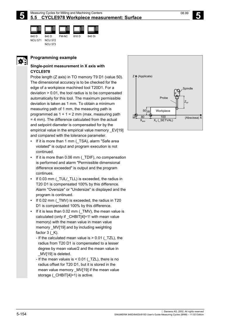
5 Measuring Cycles for Milling and Machining Centers 12.97 5.5 CYCLE978 Workpiece measurement: Surface
5
840 DNCU 571
840 DNCU 572NCU 573
FM-NC
810 D
840 Di
Siemens AG, 2002. All rights reserved5-154 SINUMERIK 840D/840Di/810D User's Guide Measuring Cycles (BNM) – 11.02 Edition
Programming example
Single-point measurement in X axis withCYCLE978 Probe length (Z axis) in TO memory T9 D1 (value 50). The dimensional accuracy is to be checked for theedge of a workpiece machined tool T20D1. For adeviation > 0.01, the tool radius is to be compensatedautomatically for this tool. The maximum permissibledeviation is taken as 1 mm. To obtain a minimummeasuring path of 1 mm, the measuring path isprogrammed as 1 + 1 = 2 mm (max. measuring path= 4 mm). The difference calculated from the actualand setpoint diameter is compensated for by theempirical value in the empirical value memory _EV[19]and compared with the tolerance parameter.• If it is more than 1 mm (_TSA), alarm "Safe area
violated" is output and program execution is notcontinued.
• If it is more than 0.06 mm (_TDIF), no compensationis performed and alarm "Permissible dimensionaldifference exceeded" is output and the programcontinues.
• If 0.03 mm (_TUL/_TLL) is exceeded, the radius inT20 D1 is compensated 100% by this difference.Alarm "Oversize" or "Undersize" is displayed and theprogram is continued.
• If 0.02 mm (_TMV) is exceeded, the radius in T20D1 is compensated 100% by this difference.
• If it is less than 0.02 mm (_TMV), the mean value iscalculated (only if _CHBIT[4]=1! with mean valuememory) with the mean value in mean valuememory _MV[19] and by including weightingfactor 3 (_K).- If the calculated mean value is > 0.01 (_TZL), the radius from T20 D1 is compensated to a lesser degree by mean value/2 and the mean value in _MV[19] is deleted.- If the mean values is < 0.01 (_TZL), there is no radius offset for T20 D1, but it is stored in the mean value memory _MV[19] if the mean value storage (_CHBIT[4]=1) is active.
(Abscissa) X
Z (Applicate)
Spindle
ProbeF
ZSF
Workpiece50 W
M 80 100XMW XS (_SETVAL)
08.99
5 12.97 Measuring Cycles for Milling and Machining Centers 5.5 CYCLE978 Workpiece measurement: Surface
5
840 DNCU 571
840 DNCU 572NCU 573
FM-NC
810 D
840 Di
Siemens AG, 2002. All rights reservedSINUMERIK 840D/840Di/810D User's Guide Measuring Cycles (BNM) – 11.02 Edition 5-155
SINGLE_POINT_MEASUREMENTN500 G54 T9 Select T No. probeN505 G17 G0 G90 X120 Y150 Position probe in X/Y plane opposite
measuring pointN510 Z40 D1 Position Z axis on level with measuring point
and select tool offsetN515 _MVAR=0 _SETVAL=100 _TUL=0.03 _TLL=-0.03_MA=1 _KNUM=2001 _TNUM=20 _EVNUM=20 _K=3_TZL=0.01 _TMV=0.02 _TDIF=0.06 _TSA=1 _PRNUM=1_VMS=0 _NMSP=1 _FA=2
Set parameters for measuring cycle call
N520 CYCLE978 Measuring cycle for single-pointmeasurement in X axis
N525 G0 Z160 Run up Z axisN580 M30 End of program
08.99
5 Measuring Cycles for Milling and Machining Centers 12.97 5.6 CYCLE979 Workpiece measurement: Hole/shaft/groove/web
5
840 DNCU 571
840 DNCU 572NCU 573
FM-NC
810 D
840 Di
Siemens AG, 2002. All rights reserved5-156 SINUMERIK 840D/840Di/810D User's Guide Measuring Cycles (BNM) – 11.02 Edition
5.6 CYCLE979 Workpiece measurement: Hole/shaft/groove/web(at a random angle)
Programming
CYCLE979
Function
A hole or shaft is determined by this cycle by means ofthree-point or four-point measurement. It is thuspossible to measure circle segments, the center pointof which is located well outside the machine.
Measurement at points P1, P2, P3 and P4 is performedat random angles (2D = two-dimensional; measure in 2axes simultaneously, depending on the angle ofmeasurement).
The probe is positioned from P1 to P2, from P2 to P3and from P3 to P4 with circular interpolation (withmeasurements of holes and shafts). The _FA distancebetween probe and the contour is maintained.
On completion of the cycle, the probe is facing P3 (orP4; in the case of groove and web measurements, it isfacing P2) at a distance corresponding to _FA.
PreconditionThe probe must be positioned in the vicinity of P1 at thedesired depth, so that point P1 can be approachedwithout collision with linear interpolation from thatposition.
05.98
5 12.97 Measuring Cycles for Milling and Machining Centers 5.6 CYCLE979 Workpiece measurement: Hole/shaft/groove/web
5
840 DNCU 571
840 DNCU 572NCU 573
FM-NC
810 D
840 Di
Siemens AG, 2002. All rights reservedSINUMERIK 840D/840Di/810D User's Guide Measuring Cycles (BNM) – 11.02 Edition 5-157
Result parameters
Depending on the measurement variant, CYCLE979supplies the following values as results in the GUD5module:
_OVR [0] REAL Setpoint diameter/width hole, shaft, groove, web_OVR [1] REAL Setpoint center point/center in abscissa_OVR [2] REAL Setpoint center point/center in ordinate_OVR [4] REAL Actual value diameter/width hole, shaft, groove, web_OVR [5] REAL Actual value center point/center in abscissa_OVR [6] REAL Actual value center point/center in ordinate_OVR [8] 1) REAL Upper tolerance limit for diameter/width hole, shaft, groove, web_OVR [12] 1) REAL Lower tolerance limit for diameter/width hole, shaft, groove, web_OVR [16] REAL Difference diameter/width hole, shaft, groove, web_OVR [17] REAL Difference center point/center in abscissa_OVR [18] REAL Difference center point/center in ordinate_OVR [20] 1) REAL Offset value_OVR [27] 1) REAL Zero offset area_OVR [28] 1) REAL Safe area_OVR [29] 1) REAL Permissible dimension difference_OVR [30] 1) REAL Empirical value_OVR [31] 1) REAL Mean value_OVI [0] INTEGER D number or ZO number_OVI [2] INTEGER Measuring cycle number_OVI [4] 1) INTEGER Weighting factor_OVI [5] INTEGER Measuring probe number_OVI [6] 1) INTEGER Mean value memory number_OVI [7] 1) INTEGER Empirical value memory number_OVI [8] INTEGER Tool number_OVI [9] INTEGER Alarm number
_OVI [11] 2) INTEGER Status offset request
1) For workpiece measurement with tool offset only2) For measuring cycle SW 6.2 and higher; only for
zero offset
11.02
5 Measuring Cycles for Milling and Machining Centers 12.97 5.6 CYCLE979 Workpiece measurement: Hole/shaft/groove/web
5
840 DNCU 571
840 DNCU 572NCU 573
FM-NC
810 D
840 Di
Siemens AG, 2002. All rights reserved5-158 SINUMERIK 840D/840Di/810D User's Guide Measuring Cycles (BNM) – 11.02 Edition
Applicable probe types
The measuring cycle operates with the following probetypes which are coded via parameter _PRNUM:
• Multidirectional probe• Bidirectional probe• Monodirectional probe This parameter also contains the specification for three-point and four-point measurements and has thefollowing values:
Digit Meaning 4 3 2 1 0 Three-point measurement 1 Four-point measurement 0 Multidirectional probe 1 Monodirectional probe - - Probe number (two digits)
Measurement variants and prepositioning
CYCLE979 permits the following measurement variantswhich are specified via parameter _MVAR.
Value Measurement variant Prepositioningin plane
1 Measure hole with tool offset In hole at measuring height 2 Measure shaft with tool offset Near P1 at measuring height 3 Measure groove with tool offset In groove at measuring height 4 Measure web with tool offset Near P1 at measuring height 101 ZO calculation in hole with ZO compensation In hole at measuring height 102 ZO calculation on shaft with ZO compensation Near P1 at measuring height 103 ZO calculation in groove with ZO compensation In groove at measuring height 104 ZO calculation on web with ZO compensation Near P1 at measuring height
10.00
5 12.97 Measuring Cycles for Milling and Machining Centers 5.6.1CYCLE979 Measure hole, shaft, groove, web
5
840 DNCU 571
840 DNCU 572NCU 573
FM-NC
810 D
840 Di
Siemens AG, 2002. All rights reservedSINUMERIK 840D/840Di/810D User's Guide Measuring Cycles (BNM) – 11.02 Edition 5-159
5.6.1 CYCLE979 Measure hole, shaft, groove, web
Function
Measure hole or shaft This measuring cycle gauges• within the hole or• when contouring the shaft. The position of these points is determined by initialangle _STA1 and indexing angle _INCA. These fourmeasured values are used to calculate the actual valueof the diameter and position of the center point in theabscissa and ordinate relative to the workpiece zero. Measure groove or web This measuring cycle gauges points P1 and P2 insidethe groove or web. These measured values are used tocalculate the actual value of the groove/web width aswell as the position of the groove/web center point in themeasuring axis relative to the workpiece zero. Options for hole and shaft diameter, groove orweb width• An empirical value stored in the GUD5 module is
subsequently taken into account with the correctsign.
• A mean value derivation over several parts ispossible as an option.
• Depending on the definition of _KNUM, no automaticoffset is performed or, alternatively, lengthcompensation or radius compensation (differencehalved) is carried out.
Precondition The probe must be called with tool length offset.Permissible tool types:• 1x0 or, for measuring cycles SW 4 and higher, 710
(3D probe)• in measuring cycle SW 5.4 and higher � 500 or in
measuring cycle SW 6.2 and higher � also 580 withtool cutting edge positions 5 to 8 under theconditions stated in Section 5.1.
11.02
5 Measuring Cycles for Milling and Machining Centers 12.97 5.6.1CYCLE979 Measure hole, shaft, groove, web
5
840 DNCU 571
840 DNCU 572NCU 573
FM-NC
810 D
840 Di
Siemens AG, 2002. All rights reserved5-160 SINUMERIK 840D/840Di/810D User's Guide Measuring Cycles (BNM) – 11.02 Edition
Parameters
_MVAR 1 2 3 4
Measure holeMeasure shaftMeasure grooveMeasure web
_SETVAL REAL Setpoint = diameter/width (acc. to drawing) _CPA REAL Center point abscissa (referred to workpiece zero) _CPO REAL Center point ordinate (referred to workpiece zero) _STA1 0...360 degrees Starting angle _ID REAL Incremental infeed of the applicates with sign
(measure only in web) _INCA 0...360 degrees Indexing angle
(only for measuring hole/shaft) _KNUM 0 No automatic
tool offset;>0 Automatic tool offset
With/without automatic tool offset
_TNUM Integer, positive Tool number for automatic tool offset _TNAME STRING[32] Tool name for automatic tool offset
(alternative to _TNUM with tool managementactive)
These following additional parameters are also valid: _VMS, _RF, _CORA, _TZL, _TMV, _TUL, _TLL, _TDIF,_TSA, _FA, _PRNUM, _EVNUM, _NMSP and _K. See Sections 2.2 and 2.3.
Procedure
Position before the cycle is called The probe must be positioned facing P1 and the probe ballat the measurement level. Position after the cycle has terminated formeasuring the hole/shaft On completion of the measuring process, the probe ispositioned facing P3 (or P4 for four-point measurement)at a distance corresponding to _FA ⋅ 1 mm. Position after the cycle has terminated formeasuring groove/web On completion of the measuring process, the probe ispositioned opposite P2 at a distance corresponding to _FA.
Notice!Precise measurement is only possible with a probecalibrated under the measurement conditions, i.e. workingplane, orientation of the spindle in the plane and measuringvelocity are the same for both measurement andcalibration. Deviations can cause additional measuringerrors.
11.02
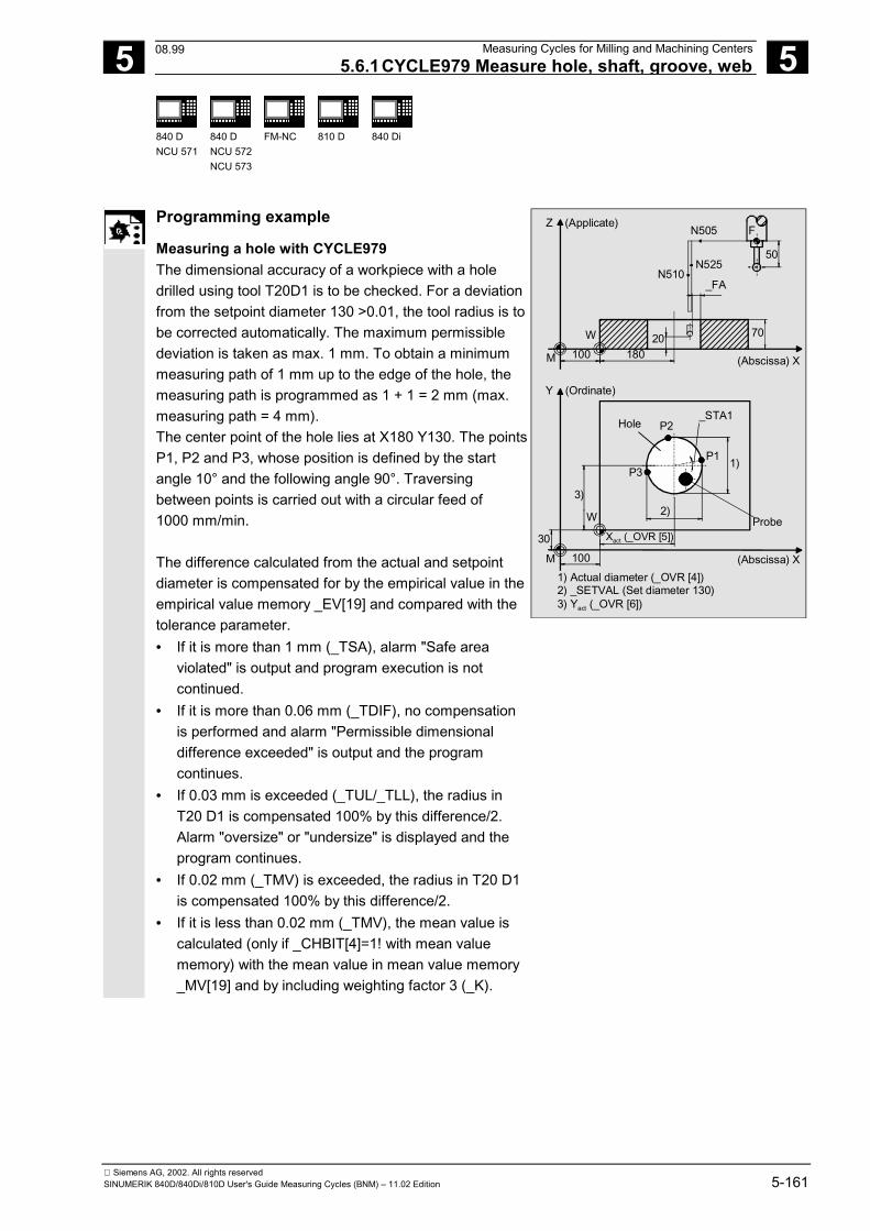
5 12.97 Measuring Cycles for Milling and Machining Centers 5.6.1CYCLE979 Measure hole, shaft, groove, web
5
840 DNCU 571
840 DNCU 572NCU 573
FM-NC
810 D
840 Di
Siemens AG, 2002. All rights reservedSINUMERIK 840D/840Di/810D User's Guide Measuring Cycles (BNM) – 11.02 Edition 5-161
Programming example
Measuring a hole with CYCLE979 The dimensional accuracy of a workpiece with a holedrilled using tool T20D1 is to be checked. For a deviationfrom the setpoint diameter 130 >0.01, the tool radius is tobe corrected automatically. The maximum permissibledeviation is taken as max. 1 mm. To obtain a minimummeasuring path of 1 mm up to the edge of the hole, themeasuring path is programmed as 1 + 1 = 2 mm (max.measuring path = 4 mm). The center point of the hole lies at X180 Y130. The pointsP1, P2 and P3, whose position is defined by the startangle 10° and the following angle 90°. Traversingbetween points is carried out with a circular feed of1000 mm/min. The difference calculated from the actual and setpointdiameter is compensated for by the empirical value in theempirical value memory _EV[19] and compared with thetolerance parameter.• If it is more than 1 mm (_TSA), alarm "Safe area
violated" is output and program execution is notcontinued.
• If it is more than 0.06 mm (_TDIF), no compensationis performed and alarm "Permissible dimensionaldifference exceeded" is output and the programcontinues.
• If 0.03 mm is exceeded (_TUL/_TLL), the radius inT20 D1 is compensated 100% by this difference/2.Alarm "oversize" or "undersize" is displayed and theprogram continues.
• If 0.02 mm (_TMV) is exceeded, the radius in T20 D1is compensated 100% by this difference/2.
• If it is less than 0.02 mm (_TMV), the mean value iscalculated (only if _CHBIT[4]=1! with mean valuememory) with the mean value in mean value memory_MV[19] and by including weighting factor 3 (_K).
(Abscissa) X
Y (Ordinate)
Hole_STA1
P2
P3P1 1)
2)W
3)
Xact (_OVR [5])30
M 100
Z (Applicate)N505
N510N525
_FA
F
50
M 100 18020W 70
(Abscissa) X
1) Actual diameter (_OVR [4])2) _SETVAL (Set diameter 130)3) Yact (_OVR [6])
Probe
08.99
5 Measuring Cycles for Milling and Machining Centers 12.97 5.6.1CYCLE979 Measure hole, shaft, groove, web
5
840 DNCU 571
840 DNCU 572NCU 573
FM-NC
810 D
840 Di
Siemens AG, 2002. All rights reserved5-162 SINUMERIK 840D/840Di/810D User's Guide Measuring Cycles (BNM) – 11.02 Edition
- If the mean value obtained is >0.01 (_TZL),the reduced compensation of the radius for T20 D1is the mean value/2 and the mean value is deletedin _MV[19].
- If the mean values is < 0.01 (_TZL), there is no radius offset for T20 D1, but it is stored in the mean value memory _MV[19] if the mean value storage (_CHBIT[4]=1) is active.
MEASURE_HOLE N500 G54 T9 Select T No. probe N505 G17 G0 G90 X120 Y150 Position probe in X/Y plane in vicinity of P1 N510 Z20 D1 Position Z axis at P1 level and select tool
offset N515_MVAR=1 _SETVAL=130 _TUL=0.03 _TLL=-0.03
_CPA=180 _CPO=130 _STA1=10 _INCA=90 _RF=1000_KNUM=2001 _TNUM=20 _EVNUM=20 _K=3 _TZL=0.01_TMV=0.02 _TDIF=0.06 _TSA=1 _PRNUM=1 _VMS=0_NMSP=1 _FA=2
Set parameters for measuring cycle call
N520 CYCLE979 Call measuring cycle for hole measurementin X/Y
N525 G0 Z160 Run up Z axis N570 M30 End of program
08.99
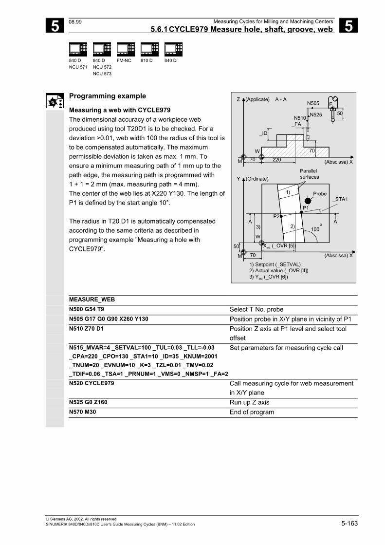
5 12.97 Measuring Cycles for Milling and Machining Centers 5.6.1CYCLE979 Measure hole, shaft, groove, web
5
840 DNCU 571
840 DNCU 572NCU 573
FM-NC
810 D
840 Di
Siemens AG, 2002. All rights reservedSINUMERIK 840D/840Di/810D User's Guide Measuring Cycles (BNM) – 11.02 Edition 5-163
Programming example
Measuring a web with CYCLE979 The dimensional accuracy of a workpiece webproduced using tool T20D1 is to be checked. For adeviation >0.01, web width 100 the radius of this tool isto be compensated automatically. The maximumpermissible deviation is taken as max. 1 mm. Toensure a minimum measuring path of 1 mm up to thepath edge, the measuring path is programmed with1 + 1 = 2 mm (max. measuring path = 4 mm). The center of the web lies at X220 Y130. The length ofP1 is defined by the start angle 10°. The radius in T20 D1 is automatically compensatedaccording to the same criteria as described inprogramming example "Measuring a hole withCYCLE979".
1) Setpoint (_SETVAL)2) Actual value (_OVR [4])3) Yact (_OVR [6])
Z (Applicate)
(Abscissa) X
FN505
N525N510_FA
_ID
50
W
M 70 220
(Abscissa) X
Y (Ordinate)Parallelsurfaces
Probe
P1_STA1
P2
3) 100°W
5070M
Xact (_OVR [5])
1)
2)A A
A - A
70
MEASURE_WEB N500 G54 T9 Select T No. probe N505 G17 G0 G90 X260 Y130 Position probe in X/Y plane in vicinity of P1 N510 Z70 D1 Position Z axis at P1 level and select tool
offset N515_MVAR=4 _SETVAL=100 _TUL=0.03 _TLL=-0.03
_CPA=220 _CPO=130 _STA1=10 _ID=35 _KNUM=2001_TNUM=20 _EVNUM=10 _K=3 _TZL=0.01 _TMV=0.02_TDIF=0.06 _TSA=1 _PRNUM=1 _VMS=0 _NMSP=1 _FA=2
Set parameters for measuring cycle call
N520 CYCLE979 Call measuring cycle for web measurementin X/Y plane
N525 G0 Z160 Run up Z axis N570 M30 End of program
08.99
5 Measuring Cycles for Milling and Machining Centers 12.97 5.6.2CYCLE979 ZO calculation in hole, shaft, groove, web
5
840 DNCU 571
840 DNCU 572NCU 573
FM-NC
810 D
840 Di
Siemens AG, 2002. All rights reserved5-164 SINUMERIK 840D/840Di/810D User's Guide Measuring Cycles (BNM) – 11.02 Edition
5.6.2 CYCLE979 ZO calculation in hole, shaft, groove, web
Function
ZO calculation in a hole or on a shaft This measuring cycle gauges• within the hole or• when contouring the shaft. These four measured values are used to calculate theactual hole/shaft diameter and the position of thehole/shaft center point in the abscissa and ordinaterelative to the workpiece zero. ZO calculation in a groove or on a web This measuring cycle gauges• within the groove or• on two parallel surfaces (web) The two measured values are used to calculate theactual groove/web width as well as the position of thegroove/web center point in the measuring axis relativeto the workpiece zero. The following applies to all ZO calculations: The difference is determined from the set center point(_CPA and _CPO) and the calculated center point. Depending on the definition of _KNUM, no automaticZO entry is performed or, alternatively, the measuringaxis difference is added in the specified ZO memory. Ifa fine offset is active (MD 18600:MM_FRAME_FINE_TRANS), an additive ZO will beimplemented in it, otherwise it is implemented in thecoarse offset. Precondition The probe must be called with tool length offset.Permissible tool types:• 1x0 or, for measuring cycles SW 4 and higher, 710
(3D probe)• in measuring cycle SW 5.4 and higher � 500 or in
measuring cycle SW 6.2 and higher � also 580 withtool cutting edge positions 5 to 8 under theconditions stated in Section 5.1.
11.02
5 12.97 Measuring Cycles for Milling and Machining Centers 5.6.2CYCLE979 ZO calculation in hole, shaft, groove, web
5
840 DNCU 571
840 DNCU 572NCU 573
FM-NC
810 D
840 Di
Siemens AG, 2002. All rights reservedSINUMERIK 840D/840Di/810D User's Guide Measuring Cycles (BNM) – 11.02 Edition 5-165
Parameters
_MVAR 101 102103104
ZO calculation in a hole with ZO compensationZO calculation on a shaft with ZO compensationZO calculation in a groove with ZO compensationZO calculation on a web with ZO compensation
_SETVAL REAL Setpoint for diameter/width _CPA REAL Center point abscissa (referred to workpiece zero) _CPO REAL Center point ordinate (referred to workpiece zero) _STA1 0...360 degrees Starting angle _ID REAL Incremental infeed of applicate with leading sign
(only for ZO calculation on a web) _INCA 0...360 degrees Indexing angle
(only for ZO calculation in hole or on shaft) _KNUM 0 no automatic
ZO compensation;1...99 automatic additive
ZO compensation in G54...G57, G505...G599
With/without automatic ZO calculation
Meas. cycles≥ SW 4.4
1000 automatic additive ZO compensation in channel-specific basic frame1)
Meas. cycles≥ SW 6.22)
1011...1026 automatic ZO compensation in 1st to 16th basic frame (channel) ($P_CHBFR[0]...$P_CHBFR[15])
1051...1066 automatic ZO compensation in 1st to 16th basic frame (global) ($P_NCBFR[0]...$P_NCBFR[15])
2000 automatic ZO compensation in system framescratching system frame ($P_SETFR)
9999 automatic ZO compensation in an active frame settable frames G54..G57, G505...G599 or
for G500 in last active basic frame according to $P_CHBFRMASK (most significant bit)
1) As of measuring cycles SW 5.3, compensation iscarried out in the last basic frame (per MD 28081:MM_NUM_BASE_FRAMES) if more than one isavailable. If measuring cycles higher than SW 5.3are used at a control with SW 4, parameter _SI[1]in the GUD 6 module must be set to 4!
2) Measuring cycles version SW 6.2 and highercan only be used with NCK-SW 6.3 andhigher!!
These following additional parameters are also valid: _VMS, _RF, _CORA, _TSA, _FA, _PRNUM and _NMSP. See Sections 2.2 and 2.3.
11.02
5 Measuring Cycles for Milling and Machining Centers 12.97 5.6.2CYCLE979 ZO calculation in hole, shaft, groove, web
5
840 DNCU 571
840 DNCU 572NCU 573
FM-NC
810 D
840 Di
Siemens AG, 2002. All rights reserved5-166 SINUMERIK 840D/840Di/810D User's Guide Measuring Cycles (BNM) – 11.02 Edition
Procedure
Position before the cycle is called The probe must be positioned facing P1 and the probeball at the measurement level. Position after the measuring cycle hasterminated with ZO calculation in hole or onshaft On completion of the measuring process, the probe ispositioned facing P3 (or P4 for four-point measurement)at a distance corresponding to _FA ⋅ 1 mm. Position after the measuring cycle hasterminated with ZO calculation in groove or onshaft On completion of the measuring process, the probe ispositioned facing P2 at a distance corresponding to_FA ⋅ 1 mm.
Notice!Precise measurement is only possible with a probecalibrated under the measurement conditions, i.e.working plane, orientation of the spindle in the planeand measuring velocity are the same for bothmeasurement and calibration. Deviations can causeadditional measuring errors.
11.02
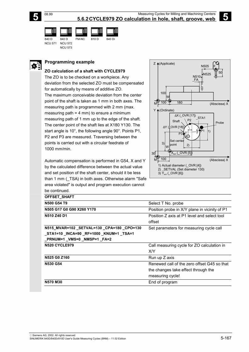
5 12.97 Measuring Cycles for Milling and Machining Centers 5.6.2CYCLE979 ZO calculation in hole, shaft, groove, web
5
840 DNCU 571
840 DNCU 572NCU 573
FM-NC
810 D
840 Di
Siemens AG, 2002. All rights reservedSINUMERIK 840D/840Di/810D User's Guide Measuring Cycles (BNM) – 11.02 Edition 5-167
Programming example
ZO calculation of a shaft with CYCLE979 The ZO is to be checked on a workpiece. Anydeviation from the selected ZO must be compensatedfor automatically by means of additive ZO.The maximum conceivable deviation from the centerpoint of the shaft is taken as 1 mm in both axes. Themeasuring path is programmed with 2 mm (max.measuring path = 4 mm) to ensure a minimummeasuring path of 1 mm up to the edge of the shaft.The center point of the shaft lies at X180 Y130. Thestart angle is 10°, the following angle 90°. Points P1,P2 and P3 are measured. Traversing between thepoints is carried out with a circular feedrate of1000 mm/min. Automatic compensation is performed in G54, X and Yby the calculated difference between the actual valueand set position of the shaft center, should it be lessthan 1 mm (_TSA) in both axes. Otherwise alarm "Safearea violated" is output and program execution cannotbe continued.
(Abscissa) X
Y (Ordinate)
∆Y (_OVR [18])
Set centerpoint3)
W
∆X (_OVR [17])
Shaft P2
P1 1)P3
2)
30
M 100
Xact (_OVR [5])
Z (Applicate)
(Abscissa) X
FN505
N525N510_FA
50
100W
M 100 180
1) Actual diameter (_OVR [4])2) _SETVAL (Set diameter 130)3) Yact (_OVR [6])
Probe_STA1
OFFSET_SHAFT N500 G54 T9 Select T No. probe N505 G17 G0 G90 X260 Y170 Position probe in X/Y plane in vicinity of P1 N510 Z40 D1 Position Z axis at P1 level and select tool
offset N515_MVAR=102 _SETVAL=130 _CPA=180 _CPO=130
_STA1=10 _INCA=90 _RF=1000 _KNUM=1 _TSA=1_PRNUM=1 _VMS=0 _NMSP=1 _FA=2
Set parameters for measuring cycle call
N520 CYCLE979 Call measuring cycle for ZO calculation inX/Y
N525 G0 Z160 Run up Z axis N530 G54 Renewed call of the zero offset G45 so that
the changes take effect through themeasuring cycle!
N570 M30 End of program
08.99
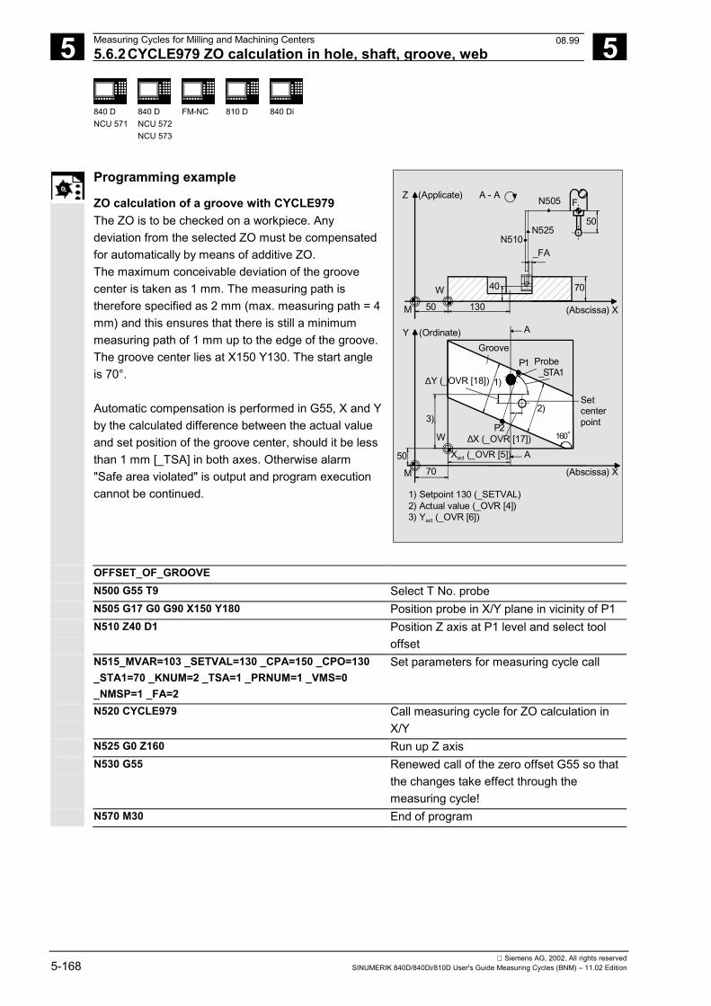
5 Measuring Cycles for Milling and Machining Centers 12.97 5.6.2CYCLE979 ZO calculation in hole, shaft, groove, web
5
840 DNCU 571
840 DNCU 572NCU 573
FM-NC
810 D
840 Di
Siemens AG, 2002. All rights reserved5-168 SINUMERIK 840D/840Di/810D User's Guide Measuring Cycles (BNM) – 11.02 Edition
Programming example
ZO calculation of a groove with CYCLE979 The ZO is to be checked on a workpiece. Anydeviation from the selected ZO must be compensatedfor automatically by means of additive ZO.The maximum conceivable deviation of the groovecenter is taken as 1 mm. The measuring path istherefore specified as 2 mm (max. measuring path = 4mm) and this ensures that there is still a minimummeasuring path of 1 mm up to the edge of the groove.The groove center lies at X150 Y130. The start angleis 70°. Automatic compensation is performed in G55, X and Y by the calculated difference between the actual valueand set position of the groove center, should it be lessthan 1 mm [_TSA] in both axes. Otherwise alarm"Safe area violated" is output and program executioncannot be continued.
(Abscissa) X
Y (Ordinate)
P1_STA1
160°P2
Xact (_OVR [5])50
W
70M
Z (Applicate)
(Abscissa) X
N505 F
50N525
N510_FA
M 50 130
70
A
40
A
A - A
W
∆X (_OVR [17])
∆Y (_OVR [18])
1) Setpoint 130 (_SETVAL)2) Actual value (_OVR [4])3) Yact (_OVR [6])
3)2)
1)
Setcenterpoint
GrooveProbe
OFFSET_OF_GROOVE N500 G55 T9 Select T No. probe N505 G17 G0 G90 X150 Y180 Position probe in X/Y plane in vicinity of P1 N510 Z40 D1 Position Z axis at P1 level and select tool
offset N515_MVAR=103 _SETVAL=130 _CPA=150 _CPO=130
_STA1=70 _KNUM=2 _TSA=1 _PRNUM=1 _VMS=0_NMSP=1 _FA=2
Set parameters for measuring cycle call
N520 CYCLE979 Call measuring cycle for ZO calculation inX/Y
N525 G0 Z160 Run up Z axis N530 G55 Renewed call of the zero offset G55 so that
the changes take effect through themeasuring cycle!
N570 M30 End of program
08.99
5 12.97 Measuring Cycles for Milling and Machining Centers 5.7 CYCLE998 Angular measurement (ZO calculation)
5
840 DNCU 571
840 DNCU 572NCU 573
FM-NC
810 D
840 Di
Siemens AG, 2002. All rights reservedSINUMERIK 840D/840Di/810D User's Guide Measuring Cycles (BNM) – 11.02 Edition 5-169
5.7 CYCLE998 Angular measurement (ZO calculation)
Programming
CYCLE998
Function
This cycle makes it possible to determine the angularposition of a workpiece relative to the set angle value_STA 1 to the offset axis. An empirical value stored in the GUD5 module issubsequently taken into account with the correct sign. The multiplying factor for measurement path 1 mmmakes it possible to take into account the scatter band ofthe blanks (set value). Depending on the definition of _KNUM either noautomatic ZO compensation is performed, or thedifference between the actual and setpoint value of theangle is added to the specified ZO memoryof the rotary axis. If a fine offset is active (MD 18600:MM_FRAME_FINE_TRANS), an additive ZO will beimplemented in it, otherwise it is implemented in thecoarse offset. This cycle can also be used to perform differentialmeasurements. In Measuring cycles SW 4.4 and higher, the angulardifference can be added to the rotary component of thespecified ZO memory (coordinate rotation).
2 angle measurement for measuring cycle SW 6.2and higherWith measuring variants _MVAR=106 and_MVAR=100106 it is possible calculated and correct theangular position of an oblique plane on a workpiece bymeasuring 3 points. The angles refer to rotation about theaxes or the active plane G17 to G19.Otherwise, the same conditions apply as for simple anglemeasurement.Additional data are required for the setpoint input of the2nd angle. A ZO is implemented in the rotary part of theset ZO memory (coordinate rotation).
11.02
5 Measuring Cycles for Milling and Machining Centers 12.97 5.7 CYCLE998 Angular measurement (ZO calculation)
5
840 DNCU 571
840 DNCU 572NCU 573
FM-NC
810 D
840 Di
Siemens AG, 2002. All rights reserved5-170 SINUMERIK 840D/840Di/810D User's Guide Measuring Cycles (BNM) – 11.02 Edition
Result parameters
CYCLE998 makes the following values available asresults in the GUD5 module:
_OVR [0] REAL Setpoint angle/setpoint angle between workpiece area and 1st axis of theplane (abscissa) of the active WCS1)
_OVR [1]1) REAL Setpoint angle between workpiece area and 2nd axis of the plane(ordinate) of the active WCS
_OVR [4] REAL Actual value angle/actual value angle between workpiece area and 1st axisof the plane (abscissa) of the active WCS1)
_OVR [5]1) REAL Actual value angle between workpiece area and 2nd axis of the plane(ordinate) of the active WCS
_OVR [16] REAL Difference angle/difference angle about 1st axis of the plane1)
_OVR [17]1) REAL Difference angle about 2nd axis of the plane _OVR [20] REAL Offset value angle
_OVR [21]1) REAL Offset value angle about 1st axis of the plane _OVR [22]1) REAL Offset value angle about 2nd axis of the plane _OVR [23]1) REAL Offset value angle about 3rd axis of the plane _OVR [28] REAL Safe area _OVR [30] REAL Empirical value _OVI [0] INTEGER ZO number _OVI [2] INTEGER Measuring cycle number _OVI [5] INTEGER Measuring probe number _OVI [7] INTEGER Empirical value memory number _OVI [9] INTEGER Alarm number _OVI [11]2) INTEGER Status offset request _OVI [12]2) INTEGER Internal error number of the measure function
1) As of measuring cycles SW 6.2 and higher;measuring variant _MVAR=x00106 only
2) For measuring cycle SW 6.2 and higher; only forzero offset
Differential measurement
Differential measurement means that measuring point 1is measured twice with a spindle reversal of 180°, i.e.rotation of probe through 180 degrees. This determinesthe trigger point for the measuring direction and thepositional deviation when measuring in the plane in themeasuring axis and stores it in the GUD6 module. An uncalibrated probe can therefore be used for themeasurement.
11.02
5 12.97 Measuring Cycles for Milling and Machining Centers 5.7 CYCLE998 Angular measurement (ZO calculation)
5
840 DNCU 571
840 DNCU 572NCU 573
FM-NC
810 D
840 Di
Siemens AG, 2002. All rights reservedSINUMERIK 840D/840Di/810D User's Guide Measuring Cycles (BNM) – 11.02 Edition 5-171
Precondition for differential measurement• Spindle orientation (with previously programmed
SPOS command) by NC• Bidirectional/multidirectional probe• Random positioning of probe in spindle between 0°
and 360° (min. every 90°) (all-round coverage). Preconditions for angular measurement• The probe must be positioned with tool length offset
and opposite the 1st measuring point.• Tool type 1x0 or 710 (3D probe) for measuring
cycles SW 4 and higher is permitted.As of measuring cycles SW 5.4, tool type 500 and asof measuring cycles SW 6.2 also 580 with tool edgepositions 5 to 8 is also possible under the conditionsstated in Section 5.1.
• Parameter _ID is used to specify the distance in theoffset axis between MP1 and MP2 (positive valuesonly).
• The cycle is capable of measuring a maximum angleof -45°...45°. However, the measurement can betaken from all sides.
• The angle between the offset axis and the workpieceedge is defined as the setpoint angle. The setpointhas a negative sign in the clockwise direction and apositive sign in the counterclockwise direction.
Applicable probe types
The measuring cycle operates with the following probetypes which are coded via parameter _PRNUM: • Multidirectional probe• Bidirectional probe• Monodirectional probe
Monodirectional probes must be calibrated! Theseprobes cannot be used to take differentialmeasurements!
11.02
5 Measuring Cycles for Milling and Machining Centers 12.97 5.7 CYCLE998 Angular measurement (ZO calculation)
5
840 DNCU 571
840 DNCU 572NCU 573
FM-NC
810 D
840 Di
Siemens AG, 2002. All rights reserved5-172 SINUMERIK 840D/840Di/810D User's Guide Measuring Cycles (BNM) – 11.02 Edition
Measurement variantsCYCLE998 permits the following measurement variantswhich are specified via parameter _MVAR.
Value Measurement variant105 Angle measurement, ZO calculation
1105 Angle measurement with differential measurement, ZO calculation1001051) Angle measurement, ZO calculation with paraxial positioning of measuring point 1 to
measuring point 2 in the offset axis1011051) Angle measurement with difference measurement, ZO calculation and paraxial
positioning of measuring point 1 to measuring point 2 in the offset axis1061) 2 angle measurement, ZO calculation
1001061) 2 angle measurement, ZO calculation with paraxial positioning between measuringpoints 1, 2, 3
When differential measurement (_MVAR=1105) isselected only MP1 is measured twice.1) Measuring cycles SW 6.2. and higher
Parameters
_MVAR 105
1105
Angular measurement ZO calculation with ZOcompensationAngular measurement with differential measure-ment, ZO calculation with ZO compensation
Meas. cycles≥ SW 6.22)
106 2 angle measurement (oblique plane),ZO calculation with ZO
100105or 100106
6th digit=1:Measuring point to measuring point positioningis paraxial
105or 106
6th digit=0:Positioning is effected taking account ofthe set angle and distances and the deviationpermissible in _TSA
_SETVAL REAL Setpoint (axis position) in measuring point 1 in themeasuring axisFor measurement variant 106: expected positionon the workpiece surface in measuring point P1 onthe applicate (no meaning if _MVAR=1xx10x)
_STA1 REAL Setpoint angle or angle about 1st axis of the plane_INCAMeas. cycles≥ SW 6.22)
REAL Only if _MVAR=x00106:Setpoint angle about 2nd axis of the plane
_MA 102 or 201 Number of offset axis and measuring axis102...302 (Measuring cyclesSW 4.4 and higher)
If _MVAR=x00106: No entry required, applicate isalways measuring axis
_MDMeas. cycles≥ SW 6.22)
0 positive measuring direction1 negative measuring direction
Measuring direction in the measuring axis(only relevant if _MVAR=10x10x)
11.02
5 12.97 Measuring Cycles for Milling and Machining Centers 5.7 CYCLE998 Angular measurement (ZO calculation)
5
840 DNCU 571
840 DNCU 572NCU 573
FM-NC
810 D
840 Di
Siemens AG, 2002. All rights reservedSINUMERIK 840D/840Di/810D User's Guide Measuring Cycles (BNM) – 11.02 Edition 5-173
_ID REAL (without sign) Distance between measuring points P1 and P2 inthe offset axisIf _MVAR=x00106: Distance between measuringpoints P1 and P2 in the 1st axis of the plane(abscissa)
_SETV[0]Meas. cycles≥ SW 6.22)
REAL (without sign) Only if _MVAR=x00106:Distance between measuring points P1 and P3 inthe 2nd axis of the plane (ordinate)
_RAMeas. cycles≥ SW 4.42)
0 Compensation is performed in the rotary com-ponent of the ZO compensation defined in _KNUM
>0 Number of the rotary axis,Compensation implemented in the translation partdefined in _KNUM of the rotary axis determined by_RA (not if _MVAR=x00106)
_KNUM 0 no automaticZO compensation;
1...99 automatic ZO compensation in G54...G57, G505...G599
With/without automatic ZO calculation
Meas. cycles≥ SW 4.42)
1000 automatic additive ZO compensation in channel-specific basic frame1)
Meas. cycles≥ SW 6.22
1011...1026 automatic ZO compensation in 1st to 16th basic frame (channel) ($P_CHBFR[0]...$P_CHBFR[15])
1051...1066 automatic ZO compensation in 1st to 16th basic frame (global) ($P_NCBFR[0]...$P_NCBFR[15])
2000 automatic ZO compensation in system framescratching system frame ($P_SETFR)
9999 automatic ZO compensation in an active frame settable frames G54..G57, G505...G599 or
for G500 in last active basic frame according to $P_CHBFRMASK (most significant bit)
1) As of measuring cycles SW 5.3, compensation iscarried out in the last channel-specific basicframe (per MD 28081:MM_NUM_BASE_FRAMES) if more than one isavailable. If measuring cycles higher than SW 5.3are used at a control with SW 4, parameter _SI[1]in the GUD 6 module must be set to 4!
2) Measuring cycles version SW 6.2 and highercan only be used with NCK-SW 6.3 and higher.
3) Only for angle measurement with offset in the ZOmemory of a rotary axis.
These following additional parameters are also valid:_VMS, _CORA, _TSA, _FA, _PRNUM, _EVNUM and _NMSP.See Sections 2.2 and 2.3.Notice!Precise angle definition requires a minimum surfacefinish at least at the measuring points. The distancesbetween the measuring points must be selected aslarge as possible.
11.02
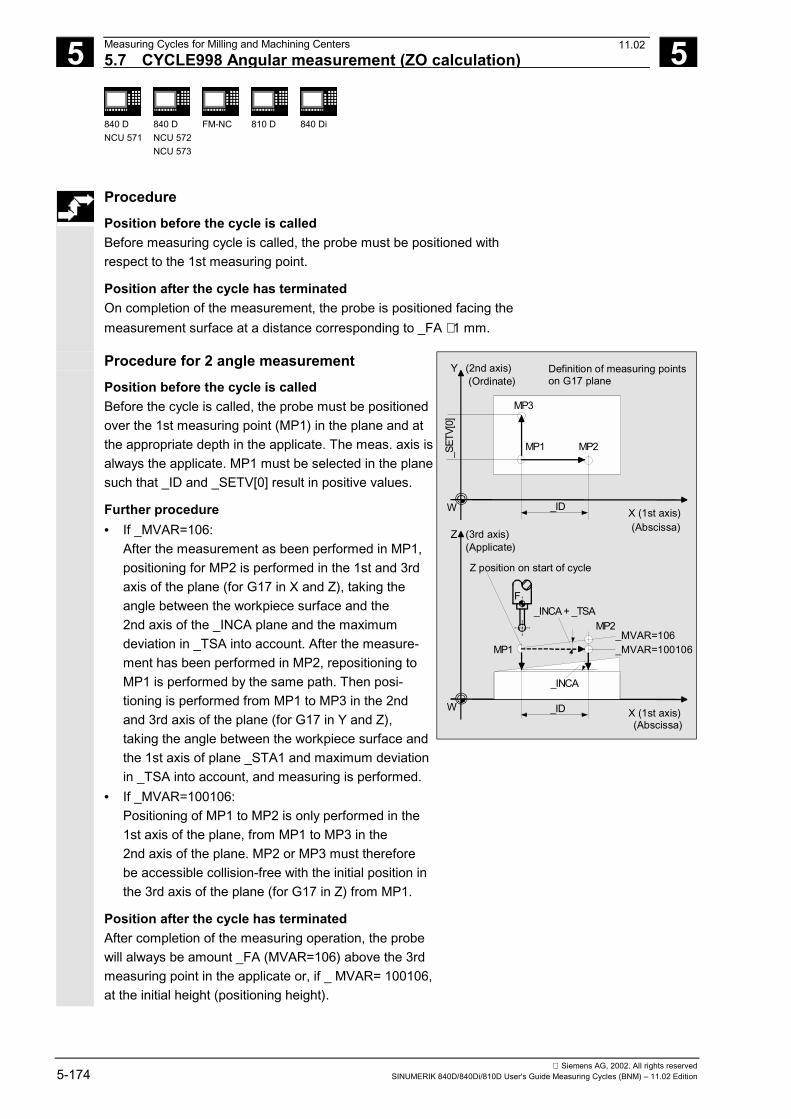
5 Measuring Cycles for Milling and Machining Centers 12.97 5.7 CYCLE998 Angular measurement (ZO calculation)
5
840 DNCU 571
840 DNCU 572NCU 573
FM-NC
810 D
840 Di
Siemens AG, 2002. All rights reserved5-174 SINUMERIK 840D/840Di/810D User's Guide Measuring Cycles (BNM) – 11.02 Edition
ProcedurePosition before the cycle is calledBefore measuring cycle is called, the probe must be positioned withrespect to the 1st measuring point.
Position after the cycle has terminatedOn completion of the measurement, the probe is positioned facing themeasurement surface at a distance corresponding to _FA ⋅ 1 mm.
Procedure for 2 angle measurementPosition before the cycle is calledBefore the cycle is called, the probe must be positionedover the 1st measuring point (MP1) in the plane and atthe appropriate depth in the applicate. The meas. axis isalways the applicate. MP1 must be selected in the planesuch that _ID and _SETV[0] result in positive values.
Further procedure• If _MVAR=106:
After the measurement as been performed in MP1,positioning for MP2 is performed in the 1st and 3rdaxis of the plane (for G17 in X and Z), taking theangle between the workpiece surface and the2nd axis of the _INCA plane and the maximumdeviation in _TSA into account. After the measure-ment has been performed in MP2, repositioning toMP1 is performed by the same path. Then posi-tioning is performed from MP1 to MP3 in the 2ndand 3rd axis of the plane (for G17 in Y and Z),taking the angle between the workpiece surface andthe 1st axis of plane _STA1 and maximum deviationin _TSA into account, and measuring is performed.
• If _MVAR=100106:Positioning of MP1 to MP2 is only performed in the1st axis of the plane, from MP1 to MP3 in the2nd axis of the plane. MP2 or MP3 must thereforebe accessible collision-free with the initial position inthe 3rd axis of the plane (for G17 in Z) from MP1.
Position after the cycle has terminatedAfter completion of the measuring operation, the probewill always be amount _FA (MVAR=106) above the 3rdmeasuring point in the applicate or, if _ MVAR= 100106,at the initial height (positioning height).
X (1st axis)W
Y (2nd axis)
MP2
MP3
MP1_S
ETV[
0]
_INCA + _TSAMP2
MP1
X (1st axis)W
Z (3rd axis)
_ID
_ID
Z position on start of cycle
_MVAR=106_MVAR=100106
_INCA
F
(Ordinate)
(Abscissa)
(Abscissa)
(Applicate)
Definition of measuring pointson G17 plane
11.02
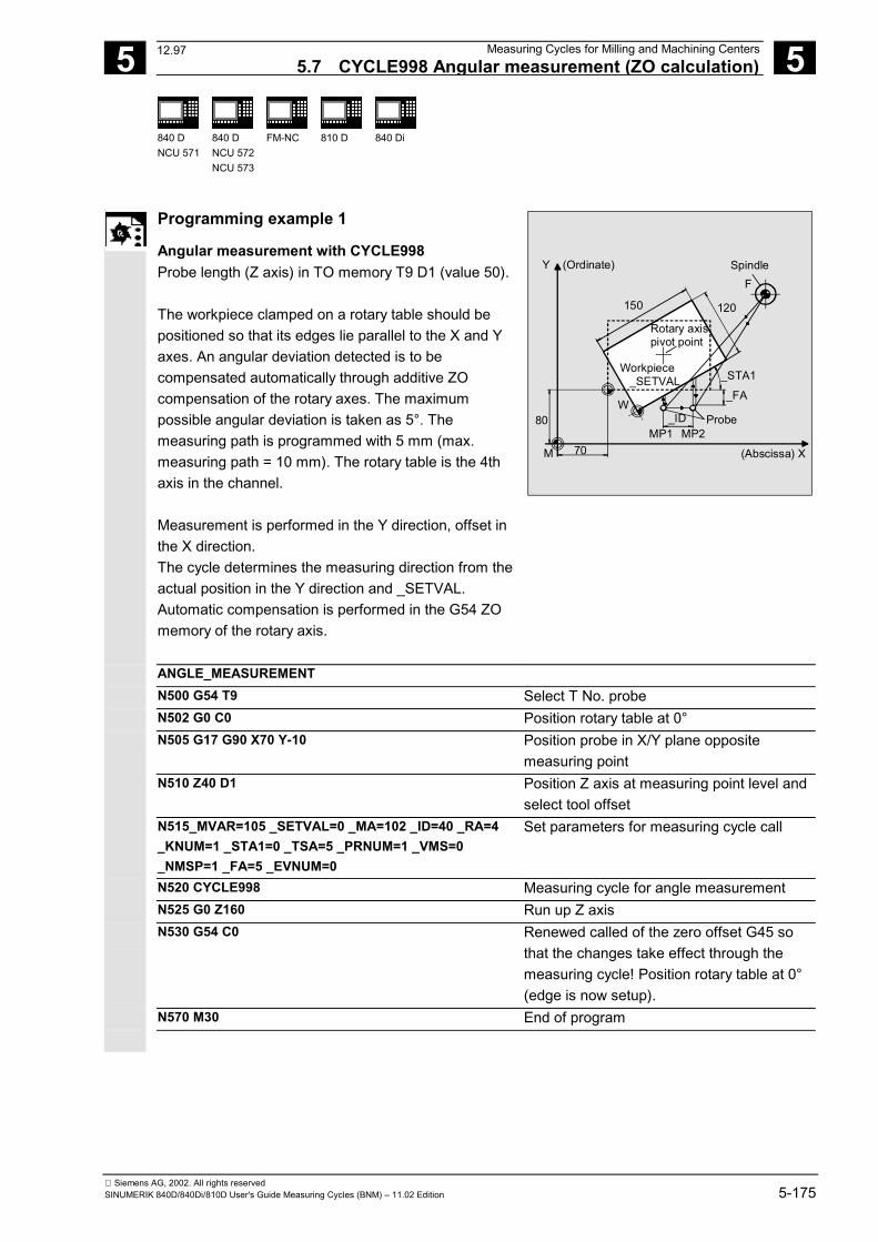
5 12.97 Measuring Cycles for Milling and Machining Centers
5.7 CYCLE998 Angular measurement (ZO calculation) 5
840 DNCU 571
840 DNCU 572NCU 573
FM-NC
810 D
840 Di
Siemens AG, 2002. All rights reservedSINUMERIK 840D/840Di/810D User's Guide Measuring Cycles (BNM) – 11.02 Edition 5-175
Programming example 1
Angular measurement with CYCLE998Probe length (Z axis) in TO memory T9 D1 (value 50).
The workpiece clamped on a rotary table should bepositioned so that its edges lie parallel to the X and Yaxes. An angular deviation detected is to becompensated automatically through additive ZOcompensation of the rotary axes. The maximumpossible angular deviation is taken as 5°. Themeasuring path is programmed with 5 mm (max.measuring path = 10 mm). The rotary table is the 4thaxis in the channel.
Measurement is performed in the Y direction, offset inthe X direction.The cycle determines the measuring direction from theactual position in the Y direction and _SETVAL.Automatic compensation is performed in the G54 ZOmemory of the rotary axis.
Y (Ordinate)
(Abscissa) X
SpindleF
120150
Rotary axispivot point
Workpiece _SETVAL _STA1
_FA
Probe_IDW
80MP1 MP2
70M
ANGLE_MEASUREMENTN500 G54 T9 Select T No. probeN502 G0 C0 Position rotary table at 0°N505 G17 G90 X70 Y-10 Position probe in X/Y plane opposite
measuring pointN510 Z40 D1 Position Z axis at measuring point level and
select tool offsetN515_MVAR=105 _SETVAL=0 _MA=102 _ID=40 _RA=4_KNUM=1 _STA1=0 _TSA=5 _PRNUM=1 _VMS=0_NMSP=1 _FA=5 _EVNUM=0
Set parameters for measuring cycle call
N520 CYCLE998 Measuring cycle for angle measurementN525 G0 Z160 Run up Z axisN530 G54 C0 Renewed called of the zero offset G45 so
that the changes take effect through themeasuring cycle! Position rotary table at 0°(edge is now setup).
N570 M30 End of program
12.97
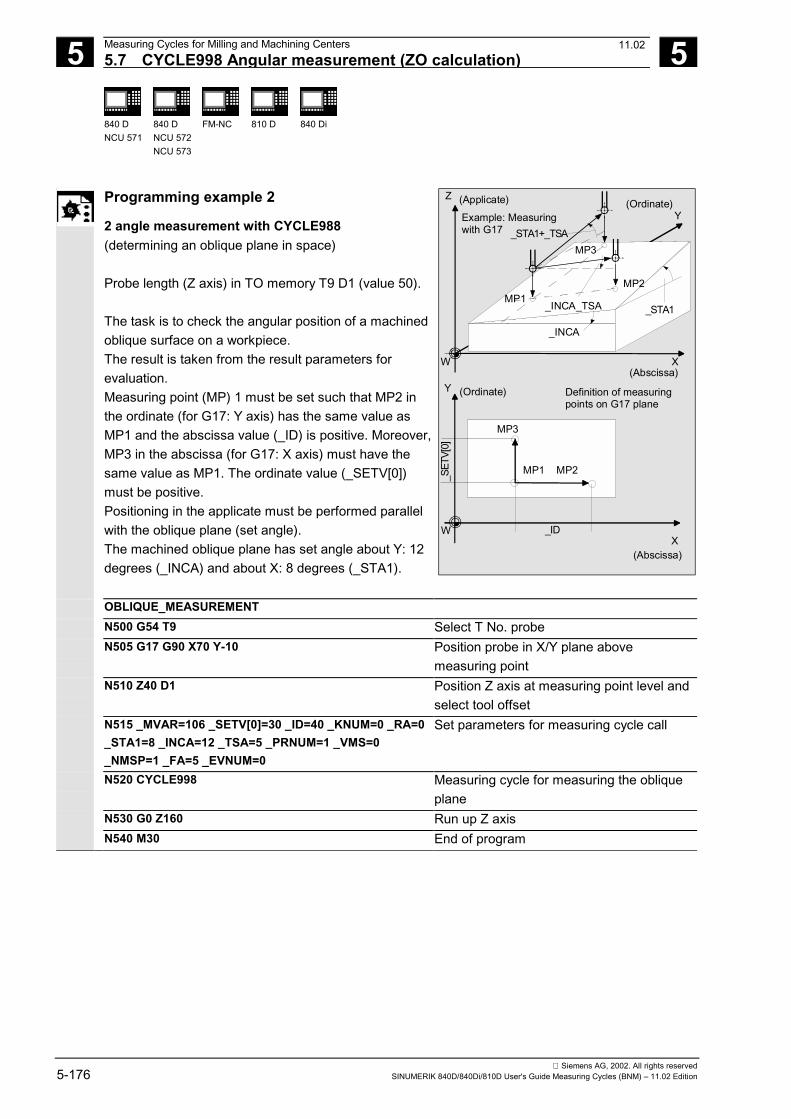
5 Measuring Cycles for Milling and Machining Centers 12.97 5.7 CYCLE998 Angular measurement (ZO calculation)
5
840 DNCU 571
840 DNCU 572NCU 573
FM-NC
810 D
840 Di
Siemens AG, 2002. All rights reserved5-176 SINUMERIK 840D/840Di/810D User's Guide Measuring Cycles (BNM) – 11.02 Edition
Programming example 2
2 angle measurement with CYCLE988(determining an oblique plane in space)
Probe length (Z axis) in TO memory T9 D1 (value 50).
The task is to check the angular position of a machinedoblique surface on a workpiece.The result is taken from the result parameters forevaluation.Measuring point (MP) 1 must be set such that MP2 inthe ordinate (for G17: Y axis) has the same value asMP1 and the abscissa value (_ID) is positive. Moreover,MP3 in the abscissa (for G17: X axis) must have thesame value as MP1. The ordinate value (_SETV[0])must be positive.Positioning in the applicate must be performed parallelwith the oblique plane (set angle).The machined oblique plane has set angle about Y: 12degrees (_INCA) and about X: 8 degrees (_STA1).
Z
X
X
Y
W
(Ordinate)
(Abscissa)
(Applicate)
(Abscissa)
W
Y (Ordinate)
_ID
_SET
V[0]
_STA1
_STA1+_TSA
Definition of measuring points on G17 plane
Example: Measuring with G17
MP3
MP2MP1
MP2
MP3
MP1
_INCA
_INCA_TSA
OBLIQUE_MEASUREMENTN500 G54 T9 Select T No. probeN505 G17 G90 X70 Y-10 Position probe in X/Y plane above
measuring pointN510 Z40 D1 Position Z axis at measuring point level and
select tool offsetN515 _MVAR=106 _SETV[0]=30 _ID=40 _KNUM=0 _RA=0_STA1=8 _INCA=12 _TSA=5 _PRNUM=1 _VMS=0_NMSP=1 _FA=5 _EVNUM=0
Set parameters for measuring cycle call
N520 CYCLE998 Measuring cycle for measuring the obliqueplane
N530 G0 Z160 Run up Z axisN540 M30 End of program
11.02
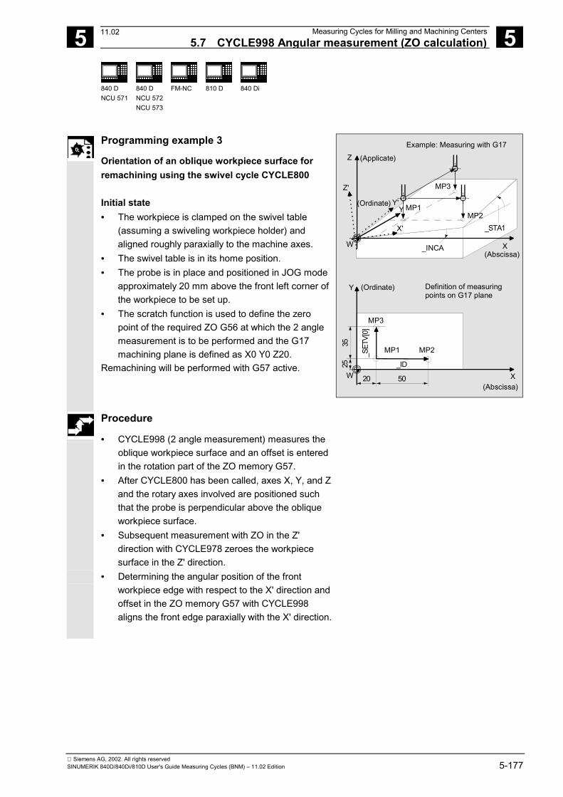
5 12.97 Measuring Cycles for Milling and Machining Centers 5.7 CYCLE998 Angular measurement (ZO calculation)
5
840 DNCU 571
840 DNCU 572NCU 573
FM-NC
810 D
840 Di
Siemens AG, 2002. All rights reservedSINUMERIK 840D/840Di/810D User's Guide Measuring Cycles (BNM) – 11.02 Edition 5-177
Programming example 3
Orientation of an oblique workpiece surface forremachining using the swivel cycle CYCLE800
Initial state• The workpiece is clamped on the swivel table
(assuming a swiveling workpiece holder) andaligned roughly paraxially to the machine axes.
• The swivel table is in its home position.• The probe is in place and positioned in JOG mode
approximately 20 mm above the front left corner ofthe workpiece to be set up.
• The scratch function is used to define the zeropoint of the required ZO G56 at which the 2 anglemeasurement is to be performed and the G17machining plane is defined as X0 Y0 Z20.
Remachining will be performed with G57 active.
Z
X
X(Abscissa)
(Applicate)
(Abscissa)
Y (Ordinate)
_ID_S
ETV[
0]
_STA1X'
Y'(Ordinate)
Z'
5020
3525
W
Y
W
Example: Measuring with G17
Definition of measuring points on G17 plane
_INCA
MP1
MP1
MP2
MP2
MP3
MP3
Procedure
• CYCLE998 (2 angle measurement) measures theoblique workpiece surface and an offset is enteredin the rotation part of the ZO memory G57.
• After CYCLE800 has been called, axes X, Y, and Zand the rotary axes involved are positioned suchthat the probe is perpendicular above the obliqueworkpiece surface.
• Subsequent measurement with ZO in the Z'direction with CYCLE978 zeroes the workpiecesurface in the Z' direction.
• Determining the angular position of the frontworkpiece edge with respect to the X' direction andoffset in the ZO memory G57 with CYCLE998aligns the front edge paraxially with the X' direction.
07.0211.02
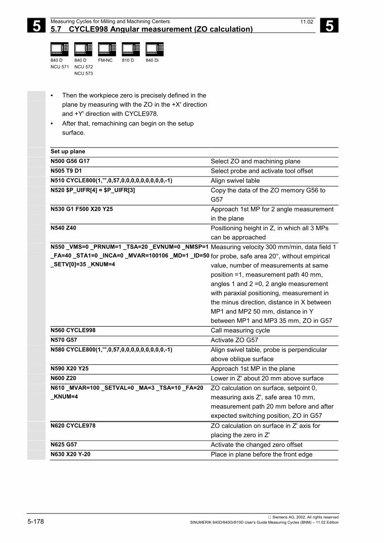
5 Measuring Cycles for Milling and Machining Centers 12.97 5.7 CYCLE998 Angular measurement (ZO calculation)
5
840 DNCU 571
840 DNCU 572NCU 573
FM-NC
810 D
840 Di
Siemens AG, 2002. All rights reserved5-178 SINUMERIK 840D/840Di/810D User's Guide Measuring Cycles (BNM) – 11.02 Edition
• Then the workpiece zero is precisely defined in theplane by measuring with the ZO in the +X' directionand +Y' direction with CYCLE978.
• After that, remachining can begin on the setupsurface.
Set up planeN500 G56 G17 Select ZO and machining planeN505 T9 D1 Select probe and activate tool offsetN510 CYCLE800(1,"",0,57,0,0,0,0,0,0,0,0,0,-1) Align swivel tableN520 $P_UIFR[4] = $P_UIFR[3] Copy the data of the ZO memory G56 to
G57N530 G1 F500 X20 Y25 Approach 1st MP for 2 angle measurement
in the planeN540 Z40 Positioning height in Z, in which all 3 MPs
can be approachedN550 _VMS=0 _PRNUM=1 _TSA=20 _EVNUM=0 _NMSP=1_FA=40 _STA1=0 _INCA=0 _MVAR=100106 _MD=1 _ID=50_SETV[0]=35 _KNUM=4
Measuring velocity 300 mm/min, data field 1for probe, safe area 20°, without empiricalvalue, number of measurements at sameposition =1, measurement path 40 mm,angles 1 and 2 =0, 2 angle measurementwith paraxial positioning, measurement inthe minus direction, distance in X betweenMP1 and MP2 50 mm, distance in Ybetween MP1 and MP3 35 mm, ZO in G57
N560 CYCLE998 Call measuring cycleN570 G57 Activate ZO G57N580 CYCLE800(1,"",0,57,0,0,0,0,0,0,0,0,0,-1) Align swivel table, probe is perpendicular
above oblique surfaceN590 X20 Y25 Approach 1st MP in the planeN600 Z20 Lower in Z' about 20 mm above surfaceN610 _MVAR=100 _SETVAL=0 _MA=3 _TSA=10 _FA=20_KNUM=4
ZO calculation on surface, setpoint 0,measuring axis Z', safe area 10 mm,measurement path 20 mm before and afterexpected switching position, ZO in G57
N620 CYCLE978 ZO calculation on surface in Z' axis forplacing the zero in Z'
N625 G57 Activate the changed zero offsetN630 X20 Y-20 Place in plane before the front edge
07.0211.02
5 12.97 Measuring Cycles for Milling and Machining Centers 5.7 CYCLE998 Angular measurement (ZO calculation)
5
840 DNCU 571
840 DNCU 572NCU 573
FM-NC
810 D
840 Di
Siemens AG, 2002. All rights reservedSINUMERIK 840D/840Di/810D User's Guide Measuring Cycles (BNM) – 11.02 Edition 5-179
N640 Z-5 Place lower in Z' direction to align the frontedge in the X' direction
N650 _MVAR=105 _MA=102 _SETVAL=0 _RA=0 _STA1=0 Angle measurement measuring axis Y',displacement in X' axis, distance betweenmeasuring points 50 mm; offset in therotation part of the ZO memory G57, setangle between edge and X' direction 0
N660 CYCLE998 Angle measurement by measuring in Y' anddisplacement between the 2 measuringpoints in X' with offset in G57
N665 G57 Activate the changed ZO G57N680 X20 Y-20N690 Z-5 Place at measuring height before the front
edgeN700 _MVAR=100 _MA=2 _SETVAL=0 _FA=10 ZO calculation on surface, measurement in
Y' direction, measurement path 10 mm infront of to 10 mm behind expected edge
N710 CYCLE978 ZO calculation on surface with measurementin +Y' direction and ZO in G57 for setting thezero in Y'
N720 G57 Activate the changed ZO G57N730 X-20 Y-20N740 Y25 Place in front of the left edgeN750 _MA=1 Measure in +X'N760 CYCLE978 ZO calculation on surface, measurement in
+X' direction, and ZO offset in G57 memory.Measurement path 10 mm in front of to 10mm behind expected edge for setting zero inX'
N770 G57 Activate the changed ZO G57N780 Z20 Raise in Z...
The oblique surface is now completely setup
N1000 M2 End of program
Comment about CYCLE800The swivel cycle CYCLE800 is used to measure andoperate on any surface by converting the activeworkpiece zero and the active tool offset to the obliquesurface in the cycle by calling the relevant NC functions,taking account of the kinematic chain of the machine,and positioning the rotary axes.
11.02
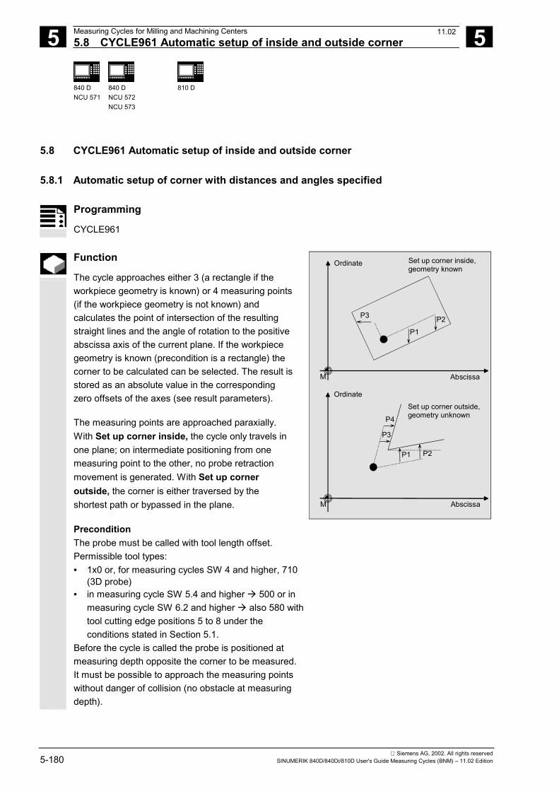
5 Measuring Cycles for Milling and Machining Centers 12.975.8 CYCLE961 Automatic setup of inside and outside corner 5
840 DNCU 571
840 DNCU 572NCU 573
810 D
Siemens AG, 2002. All rights reserved5-180 SINUMERIK 840D/840Di/810D User's Guide Measuring Cycles (BNM) – 11.02 Edition
5.8 CYCLE961 Automatic setup of inside and outside corner
5.8.1 Automatic setup of corner with distances and angles specified
Programming
CYCLE961
Function
The cycle approaches either 3 (a rectangle if theworkpiece geometry is known) or 4 measuring points(if the workpiece geometry is not known) andcalculates the point of intersection of the resultingstraight lines and the angle of rotation to the positiveabscissa axis of the current plane. If the workpiecegeometry is known (precondition is a rectangle) thecorner to be calculated can be selected. The result isstored as an absolute value in the correspondingzero offsets of the axes (see result parameters).
The measuring points are approached paraxially.With Set up corner inside, the cycle only travels inone plane; on intermediate positioning from onemeasuring point to the other, no probe retractionmovement is generated. With Set up corneroutside, the corner is either traversed by theshortest path or bypassed in the plane.
PreconditionThe probe must be called with tool length offset.Permissible tool types:• 1x0 or, for measuring cycles SW 4 and higher, 710
(3D probe)• in measuring cycle SW 5.4 and higher � 500 or in
measuring cycle SW 6.2 and higher � also 580 withtool cutting edge positions 5 to 8 under theconditions stated in Section 5.1.
Before the cycle is called the probe is positioned atmeasuring depth opposite the corner to be measured.It must be possible to approach the measuring pointswithout danger of collision (no obstacle at measuringdepth).
Ordinate
M Abscissa
Ordinate
M Abscissa
Set up corner inside,geometry known
Set up corner outside,geometry unknown
P3
P1
P2
P3
P4
P1 P2
11.02
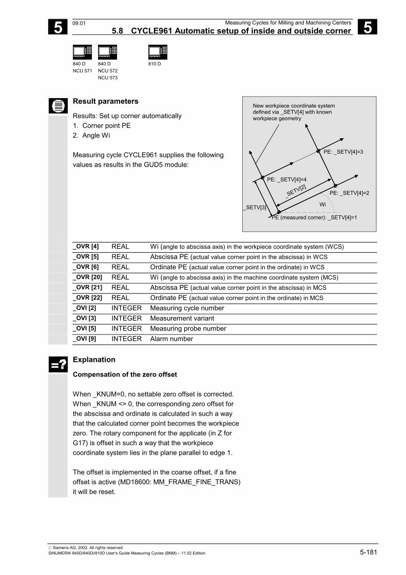
5 12.97 Measuring Cycles for Milling and Machining Centers5.8 CYCLE961 Automatic setup of inside and outside corner 5
840 DNCU 571
840 DNCU 572NCU 573
810 D
Siemens AG, 2002. All rights reservedSINUMERIK 840D/840Di/810D User's Guide Measuring Cycles (BNM) – 11.02 Edition 5-181
Result parameters
Results: Set up corner automatically1. Corner point PE2. Angle Wi
Measuring cycle CYCLE961 supplies the followingvalues as results in the GUD5 module:
PE (measured corner): _SETV[4]=1
Wi
New workpiece coordinate system defined via _SETV[4] with knownworkpiece geometry
PE: _SETV[4]=4
PE: _SETV[4]=3
PE: _SETV[4]=2
_SETV[3]
_SETV[2]
_OVR [4] REAL Wi (angle to abscissa axis) in the workpiece coordinate system (WCS)_OVR [5] REAL Abscissa PE (actual value corner point in the abscissa) in WCS_OVR [6] REAL Ordinate PE (actual value corner point in the ordinate) in WCS_OVR [20] REAL Wi (angle to abscissa axis) in the machine coordinate system (MCS)_OVR [21] REAL Abscissa PE (actual value corner point in the abscissa) in MCS_OVR [22] REAL Ordinate PE (actual value corner point in the ordinate) in MCS_OVI [2] INTEGER Measuring cycle number_OVI [3] INTEGER Measurement variant_OVI [5] INTEGER Measuring probe number_OVI [9] INTEGER Alarm number
Explanation
Compensation of the zero offset
When _KNUM=0, no settable zero offset is corrected.When _KNUM <> 0, the corresponding zero offset forthe abscissa and ordinate is calculated in such a waythat the calculated corner point becomes the workpiecezero. The rotary component for the applicate (in Z forG17) is offset in such a way that the workpiececoordinate system lies in the plane parallel to edge 1.
The offset is implemented in the coarse offset, if a fineoffset is active (MD18600: MM_FRAME_FINE_TRANS)it will be reset.
09.01
5 Measuring Cycles for Milling and Machining Centers 12.975.8 CYCLE961 Automatic setup of inside and outside corner 5
840 DNCU 571
840 DNCU 572NCU 573
810 D
Siemens AG, 2002. All rights reserved5-182 SINUMERIK 840D/840Di/810D User's Guide Measuring Cycles (BNM) – 11.02 Edition
Parameters
_MVAR 105 Set up corner inside at rectangle(geometry known, 3 measuring points)
106 Set up corner outside at rectangle(geometry known, 3 measuring points)
107 Set up corner inside(geometry unknown, 4 measuring points)
108 Set up corner outside(geometry unknown, 4 measuring points)
_FA REAL Measuring path, only included if calculated as larger thaninternal value
_KNUM 0 No automatic ZO compensation;
1...99 Autom. ZO compensationin G54...G57, G505...G599
with/without ZO compensationNo. of the zero offset in which the calculated offset andthe angle of rotation are stored
Meas. cycles≥ SW 4.42
1000 Automatic additive ZO compensation in channel-specific basic frame1)
Meas. cycles≥ SW 6.22)
1011...1026 automatic ZO compensation in 1st to 16th basic frame (channel) ($P_CHBFR[0]...$P_CHBFR[15])
2000 automatic ZO compensation in system framescratching system frame ($P_SETFR)
9999 automatic ZO compensation in an active frame settable frames G54..G57, G505...G599 or for G500
in last active basic frame according to $P_CHBFRMASK (most significant bit)
_STA1 REAL Approximate angle from positive direction of theabscissa to the 1st edge (reference edge) in MCS:
Negative value in clockwise direction;Positive direction in counterclockwise direction
_INCA REAL Angle from 1st edge to 2nd edge of the workpieceNegative value in clockwise direction;Positive value in counterclockwise direction
_ID REAL Retraction in applicate when measuring outside corner,used to overtravel the corner (when _ ID=0 the corner isbypassed) (incremental)
_SETV[0] REAL Distance between starting point and measuring point 2(positive only)
_SETV[1] REAL Distance between starting point and measuring point 4(positive only)
For measurement variants 105 and 106 only:_SETV[2] REAL Offset of origin in the abscissa (measured corner – next
corner of rectangle with an edge length 1=_SETV[2]) incounterclockwise direction
11.02
5 12.97 Measuring Cycles for Milling and Machining Centers5.8 CYCLE961 Automatic setup of inside and outside corner 5
840 DNCU 571
840 DNCU 572NCU 573
810 D
Siemens AG, 2002. All rights reservedSINUMERIK 840D/840Di/810D User's Guide Measuring Cycles (BNM) – 11.02 Edition 5-183
_SETV[3] REAL Offset of origin in the ordinate (measured corner – nextcorner of rectangle with an edge length 2=_SETV[3]) inclockwise direction
_SETV[4] REAL Specification of corner point, values 1 ... 4 (counted incounterclockwise direction)1 Measured corner2 Next corner in counterclockwise direction3 Opposite corner4 Next corner in clockwise direction
1) As of measuring cycles SW 5.3, compensation iscarried out in the last basic frame (per MD 28081:MM_NUM_BASE_FRAMES) if more than one isavailable. If measuring cycles higher than SW 5.3are used at a control with SW 4, parameter _SI[1]in the GUD 6 module must be set to 4!
2) Measuring cycles version SW 6.2 and highercan only be used with NCK-SW 6.3 and higher.
These following additional parameters are also valid:_VMS, _PRNUM and _NMSP.See Sections 2.2 and 2.3.
Procedure
Position before the cycle is calledThe probe is positioned at measuring depth oppositethe corner to be measured.The measuring points are derived from theprogrammed distance between starting point andmeasuring point 2 or measuring point 4 (measuringpoints 1 and 3 half distance). It must be possible toapproach them without collision (no obstacle atmeasuring depth). The measuring cycle generates therequired traversing blocks and performs themeasurements at the measuring points. First measuringpoint MP 2 is approached, then MP 1, MP 3, and then,depending on the parameterization, MP 4. The probetravels between MP 1 and MP 3 as a function ofparameter _ID. If _ID=0 the corner is bypassed. If_ID>0 the probe is retracted from MP 1 in the applicateby the value parameterized in _ID and then traversedvia corner MP 3.
Position after the cycle has terminatedThe probe is again positioned at the starting point (atmeasuring depth opposite the corner to be measured).
09.01
5 Measuring Cycles for Milling and Machining Centers 12.975.8 CYCLE961 Automatic setup of inside and outside corner 5
840 DNCU 571
840 DNCU 572NCU 573
810 D
Siemens AG, 2002. All rights reserved5-184 SINUMERIK 840D/840Di/810D User's Guide Measuring Cycles (BNM) – 11.02 Edition
Programming example
The coordinates of the corner of a workpiece withunknown geometry are to be determined with anoutside measurement and the zero offset G55compensated so that the corner is the workpiece zerofor active G55. The input parameters _STA1 and _INCAare estimated values. The distance to measuring points2 and 4 is 100 mm. The corner is to be bypassed. Thestarting point opposite the corner that is to be set up isreached before the measuring cycle is called. It can beapproached in operating modes Automatic or JOG.
_INCA (positive)
MP4
MP3
MP1
MP2
_STA1 (negative)
_SETV[0]
_SET[0]/2
_SET[0]/2
_SET
V[1]
_SET
V[1]
/2
_SET
V[1]
/2
ABSCISSA
ORDINATE
Start point
Approached for example in JOG mode
SETUP_CORNERN100 G17 T10 D1 Select probe
N110 _MVAR=108 _FA=20 _KNUM=2 _STA1=-35_INCA=80 _ID=30 _SETV[0]=100 _SETV[1]=100_PRNUM=1 _VMS=0 _NMSP=1
Parameterize cycle 961
N115 CYCLE961N120 M30
09.01
5 12.97 Measuring Cycles for Milling and Machining Centers5.8 CYCLE961 Automatic setup of inside and outside corner 5
840 DNCU 571
840 DNCU 572NCU 573
810 D
Siemens AG, 2002. All rights reservedSINUMERIK 840D/840Di/810D User's Guide Measuring Cycles (BNM) – 11.02 Edition 5-185
5.8.2 Automatic setup of corner by defining 4 points (measuring cycles SW 4.5 and higher)
Programming
CYCLE961
Function
Points P2, P1, P3 and P4 are approached insuccession in the cycle at positioning depth, fromwhich traversing is carried out paraxially at themeasured feedrate to the measuring depth againstthe workpiece edge.The cycle uses the relative positions of points P1 toP4 to determine the approach directions and themeasuring axis. The cycle uses the measuredresults to compute the corner points and the angle ofedge 1 (determined by measuring P2 and P1)relative to the positive abscissa axis of the currentplane and enters the coordinates of the corner pointand the angle of the relevant points of the _OVR[ ]field.
The position of points P1 and P2 relative to each otherdetermines the direction of the abscissa axis (for G17X axis) of the new coordinate system; a negative offsetof P1 and P2 in the abscissa (for G17 X axis)produces an additional 108° rotation.
PreconditionThe probe must be called with tool length offset.Permissible tool types:• 1x0 or, for measuring cycles SW 4 and higher, 710
(3D probe)• in measuring cycle SW 5.4 and higher � 500 or in
measuring cycle SW 6.2 and higher � also 580 withtool cutting edge positions 5 to 8 under theconditions stated in Section 5.1.
The probe lies at the positioning on which all 4 pointscan be approached without collision (no obstacle atpositioning depth).
Z
XW
P2
X
Y
W
P1
P4
P3
Y
X
0.0
P1P2
P3P4
Y X
(Ordinate)
(Abscissa)
_ID
F
(Applicate)
(Abscissa)
0.0
Position of points P1...P4 for measurement of an out-side corner, bottom left, or an inside corner, top right
P2
X
Y
W
P1
P4
P3
Y
X0.0
P1P2P3
P4
Y X(Ordinate)
0.0
Position of points P1...P4 for measurement of an out-side corner, top left, or an inside corner, bottom right
09.01
5 Measuring Cycles for Milling and Machining Centers 12.975.8 CYCLE961 Automatic setup of inside and outside corner 5
840 DNCU 571
840 DNCU 572NCU 573
810 D
Siemens AG, 2002. All rights reserved5-186 SINUMERIK 840D/840Di/810D User's Guide Measuring Cycles (BNM) – 11.02 Edition
Result parameters
Results: Set up corner automatically1. Corner point PE2. Angle Wi
Measuring cycle CYCLE961 supplies the followingvalues as results in the GUD5 module:
PE
Wi
New workpiece coordinate system defined via _KNUM
_OVR [4] REAL Wi (angle to abscissa axis) in the workpiece coordinate system (WCS)_OVR [5] REAL Abscissa PE (actual value corner point in the abscissa) in WCS_OVR [6] REAL Ordinate PE (actual value corner point in the ordinate) in WCS_OVR [20] REAL Wi (angle to abscissa axis) in the machine coordinate system (MCS)_OVR [21] REAL Abscissa PE (actual value corner point in the abscissa) in MCS_OVR [22] REAL Ordinate PE (actual value corner point in the ordinate) in MCS_OVI [2] INTEGER Measuring cycle number_OVI [3] INTEGER Measurement variant_OVI [5] INTEGER Measuring probe number_OVI [9] INTEGER Alarm number
Explanation
Compensation of the zero offset
When _KNUM=0, no settable zero offset is corrected.When _KNUM <> 0, the corresponding zero offset forthe abscissa and ordinate is calculated in such a waythat the calculated corner point becomes the workpiecezero. The rotary component for the applicate (in Z forG17) is offset in such a way that the workpiececoordinate system lies in the plane parallel to edge 1.
The offset is implemented in the coarse offset, if a fineoffset is active (MD18600: MM_FRAME_FINE_TRANS)it will be reset.
09.01
5 12.97 Measuring Cycles for Milling and Machining Centers5.8 CYCLE961 Automatic setup of inside and outside corner 5
840 DNCU 571
840 DNCU 572NCU 573
810 D
Siemens AG, 2002. All rights reservedSINUMERIK 840D/840Di/810D User's Guide Measuring Cycles (BNM) – 11.02 Edition 5-187
Parameters
_MVAR 117 Set up corner inside (4 measuring points)118 Set up corner outside (4 measuring points)
_FA REAL Measurement path
_KNUM REAL No. of the zero offset in which the calculated offset andthe angle of rotation are stored; (or 0)
_ID REAL Infeed of positioning depth to measuring depth(incremental)
_SETV[0] REAL Abscissa P1 in active WCS
_SETV[1] REAL Ordinate P1 in active WCS
_SETV[2] REAL Abscissa P2 in active WCS
_SETV[3] REAL Ordinate P2 in active WCS
_SETV[4] REAL Abscissa P3 in active WCS
_SETV[5] REAL Ordinate P3 in active WCS
_SETV[6] REAL Abscissa P4 in active WCS
_SETV[7] REAL Ordinate P4 in active WCS
These following additional parameters are also valid:_VMS, _PRNUM and _NMSP.
See Sections 2.2 and 2.3.
Procedure
Position before the cycle is calledThe measuring probe lies at the positioning depth.It must be possible to approach points P1 to P4 withoutdanger of collision. The measuring cycle generates thetraversing blocks and performs the measurements atthe measuring depth for points P1 to P4. Point P2 isapproached first, followed by P1, P3 and P4.
Position after the cycle has terminatedThe probe is at the positioning depth at point P4.
08.99
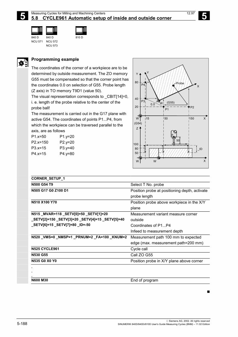
5 Measuring Cycles for Milling and Machining Centers 12.975.8 CYCLE961 Automatic setup of inside and outside corner 5
840 DNCU 571
840 DNCU 572NCU 573
810 D
Siemens AG, 2002. All rights reserved5-188 SINUMERIK 840D/840Di/810D User's Guide Measuring Cycles (BNM) – 11.02 Edition
Programming example
The coordinates of the corner of a workpiece are to bedetermined by outside measurement. The ZO memoryG55 must be compensated so that the corner point hasthe coordinates 0.0 on selection of G55. Probe length(Z axis) in TO memory T9D1 (value 50).The visual representation corresponds to _CBIT[14]=0,i. e. length of the probe relative to the center of theprobe ball!The measurement is carried out in the G17 plane withactive G54. The coordinates of points P1...P4, fromwhich the workpiece can be traversed parallel to theaxis, are as followsP1.x=50 P1.y=20P2.x=150 P2.y=20P3.x=15 P3.y=40P4.x=15 P4.y=80
_ID
F
50
Z
XWW
P2
X
Y
20
Probe
P1
P4
P340
80
15 50 150
Y
X
0.0
1008050
W
W (G55)
(G54)
CORNER_SETUP_1N500 G54 T9 Select T No. probeN505 G17 G0 Z100 D1 Position probe at positioning depth, activate
probe lengthN510 X100 Y70 Position probe above workpiece in the X/Y
planeN515 _MVAR=118 _SETV[0]=50 _SETV[1]=20_SETV[2]=150 _SETV[3]=20 _SETV[4]=15 _SETV[5]=40_SETV[6]=15 _SETV[7]=80 _ID=-50
Measurement variant measure corneroutsideCoordinates of P1...P4Infeed to measurement depth
N520 _VMS=0 _NMSP=1 _PRNUM=2 _FA=100 _KNUM=2 Measurement path 100 mm to expectededge (max. measurement path=200 mm)
N525 CYCLE961 Cycle callN530 G55 Call ZO G55N535 G0 X0 Y0 Position probe in X/Y plane above corner...N600 M30 End of program
�
6 12.97 Measuring Cycles for Turning Machines 6
Siemens AG, 2002. All rights reservedSINUMERIK 840D/840Di/810D User's Guide Measuring Cycles (BNM) – 11.02 Edition 6-189
Measuring Cycles for Turning Machines
6.1 General preconditions ................................................................................................... 6-190
6.2 CYCLE972 Tool measurement ..................................................................................... 6-1926.2.1 CYCLE972 Calibrating the tool probe ..................................................................... 6-1946.2.2 CYCLE972 Determine dimensions of calibration tools ........................................... 6-1976.2.3 CYCLE972 Measure tool......................................................................................... 6-198
6.3 CYCLE982 Tool measurement (SW 5.3 and higher).................................................... 6-2036.3.1 CYCLE982 Calibrate tool measuring probe ............................................................ 6-2086.3.2 CYCLE982 Measure tool......................................................................................... 6-2106.3.3 CYCLE982 Automatic tool measurement ............................................................... 6-2216.3.4 Incremental calibration (SW 6.2 and higher)........................................................... 6-2286.3.5 Incremental measurement (SW 6.2 and higher)..................................................... 6-2316.3.6 Milling tool: suppression of starting angle positioning with _STA1
(SW 6.2 and higher) ................................................................................................ 6-237
6.4 CYCLE973 Calibrate workpiece probe.......................................................................... 6-2386.4.1 CYCLE973 Calibrate in the reference groove (plane)............................................. 6-2406.4.2 CYCLE973 Calibrate on a random surface............................................................. 6-242
6.5 CYCLE974 Workpiece measurement ........................................................................... 6-2446.5.1 CYCLE974 Single-point measurement ZO calculation ........................................... 6-2466.5.2 CYCLE974 Single-point measurement ................................................................... 6-2496.5.3 CYCLE974 Single-point measurement with reversal .............................................. 6-253
6.6 CYCLE994 Two-point measurement ............................................................................ 6-257
6.7 Complex example for workpiece measurement............................................................ 6-262
11.02
6 Measuring Cycles for Turning Machines 12.976.1 General preconditions 6
840 DNCU 571
840 DNCU 572NCU 573
FM-NC 810 D 840 Di
Siemens AG, 2002. All rights reserved6-190 SINUMERIK 840D/840Di/810D User's Guide Measuring Cycles (BNM) – 11.02 Edition
6.1 General preconditions
Function
Measuring cycles are subroutines that have been keptgeneral for solving a certain measuring problem and whichare adapted to the specific problem by the input data.The measuring cycles are created as a program packagecomprising the actual measuring cycles and utilities.To be able to run the measuring cycles described in thisChapter, the following programs must be stored in the partprogram memory of the control.
Programming
Overview of the measuring cyclesCYCLE972 Calibrate tool probe, measure turning toolsCYCLE973 Calibrate workpiece probe in the reference groove or on any surfaceCYCLE974 Single-point measurement or ZO calculation on surface, single-point
measurement with reversalCYCLE982 Calibrate a tool probe, gauge turning and milling tools
(measuring cycles SW 5.3 and higher)CYCLE994 Two-point measurement on the diameter
Overview of the auxiliary programs requiredCYCLE100 Log ONCYCLE101 Log OFFCYCLE102 Measurement result display selectionCYCLE103 Preassignment of input dataCYCLE104 Internal subroutineCYCLE105 Generate log contents loggingCYCLE106 Logging the sequential controller loggingCYCLE107 Output of message textsCYCLE108 Output of alarmsCYCLE110 Internal subroutineCYCLE111 Internal subroutineCYCLE113 Read system date and time loggingCYCLE114 Internal subroutine (tool offset)CYCLE115 Intern subroutine (zero offset, measuring cycle SW 6.2 and higher)CYCLE117 Internal subroutine: Measuring functionsCYCLE118 Format real values logging
11.02
6 12.97 Measuring Cycles for Turning Machines6.1 General preconditions 6
840 DNCU 571
840 DNCU 572NCU 573
FM-NC 810 D 840 Di
Siemens AG, 2002. All rights reservedSINUMERIK 840D/840Di/810D User's Guide Measuring Cycles (BNM) – 11.02 Edition 6-191
The two data blocks• GUD5.DEF• GUD6.DEF are also required where all the data required by themeasuring cycles are defined.
Procedure
Call and return conditions The following general call and return conditions must beobserved:• D compensation containing the data of the calibration
tool or the workpiece probe or the tool to be measuredmust be activated before a measuring cycle is called.As the tool type for the workpiece probe, type 500 ispermissible and as of measuring cycles SW 6.2 alsotype 580 with cutting edge positions 5 to 8. With thevariants for ZO calculation, a settable zero offset mustbe active.
• No mirroring, scale factors <> 1 or coordinate rotationmust be active. As of measuring cycles SW 5.4,mirroring of workpiece measuring cycles is permissible,except for calibration (condition: MD 10610=0).
• The G functions active before the measuring cycle iscalled remain active after the measuring cycle call, evenif they have been changed inside the measuring cycle.
• Measuring cycles version SW 6.2 can only be usedwith NCK-SW 6.3 and higher.
Plane definition
The measuring cycles work internally with the 1st axis(abscissa), 2nd axis (ordinate) and 3rd axis (applicate) ofthe current plane. Which plane is the current plane is setwith G17, G18 or G19 before the measuring cycle is called.
Spindle handling
The measuring cycles have been written so that thespindle commands they contain always refer to theactive master spindle of the control. If the measuringcycles are used on machines with several spindles,the spindle with which the cycle must work must bedefined as the master spindle before the cycle iscalled.
References: /PG/ "Programming Guide, Fundamentals"
11.02
6 Measuring Cycles for Turning Machines 12.976.2 CYCLE972 Tool measurement 6
840 DNCU 571
840 DNCU 572NCU 573
FM-NC 810 D 840 Di
Siemens AG, 2002. All rights reserved6-192 SINUMERIK 840D/840Di/810D User's Guide Measuring Cycles (BNM) – 11.02 Edition
6.2 CYCLE972 Tool measurement
Programming
CYCLE972
Function
CYCLE972 performs calibration of a tool probe andmeasures tool lengths L1 and L2 for turning tools withtool edge positions 1 to 8.
Result parameters
The measuring cycle CYCLE972 returns the followingvalues in the GUD5 module for the measurementvariant calibration:
_OVR [8] REAL Trigger point in minus direction, actual value, abscissa_OVR [10] REAL Trigger point in plus direction, actual value, abscissa_OVR [12] REAL Trigger point in minus direction, actual value, ordinate_OVR [14] REAL Trigger point in plus direction, actual value, ordinate_OVR [9] REAL Trigger point in minus direction, difference, abscissa_OVR [11] REAL Trigger point in plus direction, difference, abscissa_OVR [13] REAL Trigger point in minus direction, difference, ordinate_OVR [15] REAL Trigger point in plus direction, difference, ordinate_OVR [27] REAL Zero offset area_OVR [28] REAL Safe area_OVI [2] INTEGER Measuring cycle number_OVI [3] INTEGER Measurement variant_OVI [5] INTEGER Probe number_OVI [9] INTEGER Alarm number
05.98
6 12.97 Measuring Cycles for Turning Machines6.2 CYCLE972 Tool measurement 6
840 DNCU 571
840 DNCU 572NCU 573
FM-NC 810 D 840 Di
Siemens AG, 2002. All rights reservedSINUMERIK 840D/840Di/810D User's Guide Measuring Cycles (BNM) – 11.02 Edition 6-193
Result parameters
The measuring cycle CYCLE972 returns the followingresult values in the GUD5 module after toolmeasurement:
_OVR [8] REAL Actual value length L1_OVR [9] REAL Difference length L1_OVR [10] REAL Actual value length L2_OVR [11] REAL Difference length L2_OVR [27] REAL Zero offset area_OVR [28] REAL Safe area_OVR [29] REAL Permissible dimension difference_OVR [30] REAL Empirical value_OVI [0] INTEGER D number_OVI [2] INTEGER Measuring cycle number_OVI [3] INTEGER Measurement variant_OVI [5] INTEGER Probe number_OVI [7] INTEGER Empirical value memory number_OVI [8] INTEGER T number_OVI [9] INTEGER Alarm number
Measurement variants
Measuring cycle CYCLE972 permits the followingmeasurement variants which are specified viaparameter _MVAR.
Value Meaning0 Tool probe calibration1 Tool measurement
09.01
6 Measuring Cycles for Turning Machines 12.976.2 CYCLE972 Tool measurement 6
840 DNCU 571
840 DNCU 572NCU 573
FM-NC 810 D 840 Di
Siemens AG, 2002. All rights reserved6-194 SINUMERIK 840D/840Di/810D User's Guide Measuring Cycles (BNM) – 11.02 Edition
6.2.1 CYCLE972 Calibrating the tool probe
Function
The cycle uses the calibration tool to ascertain thecurrent distance dimensions between the machinezero and the probe trigger point and automaticallyloads them into the appropriate data area in theGUD6 module. They are always calculated withoutempirical or mean values.
PreconditionThe lateral surfaces of the probe cube must bealigned parallel to the machining axes abscissa andordinate.
The approximate coordinates of the tool proberegarding the machine zero have to be entered in thedata field _TP[_PRNUM-1,0] to _TP[_PRNUM-1,3]before starting calibration. Length 1 and 2 and theradius of the calibration tool must be known exactly andstored in a tool offset data block.
This tool offset must be active when the probe is called.A turning tool must be entered as the tool type, togetherwith tool edge position 3.
Parameters
_MVAR 0 Calibration variant: Tool probe calibration_MA 1, 2 Measuring axis_PRNUM INT Probe numberThese following additional parameters are also valid:_VMS, _TZL, _TSA, _FA and _NMSP.See Sections 2.2 and 2.3.
Procedure
Position before the cycle is calledThe calibration tool must be prepositioned as shownin the figure. The measuring cycle then calculatesthe approach position itself.
08.99
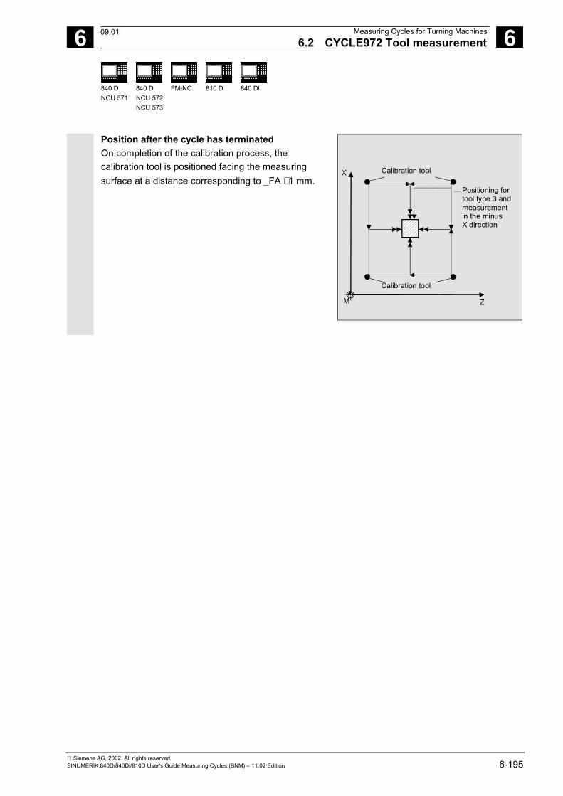
6 12.97 Measuring Cycles for Turning Machines6.2 CYCLE972 Tool measurement 6
840 DNCU 571
840 DNCU 572NCU 573
FM-NC 810 D 840 Di
Siemens AG, 2002. All rights reservedSINUMERIK 840D/840Di/810D User's Guide Measuring Cycles (BNM) – 11.02 Edition 6-195
Position after the cycle has terminatedOn completion of the calibration process, thecalibration tool is positioned facing the measuringsurface at a distance corresponding to _FA ⋅ 1 mm.
Calibration tool
Calibration tool
Positioning fortool type 3 andmeasurementin the minusX direction
X
ZM
09.01
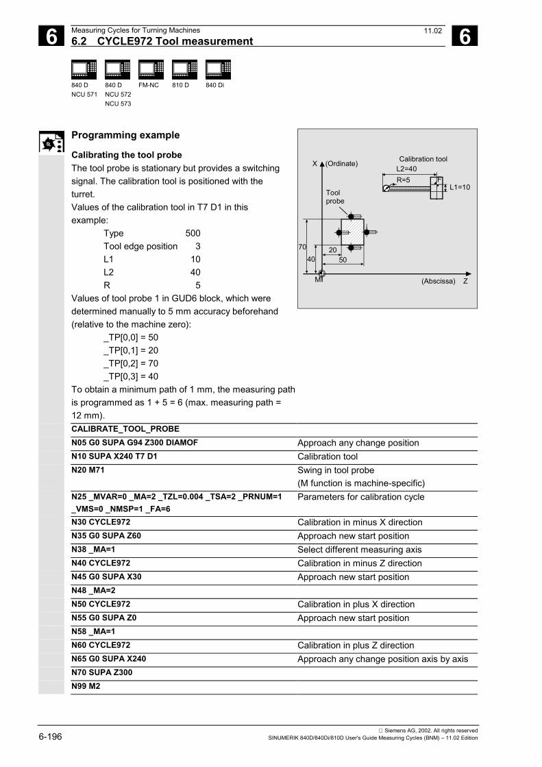
6 Measuring Cycles for Turning Machines 12.976.2 CYCLE972 Tool measurement 6
840 DNCU 571
840 DNCU 572NCU 573
FM-NC 810 D 840 Di
Siemens AG, 2002. All rights reserved6-196 SINUMERIK 840D/840Di/810D User's Guide Measuring Cycles (BNM) – 11.02 Edition
Programming example
Calibrating the tool probeThe tool probe is stationary but provides a switchingsignal. The calibration tool is positioned with theturret.Values of the calibration tool in T7 D1 in thisexample:
Type 500Tool edge position 3L1 10L2 40R 5
Values of tool probe 1 in GUD6 block, which weredetermined manually to 5 mm accuracy beforehand(relative to the machine zero):
_TP[0,0] = 50_TP[0,1] = 20_TP[0,2] = 70_TP[0,3] = 40
To obtain a minimum path of 1 mm, the measuring pathis programmed as 1 + 5 = 6 (max. measuring path =12 mm).
M
L1=10F
L2=40
4070
(Abscissa) Z
X (Ordinate) Calibration tool
Toolprobe
2050
R=5
CALIBRATE_TOOL_PROBEN05 G0 SUPA G94 Z300 DIAMOF Approach any change positionN10 SUPA X240 T7 D1 Calibration toolN20 M71 Swing in tool probe
(M function is machine-specific)N25 _MVAR=0 _MA=2 _TZL=0.004 _TSA=2 _PRNUM=1_VMS=0 _NMSP=1 _FA=6
Parameters for calibration cycle
N30 CYCLE972 Calibration in minus X directionN35 G0 SUPA Z60 Approach new start positionN38 _MA=1 Select different measuring axisN40 CYCLE972 Calibration in minus Z directionN45 G0 SUPA X30 Approach new start positionN48 _MA=2N50 CYCLE972 Calibration in plus X directionN55 G0 SUPA Z0 Approach new start positionN58 _MA=1N60 CYCLE972 Calibration in plus Z directionN65 G0 SUPA X240 Approach any change position axis by axisN70 SUPA Z300N99 M2
11.02
6 12.97 Measuring Cycles for Turning Machines6.2 CYCLE972 Tool measurement 6
840 DNCU 571
840 DNCU 572NCU 573
FM-NC 810 D 840 Di
Siemens AG, 2002. All rights reservedSINUMERIK 840D/840Di/810D User's Guide Measuring Cycles (BNM) – 11.02 Edition 6-197
6.2.2 CYCLE972 Determine dimensions of calibration tools
Function
With the following procedure it is possible todetermine the dimensions of the calibration tools:
1. Enter probe data in the GUD6 module(e.g. in parameters _TP[0,0] ... _TP[0,3] ) andspecify the calibration tool data in tool offset (e.g.T7 D1).
2. Measure the turning tool at the presettinglocation.
3. Enter the tool data in the tool offset(e.g. X60) and insert the tool into the turret.
4. Machine a test part (turn to X dimension)Set diameter: 200.000 mmActual diameter: 200.100 mm.
5. Adapt the tool offset (X59.95).6. Turn the same test part again
Set diameter: 195.000 mmActual diameter: 195.000 mm.
7. Calibrate tool probe (see sample program inSection 6.2.1).
8. Measure the tool with CYCLE972. The value59.95 (see step 5.) should be returned.
9. Change calibration tool X axis in D1Change L1 = 40 ===> to 40.95.
10. Calibrate tool probe (as for step 7.).11. Measure tool with CYCLE972. The correct value
X59.95 is then in D1. The value of the calibrationtool in X is therefore O.K.
6 Measuring Cycles for Turning Machines 12.976.2 CYCLE972 Tool measurement 6
840 DNCU 571
840 DNCU 572NCU 573
FM-NC 810 D 840 Di
Siemens AG, 2002. All rights reserved6-198 SINUMERIK 840D/840Di/810D User's Guide Measuring Cycles (BNM) – 11.02 Edition
6.2.3 CYCLE972 Measure tool
Function
The cycle calculates the new tool length and checkswhether the corrected difference from the old tool lengthis within a defined tolerance range (upper limits: safearea _TSA and dimension difference check _TDIF,lower limit: zero offset area _TZL). If this range is notviolated, the new tool length is accepted, otherwise analarm is output. Violation of the lower limit is notcorrected.Empirical values can be included as an option, meanvalue calculation is not performed.
PreconditionThe tool probe must be calibrated.The tool to be measured must be called with toollength offset.
The tool geometry data have been entered in tool offset(tool type, tool edge position, tool nose radius, length 1,length 2).
08.99
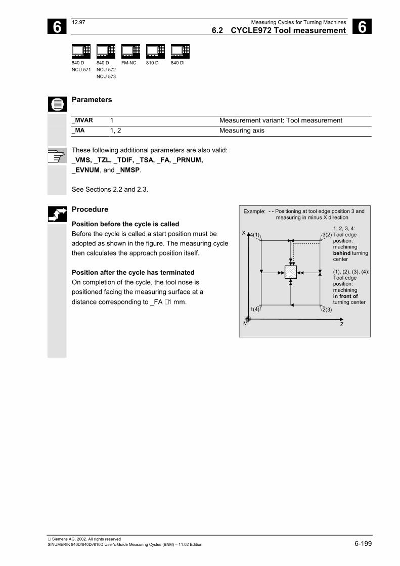
6 12.97 Measuring Cycles for Turning Machines6.2 CYCLE972 Tool measurement 6
840 DNCU 571
840 DNCU 572NCU 573
FM-NC 810 D 840 Di
Siemens AG, 2002. All rights reservedSINUMERIK 840D/840Di/810D User's Guide Measuring Cycles (BNM) – 11.02 Edition 6-199
Parameters
_MVAR 1 Measurement variant: Tool measurement_MA 1, 2 Measuring axis
These following additional parameters are also valid:_VMS, _TZL, _TDIF, _TSA, _FA, _PRNUM,_EVNUM, and _NMSP.
See Sections 2.2 and 2.3.
Procedure
Position before the cycle is calledBefore the cycle is called a start position must beadopted as shown in the figure. The measuring cyclethen calculates the approach position itself.
Position after the cycle has terminatedOn completion of the cycle, the tool nose ispositioned facing the measuring surface at adistance corresponding to _FA ⋅ 1 mm.
- - Positioning at tool edge position 3 and measuring in minus X direction
X
ZM
4(1) 3(2)
1(4) 2(3)
Example:
1, 2, 3, 4:Tool edge position:machiningbehind turningcenter
(1), (2), (3), (4):Tool edgeposition:machiningin front ofturning center
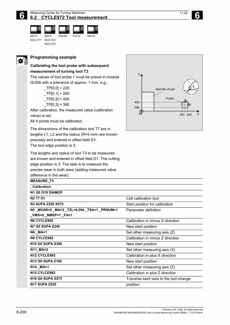
6 Measuring Cycles for Turning Machines 12.976.2 CYCLE972 Tool measurement 6
840 DNCU 571
840 DNCU 572NCU 573
FM-NC 810 D 840 Di
Siemens AG, 2002. All rights reserved6-200 SINUMERIK 840D/840Di/810D User's Guide Measuring Cycles (BNM) – 11.02 Edition
Programming example
Calibrating the tool probe with subsequentmeasurement of turning tool T3The values of tool probe 1 must be preset in moduleGUD6 with a tolerance of approx. 1 mm, e.g.:
_TP[0,0] = 220_TP[0,1] = 200_TP[0,2] = 400_TP[0,3] = 380
After calibration, the measured value (calibrationvalue) is set.All 4 points must be calibrated.
The dimensions of the calibration tool T7 are inlengths L1, L2 and the radius (R=5 mm) are knownprecisely and entered in offset field D1.The tool edge position is 3.
The lengths and radius of tool T3 to be measuredare known and entered in offset field D1. The cuttingedge position is 3. The task is to measure theprecise wear in both axes (adding measured valuedifference in the wear).
X
Z
SrP
Probe
M
Spindle chuck
220200
400
380
MEASURE_T3; Calibration:N1 G0 G18 DIAMOFN2 T7 D1 Call calibration toolN3 SUPA Z250 X575 Start position for calibrationN5 _MVAR=0 _MA=2 _TZL=0.004 _TSA=1 _PRNUM=1_VMS=0 _NMSP=1 _FA=1
Parameter definition
N6 CYCLE982 Calibration in minus X directionN7 G0 SUPA Z240 New start positionN8 _MA=1 Set other measuring axis (Z)N9 CYLCE982 Calibration in minus Z directionN10 G0 SUPA X360 New start positionN11_MA=2 Set other measuring axis (X)N12 CYCLE982 Calibration in plus X directionN13 G0 SUPA Z180 New start positionN14 _MA=1 Set other measuring axis (Z)N15 CYLCE982 Calibration in plus Z directionN16 G0 SUPA X575 Traverse each axis to the tool changeN17 SUPA Z520 position
11.02
6 12.97 Measuring Cycles for Turning Machines6.2 CYCLE972 Tool measurement 6
840 DNCU 571
840 DNCU 572NCU 573
FM-NC 810 D 840 Di
Siemens AG, 2002. All rights reservedSINUMERIK 840D/840Di/810D User's Guide Measuring Cycles (BNM) – 11.02 Edition 6-201
; Measurement:N100 T3 D1 Selection of the tool to be measuredN110 G0 SUPA Z250 X575 Start position for measurementN120 _MA=2 _TDIF=0.8 _MAVR=1 Change of parameter definition for
measurement, otherwise calibrationN130 _CHBIT[3]=1 Offset in wearN140 CYCLE982 Tool measurement in minus X direction
(L1)N150 G0 SUPA Z240 New start positionN160 _MA=1 Set other measuring axis (Z)N170 CYCLE982 Tool measurement in minus Z direction
(L2)N180 G0 SUPA X575 Retraction axis by axisN190 SUPA Z520N200 M2
Explanation
Calibrate N1 to N17:The "tip" of the calibration tool T7 is positioned inmeasuring axis X from the starting position at distance_FA=1 mm (dimension � with reference to the radius)before the probe. In axis Z, the probe tip center iscentered with respect to the probe.The measuring process is initiated in the negative Xdirection (_MA=2, starting position) with measuringvelocity 150 mm/min (_VMS=0, _FA=1). The switchingsignal is expected by the probe 1 (_PRNUM=1) within adistance of 2 ⋅ _FA=2 mm. Otherwise, an alarm will betriggered.Measurement is performed once (_NMSP=1).After successful measurement, the "tip" of T7 is _FA=1mm in front of the probe in the X direction.The calculated probe value is entered in _TP[0,2].Calibration with the measuring process has beencompleted in minus X.Calibration is then are performed in the other measuringdirections/axes.
11.02
6 Measuring Cycles for Turning Machines 12.976.2 CYCLE972 Tool measurement 6
840 DNCU 571
840 DNCU 572NCU 573
FM-NC 810 D 840 Di
Siemens AG, 2002. All rights reserved6-202 SINUMERIK 840D/840Di/810D User's Guide Measuring Cycles (BNM) – 11.02 Edition
Explanation
Measure N100 to N200:The probe has been calibrated completely.The "nose" of the turning tool T3 is positioned inmeasuring axis X from the starting position at distance_FA=1 mm (dimension � with reference to the radius) infront of the probe. In axis Z the center of the cutting edgeis centered with respect to the probe. If the cutting edgeradius =0, it is the tool nose.The measuring process is initiated in the negative Xdirection (_MA=2, starting position) with measuringvelocity 150 mm/min (_VMS=0, _FA=1). The switchingsignal is expected by the probe 1 (_PRNUM=1) within adistance of 2 ⋅ _FA=2 mm. Otherwise, an alarm will betriggered. Measurement is performed once (_NMSP=1).After successful measurement, the "nose" of T3 is _FA=1mm in front of the probe in the X direction.The calculated length difference of L1 (tool type 5xy,_MA=2, _MVAR=xx0xx1) is summated and entered in D1from T3 in the wear (_CHBIT[3]=1).Measurement and wear offset are then performed in L2 inthe minus Z direction.
Recommended parameters
The following parameters are suggested so that thisprogramming example runs reliably:• Calibration:
_TZL=0.001 Zero offset area_TSA=1 Safe area_FA=1 Multiplication factor for measuring
path• Measurement:
_TZL=0.001 Zero offset area_TSA=1 Safe area for continuous operation_FA=1 Multiplication factor for measuring
path for continuous operation_TSA=3 Safe area for setup_FA=3 Multiplication factor for measuring
path during setup_TDIF=0.3 Dimensional difference for
continuous operation_TDIF=3 Dimensional difference during
setup
11.02
6 12.97 Measuring Cycles for Turning Machines6.3 CYCLE982 Tool measurement (SW 5.3 and higher) 6
840 DNCU 571
840 DNCU 572NCU 573
FM-NC 810 D 840 Di
Siemens AG, 2002. All rights reservedSINUMERIK 840D/840Di/810D User's Guide Measuring Cycles (BNM) – 11.02 Edition 6-203
6.3 CYCLE982 Tool measurement (SW 5.3 and higher)Programming
CYCLE982
Function
Cycle CYCLE982 performs• calibration of a tool probe,• measures tool lengths L1 and L2 for turning tools
with tool edge positions 1 to 8 (function same asCYCLE972)
• for milling tools and drills on turning machines, toollengths;
• for mills, also the radiusFor measurement of mill/drill, NCK SW 5 or higher isrequired.
Supports the following measuring tasks:• Calibration as preparation for measurement/automatic
measurementThe switching positions of the probe are known roughly.Positioning of the calibration tool with respect to theprobe is performed in the cycle.It is only possible to determine the switching positionthat is in the measuring axis (_MA) and measuringdirection according to starting position. Beforebeginning measurement, all four switching positions ofthe probe must be known.
• MeasurementThe geometry of the tool to be measured is knownroughly. Positioning of the tool with respect to the probeis performed in the cycle. The geometry is to be deter-mined exactly, or the wear. Only measured values thatare in the measurement axis (_MA=) can be calculated.
• Automatic measurementThe geometry of the tool to be measured is knownroughly. Positioning of the tool with respect to the probeis performed in the cycle. The geometry is to bedetermined exactly, or the wear. All values that can bedetermined are determined automatically according totool type.
11.02
6 Measuring Cycles for Turning Machines 12.976.3 CYCLE982 Tool measurement (SW 5.3 and higher) 6
840 DNCU 571
840 DNCU 572NCU 573
FM-NC 810 D 840 Di
Siemens AG, 2002. All rights reserved6-204 SINUMERIK 840D/840Di/810D User's Guide Measuring Cycles (BNM) – 11.02 Edition
• Incremental calibration as preparation forincremental measurementThe switching positions of the probe are not known.The calibration tool must have been positioned infront of the probe manually before the cycle is called.It is only possible to determine the switching positionthat is in the measuring axis (_MA) and the statedmeasuring direction (_MD).Only the probe switching position in which the axisand direction will subsequently be measuredincrementally have to be calibrated.
• Incremental measurementThe geometry of the tool to be measured is notknown. The tool must have been positioned in frontof the probe manually before the cycle is called.The geometry is to be determined exactly. Only onemeasured value that is in the measurement axis(_MA=) can be calculated. Travel up to the probe isperformed in the cycle in the measuring axis and thestated measuring direction (_MD).
Special aspects with milling toolsThe tool length correction is specific to the turningmachine (SD:TOOL_LENGTH_TYPE=2). The lengthassignment (L1, L2) is performed like for a turning tool.Measurement is possible with a rotating (M3, M4) orwith a stationary milling spindle (M5). If the millingspindle is stationary, it is positioned at the specifiedstarting angle (_STA1) at the beginning. For simplemeasuring tasks, this positioning with _STA1 can besuppressed. If suppression is active, measurement notrequiring an SPOS-capable milling spindle is possible.To measure a second cutting edge, you can select"measurement with reversal". This involves mean valuecalculation of both measured values.
Not all functions are available in SW 5.3 and higher.Certain functions require a certain SW software versionof the measuring cycles and NCK. This information isgiven with each function.
11.02
6 12.97 Measuring Cycles for Turning Machines6.3 CYCLE982 Tool measurement (SW 5.3 and higher) 6
840 DNCU 571
840 DNCU 572NCU 573
FM-NC 810 D 840 Di
Siemens AG, 2002. All rights reservedSINUMERIK 840D/840Di/810D User's Guide Measuring Cycles (BNM) – 11.02 Edition 6-205
Result parameters
The measuring cycle CYCLE982 returns the following values inthe GUD5 module for the measurement variant calibration:_OVR [8] REAL Trigger point in minus direction, actual value, abscissa_OVR [10] REAL Trigger point in plus direction, actual value, abscissa_OVR [12] REAL Trigger point in minus direction, actual value, ordinate_OVR [14] REAL Trigger point in plus direction, actual value, ordinate_OVR [9] REAL Trigger point in minus direction, difference, abscissa_OVR [11] REAL Trigger point in plus direction, difference, abscissa_OVR [13] REAL Trigger point in minus direction, difference, ordinate_OVR [15] REAL Trigger point in plus direction, difference, ordinate_OVR [27] REAL Zero offset area_OVR [28] REAL Safe area_OVI [2] INTEGER Measuring cycle number_OVI [3] INTEGER Measurement variant_OVI [5] INTEGER Probe number_OVI [9] INTEGER Alarm number
Result parameters
The measuring cycle CYCLE982 returns the following resultvalues in the GUD5 module after tool measurement:_OVR [8] REAL Actual value length L1_OVR [9] REAL Difference length L1_OVR [10] REAL Actual value length L2_OVR [11] REAL Difference length L2_OVR [12] REAL Actual value for radius_OVR [13] REAL Difference for radius_OVR [27] REAL Zero offset area_OVR [28] REAL Safe area_OVR [29] REAL Permissible dimension difference_OVR [30] REAL Empirical value_OVI [0] INTEGER D number_OVI [2] INTEGER Measuring cycle number_OVI [3] INTEGER Measurement variant_OVI [5] INTEGER Probe number_OVI [7] INTEGER Empirical value memory_OVI [8] INTEGER T number_OVI [9] INTEGER Alarm number
06.00
6 Measuring Cycles for Turning Machines 12.976.3 CYCLE982 Tool measurement (SW 5.3 and higher) 6
840 DNCU 571
840 DNCU 572NCU 573
FM-NC 810 D 840 Di
Siemens AG, 2002. All rights reserved6-206 SINUMERIK 840D/840Di/810D User's Guide Measuring Cycles (BNM) – 11.02 Edition
Measurement variants
Measuring cycle CYCLE982 permits the followingmeasurement variants which are specified viaparameter _MVAR. _MVAR= (max. 6 decimal places)
Digit Meaning 6
5
4
3
2
1 - : No decimal point or value =0
- - - - - 0 Calibrate tool probe with calibration tool 1
Measure turning or milling tool/drill, measuring axis in _MA(specified forTurning tools: tool edge positions 1...8,Milling tools: points 3 to 5 in _MVAR)
2
Automatic measurement in abscissa and/or ordinate(specified forTurning tools: of edge positions 1...8, Milling tools: points 3 to 5 in _MVAR)
0 Fixed value (reserved for other functions) 1 Decimal place reserved – Do not use value 1 Significance for measuring milling tools only, also automatically: 0 Measuring without reversal 1 Measuring with reversal Significance for measuring milling tools only, also automatically: 0 1 Correct length only (for measuring only) 1 1 Correct radius only (for measuring only) 2 1 Correct length and radius (only for measurement, not for
incremental measurement) 3 2 Correct length and radius, travel round measuring cube opposite
starting position side (for automatic measurement only) 4 2 Correct length and radius, measuring direction for determining length
opposite to traversing direction, measuring sequence as for_MVAR=x3x02 but with different traversing motion(for automatic measurement only)
Significance for measuring milling tools only, also automatically: 0 Axial position of milling tool/drill
(Radius in ordinate, for G18: X axis, SD 42950: value =2) 1 Radial position of milling tool/drill
(Radius in abscissa, for G18: Z axis, SD 42950: value =2) 0 Measurement and calibration 1 Incremental measurement or calibration (measuring cycles SW 6.2
and higher) (restricted variants, no automatic measurement)
11.02
6 12.97 Measuring Cycles for Turning Machines6.3 CYCLE982 Tool measurement (SW 5.3 and higher) 6
840 DNCU 571
840 DNCU 572NCU 573
FM-NC 810 D 840 Di
Siemens AG, 2002. All rights reservedSINUMERIK 840D/840Di/810D User's Guide Measuring Cycles (BNM) – 11.02 Edition 6-207
• The following measurement variants are not possiblefor incremental measurement:1xxxx2; 102xx1; 112xx1
• The following measurement variants are permitted if_CHBIT[20]=1 (suppression of the starting angleposition with _STA1) on a milling tool:xxx001 (with x: 0 or 1, no other values)
• A measurement variant can also be impermissible ifit cannot be performed with the stated measuringaxis _MA, e.g.: The miller radius must bedetermined. However, with this position of the millerit is not in the measuring axis.
11.02
6 Measuring Cycles for Turning Machines 12.976.3 CYCLE982 Tool measurement (SW 5.3 and higher) 6
840 DNCU 571
840 DNCU 572NCU 573
FM-NC 810 D 840 Di
Siemens AG, 2002. All rights reserved6-208 SINUMERIK 840D/840Di/810D User's Guide Measuring Cycles (BNM) – 11.02 Edition
6.3.1 CYCLE982 Calibrate tool measuring probe
Function (as described in CYCLE972)
The cycle uses the calibration tool to ascertain thecurrent distance dimensions between the machine zeroand the probe trigger point and automatically loadsthem into the appropriate data area in the GUD6module. They are always calculated without empirical ormean values.
PreconditionThe lateral surfaces of the probe cube must bealigned parallel to the machining axes abscissa andordinate.
The approximate coordinates of the tool probe withrespect to the machine zero have to be entered in thedata field _TP[_PRNUM-1,0] to _TP[_PRNUM-1,3] inblock GUD6 before starting calibration. Length 1 and 2and the radius of the calibration tool must be stored in atool offset data block.
This tool offset must be active when the probe is called.A turning tool must be specified as the tool type. Thetool edge positions must be 3.
Parameters
_MVAR 0 Calibration variant: Tool probe calibration_MA 1, 2 Measuring axis_PRNUM INT Probe numberThese following additional parameters are also valid:_VMS, _TZL, _TSA, _FA and _NMSP.See Sections 2.2 and 2.3.
06.00
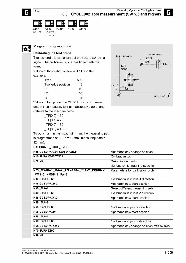
6 12.97 Measuring Cycles for Turning Machines6.3 CYCLE982 Tool measurement (SW 5.3 and higher) 6
840 DNCU 571
840 DNCU 572NCU 573
FM-NC 810 D 840 Di
Siemens AG, 2002. All rights reservedSINUMERIK 840D/840Di/810D User's Guide Measuring Cycles (BNM) – 11.02 Edition 6-209
Programming example
Calibrating the tool probeThe tool probe is stationary but provides a switchingsignal. The calibration tool is positioned with theturret.Values of the calibration tool in T7 D1 in thisexample:
Type 500Tool edge position 3L1 10L2 40R 5
Values of tool probe 1 in GUD6 block, which weredetermined manually to 5 mm accuracy beforehand(relative to the machine zero):
_TP[0,0] = 50_TP[0,1] = 20_TP[0,2] = 70_TP[0,3] = 40
To obtain a minimum path of 1 mm, the measuring pathis programmed as 1 + 5 = 6 (max. measuring path =12 mm).
M
L1=10F
L2=40
4070
(Abscissa) Z
X (Ordinate) Calibration tool
Toolprobe
2050
R=5
CALIBRATE_TOOL_PROBEN05 G0 SUPA G94 Z300 DIAMOF Approach any change positionN10 SUPA X240 T7 D1 Calibration toolN20 M71 Swing in tool probe
(M function is machine-specific)N25 _MVAR=0 _MA=2 _TZL=0.004 _TSA=2 _PRNUM=1_VMS=0 _NMSP=1 _FA=6
Parameters for calibration cycle
N30 CYCLE982 Calibration in minus X directionN35 G0 SUPA Z60 Approach new start positionN38 _MA=1 Select different measuring axisN40 CYCLE982 Calibration in minus Z directionN45 G0 SUPA X30 Approach new start positionN48 _MA=2N50 CYCLE982 Calibration in plus X directionN55 G0 SUPA Z0 Approach new start positionN58 _MA=1N60 CYCLE982 Calibration in plus Z directionN65 G0 SUPA X240 Approach any change position axis by axisN70 SUPA Z300N99 M2
11.02
6 Measuring Cycles for Turning Machines 12.976.3 CYCLE982 Tool measurement (SW 5.3 and higher) 6
840 DNCU 571
840 DNCU 572NCU 573
FM-NC 810 D 840 Di
Siemens AG, 2002. All rights reserved6-210 SINUMERIK 840D/840Di/810D User's Guide Measuring Cycles (BNM) – 11.02 Edition
6.3.2 CYCLE982 Measure tool
Function
The cycle calculates the new tool length and checks whetherthe corrected difference from the old tool length is within adefined tolerance range (upper limits: safe area _TSA anddimension difference check _TDIF, lower limit: zero offsetarea _TZL). If this range is not violated, the new tool length isaccepted, otherwise an alarm is output. Violation of the lowerlimit is not corrected.Empirical values are included if selected (with the value of_EVNUM).The lengths of turning tools (type 5xy) or milling tools/drills(type 1xy / 2xy) can be measured on lathes. In the case ofmilling tools, the tool radius offset can also be measured.With milling tools, the measurement is further specified withthe 3rd to 5th decimal places of parameter _MVAR.The calculated offsets are entered in the active D number.Whether the offset is entered in the geometry data thusdeleting the wear data (first measurement) or whether theentry is made in the wear data (remeasurement), depends onthe position of measurement bit _CHBIT[3].The offset values in the measurement axis (_MA=) can becalculated.If _CHBIT[20]=1, positioning of the milling spindle at the valueof _STA1 can be suppressed.That is possible with the following miller measurementvariants:_MVAR=xxx001 (with x: 0 or 1, no other values)General preconditionsThe tool probe must be calibrated completely.The tool to be measured must be called with tool length offset(D number).The tool geometry data in tool offset have been entered (tooltype, tool edge position, tool nose radius/cutter radius,length 1, length 2).
06.00
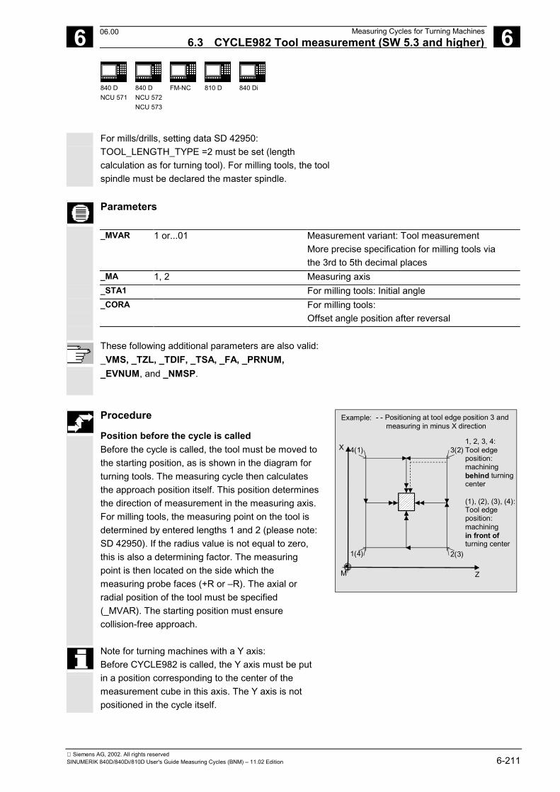
6 12.97 Measuring Cycles for Turning Machines6.3 CYCLE982 Tool measurement (SW 5.3 and higher) 6
840 DNCU 571
840 DNCU 572NCU 573
FM-NC 810 D 840 Di
Siemens AG, 2002. All rights reservedSINUMERIK 840D/840Di/810D User's Guide Measuring Cycles (BNM) – 11.02 Edition 6-211
For mills/drills, setting data SD 42950:TOOL_LENGTH_TYPE =2 must be set (lengthcalculation as for turning tool). For milling tools, the toolspindle must be declared the master spindle.
Parameters
_MVAR 1 or...01 Measurement variant: Tool measurementMore precise specification for milling tools viathe 3rd to 5th decimal places
_MA 1, 2 Measuring axis_STA1 For milling tools: Initial angle_CORA For milling tools:
Offset angle position after reversal
These following additional parameters are also valid:_VMS, _TZL, _TDIF, _TSA, _FA, _PRNUM,_EVNUM, and _NMSP.
Procedure
Position before the cycle is calledBefore the cycle is called, the tool must be moved tothe starting position, as is shown in the diagram forturning tools. The measuring cycle then calculatesthe approach position itself. This position determinesthe direction of measurement in the measuring axis.For milling tools, the measuring point on the tool isdetermined by entered lengths 1 and 2 (please note:SD 42950). If the radius value is not equal to zero,this is also a determining factor. The measuringpoint is then located on the side which themeasuring probe faces (+R or –R). The axial orradial position of the tool must be specified(_MVAR). The starting position must ensurecollision-free approach.
- - Positioning at tool edge position 3 and measuring in minus X direction
X
ZM
4(1) 3(2)
1(4) 2(3)
Example:
1, 2, 3, 4:Tool edge position:machiningbehind turningcenter
(1), (2), (3), (4):Tool edgeposition:machiningin front ofturning center
Note for turning machines with a Y axis:Before CYCLE982 is called, the Y axis must be putin a position corresponding to the center of themeasurement cube in this axis. The Y axis is notpositioned in the cycle itself.
06.00
6 Measuring Cycles for Turning Machines 12.976.3 CYCLE982 Tool measurement (SW 5.3 and higher) 6
840 DNCU 571
840 DNCU 572NCU 573
FM-NC 810 D 840 Di
Siemens AG, 2002. All rights reserved6-212 SINUMERIK 840D/840Di/810D User's Guide Measuring Cycles (BNM) – 11.02 Edition
In the case of milling tools, length and radius can beselected as an alternative to length only to determinethe cutter radius.
For length and radius, two measuring points arerequired. These are approached from different sides ofthe measuring probe. First the measuring point facingthe measuring probe at the starting point is approached.Then, after travel round the probe (in the direction of thestarting point), the 2nd measuring point is measured inthe opposite direction. If the spindle is stationary (M5)and measurement without reversal is selected, the2nd measurement is performed with a spindle rotationof 180 degrees. The same cutting edge used for the 1stmeasurement is now used.The L1 or L2 offset values and the cutter radius arecalculated from these two measurements.
Measurement with reversal can be selected separatelywith _MVAR:First the measuring point is measured in the selectedaxis and in a milling spindle position according tostarting angle _STA1. Then the tool (spindle) is turned180 degrees and measured again. The average value isthe measured value.Measurement with reversal causes a secondmeasurement at each measuring point P with a spindlerotation through 180 degrees from the starting angle.The offset angle entered in _CORA is summated tothese 180 degrees. That enables selection of a certain2nd milling cutting edge that is offset from the 1stcutting edge by precisely 180 degrees. Measurementwith reversal permits measurement of two cutting edgesof one tool. The mean value is the offset value.
If _CHBIT[20]=1, selected measurement variants arepossible for a milling cutter without taking the startingangle _STA1 into account.
11.02
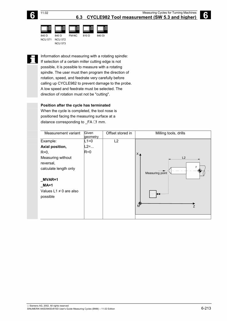
6 12.97 Measuring Cycles for Turning Machines6.3 CYCLE982 Tool measurement (SW 5.3 and higher) 6
840 DNCU 571
840 DNCU 572NCU 573
FM-NC 810 D 840 Di
Siemens AG, 2002. All rights reservedSINUMERIK 840D/840Di/810D User's Guide Measuring Cycles (BNM) – 11.02 Edition 6-213
Information about measuring with a rotating spindle:If selection of a certain miller cutting edge is notpossible, it is possible to measure with a rotatingspindle. The user must then program the direction ofrotation, speed, and feedrate very carefully beforecalling up CYCLE982 to prevent damage to the probe.A low speed and feedrate must be selected. Thedirection of rotation must not be "cutting".
Position after the cycle has terminatedWhen the cycle is completed, the tool nose ispositioned facing the measuring surface at adistance corresponding to _FA ⋅ 1 mm.
Measurement variant Givengeometry
Offset stored in Milling tools, drills
Example:Axial position,R=0,Measuring withoutreversal,calculate length only
_MVAR=1_MA=1Values L1 ≠ 0 are alsopossible
L1=0L2=...R=0
L2
X
ZM
F
L2
Measuring point
F
11.02
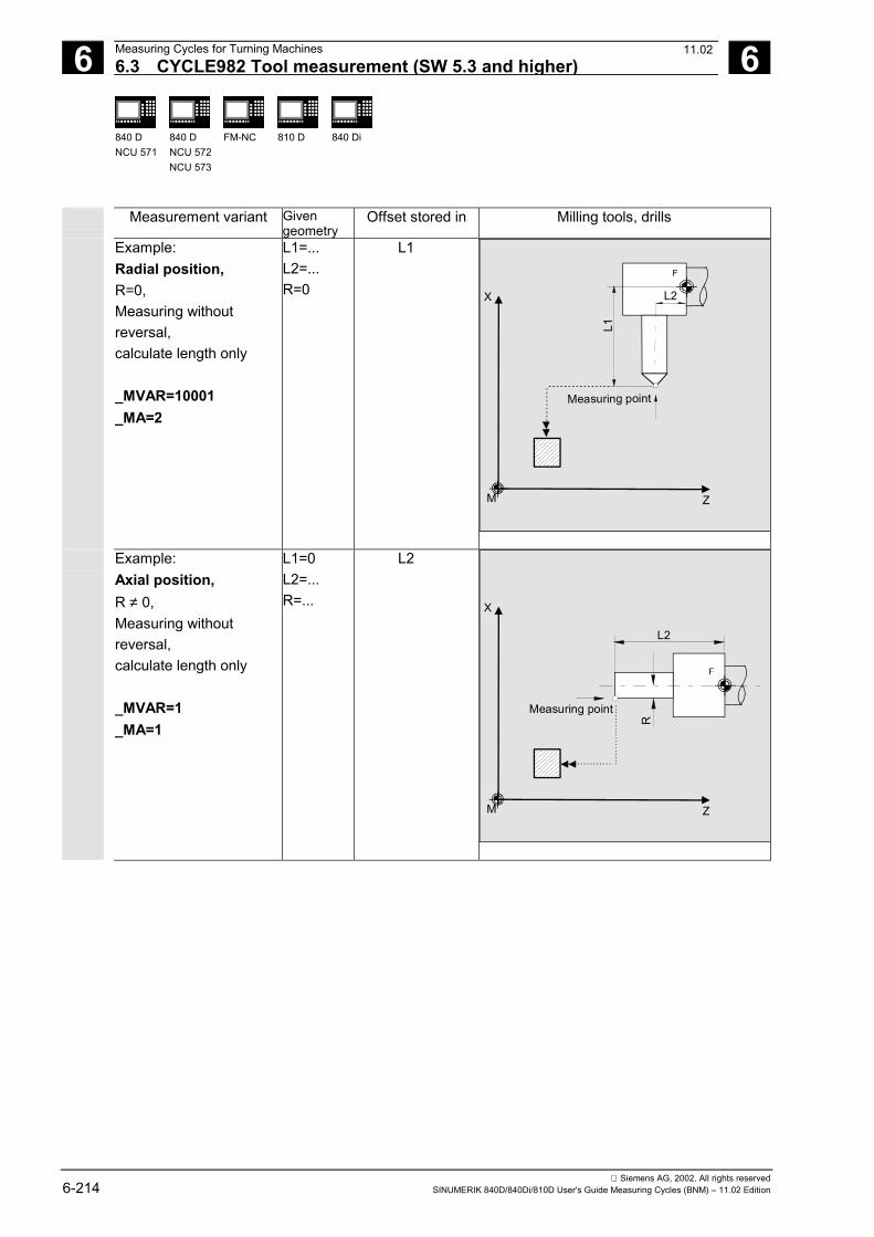
6 Measuring Cycles for Turning Machines 12.976.3 CYCLE982 Tool measurement (SW 5.3 and higher) 6
840 DNCU 571
840 DNCU 572NCU 573
FM-NC 810 D 840 Di
Siemens AG, 2002. All rights reserved6-214 SINUMERIK 840D/840Di/810D User's Guide Measuring Cycles (BNM) – 11.02 Edition
Measurement variant Givengeometry
Offset stored in Milling tools, drills
Example:Radial position,R=0,Measuring withoutreversal,calculate length only
_MVAR=10001_MA=2
L1=...L2=...R=0
L1
X
ZM
L2
F
L1
Measuring point
F
Example:Axial position,R ≠ 0,Measuring withoutreversal,calculate length only
_MVAR=1_MA=1
L1=0L2=...R=...
L2
X
ZM
FF
L2R
Measuring point
11.02
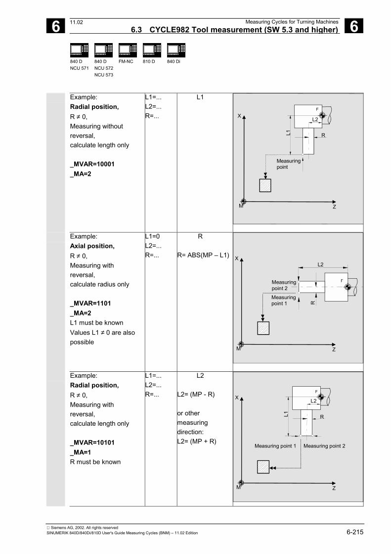
6 12.97 Measuring Cycles for Turning Machines6.3 CYCLE982 Tool measurement (SW 5.3 and higher) 6
840 DNCU 571
840 DNCU 572NCU 573
FM-NC 810 D 840 Di
Siemens AG, 2002. All rights reservedSINUMERIK 840D/840Di/810D User's Guide Measuring Cycles (BNM) – 11.02 Edition 6-215
Example:Radial position,R ≠ 0,Measuring withoutreversal,calculate length only
_MVAR=10001_MA=2
L1=...L2=...R=...
L1
X
ZM
L2
F
L1 R
Measuring point
F
Example:Axial position,R ≠ 0,Measuring withreversal,calculate radius only
_MVAR=1101_MA=2L1 must be knownValues L1 ≠ 0 are alsopossible
L1=0L2=...R=...
R
R= ABS(MP – L1) X
ZM
FF
L2
R
Measuring point 1
Measuring point 2
Example:Radial position,R ≠ 0,Measuring withreversal,calculate length only
_MVAR=10101_MA=1R must be known
L1=...L2=...R=...
L2
L2= (MP - R)
or othermeasuringdirection:L2= (MP + R)
X
ZM
L2
FF
L1 R
Measuring point 1 Measuring point 2
11.02
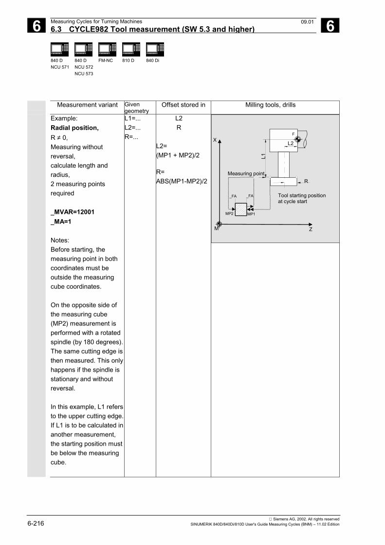
6 Measuring Cycles for Turning Machines 12.976.3 CYCLE982 Tool measurement (SW 5.3 and higher) 6
840 DNCU 571
840 DNCU 572NCU 573
FM-NC 810 D 840 Di
Siemens AG, 2002. All rights reserved6-216 SINUMERIK 840D/840Di/810D User's Guide Measuring Cycles (BNM) – 11.02 Edition
Measurement variant Givengeometry
Offset stored in Milling tools, drills
Example:Radial position,R ≠ 0,Measuring withoutreversal,calculate length andradius,2 measuring pointsrequired
_MVAR=12001_MA=1
Notes:Before starting, themeasuring point in bothcoordinates must beoutside the measuringcube coordinates.
On the opposite side ofthe measuring cube(MP2) measurement isperformed with a rotatedspindle (by 180 degrees).The same cutting edge isthen measured. This onlyhappens if the spindle isstationary and withoutreversal.
In this example, L1 refersto the upper cutting edge.If L1 is to be calculated inanother measurement,the starting position mustbe below the measuringcube.
L1=...L2=...R=...
L2R
L2=(MP1 + MP2)/2
R=ABS(MP1-MP2)/2
X
ZM
L2
FF
L1
R
MP1MP2
_FA _FA Tool starting positionat cycle start
Measuring point
09.01
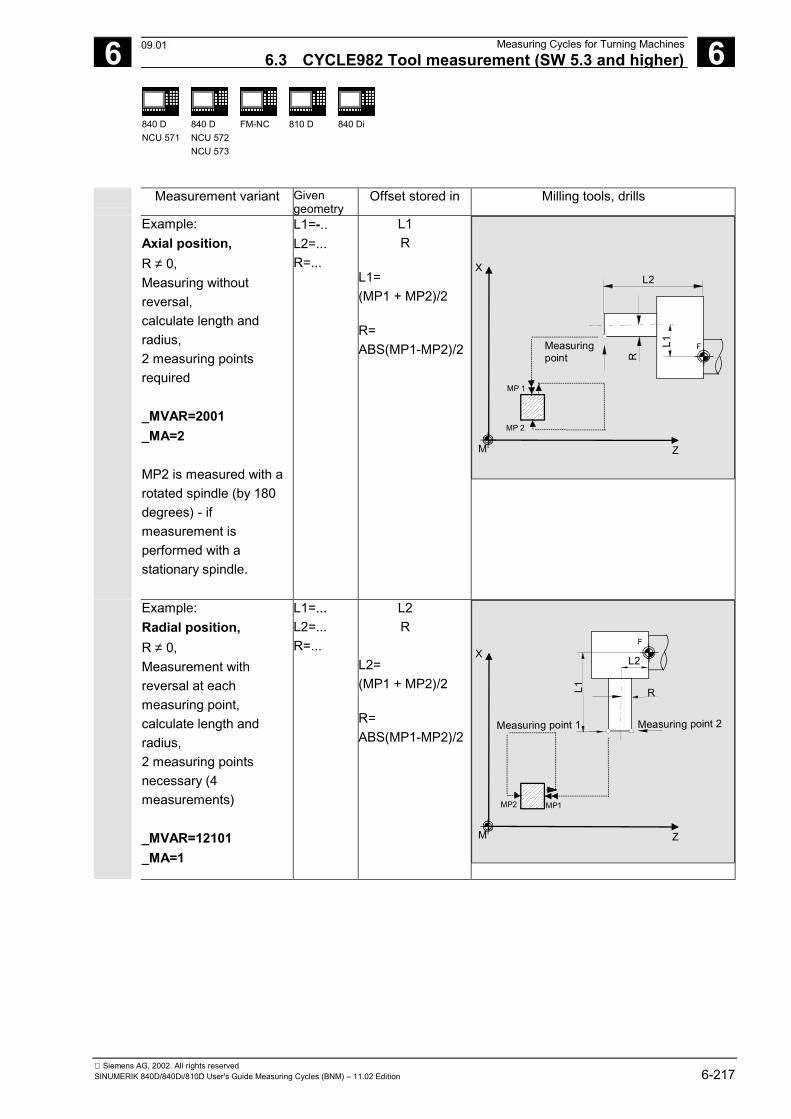
6 12.97 Measuring Cycles for Turning Machines6.3 CYCLE982 Tool measurement (SW 5.3 and higher) 6
840 DNCU 571
840 DNCU 572NCU 573
FM-NC 810 D 840 Di
Siemens AG, 2002. All rights reservedSINUMERIK 840D/840Di/810D User's Guide Measuring Cycles (BNM) – 11.02 Edition 6-217
Measurement variant Givengeometry
Offset stored in Milling tools, drills
Example:Axial position,R ≠ 0,Measuring withoutreversal,calculate length andradius,2 measuring pointsrequired
_MVAR=2001_MA=2
MP2 is measured with arotated spindle (by 180degrees) - ifmeasurement isperformed with astationary spindle.
L1=-..L2=...R=...
L1R
L1=(MP1 + MP2)/2
R=ABS(MP1-MP2)/2
X
ZM
FL1
L2
R
Measuringpoint
MP 1
MP 2
Example:Radial position,R ≠ 0,Measurement withreversal at eachmeasuring point,calculate length andradius,2 measuring pointsnecessary (4measurements)
_MVAR=12101_MA=1
L1=...L2=...R=...
L2R
L2=(MP1 + MP2)/2
R=ABS(MP1-MP2)/2
X
ZM
L2
FF
L1 R
Measuring point 1 Measuring point 2
MP1MP2
09.01
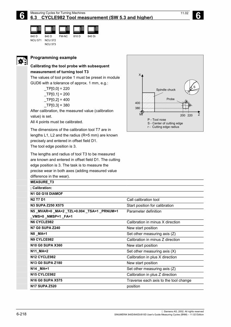
6 Measuring Cycles for Turning Machines 12.976.3 CYCLE982 Tool measurement (SW 5.3 and higher) 6
840 DNCU 571
840 DNCU 572NCU 573
FM-NC 810 D 840 Di
Siemens AG, 2002. All rights reserved6-218 SINUMERIK 840D/840Di/810D User's Guide Measuring Cycles (BNM) – 11.02 Edition
Programming example
Calibrating the tool probe with subsequentmeasurement of turning tool T3The values of tool probe 1 must be preset in moduleGUD6 with a tolerance of approx. 1 mm, e.g.:
_TP[0,0] = 220_TP[0,1] = 200_TP[0,2] = 400_TP[0,3] = 380
After calibration, the measured value (calibrationvalue) is set.All 4 points must be calibrated.
The dimensions of the calibration tool T7 are inlengths L1, L2 and the radius (R=5 mm) are knownprecisely and entered in offset field D1.The tool edge position is 3.
The lengths and radius of tool T3 to be measuredare known and entered in offset field D1. The cuttingedge position is 3. The task is to measure theprecise wear in both axes (adding measured valuedifference in the wear).
X
Z
SrP
Probe
M
Spindle chuck
220200
400380
P - Tool noseS - Center of cutting edger - Cutting edge radius
MEASURE_T3; Calibration:N1 G0 G18 DIAMOFN2 T7 D1 Call calibration toolN3 SUPA Z250 X575 Start position for calibrationN5 _MVAR=0 _MA=2 _TZL=0.004 _TSA=1 _PRNUM=1_VMS=0 _NMSP=1 _FA=1
Parameter definition
N6 CYCLE982 Calibration in minus X directionN7 G0 SUPA Z240 New start positionN8 _MA=1 Set other measuring axis (Z)N9 CYLCE982 Calibration in minus Z directionN10 G0 SUPA X360 New start positionN11_MA=2 Set other measuring axis (X)N12 CYCLE982 Calibration in plus X directionN13 G0 SUPA Z180 New start positionN14 _MA=1 Set other measuring axis (Z)N15 CYLCE982 Calibration in plus Z directionN16 G0 SUPA X575 Traverse each axis to the tool changeN17 SUPA Z520 position
11.02
6 12.97 Measuring Cycles for Turning Machines6.3 CYCLE982 Tool measurement (SW 5.3 and higher) 6
840 DNCU 571
840 DNCU 572NCU 573
FM-NC 810 D 840 Di
Siemens AG, 2002. All rights reservedSINUMERIK 840D/840Di/810D User's Guide Measuring Cycles (BNM) – 11.02 Edition 6-219
; Measurement:N100 T3 D1 Selection of the tool to be measuredN110 G0 SUPA Z250 X575 Start position for measurementN120 _MA=2 _TDIF=0.8 _MAVR=1 Change of parameter definition for
measurement, otherwise calibrationN130 _CHBIT[3]=1 Offset in wearN140 CYCLE982 Tool measurement in minus X direction
(L1)N150 G0 SUPA Z240 New start positionN160 _MA=1 Set other measuring axis (Z)N170 CYCLE982 Tool measurement in minus Z direction
(L2)N180 G0 SUPA X575 Retraction axis by axisN190 SUPA Z520N200 M2
Explanation
Calibrate N1 to N17:The "tip" of the calibration tool T7 is positioned inmeasuring axis X from the starting position at distance_FA=1 mm (dimension � with reference to the radius)before the probe. In axis Z, the probe tip center iscentered with respect to the probe.The measuring process is initiated in the negative Xdirection (_MA=2, starting position) with measuringvelocity 150 mm/min (_VMS=0, _FA=1). The switchingsignal is expected by the probe 1 (_PRNUM=1) within adistance of 2 ⋅ _FA=2 mm. Otherwise, an alarm will betriggered.Measurement is performed once (_NMSP=1).After successful measurement, the "tip" of T7 is_FA=1 mm in front of the probe in the X direction.The calculated probe value is entered in _TP[0,2].Calibration with the measuring process has beencompleted in minus X.Calibration is then performed in the other measuringdirections/axes.
11.02
6 Measuring Cycles for Turning Machines 12.976.3 CYCLE982 Tool measurement (SW 5.3 and higher) 6
840 DNCU 571
840 DNCU 572NCU 573
FM-NC 810 D 840 Di
Siemens AG, 2002. All rights reserved6-220 SINUMERIK 840D/840Di/810D User's Guide Measuring Cycles (BNM) – 11.02 Edition
Explanation
Measure N100 to N200:The probe has been calibrated completely.The "nose" of the turning tool T3 is positioned inmeasuring axis X from the starting position at distance_FA=1 mm (dimension � with reference to the radius)in front of the probe. In axis Z the center of the cuttingedge is centered with respect to the probe. If the cuttingedge radius =0, it is the tool nose.The measuring process is initiated in the negative Xdirection (_MA=2, starting position) with measuringvelocity 150 mm/min (_VMS=0, _FA=1). The switchingsignal is expected by the probe 1 (_PRNUM=1) within adistance of 2 ⋅ _FA=2 mm. Otherwise, an alarm will betriggered. Measurement is performed once (_NMSP=1).After successful measurement, the "nose" of T3 is_FA=1 mm in front of the probe in the X direction.The calculated length difference of L1 (tool type 5xy,_MA=2, _MVAR=xx0xx1) is summated and entered inD1 from T3 in the wear (_CHBIT[3]=1).Measurement and wear offset are then performed in L2in the minus Z direction.
Recommended parameters
The following parameters are suggested so that thisprogramming example runs reliably:
• Calibration:_TZL = 0.001 zero offset range_TSA = 1 safe area
• Measurement:
_TZL = 0.001 zero offset range_TSA = 1 safe area during continuous
operation_TSA = 3 safe area during setup_TDIF = 0.3 dimensional difference check
during continuous operation_TDIF = 3 dimensional difference check
during setup
11.02
6 12.97 Measuring Cycles for Turning Machines6.3 CYCLE982 Tool measurement (SW 5.3 and higher) 6
840 DNCU 571
840 DNCU 572NCU 573
FM-NC 810 D 840 Di
Siemens AG, 2002. All rights reservedSINUMERIK 840D/840Di/810D User's Guide Measuring Cycles (BNM) – 11.02 Edition 6-221
6.3.3 CYCLE982 Automatic tool measurement
Function
Function as for – non-automatic measurement
Relevant information:In the case of turning tools, both lengths are calculated.(for tool edge positions 5, 6, 7 and 8, only one length.With milling tools/drills, the measurement is furtherspecified with the 3rd to 5th decimal places ofparameter _MVAR.The measuring cycle generates the approach blocks tothe measuring probe and the traversing movement formeasurement from length 1, length 2, and the radiusitself. Prerequisite is a correctly selected startingposition.
In automatic measurement, the offsets to be calculatedare defined by the tool type.• Turning tool: Both lengths (2 measurements)• Drill: Length according to axial or radial
position (1 measurement)• Mill: Both lengths and radius (4 measurements),
if the radius is R=0, both lengths only arecalculated (2 measurements).
The calculated offsets are entered in the active Dnumber. Whether the offset is entered in the geometrydata thus deleting the wear data (first measurement) orwhether the entry is made in the wear data (remeasure-ment), depends on the position of measurement bit_CHBIT[3].
PreconditionNon-automatic – as for tool measurement
06.00
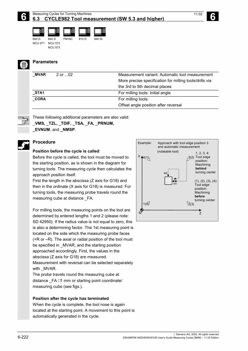
6 Measuring Cycles for Turning Machines 12.976.3 CYCLE982 Tool measurement (SW 5.3 and higher) 6
840 DNCU 571
840 DNCU 572NCU 573
FM-NC 810 D 840 Di
Siemens AG, 2002. All rights reserved6-222 SINUMERIK 840D/840Di/810D User's Guide Measuring Cycles (BNM) – 11.02 Edition
Parameters
_MVAR 2 or ...02 Measurement variant: Automatic tool measurementMore precise specification for milling tools/drills viathe 3rd to 5th decimal places
_STA1 For milling tools: Initial angle_CORA For milling tools:
Offset angle position after reversal
These following additional parameters are also valid:_VMS, _TZL, _TDIF, _TSA, _FA, _PRNUM,_EVNUM, and _NMSP.
Procedure
Position before the cycle is calledBefore the cycle is called, the tool must be moved tothe starting position, as is shown in the diagram forturning tools. The measuring cycle then calculates theapproach position itself.First the length in the abscissa (Z axis for G18) andthen in the ordinate (X axis for G18) is measured. Forturning tools, the measuring probe travels round themeasuring cube at distance _FA.
For milling tools, the measuring points on the tool aredetermined by entered lengths 1 and 2 (please note:SD 42950). If the radius value is not equal to zero, thisis also a determining factor. The 1st measuring point islocated on the side which the measuring probe faces(+R or –R). The axial or radial position of the tool mustbe specified in _MVAR, and the starting positionapproached accordingly. First, the values in theabscissa (Z axis for G18) are measured.Measurement with reversal can be selected separatelywith _MVAR.The probe travels round the measuring cube atdistance _FA ⋅ 1 mm or starting point coordinate/measuring cube (see figs.).
Position after the cycle has terminatedWhen the cycle is complete, the tool nose is againlocated at the starting point. A movement to this point isautomatically generated in the cycle.
Approach with tool edge position 3 and automatic measurement
X
ZM
4(1) 3(2)
1(4) 2(3)
Example:
1, 2, 3, 4:Tool edgeposition:Machiningbehindturning center
(1), (2), (3), (4):Tool edgeposition:Machining beforeturning center
(rotatable tool)
M1
M2
11.02
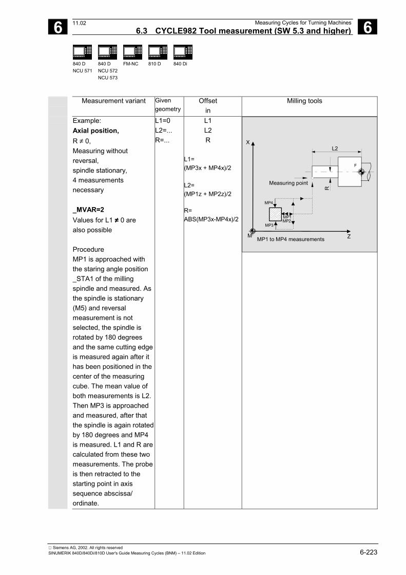
6 12.97 Measuring Cycles for Turning Machines6.3 CYCLE982 Tool measurement (SW 5.3 and higher) 6
840 DNCU 571
840 DNCU 572NCU 573
FM-NC 810 D 840 Di
Siemens AG, 2002. All rights reservedSINUMERIK 840D/840Di/810D User's Guide Measuring Cycles (BNM) – 11.02 Edition 6-223
Measurement variant Givengeometry
Offsetin
Milling tools
Example:Axial position,R ≠ 0,Measuring withoutreversal,spindle stationary,4 measurementsnecessary
_MVAR=2Values for L1 ≠≠≠≠ 0 arealso possible
ProcedureMP1 is approached withthe staring angle position_STA1 of the millingspindle and measured. Asthe spindle is stationary(M5) and reversalmeasurement is notselected, the spindle isrotated by 180 degreesand the same cutting edgeis measured again after ithas been positioned in thecenter of the measuringcube. The mean value ofboth measurements is L2.Then MP3 is approachedand measured, after thatthe spindle is again rotatedby 180 degrees and MP4is measured. L1 and R arecalculated from these twomeasurements. The probeis then retracted to thestarting point in axissequence abscissa/ordinate.
L1=0L2=...R=...
L1L2R
L1=(MP3x + MP4x)/2
L2=(MP1z + MP2z)/2
R=ABS(MP3x-MP4x)/2
X
ZM
FF
L2
R
Measuring point
MP1
MP4
MP3MP2
MP1 to MP4 measurements
11.02
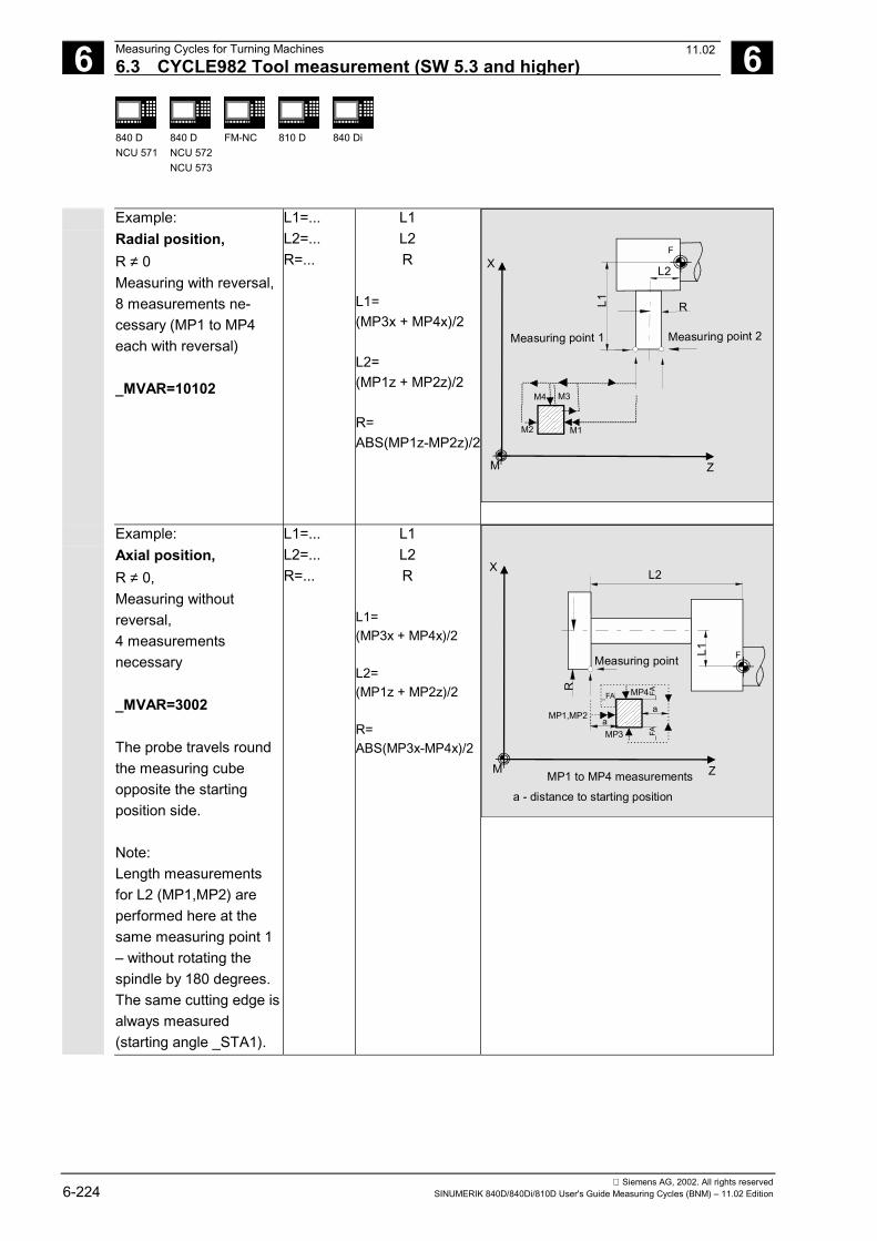
6 Measuring Cycles for Turning Machines 12.976.3 CYCLE982 Tool measurement (SW 5.3 and higher) 6
840 DNCU 571
840 DNCU 572NCU 573
FM-NC 810 D 840 Di
Siemens AG, 2002. All rights reserved6-224 SINUMERIK 840D/840Di/810D User's Guide Measuring Cycles (BNM) – 11.02 Edition
Example:Radial position,R ≠ 0Measuring with reversal,8 measurements ne-cessary (MP1 to MP4each with reversal)
_MVAR=10102
L1=...L2=...R=...
L1L2R
L1=(MP3x + MP4x)/2
L2=(MP1z + MP2z)/2
R=ABS(MP1z-MP2z)/2
X
ZM
L2
FF
L1 R
Measuring point 1 Measuring point 2
M1M2
M4 M3
Example:Axial position,R ≠ 0,Measuring withoutreversal,4 measurementsnecessary
_MVAR=3002
The probe travels roundthe measuring cubeopposite the startingposition side.
Note:Length measurementsfor L2 (MP1,MP2) areperformed here at thesame measuring point 1– without rotating thespindle by 180 degrees.The same cutting edge isalways measured(starting angle _STA1).
L1=...L2=...R=...
L1L2R
L1=(MP3x + MP4x)/2
L2=(MP1z + MP2z)/2
R=ABS(MP3x-MP4x)/2
X
ZM
FL1
L2R
Measuring point
MP1,MP2
MP3
MP4
aa
_FA
_FA
_FA
a - distance to starting position
MP1 to MP4 measurements
11.02
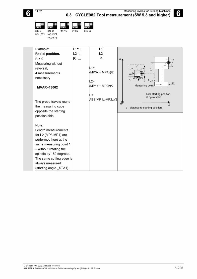
6 12.97 Measuring Cycles for Turning Machines6.3 CYCLE982 Tool measurement (SW 5.3 and higher) 6
840 DNCU 571
840 DNCU 572NCU 573
FM-NC 810 D 840 Di
Siemens AG, 2002. All rights reservedSINUMERIK 840D/840Di/810D User's Guide Measuring Cycles (BNM) – 11.02 Edition 6-225
Example:Radial position,R ≠ 0Measuring withoutreversal,4 measurementsnecessary
_MVAR=13002
The probe travels roundthe measuring cubeopposite the startingposition side.
Note:Length measurementsfor L2 (MP3 MP4) areperformed here at thesame measuring point 1– without rotating thespindle by 180 degrees.The same cutting edge isalways measured(starting angle _STA1).
L1=...L2=...R=...
L1L2R
L1=(MP3x + MP4x)/2
L2=(MP1z + MP2z)/2
R=ABS(MP1z-MP2z)/2
X
ZM
L2
FF
L1
R
M1_FA _FA
MP2
Tool starting positionat cycle start
MP4MP3a
a - distance to starting position
a
Measuring point
11.02
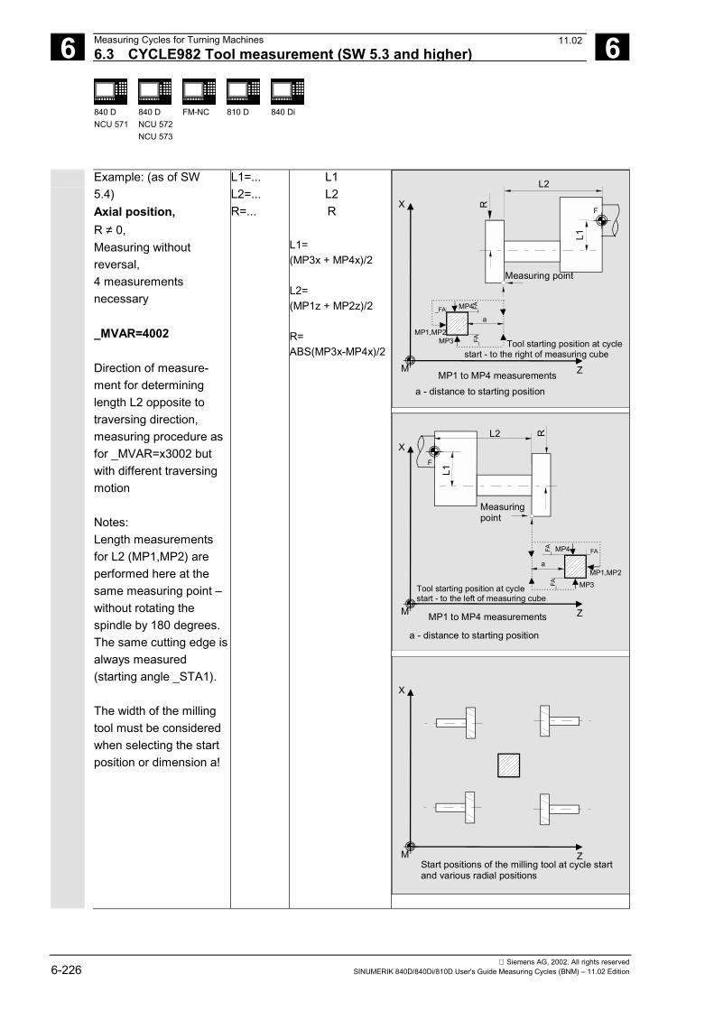
6 Measuring Cycles for Turning Machines 12.976.3 CYCLE982 Tool measurement (SW 5.3 and higher) 6
840 DNCU 571
840 DNCU 572NCU 573
FM-NC 810 D 840 Di
Siemens AG, 2002. All rights reserved6-226 SINUMERIK 840D/840Di/810D User's Guide Measuring Cycles (BNM) – 11.02 Edition
Example: (as of SW5.4)Axial position,R ≠ 0,Measuring withoutreversal,4 measurementsnecessary
_MVAR=4002
Direction of measure-ment for determininglength L2 opposite totraversing direction,measuring procedure asfor _MVAR=x3002 butwith different traversingmotion
Notes:Length measurementsfor L2 (MP1,MP2) areperformed here at thesame measuring point –without rotating thespindle by 180 degrees.The same cutting edge isalways measured(starting angle _STA1).
The width of the millingtool must be consideredwhen selecting the startposition or dimension a!
L1=...L2=...R=...
L1L2R
L1=(MP3x + MP4x)/2
L2=(MP1z + MP2z)/2
R=ABS(MP3x-MP4x)/2
X
ZM
F
L1
L2
R
Measuring point
MP1,MP2MP3
MP4
a
_FA
_FA
_FA
a - distance to starting positionMP1 to MP4 measurements
Tool starting position at cyclestart - to the right of measuring cube
X
ZM
F
L1L2 R
Measuring point
MP1,MP2MP3
MP4
a_F
A_F
A_FA
a - distance to starting position
MP1 to MP4 measurements
Tool starting position at cycle start - to the left of measuring cube
X
ZMStart positions of the milling tool at cycle start and various radial positions
11.02
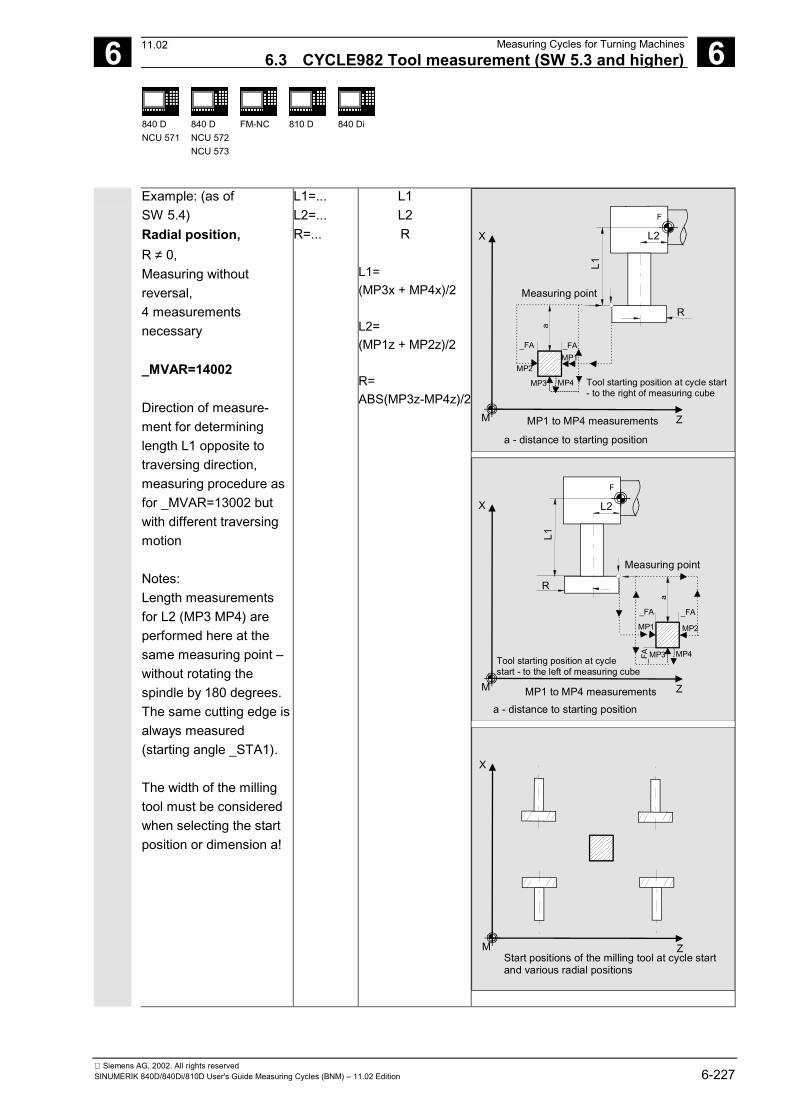
6 12.97 Measuring Cycles for Turning Machines6.3 CYCLE982 Tool measurement (SW 5.3 and higher) 6
840 DNCU 571
840 DNCU 572NCU 573
FM-NC 810 D 840 Di
Siemens AG, 2002. All rights reservedSINUMERIK 840D/840Di/810D User's Guide Measuring Cycles (BNM) – 11.02 Edition 6-227
Example: (as ofSW 5.4)Radial position,R ≠ 0,Measuring withoutreversal,4 measurementsnecessary
_MVAR=14002
Direction of measure-ment for determininglength L1 opposite totraversing direction,measuring procedure asfor _MVAR=13002 butwith different traversingmotion
Notes:Length measurementsfor L2 (MP3 MP4) areperformed here at thesame measuring point –without rotating thespindle by 180 degrees.The same cutting edge isalways measured(starting angle _STA1).
The width of the millingtool must be consideredwhen selecting the startposition or dimension a!
L1=...L2=...R=...
L1L2R
L1=(MP3x + MP4x)/2
L2=(MP1z + MP2z)/2
R=ABS(MP3z-MP4z)/2
X
ZM
L2
FF
L1
R
Tool starting position at cycle start- to the right of measuring cube
a - distance to starting position
MP1_FA _FA
MP2
MP4MP3
a
MP1 to MP4 measurements
Measuring point
X
ZM
L2
FF
L1
R
Tool starting position at cycle start - to the left of measuring cube
a - distance to starting position
MP1
_FA _FA
MP2
MP4MP3a
_FA
MP1 to MP4 measurements
Measuring point
X
ZMStart positions of the milling tool at cycle startand various radial positions
11.02
6 Measuring Cycles for Turning Machines 12.976.3 CYCLE982 Tool measurement (SW 5.3 and higher) 6
840 DNCU 571
840 DNCU 572NCU 573
FM-NC 810 D 840 Di
Siemens AG, 2002. All rights reserved6-228 SINUMERIK 840D/840Di/810D User's Guide Measuring Cycles (BNM) – 11.02 Edition
6.3.4 Incremental calibration (SW 6.2 and higher)
Function
The cycle uses the calibration tool to ascertain thecurrent distance dimensions between the machine zeroand the probe trigger point and automatically loadsthem into the appropriate data area in the GUD6module. They are always calculated without empirical ormean values.
PreconditionThe lateral surfaces of the probe cube must be alignedparallel to the machining axes abscissa and ordinate.
The coordinates of the tool probe regarding themachine zero are not known before starting calibration(data field _TP[_PRNUM-1,0] to _TP[_PRNUM1,3]contains invalid values).
Length 1 and 2and the radius of the calibration tool must be knownexactly and stored in a tool offset data block.
This tool offset must be active when the cycle is called.A turning tool must be specified as the tool type (type5xy). The tool edge position must be 3.
The calibration tool (tool tip) must, before CYCLE982 isstarted, have a position that causes the probe to switchin the specified direction _MD for the measuring axis_MA within path 2 ⋅ _FA [mm].Careful when positioning manually!Damage to the probe must be avoided.
Parameters
_MVAR 100000 (6 decimal places) Calibrate tool probe incrementally_MA 1, 2 Measuring axis_MD 0, 1 Measurement direction 0 - positive, 1 - negative_PRNUM INT Probe numberThese following additional parameters are also valid:_VMS, _FA and _NMSP.See Sections 2.2 and 2.3.
11.02
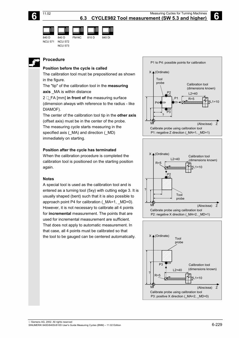
6 12.97 Measuring Cycles for Turning Machines6.3 CYCLE982 Tool measurement (SW 5.3 and higher) 6
840 DNCU 571
840 DNCU 572NCU 573
FM-NC 810 D 840 Di
Siemens AG, 2002. All rights reservedSINUMERIK 840D/840Di/810D User's Guide Measuring Cycles (BNM) – 11.02 Edition 6-229
Procedure
Position before the cycle is calledThe calibration tool must be prepositioned as shownin the figure.The "tip" of the calibration tool in the measuringaxis _MA is within distance2 ⋅ _FA [mm] in front of the measuring surface(dimension always with reference to the radius - likeDIAMOF).The center of the calibration tool tip in the other axis(offset axis) must be in the center of the probe.The measuring cycle starts measuring in thespecified axis (_MA) and direction (_MD)immediately on starting.
Position after the cycle has terminatedWhen the calibration procedure is completed thecalibration tool is positioned on the starting positionagain.
NotesA special tool is used as the calibration tool and isentered as a turning tool (5xy) with cutting edge 3. It isusually shaped (bent) such that it is also possible toapproach point P4 for calibration (_MA=1, _MD=0).However, it is not necessary to calibrate all 4 pointsfor incremental measurement. The points that areused for incremental measurement are sufficient.That does not apply to automatic measurement. Inthat case, all 4 points must be calibrated so thatthe tool to be gauged can be centered automatically.
M
L1=10F
L2=40
(Abscissa) Z
X (Ordinate)
Calibration toolToolprobe
?
(dimensions known)
Calibrate probe using calibration tool
P1P4
P3
P2
P1: negative Z direction (_MA=1, _MD=1)
P1 to P4: possible points for calibration
R=5
M
L1=10F
L2=40
(Abscissa) Z
X (Ordinate)Calibration tool
Toolprobe
?
(dimensions known)
Calibrate probe using calibration tool
P2
P2: negative X direction (_MA=2, _MD=1)
R=5
M
L2=40
(Abscissa) Z
X (Ordinate)
Calibration tool
Toolprobe
L1=10F ?(dimensions known)
Calibrate probe using calibration tool
P3
P3: positive X direction (_MA=2, _MD=0)
R=5
11.02
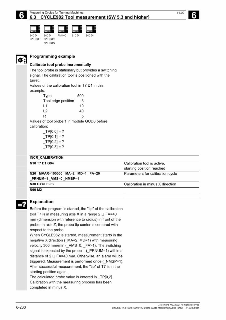
6 Measuring Cycles for Turning Machines 12.976.3 CYCLE982 Tool measurement (SW 5.3 and higher) 6
840 DNCU 571
840 DNCU 572NCU 573
FM-NC 810 D 840 Di
Siemens AG, 2002. All rights reserved6-230 SINUMERIK 840D/840Di/810D User's Guide Measuring Cycles (BNM) – 11.02 Edition
Programming example
Calibrate tool probe incrementallyThe tool probe is stationary but provides a switchingsignal. The calibration tool is positioned with theturret.Values of the calibration tool in T7 D1 in thisexample:
Type 500Tool edge position 3L1 10L2 40R 5
Values of tool probe 1 in module GUD6 beforecalibration:
_TP[0,0] = ?_TP[0,1] = ?_TP[0,2] = ?_TP[0,3] = ?
INCR_CALIBRATIONN10 T7 D1 G94 Calibration tool is active,
starting position reachedN20 _MVAR=100000 _MA=2 _MD=1 _FA=20_PRNUM=1 _VMS=0 _NMSP=1
Parameters for calibration cycle
N30 CYCLE982 Calibration in minus X directionN99 M2
ExplanationBefore the program is started, the "tip" of the calibrationtool T7 is in measuring axis X in a range 2 ⋅ _FA=40mm (dimension with reference to radius) in front of theprobe. In axis Z, the probe tip center is centered withrespect to the probe.When CYCLE982 is started, measurement starts in thenegative X direction (_MA=2, MD=1) with measuringvelocity 300 mm/min (_VMS=0, _FA>1). The switchingsignal is expected by the probe 1 (_PRNUM=1) within adistance of 2 ⋅ _FA=40 mm. Otherwise, an alarm will betriggered. Measurement is performed once (_NMSP=1).After successful measurement, the "tip" of T7 is in thestarting position again.The calculated probe value is entered in _TP[0,2].Calibration with the measuring process has beencompleted in minus X.
11.02
6 12.97 Measuring Cycles for Turning Machines6.3 CYCLE982 Tool measurement (SW 5.3 and higher) 6
840 DNCU 571
840 DNCU 572NCU 573
FM-NC 810 D 840 Di
Siemens AG, 2002. All rights reservedSINUMERIK 840D/840Di/810D User's Guide Measuring Cycles (BNM) – 11.02 Edition 6-231
6.3.5 Incremental measurement (SW 6.2 and higher)
Function
The lengths of turning tools (type 5xy) or millingtools/drills (type 1xy / 2xy) can be measured onlathes.In the case of milling tools, the miller radius offsetcan also be measured.With milling tools, the measurement is furtherspecified with the 3rd to 5th decimal places ofparameter _MVAR.The calculated offsets are entered in the activeD number. The offset is entered in the geometrydata and the wear data are reset.Only the offset value that is in the measuring axis_MA can be determined in a measurement.
If _CHBIT[20]=1, positioning of the milling spindle atthe value of _STA1 can be suppressed.This is possible with the following miller measurementvariants:_MVAR= xxx001(with x : 0 or 1, no other values).
General preconditionsFor incremental measurement, the tool probe mustbe calibrated in the measuring axis and direction inwhich measuring will be performed.The tool T to be measured must be called with toollength offset (D number).The tool type is entered in the offset data.
For mills/drills, setting data SD 42950:TOOL_LENGTH_TYPE =2 must be set (lengthcalculation as for turning tool). For milling tools, the toolspindle must be declared the master spindle.
11.02
6 Measuring Cycles for Turning Machines 12.976.3 CYCLE982 Tool measurement (SW 5.3 and higher) 6
840 DNCU 571
840 DNCU 572NCU 573
FM-NC 810 D 840 Di
Siemens AG, 2002. All rights reserved6-232 SINUMERIK 840D/840Di/810D User's Guide Measuring Cycles (BNM) – 11.02 Edition
Parameters
_MVAR 1xxxx1(6 decimal places)
Measuring a tool incrementallyMore precise specification for milling tools via the 3rdto 5th decimal places
_MA 1, 2 Measuring axis_MD 0, 1 Measurement direction 0 - positive, 1 - negative_STA1 For milling tools only:
Starting angle of the milling spindle_CORA Only for milling tools and measurement with reversal:
Offset angle position of the milling spindle after reversal
These following additional parameters are also valid:_VMS, _FA, _PRNUM and _NMSP.See Sections 2.2 and 2.3.
Procedure
Position before the cycle is calledBefore the cycle is called, a starting position must beapproached - as shown in the figure for turningtools, e.g.: by traversing in JOG mode.The "tip" of the tool in the measuring axis _MA iswithin the distance2 ⋅ _FA [mm] in front of the measuring surface(dimension always with reference to the radius - likeDIAMOF).The center of the cutting edge radius on the turningtool in the other axis is in the center of the probe. Ifthe cutting edge radius =0, it is the tool nose.For milling tools, the axial or radial position of thetool must be specified in _MVAR;as must measurement with reversal:First the measuring point is measured in the selec-ted axis and in a milling spindle position according tostarting angle _STA1. The tool (milling spindle) isthen rotated through 180 degrees plus the value in_CORA and measured again. The average value isthe measured value.If the milling spindle is activated when the cycle isstarted, measurement will be performed with a rota-ting spindle. In that case, the user must exercisespecial care when selecting the speed, direction ofrotation, and feedrate!
X
ZM Various start positions and measuring directions in the axes
Tool nose(turning tool)
2 * _FA
11.02
6 12.97 Measuring Cycles for Turning Machines6.3 CYCLE982 Tool measurement (SW 5.3 and higher) 6
840 DNCU 571
840 DNCU 572NCU 573
FM-NC 810 D 840 Di
Siemens AG, 2002. All rights reservedSINUMERIK 840D/840Di/810D User's Guide Measuring Cycles (BNM) – 11.02 Edition 6-233
If _CHBIT[20]=1, selected measurement variants arepossible for a milling cutter without taking thestarting angle _STA1 into account.
Position after the cycle has terminatedWhen the cycle is completed, the tooltip is back in the starting position.
Measurement variant Specifiedgeometry
Offsetin
Milling tools, drills
Example:Axial position,drill, R=0,incrementalmeasurement withoutreversal,calculation of the lengthin Z
_MVAR=100001_MA=1
Values L1 ≠ 0 are alsopossible.But always position thedrill tip in the center ofthe probe!
L1=0L2=...R=0
L2
X
ZM
F
L2 = ?
F
Example:Radial position,drill, R=0,measuring withoutreversal,calculation of the lengthin X
_MVAR=110001_MA=2
L1=...L2=...R=0
L1=...
X
ZM
L2
F
L1 =
?
F
11.02
6 Measuring Cycles for Turning Machines 12.976.3 CYCLE982 Tool measurement (SW 5.3 and higher) 6
840 DNCU 571
840 DNCU 572NCU 573
FM-NC 810 D 840 Di
Siemens AG, 2002. All rights reserved6-234 SINUMERIK 840D/840Di/810D User's Guide Measuring Cycles (BNM) – 11.02 Edition
Example:Axial position,miller, R ≠ 0,measuring withoutreversal,calculation of the lengthin Z
_MVAR=100001_MA=1
L1= -...L2=...R=...
L2
X
ZM
F
F
L2 = ?
R
L1
Example:Radial position,miller, R ≠ 0,measuring withoutreversal,calculation of the lengthin X
_MVAR=110001_MA=2
L1=...L2=...R=...
L1
X
ZM
L2
F
L1 =
?R
F
Example:Axial position,miller, R ≠ 0,measuring with reversal,calculate radius
_MVAR=101101_MA=2
In this case, L1 must beknown
L1=....L2=...R=...
R
X
ZM
F
F
L2 = ?
R
L1
11.02
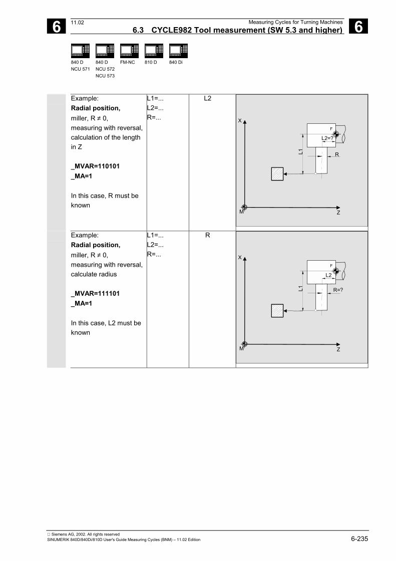
6 12.97 Measuring Cycles for Turning Machines6.3 CYCLE982 Tool measurement (SW 5.3 and higher) 6
840 DNCU 571
840 DNCU 572NCU 573
FM-NC 810 D 840 Di
Siemens AG, 2002. All rights reservedSINUMERIK 840D/840Di/810D User's Guide Measuring Cycles (BNM) – 11.02 Edition 6-235
Example:Radial position,miller, R ≠ 0,measuring with reversal,calculation of the lengthin Z
_MVAR=110101_MA=1
In this case, R must beknown
L1=...L2=...R=...
L2
X
ZM
L2=?
FF
L1 R
Example:Radial position,miller, R ≠ 0,measuring with reversal,calculate radius
_MVAR=111101_MA=1
In this case, L2 must beknown
L1=...L2=...R=...
R
X
ZM
L2
FF
L1 R=?
11.02
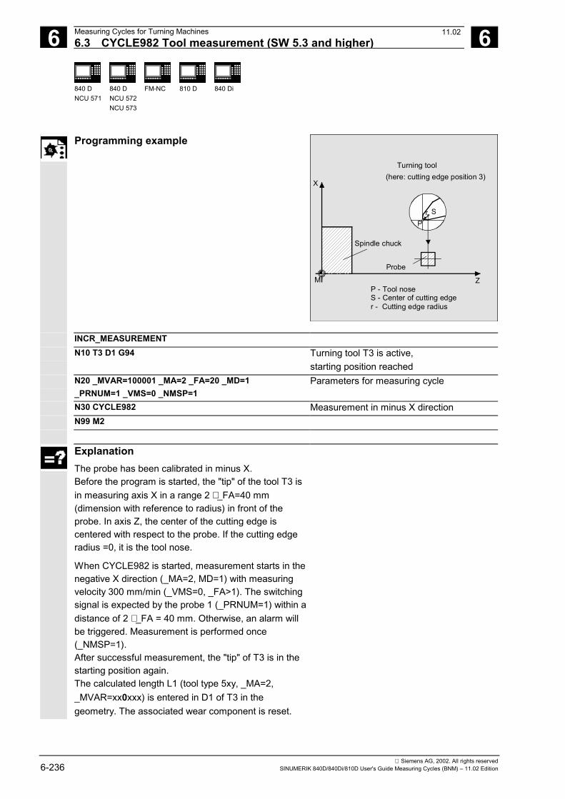
6 Measuring Cycles for Turning Machines 12.976.3 CYCLE982 Tool measurement (SW 5.3 and higher) 6
840 DNCU 571
840 DNCU 572NCU 573
FM-NC 810 D 840 Di
Siemens AG, 2002. All rights reserved6-236 SINUMERIK 840D/840Di/810D User's Guide Measuring Cycles (BNM) – 11.02 Edition
Programming example
S
X
Z
rP
Probe
M
Spindle chuck
Turning tool (here: cutting edge position 3)
P - Tool noseS - Center of cutting edger - Cutting edge radius
INCR_MEASUREMENTN10 T3 D1 G94 Turning tool T3 is active,
starting position reachedN20 _MVAR=100001 _MA=2 _FA=20 _MD=1_PRNUM=1 _VMS=0 _NMSP=1
Parameters for measuring cycle
N30 CYCLE982 Measurement in minus X directionN99 M2
ExplanationThe probe has been calibrated in minus X.Before the program is started, the "tip" of the tool T3 isin measuring axis X in a range 2 ⋅ _FA=40 mm(dimension with reference to radius) in front of theprobe. In axis Z, the center of the cutting edge iscentered with respect to the probe. If the cutting edgeradius =0, it is the tool nose.
When CYCLE982 is started, measurement starts in thenegative X direction (_MA=2, MD=1) with measuringvelocity 300 mm/min (_VMS=0, _FA>1). The switchingsignal is expected by the probe 1 (_PRNUM=1) within adistance of 2 ⋅ _FA = 40 mm. Otherwise, an alarm willbe triggered. Measurement is performed once(_NMSP=1).After successful measurement, the "tip" of T3 is in thestarting position again.The calculated length L1 (tool type 5xy, _MA=2,_MVAR=xx0xxx) is entered in D1 of T3 in thegeometry. The associated wear component is reset.
11.02
6 12.97 Measuring Cycles for Turning Machines6.3 CYCLE982 Tool measurement (SW 5.3 and higher) 6
840 DNCU 571
840 DNCU 572NCU 573
FM-NC 810 D 840 Di
Siemens AG, 2002. All rights reservedSINUMERIK 840D/840Di/810D User's Guide Measuring Cycles (BNM) – 11.02 Edition 6-237
6.3.6 Milling tool: suppression of starting angle positioning with _STA1(SW 6.2 and higher)
Function
To accept the angular position of the milling spindle(cutting edge of the miller contacting the probe)unchanged into the cycle and thus suppress the startingangle positioning with the value in _STA1, you can set
_CHBIT[20]=1
However, this only permits the simple millermeasurement variants that do not have to access thestarting angle in _STA1, e.g.: no 2nd measurement orrepositioning after measurement with reversal.Otherwise, those miller measurement variants arepossible that are also permitted during incrementalmeasurement.
If the machine does not feature an SPOS-capablemilling spindle, it is also possible to measure millerswith these measurement variants and _CHBIT[20]=1.
Permissible measurement variants with miller and_CHBIT[20]=1:
xxx001 (with x : 0 or 1, no other values)
Other measurement variants with a miller will berejected with an alarm message.
For measurement with a rotating spindle and_CHBIT[20]=1, these are also the only measurementvariants permitted. Measurement with reversal is notpermitted.
11.02
6 Measuring Cycles for Turning Machines 12.976.4 CYCLE973 Calibrate workpiece probe 6
840 DNCU 571
840 DNCU 572NCU 573
FM-NC 810 D 840 Di
Siemens AG, 2002. All rights reserved6-238 SINUMERIK 840D/840Di/810D User's Guide Measuring Cycles (BNM) – 11.02 Edition
6.4 CYCLE973 Calibrate workpiece probe
Programming
CYCLE973
Function
With this cycle the workpiece probe can becalibrated either in a reference groove or on asurface.
Result parameters
Measuring cycle CYCLE973 returns the followingresult values in the GUD5 module:
_OVR [4] REAL Actual value probe ball diameter _OVR [5] REAL Difference probe ball diameter _OVR [8] REAL Trigger point in minus direction, actual value, abscissa _OVR [10] REAL Trigger point in plus direction, actual value, abscissa _OVR [12] REAL Trigger point in minus direction, actual value, ordinate _OVR [14] REAL Trigger point in plus direction, actual value, ordinate _OVR [9] REAL Trigger point in minus direction, difference, abscissa _OVR [11] REAL Trigger point in plus direction, difference, abscissa _OVR [13] REAL Trigger point in minus direction, difference, ordinate _OVR [15] REAL Trigger point in plus direction, difference, ordinate _OVR [20] REAL Positional deviation abscissa _OVR [21] REAL Positional deviation ordinate _OVR [27] REAL Zero offset area _OVR [28] REAL Safe area _OVI [2] INTEGER Measuring cycle number _OVI [5] INTEGER Probe number _OVI [9] INTEGER Alarm number
09.01
6 12.97 Measuring Cycles for Turning Machines6.4 CYCLE973 Calibrate workpiece probe 6
840 DNCU 571
840 DNCU 572NCU 573
FM-NC 810 D 840 Di
Siemens AG, 2002. All rights reservedSINUMERIK 840D/840Di/810D User's Guide Measuring Cycles (BNM) – 11.02 Edition 6-239
Measurement variants
The measuring cycle CYCLE973 permits the followingcalibration variant that are defined via the parameter_MVAR. The possible values of the parameter are between0 ... 12113 and are formed as follows:
Digit Meaning 5 4 3 2 1 0 No position calculation 1 With position calculation only for calibration in groove 1 1 axis direction (indicate measuring axis and axis direction) 2 2 axis directions only for calibration in slot (specifying measuring axis) 0 No calculation of probe ball 1 Calculation of probe ball (only for calibration in groove) 0 0 Any surface 1 3 Groove 0 With any data in the plane 1 With reference data in the plane
11.02
6 Measuring Cycles for Turning Machines 12.976.4 CYCLE973 Calibrate workpiece probe 6
840 DNCU 571
840 DNCU 572NCU 573
FM-NC 810 D 840 Di
Siemens AG, 2002. All rights reserved6-240 SINUMERIK 840D/840Di/810D User's Guide Measuring Cycles (BNM) – 11.02 Edition
6.4.1 CYCLE973 Calibrate in the reference groove (plane)
Function
With this measuring cycle, it is possible to calibratethe probe in a reference groove. Calibration in thereference groove is possible in the abscissa andordinate. The calculated setpoint/actual value difference isoffset against the probe length. The newly calculatedtrigger values are then loaded into the correspondingdata area of the module GUD6.DEF. Calibration is only performed on one surface (axisdirection) in the groove. Precondition The probe must be called with tool offset. Onlyprobes with "tool edge position" 7 or 8 can be used(see Subsection 1.5.2). The valid reference groove is selected with_CALNUM.
Parameters
_MVAR see Section 6.4 Definition of calibration variant _MA 1, 2 Measuring axis _MD 0 positive axis direction
1 negative axis direction Measuring direction (depends on themeasurement variant)
_CALNUM INT Number of calibration groove _PRNUM INT Probe number
These following additional parameters are also valid: _VMS, _TZL, _TSA, _FA and _NMSP. See Sections 2.2 and 2.3.
09.01
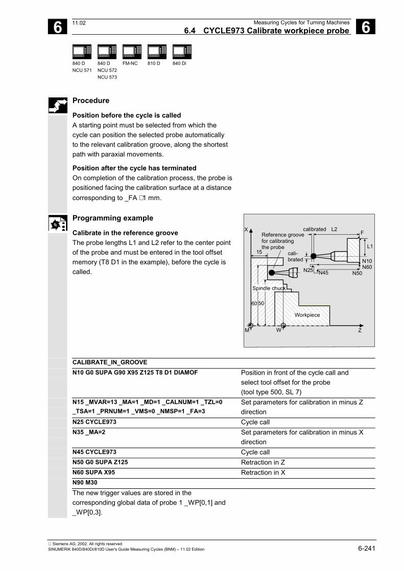
6 12.97 Measuring Cycles for Turning Machines6.4 CYCLE973 Calibrate workpiece probe 6
840 DNCU 571
840 DNCU 572NCU 573
FM-NC 810 D 840 Di
Siemens AG, 2002. All rights reservedSINUMERIK 840D/840Di/810D User's Guide Measuring Cycles (BNM) – 11.02 Edition 6-241
Procedure
Position before the cycle is called A starting point must be selected from which thecycle can position the selected probe automaticallyto the relevant calibration groove, along the shortestpath with paraxial movements. Position after the cycle has terminated On completion of the calibration process, the probe ispositioned facing the calibration surface at a distancecorresponding to _FA ⋅ 1 mm.
Programming example
Calibrate in the reference groove The probe lengths L1 and L2 refer to the center pointof the probe and must be entered in the tool offsetmemory (T8 D1 in the example), before the cycle iscalled.
X
15
Reference groovefor calibratingthe probe
60 50
Workpiece
M W
cali-brated
L2 F
L1
N10N60
N50N45N25
calibrated
Z
Spindle chuck
CALIBRATE_IN_GROOVE N10 G0 SUPA G90 X95 Z125 T8 D1 DIAMOF Position in front of the cycle call and
select tool offset for the probe(tool type 500, SL 7)
N15 _MVAR=13 _MA=1 _MD=1 _CALNUM=1 _TZL=0_TSA=1 _PRNUM=1 _VMS=0 _NMSP=1 _FA=3
Set parameters for calibration in minus Zdirection
N25 CYCLE973 Cycle call N35 _MA=2 Set parameters for calibration in minus X
direction N45 CYCLE973 Cycle call N50 G0 SUPA Z125 Retraction in Z N60 SUPA X95 Retraction in X N90 M30 The new trigger values are stored in the
corresponding global data of probe 1 _WP[0,1] and_WP[0,3].
11.02
6 Measuring Cycles for Turning Machines 12.976.4 CYCLE973 Calibrate workpiece probe 6
840 DNCU 571
840 DNCU 572NCU 573
FM-NC 810 D 840 Di
Siemens AG, 2002. All rights reserved6-242 SINUMERIK 840D/840Di/810D User's Guide Measuring Cycles (BNM) – 11.02 Edition
6.4.2 CYCLE973 Calibrate on a random surface
Function
With this measuring cycle, you can calibrate the probeon a random surface, e.g. on the workpiece, todetermine the trigger points. Precondition The probe is called up with tool offset and positionedopposite the calibrating surface. 500 should be enteredas the tool type. Measuring cycle SW 6.2 and higher alsoallows you to enter tool type 580 (probe). Tool edgepositions 5 to 8 are permitted. For calibration in the plus direction below the turningcenter or to the left of the workpiece zero, the setpoint_SETVAL must be specified as a negative value.
Parameters
_MVAR 0 Calibration variant: Calibration on randomsurface
_SETVAL REAL Setpoint referred to the workpiece zero, forfacing axis in the diameter
_MA 1, 2, 31) Measuring axis _MD 0 positive axis direction
1 negative axis direction Measurement direction
_PRNUM INT Probe number
1) As of measuring cycles SW 5.4, it is also possibleto calibrate in the 3rd axis (Y in G18), provided thatthis axis exists.
These following additional parameters are also valid: _VMS, _TZL, _TSA, _FA and _NMSP. See Sections 2.2 and 2.3.
11.02
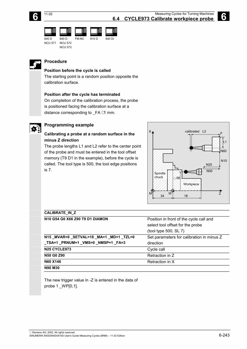
6 12.97 Measuring Cycles for Turning Machines6.4 CYCLE973 Calibrate workpiece probe 6
840 DNCU 571
840 DNCU 572NCU 573
FM-NC 810 D 840 Di
Siemens AG, 2002. All rights reservedSINUMERIK 840D/840Di/810D User's Guide Measuring Cycles (BNM) – 11.02 Edition 6-243
Procedure
Position before the cycle is called The starting point is a random position opposite thecalibration surface. Position after the cycle has terminated On completion of the calibration process, the probeis positioned facing the calibration surface at adistance corresponding to _FA ⋅ 1 mm.
Programming example
Calibrating a probe at a random surface in theminus Z direction The probe lengths L1 and L2 refer to the center pointof the probe and must be entered in the tool offsetmemory (T9 D1 in the example), before the cycle iscalled. The tool type is 500, the tool edge positionsis 7.
X
Workpiece
M W
L2 F
L1
N60
N10
N50
calibrated
Z34 18
66∅
N25
Spindlechuck
CALIBRATE_IN_Z N10 G54 G0 X66 Z90 T9 D1 DIAMON Position in front of the cycle call and
select tool offset for the probe(tool type 500, SL 7)
N15 _MVAR=0 _SETVAL=18 _MA=1 _MD=1 _TZL=0_TSA=1 _PRNUM=1 _VMS=0 _NMSP=1 _FA=3
Set parameters for calibration in minus Zdirection
N25 CYCLE973 Cycle call N50 G0 Z90 Retraction in Z N60 X146 Retraction in X N90 M30
The new trigger value in -Z is entered in the data ofprobe 1 _WP[0,1].
11.02
6 Measuring Cycles for Turning Machines 12.976.5 CYCLE974 Workpiece measurement 6
840 DNCU 571
840 DNCU 572NCU 573
FM-NC 810 D 840 Di
Siemens AG, 2002. All rights reserved6-244 SINUMERIK 840D/840Di/810D User's Guide Measuring Cycles (BNM) – 11.02 Edition
6.5 CYCLE974 Workpiece measurement
Programming
CYCLE974
Function
The measuring cycle ascertains the actual value ofthe workpiece in the selected measuring axis withreference to the workpiece zero and calculates thesetpoint/actual value difference. Both an empirical value stored in the GUD5 moduleand a mean value over several parts can beconsidered. The cycle checks that a set tolerancerange for the measured deviation is not violated andautomatically corrects the ZO memory or tool offsetmemory selected in _KNUM. Measurement ispossible in all directions permitted by the tool edgepositions of the probe.
Result parameters
Depending on the measurement variant, measuringcycle CYCLE974 returns the following result valuesin the GUD5 module:
_OVR [0] REAL Setpoint for measuring axis _OVR [1] REAL Setpoint for abscissa _OVR [2] REAL Setpoint for ordinate _OVR [3] REAL Setpoint for applicate _OVR [4] REAL Actual value for measuring axis _OVR [8] 1) REAL Upper tolerance limit for measuring axis _OVR [12] 1) REAL Lower tolerance limit for measuring axis _OVR [16] REAL Difference for measuring axis _OVR [20] 1) REAL Offset value _OVR [27] 1) REAL Zero offset area _OVR [28] REAL Safe area _OVR [29] 1) REAL Dimensional difference _OVR [30] REAL Empirical value _OVR [31] 1) REAL Mean value _OVI [0] INTEGER D number or ZO number
09.01
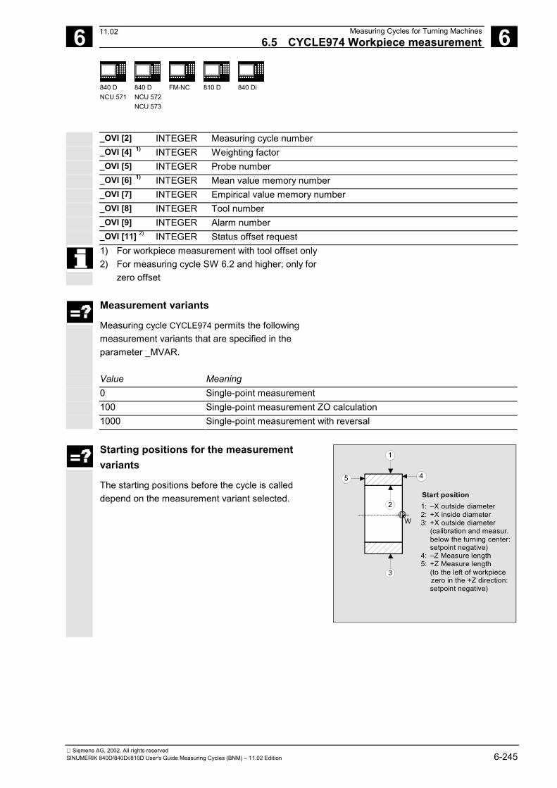
6 12.97 Measuring Cycles for Turning Machines6.5 CYCLE974 Workpiece measurement 6
840 DNCU 571
840 DNCU 572NCU 573
FM-NC 810 D 840 Di
Siemens AG, 2002. All rights reservedSINUMERIK 840D/840Di/810D User's Guide Measuring Cycles (BNM) – 11.02 Edition 6-245
_OVI [2] INTEGER Measuring cycle number _OVI [4] 1) INTEGER Weighting factor _OVI [5] INTEGER Probe number _OVI [6] 1) INTEGER Mean value memory number _OVI [7] INTEGER Empirical value memory number _OVI [8] INTEGER Tool number _OVI [9] INTEGER Alarm number _OVI [11] 2) INTEGER Status offset request
1) For workpiece measurement with tool offset only2) For measuring cycle SW 6.2 and higher; only for
zero offset
Measurement variants
Measuring cycle CYCLE974 permits the followingmeasurement variants that are specified in theparameter _MVAR.
Value Meaning 0 Single-point measurement 100 Single-point measurement ZO calculation 1000 Single-point measurement with reversal
Starting positions for the measurementvariants
The starting positions before the cycle is calleddepend on the measurement variant selected.
1
5 4
2
3
Start position1: –X outside diameter2: +X inside diameter3: +X outside diameter (calibration and measur. below the turning center: setpoint negative)4: –Z Measure length5: +Z Measure length (to the left of workpiece zero in the +Z direction: setpoint negative)
W
11.02
6 Measuring Cycles for Turning Machines 12.976.5 CYCLE974 Workpiece measurement 6
840 DNCU 571
840 DNCU 572NCU 573
FM-NC 810 D 840 Di
Siemens AG, 2002. All rights reserved6-246 SINUMERIK 840D/840Di/810D User's Guide Measuring Cycles (BNM) – 11.02 Edition
6.5.1 CYCLE974 Single-point measurement ZO calculation
Function
With this measurement variant, the actual value of ablank is acquired with reference to the workpiecezero in the selected measuring axis. An empirical value from the GUD5 module can beincluded with the correct sign. The automatic offset in the ZO memory is additivedepending on the value of the parameter _KNUM. Ifa fine offset is active (MD 18600:MM_FRAME_FINE_TRANS), an additive ZO will beimplemented in it, otherwise it is implemented in thecoarse offset. Precondition If necessary, the workpiece must be positioned inthe correct angular spindle position with SPOSbefore the cycle is called. The probe must be calibrated in the measuring directionand called with tool offset. The tool type is 500.Measuring cycle SW 6.2 and higher also allows you toenter tool type 580 (probe). The tool edge position canbe 5 to 8. The maximum diameter to be measured depends onthe traverse range of the turret slide in the plus Xdirection.
11.02
6 12.97 Measuring Cycles for Turning Machines6.5 CYCLE974 Workpiece measurement 6
840 DNCU 571
840 DNCU 572NCU 573
FM-NC 810 D 840 Di
Siemens AG, 2002. All rights reservedSINUMERIK 840D/840Di/810D User's Guide Measuring Cycles (BNM) – 11.02 Edition 6-247
Parameters
_MVAR 100 Measurement variant: Single-pointmeasurement ZO calculation
_SETVAL REAL1) Setpoint, with reference to the workpiece zero _MA 1, 2, 31) Measuring axis _KNUM 0 No automatic
ZO compensation;1...99 Automatic ZO compensation
in G54...G57, G505...G599
With/without automatic ZO calculation
Measuringcycles SW4.4 andhigher
1000 Automatic ZO compensationin basic frame G5002)
Measuringcycles SW6.2 andhigher2)
1011...1026 automatic ZO compensation in 1st to 16th basic frame (channel) ($P_CHBFR[0]...$P_CHBFR[15])
2000 automatic ZO compensation in system framescratching system frame ($P_SETFR)
9999 automatic ZO compensation in an active frame settable frames G54..G57, G505...G599 or
for G500 in last active basic frame according to $P_CHBFRMASK (most significant bit)
1) As of measuring cycles SW 5.4, measuring is also possible
in the 3rd axis of the plane (Y in G18), provided that this axisexists. Moreover, for measurement in the 3rd axis of theplane with active G18 (measurement in the Y axis), thesame setpoint parameterization can be used as formeasurement in the X axis (transverse axis), if CHBIT[19]=1is set in module GUD6. The offset is then stored in the Xcomponent of the selected ZO memory.
2) As of measuring cycles SW 5.3, compensation is carried outin the last basic frame (per MD 28081:MM_NUM_BASE_FRAMES) if more than one is available. Ifmeasuring cycles higher than SW 5.3 are used at a controlwith SW 4, parameter _SI[1] in the GUD 6 module must beset to 4!
3) Measuring cycles version SW 6.2 and higher can only beused with NCK-SW 6.3 and higher.
The following additional parameters are also valid: _VMS, _TSA, _FA, _PRNUM, _EVNUM and _NMSP. See Sections 2.2 and 2.3.
If the parameter _VMS has value 0, the default value of themeasuring cycle is used for the variable measuring velocity.
11.02
6 Measuring Cycles for Turning Machines 12.976.5 CYCLE974 Workpiece measurement 6
840 DNCU 571
840 DNCU 572NCU 573
FM-NC 810 D 840 Di
Siemens AG, 2002. All rights reserved6-248 SINUMERIK 840D/840Di/810D User's Guide Measuring Cycles (BNM) – 11.02 Edition
Procedure
Position before the cycle is called The probe must be positioned opposite the surface to bemeasured. Position after the cycle has terminated On completion of the measuring process, the probe ispositioned facing the calibration surface at a distancecorresponding to _FA ⋅ 1 mm.
Notice!Precise measurement is only possible with a probe calibratedunder the measurement conditions, i.e. working plane andmeasuring velocity are the same for both measurement andcalibration. If the probe is used in the spindle for a poweredtool, the orientation of the spindle must also be considered.Deviations can cause additional measuring errors.
Programming example
ZO calculation at a workpiece
X
Workpiece
M W
L2 F
L1
N25
N5
N20
calibrated
ZZMW _SETVAL
Spindlechuck
36∅
G54
_FA
N15
ZO_CALCULATION_1 N01 G18 T8 D3 Call probe
(tool type 500, SL 7) N05 G0 G90 G54 X36 Z100 Starting position before the cycle is called N10 _MVAR=100 _SETVAL=60 _MA=1 _TSA=1
_KNUM=1 _EVNUM=0 _PRNUM=1 _VMS=0 _NMSP=1_FA=1
Parameters for cycle call
N15 CYCLE974 Measurement in the Z direction N20 G0 Z100 Retraction in Z N25 X114 Retraction in X N90 M30
11.02
6 12.97 Measuring Cycles for Turning Machines6.5 CYCLE974 Workpiece measurement 6
840 DNCU 571
840 DNCU 572NCU 573
FM-NC 810 D 840 Di
Siemens AG, 2002. All rights reservedSINUMERIK 840D/840Di/810D User's Guide Measuring Cycles (BNM) – 11.02 Edition 6-249
6.5.2 CYCLE974 Single-point measurement
Function
With this measurement variant the actual value of aworkpiece is acquired with reference to theworkpiece zero in the selected measuring axis. An empirical value from the GUD5 module can beincluded with the correct sign. A mean valuederivation over several parts is possible as anoption. The automatic tool offset is additive depending onthe value of the parameter _KNUM; observance ofset tolerance ranges is checked. Precondition If necessary, the workpiece must be positioned inthe correct angular spindle position with SPOSbefore the cycle is called. The probe must be calibrated in the measuring directionand called with tool offset. The tool type is 500.Measuring cycle SW 6.2 also allows you to enter tooltype 580 (probe). The tool edge position can be 5 to 8. The maximum diameter to be measured depends onthe traverse range of the turret slide in the plus Xdirection.
11.02
6 Measuring Cycles for Turning Machines 12.976.5 CYCLE974 Workpiece measurement 6
840 DNCU 571
840 DNCU 572NCU 573
FM-NC 810 D 840 Di
Siemens AG, 2002. All rights reserved6-250 SINUMERIK 840D/840Di/810D User's Guide Measuring Cycles (BNM) – 11.02 Edition
Parameters
_MVAR 0 Measurement variant: Single-pointmeasurement
_SETVAL REAL2) Setpoint (according to drawing) _MA 1, 2, 31) Measuring axis _KNUM 0 no automatic tool offset
> 0 automatic tool offset (D number) With/without automatic tool offset
_TNUM 1, 2, 3, .... Tool number for automatic tool offset _TNAME STRING[32] Tool name for automatic tool offset
(alternative to _TNUM with tool manage-ment active)
1) As of measuring cycles SW 5.4, it is also possible to carry
out measurement in the 3rd axis of the plane(with G18 in Y), provided that this axis exists.
2) Setting _CHBIT[19]=1 in module GUD6 enables the samesetpoint parameterization to be used for measurement inthe Y axis (3rd axis of the plane) with active G18 as formeasurement in the X axis (transverse axis). The tooloffset is then also in L1 (active length in X) if not specifieddifferently in _KNUM.
The following additional parameters are also valid: _VMS, _TZL, _TMV, _TUL, TLL, _TDIF, _TSA,_FA, _PRNUM, _EVNUM, _NMSP, and _K. See Sections 2.2 and 2.3.
Procedure
Position before the cycle is called The probe must be positioned opposite the surfaceto be measured. Position after the cycle has terminated On completion of the measuring process, the probeis positioned facing the measuring surface at adistance corresponding to _FA ⋅ 1 mm.
11.02
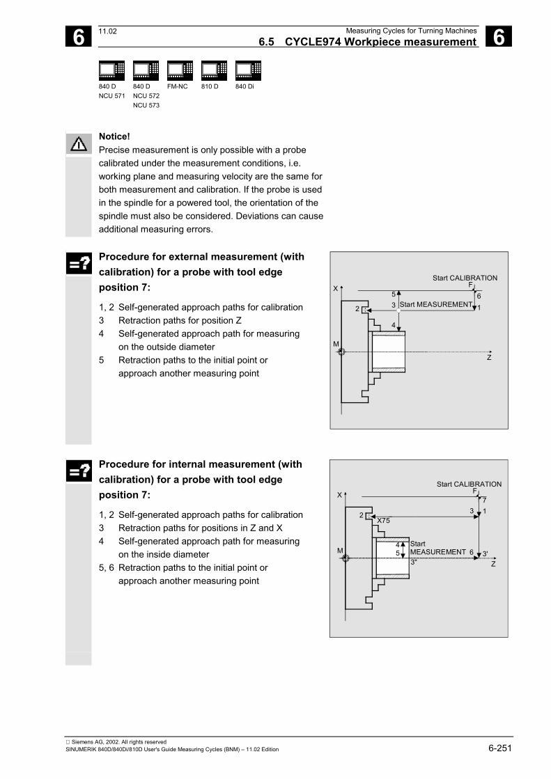
6 12.97 Measuring Cycles for Turning Machines6.5 CYCLE974 Workpiece measurement 6
840 DNCU 571
840 DNCU 572NCU 573
FM-NC 810 D 840 Di
Siemens AG, 2002. All rights reservedSINUMERIK 840D/840Di/810D User's Guide Measuring Cycles (BNM) – 11.02 Edition 6-251
Notice!Precise measurement is only possible with a probecalibrated under the measurement conditions, i.e.working plane and measuring velocity are the same forboth measurement and calibration. If the probe is usedin the spindle for a powered tool, the orientation of thespindle must also be considered. Deviations can causeadditional measuring errors.
Procedure for external measurement (withcalibration) for a probe with tool edgeposition 7:
1, 2 Self-generated approach paths for calibration 3 Retraction paths for position Z 4 Self-generated approach path for measuring on the outside diameter 5 Retraction paths to the initial point or approach another measuring point
2
53
6F
Start CALIBRATION
Start MEASUREMENT
4
1
M
X
Z
Procedure for internal measurement (withcalibration) for a probe with tool edgeposition 7:
1, 2 Self-generated approach paths for calibration 3 Retraction paths for positions in Z and X 4 Self-generated approach path for measuring on the inside diameter 5, 6 Retraction paths to the initial point or approach another measuring point
2
53"
6
FStart CALIBRATION
Start MEASUREMENT
4
X75
3'
3 17
M
X
Z
11.02
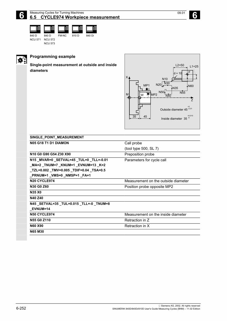
6 Measuring Cycles for Turning Machines 12.976.5 CYCLE974 Workpiece measurement 6
840 DNCU 571
840 DNCU 572NCU 573
FM-NC 810 D 840 Di
Siemens AG, 2002. All rights reserved6-252 SINUMERIK 840D/840Di/810D User's Guide Measuring Cycles (BNM) – 11.02 Edition
Programming example
Single-point measurement at outside and insidediameters
L2=50 L1=25
M W
MP1
MP2
35 45
Xd = 10 F
N10
N20 N30N35
N50 N55
N60
N40Z
Outside diameter 45+0-0.01
Inside diameter 35+0.015-0
SINGLE_POINT_MEASUREMENT N05 G18 T1 D1 DIAMON Call probe
(tool type 500, SL 7) N10 G0 G90 G54 Z30 X90 Preposition probe N15 _MVAR=0 _SETVAL=45 _TUL=0 _TLL=-0.01
_MA=2 _TNUM=7 _KNUM=1 _EVNUM=13 _K=2_TZL=0.002 _TMV=0.005 _TDIF=0.04 _TSA=0.5_PRNUM=1 _VMS=0 _NMSP=1 _FA=1
Parameters for cycle call
N20 CYCLE974 Measurement on the outside diameter N30 G0 Z60 Position probe opposite MP2 N35 X0 N40 Z40 N45 _SETVAL=35 _TUL=0.015 _TLL=-0 _TNUM=8
_EVNUM=14
N50 CYCLE974 Measurement on the inside diameter N55 G0 Z110 Retraction in Z N60 X90 Retraction in X N65 M30
09.01
6 12.97 Measuring Cycles for Turning Machines6.5 CYCLE974 Workpiece measurement 6
840 DNCU 571
840 DNCU 572NCU 573
FM-NC 810 D 840 Di
Siemens AG, 2002. All rights reservedSINUMERIK 840D/840Di/810D User's Guide Measuring Cycles (BNM) – 11.02 Edition 6-253
6.5.3 CYCLE974 Single-point measurement with reversal
Function
With this measurement variant the workpiece actualvalue is ascertained with reference to the workpiecezero in the measuring axis by acquiring two oppositepoints on the diameter. Before taking the firstmeasurement, the workpiece is positioned at theangular position programmed in parameter _STA1with SPOS and the 180° reversal is automaticallygenerated by the cycle before the secondmeasurement. An empirical value from the GUD5 module can beincluded with the correct sign. A mean valuederivation over several parts is possible as anoption. The automatic tool offset is additive depending onthe value of the parameter _KNUM; observance ofset tolerance ranges is checked. Precondition The probe must be calibrated in the measuring directionand called with tool offset. The tool type is 500.Measuring cycle SW 6.2 and higher also allows you toenter tool type 580 (probe). The tool edge position canbe 5 to 8. The maximum diameter to be measured depends onthe traverse range of the turret slide in the plus Xdirection.
11.02
6 Measuring Cycles for Turning Machines 12.976.5 CYCLE974 Workpiece measurement 6
840 DNCU 571
840 DNCU 572NCU 573
FM-NC 810 D 840 Di
Siemens AG, 2002. All rights reserved6-254 SINUMERIK 840D/840Di/810D User's Guide Measuring Cycles (BNM) – 11.02 Edition
Parameters
_MVAR 1000 Measurement variant: Single-pointmeasurement with reversal
_SETVAL REAL2) Setpoint (according to drawing) _MA 1, 2, 31) Measuring axis _STA1 REAL, positive Initial angle _KNUM 0 no automatic
tool offset > 0 automatic tool offset (D number)
With/without automatic tool offset
_TNUM 1, 2, 3, .... Tool number for automatic tool offset _TNAME STRING[32] Tool name for automatic tool offset
(alternative to _TNUM with tool managementactive)
1) As of measuring cycles SW 5.4, it is also possible to
carry out measurement in the 3rd axis of the plane(with G18 in Y), provided that this axis exists.
2) Setting _CHBIT[19]=1 in module GUD6 enables the samesetpoint parameterization to be used as for measurementin the X axis (transverse axis) for measurement in the Yaxis (3rd axis of the plane) with active G18. The tool offsetis then also in L1 (active length in X) if not specifieddifferently in _KNUM.
The following additional parameters are also valid: _VMS, _TZL, _TMV, _TUL _TLL, _TDIF, _TSA,_FA, _PRNUM, _EVNUM, _NMSP, and _K. See Sections 2.2 and 2.3.
Procedure
Position before the cycle is called The probe must be positioned opposite the surfaceto be measured. Position after the cycle has terminated On completion of the measuring process, the probeis positioned facing the measuring surface at adistance corresponding to _FA ⋅ 1 mm.
09.01
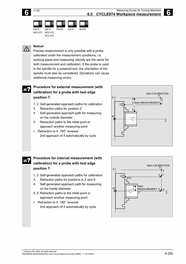
6 12.97 Measuring Cycles for Turning Machines6.5 CYCLE974 Workpiece measurement 6
840 DNCU 571
840 DNCU 572NCU 573
FM-NC 810 D 840 Di
Siemens AG, 2002. All rights reservedSINUMERIK 840D/840Di/810D User's Guide Measuring Cycles (BNM) – 11.02 Edition 6-255
Notice!Precise measurement is only possible with a probecalibrated under the measurement conditions, i.e.working plane and measuring velocity are the same forboth measurement and calibration. If the probe is usedin the spindle for a powered tool, the orientation of thespindle must also be considered. Deviations can causeadditional measuring errors.
Procedure for external measurement (withcalibration) for a probe with tool edgeposition 7:
1, 2 Self-generated approach paths for calibration 3 Retraction paths for position Z 4 Self-generated approach path for measuring on the outside diameter 5 Retraction paths to the initial point or approach another measuring point• Retraction to 4, 180° reversal 2nd approach of 4 automatically by cycle
2
53
6F
Start CALIBRATION
Start MEASUREMENT
4
1
*M
X
Z
Procedure for internal measurement (withcalibration) for a probe with tool edgeposition 7:
1, 2 Self-generated approach paths for calibration 3 Retraction paths for positions in Z and X 4 Self-generated approach path for measuring on the inside diameter 5, 6 Retraction paths to the initial point or approach another measuring point• Retraction to 4, 180° reversal
2nd approach of 4 automatically by cycle
2
53"
6
FStart CALIBRATION
Start MEASUREMENT
4
X75
3'
3 17
*M
X
Z
11.02
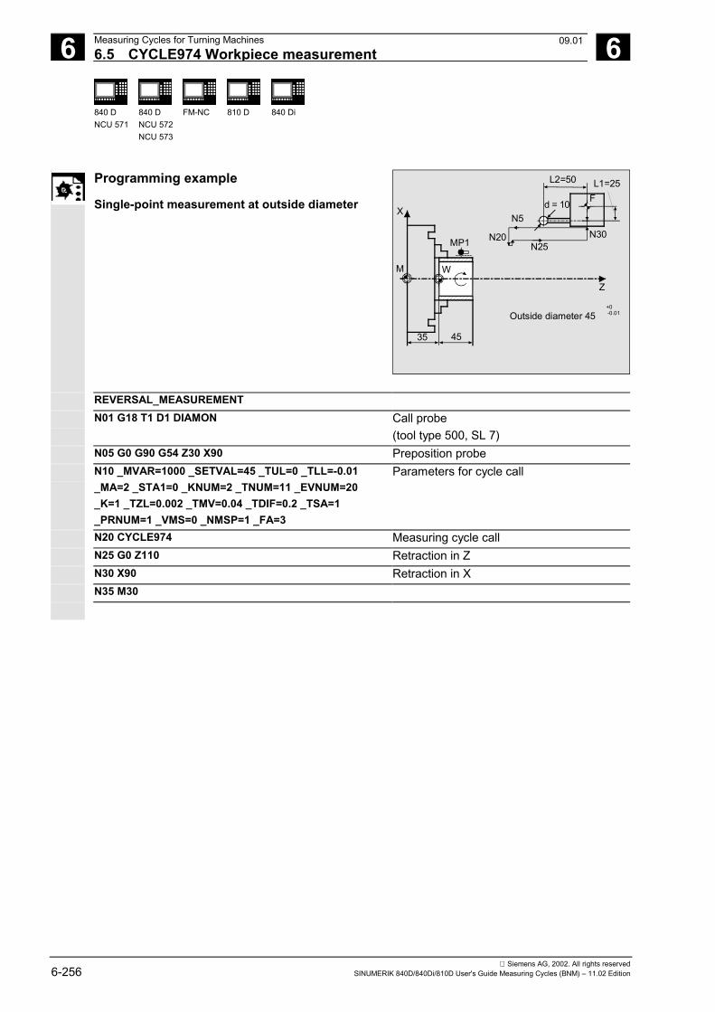
6 Measuring Cycles for Turning Machines 12.976.5 CYCLE974 Workpiece measurement 6
840 DNCU 571
840 DNCU 572NCU 573
FM-NC 810 D 840 Di
Siemens AG, 2002. All rights reserved6-256 SINUMERIK 840D/840Di/810D User's Guide Measuring Cycles (BNM) – 11.02 Edition
Programming example
Single-point measurement at outside diameter
35 45
M W
X
Z
MP1
d = 10
L2=50
FL1=25
N30N25
N5
N20
Outside diameter 45+0-0.01
REVERSAL_MEASUREMENTN01 G18 T1 D1 DIAMON Call probe
(tool type 500, SL 7)N05 G0 G90 G54 Z30 X90 Preposition probeN10 _MVAR=1000 _SETVAL=45 _TUL=0 _TLL=-0.01_MA=2 _STA1=0 _KNUM=2 _TNUM=11 _EVNUM=20_K=1 _TZL=0.002 _TMV=0.04 _TDIF=0.2 _TSA=1_PRNUM=1 _VMS=0 _NMSP=1 _FA=3
Parameters for cycle call
N20 CYCLE974 Measuring cycle callN25 G0 Z110 Retraction in ZN30 X90 Retraction in XN35 M30
09.01
6 12.97 Measuring Cycles for Turning Machines6.6 CYCLE994 Two-point measurement 6
840 DNCU 571
840 DNCU 572NCU 573
FM-NC 810 D 840 Di
Siemens AG, 2002. All rights reservedSINUMERIK 840D/840Di/810D User's Guide Measuring Cycles (BNM) – 11.02 Edition 6-257
6.6 CYCLE994 Two-point measurement
Programming
CYCLE994
Function
The measuring cycle ascertains the actual value of theworkpiece with reference to the workpiece zero andcalculates the setpoint/actual value difference. This isdone automatically by approaching two oppositemeasuring points on the diameter.
The sequence of measurements defined in the cycle –1st measuring point above on the diameter, 2ndmeasuring point below arises because a protectionzone that can be programmed in parameters _SZA and_SZO is taken into account.
An empirical value stored in the GUD5 module and amean value derivation over several parts can also betaken into account as options.The cycle checks that a set tolerance range for themeasured deviation is not violated and automaticallycorrects the tool offset memory selected in _KNUM.
PreconditionIf necessary, the workpiece must be positioned inthe correct angular spindle position with SPOSbefore the cycle is called.
The probe must be called with tool offset. Tool type 500must be specified. Measuring cycle SW 6.2 and higheralso allows you to enter tool type 580 (probe). The tooledge position can be 5 to 8.The diameter to be measured depends on the traverserange of the turret slide in the negative direction and onthe length offsets of the probe.
11.02
6 Measuring Cycles for Turning Machines 12.976.6 CYCLE994 Two-point measurement 6
840 DNCU 571
840 DNCU 572NCU 573
FM-NC 810 D 840 Di
Siemens AG, 2002. All rights reserved6-258 SINUMERIK 840D/840Di/810D User's Guide Measuring Cycles (BNM) – 11.02 Edition
Extension on measuring cycles SW 5.4 and higherThe measuring cycle can now be used for measurementwithout previous calibration. In place of the trigger values,the probe tip diameter entered in the data field of theprobe _WP[_PRNUM-1,0] is then used in the calculation.The function is controlled with bit:_CHBIT[7] = 1: without inclusion of the trigger values_CHBIT[7] = 0: as previously
Measurement variants
Measuring cycle CYCLE994 permits the followingmeasurement variants that are specified in theparameter _MVAR.Value Meaning1 Two-point measurement with programmed protection zone
(for inside measurement only)2 Two-point measurement with programmed protection zone
(for inside measurement without protection zone)
Result parameters
Measuring cycle CYCLE994 returns the followingresult values in the GUD5 module:_OVR [0] REAL Setpoint for diameter/radius_OVR [1] REAL Setpoint diameter/radius in abscissa with _MA=1 only_OVR [2] REAL Setpoint diameter/radius in ordinate with _MA=2 only_OVR [4] REAL Actual value for diameter/radius_OVR [5] REAL Actual value diameter/radius in abscissa with _MA=1 only_OVR [6] REAL Actual value diameter/radius in ordinate with _MA=2 only_OVR [8] REAL Upper Tolerance limit for diameter/radius_OVR [12] REAL Lower tolerance limit for diameter/radius_OVR [16] REAL Difference for diameter_OVR [17] REAL Difference diameter/radius in abscissa with _MA=1 only_OVR [18] REAL Difference diameter/radius in ordinate with _MA=2 only_OVR [20] REAL Offset value
_OVR [27]) REAL Zero offset area _OVR [28] REAL Safe area _OVR [29] REAL Dimensional difference _OVR [30] REAL Empirical value _OVR [31] REAL Mean value
_OVI [0] INTEGER D number
11.02
6 12.97 Measuring Cycles for Turning Machines6.6 CYCLE994 Two-point measurement 6
840 DNCU 571
840 DNCU 572NCU 573
FM-NC 810 D 840 Di
Siemens AG, 2002. All rights reservedSINUMERIK 840D/840Di/810D User's Guide Measuring Cycles (BNM) – 11.02 Edition 6-259
_OVI [2] INTEGER Measuring cycle number_OVI [4] INTEGER Weighting factor_OVI [5] INTEGER Probe number_OVI [6] INTEGER Mean value memory number_OVI [7] INTEGER Empirical value memory number_OVI [8] INTEGER Tool number_OVI [9] INTEGER Alarm number
Parameters
_MVAR 1 or 2 Measurement variant: Two-pointmeasurement with/without programmedprotection zone
_SETVAL REAL2) Setpoint (according to drawing)_MA 1, 2, 31) Measuring axis_SZA REAL Protection zone on workpiece abscissa2)
_SZO REAL Protection zone on workpiece ordinate2)
_KNUM 0 no automatic tool offset> 0 automatic tool offset (D
number)
With/without automatic tool offset
_TNUM 1, 2, 3, .... Tool number for automatic tool offset_TNAME STRING[32] Tool name for automatic tool offset (alter-
native to _TNUM with tool managementactive)
1) As of measuring cycles SW 5.4, it is possible to carry outmeasurement in the 3rd axis of the plane (with G18 in Y),provided that this axis exists.
2) For measurement in the 3rd axis (for G18 in Y, _SZOapplies in this axis, _SZA applies unchanged in the 1staxis in the plane (Z axis for G18), reversal is performed inthe 1st axis of the plane (Z axis for G18).Setting _CHBIT[19]=1 in module GUD6 enables the samesetpoint and protection zone parameterization to be usedfor measurement in the 3rd axis (measurement in the Yaxis) with active G18 as for measurement in the X axis(transverse axis). The tool offset is then also in L1 if notspecified differently in _KNUM.
The following additional parameters are also valid:_VMS, _TZL, _TMV, _TUL _TLL, _TDIF, _TSA,_FA, _PRNUM, _EVNUM, _NMSP, and _K.See Sections 2.2 and 2.3.
11.02
6 Measuring Cycles for Turning Machines 12.976.6 CYCLE994 Two-point measurement 6
840 DNCU 571
840 DNCU 572NCU 573
FM-NC 810 D 840 Di
Siemens AG, 2002. All rights reserved6-260 SINUMERIK 840D/840Di/810D User's Guide Measuring Cycles (BNM) – 11.02 Edition
ProcedurePosition before the cycle is calledThe probe must be positioned opposite the surfaceto be measured.Position after the cycle has terminatedAfter measuring has been completed, the probe isoutside the protection zone.Notice!Precise measurement is only possible with a probe calibra-ted under the measurement conditions, i.e. working planeand measuring velocity are the same for both measurementand calibration. If the probe is used in the spindle for a pow-ered tool, the orientation of the spindle must also be consi-dered. Deviations can cause additional measuring errors.
Procedure for outside measurement:
1 Approach path outside diameter2–9 Self-generated traverse paths for measurement
on the outside diameter10 Retraction to the initial point
7
86
9
5
FStart MEASUREMENT
110
End MEASUREMENT
32
4
M
X
Z
Procedure for inside measurement:
1,2 Approach paths for inside diameter3–5 Self-generated traverse paths for measurement
on the inside diameter6 Retraction paths to the initial point
32
45
F
Start MEASUREMENT 1
6
End MEASUREMENT
M
X
Z
11.02
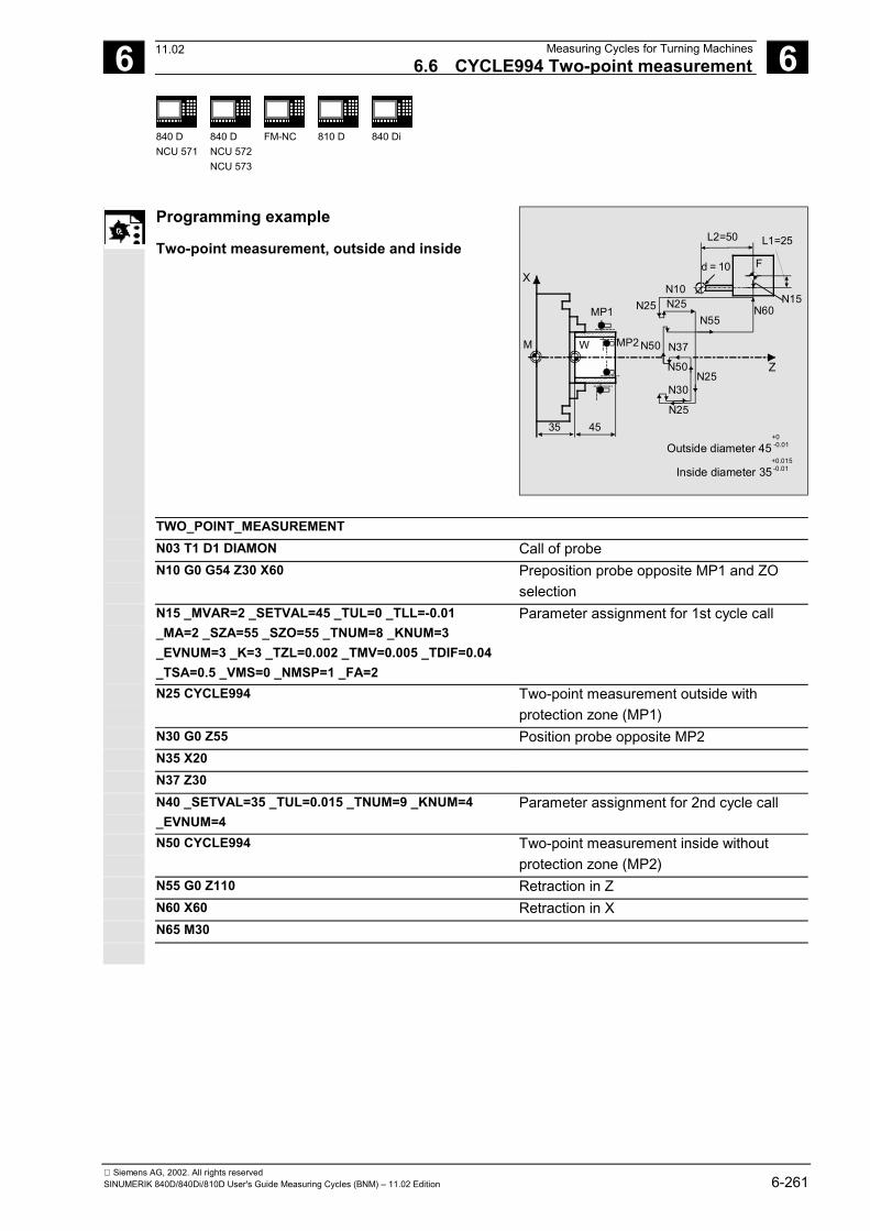
6 12.97 Measuring Cycles for Turning Machines6.6 CYCLE994 Two-point measurement 6
840 DNCU 571
840 DNCU 572NCU 573
FM-NC 810 D 840 Di
Siemens AG, 2002. All rights reservedSINUMERIK 840D/840Di/810D User's Guide Measuring Cycles (BNM) – 11.02 Edition 6-261
Programming example
Two-point measurement, outside and inside
35 45
Outside diameter 45+0-0.01
M W
MP1
MP2
X
Z
Inside diameter 35+0.015-0.01
L2=50 L1=25
F
N15
d = 10
N60
N10N25 N25
N55
N50 N37
N50N25
N30
N25
TWO_POINT_MEASUREMENTN03 T1 D1 DIAMON Call of probeN10 G0 G54 Z30 X60 Preposition probe opposite MP1 and ZO
selectionN15 _MVAR=2 _SETVAL=45 _TUL=0 _TLL=-0.01_MA=2 _SZA=55 _SZO=55 _TNUM=8 _KNUM=3_EVNUM=3 _K=3 _TZL=0.002 _TMV=0.005 _TDIF=0.04_TSA=0.5 _VMS=0 _NMSP=1 _FA=2
Parameter assignment for 1st cycle call
N25 CYCLE994 Two-point measurement outside withprotection zone (MP1)
N30 G0 Z55 Position probe opposite MP2N35 X20N37 Z30N40 _SETVAL=35 _TUL=0.015 _TNUM=9 _KNUM=4_EVNUM=4
Parameter assignment for 2nd cycle call
N50 CYCLE994 Two-point measurement inside withoutprotection zone (MP2)
N55 G0 Z110 Retraction in ZN60 X60 Retraction in XN65 M30
11.02
6 Measuring Cycles for Turning Machines 12.976.7 Complex example for workpiece measurement 6
840 DNCU 571
840 DNCU 572NCU 573
FM-NC 810 D 840 Di
Siemens AG, 2002. All rights reserved6-262 SINUMERIK 840D/840Di/810D User's Guide Measuring Cycles (BNM) – 11.02 Edition
6.7 Complex example for workpiece measurement(CYCLE973, CYCLE974)
Explanation
The workpiece shown in the figure is to be measuredwith a probe.
L2=50
L1=25N15
Fd = 10
N30
Reference groove forcalibrating the probe
N60
N55 N65N80
N85
N100N110
N105
N125
N130
Z
50
140 120
Spin-dlechuck
MP1
MP2
∅ 260
∅ 200 -0.01
∅ 150 -0.003+0.005
MP3
MP4
70 50 0.01±ÿ
100 0.01±ÿ
Workpiece
X
M
W
N20
N35 N36
N135
11.02
6 12.97 Measuring Cycles for Turning Machines6.7 Complex example for workpiece measurement 6
840 DNCU 571
840 DNCU 572NCU 573
FM-NC 810 D 840 Di
Siemens AG, 2002. All rights reservedSINUMERIK 840D/840Di/810D User's Guide Measuring Cycles (BNM) – 11.02 Edition 6-263
Programming example
Calibrate workpiece probe, measure workpiecewith CYCLE973 and CYCLE974
PART_1_MEASUREMENT
N05 T1 D1 DIAMON Select probeN06 SUPA G0 X300 Z150 Approach starting position in X and Z, from
which it is possible to approach thereference groove for calibration withoutcollision
N10 _MVAR=13 _MA=1 _MD=1 _CALNUM=1 _TZL=0_TSA=1 _PRNUM=1 _VMS=0 _NMSP=1 _FA=1
Parameters for calibration in referencegroove
N20 CYCLE973 Calibrate probe in the minus directionN25 _MA=2 Other measuring axisN30 CYCLE973 Calibrate probe in the minus directionN35 G54 G0 Z40N36 X220
Select zero offset and position probeopposite measuring point 1
N40 _MVAR=0 _SETVAL=200 _TUL=0 _TLL=-0.01_MA=2 _KNUM=8 _TNUM=3 _K=2 _TZL=0.002_TMV=0.005 _TDIF=0.2 _TSA=0.3 _PRNUM=1
Define parameters for measurement
N55 CYCLE974 Measure MP1N60 G0 Z70 Position probe opposite MP2N65 X175N70 _MA=1 _SETVAL=50 _TUL=0.01 _KNUM=9_TNUM=4
Define parameters for measurement inanother axis
N80 CYCLE974 Measure MP2N85 G0 Z180 Position probe opposite MP3N90 _MA=2 _SETVAL=150 _TUL=0.005 _TLL=-0.003_KNUM=1 _TNUM=5
Define parameters for measurement
N100 CYCLE974 Measure MP3N105 G0 Z150 Position probe opposite MP4N110 X50N115 _MA=1 _SETVAL=100 _TUL=0.01 _TLL=-0.01_KNUM=2 _TNUM=6
Define parameters for measurement
N125 CYCLE974 Measure MP4N130 G0 SUPA Z250 Retraction in ZN135 SUPA X280 Retraction in XN140 M30
�
11.02
6 Measuring Cycles for Turning Machines 12.976.7 Complex example for workpiece measurement 6
840 DNCU 571
840 DNCU 572NCU 573
FM-NC 810 D 840 Di
Siemens AG, 2002. All rights reserved6-264 SINUMERIK 840D/840Di/810D User's Guide Measuring Cycles (BNM) – 11.02 Edition
Notes
7 05.98 Miscellaneous Functions 7
Siemens AG, 2002. All rights reservedSINUMERIK 840D/840Di/810D User's Guide Measuring Cycles (BNM) – 11.02 Edition 7-265
Miscellaneous Functions
7.1 Logging of measuring results ........................................................................................ 7-2667.1.1 Storing the log ........................................................................................................ 7-2667.1.2 Handling of log cycles ............................................................................................ 7-2677.1.3 Selecting the log contents ...................................................................................... 7-2697.1.4 Log format.............................................................................................................. 7-2717.1.5 Log header ............................................................................................................. 7-2727.1.6 Variable for logging ................................................................................................ 7-2737.1.7 Example of measuring result log ........................................................................... 7-274
7.2 Cycle support for measuring cycles .............................................................................. 7-2767.2.1 Files for cycle support ............................................................................................ 7-2777.2.2 Loading the cycle support ...................................................................................... 7-2777.2.3 Assignment of calls and measuring cycles ............................................................ 7-2787.2.4 Description of parameterization cycles .................................................................. 7-279
7.3 Measuring cycle support in the program editor (≥ SW 6.2)........................................... 7-2907.3.1 Menus, cycle explanation....................................................................................... 7-2907.3.2 New functions of the input forms ........................................................................... 7-2917.3.3 GUD variables for adaptation of measuring cycle support..................................... 7-297
11.02
7 Miscellaneous Functions 05.987.1 Logging of measuring results 7
840 DNCU 571
840 DNCU 572NCU 573
810 D
Siemens AG, 2002. All rights reserved7-266 SINUMERIK 840D/840Di/810D User's Guide Measuring Cycles (BNM) – 11.02 Edition
7.1 Logging of measuring results
In SW 4.3 and higher, the standard measuring cyclessupport logging of measuring results in a file in thecontrol.
There are no special hardware requirements for loggingmeasurement results. It is executed solely by thesoftware.
7.1.1 Storing the log
Function
The log file is stored in the directory where the callingprogram is located. You can specify the file name forthe log file. The restrictions that apply to programnames also apply here. So, only letters, numbers andunderscores are permitted, and the name mustcommence with two letters or a letter followed by anunderscore. The file always has the extension "MPF".
The maximum length of the log file is set in MD 11420.If the system detects during writing that a data record istoo long, another log file is automatically created.Underscore and a digit are added to the name specifiedin _PROTNAME[1] and the message"New log file has been created" output.
In this way, up to 10 subsequent logs can be stored inthe control.After the 10th log operation is halted and the message"Please specify new log name" output.After restart, operation is continued. If a log file with thesame name already exists before logging is started,then it is deleted before writing is started.
09.01
7 05.98 Miscellaneous Functions7.1 Logging of measuring results 7
840 DNCU 571
840 DNCU 572NCU 573
810 D
Siemens AG, 2002. All rights reservedSINUMERIK 840D/840Di/810D User's Guide Measuring Cycles (BNM) – 11.02 Edition 7-267
7.1.2 Handling of log cyclesFunction
The log is enabled and disabled via the program(CYCLE100/CYCLE101). This requires a cycle callwithout setting any parameters.After disabling the log function, the log files must beunloaded from the part program memory ("Partprogram" directory) (MMC 102/103) or read out viaRS-232-C.
Print out the log file in• Word or WordPad (Courier font)• WINDOWS 95 editor• MS DOS editor
Procedure
When used with the measuring cycles, it is sufficientto activate and deactivate the logging withCYCLE100 and CYCLE101 respectively. Logging iscarried out with the parameters described inSubsections 7.1.3 to 7.1.5.The logging sequence is implemented in CYCLE105,CYCLE106, CYCLE113 and CYCLE118. These cyclesare called internally in the context of measuring cycles.
The log cycles may be used independently of themeasuring cycles. CYCLE100 and CYCLE101, andCYCLE105 and CYCLE106 are called explicitly inthis context. CYCLE113 and CYCLE118 are calledinternally. You can also call them separately forother purposes.
CYCLE100 Log ONAfter the log is enabled, an existing file with thespecified name is automatically deleted in thecontrol. All follow-up logs with _PROTNAME[1]_digitare only deleted when the preceding logs overflow.The log is reopened and the header is entered. Theinternal status variables are set.
08.99
7 Miscellaneous Functions 05.987.1 Logging of measuring results 7
840 DNCU 571
840 DNCU 572NCU 573
810 D
Siemens AG, 2002. All rights reserved7-268 SINUMERIK 840D/840Di/810D User's Guide Measuring Cycles (BNM) – 11.02 Edition
CYCLE101 Log OFFDisables the logging function and resets the internalflag.
CYCLE105(int par1) Generate log contentsThis cycle generates up to 4 lines of log contents(lines of values) according to the entries in the GUDvariables.It allows you to generate only value lines or only the logheader depending on the setting for par1.Transfer parameters: 0 output value block
1 output header
CYCLE106(int par1)Log sequential controllerThis cycle controls how logging is executed.Transfer parameters: 1 output header
2 output value block.
The cycle is called by CYCLE100 automatically whenthe log is activated. It deletes all old log files with thesame name as required, creates follow-up log files andmonitors the page layout of the log.
CYCLE113(int par1,string[10] par2)Read time and date from systempar1 = 1 Read date and return it in par2par1 = 2 Read time and return it in par2
CYCLE118(real par1,int par2,string[12] par3, intpar4, int par5)This cycle formats the numerical values according tothe places after the decimal point specified inparameter_DIGIT.par1 Real value which is to be formattedpar2 Number of decimal placesString[12] par3 Formatted return valuepar4 Control valuepar5 Set to 0
08.99
7 05.98 Miscellaneous Functions7.1 Logging of measuring results 7
840 DNCU 571
840 DNCU 572NCU 573
810 D
Siemens AG, 2002. All rights reservedSINUMERIK 840D/840Di/810D User's Guide Measuring Cycles (BNM) – 11.02 Edition 7-269
7.1.3 Selecting the log contents
Function
The measurement result log contains parts that arefixed and some that can be set. It always contains:• Measuring cycle• Measurement variant (cycle name, value of _MVAR)
The following additional data can be included in a log:• Time (specification _TIME)• Axis names of the corresponding measuring axes• Specification _AXIS:
The axis name is entered automatically according tothe measuring axis entered in _MA.
• Specification _AXIS1...3:- AXIS: Axis name of abscissa in selected plane- AXIS: Axis name of ordinate in selected plane- AXIS: Axis name of applicate in selected plane
• All result data provided by the measuring cycle in the_OVR field.
• R parameters• Comment texts
The logging values to be selected must correspond tothe measuring cycle and the selected measurementvariant. This makes for versatile adaptation of thecontents of the log to meet your requirements.
08.98
7 Miscellaneous Functions 05.987.1 Logging of measuring results 7
840 DNCU 571
840 DNCU 572NCU 573
810 D
Siemens AG, 2002. All rights reserved7-270 SINUMERIK 840D/840Di/810D User's Guide Measuring Cycles (BNM) – 11.02 Edition
Procedure
Specification of the log contents is conducted via thevariable _PROTVAL[ ].The strings stored in _PROTVAL[0] and _PROTVAL[1]are used as header lines for the log (see example inSubsection 6.1.7, Lines 8 – 10)._PROTVAL[2] ... [5] specify the line contents ofthe individual log lines.
If you change the measuring cycle or the measurementvariant, you may have to adapt _PROTVAL[2] ...[5] (see example in Subsection 6.1.7).
Up to 4 lines can be defined.You can log the• R parameters,• _OVR[],• axis names,• times,• free comments and• strings saved in _TXT[] (GUD6). Commas are used as separators.
Example_PROTVAL[2]="R27,_OVR[0],_OVR[4],_OVR[8],_OVR[12],_OVR[16],_TIME"_PROTVAL[3]="_AXIS,_OVR[1],_OVR[5],_OVR[9],_OVR[13],_OVR[17], INCH"_PROTVAL[4]="_AXIS,_OVR[2],_OVR[6],_OVR[10],_OVR[14],_OVR[18], Metro"
In this example R27 stands for a variable freely entered into the log. The texts "INCH" and "Metro"at the end of the second and third line are examples for comment texts. This makes it easy, forexample, to append dimensions after the measurement results.Logging of variables always has priority, i.e. when specified format limits are exceeded they aremodified and an alarm without terminating execution is generated.
7 05.98 Miscellaneous Functions7.1 Logging of measuring results 7
840 DNCU 571
840 DNCU 572NCU 573
810 D
Siemens AG, 2002. All rights reservedSINUMERIK 840D/840Di/810D User's Guide Measuring Cycles (BNM) – 11.02 Edition 7-271
7.1.4 Log format
Programming
The following values can be specified for the logformat:_PROTFORM[0] Number of line per page with log header_PROTFORM[1] Number of characters per line_PROTFORM[2] First page number_PROTFORM[3] Number of header lines_PROTFORM[4] Number of value lines in the log_PROTFORM[5] Column width/variable column width_PROTSYM[0] Separators between the values in the log_PROTSYM[1] Special characters for identification when
tolerance limits are exceeded_DIGIT Number of decimal places
Explanation
The number of decimal places can be set via thevariable _DIGIT in GUD6 (display precision).
The value set in parameter _PROTFORM[0]determines when a log header with title lines isoutput again. If this parameter is set to zero, the logonly contains a header at the beginning.
Default settings exist for all these parameters whichare set when the GUD modules are read in (seeSubsection 6.1.6).
The value of parameter _PROTFORM[5] determines thecolumn width of the log. If the parameter=0, the columnwidth of each column is derived from the string lengths(number of characters between the commas) of the 1stheader line (_PROTVAL[0]). This makes it possible toindividually define the width of each column. If thevalue>0, each column is formatted to this value if thestring length allows it.
08.98
7 Miscellaneous Functions 05.987.1 Logging of measuring results 7
840 DNCU 571
840 DNCU 572NCU 573
810 D
Siemens AG, 2002. All rights reserved7-272 SINUMERIK 840D/840Di/810D User's Guide Measuring Cycles (BNM) – 11.02 Edition
7.1.5 Log header
Function
The log header can be customized by the operatoror a log header prepared by the standard measuringcycles can be used.
Procedure
The header is selected via the measuring cycle databit _CBIT[11]. However, the standard log alsoallows you to customize up to three lines.
The contents of the header are stored in an array ofstring variables _HEADLINE[10], which areautomatically output when logging (CYCLE100) isenabled. The maximum number of header lines can bechanged during measuring cycle start-up(_PROTFORM[3]).
Each field element contains a line for the log header.
Explanation
Customized log headerThe contents of the string array _HEADLINE[ ] areentered in line 1 ff. The number of header lines can bedefined by the user (according to the length of the_HEADLINE array).
Predefined log headerAll variable parts are in bold formatting, that is:Page number, program name,Line 5, 6, 7 (_HEADLINE[0-2]) ff. andLine 9 (_PROTVAL[0])Line 10 (_PROTVAL[1])
7 05.98 Miscellaneous Functions7.1 Logging of measuring results 7
840 DNCU 571
840 DNCU 572NCU 573
810 D
Siemens AG, 2002. All rights reservedSINUMERIK 840D/840Di/810D User's Guide Measuring Cycles (BNM) – 11.02 Edition 7-273
Line 1 Date: 98/09/15 Time: 10:05:30 Page: 1Line 2
Line 3 Program: MEASPROGRAM_1Line 4
Line 5 Part number: 123456789Line 6 Job number: 6878Line 7 Supervised by: Smith Tel.: 1234Line 8 -----------------------------------------------------------------------------------------Line 9 Measuring , Axis , Set , Actual , Difference , TimeLine 10 point value valueLine 11 ----------------------------------------------------------------------------------------
When filling in the standard log header shown abovethe following program lines must be inserted in the mainprogram before the measuring cycle is called:DEF INT PARTNUM, JOBNUM_CBIT[11]=0 ;Log with default headerPARTNUM=123456789 JOBNUM=6878 _PROTNAME[0]="MEASPROGRAM_1"_PROTNAME[1] ="MY_LOG1"_HEADLINE[0]="Part number: "<<PARTNUM
_HEADLINE[1]="Job number:"<<JOBNUM
_HEADLINE[2]="Supervisor: Smith Tel.: 1234"_PROTVAL[0]="Measurement , Axis , Set , Actual value , Difference , Time"
_PROTVAL[1]="point , , value
7.1.6 Variable for logging
In the measuring cycle, data logging is controlled viathe following data bit:_CBIT[11]= 0 Standard log header
1 User-defined log header
The following variables describe the contents of the measurement log:Variable Type Default value Contents_PROTNAME[2] STRING[32] Blank string _PROTNAME[0] = Name of the main program from
which the log is written"SMC:PROT” _PROTNAME[1] = Name of the log file
_HEADLINE[6] STRING[80] Blank string _HEADLINE[0] ... _HEADLINE[5]
The user can enter customized texts in these strings; theyare included in the log
12.98
7 Miscellaneous Functions 05.987.1 Logging of measuring results 7
840 DNCU 571
840 DNCU 572NCU 573
810 D
Siemens AG, 2002. All rights reserved7-274 SINUMERIK 840D/840Di/810D User's Guide Measuring Cycles (BNM) – 11.02 Edition
_PROTFORM[6] INTEGER 60 _PROTFORM[0] = Number of lines per page80 _PROTFORM[1] = Number of characters per line1 _PROTFORM[2] = First page number5 _PROTFORM[3] = Number of header lines4 _PROTFORM[4] = Number of value lines in the log12 _PROTFORM[5] = Number of characters per column
_PROTSYM[2] CHAR " ; " _PROTSYM[0] = Separators between the values inthe log
" # " _PROTSYM[1] = Special characters for identificationwhen tolerance limits are exceeded
_PROTVAL[13] String[80] See _PROTVAL[0] = Contents of the header line (line 9)Example _PROTVAL[1] = Contents of the header line (line 10)
_PROTVAL[2]...[5] = Specification of the values tobe logged in successive lines
7.1.7 Example of measuring result log
Line 1 Date: 96/11/15 Time: 10:05:30 Page: 1Line 2
Line 3 Program: MEASPROGRAM_1Line 4
Line 5 Part number: 123456789Line 6 Job number: 6878Line 7 Supervised by: Smith Tel.: 1234Line 8 -----------------------------------------------------------------------------------------Line 9 Measuring , Axis , Set , Actual , Difference , TimeLine 10 point value valueLine 11 ----------------------------------------------------------------------------------------Line 12 CYCLE978 , _MVAR , 100
Line 13 1 , Z , 80.000 , 79.987 , -0.013 , 09:35,12
Line 14
Line 15
Line 16 CYCLE977 , _MVAR , 102
Line 17 2 , X , 64.000 , 64.009 , 0.009 , 09:36,45
Line 18 , Y , 38.000 , 37.998 , -0.002 , 09:37,35
Programming
The log shown above is created using the followingprogram.The example shows the user how to handle the log.
08.99
7 05.98 Miscellaneous Functions7.1 Logging of measuring results 7
840 DNCU 571
840 DNCU 572NCU 573
810 D
Siemens AG, 2002. All rights reservedSINUMERIK 840D/840Di/810D User's Guide Measuring Cycles (BNM) – 11.02 Edition 7-275
%_N_MEASPROGRAM_1_MPF;$PATH=/_N_MPF_DIR;Measure ring inside and outside with measurement logDEF INT PARTNUM, JOBNUM; ----------- Set parameters for log -----------------_CBIT[11]=0 ;Log with default header; -------------------------- Log header ------------------------
PARTNUM=123456789 JOBNUM=6878_PROTNAME[0]="MEASPROGRAM_1"
;Name of calling program
_PROTNAME[1] ="MY_LOG1" ;Name of log file_HEADLINE[0]="Part number: "<<PARTNUM_HEADLINE[1]="Job number:"<<JOBNUM
_HEADLINE[2]="Supervisor: Smith Tel.: 1234"; ---------------------- Log format ---------------------- Formats: Default values from GUD5_PROTSYM[0] =" , " _PROTSYM[1] = " * " ;Define separators and special characters_PROTFORM[4]=2 ;Two value lines; ---------------------- Log contents ----------------------; Header lines_PROTVAL[0]="Measurement , Axis , Set , Actual value , Difference_PROTVAL[1]="point , , value"
; ---------------- Other value assignments -----------------R27=1 ;Assign counter for measurement log; -------- Perform measurements with log -------------N100 G0 G17 G90 T3 D1 Z100 F1000 ;Approach start position for measurementN110 X70 Y90;_MVAR=100 _SETVAL=80 _MA=3 _TSA=2 _FA=2 ;Set measuring cycle parameters... ;Measurement variant: Measure surface with; Contents of the value lines_PROTVAL[2]="R27,_AXIS,_OVR[0],_OVR[4],_OVR[16],_TIME"
N150 CYCLE100 ;Activate logN160 CYCLE978 ;Measure surfaceN170 Z200 ;Retraction in ZN180 X64 Y38 ;Position above shaft centerN185 Z130 ;Lower in Z;_MVAR=102 _SETVAL=70 _FA=2 _TSA=2 _ID=-20 ;Set measuring cycle parameters... ;Measurement variant: Measure shaft with ZO_PROTVAL[2]="R27,_AXIS1,_OVR[1],_OVR[5],_OVR[17],_TIME"_PROTVAL[3]=" ,_AXIS2,_OVR[2],_OVR[6],_OVR[18],_TIME"
R27=R27+1 ;Increase user-def. counter forN190 CYCLE977 ;Measure shaftN210 CYCLE101 ;Deactivate logN220 Z200 ;Retraction in ZN290 M2
10.00
7 Miscellaneous Functions 05.987.2 Cycle support for measuring cycles 7
840 DNCU 571
840 DNCU 572NCU 573
810 D
Siemens AG, 2002. All rights reserved7-276 SINUMERIK 840D/840Di/810D User's Guide Measuring Cycles (BNM) – 11.02 Edition
7.2 Cycle support for measuring cycles
Function
In SW 4.3 and higher, cycle support for measuringcycles in the ASCII editor is provided as for thestandard cycles.With this support function, the parameters described asmandatory parameters are input for each measuringcycle. For the additional parameters the last valuesinput are retained. Furthermore, it is possible to changethe additional parameters.
The measuring cycles are selected in the editor byusing the vertical soft keys. The soft key bar is dividedaccording to measuring tasks, e.g. "Calibrate" and"Calibrate in hole" or "Tool probe". In this manner thereis no 1:1 assignment between the soft keys and themeasuring cycles.
In MMC SW 5 and higher, measuring cycle supportis provided by the soft keys>
→ Support
→ Newcycle →
Measuringcycles
in the extension menu of the editor.
In the edited program there are calls with parameter list,e.g.CYCLE_976(...) for calibrating in hole,CYCLE_CAL_TOOLSETTER(...) for calibrating the toolprobe.
06.00
7 05.98 Miscellaneous Functions7.2 Cycle support for measuring cycles 7
840 DNCU 571
840 DNCU 572NCU 573
810 D
Siemens AG, 2002. All rights reservedSINUMERIK 840D/840Di/810D User's Guide Measuring Cycles (BNM) – 11.02 Edition 7-277
7.2.1 Files for cycle support
Function
Measuring cycle support requires the following files:• cov.com
Configuring the soft keys for cycle selection• sc.com
Configuring the input screens for the individualparameters
• Auxiliary cycle*.spfAdditional cycles with parameter list, which transferthe input parameters to the measuring cycle GUDvariables and call the measuring cycles.
These files are combined in the following twoarchives on the measuring cycle diskette:• mcsupp_1.com• mcsupp_2.com.
7.2.2 Loading the cycle support
Function
The files mcsupp_1.com and mcsupp_2.com areloaded from diskette or via RS-232-C (V24) with"Data in" into the "Services" menu.
With the MMC 102/103 the auxiliary cycle programs(see list Subsection 6.2.3) must be transferred to theNCU with "Load".
The Power ON is executed.
7 Miscellaneous Functions 05.987.2 Cycle support for measuring cycles 7
840 DNCU 571
840 DNCU 572NCU 573
810 D
Siemens AG, 2002. All rights reserved7-278 SINUMERIK 840D/840Di/810D User's Guide Measuring Cycles (BNM) – 11.02 Edition
7.2.3 Assignment of calls and measuring cycles
Function
The following table provides an overview of:Measuring task, Measuring Cycle, Call
Measuring task, function Measuringcycle
Call in the program
Calibrate tool probe CYCLE971,CYCLE972,CYCLE982
CYCLE_CAL_TOOLSETTER(...)
Calibrating a workpiece probe on surface CYCLE973,CYCLE976
CYCLE_CAL_PROBE(...)
Calibrate workpiece probe in reference groove CYCLE973 CYCLE_973(...)Calibrate workpiece probe in hole CYCLE976 CYCLE_976(...)Measure milling tool on milling machines CYCLE971 CYCLE_971(...)Measure turning tool CYCLE972 CYCLE_972(...)Measure turning and milling tools on turningmachines (measuring cycles SW 5.4 andhigher)
CYCLE982 CYCLE_982(...)
Measure hole/shaft parallel to axis/at an angle CYCLE977,CYCLE979
CYCLE_977_979A(...)
Measure groove/web parallel to axis/at an angle CYCLE977,CYCLE979
CYCLE_977_979B(...)
Measure rectangle inside/outside parallel toaxis
CYCLE977 CYCLE_977_979C(...)
Single-point measurement milling machine CYCLE978 CYCLE_978(...)Angle measurement CYCLE998 CYCLE_998(...)Measure corner CYCLE961 CYCLE_961_W
CYCLE_961_PSingle-point measurement turning CYCLE974 CYCLE_974(...)Two-point measurement CYCLE994 CYCLE_994(...)Additional parameters - CYCLE_PARA(...)
06.00
7 05.98 Miscellaneous Functions7.2 Cycle support for measuring cycles 7
840 DNCU 571
840 DNCU 572NCU 573
810 D
Siemens AG, 2002. All rights reservedSINUMERIK 840D/840Di/810D User's Guide Measuring Cycles (BNM) – 11.02 Edition 7-279
7.2.4 Description of parameterization cycles
Function
The individual parameterization cycles of the measuringcycles together with their input parameters aredescribed below.The parameter names in the table directly refer to thedefining parameters of the measuring cycle in questionin the GUD variables. If no parameter is given, it is aselection field in the input screenform for particularfunctions.
Calibrating in hole – CYCLE_976
With CYCLE_976
Soft keys Measurem.milling →
Probecalibrat.
CYCLE976 can be parameterized to calibrate areference hole.
Parameters
_SETVAL REAL Setpoint INTEGER Selection: Angular position
0...Paraxial calibration/1...calibration at an angle INTEGER Selection: Positional deviation
0...without/1...with specification of positional deviation INTEGER Selection: Number of axes
Number of axes to be calibrated, 1, 2 or 4 INTEGER Selection: Ball calculation
0...without/1...with calculation of probe ball diameter _MA INTEGER Number of measuring axis _MD INTEGER Determining the measuring direction
0...in positive direction/1...in negative direction _STA1 REAL Angle _PRNUM INTEGER Probe number Selection: Hole type
0... hole center known/1...unknown
11.02
7 Miscellaneous Functions 05.987.2 Cycle support for measuring cycles 7
840 DNCU 571
840 DNCU 572NCU 573
810 D
Siemens AG, 2002. All rights reserved7-280 SINUMERIK 840D/840Di/810D User's Guide Measuring Cycles (BNM) – 11.02 Edition
Calibration in groove – CYCLE_973
With CYCLE_973
Soft keys Measurem.turning →
Probecalibrat.
CYCLE973 can be parameterized to calibrate areference groove.
Parameters
_SETVAL REAL Setpoint INTEGER Selection: Positional deviation
0...without/1...with specification of positional deviation INTEGER Selection: Number of axes
Number of axes to be calibrated, 1, 2 INTEGER Selection: Ball calculation
0...without/1...with calculation of probe ball diameter _MA INTEGER Number of measuring axis _MD INTEGER Determining the measuring direction
0...in positive direction/1...in negative direction _CALNUM INTEGER Selection of calibration groove with number _PRNUM INTEGER Probe number
Calibration on surface – CYCLE_CAL_PROBE
With CYCLE_CAL_PROBE
Soft keys Measurem.turning →
Probecalibrat. →
Plane
or
Soft keys Measurem.milling →
Probecalibrat. →
Plane
measuring cycles CYCLE973 and 976 can beparameterized to calibrate a surface.
Parameters
INTEGER Selection: Cycle number 976... for CYCLE976 (milling machine),973... for CYCLE973 (turning machine)
_SETVAL REAL Calibration setpoint with respect to workpiece zero _MA INTEGER Number of measuring axis _MD INTEGER Measurement direction _PRNUM INTEGER Probe number _MVAR INTEGER Selection: Measuring variant (for CYCLE976 only)
0: Calibration on any surface 10000: Calibration in 3rd axis with calculation of probe length.
11.02
7 05.98 Miscellaneous Functions7.2 Cycle support for measuring cycles 7
840 DNCU 571
840 DNCU 572NCU 573
810 D
Siemens AG, 2002. All rights reservedSINUMERIK 840D/840Di/810D User's Guide Measuring Cycles (BNM) – 11.02 Edition 7-281
Calibrating a tool measuring probe –CYCLE_CAL_TOOLSETTER
With CYCLE_CAL_TOOLSETTER
Soft keys Measurem.turning →
Calibrat.TL probe (CYCLE971)
or
Soft keys Measurem.milling →
Calibrat.TL probe (CYCLE982)
measuring cycles CYCLE971, 972 and CYCLE982 can beparameterized to calibrate a tool measuring probe.
Parameters
INTEGER Selection: Cycle number 971... for CYCLE971 (milling machine),972... for CYCLE972 (turning machine)982... for CYCLE982 (turning machine, turning and milling tools)
_MA INTEGER Number of measuring axis and for CYCLE972 also the offset axis _PRNUM INTEGER Probe number INTEGER only for CYCLE971
Selection: Measurement variant0...absolute calibration/1...incremental calibration
_FA REAL Measuring path
Measuring turning tools – CYCLE_972
CYCLE_972 can be used to parameterize CYCLE976to gauge tools.No longer parameterized by new measuring cyclesupport in measuring cycles SW 6.2 and higher.
Parameters
_MA INTEGER Number of measuring axis
11.02
7 Miscellaneous Functions 05.987.2 Cycle support for measuring cycles 7
840 DNCU 571
840 DNCU 572NCU 573
810 D
Siemens AG, 2002. All rights reserved7-282 SINUMERIK 840D/840Di/810D User's Guide Measuring Cycles (BNM) – 11.02 Edition
Measuring milling tools – CYCLE_971
With CYCLE_971
Soft keys Measurem.milling →
Toolmeasurem.
CYCLE971 can be parameterized for tool measurement.
Parameters
_MVAR INTEGER Measurement variant _MA INTEGER Number of measuring axis _ID REAL Offset _PRNUM INTEGER Probe number _MFS[0] REAL Feed 1st probing (only with _CBIT[12]=1) _MFS[1] REAL Speed 1st probing _MFS[2] REAL Feed 2nd probing _MFS[3] REAL Speed 2nd probing _MFS[4] REAL Feed 3rd probing _MFS[5] REAL Speed 3rd probing
Tool measurement turning and milling tools forturning machines – CYCLE_982 (measuring cyclesSW 5.4 and higher)
With CYCLE_982
Soft keys Measurem.turning →
Toolmeasurem.
CYCLE982 can be parameterized for tool measurement.
Parameters
_MVAR INTEGER Measurement variant _MA INTEGER Number of measuring axis _STA1 REAL Starting angle on milling tools _CORA REAL Offset angular position after reversal for milling tools
11.02
7 05.98 Miscellaneous Functions7.2 Cycle support for measuring cycles 7
840 DNCU 571
840 DNCU 572NCU 573
810 D
Siemens AG, 2002. All rights reservedSINUMERIK 840D/840Di/810D User's Guide Measuring Cycles (BNM) – 11.02 Edition 7-283
Measuring a shaft hole – CYCLE_977_979A
With CYCLE_977_979A
Soft keys Measurem.milling →
Toolmeasurem. →
HoleShaft
measurement variants xxx1 and xxx2 of measuringcycles CYCLE977 and CYCLE979 can beparameterized.
Parameters
INTEGER Selection: Angular position 977...paraxial measurement / 979...measurement at an angle
_MVAR INTEGER Measurement variant _SETVAL REAL Setpoint _ID REAL Infeed path _SZA REAL Protection zone _TNUM REAL Measurement only:
Tool number for automatic offset _TNAME STRING Alternatively, measurement only:
Tool name with active tool management _KNUM INTEGER Offset number
D number for measurement / ZO number for calculating zero offset _CPA REAL Center 1st axis _CPO REAL Center 2nd axis _STA1 REAL Initial angle _INCA REAL Indexing angle _PRNUM INTEGER Measuring probe number
CYCLE979 only:The number of measuring points is assigned from the thousands digit; 0... 3 measuring points, 1... 4 measuring points
11.02
7 Miscellaneous Functions 05.987.2 Cycle support for measuring cycles 7
840 DNCU 571
840 DNCU 572NCU 573
810 D
Siemens AG, 2002. All rights reserved7-284 SINUMERIK 840D/840Di/810D User's Guide Measuring Cycles (BNM) – 11.02 Edition
Measure groove web – CYCLE_977_979B
With CYCLE_977_979B
Soft keys Measurem.milling →
Toolmeasurem. →
Slot orweb
measurement variants xxx3 and xxx4 of measuringcycles CYCLE977 and CYCLE979 can beparameterized.
Parameters
INTEGER Selection: Angular position 977...paraxial measurement / 979...measurement at an angle
_MVAR INTEGER Measurement variant _SETVAL REAL Setpoint _ID REAL Infeed path _MA INTEGER Number of measuring axis _TNUM REAL Measurement only:
Tool number for automatic offset _TNAME STRING Alternatively, measurement only:
Tool name with active tool management _KNUM INTEGER Offset number
D number for measurement / ZO number for calculating zero offset _CPA REAL Center 1st axis _CPO REAL Center 2nd axis _STA1 REAL Initial angle _SZA REAL Protection range _PRNUM INTEGER Probe number
Measure rectangle – CYCLE_977_979C
With CYCLE_977_979C
Soft keys Measurem.milling →
Toolmeasurem. →
>> →
Rectangle
measurement variants xxx5 and xxx6 of measuring cycleCYCLE977 can be parameterized.
11.02
7 05.98 Miscellaneous Functions7.2 Cycle support for measuring cycles 7
840 DNCU 571
840 DNCU 572NCU 573
810 D
Siemens AG, 2002. All rights reservedSINUMERIK 840D/840Di/810D User's Guide Measuring Cycles (BNM) – 11.02 Edition 7-285
Parameters
_MVAR INTEGER Measurement variant _SETV[0] REAL Setpoint length _SETV[1] REAL Setpoint width _ID REAL Infeed path _SZA REAL Protection zone length _SZO REAL Protection zone width _TNUM
REAL Measurement only:
Tool number for automatic offset _TNAME STRING Alternatively, measurement only:
Tool name with active tool management _KNUM INTEGER Offset number
D number for measurement / ZO number for calculating zero offset
Single point measurement – CYCLE_978
With CYCLE_978
Soft keys Measurem.milling →
Toolmeasurem. →
Plane
CYCLE978 can be parameterized.
Parameters
_MVAR INTEGER Measurement variant _SETVAL REAL Setpoint _MA INTEGER Measuring axis _TNUM REAL Measurement only:
Tool number for automatic offset _TNAME
STRING Alternatively, measurement only:
Tool name with active tool management _KNUM INTEGER Offset number
D number for measurement / ZO number for calculating zero offset
11.02
7 Miscellaneous Functions 05.987.2 Cycle support for measuring cycles 7
840 DNCU 571
840 DNCU 572NCU 573
810 D
Siemens AG, 2002. All rights reserved7-286 SINUMERIK 840D/840Di/810D User's Guide Measuring Cycles (BNM) – 11.02 Edition
Angle measurement – CYCLE_998
With CYCLE_998
Soft keys Measurem.milling →
Toolmeasurem. →
Angle
CYCLE998 can be parameterized.
Parameters
_MVAR INTEGER Measurement variant _SETVAL REAL Setpoint _ID REAL Distance _RA INTEGE Number of rotary axis _MA INTEGER Number of measuring axis _KNUM INTEGER ZO number _STA1 REAL Angle _PRNUM INTEGER Probe number _MD INTEGER Determining the measuring direction
0...in positive direction / 1...in negative direction _INCA REAL Setpoint angle about 2nd axis of the plane _SETV[0] REAL Distance between measuring points P1 and P3
Corner measurement 1 – CYCLE_961_W
With CYCLE_961_W
Soft keys Measurem.milling →
Toolmeasurem. →
Corner
measurement variants 105 ... 108 for CYCLE961can be parameterized.
Parameters
INTEGER Selection: Outside or inside corner0...inside corner/1...outside corner
INTEGER Selection: Number of measuring points, 3 or 4 _SETV[0] REAL Distance between starting point and measuring point 2, without sign _SETV[1] REAL Distance between starting point and measuring point 4, without sign _ID REAL Retraction path in 3rd axis (applicate), for outside corner only,
without sign _STA1 REAL Enter approximate angle between 1st axis (abscissa) and 1st edge,
in clockwise direction with negative sign _INCA REAL Angle between 1st and 2nd edge of workpiece, in clockwise direction
with negative sign _KNUM INTEGER ZO number
11.02
7 05.98 Miscellaneous Functions7.2 Cycle support for measuring cycles 7
840 DNCU 571
840 DNCU 572NCU 573
810 D
Siemens AG, 2002. All rights reservedSINUMERIK 840D/840Di/810D User's Guide Measuring Cycles (BNM) – 11.02 Edition 7-287
_SETV[4] REAL Selection: Offset1...measured corner entered as zero point2...measured corner is entered in 1st axis offset by the value in
_SETV[2] and as a zero point3...measured corner is entered in both axes offset and as a
zero point4...measured corner is entered in 2nd axis offset by the value in
_SETV[3] and as a zero point _SETV[2] REAL For 3 measuring points only:
Offset of coordinate origin in 1st axis (abscissa) _SETV[3] REAL For 3 measuring points only:
Offset of coordinate origin in 2nd axis (ordinate) _PRNUM INTEGER Probe number
Corner measurement 2 – CYCLE_961_P
With CYCLE_961_P
Soft keys Measurem.milling →
Toolmeasurem. →
Corner
measurement variants 117 ... 118 for CYCLE961 canbe parameterized.
Parameters
INTEGER Selection: Outside or inside corner0...inside corner/1...outside corner
_ID REAL Infeed path of measuring probe to measuring height, without sign _SETV[0] REAL Starting position for measuring the 1st point in the 1st axis (abscissa) _SETV[1] REAL Starting position for measuring the 1st point in the 2nd axis (ordinate) _SETV[2] REAL Starting position for measuring the 2nd point in the 1st axis (abscissa) _SETV[3] REAL Starting position for measuring the 2nd point in the 2nd axis (ordinate) _SETV[4] REAL Starting position for measuring the 3rd point in the 1st axis (abscissa) _SETV[5] REAL Starting position for measuring the 3rd point in the 2nd axis (ordinate) _SETV[6] REAL Starting position for measuring the 4th point in the 1st axis (abscissa) _SETV[7] REAL Starting position for measuring the 4th point in the 2nd axis (ordinate) _KNUM INTEGER ZO number _PRNUM INTEGER Probe number
11.02
7 Miscellaneous Functions 05.987.2 Cycle support for measuring cycles 7
840 DNCU 571
840 DNCU 572NCU 573
810 D
Siemens AG, 2002. All rights reserved7-288 SINUMERIK 840D/840Di/810D User's Guide Measuring Cycles (BNM) – 11.02 Edition
Single-point measurement – CYCLE_974
With CYCLE_974
Soft keys Measurem.turning →
Toolmeasurem. →
1-pointmeasurem.
CYCLE974 can be parameterized.
Parameters
_MVAR INTEGER Measurement variant _SETVAL REAL Setpoint _MA INTEGER Number of measuring axis _TNUM REAL Measurement only:
Tool number for automatic offset _TNAME STRING Alternatively, measurement only:
Tool name with active tool management _KNUM INTEGER Offset number
D number for measurement / ZO number for calculating zero offset _PRNUM INTEGER Probe number _STA1 REAL Initial angle
Two-point measurement – CYCLE_994
With CYCLE_994
Soft keys Measurem.turning →
Toolmeasurem. →
Two-pointmeasurem.
CYCLE994 can be parameterized.
Parameters
_MVAR INTEGER Measurement variant _SETVAL REAL Setpoint _MA INTEGER Number of measuring axis _TNUM REAL Measurement only:
Tool number for automatic offset _TNAME STRING Alternatively, measurement only:
Tool name with active tool management _KNUM INTEGER Offset number
D number for measurement / ZO number for calculating zero offset _SZA REAL Protection zone on workpiece, 1st axis (abscissa) _SZO REAL Protection zone on workpiece, 2nd axis (ordinate) _PRNUM INTEGER Probe number
11.02
7 05.98 Miscellaneous Functions7.2 Cycle support for measuring cycles 7
840 DNCU 571
840 DNCU 572NCU 573
810 D
Siemens AG, 2002. All rights reservedSINUMERIK 840D/840Di/810D User's Guide Measuring Cycles (BNM) – 11.02 Edition 7-289
Setting additional parameters – CYCLE_PARA
On measuring cycles SW 6.2 and higher, measuringcycle support no longer supports CYCLE_PARA asan autonomous cycle.If _MZ_MASK[2]=0 is set in the GUD field, theCYCLE_PARA call will be written in the NC program infront of each measuring cycle call.
Parameters
_FA REAL Measuring path in mm _VMS REAL Variable measuring velocity _NMSP INTEGER Number of measurements at the same location _RF REAL CYCLE979 only:
Feedrate at circular-path programming _PRNUM INTEGER Probe number _CORA REAL Only if monoprobe is used:
Offset angle position _TZL REAL Tolerance range for zero offset _TMV REAL Select range for offset with mean value calculation, greater than _TZL _TUL REAL Upper tolerance range workpiece, oversize acc. to drawing _TLL REAL Lower tolerance range workpiece, undersize acc. to drawing _TSA REAL Safe area for measuring result _EVNUM INTEGER Number of empirical value memory that is calculated _K REAL Weighting factor for mean value derivation _TDIF REAL Tolerance range for dimensional difference check
11.02
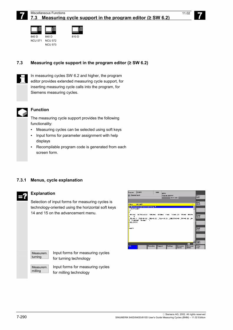
7 Miscellaneous Functions 05.987.3 Measuring cycle support in the program editor (≥ SW 6.2) 7
840 DNCU 571
840 DNCU 572NCU 573
810 D
Siemens AG, 2002. All rights reserved7-290 SINUMERIK 840D/840Di/810D User's Guide Measuring Cycles (BNM) – 11.02 Edition
7.3 Measuring cycle support in the program editor (≥ SW 6.2)
In measuring cycles SW 6.2 and higher, the programeditor provides extended measuring cycle support, forinserting measuring cycle calls into the program, forSiemens measuring cycles.
Function
The measuring cycle support provides the followingfunctionality:• Measuring cycles can be selected using soft keys• Input forms for parameter assignment with help
displays• Recompilable program code is generated from each
screen form.
7.3.1 Menus, cycle explanation
Explanation
Selection of input forms for measuring cycles istechnology-oriented using the horizontal soft keys14 and 15 on the advancement menu.
Measurem.turning
Input forms for measuring cyclesfor turning technology
Measurem.milling
Input forms for measuring cyclesfor milling technology
11.02
7 05.98 Miscellaneous Functions7.3 Measuring cycle support in the program editor (≥ SW 6.2) 7
840 DNCU 571
840 DNCU 572NCU 573
810 D
Siemens AG, 2002. All rights reservedSINUMERIK 840D/840Di/810D User's Guide Measuring Cycles (BNM) – 11.02 Edition 7-291
7.3.2 New functions of the input forms
Function
• With GUD field _MZ_MASK it is possible to adjustthe input forms for measuring cycles to technologicalconditions and user requirements (see Section7.3.3).
• In the measuring cycles, the measurement variant iscontrolled with parameter _MVAR. It often containsseveral settings encoded to form a single value. Inthe input forms of the new measuring cycle support,the separate settings are separated into differentinput fields that you can move between with thetoggle key.
• The same applies to parameter _KNUM used forencoding the offset variants
• The input form changes depending on the settings ofthe NCK-global GUD field _MZ_MASK that isdefined in module GUD6.
• The input forms change dynamically. Only thoseinput fields that are necessary for the selectedmeasurement variant or offset option are display,unnecessary input fields are hidden.
• If a form is displayed again, all fields will contain thevalues last entered as defaults.
11.02
7 Miscellaneous Functions 05.987.3 Measuring cycle support in the program editor (≥ SW 6.2) 7
840 DNCU 571
840 DNCU 572NCU 573
810 D
Siemens AG, 2002. All rights reserved7-292 SINUMERIK 840D/840Di/810D User's Guide Measuring Cycles (BNM) – 11.02 Edition
Vertical soft key menu for turning technology
Probecalibrat.
Call screen form for CYCLE973Calibrate workpiece probe for turningmachines
Toolmeasurem.
Call new vertical soft key menu for"measure workpiece"
Calibrat.TL probe
Call screen form for CYCLE982Calibrate tool probe for turning machines
Toolmeasurem.
Call screen form for CYCLE982Gauge turning and milling tools for turningmachines
<<
Jump back
Vertical soft key menu for measure workpiece,turning
1-pointmeasurem.
Call screen formWorkpiece measurement for turningmachines CYCLE974 1 point measurement
Two-pointmeasurem.
Call screen formWorkpiece measurement for turningmachines CYCLE994 2 point measurement
<<
Jump back to selection menu turning
11.02
7 05.98 Miscellaneous Functions7.3 Measuring cycle support in the program editor (≥ SW 6.2) 7
840 DNCU 571
840 DNCU 572NCU 573
810 D
Siemens AG, 2002. All rights reservedSINUMERIK 840D/840Di/810D User's Guide Measuring Cycles (BNM) – 11.02 Edition 7-293
Vertical soft key menu for milling technology
Probecalibrat.
Call screen form for CYCLE976Calibrate workpiece probe for millingmachines
Toolmeasurem.
Call new vertical soft key menu forselection "measure workpiece"
Calibrat.TL probe
Call screen form for CYCLE972Calibrate tool probe for milling machines
Toolmeasurem.
Call screen form for CYCLE972Gauge milling tools on milling machines
<<
Jump back
11.02
7 Miscellaneous Functions 05.987.3 Measuring cycle support in the program editor (≥ SW 6.2) 7
840 DNCU 571
840 DNCU 572NCU 573
810 D
Siemens AG, 2002. All rights reserved7-294 SINUMERIK 840D/840Di/810D User's Guide Measuring Cycles (BNM) – 11.02 Edition
Vertical soft key menu for workpiecemeasurement milling
HoleShaft
Call screen form for workpiecemeasurement for milling machinesCYCLE974/979 drill-hole/shaftDrill-hole/shaft and paraxial/under angleswitchover are performed in the screenform.
Slot orweb
Call screen form for workpiecemeasurement for milling machinesCYCLE974/979 slot/webSlot/web and paraxial/under angle switch-over are performed in the screen form.
Plane Call screen form for workpiecemeasurement for milling machinesCYCLE978 1 point measurement
Angle Call screen form for zero measurement formilling machines CYCLE998 anglemeasurement 1 angle/2 angle switchover isperformed in the screen form.
Corner Call screen form automatic setup cornerinternal/external CYCLE961.Switchover between corner setup specifyingdistances and angle or points is performedwithin the form
>>
Call vertical advancement menu
<<
Jump back to selection menu milling
11.02
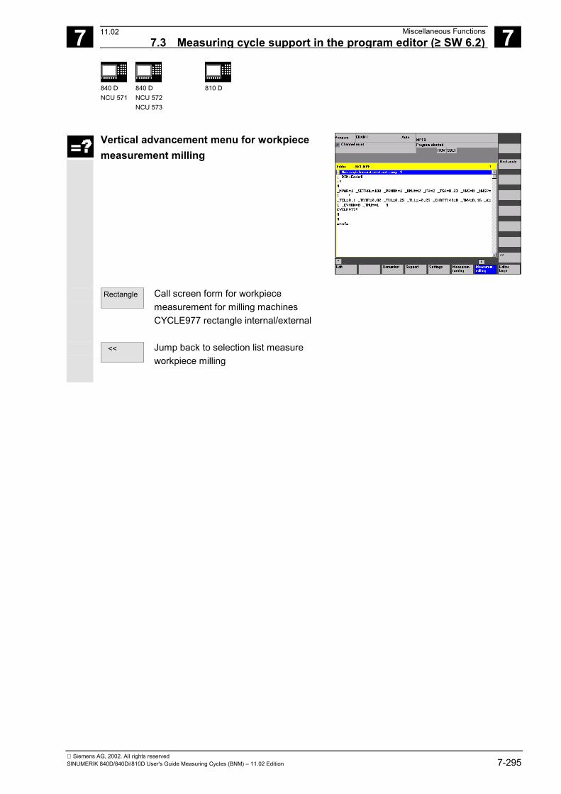
7 05.98 Miscellaneous Functions7.3 Measuring cycle support in the program editor (≥ SW 6.2) 7
840 DNCU 571
840 DNCU 572NCU 573
810 D
Siemens AG, 2002. All rights reservedSINUMERIK 840D/840Di/810D User's Guide Measuring Cycles (BNM) – 11.02 Edition 7-295
Vertical advancement menu for workpiecemeasurement milling
Rectangle Call screen form for workpiecemeasurement for milling machinesCYCLE977 rectangle internal/external
<<
Jump back to selection list measureworkpiece milling
11.02
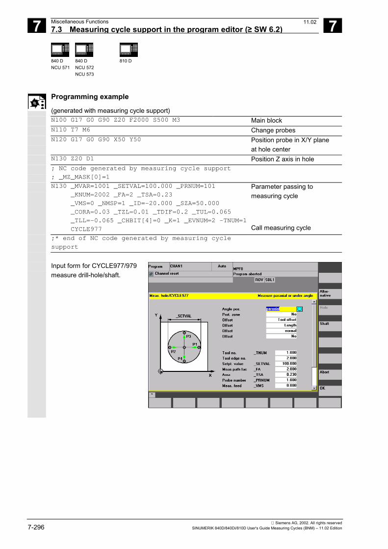
7 Miscellaneous Functions 05.987.3 Measuring cycle support in the program editor (≥ SW 6.2) 7
840 DNCU 571
840 DNCU 572NCU 573
810 D
Siemens AG, 2002. All rights reserved7-296 SINUMERIK 840D/840Di/810D User's Guide Measuring Cycles (BNM) – 11.02 Edition
Programming example
(generated with measuring cycle support) N100 G17 G0 G90 Z20 F2000 S500 M3 Main block N110 T7 M6 Change probes N120 G17 G0 G90 X50 Y50 Position probe in X/Y plane
at hole center N130 Z20 D1 Position Z axis in hole ; NC code generated by measuring cycle support
; _MZ_MASK[0]=1
N130 _MVAR=1001 _SETVAL=100.000 _PRNUM=101 _KNUM=2002 _FA=2 _TSA=0.23 _VMS=0 _NMSP=1 _ID=-20.000 _SZA=50.000 _CORA=0.03 _TZL=0.01 _TDIF=0.2 _TUL=0.065 _TLL=-0.065 _CHBIT[4]=0 _K=1 _EVNUM=2 –TNUM=1 CYCLE977
Parameter passing to measuring cycle
Call measuring cycle ;* end of NC code generated by measuring cycle
support
Input form for CYCLE977/979measure drill-hole/shaft.
11.02
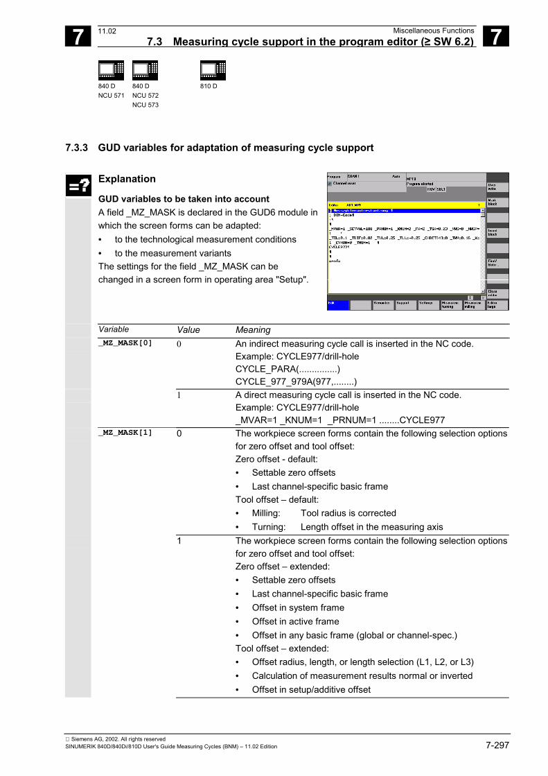
7 05.98 Miscellaneous Functions7.3 Measuring cycle support in the program editor (≥ SW 6.2) 7
840 DNCU 571
840 DNCU 572NCU 573
810 D
Siemens AG, 2002. All rights reservedSINUMERIK 840D/840Di/810D User's Guide Measuring Cycles (BNM) – 11.02 Edition 7-297
7.3.3 GUD variables for adaptation of measuring cycle support
Explanation
GUD variables to be taken into account A field _MZ_MASK is declared in the GUD6 module inwhich the screen forms can be adapted:• to the technological measurement conditions• to the measurement variantsThe settings for the field _MZ_MASK can bechanged in a screen form in operating area "Setup".
Variable Value Meaning _MZ_MASK[0] 0 An indirect measuring cycle call is inserted in the NC code.
Example: CYCLE977/drill-hole CYCLE_PARA(...............) CYCLE_977_979A(977,........)
1 A direct measuring cycle call is inserted in the NC code. Example: CYCLE977/drill-hole _MVAR=1 _KNUM=1 _PRNUM=1 ........CYCLE977
_MZ_MASK[1] 0 The workpiece screen forms contain the following selection optionsfor zero offset and tool offset: Zero offset - default:• Settable zero offsets• Last channel-specific basic frame Tool offset – default:• Milling: Tool radius is corrected• Turning: Length offset in the measuring axis
1 The workpiece screen forms contain the following selection optionsfor zero offset and tool offset: Zero offset – extended:• Settable zero offsets• Last channel-specific basic frame• Offset in system frame• Offset in active frame• Offset in any basic frame (global or channel-spec.) Tool offset – extended:• Offset radius, length, or length selection (L1, L2, or L3)• Calculation of measurement results normal or inverted• Offset in setup/additive offset
11.02
7 Miscellaneous Functions 05.987.3 Measuring cycle support in the program editor (≥ SW 6.2) 7
840 DNCU 571
840 DNCU 572NCU 573
810 D
Siemens AG, 2002. All rights reserved7-298 SINUMERIK 840D/840Di/810D User's Guide Measuring Cycles (BNM) – 11.02 Edition
_MZ_MASK[2] 0 Forms without input fields for parameters:• _VMS: Measuring velocity• _NMSP: Number of measurements at the same location The following default values are entered in the NC code for theparameters:• _VMS=0 corresponds to 150 mm/min or 5.9055 inch/min• _NMSP=1 number of measurements = 1
1 Forms with parameter input for:• _VMS: Measuring velocity• _NMSP: Number of measurements at the same location
_MZ_MASK[3] 0 Screen forms for workpiece measurement with automatic tooloffset and tool measurement do not contain an input field for thefollowing parameters:• _EVNUM: Number of empirical value memory The following default value is entered in the NC code:• _EVNUM=0
No empirical value memory is taken into account. 1 Screen forms for workpiece measurement with automatic tool
offset and tool measurement contain input fields for the followingparameters:• _EVNUM: Number of empirical value memory
_MZ_MASK[4] 0 Screen forms without input fields for the following parameters formean value calculation with automatic tool offset:• _TMV: Select range for offset with mean value calculation• _K: Weighting factor for mean value derivation• EVNUM: Mean value memory number The following default values are entered in the NC code:• _TMV=ABS(_TUL-_TLL)/3• _K=1• _EVNUM=0• _CHBIT[4]=0
1 Screen forms contain input fields for the following parameters formean value calculation with automatic tool offset:• _TMV: Select range for offset with mean value calculation• _K: Weighting factor for mean value derivation• _EVNUM: Mean value memory number• _CHBIT[4]=1
_MZ_MASK[5] 0 Probe type for workpiece measurement is a multiprobe 1 Probe type for workpiece measurement is a monoprobe
The relevant screen forms show an input field for the offsetangle _CORA.
11.02
7 05.98 Miscellaneous Functions7.3 Measuring cycle support in the program editor (≥ SW 6.2) 7
840 DNCU 571
840 DNCU 572NCU 573
810 D
Siemens AG, 2002. All rights reservedSINUMERIK 840D/840Di/810D User's Guide Measuring Cycles (BNM) – 11.02 Edition 7-299
_MZ_MASK[6] 0 The generated NC code does not contain a call for logging themeasurement results.
1 The generated NC code contains a call for logging themeasurement results.
_MZ_MASK[7] 0 Screen form for CYCLE971 – tool measurement/milling does notcontain input fields for feedrate and spindle speed. F and S arecalculated within the cycle.
1 Screen form for CYCLE971 – tool measurement/milling containsinput fields for feedrate and spindle speed.
References: /BEM/, Operator's Guide HMI Embedded
/IAM/, Installation Guide HMI/MMCIM2 "Installation HMI Embedded"
Recompilation
Recompilation of programs allows you to changeexisting programs using the cycle support.When recompiling measuring cycle calls, please notethat a field of defaults for programming is active(_MZ_MASK) in addition to the screen forms. If therehas been a change in this settings between programcreation and recompilation, the changes will also beincluded in the program.
Programs with measuring cycle calls cannot berecompiled after a change in the type of toolprogramming, i.e. change in the machine data setting• MD 18102: MM_TYPE_OF_CUTTING_EDGE• MD 18080: MM_TOOL_MANAGEMENT_MASK.
�
11.02

7 Miscellaneous Functions 05.987.3 Measuring cycle support in the program editor (≥ SW 6.2) 7
840 DNCU 571
840 DNCU 572NCU 573
810 D
Siemens AG, 2002. All rights reserved7-300 SINUMERIK 840D/840Di/810D User's Guide Measuring Cycles (BNM) – 11.02 Edition
Notes
8 12.97 Hardware, Software and Installation 8
Siemens AG, 2002. All rights reservedSINUMERIK 840D/840Di/810D User's Guide Measuring Cycles (BNM) – 11.02 Edition 8-301
Part 2: Description of Functions
Hardware, Software and Installation
8.1 Overview ....................................................................................................................... 8-302
8.2 Hardware requirements................................................................................................. 8-3038.2.1 General hardware requirements ............................................................................ 8-3038.2.2 Probe connection ................................................................................................... 8-3038.2.3 Measuring in JOG .................................................................................................. 8-303
8.3 Software requirements .................................................................................................. 8-3088.3.1 General measuring cycles ..................................................................................... 8-3088.3.2 Measuring in JOG .................................................................................................. 8-309
8.4 Function check .............................................................................................................. 8-310
8.5 Start-up sequences ....................................................................................................... 8-3128.5.1 Start-up flowchart for measuring cycles and probe circuit ..................................... 8-3128.5.2 Starting up the measuring cycle interface for the MMC 102.................................. 8-315
06.00
8 Hardware, Software and Installation 12.978.1 Overview 8
840 DNCU 571
840 DNCU 572NCU 573
810 D
Siemens AG, 2002. All rights reserved8-302 SINUMERIK 840D/840Di/810D User's Guide Measuring Cycles (BNM) – 11.02 Edition
8.1 OverviewFunction
You can use measuring cycles for automaticmeasuring on CNC machines with SINUMERIK840D and 810D controls.
For this, it is necessary to connect a touch-triggerprobe to the control.
The measuring cycles and data blocks you requireare loaded in the control via the RS-232-C interface.
You must adapt the measuring cycle data to thespecific requirements of the individual machine, aswell as assign initial values.
Measuring cycle Version 5.3 and higher alsocontains the package "Measurement in JOG" whichpermits semiautomatic "workpiece setup" and "toolmeasurement" in setup mode on milling machines.
06.00
8 12.97 Hardware, Software and Installation8.2 Hardware requirements 8
840 DNCU 571
840 DNCU 572NCU 573
810 D
Siemens AG, 2002. All rights reservedSINUMERIK 840D/840Di/810D User's Guide Measuring Cycles (BNM) – 11.02 Edition 8-303
8.2 Hardware requirements
8.2.1 General hardware requirements
Axis assignmentFor correct execution of the measuring cycles themachine axes must be assigned according toDIN 66217.
Applicable probesSee description in Section 4.1.
8.2.2 Probe connection
ExplanationThe measuring cycles can also be used forSINUMERIK 840D and 810D. They operate with atouch-trigger probe which must be connected to thecontrol.
Connection on 840D, 810DOn the SINUMERIK 840D and 810D, the probe isconnected via the I/O interface X121 which islocated on the front panel of the NCU module.
8.2.3 Measuring in JOG
Explanation
Measuring in JOG, available from measuring cycle 5.3and higher can only be operated with• SINUMERIK 840D with at least NCU 572• SINUMERIK 810D• MMC 103
06.00
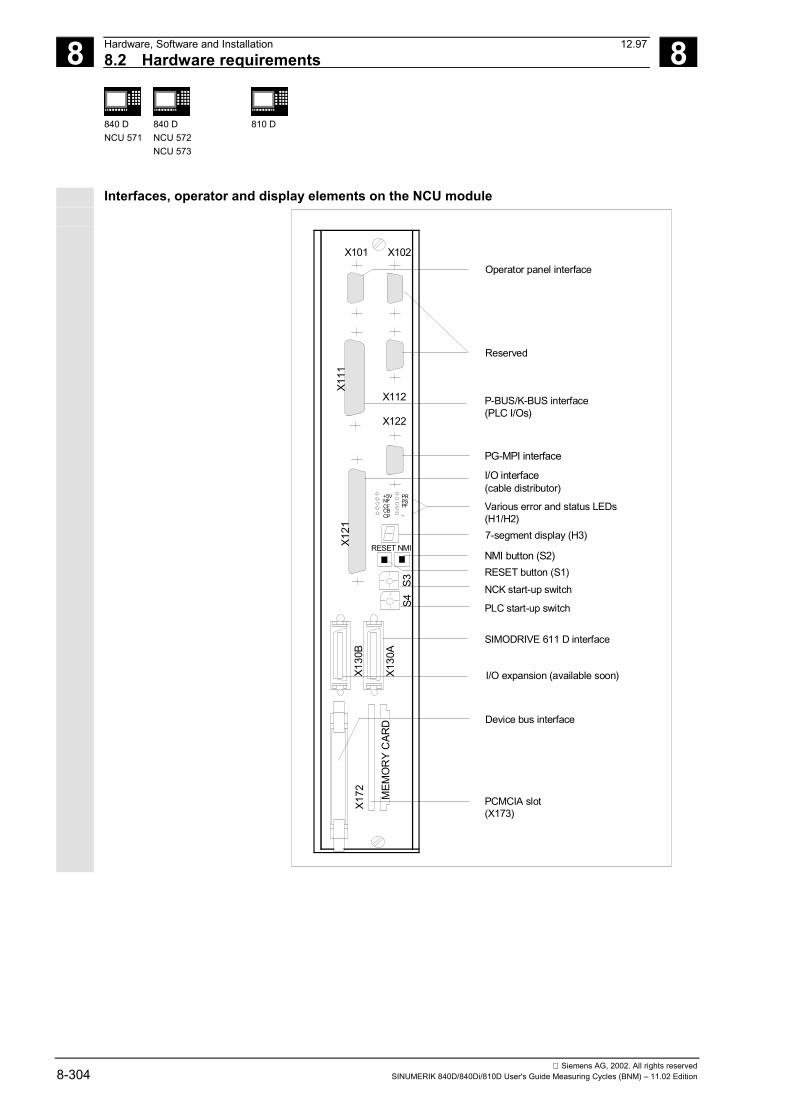
8 Hardware, Software and Installation 12.978.2 Hardware requirements 8
840 DNCU 571
840 DNCU 572NCU 573
810 D
Siemens AG, 2002. All rights reserved8-304 SINUMERIK 840D/840Di/810D User's Guide Measuring Cycles (BNM) – 11.02 Edition
Interfaces, operator and display elements on the NCU module
CF
+5VNF
CBCP
PRPSPF
-
MEM
OR
Y C
ARD
S3
X130
B
X130
A
X121
X111
S4
X172
Operator panel interface
Reserved
P-BUS/K-BUS interface(PLC I/Os)
PG-MPI interface
I/O interface(cable distributor)
Various error and status LEDs(H1/H2)7-segment display (H3)
NMI button (S2)RESET button (S1)NCK start-up switch
PLC start-up switch
SIMODRIVE 611 D interface
I/O expansion (available soon)
Device bus interface
PCMCIA slot(X173)
X101 X102
X112
X122
RESET NMI
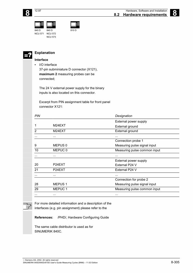
8 12.97 Hardware, Software and Installation8.2 Hardware requirements 8
840 DNCU 571
840 DNCU 572NCU 573
810 D
Siemens AG, 2002. All rights reservedSINUMERIK 840D/840Di/810D User's Guide Measuring Cycles (BNM) – 11.02 Edition 8-305
Explanation
Interface• I/O interface
37-pin subminiature D connector (X121),maximum 2 measuring probes can beconnected;
The 24 V external power supply for the binaryinputs is also located on this connector.
Excerpt from PIN assignment table for front panelconnector X121:
PIN Designation
1 M24EXT
External power supply External ground
2 M24EXT External ground ... ... ...
9 MEPUS 0
Connection probe 1 Measuring pulse signal input
10 MEPUC 0 Measuring pulse common input ... ... ...
20 P24EXT
External power supply External P24 V
21 P24EXT External P24 V ... ... ...
28 MEPUS 1
Connection for probe 2 Measuring pulse signal input
29 MEPUC 1 Measuring pulse common input ... ... ...
For more detailed information and a description of theinterfaces (e.g. pin assignment) please refer to the
References: /PHD/, Hardware Configuring Guide The same cable distributor is used as forSINUMERIK 840C.
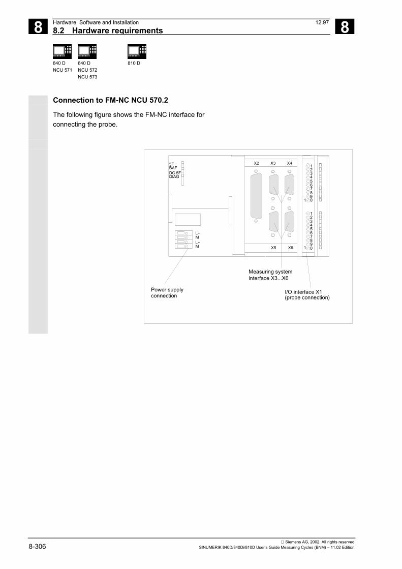
8 Hardware, Software and Installation 12.978.2 Hardware requirements 8
840 DNCU 571
840 DNCU 572NCU 573
810 D
Siemens AG, 2002. All rights reserved8-306 SINUMERIK 840D/840Di/810D User's Guide Measuring Cycles (BNM) – 11.02 Edition
Connection to FM-NC NCU 570.2
The following figure shows the FM-NC interface forconnecting the probe.
X2 X3 X4
X5 X6
5FBAFDC 5FDIAG
L+
L+M
M
Power supplyconnection
I/O interface X1(probe connection)
12345678901
12345678901
Measuring systeminterface X3...X6
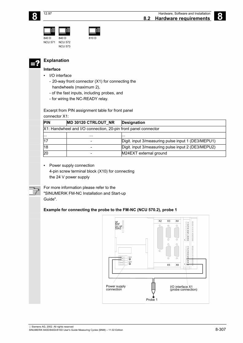
8 12.97 Hardware, Software and Installation8.2 Hardware requirements 8
840 DNCU 571
840 DNCU 572NCU 573
810 D
Siemens AG, 2002. All rights reservedSINUMERIK 840D/840Di/810D User's Guide Measuring Cycles (BNM) – 11.02 Edition 8-307
Explanation
Interface• I/O interface
- 20-way front connector (X1) for connecting the handwheels (maximum 2),
- of the fast inputs, including probes, and- for wiring the NC-READY relay.
Excerpt from PIN assignment table for front panelconnector X1:
PIN MD 30120 CTRLOUT_NR Designation X1: Handwheel and I/O connection, 20-pin front panel connector ... ... ... 17 - Digit. input 3/measuring pulse input 1 (DE3/MEPU1) 18 - Digit. input 3/measuring pulse input 2 (DE3/MEPU2) 20 - M24EXT external ground
• Power supply connection4-pin screw terminal block (X10) for connectingthe 24 V power supply
For more information please refer to the"SINUMERIK FM-NC Installation and Start-upGuide".
Example for connecting the probe to the FM-NC (NCU 570.2), probe 1
X2 X3 X4
X5 X6
5FBAFDC 5FDIAG
L+
L+M
M
Power supplyconnection
Probe 1
I/O interface X1(probe connection)
12345678901
12345678901
8 Hardware, Software and Installation 12.978.3 Software requirements 8
840 DNCU 571
840 DNCU 572NCU 573
810 D
Siemens AG, 2002. All rights reserved8-308 SINUMERIK 840D/840Di/810D User's Guide Measuring Cycles (BNM) – 11.02 Edition
8.3 Software requirements
Explanation
How the measuring cycles are suppliedThe measuring cycles and data blocks you requirefor data definition are supplied on diskette inMS-DOS format.
The measuring cycles are read into the programmemory of the control in the standard cyclesdirectory via the RS-232-C interface.
8.3.1 General measuring cycles
Explanation
NC SW versionFor correct execution of the measuring cycles,NC SW 3.2 or higher is required.
MMC SWThe functions measuring results display screen andparameter assignment via input dialog require MMCSW 3.2 or higher.
PLC programThe measuring cycles execute with the basic PLCprogram, it is not necessary to adapt them to the PLCuser program. The measuring function is activated inthe measuring cycles via the MEAS command.
06.00
8 12.97 Hardware, Software and Installation8.3 Software requirements 8
840 DNCU 571
840 DNCU 572NCU 573
810 D
Siemens AG, 2002. All rights reservedSINUMERIK 840D/840Di/810D User's Guide Measuring Cycles (BNM) – 11.02 Edition 8-309
8.3.2 Measuring in JOG
Explanation
Options"Measurement in JOG" can only be used if the "Inter-modalactions" option (ASUPs and synchronized actions in all modes) isactive.
Measuring cycle versionFor measuring in JOG, measuring cycle SW 5.3 or higher isrequired. To ensure correction functioning of measuring in JOG, aminimum installation of the following definition files, measuring andauxiliary cycles is required:
GUD5.DEFGUD6.DEF in directory DEFINE on diskette1
CYCLE107.SPFCYCLE108.SPFCYCLE109.SPFCYCLE110.SPFCYCLE111.SPFCYCLE114.SPFCYCLE198.SPFCYCLE199.SPFCYCLE961.SPFCYCLE971.SPFCYCLE976.SPFCYCLE977.SPFCYCLE978.SPF is located in directory CYCLES on diskette 1
NC SW versionFor correct operation of measuring in JOG, NC SW 5.3 and higher(810D SW 3.3 and higher) is required.
MMC SWMMC SW 5.3 and higher is required for measuring in JOG.
PLC programMeasuring in JOG runs with the PLC basic program. No adaptationsin the PLC user program are necessary.
11.02
8 Hardware, Software and Installation 12.978.4 Function check 8
840 DNCU 571
840 DNCU 572NCU 573
810 D
Siemens AG, 2002. All rights reserved8-310 SINUMERIK 840D/840Di/810D User's Guide Measuring Cycles (BNM) – 11.02 Edition
8.4 Function check
Function
Measurement commandThe control has the command MEAS for generatinga measuring block.
The measuring input number is set in the commandparameters.
References: /PAZ/, Programming Guide
Measuring resultsThe results of the measurement command arestored in the system data of the NCK and can beaccessed from the program.
These are:$AC_MEA[<No.>] Software switching signal for the probe
No. stands for measuring input number$AA_MW[<Axis>] Measured value of the axis in workpiece coordinates
Axis stands for the name of the measuring axis$AA_MM[<Axis>] Measured value of the axis in machine coordinates
References: /PAZ/, Programming Guide
PLC service displayThe functional check of the probe is conducted viaan NC program.
The measuring signal can be controlled via thediagnostics menu "PLC Status".
Status display for measuring signalProbe 1 deflected DB10 DB X107.0Probe 2 deflected DB10 DB X107.1
8 12.97 Hardware, Software and Installation8.4 Function check 8
840 DNCU 571
840 DNCU 572NCU 573
810 D
Siemens AG, 2002. All rights reservedSINUMERIK 840D/840Di/810D User's Guide Measuring Cycles (BNM) – 11.02 Edition 8-311
Example of functional check
%_N_CHECK_PROBE_MPF;$PATH=/_N_MPF_DIR;Test program for connecting the probeN05 DEF INT MTSIGNAL ;Flag for signal status
N10 DEF INT ME_NR=1 ;Measuring input numberN20 DEF REAL MEAS.VALUE_IN_XN30 G17 T1 D1 ;Preselect tool offset
;for probe
N40 _ANF: G0 G90 X0 F150 ;Start position and measuring velocityN50 MEAS=ME_NR G1 X100 ;Measurement at measuring input 1
;in the X axisN60 STOPREN70 MTSIGNAL=$AC_MEA[1] ;Read software switching signal
;at 1st measuring inputN80 IF MTSIGNAL == 0 GOTOF _ERR1 ;Evaluation of signalN90 MEAS.VALUE_IN_X=$AA_MW[X] ;Read in measured value in
;workpiece coordinateN95 M0N100 M02N110 _ERR1: MSG ("Probe is not operating!")N120 M0N130 M02
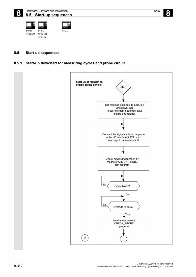
8 Hardware, Software and Installation 12.978.5 Start-up sequences 8
840 DNCU 571
840 DNCU 572NCU 573
810 D
Siemens AG, 2002. All rights reserved8-312 SINUMERIK 840D/840Di/810D User's Guide Measuring Cycles (BNM) – 11.02 Edition
8.5 Start-up sequences
8.5.1 Start-up flowchart for measuring cycles and probe circuit
Start-up of measuringcycles on the control
Start
Check measuring function bymeans of CHECK_PROBE
test program
Single block?No
12
Yes
Yes
Override to zero?No
Load and preselectCHECK_PROBE
program
Set machine data acc. to Sect. 8.1and power ON
(if user memory not empty savebefore and reload)
Connect the signal cable of the probeto the I/O interface X 121 or X 1
(corresp. to type of control)
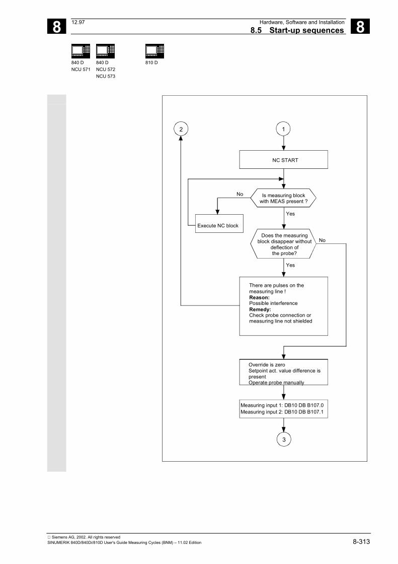
8 12.97 Hardware, Software and Installation8.5 Start-up sequences 8
840 DNCU 571
840 DNCU 572NCU 573
810 D
Siemens AG, 2002. All rights reservedSINUMERIK 840D/840Di/810D User's Guide Measuring Cycles (BNM) – 11.02 Edition 8-313
No
12
NC START
Is measuring blockwith MEAS present ?
Execute NC block
Yes
Yes
No
3
Measuring input 1: DB10 DB B107.0Measuring input 2: DB10 DB B107.1
Does the measuringblock disappear without
deflection ofthe probe?
There are pulses on themeasuring line !Reason:Possible interferenceRemedy:Check probe connection ormeasuring line not shielded
Override is zeroSetpoint act. value difference ispresentOperate probe manually
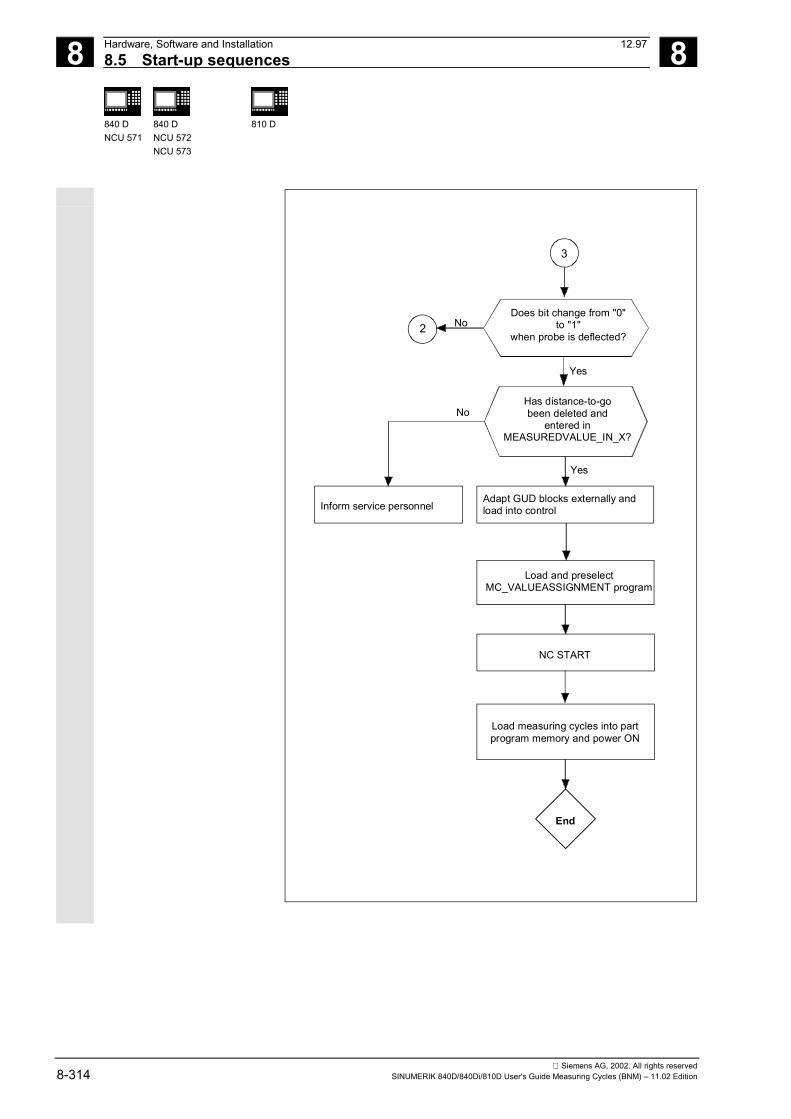
8 Hardware, Software and Installation 12.978.5 Start-up sequences 8
840 DNCU 571
840 DNCU 572NCU 573
810 D
Siemens AG, 2002. All rights reserved8-314 SINUMERIK 840D/840Di/810D User's Guide Measuring Cycles (BNM) – 11.02 Edition
3
Yes
No
End
NC START
No
Yes
Inform service personnel
2Does bit change from "0"
to "1"when probe is deflected?
Has distance-to-gobeen deleted and
entered in MEASUREDVALUE_IN_X?
Adapt GUD blocks externally andload into control
Load and preselectMC_VALUEASSIGNMENT program
Load measuring cycles into partprogram memory and power ON
8 12.97 Hardware, Software and Installation8.5 Start-up sequences 8
840 DNCU 571
840 DNCU 572NCU 573
810 D
Siemens AG, 2002. All rights reservedSINUMERIK 840D/840Di/810D User's Guide Measuring Cycles (BNM) – 11.02 Edition 8-315
8.5.2 Starting up the measuring cycle interface for the MMC 102
Function
In SW 3.2 and higher, the measuring cycles offer theoption of displaying the measurement result screensand setting the input parameters via a dialog (callCYCLE103). These functions require adaptations inthe MMC software on the control.
Explanation
MMC 102In the "Start-up" operating area you can access theMMC file system via the softkeys "MMC" and"DOS-Shell".
In the filec:\mmc2\comic.nskthe comment has to be removed in the second line.
REM TOPIC(... � TOPIC(...
Then the MMC has to be started again.
Testing the measuring cycle interfaceThe cycle CYCLE103 can be activated and run inautomatic mode.
When functioning properly, a screen is displayedwith an overview of the measuring cycles; the dialogbox for setting the measuring parameter cycles canbe opened from here.
�
8 Hardware, Software and Installation 12.978.5 Start-up sequences 8
840 DNCU 571
840 DNCU 572NCU 573
810 D
Siemens AG, 2002. All rights reserved8-316 SINUMERIK 840D/840Di/810D User's Guide Measuring Cycles (BNM) – 11.02 Edition
Notes
9 12.97 Supplementary Conditions 9
840 DNCU 571
840 DNCU 572NCU 573
810 D 840 Di
Siemens AG, 2002. All rights reservedSINUMERIK 840D/840Di/810D User's Guide Measuring Cycles (BNM) – 11.02 Edition 9-317
Supplementary Conditions
There are no special conditions for the measuringcycles. However, the following memory capacityrequirements should be taken into account.
Memory requirementThe measuring cycles require the following memorycapacity in the NC program memory of the control:
Memory requirements[in KB]
Full number of measuring cycles approx. 190Measuring cycles for milling machines approx. 150Measuring cycles for turning machines approx. 120
�
06.00

9 Supplementary Conditions 12.97 9
840 DNCU 571
840 DNCU 572NCU 573
810 D 840 Di
Siemens AG, 2002. All rights reserved9-318 SINUMERIK 840D/840Di/810D User's Guide Measuring Cycles (BNM) – 11.02 Edition
Notes
10 12.97 Data Description 10
Siemens AG, 2002. All rights reservedSINUMERIK 840D/840Di/810D User's Guide Measuring Cycles (BNM) – 11.02 Edition 10-319
Data Description
10.1 Machine data for machine cycle runs.......................................................................... 10-320
10.2 Cycle data ................................................................................................................... 10-32310.2.1 Data concept for measuring cycles ....................................................................... 10-32310.2.2 Data blocks for measuring cycles: GUD5.DEF and GUD6.DEF........................... 10-32410.2.3 Central values ....................................................................................................... 10-32810.2.4 Central bits ............................................................................................................ 10-33310.2.5 Central strings ....................................................................................................... 10-33610.2.6 Channel-oriented values ....................................................................................... 10-33710.2.7 Channel-oriented bits ............................................................................................ 10-339
10.3 Data for measuring in JOG ........................................................................................ 10-34410.3.1 Machine data for ensuring ability to function......................................................... 10-34410.3.2 Modifying the GUD7 data block ............................................................................ 10-34610.3.3 Settings in data block GUD6................................................................................. 10-34910.3.4 Loading files for measuring in JOG....................................................................... 10-351
06.00
10 Data Description 12.9710.1 Machine data for machine cycle runs 10
840 DNCU 571
840 DNCU 572NCU 573
810 D 840 Di
Siemens AG, 2002. All rights reserved10-320 SINUMERIK 840D/840Di/810D User's Guide Measuring Cycles (BNM) – 11.02 Edition
10.1 Machine data for machine cycle runs
Function
Memory-configuring machine dataAs the measuring cycles have to run with GUD andLUD variables (Global User Data and Local UserData), the following minimum settings must be madein the data for the memory configuration:
18118 MM_NUM_GUD_MODULESMD number Number of data blocks
Default setting: 7When using measuring cycles: 7
min. input value: 1 max. input value: 9
Changes are validated by Power ON Protection level: 2/7 Unit: -
Data type: DWORD valid as of software version: SW 2
Meaning: Number of GUD files in the active file system (SRAM)
18120 MM_NUM_GUD_NAMES_NCKMD number Number of GUD variables in PLC
Default setting: 10When using measuring cycles: 20
min. input value: 0 max. input value: 400
Changes are validated by Power ON Protection level: 2/7 Unit: -
Data type: DWORD valid as of software version: SW 1
Meaning: Number of global user variables (SRAM)
18130 MM_NUM_GUD_NAMES_CHANMD number Number of GUD variables per channel
Default setting: 10When using measuring cycles: 100
min. input value: 0 max. input value: 200
Changes are validated by Power ON Protection level: 2/7 Unit: -
Data type: DWORD valid as of software version: SW 1
Meaning: Number of channel-specific user variables (SRAM)
18150 MM_GUD_VALUES_MEMMD number Memory for values of the GUD variables
Default setting: 12When using measuring cycles: 60
min. input value: 0 max. input value: 50
Changes are validated by Power ON Protection level: 2/7 Unit: KB
Data type: DWORD valid as of software version: SW 1
Meaning: Memory for user variables (SRAM)
10 12.97 Data Description10.1 Machine data for machine cycle runs 10
840 DNCU 571
840 DNCU 572NCU 573
810 D 840 Di
Siemens AG, 2002. All rights reservedSINUMERIK 840D/840Di/810D User's Guide Measuring Cycles (BNM) – 11.02 Edition 10-321
18170 MM_NUM_MAX_FUNC_NAMESMD number Number of special functions (cycles, DRAM)
Default setting: 40When using measuring cycles: 70
min. input value: 0.0 max. input value: plus
Changes are validated by Power ON Protection level: 2/7 Unit: -
Data type: DWORD valid as of software version: SW 1
Meaning: Number of cycles with input parameters
18180 MM_NUM_MAX_FUNC_PARAMMD number Number of special functions (cycles, DRAM)
Default setting: 300When using measuring cycles: 600
min. input value: 0.0 max. input value: plus
Changes are validated by Power ON Protection level: 2/7 Unit: -
Data type: DWORD valid as of software version: SW 1
Meaning: Number of additional parameters for cycles acc. to MD 18170
28020 MM_NUM_LUD_NAMES_TOTALMD number Number of LUD variables in total (in all program levels)
Default setting: 200When using measuring cycles: 200
min. input value: 0 max. input value: 300
Changes are validated by Power ON Protection level: 2/7 Unit: -
Data type: DWORD valid as of software version: SW 3.2
Meaning: Number of local user variables (DRAM)
These machine data are for configuring the supportedmemory area of the PLC.
Therefore, make sure that they are set beforeinitiating start-up.
Otherwise, all data from the user program (NC pro-gram memory including cycles, tool offsets and Rparameters) have to be backed up and read back inagain.
11.02
10 Data Description 12.9710.1 Machine data for machine cycle runs 10
840 DNCU 571
840 DNCU 572NCU 573
810 D 840 Di
Siemens AG, 2002. All rights reserved10-322 SINUMERIK 840D/840Di/810D User's Guide Measuring Cycles (BNM) – 11.02 Edition
Function
Machine data for adapting the probe
13200 MEAS_PROBE_LOW_ACTIVEMD number Switching performance of the probe
Default setting: 0When using measuring cycles: 0
min. input value: FALSE max. input value: TRUE
Changes are validated by Power ON Protection level: 2/7 Unit: -
Data type: BOOLEAN valid as of software version: SW 2.2
Meaning: Value 0: (Default setting) Non-deflected state 0 V
Deflected state 24 VValue 1: Non-deflected state 24 V
Deflected state 0 V
Machine data for adapting MMC commands in cycles
10132 MMC_CMD_TIMEOUTMD number Monitoring time for MMC command in part program
Default setting: 1When using measuring cycles: 3
min. input value: 1 max. input value: 100
Changes are validated by Power ON Protection level: 2/7 Unit: s
Data type: DOUBLE valid as of software version: SW 3.2
Meaning: Monitors the time until the MMC acknowledges a command from the part program.
Machine data for logging
11420 LEN_PROTOCOL_FILEMD number File size for log files (KB)
Default setting: 1When using measuring cycles: 5
min. input value: 1 max. input value: 1000
Changes are validated by Power ON Protection level: 0/0 Unit: -
Data type: DWORD valid as of software version: SW 4.3
Meaning: Size for log file
Machine data for configuring channel-specific system frames
28082 MM_SYSTEM_FRAME_MASKMD number Configuration screen form for channel-specific system frames
Default setting: 21hexWhen using measuring cycles: Bit 0=1;
at least Bit 5=1
min. input value: 0 max. input value: 7Fhex
Changes are validated by Power ON Protection level: 2/7 Unit: -
Data type: INT valid for measuring cycles SW 6.2. and higher
Meaning: Bit 0: 1 System frames for setting actual values and scratchingBit 5: 1 System frames for cycles
11.02
10 12.97 Data Description10.2 Cycle data 10
840 DNCU 571
840 DNCU 572NCU 573
810 D 840 Di
Siemens AG, 2002. All rights reservedSINUMERIK 840D/840Di/810D User's Guide Measuring Cycles (BNM) – 11.02 Edition 10-323
10.2 Cycle data
10.2.1 Data concept for measuring cycles
Function
Measuring cycles are general subroutines designedto solve specific measurement tasks. They can besuitably adapted to the problem at hand by means ofparameter settings. They can be adapted for thispurpose by means of so-called definingparameters.
They also return data such as measurement results.They are stored in result parameters.
Furthermore, the measuring cycles also requireinternal parameters for calculations.
Defining parameters
The defining parameters of the measuring cycles aredefined as GUD variables.
They are stored in the nonvolatile memory area ofthe control, their setting values remain stored evenwhen the control is switched off and on.
These data are contained in the data definitionblocks• GUD5.DEF and• GUD6.DEF which are supplied together with the measuringcycles. These blocks must be loaded into the control duringstart-up. They must then be adapted according tothe characteristics of the relevant machine by themachine manufacturer.
10 Data Description 12.9710.2 Cycle data 10
840 DNCU 571
840 DNCU 572NCU 573
810 D 840 Di
Siemens AG, 2002. All rights reserved10-324 SINUMERIK 840D/840Di/810D User's Guide Measuring Cycles (BNM) – 11.02 Edition
The value for the defining parameters of the measuringcycles in module GUD5.DEF can be assigned in theprogram before the cycle is called; this is achieved byoperator input or by starting CYCLE103, which controlsan interactive dialog. The data in the operating area "Parameters", "Userdata" can be selected via "Global user data" or"Channel-specific user data".
Result parameters
The results are also stored as GUD variables in theGUD5 module.
Internal parameters
LUD variables are used in the measuring cycles asinternal arithmetic parameters. These are set up inthe cycle and thus exist only for the duration of therun-time.
10.2.2 Data blocks for measuring cycles: GUD5.DEF and GUD6.DEF
Function
The measuring cycle data are stored in two separatedefinition blocks:• GUD5.DEF Data module for measuring cycle operators• GUD6.DEF Data module for machine manufacturers
The sizes of the fields for the empirical and meanvalues must also be configured by the machinemanufacturer at measuring cycle start-up.
The sizes of the fields for the empirical and meanvalues must also be configured by the machinemanufacturer at measuring cycle start-up. The presetvalues, however, are defined by the measuring cycleoperator.
10 12.97 Data Description10.2 Cycle data 10
840 DNCU 571
840 DNCU 572NCU 573
810 D 840 Di
Siemens AG, 2002. All rights reservedSINUMERIK 840D/840Di/810D User's Guide Measuring Cycles (BNM) – 11.02 Edition 10-325
Excerpt from GUD5.DEF
For adapting the GUD5.DEF module, only thefollowing section is relevant: (An example is provided in Chapter 11). %_N_GUD5_DEF ;$PATH=/_N_DEF_DIR ;<Version> , <Date> ... N40 DEF CHAN REAL _EV[20] N50 DEF CHAN REAL _MV[20] ... N99 M02
Module GUD6.DEF
The general measuring cycle data are configured inthe GUD6.DEF data module. This module is supplied with the measuring cycles inits standard configuration and must be adapted tothe specific requirements of the machine by themachine manufacturer. (An example is provided in Chapter 11).
Contents of GUD6.DEF
This block is supplied with the measuring cycles, withthe following contents for example (see also example inChapter 11): %_N_GUD6_DEF ;$PATH=/_N_DEF_DIR ;V05.04.06 , 14.12.2001 ...
N10 DEF NCK INT _CVAL[4]=(3,3,3,0) N11 DEF NCK REAL _TP[3,10]=(0,0,0,0,0,0,0,133,0,2) N12 DEF NCK REAL _WP[3,11] N13 DEF NCK REAL _KB[3,7] N14 DEF NCK REAL _CM[8]=(60,2000,1,0.005,20,4,10,0) N15 DEF NCK REAL _MFS[6] N20 DEF NCK BOOL _CBIT[16]=(0,0,0,1,0,0,0,0,1,0,0,0,0,0,0,0) N30 DEF NCK STRING[8] _SI[3]=("”,”5”,"”) N40 DEF CHAN INT _EVMVNUM[2]=(20,20) N41 DEF CHAN REAL _SPEED[4]=(50,1000,1000,900)
11.02
10 Data Description 12.9710.2 Cycle data 10
840 DNCU 571
840 DNCU 572NCU 573
810 D 840 Di
Siemens AG, 2002. All rights reserved10-326 SINUMERIK 840D/840Di/810D User's Guide Measuring Cycles (BNM) – 11.02 Edition
N50 DEF CHAN BOOL _CHBIT[20]=(0,1,1,0,0,0,0,0,0,0,0,0,0,0,0,0,0,0,0,0) N60 DEF NCK STRING[32] _PROTNAME[2] N61 DEF NCK STRING[80] _HEADLINE[10] N62 DEF NCK INT _PROTFORM[6]=SET(60,80,1,5,1,12) N63 DEF NCK CHAR _PROTSYM[2] N64 DEF NCK STRING[100] _PROTVAL[13] N65 DEF NCK INT _PMI[4] N66 DEF NCK INT _SP_B[20] N67 DEF NCK STRING[12] _TXT[100] N68 DEF NCK INT _DIGIT=3 ... N92 DEF CHAN INT _JM_I[5]=SET(0,1,1,17,0) N93 DEF CHAN BOOL _JM_B[7]=SET(0,1,0,0,0,0,0) M17
In the delivery status, the following settings are active:• Number of data fields (N01), 3 data fields each for
- tool probe (N11),- workpiece probe (N12)- calibrating piece (N13);
• Monitoring data for tool measurement with rotatingspindle and cyclic calculation (N14):- max. grinding wheel surface speed 60 m/min,- max. speed 2000 rpm,- Fmin=1 mm/min,- measuring accuracy 0.005 mm,- Fmax for probing 20 mm/min,- direction of rotation M4,- double probing with feedrate factor 10 for first probing;
• Central bits (N20)- no measurement repetition or exceeding of dimensional difference and safe area,- no M0 for measurement repetition- no M0 for "Oversize", "Undersize", "Dimensional difference",- metric basic system,- tool measurement and calibration with CYCLE982 performed in the basic coordinate system (machine coordinate system with kinematic transformation switched off)- correction of monoprobe position with _CORA,- use of the standard log header,- cycle-internal calculation of speed and feedrate in tool measurement with rotating spindle,- length of the workpiece probe with reference to probe tip;
11.02
10 12.97 Data Description10.2 Cycle data 10
840 DNCU 571
840 DNCU 572NCU 573
810 D 840 Di
Siemens AG, 2002. All rights reservedSINUMERIK 840D/840Di/810D User's Guide Measuring Cycles (BNM) – 11.02 Edition 10-327
• Software status of the control – SW 5• Channel-oriented values (N40)
- 20 memories for empirical and mean values;• Channel-oriented values (N41)
- 50% rapid traverse velocity,- positioning feed in the plane 1000 mm/min- positioning feed in the infeed axis 900 mm/min;
• Channel-oriented bits (N50)- measurement input 1 for connecting a workpiece probe,- measurement input 2 for connecting a tool probe,- collision detection active in motion blocks generated by measurement cycles- entry of the tool data for tool measurement in the geo memory,- no mean value storage,- empirical value is subtracted from measured actual value,- in workpiece measurement with automatic TO additive offset is implemented in the wear memory- no measurement result screen display,- no coupling of spindle position with coordinate rotation in the plane,- max. 5 measurement attempts,- retraction from the measuring point at the same velocity as for intermediate positioning,- measuring feed on defined by _VMS;
• Central values for logging (N62)- 60 lines per page,- 80 characters per line,- start page number is 1,- number of header lines is 5,- number of value lines in log is 1,- number of characters per column is 12,
• Central values for logging (N68)- number of decimal places is 3
• Channel-oriented values for measurement in JOG (N92)- no entry of data field number for probe like in ShopMill- number of the data field for the workpiece probe is 1- number of the data field for the tool probe is 1- working plane for measurement in JOG is G17- active ZO number for measurement in JOG is 0 (G500)
• Channel-oriented bits for measurement in JOG (N93)- offset in geometry for tool measurement- 1 measurement attempt- retraction from the measuring point at the same velocity as for intermediate positioning- no fast measuring feed
11.02
10 Data Description 12.9710.2 Cycle data 10
840 DNCU 571
840 DNCU 572NCU 573
810 D 840 Di
Siemens AG, 2002. All rights reserved10-328 SINUMERIK 840D/840Di/810D User's Guide Measuring Cycles (BNM) – 11.02 Edition
10.2.3 Central values _CVAL Number of elements
min. input value: - max. input value: -
Changes valid after value assignment Protection level: - Unit: -
Data type: INTEGER valid as of software version: SW 3.2
Meaning: Default setting_CVAL[0] Number of tool probes 3_CVAL[1] Number of workpiece probes 3_CVAL[2] Number of calibration probes 3_CVAL[3] Not currently assigned 0
_TP Tool probe
min. input value: - max. input value: -
Changes valid after value assignment Protection level: 2/7 Unit: -
Data type: REAL valid as of software version: SW 3.2
Meaning: Default settingIndex "x" stands for the number of the current probe - 1
Assignment for milling _TP[x,0] Trigger point in minus direction X (1st geometry axis) 0_TP[x,1] Trigger point in plus direction X (1st geometry axis) 0_TP[x,2] Trigger point in minus direction Y (2nd geometry axis) 0_TP[x,3] Trigger point in plus direction Y (2nd geometry axis) 0_TP[x,4] Trigger point in minus direction Z (3rd geometry axis) 0_TP[x,5] Trigger point in plus direction Z (3rd geometry axis) 0_TP[x,6] Edge length/disk diameter 0_TP[x,7] Internal assignment 133
_TP[x,8) Probe type 0: Cube 0 101: Wheel in XY 201: Wheel in ZX 301: Wheel in YZ _TP[x,9] Distance between upper edge of tool probe and lower edge of tool 2 Assignment for turning _TP[x,0] Trigger point in minus direction of abscissa 0_TP[x,1] Trigger point in plus direction of abscissa 0_TP[x,2] Trigger point in minus direction of ordinate 0_TP[x,3] Trigger point in plus direction of ordinate 0_TP[x,4] Without meaning 0to
_TP[x,9] Without meaning 0
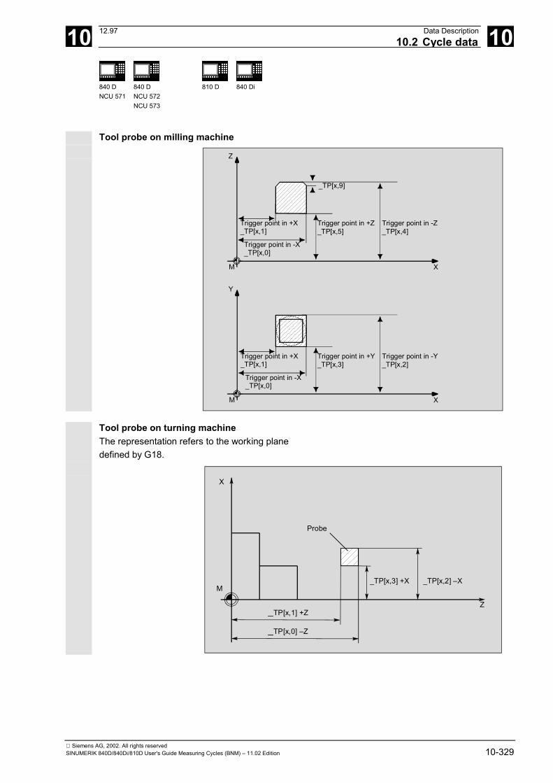
10 12.97 Data Description10.2 Cycle data 10
840 DNCU 571
840 DNCU 572NCU 573
810 D 840 Di
Siemens AG, 2002. All rights reservedSINUMERIK 840D/840Di/810D User's Guide Measuring Cycles (BNM) – 11.02 Edition 10-329
Tool probe on milling machine
Z
Trigger point in +Z_TP[x,5]
Trigger point in -Z_TP[x,4]
M
Trigger point in +X_TP[x,1]
X
Trigger point in -X_TP[x,0]
_TP[x,9]
Y
Trigger point in +Y_TP[x,3]
Trigger point in -Y_TP[x,2]
M
Trigger point in +X_TP[x,1]
X
Trigger point in -X_TP[x,0]
Tool probe on turning machine
The representation refers to the working planedefined by G18.
X
Z
M_TP[x,3] +X _TP[x,2] –X
Probe
_TP[x,1] +Z
_TP[x,0] –Z
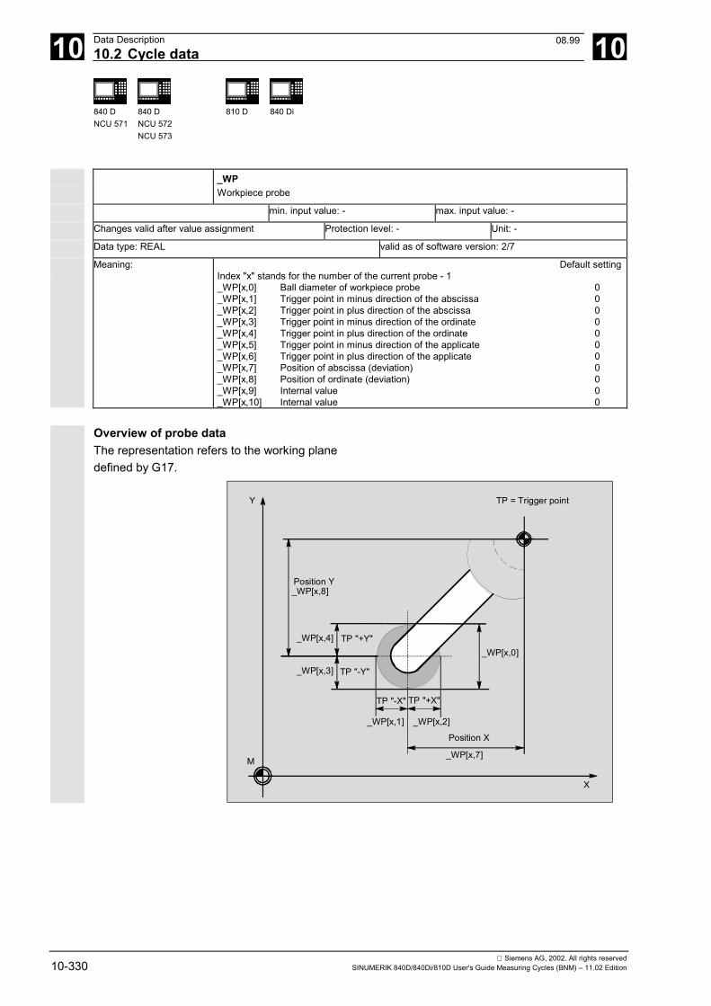
10 Data Description 12.9710.2 Cycle data 10
840 DNCU 571
840 DNCU 572NCU 573
810 D 840 Di
Siemens AG, 2002. All rights reserved10-330 SINUMERIK 840D/840Di/810D User's Guide Measuring Cycles (BNM) – 11.02 Edition
_WP Workpiece probe
min. input value: - max. input value: -
Changes valid after value assignment Protection level: - Unit: -
Data type: REAL valid as of software version: 2/7
Meaning: Default settingIndex "x" stands for the number of the current probe - 1_WP[x,0] Ball diameter of workpiece probe 0_WP[x,1] Trigger point in minus direction of the abscissa 0_WP[x,2] Trigger point in plus direction of the abscissa 0_WP[x,3] Trigger point in minus direction of the ordinate 0_WP[x,4] Trigger point in plus direction of the ordinate 0_WP[x,5] Trigger point in minus direction of the applicate 0_WP[x,6] Trigger point in plus direction of the applicate 0_WP[x,7] Position of abscissa (deviation) 0_WP[x,8] Position of ordinate (deviation) 0
_WP[x,9] Internal value 0_WP[x,10] Internal value 0
Overview of probe data
The representation refers to the working planedefined by G17.
Y
M
X
TP = Trigger point
Position Y_WP[x,8]
_WP[x,4]
_WP[x,3]
_WP[x,1] _WP[x,2]
_WP[x,7]
Position X
_WP[x,0]TP "+Y"
TP "-Y"
TP "-X" TP "+X"
08.99
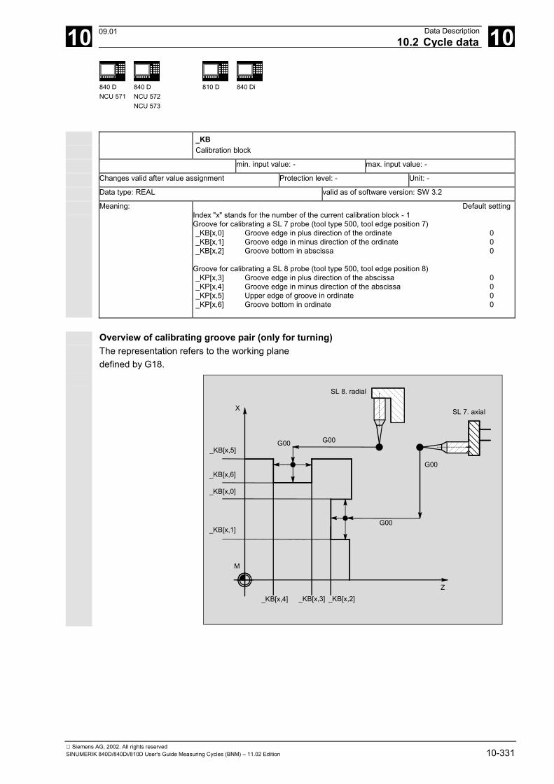
10 12.97 Data Description10.2 Cycle data 10
840 DNCU 571
840 DNCU 572NCU 573
810 D 840 Di
Siemens AG, 2002. All rights reservedSINUMERIK 840D/840Di/810D User's Guide Measuring Cycles (BNM) – 11.02 Edition 10-331
_KB Calibration block
min. input value: - max. input value: -
Changes valid after value assignment Protection level: - Unit: -
Data type: REAL valid as of software version: SW 3.2
Meaning: Default settingIndex "x" stands for the number of the current calibration block - 1Groove for calibrating a SL 7 probe (tool type 500, tool edge position 7)_KB[x,0] Groove edge in plus direction of the ordinate 0_KB[x,1] Groove edge in minus direction of the ordinate 0_KB[x,2] Groove bottom in abscissa 0
Groove for calibrating a SL 8 probe (tool type 500, tool edge position 8)_KP[x,3] Groove edge in plus direction of the abscissa 0_KP[x,4] Groove edge in minus direction of the abscissa 0_KP[x,5] Upper edge of groove in ordinate 0_KP[x,6] Groove bottom in ordinate 0
Overview of calibrating groove pair (only for turning)
The representation refers to the working planedefined by G18.
X
M
G00 G00
G00
G00
SL 8. radial
SL 7. axial
_KB[x,5]
_KB[x,6]
_KB[x,0]
_KB[x,1]
_KB[x,4] _KB[x,3] _KB[x,2]Z
09.01
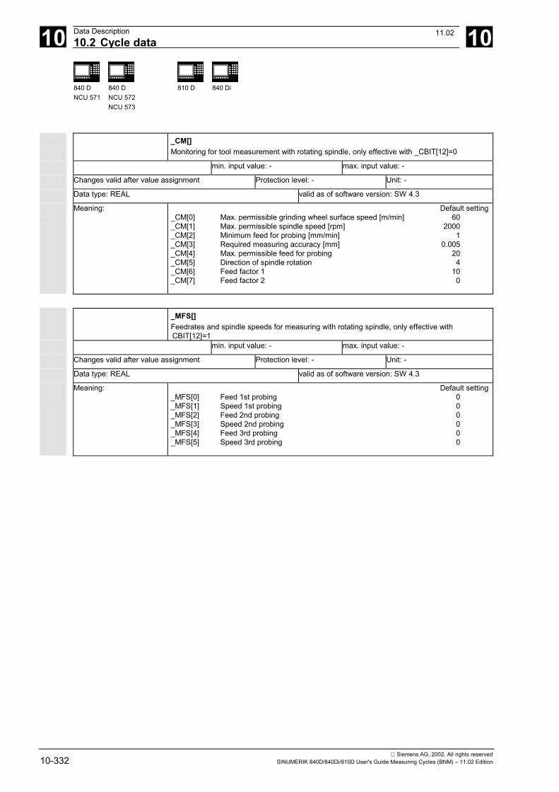
10 Data Description 12.9710.2 Cycle data 10
840 DNCU 571
840 DNCU 572NCU 573
810 D 840 Di
Siemens AG, 2002. All rights reserved10-332 SINUMERIK 840D/840Di/810D User's Guide Measuring Cycles (BNM) – 11.02 Edition
_CM[] Monitoring for tool measurement with rotating spindle, only effective with _CBIT[12]=0
min. input value: - max. input value: -
Changes valid after value assignment Protection level: - Unit: -
Data type: REAL valid as of software version: SW 4.3
Meaning: Default setting_CM[0] Max. permissible grinding wheel surface speed [m/min] 60_CM[1] Max. permissible spindle speed [rpm] 2000_CM[2] Minimum feed for probing [mm/min] 1_CM[3] Required measuring accuracy [mm] 0.005_CM[4] Max. permissible feed for probing 20_CM[5] Direction of spindle rotation 4_CM[6] Feed factor 1 10_CM[7] Feed factor 2 0
_MFS[] Feedrates and spindle speeds for measuring with rotating spindle, only effective with
CBIT[12]=1
min. input value: - max. input value: -
Changes valid after value assignment Protection level: - Unit: -
Data type: REAL valid as of software version: SW 4.3 Meaning: Default setting
_MFS[0] Feed 1st probing 0_MFS[1] Speed 1st probing 0_MFS[2] Feed 2nd probing 0_MFS[3] Speed 2nd probing 0_MFS[4] Feed 3rd probing 0_MFS[5] Speed 3rd probing 0
11.02
10 12.97 Data Description10.2 Cycle data 10
840 DNCU 571
840 DNCU 572NCU 573
810 D 840 Di
Siemens AG, 2002. All rights reservedSINUMERIK 840D/840Di/810D User's Guide Measuring Cycles (BNM) – 11.02 Edition 10-333
10.2.4 Central bits _CBIT Central bits
min. input value: 0 max. input value: 1
Changes valid after value assignment Protection level: - Unit: -
Data type: BOOLEAN valid as of software version: SW 3.2
Meaning: Default setting_CBIT[0] Measurement repetition after exceeding
dimensional difference and safe area 0_CBIT[1] M0 on measurement repetition 0_CBIT[2] No M0 on alarm
"Oversize", "undersize","Permissible dimensional difference exceeded" 0
_CBIT[3] Flag for basic system setting of the control 1_CBIT[4] Currently not assigned 0
_CBIT[6...7] Currently not assigned 0 _CBIT[8] Offset for mono probe position 0_CBIT[9] Internally assigned 0
_CBIT[10] Log destination 0 _CBIT[11] Log header 0 _CBIT[12] (only relevant for measuring milling tools with rotating spindle)
0: Calculation of feedrate and spindle speed through measuring cycle 01: Specified by user
_CBIT[13] 1: Delete the measuring cycle fields in GUD6 _TP[],_WP[], _KB[], _EV[],_MV[] 0
Measuring cycles SW 4.5and higher
_CBIT[14] 0: Length of the probe relative to the center of the probe ball 01: Length of the probe relative to the end
(only for probe type 710 or 2xx) _CBIT[15] 0: No effect 0
1: Enter result of probe ball computation in the geometry memory of the probe (radius)
Measuring cycles SW 5.4
and higher _CBIT[5] 0: Tool measurement and calibration of the tool probe 0
is performed in the basic coordinate system (in the machine coordinate system with the kinematic transformation switched off (only for CYCLE982)
1: Tool measurement and calibration of the tool probe is performed in the active WCS (only for CYCLE982)
Measurement repeated
If _CBIT[0] is set and the calculated difference exceedsthe values of the parameters for dimensional differenceand safe area, the measurement is repeated. An alarm is only displayed in the alarm line withmeasurement repetition if _CBIT[1] is set.
11.02
10 Data Description 12.9710.2 Cycle data 10
840 DNCU 571
840 DNCU 572NCU 573
810 D 840 Di
Siemens AG, 2002. All rights reserved10-334 SINUMERIK 840D/840Di/810D User's Guide Measuring Cycles (BNM) – 11.02 Edition
M0 with measurement repetition If _CBIT[1] is set, and the parameter limits fordimensional difference control and safe area wereexceeded, the repetition of the measurement must bestarted with NC START. An alarm is displayed in the alarm line; it requires noacknowledgment.
No M0 on alarm If _CBIT[2] is not set, M0 is not generated if the alarms"Oversize", "Undersize" or "Permissible dimensionaldifference exceeded" are output.
Flag for basic system setting When starting up the measuring cycles, this bit has tobe set according to the basic settings of the PLC(MD 10240).• 0: INCH• 1: Metric If modifying the basic settings of the PLC results in_CBIT[3] no longer matching MD 10240, measuringcycles software versions up to and including SW 4.4 willdelete data fields _TP[], _WP[], _KB[] and _EV[] the firsttime a measuring cycle is called after the modificationhas been made, will output a message indicating this,and will terminate the measuring cycle. The user must calibrate the tool probe or workpieceprobe before measuring tasks can be solved again. For measuring cycles SW 4.5 and higher, these datafields are not deleted but converted. This means that itis no longer necessary to recalibrate the tool probe orworkpiece probe. The data for tool measurement withrotating spindle (_CM[], _MFS[]) are also converted.
Tool measurement and calibration in the WCS (for use with CYCLE982 only) Measuring cycles versions SW 5.4 and higher permittool measurement and calibration of the probe in theactive WCS if _CBIT[5] is set. This requires the sameWCS preconditions for calibration and measurement.That also permits tool measurement with activeTRAANG transformation.
11.02
10 12.97 Data Description10.2 Cycle data 10
840 DNCU 571
840 DNCU 572NCU 573
810 D 840 Di
Siemens AG, 2002. All rights reservedSINUMERIK 840D/840Di/810D User's Guide Measuring Cycles (BNM) – 11.02 Edition 10-335
Mono probe position offset
If _CBIT[8] is set, the probe position is offset by thevalue programmed in _CORA.
Log destination
The destination for the log procedure can be selectedvia bit _CBIT[10]. With _CBIT[10]=0 the log is sent to adevice, for example a printer, via RS-232-C; with_CBIT[10]=1 the log is sent to a file (not yetimplemented).
Log header
_CBIT[11] is for selecting the log header. The standard logheader is selected with _CBIT[11]=0. With _CBIT[11]=1you can use a customized log header.
Calculating feedrate and speed usingmeasuring cycle
If _CBIT[12]=0 is set, feedrate and spindle speed iscalculated for tool measurement of milling tools withrotating spindle via the measuring cycle. If _CBIT[12]=1,the user specifies the feedrate and the spindle speed indata field _MFS[6].
Deleting measuring cycle data fields in the GUD6 block
If _CBIT[13]=1, the data fields _TP[],_WP[], _KB[], EV[], _MV[] and_CBIT[13] are zeroed for the following measuring cycle call.
Length of the probe (only for tool type 710 or 2xx)
If _CBIT[14]=0, the length of the probe must be enteredrelative to the center of the probe ball.If _CBIT[14]=1, the length of the probe must be enteredrelative to the end of the probe ball.
Enter the effect probe ball radius in thegeometry memory (only for tool type 710 or 2xx)
If _CBIT[15]=1, the probe ball computation is calibrated byentering the active probe ball radius in the geometrymemory of the probe.
08.99
10 Data Description 12.9710.2 Cycle data 10
840 DNCU 571
840 DNCU 572NCU 573
810 D 840 Di
Siemens AG, 2002. All rights reserved10-336 SINUMERIK 840D/840Di/810D User's Guide Measuring Cycles (BNM) – 11.02 Edition
10.2.5 Central strings _SI Central strings
min. input value: - max. input value: -
Changes valid after value assignment Protection level: - Unit: -
Data type: STRING valid as of software version:
Meaning: Default setting_SI[0] Currently not assigned_SI[1] Software version 4
Software version
Here you have to enter the first digit of the version ofthe NCU software on the control, e.g. for SW 03.06.02,enter 3.
10 12.97 Data Description10.2 Cycle data 10
840 DNCU 571
840 DNCU 572NCU 573
810 D 840 Di
Siemens AG, 2002. All rights reservedSINUMERIK 840D/840Di/810D User's Guide Measuring Cycles (BNM) – 11.02 Edition 10-337
10.2.6 Channel-oriented values _EVMVNUM Number of empirical values and mean values
min. input value: 0 max. input value: -
Changes valid after value assignment Protection level: - Unit: -
Data type: INTEGER valid as of software version: SW 3.2
Meaning: Default setting_EVMVNUM[0] Number of empirical values 20_EVMVNUM[1] Number of mean values 20
_EV Empirical values
min. input value: - max. input value: -
Changes valid after value assignment Protection level: - Unit: -
Data type: REAL valid as of software version: SW 3.2
Meaning: Default settingIndex "x" stands for the number of the empirical value - 1
_EV[x] Number of empirical values 0 _MV Mean values
min. input value: - max. input value: -
Changes valid after value assignment Protection level: - Unit: -
Data type: REAL valid as of software version: SW 3.2
Meaning: Default settingIndex "x" stands for the number of the mean value - 1
_MV[x] Mean value 0 _SPEED Traversing velocities for intermediate positioning
min. input value: 0 max. input value: 100
Changes valid after value assignment Protection level: - Unit: -
Data type: REAL valid as of software version: SW 3.2
Meaning: Default setting_SPEED[0] Rapid traverse speed in % when
collision monitoring is not active(values between 1 and 100) 50
_SPEED[1] Positioning speed plane for collision monitoring is active 1000_SPEED[2] Positioning speed in the applicate if
active collision monitoring 1000as of measuring cycles SW 4.5_SPEED[3] Fast measuring feed 900
08.99
10 Data Description 12.9710.2 Cycle data 10
840 DNCU 571
840 DNCU 572NCU 573
810 D 840 Di
Siemens AG, 2002. All rights reserved10-338 SINUMERIK 840D/840Di/810D User's Guide Measuring Cycles (BNM) – 11.02 Edition
Rapid traverse speed
The intermediate positions calculated by themeasuring cycles are approached at the maximumaxis speed specified in percent. With 0 themaximum axis speed is effective. This value is only effective with deactivated collisionmonitoring.
Positioning speed
The intermediate positions calculated by themeasuring cycles are approached at the specifiedspeed. The values are only effective with active collisionmonitoring and must be > 0, otherwise an alarmmessage is issued.
Fast measuring feed
As of measuring cycles SW 4.5, the measurement canbe carried out with two different feedrates.The fast measuring is only active if _CHBIT[17] is setand _FA>1.When you switch on the probe, it is retracted 2 mm andthe actual measurement carried out with the feedrateprogrammed in _VMS.
08.99
10 12.97 Data Description10.2 Cycle data 10
840 DNCU 571
840 DNCU 572NCU 573
810 D 840 Di
Siemens AG, 2002. All rights reservedSINUMERIK 840D/840Di/810D User's Guide Measuring Cycles (BNM) – 11.02 Edition 10-339
10.2.7 Channel-oriented bits _CHBIT Channel bits
min. input value: - max. input value: -
Changes valid after value assignment Protection level: - Unit: -
Data type: BOOLEAN valid as of software version: SW 3.2
Meaning: Default setting_CHBIT[0] Measuring input workpiece measurement 0_CHBIT[1] Measuring input tool measurement 1_CHBIT[2] Collision monitoring 1_CHBIT[3] Tool offset mode with tool measurement 0_CHBIT[4] Mean value memory 0_CHBIT[5] Reverse EV included 0
_ CHBIT[6] Tool offset mode Workpiece measurementwith automatic tool offset 0
_CHBIT[7] Measured value offset for CYCLE994 0 _CHBIT[8] Switching edge measuring input 1 (0 → 0/L edge)1) 0 _CHBIT[9] Switching edge measuring input 2 (0 → 0/L edge)1) 0 _CHBIT[10] Display of measured result screen 0_CHBIT[11] Acknowledgment with NC start 0_CHBIT[12] No assignment at present_CHBIT[13] Coupling of spindle position with coordinates in the plane 0
_CHBIT[14] Adapt spindle position 0
For measuring cycle SW 4.5 and higher_CHBIT[15] 0: Max. 5 measuring passes 0
1: Only one measuring pass _CHBIT[16] 0: Retraction like for intermediate positioning 0
1: Retraction of measuring point with rapid traverse (only active if _CHBIT[2]=1)
_CHBIT[17] 0: Measurement with feed in _VMS 01: 1st measurement with feed in _SPEED[3]
2nd measurement with feed in _VMS_CHBIT[18] 0: No effect 0
1: Measurement result screen retained until next time measuring cycle is called on measuring cycles version
SW 5.4 and higher_CHBIT[19] 0: No effect 0
1: On measuring in the G18 plane in the applicate (Y-axis) parameterization is performed analogously to parameterization in the ordinate (X-axis), the ZO is implemented in the specified ZO memory in the ordinate part (X-axis), the TO is implemented in the length (L1) active in the ordinate (X-axis) if not via _KNUM.
For measuring cycles SW 6.2 and higher _CHBIT[20] 0: No effect 0
1: Suppression of the starting angle positioning _STA1 in CYCLE982
1) relevant only up to SW 3
Measurement input workpiece measurement
_CHBIT[0]=0: Measuring input 1 is activated for workpiece measurement._CHBIT[0]=1: Measuring input 2 is activated for workpiece measurement.
11.02
10 Data Description 12.9710.2 Cycle data 10
840 DNCU 571
840 DNCU 572NCU 573
810 D 840 Di
Siemens AG, 2002. All rights reserved10-340 SINUMERIK 840D/840Di/810D User's Guide Measuring Cycles (BNM) – 11.02 Edition
Measurement input tool measurement
_CHBIT[1]=0: Measuring input 1 is activated for tool measurement._CHBIT[1]=1: Measuring input 2 is activated for tool measurement.
Collision monitoring
If _CHBIT[2] is set, the intermediate positioning calculated andapproached by the measuring cycles is canceled as soon as theprobe returns a switching signal. When aborted (collision) an alarmmessage is displayed.
Tool offset mode with tool measurement
_CHBIT[3]=0: The determined tool data (lengthor radius) are written in the geometrydata of the tool.The wear is deleted.
_CHBIT[3]=1: The calculated difference is writtenin the appropriate wear data of the tool. The geometry data remain unchanged.
Mean value calculation
Relevant for workpiece measurement with automatictool offset. _CHBIT[4]=0: The formula used to calculate the
mean value (see Section 1.7) uses 0as the old mean value.The mean value obtained is notstored!
_CHBIT[4]=1: When computing the mean value,the value is calculated from the meanvalue memory programmed viaEVNUM and then stored with the new mean value determined in this mean value memory.
Reverse EV inclusion
_CHBIT[5]=0: Empirical value (EV) is subtractedfrom the measured actual value.
_CHBIT[5]=1: Empirical value is added to the measured actual value.
09.01
10 12.97 Data Description10.2 Cycle data 10
840 DNCU 571
840 DNCU 572NCU 573
810 D 840 Di
Siemens AG, 2002. All rights reservedSINUMERIK 840D/840Di/810D User's Guide Measuring Cycles (BNM) – 11.02 Edition 10-341
Tool offset mode for workpiece measurement withautomatic tool offset
_CHBIT[6]=0: The calculated offset value is included asan added value in the wear memory calculation(length or radius) of the specified tools.
_CHBIT[6]=1: The length or radius of the specified tool iscompensated by the calculated offset value, enteredin the appropriate geo memory and the appropriatewear memory set to zero.
Measured value offset for CYCLE994 (as of measuringcycles SW 5.4)
_CHBIT[7]=0: The trigger values derived in _WP[_PRNUM-1,1...4)are used to determine the actual value.
_CHBIT[7]=1: The diameter stored in _WP[_PRNUM-1,0]is used to determine the actual value.
Display of measurement result screen
_CHBIT[10]=1: Following measurement or calibration,the measured result is displayed automatically.
Acknowledge with NC Start
_CHBIT[11]=0: The measurement result screen is automatically deactivated at the end of the cycle. For measuring cycle SW 4.5 and higher, _CHBIT[18] must be equal to 0; otherwise, the effect described forCHBIT[18]=1 is produced.
_CHBIT[11]=1: After the measurement result screen is displayed, continuation of the measuring cycle is initiated by cycle M0 and the screen is deactivated after NC Start.
Static display of measured result (for measuring cycleSW 4.5 and higher)
_CHBIT[18]=0: Effect is defined by _CHBIT[11]._CHBIT[18]=1: The measured result display is retained until the
next measuring cycle is called. The NC programprocessing is not interrupted, _CHBIT[10] mustbe set, _CHBIT[11] must be 0!
09.01

10 Data Description 12.9710.2 Cycle data 10
840 DNCU 571
840 DNCU 572NCU 573
810 D 840 Di
Siemens AG, 2002. All rights reserved10-342 SINUMERIK 840D/840Di/810D User's Guide Measuring Cycles (BNM) – 11.02 Edition
Link between spindle position and coordinate rotation
_CHBIT[13]=0: If multiprobes are used, there is no link betweenthe spindle position and possible active coordinate rotation in the plane.
_CHBIT[13]=1: If multiprobes are used, the spindle is positionedas a function of the active coordinate rotationin the plane (rotation around applicate (infeed axis)so that the probing is at the same points in calibration and measurement.
Notice If other rotations are active, this function hasno effect!
Adapt spindle positioning
_CHBIT[14]=0: When multiprobes andspindle positioning (_CHBIT[13]=1) are used, thespindle positioning is carried out as standard.Angle of coordinate rotation in the plane 0°:
Spindle positioning 0°Angle of coordinate rotation in the plane 90°:
Spindle positioning 270°_CHBIT[14]=1: Spindle positioning performed in the opposite
direction.Angle of coordinate rotation in the plane 0°:
Spindle positioning 0°Angle of coordinate rotation in the plane 90°:
Spindle positioning 90°
A coordinate rotation in the plane consists of• one rotation around the Z axis with G17,• one rotation around the Y axis with G18 or• one rotation around the X axis with G19,
Number of measuring passes (for measuring cycleSW 4.5 and higher)_CHBIT[15]=0: A maximum of 5 measuring attempts
are performed before the error "Probenot responding" is generated.
_CHBIT[15]=1: An unsuccessful attempt producesthe error message "Probe not responding".
Return velocity (for measuring cycle SW 4.5 and higher)_CHBIT[16]=0: The return from the measuring point
is carried out at the same speed asfor intermediate positioning.
10 12.97 Data Description10.2 Cycle data 10
840 DNCU 571
840 DNCU 572NCU 573
810 D 840 Di
Siemens AG, 2002. All rights reservedSINUMERIK 840D/840Di/810D User's Guide Measuring Cycles (BNM) – 11.02 Edition 10-343
_CHBIT[16]=1: The return velocity is always carried out at therapid traverse percentage defined in _SPEED[0]and is only active for active collision monitoring.
Measuring with different feedrates (for measuringcycle SW 4.5 and higher)
_CHBIT[17]=0: Measured with the feedrate programmed in_VMS.
_CHBIT[17]=1: The measuring feedrate _SPEED[3]is used for traversing initially, after switching theprobe returns 2 mm from the measuringpoint and the actual measurement then beginswith the feedrate in _VMS.The feedrate in _SPEED[3] is used only fora measuring path > 2 mm.
Treatment of the Y-axis in measurement in G18(measuring cycle SW 5.4 and higher)
_CHBIT[19]=0: No effect_CHBIT[19]=1: The setpoint input and parameterization of a
protection zone when measuring the applicate(Y-axis) is performed in the same way as for theordinate (X-axis), i.e. like for a transverse axis.The TO (CYCLE974 and CYCLE994) isperformed in the length (L1) active in theordinate (X-axis), if no length is set in _KNUM.The ZO is implemented in the ZO set in theordinate part (X-axis)
Suppressing positioning of the milling spindle(SW 6.2 and higher)
_CHBIT[20]=0: No effect_CHBIT[20]=1: During measurement of milling cutters in
CYCLE982 with simple measurement variants itis possible to suppress positioning of themilling spindle to the value of the starting angle_STA1. This is possible with the following miller measurement variants: _MVAR=xxx001(with x: 0 or 1, no other values)
11.02
10 Data Description 12.9710.3 Data for measuring in JOG 10
840 DNCU 572NCU 573
810 D 840 Di
Siemens AG, 2002. All rights reserved10-344 SINUMERIK 840D/840Di/810D User's Guide Measuring Cycles (BNM) – 11.02 Edition
10.3 Data for measuring in JOG
10.3.1 Machine data for ensuring ability to function
11602 ASUP_START_MASKMD number Ignore reasons for stopping ASUB
Default setting: 0for measuring in JOG: 1, 3(Bit0=1)
min. input value: 0 max. input value: 3
Changes are validated by Power ON Protection level: 2/4 Unit: -
Data type: DWORD valid as of software version: SW 4.1
Meaning: Bit 0: 1 ASUB start possible in JOG
11604 ASUP_START_PRIO_LEVELMD number Priorities for "ASUP_START_MASK" active
Default setting: 0for measuring in JOG: 1 - 64H
min. input value: 0 max. input value: 64H
Changes are validated by Power ON Protection level: 2/4 Unit: HEX
Data type: INT valid as of software version: SW 4.1
Meaning: "ASUP_START_MASK" included from ASUB priority "64H" to ASUB priority 1.
20110 RESET_MODE_MASKMD number Defining control default setting after power-up and RESET
Default setting: 0for measuring in JOG: at least 4045H(Bit0=1, Bit2=1, Bit6=1, Bit14=1)
min. input value: 0 max. input value: 07FFFhex
Changes valid after RESET Protection level: 2/7 Unit: HEX
Data type: DWORD valid as of software version: SW 2
Meaning: Bit 0: 1 Tool length compensation active
Bit 2: 1After Power ON the last tool length compensation to be selected is active
Bit 6: 1
Bit 14: 1 Current setting of the basic frame is retained
20112 START_MODE_MASKMD number Defining control default setting after part program start
Default setting: 400Hfor measuring in JOG 400H(Bit6=0)
min. input value: 0 max. input value: 07FFFhex
Changes valid after RESET Protection level: 2/4 Unit: HEX
Data type DWORD valid as of software version: SW 3.2
Meaning: Bit 6: 0 Active tool compensation maintained
11.02
10 12.97 Data Description10.3 Data for measuring in JOG 10
840 DNCU 572NCU 573
810 D 840 Di
Siemens AG, 2002. All rights reservedSINUMERIK 840D/840Di/810D User's Guide Measuring Cycles (BNM) – 11.02 Edition 10-345
20310 TOOL_MANAGEMENT_MASKMD number Channel-specific activation of tool management
Default setting: 0for measuring in JOG: at least 4001H(Bit0=1, Bit14=1)
min. input value: 0 max. input value: 0FFFFhex
Changes are validated by Power ON Protection level: 2/4 Unit: HEX
Data type DWORD valid as of software version: SW 2
Meaning: Bit 0: 1 Tool management activeBit 14: 1 Automatic tool change on RESET and START according to
MD 20110: RESET_MODR_MASK
11.02
10 Data Description 12.9710.3 Data for measuring in JOG 10
840 DNCU 572NCU 573
810 D 840 Di
Siemens AG, 2002. All rights reserved10-346 SINUMERIK 840D/840Di/810D User's Guide Measuring Cycles (BNM) – 11.02 Edition
10.3.2 Modifying the GUD7 data block
Function
NoticeThe GUD7 data block does not have to be modifiedif ShopMill is installed in the control.Select definition file GUD7.DEF in menu "Services" indirectory "Definitions" with the arrow keys and unload itby pressing the softkey "Unload".Then open file GUD7.DEF by pressing the Enter key. Inthe section "Measure", remove the semicolons at thebeginning of each definition line with the DEL key. Thisconcerns the definition lines.DEF CHAN BOOL E_MESS_MS_IN=0DEF CHAN BOOL E_MESS_MT_IN=1DEF CHAN REAL E_MESS_D=5DEF CHAN REAL E_MESS_D_M=50DEF CHAN REAL E_MESS_D_L=2DEF CHAN REAL E_MESS_D_R=1DEF CHAN REAL E_MESS_FM=300DEF CHAN REAL E_MESS_F=2000DEF CHAN REAL E_MESS_FZ=2000DEF CHAN REAL E_MESS_MAX_V=100DEF CHAN REAL E_MESS_MAX_S=1000DEF CHAN REAL E_MESS_MAX_F=20DEF CHAN REAL E_MESS_MIN_F=1DEF CHAN REAL E_MESS_MIN_D=0.01DEF CHAN INT E_MESS_MT_TYP[3]=SET(0,0,0)DEF CHAN INT E_MESS_MT_AX[3]=SET(133,133,133)DEF CHAN REAL E_MESS_MT_DL[3]DEF CHAN REAL E_MESS_MT_DR[3]DEF CHAN REAL E_MESS_MT_DZ[3]=SET(2,2,2)DEF CHAN INT E_MESS_MT_DIR[3]=SET(-1,-1,-1)DEF CHAN REAL E_MESS[3]DEF CHAN REAL E_MEAS
It may be necessary for the machine manufacturer toadapt the number of fields for connectable toolmeasuring probes to the actual conditions of themachine. In the version supplied, three fields areprovided for tool measuring probes (E_MESS_MT_....).If the number is altered, the TP field for runningmeasuring cycles in the GUD6 block must also bechanged accordingly and the altered number of fieldsentered in _CVAL field _CVAL[0].
06.00
10 12.97 Data Description10.3 Data for measuring in JOG 10
840 DNCU 572NCU 573
810 D 840 Di
Siemens AG, 2002. All rights reservedSINUMERIK 840D/840Di/810D User's Guide Measuring Cycles (BNM) – 11.02 Edition 10-347
Example:A milling machine has a tool measuring probe. Toolmeasurement is only performed in G17.
To save memory space, the definition lines inGUD7.DEF are altered as follows.DEF CHAN INT E_MESS_MT_TYP[1]=SET(0)DEF CHAN INT E_MESS_MT_AX[1]=SET(133)DEF CHAN REAL E_MESS_MT_DL[1]DEF CHAN REAL E_MESS_MT_DR[1]DEF CHAN REAL E_MESS_MT_DZ[1]=SET(2)DEF CHAN INT E_MESS_MT_DIR[1]=SET(-1)
In file GUD6.DEF, the following definition lines are alsoadapted.
N10 DEF NCK INT _CVAL[4]=(1,3,3,0) ;*1 toolmeasuring probeN11 DEF NCK REAL _TP[1,10]=(0,0,0,0,0,0,0,133,0,2)
After saving and closing the editor, activate fileGUD7.DEF by pressing the softkey "Activate". Theglobal channel-specific variables have now been writtento and pre-assigned in the control memory and can bealtered later if necessary.
In the delivery status, the following settings areactive:E_MESS_MS_IN=0 Workpiece measuring probe at measuring
input 1 connectedE_MESS_MT_IN=1 Tool measuring probe at measuring input 2
connectedE_MESS_D=5 Internal data for measuring in JOG not
relevantE_MESS_D_M=50 Measuring path for manual measuring [mm]
(in front of and behind the measuring point)E_MESS_D_L=2 Measuring path for length measurement
[mm] for tool measurement(in front of and behind the measuring point)
06.00
10 Data Description 12.9710.3 Data for measuring in JOG 10
840 DNCU 572NCU 573
810 D 840 Di
Siemens AG, 2002. All rights reserved10-348 SINUMERIK 840D/840Di/810D User's Guide Measuring Cycles (BNM) – 11.02 Edition
E_MESS_D_R=1 Measuring path for radius measurement[mm] for tool measurement(in front of and behind the measuring point)
E_MESS_FM=300 Measuring feedrate [mm/min] for workpiecemeasurement and calibration
E_MESS_F=2000 Plane feedrate for collision monitoring[mm/min]
E_MESS_FZ=2000 Infeed feedrate for collision monitoring[mm/min]
E_MESS_MAX_V=100 Max. peripheral speed for measuring withrotating spindle [m/min]
E_MESS_MAX_S=1000 Max. spindle speed for measuring withrotating spindle [rpm]
E_MESS_MAX_F=20 Max. feedrate for measuring with rotatingspindle [mm/min]
E_MESS_MIN_F=1 Min. feedrate for measuring with rotatingspindle [mm/min]
E_MESS_MIN_D=0.01 Measuring accuracy for measuring withrotating spindle [mm/min]
E_MESS_MT_TYP[3]=SET(0,0,0) Three fields for tool measuring probe; toolmeasuring probe type; cube
E_MESS_MT_AX[3]=SET(133,133,133) Permissible axis directions for toolmeasuring probein X and Y in plus and minus direction,in Z in minus direction only
E_MESS_MT_DL[3] Active diameter of tool measuring probe forlength measurement 0
E_MESS_MT_DR[3] Active diameter of tool measuring probe forradius measurement 0
E_MESS_MT_DZ[3]=SET(2,2,2) Distance between tool measuring probeupper edge and tool lower edge [mm] fortool radius measurement 2
E_MESS_MT_DIR[3]=SET(-1,-1,-1) Approach direction in plane of tool mea-suring probe for tool measurement (minusdirection in 1st plane axis) -1
NoticeData fields E_MESS_MT_DL[] and E_MESS_DR[](active diameter, width of tool measuring probe forlength/radius measurement) must be assigned.
06.00
10 12.97 Data Description10.3 Data for measuring in JOG 10
840 DNCU 572NCU 573
810 D 840 Di
Siemens AG, 2002. All rights reservedSINUMERIK 840D/840Di/810D User's Guide Measuring Cycles (BNM) – 11.02 Edition 10-349
10.3.3 Settings in data block GUD6
Function
The channel specific data fields _JM_I[ ], and _JM_B[ ]in data block GUD6 are used for adaptation to therequirements of the machine
N92 DEF CHAN INT _JM_I[5]=SET(0,1,1,17,0)
_JM_I INT value field for JOG measurement
min. input value: - max. input value: -
Changes valid after value assignment Protection level: - Unit: -
Data type: INT valid as of software version: 5.3
Meaning: Default setting_JM_I[0] Specified workpiece measuring probe number 0
0: Specified by _JM_I[1]1: Specified by tool parameter (ShopMill)
_JM_I[1] Probe number and probe type for workpiece measurement 1Only active when _JM_I[0]=0
_JM_I[2] Measuring probe number for tool measurement 1_JM_I[3] Working plane 17
17: Measurement in G17 plane18: Measurement in G18 plane19: Measurement in G19 planeAll other values: Measurement in the plane defined inmachine data.
_JM_I[4] Definition of the active ZO for measurement 00: Measurement with G5001...99: Measurement with defined settable zero offsetG54...G57 or G505...G599 where1: G54...4: G575...99: G505...G599100: Measurement with the ZO defined in machine data
11.02
10 Data Description 12.9710.3 Data for measuring in JOG 10
840 DNCU 572NCU 573
810 D 840 Di
Siemens AG, 2002. All rights reserved10-350 SINUMERIK 840D/840Di/810D User's Guide Measuring Cycles (BNM) – 11.02 Edition
__JM_B Bool value field for JOG measurement
min. input value: - max. input value: -
Changes valid after value assignment Protection level: - Unit: -
Data type: BOOLEAN valid as of software version: 5.3
Meaning: Default setting_JM_B[0] Tool offset mode for tool measuring 0
0: Offset in Geo for tool measuring1: Offset in wear
_JM_B[1] Number of measurement attempts 10: 5 measurement attempts1: 1 measurement attempt
_JM_B[2] Retraction from measurement point 00: Retraction as for intermediate positioning1: Retraction with rapid traverse
_JM_B[3] Fast measuring feedrate 00: Measure with measuring feedrate1: 1. Measurement with feedrate in _SPEED[3]
2. Measurement with measuring feedrate_JM_B[4] Not assigned 0_JM_B[5] Not assigned 0_JM_B[6] Internal date 0
10 12.97 Data Description10.3 Data for measuring in JOG 10
840 DNCU 572NCU 573
810 D 840 Di
Siemens AG, 2002. All rights reservedSINUMERIK 840D/840Di/810D User's Guide Measuring Cycles (BNM) – 11.02 Edition 10-351
10.3.4 Loading files for measuring in JOG
Function
The files located on diskette 2 in directoryJOG_MESSE_MS_CAL.SPF For calibrating a workpiece measuring probeE_MS_CAN.SPF To measure a cornerE_MS_HOL.SPF To measure a holeE_MS_PIN.SPF To measure a spigot/shaftE_MT_CAL.SPF For calibrating a tool measuring probeE_MT_LEN.SPF For length measurement of a toolE_MT_RAD.SPF For radius measurement of a toolCYC_JM.SPF Auxiliary cycle for measuringCYC_JMC.SPF Auxiliary cycle for corner calculation
are transferred to the control into directory "Standardcycles" from the diskette in menu "Services" afterselection of softkey "Data in", "Diskette" and selection ofthe file in question and then pressing the "Start" softkey.They must then be loaded into the NC memory bypressing the softkey "Load". After the next Power on,they are known to the control.
The other filesJOG_MEAS.COM Configuring file for measuring in JOG user
interfaceMA_JOG.COM Configuring file for the softkeys for
measuring in JOG in the JOG basic displayBMP_FILE.ARC Help displays for measuring in JOG
must also be transferred to the control.
�
06.00
10 Data Description 12.9710.3 Data for measuring in JOG 10
840 DNCU 572NCU 573
810 D 840 Di
Siemens AG, 2002. All rights reserved10-352 SINUMERIK 840D/840Di/810D User's Guide Measuring Cycles (BNM) – 11.02 Edition
Notes
11 12.97 Examples 11
Siemens AG, 2002. All rights reservedSINUMERIK 840D/840Di/810D User's Guide Measuring Cycles (BNM) – 11.02 Edition 11-353
Examples
11.1 Determining the repeat accuracy ................................................................................ 11-354
11.2 Adapting the data for a particular machine ................................................................. 11-355
11 Examples 12.9711.1 Determining the repeat accuracy 11
840 DNCU 571
840 DNCU 572NCU 573
810 D 840 Di
Siemens AG, 2002. All rights reserved11-354 SINUMERIK 840D/840Di/810D User's Guide Measuring Cycles (BNM) – 11.02 Edition
11.1 Determining the repeat accuracy
Function
Test programThe program is used to determine the measuringscattering (repeat accuracy) of the entire measuringsystem (machine-probe-signal transfer to NC).
In the example, measurements are carried out 10times in the X axis and the measured values arestored in workpiece coordinates.Thus the so-called accidental measurementdeviations, which are not subject to a trend, can bedetermined.
Example:%_N_CHECK_ACCURATE_MPF;$PATH=/_N_MPF_DIRN05 DEF INT SIGNAL, II ;Variable definitionN10 DEF REAL MEAS.VALUE_IN_X[10]N15 G17 T1 D1 ;Start conditions, preselect tool offset for
;probeN20 ANF: G0 X0 F150 ← ;Prepositioning in the measured axisN25 MEAS=+1 G1 X100 ← ;Measurement at 1st measurement
;input with switching signal not;deflected, deflected in the X axis
N30 STOPRE ← ;Stop decoding for subsequent;evaluation of result
N35 SIGNAL= $AC_MEA[1] ;Read software switching signal at;1st measurement input
N37 IF SIGNAL == 0 GOTOF_FEHL1 ;Check switching signalN40 MEAS.VALUE_IN_X[II]=$AA_MW[X] ;Read measured value in workpiece
;coordinatesN50 II=II+1N60 IF II<10 GOTOB_ANFN65 M0 ;Repeat 10 timesN70 M02N80 _FEHL1: MSG ("Probe does not switch")N90 M0N95 M02
11 12.97 Examples11.2 Adapting the data for a particular machine 11
840 DNCU 571
840 DNCU 572NCU 573
810 D 840 Di
Siemens AG, 2002. All rights reservedSINUMERIK 840D/840Di/810D User's Guide Measuring Cycles (BNM) – 11.02 Edition 11-355
After selecting the parameter display (user-definedvariables), the measurement results can be readfrom the array MEAS.VALUE_IN_X[10] whileprogram execution is still active.
11.2 Adapting the data for a particular machine
Function
There are two main steps for adapting the data to aspecific machine:
1. Adapting the data configuration in the GUDmodules and loading them in the PLC.
2. Defining values for specific measuring cycle data.
Explanation
1. Adapting the data definitionThe following example shows how to adapt the datablocks GUD5.DEF and GUD6.DEF to a machine withSINUMERIK 840D with the characteristics describedbelow:• SINUMERIK 840 D has software status 4xx• 2 data fields for use with a tool probe with disc in XY
and a disk diameter of 20 mm,• 2 data fields for use with a tool probe,• without calibration groove pair,• 10 empirical values and mean values are to be
used respectively.
Example: %_N_GUD6_DEF ;$PATH=/_N_DEF_DIR ;27.04.01 adaptation to machine_1 ... N10 DEF NCK INT _CVAL[4]=(2,2,0,0)1) N11 DEF NCK REAL _TP[2,10]=(0,0,0,0,0,0,0,133,0,2)1)
N12 DEF NCK REAL _WP[2,11]1)
09.01
11 Examples 12.9711.2 Adapting the data for a particular machine 11
840 DNCU 571
840 DNCU 572NCU 573
810 D 840 Di
Siemens AG, 2002. All rights reserved11-356 SINUMERIK 840D/840Di/810D User's Guide Measuring Cycles (BNM) – 11.02 Edition
N13 DEF NCK REAL _KB[3,7]1) N14 DEF NCK REAL _CM[8]=(60,2000,1,0.005,20,4,10,0) N15 DEF NCK REAL _MFS[6] N20 DEF NCK BOOL _CBIT[16]=(0,0,0,1,0,0,0,0,1,0,0,0,0,0,0,0) N30 DEF NCK STRING[8] _SI[3]=(“”,4,””) N40 DEF CHAN INT _EVMVNUM[2]=(10,10) N41 DEF CHAN REAL _SPEED[4]=(50,1000,1000,900) N50 DEF CHAN BOOL _CHBIT[20]=(0,1,1,0,0,0,0,0,0,0,0,0,0,0,0,0,0,0,0,0) N60 DEF NCK STRING[32] _PROTNAME[2] N61 DEF NCK STRING[80] _HEADLINE[10] N62 DEF NCK INT _PROTFORM[6]=SET(60,80,1,5,1,12) N63 DEF NCK CHAR _PROTSYM[2] N64 DEF NCK STRING[100] _PROTVAL[13] N65 DEF NCK INT _PMI[4] N66 DEF NCK INT _SP_B[20] N67 DEF NCK STRING[12] _TXT[100] N68 DEF NCK INT _DIGIT ... M17 %_N_GUD5_DEF ;$PATH=/_N_DEF_DIR ;27.04.01 adaptation to machine_1 ... N40 DEF CHAN REAL _EV[10]1) N50 DEF CHAN REAL _MV[10]1) ... N99 M02
1) Characters and numbers displayed in bold typeindicate changes compared to the previousversion
09.01
11 12.97 Examples11.2 Adapting the data for a particular machine 11
840 DNCU 571
840 DNCU 572NCU 573
810 D 840 Di
Siemens AG, 2002. All rights reservedSINUMERIK 840D/840Di/810D User's Guide Measuring Cycles (BNM) – 11.02 Edition 11-357
Explanation
2. Adapting specific values Value adaptation is achieved by loading a partprogram in the PLC and running it in AUTOMATICmode. The following adaptations are to be achieved:• Retraction of the probe from the measuring point at
80% of the rapid traverse speed,• Measurement repetition when the permissible
dimensional difference or the safe area areexceeded, but without M0,
• Static display of measurement results• No repetition of an unsuccessful attempted
measurement
%_N_MZ_VALUE ASSIGNMENT_MPF;$PATH=/_N_MPF_DIR;27.04.01 Default measuring cycle data on machine_1N05 _TP[0,6]=20 _TP[1,6]=20 _TP[0,8]=101_TP[1,8]=101
;Specification of disk diameter and type;of tool probe
N10 _SPEED[0]=80 ;Reduction of rapid traverse to 80 %N20 _CBIT[0]=1 ;Preset measurement repeat bitN30 _CBIT[14]=1 ;Length of workpiece probe relative to end
;of probe ballN40 _CHBIT[10]=1 _CHBIT[11]=0 _CHBIT[18]=1 ;Bits for static display of measurement
;result.N50 _CHBIT[15]=1 ;Measurement abort after unsuccessful
;attemptN55 _CHBIT[16]=1 ;Retraction from measuring point at % rapid
;traverse speed defined in _SPEED[0]N99 M02
�
09.01

11 Examples 12.9711.2 Adapting the data for a particular machine 11
840 DNCU 571
840 DNCU 572NCU 573
810 D 840 Di
Siemens AG, 2002. All rights reserved11-358 SINUMERIK 840D/840Di/810D User's Guide Measuring Cycles (BNM) – 11.02 Edition
Notes
12 12.97 Data Fields, Lists 12
Siemens AG, 2002. All rights reservedSINUMERIK 840D/840Di/810D User's Guide Measuring Cycles (BNM) – 11.02 Edition 12-359
Data Fields, Lists
12.1 Machine data............................................................................................................... 12-360
12.2 Measuring cycle data .................................................................................................. 12-360
12.3 Alarms ......................................................................................................................... 12-361
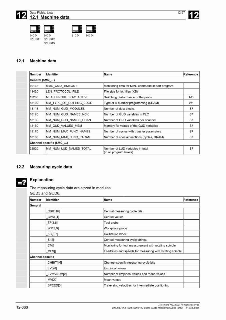
12 Data Fields, Lists 12.9712.1 Machine data 12
840 DNCU 571
840 DNCU 572NCU 573
810 D 840 Di
Siemens AG, 2002. All rights reserved12-360 SINUMERIK 840D/840Di/810D User's Guide Measuring Cycles (BNM) – 11.02 Edition
12.1 Machine data
Number Identifier Name Reference
General ($MN_...)
10132 MMC_CMD_TIMEOUT Monitoring time for MMC command in part program
11420 LEN_PROTOCOL_FILE File size for log files (KB)
13200 MEAS_PROBE_LOW_ACTIVE Switching performance of the probe M5
18102 MM_TYPE_OF_CUTTING_EDGE Type of D number programming (SRAM) W1
18118 MM_NUM_GUD_MODULES Number of data blocks S7
18120 MM_NUM_GUD_NAMES_NCK Number of GUD variables in PLC S7
18130 MM_NUM_GUD_NAMES_CHAN Number of GUD variables per channel S7
18150 MM_GUD_VALUES_MEM Memory for values of the GUD variables S7
18170 MM_NUM_MAX_FUNC_NAMES Number of cycles with transfer parameters S7
18180 MM_NUM_MAX_FUNC_PARAM Number of special functions (cycles, DRAM) S7
Channel-specific ($MC_...)
28020 MM_NUM_LUD_NAMES_TOTAL Number of LUD variables in total(in all program levels)
S7
12.2 Measuring cycle data
Explanation
The measuring cycle data are stored in modulesGUD5 and GUD6.Number Identifier Name Reference
General
_CBIT[16] Central measuring cycle bits
_CVAL[4] Central values
_TP[3,6] Tool probe
_WP[3,9] Workpiece probe
_KB[3,7] Calibration block
_SI[2] Central measuring cycle strings
_CM[] Monitoring for tool measurement with rotating spindle
_MFS[] Feedrates and speeds for measuring with rotating spindle
Channel-specific
_CHBIT[16] Channel-specific measuring cycle bits
_EV[20] Empirical values
_EVMVNUM[2] Number of empirical values and mean values
_MV[20] Mean values
_SPEED[3] Traversing velocities for intermediate positioning
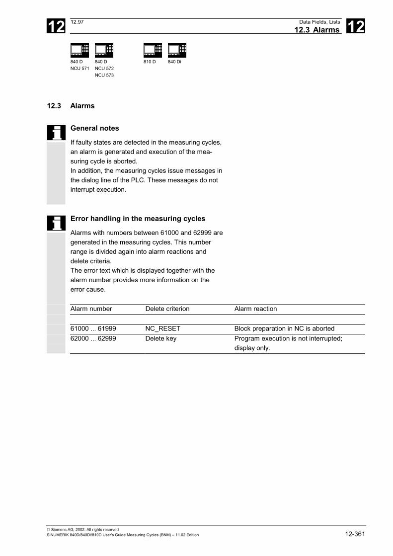
12 12.97 Data Fields, Lists12.3 Alarms 12
840 DNCU 571
840 DNCU 572NCU 573
810 D 840 Di
Siemens AG, 2002. All rights reservedSINUMERIK 840D/840Di/810D User's Guide Measuring Cycles (BNM) – 11.02 Edition 12-361
12.3 Alarms
General notes
If faulty states are detected in the measuring cycles,an alarm is generated and execution of the mea-suring cycle is aborted.In addition, the measuring cycles issue messages inthe dialog line of the PLC. These messages do notinterrupt execution.
Error handling in the measuring cycles
Alarms with numbers between 61000 and 62999 aregenerated in the measuring cycles. This numberrange is divided again into alarm reactions anddelete criteria.The error text which is displayed together with thealarm number provides more information on theerror cause.
Alarm number Delete criterion Alarm reaction
61000 ... 61999 NC_RESET Block preparation in NC is aborted62000 ... 62999 Delete key Program execution is not interrupted;
display only.
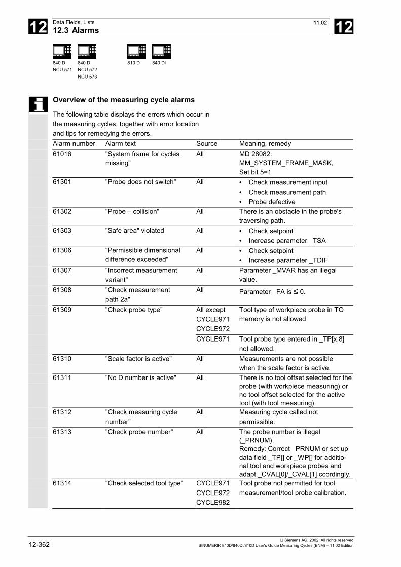
12 Data Fields, Lists 12.9712.3 Alarms 12
840 DNCU 571
840 DNCU 572NCU 573
810 D 840 Di
Siemens AG, 2002. All rights reserved12-362 SINUMERIK 840D/840Di/810D User's Guide Measuring Cycles (BNM) – 11.02 Edition
Overview of the measuring cycle alarms
The following table displays the errors which occur inthe measuring cycles, together with error locationand tips for remedying the errors.Alarm number Alarm text Source Meaning, remedy61016 "System frame for cycles
missing"All MD 28082:
MM_SYSTEM_FRAME_MASK,Set bit 5=1
61301 "Probe does not switch" All • Check measurement input• Check measurement path• Probe defective
61302 "Probe – collision" All There is an obstacle in the probe'straversing path.
61303 "Safe area" violated All • Check setpoint• Increase parameter _TSA
61306 "Permissible dimensionaldifference exceeded"
All • Check setpoint• Increase parameter _TDIF
61307 "Incorrect measurementvariant"
All Parameter _MVAR has an illegalvalue.
61308 "Check measurementpath 2a"
All Parameter _FA is ≤ 0.
61309 "Check probe type" All exceptCYCLE971CYCLE972
Tool type of workpiece probe in TOmemory is not allowed
CYCLE971 Tool probe type entered in _TP[x,8]not allowed.
61310 "Scale factor is active" All Measurements are not possiblewhen the scale factor is active.
61311 "No D number is active" All There is no tool offset selected for theprobe (with workpiece measuring) orno tool offset selected for the activetool (with tool measuring).
61312 "Check measuring cyclenumber"
All Measuring cycle called notpermissible.
61313 "Check probe number" All The probe number is illegal(_PRNUM).Remedy: Correct _PRNUM or set updata field _TP[] or _WP[] for additio-nal tool and workpiece probes andadapt _CVAL[0]/_CVAL[1] ccordingly.
61314 "Check selected tool type" CYCLE971CYCLE972CYCLE982
Tool probe not permitted for toolmeasurement/tool probe calibration.
11.02
12 12.97 Data Fields, Lists12.3 Alarms 12
840 DNCU 571
840 DNCU 572NCU 573
810 D 840 Di
Siemens AG, 2002. All rights reservedSINUMERIK 840D/840Di/810D User's Guide Measuring Cycles (BNM) – 11.02 Edition 12-363
Alarm number Alarm text Source Meaning, remedy61315 "Check tool edge position" CYCLE972
CYCLE973CYCLE974CYCLE982CYCLE994
Check tool edge position of tool(measuring probe) in TO memory
61316 "Center point and radiuscannot be determined"
CYCLE979 It is not possible to calculate acircle from the measured points.
61317 "Check parameterCYCLE116"
CYCLE979 Parameterization faulty; needs 3 or4 points for calculating the centerpoint
61318 "Check weighting factor _K" CYCLE974CYCLE977CYCLE978CYCLE979CYCLE994CYCLE998
Parameter _K is 0.
61319 "Check call parameterCYCLE114"
As 61318 Internal error measuring cycles.
61320 "Check tool number" All If tool management is active,parameter _TNUM=0, andparameter _TNAME is not assignedor the specified tool name for toolmanagement is not known.
61321 "Check ZO memory number" As 61318 The ZO with the number specifiedin _KNUM does not exist.
61322 "Check 4th digit in _KNUM" As 61318CYCLE114
4th digit position in _KNUM > 2
61323 "Check 5th digit in _KNUM" As 61318CYCLE114
5th digit position in _KNUM > 1
61324 "Check 6th digit in _KNUM" As 61318CYCLE114
6th digit position in _KNUM containsinvalid value (permissible values 1,2, 3, 4)
61325 "Check measuring axis/offset axis"
All exceptCYCLE977CYCLE979
Parameter for the measuring axis_MA has an incorrect value.
61326 "Check measuring direction" CYCLE973CYCLE976
Parameter for the measuring direc-tion _MD has an incorrect value.
61327 "Program reset necessary" All exceptCYCLE973CYCLE976
NC reset necessary
11.02
12 Data Fields, Lists 12.9712.3 Alarms 12
840 DNCU 571
840 DNCU 572NCU 573
810 D 840 Di
Siemens AG, 2002. All rights reserved12-364 SINUMERIK 840D/840Di/810D User's Guide Measuring Cycles (BNM) – 11.02 Edition
Alarm number Alarm text Source Meaning, remedy61328 "Check D number" All The D number in parameter KNUM
is 0.61329 "Check rotary axis" CYCLE998 The axis number specified in para-
meter _RA is not assigned to a name(MD 20080) or the axis is not con-figured as a rotary axis (MD 30300).
61330 "Coordinate rotation active" CYCLE972CYCLE973CYCLE974CYCLE994
Measurements are not possible ina rotated coordinate system.
61331 "Angle too large, changemeasuring axis"
CYCLE998 Parameter _STA1 is too large forthe specified measuring axis; se-lect another measuring axis.
61332 "Change position of tool tip" CYCLE971CYCLE972CYCLE982E_MT_CALE_MT_LENE_MT_RAD
Position of tool is not correct;change starting point of measure-ment.
61333 "Check calibration blocknumber"
CYCLE973 Parameter _CALNUM is too large:1. Reduce _CALNUM to a per-
missible value2. Increase maximum value
_CVAL[2] in GUD661334 "Check protection zone" CYCLE977 Parameter _SZA/_SZD too large
or too small61336 "geometry axes not available" All No geometry axes are configured;
change machine data in MD 20060.61338 "Positioning speed is zero" All Parameter _SPEED[1], _SPEED[2] in
GUD6 is 061339 "Offset factor rapid traverse
< 0"All Check parameter _SPEED[0] in
GUD6.61340 "Incorrect alarm number" All Internal error measuring cycles.61341 "Probe in active plane not
calibrated"CYCLE974CYCLE977CYCLE978CYCLE979
Calibrate probe before cycle call.
61342 "Software version entryin GUD6 incomplete or wrongformat"
CYCLE110 _SI[1] in GUD6 has no value or avalue < 3
05.98
12 12.97 Data Fields, Lists12.3 Alarms 12
840 DNCU 571
840 DNCU 572NCU 573
810 D 840 Di
Siemens AG, 2002. All rights reservedSINUMERIK 840D/840Di/810D User's Guide Measuring Cycles (BNM) – 11.02 Edition 12-365
Alarm number Alarm text Source Meaning, remedy61343 "Tool for specified tool
identifier does not exist"All Check name of tool identifier
61344 "Several tools are active" All Remove tool from other spindle.61345 "Parameterized D number
(_KNUM) too large"All Reduce D number in _KNUM,
check software or shallow Dnumber MD
61346 "Distance between startingpoint and measuring point_SETV[0] and _SETV[1] ≤ 0"
CYCLE961 Parameters _SETV[0] or _SETV[1]are not assigned or are less than 0
61347 "Angle 1st edge - 2nd edgeis 0"
CYCLE961 Parameter _INCA is 0.
61349 "Distance between toolprobe top edge and mea-suring position for tool radiusmeasurement is 0"
CYCLE971 Parameter _TP[x,9] distance betweentool probe top edge and bottom edgeis 0; relevant for radius measurement
61350 "Feedrate, speed for toolmeasurement with rotatingspindle not programmedin _MFS"
CYCLE971 Measurement feed and/or spindlespeed for tool measurement withrotating spindle not specified inGUD variable _MFS[2].
61351 "Tool length or radius is 0" CYCLE971 The length or radius for the activetool is zero.
61352 "Illegal path for log file" CYCLE106 The path specification for the logfile is incorrect.
61353 "Path for log file does notexist"
CYCLE106 The specified directory does notexist or the path indicated is in-correct.
61354 "Log file not found" CYCLE106 No name was specified for the logfile.
61355 "Incorrect file type forlog file"
CYCLE106 The file extension for the log file isincorrect.
61356 "Log file already in use" CYCLE106 The log file is already used byanother NC program.
61357 "No resources available" CYCLE106 Insufficient NC memory available,delete files.
61358 "Logging error" CYCLE106 Internal error, contact hotline61359 "Continue with RESET" CYCLE106 Internal error, contact hotline
05.98
12 Data Fields, Lists 12.9712.3 Alarms 12
840 DNCU 571
840 DNCU 572NCU 573
810 D 840 Di
Siemens AG, 2002. All rights reserved12-366 SINUMERIK 840D/840Di/810D User's Guide Measuring Cycles (BNM) – 11.02 Edition
Alarm number Alarm text Source Meaning, remedy61360 "Undefined logging job -
press RESET to continue"CYCLE106 The cycle CYCLE106 was called with
an incorrect parameter.61361 "Unable to log variable" CYCLE105 The value specified in _PROTVAL[]
cannot be logged.61362 "Too many values" CYCLE118 4th parameter for CYCLE118 is
greater than 10.61363 "Max. number of value lines
exceeded"CYCLE105 Reduce number of lines.
61364 "Check distance betweenmeasuring point 1 andmeasuring point 2.
CYCLE998 Parameter _ID is ≤ 0.
61365 "Check circular feed" CYCLE979 Parameter _RF is ≤ 0.61366 "Direction of rotation for tool
measurement with rotatingspindle in _CM[5] is notdefined"
CYCLE971 Permissible values for data field_CM[5] in the GUD6 module are3 (corresponds to M3) and 4(corresponds to M4)
61367 "The points P1 and P2, P3and P4 are identical".
CYCLE961 Various positions specified for thedifferent positions of _SETV[0...7].
61368 "The straight line defined byP1 and P2 or P3 and P4 donot produce an intersection"
CYCLE961 Various positions specified for thedifferent positions of _SETV[0...7].
61369 "Unable to uniquely determi-ne position of corner, checkparameter _SETV[0...7]"
CYCLE961 Define P1 and P2, or P3 and P4 sothat the intersection of the straightlines through these points lies outsidethe section defined by P1 and P2 orP3 and P4.
61370 "_PROTVAL[0] - _PROTVAL[5] do not contain entries"
CYCLE105CYCLE108
Assign values to _PROTVAL[0...5].
61371 "The log produced by thecolumn width and numbercolumns exceed 200 charac-ters per line"
CYCLE105CYCLE108
Reduce the column width or numberof columns.
61372(measuringcycle SW 6.2and higher)
"Selected measurementvariant requires an SPOS-capable spindle"
All Change measurement variant orcheck machine equipment
61373(measuringcycle SW 6.2and higher)
"Mono probe requires anSPOS-capable spindle"
All Check machine equipment
61401 "Probe is not responding,travel limitation by softwareend position"
CYCLE961CYCLE971CYCLE976CYCLE977CYCLE978CYCLE998
Unable to reach setpoint positionbecause software limit software endposition exceeded.
11.02
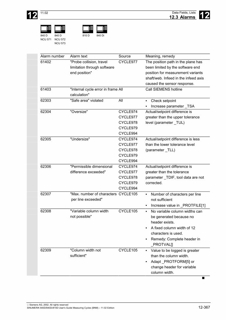
12 12.97 Data Fields, Lists12.3 Alarms 12
840 DNCU 571
840 DNCU 572NCU 573
810 D 840 Di
Siemens AG, 2002. All rights reservedSINUMERIK 840D/840Di/810D User's Guide Measuring Cycles (BNM) – 11.02 Edition 12-367
Alarm number Alarm text Source Meaning, remedy61402 "Probe collision, travel
limitation through softwareend position"
CYCLE977 The position path in the plane hasbeen limited by the software endposition for measurement variantsshaft/web. Infeed in the infeed axiscaused the sensor response.
61403 "Internal cycle error in framecalculation"
All Call SIEMENS hotline
62303 "Safe area" violated All • Check setpoint• Increase parameter _TSA
62304 "Oversize" CYCLE974CYCLE977CYCLE978CYCLE979CYCLE994
Actual/setpoint difference isgreater than the upper tolerancelevel (parameter _TUL)
62305 "Undersize" CYCLE974CYCLE977CYCLE978CYCLE979CYCLE994
Actual/setpoint difference is lessthan the lower tolerance level(parameter _TLL)
62306 "Permissible dimensionaldifference exceeded"
CYCLE974CYCLE977CYCLE978CYCLE979CYCLE994
Actual/setpoint difference isgreater than the toleranceparameter _TDIF, tool data are notcorrected.
62307 "Max. number of characters per line exceeded"
CYCLE105 • Number of characters per linenot sufficient
• Increase value in _PROTFILE[1] 62308 "Variable column width
not possible" CYCLE105 • No variable column widths can
be generated because noheader exists.
• A fixed column width of 12characters is used.
• Remedy: Complete header in_PROTVAL[]
62309 "Column width notsufficient"
CYCLE105 • Value to be logged is greaterthan the column width.
• Adapt _PROTFORM[5] orchange header for variablecolumn width.
�
11.02

12 Data Fields, Lists 12.9712.3 Alarms 12
840 DNCU 571
840 DNCU 572NCU 573
810 D 840 Di
Siemens AG, 2002. All rights reserved12-368 SINUMERIK 840D/840Di/810D User's Guide Measuring Cycles (BNM) – 11.02 Edition
Notes
Siemens AG, 2002. All rights reservedSINUMERIK 840D/840Di/810D User's Guide Measuring Cycles (BNM) – 11.02 Edition A-369
A 11.02 Appendix A
Appendix
A Overview of measuring cycle parameters.........................................................................A-371
B Abbreviations ....................................................................................................................A-405
C Terms................................................................................................................................A-407
D References .......................................................................................................................A-415
E Index .................................................................................................................................A-429
F Identifiers ..........................................................................................................................A-434

Siemens AG, 2002. All rights reservedA-370 SINUMERIK 840D/840Di/810D User's Guide Measuring Cycles (BNM) – 11.02 Edition
A Appendix 11.02 A
Siemens AG, 2002. All rights reservedSINUMERIK 840D/840Di/810D User's Guide Measuring Cycles (BNM) – 11.02 Edition A-371
A 11.02 AppendixOverview of measuring cycle parameters A
840 DNCU 571
840 DNCU 572NCU 573
810 D 840 Di
A Overview of measuring cycle parameters
Parameter definition
Parameters must be defined
Parameter is not used in the cycle
The definition of the parameter depends on the measurement variant, otherparameters, or on the machine configuration
CYCLE 961 Workpiece measurement
Automatic setup inside and outside cornerfor G17: in XY planefor G18: in ZX planefor G19: in YZ plane
Specifying distances and angles Specifying 4 pointsCornerinside
Corneroutside
Cornerinside
Corneroutside
ParametersGUD5
Type Com-parablepara-
meters840C
3 measuring points 4 measuring points
Corner inside Corner outside
_CALNUM INTEGER R12
_CORA REAL R13
_CPA REAL R20
_CPO REAL R21
_EVNUM INTEGER R11
Multiplication factor for measurement distance "2a", "a" always 1mm!_FA REAL>0
R28
only included if calculated larger thaninternal value
_ID REAL R19 Retractionin infeedaxis, incre-mental forovertravel-ing corner if_ID=0bypassesthe corner
Retractionin infeedaxis, incre-mental forovertravel-ing corner if_ID=0bypassesthe corner
Infeed of positioning depth to measuringdepth (incremental)
_INCA REAL179.5
..179.5degrees
R26 Angle from 1st edge to 2nd edge of theworkpiece (clockwise negative)
_K INTEGER R29
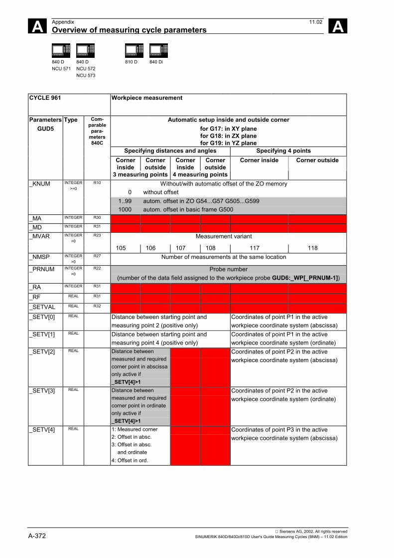
Siemens AG, 2002. All rights reservedA-372 SINUMERIK 840D/840Di/810D User's Guide Measuring Cycles (BNM) – 11.02 Edition
A Appendix 11.02Overview of measuring cycle parameters A
840 DNCU 571
840 DNCU 572NCU 573
810 D 840 Di
CYCLE 961 Workpiece measurement
Automatic setup inside and outside cornerfor G17: in XY planefor G18: in ZX planefor G19: in YZ plane
Specifying distances and angles Specifying 4 pointsCornerinside
Corneroutside
Cornerinside
Corneroutside
ParametersGUD5
Type Com-parablepara-
meters840C
3 measuring points 4 measuring points
Corner inside Corner outside
Without/with automatic offset of the ZO memory 0 without offset
_KNUM INTEGER>=0
R10
1..99 autom. offset in ZO G54...G57 G505...G599 1000 autom. offset in basic frame G500
_MA INTEGER R30
_MD INTEGER R31
_MVAR INTEGER>0
R23 Measurement variant
105 106 107 108 117 118_NMSP INTEGER
>0R27 Number of measurements at the same location
_PRNUM INTEGER>0
R22 Probe number(number of the data field assigned to the workpiece probe GUD6:_WP[_PRNUM-1])
_RA INTEGER R31
_RF REAL R31
_SETVAL REAL R32
_SETV[0] REAL Distance between starting point andmeasuring point 2 (positive only)
Coordinates of point P1 in the activeworkpiece coordinate system (abscissa)
_SETV[1] REAL Distance between starting point andmeasuring point 4 (positive only)
Coordinates of point P1 in the activeworkpiece coordinate system (ordinate)
_SETV[2] REAL Distance betweenmeasured and requiredcorner point in abscissaonly active if_SETV[4]>1
Coordinates of point P2 in the activeworkpiece coordinate system (abscissa)
_SETV[3] REAL Distance betweenmeasured and requiredcorner point in ordinateonly active if_SETV[4]>1
Coordinates of point P2 in the activeworkpiece coordinate system (ordinate)
_SETV[4] REAL 1: Measured corner2: Offset in absc.3: Offset in absc. and ordinate4: Offset in ord.
Coordinates of point P3 in the activeworkpiece coordinate system (abscissa)
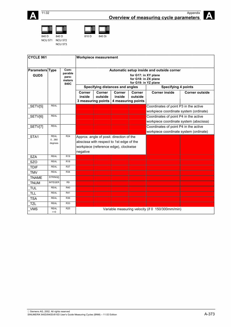
Siemens AG, 2002. All rights reservedSINUMERIK 840D/840Di/810D User's Guide Measuring Cycles (BNM) – 11.02 Edition A-373
A 11.02 AppendixOverview of measuring cycle parameters A
840 DNCU 571
840 DNCU 572NCU 573
810 D 840 Di
CYCLE 961 Workpiece measurement
Automatic setup inside and outside cornerfor G17: in XY planefor G18: in ZX planefor G19: in YZ plane
Specifying distances and angles Specifying 4 pointsCornerinside
Corneroutside
Cornerinside
Corneroutside
ParametersGUD5
Type Com-parablepara-
meters840C
3 measuring points 4 measuring points
Corner inside Corner outside
_SETV[5] REAL Coordinates of point P3 in the activeworkpiece coordinate system (ordinate)
_SETV[6] REAL Coordinates of point P4 in the activeworkpiece coordinate system (abscissa)
_SETV[7] REAL Coordinates of point P4 in the activeworkpiece coordinate system (ordinate)
_STA1 REAL0...360
degrees
R24 Approx. angle of posit. direction of theabscissa with respect to 1st edge of theworkpiece (reference edge), clockwisenegative
_SZA REAL R19
_SZO REAL R18
_TDIF REAL R37
_TMV REAL R34
_TNAME STRING[]
_TNUM INTEGER R9
_TUL REAL R40
_TLL REAL R41
_TSA REAL R36
_TZL REAL R33
_VMS REAL>=0
R25 Variable measuring velocity (if 0 150/300mm/min)
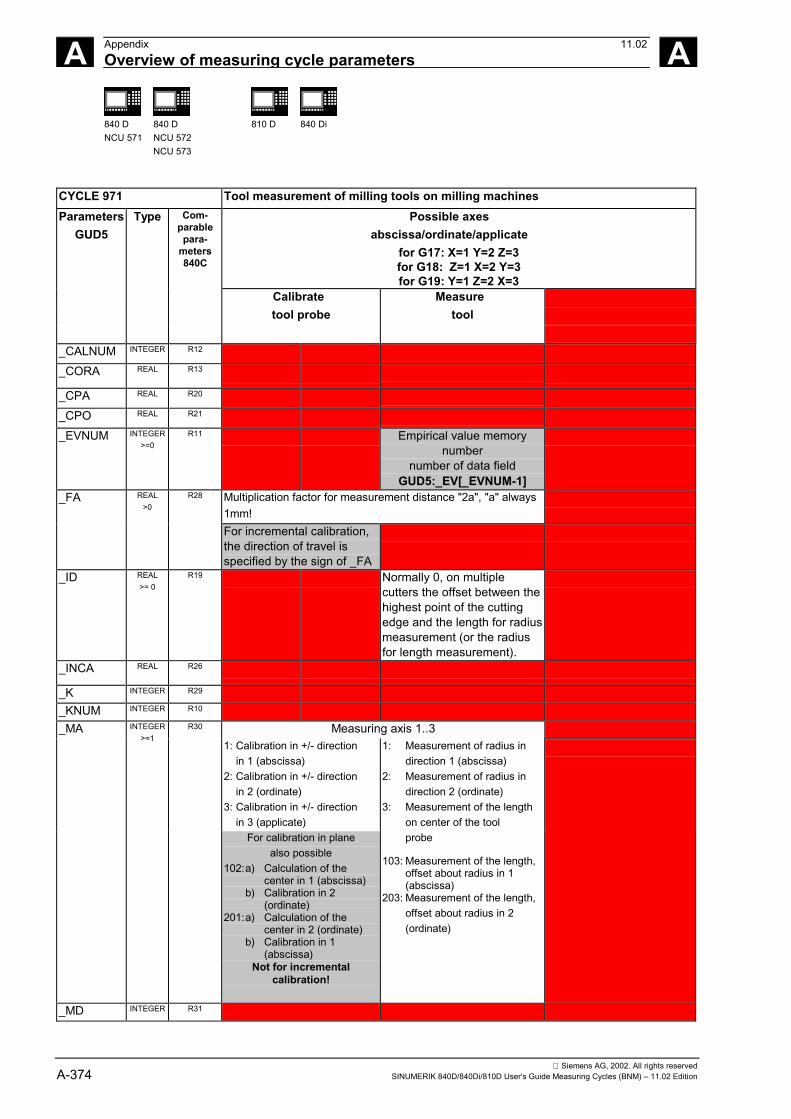
Siemens AG, 2002. All rights reservedA-374 SINUMERIK 840D/840Di/810D User's Guide Measuring Cycles (BNM) – 11.02 Edition
A Appendix 11.02Overview of measuring cycle parameters A
840 DNCU 571
840 DNCU 572NCU 573
810 D 840 Di
CYCLE 971 Tool measurement of milling tools on milling machinesPossible axes
abscissa/ordinate/applicatefor G17: X=1 Y=2 Z=3for G18: Z=1 X=2 Y=3for G19: Y=1 Z=2 X=3
ParametersGUD5
Calibrate Measuretool probe tool
Type Com-parablepara-
meters840C
_CALNUM INTEGER R12
_CORA REAL R13
_CPA REAL R20
_CPO REAL R21
_EVNUM INTEGER>=0
R11 Empirical value memorynumber
number of data fieldGUD5:_EV[_EVNUM-1]
Multiplication factor for measurement distance "2a", "a" always1mm!
_FA REAL>0
R28
For incremental calibration,the direction of travel isspecified by the sign of _FA
_ID REAL>= 0
R19 Normally 0, on multiplecutters the offset between thehighest point of the cuttingedge and the length for radiusmeasurement (or the radiusfor length measurement).
_INCA REAL R26
_K INTEGER R29
_KNUM INTEGER R10
_MA Measuring axis 1..3R30
1: Calibration in +/- directionin 1 (abscissa)
2: Calibration in +/- directionin 2 (ordinate)
3: Calibration in +/- directionin 3 (applicate)
INTEGER>=1
For calibration in planealso possible
102:a) Calculation of thecenter in 1 (abscissa)
b) Calibration in 2(ordinate)
201:a) Calculation of thecenter in 2 (ordinate)
b) Calibration in 1(abscissa)
Not for incrementalcalibration!
1: Measurement of radius indirection 1 (abscissa)
2: Measurement of radius indirection 2 (ordinate)
3: Measurement of the lengthon center of the toolprobe
103: Measurement of the length, offset about radius in 1(abscissa)
203: Measurement of the length, offset about radius in 2(ordinate)
_MD INTEGER R31
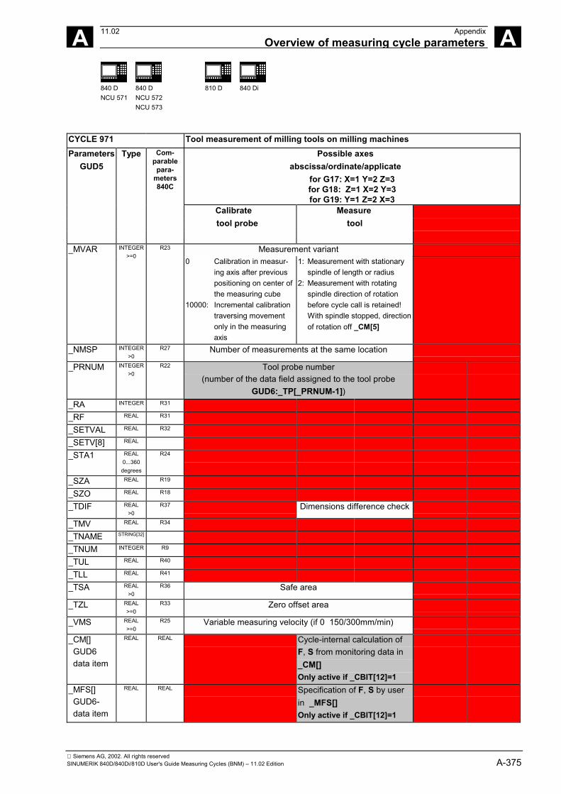
Siemens AG, 2002. All rights reservedSINUMERIK 840D/840Di/810D User's Guide Measuring Cycles (BNM) – 11.02 Edition A-375
A 11.02 AppendixOverview of measuring cycle parameters A
840 DNCU 571
840 DNCU 572NCU 573
810 D 840 Di
CYCLE 971 Tool measurement of milling tools on milling machinesPossible axes
abscissa/ordinate/applicatefor G17: X=1 Y=2 Z=3for G18: Z=1 X=2 Y=3for G19: Y=1 Z=2 X=3
ParametersGUD5
Calibrate Measure tool probe tool
Type Com-parablepara-
meters840C
Measurement variant_MVAR INTEGER>=0
R23
0 Calibration in measur-ing axis after previouspositioning on center ofthe measuring cube
10000: Incremental calibrationtraversing movementonly in the measuring axis
1: Measurement with stationary spindle of length or radius
2: Measurement with rotating spindle direction of rotation
before cycle call is retained!With spindle stopped, directionof rotation off _CM[5]
_NMSP INTEGER>0
R27 Number of measurements at the same location
_PRNUM INTEGER>0
R22 Tool probe number(number of the data field assigned to the tool probe
GUD6:_TP[_PRNUM-1])_RA INTEGER R31
_RF REAL R31
_SETVAL REAL R32
_SETV[8] REAL
_STA1 REAL0...360
degrees
R24
_SZA REAL R19
_SZO REAL R18
_TDIF REAL>0
R37 Dimensions difference check
_TMV REAL R34
_TNAME STRING[32]
_TNUM INTEGER R9
_TUL REAL R40
_TLL REAL R41
_TSA REAL>0
R36 Safe area
_TZL REAL>=0
R33 Zero offset area
_VMS REAL>=0
R25 Variable measuring velocity (if 0 150/300mm/min)
_CM[] GUD6 data item
REAL REAL Cycle-internal calculation ofF, S from monitoring data in_CM[]Only active if _CBIT[12]=1
_MFS[] GUD6- data item
REAL REAL Specification of F, S by userin _MFS[]Only active if _CBIT[12]=1
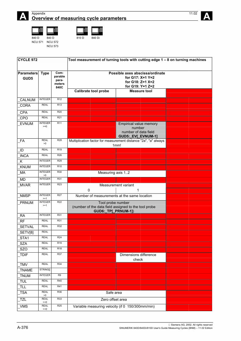
Siemens AG, 2002. All rights reservedA-376 SINUMERIK 840D/840Di/810D User's Guide Measuring Cycles (BNM) – 11.02 Edition
A Appendix 11.02Overview of measuring cycle parameters A
840 DNCU 571
840 DNCU 572NCU 573
810 D 840 Di
CYCLE 972 Tool measurement of turning tools with cutting edge 1 – 8 on turning machines
Possible axes abscissa/ordinatefor G17: X=1 Y=2for G18: Z=1 X=2for G19: Y=1 Z=2
ParametersGUD5
Type Com-parablepara-
meters840C
Calibrate tool probe Measure tool
_CALNUM INTEGER R12
_CORA REAL R13
_CPA REAL R20
_CPO REAL R21
_EVNUM INTEGER>=0
R11 Empirical value memorynumber
number of data fieldGUD5:_EV[_EVNUM-1]
_FA REAL>0
R28 Multiplication factor for measurement distance "2a", "a" always1mm!
_ID REAL R19
_INCA REAL R26
_K INTEGER R29
_KNUM INTEGER R10
_MA INTEGER>0
R30 Measuring axis 1..2
_MD INTEGER R31
Measurement variant_MVAR INTEGER R23
0 1_NMSP INTEGER
>=1R27 Number of measurements at the same location
_PRNUM INTEGER>=1
R22 Tool probe number(number of the data field assigned to the tool probe
GUD6:_TP[_PRNUM-1])_RA INTEGER R31
_RF REAL R31
_SETVAL REAL R32
_SETV[8] REAL
_STA1 REAL R24
_SZA REAL R19
_SZO REAL R18
_TDIF REAL R37 Dimensions differencecheck
_TMV REAL R34
_TNAME STRING[]
_TNUM INTEGER R9
_TUL REAL R40
_TLL REAL R41
_TSA REAL>0
R36 Safe area
_TZL REAL>=0
R33 Zero offset area
_VMS REAL>=0
R25 Variable measuring velocity (if 0 150/300mm/min)
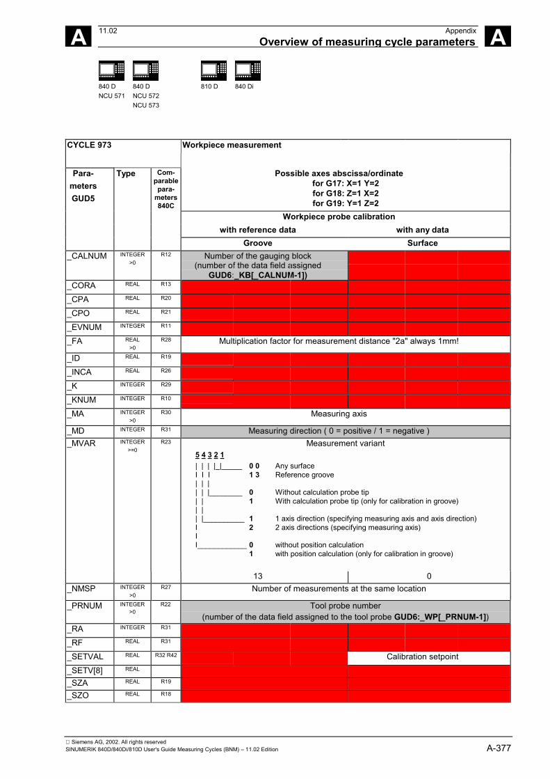
Siemens AG, 2002. All rights reservedSINUMERIK 840D/840Di/810D User's Guide Measuring Cycles (BNM) – 11.02 Edition A-377
A 11.02 AppendixOverview of measuring cycle parameters A
840 DNCU 571
840 DNCU 572NCU 573
810 D 840 Di
CYCLE 973 Workpiece measurement
Possible axes abscissa/ordinatefor G17: X=1 Y=2for G18: Z=1 X=2for G19: Y=1 Z=2
Workpiece probe calibrationwith reference data with any data
Para-metersGUD5
Type Com-parablepara-
meters840C
Groove Surface_CALNUM INTEGER
>0R12 Number of the gauging block
(number of the data field assignedGUD6:_KB[_CALNUM-1])
_CORA REAL R13
_CPA REAL R20
_CPO REAL R21
_EVNUM INTEGER R11
_FA REAL>0
R28 Multiplication factor for measurement distance "2a" always 1mm!
_ID REAL R19
_INCA REAL R26
_K INTEGER R29
_KNUM INTEGER R10
_MA INTEGER>0
R30 Measuring axis
_MD INTEGER R31 Measuring direction ( 0 = positive / 1 = negative )Measurement variant
5 4 3 2 1| | | |_|_____ 0 0 Any surfaceI I I 1 3 Reference groove| | || | |________ 0 Without calculation probe tip| | 1 With calculation probe tip (only for calibration in groove)| || |__________ 1 1 axis direction (specifying measuring axis and axis direction)I 2 2 axis directions (specifying measuring axis)II____________ 0 without position calculation
1 with position calculation (only for calibration in groove)
_MVAR INTEGER>=0
R23
13 0_NMSP INTEGER
>0R27 Number of measurements at the same location
_PRNUM INTEGER>0
R22 Tool probe number(number of the data field assigned to the tool probe GUD6:_WP[_PRNUM-1])
_RA INTEGER R31
_RF REAL R31
_SETVAL REAL R32 R42 Calibration setpoint_SETV[8] REAL
_SZA REAL R19
_SZO REAL R18
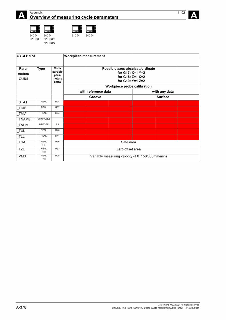
Siemens AG, 2002. All rights reservedA-378 SINUMERIK 840D/840Di/810D User's Guide Measuring Cycles (BNM) – 11.02 Edition
A Appendix 11.02Overview of measuring cycle parameters A
840 DNCU 571
840 DNCU 572NCU 573
810 D 840 Di
CYCLE 973 Workpiece measurement
Possible axes abscissa/ordinatefor G17: X=1 Y=2for G18: Z=1 X=2for G19: Y=1 Z=2
Workpiece probe calibrationwith reference data with any data
Para-metersGUD5
Type Com-parablepara-
meters840C
Groove Surface_STA1 REAL R24
_TDIF REAL R37
_TMV REAL R34
_TNAME STRING[32]
_TNUM INTEGER R9
_TUL REAL R40
_TLL REAL R41
_TSA REAL>0
R36 Safe area
_TZL REAL>=0
R33 Zero offset area
_VMS REAL>=0
R25 Variable measuring velocity (if 0 150/300mm/min)
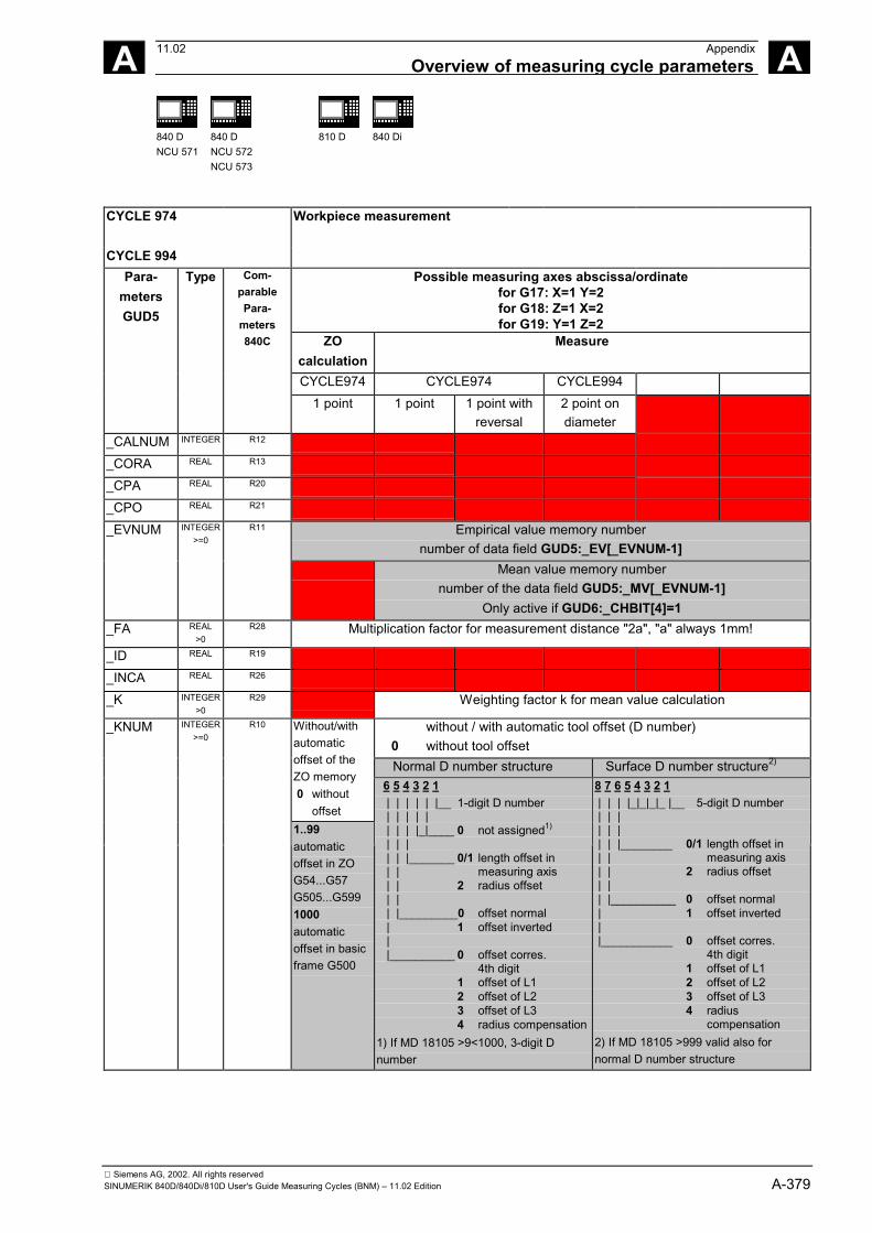
Siemens AG, 2002. All rights reservedSINUMERIK 840D/840Di/810D User's Guide Measuring Cycles (BNM) – 11.02 Edition A-379
A 11.02 AppendixOverview of measuring cycle parameters A
840 DNCU 571
840 DNCU 572NCU 573
810 D 840 Di
CYCLE 974 Workpiece measurement
CYCLE 994Possible measuring axes abscissa/ordinate
for G17: X=1 Y=2for G18: Z=1 X=2for G19: Y=1 Z=2
ZOcalculation
Measure
CYCLE974 CYCLE974 CYCLE994
Para-metersGUD5
Type Com-parablePara-
meters840C
1 point 1 point 1 point withreversal
2 point ondiameter
_CALNUM INTEGER R12
_CORA REAL R13
_CPA REAL R20
_CPO REAL R21
Empirical value memory numbernumber of data field GUD5:_EV[_EVNUM-1]
_EVNUM INTEGER>=0
R11
Mean value memory numbernumber of the data field GUD5:_MV[_EVNUM-1]
Only active if GUD6:_CHBIT[4]=1_FA REAL
>0R28 Multiplication factor for measurement distance "2a", "a" always 1mm!
_ID REAL R19
_INCA REAL R26
_K INTEGER>0
R29 Weighting factor k for mean value calculation
without / with automatic tool offset (D number) 0 without tool offset
Normal D number structure Surface D number structure2)
Without/withautomaticoffset of theZO memory 0 without
offset
_KNUM INTEGER>=0
R10
1..99automaticoffset in ZOG54...G57G505...G5991000automaticoffset in basicframe G500
6 5 4 3 2 1 | | | | | |__ 1-digit D number | | | | | | | | |_|____ 0 not assigned1)
| | | | | |_______ 0/1 length offset in | | measuring axis | | 2 radius offset | | | |_________0 offset normal | 1 offset inverted | |__________ 0 offset corres.
4th digit1 offset of L12 offset of L23 offset of L34 radius compensation
1) If MD 18105 >9<1000, 3-digit Dnumber
8 7 6 5 4 3 2 1 | | | |_|_|_|_ |__ 5-digit D number | | | | | | | | |________ 0/1 length offset in | | measuring axis | | 2 radius offset | | | |__________ 0 offset normal | 1 offset inverted | |___________ 0 offset corres.
4th digit1 offset of L12 offset of L23 offset of L34 radius
compensation2) If MD 18105 >999 valid also fornormal D number structure
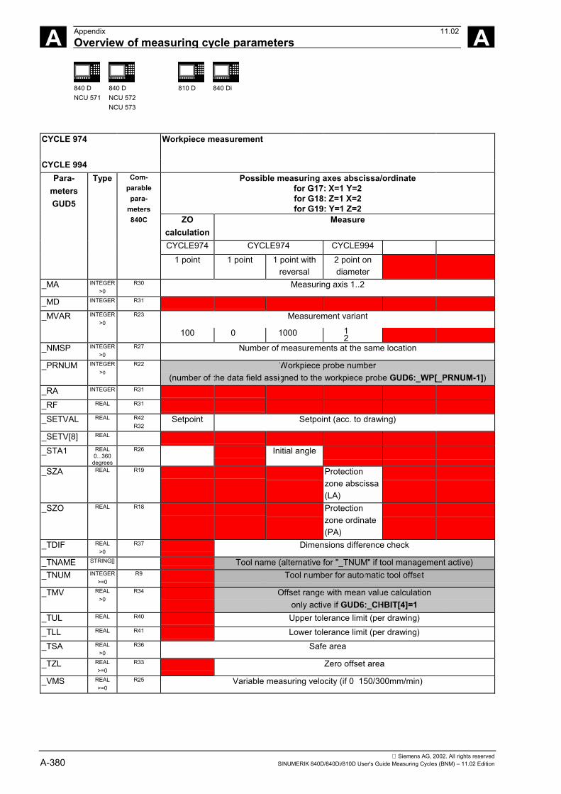
Siemens AG, 2002. All rights reservedA-380 SINUMERIK 840D/840Di/810D User's Guide Measuring Cycles (BNM) – 11.02 Edition
A Appendix 11.02Overview of measuring cycle parameters A
840 DNCU 571
840 DNCU 572NCU 573
810 D 840 Di
CYCLE 974 Workpiece measurement
CYCLE 994Possible measuring axes abscissa/ordinate
for G17: X=1 Y=2for G18: Z=1 X=2for G19: Y=1 Z=2
ZOcalculation
Measure
CYCLE974 CYCLE974 CYCLE994
Para-metersGUD5
Type Com-parablepara-
meters840C
1 point 1 point 1 point withreversal
2 point ondiameter
_MA INTEGER>0
R30 Measuring axis 1..2
_MD INTEGER R31
_MVAR INTEGER>0
R23 Measurement variant
100 0 1000 12
_NMSP INTEGER>0
R27 Number of measurements at the same location
_PRNUM INTEGER>0
R22 Workpiece probe number(number of the data field assigned to the workpiece probe GUD6:_WP[_PRNUM-1])
_RA INTEGER R31
_RF REAL R31
_SETVAL REAL R42R32
Setpoint Setpoint (acc. to drawing)
_SETV[8] REAL
_STA1 REAL0...360
degrees
R26 Initial angle
_SZA REAL R19 Protectionzone abscissa(LA)
_SZO REAL R18 Protectionzone ordinate(PA)
_TDIF REAL>0
R37 Dimensions difference check
_TNAME STRING[] Tool name (alternative for "_TNUM" if tool management active)_TNUM INTEGER
>=0R9 Tool number for automatic tool offset
_TMV REAL>0
R34 Offset range with mean value calculationonly active if GUD6:_CHBIT[4]=1
_TUL REAL R40 Upper tolerance limit (per drawing)_TLL REAL R41 Lower tolerance limit (per drawing)_TSA REAL
>0R36 Safe area
_TZL REAL>=0
R33 Zero offset area
_VMS REAL>=0
R25 Variable measuring velocity (if 0 150/300mm/min)
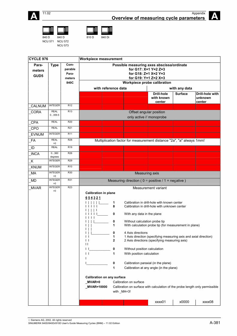
Siemens AG, 2002. All rights reservedSINUMERIK 840D/840Di/810D User's Guide Measuring Cycles (BNM) – 11.02 Edition A-381
A 11.02 AppendixOverview of measuring cycle parameters A
840 DNCU 571
840 DNCU 572NCU 573
810 D 840 Di
CYCLE 976 Workpiece measurementPossible measuring axes abscissa/ordinate
for G17: X=1 Y=2 Z=3for G18: Z=1 X=2 Y=3for G19: Y=1 Z=2 X=3
Workpiece probe calibrationwith reference data with any data
Para-metersGUD5
Type Com-parablePara-
meters840C
Drill-holewith known
center
Surface Drill-hole withunknowncenter
_CALNUM INTEGER R12
_CORA REAL0...359.5
R13 Offset angular positiononly active if monoprobe
_CPA REAL R20
_CPO REAL R21
_EVNUM INTEGER R11
_FA REAL>0
R28 Multiplication factor for measurement distance "2a", "a" always 1mm!
_ID REAL R19
_INCA 0...360degrees
R26
_K INTEGER R29
_KNUM INTEGER R10
_MA INTEGER>0
R30 Measuring axis
_MD INTEGER>0
R31 Measuring direction ( 0 = positive / 1 = negative )
_MVAR INTEGER>0
R23 Measurement variantCalibration in plane6 5 4 3 2 1I | | | | |_____ 1 Calibration in drill-hole with known centerI I I I I 8 Calibration in drill-hole with unknown centerI | | | II I I I I______ 0 With any data in the planeI I I II | | |________ 0 Without calculation probe tipI | | 1 With calculation probe tip (for measurement in plane)I | |I | |__________ 0 4 Axis directionsI I 1 1 Axis direction (specifying measuring axis and axial direction)I I 2 2 Axis directions (specifying measuring axis)I II I____________ 0 Without position calculationI I 1 With position calculationII____________ 0 Calibration paraxial (in the plane)
1 Calibration at any angle (in the plane)
Calibration on any surface_MVAR=0 Calibration on surface_MVAR=10000 Calibration on surface with calculation of the probe length only permissible
with _MA=3!
xxxx01 x0000 xxxx08
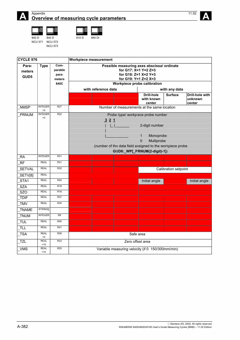
Siemens AG, 2002. All rights reservedA-382 SINUMERIK 840D/840Di/810D User's Guide Measuring Cycles (BNM) – 11.02 Edition
A Appendix 11.02Overview of measuring cycle parameters A
840 DNCU 571
840 DNCU 572NCU 573
810 D 840 Di
CYCLE 976 Workpiece measurementPossible measuring axes abscissa/ ordinate
for G17: X=1 Y=2 Z=3for G18: Z=1 X=2 Y=3for G19: Y=1 Z=2 X=3
Workpiece probe calibrationwith reference data with any data
Para-metersGUD5
Type Com-parablepara-
meters840C
Drill-holewith known
center
Surface Drill-hole withunknowncenter
_NMSP INTEGER>0
R27 Number of measurements at the same location
_PRNUM INTEGER>0
R22 Probe type/ workpiece probe number 3 2 1 | |_ |_______ 2-digit number | |___________ 1 Monoprobe 0 Multiprobe
(number of the data field assigned to the workpiece probeGUD6:_WP[_PRNUM(2-digit)-1])
_RA INTEGER R31
_RF REAL R31
_SETVAL REAL R32 Calibration setpoint
_SETV[8] REAL
_STA1 REAL R24 Initial angle Initial angle_SZA REAL R19
_SZO REAL R18
_TDIF REAL R37
_TMV REAL R34
_TNAME STRING[]
_TNUM INTEGER R9
_TUL REAL R40
_TLL REAL R41
_TSA REAL>0
R36 Safe area
_TZL REAL>=0
R33 Zero offset area
_VMS REAL>=0
R25 Variable measuring velocity (if 0 150/300mm/min)
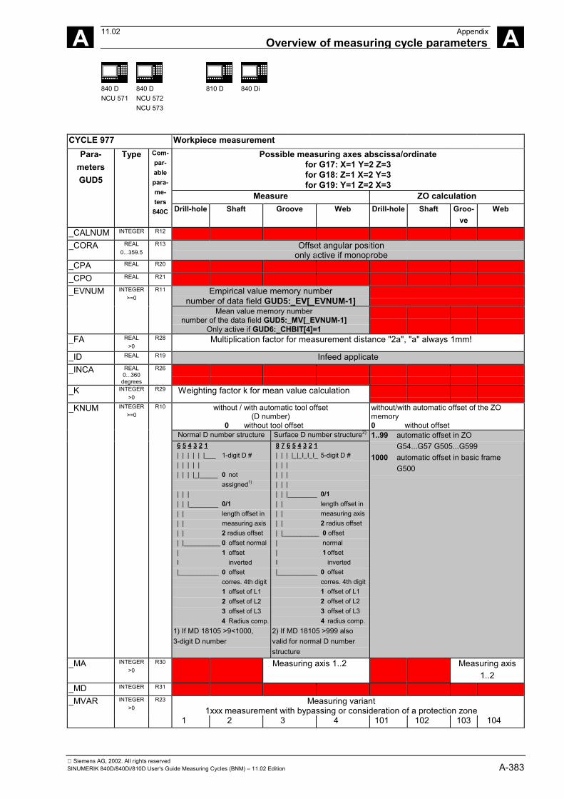
Siemens AG, 2002. All rights reservedSINUMERIK 840D/840Di/810D User's Guide Measuring Cycles (BNM) – 11.02 Edition A-383
A 11.02 AppendixOverview of measuring cycle parameters A
840 DNCU 571
840 DNCU 572NCU 573
810 D 840 Di
CYCLE 977 Workpiece measurementPossible measuring axes abscissa/ordinate
for G17: X=1 Y=2 Z=3for G18: Z=1 X=2 Y=3for G19: Y=1 Z=2 X=3
Measure ZO calculation
Para-metersGUD5
Type Com-par-ablepara-me-ters840C Drill-hole Shaft Groove Web Drill-hole Shaft Groo-
veWeb
_CALNUM INTEGER R12
_CORA REAL0...359.5
R13 Offset angular positiononly active if monoprobe
_CPA REAL R20
_CPO REAL R21
Empirical value memory numbernumber of data field GUD5:_EV[_EVNUM-1]
_EVNUM INTEGER>=0
R11
Mean value memory numbernumber of the data field GUD5:_MV[_EVNUM-1]
Only active if GUD6:_CHBIT[4]=1_FA REAL
>0R28 Multiplication factor for measurement distance "2a", "a" always 1mm!
_ID REAL R19 Infeed applicate_INCA REAL
0...360degrees
R26
_K INTEGER>0
R29 Weighting factor k for mean value calculation
without / with automatic tool offset(D number)
0 without tool offset
without/with automatic offset of the ZOmemory0 without offset
Normal D number structure Surface D number structure2)
_KNUM INTEGER>=0
R10
6 5 4 3 2 1 | | | | | |___ 1-digit D # | | | | | | | | |_|_____ 0 not
assigned1)
| | | | | |________ 0/1 | | length offset in | | measuring axis | | 2 radius offset | |__________ 0 offset normal | 1 offset I inverted |___________ 0 offset
corres. 4th digit1 offset of L12 offset of L23 offset of L34 Radius comp.
1) If MD 18105 >9<1000,3-digit D number
8 7 6 5 4 3 2 1 | | | | | I I I_ 5-digit D # | | | | | | | | | | | |________ 0/1 | | length offset in | | measuring axis | | 2 radius offset | |__________ 0 offset | normal | 1 offset I inverted |___________ 0 offset
corres. 4th digit1 offset of L12 offset of L23 offset of L34 radius comp.
2) If MD 18105 >999 alsovalid for normal D numberstructure
1..99 automatic offset in ZOG54...G57 G505...G599
1000 automatic offset in basic frame G500
_MA INTEGER>0
R30 Measuring axis 1..2 Measuring axis1..2
_MD INTEGER R31
_MVAR INTEGER>0
R23 Measuring variant1xxx measurement with bypassing or consideration of a protection zone
1 2 3 4 101 102 103 104
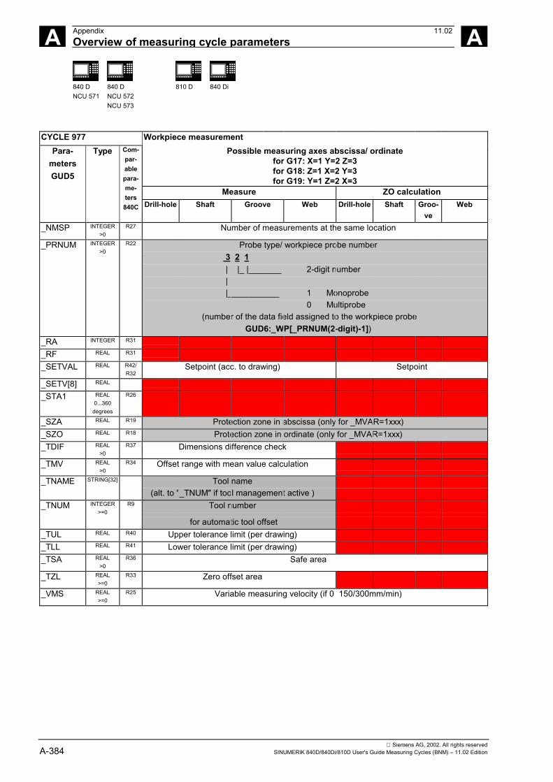
Siemens AG, 2002. All rights reservedA-384 SINUMERIK 840D/840Di/810D User's Guide Measuring Cycles (BNM) – 11.02 Edition
A Appendix 11.02Overview of measuring cycle parameters A
840 DNCU 571
840 DNCU 572NCU 573
810 D 840 Di
CYCLE 977 Workpiece measurementPossible measuring axes abscissa/ ordinate
for G17: X=1 Y=2 Z=3for G18: Z=1 X=2 Y=3for G19: Y=1 Z=2 X=3
Measure ZO calculation
Para-metersGUD5
Type Com-par-ablepara-me-ters840C Drill-hole Shaft Groove Web Drill-hole Shaft Groo-
veWeb
_NMSP INTEGER>0
R27 Number of measurements at the same location
_PRNUM INTEGER>0
R22 Probe type/ workpiece probe number 3 2 1 | |_ |_______ 2-digit number | |___________ 1 Monoprobe 0 Multiprobe
(number of the data field assigned to the workpiece probeGUD6:_WP[_PRNUM(2-digit)-1])
_RA INTEGER R31
_RF REAL R31
_SETVAL REAL R42/R32
Setpoint (acc. to drawing) Setpoint
_SETV[8] REAL
_STA1 REAL0...360
degrees
R26
_SZA REAL R19 Protection zone in abscissa (only for _MVAR=1xxx)_SZO REAL R18 Protection zone in ordinate (only for _MVAR=1xxx)_TDIF REAL
>0R37 Dimensions difference check
_TMV REAL>0
R34 Offset range with mean value calculation
_TNAME STRING[32] Tool name(alt. to "_TNUM" if tool management active )
_TNUM INTEGER>=0
R9 Tool number
for automatic tool offset_TUL REAL R40 Upper tolerance limit (per drawing)_TLL REAL R41 Lower tolerance limit (per drawing)_TSA REAL
>0R36 Safe area
_TZL REAL>=0
R33 Zero offset area
_VMS REAL>=0
R25 Variable measuring velocity (if 0 150/300mm/min)
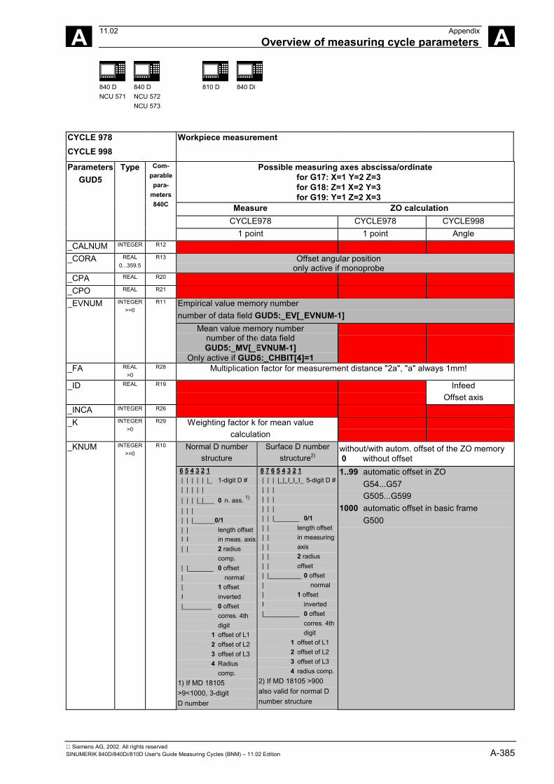
Siemens AG, 2002. All rights reservedSINUMERIK 840D/840Di/810D User's Guide Measuring Cycles (BNM) – 11.02 Edition A-385
A 11.02 AppendixOverview of measuring cycle parameters A
840 DNCU 571
840 DNCU 572NCU 573
810 D 840 Di
CYCLE 978 Workpiece measurementCYCLE 998
Possible measuring axes abscissa/ordinatefor G17: X=1 Y=2 Z=3for G18: Z=1 X=2 Y=3for G19: Y=1 Z=2 X=3
Measure ZO calculationCYCLE978 CYCLE978 CYCLE998
ParametersGUD5
Type Com-parablepara-
meters840C
1 point 1 point Angle_CALNUM INTEGER R12
_CORA REAL0...359.5
R13 Offset angular positiononly active if monoprobe
_CPA REAL R20
_CPO REAL R21
_EVNUM INTEGER>=0
R11 Empirical value memory numbernumber of data field GUD5:_EV[_EVNUM-1]
Mean value memory numbernumber of the data fieldGUD5:_MV[_EVNUM-1]
Only active if GUD6:_CHBIT[4]=1_FA REAL
>0R28 Multiplication factor for measurement distance "2a", "a" always 1mm!
_ID REAL R19 InfeedOffset axis
_INCA INTEGER R26
_K INTEGER>0
R29 Weighting factor k for mean valuecalculation
INTEGER>=0
Normal D numberstructure
Surface D numberstructure2)
without/with autom. offset of the ZO memory 0 without offset
_KNUM R10
6 5 4 3 2 1 | | | | | |_ 1-digit D # | | | | | | | | |_|___ 0 n. ass. 1)
| | | | | |______0/1 | | length offset I I in meas. axis | | 2 radius
comp. | |_______ 0 offset | normal | 1 offset I inverted |________ 0 offset
corres. 4th digit
1 offset of L12 offset of L23 offset of L34 Radius
comp.1) If MD 18105>9<1000, 3-digitD number
8 7 6 5 4 3 2 1 | | | | | I I I_ 5-digit D # | | | | | | | | | | | |_______ 0/1 | | length offset | | in measuring | | axis | | 2 radius | | offset | |_________ 0 offset | normal | 1 offset I inverted |__________ 0 offset
corres. 4th digit
1 offset of L12 offset of L23 offset of L34 radius comp.
2) If MD 18105 >900also valid for normal Dnumber structure
1..99 automatic offset in ZOG54...G57G505...G599
1000 automatic offset in basic frameG500
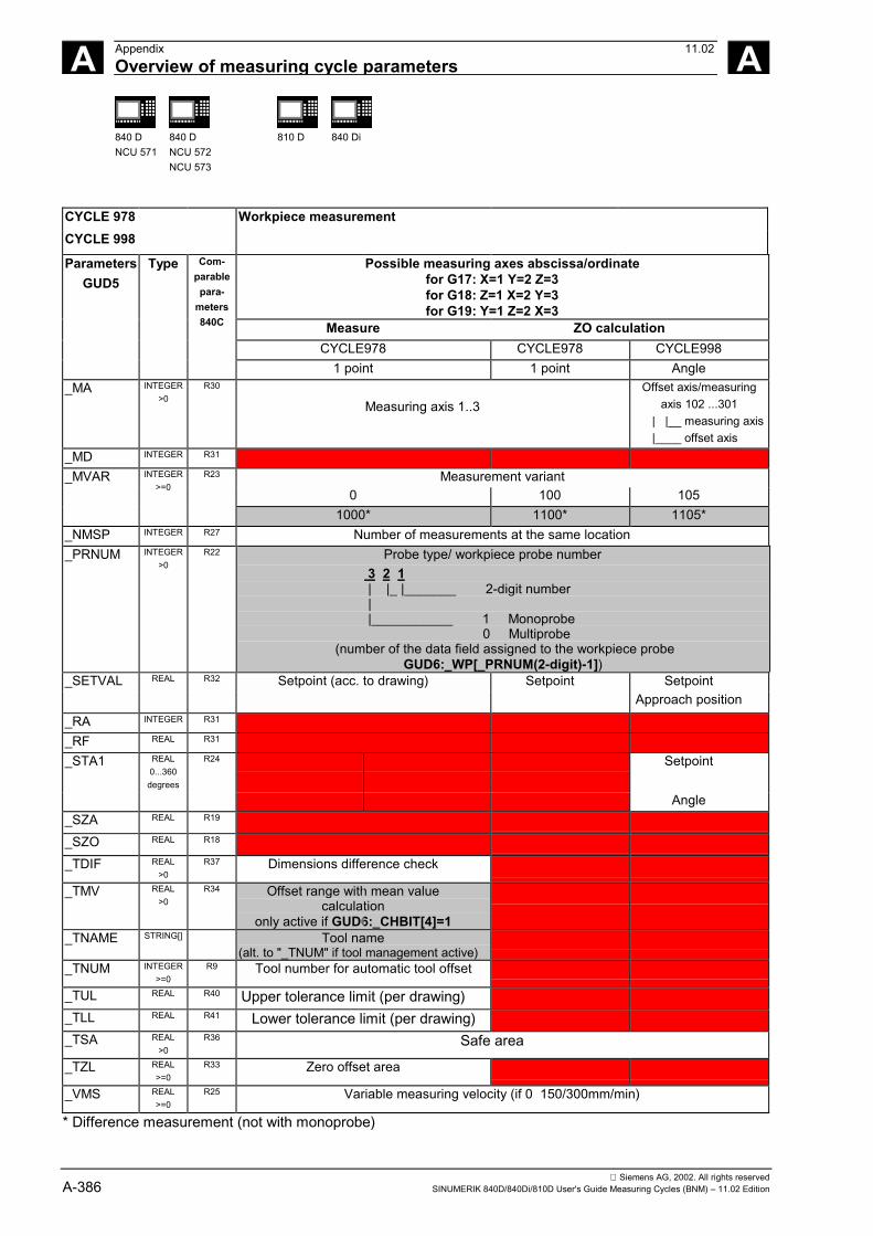
Siemens AG, 2002. All rights reservedA-386 SINUMERIK 840D/840Di/810D User's Guide Measuring Cycles (BNM) – 11.02 Edition
A Appendix 11.02Overview of measuring cycle parameters A
840 DNCU 571
840 DNCU 572NCU 573
810 D 840 Di
CYCLE 978 Workpiece measurementCYCLE 998
Possible measuring axes abscissa/ordinatefor G17: X=1 Y=2 Z=3for G18: Z=1 X=2 Y=3for G19: Y=1 Z=2 X=3
Measure ZO calculationCYCLE978 CYCLE978 CYCLE998
ParametersGUD5
Type Com-parablepara-
meters840C
1 point 1 point Angle_MA INTEGER
>0R30
Measuring axis 1..3Offset axis/measuring
axis 102 ...301 | |__ measuring axis |____ offset axis
_MD INTEGER R31
Measurement variant0 100 105
_MVAR INTEGER>=0
R23
1000* 1100* 1105*_NMSP INTEGER R27 Number of measurements at the same location_PRNUM INTEGER
>0R22 Probe type/ workpiece probe number
3 2 1 | |_ |_______ 2-digit number | |___________ 1 Monoprobe 0 Multiprobe
(number of the data field assigned to the workpiece probeGUD6:_WP[_PRNUM(2-digit)-1])
_SETVAL REAL R32 Setpoint (acc. to drawing) Setpoint SetpointApproach position
_RA INTEGER R31
_RF REAL R31
_STA1 REAL0...360
degrees
R24 Setpoint
Angle_SZA REAL R19
_SZO REAL R18
_TDIF REAL>0
R37 Dimensions difference check
_TMV REAL>0
R34 Offset range with mean valuecalculation
only active if GUD6:_CHBIT[4]=1_TNAME STRING[] Tool name
(alt. to "_TNUM" if tool management active)_TNUM INTEGER
>=0R9 Tool number for automatic tool offset
_TUL REAL R40 Upper tolerance limit (per drawing)_TLL REAL R41 Lower tolerance limit (per drawing)_TSA REAL
>0R36 Safe area
_TZL REAL>=0
R33 Zero offset area
_VMS REAL>=0
R25 Variable measuring velocity (if 0 150/300mm/min)
* Difference measurement (not with monoprobe)
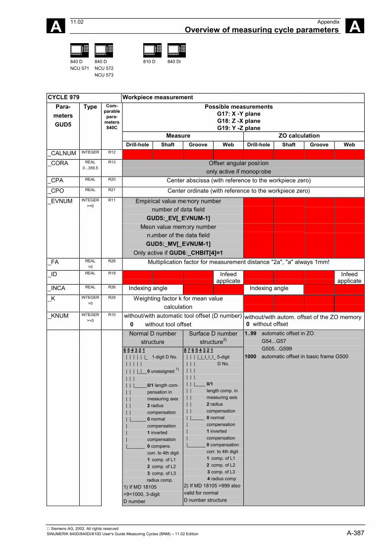
Siemens AG, 2002. All rights reservedSINUMERIK 840D/840Di/810D User's Guide Measuring Cycles (BNM) – 11.02 Edition A-387
A 11.02 AppendixOverview of measuring cycle parameters A
840 DNCU 571
840 DNCU 572NCU 573
810 D 840 Di
CYCLE 979 Workpiece measurementPossible measurements
G17: X -Y planeG18: Z -X planeG19: Y -Z plane
Measure ZO calculation
Para-metersGUD5
Type Com-parablepara-
meters840C
Drill-hole Shaft Groove Web Drill-hole Shaft Groove Web_CALNUM INTEGER R12
_CORA REAL0...359.5
R13 Offset angular positiononly active if monoprobe
_CPA REAL R20 Center abscissa (with reference to the workpiece zero)
_CPO REAL R21 Center ordinate (with reference to the workpiece zero)
_EVNUM INTEGER>=0
R11 Empirical value memory numbernumber of data field
GUD5:_EV[_EVNUM-1]Mean value memory number
number of the data fieldGUD5:_MV[_EVNUM-1]
Only active if GUD6:_CHBIT[4]=1_FA REAL
>0R28 Multiplication factor for measurement distance "2a", "a" always 1mm!
_ID REAL R19 Infeedapplicate
Infeedapplicate
_INCA REAL R26 Indexing angle Indexing angle
_K INTEGER>0
R29 Weighting factor k for mean valuecalculation
_KNUM INTEGER>=0
R10 without/with automatic tool offset (D number) 0 without tool offset
without/with autom. offset of the ZO memory 0 without offset
Normal D numberstructure
Surface D numberstructure2)
6 5 4 3 2 1 | | | | | |_ 1-digit D No. | | | | | | | | |_|__0 unassigned 1)
| | | | | |_____0/1 length com- | | pensation in | | measuring axis | | 2 radius | | compensation | |______ 0 normal | compensation | 1 inverted | compensation |_______ 0 compens.
corr. to 4th digit1 comp. of L12 comp. of L23 comp. of L3radius comp.
1) If MD 18105>9<1000, 3-digitD number
8 7 6 5 4 3 2 1 | | | | | I I I_ 5-digit | | | D No. | | | | | | | | |____ 0/1 | | length comp. in | | measuring axis | | 2 radius | | compensation | |_____ 0 normal | compensation | 1 inverted | compensation |_______ 0 compensation
corr. to 4th digit1 comp. of L12 comp. of L23 comp. of L34 radius comp
2) If MD 18105 >999 alsovalid for normalD number structure
1..99 automatic offset in ZOG54...G57G505...G599
1000 automatic offset in basic frame G500
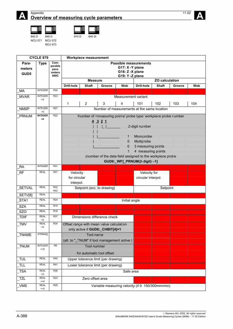
Siemens AG, 2002. All rights reservedA-388 SINUMERIK 840D/840Di/810D User's Guide Measuring Cycles (BNM) – 11.02 Edition
A Appendix 11.02Overview of measuring cycle parameters A
840 DNCU 571
840 DNCU 572NCU 573
810 D 840 Di
CYCLE 979 Workpiece measurementPossible measurements
G17: X -Y planeG18: Z -X planeG19: Y -Z plane
Measure ZO calculation
Para-metersGUD5
Type Com-parablepara-
meters840C
Drill-hole Shaft Groove Web Drill-hole Shaft Groove Web_MA INTEGER R30
_MVAR INTEGER>0
R23 Measurement variant
1 2 3 4 101 102 103 104_NMSP INTEGER
>0R27 Number of measurements at the same location
_PRNUM INTEGER>0
R22 Number of >measuring points/ probe type/ workpiece probe number 4 3 2 1 | | |_ |_______ 2-digit number | | | |___________ 1 Monoprobe | 0 Multiprobe |_____________ 0 3 measuring points 1 4 measuring points
(number of the data field assigned to the workpiece probeGUD6:_WP[_PRNUM(2-digit) –1]
_RA INTEGER R31
_RF REAL R31 Velocityfor circular
interpol.
Velocity forcircular interpol.
_SETVAL REAL R32R42
Setpoint (acc. to drawing) Setpoint
_SETV[8] REAL
_STA1 REAL R24 Initial angle
_SZA REAL R19
_SZO REAL R18
_TDIF REAL>0
R37 Dimensions difference check
_TMV REAL>0
R34 Offset range with mean value calculationonly active if GUD6:_CHBIT[4]=1
_TNAME STRING[] Tool name(alt. to "_TNUM" if tool management active )
_TNUM INTEGER>=0
R9 Tool number
for automatic tool offset_TUL REAL R40 Upper tolerance limit (per drawing)
_TLL REAL R41 Lower tolerance limit (per drawing)
_TSA REAL>0
R36 Safe area
_TZL REAL>=0
R33 Zero offset area
_VMS REAL>=0
R25 Variable measuring velocity (if 0 150/300mm/min)
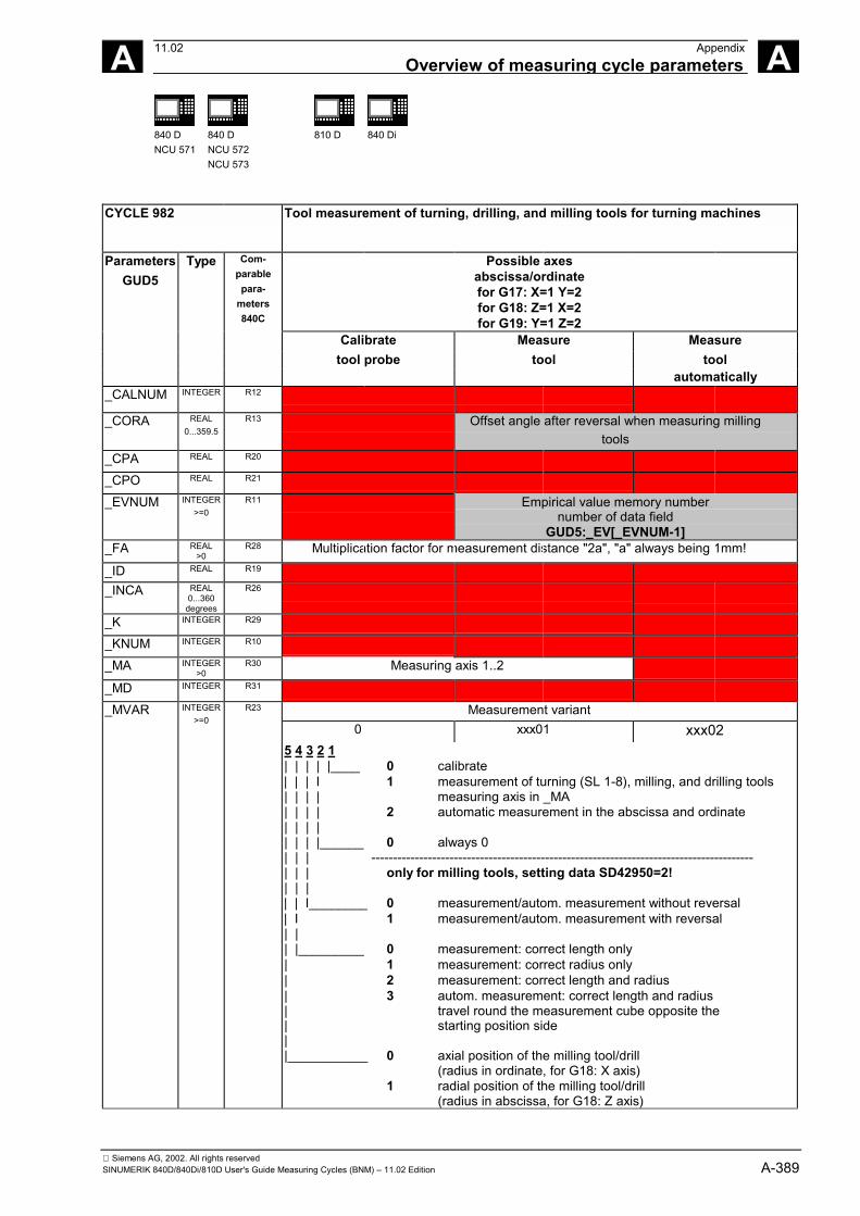
Siemens AG, 2002. All rights reservedSINUMERIK 840D/840Di/810D User's Guide Measuring Cycles (BNM) – 11.02 Edition A-389
A 11.02 AppendixOverview of measuring cycle parameters A
840 DNCU 571
840 DNCU 572NCU 573
810 D 840 Di
CYCLE 982 Tool measurement of turning, drilling, and milling tools for turning machines
Possible axesabscissa/ordinatefor G17: X=1 Y=2for G18: Z=1 X=2for G19: Y=1 Z=2
Calibrate Measure Measuretool probe tool tool
ParametersGUD5
Type Com-parablepara-
meters840C
automatically_CALNUM INTEGER R12
_CORA REAL0...359.5
R13 Offset angle after reversal when measuring millingtools
_CPA REAL R20
_CPO REAL R21
_EVNUM INTEGER>=0
R11 Empirical value memory numbernumber of data field
GUD5:_EV[_EVNUM-1]_FA REAL
>0R28 Multiplication factor for measurement distance "2a", "a" always being 1mm!
_ID REAL R19
_INCA REAL0...360
degrees
R26
_K INTEGER R29
_KNUM INTEGER R10
_MA INTEGER>0
R30 Measuring axis 1..2
_MD INTEGER R31
_MVAR Measurement variant0 xxx01 xxx02
INTEGER>=0
R23
5 4 3 2 1| | | | |____ 0 calibrate| | | I 1 measurement of turning (SL 1-8), milling, and drilling tools| | | | measuring axis in _MA| | | | 2 automatic measurement in the abscissa and ordinate| | | || | | |______ 0 always 0| | | ----------------------------------------------------------------------------------------| | | only for milling tools, setting data SD42950=2!| | || | I________ 0 measurement/autom. measurement without reversal| I 1 measurement/autom. measurement with reversal| || |_________ 0 measurement: correct length only| 1 measurement: correct radius only| 2 measurement: correct length and radius| 3 autom. measurement: correct length and radius| travel round the measurement cube opposite the| starting position side||___________ 0 axial position of the milling tool/drill
(radius in ordinate, for G18: X axis)1 radial position of the milling tool/drill
(radius in abscissa, for G18: Z axis)
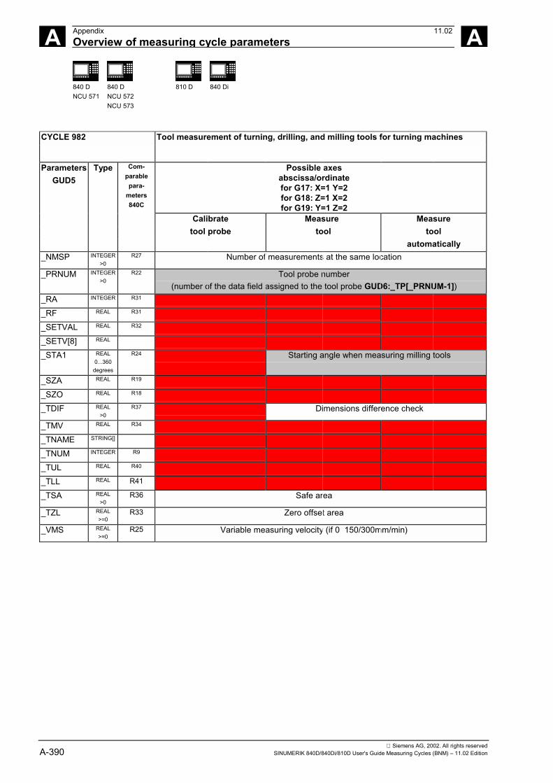
Siemens AG, 2002. All rights reservedA-390 SINUMERIK 840D/840Di/810D User's Guide Measuring Cycles (BNM) – 11.02 Edition
A Appendix 11.02Overview of measuring cycle parameters A
840 DNCU 571
840 DNCU 572NCU 573
810 D 840 Di
CYCLE 982 Tool measurement of turning, drilling, and milling tools for turning machines
Possible axesabscissa/ordinatefor G17: X=1 Y=2for G18: Z=1 X=2for G19: Y=1 Z=2
Calibrate Measure Measuretool probe tool tool
ParametersGUD5
Type Com-parablepara-
meters840C
automatically_NMSP INTEGER
>0R27 Number of measurements at the same location
_PRNUM INTEGER>0
R22 Tool probe number(number of the data field assigned to the tool probe GUD6:_TP[_PRNUM-1])
_RA INTEGER R31
_RF REAL R31
_SETVAL REAL R32
_SETV[8] REAL
_STA1 REAL0...360
degrees
R24 Starting angle when measuring milling tools
_SZA REAL R19
_SZO REAL R18
_TDIF REAL>0
R37 Dimensions difference check
_TMV REAL R34
_TNAME STRING[]
_TNUM INTEGER R9
_TUL REAL R40
_TLL REAL R41
_TSA REAL>0
R36 Safe area
_TZL REAL>=0
R33 Zero offset area
_VMS REAL>=0
R25 Variable measuring velocity (if 0 150/300mm/min)
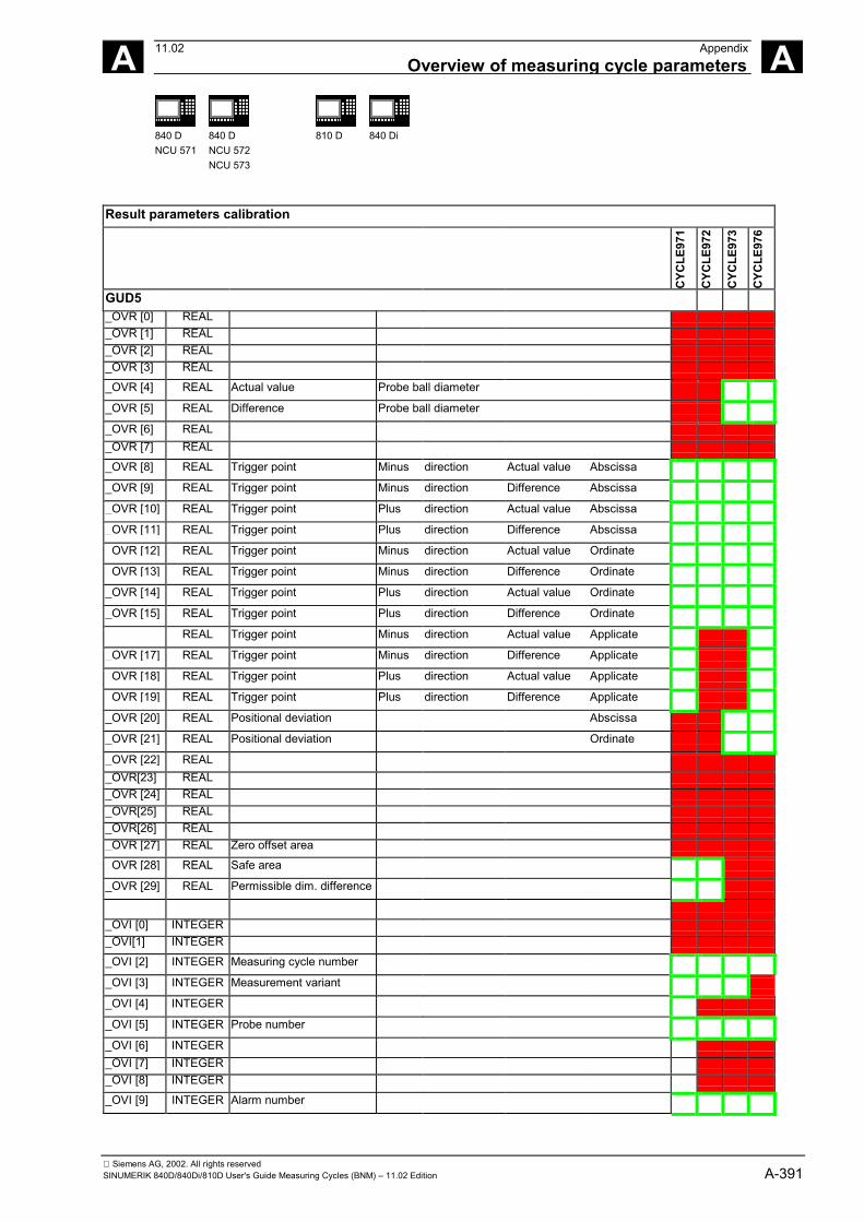
Siemens AG, 2002. All rights reservedSINUMERIK 840D/840Di/810D User's Guide Measuring Cycles (BNM) – 11.02 Edition A-391
A 11.02 AppendixOverview of measuring cycle parameters A
840 DNCU 571
840 DNCU 572NCU 573
810 D 840 Di
Result parameters calibration
CYC
LE97
1
CYC
LE97
2
CYC
LE97
3
CYC
LE97
6
GUD5_OVR [0] REAL_OVR [1] REAL_OVR [2] REAL_OVR [3] REAL
_OVR [4] REAL Actual value Probe ball diameter
_OVR [5] REAL Difference Probe ball diameter
_OVR [6] REAL_OVR [7] REAL
_OVR [8] REAL Trigger point Minus direction Actual value Abscissa
_OVR [9] REAL Trigger point Minus direction Difference Abscissa
_OVR [10] REAL Trigger point Plus direction Actual value Abscissa
_OVR [11] REAL Trigger point Plus direction Difference Abscissa
_OVR [12] REAL Trigger point Minus direction Actual value Ordinate
_OVR [13] REAL Trigger point Minus direction Difference Ordinate
_OVR [14] REAL Trigger point Plus direction Actual value Ordinate
_OVR [15] REAL Trigger point Plus direction Difference Ordinate
REAL Trigger point Minus direction Actual value Applicate
_OVR [17] REAL Trigger point Minus direction Difference Applicate
_OVR [18] REAL Trigger point Plus direction Actual value Applicate
_OVR [19] REAL Trigger point Plus direction Difference Applicate
_OVR [20] REAL Positional deviation Abscissa
_OVR [21] REAL Positional deviation Ordinate
_OVR [22] REAL_OVR[23] REAL_OVR [24] REAL_OVR[25] REAL_OVR[26] REAL_OVR [27] REAL Zero offset area
_OVR [28] REAL Safe area
_OVR [29] REAL Permissible dim. difference
_OVI [0] INTEGER_OVI[1] INTEGER
_OVI [2] INTEGER Measuring cycle number
_OVI [3] INTEGER Measurement variant
_OVI [4] INTEGER
_OVI [5] INTEGER Probe number
_OVI [6] INTEGER_OVI [7] INTEGER_OVI [8] INTEGER
_OVI [9] INTEGER Alarm number
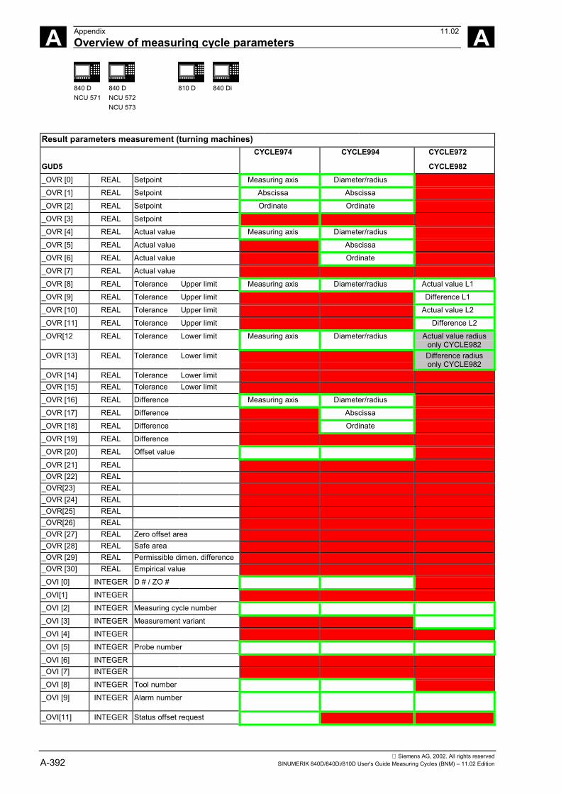
Siemens AG, 2002. All rights reservedA-392 SINUMERIK 840D/840Di/810D User's Guide Measuring Cycles (BNM) – 11.02 Edition
A Appendix 11.02Overview of measuring cycle parameters A
840 DNCU 571
840 DNCU 572NCU 573
810 D 840 Di
Result parameters measurement (turning machines)CYCLE974 CYCLE994 CYCLE972
GUD5 CYCLE982_OVR [0] REAL Setpoint Measuring axis Diameter/radius
_OVR [1] REAL Setpoint Abscissa Abscissa
_OVR [2] REAL Setpoint Ordinate Ordinate
_OVR [3] REAL Setpoint
_OVR [4] REAL Actual value Measuring axis Diameter/radius
_OVR [5] REAL Actual value Abscissa
_OVR [6] REAL Actual value Ordinate
_OVR [7] REAL Actual value
_OVR [8] REAL Tolerance Upper limit Measuring axis Diameter/radius Actual value L1
_OVR [9] REAL Tolerance Upper limit Difference L1
_OVR [10] REAL Tolerance Upper limit Actual value L2
_OVR [11] REAL Tolerance Upper limit Difference L2
_OVR[12 REAL Tolerance Lower limit Measuring axis Diameter/radius Actual value radiusonly CYCLE982
_OVR [13] REAL Tolerance Lower limit Difference radiusonly CYCLE982
_OVR [14] REAL Tolerance Lower limit_OVR [15] REAL Tolerance Lower limit
_OVR [16] REAL Difference Measuring axis Diameter/radius
_OVR [17] REAL Difference Abscissa
_OVR [18] REAL Difference Ordinate
_OVR [19] REAL Difference
_OVR [20] REAL Offset value
_OVR [21] REAL_OVR [22] REAL_OVR[23] REAL_OVR [24] REAL_OVR[25] REAL_OVR[26] REAL_OVR [27] REAL Zero offset area_OVR [28] REAL Safe area_OVR [29] REAL Permissible dimen. difference_OVR [30] REAL Empirical value
_OVI [0] INTEGER D # / ZO #
_OVI[1] INTEGER
_OVI [2] INTEGER Measuring cycle number
_OVI [3] INTEGER Measurement variant
_OVI [4] INTEGER
_OVI [5] INTEGER Probe number
_OVI [6] INTEGER_OVI [7] INTEGER
_OVI [8] INTEGER Tool number
_OVI [9] INTEGER Alarm number
_OVI[11] INTEGER Status offset request
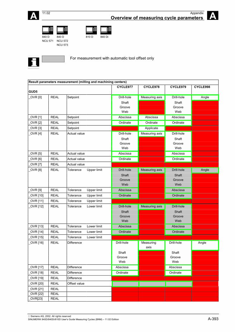
Siemens AG, 2002. All rights reservedSINUMERIK 840D/840Di/810D User's Guide Measuring Cycles (BNM) – 11.02 Edition A-393
A 11.02 AppendixOverview of measuring cycle parameters A
840 DNCU 571
840 DNCU 572NCU 573
810 D 840 Di
For measurement with automatic tool offset only
Result parameters measurement (milling and machining centers)CYCLE977 CYCLE978 CYCLE979 CYCLE998
GUD5_OVR [0] REAL Setpoint Drill-hole Measuring axis Drill-hole Angle
Shaft ShaftGroove Groove
Web Web
_OVR [1] REAL Setpoint Abscissa Abscissa Abscissa
_OVR [2] REAL Setpoint Ordinate Ordinate Ordinate
_OVR [3] REAL Setpoint Applicate
_OVR [4] REAL Actual value Drill-hole Measuring axis Drill-hole
Shaft ShaftGroove Groove
Web Web
_OVR [5] REAL Actual value Abscissa Abscissa
_OVR [6] REAL Actual value Ordinate Ordinate
_OVR [7] REAL Actual value
_OVR [8] REAL Tolerance Upper limit Drill-hole Measuring axis Drill-hole Angle
Shaft ShaftGroove Groove
Web Web
_OVR [9] REAL Tolerance Upper limit Abscissa Abscissa
_OVR [10] REAL Tolerance Upper limit Ordinate Ordinate
_OVR [11] REAL Tolerance Upper limit
_OVR [12] REAL Tolerance Lower limit Drill-hole Measuring axis Drill-hole
Shaft ShaftGroove Groove
Web Web
_OVR [13] REAL Tolerance Lower limit Abscissa Abscissa
_OVR [14] REAL Tolerance Lower limit Ordinate Ordinate
_OVR [15] REAL Tolerance Lower limit
_OVR [16] REAL Difference Drill-hole Measuringaxis
Drill-hole Angle
Shaft ShaftGroove Groove
Web Web
_OVR [17] REAL Difference Abscissa Abscissa
_OVR [18] REAL Difference Ordinate Ordinate
_OVR [19] REAL Difference
_OVR [20] REAL Offset value
_OVR [21] REAL_OVR [22] REAL_OVR[23] REAL
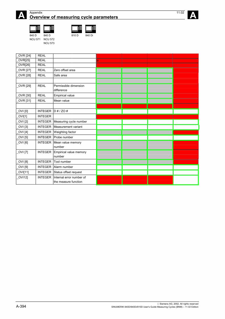
Siemens AG, 2002. All rights reservedA-394 SINUMERIK 840D/840Di/810D User's Guide Measuring Cycles (BNM) – 11.02 Edition
A Appendix 11.02Overview of measuring cycle parameters A
840 DNCU 571
840 DNCU 572NCU 573
810 D 840 Di
_OVR [24] REAL_OVR[25] REAL a_OVR[26] REAL
_OVR [27] REAL Zero offset area
_OVR [28] REAL Safe area
_OVR [29] REAL Permissible dimensiondifference
_OVR [30] REAL Empirical value
_OVR [31] REAL Mean value
_OVI [0] INTEGER D # / ZO #
_OVI[1] INTEGER
_OVI [2] INTEGER Measuring cycle number
_OVI [3] INTEGER Measurement variant
_OVI [4] INTEGER Weighting factor
_OVI [5] INTEGER Probe number
_OVI [6] INTEGER Mean value memorynumber
_OVI [7] INTEGER Empirical value memorynumber
_OVI [8] INTEGER Tool number
_OVI [9] INTEGER Alarm number
_OVI[11] INTEGER Status offset request
_OVI12] INTEGER Internal error number ofthe measure function
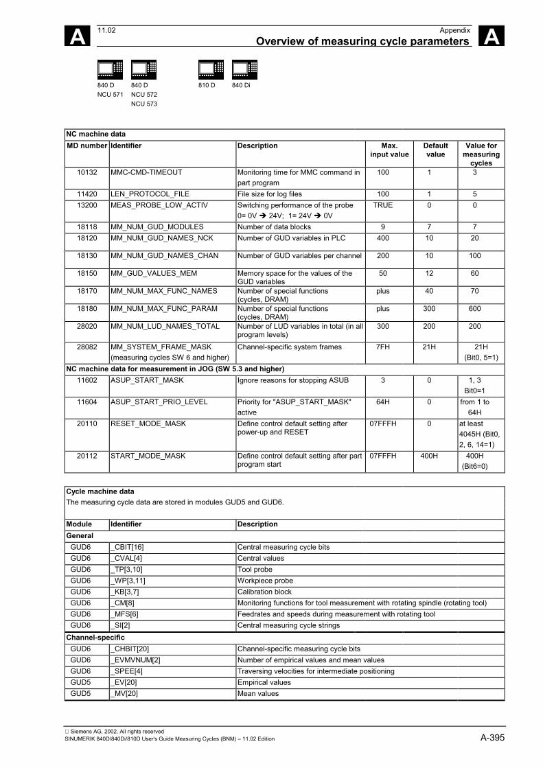
Siemens AG, 2002. All rights reservedSINUMERIK 840D/840Di/810D User's Guide Measuring Cycles (BNM) – 11.02 Edition A-395
A 11.02 AppendixOverview of measuring cycle parameters A
840 DNCU 571
840 DNCU 572NCU 573
810 D 840 Di
NC machine dataMD number Identifier Description Max.
input valueDefaultvalue
Value formeasuring
cycles10132 MMC-CMD-TIMEOUT Monitoring time for MMC command in
part program100 1 3
11420 LEN_PROTOCOL_FILE File size for log files 100 1 513200 MEAS_PROBE_LOW_ACTIV Switching performance of the probe
0= 0V � 24V; 1= 24V � 0VTRUE 0 0
18118 MM_NUM_GUD_MODULES Number of data blocks 9 7 718120 MM_NUM_GUD_NAMES_NCK Number of GUD variables in PLC 400 10 20
18130 MM_NUM_GUD_NAMES_CHAN Number of GUD variables per channel 200 10 100
18150 MM_GUD_VALUES_MEM Memory space for the values of theGUD variables
50 12 60
18170 MM_NUM_MAX_FUNC_NAMES Number of special functions(cycles, DRAM)
plus 40 70
18180 MM_NUM_MAX_FUNC_PARAM Number of special functions(cycles, DRAM)
plus 300 600
28020 MM_NUM_LUD_NAMES_TOTAL Number of LUD variables in total (in allprogram levels)
300 200 200
28082 MM_SYSTEM_FRAME_MASK(measuring cycles SW 6 and higher)
Channel-specific system frames 7FH 21H 21H(Bit0, 5=1)
NC machine data for measurement in JOG (SW 5.3 and higher)11602 ASUP_START_MASK Ignore reasons for stopping ASUB 3 0 1, 3
Bit0=111604 ASUP_START_PRIO_LEVEL Priority for "ASUP_START_MASK"
active64H 0 from 1 to
64H20110 RESET_MODE_MASK Define control default setting after
power-up and RESET07FFFH 0 at least
4045H (Bit0,2, 6, 14=1)
20112 START_MODE_MASK Define control default setting after partprogram start
07FFFH 400H 400H(Bit6=0)
Cycle machine dataThe measuring cycle data are stored in modules GUD5 and GUD6.
Module Identifier DescriptionGeneral
GUD6 _CBIT[16] Central measuring cycle bitsGUD6 _CVAL[4] Central valuesGUD6 _TP[3,10] Tool probeGUD6 _WP[3,11] Workpiece probeGUD6 _KB[3,7] Calibration blockGUD6 _CM[8] Monitoring functions for tool measurement with rotating spindle (rotating tool)GUD6 _MFS[6] Feedrates and speeds during measurement with rotating toolGUD6 _SI[2] Central measuring cycle strings
Channel-specificGUD6 _CHBIT[20] Channel-specific measuring cycle bitsGUD6 _EVMVNUM[2] Number of empirical values and mean valuesGUD6 _SPEE[4] Traversing velocities for intermediate positioningGUD5 _EV[20] Empirical valuesGUD5 _MV[20] Mean values
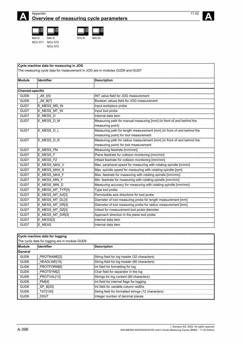
Siemens AG, 2002. All rights reservedA-396 SINUMERIK 840D/840Di/810D User's Guide Measuring Cycles (BNM) – 11.02 Edition
A Appendix 11.02Overview of measuring cycle parameters A
840 DNCU 571
840 DNCU 572NCU 573
810 D 840 Di
Cycle machine data for measuring in JOGThe measuring cycle data for measurement in JOG are in modules GUD6 and GUD7
Module Identifier Description
Channel-specificGUD6 _JM_I[5] INT value field for JOG measurementGUD6 _JM_B[7] Boolean values field for JOG measurementGUD7 E_MESS_MS_IN Input workpiece probeGUD7 E_MESS_MT_IN Input tool probeGUD7 E_MESS_D Internal data itemGUD7 E_MESS_D_M Measuring path for manual measuring [mm] (in front of and behind the
measuring point)GUD7 E_MESS_D_L Measuring path for length measurement [mm] (in front of and behind the
measuring point) for tool measurementGUD7 E_MESS_D_R Measuring path for radius measurement [mm] (in front of and behind the
measuring point) for tool measurementGUD7 E_MESS_FM Measuring feedrate [mm/min]GUD7 E_MESS_F Plane feedrate for collision monitoring [mm/min]GUD7 E_MESS_FZ Infeed feedrate for collision monitoring [mm/min]GUD7 E_MESS_MAX_V Max. peripheral speed for measuring with rotating spindle [m/min]GUD7 E_MESS_MAX_S Max. spindle speed for measuring with rotating spindle [rpm]GUD7 E_MESS_MAX_F Max. feedrate for measuring with rotating spindle [mm/min]GUD7 E_MESS_MIN_F Min. feedrate for measuring with rotating spindle [mm/min]GUD7 E_MESS_MIN_D Measuring accuracy for measuring with rotating spindle [mm/min]GUD7 E_MESS_MT_TYP[3] Type tool probeGUD7 E_MESS_MT_AX[3] Permissible axis directions for tool probeGUD7 E_MESS_MT_DL[3] Diameter of tool measuring probe for length measurement [mm]GUD7 E_MESS_MT_DR[3] Diameter of tool measuring probe for radius measurement [mm]GUD7 E_MESS_MT_DZ[3] Infeed for measurement tool probe diameterGUD7 E_MESS_MT_DIR[3] Approach direction in the plane tool probeGUD7 E_MESS[3] Internal data itemGUD7 E_MEAS Internal data item
Cycle machine data for loggingThe cycle data for logging are in module GUD6Module Identifier DescriptionGeneral
GUD6 _PROTNAME[2] String field for log header (32 characters)GUD6 _HEADLINE[10] String field for log header (80 characters)GUD6 _PROTFORM[6] Int field for formatting for logGUD6 _PROTSYM[2] Char field for separator in the logGUD6 _PROTVAL[13] Strings for log content (80 characters)GUD6 _PMI[4] Int field for internal flags for loggingGUD6 _SP_B[20] Int field for variable column widthsGUD6 _TXT[100] String field for formatted strings (12 characters)GUD6 _DIGIT Integer number of decimal places
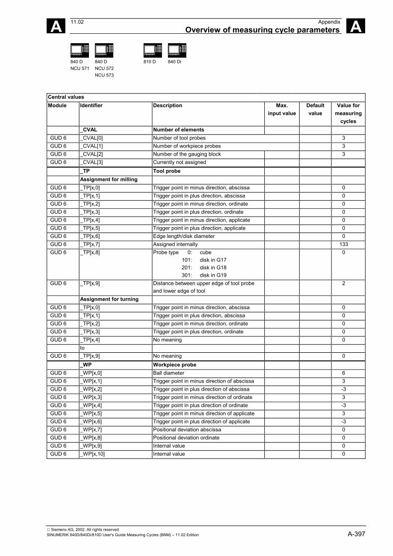
Siemens AG, 2002. All rights reservedSINUMERIK 840D/840Di/810D User's Guide Measuring Cycles (BNM) – 11.02 Edition A-397
A 11.02 AppendixOverview of measuring cycle parameters A
840 DNCU 571
840 DNCU 572NCU 573
810 D 840 Di
Central valuesModule Identifier Description Max.
input valueDefaultvalue
Value formeasuring
cycles_CVAL Number of elements
GUD 6 _CVAL[0] Number of tool probes 3GUD 6 _CVAL[1] Number of workpiece probes 3GUD 6 _CVAL[2] Number of the gauging block 3GUD 6 _CVAL[3] Currently not assigned
_TP Tool probeAssignment for milling
GUD 6 _TP[x,0] Trigger point in minus direction, abscissa 0GUD 6 _TP[x,1] Trigger point in plus direction, abscissa 0GUD 6 _TP[x,2] Trigger point in minus direction, ordinate 0GUD 6 _TP[x,3] Trigger point in plus direction, ordinate 0GUD 6 _TP[x,4] Trigger point in minus direction, applicate 0GUD 6 _TP[x,5] Trigger point in plus direction, applicate 0GUD 6 _TP[x,6] Edge length/disk diameter 0GUD 6 _TP[x,7] Assigned internally 133GUD 6 _TP[x,8] Probe type 0: cube
101: disk in G17201: disk in G18301: disk in G19
0
GUD 6 _TP[x,9] Distance between upper edge of tool probeand lower edge of tool
2
Assignment for turningGUD 6 _TP[x,0] Trigger point in minus direction, abscissa 0GUD 6 _TP[x,1] Trigger point in plus direction, abscissa 0GUD 6 _TP[x,2] Trigger point in minus direction, ordinate 0GUD 6 _TP[x,3] Trigger point in plus direction, ordinate 0GUD 6 _TP[x,4] No meaning 0
toGUD 6 _TP[x,9] No meaning 0
_WP Workpiece probeGUD 6 _WP[x,0] Ball diameter 6GUD 6 _WP[x,1] Trigger point in minus direction of abscissa 3GUD 6 _WP[x,2] Trigger point in plus direction of abscissa -3GUD 6 _WP[x,3] Trigger point in minus direction of ordinate 3GUD 6 _WP[x,4] Trigger point in plus direction of ordinate -3GUD 6 _WP[x,5] Trigger point in minus direction of applicate 3GUD 6 _WP[x,6] Trigger point in plus direction of applicate -3GUD 6 _WP[x,7] Positional deviation abscissa 0GUD 6 _WP[x,8] Positional deviation ordinate 0GUD 6 _WP[x,9] Internal value 0GUD 6 _WP[x,10] Internal value 0
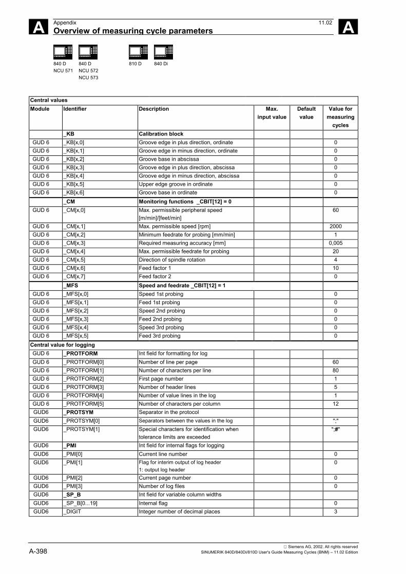
Siemens AG, 2002. All rights reservedA-398 SINUMERIK 840D/840Di/810D User's Guide Measuring Cycles (BNM) – 11.02 Edition
A Appendix 11.02Overview of measuring cycle parameters A
840 DNCU 571
840 DNCU 572NCU 573
810 D 840 Di
Central valuesModule Identifier Description Max.
input valueDefaultvalue
Value formeasuring
cycles_KB Calibration block
GUD 6 _KB[x,0] Groove edge in plus direction, ordinate 0GUD 6 _KB[x,1] Groove edge in minus direction, ordinate 0GUD 6 _KB[x,2] Groove base in abscissa 0GUD 6 _KB[x,3] Groove edge in plus direction, abscissa 0GUD 6 _KB[x,4] Groove edge in minus direction, abscissa 0GUD 6 _KB[x,5] Upper edge groove in ordinate 0GUD 6 _KB[x,6] Groove base in ordinate 0
_CM Monitoring functions _CBIT[12] = 0GUD 6 _CM[x,0] Max. permissible peripheral speed
[m/min]/[feet/min]60
GUD 6 _CM[x,1] Max. permissible speed [rpm] 2000GUD 6 _CM[x,2] Minimum feedrate for probing [mm/min] 1GUD 6 _CM[x,3] Required measuring accuracy [mm] 0,005GUD 6 _CM[x,4] Max. permissible feedrate for probing 20GUD 6 _CM[x,5] Direction of spindle rotation 4GUD 6 _CM[x,6] Feed factor 1 10GUD 6 _CM[x,7] Feed factor 2 0
_MFS Speed and feedrate _CBIT[12] = 1GUD 6 _MFS[x,0] Speed 1st probing 0GUD 6 _MFS[x,1] Feed 1st probing 0GUD 6 _MFS[x,2] Speed 2nd probing 0GUD 6 _MFS[x,3] Feed 2nd probing 0GUD 6 _MFS[x,4] Speed 3rd probing 0GUD 6 _MFS[x,5] Feed 3rd probing 0
Central value for loggingGUD 6 _PROTFORM Int field for formatting for logGUD 6 _PROTFORM[0] Number of line per page 60GUD 6 _PROTFORM[1] Number of characters per line 80GUD 6 _PROTFORM[2] First page number 1GUD 6 _PROTFORM[3] Number of header lines 5GUD 6 _PROTFORM[4] Number of value lines in the log 1GUD 6 _PROTFORM[5] Number of characters per column 12GUD6 _PROTSYM Separator in the protocolGUD6 _PROTSYM[0] Separators between the values in the log ";"GUD6 _PROTSYM[1] Special characters for identification when
tolerance limits are exceeded";#"
GUD6 _PMI Int field for internal flags for loggingGUD6 _PMI[0] Current line number 0GUD6 _PMI[1] Flag for interim output of log header
1: output log header0
GUD6 _PMI[2] Current page number 0GUD6 _PMI[3] Number of log files 0GUD6 _SP_B Int field for variable column widthsGUD6 _SP_B[0...19] Internal flag 0GUD6 _DIGIT Integer number of decimal places 3
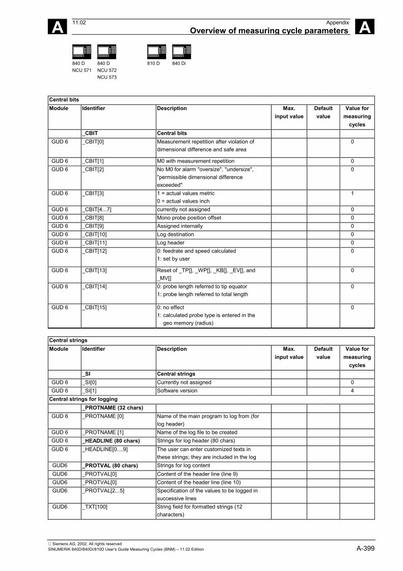
Siemens AG, 2002. All rights reservedSINUMERIK 840D/840Di/810D User's Guide Measuring Cycles (BNM) – 11.02 Edition A-399
A 11.02 AppendixOverview of measuring cycle parameters A
840 DNCU 571
840 DNCU 572NCU 573
810 D 840 Di
Central bitsModule Identifier Description Max.
input valueDefaultvalue
Value formeasuring
cycles_CBIT Central bits
GUD 6 _CBIT[0] Measurement repetition after violation ofdimensional difference and safe area
0
GUD 6 _CBIT[1] M0 with measurement repetition 0GUD 6 _CBIT[2] No M0 for alarm "oversize", "undersize",
"permissible dimensional differenceexceeded"
0
GUD 6 _CBIT[3] 1 = actual values metric0 = actual values inch
1
GUD 6 _CBIT[4...7] currently not assigned 0GUD 6 _CBIT[8] Mono probe position offset 0GUD 6 _CBIT[9] Assigned internally 0GUD 6 _CBIT[10] Log destination 0GUD 6 _CBIT[11] Log header 0GUD 6 _CBIT[12] 0: feedrate and speed calculated
1: set by user0
GUD 6 _CBIT[13] Reset of _TP[], _WP[], _KB[], _EV[], and_MV[]
0
GUD 6 _CBIT[14] 0: probe length referred to tip equator1: probe length referred to total length
0
GUD 6 _CBIT[15] 0: no effect1: calculated probe type is entered in the geo memory (radius)
0
Central stringsModule Identifier Description Max.
input valueDefaultvalue
Value formeasuring
cycles_SI Central strings
GUD 6 _SI[0] Currently not assigned 0GUD 6 _SI[1] Software version 4
Central strings for logging_PROTNAME (32 chars)
GUD 6 _PROTNAME [0] Name of the main program to log from (forlog header)
GUD 6 _PROTNAME [1] Name of the log file to be createdGUD 6 _HEADLINE (80 chars) Strings for log header (80 chars)GUD 6 _HEADLINE[0....9] The user can enter customized texts in
these strings; they are included in the logGUD6 _PROTVAL (80 chars) Strings for log contentGUD6 _PROTVAL[0] Content of the header line (line 9)GUD6 _PROTVAL[0] Content of the header line (line 10)GUD6 _PROTVAL[2...5] Specification of the values to be logged in
successive linesGUD6 _TXT[100] String field for formatted strings (12
characters)
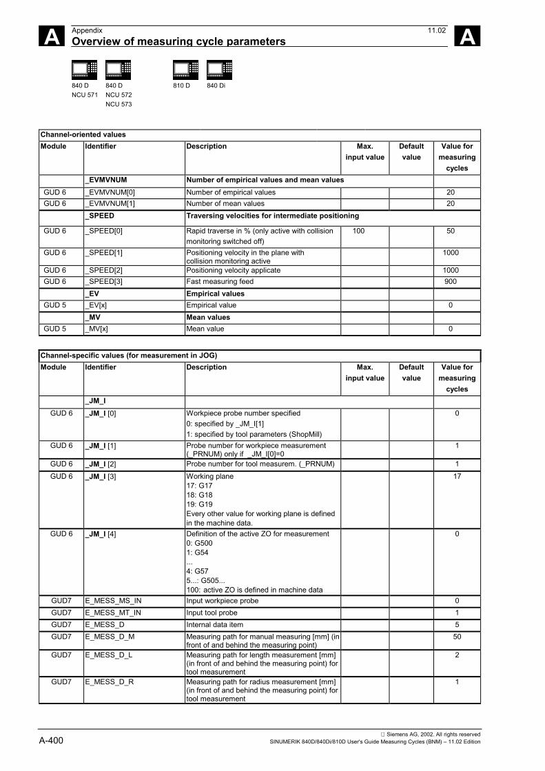
Siemens AG, 2002. All rights reservedA-400 SINUMERIK 840D/840Di/810D User's Guide Measuring Cycles (BNM) – 11.02 Edition
A Appendix 11.02Overview of measuring cycle parameters A
840 DNCU 571
840 DNCU 572NCU 573
810 D 840 Di
Channel-oriented valuesModule Identifier Description Max.
input valueDefaultvalue
Value formeasuring
cycles_EVMVNUM Number of empirical values and mean values
GUD 6 _EVMVNUM[0] Number of empirical values 20GUD 6 _EVMVNUM[1] Number of mean values 20
_SPEED Traversing velocities for intermediate positioning
GUD 6 _SPEED[0] Rapid traverse in % (only active with collisionmonitoring switched off)
100 50
GUD 6 _SPEED[1] Positioning velocity in the plane withcollision monitoring active
1000
GUD 6 _SPEED[2] Positioning velocity applicate 1000GUD 6 _SPEED[3] Fast measuring feed 900
_EV Empirical valuesGUD 5 _EV[x] Empirical value 0
_MV Mean valuesGUD 5 _MV[x] Mean value 0
Channel-specific values (for measurement in JOG)Module Identifier Description Max.
input valueDefaultvalue
Value formeasuring
cycles_JM_I
GUD 6 _JM_I [0] Workpiece probe number specified0: specified by _JM_I[1]1: specified by tool parameters (ShopMill)
0
GUD 6 _JM_I [1] Probe number for workpiece measurement(_PRNUM) only if _JM_I[0]=0
1
GUD 6 _JM_I [2] Probe number for tool measurem. (_PRNUM) 1GUD 6 _JM_I [3] Working plane
17: G1718: G1819: G19Every other value for working plane is definedin the machine data.
17
GUD 6 _JM_I [4] Definition of the active ZO for measurement0: G5001: G54...4: G575...: G505...100: active ZO is defined in machine data
0
GUD7 E_MESS_MS_IN Input workpiece probe 0GUD7 E_MESS_MT_IN Input tool probe 1GUD7 E_MESS_D Internal data item 5GUD7 E_MESS_D_M Measuring path for manual measuring [mm] (in
front of and behind the measuring point)50
GUD7 E_MESS_D_L Measuring path for length measurement [mm](in front of and behind the measuring point) fortool measurement
2
GUD7 E_MESS_D_R Measuring path for radius measurement [mm](in front of and behind the measuring point) fortool measurement
1
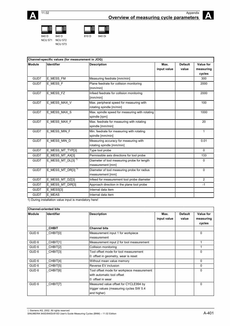
Siemens AG, 2002. All rights reservedSINUMERIK 840D/840Di/810D User's Guide Measuring Cycles (BNM) – 11.02 Edition A-401
A 11.02 AppendixOverview of measuring cycle parameters A
840 DNCU 571
840 DNCU 572NCU 573
810 D 840 Di
Channel-specific values (for measurement in JOG)Module Identifier Description Max.
input valueDefaultvalue
Value formeasuring
cyclesGUD7 E_MESS_FM Measuring feedrate [mm/min] 300GUD7 E_MESS_F Plane feedrate for collision monitoring
[mm/min]2000
GUD7 E_MESS_FZ Infeed feedrate for collision monitoring[mm/min]
2000
GUD7 E_MESS_MAX_V Max. peripheral speed for measuring withrotating spindle [m/min]
100
GUD7 E_MESS_MAX_S Max. spindle speed for measuring with rotatingspindle [rpm]
1000
GUD7 E_MESS_MAX_F Max. feedrate for measuring with rotatingspindle [mm/min]
20
GUD7 E_MESS_MIN_F Min. feedrate for measuring with rotatingspindle [mm/min]
1
GUD7 E_MESS_MIN_D Measuring accuracy for measuring withrotating spindle [mm/min]
0.01
GUD7 E_MESS_MT_TYP[3] Type tool probe 0GUD7 E_MESS_MT_AX[3] Permissible axis directions for tool probe 133GUD7 E_MESS_MT_DL[3] 1) Diameter of tool measuring probe for length
measurement [mm]0
GUD7 E_MESS_MT_DR[3] 1) Diameter of tool measuring probe for radiusmeasurement [mm]
0
GUD7 E_MESS_MT_DZ[3] Infeed for measurement tool probe diameter 2GUD7 E_MESS_MT_DIR[3] Approach direction in the plane tool probe -1GUD7 E_MESS[3] Internal data itemGUD7 E_MEAS Internal data item
1) During installation value input is mandatory here!
Channel-oriented bitsModule Identifier Description Max.
input valueDefaultvalue
Value formeasuring
cycles_CHBIT Channel bits
GUD 6 _CHBIT[0] Measurement input 1 for workpiecemeasurement
0
GUD 6 _CHBIT[1] Measurement input 2 for tool measurement 1GUD 6 _CHBIT[2] Collision monitoring 1GUD 6 _CHBIT[3] Tool offset mode for tool measurement
0: offset in geometry, wear is reset0
GUD 6 _CHBIT[4] Without mean value memory 0GUD 6 _CHBIT[5] Reverse EV inclusion 0GUD 6 _CHBIT[6] Tool offset mode for workpiece measurement
with automatic tool offset0: offset in wear
0
GUD 6 _CHBIT[7] Measured value offset for CYCLE994 bytrigger values (measuring cycles SW 5.4and higher)
0
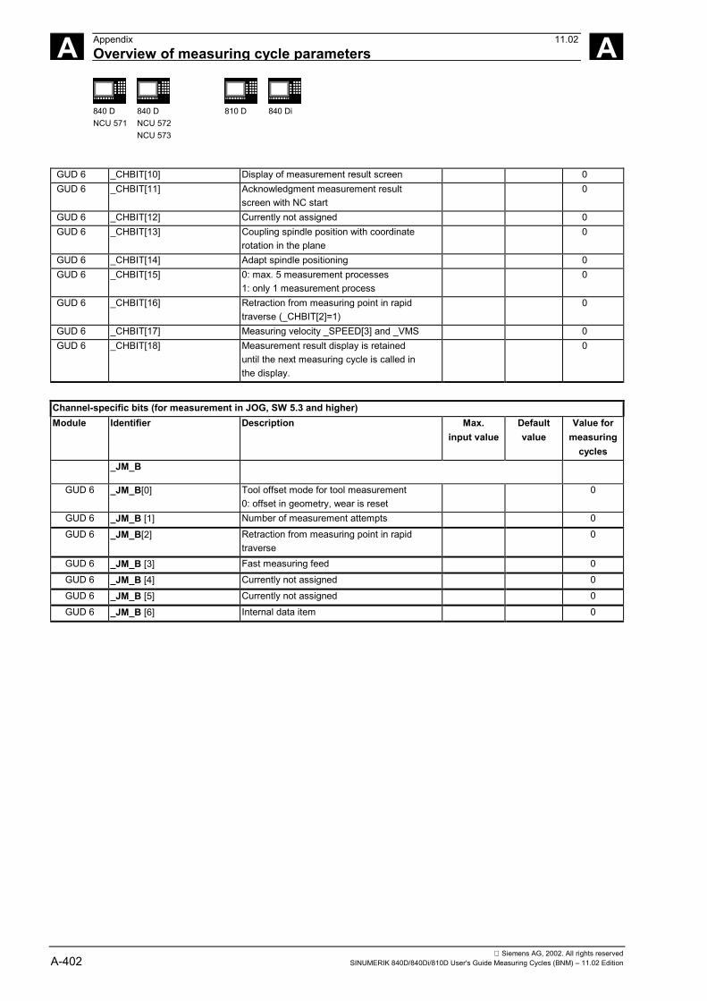
Siemens AG, 2002. All rights reservedA-402 SINUMERIK 840D/840Di/810D User's Guide Measuring Cycles (BNM) – 11.02 Edition
A Appendix 11.02Overview of measuring cycle parameters A
840 DNCU 571
840 DNCU 572NCU 573
810 D 840 Di
GUD 6 _CHBIT[10] Display of measurement result screen 0GUD 6 _CHBIT[11] Acknowledgment measurement result
screen with NC start0
GUD 6 _CHBIT[12] Currently not assigned 0GUD 6 _CHBIT[13] Coupling spindle position with coordinate
rotation in the plane0
GUD 6 _CHBIT[14] Adapt spindle positioning 0GUD 6 _CHBIT[15] 0: max. 5 measurement processes
1: only 1 measurement process0
GUD 6 _CHBIT[16] Retraction from measuring point in rapidtraverse (_CHBIT[2]=1)
0
GUD 6 _CHBIT[17] Measuring velocity _SPEED[3] and _VMS 0GUD 6 _CHBIT[18] Measurement result display is retained
until the next measuring cycle is called inthe display.
0
Channel-specific bits (for measurement in JOG, SW 5.3 and higher)Module Identifier Description Max.
input valueDefaultvalue
Value formeasuring
cycles_JM_B
GUD 6 _JM_B[0] Tool offset mode for tool measurement0: offset in geometry, wear is reset
0
GUD 6 _JM_B [1] Number of measurement attempts 0GUD 6 _JM_B[2] Retraction from measuring point in rapid
traverse0
GUD 6 _JM_B [3] Fast measuring feed 0GUD 6 _JM_B [4] Currently not assigned 0GUD 6 _JM_B [5] Currently not assigned 0GUD 6 _JM_B [6] Internal data item 0
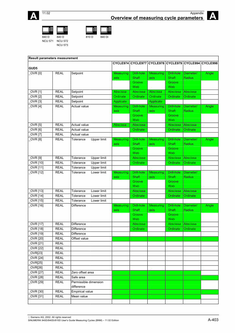
Siemens AG, 2002. All rights reservedSINUMERIK 840D/840Di/810D User's Guide Measuring Cycles (BNM) – 11.02 Edition A-403
A 11.02 AppendixOverview of measuring cycle parameters A
840 DNCU 571
840 DNCU 572NCU 573
810 D 840 Di
Result parameters measurementCYCLE974 CYCLE977 CYCLE978 CYCLE979 CYCLE994 CYCLE998
GUD5_OVR [0] REAL Setpoint Measuring
axisDrill-holeShaft
Measuringaxis
Drill-holeShaft
Diameter/Radius
Angle
Groove GrooveWeb Web
_OVR [1] REAL Setpoint Abscissa Abscissa Abscissa Abscissa Abscissa_OVR [2] REAL Setpoint Ordinate Ordinate Ordinate Ordinate Ordinate_OVR [3] REAL Setpoint Applicate Applicate_OVR [4] REAL Actual value Measuring
axisDrill-holeShaft
Measuringaxis
Drill-holeShaft
Diameter/Radius
Angle
Groove GrooveWeb Web
_OVR [5] REAL Actual value Abscissa Abscissa Abscissa Abscissa_OVR [6] REAL Actual value Ordinate Ordinate Ordinate_OVR [7] REAL Actual value_OVR [8] REAL Tolerance Upper limit Measuring
axisDrill-holeShaft
Measuringaxis
Drill-holeShaft
Diameter/Radius
Angle
Groove GrooveWeb Web
_OVR [9] REAL Tolerance Upper limit Abscissa Abscissa Abscissa_OVR [10] REAL Tolerance Upper limit Ordinate Ordinate Ordinate_OVR [11] REAL Tolerance Upper limit_OVR [12] REAL Tolerance Lower limit Measuring
axisDrill-holeShaft
Measuringaxis
Drill-holeShaft
Diameter/Radius
Groove GrooveWeb Web
_OVR [13] REAL Tolerance Lower limit Abscissa Abscissa Abscissa_OVR [14] REAL Tolerance Lower limit Ordinate Ordinate Ordinate_OVR [15] REAL Tolerance Lower limit_OVR [16] REAL Difference Measuring
axisDrill-holeShaft
Measuringaxis
Drill-holeShaft
Diameter/Radius
Angle
Groove GrooveWeb Web
_OVR [17] REAL Difference Abscissa Abscissa Abscissa_OVR [18] REAL Difference Ordinate Ordinate Ordinate_OVR [19] REAL Difference_OVR [20] REAL Offset value_OVR [21] REAL_OVR [22] REAL_OVR[23] REAL_OVR [24] REAL_OVR[25] REAL_OVR[26] REAL_OVR [27] REAL Zero offset area_OVR [28] REAL Safe area_OVR [29] REAL Permissible dimension
difference_OVR [30] REAL Empirical value_OVR [31] REAL Mean value
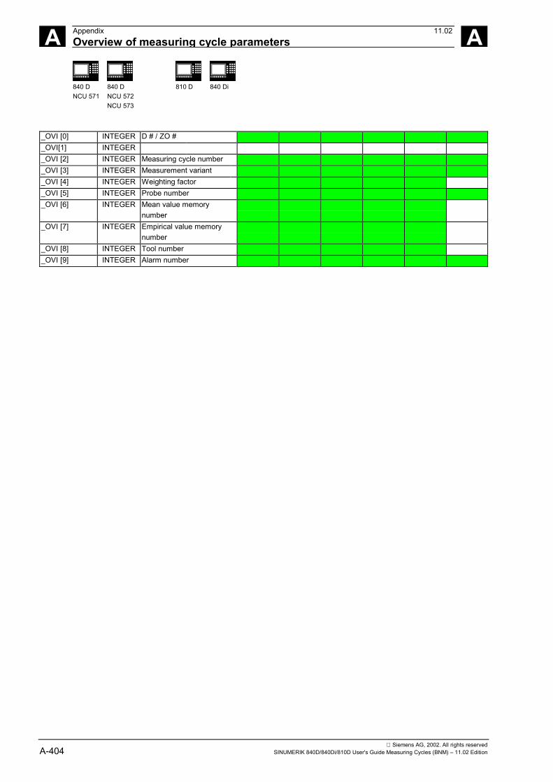
Siemens AG, 2002. All rights reservedA-404 SINUMERIK 840D/840Di/810D User's Guide Measuring Cycles (BNM) – 11.02 Edition
A Appendix 11.02Overview of measuring cycle parameters A
840 DNCU 571
840 DNCU 572NCU 573
810 D 840 Di
_OVI [0] INTEGER D # / ZO #_OVI[1] INTEGER_OVI [2] INTEGER Measuring cycle number_OVI [3] INTEGER Measurement variant_OVI [4] INTEGER Weighting factor_OVI [5] INTEGER Probe number_OVI [6] INTEGER Mean value memory
number_OVI [7] INTEGER Empirical value memory
number_OVI [8] INTEGER Tool number_OVI [9] INTEGER Alarm number
Siemens AG, 2002. All rights reservedSINUMERIK 840D/840Di/810D User's Guide Measuring Cycles (BNM) – 11.02 Edition A-405
A 11.02 AppendixAbbreviations A
840 DNCU 571
840 DNCU 572NCU 573
810 D 840 Di
B Abbreviations
CNC Computerized Numerical Control
CPU Central Processing Unit
DIN Deutsche Industrie Norm (German standard)
DOS Disk Operating System
DRF Differential Resolver Function
FM-NC Function Module - Numerical Control
GUD Global User Data
I/O Input/output
LUD Local User Data
MCS Machine Coordinate System
MD Machine Data
MMC Man-Machine Communication: User interface for NC for operating,programming, and simulation
MS Microsoft (software manufacturer)
NC Numerical Control
NCK Numerical Control Kernel: NC kernel with block preparation,traversing range, etc.
NCU Numerical Control Unit: Hardware unit of the NCK
PCIN Name of the software for data exchange with the control
PG Programming device
PLC Programmable Logic Control
Siemens AG, 2002. All rights reservedA-406 SINUMERIK 840D/840Di/810D User's Guide Measuring Cycles (BNM) – 11.02 Edition
A Appendix 11.02Abbreviations A
840 DNCU 571
840 DNCU 572NCU 573
810 D 840 Di
SR Subroutine
SW Software (version)
TO Tool Offset
TOA Tool Offset Active: Identification (file type) for tool offsets
UI User Interface
RS-232-C (V.24) Serial interface (defines exchange line between DTE and DCE)
WCS Workpiece Coordinate System
ZO Zero offset
Siemens AG, 2002. All rights reservedSINUMERIK 840D/840Di/810D User's Guide Measuring Cycles (BNM) – 11.02 Edition A-407
A 11.02 AppendixTerms A
840 DNCU 571
840 DNCU 572NCU 573
810 D 840 Di
C Terms
Important terms are listed below in alphabetical order. Cross-referencesto other entries in this glossary are indicated by the symbol ->.
A
Applicable probe types In order to measure tool and workpiece dimensions, a touch-triggerprobe is required that supplies a constant signal (rather than a pulse)when deflected.The probe type is defined in the measuring cycles in a parameter.Probes are therefore classified in three groups according to the numberof directions in which they can be deflected.• Multidirectional• Bidirectional• Monodirectional
B
Blank measurement The blank measurement ascertains the position, deviation, and zerooffset of the workpiece in the result of a -> workpiece measurement.
C
Calibration During calibration, the trigger points of the probe are ascertained andstored in the measuring cycles data in the GUD6 module.
Calibration tool Is a special tool (usually a cylindrical stylus), whose dimensions areknown and that is used for precisely determining the distances betweenthe machine zero and the probe trigger point (of the workpiece probe).
Collision monitoring In the context of measuring cycles, this is a function that monitors allintermediate positions generated within the measuring cycle for theswitching signal of the probe. When the probe switches, motion isstopped immediately and an alarm message is output.
Siemens AG, 2002. All rights reservedA-408 SINUMERIK 840D/840Di/810D User's Guide Measuring Cycles (BNM) – 11.02 Edition
A Appendix 11.02Terms A
840 DNCU 571
840 DNCU 572NCU 573
810 D 840 Di
DData modules formeasuring cycles
Data modules GUD5.DEF and GUD6.DEF contain data required forconfiguration and execution of the measuring cycles.These blocks must be loaded into the control during start-up. They mustthen be adapted according to the characteristics of the relevantmachine by the machine manufacturer.They are stored in the nonvolatile storage area of the control such thattheir setting values remain stored even when the control is switched offand on.
Delete distance-to-go If a measuring point is to be approached, a traverse command istransmitted to the position control loop and the probe is moved towardsthe measuring point. A point behind the expected measuring point isdefined as setpoint position. As soon as the probe makes contact, theactual axis value at the time the switching position is reached ismeasured and the drive is stopped. The remaining "distance-to-go" isdeleted.
Differentialmeasurement
Differential measurement means that the measuring point is measuredtwice, the first time at the probe position reached and the second timewith a spindle reversal of 180° (rotation of probe through 180°).
Dimension differencecheck
Is a tolerance window. On reaching a limit (_TDIF) the tool will probablybe worn and have to be replaced. The dimension difference check hasno effect on generation of the compensation value.
Display of measuringresults
Measuring results can be displayed automatically while a measuringcycle is running.Activation of this function depends on the configuration of themeasuring cycle interface in the MMC and the settings in the measuringcycle data.
E
Empirical value The empirical values are used to suppress constant dimensionaldeviations that are not subject to a trend.
Siemens AG, 2002. All rights reservedSINUMERIK 840D/840Di/810D User's Guide Measuring Cycles (BNM) – 11.02 Edition A-409
A 11.02 AppendixTerms A
840 DNCU 571
840 DNCU 572NCU 573
810 D 840 Di
G...J
Inprocessmeasurement
This method processes the probe signal directly in the NC.
K
L
Logging ofmeasurement results
Measurement results can be optionally be logged in a file located in thepart program memory as from SW4. The log can be output from thecontrol either via RS-232-C or on a diskette.
Lower tolerance limit When measuring a dimensional deviation as the lower tolerance limit(_TLL) ranging between "2/3 tolerance of workpiece" and "Dimensionaldifference control", this is regarded 100% as tool compensation. Theprevious average value is erased.AUTOMATIC operation is interrupted when the tolerance limit of theworkpiece is exceeded. "Undersize" is displayed to the operator depending on the tolerancezone position. Machining can be continued by means of NC start.
M
Mean value The mean value calculation takes account of the trend of thedimensional deviations of a machining series.The weighting factor k from which the mean value is derived isselectable.Mean value calculation alone is not enough to ensure constantmachining quality. The measured dimensional deviation can becorrected for constant deviations without a trend by an -> empiricalvalue.
Measure tool To perform tool measurement, the changed tool is moved up to theprobe which is either permanently fixed or swiveled into the workingrange. The automatically derived tool geometry is entered in therelevant tool offset data record.
Siemens AG, 2002. All rights reservedA-410 SINUMERIK 840D/840Di/810D User's Guide Measuring Cycles (BNM) – 11.02 Edition
A Appendix 11.02Terms A
840 DNCU 571
840 DNCU 572NCU 573
810 D 840 Di
Measurement accuracy The measurement accuracy which can be obtained is thusdependent on the following factors:• Repeat accuracy of the machine• Repeat accuracy of the probe• Resolution of the measuring systemThe repeat accuracy of the 840D and FM-NC controls for "on-the-flymeasurement" is ±1 µm.
Measurement at anyangle
A measurement variant used to measure a drill-hole, shaft, groove, orweb at random angles. The measurement path is traveled at a certainset angle.
Measurement pathmultiplication
The path increment a is normally 1 mm, but can be increased withparameter _FA when measuring cycles are called. -> Measuring pathmultiplication factor
Measurement variant The measurement variant of each measuring cycle is defined inparameter _MVAR.The parameter can have certain integer values for each measuringcycle, which are checked for validity within the cycle.
Measuring pathmultiplication factor
This parameter (_FA) is used to change the path increment a, which isnormally 1 mm, when the measuring cycles are called.
Measuring velocity The measuring speed can be freely selected by means of parameter_VMS.The maximum measuring speed must be selected such that safedeceleration within the probe deflecting path is ensured.
Monodirectional probe This type can only be used for workpiece measurement on millingmachines and machining centers with slight limitations.
Multidirectional probe With this type, measuring cycles for workpiece measurement can beused without limitation.
Multiple measurementat the same location
Parameter _NMSP can be used to determine the number ofmeasurements at the same location.The setpoint/actual value difference D is determined arithmetically.
Siemens AG, 2002. All rights reservedSINUMERIK 840D/840Di/810D User's Guide Measuring Cycles (BNM) – 11.02 Edition A-411
A 11.02 AppendixTerms A
840 DNCU 571
840 DNCU 572NCU 573
810 D 840 Di
N
O
Offset angle position If a -> monoprobe is used, the position of the probe can also becorrected for machine-specific reasons using the parameter _CORA.
P
Paraxial measurement A measurement variant used for paraxial measurement of aworkpieces, such as a drill-hole, shaft, rectangle, etc. The measuringpath is traveled paraxially.
Positional deviation The positional deviation describes the difference between the spindlecenter and the probe tip center ascertained by calibration. It iscompensated for by the measuring cycles.
Probe ball diameter The diameter of the probe tip. It is ascertained during calibration andstored in the measuring cycle data.
Probe type In order to measure tool and workpiece dimensions, a touch-triggerprobe is required that supplies a constant signal (rather than a pulse)when deflected.Probes are therefore classified in three groups according to the numberof directions in which they can be deflected.• Multidirectional• Bidirectional• Monodirectional
Q
R
Reference groove A groove located in the working area (permanent feature of themachine) whose precise position is known and that can be used tocalibrate workpiece probes.
Siemens AG, 2002. All rights reservedA-412 SINUMERIK 840D/840Di/810D User's Guide Measuring Cycles (BNM) – 11.02 Edition
A Appendix 11.02Terms A
840 DNCU 571
840 DNCU 572NCU 573
810 D 840 Di
S
Safe area The safe area _TSA does not affect the offset value; it is used fordiagnosis.If this limit is reached, there is a defect in the probe or the set position isincorrect.
Setpoint In the measuring procedure "inprocess measurement", a position isspecified as the -> setpoint value for the cycle at which the signal of thetouch-trigger probe is expected.
T
Tool name If tool management is active, the name of the tool can be entered inparameter _TNAME as an alternative to the -> tool number.The tool number is derived from it within the cycle and entered in_TNUM.
Tool number The parameter _TNUM contains the tool number of the tool to beautomatically offset after workpiece measurement.
Trigger point The trigger points of the probe are ascertained during calibration andstored in the GUD6 module for the axis direction.
U
Upper tolerance limit When measuring a dimensional deviation as the upper tolerance limit(_TUL) ranging between "2/3 tolerance of workpiece" and "Dimensionaldifference control", this is regarded 100% as tool compensation. Theprevious average value is erased.AUTOMATIC operation is interrupted when the tolerance limit of theworkpiece is exceeded. "Oversize" is displayed to the operator depending on the tolerance zoneposition. Machining can be continued by means of NC start.
V
Variable measuringvelocity
The measuring speed can be freely selected by means of _VMS.The maximum measuring speed must be selected such that safedeceleration within the probe deflecting path is ensured. ->Measuring velocity
Siemens AG, 2002. All rights reservedSINUMERIK 840D/840Di/810D User's Guide Measuring Cycles (BNM) – 11.02 Edition A-413
A 11.02 AppendixTerms A
840 DNCU 571
840 DNCU 572NCU 573
810 D 840 Di
W
Weighting factor formean value derivation
The weighting factor k can be applied to allow different weighting to begiven to an individual measurement.A new measurement result thus has only a limited effect on the new tooloffset as a function of _K.
Workpiecemeasurement
For workpiece measurement, a measuring probe is moved up to theclamped workpiece in the same way as a tool. The flexibility of themeasuring cycles makes it possible to perform nearly all measurementswhich may need to be taken on a milling machine.
X
Y
Z
Zero offset area This tolerance range (lower limit _TZL) corresponds to the amount ofmaximum accidental dimensional deviations. It has to be determined foreach machine.
ZO calculation In the result of a measurement, the actual-setpoint value difference isstored in the data set of any settable zero offset.

Siemens AG, 2002. All rights reservedA-414 SINUMERIK 840D/840Di/810D User's Guide Measuring Cycles (BNM) – 11.02 Edition
A Appendix 11.02Terms A
840 DNCU 571
840 DNCU 572NCU 573
810 D 840 Di
Notes
Siemens AG, 2002. All rights reservedSINUMERIK 840D/840Di/810D User's Guide Measuring Cycles (BNM) – 11.02 Edition A-415
A 11.02 AppendixReferences A
840 DNCU 571
840 DNCU 572NCU 573
810 D 840 Di
D References
General Documentation
/BU/ SINUMERIK 840D/840Di/810D/802S, C, DOrdering InformationCatalog NC 60Order No.: E86060-K4460-A101-A9-7600
/ST7/ SIMATICSIMATIC S7 Programmable Logic ControllersCatalog ST 70Order No.: E86060-K4670-A111-A3
/Z/ SINUMERIK, SIROTEC, SIMODRIVEAccessories and Equipment for Special-Purpose MachinesCatalog NC ZOrder No.: E86060-K4490-A001-A8-7600
Electronic Documentation
/CD1/ The SINUMERIK System (11.02 Edition)DOC ON CD(includes all SINUMERIK 840D/840Di/810D/802 and SIMODRIVEpublications)Order No.: 6FC5 298-6CA00-0BG3
Siemens AG, 2002. All rights reservedA-416 SINUMERIK 840D/840Di/810D User's Guide Measuring Cycles (BNM) – 11.02 Edition
A Appendix 11.02References A
840 DNCU 571
840 DNCU 572NCU 573
810 D 840 Di
/AUK/ SINUMERIK 840D/810DAutoTurn Short Operating Guide (09.01 Edition)Order No.: 6FC5 298-4AA30-0BP3
/AUP/ SINUMERIK 840D/810DAutoTurn Graphic Programming System (02.02 Edition)Operator's GuideProgramming/SetupOrder No.: 6FC5 298-4AA40-0BP3
/BA/ SINUMERIK 840D/810DOperator's Guide MMC (10.00 Edition)Order No.: 6FC5 298-6AA00-0BP0
/BAD/ SINUMERIK 840D/840Di/810DOperator's Guide HMI Advanced (11.02 Edition)Order No.: 6FC5 298-6AF00-0BP2
/BEM/ SINUMERIK 840D/810DOperator's Guide HMI Embedded (11.02 Edition)Order No.: 6FC5 298-6AC00-0BP2
/BAH/ SINUMERIK 840D/840Di/810DOperator's Guide HT 6 (06.02 Edition)Order No.: 6FC5 298-0AD60-0BP2
/BAK/ SINUMERIK 840D/840Di/810DShort Operating Guide (02.01 Edition)Order No.: 6FC5 298-6AA10-0BP0
/BAM/ SINUMERIK 810D/840DOperator's Guide ManualTurn (08.02 Edition)Order No.: 6FC5 298-6AD00-0BP0
User Documentation
Siemens AG, 2002. All rights reservedSINUMERIK 840D/840Di/810D User's Guide Measuring Cycles (BNM) – 11.02 Edition A-417
A 11.02 AppendixReferences A
840 DNCU 571
840 DNCU 572NCU 573
810 D 840 Di
/BAS/ SINUMERIK 840D/810DOperator's Guide ShopMill (09.02 Edition)Order No.: 6FC5 298-6AD10-0BP1
/BAT/ SINUMERIK 840D/810DOperator's Guide ShopTurn (10.02 Edition)Order No.: 6FC5 298-6AD50-0BP2
/BAP/ SINUMERIK 840D/840Di/810DOperator's Guide (04.00 Edition)Order No.: 6FC5 298-5AD20-0BP1
/BNM/ SINUMERIK 840D/840Di/810DUser's Guide Measuring Cycles (11.02 Edition)Order No.: 6FC5 298-6AA70-0BP2
/DA/ SINUMERIK 840D/840Di/810DDiagnostics Guide (11.02 Edition)Order No.: 6FC5 298-6AA20-0BP3
/KAM/ SINUMERIK 840D/810DShort Guide ManualTurn (04.01 Edition)Order No.: 6FC5 298-5AD40-0BP0
/KAS/ SINUMERIK 840D/810DShort Guide ShopMill (04.01 Edition)Order No.: 6FC5 298-5AD30-0BP0
/PG/ SINUMERIK 840D/840Di/810DProgramming Guide Fundamentals (11.02 Edition)Order No.: 6FC5 298-6AB00-0BP2
/PGA/ SINUMERIK 840D/840Di/810DProgramming Guide Advanced (11.02 Edition)Order No.: 6FC5 298-6AB10-0BP2
/PGK/ SINUMERIK 840D/840Di/810DShort Guide Programming (02.01 Edition)Order No.: 6FC5 298-6AB30-0BP1
/PGM/ SINUMERIK 840D/840Di/810DProgramming Guide ISO Milling (11.02 Edition)Order No.: 6FC5 298-6AC20-0BP2
Siemens AG, 2002. All rights reservedA-418 SINUMERIK 840D/840Di/810D User's Guide Measuring Cycles (BNM) – 11.02 Edition
A Appendix 11.02References A
840 DNCU 571
840 DNCU 572NCU 573
810 D 840 Di
/PGT/ SINUMERIK 840D/840Di/810DProgramming Guide ISO Turning (11.02 Edition)Order No.: 6FC5 298-6AC10-0BP2
/PGZ/ SINUMERIK 840D/840Di/810DProgramming Guide Cycles (11.02 Edition)Order No.: 6FC5 298-6AB40-0BP2
/PI/ PCIN 4.4Software for Data Transfer to/from MMC ModuleOrder No.: 6FX2 060-4AA00-4XB0 (Eng., Fr., Ger.)Order from: WK Fürth
/SYI/ SINUMERIK 840DiSystem Overview (02.01 Edition)Order No.: 6FC5 298-6AE40-0BP0
Manufacturer/Service Documentation
a) Lists
/LIS/ SINUMERIK 840D/840Di/810D/SIMODRIVE 611DLists (11.02 Edition)Order No.: 6FC5 297-6AB70-0BP3
Siemens AG, 2002. All rights reservedSINUMERIK 840D/840Di/810D User's Guide Measuring Cycles (BNM) – 11.02 Edition A-419
A 11.02 AppendixReferences A
840 DNCU 571
840 DNCU 572NCU 573
810 D 840 Di
/BH/ SINUMERIK 840D/840Di/810DOperator Components Manual (Hardware) (11.02 Edition)Order No.: 6FC5 297-6AA50-0BP2
/BHA/ SIMODRIVE SensorAbsolute Position Sensor with Profibus-DPUser's Guide (Hardware) (02.99 Edition)Order No.: 6SN1 197-0AB10-0YP1
/EMV/ SINUMERIK, SIROTEC, SIMODRIVEEMC Installation Guide (06.99 Edition)Planning Guide (Hardware)Order No.: 6FC5 297-0AD30-0BP1
/PHC/ SINUMERIK 810DConfiguring Manual (Hardware) (03.02 Edition)Order No.: 6FC5 297-6AD10-0BP0
/PHD/ SINUMERIK 840DConfiguring Manual NCU 561.2-573.2 (Hardware) (10.02 Edition)Order No.: 6FC5 297-6AC10-0BP2
/PHF/ SINUMERIK FM-NCConfiguring Manual NCU 570 (HW) (04.96 Edition)Order No.: 6FC5 297-3AC00-0BP0
/PMH/ SIMODRIVE SensorMeasuring System for Main Spindle DrivesConfiguring/Installation Guide, SIMAG-H (Hardware) (05.99 Edition)Order No.: 6SN1197-0AB30-0BP0
b) Hardware
Siemens AG, 2002. All rights reservedA-420 SINUMERIK 840D/840Di/810D User's Guide Measuring Cycles (BNM) – 11.02 Edition
A Appendix 11.02References A
840 DNCU 571
840 DNCU 572NCU 573
810 D 840 Di
c) Software/FB1/ SINUMERIK 840D/840Di/810D
Description of Functions, Basic Machine (Part 1) (11.02 Edition)(the various sections are listed below)Order No.: 6FC5 297-6AC20-0BP2
A2 Various Interface SignalsA3 Axis Monitoring, Protection ZonesB1 Continuous Path Mode, Exact Stop and Look AheadB2 AccelerationD1 Diagnostic ToolsD2 Interactive ProgrammingF1 Travel to Fixed StopG2 Velocities, Setpoint/Actual-Value Systems, Closed-Loop ControlH2 Output of Auxiliary Functions to PLCK1 Mode Group, Channels, Program Operation ModeK2 Axes, Coordinate Systems, Frames
Actual-Value System for Workpiece, External Zero OffsetK4 CommunicationN2 EMERGENCY STOPP1 Transverse AxesP3 Basic PLC ProgramR1 Reference Point ApproachS1 SpindlesV1 FeedsW1 Tool Compensation
Siemens AG, 2002. All rights reservedSINUMERIK 840D/840Di/810D User's Guide Measuring Cycles (BNM) – 11.02 Edition A-421
A 11.02 AppendixReferences A
840 DNCU 571
840 DNCU 572NCU 573
810 D 840 Di
/FB2/ SINUMERIK 840D/840Di/810D(CCU2)Description of Functions, Extended Functions (Part 2) (11.02 Edition)including FM-NC: Turning, Stepper Motor(the various sections are listed below)Order No.: 6FC5 297-6AC30-0BP2
A4 Digital and Analog NCK I/OsB3 Several Operator Panels and NCUsB4 Operation via PC/PGF3 Remote DiagnosticsH1 JOG with/without HandwheelK3 CompensationsK5 Mode Groups, Channels, Axis ReplacementL1 FM-NC Local BusM1 Kinematic TransformationM5 MeasurementsN3 Software Cams, Position Switching SignalsN4 Punching and NibblingP2 Positioning AxesP5 OscillationR2 Rotary AxesS3 Synchronous SpindlesS5 Synchronized Actions (up to and including SW 3, then /FBSY/)S6 Stepper Motor ControlS7 Memory ConfigurationT1 Indexing AxesW3 Tool ChangeW4 Grinding
Siemens AG, 2002. All rights reservedA-422 SINUMERIK 840D/840Di/810D User's Guide Measuring Cycles (BNM) – 11.02 Edition
A Appendix 11.02References A
840 DNCU 571
840 DNCU 572NCU 573
810 D 840 Di
/FBA/ SIMODRIVE 611D/SINUMERIK 840D/810DDescription of Functions, Drive Functions (11.02 Edition)(the various sections are listed below)Order No.: 6SN1 197-0AA80-0BP9
DB1 Operational Messages/Alarm ReactionsDD1 Diagnostic FunctionsDD2 Speed Control LoopDE1 Extended Drive FunctionsDF1 Enable CommandsDG1 Encoder ParameterizationDM1 Calculation of Motor/Power Section Parameters and
Controller DataDS1 Current Control LoopDÜ1 Monitors/Limitations
/FBAN/ SINUMERIK 840D/SIMODRIVE 611 DIGITALDescription of Functions ANA MODULE (02.00 Edition)Order No.: 6SN1 197-0AB80-0BP0
/FB3/ SINUMERIK 840D/840Di/810D(CCU2)Description of Functions, Special Functions (Part 3) (11.02 Edition)(the various sections are listed below)Order No.: 6FC5 297-6AC80-0BP2
F2 3-Axis to 5-Axis TransformationG1 Gantry AxesG3 Cycle TimesK6 Contour Tunnel MonitoringM3 Coupled Motion and Leading Value CouplingS8 Constant Workpiece Speed for Centerless GrindingT3 Tangential ControlTE0 Installation und Archiving of Compile CyclesTE1 Clearance ControlTE2 Analog AxisTE3 Master-Slave for drivesTE4 Transformation Package HandlingTE5 Setpoint ExchangeTE6 MCS CouplingTE7 Retrace SupportTE8 Path-Synchronous Switch SignalV2 PreprocessingW5 3D Tool Radius Compensation
Siemens AG, 2002. All rights reservedSINUMERIK 840D/840Di/810D User's Guide Measuring Cycles (BNM) – 11.02 Edition A-423
A 11.02 AppendixReferences A
840 DNCU 571
840 DNCU 572NCU 573
810 D 840 Di
/FBDN/ CAM Integration DNC NT-2000Description of Functions (01.02 Edition)System for NC Data Management and Data DistributionOrder No.: 6FC5 297-5AE50-0BP2
/FBDT/ SINUMERIK 840D/840Di/810DIT SolutionsNC Data Transfer (SinDNC)Description of Functions (09.01 Edition)Order No.: 6FC5 297-1AE70-0BP1
/FBFA/ SINUMERIK 840D/840Di/810DDescription of Functions (11.02 Edition)ISO Dialects for SINUMERIKOrder No.: 6FC5 297-6AE10-0BP2
/FBFE/ SINUMERIK 840D/810DDescription of Functions Remote Diagnosis (11.02 Edition)Order No.: 6FC5 297-0AF00-0BP2
/FBH/ SINUMERIK 840D/810DHMI Configuring Package (11.02 Edition)Order No.: (supplied with the software)Part 1 User's GuidePart 2 Description of Functions
/FBHLA/ SINUMERIK 840D/SIMODRIVE 611 digitalDescription of FunctionsHLA Module (04.00 Edition)Order No.: 6SN1 197-0AB60-0BP2
/FBMA/ SINUMERIK 840D/810DDescription of Functions ManualTurn (08.02 Edition)Order No.: 6FC5 297-6AD50-0BP0
/FBD/ SINUMERIK 840DDescription of Functions Digitizing (07.99 Edition)Order No.: 6FC5 297-4AC50-0BP0
DI1 Start-upDI2 Scanning with Tactile Sensors (scancad scan)DI3 Scanning with Lasers (scancad laser)DI4 Milling Program Generation (scancad mill)
Siemens AG, 2002. All rights reservedA-424 SINUMERIK 840D/840Di/810D User's Guide Measuring Cycles (BNM) – 11.02 Edition
A Appendix 11.02References A
840 DNCU 571
840 DNCU 572NCU 573
810 D 840 Di
/FBO/ SINUMERIK 840D/810DDescription of FunctionsConfiguring OP 030 Operator Interface (09.01 Edition)(the individual sections are listed below)Order No.: 6FC5 297-6AC40-0BP0
BA Operator's GuideEU Development Environment (Configuring Package)PSE Introduction to Configuring of Operator InterfaceIK Screen Kit: Software Update and Configuration
PS Online only: Configuring Syntax (Configuring Package)
/FBP/ SINUMERIK 840DDescription of Functions C-PLC Programming (03.96 Edition)Order No.: 6FC5 297-3AB60-0BP0
/FBR/ SINUMERIK 840D/810DIT SolutionsDescription of Functions SINCOM Computer Link (09.01 Edition)Order No.: 6FC5 297-6AD60-0BP0
NFL Host Computer InterfaceNPL PLC/NCK Interface
/FBSI/ SINUMERIK 840D/SIMODRIVEDescription of Functions (09.02 Edition)SINUMERIK Safety IntegratedOrder No.: 6FC5 297-6AB80-0BP1
/FBSP/ SINUMERIK 840D/810DDescription of Functions ShopMill (09.02 Edition)Order No.: 6FC5 297-6AD80-0BP1
/FBST/ SIMATICFM STEPDRIVE/SIMOSTEPDescription of Functions (01.01 Edition)Order No.: 6SN1 197-0AA70-0YP4
/FBSY/ SINUMERIK 840D/810DDescription of Functions Synchronized Actions (10.02 Edition)for wood, glass, ceramics and pressesOrder No.: 6FC5 297-6AD40-0BP2
Siemens AG, 2002. All rights reservedSINUMERIK 840D/840Di/810D User's Guide Measuring Cycles (BNM) – 11.02 Edition A-425
A 11.02 AppendixReferences A
840 DNCU 571
840 DNCU 572NCU 573
810 D 840 Di
/FBTC/ SINUMERIK 840D/810DIT SolutionsSINUMERIK Tool Data Communication SinTDC (01.02 Edition)Description of FunctionsOrder No.: 6FC5 297-5AF30-0BP0
/FBTD/ SINUMERIK 840D/810DDescription of FunctionsTool Information System (SinTDI) with Online Help (02.01 Edition)Order No.: 6FC5 297-6AE00-0BP0
/FBU/ SIMODRIVE 611 universalDescription of Functions (08.02 Edition)Closed-Loop Control Component for Speed Controland PositioningOrder No.: 6SN1 197-0AB20-0BP6
/FBW/ SINUMERIK 840D/810DDescription of Functions Tool Management (10.02 Edition)Order No.: 6FC5 297-6AC60-0BP1
/FBWI/ SINUMERIK 840D/840Di/810DDescription of Functions WinTPM (02.02 Edition)Order No.: The document is an integral part of the software
/HBA/ SINUMERIK 840D/840Di/810DManual @Event (01.02 Edition)Order No.: 6AU1900-0CL20-0AA0
/HBI/ SINUMERIK 840DiManual (09.02 Edition)Order No.: 6FC5 297-6AE60-0BP0
/INC/ SINUMERIK 840D/840Di/810DCommissioning Tool SINUMERIK SinuCOM NC (02.02 Edition)Order No.: (an integral part of the Online Help for the start-up tool)
/PFK/ SIMODRIVEPlanning Guide 1FT5/1FT6/1FK6 Motors (12.01 Edition)AC Servo Motors for Feed and Main Spindle DrivesOrder No.: 6SN1 197-0AB20-0BP0
/FBT/ SINUMERIK 840D/810DDescription of Functions ShopTurn (10.02 Edition)Order No.: 6FC5 297-6AD70-0BP2
Siemens AG, 2002. All rights reservedA-426 SINUMERIK 840D/840Di/810D User's Guide Measuring Cycles (BNM) – 11.02 Edition
A Appendix 11.02References A
840 DNCU 571
840 DNCU 572NCU 573
810 D 840 Di
/PJE/ SINUMERIK 840D/810DConfiguring Package HMI Embedded (08.01 Edition)Description of Functions: Software Update, Configuration InstallationOrder No.: 6FC5 297-6EA10-0BP0(the document PS Configuring Syntax is supplied with the softwareand available as a pdf file)
/PJFE/ SIMODRIVEPlanning Guide (09.01 Edition)Built-In Synchronous Motors 1FE1AC Motors for Main Spindle DrivesOrder No.: 6SN1 197-0AC00-0BP1
/PJLM/ SIMODRIVEPlanning Guide Linear Motors 1FN1, 1FN3 (11.01 Edition)ALL General Information about Linear Motors1FN1 1FN1 AC Linear Motor1FN3 1FN3 AC Linear MotorCON ConnectionsOrder No.: 6SN1 197-0AB70-0BP2
/PJM/ SIMODRIVEPlanning Guide Motors (11.00 Edition)AC Motors for Feed and Main Spindle DrivesOrder No.: 6SN1 197-0AA20-0BP5
/PJU/ SIMODRIVE 611Planning Guide Inverters (08.02 Edition)Order No.: 6SN1 197-0AA00-0BP6
/PMS/ SIMODRIVEPlanning Guide ECO Motor Spindle (04.02 Edition)for Main Spindle DrivesOrder No.: 6SN1 197-0AD04-0BP0
/POS1/ SIMODRIVE POSMO AUser's Guide (08.02 Edition)Distributed Positioning Motor on PROFIBUS DPOrder No.: 6SN2 197-0AA00-0BP3
/POS2/ SIMODRIVE POSMO AInstallation Instructions (enclosed with POSMO A) (12.98 Edition)Order No.: 462 008 0815 00
Siemens AG, 2002. All rights reservedSINUMERIK 840D/840Di/810D User's Guide Measuring Cycles (BNM) – 11.02 Edition A-427
A 11.02 AppendixReferences A
840 DNCU 571
840 DNCU 572NCU 573
810 D 840 Di
/POS3/ SIMODRIVE POSMO SI/CD/CADistributed Servo Drive Systems, User's Guide (08.02 Edition)Order No.: 6SN2 197-0AA20-0BP3
/PPH/ SIMODRIVEPlanning Guide 1PH2/1PH4/1PH7 Motors (12.01 Edition)AC Asynchronous Induction for Main Spindle DrivesOrder No.: 6SN1 197-0AC60-0BP0
/PPM/ SIMODRIVEPlanning Guide Hollow-Shaft Motors (10.01 Edition)for Main Spindle Drives1PM4 and 1PM6Order No.: 6SN1 197-0AD03-0BP0
/S7H/ SIMATIC S7-300Manual: Assembly, CPU Data (Hardware) (10.98 Edition)Reference Manual: Module DataOrder No.: 6ES7 398-8AA03-8AA0
/S7HT/ SIMATIC S7-300Manual STEP7, Fundamentals, V.3.1 (03.97 Edition)Order No.: 6ES7 810-4CA02-8AA0
/S7HR/ SIMATIC S7-300Manual (03.97 Edition)Manual STEP7, Reference Manuals, V.3.1Order No.: 6ES7 810-4CA02-8AR0
/S7S/ SIMATIC S7-300FM 353 Positioning Module for Stepper Drive (04.97 Edition)Order together with configuring package
/S7L/ SIMATIC S7-300FM 354 Positioning Module for Servo Drive (04.97 Edition)Order together with configuring package
/S7M/ SIMATIC S7-300FM 357 Multimodule for Servo and Stepper Drives (10.99 Edition)Order together with configuring package
Siemens AG, 2002. All rights reservedA-428 SINUMERIK 840D/840Di/810D User's Guide Measuring Cycles (BNM) – 11.02 Edition
A Appendix 11.02References A
840 DNCU 571
840 DNCU 572NCU 573
810 D 840 Di
/SP/ SIMODRIVE 611-A/611-DSimoPro 3.1Program for Configuring Machine-Tool DrivesOrder No.: 6SC6 111-6PC00-0AA❏ ,Order from: WK Fürth
d) Installation and Start-up/IAA/ SIMODRIVE 611A
Installation and Start-Up Guide (10.00 Edition)(incl. description of SIMODRIVE 611D start-up software)Order No.: 6SN 1197-0AA60-0BP6
/IAC/ SINUMERIK 810DInstallation and Start-Up Guide (03.02 Edition)(incl. description of SIMODRIVE 611D start-up software)Order No.: 6FC5 297-6AD20-0BP0
/IAD/ SINUMERIK 840D/SIMODRIVE 611DInstallation and Start-Up Guide (11.02 Edition)(incl. description of SIMODRIVE 611D start-up software)Order No.: 6FC5 297-6AB10-0BP2
/IAM/ SINUMERIK 840D/840Di/810DHMI/MMC Installation and Start-Up Guide (11.02 Edition)Order No.: 6FC5 297-6AE20-0BP2
AE1 Updates/SupplementsBE1 Expanding the Operator InterfaceHE1 Online HelpIM2 Starting up HMI EmbeddedIM4 Starting up HMI AdvancedTX1 Creating Foreign Language Texts
Siemens AG, 2002. All rights reservedSINUMERIK 840D/840Di/810D User's Guide Measuring Cycles (BNM) – 11.02 Edition A-429
A 11.02 AppendixIndex A
840 DNCU 571
840 DNCU 572NCU 573
810 D 840 Di
E Index
22-point measurement at random angles 1-43
AAdapting the data for a particular machine 11-355Alarms 12-361Angle measurement – CYCLE_998 7-286Angular measurement 5-169Automatic setup of corner by defining 4 points
(measuring cycle SW 4.5 and higher) 5-185Automatic setup of corner with distances and
angles specified 5-180Automatic setup of inside and outside corner
5-180Auxiliary parameters for measuring cycles 2-57
BBidirectional probe 1-21Blank measurement 1-40
CCalculation of center point and radius of a circle
3-79Calculation of the deceleration path 1-27Calibrate in the reference groove
CYCLE973 6-240Calibrate on a random surface
CYCLE973 6-242Calibrate tool measuring probe
CYCLE982 6-208Calibrate tool probe 5-110Calibrate workpiece probe 5-119, 6-238Calibrate workpiece probe at angle 5-121Calibrate workpiece probe in applicates and
determine the probe length 5-128Calibrate workpiece probe, hole with known drill
center point 5-122
Calibrate workpiece probe, hole with unknowncenter point 5-124
Calibrate workpiece probe, surface 5-126Calibrating a tool measuring probe –
CYCLE_CAL_TOOLSETTER 7-281Calibrating groove pair 10-331Calibrating in hole – CYCLE_976 7-279Calibrating the tool probe 6-194Calibration 1-39, 1-44Calibration in groove – CYCLE_973 7-280Calibration on surface – CYCLE_CAL_PROBE
7-280Calibration tool 1-24Call and return conditions 5-105Central bits 10-333Central strings 10-336Central values 10-328Channel-oriented bits 10-339Channel-oriented values 10-337Compensation angle position 2-66Compensation strategy 5-109Compensation value calculation 1-28Corner measurement 1 – CYCLE_961_W 7-286Corner measurement 2 – CYCLE_961_P 7-287Cycle data 10-323Cycle support 7-276Cycle support, files 7-277Cycle support, loading 7-277CYCLE_961_P 7-287CYCLE_961_W 7-286CYCLE_971 7-282CYCLE_972 7-281CYCLE_974 7-288CYCLE_976 7-279, 7-280CYCLE_977_979A 7-283CYCLE_977_979B 7-284CYCLE_977_979C 7-284CYCLE_978 7-285CYCLE_982 7-282CYCLE_994 7-288CYCLE_998 7-286
Siemens AG, 2002. All rights reservedA-430 SINUMERIK 840D/840Di/810D User's Guide Measuring Cycles (BNM) – 11.02 Edition
A Appendix 11.02Index A
840 DNCU 571
840 DNCU 572NCU 573
810 D 840 Di
CYCLE_CAL_PROBE 7-280CYCLE_CAL_TOOLSETTER 7-281CYCLE_PARA 7-289CYCLE103 3-78CYCLE116 3-79CYCLE198 3-81CYCLE199 3-82CYCLE961 5-180CYCLE971 5-106, 5-108, 5-110, 5-114CYCLE973 6-238CYCLE974 6-244CYCLE976 5-119CYCLE977 5-130CYCLE978 5-146CYCLE979 5-156CYCLE982 6-203CYCLE994 6-257CYCLE998 5-169
DData concept for measuring cycles 10-323Data module for measuring cycles 10-324Delete distance-to-go 1-26Determine dimensions of calibration tools 6-197Determining the repeat accuracy 11-354Dimensional deviations 1-28Dimensional difference control 1-34Display of measuring results 1-48
EEffect of empirical, mean value and tolerance
parameters 1-37Empirical value 2-70Entering parameter values 1-50Example of functional check 8-311Example of tool measurement 6-262
FFunction check 8-310
HHandling of log cycles 7-267Hardware requirements 8-303
II/O interface 8-305, 8-307Input parameters 2-56Internal parameters for measuring cycles 2-55
LLog contents for measuring results 7-269Log format for measuring results 7-271Log header for measuring results 7-272Logging measurement results 7-266Logging of measuring results 7-266
MMachine data 10-320, 12-360Machine data for adapting the probe 10-322Mandatory parameters for measuring cycles 2-56Mean value 1-29, 2-70Mean value calculation 1-29Measure groove
CYCLE977 5-134CYCLE979 5-159
Measure groove web – CYCLE_977_979B 7-284Measure hole
CYCLE977 5-134CYCLE979 5-159
Measure rectangleCYCLE977 5-134
Measure rectangle – CYCLE_977_979C 7-284Measure shaft
CYCLE977 5-134CYCLE979 5-159
Measure tool 5-114CYCLE982 6-210
Measure tool CYCLE972 6-198Measure web
CYCLE977 5-134CYCLE979 5-159
Siemens AG, 2002. All rights reservedSINUMERIK 840D/840Di/810D User's Guide Measuring Cycles (BNM) – 11.02 Edition A-431
A 11.02 AppendixIndex A
840 DNCU 571
840 DNCU 572NCU 573
810 D 840 Di
Measurement path multiplication 2-68Measurement variants 1-39, 1-44, 2-58Measuring a shaft hole – CYCLE_977_979A
7-283Measuring a surface 1-43, 5-146Measuring accuracy 1-27Measuring angles 1-43Measuring at random angles 1-42Measuring axis, number 2-61Measuring cycle data 12-360Measuring cycle results in _OVI 2-73Measuring cycle results in _OVR 2-72Measuring cycle subroutines 3-77Measuring cycle support in the program editor
(SW 6.2 and higher) 7-290Measuring cycle user programs 3-81Measuring cycles interface 1-48Measuring cycles, call 7-278Measuring in JOG
Function 4-87General preconditions 4-86
Measuring in JOGCalibrating the tool measuring probe 4-101Tool measurement 4-99, 4-100Workpiece measurement 4-89
Calibrating the measuring probe 4-96Measuring a corner 4-92Measuring a hole 4-94Measuring a spigot 4-95Measuring an edge 4-91
Measuring milling tools – CYCLE_971 7-282Measuring principle 1-25Measuring result log, example 7-274Measuring speed 1-26, 2-66Measuring strategy 5-108Measuring strategy 1-28Measuring the groove 1-41Measuring the hole 1-41Measuring the shaft 1-41Measuring the tool 1-39, 1-44Measuring the web 1-41, 1-42Measuring turning tools – CYCLE_972 7-281Memory requirement 9-317Monodirectional probe 1-21
Monoprobe 1-21Multidirectional probe 1-21Multiple measurement at the same location 2-71Multiprobe 1-21
NNumber of measuring axis 2-61
OOffset number with flat D number structure 2-65Offset of the monoprobe setting 2-63"On-the-fly" measurement 1-25Output parameters 2-72
PPackage structure of measuring cycles 3-76Parameter overview 2-56Parameters 2-58Parameters for checking the dimensional
deviation and compensation 1-31Parameters for measuring cycles 2-54Parameters for the measuring cycles 3-78Plane definition 1-19Power supply connection 8-307Probe connection 8-303Probe connection to FM-NC, NCU 570.2 8-306Probe data 10-330Probe number 2-69Probe type 1-20, 2-69
RReference points at machine and workpiece 1-38Result parameters 2-57Result parameters for measuring cycles 2-55
SSafe area 1-34Selecting the log contents 7-269Setpoint value 1-26
Siemens AG, 2002. All rights reservedA-432 SINUMERIK 840D/840Di/810D User's Guide Measuring Cycles (BNM) – 11.02 Edition
A Appendix 11.02Index A
840 DNCU 571
840 DNCU 572NCU 573
810 D 840 Di
Setting additional parameters – CYCLE_PARA7-289
Single-point measurement – CYCLE_978 7-285Single-point measurement 1-40, 1-45
CYCLE974 6-249CYCLE978 5-152ZO calculation, CYCLE974 6-246
Single-point measurement – CYCLE_974 7-288Single-point measurement inside 1-45Single-point measurement outside 1-45Single-point measurement with reversal
CYCLE974 6-253Single-point measurement with reversal spindle
1-46Software requirements 8-308Start position/setpoint position 1-26Starting up the measuring cycle interface for the
MMC 102 8-315Start-up sequence 8-312Subpackages 3-83Suitable probe types 1-20Switching edge of probe 10-339
TTolerance bottom limit 1-34Tolerance parameters 2-67Tolerance top limit 1-34Tool measurement 1-44
CYCLE972 6-192CYCLE982 6-203
Tool measurement 1-16Tool measurement for milling tools 5-106Tool measurement, turning and milling tools -
CYCLE_982 7-282Tool name 2-62Tool number 2-62Tool probe on milling machine 10-329Tool probe on turning machine 10-329Triple-point measurement at random angles 1-42Two-point measurement on inside diameter 1-47Two-point measurement 1-47
CYCLE994 6-257
Two-point measurement – CYCLE_994 7-288Two-point measurement on outside diameter
1-47
UUser program at the end of a measuring cycle
3-82User program prior to calling measuring cycle
3-81
VVariable for logging 7-273Variable measuring speed 2-66
WWeighting factor for mean value calculation 2-71Workpiece measurement 1-16, 1-39, 1-40
CYCLE974 6-244Groove 5-156Hole 5-156Shaft 5-156Surface 5-146Web 5-156
Workpiece measurement,shaft 5-130
Workpiece measurement, groove 5-130Workpiece measurement, hole 5-130Workpiece measurement, rectangle 5-130Workpiece measurement, web 5-130Workpiece probe 1-22
ZZero compensation area 1-36ZO calculation at a shaft
CYCLE977 5-140CYCLE979 5-164
ZO calculation at a webCYCLE977 5-140CYCLE979 5-164
Siemens AG, 2002. All rights reservedSINUMERIK 840D/840Di/810D User's Guide Measuring Cycles (BNM) – 11.02 Edition A-433
A 11.02 AppendixIndex A
840 DNCU 571
840 DNCU 572NCU 573
810 D 840 Di
ZO calculation in a grooveCYCLE977 5-140CYCLE979 5-164
ZO calculation in a hole
CYCLE977 5-140CYCLE979 5-164
ZO calculation on a surfaceCYCLE978 5-149
Siemens AG, 2002. All rights reservedA-434 SINUMERIK 840D/840Di/810D User's Guide Measuring Cycles (BNM) – 11.02 Edition
A Appendix 11.02Identifiers A
840 DNCU 571
840 DNCU 572NCU 573
810 D 840 Di
F Identifiers
List of input/output variables of the measuring cycles
Name Stands for Explanation_CALNUM Calibration groove number_CBIT[16] Central Bits Field for NCK-global bits_CHBIT[16] Channel Bits Field for channel-specific bits_CM[8] Field: Monitoring functions for tool
measurement with rotating spindlewith 8 elements each
_CORA Correction angle position Offset angle position_CPA Center point abscissa_CPO Center point ordinate_CVAL[4] Field: Number of elements with e
elements each_DIGIT Number of decimal places_EV[20] 20 empirical value memories_EVMVNUM[2] Number of empirical values and
mean values_EVNUM Number of empirical value memory_FA Factor for multipl. of measurem. path Measuring path_HEADLINE[10] 10 strings for protocol headers_ID Infeed in applicate Incremental infeed depth/offset_INCA Indexing angle_K Weighting factor for averaging_KB[3,7] Field: Gauging block data with 7
elements each_KNUM Offset number_MA Number of measuring axis_MD Measuring direction_MFS[] Field: Feedrates and spindle speeds
for tool measurement with rotatingspindle with 6 elements each
_MV[20] 20 mean value memory_MVAR Measuring variant_NMSP Number of measurements at same
spot_OVI[11] Field: Output values INT_OVR[32] Field: Output values REAL_PRNUM Probe type and probe number
Siemens AG, 2002. All rights reservedSINUMERIK 840D/840Di/810D User's Guide Measuring Cycles (BNM) – 11.02 Edition A-435
A 11.02 AppendixIdentifiers A
840 DNCU 571
840 DNCU 572NCU 573
810 D 840 Di
_PROTFORM[6] Log formatting_PROTNAME[2] Name of log file_PROTSYM[2] Separator in the log_PROTVAL[11] Log header line_RA Number of rotary axis_RF Feedrate for circular interpolation Feedrate in circular-path programming_SETVAL Setpoint value_SETV[3] Measure setpoint values on rectangle_SI[2] System information_SPEED[3] Field: Feedrate values_STA1 Starting angle_SZA Safety zone on workpiece abscissa Protection zone in abscissa_SZO Safety zone on workpiece ordinate Protection zone in ordinate_TDIF Tolerance dimensional difference
check_TLL Tolerance lower limit_TMV Mean value generation with
compensation_TNAME Tool name Tool name for use in tool management_TNUM T number for automatic tool offset_TP[3,10] Field: Tool probe data with 6 elements
each_TSA Tolerance safe area_TUL Tolerance upper limit_TZL Tolerance zero offset range Zero offset_VMS Variable measuring velocity_WP[3,11] Field: Workpiece probe data with 9
elements each
�

Siemens AG, 2002. All rights reservedA-436 SINUMERIK 840D/840Di/810D User's Guide Measuring Cycles (BNM) – 11.02 Edition
A Appendix 11.02Identifiers A
840 DNCU 571
840 DNCU 572NCU 573
810 D 840 Di
Notes
ToSIEMENS AG
Suggestions
CorrectionsA&D MC BMSP.O. Box 3180D-91050 Erlangen, GermanyPhone: ++49-(0)180-5050-222 [Hotline]Fax: ++49-(0)9131-98-2176 [Documentation]Email: [email protected]
For Publication/Manual:
SINUMERIK 840D/840Di/810D
Measuring Cycles
User DocumentationFrom:
NameCompany/Department
Address:
Zip Code: Town:
Phone: /
Fax: /
User's Guide
Order No.: 6FC5298-6AA70-0BP2Edition: 11.02
Should you come across any printing errors whenreading this publication, please notify us on this sheet.Suggestions for improvement are also welcome.
Suggestions and/or corrections
User Documentation
SINUMERIK
840D/810D
SINUMERIK
Overview of SINUMERIK 840D/840Di/810D Documentation (11.2002)
Brochure Catalog Ordering Info.NC 60 *)
Description of Functions Drive Functions *)
Description of Functions– Basic Machine *) – Extended Functions– Special Functions
611D840D/810D
SINUMERIK
840D/840Di/810D
Accessories
CatalogAccessoriesNC-Z
SINUMERIKSIROTECSIMODRIVE
840D/840Di810D
Lists *)Installation &Start-Up Guide *)– 810D– 840D/611D– HMI
SINUMERIK
840D
Description of FunctionsDigitizing
611D
SINUMERIK
SINUMERIK
840D/810D
Configuring Kit HMI Embedded
SINUMERIK
840D/840Di/810D
SINUMERIK
840D/840Di/810D
Description of FunctionsSINUMERIKSafety Integrated
SINUMERIKSIMODRIVE
SINUMERIK
840D/840Di/810D611, Motors
SIMODRIVE
DOC ON CD *)The SINUMERIK System
General Documentation
Electronic Documentation
Manufacturer/Service Documentation
Manufacturer/Service Documentation
SINUMERIK
840D/810D/FM-NC
SINUMERIK
840D/840Di/810D
User Documentation
DiagnosticsGuide *)
Operator’s Guide – HT 6
AutoTurn– Short Guide– Programming/ Setup
SINUMERIK
840D/840Di/810D
Program. Guide– Short Guide– Fundamentals *)– Advanced *)– Cycles– Measuring Cycles– ISO Turning/Milling
Operator Components(HW) *)
Description ofFunctionsSynchronized Actions
840D/810D
SINUMERIK
Operator’s Guide– ManualTurn– Short Guide ManualTurn– ShopMill– Short Guide ShopMill– ShopTurn– Short Guide ShopTurn
840D/810D
Manufacturer/Service Documentation
*) These documents are a minimum requirement
Operator’s Guide *)– Short Guide– HMI Embedded– HMI Advanced
SINUMERIK
840D/840Di/810D
Configuring (HW) *)– 810D– 840D
SINUMERIK
SINUMERIK
840D/840Di/810D
SINUMERIK
840D/810D
Description of FunctionsOperator InterfaceOP 030
Description ofFunctionsTool Manage-ment
SINUMERIKSIMODRIVE
SINUMERIKSIMODRIVE
SINUMERIKSIMODRIVE
SINUMERIKSIMODRIVE
SINUMERIKSIMODRIVE
840D611D
840D611D
Description ofFunctionsLinear Motor
Description of Functions– Hydraulics Module– Analog Module
SINUMERIKSIMODRIVESIROTEC
EMCGuidelines
Manufacturer/Service Documentation
SINUMERIK
Description of FunctionsISO Dialects for SINUMERIK
840D/840Di/810D
SINUMERIK
Manual(HW + Installationand Start-Up)
840Di
SINUMERIK
System Overview
840Di
840D/840Di/810D/
SINUMERIK
Description of FunctionsRemote Diagnosis
840D/810D
SINUMERIK
840D/810D
IT Solutions– Computer Link– Tool Data Information System– NC Data Management– NC Data Transfer– Tool Data Communication
SINUMERIK
Description ofFunctions– ManualTurn– ShopMill– ShopTurn
840D/840Di/810D
SINUMERIK
840D/840Di/810D
Manual@ Event

© Siemens AG, 2002Subject to change without prior notice
Order No.: 6FC5298-6AA70-0BP2
Printed in Germany
Siemens AGAutomation & DrivesMotion Control SystemsP.O. Box 3180, D-91050 ErlangenGermany
www.ad.siemens.de


![Formless: A User's Guide, [excerpt] A User's Guide to Entropy](https://img.pdfslide.us/doc/110x75/586b77ce1a28ab9c7d8bebd4/formless-a-users-guide-excerpt-a-users-guide-to-entropy-.jpg)