Embed Size (px)
Citation preview

Chair
user's and installation manual
10027421_4
EN


Table of contents
1 INTRODUCTION ................................................................................................................. 1
2 ASSOCIATED DOCUMENTATION ...................................................................................... 1
3 TRAINING .......................................................................................................................... 1
4 SYMBOLS ON PRODUCT LABELS ..................................................................................... 2
5 FOR YOUR SAFETY ........................................................................................................... 3
6 PLANMECA CHAIR ............................................................................................................. 46.1 Main parts .................................................................................................................................... 46.2 Applied parts ................................................................................................................................ 4
7 USING CHAIR .................................................................................................................... 57.1 Switching chair on ....................................................................................................................... 57.2 Moving armrests .......................................................................................................................... 67.3 Adjusting chair headrest .............................................................................................................. 67.4 Chair swivel ................................................................................................................................. 87.5 Automatic legrest ......................................................................................................................... 97.6 Trendelenburg position .............................................................................................................. 107.7 Driving chair to required position ............................................................................................... 10
8 PROGRAMMING CHAIR POSITIONS ................................................................................ 13
9 OPTIONAL FEATURES ..................................................................................................... 149.1 Child cushion set ....................................................................................................................... 149.2 Operating light post and OP-tray ............................................................................................... 149.3 Remote control panel ................................................................................................................ 159.4 Mobile base ............................................................................................................................... 18
10 MAINTENANCE ................................................................................................................ 1910.1 Cleaning upholstery ................................................................................................................... 1910.2 Cleaning chair base ................................................................................................................... 1910.3 Replacing fuses ......................................................................................................................... 20
11 CHAIR SIGNAL TONES .................................................................................................... 2111.1 Error tones ................................................................................................................................. 2111.2 Other signal tones ..................................................................................................................... 23
12 INSTALLING PLANMECA PATIENT CHAIR ....................................................................... 2512.1 Driving chair out from transportation position ............................................................................ 2512.2 Attaching chair to floor ............................................................................................................... 2612.3 Changing voltage ....................................................................................................................... 2812.4 Changing power source ............................................................................................................. 3112.5 Attaching upholstery .................................................................................................................. 3312.6 Attaching headrest ..................................................................................................................... 3912.7 Attaching armrests ..................................................................................................................... 4012.8 Removing swivel mechanism locking screw .............................................................................. 4412.9 Installing wheel assemblies (mobile base) (optional) ................................................................ 4512.10 Installing remote control panel (optional) ................................................................................... 46
13 DISPOSAL OF CHAIR ....................................................................................................... 48
14 TECHNICAL SPECIFICATIONS ........................................................................................ 49
User’s and installation manual Planmeca Chair 1

Table of contents
The manufacturer, assembler and importer are responsible for the safety, reliability and performance of the unit only if:- installation, calibration, modification and repairs are carried out by qualified author-
ized personnel- electrical installations are carried out according to the appropriate requirements such
as IEC 60364- equipment is used according to the operating instructions.
Planmeca pursues a policy of continual product development. Although every effort is made to produce up-to-date product documentation this publication should not be re-garded as an infallible guide to current specifications. We reserve the right to make changes without prior notice.
COPYRIGHT PLANMECAPublication number 10027421 Revision 4Released 26 May 2014
2 Planmeca Chair User’s and installation manual

1 INTRODUCTION
1 INTRODUCTIONPlanmeca Chair is a patient chair that can easily be adjusted to various positions, thus appropriately supporting the patient during the dental treatment. Planmeca Chair is meant to be used by dental care professionals.This manual describes how to install and use Planmeca Chair. Please read this manual carefully before using the patient chair.
Planmeca Chair fulfils the requirements of Directive 93/42/EEC.
NOTEThis manual is valid for software revision 2.0.3 or later.
NOTEThe installation of Planmeca Chair is described in section 12 "INSTALLING PLANMECA PATIENT CHAIR" on page 27.
2 ASSOCIATED DOCUMENTATIONPlanmeca Chair comes with the following manuals:• User’s and installation manual
For dental care professionals and service personnel. Instructs the service personnel how to install the patient chair. Describes the chair, its different parts as well as explains to the user how the operate and clean the patient chair.
• Technical manual, publication number For service personnel. Gives instructions for service situations.
For a full list of accessories, refer to the Planmeca product price list.
3 TRAININGA hands-on user’s training is given in connection with the installation of Planmeca Chair.
User’s and installation manual Planmeca Chair 3
4 SYMBOLS ON PRODUCT LABELS
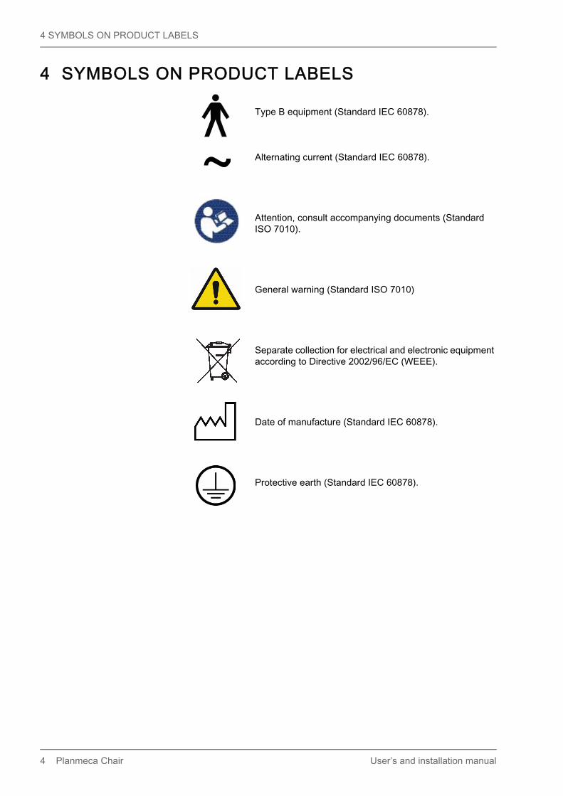
4 SYMBOLS ON PRODUCT LABELS
Type B equipment (Standard IEC 60878).
Alternating current (Standard IEC 60878).
Attention, consult accompanying documents (Standard ISO 7010).
General warning (Standard ISO 7010)
Separate collection for electrical and electronic equipment according to Directive 2002/96/EC (WEEE).
Date of manufacture (Standard IEC 60878).
Protective earth (Standard IEC 60878).
4 Planmeca Chair User’s and installation manual

5 FOR YOUR SAFETY
5 FOR YOUR SAFETYWhen driving the chair from one position to another care should be taken. In case of emergency the chair will stop when the backrest, the stop plate underneath the seat, or the stop bar or stop cover on the underside of the lifting mechanism is pressed upwards. The chair will also stop when the safety switch on the underside of the legrest is activated. The chair can be driven normally after the possible obstruction has been removed.
NOTEBecause of the chair swivel feature the stop plate located on the underside of the seat does not cover the whole surface.
CAUTIONElectromagnetic interference between the equipment and other devices can occur in very extreme condi-tions. Do not use the equipment in close conjunction with sensitive devices, or devices creating high elec-tromagnetic disturbances.
CAUTIONSwitch off the unit before using an electrosurgical knife.
CAUTIONDo not use the equipment in close conjunction with anaesthetic gas or in highly oxygenated environ-ments (oxygen content >25%).
WARNINGNo modification of this patient chair is allowed.
WARNINGTo avoid risk of electric shock, Planmeca Chair must only be connected to a supply mains with protective earth.Canada only:External fuse: max 20A branch circuit fuse.
WARNINGDo not perform maintenance procedures or replace patient chair parts while treating a patient.
PM_C
hai
r1.e
ps
Stop barStop plate
Backrest
Safetyswitch
Stop cover
User’s and installation manual Planmeca Chair 5

6 PLANMECA CHAIR
6 PLANMECA CHAIR
6.1 Main parts
CAUTIONDo not sit on the legrest.
NOTEThe optional features of the chair are described in section 9 "OPTIONAL FEATURES" on page 16.
6.2 Applied partsThe following parts of Planmeca Chair will in normal treatment situations come in contact with the patient:• upholstery• armrests• headrest• operating light post• OP-tray
4ATIntermitte
nt operation, ED8%
25 sec "ON", 3
00 sec "OFF"
220-240V~ 50/60Hz 800W
4AT
LBL-10026426
Seat
Headrest
Backrest
Lifting mechanism
On/off switch
Base
Swivel foot switchFoot control
6 Planmeca Chair User’s and installation manual

7 USING CHAIR
7 USING CHAIRThe chair can be operated manually or automatically. When the chair is used manually the foot control must be pushed and held to drive the chair to the position required.In automatic use the foot control only needs to be pushed once and the chair will move automatically to the preprogrammed chair position. Before the chair can be used in the automatic mode, check the preprogrammed automatic positions.
7.1 Switching chair onThe on/off switch is located on the base of the chair below the legrest. When the chair is switched on it will give a signal tone. The chair is now ready for use.The same switch is used to switch the chair off.
4AT
Intermittent operation, ED8%
25 sec "ON", 3
00 sec "OFF"
220-240V~ 50/60Hz 800W
4AT
LBL-10026426
4AT
Intermittent operation, ED8%
25 sec "ON", 3
00 sec "OFF"
220-240V~ 50/60Hz 800W
4AT
LBL-10026426
PM
_cha
ir_sw
itch.
eps
On/off switch
User’s and installation manual Planmeca Chair 7

7 USING CHAIR
7.2 Moving armrestsThe armrests can be moved 90° outwards. Before you move the armrest you must lift it slightly to unlock it. Both armrests can be locked into the positions presented below.
7.3 Adjusting chair headrest
7.3.1 Adjusting height of headrest
The height of the headrest can be adjusted by sliding it manually.
NOTEThe headrest can only be pulled out as far as to the MAX mark.
Chair_armrests.eps
Cu
fl3_2
1.ep
s
8 Planmeca Chair User’s and installation manual

7 USING CHAIR
7.3.2 Adjusting headrest angle
To adjust the angle of the headrest press the bar on the side of the headrest support to release the locking mechanism. Manually set the headrest to the angle required and then release the bar. When adjusting, the headrest should be supported by hand.
7.3.3 Adjusting headrest for children or short patients
The headrest can be turned around and repositioned for better head support for children or short patients.
Pull the headrest out. Turn it around so that the cushion faces backwards and push the headrest back into the chair.
Turn the cushion around (180° counterclockwise).
User’s and installation manual Planmeca Chair 9

7 USING CHAIR
Press the bar on the side of the headrest support to release the locking mechanism and position the headrest at the top of the chair.
The headrest is now repositioned. To adjust the angle of the headrest press the locking bar. Manually set the headrest into the required position and then release the bar. When adjusting, support the headrest with your other hand.
7.4 Chair swivel
If required, the chair can be swivelled 90° to the right or left. Release the locking mechanism by pressing the foot switch located on the chair base. The chair can now be manually swivelled up to 90° in either direction. Release the knob and rotate the seat until it locks to the nearest locking position (increment is 5°).
NOTEOptionally the chair can be locked to its position in the installation phase. This disables the swivel movement.
D
AB
C
hybr
swive
l_01
99A.
eps
Swivel foot switch
10 Planmeca Chair User’s and installation manual

7 USING CHAIR
7.5 Automatic legrestThe automatic legrest can be moved synchronously to the movements of the backrest, that is, when you drive the backrest down, the automatic legrest is driven up. Use the chair movement buttons to drive the patient chair. Notice that the lever underneath the legrest has to be unlocked (moved to the right) in order to move the legrest with the backrest.
The automatic legrest can be locked approximately 18° from the horizontal position. To lock the legrest the lever has to be locked to the left. Support the legrest with your other hand when locking or unlocking the lever. Notice that the backrest will move upward and downward when the legrest is locked.
PM_Chair_legrest_3.eps
Backrest
Automatic legrest
Lever
PM_chair_legrest_2.eps
Lever
Horizontal position
Approx. 18° from the horizontalposition
User’s and installation manual Planmeca Chair 11

7 USING CHAIR
7.6 Trendelenburg positionIf required, the patient chair can be inclined from the horizontal position to the Trendelenburg position. In the Trendelenburg position the legrest is in the horizontal position and the backrest is driven -4° from the horizontal position.To drive the patient chair to the Trendelenburg position, first drive the chair to the horizontal position by pushing and holding the foot control to the left. After the backrest movement has stopped, release the foot control and then push the foot control again to the left.
7.7 Driving chair to required position
NOTEIf the Planmeca Compact i Touch v2 dental unit without a chair is connected to Planmeca chair, all chair movements are disabled when driving an instrument from the dental unit.
7.7.1 Manual operationTo adjust the position of the chair, push and hold the foot control in the direction indicated on the foot control to drive the chair in the direction required. When the chair reaches the desired position, release the foot control. The foot control will only operate one movement at a time.
PM_chair_legrest_5.eps
Lever
Horizontalposition
12 Planmeca Chair User’s and installation manual

7 USING CHAIR
NOTEThe chair movement stops immediately when you release the foot control. If the stop is delayed, contact your Planmeca dealer.
D
C
A B
PM
_Cha
ir3.e
ps
D
C
A B
PM
_Cha
ir3.e
ps
D
C
A B
PM
_Cha
ir3.e
ps
D
C
A B
PM
_Cha
ir3.e
ps
Push the foot control towards the chair to drive the seat up.
Push the foot control away from the chair to drive the seat down.
Push the foot control to the left to drive the backrest down.
Push the foot control to the right to drive the backrest up.
Seat up
Seat down
Backrest down
Backrest up
User’s and installation manual Planmeca Chair 13

7 USING CHAIR
7.7.2 Automatic operationThe chair incorporates a memory in which you can store the chair positions that you want the chair to move to in the automatic mode. There are four chair positions available: the rinsing position (C) and three working positions (A, B, D). The positions have been preprogrammed at the factory, and can be changed by the user. See section 8 "PROGRAMMING CHAIR POSITIONS" on page 15.
NOTEIt is possible to disable the automatic movement to the preprogrammed positions by connecting a jumper to the Power supply PCB. Contact your Planmeca dealer, if needed.
Push the foot control briefly to the position (A, B, C, or D) where the preprogrammed chair position is stored. The chair will move automatically to the preprogrammed position.
NOTEPosition C is the rinsing position. Push the foot control briefly to position C and the chair will move to the preprogrammed rinsing position. The chair remembers its previous working position; push the foot control again briefly to position C to return back to this previous position.
To stop the chair from moving before it reaches the preprogrammed position, push the foot control in any direction or press the backrest, the stop plate, or the stop bar, or, press the stop cover on the underside of the lifting mechanism upwards.
If you stop the chair by lifting the backrest, the stop plate, stop bar or stop cover before it reaches its preprogrammed position, you will hear a signal tone. You will also hear a signal tone every two seconds when the stop switch is active. To operate the chair again, use the foot control.
If you wish to adjust the position of the chair when it has reached its preprogrammed position, simply use the foot control in manual mode to drive the chair to the desired position.
D
C
A B
PM
_Cha
ir3.e
ps
PM_C
hai
r1.e
ps
Stop barStop plate
Backrest
Stop cover
14 Planmeca Chair User’s and installation manual

8 PROGRAMMING CHAIR POSITIONS
8 PROGRAMMING CHAIR POSITIONSThe chair incorporates a memory in which you can store the chair positions that you want the chair to move to in the automatic mode. There are four chair positions available: the rinsing position (C) and three working positions (A, B, D). The positions have been preprogrammed at the factory, and can be changed by the user as follows.
NOTEIn case your chair is equipped with an optional remote control panel, you can also program the chair positions using the control panel keys, see section 9.3.3 "Programming chair positions" on page 19.
NOTEIf the Planmeca Compact i Touch v2 dental unit without a chair is connected to Planmeca chair, the chair positions can also be programmed from the dental unit. When the chair positions are saved to the chair, a signal is heard.
1. With the foot control, set the height of the chair and the inclination of the backrest to the positions you require.
2. Lift the stop plate briefly twice to enter the programming mode. When the programming mode is active you will hear a long signal tone every two seconds.
3. Push and hold the foot control in the direction of the position (A, B, C, or D) where you wish to store the chair position. You will hear the same signal tone that you hear when the chair is switched on, which indicates that the chair position has been programmed into the memory.
If you want to exit the programming mode without changing the chair position, lift the stop plate briefly.
NOTEIf you interrupt programming for over 25 seconds, the chair automatically exits the programming mode without storing the new position.
PM_C
hai
r1.e
ps
Stop plate
D
C
A B
PM
_Cha
ir3.e
ps
User’s and installation manual Planmeca Chair 15

9 OPTIONAL FEATURES
9 OPTIONAL FEATURES
9.1 Child cushion set
Position the child cushion set onto the chair as shown in the figure. Support the backrest cushion with your hand and guide the patient onto the chair.
NOTELift the backrest cushion upwards if it descends when the backrest is in vertical position.
9.2 Operating light post and OP-tray
The Planmeca SingLED operating light or an OP-tray can optionally be attached to Planmeca Chair. Their installation requires that an adapter be installed between the patient chair and the operating light post.
1. Operating light post2. OP-tray3. Adapter
CAUTIONWhen driving down the chair, make sure that nothing gets squeezed between the adapter and the floor.
laps
ityyn
y_02
99A
.eps
1
2
3
16 Planmeca Chair User’s and installation manual
9 OPTIONAL FEATURES
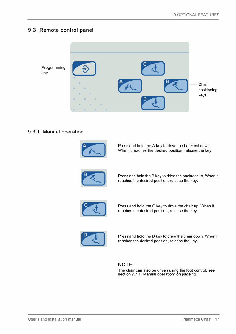
9.3 Remote control panel
9.3.1 Manual operation
Press and hold the A key to drive the backrest down. When it reaches the desired position, release the key.
Press and hold the B key to drive the backrest up. When it reaches the desired position, release the key.
Press and hold the C key to drive the chair up. When it reaches the desired position, release the key.
Press and hold the D key to drive the chair down. When it reaches the desired position, release the key.
NOTEThe chair can also be driven using the foot control, see section 7.7.1 "Manual operation" on page 12.
Chair
Programming
key
positioningkeys
User’s and installation manual Planmeca Chair 17

9 OPTIONAL FEATURES
9.3.2 Automatic operationThe chair incorporates a memory in which you can store the chair positions that you want the chair to move to in the automatic mode. There are four chair positions available: the rinsing position (C) and three working positions (A, B, D). The positions have been preprogrammed at the factory, and can be changed by the user. See section 9.3.3 "Programming chair positions" on page 19 or 8 "PROGRAMMING CHAIR POSITIONS" on page 15.
NOTEIt is possible to disable the automatic movement to the preprogrammed positions by connecting a jumper to the Power supply PCB. Contact your Planmeca dealer, if needed.
Press briefly the required chair position key. The chair will move automatically to the preprogrammed position.
NOTEPosition C is the rinsing position. Press the C key briefly and the chair will move to the preprogrammed rinsing position. The chair remembers its previous working position; press the C key briefly again to return back to this previous position.
To stop the chair from moving before it reaches the preprogrammed position, push the foot control in any direction or press any of the chair positioning keys. You can also press the backrest, the stop plate, or the stop bar, or, press the stop cover on the underside of the lifting mechanism upwards. If you stop the chair by lifting the backrest, the stop plate, stop bar or stop cover before it reaches its preprogrammed position, you will hear a signal tone. You will also hear a signal tone every two seconds when the stop switch is active. To operate the chair again use the foot control or the control panel keys.If you wish to adjust the position of the chair when it has reached its preprogrammed position, simply use the foot control or the control panel in manual mode to drive the chair to the desired position.
NOTEThe chair can be driven to the automatic positions also using the foot control, see section 7.7.2 "Automatic operation" on page 14.
PM_C
hai
r1.e
ps
Stop barStop plate
Backrest
Stop cover
18 Planmeca Chair User’s and installation manual

9 OPTIONAL FEATURES
9.3.3 Programming chair positionsThe chair incorporates a memory in which you can store the chair positions that you want the chair to move to in the automatic mode. There are four chair positions available: the rinsing position (C) and three working positions (A, B, D). The positions have been preprogrammed at the factory, and can be changed by the user as follows.
NOTEThe chair positions can also be programmed using the foot control, see section 8 "PROGRAMMING CHAIR POSITIONS" on page 15.
1. Move the chair to the desired position using the foot control or the chair keys on the remote control panel.
2. Press the programming key to enter the programming mode.When the programming mode is active you will hear a long signal tone every two seconds.
3. Press and hold the desired chair position key where to store the chair position (A, B, C, or D). You will hear the same signal tone that you hear when the chair is switched on, which indicates that the chair position has been programmed into the memory.
If you want to exit the programming mode without changing the chair position, press the programming key briefly.
NOTEIf you interrupt programming for over 25 seconds, the chair automatically exits the programming mode without storing the new position.
User’s and installation manual Planmeca Chair 19
9 OPTIONAL FEATURES
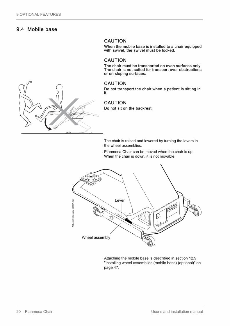
9.4 Mobile base
CAUTIONWhen the mobile base is installed to a chair equipped with swivel, the swivel must be locked.
CAUTIONThe chair must be transported on even surfaces only. The chair is not suited for transport over obstructions or on sloping surfaces.
CAUTIONDo not transport the chair when a patient is sitting in it.
CAUTIONDo not sit on the backrest.
The chair is raised and lowered by turning the levers in the wheel assemblies.Planmeca Chair can be moved when the chair is up. When the chair is down, it is not movable.
Attaching the mobile base is described in section 12.9 "Installing wheel assemblies (mobile base) (optional)" on page 47.
Whe
elie
Bar
ass
y_03
99A
.eps
Wheel assembly
Lever
20 Planmeca Chair User’s and installation manual

10 MAINTENANCE
10 MAINTENANCE
10.1 Cleaning upholsteryA mild soap and warm water solution can be used to wipe off stains and spills. Let the upholstery air dry.
10.1.1 DisinfectingThe Ultra Relax upholstery stands up to routine disinfections with ethyl alcohol.For disinfecting the upholstery between each patient we recommend Dürr FD 333 or a similar product. After the working day we recommend that you disinfect the upholstery with Dürr FD 312 or a similar product.Once a week, we recommend that you clean and treat the upholstery with Dürr FD 360. Wipe away any excess oil after the treatment.
10.2 Cleaning chair baseThe chair base can be cleaned with a soft cloth moistened with a mild cleaning solution. Do not use abrasive cleaning agents.
10.2.1 DisinfectingFor disinfecting, we recommend Dürr FD 312 or a similar disinfecting solution.
User’s and installation manual Planmeca Chair 21

10 MAINTENANCE
10.3 Replacing fuses
CAUTIONWhen servicing the unit, always first switch the unit off by removing the plug from the wall outlet and then wait for 2 minutes before touching any electrical parts.
CAUTIONNote that the mains voltage is always present at the mains terminal under the main control PCB cover, even if the unit is switched off from its own mains switch.
The fuses are located on the base of the chair below the on/off switch. Turn the fuse holder counterclockwise to remove it from the chair. Replace the old fuse with a new one of the same type and rating. Put back the fuse holder and switch the chair on.
22 Planmeca Chair User’s and installation manual

11 CHAIR SIGNAL TONES
11 CHAIR SIGNAL TONESThe different modes of the chair as well as some of the erroneous situations are expressed with signal tones. If the Planmeca Compact i control panel is connected and service mode is entered, the unique error code can be read from the display.
11.1 Error tonesThe error tones in group 1 are always enabled, whereas the error tones in groups 2 - 5 are disabled. To enable the error tones in groups 2 - 5, for example for troubleshooting purposes, contact your Planmeca dealer.
11.1.1 Group 1 - Error codes with a single beep every two secondsAt least one of the safety switches has been activated. The chair and backrest can only be driven in the upwards direction. The chair’s operation returns to normal automatically after the obstructing items have been removed from under the chair. Should this happen without any visible cause, most probably the emergency switch of the backrest motor needs to be re-adjusted.
11.1.2 Group 2 - Error codes with two beeps every two secondsIf the error tone is continuous (over ten seconds), the voltage signal received from the lift motor position sensor is below (short circuit) or above (open circuit) the programmed limits. Either the lift motor position sensor is out of calibration or the sensor and/or its cable is broken.If the error tone disappears after ten seconds, the voltage signal received from the lift motor position sensor is within the programmed limits, but it does not change or changes in the wrong direction when the motor is run. Either the lift motor position sensor is not in contact with the motor’s worm screw or the processor PCB is broken.
Table 1: Error codes with single beep every two seconds
Code Name Description
1 ERROR_SAFETY_LOOP_BROKEN Safety loop is broken.
2 ERROR_PROG_STOP_PLATE_PRESSED_WHEN_DRIVING
Stop (program) plate was pressed when driving.
2 s
2 s
User’s and installation manual Planmeca Chair 23

11 CHAIR SIGNAL TONES
11.1.3 Group 3 - Error codes with three beeps every two secondsIf the error tone is continuous (over ten seconds), the voltage signal received from the backrest motor position sensor is below (short circuit) or above (open circuit) the programmed limits. Either the backrest motor position sensor is out of calibration or the sensor and/or its cable is broken.If the error tone disappears after ten seconds, the voltage signal received from the backrest motor position sensor is within the programmed limits, but it does not change or changes in the wrong direction when the motor is run. Either the backrest motor position sensor is not in contact with the motor’s worm screw or the processor PCB is broken.
11.1.4 Group 4 - Error codes with four beeps every two secondsThe lift or backrest motor runs without a command from the foot control or control panel. The processor PCB is broken.
Table 2: Error codes with two beeps every two seconds
Code Name Description
3 ERROR_LIFT_POT_MISSING Lift position sensor is missing.
4 ERROR_LIFT_POT_OUT_OF_CAL Lift position sensor is out of calibration.
5 ERROR_LIFT_DOES_NOT_MOVE Lift motor does not move or it moves to wrong direction.
Table 3: Error codes with three beeps every two seconds
Code Name Description
6 ERROR_BACKREST_POT_MISSING Backrest position sensor is missing.
7 ERROR_BACKREST_POT_OUT_OF_CAL Backrest position sensor is out of calibration.
8 ERROR_BACKREST_DOES_NOT_MOVE Backrest motor does not move or it moves to wrong direction.
Table 4: Error codes with four beeps every two seconds
Code Name Description
9 ERROR_LIFT_MOVES_WITHOUT_CMD Lift motor moves without command.
10 ERROR_BACKREST_MOVES_WITHOUT_CMD
Backrest motor runs without command.
2 s
2 s
24 Planmeca Chair User’s and installation manual

11 CHAIR SIGNAL TONES
11.1.5 Group 5 - Error codes with five beeps every two seconds
Hardware problem. See table 5.
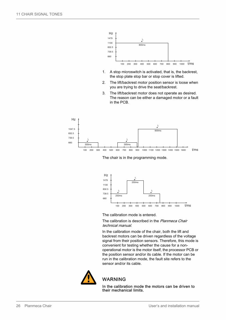
11.2 Other signal tonesIn the following figures a signal tone is shown with a note, and the pitch of sound is expressed in Hz.
1. The chair is switched on.2. An automatic chair position has been programmed
into the memory.
Table 5: Error codes with five beeps every two seconds
Code Name Description
11 ERROR_FLASH_ERROR Auto position read or write failed. Try power off/on or replace PCB.
12 ERROR_INPUT_VOLTAGE_MEAS_ERROR Input AC voltage not detected. PCB is powered from DC voltage or it is broken. Fix mains input or replace PCB.
13 ERROR_INPUT_VOLTAGE_LOW Input AC voltage is below minimum level.
14 ERROR_INPUT_VOLTAGE_HIGH Input AC voltage is above maximum level.
15 ERROR_INPUT_FREQUENCY_LOW Input AC frequency is below minimum level.
16 ERROR_INPUT_FREQUENCY_HIGH Input AC frequency is above maximum level.
17 ERROR_INPUT_PHASE_MISSING One of the 24 VAC phases is missing. Check connections between transformer and PCB.
18 ERROR_UNSUPPORTED_PCB_VER PCB version is either too old or new for current software version. Update software or replace PCB.
19 ERROR_STICKY_KEY Some user interface button is stuck. Check foot controls, additional keyboards and internal wirings.
2 s
100 200 300 400 500 600 t/ms
Hz
120ms
120ms
120ms660
739.5
832.5
1100
1479
User’s and installation manual Planmeca Chair 25
11 CHAIR SIGNAL TONES
1. A stop microswitch is activated, that is, the backrest, the stop plate stop bar or stop cover is lifted.
2. The lift/backrest motor position sensor is loose when you are trying to drive the seat/backrest.
3. The lift/backrest motor does not operate as desired. The reason can be either a damaged motor or a fault in the PCB.
The chair is in the programming mode.
The calibration mode is entered.The calibration is described in the Planmeca Chair technical manual.In the calibration mode of the chair, both the lift and backrest motors can be driven regardless of the voltage signal from their position sensors. Therefore, this mode is convenient for testing whether the cause for a non-operational motor is the motor itself, the processor PCB or the position sensor and/or its cable. If the motor can be run in the calibration mode, the fault site refers to the sensor and/or its cable.
WARNINGIn the calibration mode the motors can be driven to their mechanical limits.
100 200 300 400 500 600 700 800 900 1000 t/ms
Hz
800ms
660
739.5
832.5
1100
1479
100 200 300 400 500 600 700 800 900 1000 1100 1200 1300 1400 1500 1600 t/ms
Hz
300ms 300ms
600ms
660
739.5
832.5
1047.5
100 200 300 400 500 600 700 800 900 1000 t/ms
Hz
250ms 250ms
250ms
660
739.5
832.5
1100
1479
26 Planmeca Chair User’s and installation manual

12 INSTALLING PLANMECA PATIENT CHAIR
12 INSTALLING PLANMECA PATIENT CHAIR
12.1 Driving chair out from transportation positionPlug the chair to a mains outlet and switch it on (see section 7.1 "Switching chair on" on page 7).Drive the seat upwards and remove the transportation support piece from the stop bar.
pakk
ausp
ala.
eps
Stop bar
Transportation support piece
Stop bar Lifting mechanism
User’s and installation manual Planmeca Chair 27

12 INSTALLING PLANMECA PATIENT CHAIR
12.2 Attaching chair to floor
CAUTIONThe chair must be bolted to the floor before attaching the upholsteries, and before installing any equipment to the chair. The chair must be bolted to the floor even if the loca-tion is temporary (e.g. in trade shows).Do not remove the caution label from the chair seat.
NOTECheck that the floor is straight enough, maximum clearance between the chair base and floor is 1.5 mm (0.06 in.).
NOTEIf the power supply cable plug is used as a means of isolation, ensure that the power supply cable plug is readily accessible when needed. Do not position the chair so that it is difficult to access the plug.
There are four fastening screw holes on the chair base. Fasten the chair to the floor with four screws. Use the chair base as a template and mark the positions of the fastening screw holes to the floor.
If the floor is made of concrete, use the M10x30 DIN 912 screws and expansion anchors. Drill four ø12mm (0.47 in.) holes, 40 mm (1.57 in.) in depth, and place the expansion anchors into them. Make sure that the end of the anchor is under the floor surface, but not more than 2 mm (0.08 in). If the floor is made of wood, use the ø8x60 DIN 571 lag screws. Drill four ø5mm (0.2 in.) holes, 50...55 mm (2.0...2.2 in.) in depth. Do not use expansion anchors with wooden floors. See figure below.
asen
nusk
uva.
eps
Fastening screws
Fastening screws
28 Planmeca Chair User’s and installation manual

12 INSTALLING PLANMECA PATIENT CHAIR
NOTETighten the screws carefully (40Nm). Check that the base is firmly against the floor and the chair does not move when trying to tilt it.
NOTEThe mounting hardware must withstand a 200 kg (2000 N, 445 lbf) withdrawal force at each mounting point.
Attach the chair to the floor and replace the foot control cover and the mains junction plate.Attach the protective strips to the chair base.
asen
nusk
uva3
.eps
Concrete floor Wooden floor
M10x30 DIN 912
Ø8x60 DIN 571
Ø12mm (0.4 in.)
70mm (2.76 in.)
Ø 5mm (0.2 in.)
50..55mm (2.0 in.)
Ø10,5 mm DIN 125
Ø10,5 mm DIN 125Sormat LA 10
Cha
ir_st
ripes
.eps
User’s and installation manual Planmeca Chair 29

12 INSTALLING PLANMECA PATIENT CHAIR
12.3 Changing voltage
CAUTIONWhen servicing the unit, always switch the unit off.
CAUTIONNote that the mains voltage is always present at the mains terminal under the main control PCB cover, even if the unit is switched off from its own mains switch.
The Planmeca patient chair is suited for three different voltages: 220-240 V, 115 V and 100 V. The voltage selectors are presented below. All three selectors are included in the chair delivery.
For 220-240 V, 100 V, and 115 V.
30 Planmeca Chair User’s and installation manual

12 INSTALLING PLANMECA PATIENT CHAIR
The used voltage can be changed by simply changing the voltage selector inside the mains junction box.
After the voltage is changed the label attached to the junction plate as well as the fuses must be changed.
Change this label.
User’s and installation manual Planmeca Chair 31

12 INSTALLING PLANMECA PATIENT CHAIR
Note, that if the chair is attached to a fixed power source only one fuse is used. Norway is an exception, two fuses are used also with fixed power source.Changing power source from plug to fixed is described in section 12.4 "Changing power source" on page 33.
CAUTIONMake sure that you select the correct label! See fig-ure on next page.
Check the correct fuse values from the technical specifications (14 "TECHNICAL SPECIFICATIONS" on page 51) and from the label you attached.
Change the correct fuse(s) according to the instructions given in section 10.3 "Replacing fuses" on page 22. Note, that also the fuse nests must be replaced.
Voltage 220-240V, plug
Voltage 115V, plug
Voltage 100V, plug
Voltage 220-240V, fixed power source
Voltage 115V, fixed power source
Voltage 100V, fixed power source
32 Planmeca Chair User’s and installation manual

12 INSTALLING PLANMECA PATIENT CHAIR
12.4 Changing power sourceWhen the Planmeca patient chair is delivered from the factory, it is equipped with a power supply cable with plug. If, however, the chair is to be attached to a fixed power source, the N fuse has to be bypassed.
CAUTIONWhen servicing the unit, always first switch the unit off by removing the plug from the wall outlet and then wait for 2 minutes before touching any electrical parts.
CAUTIONNote that the mains voltage is always present at the mains terminal under the main control PCB cover, even if the unit is switched off from its own mains switch.
CHAIRPCB
LL
LN
PE
PE
PE
N Fuse shorted
N Fused
N FusedPlug, two fuses
Fixed power source,one fuse
User’s and installation manual Planmeca Chair 33

12 INSTALLING PLANMECA PATIENT CHAIR
To bypass the N fuse, follow the instructions below.1. Open the cover of the mains junction box.
The picture below shows the factory default configuration.
2. To bypass the N fuse, move the blue wire from connector N fused to N fuse shorted.
34 Planmeca Chair User’s and installation manual

12 INSTALLING PLANMECA PATIENT CHAIR
3. If needed, change the used voltage by changing the voltage selector. For instructions, see section 12.3 "Changing voltage" on page 30.
4. Remove the power supply cable and attach the correct label to the mains junction plate. The different labels are shown in section 12.3 "Changing voltage" on page 30.
5. Close the cover of the mains junction box.
12.5 Attaching upholsteryThe chair upholsteries are to be attached into their positions over the chair castings.Remove the seat, backrest, headrest and armrests upholsteries from the packing. The upholsteries are equipped with velcro tapes that will attach them to the chair castings. In addition to the tapes, some screws are used to secure the upholsteries into position.
Change this label.
User’s and installation manual Planmeca Chair 35

12 INSTALLING PLANMECA PATIENT CHAIR
12.5.1 Attaching seat upholsterySlide the attachment plates to their positions at the seat upholstery backplate as shown in the figure below.
Slide the seat upholstery towards the backrest casting in a way that the attachment screw goes into the groove of the upholstery’s backplate. You can bend the seat upholstery carefully from its sides to make the attachment easier. If the attachment screw does not go into the groove, the screw can be slightly opened by turning it clockwise. Make sure that you have slid the upholstery as far as it goes.
Up
ho
lst_
05_1
.ep
s
Attachment plates
PM
_Cha
ir9.e
ps
Attachment screw
36 Planmeca Chair User’s and installation manual
12 INSTALLING PLANMECA PATIENT CHAIR
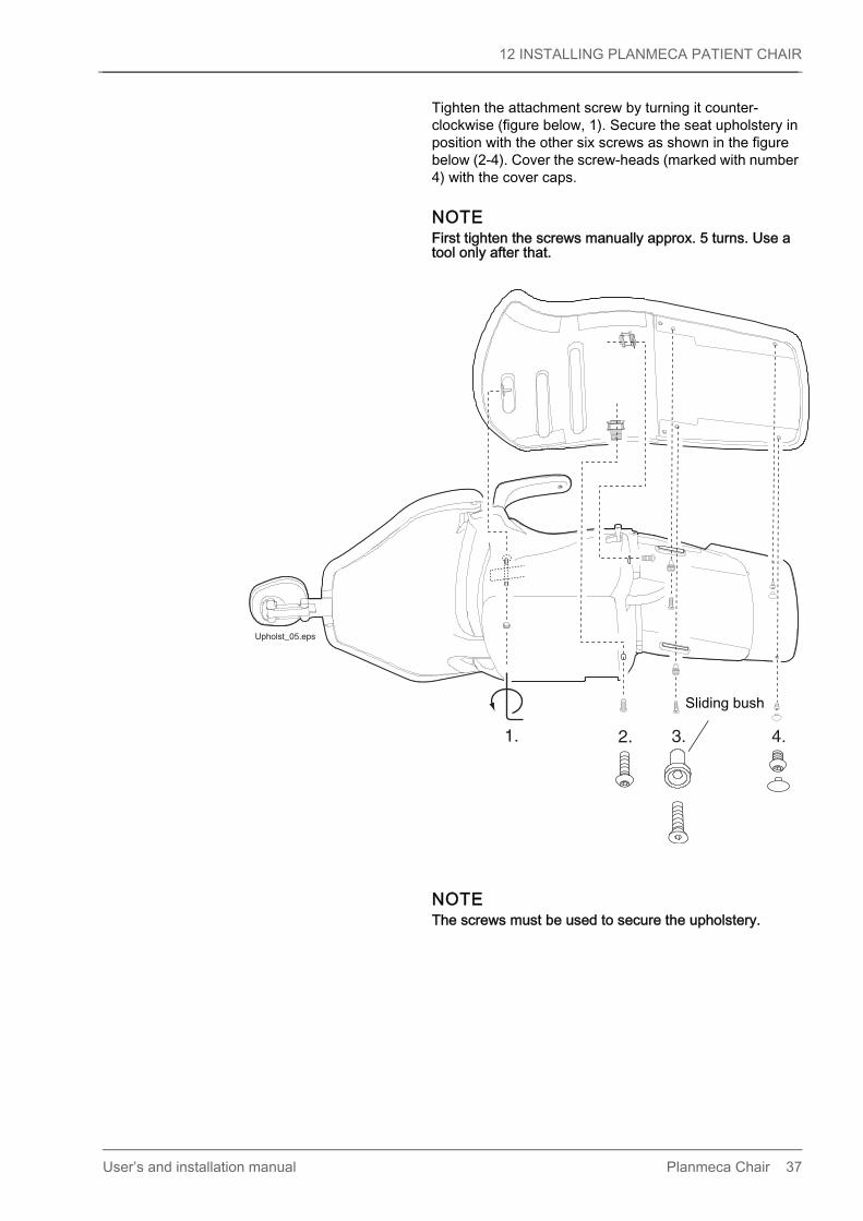
Tighten the attachment screw by turning it counter-clockwise (figure below, 1). Secure the seat upholstery in position with the other six screws as shown in the figure below (2-4). Cover the screw-heads (marked with number 4) with the cover caps.
NOTEFirst tighten the screws manually approx. 5 turns. Use a tool only after that.
NOTEThe screws must be used to secure the upholstery.
2. 3. 4.1.
Upholst_05.eps
Sliding bush
User’s and installation manual Planmeca Chair 37

12 INSTALLING PLANMECA PATIENT CHAIR
Cover the attachment screw on the chair underside by placing the installation plate (white arrow) and the cover plate (black arrow) as shown in the figure below.
Attach the cover plate to its position with an attachment screw using a 2 mm Allen key.
38 Planmeca Chair User’s and installation manual

12 INSTALLING PLANMECA PATIENT CHAIR
12.5.2 Attaching backrest upholsteryCover the lower velcro on the backrest with, for example, plastic sheets and adjust the attachment hook so that a 5 mm Allen key fits under it.
Place the backrest upholstery onto the backrest casting so that the upper edge of the upholstery is approx. 1 cm (0.4 in.) inside from the casting edge.Bend the upper part of the backrest upholstery firmly from its sides (1) and slide the backrest upholstery towards you in a way that the attachment hook goes into the groove of the upholstery’s backplate (2).
User’s and installation manual Planmeca Chair 39

12 INSTALLING PLANMECA PATIENT CHAIR
Remove the plastic sheets and press the upholstery to its position. Press first the centre of the upholstery and then all the edges to attach all the velcros to their counterparts.Note that the upholstery should come over the casting.
40 Planmeca Chair User’s and installation manual

12 INSTALLING PLANMECA PATIENT CHAIR
12.6 Attaching headrest
Remove the transportation plate from the backrest opening.
Slide the headrest arm inside the backrest.
Then place the headrest upholstery on the headrest casting. Secure it into position by tightening the screw on the back of the headrest casting.
Mou
nthe
adr.e
ps1
2Headrest arm
Backrest
Transportation plate
User’s and installation manual Planmeca Chair 41

12 INSTALLING PLANMECA PATIENT CHAIR
12.7 Attaching armrestsIf you are installing the left armrest that turns to the left, see the instructions given in section 12.7.1 "Planmeca Chair left armrest (turns to left)" on page 45.Remove the white cover plugs from the seat casting.
Place the armrest attachment pin to the opening on the seat in a position shown in the figures below (note the direction of the groove).
Armrest attachment pin Groove
42 Planmeca Chair User’s and installation manual

12 INSTALLING PLANMECA PATIENT CHAIR
Attach the pin to the seat with an attachment screw. Tighten the attachment screw with 45 Nm force.
Attach the armrest upholstery to the armrest casting with two 2x50 torx screws using TX 25 key.
arm
rest
1.ep
s
Armrest casting
Armrest upholstery
User’s and installation manual Planmeca Chair 43
12 INSTALLING PLANMECA PATIENT CHAIR
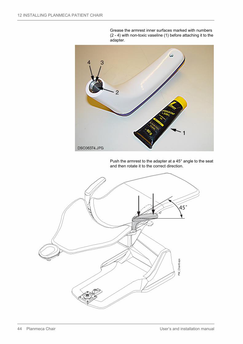
Grease the armrest inner surfaces marked with numbers (2 - 4) with non-toxic vaseline (1) before attaching it to the adapter.
Push the armrest to the adapter at a 45° angle to the seat and then rotate it to the correct direction.
PM
_Cha
ir8.e
ps
45˚
44 Planmeca Chair User’s and installation manual

12 INSTALLING PLANMECA PATIENT CHAIR
12.7.1 Planmeca Chair left armrest (turns to left)Remove the white cover plug from the seat casting. Place the armrest attachment pin to the opening on the seat in a position shown in the figures below (note the direction of the groove). Attach the pin to the seat with an attachment screw. Tighten the attachment screw firmly
Attach the armrest to the attachment pin according to the instructions in section 12.7 "Attaching armrests" on page 42. When needed, the armrest can be turned left to the position shown in the figure below.
Groove
User’s and installation manual Planmeca Chair 45

12 INSTALLING PLANMECA PATIENT CHAIR
12.8 Removing swivel mechanism locking screwThe swivel mechanism is locked during transportation with a locking screw. Note, that the chair must be attached to the floor before removing the screw.
CAUTIONIf you do not wish to take the swivel feature into use, do not remove the swivel mechanism locking screw.
CAUTIONWhen the chair is equipped with a mobile base (see section 9.4 "Mobile base" on page 20), the swivel mechanism must always be locked.
Drive the seat to the uppermost position. Remove the M8x16 DIN 912 screw from the swivel mechanism. Detach the label from the height control cover plate.
NOTEKeep the removed screw for possible later use, for example, for unit adapter attachment.
swiv
el-lo
ck.e
ps
Detach the label
M8x16 DIN 912 screw
46 Planmeca Chair User’s and installation manual

12 INSTALLING PLANMECA PATIENT CHAIR
12.9 Installing wheel assemblies (mobile base) (optional)
CAUTIONWhen the chair is equipped with a mobile base the swivel mechanism must be locked, see section 12.8 "Removing swivel mechanism locking screw" on page 46.
CAUTIONDo not install a dental unit or any other equipment to the chair with a mobile base.
CAUTIONDo not transport the chair when a patient is sitting in the chair.
Remove the protective strips and the plastic plugs (5+5 pcs.) from the chair base.Enlarge the fastening holes (5+5 pcs.) with a ø5.1 mm drill.Turn the chair carefully to its side. Attach the wheel assemblies with the M5 x 8 DIN 7984 screws (5+5 pcs.) according to the figure below.
4ATIntermitte
nt operation, ED8%
25 sec "ON", 3
00 sec "OFF"
220-240V~ 50/60Hz 800W
4AT
LBL-10026426
PM
_cha
ir_w
heel
ie b
ar a
ssy.
eps
Plastic plugs
Fastening holesProtective strip
User’s and installation manual Planmeca Chair 47

12 INSTALLING PLANMECA PATIENT CHAIR
12.10 Installing remote control panel (optional)
NOTEMake sure that the software revision of the chair is 1.03 or later. Change the software if needed.
NOTEIf the chair is attached to the floor, it must be detached before the remote control panel cable is routed to the Power supply PCB.
The control panel adapter can be attached either above or below the surface (see figure below). In case the surface is made of wood, attach the adapter to its position with the three EJOT DG 4x25 screws supplied with the control panel. For other surface types, use screws that are suitable for the used surface. Route the control panel cable through the adapter. Push the control panel into the adapter and secure it to the adapter with the M3x3 DIN 914 fastening screw.
Remove the mains junction plate (see figure in section 12.2 "Attaching chair to floor" on page 28).Route the control panel cable through the opening in the mains junction plate.Attach the connector to the control panel cable according to the figure below (blue -> 1; yellow -> 2; red -> 3).
PM
_Cha
ir_re
m2.
eps
Remote control panel
Control panel cable
AdapterControl panel cable
Fastening screw
Fastening screw
48 Planmeca Chair User’s and installation manual

12 INSTALLING PLANMECA PATIENT CHAIR
Connect the control panel cable to the connector J18 on the Power supply PCB.
Attach the chair to the floor according to the instructions in section 12.2 "Attaching chair to floor" on page 28.Attach the mains junction plate and the protective strip to their positions.
RED
YELLOW
10000 mm
BLUEBLUE
RED
YELLOW
PFK 4*0.22 mm code 000067692
1
2
4
3
5
123
1
2
3
PM
_cha
ir_re
m4.
eps
Control panel cable
Power Supply PCB
J18
User’s and installation manual Planmeca Chair 49

13 DISPOSAL OF CHAIR
13 DISPOSAL OF CHAIRIn order to reduce the environmental load over the product’s entire lifecycle, Planmeca products are designed to be as safe as possible to manufacture, use and dispose of.Parts which can be recycled should always be taken to the appropriate processing centres, after hazardous waste has been removed. Disposal of obsolete units is the responsibility of the waste possessor.All parts and components containing hazardous materials must be disposed of in accordance with waste legislation and instructions issued by the environmental authorities. The risks involved and the necessary precautions must be taken into account when handling waste products.
Table 6: Disposal of parts and components
Part Main materials for disposal
Recyclable material
Waste disposal site
Hazardous waste
(separate collection)
Frame and covers- metal
- plastic
- rubber
AluminiumGalvanised steelStainless steel
PUROther plastics
XXX
XX
X
Motor (X)
PCBs (X)
Cables andtransformers
CopperSteel
XX
Packing WoodCardboard, Paper
XXX
Other parts X
50 Planmeca Chair User’s and installation manual

14 TECHNICAL SPECIFICATIONS
14 TECHNICAL SPECIFICATIONSConstruction Cast alloy (all metal)Weight 120 kg (290 lbs.)Backrest angle 25° upright from vertical
90° lowest from verticalSwivel ±90°, total 180°Operation Electromechanical (2 motors)Control MicroprocessorAmbient temperature Operating +15 °C to +35 °C (59 °F to 95 °F)
Storage -5 °C to +60 °C (23 °F to 140 °F)Ambient air pressure 800 hPa to 1060 hPa (12 psi to 15 psi)Relative humidity 5% RH to 95% RH; non-condensing humidityAltitude < 2000 m (less than 1.25 miles)Power requirements 3A/220-240 VAC 50Hz/60Hz
6A/100, 115 VAC 50Hz/60HzED 8% 25 sec. “ON”, 300 sec. “OFF”
Electrical classification Class I, type BFoot control Class IPx1
Maximum lifting capacity, excluding the weight of additional equipmentIEC 60601-1 Second edition 1988-12 135 kgIEC 60601-1 Third edition 2005-12 160 kg
Maximum allowed weight of additional equipment to be attached to the chair55 kg
Maximum allowed torque caused by additional equipment on chair adapter interface or on Planmeca SingLED / OP tray adapter 365 Nm
Maximum allowed weight of additional equipment on Planmeca SingLED / OP tray adapter50 kg
Original manufacturerPLANMECA Oy, Asentajankatu 6, FIN-00880, Helsinki, FINLANDPhone: +358-20-7795 500, fax: +358-20-7795 555
220-240 V~ 115 V~ 100 V~
Plug Fuse 2 x F 4 A H 250VBussmann S501-4-RSchurter 0001.1010
2 x F 8 A H 250VBussmann S501-8-RSchurter 0001-1013
2 x F 8 A H 250VBussmann S501-8-RSchurter 0001-1013
Label LBL-10026426 LBL-10027254 LBL-10027253
Fixed Fuse 1 x F 4 A H 250V 1 x F 8 A H 250V 1 x F 8 A H 250V
Label LBL-10027258 LBL-10027256 LBL-10027255
User’s and installation manual Planmeca Chair 51
14 TECHNICAL SPECIFICATIONS
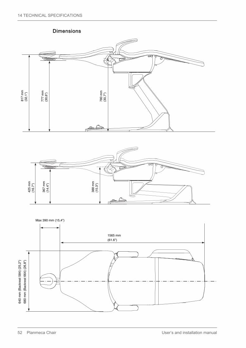
Dimensions
388
mm
(15.
3")
367
mm
(14.
4")
425
mm
(16.
7")
780
mm
(30,
7")
777
mm
(30,
6")
817
mm
(32,
1")
(61.6")1565 mm
640
mm
(B
ackr
est 5
84)
(25,
2")
680
mm
(B
ackr
est 6
64)
(26,
8")
Max 390 mm (15,4")
52 Planmeca Chair User’s and installation manual

14 TECHNICAL SPECIFICATIONS
PM
_Cha
ir7.e
ps
2035
- 2
215
mm
(80,
1" -
87,
2")
1810 - 1990 mm
(71.3" - 78.3")
Swivel angle ±90°
Backrest angle 65°
User’s and installation manual Planmeca Chair 53


Planmeca Oy | Asentajankatu 6 | 00880 Helsinki | Finland
tel. +358 20 7795 500 | fax +358 20 7795 555 | [email protected] | www.planmeca.com