Embed Size (px)
Citation preview
GEIndustrial Solutions
User/Installation Manual for 4.76kV -15kV SecoBloc
Index
General
Scope ...........................................................................................................3
Standards .................................................................................................3
Operating conditions ...........................................................................3
Technical specification ..............................................................3
Basic structure
Features .....................................................................................................4
Operation .................................................................................................4
Circuit Breaker Compartment ........................................................5
Interlocks......................................................................................6
Transportation and storage
Condition on delivery ...........................................................................7
Transport ..................................................................................................7
Storage ......................................................................................................7
Dimensions and Weight ............................................................8
Circuit Breaker Installation and Removal ..............................9
Preparations.............................................................................................9
Move the circuit breaker from test position to connected position ...........................................................................10
Move the truck from connected position to test position ..........................................................................................10
Circuit Breaker Operation .......................................................10
Trouble Shooting .......................................................................11
Accessories / Operating Tools ................................................11
Installation details of SecoBloc with switchgear ................12
Busbar Installation ...................................................................13
Recommended Torque Values ................................................13
Ring CT Installation ..................................................................14
User/Installation Manual for 4.76kV -15kV SecoBloc3
General
ScopeSecoBloc modules are completely assembled compartments designed to house GE’s SecoVac VB2+ vacuum circuit breakers. The modules can be stacked for two-high switchgear configurations, and mounted side-by side to form switchgear lineups. The OEM is responsible for supplying a rear section for main bus and cable connections, as well as the main and riser bus itself.
The switchgear is for applications in 4.76-15 kV power systems up to 3000A, with maximum short time withstand current up to 40kA and are compliant with the IEEE C37.20.2 standard for 60Hz.
SecoBloc - BM: Breaker compartment enclosure.
Standards and specificationsThe product complies with IEEE C37.20.2
Operating conditions The switchgear is designed for normal service conditions of indoor switchgear as per publication IEEE C37.20.2. The following limit values, among others, apply:
• Ambient temperature– Maximum + 40°C– 24h-Medium +35°C– Minimum -15°C
• Humidity– Highest average value measured over 24 hours
– Relative humidity 95%– Highest average value measured over 1 month
– Relative humidity 90%• The maximum site altitude is 1000 m above sea level
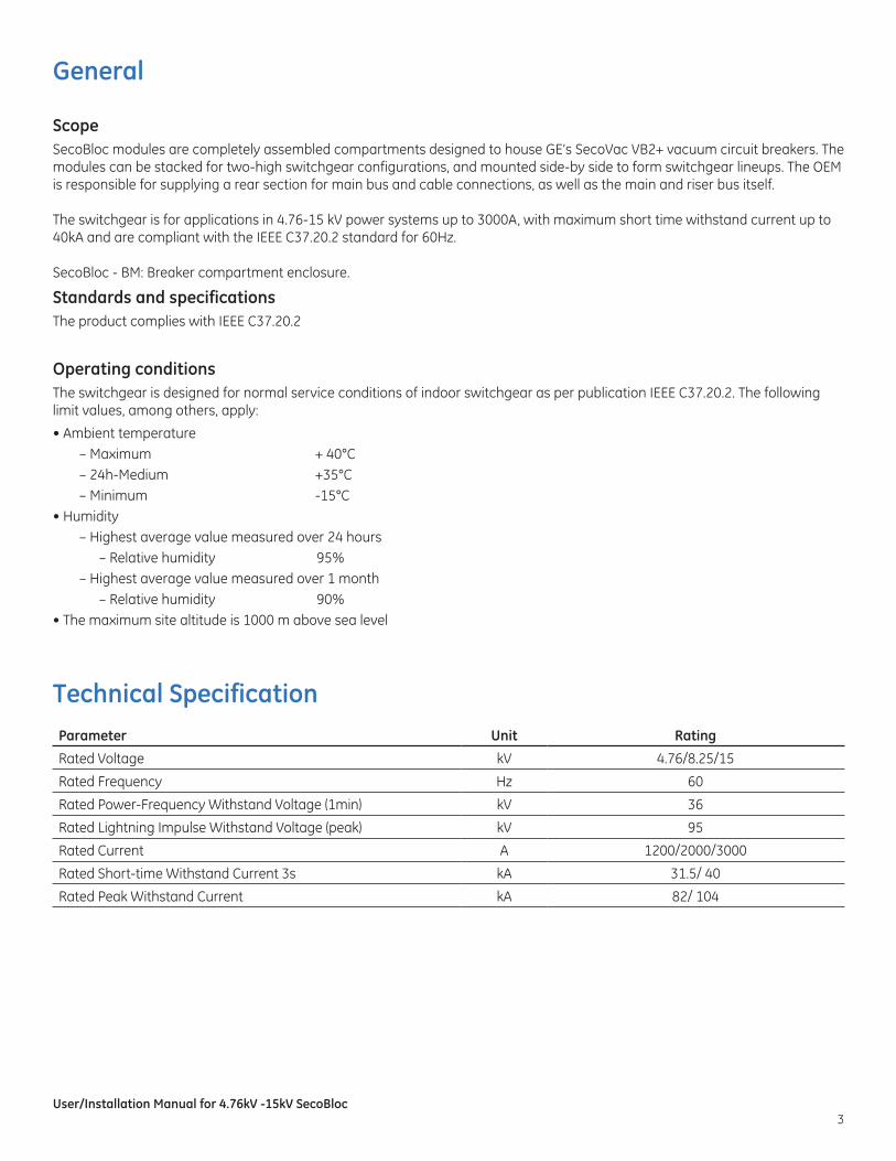
Technical SpecificationParameter Unit Rating
Rated Voltage kV 4.76/8.25/15
Rated Frequency Hz 60
Rated Power-Frequency Withstand Voltage (1min) kV 36
Rated Lightning Impulse Withstand Voltage (peak) kV 95
Rated Current A 1200/2000/3000
Rated Short-time Withstand Current(3s( kA 31.5/ 40
Rated Peak Withstand Current kA 82/ 104
User/Installation Manual for 4.76kV -15kV SecoBloc4
Basic Structure SecoBloc modules are designed for use in constructing MV switchgear arrangements and applications. Each unit of SecoBloc consists of circuit breaker compartment with integrated LV compartment.
FeaturesHigh quality steel sheets of 11 gauge (3 mm) thickness are used for the enclosure. Primary disconnects are supported by high-dielectric epoxy bushings, designed to mount ring-type current transformers. Front compartment doors are supplied as standard.
Compartment door can be used for mounting LV equipment. Refer dimensional drawings for space allowance.
The grounded internal barriers provide dead-front access to the circuit breaker when the busbars are energized. Doors and cover plates are treated against corrosion and then coated with high quality paint. The finishing coat is ANSI 61 grey color.
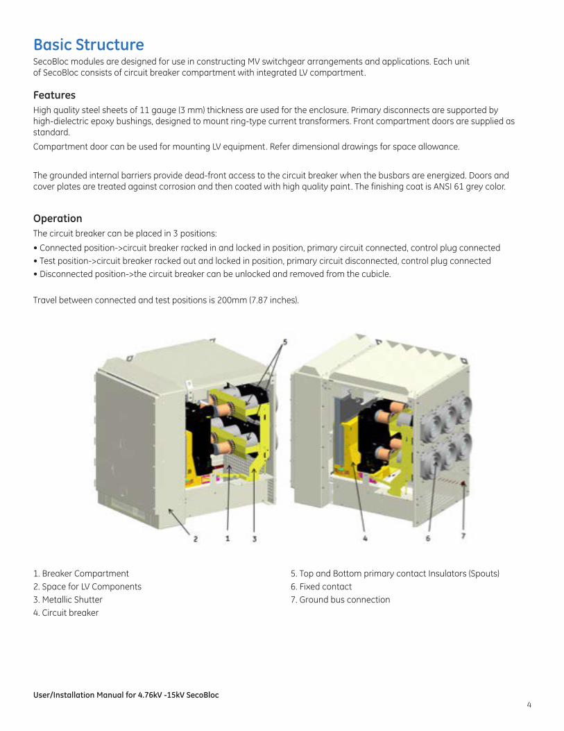
OperationThe circuit breaker can be placed in 3 positions:
• Connected position->circuit breaker racked in and locked in position, primary circuit connected, control plug connected• Test position->circuit breaker racked out and locked in position, primary circuit disconnected, control plug connected• Disconnected position->the circuit breaker can be unlocked and removed from the cubicle.
Travel between connected and test positions is 200mm (7.87 inches).
1. Breaker Compartment2. Space for LV Components3. Metallic Shutter4. Circuit breaker
5. Top and Bottom primary contact Insulators (Spouts)6. Fixed contact 7. Ground bus connection
User/Installation Manual for 4.76kV -15kV SecoBloc5
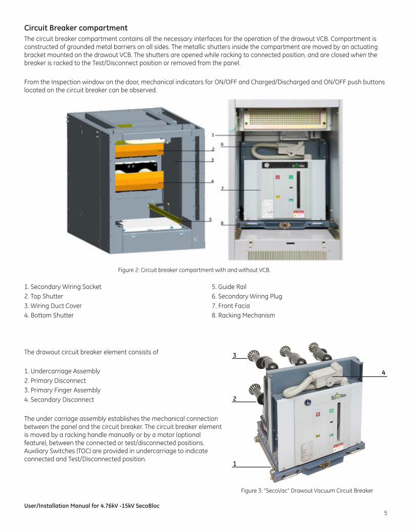
Circuit Breaker compartmentThe circuit breaker compartment contains all the necessary interfaces for the operation of the drawout VCB. Compartment is constructed of grounded metal barriers on all sides. The metallic shutters inside the compartment are moved by an actuating bracket mounted on the drawout VCB. The shutters are opened while racking to connected position, and are closed when the breaker is racked to the Test/Disconnect position or removed from the panel.
From the Inspection window on the door, mechanical indicators for ON/OFF and Charged/Discharged and ON/OFF push buttons located on the circuit breaker can be observed.
Figure 2: Circuit breaker compartment with and without VCB.
1. Secondary Wiring Socket2. Top Shutter3. Wiring Duct Cover4. Bottom Shutter
5. Guide Rail6. Secondary Wiring Plug7. Front Facia8. Racking Mechanism
The drawout circuit breaker element consists of
1. Undercarriage Assembly2. Primary Disconnect3. Primary Finger Assembly4. Secondary Disconnect
The under carriage assembly establishes the mechanical connection between the panel and the circuit breaker. The circuit breaker element is moved by a racking handle manually or by a motor (optional feature), between the connected or test/disconnected positions. Auxiliary Switches (TOC) are provided in undercarriage to indicate connected and Test/Disconnected position.
Figure 3: “SecoVac” Drawout Vacuum Circuit Breaker
2
4
3
1
User/Installation Manual for 4.76kV -15kV SecoBloc6
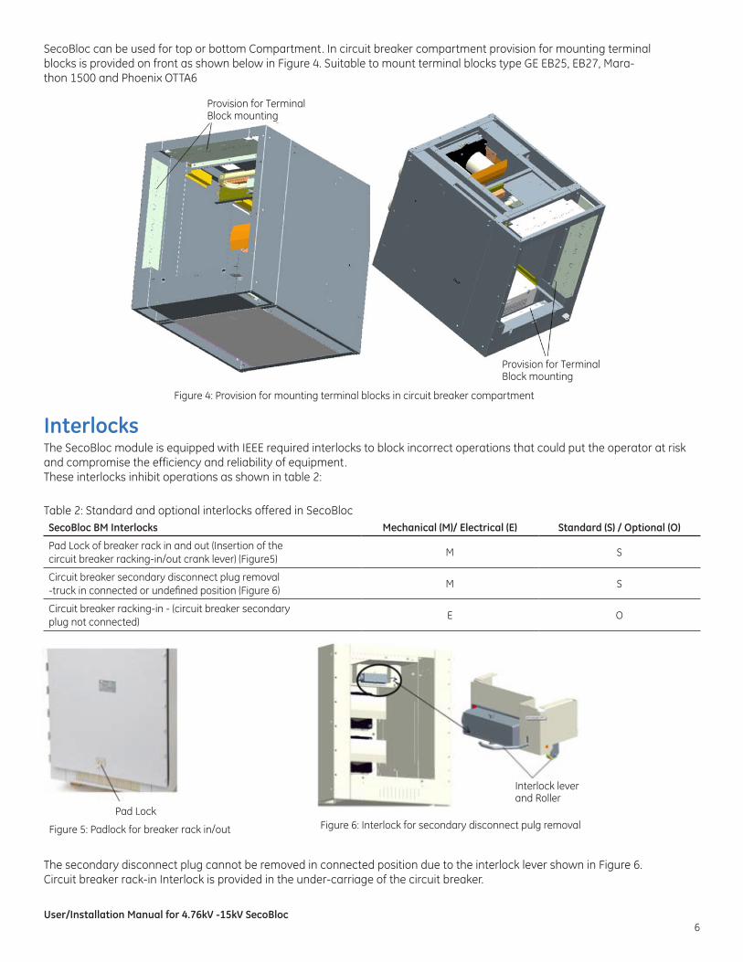
SecoBloc can be used for top or bottom Compartment. In circuit breaker compartment provision for mounting terminal blocks is provided on front as shown below in Figure 4. Suitable to mount terminal blocks type GE EB25, EB27, Mara-thon 1500 and Phoenix OTTA6
Figure 4: Provision for mounting terminal blocks in circuit breaker compartment
Interlocks The SecoBloc module is equipped with IEEE required interlocks to block incorrect operations that could put the operator at risk and compromise the efficiency and reliability of equipment.These interlocks inhibit operations as shown in table 2:
Table 2: Standard and optional interlocks offered in SecoBloc
The secondary disconnect plug cannot be removed in connected position due to the interlock lever shown in Figure 6.Circuit breaker rack-in Interlock is provided in the under-carriage of the circuit breaker.
SecoBloc BM Interlocks Mechanical (M)/ Electrical (E) Standard (S) / Optional (O)
Pad Lock of breaker rack in and out (Insertion of the circuit breaker racking-in/out crank lever) (Figure5)
M S
Circuit breaker secondary disconnect plug removal -truck in connected or undefined position (Figure 6)
M S
Circuit breaker racking-in - (circuit breaker secondary plug not connected)
E O
Figure 5: Padlock for breaker rack in/out Figure 6: Interlock for secondary disconnect pulg removal
Provision for Terminal Block mounting
Provision for Terminal Block mounting
Pad Lock
Interlock lever and Roller
User/Installation Manual for 4.76kV -15kV SecoBloc7
Transport and Storage
Condition on deliveryAt the time of shipment, the factory- assembled SecoBloc module and drawout circuit breaker element are packed separately. The SecoBloc modules and breakers are verified in the factory for accuracy as per order requirement, and compliance with routine testing as per IEEE C37.20.2.
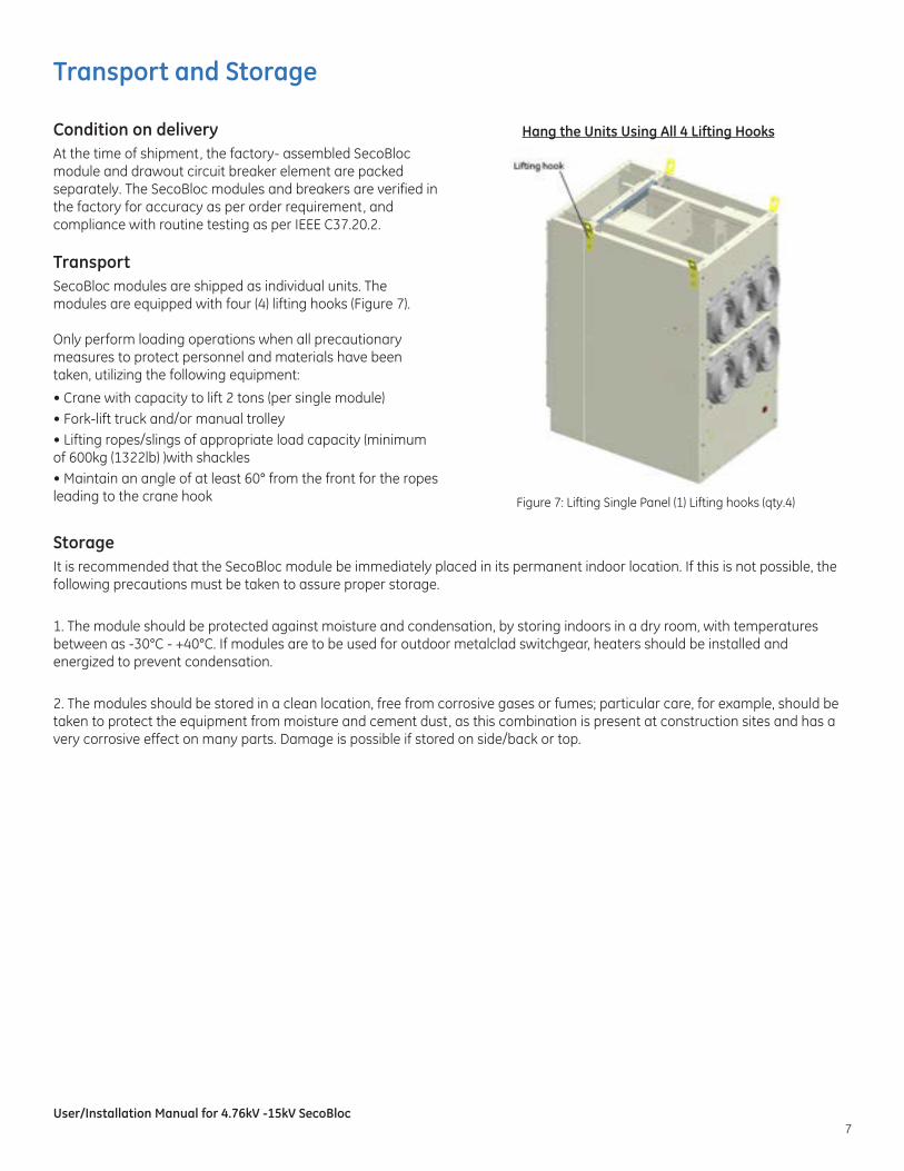
Transport SecoBloc modules are shipped as individual units. The modules are equipped with four (4) lifting hooks (Figure 7).
Only perform loading operations when all precautionary measures to protect personnel and materials have been taken, utilizing the following equipment:
• Crane with capacity to lift 2 tons (per single module)• Fork-lift truck and/or manual trolley• Lifting ropes/slings of appropriate load capacity (minimum of 600kg (1322lb) )with shackles• Maintain an angle of at least 60° from the front for the ropes leading to the crane hook
Storage It is recommended that the SecoBloc module be immediately placed in its permanent indoor location. If this is not possible, the following precautions must be taken to assure proper storage.
1. The module should be protected against moisture and condensation, by storing indoors in a dry room, with temperatures between as -30°C - +40°C. If modules are to be used for outdoor metalclad switchgear, heaters should be installed and energized to prevent condensation.
2. The modules should be stored in a clean location, free from corrosive gases or fumes; particular care, for example, should be taken to protect the equipment from moisture and cement dust, as this combination is present at construction sites and has a very corrosive effect on many parts. Damage is possible if stored on side/back or top.
Figure 7: Lifting Single Panel (1) Lifting hooks (qty.4)
Hang the Units Using All 4 Lifting Hooks
User/Installation Manual for 4.76kV -15kV SecoBloc8
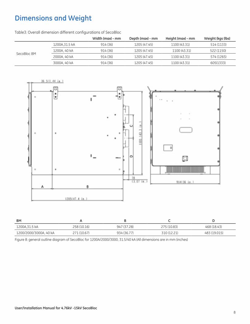
Dimensions and Weight
Width (max) - mm Depth (max) - mm Height (max) - mm Weight (kgs (lbs)
SecoBloc BM
1200A,31.5 kA 914 (36) 1205 (47.45) 1100 (43.31) 514 (1133)
1200A, 40 kA 914 (36) 1205 (47.45) 1100 (43.31) 522 (1150)
2000A, 40 kA 914 (36) 1205 (47.45) 1100 (43.31) 574 (1265)
3000A, 40 kA 914 (36) 1205 (47.45) 1100 (43.31) 605(1333)
BM A B C D
1200A,31.5 kA 258 (10.16) 947 (37.28) 275 (10.83) 468 (18.43)
1200/2000/3000A, 40 kA 271 (10.67) 934 (36.77) 310 (12.21) 483 (19.015)
Table3: Overall dimension different configurations of SecoBloc
Figure 8: general outline diagram of SecoBloc for 1200A/2000/3000, 31.5/40 kA (All dimensions are in mm (inches)
A B
CD
User/Installation Manual for 4.76kV -15kV SecoBloc9
Circuit Breaker Installation and Removal
Preparations: Before start up, the following work should be completed.
a. Visually inspect the overall condition of the module for damage.b. Ensure there are no unnecessary materials or tools inside of the compartment.c. Wipe the compartment body and the insulation parts, clean with a soft clothd. Inspect and test the VB2+ circuit breaker per Instruction Book DEH-50001
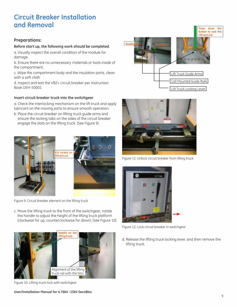
Insert circuit breaker truck into the switchgear
a. Check the interlocking mechanism on the lift truck and apply lubricant on the moving parts to ensure smooth operation.b. Place the circuit breaker on lifting truck guide arms and
ensure the locking tabs on the sides of the circuit breaker engage the slots on the lifting truck. (See Figure 9).
c. Move the lifting truck to the front of the switchgear; rotate the handle to adjust the height of the lifting truck platform (clockwise for up, counterclockwise for down), (See Figure 10).
Figure 9: Circuit breaker element on the lifting truck
Alignment of the lifting truck rail with the bloc.
d. Release the lifting truck locking lever, and then remove the lifting truck.
Figure 10: Lifting truck lock with switchgear
Figure 11: Unlock circuit breaker from lifting truck
Figure 12: Lock circuit breaker in switchgear
Lift Truck Guide Arms
Cell Mounted Guide Rails
Lift Truck Locking Lever
User/Installation Manual for 4.76kV -15kV SecoBloc10
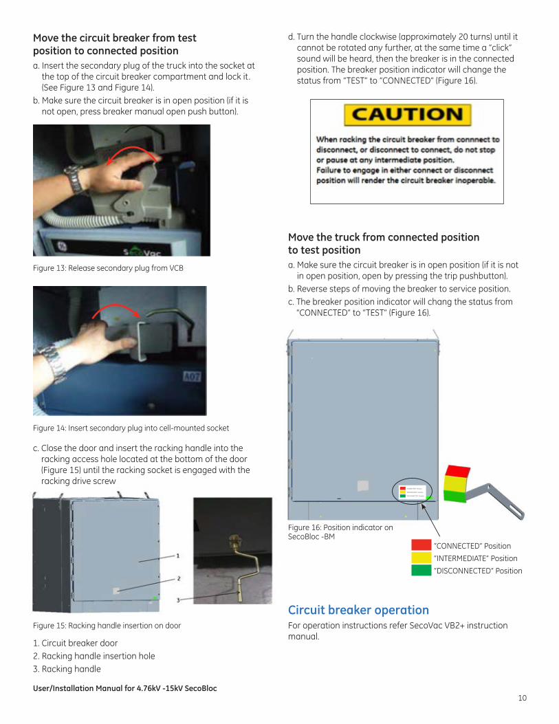
Move the circuit breaker from test position to connected positiona. Insert the secondary plug of the truck into the socket at
the top of the circuit breaker compartment and lock it . (See Figure 13 and Figure 14).
b. Make sure the circuit breaker is in open position (if it is not open, press breaker manual open push button).
c. Close the door and insert the racking handle into the racking access hole located at the bottom of the door (Figure 15) until the racking socket is engaged with the racking drive screw
Figure 13: Release secondary plug from VCB
Figure 14: Insert secondary plug into cell-mounted socket
Figure 15: Racking handle insertion on door
d. Turn the handle clockwise (approximately 20 turns) until it cannot be rotated any further, at the same time a “click” sound will be heard, then the breaker is in the connected position. The breaker position indicator will change the status from “TEST” to “CONNECTED” (Figure 16).
Move the truck from connected position to test positiona. Make sure the circuit breaker is in open position (if it is not
in open position, open by pressing the trip pushbutton).b. Reverse steps of moving the breaker to service position. c. The breaker position indicator will chang the status from
“CONNECTED” to “TEST” (Figure 16).
Circuit breaker operationFor operation instructions refer SecoVac VB2+ instruction manual.
Figure 16: Position indicator on SecoBloc -BM
“CONNECTED” Position
“INTERMEDIATE” Position
“DISCONNECTED” Position
“CONNECTED” Position
“INTERMEDIATE” Position
“DISCONNECTED” Position
1. Circuit breaker door2. Racking handle insertion hole3. Racking handle
User/Installation Manual for 4.76kV -15kV SecoBloc11
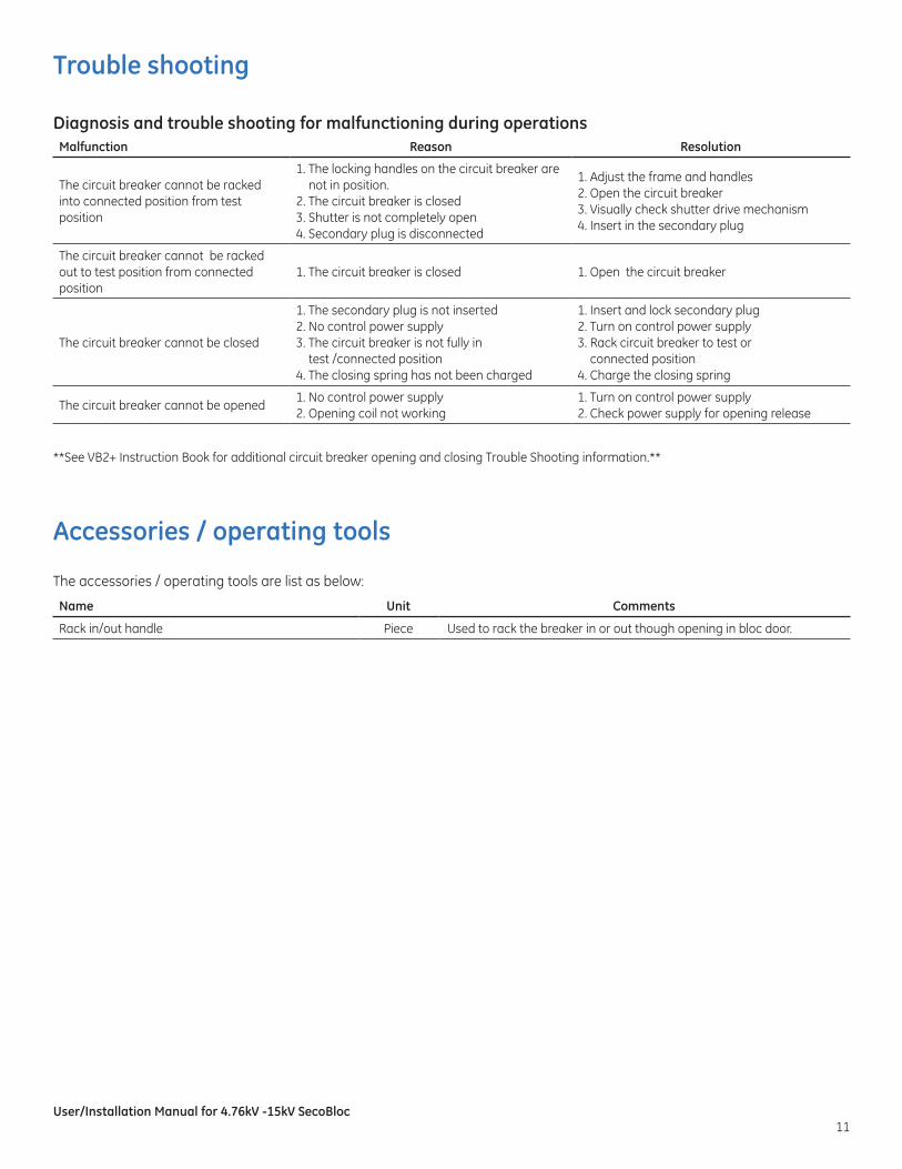
Trouble shooting
Diagnosis and trouble shooting for malfunctioning during operations
Accessories / operating tools
The accessories / operating tools are list as below:
**See VB2+ Instruction Book for additional circuit breaker opening and closing Trouble Shooting information.**
Malfunction Reason Resolution
The circuit breaker cannot be racked into connected position from test position
1. The locking handles on the circuit breaker are not in position.
2. The circuit breaker is closed 3. Shutter is not completely open4. Secondary plug is disconnected
1. Adjust the frame and handles2. Open the circuit breaker 3. Visually check shutter drive mechanism 4. Insert in the secondary plug
The circuit breaker cannot be racked out to test position from connected position
1. The circuit breaker is closed 1. Open the circuit breaker
The circuit breaker cannot be closed
1. The secondary plug is not inserted2. No control power supply 3. The circuit breaker is not fully in
test /connected position4. The closing spring has not been charged
1. Insert and lock secondary plug2. Turn on control power supply3. Rack circuit breaker to test or
connected position4. Charge the closing spring
The circuit breaker cannot be opened1. No control power supply2. Opening coil not working
1. Turn on control power supply2. Check power supply for opening release
Name Unit Comments
Rack in/out handle Piece Used to rack the breaker in or out though opening in bloc door.
User/Installation Manual for 4.76kV -15kV SecoBloc12
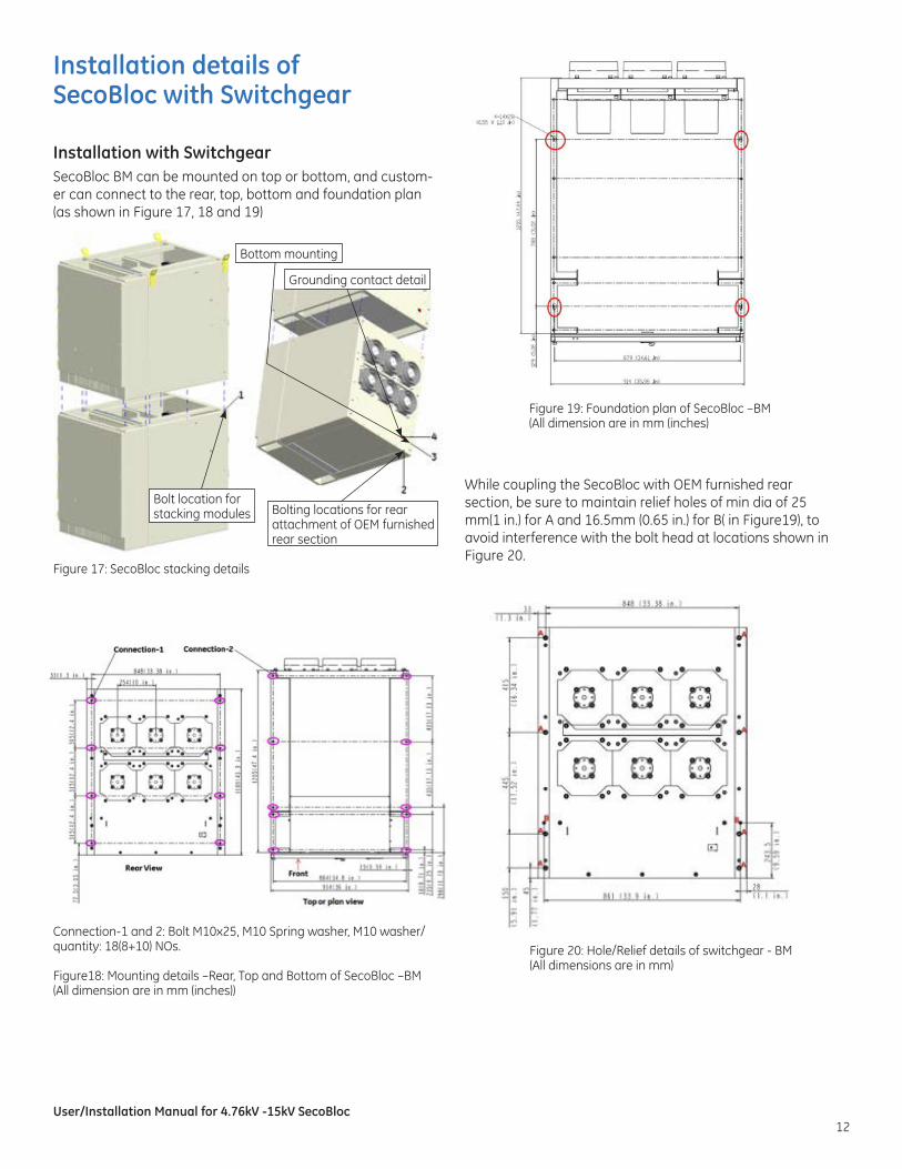
Installation details of SecoBloc with Switchgear
Installation with SwitchgearSecoBloc BM can be mounted on top or bottom, and custom-er can connect to the rear, top, bottom and foundation plan (as shown in Figure 17, 18 and 19)
While coupling the SecoBloc with OEM furnished rear section, be sure to maintain relief holes of min dia of 25 mm(1 in.) for A and 16.5mm (0.65 in.) for B( in Figure19), to avoid interference with the bolt head at locations shown in Figure 20.
Figure 17: SecoBloc stacking details
Connection-1 and 2: Bolt M10x25, M10 Spring washer, M10 washer/quantity: 18(8+10) NOs.
Figure18: Mounting details –Rear, Top and Bottom of SecoBloc –BM (All dimension are in mm (inches))
Figure 19: Foundation plan of SecoBloc –BM (All dimension are in mm (inches)
Bolt location for stacking modules
Bottom mounting
Grounding contact detail
Bolting locations for rear attachment of OEM furnished rear section
Figure 20: Hole/Relief details of switchgear - BM (All dimensions are in mm)
User/Installation Manual for 4.76kV -15kV SecoBloc13
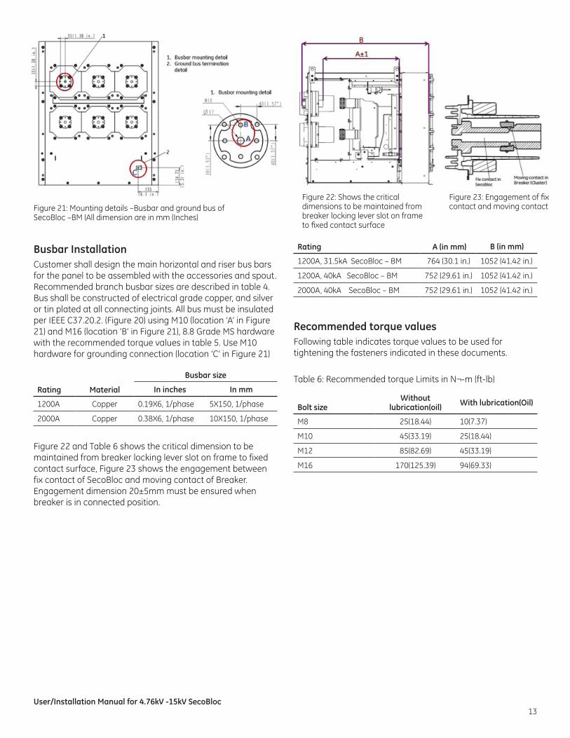
Figure 21: Mounting details –Busbar and ground bus of SecoBloc –BM (All dimension are in mm (Inches)
Busbar InstallationCustomer shall design the main horizontal and riser bus bars for the panel to be assembled with the accessories and spout. Recommended branch busbar sizes are described in table 4. Bus shall be constructed of electrical grade copper, and silver or tin plated at all connecting joints. All bus must be insulated per IEEE C37.20.2. (Figure 20) using M10 (location ‘A’ in Figure 21) and M16 (location ‘B’ in Figure 21), 8.8 Grade MS hardware with the recommended torque values in table 5. Use M10 hardware for grounding connection (location ‘C’ in Figure 21)
Figure 22 and Table 6 shows the critical dimension to be maintained from breaker locking lever slot on frame to fixed contact surface, Figure 23 shows the engagement between fix contact of SecoBloc and moving contact of Breaker. Engagement dimension 20±5mm must be ensured when breaker is in connected position.
Recommended torque valuesFollowing table indicates torque values to be used for tightening the fasteners indicated in these documents.
Table 6: Recommended torque Limits in N¬-m (ft-lb)Rating Material
Busbar size
In inches In mm
1200A Copper 0.19X6, 1/phase 5X150, 1/phase
2000A Copper 0.38X6, 1/phase 10X150, 1/phase
Rating A (in mm) B (in mm)
1200A, 31.5kA SecoBloc – BM 764 (30.1 in.) 1052 (41.42 in.)
1200A, 40kA SecoBloc – BM 752 (29.61 in.) 1052 (41.42 in.)
2000A, 40kA SecoBloc – BM 752 (29.61 in.) 1052 (41.42 in.)
Bolt sizeWithout
lubrication(oil) With lubrication(Oil)
M8 25(18.44) 10(7.37)
M10 45(33.19) 25(18.44)
M12 85(82.69) 45(33.19)
M16 170(125.39) 94(69.33)
Figure 22: Shows the critical dimensions to be maintained from breaker locking lever slot on frame to fixed contact surface
Figure 23: Engagement of fix contact and moving contact
User/Installation Manual for 4.76kV -15kV SecoBloc14
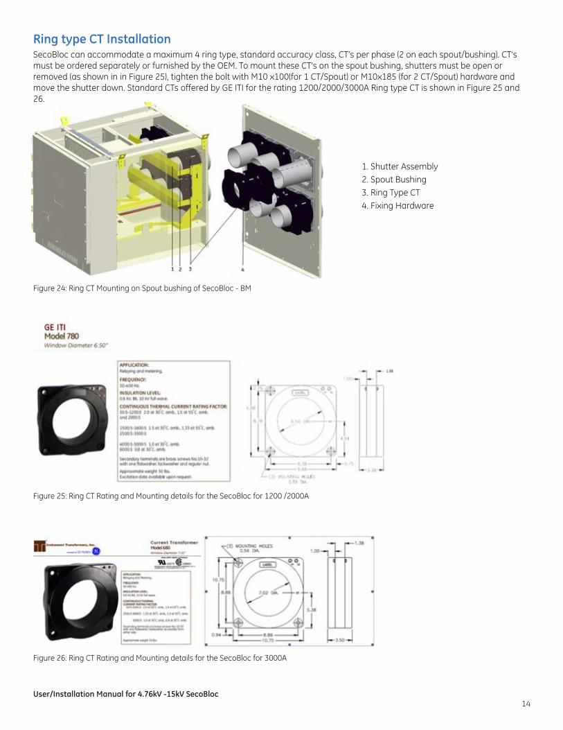
Ring type CT InstallationSecoBloc can accommodate a maximum 4 ring type, standard accuracy class, CT’s per phase (2 on each spout/bushing). CT’s must be ordered separately or furnished by the OEM. To mount these CT’s on the spout bushing, shutters must be open or removed (as shown in in Figure 25), tighten the bolt with M10 x100(for 1 CT/Spout) or M10x185 (for 2 CT/Spout) hardware and move the shutter down. Standard CTs offered by GE ITI for the rating 1200/2000/3000A Ring type CT is shown in Figure 25 and 26.
Figure 24: Ring CT Mounting on Spout bushing of SecoBloc - BM
Figure 26: Ring CT Rating and Mounting details for the SecoBloc for 3000A
Figure 25: Ring CT Rating and Mounting details for the SecoBloc for 1200 /2000A
1. Shutter Assembly2. Spout Bushing3. Ring Type CT4. Fixing Hardware

GE Industrial Solutions 41 Woodford Avenue Plainville, CT 06062 1-800-431-7867 www.geindustrial.com
* Trademark of General Electric Company
These instructions do not purport to cover all details or variations in equipment nor, to provide contingency to be met in connection with installation, operation, or maintenance. Should further information be desired, or should particular problems arise which are not
covered sufficiently for the purchaser’s purposes, the matter should be referred to GE.
12.14 DEH-50002