Embed Size (px)
Citation preview

User Guide

Table of Contents
Introduction 3
Key Features 3
In the Box 4
System Requirements 5Macintosh 5Windows 5iOS 5
Hardware Connections 6Front Panel 6Rear Panel 7
Getting Started 8Install iConfig and Upgrade Your PlayAUDIO12 Firmware 8
PlayAUDIO12 Failover Redundancy 9How the PlayAUDIO12's Failover SystemWorks 9How to Arm the PlayAUDIO12 for Automatic Failover 9How to Test Automatic Failover 11How to Configure the PlayAUDIO12 for Manual Failover 11
Controls 12Interactive Touch Panel Display 12Using the Touch Panel 12Scene 12Volume/Gain 13Outputs 13Phones 14

PlayAUDIO12User Guide v1.0
IntroductionThank you for purchasing the PlayAUDIO12, a unique audio/MIDI interface and integrated failover systemthat has been designed to provide compact and easy-to-operate failover protection for the live per-formance arena.
Your PlayAUDIO12 offers superb sound quality and flexible MIDI capabilities, and integrates performanceand peace-of-mind by providing fail-safe control and playback of backing tracks, virtual instruments, andMIDI devices in a live setting.
Key FeaturesKey features of the PlayAUDIO12 include:
l (10) 1/4” TRS balanced audio outputs for low noise connections on any stage. (All outputs are +48vphantom power resistant.)
l (1) 1/4” TRS stereo headphone output for convenient headphonemonitoring.
l (2) USB-B ports for connection of up to 2 computers simultaneously.
l Studio sound quality for the live arena: up to 24-bit/96kHzDA conversion.
l Automatic andmanual computer switchingmodes, for lightning-fast switching between connectedcomputers.
l USBMIDI host port, offering up to 8 ports of USBMIDI for class-compliant controllers and/or mod-ules.
l Ethernet MIDI for rugged, long-distanceMIDI connections.
l Simple, manual control over PlayAUDIO12's key features from the front panel.
l Control In footswitch input that allows for manual computer switching and/or user-assignable con-trols.
l Control Out connection for slaving additional PlayAUDIO12 units.
l USB Audio 2.0 and USBMIDI 1.0 class-compliant.
3
PlayAUDIO12User Guide v1.0
In the Boxl The PlayAUDIO12 Audio/MIDI interface.
l (1) USB-A to USB-B cable for connecting aMacOS or Windows computer to your PlayAUDIO12.
l The PlayAUDIO12 power supply.
4

PlayAUDIO12User Guide v1.0
System RequirementsMacintosh
l MacOSX 10.8 or later
l (1) free USB port
Windowsl Windows 7 or later
l (1) free USB port
iOSl iOS 8.0 or later with Lightning connector
l Apple Camera Connection Kit
l CoreMIDI-compatible application
Visit http://www.iconnectivity.com/support-system for themost up-to-date compatibility requirements, asthese are subject to change.
Product features are subject to change. Apple logo, Macintosh, OS X, Mac, iPad, iPhone, and iPod touchare trademarks of Apple Inc., registered in the U.S. and other countries. iConnectivity, iConnectMIDI, iCon-nectAUDIO, ConnectAUDIO, mio, PlayAUDIO, and Audio passThru are trademarks of iKingdomCorp.Copyright (c) iKingdomCorp. 2017
5
PlayAUDIO12User Guide v1.0
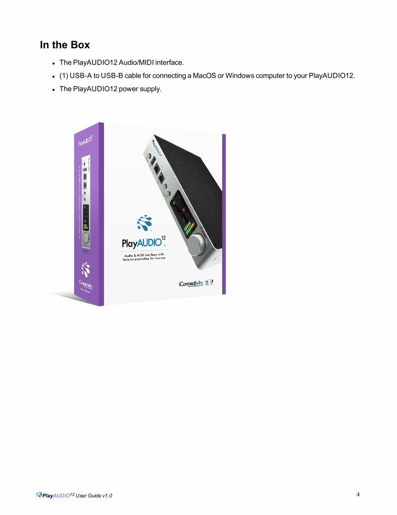
Hardware ConnectionsFront Panel
l Stereo Headphone Jack
l USB-A Host MIDI port. This USB 2.0 jack supports up to eight 16-channel MIDI Ports from eight USBMIDI class-compliant devices.
l USB-B Device Ports. Use these ports to connect up to two computers or iOS devices simultaneously.
l Control In Jack. Use this TRS input to attach a footswitch for manual failover switching.
l Control Out Jack. Use this TRS output to chain additional PlayAUDIO12 units.
l Interactive touch panel display. The PlayAUDIO12's touch panel makes it easy to set output levels/-gain and to create audio/MIDIScenes that can be recalled later.
l Rotary Control Dial. For manual adjustment of volume/gain levels, saving settings tomemory, andpowering the unit ON andOFF.
6

PlayAUDIO12User Guide v1.0
Rear Panel
l Power Jack.Connect the included PlayAUDIO12 power supply here.
l Balanced Analog Outputs. The PlayAUDIO12's 10 analog outputs provide low noise, phantompower-resistant connections that boast up to 24-bit/96kHzDA conversion.
l MIDI Ethernet Port.Use this port for long-distanceMIDI connections.
7

PlayAUDIO12User Guide v1.0
Getting StartedInstall iConfig and Upgrade Your PlayAUDIO12 FirmwareBefore you begin using your PlayAUDIO12, we recommend that you upgrade your unit's firmware to thelatest version using iConnectivity's iConfig application. Follow these steps to install the iConfig softwareand perform the firmware upgrade:
1. Download the latest version (4.2.6) of the iConfig software installer.
i. Go to https://www.iconnectivity.com/software/iconfig
ii. Follow the instructions for downloading the iConfig software installer specific to your computer.
2. Connect your computer to the PlayAUDIO12. For Mac andWindows computers, use the USB-A to USB-B cable that came in the box to connect your computer to the USB Device Port 1 on thefront panel of your PlayAUDIO12 unit.
3. Launch the iConnectivity iConfig installer file.Connect your computer to the internet. Then,with your computer connected to thePlayAUDIO12, double-click the iConnectivity iConfiginstaller.
4. Accept the firmware upgrade if your unit detects that newer firmware is available. The iCon-fig software will prompt you to upgrade if a newer firmware version is available. Verify that yourdevice is connected to USB Device Port 1 and clickYes to continue with the upgrade. AnUpgradeComplete prompt will appear when the process completes, at which point iConfig'sDevice Info pagewill refresh with your PlayAUDIO12's device statistics.
Figure 1: Updating the PlayAUDIO12 firmware
8

PlayAUDIO12User Guide v1.0
PlayAUDIO12 Failover RedundancyHow the PlayAUDIO12's Failover System WorksYour PlayAUDIO12 unit comes equipped with two discrete failover mechanisms: Automatic Failover andManual Failover. This failover redundancy is designed to ensure that your backup system can always beengaged instantly and seamlessly, whether via auto-detection or throughmanual switching. Taking advant-age of both of these failover mechanisms is recommended for all live performance scenarios.
Automatic Failover uses a test tone sent from your DAW to establish an audio-recognition sync lockbetween your primary playback device and your PlayAUDIO12 interface on a dedicated internal audiochannel. Once armed, the PlayAUDIO12 instantly switches to your secondary device if any break in thetest tone signal is detected, providing a seamless failover to your backup systemwithout audio or MIDIinterruption.
Manual Failover allows you to connect a footswitch to the PlayAUDIO12'sControl In jack and instantlyswitch between your primary and backup computers on the fly, enabling you tomanuallymove to yourbackup system in the event of an emergency, or if you anticipate an issue with your primary system beforeit actually occurs.
How to Arm the PlayAUDIO12 for Automatic FailoverA test tone generator is required to arm the PlayAUDIO12 for Automatic Failover. If a test tone generatorisn't included with your Digital AudioWorkstation, download and install iConnectivity'sLifeSine test toneplugin from https://www.iconnectivity.com/downloads/.
Follow the steps below to arm the PlayAUDIO12 for automatic failover and test your unit's failover cap-ability:
1. Connect Computer A (your primary playback device) to USB Device Port 1.
2. Connect Computer B (your failover playback device) to USB Device Port 2.
3. Verify that the PlayAUDIO12 is set toScene A (green LED indicator). If the LED indicator light is red(indicating that Scene B is active), touch theScene LED once to toggle the button state andmakeScene A the active scene.
Figure 2: Scene A must be the active Scene on the PlayAUDIO12 to arm the unit for Automatic Failover
9

PlayAUDIO12User Guide v1.0
4. On both computers (Computer A and Computer B), open your Digital AudioWorkstation and loadyour playback project.
5. On Computer A (your primary playback device), instantiate your test tone plugin on a free track andassign it to the PlayAUDIO12's audio output 13 (Control Tone). When your PlayAUDIO12 unitdetects the test tone, the greenScene A LED light will blink, indicating that the PlayAUDIO12 isarmed for automatic failover.
Figure 3: Sending the test tone to the PlayAUDIO12's audio output 13 from Ableton Live 9
Figure 4: The Scene A LED indicator will blink steadily when the unit is armed for automatic failover
10

PlayAUDIO12User Guide v1.0
6. Connect aMIDI external controller to the USB host port. Ensure that both DAWs are configured sothat playback can be triggered on both DAWs simultaneously.
7. With the unit armed, use the attachedMIDI external controller to trigger simultaneous playback onComputer A and Computer B.
How to Test Automatic Failover1. Ensure that the unit is armed and playback has been triggered on both computers. To force failover
fromComputer A to Computer B, remove the cable fromUSB Device Port 1. The PlayAUDIO12willinstantly switch over to Computer B as Audio andMIDI playback continues uninterrupted. The Sceneindicator LED will change to red, indicating that Scene B is now the active scene.
How to Configure the PlayAUDIO12 for Manual Failover1. Connect a 2-button TRS footswitch to theControl In jack on the PlayAUDIO12's front panel.
2. With the footswitch connected, engage either footswitch channel to activate failover to the opposingScene. TheScene LED on the touch panel will toggle to indicate the Scene that is active. (Addi-tionally, note that pressing theScene button on the touch panel also allows you to toggle the activeScene.)
Figure 5: .Scene A active (left). Scene B active (right).
11

PlayAUDIO12User Guide v1.0
ControlsInteractive Touch Panel Display
The PlayAUDIO12's Interactive Touch Panel Display is a capacitive touch panel that provides the fol-lowing features:
l Eight touch zones for intuitive control over Scene selection, level adjustment to the PlayAUDIO12’sanalog outputs, and headphone levels.
l Dual 8-stage LED meters and independent meteringmodes for select functions.
l A Rotary Control Dial for dialing in gain/level adjustments. The Rotary Control Dial also performsauxiliary functions, such as:
o Committing Settings to Memory: Press the dial once to commit the current settings tomemory.
o Powering down the unit: Press and hold the Rotary Control Dial until bothmeter columnsshow red and yellow LED indicators at the top of the display. Then, release the dial to powerthe unit OFF. From theOFF state, press the dial once to power the unit backON.
Note: The Rotary Control Dial is continuous and canmake fine or coarse adjustments depending on howquickly you rotate the dial. Fine adjustments are recommended if there is a risk of signal overload.
Using the Touch PanelPressing any of the PlayAUDIO12 touch zones toggles the zone to the next available state. The color ofthe LED status indicator corresponds to the color of the display text and indicates the active function for thezone:
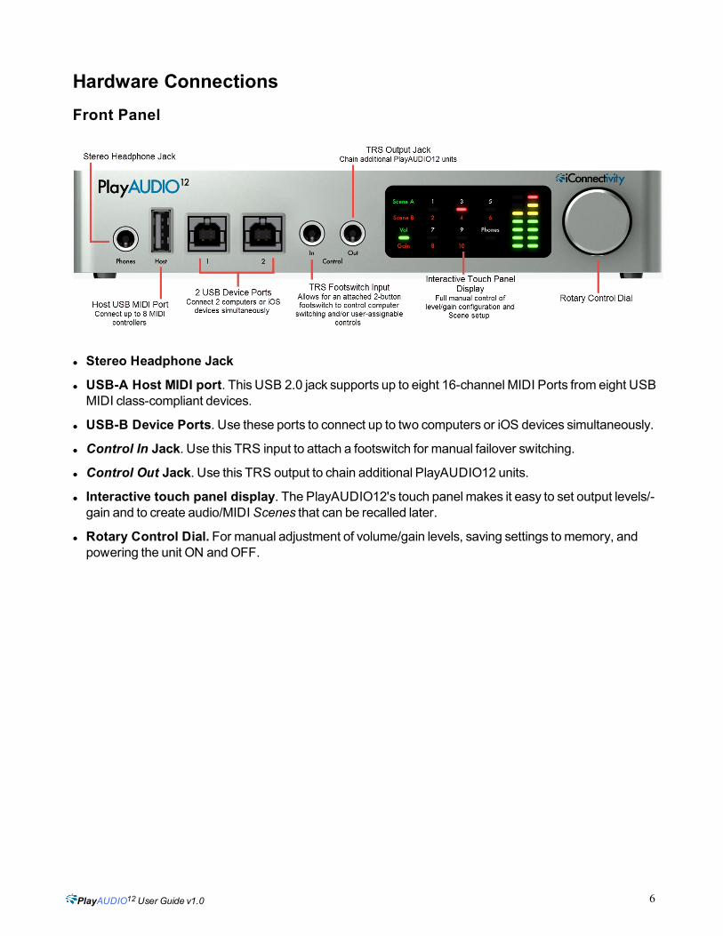
Scene
Press once to toggle between Scene A and Scene B.
12
PlayAUDIO12User Guide v1.0
Figure 6: Press once to toggle between Scenes.
Volume/Gain
Press once to toggle between Volume displaymode andGain displaymode.
Figure 7: Press once to toggle between Volume display and Gain display modes.
Outputs
Output zones have three states and will toggle successively in this order:
l Odd-numbered output
l Even-numbered output
l Stereo output pair
13

PlayAUDIO12User Guide v1.0
Figure 8: Pressing the touch zone successively will select (in this example) Output 1, Output 2, or Stereo Output 1/2
Phones
Press once to toggle between Volumemode andGainmode.
Figure 9: Press once to toggle Phones to Gain Setmode.
14


![Rachmaninov 3rd Piano Concerto [First Movement] · PDF file53-g e5 = 5 !5 = 5 5 5 5 5 4 5 5 =5 5 = 5e5 5 5 5 5 5 5 5e5 5 5!55 5 5 5 5 5e5 5 5 5 5 5 5! 5 $3e55 5 5: 5 5 5 55 5e 55 5](https://img.pdfslide.us/doc/110x75/5a78944a7f8b9a1f128d15db/rachmaninov-3rd-piano-concerto-first-movement-53-g-e5-5-5-5-5-5-5-5-4-5.jpg)