Embed Size (px)
Citation preview
User’sManual
YTA70Temperature Transmitter
IM 01C50C03-01E
IM 01C50C03-01E5th Edition
iIM 1C50T1-01E
CONTENTS
CONTENTS
1. MODEL AND SUFFIX CODES .....................................................1
2. WARRANTY...................................................................................1
3. HANDLING PRECAUTIONS .........................................................2
4. STANDARD SPECIFICATIONS.....................................................2
5. BLOCK DIAGRAM ........................................................................4
6. WIRING ..........................................................................................4
7. SAFETY APPROVALS ..................................................................57.1 CENELEC ATEX(DEMCO) Intrinsically safe model ........... 57.2 FM Intrinsically safe model ................................................. 6
8. HART COMMUNICATION .............................................................78.1 Connection and Requirements ............................................ 78.2 Parameters .......................................................................... 8
REVISION RECORD
FD No. IM 01C50C03 -01E5th Edition: July 2003 (YG)All Rights Reserved, Copyright © 1999, Yokogawa Electric Corporation
IM 01C50C03-01E 1
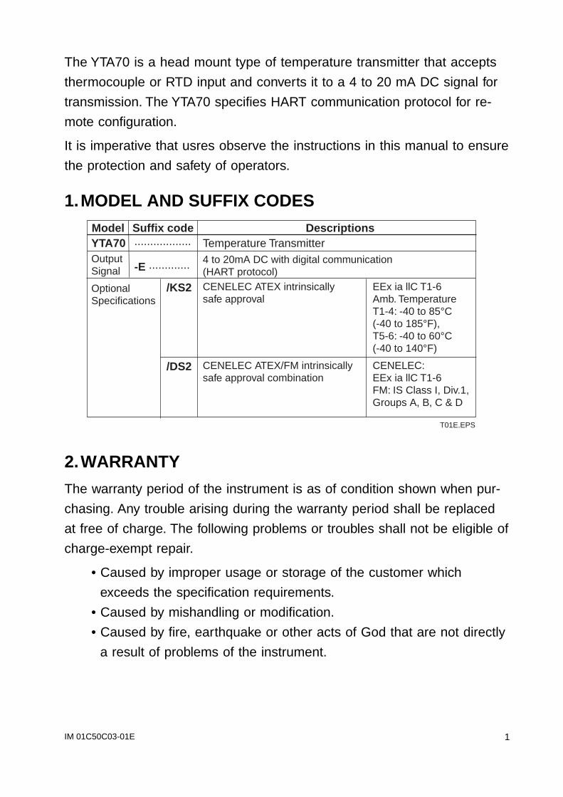
The YTA70 is a head mount type of temperature transmitter that accepts
thermocouple or RTD input and converts it to a 4 to 20 mA DC signal for
transmission. The YTA70 specifies HART communication protocol for re-
mote configuration.
It is imperative that usres observe the instructions in this manual to ensure
the protection and safety of operators.
1.MODEL AND SUFFIX CODES
Temperature Transmitter 4 to 20mA DC with digital communication(HART protocol)
T01E.EPS
Model Suffix code DescriptionsYTA70 ..................
OutputSignal
OptionalSpecifications
-E .............
/KS2 EEx ia llC T1-6Amb. TemperatureT1-4: -40 to 85°C(-40 to 185°F),T5-6: -40 to 60°C(-40 to 140°F)
CENELEC ATEX/FM intrinsicallysafe approval combination
CENELEC:EEx ia llC T1-6FM: IS Class I, Div.1,Groups A, B, C & D
/DS2
CENELEC ATEX intrinsicallysafe approval
2.WARRANTY
The warranty period of the instrument is as of condition shown when pur-
chasing. Any trouble arising during the warranty period shall be replaced
at free of charge. The following problems or troubles shall not be eligible of
charge-exempt repair.
• Caused by improper usage or storage of the customer which
exceeds the specification requirements.
• Caused by mishandling or modification.
• Caused by fire, earthquake or other acts of God that are not directly
a result of problems of the instrument.
IM 01C50C03-01E2
3.HANDLING PRECAUTIONS
(1) Read this manual throughly and carefully before handling the instru-
ments. Observe the instructions.
(2) Store the product in location that meets the following requirements.
• No exposure to rain or water
• No major mechanical vibration or shock
• Humidity and Temperature limitations
• Ordinary conditions(25°C, 65%) is preferable.Otherwise, as of specified in “Standard Specifications.”
(3) Avoid corrosive atmosphere for storage and installation.
(4) For safe installation of the transmitter in hazardous area, the
following must be observed. The module must only be installed by
qualified personnels who are familiar with the national and international
laws, directives, and standards that apply to this area.
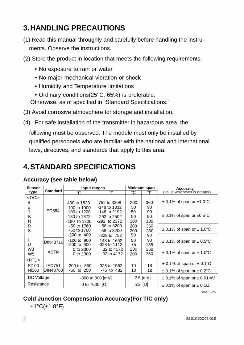
4.STANDARD SPECIFICATIONS
Accuracy (see table below)Sensor
type StandardInput ranges Minimum span Accuracy
<T/C>C C
B 400 to 1820 200 ± 0.1% of span or ±1.0C E
IEC584-100 to 1000 50
J -100 to 1200 50± 0.1% of span or ±0.5C K -180 to 1372 50
N -180 to 1300 100 R -50 to 1760
200 ± 0.1% of span or ± 1.0C S -50 to 1760200
T -200 to 400 50
± 0.1% of span or ± 0.5C L DIN43710 -100 to 900 50 U -200 to 600 75 W3
ASTM 0 to 2300 200
± 0.1% of span or ± 1.0C W5 0 to 2300 200 <RTD> Pt100 -200 to 850 10 ± 0.1% of span or ± 0.1C
Ni100 -60 to 250 10
T02E.EPS
752 to 3308-148 to 1832-148 to 2192-292 to 2502-292 to 2372 -58 to 3200 -58 to 3200 -328 to 752 -148 to 1652 -328 to 1112 32 to 4172 32 to 4172
-328 to 1562 -76 to 482
F F (value whichever is greater)
3609090901803603609090
135360360
18± 0.1% of span or ± 0.2C
DC Voltage
Resistance -800 to 800 [mV]
0 to 7000 [Ω]
2.5 [mV]
25 [Ω]
± 0.1% of span or ± 0.01mV
± 0.1% of span or ± 0.1Ω
18DIN43760IEC751
Cold Junction Compensation Accuracy(For T/C only)±1°C(±1.8°F)
IM 01C50C03-01E 3
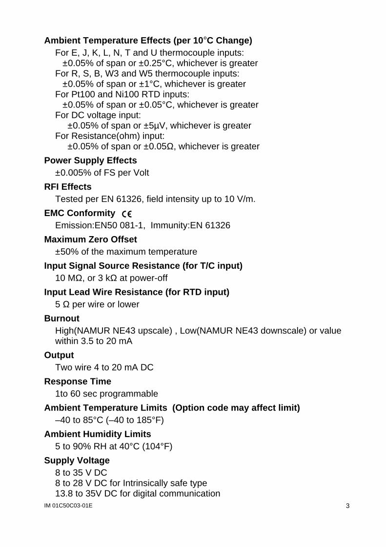
Ambient Temperature Effects (per 10°C Change)For E, J, K, L, N, T and U thermocouple inputs:
±0.05% of span or ±0.25°C, whichever is greaterFor R, S, B, W3 and W5 thermocouple inputs:
±0.05% of span or ±1°C, whichever is greaterFor Pt100 and Ni100 RTD inputs:
±0.05% of span or ±0.05°C, whichever is greaterFor DC voltage input:
±0.05% of span or ±5µV, whichever is greaterFor Resistance(ohm) input:
±0.05% of span or ±0.05Ω, whichever is greater
Power Supply Effects±0.005% of FS per Volt
RFI EffectsTested per EN 61326, field intensity up to 10 V/m.
EMC Conformity Emission:EN50 081-1, Immunity:EN 61326
Maximum Zero Offset±50% of the maximum temperature
Input Signal Source Resistance (for T/C input)10 MΩ, or 3 kΩ at power-off
Input Lead Wire Resistance (for RTD input)5 Ω per wire or lower
BurnoutHigh(NAMUR NE43 upscale) , Low(NAMUR NE43 downscale) or valuewithin 3.5 to 20 mA
OutputTwo wire 4 to 20 mA DC
Response Time1to 60 sec programmable
Ambient Temperature Limits (Option code may affect limit)–40 to 85°C (–40 to 185°F)
Ambient Humidity Limits5 to 90% RH at 40°C (104°F)
Supply Voltage8 to 35 V DC8 to 28 V DC for Intrinsically safe type13.8 to 35V DC for digital communication
IM 01C50C03-01E4
Load ResistanceLimitation: 0 to (E–8)/0.0236 [Ω], where E is power supply voltage.
IsolationInput/output isolated to 1500 V AC.
MountingDIN form B head mounting
TerminalsM3 screws
Weight50g(0.11 lb)
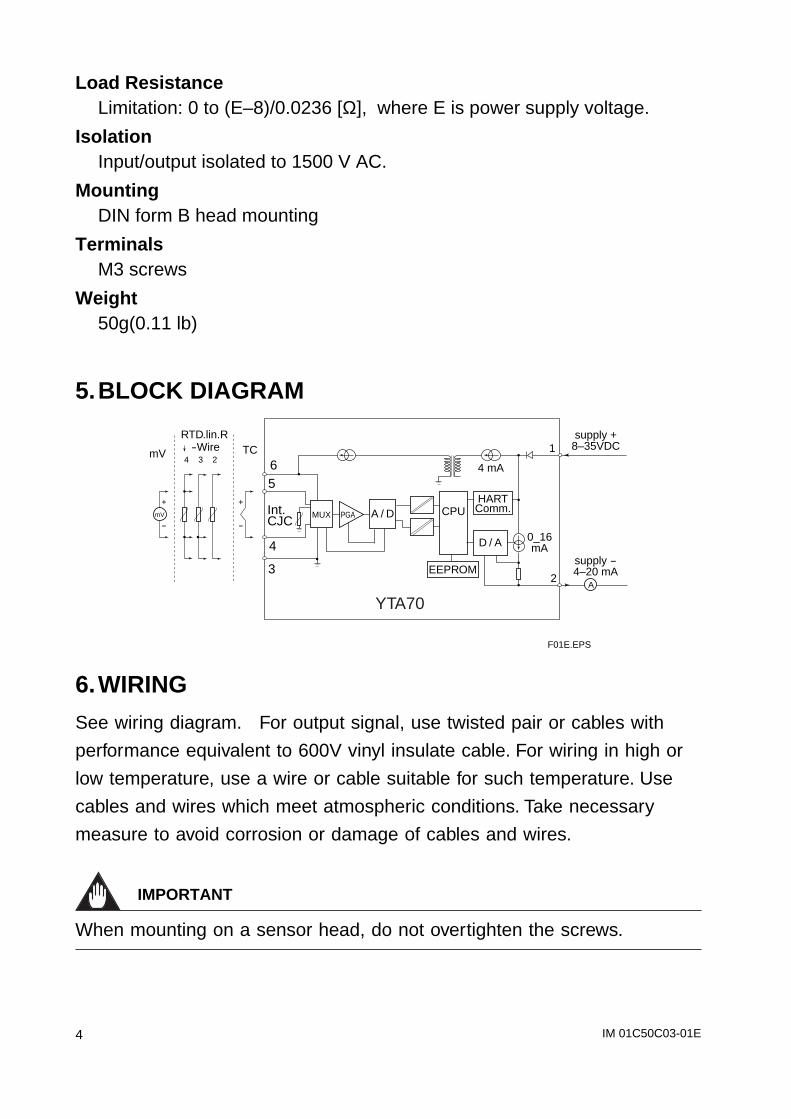
5.BLOCK DIAGRAM
mV
mV TC
MUX
4 mA
supply +8–35VDC
supply -4–20 mA
HARTComm.CPU
EEPROM
A / D
D / A
PGAInt.CJC
RTD.lin.R-Wire
+
-
+
-
4 3 2 6
2
1
5
4
3
0_16mA
F01E.EPS
A
YTA70
6.WIRING
See wiring diagram. For output signal, use twisted pair or cables with
performance equivalent to 600V vinyl insulate cable. For wiring in high or
low temperature, use a wire or cable suitable for such temperature. Use
cables and wires which meet atmospheric conditions. Take necessary
measure to avoid corrosion or damage of cables and wires.
IMPORTANT
When mounting on a sensor head, do not overtighten the screws.
IM 01C50C03-01E 5
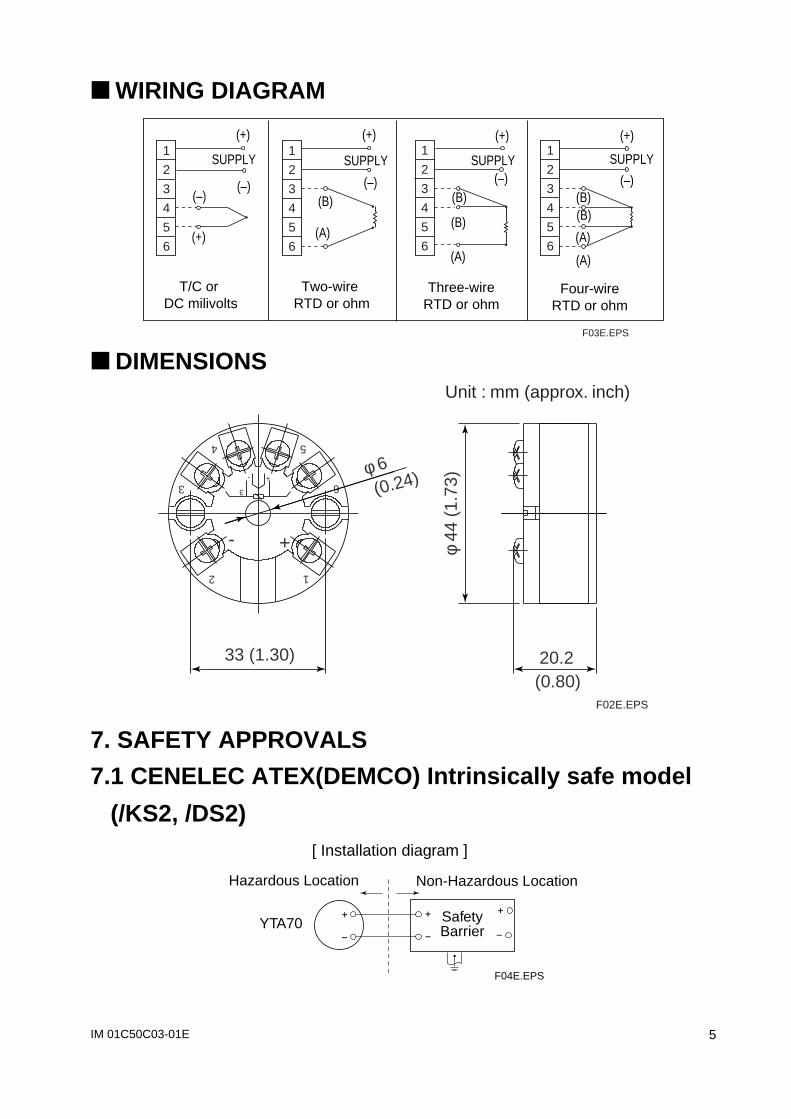
WIRING DIAGRAM
T/C or DC milivolts
Two-wire RTD or ohm
Three-wireRTD or ohm
Four-wireRTD or ohm
1
2
3
4
5
6
(–)
(+)
(B)(B)
1
2
3
4
5
6
(B)
(B)
1
2
3
4
5
6
(B)
(A)
SUPPLY1
2
3
4
5
6(A)
(A)
(A)
(–)
(+)
SUPPLY
(–)
(+)
SUPPLY(–)
(+)
SUPPLY
(–)
(+)
F03E.EPS
DIMENSIONS
6
54
3
2 1
3
- +
- +
(0.80)
(0.24)
20.233 (1.30)
φ 44
(1.
73)φ 6
Unit : mm (approx. inch)
F02E.EPS
7. SAFETY APPROVALS
7.1 CENELEC ATEX(DEMCO) Intrinsically safe model
(/KS2, /DS2)
Non-Hazardous LocationHazardous Location
YTA70 SafetyBarrier
F04E.EPS
[ Installation diagram ]
IM 01C50C03-01E6
Intrinsically safety rating(maximum value)Output/Power supply :Ui=28V, Ii=120mA, Pi=0.84W, Ci<1nF, Li<10µHSensor :Uo=28V, Io=93mA, Co<0.12µF, Lo<2 mH
Applicable in Zone0, 1, or 2
Maximum Ambient TemperatureFor T1-T4: 85°C, For T5/T6: 60°C
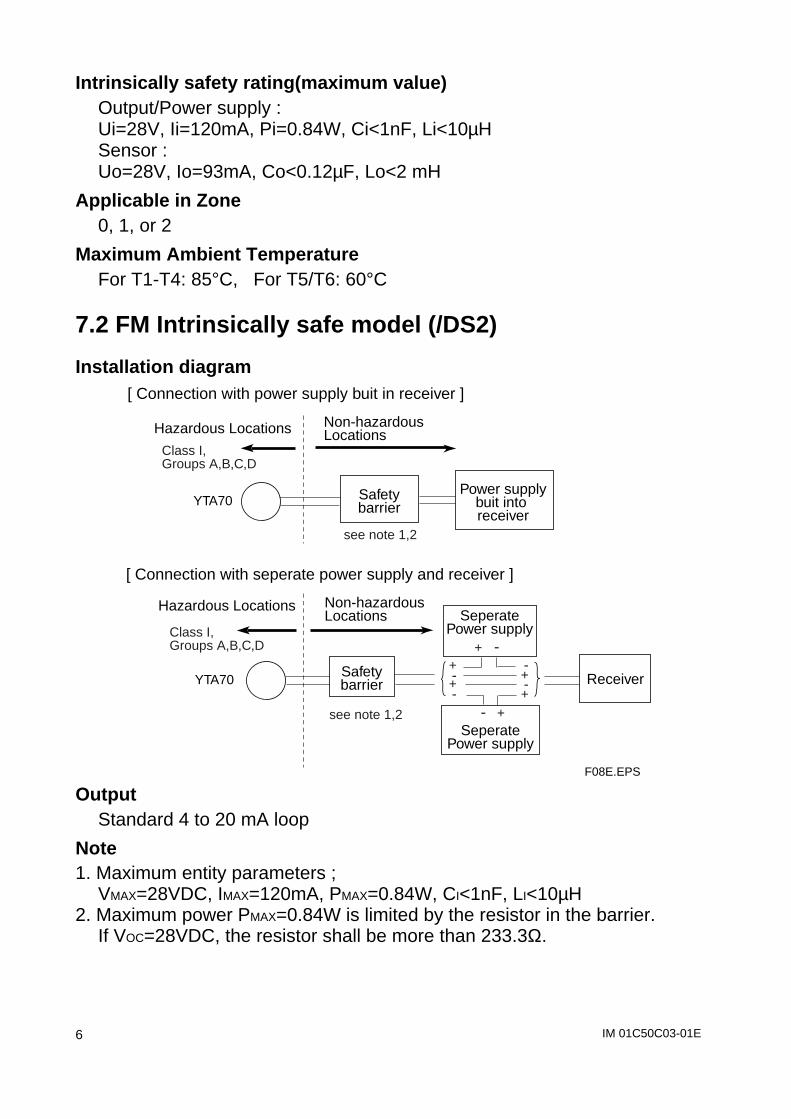
7.2 FM Intrinsically safe model (/DS2)
Installation diagram
see note 1,2
see note 1,2
Non-hazardous Locations
Hazardous Locations
YTA70Safetybarrier
Class I, Groups A,B,C,D
Power supplybuit into receiver
SeperatePower supply
+ -
SeperatePower supply
- +
Receiver
Non-hazardous LocationsHazardous Locations
YTA70 Safetybarrier
F08E.EPS
[ Connection with power supply buit in receiver ]
[ Connection with seperate power supply and receiver ]
Class I, Groups A,B,C,D
+-+-
-+-+
OutputStandard 4 to 20 mA loop
Note1. Maximum entity parameters ;
VMAX=28VDC, IMAX=120mA, PMAX=0.84W, CI<1nF, LI<10µH2. Maximum power PMAX=0.84W is limited by the resistor in the barrier.
If VOC=28VDC, the resistor shall be more than 233.3Ω.
IM 01C50C03-01E 7
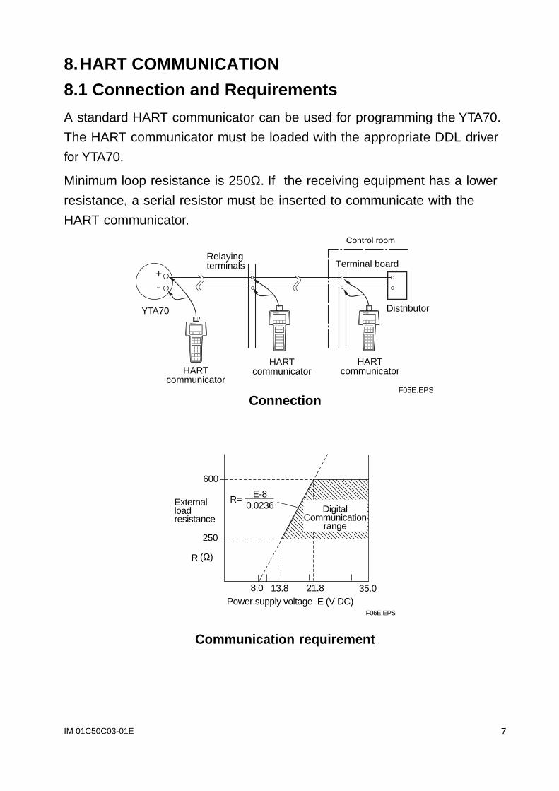
8.HART COMMUNICATION
8.1 Connection and Requirements
A standard HART communicator can be used for programming the YTA70.
The HART communicator must be loaded with the appropriate DDL driver
for YTA70.
Minimum loop resistance is 250Ω. If the receiving equipment has a lower
resistance, a serial resistor must be inserted to communicate with the
HART communicator.
HARTcommunicator
HARTcommunicator
HARTcommunicator
YTA70 Distributor
Control room
Terminal boardRelayingterminals
F05E.EPS
+-
Connection
(Ω)
Power supply voltage E (V DC)
600
250
R
8.0 13.8 21.8
Externalloadresistance
E-8 0.0236R=
DigitalCommunication
range
F06E.EPS
35.0
Communication requirement
IM 01C50C03-01E8
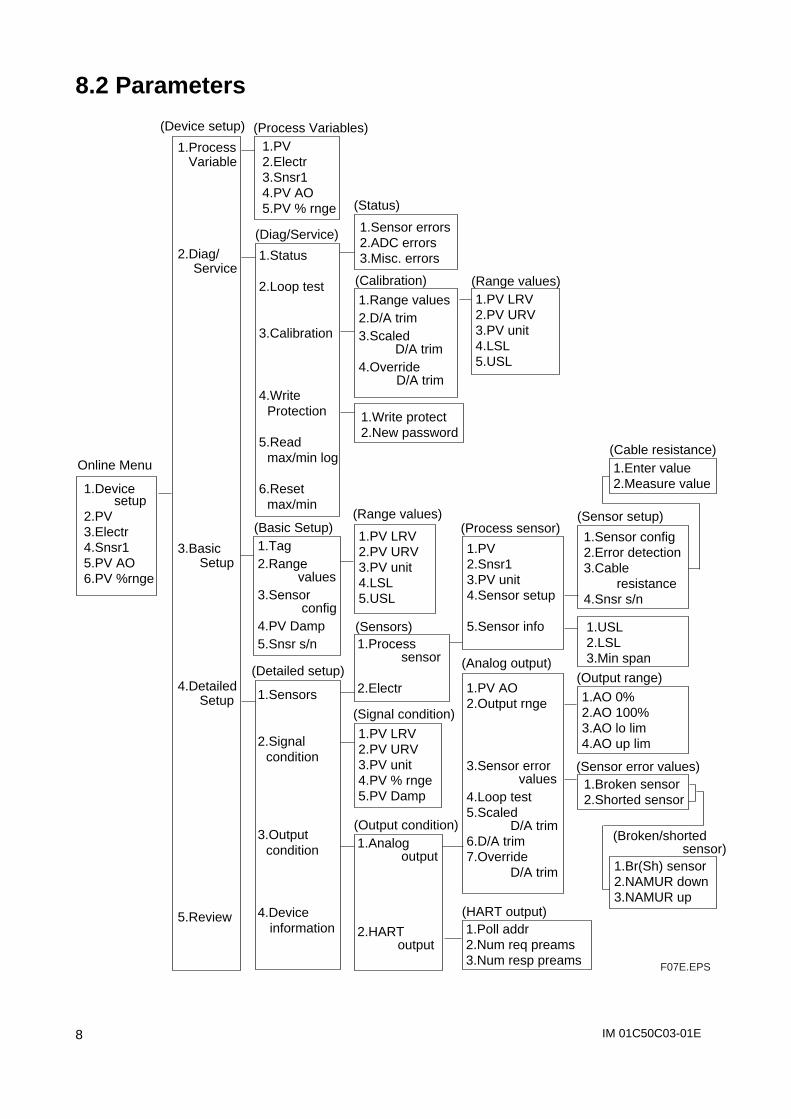
8.2 Parameters
1.Device setup
2.PV 3.Electr4.Snsr15.PV AO6.PV %rnge
1.Process Variable
2.Diag/ Service
3.Basic Setup
4.Detailed Setup
5.Review
1.PV2.Electr3.Snsr14.PV AO5.PV % rnge
1.PV LRV2.PV URV3.PV unit4.LSL5.USL
1.PV2.Snsr13.PV unit4.Sensor setup
5.Sensor info
1.PV AO2.Output rnge
3.Sensor error values
4.Loop test5.Scaled D/A trim6.D/A trim7.Override D/A trim
1.Poll addr2.Num req preams3.Num resp preams
1.Process sensor
2.Electr
1.Sensor config2.Error detection3.Cable resistance4.Snsr s/n
1.Broken sensor2.Shorted sensor
1.Sensor errors2.ADC errors3.Misc. errors
1.Range values2.D/A trim3.Scaled D/A trim4.Override
D/A trim
1.Write protect2.New password
1.Analog output
2.HART output
1.Status
2.Loop test
3.Calibration
4.Write Protection
5.Read max/min log
6.Reset max/min
Online Menu
(Device setup) (Process Variables)
(Diag/Service)
1.Tag2.Range values3.Sensor config4.PV Damp5.Snsr s/n
(Basic Setup)
1.Sensors
2.Signal condition
3.Output condition
4.Device information
(Detailed setup)
(Status)
(Calibration) (Range values)
1.PV LRV2.PV URV3.PV unit4.LSL5.USL
(Range values)
(Sensors)
1.PV LRV2.PV URV3.PV unit4.PV % rnge5.PV Damp
(Signal condition)
(Process sensor)
(Output condition)
(HART output)
(Analog output)
1.USL2.LSL3.Min span
1.AO 0%2.AO 100%3.AO lo lim4.AO up lim
(Output range)
(Sensor error values)
(Sensor setup)
1.Enter value2.Measure value
(Cable resistance)
1.Br(Sh) sensor2.NAMUR down3.NAMUR up
(Broken/shorted sensor)
F07E.EPS
IM 01C50C03-01E 9
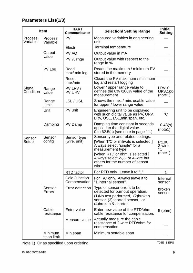
Parameters List(1/3)
Item Selection/ Setting Range Initial Setting
HARTCommunicator
Measured variables in engineering unit.Terminal temperature
Output value in mA
Output value with respect to the range in %
Reads the maximum / minimum PV stored in the memory
Clears the PV maximum / minimum log and restart loggingLower / upper range value to defines the 0% /100% value of the measurementShows the max. / min. usable value for upper / lower range value
Engineering unit to be displayed with such digital value as PV, URV, LRV, USL, LSL,min.span, etc.
Damping time constant in seconds applied to the digital value. 0 to 62.5(s) [see note in page 11.]Sensor type and related settings.[When T/C or milivots is selected ] Always select "single" for a measurement type. [When RTD or ohm is selected ] Always select 2-,3- or 4-wire but others for the number of sensor wires.
For RTD only. Leave it to "1".
For T/C only. Always leave it to "1.internal sensor".Type of sensor errors to be detected for burnout operation.(1)No test performed, (2)broken sensor, (3)shorted sensor, or (4)broken & shorted
Enter new value of the RTD/ohm cable resistance for compensation. Actually measure the cable resistance of 2-wire RTD/ohm for compensation.
Minimum settable span
PV
Electr
PV AO
PV % rnge
Read max/ min log
Reset max/min
PV LRV / PV URV
LSL / USL
PV unit
PV Damp
Sensor type (wire, unit)
RTD factorCold Junction Compensation
Error detection
Enter value
Measure value
Min.span
Process Variable
Signal Condition
Sensor Setup
ProcessVariable
Output value
PV Log
Range value
Range LimitUnit
Damping
Sensor config
Sensor Errors
Cable resistance
Minimum span limit
T03E_1.EPS
—
——
—
—
—
LRV: 0URV:100(note1)
—
°C
0.43(s)(note1)
Pt1003-wire°C(note1)
1
Internal sensor
broken sensor
5 (ohm)
—
—
Note 1) Or as specified upon ordering.
IM 01C50C03-01E10
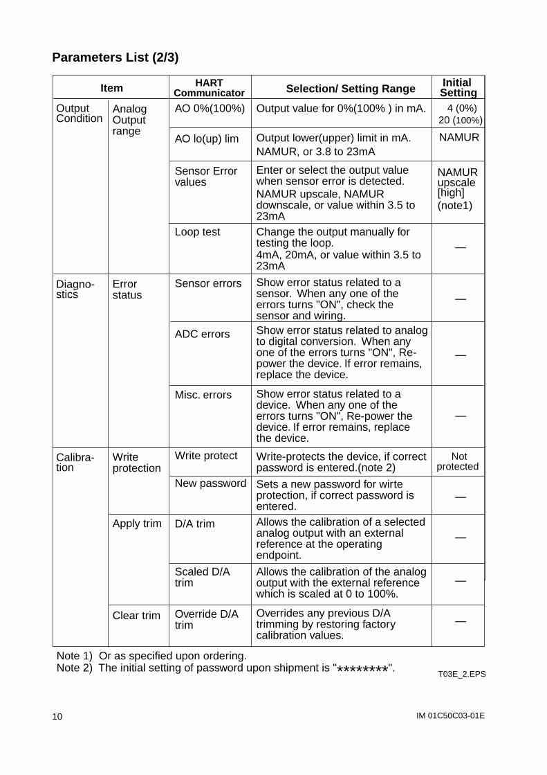
Parameters List (2/3)
Item Selection/ Setting Range Initial Setting
HARTCommunicator
Output value for 0%(100% ) in mA.
Output lower(upper) limit in mA.NAMUR, or 3.8 to 23mA
Enter or select the output value when sensor error is detected.NAMUR upscale, NAMUR downscale, or value within 3.5 to 23mAChange the output manually for testing the loop.4mA, 20mA, or value within 3.5 to 23mA
Show error status related to a sensor. When any one of the errors turns "ON", check the sensor and wiring.Show error status related to analog to digital conversion. When any one of the errors turns "ON", Re-power the device. If error remains, replace the device.
Show error status related to a device. When any one of the errors turns "ON", Re-power the device. If error remains, replace the device.
Write-protects the device, if correct password is entered.(note 2)
Sets a new password for wirte protection, if correct password is entered.Allows the calibration of a selected analog output with an external reference at the operating endpoint.
Allows the calibration of the analog output with the external reference which is scaled at 0 to 100%.
Overrides any previous D/A trimming by restoring factory calibration values.
AO 0%(100%)
AO lo(up) lim
Sensor Error values
Loop test
Sensor errors
ADC errors
Misc. errors
Write protect
New password
D/A trim
Scaled D/A trim
Override D/A trim
Output Condition
Diagno-stics
Calibra-tion
Analog Output range
Error status
Write protection
Apply trim
Clear trim
T03E_2.EPS
4 (0%)20 (100%)
NAMUR
NAMURupscale [high](note1)
—
—
—
—
Not protected
—
—
—
—
Note 1) Or as specified upon ordering.Note 2) The initial setting of password upon shipment is "********".
IM 01C50C03-01E 11
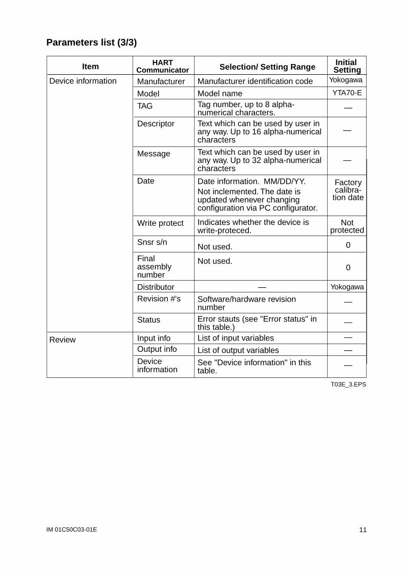
Parameters list (3/3)
Item Selection/ Setting Range Initial Setting
HARTCommunicator
Manufacturer identification code
Model nameTag number, up to 8 alpha-numerical characters.Text which can be used by user in any way. Up to 16 alpha-numerical characters
Text which can be used by user in any way. Up to 32 alpha-numerical characters
Date information. MM/DD/YY.Not inclemented. The date is updated whenever changing configuration via PC configurator.
Indicates whether the device is write-proteced.
Not used.
Not used.
—
Software/hardware revision numberError stauts (see "Error status" in this table.) List of input variables
List of output variables
See "Device information" in this table.
Manufacturer
Model
TAG
Descriptor
Message
Date
Write protect
Snsr s/n
Final assembly number
DistributorRevision #'s
Status
Input infoOutput info
Device information
Device information
Review
T03E_3.EPS
Yokogawa
YTA70-E
—
—
—
Factorycalibra-
tion date
Not protected
0
0
Yokogawa
—
—
—
—
—

IM 01C50C03-01E12
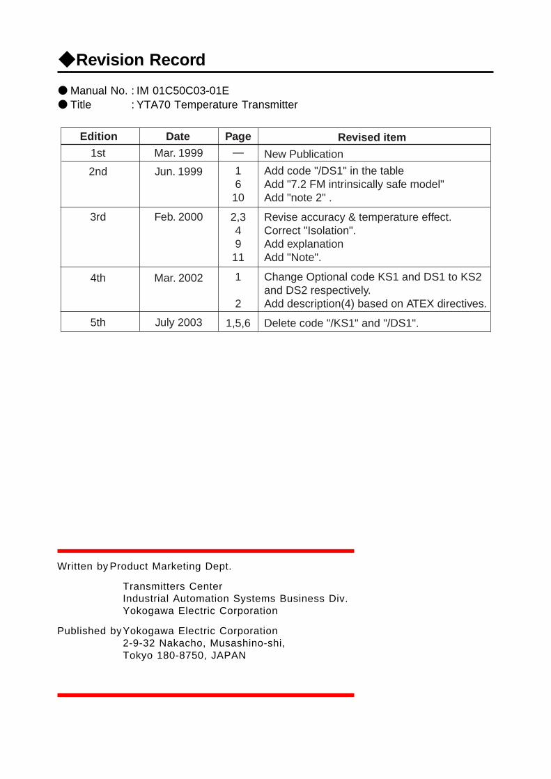
Revision Record
Manual No. : IM 01C50C03-01E Title : YTA70 Temperature Transmitter
Edition Date Page Revised item1st
2nd
3rd
4th
5th
Mar. 1999
Jun. 1999
Feb. 2000
Mar. 2002
July 2003
—
1 610
2,34911
1
2
1,5,6
New Publication
Add code "/DS1" in the tableAdd "7.2 FM intrinsically safe model"Add "note 2" .
Revise accuracy & temperature effect.Correct "Isolation".Add explanationAdd "Note".
Change Optional code KS1 and DS1 to KS2and DS2 respectively.Add description(4) based on ATEX directives.
Delete code "/KS1" and "/DS1".
Written by Product Marketing Dept.
Transmitters CenterIndustrial Automation Systems Business Div.Yokogawa Electric Corporation
Published byYokogawa Electric Corporation2-9-32 Nakacho, Musashino-shi,Tokyo 180-8750, JAPAN
YOKOGAWA ELECTRIC CORPORATIONHeadquarters2-9-32, Nakacho, Musashino-shi, Tokyo, 180-8750 JAPANFax: 81-422-55-0461
YOKOGAWA CORPORATION OF AMERICA, INC.Headquarters2 Dart Road, Newman, Ga. 30265-1040, U.S.A.Phone: 1-770-254-0400 Fax: 1-770-254-0928
YOKOGAWA EUROPE B.V.HeadquartersVanadiumweg 11, 3812 PX, Amersfoort, THE NETHERLANDSPhone: 31-334-64-1611 Fax:31-334-64-1610
YOKOGAWA AMERICA DO SUL S.A.Ameria Juruá, 149-Alphaville, Barueri, Sao Paulo, SP, BRAZILPhone: 55-11-7295-1433 Fax: 55-11-7295-1329
YOKOGAWA ENGINEERING ASIA PTE. LTD.5 Bedok South Rd., Singapore 469270, SINGAPOREPhone: 65-241-9933 Fax: 65-241-2606
HANKUK YOKOGAWA ELECTRIC CO., LTD.K.P.O.Box: 1481, Korean Reinsurance Bldg. 2F, 80 Susong-Dong,Chongro-ku, Seoul, KOREAPhone: 82-2-3701-0630/0650 Fax: 82-2-739-3987
YOKOGAWA AUSTRALIA PTY. LTD.Private mail bag 24, Centre Cpirt D3, 25-27 Paul Street North, North Ryde,N.S.W.2113, AUSTRALIAPhone: 61-2-9805-0699 Fax: 61-2-9888-1844
YOKOGAWA BLUE STAR LTD.40/4 Lavelle Road, Bangalore 560 001, INDIAPhone: 91-80-2271513 Fax: 91-80-2274270 Telex: 81-8458702 YBCO IN
Printed in Japan, 208(YGA)