Embed Size (px)
Citation preview
by
ALTA Serial Modbus (RTU/ASCII) Gateway
For Version 3.3
User’s Guide
Table of Contents
I. ABOUT THE SERIAL MODBUS GATEWAY 1
ALTA SERIAL MODBUS GATEWAY FEATURES 1
EXAMPLE APPLICATIONS 1
DEVICE SPECIFICATIONS 2
EXAMPLE NETWORK INTEGRATION 4
II. HOW YOUR GATEWAY WORKS 5
III. GATEWAY SECURITY 6
DATA SECURITY ON THE GATEWAY 6
GATEWAY COMMUNICATION SECURITY 6
iMONNIT SECURITY 6
IV. CONNECTING THE SERIAL MODBUS GATEWAY HARDWARE 7
CONNECTING TO A USB PROGRAMMING DONGLE 8
SERIAL MODBUS GATEWAY INDICATOR LIGHTS 8
V. MODBUS PROTOCOL IMPLEMENTATION 9
REGISTER SIZE 9
MULTI-BYTE FORMATTING 9
COMMUNICATION DEFAULTS 9
COMMUNICATIONS SETTINGS RESET JUMPER 9
FACTORY RESET 10
VI. MODBUS PROTOCOL IMPLEMENTATION 11
GATEWAY COILS 11
VERIFYING THAT THE WIRELESS IS ACTIVE 11
RESETTING THE GATEWAY 11
RESETTING THE WIRELESS NETWORK 11
RESETTING TO DEFAULT COMMUNICATIONS SETTINGS 12
RESETTING THE GATEWAY TO FACTORY SETTINGS 12
VIEWING AND MODIFYING MODBUS COMMUNICATIONS 12
SETTING GATEWAY TIME 13
VIEWING REGISTERED WIRELESS DEVICES 13
ADDING A WIRELESS DEVICE TO THE GATEWAY 13PAGE II
VERIFYING WIRELESS DEVICE ACTIVITY 14
VIEWING WIRELESS DEVICE DATA (FAST READ METHOD) 14
VIEWING WIRELESS DEVICE DATA (ADVANCED METHOD) 14
CONFIGURING WIRELESS DEVICES 15
CONFIGURATION RULES TO ABIDE BY 15
WIRELESS DEVICE SYNC SETTING 15
VII. UPGRADING GATEWAY FIRMWARE 17
REFERENCE SECTION 18
GATEWAY COILS 18
WIRELESS DEVICE COILS 19
GATEWAY REGISTERS 21
WIRELESS DEVICE LIST REGISTERS 24
FAST READ REGISTERS 24
WIRELESS DEVICE REGISTERS 25
SUPPORT 30
WARRANTY INFORMATION 30
CERTIFICATIONS 32
PAGE III
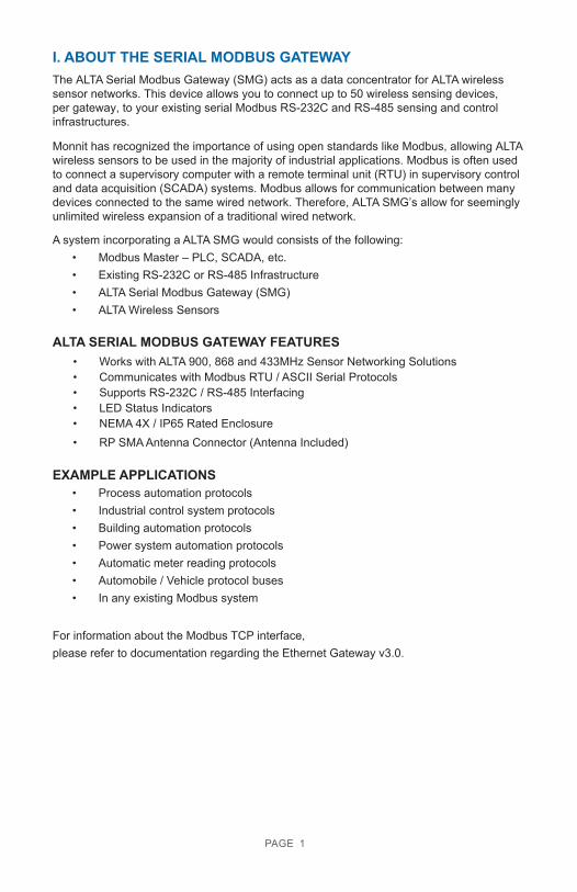
I. ABOUT THE SERIAL MODBUS GATEWAYThe ALTA Serial Modbus Gateway (SMG) acts as a data concentrator for ALTA wireless sensor networks. This device allows you to connect up to 50 wireless sensing devices, per gateway, to your existing serial Modbus RS-232C and RS-485 sensing and control infrastructures.
Monnit has recognized the importance of using open standards like Modbus, allowing ALTA wireless sensors to be used in the majority of industrial applications. Modbus is often used to connect a supervisory computer with a remote terminal unit (RTU) in supervisory control and data acquisition (SCADA) systems. Modbus allows for communication between many devices connected to the same wired network. Therefore, ALTA SMG’s allow for seemingly unlimited wireless expansion of a traditional wired network.
A system incorporating a ALTA SMG would consists of the following:• Modbus Master – PLC, SCADA, etc.• Existing RS-232C or RS-485 Infrastructure• ALTA Serial Modbus Gateway (SMG)• ALTA Wireless Sensors
ALTA SERIAL MODBUS GATEWAY FEATURES• Works with ALTA 900, 868 and 433MHz Sensor Networking Solutions• Communicates with Modbus RTU / ASCII Serial Protocols• Supports RS-232C / RS-485 Interfacing• LED Status Indicators• NEMA 4X / IP65 Rated Enclosure• RP SMA Antenna Connector (Antenna Included)
EXAMPLE APPLICATIONS• Process automation protocols• Industrial control system protocols• Building automation protocols• Power system automation protocols• Automatic meter reading protocols• Automobile / Vehicle protocol buses• In any existing Modbus system
For information about the Modbus TCP interface, please refer to documentation regarding the Ethernet Gateway v3.0.
PAGE 1
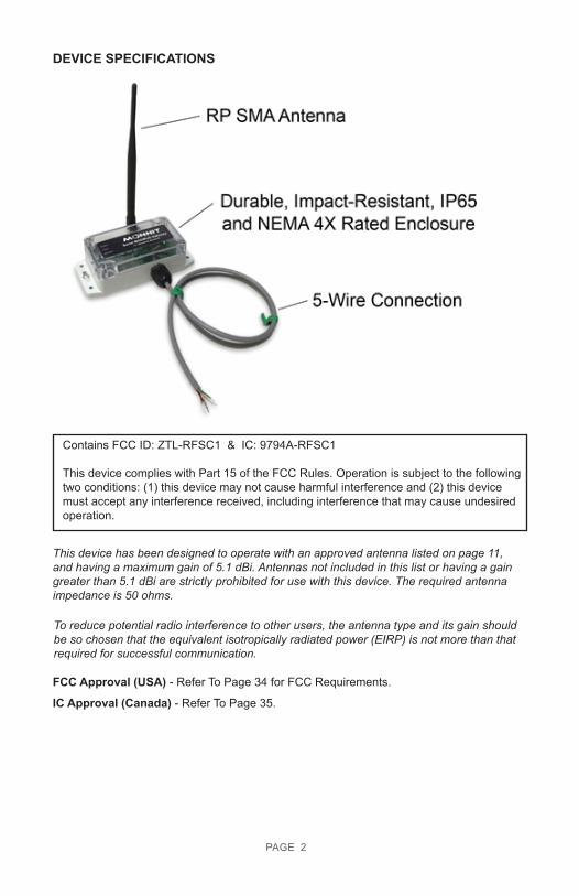
DEVICE SPECIFICATIONS
Contains FCC ID: ZTL-RFSC1 & IC: 9794A-RFSC1
This device complies with Part 15 of the FCC Rules. Operation is subject to the following two conditions: (1) this device may not cause harmful interference and (2) this device must accept any interference received, including interference that may cause undesired operation.
This device has been designed to operate with an approved antenna listed on page 11, and having a maximum gain of 5.1 dBi. Antennas not included in this list or having a gain greater than 5.1 dBi are strictly prohibited for use with this device. The required antenna impedance is 50 ohms.
To reduce potential radio interference to other users, the antenna type and its gain should be so chosen that the equivalent isotropically radiated power (EIRP) is not more than that required for successful communication.
FCC Approval (USA) - Refer To Page 34 for FCC Requirements.
IC Approval (Canada) - Refer To Page 35.
PAGE 2
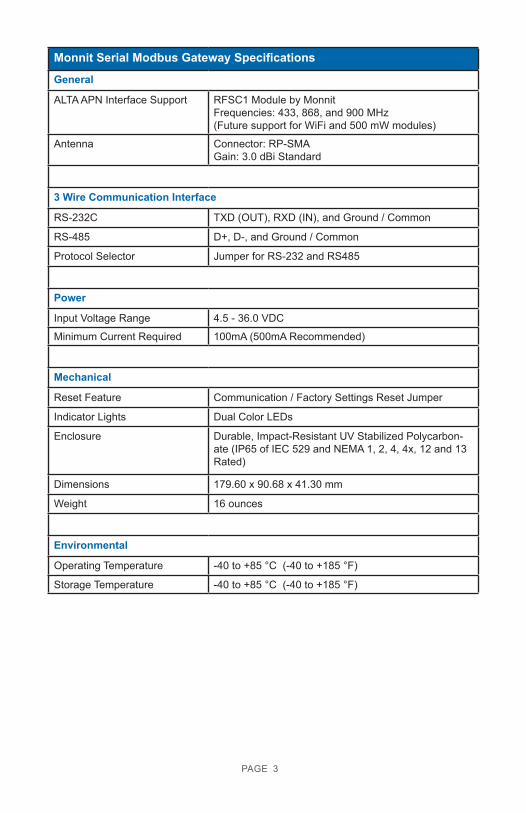
Monnit Serial Modbus Gateway Specifications
General
ALTA APN Interface Support RFSC1 Module by MonnitFrequencies: 433, 868, and 900 MHz(Future support for WiFi and 500 mW modules)
Antenna Connector: RP-SMAGain: 3.0 dBi Standard
3 Wire Communication Interface
RS-232C TXD (OUT), RXD (IN), and Ground / Common
RS-485 D+, D-, and Ground / Common
Protocol Selector Jumper for RS-232 and RS485
Power
Input Voltage Range 4.5 - 36.0 VDC
Minimum Current Required 100mA (500mA Recommended)
Mechanical
Reset Feature Communication / Factory Settings Reset Jumper
Indicator Lights Dual Color LEDs
Enclosure Durable, Impact-Resistant UV Stabilized Polycarbon-ate (IP65 of IEC 529 and NEMA 1, 2, 4, 4x, 12 and 13 Rated)
Dimensions 179.60 x 90.68 x 41.30 mm
Weight 16 ounces
Environmental
Operating Temperature -40 to +85 °C (-40 to +185 °F)
Storage Temperature -40 to +85 °C (-40 to +185 °F)
PAGE 3
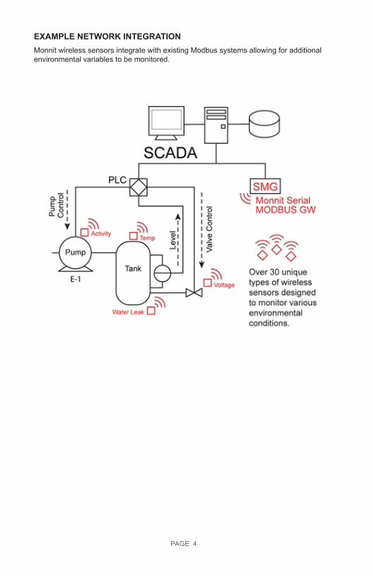
EXAMPLE NETWORK INTEGRATIONMonnit wireless sensors integrate with existing Modbus systems allowing for additional environmental variables to be monitored.
PAGE 4
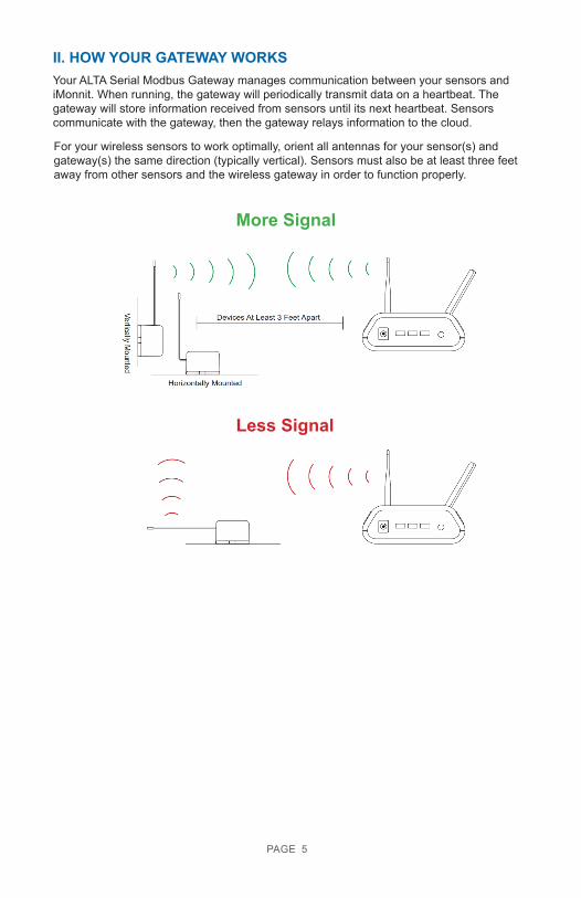
II. HOW YOUR GATEWAY WORKSYour ALTA Serial Modbus Gateway manages communication between your sensors and iMonnit. When running, the gateway will periodically transmit data on a heartbeat. The gateway will store information received from sensors until its next heartbeat. Sensors communicate with the gateway, then the gateway relays information to the cloud.
For your wireless sensors to work optimally, orient all antennas for your sensor(s) and gateway(s) the same direction (typically vertical). Sensors must also be at least three feet away from other sensors and the wireless gateway in order to function properly.
More Signal
Less Signal
PAGE 5
III. GATEWAY SECURITYThe ALTA Serial Modbus Gateway has been designed and built to securely manage data from sensors monitoring your environment and equipment. Hacking from botnets are in the headlines, Monnit Corporation has taken extreme measures to ensure your data security is handled with the utmost care and attention to detail. The same methods utilized by financial institutions to transmit data are also used in Monnit security infrastructure. Security features of the gateway include tamper proof network interfaces, data encryption, and bank-grade security.
Monnit’s proprietary sensor protocol uses low transmit power and specialized radio equipment to transmit application data. Wireless devices listening on open communication protocols cannot eavesdrop on sensors. Packet level encryption and verification is key to ensuring traffic isn’t altered between sensors and gateways. Paired with best-in-class range and power consumption protocol, all data is transmitted securely from your devices. Thereby ensuring a smooth, worry-free, experience.
SENSOR COMMUNICATION SECURITYMonnit sensor to gateway secure wireless tunnel is generated using ECDH-256 (Elliptic Curve Diffie-Hellman) public key exchange to generate a unique symmetric key between each pair of devices. Sensors and gateways use this link specific key to process packet level data with hardware accelerated 128-bit AES encryption which minimizes power consumption to provide industry best battery life. Thanks to this combination, Monnit proudly offers robust bank-grade security at every level.
DATA SECURITY ON THE GATEWAY
The ALTA Serial Modbus Gateway is designed to prevent prying eyes from accessing the data that is stored on the sensors. The ALTA Serial Modbus Gateway does not run on an off the shelf multi-function OS (operating system). Instead it runs a purpose specific real-time embedded state machine that cannot be hacked to run malicious processes. There are also no active interface listeners that can be used to gain access to the device over the network. The fortified gateway secures your data from attackers and secures the gateway from becoming a relay for malicious programs.
iMONNIT SECURITY
iMonnit is the online software and central hub for configuring your device settings. All data is secured on dedicated servers operating Microsoft SQL Server. Access is granted through the iMonnit user interface, or an Application Programming Interface (API) safeguarded by 256-bit Transport Layer Security (TLS 1.2) encryption. TLS is blanket of protection to encrypt all data exchanged between iMonnit and you. The same encryption is available to you whether you are a Basic user of Premiere user of iMonnit. You can rest assured that your data is safe with iMonnit.
PAGE 6
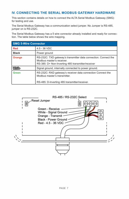
IV. CONNECTING THE SERIAL MODBUS GATEWAY HARDWAREThis section contains details on how to connect the ALTA Serial Modbus Gateway (SMG) for testing and use.
The Serial Modbus Gateway has a communication select jumper. No Jumper is RS-485, jumper on is RS-232C.
The Serial Modbus Gateway has a 5 wire connector already installed and ready for connec-tion. The table below shows the wire mapping.
SMG 5-Wire ConnectorRed 4.5 - 36 VDC
Black Power ground
Orange RS-232C: TXD gateway’s transmitter data connection. Connect the Modbus master’s receiver.RS-385: D+ Non-Inverting 485 transmitter/receiver
White Signal ground, internally connected to power ground.
Green RS-232C: RXD gateway’s receiver data connection Connect the Modbus master’s transmitter.
RS-485: D-Inverting 485 transmitter/receiver.
PAGE 7

CONNECTING TO A USB PROGRAMMING DONGLEMonnit provides Modbus configuration software that presents a GUI to the user and makes interfacing to the Modbus gateway easy. Monnit also provides a USB to RS485 dongle to connect the hardware to a PC. To use the USB to RS485 dongle, connect the wires from the Modbus gateway as shown in the illustration below.
White - Signal Ground (Not Connected)Red - 4.5 – 36 VDCGreen - ReceiveOrange - TransmitBlack - 4.5 – 36 VDC
Note: The white wire is not used with the USB programming dongle. The white should be left unconnected but protected to prevent accidental shorting.
* Any COM port in a computer may be used with the software.
The USB driver for this device can be downloaded at: ftdichip.com/Drivers/VCP.htm. Select the version that is compatible with your PC operating system.
SERIAL MODBUS GATEWAY INDICATOR LIGHTSSystem - Indicates gateway status. A green light indicates ready and working, a red light indicates there is a hardware problem.
Wired - Indicates connectivity with Modbus system. A green light indicates ready and working, a red light indicates there is a problem. A flashing green light indicates active communication.
Wireless - Indicates wireless sensor network activity. A green light indicates ready and working, a red light indicates that no network has been formed (no sensors are registered). A flashing green light indicates radio traffic from the sensors.
Indicator Light Sequences:
Startup - All indicators flash red and green for ~4 seconds. Internal Memory Failure - All indicators stay red after startup.COM Reset - “Wired” indicator will flash red (1x/sec).
Factory Reset - All indicators will flash red quickly (5x/sec).
PAGE 8
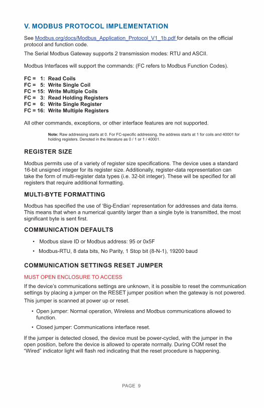
V. MODBUS PROTOCOL IMPLEMENTATIONSee Modbus.org/docs/Modbus_Application_Protocol_V1_1b.pdf for details on the official protocol and function code.The Serial Modbus Gateway supports 2 transmission modes: RTU and ASCII.
Modbus Interfaces will support the commands: (FC refers to Modbus Function Codes).
FC = 1: Read CoilsFC = 5: Write Single CoilFC = 15: Write Multiple CoilsFC = 3: Read Holding RegistersFC = 6: Write Single RegisterFC = 16: Write Multiple Registers
All other commands, exceptions, or other interface features are not supported.
Note: Raw addressing starts at 0. For FC-specific addressing, the address starts at 1 for coils and 40001 for holding registers. Denoted in the literature as 0 / 1 or 1 / 40001.
REGISTER SIZE
Modbus permits use of a variety of register size specifications. The device uses a standard 16-bit unsigned integer for its register size. Additionally, register-data representation can take the form of multi-register data types (i.e. 32-bit integer). These will be specified for all registers that require additional formatting.
MULTI-BYTE FORMATTING
Modbus has specified the use of ‘Big-Endian’ representation for addresses and data items. This means that when a numerical quantity larger than a single byte is transmitted, the most significant byte is sent first.
COMMUNICATION DEFAULTS
• Modbus slave ID or Modbus address: 95 or 0x5F
• Modbus-RTU, 8 data bits, No Parity, 1 Stop bit (8-N-1), 19200 baud
COMMUNICATION SETTINGS RESET JUMPER
MUST OPEN ENCLOSURE TO ACCESS If the device’s communications settings are unknown, it is possible to reset the communication settings by placing a jumper on the RESET jumper position when the gateway is not powered. This jumper is scanned at power up or reset.
• Open jumper: Normal operation, Wireless and Modbus communications allowed to function.
• Closed jumper: Communications interface reset.
If the jumper is detected closed, the device must be power-cycled, with the jumper in the open position, before the device is allowed to operate normally. During COM reset the “Wired” indicator light will flash red indicating that the reset procedure is happening.
PAGE 9

FACTORY RESET
MUST OPEN ENCLOSURE TO ACCESS.
While in communication reset state, if the device remains powered and the reset jumper is deliberately removed and replaced twice, a factory reset will occur on the device. All indicators will flash red quickly (5x/sec) indicating that the device has been successfully reset. Power-cycle the device with the jumper in the open position to allow normal operation.
NOTE: a factory reset will remove all known sensors and settings from the device.
PAGE 10
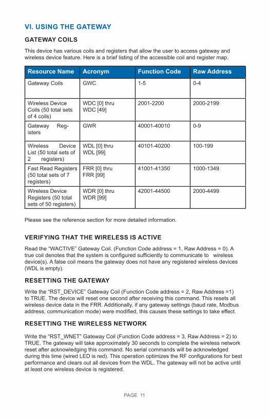
VI. USING THE GATEWAY
GATEWAY COILSThis device has various coils and registers that allow the user to access gateway and wireless device feature. Here is a brief listing of the accessible coil and register map.
Resource Name Acronym Function Code Raw Address
Gateway Coils GWC 1-5 0-4
Wireless Device Coils (50 total sets of 4 coils)
WDC [0] thruWDC [49]
2001-2200 2000-2199
Gateway Reg-isters
GWR 40001-40010 0-9
Wireless Device List (50 total sets of 2 registers)
WDL [0] thruWDL [99]
40101-40200 100-199
Fast Read Registers (50 total sets of 7 registers)
FRR [0] thruFRR [99]
41001-41350 1000-1349
Wireless Device Registers (50 total sets of 50 registers)
WDR [0] thruWDR [99]
42001-44500 2000-4499
Please see the reference section for more detailed information.
VERIFYING THAT THE WIRELESS IS ACTIVERead the “WACTIVE” Gateway Coil. (Function Code address = 1, Raw Address = 0). A true coil denotes that the system is configured sufficiently to communicate to wireless device(s). A false coil means the gateway does not have any registered wireless devices (WDL is empty).
RESETTING THE GATEWAYWrite the “RST_DEVICE” Gateway Coil (Function Code address = 2, Raw Address =1) to TRUE. The device will reset one second after receiving this command. This resets all wireless device data in the FRR. Additionally, if any gateway settings (baud rate, Modbus address, communication mode) were modified, this causes these settings to take effect.
RESETTING THE WIRELESS NETWORK
Write the “RST_WNET” Gateway Coil (Function Code address = 3, Raw Address = 2) to TRUE. The gateway will take approximately 30 seconds to complete the wireless network reset after acknowledging this command. No serial commands will be acknowledged during this time (wired LED is red). This operation optimizes the RF configurations for best performance and clears out all devices from the WDL. The gateway will not be active until at least one wireless device is registered.
PAGE 11
RESETTING TO DEFAULT COMMUNICATIONS SETTINGSWrite the “RST_COM” Gateway Coil (Function Code address = 4, Raw Address = 3) to TRUE. After setting this coil to true, a device reset command must be issued (or power cycling) before any of the new settings will take effect.
Resets the baud rate, mode, and device ID back to defaults, which are respectively: 19200, RTU: 8-N-1, 95.
RESETTING THE GATEWAY TO FACTORY SETTINGS
Write the “RST_FACTORY” Gateway Coil (Function Code address = 5, Raw Address = 4) to TRUE. After setting this coil to true, the device will reset automatically one second after the write coil command is acknowledged. No manual reset is required.
VIEWING AND MODIFYING MODBUS COMMUNICATION SETTINGS
The BAUDRATE Gateway Register (Function Code 40006, Raw Address 5) contains the baud rate setting. Encoded options are:
0 : 24001 : 48002 : 96003 : 192004 : 384005 : 57600
6 : 115200
Example: Writing a value of 2 to this register will effectively change the baud rate to 9600.
The COMMODE Gateway Register Function Code address = 40007, Raw Address =6)
contains the following encoded options:
0 : RTU : 8-N-21 : RTU : 8-N-12 : RTU : 8-E-13 : RTU : 8-O-14 : ASCII : 7-N-25 : ASCII : 7-E-16 : ASCII : 7-O-1
Example: Writing a value of 2 to this register will effectively change the communication mode to RTU: 8-E-1.
The ADDRESS Gateway Register (Function Code address = 40008, Raw Address =7) contains the address used by the Modbus interface. Values of 1-247 are permitted to be written.
Modifications to these registers are applied after a power-cycle or gateway reset sequence.
Please see Ref.4 for more information.
PAGE 12
SETTING GATEWAY TIMEGWTIME, consisting of GWTIME_H and GWTIME_L @ 40011-40012 or RAW 10-11, is a UInt32 value that by default represents the time in seconds from the point the gateway was powered on or reset. A user, which has access to some form of external time reference, can write to these registers to set time. It’s required that GWTIME_H is written before GWTIME_L is written. Once GWTIME_L is written the gateways time is officially updated with the contents of GWTIME_H/L. Reading these register will retrieve the gateway’s time in seconds.
The reference time used to set this time only needs to be meaningful to the application it is used in. Most applications do not require the Serial Modbus Gateway to reference any time. If an application uses wireless device synchronization settings, then the time must be set. For example, Current time is September 1st, 2016 at 17:05:15. If September 1st, 2016, 00:00:00 was referenced as the beginning time, then the GWTIME can be set to (17 * 3600) + (5 * 60) + 15 = 61515. If January 1st, 2016, 00:00:00 was referenced as the beginning time, then GWTIME can be set to (245 * 24 * 3600) + (17 * 3600) + (5 * 60) + 15 = 21229515. Both time references result in accurate synchronization of remote wireless devices.
VIEWING REGISTERED WIRELESS DEVICESThe WD_CNT Gateway Register (Function Code address = 40004, Raw Address =3) con-tains the number of registered devices in the Wireless Device List (WDL). A Value of 0 here denotes that no devices are registered and the wireless is disabled.
The WDL consists of 50 set of 2-paired registers that represents the Serial Identifier (SID) for the register device. These registers can be read to discover the location of a specific device in the list (SLOT).
Note: You need register at least one sensor to view / edit wireless device register data (WDR). Please see Ref.4 for more information.
ADDING A WIRELESS DEVICE TO THE GATEWAYEach Monnit device has a 32-bit serial identifier (SID). To add a wireless device, this SID is written to the intended SLOT (two registers at a time) in WDL registers.
Note: The two SLOT ID registers must be written to using FC = 16 (Write to Multiple Regis-ters) otherwise an error will be generated. See section 3.0 for more details.
SLOT IDs can only be added one at a time.
For example: If you have sensor 43527 in hand and you wanted to add this to SLOT 0, you would write the following.
40101 / 100 0
40102 / 101 43527
To move a wireless device from one slot to another, the SID of the wireless device only needs to be written to the new SLOT. The old SLOT will be erased and prepared for future use.
To delete a wireless device from the list, write a 0,0 into the SLOT and the device will be erased and the SLOT is prepared for future use.
PAGE 13
When registering the first wireless device, the second LED will shift to red signifying there is no wired communication available, then the third LED will start flashing while the wireless network resets. It is recommended that you wait approximately 30 seconds (until all LEDs turn green, signifying a successful network reset) after registering the first device, before attempting any other tasks.
If the WDL SLOT is written to incorrectly, a “Modbus IO error message” is returned.
Please see Ref.3 for more information.
VERIFYING WIRELESS DEVICE ACTIVITYAfter a device is registered, the SLOT it was registered at can be verified by reading the WDL. Once the slot is known, a user can read the WDC [SLOT], WDR [SLOT], and FRR [SLOT] associated with the wireless device.
If a wireless device is registered, but is not actively communicating, the ACTIVE coil @ WDC[SLOT] offset 0 will be false.
When a wireless device is actively communicating, the ACTIVE coil @ WDC[SLOT] offset 0
will be true.
VIEWING WIRELESS DEVICE DATA (FAST READ METHOD)All Monnit Wireless Devices have two pieces of commonly useful data:
1. If a threshold is breached or if the device is in an exception state.2. The acquired data measurement.
Using the FRR, a user can quickly collect new data generated by multiple devices registered on the gateway. The purpose of these registers is to allow for efficient access to the remote wireless device’s most current data.
When new data is available from any Wireless device the FRR is updated with the newly reported values. The FRR will zero itself out if no new data is received within a defined period. The defined period is specified in the Wireless Device Registers offset 18.
Any write to the first address in the FRR will zero out the latest measurement and age. These records consist of seven (7) registers per wireless device. The format of these records are: AGE, DATA_0, DATA_1, DATA_2, DATA_3, BATTERY, RSSI.
Fnct. Code ADDRESS = 41001+ (7 * SLOT)Raw ADDRESS FORMULA = 1000+(7 * SLOT)
Please see Ref.5 for more information on these registers.
VIEWING WIRELESS DEVICE DATA (ADVANCED METHOD)For a user to see more data about a devices exception and activity status, the ACTIVE coil @ WDC[SLOT] offset 0 and EXCEPTION coil @ WDC[SLOT] offset 1 can be queried.
WDC F.C. FORMULA=2001+(4*SLOT)+OFFSETWDC RAW ADDR FORMULA=2000+(4*SLOT)+OFFSET
Please see Ref.2 for more information on these coils.
PAGE 14
For a user to see the detailed data from a device, read register WDR [SLOT] offset 5 - 15. This will return device battery voltage, signal strength, and specific status and data from the device.
WDRF.C.FORMULA=42001+(50* SLOT) + OFFSETWDR RAW ADDR FORMULA=2000+(50 * SLOT) + OFFSET
Please see Ref.6 for more details on these registers.
CONFIGURING WIRELESS DEVICES (STANDARD REQUESTS)
For a user to view and modify wireless device settings, read/write to register WDR[SLOT] offset 19-23. These registers contain information and settings relating to communication intervals, retry, and failure recovery behaviors. Please see Ref.6 for more details on these registers.
After changes are made to these registers, the user can use the PENDING_CFG coil @ WDC[SLOT] offset 2 to check the status of these changes. When this coil is true, the pending changes have not been communicated with the wireless device. When this coil is reset to false, the wireless device has been updated with the change. We recommend one update at a time.
CONFIGURATION RULES TO ABIDE BYThere are two important rules to obey when setting Wireless Devices, to ensure optimum stability.
CFG_INTERVAL_EXCEPTION ≤ CFG_INTERVAL_STANDARD
CFG_INTERVAL_STANDARD÷CFG_INT_TYPE_MEAS_PER_RPT≥ 1And
CFG_INTERVAL_EXCEPTION÷CFG_INT_TYPE_MEAS_PER_RPT≥1
WIRELESS DEVICE SYNC SETTING
All “Interval Type” wireless devices contain configuration CFG_INT_TYPE_SYNC @ offset 45 which enables them to synchronize data reporting to an external clock. Value can range from 0 – 5. If the value is 0 [default], the wireless devices do not synchronize report interval and will report data in respect to its startup time. If the value is 1 – 5, the wireless device attempts to track its report time based on the Serial Modus Gateway’s time. It is important that GWTIME in the Gateway Registers is set with an appropriate time reference. For instance, GWTIME could be set to the number of seconds from January 1st, 2010, 00:00:00. Now when the Sync setting is not set to 0, the wireless device will constantly adjust its reporting interval to closely track a modulus of the gateway’s time. As an example, if a wireless temperature sensor has a report interval of 30 minutes and this sync setting is enabled, this sensor will report its data near to 00:00, 00:30, 1:00, 1:30, …, etc.
The difference in the enabled values of 1 – 5 correlate to the number of “random seconds” that is included in the calculation of next report interval. Theses setting are useful in managing networks of different sizes. If 20 sensors were all configured to synchronize and deliver data at the exact same time, the RF collisions would cripple the sensor network. Please see table below for recommend settings to be used with specific network sizes.
PAGE 15
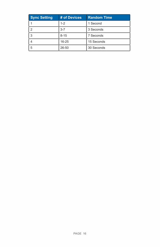
Sync Setting # of Devices Random Time1 1-2 1 Second
2 3-7 3 Seconds
3 8-15 7 Seconds
4 16-25 15 Seconds
5 26-50 30 Seconds
PAGE 16

VII. UPGRADING GATEWAY FIRMWAREGateway Versions 3.0.0.0 and above are remotely upgradeable. To upgrade the SMG, you will need to already have or download the Monnit Modbus Sensor Gateway software executable and possess a Monnit Serial Modbus Gateway to USB Programming dongle. Once these are in place, obtain and the latest file upgrade from Monnit Support and save the file locally on your PC.
Put the SMG in boot loader mode by opening the enclosure and accessing the RESET Jumper. Place the jumper over the pins and remove and replace at least 5 times.
When the jumper is placed on the RESET terminals for the first time, the middle light will flash red while the other lights are off. Removing and replacing the jumper twice will then cause the all three lights to flash on and off quickly in red. Removing and replacing the jumper four more times will cause the top Gateway light to go solid red, while the other lights are off. Removing the jumper for the final time will cause all three lights to illuminate solid red. Your SMG is now in boot loader mode.
Use the Monnit Modbus Sensor Gateway software and find the menu “Gateway Commands”. At the bottom, select the option “Upgrade Gateway Firmware”. Select the upgrade file and click on “Open”.
While the code loads, the status is displayed in the bottom left of the Monnit Modbus Sensor Gateway Software. The lights on the SMG will flash red and off during the process. Upon successful upgrade, the SMG will then reboot. Note that all registered sensors will be eliminated and the new firmware will be in a fresh from factory state.
If an error occurs during the process, factory reset the gateway using the jumper and try again.
PAGE 17
REFERENCE SECTIONComplete Gateway Features and Resource Mapping Reference
Through the Modbus interface, the following features are available for access by a Modbus master. All coils and registers are available for read or write access through the Modbus address mapping presented here.
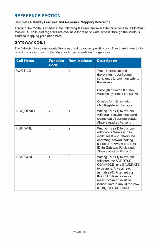
GATEWAY COILSThe following table represents the supported gateway specific coils. These are intended to report the status, control the state, or trigger events on the gateway.
Coil Name Function Code
Raw Address Description
WACTIVE 1 0 True (1) denotes that the system is configured sufficiently to communicate to the sensor.
False (0) denotes that the wireless system is not active
Causes for this include:- No Registered Sensors.
RST_DEVICE 2 1 Writing True (1) to this coil will force a device reset and cleans out all current status. Always read as False (0).
RST_WNET 3 2 Writing True (1) to this coil will force a Wireless Net-work Reset and reform the operating network setting based on CHANM and NET-ID (in Gateway Registers). Always read as False (0).
RST_COM 4 3 Writing True (1) to this coil will force the ADDRESS, COMMODE, and BAUDRATE to defaults. Always read as False (0). After setting this coil to true, a device reset command must be issued before any of the new settings will take effect.
PAGE 18
Example Modbus Request: Read GWC
Modbus Command: read coils 1-5 (OR RAW 0-4)DEFAULT Modbus SETTINGS: Address: 95 (0x5F)
Modbus ASCIIPoll Gateway Coils: “:63010000000595<CR><LF>“
Modbus RTUPoll Gateway Coils: 0x63 01 00 00 00 05 75 8A
• 63 is address• 01 is function code (read coils)• 00 is address high• 00 is address low• 00 is coil count high• 05 is coil count low• 758A is CRC for RTU protocols
95<CR><LF> is the check sum and end-of-line for ASCII protocols
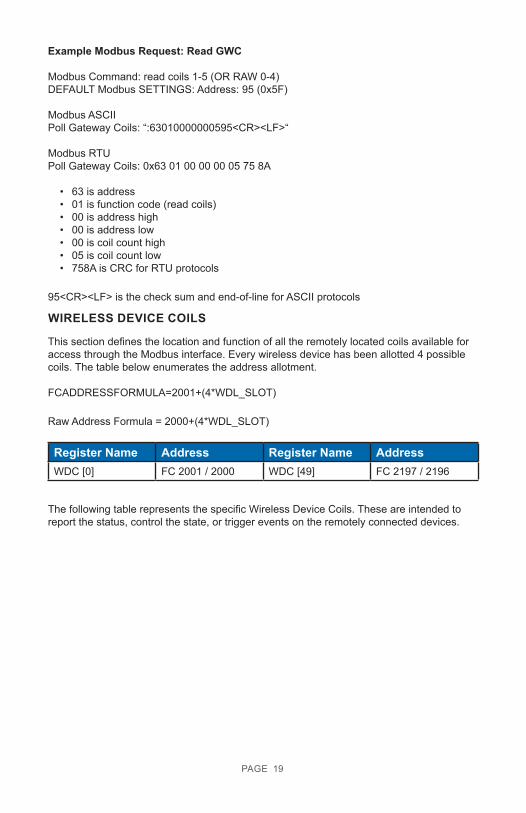
WIRELESS DEVICE COILS
This section defines the location and function of all the remotely located coils available for access through the Modbus interface. Every wireless device has been allotted 4 possible coils. The table below enumerates the address allotment.
FCADDRESSFORMULA=2001+(4*WDL_SLOT)
Raw Address Formula = 2000+(4*WDL_SLOT)
Register Name Address Register Name AddressWDC [0] FC 2001 / 2000 WDC [49] FC 2197 / 2196
The following table represents the specific Wireless Device Coils. These are intended to report the status, control the state, or trigger events on the remotely connected devices.
PAGE 19
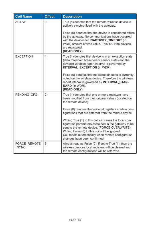
Coil Name Offset DescriptionACTIVE 0 True (1) denotes that the remote wireless device is
actively synchronized with the gateway.
False (0) denotes that the device is considered offline by the gateway. No communications have occurred with the devices for INACTIVITY_TIMEOUT (in WDR) amount of time value. This is 0 if no devices are registered.(READ ONLY)
EXCEPTION 1 True (1) denotes that device is in an exception state (data threshold breached or sensor state) and the device’s wireless report interval is governed by INTERVAL_EXCEPTION (in WDR).
False (0) denotes that no exception state is currently noted on the wireless device. Therefore the wireless report interval is governed by INTERVAL_STAN-DARD (in WDR). (READ ONLY)
PENDING_CFG 2 True (1) denotes that one or more registers have been modified from their original values (located on the remote device).
False (0) denotes that no local registers contain con-figurations that are different from the remote device.
Writing True (1) to this coil will cause the local con-figuration parameters contained in the gateway to be sent to the remote device. (FORCE OVERWRITE). Writing False (0) to this coil will be ignored.Coil resets automatically when remote configuration changes have been confirmed.
PAGE 20
FORCE_REMOTE _SYNC
3 Always read as False (0). If set to True (1), then the wireless devices local registers will be cleared and the remote configurations will be retrieved.
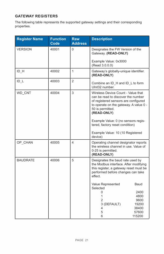
GATEWAY REGISTERSThe following table represents the supported gateway settings and their corresponding properties.
Register Name Function Code
Raw Address
Description
VERSION 40001 0 Designates the FW Version of the Gateway. (READ-ONLY)
Example Value: 0x3000(Read 3.0.0.0)
ID_H 40002 1 Gateway’s globally-unique identifier.(READ-ONLY)
Combine an ID_H and ID_L to form UInt32 number.
ID_L 40003 2
WD_CNT 40004 3 Wireless Device Count - Value that can be read to discover the number of registered sensors are configured to operate on the gateway. A value 0 - 50 is permitted.(READ-ONLY) Example Value: 0 (no sensors regis-tered, factory reset condition)
Example Value: 10 (10 Registered device)
OP_CHAN 40005 4 Operating channel designator reports the wireless channel in use. Value of 0-25 is permitted.(READ-ONLY)
BAUDRATE 40006 5 Designates the baud rate used by the Modbus interface. After modifying this register, a gateway reset must be performed before changes can take effect.
Value Represented BaudSelected 0 2400 1 4800 2 9600 3 (DEFAULT) 19200 4 38400 5 57600 6 115200
PAGE 21
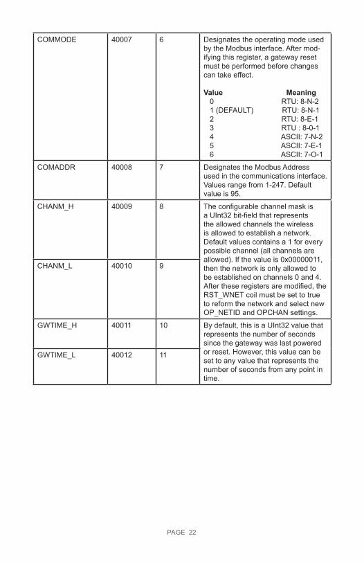
COMMODE 40007 6 Designates the operating mode used by the Modbus interface. After mod-ifying this register, a gateway reset must be performed before changes can take effect.
Value Meaning 0 RTU: 8-N-2 1 (DEFAULT) RTU: 8-N-1 2 RTU: 8-E-1 3 RTU : 8-0-1 4 ASCII: 7-N-2 5 ASCII: 7-E-1 6 ASCII: 7-O-1
COMADDR 40008 7 Designates the Modbus Address used in the communications interface. Values range from 1-247. Default value is 95.
CHANM_H 40009 8 The configurable channel mask is a UInt32 bit-field that represents the allowed channels the wireless is allowed to establish a network. Default values contains a 1 for every possible channel (all channels are allowed). If the value is 0x00000011, then the network is only allowed to be established on channels 0 and 4. After these registers are modified, the RST_WNET coil must be set to true to reform the network and select new OP_NETID and OPCHAN settings.
CHANM_L 40010 9
GWTIME_H 40011 10 By default, this is a UInt32 value that represents the number of seconds since the gateway was last powered or reset. However, this value can be set to any value that represents the number of seconds from any point in time.
GWTIME_L 40012 11
PAGE 22
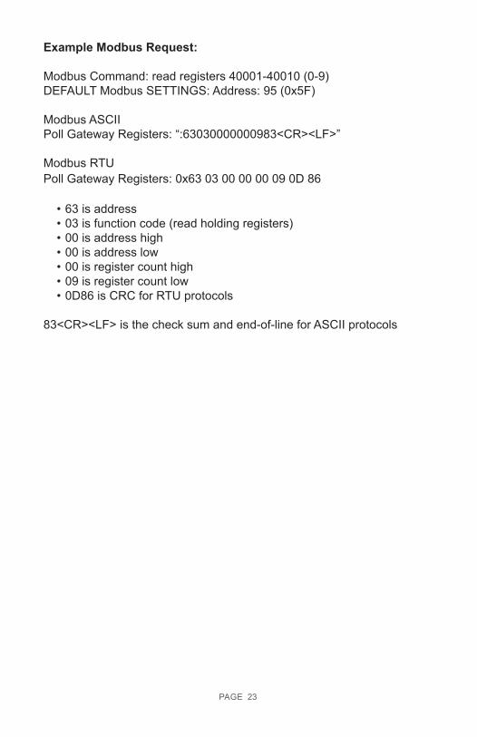
Example Modbus Request:
Modbus Command: read registers 40001-40010 (0-9)DEFAULT Modbus SETTINGS: Address: 95 (0x5F)
Modbus ASCIIPoll Gateway Registers: “:63030000000983<CR><LF>”
Modbus RTUPoll Gateway Registers: 0x63 03 00 00 00 09 0D 86
• 63 is address• 03 is function code (read holding registers)• 00 is address high• 00 is address low• 00 is register count high• 09 is register count low• 0D86 is CRC for RTU protocols
83<CR><LF> is the check sum and end-of-line for ASCII protocols
PAGE 23
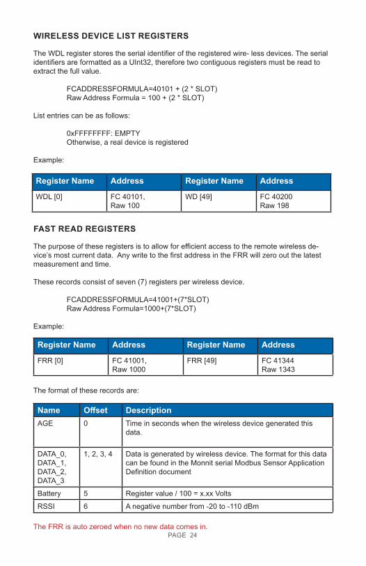
WIRELESS DEVICE LIST REGISTERS
The WDL register stores the serial identifier of the registered wire- less devices. The serial identifiers are formatted as a UInt32, therefore two contiguous registers must be read to extract the full value.
FCADDRESSFORMULA=40101 + (2 * SLOT) Raw Address Formula = 100 + (2 * SLOT)
List entries can be as follows:
0xFFFFFFFF: EMPTY Otherwise, a real device is registered
Example:
Register Name Address Register Name Address
WDL [0] FC 40101,Raw 100
WD [49] FC 40200Raw 198
FAST READ REGISTERS
The purpose of these registers is to allow for efficient access to the remote wireless de-vice’s most current data. Any write to the first address in the FRR will zero out the latest measurement and time.
These records consist of seven (7) registers per wireless device. FCADDRESSFORMULA=41001+(7*SLOT) Raw Address Formula=1000+(7*SLOT)
Example:
Register Name Address Register Name Address
FRR [0] FC 41001,Raw 1000
FRR [49] FC 41344Raw 1343
The format of these records are:
Name Offset DescriptionAGE 0 Time in seconds when the wireless device generated this
data.
DATA_0,DATA_1,DATA_2,DATA_3
1, 2, 3, 4 Data is generated by wireless device. The format for this data can be found in the Monnit serial Modbus Sensor Application Definition document
Battery 5 Register value / 100 = x.xx Volts
RSSI 6 A negative number from -20 to -110 dBm
The FRR is auto zeroed when no new data comes in.PAGE 24
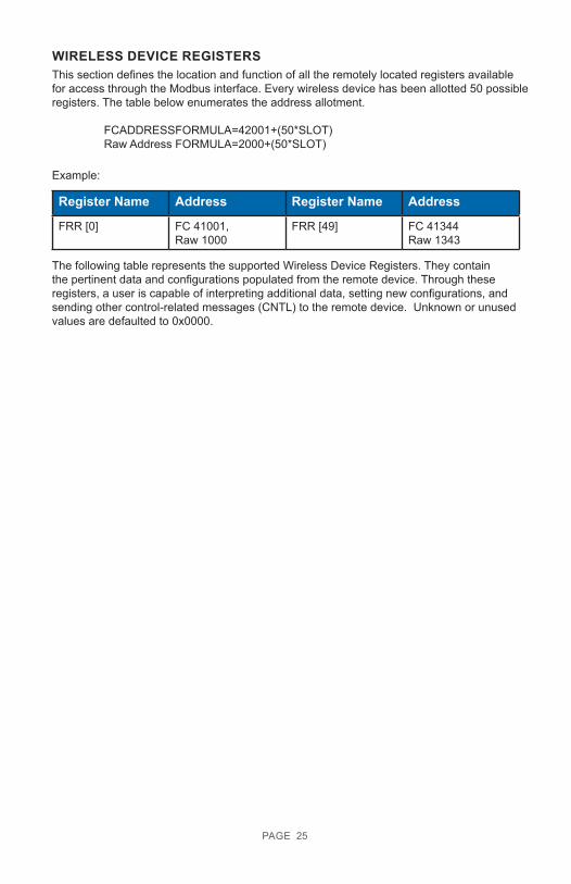
WIRELESS DEVICE REGISTERSThis section defines the location and function of all the remotely located registers available for access through the Modbus interface. Every wireless device has been allotted 50 possible registers. The table below enumerates the address allotment.
FCADDRESSFORMULA=42001+(50*SLOT) Raw Address FORMULA=2000+(50*SLOT)
Example:
Register Name Address Register Name Address
FRR [0] FC 41001,Raw 1000
FRR [49] FC 41344Raw 1343
The following table represents the supported Wireless Device Registers. They contain the pertinent data and configurations populated from the remote device. Through these registers, a user is capable of interpreting additional data, setting new configurations, and sending other control-related messages (CNTL) to the remote device. Unknown or unused values are defaulted to 0x0000.
PAGE 25
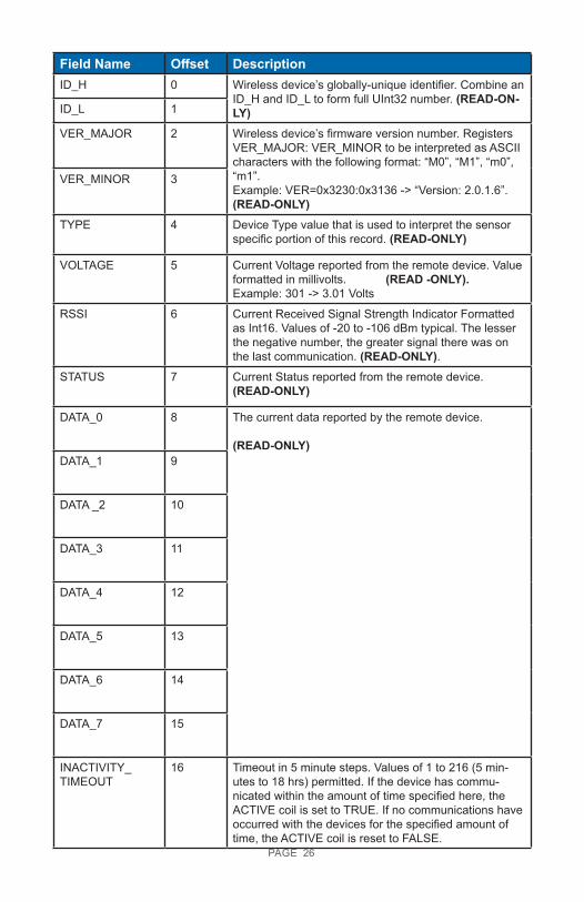
Field Name Offset DescriptionID_H 0 Wireless device’s globally-unique identifier. Combine an
ID_H and ID_L to form full UInt32 number. (READ-ON-LY)ID_L 1
VER_MAJOR 2 Wireless device’s firmware version number. Registers VER_MAJOR: VER_MINOR to be interpreted as ASCII characters with the following format: “M0”, “M1”, “m0”, “m1”. Example: VER=0x3230:0x3136 -> “Version: 2.0.1.6”. (READ-ONLY)
VER_MINOR 3
TYPE 4 Device Type value that is used to interpret the sensor specific portion of this record. (READ-ONLY)
VOLTAGE 5 Current Voltage reported from the remote device. Value formatted in millivolts. (READ -ONLY). Example: 301 -> 3.01 Volts
RSSI 6 Current Received Signal Strength Indicator Formatted as Int16. Values of -20 to -106 dBm typical. The lesser the negative number, the greater signal there was on the last communication. (READ-ONLY).
STATUS 7 Current Status reported from the remote device. (READ-ONLY)
DATA_0 8 The current data reported by the remote device.
(READ-ONLY) DATA_1 9
DATA _2 10
DATA_3 11
DATA_4 12
DATA_5 13
DATA_6 14
DATA_7 15
INACTIVITY_ TIMEOUT
16 Timeout in 5 minute steps. Values of 1 to 216 (5 min-utes to 18 hrs) permitted. If the device has commu-nicated within the amount of time specified here, the ACTIVE coil is set to TRUE. If no communications have occurred with the devices for the specified amount of time, the ACTIVE coil is reset to FALSE.
PAGE 26
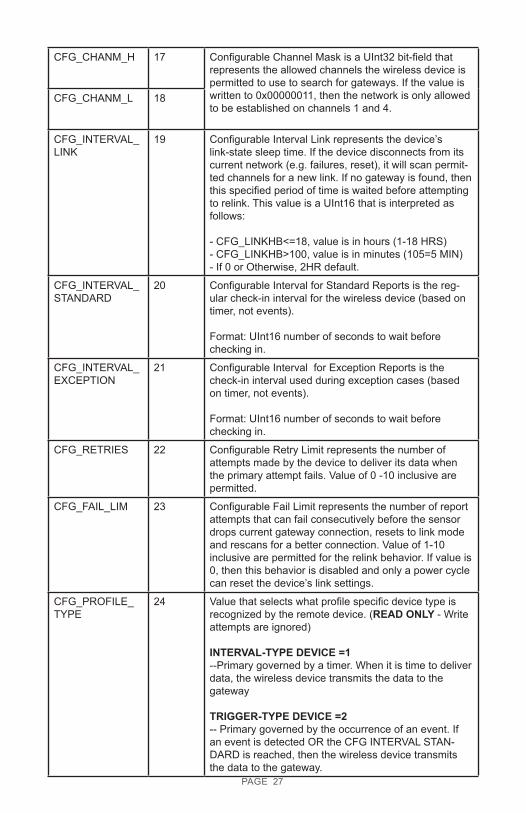
CFG_CHANM_H 17 Configurable Channel Mask is a UInt32 bit-field that represents the allowed channels the wireless device is permitted to use to search for gateways. If the value is written to 0x00000011, then the network is only allowed to be established on channels 1 and 4.
CFG_CHANM_L 18
CFG_INTERVAL_ LINK
19 Configurable Interval Link represents the device’s link-state sleep time. If the device disconnects from its current network (e.g. failures, reset), it will scan permit-ted channels for a new link. If no gateway is found, then this specified period of time is waited before attempting to relink. This value is a UInt16 that is interpreted as follows:
- CFG_LINKHB<=18, value is in hours (1-18 HRS)- CFG_LINKHB>100, value is in minutes (105=5 MIN)- If 0 or Otherwise, 2HR default.
CFG_INTERVAL_ STANDARD
20 Configurable Interval for Standard Reports is the reg-ular check-in interval for the wireless device (based on timer, not events).
Format: UInt16 number of seconds to wait before checking in.
CFG_INTERVAL_ EXCEPTION
21 Configurable Interval for Exception Reports is the check-in interval used during exception cases (based on timer, not events).
Format: UInt16 number of seconds to wait before checking in.
CFG_RETRIES 22 Configurable Retry Limit represents the number of attempts made by the device to deliver its data when the primary attempt fails. Value of 0 -10 inclusive are permitted.
CFG_FAIL_LIM 23 Configurable Fail Limit represents the number of report attempts that can fail consecutively before the sensor drops current gateway connection, resets to link mode and rescans for a better connection. Value of 1-10 inclusive are permitted for the relink behavior. If value is 0, then this behavior is disabled and only a power cycle can reset the device’s link settings.
CFG_PROFILE_ TYPE
24 Value that selects what profile specific device type is recognized by the remote device. (READ ONLY - Write attempts are ignored)
INTERVAL-TYPE DEVICE =1--Primary governed by a timer. When it is time to deliver data, the wireless device transmits the data to the gateway
TRIGGER-TYPE DEVICE =2-- Primary governed by the occurrence of an event. If an event is detected OR the CFG INTERVAL STAN-DARD is reached, then the wireless device transmits the data to the gateway.
PAGE 27
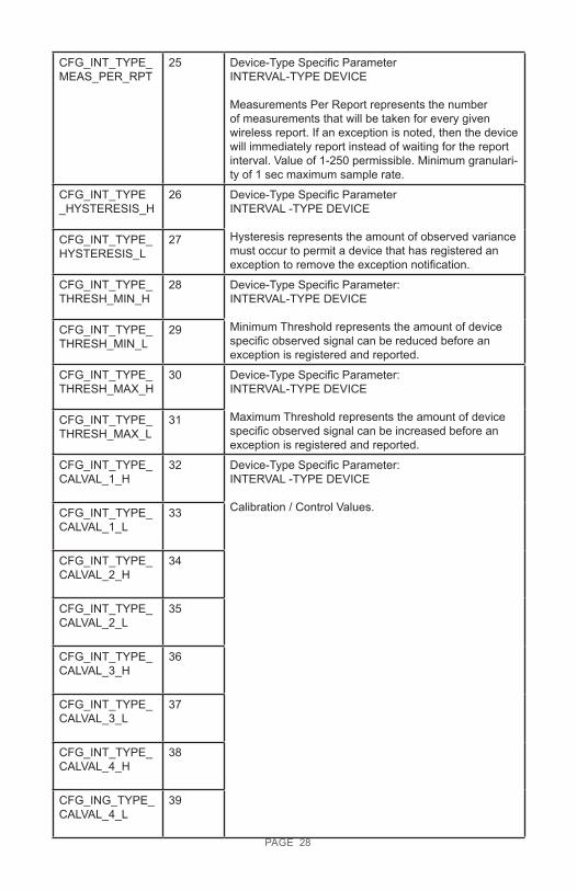
CFG_INT_TYPE_ MEAS_PER_RPT
25 Device-Type Specific ParameterINTERVAL-TYPE DEVICE
Measurements Per Report represents the number of measurements that will be taken for every given wireless report. If an exception is noted, then the device will immediately report instead of waiting for the report interval. Value of 1-250 permissible. Minimum granulari-ty of 1 sec maximum sample rate.
CFG_INT_TYPE _HYSTERESIS_H
26 Device-Type Specific ParameterINTERVAL -TYPE DEVICE
Hysteresis represents the amount of observed variance must occur to permit a device that has registered an exception to remove the exception notification.
CFG_INT_TYPE_ HYSTERESIS_L
27
CFG_INT_TYPE_THRESH_MIN_H
28 Device-Type Specific Parameter:INTERVAL-TYPE DEVICE
Minimum Threshold represents the amount of device specific observed signal can be reduced before an exception is registered and reported.
CFG_INT_TYPE_ THRESH_MIN_L
29
CFG_INT_TYPE_ THRESH_MAX_H
30 Device-Type Specific Parameter:INTERVAL-TYPE DEVICE
Maximum Threshold represents the amount of device specific observed signal can be increased before an exception is registered and reported.
CFG_INT_TYPE_THRESH_MAX_L
31
CFG_INT_TYPE_ CALVAL_1_H
32 Device-Type Specific Parameter:INTERVAL -TYPE DEVICE
Calibration / Control Values. CFG_INT_TYPE_ CALVAL_1_L
33
CFG_INT_TYPE_CALVAL_2_H
34
CFG_INT_TYPE_CALVAL_2_L
35
CFG_INT_TYPE_ CALVAL_3_H
36
CFG_INT_TYPE_CALVAL_3_L
37
CFG_INT_TYPE_ CALVAL_4_H
38
CFG_ING_TYPE_ CALVAL_4_L
39
PAGE 28
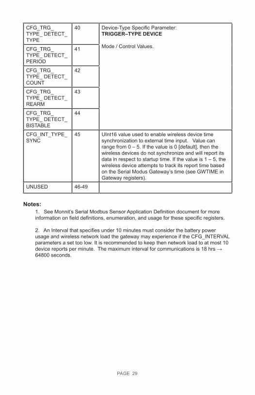
CFG_TRG_TYPE_ DETECT_TYPE
40 Device-Type Specific Parameter: TRIGGER–TYPE DEVICE
Mode / Control Values.CFG_TRG_TYPE_ DETECT_PERIOD
41
CFG_TRG_TYPE_ DETECT_COUNT
42
CFG_TRG_TYPE_ DETECT_REARM
43
CFG_TRG_TYPE_ DETECT_BISTABLE
44
CFG_INT_TYPE_SYNC
45 UInt16 value used to enable wireless device time synchronization to external time input. Value can range from 0 – 5. If the value is 0 [default], then the wireless devices do not synchronize and will report its data in respect to startup time. If the value is 1 – 5, the wireless device attempts to track its report time based on the Serial Modus Gateway’s time (see GWTIME in Gateway registers).
UNUSED 46-49
Notes:1. See Monnit’s Serial Modbus Sensor Application Definition document for more information on field definitions, enumeration, and usage for these specific registers.
2. An Interval that specifies under 10 minutes must consider the battery power usage and wireless network load the gateway may experience if the CFG_INTERVAL parameters a set too low. It is recommended to keep then network load to at most 10 device reports per minute. The maximum interval for communications is 18 hrs → 64800 seconds.
PAGE 29
SUPPORTFor technical support and troubleshooting tips please visit our support library online at monnit.com/support/. If you are unable to solve your issue using our online support, email Monnit support at [email protected] with your contact information and a description of the problem, and a support representative will call you within one business day.
For error reporting, please email a full description of the error to [email protected].
WARRANTY INFORMATION(a) Monnit warrants that Monnit-branded products (Products) will be free from defects in materials and workmanship for a period of one (1) year from the date of delivery with respect to hardware and will materially conform to their published specifications for a period of one (1) year with respect to software. Monnit may resell sensors manufactured by other entities and are subject to their individual warranties; Monnit will not enhance or extend those warranties. Monnit does not warrant that the software or any portion thereof is error free. Monnit will have no warranty obligation with respect to Products subjected to abuse, misuse, negligence or accident. If any software or firmware incorporated in any Product fails to conform to the warranty set forth in this Section, Monnit shall provide a bug fix or software patch correcting such non-conformance within a reasonable period after Monnit receives from customer (i) notice of such non-conformance, and (ii) sufficient information regarding such non-conformance so as to permit Monnit to create such bug fix or software patch. If any hardware component of any Product fails to conform to the warranty in this Section, Monnit shall, at its option, refund the purchase price less any discounts, or repair or replace non-conforming Products with conforming Products, or Products having substan-tially identical form, fit, and function and deliver the repaired or replacement Product to a carrier for land shipment to customer within a reasonable period after Monnit receives from customer (i) notice of such non-conformance, and (ii) the non-conforming Product provided; however, if, in its opinion, Monnit cannot repair or replace on commercially reasonable terms it may choose to refund the purchase price. Repair parts and replacement Products may be reconditioned or new. All replacement Products and parts become the property of Monnit. Repaired or replacement Products shall be subject to the warranty, if any remains, originally applicable to the Product repaired or replaced. Customer must obtain from Monnit a Return Material Authorization Number (RMA) prior to returning any Products to Monnit. Products returned under this Warranty must be unmodified.
Customer may return all Products for repair or replacement due to defects in original materials and workmanship if Monnit is notified within one year of customer’s receipt of the Product. Monnit reserves the right to repair or replace Products at its own and complete discretion. Customer must obtain from Monnit a Return Material Authorization Number (RMA) prior to returning any Products to Monnit. Products returned under this Warranty must be unmodified and in original packaging. Monnit reserves the right to refuse warran-ty repairs or replacements for any Products that are damaged or not in original form. For Products outside the one year warranty period repair services are available at Monnit at standard labor rates for a period of one year from the customer’s original date of receipt.
(b) As a condition to Monnit’s obligations under the immediately preceding paragraphs, cus-tomer shall return Products to be examined and replaced to Monnit’s facilities, in shipping cartons which clearly display a valid RMA number provided by Monnit. Customer acknowl-edges that replacement products may be repaired, refurbished or tested and found to be complying. Customer shall bear the risk of loss for such return shipment and shall bear all shipping costs. Monnit shall deliver replacements for Products determined by Monnit to be properly returned, shall bear the risk of loss and such costs of shipment of repaired Products or replacements, and shall credit customer’s reasonable costs of shipping such returned Products against future purchases.
PAGE 30

(c) Monnit’s sole obligation under the warranty described or set forth here shall be to repair or replace non-conforming products as set forth in the immediately preceding paragraph, or to refund the documented purchase price for non-conforming Products to customer. Mon-nit’s warranty obligations shall run solely to customer, and Monnit shall have no obligation to customers of customer or other users of the Products.
Limitation of Warranty and Remedies.
THE WARRANTY SET FORTH HEREIN IS THE ONLY WARRANTY APPLICABLE TO PRODUCTS PURCHASED BY CUSTOMER. ALL OTHER WARRANTIES, EXPRESS OR IMPLIED, INCLUDING BUT NOT LIMITED TO THE IMPLIED WARRANTIES OF MERCHANTABILITY AND FITNESS FOR A PARTICULAR PURPOSE ARE EXPRESSLY DISCLAIMED. MONNIT’S LIABILITY WHETHER IN CONTRACT, IN TORT, UNDER ANY WARRANTY, IN NEGLIGENCE OR OTHERWISE SHALL NOT EXCEED THE PURCHASE PRICE PAID BY CUSTOMER FOR THE PRODUCT. UNDER NO CIRCUMSTANCES SHALL MONNIT BE LIABLE FOR SPECIAL, INDIRECT OR CONSEQUENTIAL DAMAG-ES. THE PRICE STATED FOR THE PRODUCTS IS A CONSIDERATION IN LIMITING MONNIT’S LIABILITY. NO ACTION, REGARDLESS OF FORM, ARISING OUT OF THIS AGREEMENT MAY BE BROUGHT BY CUSTOMER MORE THAN ONE YEAR AFTER THE CAUSE OF ACTION HAS ACCRUED.
IN ADDITION TO THE WARRANTIES DISCLAIMED ABOVE, MONNIT SPECIFICALLY DISCLAIMS ANY AND ALL LIABILITY AND WARRANTIES, IMPLIED OR EXPRESSED, FOR USES REQUIRING FAIL-SAFE PERFORMANCE IN WHICH FAILURE OF A PROD-UCT COULD LEAD TO DEATH, SERIOUS PERSONAL INJURY, OR SEVERE PHYSICAL OR ENVIRONMENTAL DAMAGE SUCH AS, BUT NOT LIMITED TO, LIFE SUPPORT OR MEDICAL DEVICES OR NUCLEAR APPLICATIONS. PRODUCTS ARE NOT DESIGNED FOR AND SHOULD NOT BE USED IN ANY OF THESE APPLICATIONS.
PAGE 31
CERTIFICATIONS
United States FCC
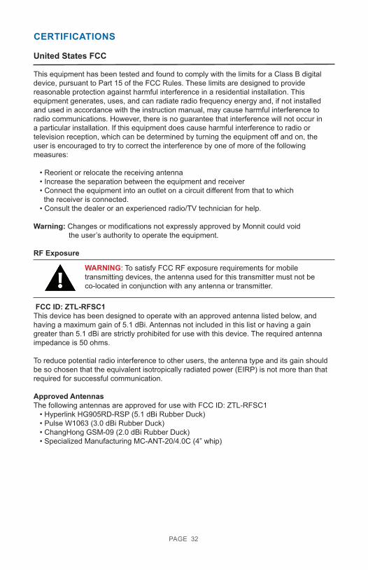
This equipment has been tested and found to comply with the limits for a Class B digital device, pursuant to Part 15 of the FCC Rules. These limits are designed to provide reasonable protection against harmful interference in a residential installation. This equipment generates, uses, and can radiate radio frequency energy and, if not installed and used in accordance with the instruction manual, may cause harmful interference to radio communications. However, there is no guarantee that interference will not occur in a particular installation. If this equipment does cause harmful interference to radio or television reception, which can be determined by turning the equipment off and on, the user is encouraged to try to correct the interference by one of more of the following measures:
• Reorient or relocate the receiving antenna • Increase the separation between the equipment and receiver • Connect the equipment into an outlet on a circuit different from that to which the receiver is connected. • Consult the dealer or an experienced radio/TV technician for help.
Warning: Changes or modifications not expressly approved by Monnit could void the user’s authority to operate the equipment.
RF Exposure
FCC ID: ZTL-RFSC1This device has been designed to operate with an approved antenna listed below, and having a maximum gain of 5.1 dBi. Antennas not included in this list or having a gain greater than 5.1 dBi are strictly prohibited for use with this device. The required antenna impedance is 50 ohms.
To reduce potential radio interference to other users, the antenna type and its gain should be so chosen that the equivalent isotropically radiated power (EIRP) is not more than that required for successful communication.
Approved AntennasThe following antennas are approved for use with FCC ID: ZTL-RFSC1 • Hyperlink HG905RD-RSP (5.1 dBi Rubber Duck) • Pulse W1063 (3.0 dBi Rubber Duck) • ChangHong GSM-09 (2.0 dBi Rubber Duck) • Specialized Manufacturing MC-ANT-20/4.0C (4” whip)
WARNING: To satisfy FCC RF exposure requirements for mobile transmitting devices, the antenna used for this transmitter must not be co-located in conjunction with any antenna or transmitter.
PAGE 32
Canada (IC)
EnglishUnder Industry Canada regulations, this radio transmitter may only operate using an anten-na of a type and maximum (or lesser) gain approved for the transmitter by Industry Canada. To reduce potential radio interference to other users, the antenna type and its gain should be so chosen that the equivalent isotropically radiated power (e.i.r.p.) is not more than that necessary for successful communication.
This radio transmitter (IC: 9794A-RFSC1) has been approved by Industry Canada to op-erate with the antenna types listed below with the maximum permissible gain and required antenna impedance for each antenna type indicated. Antenna types not included in this list, having a gain greater than the maximum gain indicated for that type, are strictly prohibited for use with this device.
This device complies with Industry Canada license-exempt RSS standard(s). Operation is subject to the following two conditions: (1) this device may not cause interference, and (2) this device must accept any interference, including interference that may cause undesired operation of the device.
FrenchConformément à la réglementation d’Industrie Canada, le présent émetteur radio peut fonctionner avec une antenne d’un type et d’un gain maximal (ou inférieur) approuvé pour l’émetteur par Industrie Canada. Dans le but de réduire les risques de brouillage radioélec-trique à l’intention des autres utilisateurs, il faut choisir le type d’antenne et son gain de sorte que la puissance isotrope rayonnée équivalente (p.i.r.e.) ne dépasse pas l’intensité nécessaire à l’établissement d’une communication satisfaisante.
Le présent émetteur radio (IC: 9794A-RFSC1) a été approuvé par Industrie Canada pour fonctionner avec les types d’antenne énumérés ci-dessous et ayant un gain admissible maximal et l’impédance requise pour chaque type d’antenne. Les types d’antenne non inclus dans cette liste, ou dont le gain est supérieur au gain maximal indiqué, sont stricte-ment interdits pour l’exploitation de l’émetteur.
Le présent appareil est conforme aux CNR d’Industrie Canada applicables aux appareils radio exempts de licence. L’exploitation est autorisée aux deux conditions suivantes : (1) l’appareil ne doit pas produire de brouillage, et (2) l’utilisateur de l’appareil doit accepter tout brouillage radioélectrique subi, méme si le brouillage est susceptible d’en comprom-ettre le fonctionnement.
PAGE 33

For additional information on Monnit Wireless Sensors and Software, please visit us on the web at www.monnit.com.
Monnit Corporation3400 South West TempleSalt Lake City, UT 84115801-561-5555www.monnit.com
Monnit, Monnit Logo and all other trademarks are property of Monnit, Corp. © 2019 Monnit Corp. All Rights Reserved.
AUG-009 (01/19)