Embed Size (px)
Citation preview
User-Service ManualJoerns® Camtec Series Bed Frames
RC 1000 BedExpandable Split-frame Bariatric Bed
Model RC1000To avoid injury, read user’s manual before using.
The Caregiver’s Choice
TM

2
Joerns® Camtec Series Bed FramesRC 1000 Bed
© 2016 Joerns Healthcare • 6110284 RevB • 16-2016
Important Precautions
Caution: Rotating parts. Keep fingers and arms clear of bed when mechanism is moving.
Caution: Pinch points. Keep objects away from these areas while bed is in motion.
Caution: Electrical hazard may occur if bed is plugged into inadequate power supply. Make sure to use a 115 volt, 3 prong, grounded outlet with a capacity of at least 15 amps.
Caution: Keep feet clear of casters. Make sure casters are locked before transferring patients.
Caution: Make sure that the cords from the control module and pendant are properly positioned before operating the bed. Do not allow either cord to get caught in the moving parts of the bed.
Caution: When using a turning mattress, make sure there is a bolster between the mattress and side rail.
Warning: Keep all objects out from under bed. Certain parts under the bed raise and lower when the bed is in motion.
Warning: Do not place arms or head into frame while operating. Stand clear of the bed frame before operating.
Warning: Do not operate this device if the power cord or any of the cords coming from the control module are cut, frayed, damaged or loosely connected.
Warning: Do not service the bed without first disconnecting the power cord.
Warning: The bed must be unplugged from the wall socket prior to using the emergency crank. Failure to do so may result in damage to the bed and injury to the personnel using the crank.
Warning: ESD - electrostatic discharge.
Warning: The bed should be left in the lowest position when unattended in order to reduce the risk of injury due to falls while getting into or out of bed, or while lying on the bed.
Warning: When raising or lowering bed, casters at the foot end should be in the steer position. Head end should be free to move.
Warning: Possible Fire Hazard. Use nasal mask or ½ bed tent oxygen administering equipment. Oxygen tent should not extend below mattress support platform. Pendant should not be placed in an oxygen enriched environment such as an oxygen tent. Use of electrical circuits in an oxygen-enriched environment could result in a fire hazard.
Warning: Possible Injury Or Death. An optimal bed system assessment should be conducted on each resident by a qualified clinician or medical provider to ensure maximum safety of the resident. The assessment should be conducted within the context of, and in compliance with, the state and federal guidelines related to the use of restraints and bed system entrapment guidance, including the Clinical Guidance for the Assessment and Implementation of Side Rails published by the Hospital Bed Safety Workgroup of the U.S. Food and Drug Administration. Further information can be obtained at the following web address: http://www.fda.gov/MedicalDevices/ProductsandMedicalProcedures/GeneralHospitalDevicesandSupplies/HospitalBeds/default.htm.
Warning: Possible Injury Or Death. Use a properly sized mattress in order to minimize the gap between the side of mattress and Side Rails/Assist Devices. This gap must be small enough to prevent resident/ patient from getting his/her head or neck caught in this location. Make sure that raising or lowering bed, or contouring the mattress support platform, does not create any hazardous gaps. Excessive gaps may result in injury or death.
Warning: Possible Injury Or Death. Residents/ patients may become entangled in pendant cord. Patients with reduced mental acuity should not be allowed access to pendant. Unsupervised use of pendant could result in injury or death.
Caution: Before transporting bed, unplug bed from power source, secure Power Cord on cord storage straps on Head Panel and hang Pendant from Head Panel. Failure to do so could result in Power Cord, pendant cord, or bed damage, thereby creating a potential hazard.
Caution: Extend all four sections on each side prior to adjusting bed position or side rails.
Warning: Use Width Extenders only after the resident/ patient is safely positioned in the bed. Failure to do so could result in injury.
3
Joerns® Camtec Series Bed FramesRC 1000 Bed
© 2016 Joerns Healthcare • 6110284 RevB • 16-2016
Caution: Drainage Bag Loops are not intended for use as tie downs.
Warning: Possible Injury Or Death. Bed safe working load is 1000 pounds. This is total weight counting resident/patient, mattress, bedding and any other equipment or persons likely to be on bed. Do not exceed 1000-pound safe working load. Exceeding the safe working load could result in property damage, injury or death.
Warning: Possible Injury Or Death. Do not use any Side Rails/Assist Devices until you verify they are locked in place. Failure to lock assist devices may result in injury or death.
Notice: Make sure the power cord is unplugged from the power outlet prior to disconnecting/connecting any foot panel cables. Failure to ensure bed is not powered when disconnecting/connecting the foot panel cables may result in damage to the bed’s electronic controls.
Warning: Possible Injury Or Death. If using accessories not manufactured, marketed, or provided by Joerns Healthcare for Camtec beds, consult with the manufacturer for compatibility and limitations prior to use. Failure to do so may result in injury or death.
Bed System Entrapment Information
In April 1999, the U.S. Food and Drug Administration (FDA) in partnership with representatives from the hospital and post-acute bed industry, including Joerns Healthcare, national healthcare organizations, resident advocacy groups, and other federal agencies formed the Hospital Bed Safety Workgroup (HBSW). The workgroup’s goal is to improve the safety of bed frames for patients and residents in all health care settings who are most vulnerable to the risk of entrapment. The efforts of the FDA and the HBSW culminated in the FDA’s release of recommended guidelines intended to reduce the risk of entrapment, including dimensional limits for critical gaps and spaces between bed system components and clinical guidance for assessment and implementation of bed side rails in various health care settings.
Entrapment zones involve the relationship of bed components often directly assembled by the healthcare facility rather than the manufacturer. Therefore, compliance is the responsibility of the facility.
As the leading manufacturer of long-term care beds and a frontrunner in addressing this critical issue, Joerns Healthcare can offer you the expertise, assistance and products to bring your facility into compliance.
Joerns® Compliance Solutions
Matching the right bed components in order to meet regulatory guidelines can be complex.
That is why Joerns offers a wide array of compliance options. We assist customers in selecting compliant accessories recommended for their specific bed model.
For More Information
To learn more about compliance options with Joerns products, visit our website at www.joerns.com, or contact our Customer Care reps at 800-826-0270 and ask for free informational publications.
To learn more about entrapment zones, assessment methods and guidelines concerning entrapment, contact Joerns Healthcare at 800-826-0270 or consult the FDA website: http://www.fda.gov/MedicalDevices/ProductsandMedicalProcedures/GeneralHospitalDevicesandSupplies/HospitalBeds/default.htm.
4
Joerns® Camtec Series Bed FramesRC 1000 Bed
© 2016 Joerns Healthcare • 6110284 RevB • 16-2016
Table of ContentsImportant Precautions .................................................................................................................2Entrapment Information ...............................................................................................................3Introduction ..................................................................................................................................4Specifications ..............................................................................................................................5Assembly .....................................................................................................................................6Operation .....................................................................................................................................7Cleaning and Maintenance ..........................................................................................................8Troubleshooting ...........................................................................................................................9Customer Maintenance Checklist ..............................................................................................10Appendix A.................................................................................................................................12Accessories: Scale Instructions .................................................................................................23Warranty ....................................................................................................................................26
Introduction
The Joerns Camtec Series RC 1000 Bed has been designed primarily for use in hospitals and other institutions to support patients whose weight exceeds the limit of conventional beds and who may require special positioning. The frame has a long history as the Camtec model 4475-0 supporting care of some of the most challenging patients presented within the care continuum. The unique expandable frame design allows the bed to accommodate support surfaces of up to 54" wide. The bed surface can be adjusted to allow it to pass through a 40" door opening.
The frame is constructed of structural steel. The frames lowest position is approximately 16½" from the floor to the mattress support platform. The frame in the highest position is approximately 29".
The frame is designed to support a safe working load of 1000 lbs. Side rails at the head end are standard. Optionally, the bed can be equipped with foot end side rails and side rail pads. The 45 degree angle setting of the side rails assists in patient ingress and egress.
The trapeze is an available option using a full-frame design purpose built to support bariatric patients for this type of bed and allow convenient adjustability for repositioning. The bed is equipped with (3) locking swivel casters and (1) steering swivel caster to allow for easy bed movement and facilitate bed transport.
The bed contains four electric drive modules, one for the head, one for the knee, one Hi/Lo for the head end and one Hi/Lo for the foot end of the bed. A hand crank is supplied at the head end of the bed that can be used in the event of a power failure.
5
Joerns® Camtec Series Bed FramesRC 1000 Bed
© 2016 Joerns Healthcare • 6110284 RevB • 16-2016
Specifications
Safe Working Load .................. 1000 lbsOverall Width ........................... 39½" expandable to 56½"Overall Length ......................... 89"Mattress Support Platform ..... Width: Adjustable 36", 40", 42", 48", and 54" Length: 80"Mattress Support Platform Height ..... Lowest position (from floor) 16½" Highest position 29"
Power Requirements ............... 115 VAC 60Hz 10.5 AMP
Operating ConditionsAmbient Temperature .............. +10°C to +30°CRelative Humidity .................... 30% to 95% Non-CondensingAtmospheric Pressure ............ 700 hPa to 1060 hPa
Storage and Shipping ConditionsAmbient Temperature .............. -30°C to +50°C RelativeHumidity ................................... 10% to 95%Atmospheric Pressure ............ 500 hPa to 1060 hPa
Bed Weight with Side Rails, End Boards ........ 610 lbs.
Motor Duty Cycle for Intermittent Operation .. 1 minute ON / 10 minutes OFF
Head Fowler ............................. Adjustable up to 70 degreesFoot/Knee Gatch ...................... Adjustable up to 40 degrees
Side Rails ................................. Head end are standard, 3 position swing type
Casters ..................................... Diameter 5" ...... Width 1¼" (3) total lock and (1) steer lock Tread Guards ... Non-marring
Options .................................... Trapeze Mattress Foot Extension Side rails, foot end Pads or Composite Insert for Side Rails Integrated Scale
6
Joerns® Camtec Series Bed FramesRC 1000 Bed
© 2016 Joerns Healthcare • 6110284 RevB • 16-2016
Assembly
Disassembly of the split frame for mobility
Warning: Lock casters when cleaning, inspecting or performing any maintenance on the bed. Lower all mattress support platform sections unless necessary for service access.
1. When transferring the patient into or out of the bed all four casters should be in the locked position.2. Disconnect the power cord from the wall outlet. Lock all casters.3. Remove the footboard from the outward most sockets. If this is a scale model, disconnect the two leads from the
bed to the readout. 4. Remove the headboard from the inward most sockets. The power cord may be removed from the power cord
hanger as needed.5. The pendant should remain with the head end of bed. If it becomes necessary to unplug the pendant, squeeze
the release levers on either side of the plug, and then gently remove the plug.6. Disconnect the electrical cables between the two halves at the center point of the frame. A set of red-banded
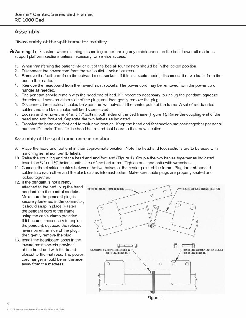
cables and the black cables will be disconnected.7. Loosen and remove the ⅜" and ½" bolts in both sides of the bed frame (Figure 1). Raise the coupling end of the
head end and foot end. Separate the two halves as indicated. 8. Transfer the head and foot end to their new location. Keep the head and foot section matched together per serial
number ID labels. Transfer the head board and foot board to their new location.
Assembly of the split frame once in position
9. Place the head and foot end in their approximate position. Note the head and foot sections are to be used with matching serial number ID labels.
10. Raise the coupling end of the head end and foot end (Figure 1). Couple the two halves together as indicated. Install the ⅜" and ½" bolts in both sides of the bed frame. Tighten nuts and bolts with wrenches.
11. Connect the electrical cables between the two halves at the center point of the frame. Plug the red-banded cables into each other and the black cables into each other. Make sure cable plugs are properly seated and locked together.
12. If the pendant is not already attached to the bed, plug the hand pendant into the control module. Make sure the pendant plug is securely fastened in the connector, it should snap in place. Fasten the pendant cord to the frame using the cable clamp provided. If it becomes necessary to unplug the pendant, squeeze the release levers on either side of the plug, then gently remove the plug.
13. Install the headboard posts in the inward most sockets provided at the head end with the board closest to the mattress. The power cord hanger should be on the side away from the mattress.
Figure 1
7
Joerns® Camtec Series Bed FramesRC 1000 Bed
© 2016 Joerns Healthcare • 6110284 RevB • 16-2016
14. Install the footboard posts in the outward most sockets provided at the foot end with the board facing away. If this is a scale model, connect the two leads from the bed to the readout. One cable connector has 6 prongs while the other has 4 prongs. Make sure the cables are connected to the appropriate connectors.
15. Do a careful walk around inspection of the bed to assure that the two main parts are properly assembled and locked into place using the pins supplied. Look under the bed to make sure nothing is stored there. This area must be kept clear to avoid any interference with parts in motion during bed operation.
16. When raising or lowering the bed, the casters at the foot end should be locked and the casters at the head end should be free to move. If the casters are locked at both ends at the same time, when raising or lowering the bed, permanent damage to the bed may result.
17. Plug the power cord into a grounded 115 volt socket having a capacity of at least 15 amps.18. Using the hand pendant, cycle the bed through all of its operations. Make sure that everyone is clear of the
moving parts during these operations.19. Use this Operation and Maintenance Manual to instruct all personnel who are involved in the use of this
model bed.20. When transferring the patient into or out of the bed all four casters should be in the locked position
Operation
1. When raising or lowering the bed, the casters at the head end should be locked and the casters at the foot end should be in the steer position. If the casters are locked at both ends at the same time, when raising or lowering the bed, damage to the bed may result.
2. Plug the power cord into a grounded 115 volt socket having a capacity of at least 15 amps. Make sure light on control module is illuminated.
3. Using the hand pendant, cycle the bed through all of its operations. Make sure that everyone is clear of the moving parts during these operations.
4. Use this User-Service Manual to instruct all personnel who are involved in the use of this model bed.5. When transferring the patient into or out of the bed all four casters should be in the locked position.6. Width section adjustments are made by pulling tether and sliding out extension.
Caution: Extend all four sections of each side prior to adjusting bed position or side rails.
7. Operate side rail pulling the handle at the middle-top of the rail and rotating rail upward to ensure locked in place in up position. The rail can be rotated outward at a 45 degrees for access to the patient or during lateral rotation. The rail can be rotated down for egress from the bed.
Notice: Make sure the power cord is unplugged from the power outlet prior to disconnecting/connecting any foot panel cables. Failure to ensure bed is not powered when disconnecting/connecting the foot panel cables may result in damage to the bed’s electronic controls.
Casters
The bed is equipped with (4) locking casters consisting of (3) total lock and (1) steer lock. The steer lock caster is located on the left foot position and will lock the direction of the caster inline (end to end) with the bed when activated. This allows for better control when transporting the bed. For best control the bed should be pushed or pulled from the head end.
Never lock casters at both ends at the same time, when raising or lowering the bed, as permanent damage to the bed may result. All casters should be locked during ingress or egress of patient.
8
Joerns® Camtec Series Bed FramesRC 1000 Bed
© 2016 Joerns Healthcare • 6110284 RevB • 16-2016
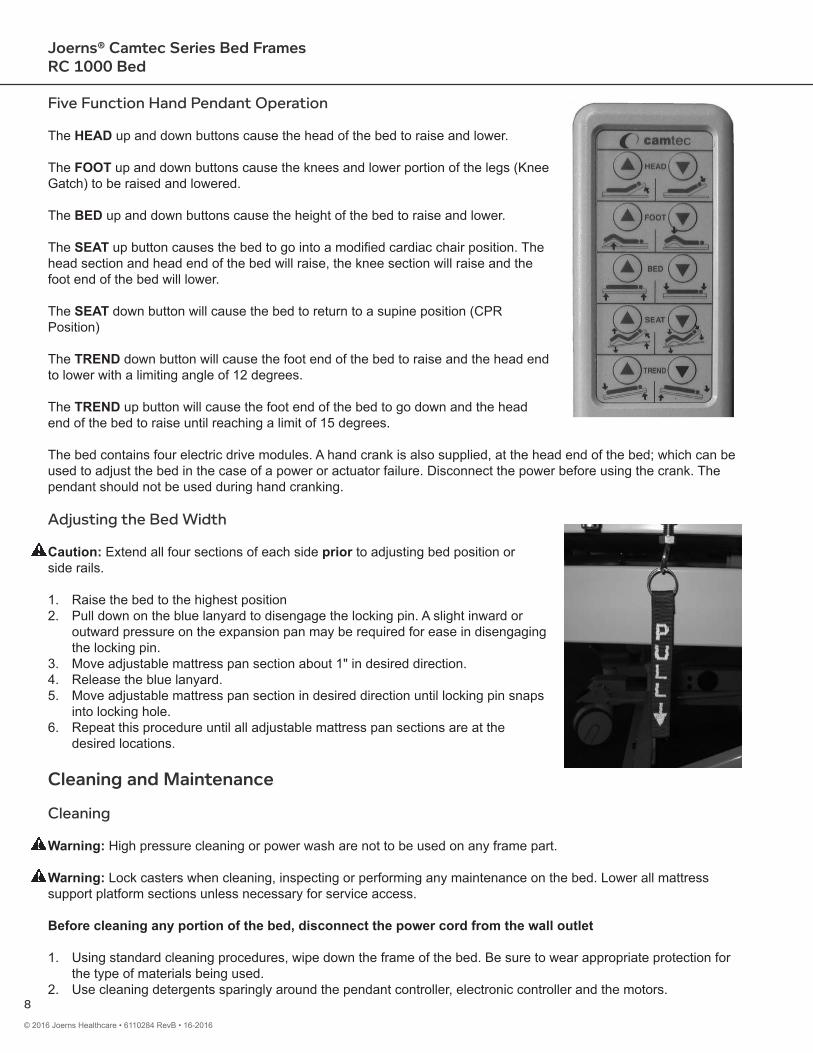
Five Function Hand Pendant Operation
The HEAD up and down buttons cause the head of the bed to raise and lower.
The FOOT up and down buttons cause the knees and lower portion of the legs (Knee Gatch) to be raised and lowered.
The BED up and down buttons cause the height of the bed to raise and lower.
The SEAT up button causes the bed to go into a modified cardiac chair position. The head section and head end of the bed will raise, the knee section will raise and the foot end of the bed will lower.
The SEAT down button will cause the bed to return to a supine position (CPR Position)
The TREND down button will cause the foot end of the bed to raise and the head end to lower with a limiting angle of 12 degrees.
The TREND up button will cause the foot end of the bed to go down and the head end of the bed to raise until reaching a limit of 15 degrees.
The bed contains four electric drive modules. A hand crank is also supplied, at the head end of the bed; which can be used to adjust the bed in the case of a power or actuator failure. Disconnect the power before using the crank. The pendant should not be used during hand cranking.
Adjusting the Bed Width
Caution: Extend all four sections of each side prior to adjusting bed position or side rails.
1. Raise the bed to the highest position2. Pull down on the blue lanyard to disengage the locking pin. A slight inward or
outward pressure on the expansion pan may be required for ease in disengaging the locking pin.
3. Move adjustable mattress pan section about 1" in desired direction.4. Release the blue lanyard.5. Move adjustable mattress pan section in desired direction until locking pin snaps
into locking hole.6. Repeat this procedure until all adjustable mattress pan sections are at the
desired locations.
Cleaning and Maintenance
Cleaning
Warning: High pressure cleaning or power wash are not to be used on any frame part.
Warning: Lock casters when cleaning, inspecting or performing any maintenance on the bed. Lower all mattress support platform sections unless necessary for service access.
Before cleaning any portion of the bed, disconnect the power cord from the wall outlet
1. Using standard cleaning procedures, wipe down the frame of the bed. Be sure to wear appropriate protection for the type of materials being used.
2. Use cleaning detergents sparingly around the pendant controller, electronic controller and the motors.
9
Joerns® Camtec Series Bed FramesRC 1000 Bed
© 2016 Joerns Healthcare • 6110284 RevB • 16-2016
Periodic Inspection and Maintenance(See Customer Maintenance Check List)
The amount of maintenance required by the bed will be dictated by its use. As a minimum the unit should be periodically inspected every 6 months.
1. After a week or two of usage, check all the bolts to be sure that none of them have worked loose and that all pins are in their normal location and securely fastened. Check all welds.
2. At least once every six months the actuator drive screw should be lubricated using a heavy duty grease such as Drydene #5871 or equivalent.
3. Put light machine oil on all pivot points every 6 months.4. Check all electrical connections for tightness.5. Check all electrical wiring for fraying, kinking damage and/or deterioration.
IF ANY DISCREPANCIES ARE NOTED DURING INSPECTION, THEY MUST BE CORRECTED BEFORE CONTINUED USE OF THE BED.
Joerns Healthcare Technical Support can provide additional assistance to repair or troubleshoot any problems.
Major service and repair must only be performed by authorized Joerns Healthcare Technical Support, which you may contact at 800.966.6662.
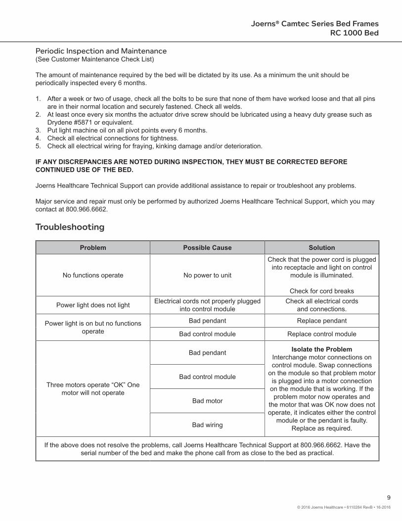
Troubleshooting
Problem Possible Cause Solution
No functions operate No power to unit
Check that the power cord is plugged into receptacle and light on control
module is illuminated.
Check for cord breaks
Power light does not light Electrical cords not properly plugged into control module
Check all electrical cords and connections.
Power light is on but no functions operate
Bad pendant Replace pendant
Bad control module Replace control module
Three motors operate “OK” One motor will not operate
Bad pendant Isolate the ProblemInterchange motor connections on control module. Swap connections
on the module so that problem motor is plugged into a motor connection on the module that is working. If the problem motor now operates and
the motor that was OK now does not operate, it indicates either the control
module or the pendant is faulty. Replace as required.
Bad control module
Bad motor
Bad wiring
If the above does not resolve the problems, call Joerns Healthcare Technical Support at 800.966.6662. Have the serial number of the bed and make the phone call from as close to the bed as practical.

10
Joerns® Camtec Series Bed FramesRC 1000 Bed
© 2016 Joerns Healthcare • 6110284 RevB • 16-2016
Customer Maintenance Check List
S/N Bed____________________________________ S/N Controller__________________________________
Bed Model__________________________________ Date_____________________Initial Date
1 Verify what options are on the bed:Foot End Side Rails ScaleHead End Side Rails TrapezePads (If Applicable) I.V. PoleOther______________________________________________________________
2 Verify and record the S/N3 Check Head Section operation with pendant4 Check Knee Gatch operation with pendant5 Check the Bed Elevation operation with pendant6 Check the Trendelenburg operation with pendant (If Applicable)7 Check the Seat operation with the pendant (If Applicable)8 Check casters function: Steer________ Total________9 Inspect the hardware to ensure that components are fit securely10 Check to ensure that the Electrical components are secure11 Check Power Cord for the following:
A: Check all strain reliefs and cable clamps are secureB: Check for worn areas, cuts or fraysC: Check plug for bent or loose prongs
12 Check that Pendant cord has no damage and that it is secured properly to the control box13 Check to ensure that all decals are affixed at proper location
Head, Foot and Motor decalsPower and Control Cord on Head BoardPower and Control on the Control Box
14 Check the presence and fit of the Mattress Stop15 Check the presence, fit and operation of the Emergency Crank16 Check the operations of all accessory options noted in #1 above17 Check to ensure that the side rails function properly and lock in place18 Measure and record the Leakage Current value should be less than 250 microamperes
(UL 60601-1) Use Calibrated Model LT544D-20 Digital Safety Analyzer or equivalentMeasured Value____________
19 Measure and record Line Grounding Resistance. Value should read equal to or less than 0.1 OHMS as measured between the ground wire in the line cord and the bed frame.
Measured Value____________20 Visually inspect the bed for paint or assembly defects; touch up as needed21 Check the Top Expansion (If Applicable) of the Mattress during operation at:
Head Section Right ________ Left ________Center Section Right ________ Left ________Upper Knee Gatch Right ________ Left ________Lower Knee Gatch Right ________ Left ________

11
Joerns® Camtec Series Bed FramesRC 1000 Bed
© 2016 Joerns Healthcare • 6110284 RevB • 16-2016
Customer Maintenance Check List Continued...
Initial Date22 Lubricate all pivot points with a light machine oil. (This should be done approx. every 6 months)23 Lubricate the actuator drive screws using a heavy duty grease such as Drydene #5871 or
equivalent. (This should be done approx. every 6 months)24 If bed is a Scale Bed, check that the scale functions are operating properly (if applicable)25 Check that all scale/exit alarm connections are secure (if applicable)26 Test bed exit alarm (if applicable)
Comments
Inspector Signature_______________________________________________ Date_________________________
12
Joerns® Camtec Series Bed FramesRC 1000 Bed
© 2016 Joerns Healthcare • 6110284 RevB • 16-2016
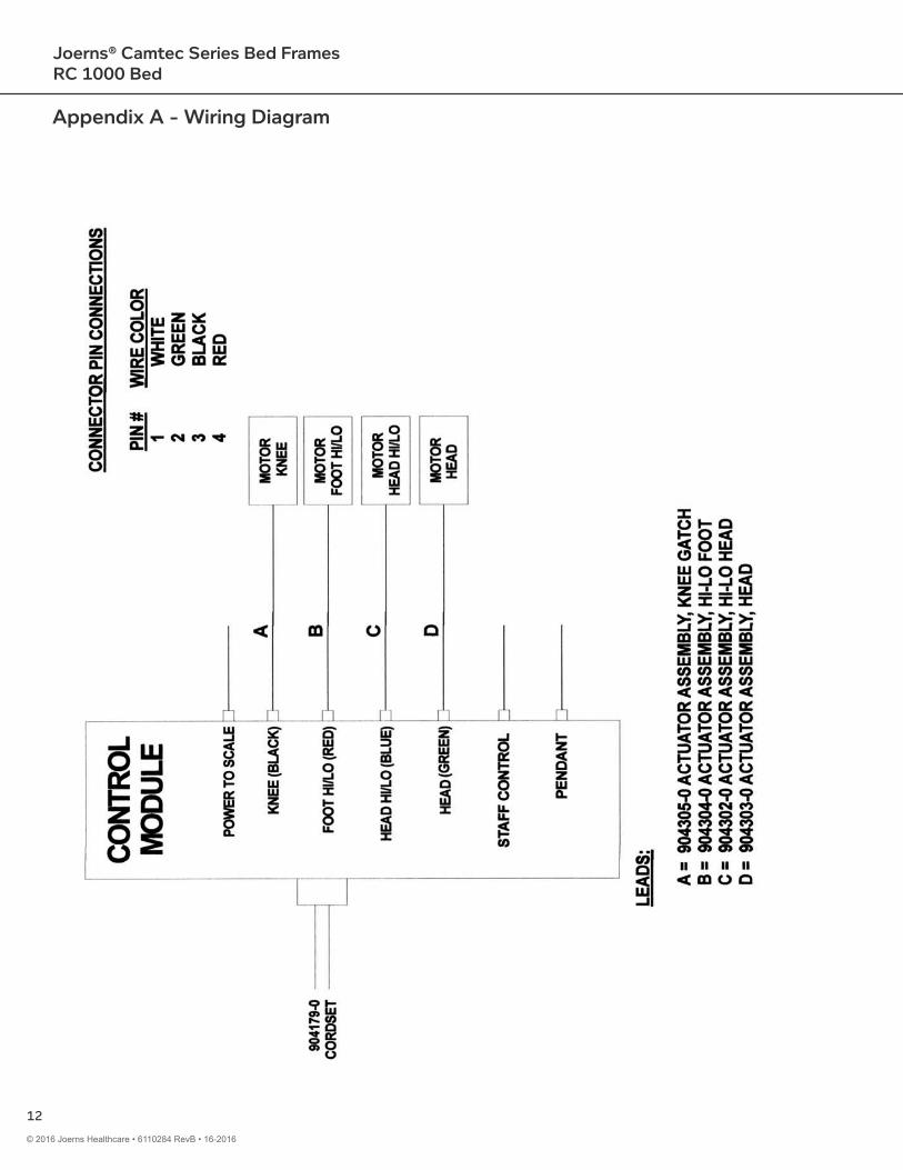
Appendix A - Wiring Diagram
13
Joerns® Camtec Series Bed FramesRC 1000 Bed
© 2016 Joerns Healthcare • 6110284 RevB • 16-2016
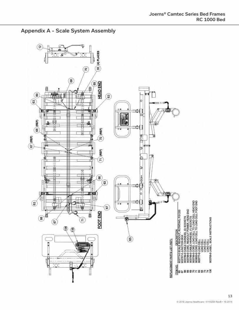
Appendix A - Scale System Assembly
14
Joerns® Camtec Series Bed FramesRC 1000 Bed
© 2016 Joerns Healthcare • 6110284 RevB • 16-2016
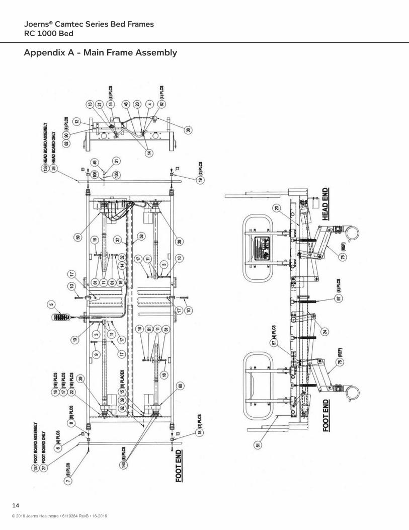
Appendix A - Main Frame Assembly
15
Joerns® Camtec Series Bed FramesRC 1000 Bed
© 2016 Joerns Healthcare • 6110284 RevB • 16-2016
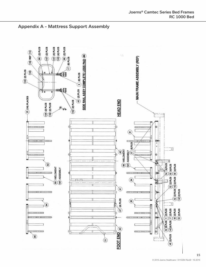
Appendix A - Mattress Support Assembly
16
Joerns® Camtec Series Bed FramesRC 1000 Bed
© 2016 Joerns Healthcare • 6110284 RevB • 16-2016
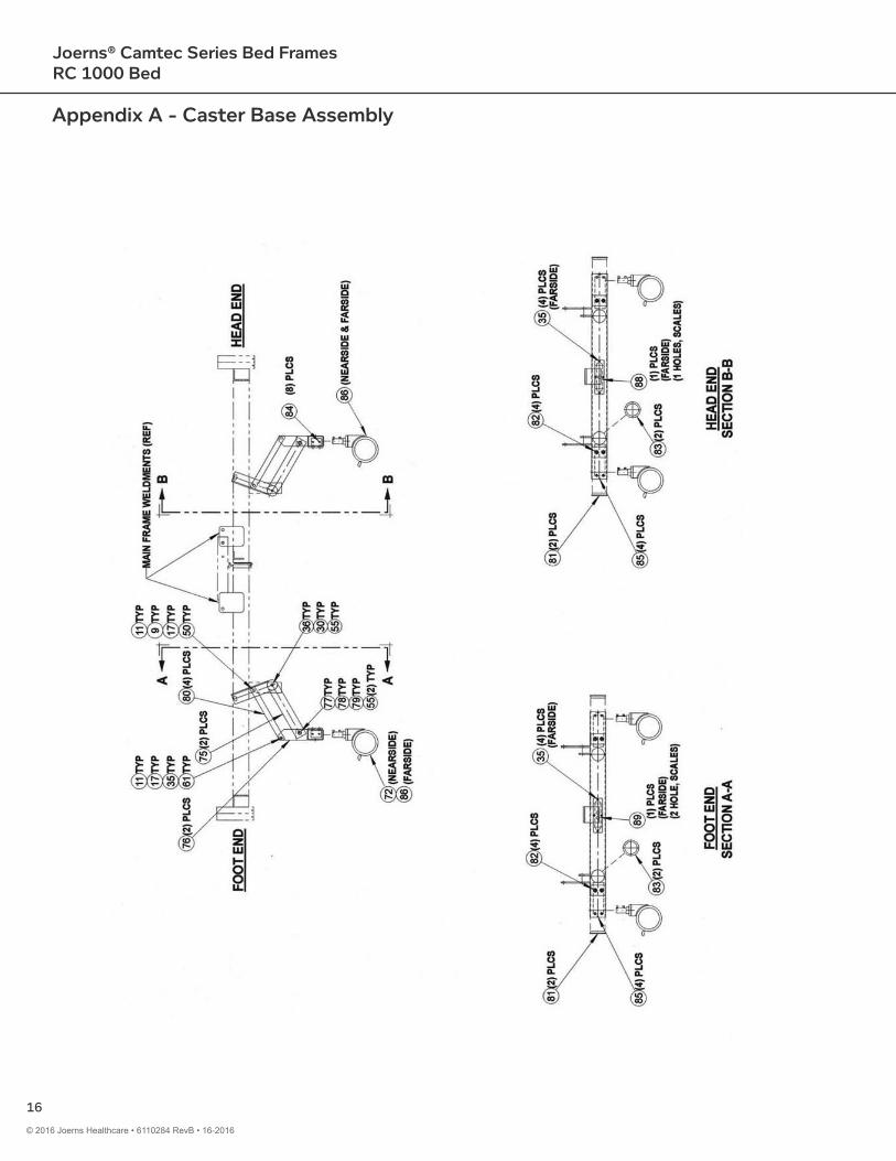
Appendix A - Caster Base Assembly
17
Joerns® Camtec Series Bed FramesRC 1000 Bed
© 2016 Joerns Healthcare • 6110284 RevB • 16-2016
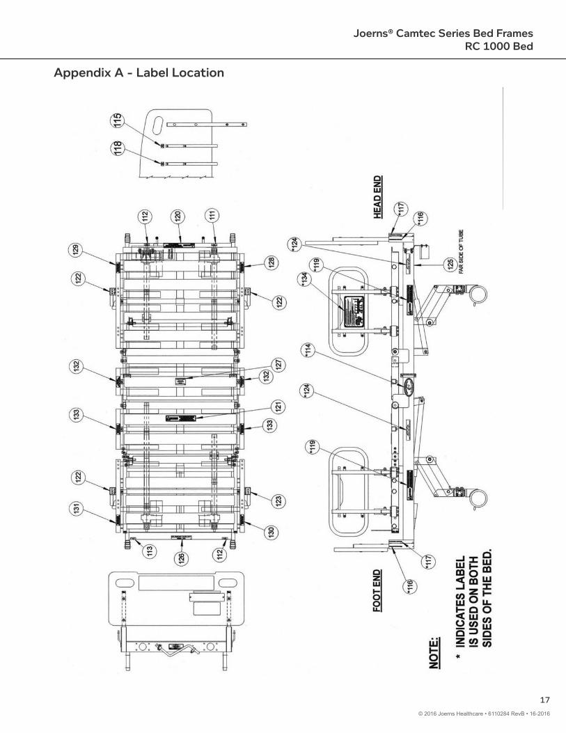
Appendix A - Label Location
18
Joerns® Camtec Series Bed FramesRC 1000 Bed
© 2016 Joerns Healthcare • 6110284 RevB • 16-2016
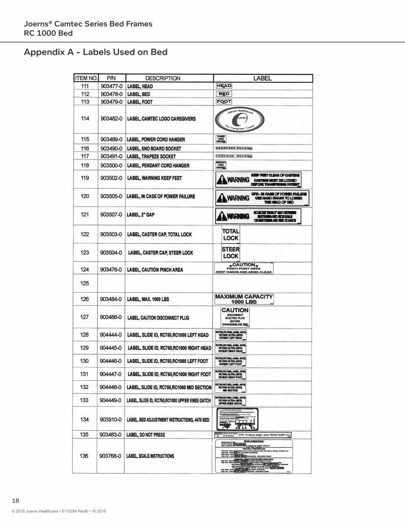
Appendix A - Labels Used on Bed

19
Joerns® Camtec Series Bed FramesRC 1000 Bed
© 2016 Joerns Healthcare • 6110284 RevB • 16-2016
Appendix A - Parts List
Item Part No. Description1 106668-1GY Cover Plate23 106141-0 Spacer, ½ x 1½4 903172-0 Spring Clip5 903950-0 Pendant, 10 Button6 900653-0 Cap Plug7 903637-0 Head Board Bold, ¼-20 x 30mm8 903165-0 Head Board Nut, ¼-20 x 17mm9 902512-0 Bolt, Hex, ⅜-16 x 2" LG
10 903118-0 Bolt, Hex, ⅜-16 x 2½" LG.11 900419-0 Washer, Nylon, ½ x ¾ x 1/1612 904009-0 Controller, W/Molex Connectors, 5 Function13 903174-0 Grommet, ¾ x 1⅛, Rubber14 901061-0 Screw, #10-32 x ½, Round Head Phillips, S/S15 900094-0 Nut, Hex, #10-32, Elastic Lock16 902513-0 Bolt, Hex, ⅜-16 x 1" LG17 902518-0 Nut, Hex, ⅜-16, Elastic Lock18 300591-0 Assembly, Foot Board Support19 300592-0 Assembly, Head Board Support20 106167-0 Emergency Crank Clamp Bracket21 106166-0 Emergency Crank Bracket22 903924-0 Casting, Actuator Mounting23 24006630GY Main Frame, Head End (Old Part Number: 203386-0)24 24006631GY Main Frame, Foot End (Old Part Number: 203381-0)25 903458-0 Caplug, 1¼" SQ26 904312-0 Head Board27 904309-0 Foot Board28 903811-0 Fowler Actuator29 903802-0 Knee Gatch Actuator30 903154-0 Bolt, Hex, ½-13 x 2" LG31 903175-0 Washer, Finish, #832333435 900328-0 Screw #10-32 x ¼ Pan Head Phillips SS36 903152-0 Bushing, ⅝ x 1⅛37 903810-0 Cable, Knee Gatch Motor, Split to Controller38 904179-0 Cordset39 903180-0 Cable Clamp, 5/16 Nylon40 203060-0GY Weldment, Lower Knee Gatch41 203057-0GY Weldment, Upper Knee Gatch

20
Joerns® Camtec Series Bed FramesRC 1000 Bed
© 2016 Joerns Healthcare • 6110284 RevB • 16-2016
Appendix A - Parts List
Item Part No. Description42 203050-0GY Weldment, Fowler43 903923-0 Casting, Side Rail, Pivot44 300309-0 Assembly, Side Rail, Wing Type45 903176-0 Screw #8 x ½" LG Oval Head Phillips, SS46 203204-1RD Weldment, Emergency Crank, Red47 903925-0 Casting, Hinge Half48 104574-0GY Knee Gatch Connector Link49 106071-0 Spacer, 0.937" LG50 106111-0 Spacer, 1 5/16" LG51 107170-0-GY Mattress Stop Flat, Flip-Up52 900129-0 ⅜" Lock Washer, HELICAL53 902514-0 Bolt, Hex, ⅜-16 x 1½54 106072-0 Spacer, 0.625 OD x 0.343 LG55 903173-0 Washer, Nylon, ⅝ x 1⅛ x 1/1656 903115-0 Bolt, Hex, ½-13 x 1¼57 900658-0 Cap Plug, 1 x 258 903809-0 Cable, Hi Lo Foot End Motor, Split to Control Box59 903812-0 Hi Lo Head End Actuator60 903803-0 Hi Lo Foot End Actuator61 104592-0 Spacer, ½" x 9/16"62 901007-0 Screw, 10-32 x ⅝ Round Head Phillips SS63 903777-0 Load Cell6465 903773-0 Scale Readout, Rotating66 903789-0 Cable Harness, Spread Base, (2) Sockets67 903787-0 Junction Box, Spread Base68 903798-0 Cord, Readout Power, Head End69 903788-0 Cable Harness, Spread Base (1) Socket70 903799-0 Cord, Load Cell to Load Cell Head End71 903800-0 Cord, Load Cell to Load Cell Foot End72 903938-0 Caster, Steer Lock737475 24006637GY Weldment, Leg Link (Old Part Number: 203390-0)76 24006642GY Weldment, Axle, 4475 Bed (Old Part Number: 203379-0)77 900411-0 Nut, Hex, ½-13 Elastic Lock78 904369-0 Bushing, ½" x ⅝" x ⅞" LG79 903155-0 Bolt, Hex, ½-13 x 2½"80 104575-0GY Leg Connector Link81 901237-0 Cap 2" x 3"82 901233-0 Shoulder Bolt, Load Cell ½" DIA 1.250" Long

21
Joerns® Camtec Series Bed FramesRC 1000 Bed
© 2016 Joerns Healthcare • 6110284 RevB • 16-2016
Appendix A - Parts List
Item Part No. Description83 903234-0 Plug, 2½" DIA Hole84 903235-0 Socket Set Screw, 5/16-18 x ⅜85 903194-0 Screw #6 x ⅜ SS Phillips86 903937-0 Caster, Total Lock8788 106668-2GY Mounting Plate, Scales, 2 Holes89 106668-0GY Mounting Plate, Scales, 1 Hole90 900171-0 Washer, Lock, #10 Internal Tooth91 203350-0GY Weldment, Side Rail Support, LH Fowler92 203351-0GY Weldment, Side Rail, Support, RH Fowler93 203352-0GY Weldment, Mattress Support, Mid Section94 203353-0GY Weldment, Mattress Support, Upper Knee Gatch95 203354-0GY Weldment, Side Rail Support, LH Lower Knee Gatch96 203355-0GY Weldment, Side Rail Support, RH Lower Knee Gatch97 300587-0 Assembly, Adjustable Side Rail Release Plunger98 904342-0 Spring, Compression99 904343-0 Caplug, COF ½
100 900016-0 Nut, Hex, ¼-20 Elastic Lock101 900258-S Washer, Lock, ¼" Split, SS102 900991-0 Washer, Nylon, ⅜ x ¾ x 1/16103 901071-0 Screw, ¼-20 x ⅝" LG Pan Head Phillips SS104 902014-0 Spring Pin, ¼" DIA x 1½" LG105 106459-0 Strap, Cord Hanger, Velcro Loop106 106460-0 Strap, Cord Hanger, Velcro Hook107 203650-0GY Weldment, Side Rail Lock Pin108 104636-1GY Side Rail Release Rod109 404003-4 Assembly, Side Rail Cushion, D-P Navy109 904450-0 Board, Side Rail Cushion Replacement (Composite)110 203006-1GY Weldment, Side Rail Foot End111 903477-0 Label, Head112 903478-0 Label, Bed113 903479-0 Label, Foot114 903482-0 Label, Camtec Logo Caregivers115 903489-0 Label, Power Cord Hanger116 903490-0 Label, End Board Socket117 903491-0 Label, Trapeze Socket118 903500-0 Label, Pendant Cord Hanger119 903502-0 Label, Warning Keep Feet120 903505-0 Label, In Case of Power Failure121 903507-0 Label, 2" Gap122 903503-0 Label, Caster Cap, Total Lock

22
Joerns® Camtec Series Bed FramesRC 1000 Bed
© 2016 Joerns Healthcare • 6110284 RevB • 16-2016
Item Part No. Description123 903504-0 Label, Caster Cap, Steer Lock124 903476-0 Label, Caution Pinch Area125126 903484-0 Label, Max. 1000 lbs127 903488-0 Label, Caution Disconnect Plug128 904444-0 Label, Slide ID, RC750, RC1000 Left Head129 904445-0 Label, Slide ID, RC750, RC1000 Right Hand130 904446-0 Label, Slide ID, RC750, RC1000 Left Foot131 904447-0 Label, Slide ID, RC750, RC1000 Right Foot132 904448-0 Label, Slide ID, RC750, RC1000 Mid Section133 904449-0 Label, Slide ID, RC750, RC1000 Upper Knee Gatch134 903909-0 Label, Bed Adjustment Instructions, 4475 Bed135 903483-0 Label, Do Not Press136 903768-0 Label, Scale Instructions137 300328-0 Foot Board Assembly, Scales Plastic138 300242-0 Head Board Assembly, Plastic139 12470022 TIP, ¼" Rod, Caplug (Old Part Number: 900100-0)140 903605-0 Washer, Rubber, ½" Screw Size141 300660-0 Assembly, Mattress Support, Mid Section142 904072-0 Bolt, Hex ⅜-16 x ⅝" LG.
Appendix A - Parts List
23
Joerns® Camtec Series Bed FramesRC 1000 Bed
© 2016 Joerns Healthcare • 6110284 RevB • 16-2016
Accessories FG1250 Base Scale
FG1250 Basic Operational Flow
Initializing System Zero
Note: When power is first applied to the system, the display will read “AC POWER LOST! - REFER TO MANUAL”. This indicates that there was an interruption in power and to check the patient weight. To reset the system, press the “FREEZE/RESUME” button.
Before patient is placed on to the bed, you must first set the system zero. This is done as follows:
Sets the initial system zero reference.
1. Press and hold the “0.0” button. The displayed message will indicate “HOLD TO ZERO” as the digit to the right counts down.
2. When the message changes to “PLEASE WAIT - HANDS OFF”, release the button and do not touch the bed. In a few seconds the display will indicate “WEIGHT = 000.0 LB” The patient may now be placed on the bed.
Important: When the “0.0” button is pressed, everything on the weighing surface will be zeroed out on the display. Make sure that all linens, pillows, etc., are in place before pressing the “0.0” button so that they will not appear as part of the patient’s weight.
After the patient has been placed on the bed, simply press and release the “ON” button. The displayed message will read: “PLEASE WAIT - HANDS OFF”. Do not touch the bed. After a few seconds the patient’s weight will be displayed.
Any variation in weight will now be viewed as a “+” or “–” figure relative to zero. Pressing the “WEIGHT” button will switch back to the WEIGHT MODE allowing you to view the patient’s total weight again.
Note: When you rest the system zero, the WEIGHT CHANGE MODE will also be reset to zero.
Button Functions
The WEIGHT CHANGE mode is used to monitor the patient’s weight relative to zero.
1. Press the “WT CHG” button. The display will read” “WT CHG = (patient weight)”. 2. Press the “0.0” button to set the relative zero.
24
Joerns® Camtec Series Bed FramesRC 1000 Bed
© 2016 Joerns Healthcare • 6110284 RevB • 16-2016
Loss of Power
If it becomes necessary to disconnect the bed power while the scale is in use:
1. Note the displayed patient weight before disconnecting the power.2. Unplug the bed and move bed and patient to the new location.3. When the patient is settled restore the power to the bed.4. Press the “FREEZE/RESUME” button to WAKE-UP the readout. If the weight reading is correct, the system
is ready.5. If the displayed reading is not correct:
a. Press the “FREEZE/RESUME” button. The display will read “HOLD (weight)”b. Use the “WEIGHT” and “WT/CHG” keys to ramp the displayed value to the correct weight.c. When done, press the “FREEZE/RESUME” button once again to save the correction and exit to the normal
weighing mode. If you make a mistake, press “ON” to about your changes.
Important: If you do not know the correct patient weight, you must remove the patient from the bed and re-zero the system.
1. Press the “FREEZE/RESUME” button. The display will read: “FREEZE = (patient weight)”.2. Make all necessary adjustments to bed and/or patient.3. Press the “FREEZE/RESUME” button once again to resume normal weight monitoring.
Moving Bed and Patient
If it becomes necessary to move the bed and/or patient while the scale system is active, use the following procedure:
Toggles between POUNDS and KILOGRAMS display modes.
While in the FREEZE mode, the “WEIGHT” and “WT/CHG” keys will allow you to manually adjust the displayed weight reading in the event of a know error. Simply press the “WEIGHT” and “WT/CHG” keys to make the proper corrections.
Note: If FREEZE mode is left unattended for more than three minutes, display will read “LEFT IN FREEZE - REFER TO MANUAL”. You must press the “FREEZE/RESUME” button to exit this mode.
This feature will allow you to make adjustments to the bed without effecting the displayed patient weight.
1. Press the “FREEZE/RESUME” button. The display will read: “FREEZE = (patient weight)”.2. Make all necessary adjustments to the bed.
25
Joerns® Camtec Series Bed FramesRC 1000 Bed
© 2016 Joerns Healthcare • 6110284 RevB • 16-2016
System Calibration and Maintenance
Important: The following calibration procedure should only be performed by qualified service personnel. The 1228 load cell, itself, has no user serviceable components and should not be tampered with for any reason.
Recalibration is generally not required, but should be checked periodically to ensure accuracy.
Calibration Procedure
Calibration Tolerance Table
Low Limit Applied Load High Limit99.9 100.0 100.1
199.8 200.0 200.2299.7 300.0 300.0399.6 400.0 400.4499.5 500.0 500.5599.4 600.0 600.6699.3 700.0 700.7799.2 800.0 800.8899.1 900.0 900.9999.0 1000.0 1001.0
Cleaning and Disinfecting
The readout and transducer for the 1228 Scale System are made of aluminum and steel with a painted surface. You need only exercise caution when cleaning the display window as this is made of clear polyester. We recommend mild soap and water for general cleaning.
1. Press the “FREEZE/RESUME” button to enter the FREEZE MODE.
6. Press the “FREEZE/RESUME” to save changes or “ON” to abort changes.
2. When the display indicated “FREEZE = (weight)”, press and hold the “LB/KG” button. The display will read “CAL” as the right hand digit counts down to enter the CAL MODE.
3. When in the CAL MODE, press the “0.0” button to zero the display.
4. Place a known weight on to the weighing surface and compare it to the displayed reading.
5. Use the “WEIGHT” and “WT/CHG” keys to make any necessary adjustments to the displayed value. The displayed value should be within 0.1% of the calibrated weight plus or minus 1 digit of reading.

Post Acute, Acute, HomeCare 2430 Whitehall Park Dr. Ste 100Charlotte, NC 28273(P) 800.826.0270(F) 800.457.8827
VA/Government19748 Dearborn StreetChatsworth, CA 91311(P) 800.966.6662(F) 800.232.9796
United Kingdom and Other Countries+44 (0)844 811 1156+44 (0)844 811 1157
Netherlands+31 (0)30 6363700+31 (0)30 6363799
VA/Government19748 Dearborn StreetChatsworth, CA 91311(P) 800.966.6662(F) 800.232.9796
www.joerns.com • email: [email protected] © 2016 Joerns Healthcare • 6110284 RevB • 16-2016
Canadian Office4056 Meadowbrook Dive, Unite #148London, ON Canada N6L 1E5(P) 866.546.1151(F) 519.451.8662
Joerns RC 1000 Beds, Model RC1000, are guaranteed for a period of one years from the date of delivery, against defects in materials and workmanship, under normal use and service.
This one-year warranty includes all mechanical and electrical components.
Steel structural components on beds are covered under warranty for a period of five years from the date of delivery.
Welds are covered under warranty for the lifetime1 of the product.
Damage caused by use in unsuitable environmental conditions, abuse or failure to maintain the product in accordance with user and service instructions is not covered.
Any alteration, modification, or repair unless performed by or authorized in writing by Joerns Healthcare, will void this warranty.
Parts
Joerns beds contain various parts that wear from normal use. These parts are not covered under the stated warranty but are covered for 90 days after date of delivery.
Joerns Healthcare’s obligation under this warranty is limited to supplying replacement parts, servicing or replacing, at its option, any product which is found by Joerns Healthcare to be defective.
Warranty replacement parts are covered by the terms of this warranty until the product’s original stated warranty period expires.
When requested by Joerns Healthcare, parts must be returned for inspection at the customer’s expense. Credit will be issued only after inspection.
Service
Most service requests can be handled by the facility Maintenance Department with assistance from the Joerns Healthcare Product Service Department.
Most parts requested can be shipped next day air at the customer’s expense.
Should a technician be required, one will be provided by Joerns Healthcare, at our discretion. Only the Joerns Healthcare Product Service Department can dispatch authorized technicians.
This warranty is extended to the original purchaser of the equipment.
1 Weld lifetime defined as 15 years.
Joerns Healthcare Warranty Programfor Joerns® RC 1000 Bed, Model RC1000
Manufactured by:Joerns Healthcare2100 Design Rd.Arlington, TX 76014