Embed Size (px)
Citation preview

GMW
__________________________________________________________________________________
GMW
955 Industrial Road, San Carlos, CA 94070 Tel: (650) 802-8292 Fax: (650) 802-8298 Email: [email protected] Web site: http://www.gmw.com
USER’S MANUAL
MODEL: MC- XYZT, MOTION CONTROL
For GMW Model 5201 Projected Field Electromagnet
PROPRIETARY
THIS DOCUMENT CONTAINS CONFIDENTIAL INFORMATION PROPRIETARY TO GMW ASSOCIATES. IT MUST NOT BE REPRODUCED OR DISCLOSED TO OTHERS OR USED IN ANY WAY EXCECPT FOR THE INSTALLATION, OPERATION OR MAINTENANCE OF GMW ASSOCIATES PRODUCTS.
File No: GMW_MOTION_CONTROL_VXM_V2_August19-05.doc Revision Date: August 19, 2005

TABLE OF CONTENTS
SPECIFICATIONS Section 1 SYSTEM DESCRIPTION Section 2 SYSTEM REQUIREMENTS Section 3 INSTALLATION Section 4 SOFTWARE Section 5 Starting and Stopping the Software 5.1 GPIB Address Selection 5.2 Setup 5.3 Table Mode 5.4 Set X, Y, Z Home 5.5 Set CCW, CW Home 5.6 Reset X, Y, Z and Angle counter 5.7 X, Y, Z and Angle position 5.8 Start Rotation, Start X, Y, Z 5.9 Stop Rotation, Stop X, Y, Z Motion 5.10 Software Limit for Angle, X, Y and Z 5.11 Limit LED 5.12 APPENDIX Section 6 DRAWINGS 6.1 NATIONAL INSTRUMENTS GPIB/RS232 CONVERTER DATA SHEETS 6.2 VELMEX VXM-2 MOTOR CONTROLLER SPECIFICATION 6.3 GMW MOTION CONTROL PARTS LISTS 6.4

Section 1 SPECIFICATIONS
General: Controller Package: EIA 19” rack mounting cabinet, 3U high Controller Dimensions: 447.00 mm (wide) x 146.00 mm (high) x 425.00 mm
(deep) (17 5/8” x 5 3/4” x 16 3/4”) Controller Weight: 14.2 kg (31.5 lb.) Power Supply: CONDOR, HCC15-3-A+ Power Requirements: 115ACV/60Hz, 1.5A 220ACV/50Hz, 1.0A Motor Controller: VELMEX Stepping Motor Controller Model VXM-2 One controller has provision for controlling two motors One or two controllers fitted. Computer interface: GPIB Motion Stages: X: Slave Velmex Controller Motor 1. Max range of 200 mm. Y: Slave Velmex Controller Motor 2. Max range of 200 mm. Z: Optional stage. Master Velmex Controller Motor 2. Max range of 30 mm. T: Master Velmex Controller Motor 1. Angle about Z axis. Max range of 360 Deg. Motion Stage Weight (without magnet): 9.5 kg (21.0 lb.) with X, Y, T stages 13.0 kg (29.0 lb.) with X, Y, Z, T stages
CAUTION: The rotary stage does not have limit switches build in. User should be cautious about the angle position. More than a 360 degree rotation will cause damage to the cable and water hose to the magnet. It is recommend that after powering up the controller, user manually adjust the rotary stage to zero degree while watching the cables and water hose. Manual reset Angle counter afterwards Motion stage T is always provided. X, Y, Z motion stages are optional.

Section 2 SYSTEM DESCRIPTION
The system consists of the following main components.
-2 VELMEX Stepping Motor Controllers. Model: VXM-2. Each VXM-2 can control up to two motors. Provision of controlling total four motors. One Motor Controller is configured as Master controller, the other Motor Controller is configured as Slave Controller. The two motors connected to master controller are recognized as motor 1 and 2 by the system, the two motors connected to slave controller are recognized as motor 3 and 4.
-Power supply. CONDOR model HAA15-0.8-A+, dual adjustable outputs. Provide electrical power both for the motor controllers and GPIB/RS232 converter.
-National Instruments GPIB/RS232 converter. Convert RS232 interface at VXM-2 to GPIB interface.
-Linear stages provide X, Y and Z motion.
-Rotary stage provides angle motion.
-Software provided on CD. National Instruments NI-GPIB driver CD. GMW Motion Control Software CD -Executable file. -Installer files. -PDF manual (This document). -LabVIEW Source Code.

Section 3 SYSTEM REQUIREMENTS
-AC line voltage: 115-220ACV/50-60Hz
-Computer: Windows2000/NT/XP, GPIB interface card installed, CD-ROM for installing software.
-LabVIEW 7.0 or later for running, viewing and modifying software. Not require if the executable version of Motion Control software provided is used.
-LabVIEW Run Time Engine 7.0 for running executable version of the software. Executable version Motion Control software does not require LabVIEW but requires LabVIEW Run Time Engine 7.0. It is included in the Motion Control software CD.
Section 4 INSTALLATION
4.1 –Verify the GPIB and required drivers are installed in the computer.
4.2 – Verify the AC voltage selector on the rear panel of the Motion Control set to the correct line voltage.
4.3 – Connect GPIB cable from computer to the Motion Control Interface.
4.4 – Connect power cord to the Motion Control Interface.
4.5 – Connect cables to all the motors.
Each stage has two cables. One is for the motor; one is for the limit switches. Both cables need to be connected. Connect Rotary stage to Master Motor 1, X stage to Slave Motor 1, Y stage to Slave Motor 2. Connect optional Z stage to Master Motor 2.
4.6 – Power on computer.
4.7 – Power on Motion Control Interface.
The Found New Hardware wizard will find the NI-GPIB/RS232 converter automatically. Follow the instruction to install the necessary driver into computer. Please refer to the document provided on the GPIB driver CD for more information.
4.8 – Install LabVIEW7 software.
Skip this step if LabVIEW7 was already installed or it is intended to use executable version of Motion Control software.

Section 4
INSTALLATION
4.9 – Verify the hardware is installed correctly.
Double click the icon of Measurement & Automation on the desk top to open MAX. Go to My System>>Devices and Interfaces>>GPIB0. Right click on the right side window. Select Scan for Instruments. If an entry shows an instrument at address 1, the device is installed correctly. GPIB address was preset to 1 at factory. User can change the GPIB address if needed. Refer to the documentation on the GPIB driver CD from National Instruments for more information about how to change GPIB address.
4.10 – Install Motion Control software.
The Motion Control software CD includes both source VI and executable version. Source VI is the source code for LabVIEW. LabVIEW 7.0 or later is required for viewing, modifying and running VI. Executable version is a stand alone version. It does not require LabVIEW to run but requires LabVIEW Run Time Engine7.0. LabVIEW Run Time Engine 7.0 is included in the Motion Control software CD.
Close the MAX and any other programs that may be open. Insert Motion Control software CD. The installation should start automatically. If the installation does not start automatically, run Setup.exe from the CD. Setup.exe is in the folder Installer on the CD. After installing Motion Control software, it will prompt user if LabVIEW RunTime Engine 7.0 will be installed.
4.11 – Restart computer.

Section 5 SOFTWARE DESCRIPTION
5.1 – Starting and Stopping the Software
To open the program, go from Start>>Programs>>GMW Motion Control>>Motion Control V2
Click on the white arrow button on the top of the screen to start the software.
Click Stop button or use <Esc> key to stop the software.
Figure 1.Main control window
5.2 – GPIB Address Selection
Select GPIB address. Default GPIB address is 1.

Section 5 SOFTWARE DESCRIPTION
5.3 – Setup Set up the parameters for the software. When click the button of SETUP, a Setup window will appear.
Figure 2. Setup Window 5.3.1 – Save Configuration. Will save the current configuration. The software will use the saved configuration next time it starts if the configuration was saved. If the configuration was not saved, the software will still use the current configuration but will use the previously saved configuration next time the software starts.
5.3.2 – Load Default Configuration. Will load the default settings.
5.3.3 – Exit Setup. End the setup process and close the setup window. 5.3.4 – Axis-Motor#. Assign the individual stage to the motor control port on the motor controller. X, Y and Z are for linear stages, T is for rotary stage. By default, X is motor 3 (Slave motor1), Y is motor 4 (Slave motor 2), T is motor 1 (Master motor 1), Z is motor 2 (Master motor 2).

Section 5 SOFTWARE DESCRIPTION
5.3.5 – Offset. Used for setting the home position. X, Y and Z Offset are the linear offset positions from the low limit switch where the step motor counter will be set to zero. CW and CCW Offset are the offsets from the home switch to zero degree position. CW is the clockwise offset; CCW is the counter-clockwise offset. 5.3.6 – Resolution. Linear resolution is 400 steps per 1 mm. Rotary resolution is 40 steps per 1 degree. Resolution settings are determined by the motor and motion stages. User should not change the resolution settings unless the motion stages are changed. 5.3.7 – Speed. Define the speed. The default linear speed is 1mm/second for X and Y, 0.5mm/second for Z. The default rotary speed is 10 degree/second.
5.4 – Table Mode. The Table mode LED OFF indicates the software run at manual mode. The Table mode LED ON indicates the software run at table mode. Click Table Mode LED, a Table Mode Setup window will appear.
Figure 2. Table Mode setup window

Section 5 SOFTWARE DESCRIPTION
When running at Table mode, user can either manually enter a table or load a table from a file. The first column is for Step index. The second column of the table is the axis intended for moving. X, Y and Z are for linear stages accordingly. T is for rotary stage. The third column is the position intended to move to. The unit for linear stage is mm. The unit for rotary stage is degree. The table is ended by the word “END”. The word “END” is used to indicate the end of the table. User can construct a table using EXCEL or any word processing software. The table file must have the same structure as the table shown but without the column for Step index. It consists two columns, one for axis, and one for position. The table ended by the word “END”. The column uses Tab as delimiter.
5.4.1 – Load Table From file. Will prompt user for loading a pre-saved table file. 5.4.2 – Save Table to File. Will prompt user for file name and location to save current table on the screen to a file for later use. 5.4.3 – Start Table Mode. Close the Table Setup window and start running the software at Table mode using the table on the screen. 5.4.4 – Abort Table Mode. Close the Table Setup window and return to the software to manual mode. 5.4.5 – Error LED. Indicates if the table includes value out of the software limit set by user. When out of limit error occurs, the software will not go to table mode unless the error is corrected or the Table mode is aborted.
5.4.6 – Time Between steps (Sec). Specify how many seconds will pause between steps. 5.4.7 – Total Number of Runs. Specify how many times user wants repeat the table.
5.5 – Set X, Y, Z Home
Home position is the position the counter of stepping motor controller is zero. Each time the stepping motor power off/on, the counter is set to zero, regardless the physical position of the stages. Before use, user need to establish the home position either using the Set Home buttons or Reset Counter buttons.
Click one of the buttons Set X Home, Set Y Home, Set Z home. The linear stage will move to the lower end of the station. When the limit switch is hit, the motion will stop, the stage will move back the distance defined as X, Y, Z Offset at the Setup window. The counter of motor controller, X, Y or Z, will set to zero accordingly.
5.6 – Set CCW, CW Home
Click one of the buttons CCW Home, CW Home. The rotary stage will move either counter-clockwise (CCW) or clockwise (CW) towards 0 degree. It will rotate back 25 degrees (1000 steps) and goes to the 0 degree again. CCW and CW offset is the distance between the point Home switch is activated and 0 degree. CCW and CW offset is defined within Setup window.
CAUTION: The rotary stage does not have limit switches build in. User should be cautious about which direction to set Home. More than a 360 degree rotation will cause damage to the cable and water hose to the magnet. It is recommend that after powering up the controller, user manually adjust the rotary stage to zero degree while watching the cables and water hose. Manual reset Angle counter afterwards.

Section 5 SOFTWARE DESCRIPTION
5.7 – Reset X, Y, Z and Angle counter
Used for manually reset the counter of the controller. The current position will be 0 mm for linear stages, 0 degree for rotary stage after Reset Counter button being clicked.
5.8 – X, Y, Z and Angle position
Read back the current position of the stages. X and Y positions are displayed after the moving is stopped. Angle position and Z position can be displayed during the moving.
5.9 – Start Rotation, Start X, Y, Z
Manually start the motion to the position defined by user. The position is entered either typing in the position box or using the slide. The position can be positive or negative.
5.10 – Stop Rotation, Stop X, Y, Z Motion
Stop the motion during the scan.
5.11 – Software Limit for Angle, X, Y and Z
Set up by either typing in the two boxes or using the slides. The software limits define the minimum and maximum target position. The software limits also define the minimum and maximum target position can be used in table mode. At manual mode, target position over the software limits is ignored and the limit value is used instead. At table mode, target position over software limit will cause an error; user needs to change the target position or abort the table mode to proceed. Default volumes of software limit can be changed within Setup Windows.
5.12 – Limit LED
If the linear stages reached one of the limit switch mounted at the linear stages on both ends, the motion will stop, the Limit LED will lit, indicating the physical limit is reached.
CAUTION: Limit switch only installed on linear stages. There is no limit switch on the rotary stage for over rotation protection. More than 360 degree rotation will cause damage to the cables and water hose to the magnet.

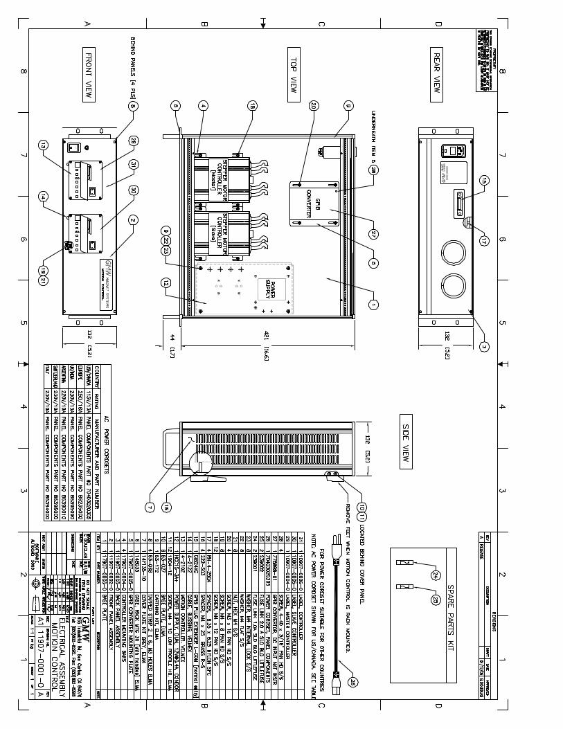
Section 6.1 APPENDIX - DRAWINGS
6.1 - Drawings 11907-0006-0_Rev_A – Mechanical Assembly for XYZT 11902520_Rev A – Mechanical Assembly for XYT 11902530_Rev A – Electrical Assembly 11907-0001-0_Rev_A – Controller Assembly

X STAGE
Y S
TA
GE
T (ANGLE) STAGE
Z STAGE
XY Axis Stages = Part No: 11907-0004-0XYT Axis Stages = Part No: 11907-0005-0XYZT Axis Stages = Part No: 11907-0006-0
GMW MAGNET SYSTEMS
MC-XYZT MOTION CONTROL
955 Industrial Rd, San Carlos, CA 94070, USA. Tel: (650) 802-8292 Fax: (650) 802-8298 email: [email protected] web: www.gmw.com Made in USA 10907-0015-0


Section 6.2 APPENDIX – NATIONAL INSTRUMENTS GPIB/RS232 CONVERTER DATA SHEETS
688 National Instruments • Tel: (800) 433-3488 • Fax: (512) 683-9300 • [email protected] • ni.com
GPI
B ↔
Ser
ial C
ontr
olle
rs a
nd C
onve
rter
GPI
B In
stru
men
t Con
trol
/Con
nect
ivity
GPIB RS-232/485 Controllers and RS-232 Converter
• Completely IEEE 488.2 compatible• 256 KB RAM buffer• 8 RS-232 or RS-485 data transfer
rates up to 38.4 kb/s; hardwarehandshaking, and the XON/XOFFprotocols prevent data loss
• Cable lengths extend GPIB• Up to 15.6 m (50 ft.) for
GPIB-232CT-A and GPIB-232CV-A• Up to 1.2 km (4,000 ft.) for
GPIB-485CT-A
NI GPIB-232CT-A, NI-GPIB-485CT-A• Compatible with RS-422 ports
(GPIB-485CT-A)• NI-488.2 for Windows 3.1/DOS• Applications
• Integrate an RS-232/485instrument into a GPIB system
• Control a GPIB-based test system from a remote computervia RS-232/485
NI GPIB-232CV-A• Switch-selectable interface
parameters include IEEE 488address, transfer rate, parity,stop bits, word length, andtermination mode
• Special SRQ-ON-EMPTY featurefor maximum GPIB performance
• Applications• Print from a laptop computer
to an IEEE 488 printer• Interface an RS-232 device
to an IEEE 488 bus system
GPIB ↔ Serial Controllers and Converter
NI GPIB-232CT-A, NI GPIB-485CT-AOverviewThe National Instruments GPIB-232CT-A and GPIB-485CT-A can
turn any computer or terminal with an RS-232 or RS-485 port into a
full-function IEEE 488.2 controller. With the flip of a switch, the
NI GPIB-232CT-A or NI GPIB-485CT-A can make any RS-232 or
RS-485 device appear as a GPIB device. The small size of these
controllers makes them ideal for use with laptop computers or other
computers that have no internal I/O slots available.
The NAT4882 IEEE 488.2 ASIC implements the full range of GPIB
controller functions, including those controller functions required
and recommended by IEEE 488.2. All GPIB sequences and operations
conform to IEEE 488.2. External DIP switches set the operating mode,
the GPIB primary address, and serial port parameters.
Depending on the version, the GPIB-232CT-A and GPIB-485CT-A
controllers can accept either AC or DC power input. You can connect
either the GPIB-232CT-A or the GPIB-485CT-A to up to 14 GPIB
instruments. In addition, when you pair the GPIB-485CT-A with an
RS-485 board for the PC, such as the National Instruments PCI-485,
you can use it as a cost-effective GPIB extender up to 1.2 km (4,000 ft).
Controller CapabilitiesData Buffer – A FIFO data buffer helps maximize performance.
The GPIB-232CT-A and GPIB-485CT-A can continue to accept data
from the serial or GPIB port while the other port is busy.
Complete Status Update – The GPIB-232CT-A and GPIB-485CT-A
handle both continuous and requested status and error reporting in
either symbolic or numeric form.
Symbolic status reporting is useful for direct viewing on a terminal
(CMPL for complete, ERR for error, and so on). Numeric status
reporting is useful for processing by an application.
Modes of OperationYou can use either controllers in either Serial (S) or GPIB (G) mode.
These modes are described using the GPIB-232CT-A as an example.
S Mode – Figure 1 shows the GPIB-232CT-A used in the S mode.
In S mode, the device on the serial side of the GPIB-232CT-A is a
computer or similar intelligent device.
The GPIB-232CT-A acts as a protocol translator between the serial
port and GPIB devices and has complete Talker/Listener/Controller
capability. For S mode, you can use a full repertoire of GPIB-related
commands and others that manage the serial interface and the
GPIB-232CT-A itself.
G Mode – Figure 2 shows the GPIB-232CT-A used in the G mode.
In G mode, the GPIB-232CT-A makes a serial device appear as a GPIB
Talker/Listener to the Controller. The GPIB-232CT-A recognizes two
addresses in G mode – it treats one as its GPIB address and the other as
the serial device address. When the GPIB-232CT-A receives its GPIB
listen address, it treats the data it receives as a programming message.
When the GPIB-232CT-A receives the serial device listen address, it
simply passes the data it receives to the serial device. When the
GPIB-232CT-A receives its GPIB talk address, it sends out status
information. When the GPIB-232CT-A receives the serial device talk
address, it sends out the serial data received from the device. You can
program the GPIB-232CT-A to assert SRQ under a variety of

conditions; for example, when it has received any data from the serial
device, or when it has received an end-of-string byte from the
serial device.
Software – Win32 CompatibilityNative 32-bit compatability with board-level NI-488.2 functions is
possible with a Win 32 operating system. For details, refer to the
Application Note titled “Board-Level NI-488.2 Software for the
GPIB-232CT-A and Windows NT/98/95” (Application Note 130,
part number 341585A-01).
Under Windows Me/9x, you can install and use NI-488.2 for DOS
to run DOS applications, NI-488.2 for Windows 3.1 to run Win16
applications, and NI-488.2 for Windows 3.1 along with the
compatibility release to run Win32 applications.
NI GPIB-232CV-AOverviewThe National Instruments GPIB-232CV-A IEEE 488 to RS-232
protocol converter transparently converts data between the two ports
without control codes or special commands. The NI GPIB-232CV-A
also increases the efficiency of the interface system by isolating a slow
device from the faster port using its built-in DMA controller and
256 kb RAM buffer. You can use the GPIB-232CV-A with virtually
all PCs.
The GPIB-232CV-A links either a GPIB controller to an
instrument with an RS-232 port or a GPIB device to a computer
through the computer serial port. For example, the GPIB-232CV-A
can interface a GPIB device, such as an IEEE 488 spectrum analyzer,
to a computer with an RS-232 port; or it can connect an RS-232
device, such as a printer or plotter, to a GPIB network. Data transfers
in either direction are possible at all times.
Depending on the version, the GPIB-232CV-A can accept either
AC or DC power input.
Modes of OperationYou can configure the GPIB-232CV-A to run in one of two modes –
device mode or controller mode. Device mode configures the
GPIB-232CV-A to perform as a GPIB Talker/Listener controlled
by another GPIB Controller. Controller mode configures the
GPIB-232CV-A as a GPIB Controller that addresses a single GPIB
device to talk or listen.
GPIB RS-232/485 Controllers and RS-232 Converter
689National Instruments • Tel: (800) 433-3488 • Fax: (512) 683-9300 • [email protected] • ni.com
GPIB
↔Serial Controllers and Converter
GPIB
Instrument Control/Connectivity
GPIB Cable
Serial Cable
GPIB-232CT-A
POWERPOWER
READYREADY
TALKTALK
LISTENLISTEN
BUSYBUSY
FULLFULL NATIONAL
INSTRU MENT S NATIONAL
INSTRU MENT S
IEEE-488 CONTROLLERIEEE-488 CONTROLLERRS-232 RS-232
Figure 1. S Mode Application Example
Serial Cable GPIB Cable
GPIB-232CT-A
POWERPOWER
READYREADY
TALKTALK
LISTENLISTEN
BUSYBUSY
FULLFULL NATIONAL
INSTRU MENT S NATIONAL
INSTRU MENT S
IEEE-488 CONTROLLERIEEE-488 CONTROLLERRS-232 RS-232
Figure 2. G Mode Application ExampleGPIB CableSerial Cable
GPIB-232CV-A
POWERPOWER
READYREADY
TALKTALK
LISTENLISTEN
BUSYBUSY
FULLFULL NATIONAL
INSTRU MENT S NATIONAL
INSTRU MENT S
IEEE-488 CONTROLLERIEEE-488 CONTROLLERRS-232 RS-232
Figure 3. G Mode Application Example

690 National Instruments • Tel: (800) 433-3488 • Fax: (512) 683-9300 • [email protected] • ni.com
GPI
B ↔
Ser
ial C
ontr
olle
rs a
nd C
onve
rter
GPI
B In
stru
men
t Con
trol
/Con
nect
ivity
GPIB RS-232/485 Controllers and RS-232 Converter
Ordering InformationGPIB-232CT-A
GPIB-232CT-A hardware onlyAC version ......................................................................776668-0PDC version......................................................................776899-Y1
GPIB-232CT-A and NI-488.2 for Windows 3.1/DOSAC version ......................................................................776667-0PDC version......................................................................776900-Y1
GPIB-485CT-AGPIB-485CT-A hardware only
AC version ......................................................................777146-0PDC version......................................................................777147-Y1
GPIB-485CT-A and NI-488.2 for Windows 3.1/DOSAC version ......................................................................777148-0PDC version......................................................................777149-Y1
GPIB-232CV-AGPIB-232CV-A hardware only
AC version ......................................................................776669-0PDC version......................................................................776898-Y1
P = Power cord type
1 = U.S. 120 VAC
2 = Swiss 220 VAC
3 = Australian 240 VAC
4 = Universal Euro 240 VAC
5 = North American 240 VAC
6 = United Kingdom 240 VAC
Y = Power supply type
0 = 115 VAC
3 = 230 VAC
CablesNational Instruments recommends you use the following cables with the GPIB-232CV-A/GPIB-232CT-A.Serial null modem cable (9-pin D-Sub to 9-pin D-Sub)
1 m.......................................................................................182238-012 m.......................................................................................182238-024 m.......................................................................................182238-04
RS1 cable (9-pin D-Sub to 25-pin D-Sub)1 m.......................................................................................181074-10
GPIB-232CV-A/Mac cable (9-pin D-Sub to Macintosh port,8-pin DIN)
1 m.......................................................................................182514-01
National Instruments recommends you use the following cables withthe GPIB-485CT-A.RS2 cable (9-pin female D-Sub to 9-pin female D-Sub)
1 m.......................................................................................183283-012 m.......................................................................................183283-024 m.......................................................................................183283-04
BUY ONLINE!Visit ni.com/info and enter gpib232cta, gpib485cta, and/orgpib232cva.
Power RequirementsAC version (50 to 60 Hz)
100 to 120 ±10% VAC ............................... 5 VA220 to 240 ±10% VAC ............................... 5 VA
DC version5 to 13 VDC................................................ 700 mA
PhysicalDimensions
AC version ................................................. 7.6 by 4.4 by 11.8 cm (3.0 by 1.7 by 4.7 in.)DC version ................................................. 7.6 by 2.8 by 11.8 cm (3.0 by 1.1 by 4.7 in.)
Weight ............................................................ 340.2 g (12 oz)
I/O ConnectorsGPIB port .......................................................... IEEE 488 standard 24-pinSerial port......................................................... Standard 9-pin male D-Sub
Operating EnvironmentTemperature ..................................................... 0 to 40 °CRelative humidity ............................................. 10 to 90%, noncondensing
Storage EnvironmentTemperature ..................................................... -20 to 70 °CRelative humidity ............................................. 10 to 95%, noncondensing
Noise EmissionsFCC Class A verified (AC version)FCC Class B verified (DC version)
ComplianceOnline at ni.com/hardref.nsf
Serial PortFull-duplex with optional echo7 or 8 data bits, 1 or 2 stop bitsOdd, even, or no parityBaud rates: 300, 600, 1200, 2400, 4800, 9600 b/s; 19.2, 38.4 kb/s
RS-232 SpecificAsynchronous RS-232 EIA levelDTE configurationXON/XOFF and DTR/RTS/CTS handshake
RS-485 SpecificAsynchronous EIA-485 levelHardware handshake and XON/XOFF
GPIB-232CV-A GPIB Transfer RateGPIB reads into buffer memory........................ Up to 625 kbytes/s
GPIB-232CV-A Buffer DetailsC-Mode
Serial to GPIB ............................................ 256 KBD-Mode, small serial buffer
Serial to GPIB ............................................ 256 BGPIB to serial ............................................. 256 KB
D-Mode, large serial bufferSerial to GPIB ............................................ 32 KBGPIB to serial ............................................. 224 KB
Specifications

Section 6.3
APPENDIX – VELMEX VXM-2 MOTOR CONTROLLER SPECIFICATION

The VXM is a high performance, advanced design stepping motor controller. High reliability, andconsistent performance are achieved by these design features:
Single chip microcontroller (MCU) digitally controls the motor phase switching and all other interfacefunctions (noise sensitive step and direction translation circuitry are eliminated)Pulse width modulated timing is preset by the MCU, eliminating error prone analog feedback circuitsRegulated power supply with a 100 to 240VAC input range assures consistent motor output torque4X oversize motor drives for long life and overload toleranceA single VXM can accept and execute commands for operating 4 motorsComplete Controller/Indexer/Driver/AC Power Supply with RS-232 interfaceModulated current control drive has less low speed vibration than typical 400 step/rev controllersNonvolatile memory for user program storageSmall size and low costAll cables included, just plug in and runExternal desktop type power supply is UL, CE, CSA, and TUV safety agency compliant
�
�
�
�
�
�
�
�
�
�
�
One and two motor versions. Three and four motor capability with two Controls linked by the VXM busSoftware compatible with Velmex NF90 and VP9000 Step Motor controllersUser programmable inputs and outputs10 bit analog input for external sensor, setting speed, or for analog joystick controlRuns size 17 to 34 step motors rated from 1.2 to 4.7 ampsJog, Run, and Stop input buttons on front panelUse interactively with a PC or run standaloneOptically isolated limit switch inputsUser resettable circuit breaker protectedSoftware settable motor power and motor model selectionLow voltage 24VDC operationEnergy saving design, automatically de-energizes motors at a standstill, consuming only 1.4 wattsFIFO buffer to capture motor positions on external triggerCoordinated motion with two VXMsComplex motion profiles with “continuous index mode”Two Year Limited Warranty
Physical:
Physical:
Contact Information:
(VXM-1 and VXM-2)Weight.(VXM-1)...2.6 lbs (1.2 kg)Weight.(VXM-2)...2.9 lbs (1.3 kg)Height .................3.27” (83 mm)Width ..................4.37” (111 mm)Length ................6.89” (175 mm)
(AC Power Supply)Weight.................1.0 lbs (0.45kg)Height .................1.57” (40 mm)Width ..................2.72” (69 mm)Length ................5.14” (131 mm)
�
�
�
�
�
�
�
�
�
�
�
�
�
�
�
�
By Phone:By Fax:Email:On the Internet:By mail:
585-657-6151 and [email protected]
www.velmex.com and www.bislide.comVelmex, Inc., 7550 State Route 5 & 20, Bloomfield, NY 14469 USA
VXM Stepping Motor Controller
VXM-LIT1
August 20, 2002
Electrical Requirements:
Environmental:
Models/Price:
Availability:
AC Power Supply....... 100-240VAC 2A 50-60HzVXM Controller ........ 24VDC 2.5A
Operating Temperature .... 35 -95 F (2 -35 C)Relative Humidity..... 10%-90% (non-condensing)
VXM-1 (one motor version) .................................................... $640VXM-2 (two motor version, one motor operates at a time) .... $785
In Production
� � � �
20+ Years of
Stepping Motor
Controls“Motion Control for Science and Industry”

Most commonly used commands:
F
RC
mMxImM-x
PxPAx
U4U5U6
U8U9
U14U15
U32U33
Enable On-Line mode with echo "oFF"
Run currently selected programClear all commands from currently selected program
Set steps to incremental Index motor CW (positive), m= motor# (1,2,3,4), x=1 to 16,777,215Set steps to incremental Index motor CCW (negative), m= motor# (1,2,3,4), x=1 to 16,777,215
Read and assign analog input value to motor m speed (70% power), x=speed range ( is 100% power)
Select Program number x, x= 0 toSelect and clear all commands from Program number x, x= 0 toRequest the number of the current ProgramProgram Associate program x in Master to program x in Slave (Linked VXMs start the same time) -x or x =255 is disableRequest the current program associate number
Jump to the beginning of program number x, x= 0 toJump to the beginning of program number x and come back for More after program x ends, x= 0 to
Pause x tenths of a second, (x=0 to 65,535, 10 µsec pause when x=0) tenths of a millisecond when x is negativePause x tenths of a second Altering output 1 high for duration of the pause, tenths of a millisecond when x is negativeWait for a " " on user input 1Wait for a on user input 1, holding user output 1 high while waitingEnable Jog mode while waiting for an inputDisable Jog mode while waiting for an inputUser output 1 "low" (reset state)User output 1 highSend "W" to host and wait for a "G" to continueStart of Continuous Index with µsec pulse on output 2Start of Continuous Index with no outputStart of Continuous Index sending "@" to the hostEnd of Continuous Index with autodecel to stopEnd of Continuous Index with auto-generate a deceleration Index as next commandEnd of Continuous Index using next Index for deceleration to stopEnd of Continuous Index with instantaneous stopWait for a front panel button to jump to a program or continue: " " button to jump to program # , " " buttonto jump to program # , " " button to proceed in current program.User output 2 low (reset state)User output 2 highOptional User output 3 low (reset state)Optional User output 3 highOptional User output 4 low (reset state)Optional User output 4 highWait for a front panel button to jump to a program and come back, or continue: " " button to jump and return to program# , “ " button to jump and return to program # , " " button to proceed in current programWait for a transition on user input 1Wait for a transition on user input 1, holding user output 1 high while waitingWait for "Motor 1 Jog -" button to be pressed on front panel with debouncingWait for "Motor 1 Jog +" button to be pressed on front panel with debouncingWait for a on user input 1 with debouncing for a mechanical push-button switchWait for a on user input 1 with debouncing for a mechanical push-button switch, holding user output 1 high while waitingWait for a on the Run button or connection I/O,4 with debouncing for a mechanical push-button switch
I
branching
VXM Command Summary
ImMxImM-x
AmMxIAmM0IAmM-0
ImM-0
AmMx
L0
LM-0Lx
L-x
LAxLA-xLM-2LM-3
Set steps to incremental Index motor CW (positive), m= motor# (1,2,3,4), x=1 to 16,777,215Set steps to incremental Index motor CCW (negative), m= motor# (1,2,3,4), x=1 to 16,777,215
I Set Absolute Index distance, m=motor# (1,2,3,4), x= ±1 to ±16,777,215 stepsIndex motor to Absolute zero position, m=motor# (1,2,3,4)Zero motor position for motor# m, m= 1,2,3,4Index motor until positive limit is encountered, m=motor# (1,2,3,4)Index motor until negative limit is encountered, m=motor# (1,2,3,4)Set Speed of motor (70% power), m= motor# (1,2,3,4), x=1 to steps/sec. ( is 100% power)
Acceleration/deceleration, m= motor# (1,2,3,4), x=1 to 127.
Loop continually from the beginning or Loop-to-marker of the current programSets the Loop-to-marker at the current location in the programResets the Loop-to-marker to the beginning of the current programLoop from beginning or Loop-to-marker x-1 times (x=2 to 65,535), when the loop reaches its last count the non-loop command directlypreceding will be ignoredLoop from beginning or Loop-to-marker x-1 times, alternating direction of motor 1, when the loop reaches its last count the non-loopcommand directly preceding will be ignoredLoop Always from beginning or Loop-to-marker x-1 times (x=2 to 65,535)Loop Always from beginning or Loop-to-marker x-1 times, alternating direction of motor 1Loop once from beginning or Loop-to-marker reversing index direction of motor 2Loop once from beginning or Loop-to-marker reversing index direction of motor 1 and motor 2
Motor commands:
Program management commands:
Special looping/ commands:
Pausing and input output commands:
ImM0
LM0
U2U3
SmMx 6000 SAmMx
PMxPM-xPM
JxJMx
U0U1
U7
U13
U23
U30U31
U50U51U90
44
44
lowlow
10
Motor 1 Jog - 1 Motor 1 Jog +2 Run
Motor 1 Jog -1 Motor 1 Jog + 2 Run
low to highlow to high
low and highlow and highlow to high
SmM-x SAmM-x
PMAxPMA
U77
U91U92U99
U16U17U18U19

Operation commands:
Status request commands
Jog mode commands
Q
NK
EFGH
:
XYZT
M#
:
Quit On-Line mode (return to Local mode)
Null (zero) motors 1,2,3,4 absolute position registersKill operation/program in progress and reset user outputs
Decelerate to a stop (interrupts current index/ in progress)Enable On-Line mode with echo "on"Enable On-Line mode with echo "off"Enable On-Line mode with echo off Grouping a <cr> with "^", ":", "W", "O" responses; Also Go after waiting or holdingPut Controller on Hold (stop after each command and wait for go)
Send current position of motor 1 to host (Motor can be in motion)Send position of motor 2 to hostSend position of motor 3 to hostSend position of motor 4 to host
Request Memory available for currently selected programRequest the number of the currently selected motor
Request the position when the last motor started decelerating (shows position when "D" command or Stop/User input 4 used)Read state of limit switch inputs ( 8 bit binary value)
Combine Index commands to run simultaneously on two VXM controllers connected by VXM bus
Read motor position (Digitize)
Set VXM/VP9000 or NF90 emulation modes, and other operating parameters
Set limit switch mode for axis mSet axis m for motor type/size x. Also sets default (jog/joystick) motor power to 70%.SetSet operating mode of inputs
*
R
C
V
Bx
Run currently selected program
Clear all commands from currently selected program
Record motor positions for later recall with “x”,”y” commandsSoftware reset controllerDelete last command
Verify Controller's status, VXM sends "B" to host if busy, "R" if ready, "J" if in the Jog/slew mode, or
current (Motor can be in motion)current (Motor must be stationary)current (Motor must be stationary)
Send last 4 positions of motor 1 to host that were captured by the “!” command or Input 4 triggerSend last 4 positions of motor 2 to host that were captured by the “!” command or Input 4 trigger
Read state of User Inputs, Motor 1 and 2 Jog Inputs ( 8 bit binary value)Read user analog input valueRead Backlash compensation settingRead Indicate limit switch setting
Read mode/versionRead Joystick Deadband settingRead first range Jog Speed for motor m. for Joystick range settingRead second range Jog Speed for motor m. for Joystick range settingRead mode of limits for motor mRead motor type/size selected for axis mRead “Pulse Every x # Steps” value for axis mRead operating mode of user inputsList current program to host (ASCII text)
Send data to Slave through Master
Backlash compensation, on when x=1, off when x=0Indicate limit switch Over-travel to host, off when x=0, VXM sends "O" when x=1 and hit limit,
Set Joystick Deadband valueSet first range Jog Speed for motor m. for Joystick range settingSet second range Jog Speed for motor m. for Joystick range setting
is 100% power“Pulse Every x # Steps” on output 2 for axis m
Set RS-232 Baud rate (9=9600, 19=19200, 38=38400)
Run save memory (saves setup/ program values to nonvolatile memory)
Index motor m to absolute zero position
Commands for two controls connected by VXM bus:
Special function and setup commands:
Memory save commands
Nf90 emulation mode:
D
Legend:
VP9000 Commands not supported by VXM:
D program
“b” if Jog/slewing
x=3 program stops tooOx
Different input/output/range/additional values from VP9000,�
!resdel
xy
~@BOgetDxgetDAgetjmM getjAmMgetJmM getJAmMgetLmMgetMmMgetPmMgetIlst
[i1,i2...]
setDAxsetjmM setjAmMsetJmM setJAmM
setMAmMx
setBx
rsm
?
(i3,i1...)
setDMx
setLmMxsetMmMxsetPmMxsetIx
New Commands for VXM not available on VP9000 or NF90,�
� Different command/ function for NF90 mode
ImM0L-0U2U3
Sets the Loop-to-marker at the current location in the programDisable user output when pausingEnable output when pausing (reset state)
Acceleration/deceleration values will be internally doubled to match NF90’s 2x ramp rateU10, U11, U12, U22, U40, U41, U60, U61, U70, U71, U72, U73, { }, %, &

Feature
Addressable Axes/Control
Motor Compatibility
Motor output torque aspercent of NF90 (M091Motor)
Steps/ revolution
Speed Range (steps/sec)
Program Storage(memory type)
Preset range for user
User Inputs
User Outputs
Other Inputs
Other Outputs
User Interfaces
RS-232 ConfigurationDefault Baud RateMaximum Baud Rate
Size (in )
“Pulse Every x # Steps”
3
VXM
1,2,3*,4** Powered by 2nd VXMlinked with VXM bus
Size 17 to size 341.2 to 4.7 amp
185% @ 0.2 rev/sec
400
1 to 6000
5 (RAM/ FLASH)
0 to 32,767
Run (Active Low)In 1**
200% @ 5 rev/sec340% @ 10 rev/sec
(Active Low)In 2** (Multifunction)In 3** (Multifunction)In 4** (Stop Interrupt)In A** (Analog)
Out 1**Out 2**Optional Out 3**Optional Out 4**+5VDC**** x2 for Linked VXMs
AC/DC PowerLimit Switch (OpticallyIsolated)
Motor (6 wire Unipolar)
RS-232 (Tx, Rx, Gnd)Run,Stop, and Jog KeysOpt. Speed Pot.Analog JoystickRemote JogOpt. Program Sel. Switch
8 Data, No Parity, 1 Stop960038,400
98 for VXM22 for Power Supply
VP9000***
1,2,3,4
Size 17 to size 341.2 to 5 amp
185% @ 0.2 rev/sec290% @ 5 rev/sec340% @ 10 rev/sec
400
1 to 8000
31 (NVRAM)
Not available
Run (Active High)In 1 (Active High)In 2In 3 (Wait Interrupt)In 4 (Stop Interrupt)ResetEncoder
Out 1Out 2Encoder+5VDC
AC PowerLimit Switch (TTL logic)
Motor (6 wire Unipolar)
RS-232 (Tx, Rx, Gnd)KeyboardLCD DisplayRemote Jog
7 Data, Even Par, 2 Stop96009600
632
NF90***
1,2,3
Size 17 to size 340.8 to 4.7 amp
100%
400
1 to 6000
1 (RAM)
Not available
Run (Active High)In 1 (Active High)
Out 1+5VDC
AC PowerLimit Switch (TTL logic)
Motor (6 wire Unipolar)
RS-232 (Tx, Rx, Gnd)Remote Jog
7 Data, Even Par, 2 Stop96009600
421
Velmex Controls Comparision
*** Previously manufactured step motor controllers being replaced by the VXM

Section 6.4
APPENDIX – GMW MOTION CONTROL PARTS LIST
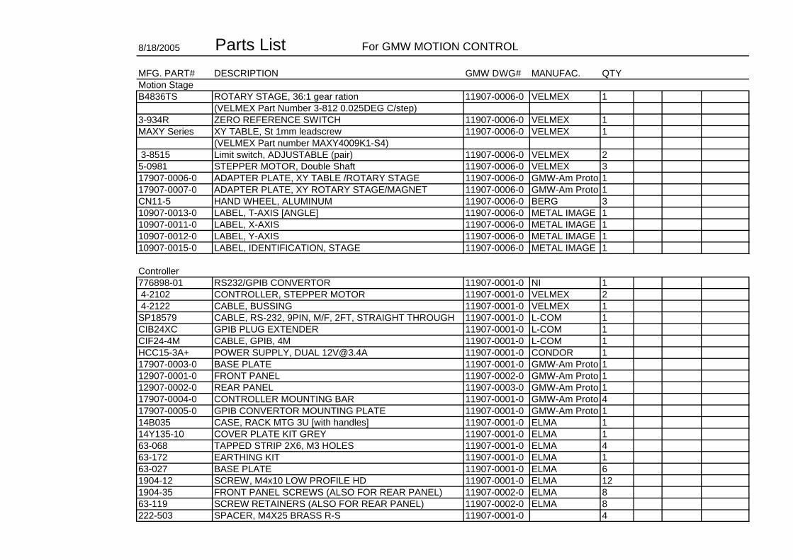
8/18/2005 Parts List For GMW MOTION CONTROL
MFG. PART# DESCRIPTION GMW DWG# MANUFAC. QTYMotion StageB4836TS ROTARY STAGE, 36:1 gear ration 11907-0006-0 VELMEX 1
(VELMEX Part Number 3-812 0.025DEG C/step)3-934R ZERO REFERENCE SWITCH 11907-0006-0 VELMEX 1MAXY Series XY TABLE, St 1mm leadscrew 11907-0006-0 VELMEX 1
(VELMEX Part number MAXY4009K1-S4) 3-8515 Limit switch, ADJUSTABLE (pair) 11907-0006-0 VELMEX 25-0981 STEPPER MOTOR, Double Shaft 11907-0006-0 VELMEX 317907-0006-0 ADAPTER PLATE, XY TABLE /ROTARY STAGE 11907-0006-0 GMW-Am Proto 117907-0007-0 ADAPTER PLATE, XY ROTARY STAGE/MAGNET 11907-0006-0 GMW-Am Proto 1CN11-5 HAND WHEEL, ALUMINUM 11907-0006-0 BERG 310907-0013-0 LABEL, T-AXIS [ANGLE] 11907-0006-0 METAL IMAGE 110907-0011-0 LABEL, X-AXIS 11907-0006-0 METAL IMAGE 110907-0012-0 LABEL, Y-AXIS 11907-0006-0 METAL IMAGE 110907-0015-0 LABEL, IDENTIFICATION, STAGE 11907-0006-0 METAL IMAGE 1
Controller 776898-01 RS232/GPIB CONVERTOR 11907-0001-0 NI 1 4-2102 CONTROLLER, STEPPER MOTOR 11907-0001-0 VELMEX 2 4-2122 CABLE, BUSSING 11907-0001-0 VELMEX 1SP18579 CABLE, RS-232, 9PIN, M/F, 2FT, STRAIGHT THROUGH 11907-0001-0 L-COM 1CIB24XC GPIB PLUG EXTENDER 11907-0001-0 L-COM 1CIF24-4M CABLE, GPIB, 4M 11907-0001-0 L-COM 1HCC15-3A+ POWER SUPPLY, DUAL [email protected] 11907-0001-0 CONDOR 117907-0003-0 BASE PLATE 11907-0001-0 GMW-Am Proto 112907-0001-0 FRONT PANEL 11907-0002-0 GMW-Am Proto 112907-0002-0 REAR PANEL 11907-0003-0 GMW-Am Proto 117907-0004-0 CONTROLLER MOUNTING BAR 11907-0001-0 GMW-Am Proto 417907-0005-0 GPIB CONVERTOR MOUNTING PLATE 11907-0001-0 GMW-Am Proto 114B035 CASE, RACK MTG 3U [with handles] 11907-0001-0 ELMA 114Y135-10 COVER PLATE KIT GREY 11907-0001-0 ELMA 163-068 TAPPED STRIP 2X6, M3 HOLES 11907-0001-0 ELMA 463-172 EARTHING KIT 11907-0001-0 ELMA 163-027 BASE PLATE 11907-0001-0 ELMA 61904-12 SCREW, M4x10 LOW PROFILE HD 11907-0001-0 ELMA 121904-35 FRONT PANEL SCREWS (ALSO FOR REAR PANEL) 11907-0002-0 ELMA 863-119 SCREW RETAINERS (ALSO FOR REAR PANEL) 11907-0002-0 ELMA 8222-503 SPACER, M4X25 BRASS R-S 11907-0001-0 4

RN-4-250A SPACER, 6.35X6.25 NYLON SPC 11907-0001-0 4239001 FUSE LINK 1.0A SLO BLO LITTLEFUSE 11907-0001-0 2239002 FUSE LINK 2.0A SLO BLO LITTLEFUSE 11907-0001-0 27043020305 POWER CORD SET, PANEL COMPONENT (USA) 11907-0001-0 110907-0004-0 LABEL, MASTER CONTROLLER 11907-0001-0 METAL IMAGE 110907-0005-0 LABEL, SLAVE CONTROLLER 11907-0001-0 METAL IMAGE 110907-0006-0 LABEL, CONTROLLER 11907-0001-0 METAL IMAGE 110907-0001-0 LABEL, IDENTIFICATION, CONTROLLER 11907-0002-0 METAL IMAGE10907-0002-0 LABEL, INPUT/OUTPUT 11907-0003-0 METAL IMAGE 110907-0003-0 LABEL, SPECIFICATION 11907-0003-0 METAL IMAGE 182710070 POWER SWITCH 11907-0002-0 INTERPOWER 183544010 POWER FILTER/VOLTAGE SELECTOR MODULE 11907-0003-0 INTERPOWER 1CGP-3 GROMMET EDGING STRIP 11907-0003-0 SPC A/R
Optional Z Stage: 3-8515 LIMIT SWITCH 11907-0006-0 VELMEX 1 5-0981 STEPPER MOTOR, Double Shaft 11907-0006-0 VELMEX 1MA Series Linear Slide, Std 1mm leadscrew 11907-0006-0 VELMEX 1
(VELMEX Part:MA4006K1-S4) 11907-0006-0CN11-5 HANDWHELL, ALUMINUM 11907-0006-0 BERG17907-0008-0 ADAPTOR PLATE, Y SLIDE TO Z SLIDE 11907-0006-0 GMW-Am Proto 117907-0009-0 ADAPTOR PLATE, Z SLIDE TO ROTARY STAGE 11907-0006-0 GMW-Am Proto 117907-0010-0 SPACER BAR, Z SLIDE, pair 11907-0006-0 GMW-Am Proto 1 pair10907-0014-0 LABEL, Z-AXIS 11907-0006-0 METAL IMAGE 1
FastenersSHCS FLAT HD, 10-32 X 5/8" S/S 11907-0006-0 4SHCS FLAT HD, 10-32 X 1/2" S/S 11907-0006-0 4SHCS 1/4 X 3/4" S/S 11907-0006-0 3SHCS M3 X 8 S/S 11907-0006-0 4WASHER, FLAT M3 S/S 11907-0006-0 4WASHER, INTERNAL LOCK M3 S/S 11907-0006-0 4SHCS, 10-32 X 5/8" S/S 11907-0006-0 4SHCS, 10-32 X 1 1/8" S/S 11907-0006-0 4SCREW, 4-40 X 3/16" PAN HD S/S 11907-0001-0 4WASHER, M4, INTERNAL LOCK S/S 11907-0001-0 8WASH, M4, FLAT S/S 11907-0001-0 8NUT, HEX M4 S/S 11907-0001-0 8SCREW, M3 X 16 PAN HD S/S 11907-0001-0 4SCREW, M4 X 8 PAN HD S/S 11907-0001-0 8SCREW, M4 X 12 PAN HD S/S 11907-0001-0 12