Embed Size (px)
Citation preview

TSL4186E, Issue 1 February 1998
User’sHandbook
4000 Series Diesel
4016 TAG1
4016 TAG2
http://www.brizmotors.ru/equipment/ctm/

DIESEL ENGINE DATA
http://www.brizmotors.ru/equipment/ctm/sp.1845/ 11
For full technical data please refer to the Product Information Manual.
Type: Water-cooled, turbocharged, charge cooled, industrial diesel engine.
RANGE 4012 4016
Cycle 4 stroke 4 stroke
No. of cylinders 12 16
Configuration V-form V-form
Bore 160 mm 160 mm
Stroke 190 mm 190 mm
Total swept volume 45,84 litres 61,123 litres
Compression ratio 13,6:1 13,6:1
Rotation Anti-clockwise looking on flywheel end
Firing order1A-6B-5A-2B-3A-4B-
6A-1B-2A-5B-4A-3B
1A-1B-3A-3B-7A-7B-5A-5B-
8A-8B-6A-6B-2A-2B-4A-4B
Valve Timinginlet valve opens 60° BTDC
inlet valve closes 46° ABDC
exh valve opens 46° BBDC
exh valve closes 60° ATDC
Cylinder numbering Cylinder 1 furthest from flywheel
Cylinders designated A are on the right hand side of the engine, when viewed from the fly-wheel end and cylinders
designated B are on the left hand side of the engine.
Valve Clearances exhaust 0,40 mm (0,016”)
(Engine cold) inlet 0,40 mm (0,016”)
Valve dia. (mm) inlet and exhaust 48 48
(52 on 4012TAG1/2 AND 4016TAG1/2)
Valve Timing See Workshop Manual Sections U4 and U5
Injection Timing See engine nameplate
Piston Speeds Engine r/min m/s (ft/min)
1000 6,33 (1247)
1200 7,60 (1496)
1500 9,50 (1870)
1800 11,40 (2244)
Fig. B
‘A’ BANK ‘B’ BANK

DIESEL ENGINE DATA
12 http://www.brizmotors.ru/equipment/ctm/sp.1845/
TYPICAL COOLING SYSTEM
* Engine only
** Engine with heat exchanger
FUEL SYSTEM
GOVERNORS
4006 4008
Approved Coolants) See page 21
Total water capacity Ltrs Gals Spec Ltrs Gals Spec
200 44 TAG 255 56.1 TAG
232 51 TAG1 316 70 TAG1
232 51 TAG2 316 70 TAG2
185 40 TWG 95 21 TWG*
205 45 TWG2 95 21 TWG2*
82 18 TEG** 108 23.7 TEG**
Max radiator top tank temperature 93°C
Max water temperature into engine 80°C
Thermostat opening temperature 71°C
System pressure 0.5 to 0.7 bar
4012 4016
Approved fuels See page 20
Minimum size fuel tank 14000 litres (3000 gal.) 18000 litres (4000 gal.)
Relief valve setting 310 kPA (45 psi)
Inferior nozzle pressure 225-235 atm
Injection equipment Lucas-Bryce unit injector
Filter/water separator Spin-on expandable canister(s)
Fuel lift pump Maximum suction lift 1 metre
Fuel flow 20.457 litre/min. (4.5 gpm) @ 1800 r/min
4012 4016
Type Electronic Electronic
Type Hydraulic Hydraulic

DIESEL ENGINE DATA
http://www.brizmotors.ru/equipment/ctm/sp.1845/ 13
LUBRICATION SYSTEM
INDUCTION SYSTEM
EXHAUST SYSTEM
FLYWHEEL
FLYWHEEL HOUSING
4012 4016
Recommended oil See pages 19 and 20
Type of system Wet sump, external engine mounted oil pump
Total oil capacity (including cooler and filter) 178 litre (39.2 gal) 238 litre (53 gal)
Sump capacity (dipstick)
Min. 136 litre (30 gal) 147 litre (33 gal)
Max. 159 litre (35 gal) 214 litre (47 gal)
Crankcase pressure (max) 25 mm (1”) water gauge
Lubricating oil temperature max. to bearings 105°C
Lubricating oil pressure at 80°C temp. to bearings 0.34 mPa
Max. oil temperature in sump 115°C
Min. oil pressure (1500 rpm)(at filter head) 200 kPa (30 lb/in²)
Oil filter Disposable canister type
Oil pump location ‘A’ Bank
4012 4016
Air cleaners (earlier)
(current)
Twin vertical air cleanersTwin horizontal air cleaners
Type Paper element
Air restriction indicator setting 380 mm H20
Turbochargers x2 off x4 off
4012 4016
Manifold Type Dry or water cooled
Exhaust outlet flange Vertical (Twin)
Mating flange See Installation Manual
Max. exhaust back pressure See Product Information Manual
Max. exhaust temperature
4012 4016
Drive size SAE 18”
SAE 21” Optional
4012 4016
SAE size 00

DIESEL ENGINE DATA
14 http://www.brizmotors.ru/equipment/ctm/sp.1845/
TYPICAL DRY WEIGHT
HOLDING DOWN BOLT HOLES
ELECTRICAL SYSTEM
4012 4016
Dry weight (engine) 4360 kg 4012TAG 5500 kg 4016TAG
4360 kg 4012TAG1 5750 kg 4016TAG1
4400 kg 4012TAG2 5750 kg 4016TAG2
4975 kg 4012TWG 5940 kg 4016TWG/2
5315 kg 4012TWG2 5820 kg 4016TEG
4680 kg 4012TEG2
Dry weight engine & tropical radiator 5280 kg 4012TAG 6900 kg 4016TAG
5760 kg 4012TAG1 8010 kg 4016TAG1
5800 kg 4012TAG2 8010 kg 4016TAG2
4995 kg 4012TWG
5315 kg 4012TWG/2
Dry weight engine & heat exchanger 4860 kg 4012TEG 6000 kg 4016TEG
4012 4016
Hole dia. (Engine feet) 22 mm
No. off 8
Hole dia. (Radiator feet) 18 mm x 6 4012TAG 22 mm x 6 4016TAG/2
Turbochargers 22 mm x 6 4012TAG2
22 mm x 6 4012TWG/1
4012 4016
Voltage 24V
Alternator Belt Driven
Alternator output 30A
Starter motor
Single CAV
(Earlier Engines)
Twin Prestolite
(Current Engines)
Twin Prestolite
No. of teeth (gear ring)144 (Early Engines)
156 (Current Engines)
156
No. of teeth (starter pinion) 12
Battery (lead acid) 24V DC (2 x 12V)
Capacity down to 0°C (32°F) 286 Ah
http://www.brizmotors.ru/equipment/ctm/

DIESEL ENGINE DATA
http://www.brizmotors.ru/equipment/ctm/sp.1845/ 15
PROTECTION EQUIPMENT
Before resetting protection equipment, it must be established whether special settings (forthat individual engine) have been specified in the engine sales contract. This is particularlyimportant with ALL high water temperature settings, and ALL Cogen applications.
Standard settings for protection equipment are as follows:-
Caution: The above standard settings do not supersede any settings specified in the enginesales contract.
AIR STARTING
INSTRUMENT PANEL (ENGINE MOUNTED)
COOLANT JACKET HEATING
Alarm Shutdown
High Oil temperature (in sump) 110°C 115°C
Low oil pressure 2.06 bar (30 lb/in²) 1.93 bar (28 lb/in²)
High water temperature
71°C Thermostat 91°C 96°C
85°C Thermostat 96°C 101°C
96°C Thermostat 100°C 105°C
Overspeed15% above max. running speed
(Except 1800 r/min which is 7%)
4012 4016
Air starter See Installation Manual
Air starter pressure 150 lb/in2 (10.34 bar)
Compressed air supply 170 lb/in2 (11.72 bar)
Normal Operation
Oil pressure Between 276-413 kPa (40-60 lb/in²)
Oil temperature Between 80-90°C (176-194°F)
Water temperature Between 65-85°C (149-185°F)
Exhaust temperature See Product Information Manual
4012 4016
Heater 2 x 4 kW
Voltage 210-250V ac
http://www.brizmotors.ru/equipment/ctm/

TORQUE SETTINGS
16 4012/4016 Diesel, February 1997
NOTE: * Bolt heads and threads must be lubricated with clean engine oil.
** Cylinder head bolts to be lubricated under the heads, under the washers and onthe threads with PBC (Poly-Butyl-Cuprysil) grease. Important: See Workshop ManualSection R11 before fitting. However, dry threads are required for connecting rod bolts andthe raw water pump shaft nut, but all other threads only to be lubricated with clean engineoil and care must be taken NOT to oil the heads or faces.
TORQUE SETTINGS
CYLINDER HEAD GROUP lbf.ft Nm
Cylinder head bolt ** (early type) M24 550 750
Cylinder head bolt ** (later waisted type) M24 530 720
Rocker shaft capscrew/nut M16 90 120
Rocker adjuster nuts inlet/exhaust M12 35 50
Rocker adjuster nuts pump injectors M14 50 70
Injector clamp capscrews M12 70 95
Bridge piece adjuster nuts M10 25 35
Injector clamp to cylinder head capscrews M12 70 95
Rocker box bolts M10 35 50
Air manifold bolt M10 35 50
Exhaust manifold bolts M10 50 70
Exhaust bellows to exhaust manifold (16 cyl only)
prevailing torque bolts / nuts M10 45 60
Exhaust Y piece (16 cyl only) prevailing torque bolts M10 38 50
Schwitzer turbocharger 'V'-band clamp nuts M8 8 11
Sandwich plate retaining capscrews M10 35 50
CRANKCASE AND CRANKSHAFT GROUPS
Main bearing bolts * See Section W4 M24 580 786
Lateral capscrews, main bearing caps for sequence M16 124 168
Bolts sump to crankcase M10 40 54
New connecting rod bolts (must be fitted with dry threads) M16 210 285
Inspection covers M10 35 50
Viscous damper bolts M16 250 340
Flywheel bolts See Section X3 for sequence M16 250 340
Front drive adaptor bolts (12 cylinder engines only) M16 250 340
Front drive adaptor bolts (16 cylinder engines only) M20 380 520
Balance weight bolts M16 250 340
Crankshaft pulley bolts M16 250 340
Piston cooling jet screws M10 20 27
Flywheel housing bolts M10 35 50
Lifting bracket Durlock screws M10 50 70
WARNING IT IS ESSENTIAL THAT THE CORRECT LENGTH OF SCREW ORBOLT IS USED. INSUFFICIENT LENGTH MAY RESULT IN THE
THREAD BEING STRIPPED, WHEREAS TOO LONG A THREAD MAY RESULT INBOTTOMING IN A BLIND HOLE, OR CATCHING ON ADJACENT COMPONENTS.

TORQUE SETTINGS
4012/4016 Diesel, February 1997 17
LUBRICATING OIL PUMP lbf.ft Nm
Bolts, pump housing to gearcase plate M10 35 50
Thin nut, gear to drive shaft M30 175 237
CAMSHAFT GROUP
Camshaft gear bolt M12 110 150
Camshaft thrust plate bolt M10 35 50
Camshaft follower housing bolt M10 35 50
Idler gear hub bolts M10 35 50
WATER PUMP
Water pump gear nut M24 170 230
Water header to oil cooler bolts M10 35 50
Water pump to gearcase bolts M10 35 50
Raw water pump gear securing nut, dry thread M35 180 244
ENGINE FEET
Engine feet to base frame bolts M20 350 475
Engine feet to cushion feet bolts M16 160 215
Engine feet to gearcase and suspension plate bolt M12 70 95
GOVERNOR
Control shaft mounting plate bolt M10 35 50
FAN
Fan driven pulley taper lock bush screws 1/2" BSW 35 50
Fan driven pulley taper lock bush screws 5/8" BSW 65 90
ALTERNATOR
Drive pulley taper lock bush screw 3/8" BSW 15 20
FUEL PUMP/INJECTORS
Injector capscrew clamp to cylinder head, early engines M10 50 70
Injector capscrew clamp to cylinder head, later engines M12 70 95
Injector nozzle nut to holder M27 150 203
Fuel pump control linkage screw 2BA 6 8
Unit injector control lever capscrews M5 6 8
FLEXIBLE COUPLING
Flexible coupling cover screw M12 or 1/2" UNC 47 64
Coupling driving flange screws (coupling size 2.15) M12 or 1/2" UNC 47 64
Coupling driving flange screws (coupling size 3.86) M16 or 5/8" UNC 114 155
http://www.brizmotors.ru/equipment/ctm/
TORQUE SETTINGS
18 4012/4016 Diesel, February 1997
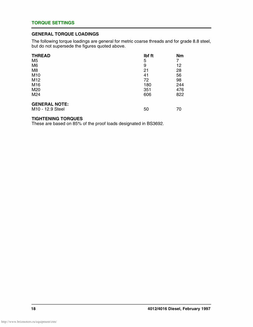
GENERAL TORQUE LOADINGS
The following torque loadings are general for metric coarse threads and for grade 8.8 steel,but do not supersede the figures quoted above.
THREAD lbf ft NmM5 5 7M6 9 12M8 21 28M10 41 56M12 72 98M16 180 244M20 351 476M24 606 822
GENERAL NOTE:M10 - 12.9 Steel 50 70
TIGHTENING TORQUESThese are based on 85% of the proof loads designated in BS3692.
http://www.brizmotors.ru/equipment/ctm/

LUBRICATING OIL RECOMMENDATIONS
http://www.brizmotors.ru/equipment/ctm/sp.1845/ 19
QUANTITY OF OIL
TYPE OF OIL
The industrial diesel engine should be lubricated with a good quality oil conforming to APICD or CCMC D4 specifications. All the major oil companies formulate oils to the abovespecifications.
VISCOSITY OF OIL
Use oil of:
SAE10W/30 in starting temperatures below -15°C (without sump heater)
SAE10W/40 in starting temperatures from -15°C to 0°C
SAE30 in starting temperatures from 0°C to 32°C or Mobil Devlac Super
SAE40 in starting temperatures above 32°C 1300 SAE 15W/40
OIL CHANGE PERIODS
For normal operation of the engine the oil should be changed every 250 hours or annuallywhichever is the sooner.
Under certain circumstances where a centrifugal oil filter is fitted to the engine and an oilanalysis programme has been carried out with the oil supplier over a period of 1000 hoursof engine operation, it may be possible to extend the oil change period up to maximum of350 hours.
To achieve this extended oil change period, a centrifugal oil filter must be fitted and cleanedevery 250 hours between routine oil changes, and at every oil change point i.e. 350 hoursmaximum.
As the oil deteriorates it is essential that the following parameters must not be exceeded atthe oil change point:
1 The viscosity of the oil must not increase by more than 10cSt at 100°C.
2 The total base number of the oil should not reduce to less than 50% of the value of newoil.
3 The flash point of the oil should exceed 180°C.
4 The water content of the oil must not exceed 1%.
5 The fuel content of the oil must not exceed 1%.
6 Oil samples should be taken from the mean sump oil level of the engine.
Sump Capacity Dipstick 4012 4016
Minimum 136 litre(30 gal) 147 litre (33 gal)
Maximum 159 litre (35 gal) 214 litre (47 gal)

LUBRICATING OIL RECOMMENDATIONS
20 http://www.brizmotors.ru/equipment/ctm/sp.1845/
ENGINE OPERATIONExcessive periods of idling or repeated cold starts should be avoided, as they will causeexcessive dilution of the oil by fuel, requiring more frequent oil changes and dangerouslylowering the flash point of the oil.
Should there be a lubricating oil supply problem, or if the fuel being used contains more than0.5% sulphur, Perkins Engines (Stafford) Limited must be consulted to give advice inselecting a suitable grade.
The following list gives details of some of the oils that meet the required specifications. Notethat the brand names may change as oils are upgraded or reformulated.
An up-to-date list is maintained by Perkins Engines (Stafford) Limited of major oil companiesproducts and information, which can be obtained from Perkins Engines (Stafford) ServiceDepartment.
APPROVED INDUSTRIAL OIL A1 SPECIFICATIONS BSEN 590(Suitable for fuel to Class A2 specifications BS2869 Part 2).
Oil Company TypeCASTROL CRH/RX SuperELF Multiperfo XCKUWAIT OIL Co Q8 T400MOBIL Delvac 13
Delvac Super 1300 (15W/40)SHELL Rimula XESSO Essolube XD 3+TEXACO Ursa Super LA
WARNING FAILURE TO COMPLY WITH THESE INSTRUCTIONS WILLINVALIDATE THE WARRANTY OFFERED WITH THE ENGINE, AS
IT MAY RESULT IN ENGINE DAMAGE.

COOLANT
http://www.brizmotors.ru/equipment/ctm/sp.1845/ 21
ENGINE COOLING SYSTEM
The cooling system of an engine containsmany different materials e.g. cast iron,aluminium, copper, solder, rubber (varioustypes). To prevent deterioration of thesematerials, it is essential to use a very goodquality coolant. Untreated water is notsuitable. It is essential that the water istreated with an additive that gives thenecessary protection.
WATER QUALITY
The water to be mixed with the additive musthave the following characteristics:
Chlorides less than 80 PPMV
(PPMV = parts per million by volume)
Sulphates less than 80 PPMV
Total hardness less than 200 PPMV
pH of water between 7 to 7.5
(neutral to slightly alkaline)
ADDITIVES TO WATER
Due to the complexity of the cooling systemit is necessary to use an additive thatcontains a balanced package of corrosioninhibitors.
To achieve the required solution a 50/50 mixof Shell Safe Premium antifreeze with watershould be used at all times, even in areaswhere frost is unlikely.**
The 50/50 mixture will give frost protectiondown to -35°C. In areas where Shell SafePremium is not available contact PerkinsEngines (Stafford) Limited for advice on arecommended alternative.
Under no circumstances should an additivecontaining nitrites, borates, phosphates,chromates, nitrates, or silicates be used, asthey are not compatible with the materialsused in the cooling system.
When mixing the antifreeze with the wateralways follow the manufacturer'srecommendation to add the antifreeze in thecorrect proportion before introducing it intothe engine cooling system. Adding water toantifreeze can lead to the formation of a gelin the mixture, which can cause blockage ofthe water passages and subsequent localoverheating.
MAINTENANCE OF COOLANT
The water/antifreeze mixture should beregularly replaced in operating engines atleast once a year.
In engines used for standby duty it isessential to maintain the water/antifreezemixture at the correct alkalinity level i.e. thepH should not increase above 7.5. Ahydrometer only shows the proportion ofethylene glycol, not the degree of corrosionprotection.
4012TWG2 only to this rule is when twosection radiators are used in conjunctionwith charge air coolers under tropicalconditions. It may be necessary to reducethe antifreeze content of the coolant from50% to 10% to achieve an adequate heattransfer coefficient.
WARNING ALWAYS STOP THEENGINE AND ALLOW
THE PRESSURISED SYSTEM TO COOLBEFORE REMOVING FILLER CAP.AVOID SKIN CONTACT WITHANTIFREEZE BY WEARING HAND, ETC.
WARNING FAILURE TO FOLLOWTHE ABOVE
RECOMMENDATIONS MAY RESULT INDAMAGE TO THE ENGINE, AND WILLINVALIDATE THE ENGINE WARRANTY.

FUEL SPECIFICATION
22 http://www.brizmotors.ru/equipment/ctm/sp.1845/
Fuel should be wholly hydrocarbon oil derived from petroleum, with which small quantitiesof additives may be incorporated for the improvement of ignition or other characteristics andshould conform to British Standard Specification 2869. Class A1 or A2.
If fuels other than the above classes are considered, the operator must consult PerkinsEngines (Stafford) Limited, and ensure that a suitable grade of lubricating oil is used.
BS2869 REQUIREMENTS FOR ENGINE FUEL
Property Class A1 Class A2
Viscosity, Kinematic at 40°C, cSt *
Min. 1.5 1.5
Max. 5.0 5.5
Cetane number, min. 50 45
Carbon residue, Ramsbottom on 10% residue, % (m/m), max. 0.20 0.20
Distillation, recovery at 350°C, % (V/V), min. 56°C 56°C
Sulphur content, % (V/V), max. 0.05 0.05
Sediment, % (m/m), max. 0.01 0.01
Ash, %(m/m), max. 0.01 0.01
Sulphur content, % (m/m), max. 0.30++ 0.50++
Copper corrosion test, max. 1 1
Cold filter plugging point C, max.
Summer (March/September inclusive) -4 -4
Winter (October/February inclusive) -15 -12
* cSt = 1 mm²/s.
++ This limit is set in accordance with the legislative requirements for gas oil of the 'CouncilDirective (75/716/EEC of the European Economic Community) on the approximation of thelaws of Member States relating to the sulphur content of certain liquid fuels'.
In countries where this legislation does not apply, it is permissible to run 4000 Seriesengines on fuels with up to 1.0% sulphur. (See page 20 "Engine Operation").
ENGINE FUELS
1 The two classes of fuel specified in the table are marketed specifically as oil enginefuels. Class A1 is of higher quality and is intended primarily as an automotive dieselfuel, whilst Class A2 is intended as a general purpose diesel fuel. Classes A1 and A2are distillate grades and are so specified as to prevent the inclusion of residuum.
2 The specifications for Classes A1 and A2 include limits for cold filter plugging pointchosen to cover seasonal requirements in the United Kingdom.
3 Ignition quality is specified in terms of cetane number, but the calculated cetane indexis referred to as an alternative for routine purposes with fuels not containing ignitionimprover additives.
NOTE: If local supply problems dictate that fuels which fall outside the above specificationare to be used, our Service Department must be consulted prior to use.
http://www.brizmotors.ru/equipment/ctm/

OPERATING INSTRUCTIONS
http://www.brizmotors.ru/equipment/ctm/sp.1845/ 23
PREPARING FOR INITIAL STARTFILLING THE ENGINE WITH OIL
Remove the drain plug to ensure that thesump is clean and empty. Refit and tightenthe plug. Remove the oil filler situated on theleft hand side of the crankcase, by rotatingthe T-bar anti-clockwise and pulling up (Fig.1). Fill the sump to the maximum mark onthe dipstick with the appropriate grade andquantity of oil (see page 19 & 20).
NOTE: If the engine has been overhauledensure that, with the governor in the stopposition, the pump injectors are set in the'NO FUEL' position.
PRIMING THE TURBOCHARGERS ONENGINES FITTED WITH THEELECTRONIC GOVERNOR
Before starting the engine for the first time, orif it has stood idle for more than threemonths, the turbocharger bearings shouldbe primed. To prime the turbocharger, theengine needs to be motored over on thestarter. In order that the engine does not runup to speed when operating the key switch(i.e. energising the stop solenoids) it will benecessary to hold the governor lever in thestop position (see Fig. 13) but ensure thatthe air shut-off valves have been manuallyset to the run position (see Fig. 12).
Key
(Fig. 2 & Fig. 3)
1. Electronic plug
WARNING NEVER OPERATETHE ENGINE WHEN
THE OIL LEVEL IS BELOW THEMINIMUM MARK OR ABOVE THEMAXIMUM. ALWAYS WEARPROTECTIVE GLOVES WHENHANDLING ENGINE OIL.
Fig. 1
Fig. 2
1
Fig. 3
1
http://www.brizmotors.ru/equipment/ctm/

OPERATING INSTRUCTIONS
24 http://www.brizmotors.ru/equipment/ctm/sp.1845/
For earlier engines not fitted with a stoplever, disconnect the battery leads andremove the electric plug from the governorby unscrewing the locking collar and pullingthe plug out of its socket. (See Fig. 2 & Fig.3).
Operate the starting control or key switchand motor the engine over on the starter untilan oil pressure of approximately 40 kPa (5 lb/in²) is indicated on the pressure gauge.Continue for a further 10 seconds to ensurethat the oil has reached the turbochargers,and stop the engine by releasing the startcontrol. Disconnect the battery leads andreconnect the electric plug in the actuator.Reconnect the battery leads.
PRIMING THE TURBOCHARGERS ONENGINES FITTED WITH REGULATEURSEUROPA OR HYDRAULIC GOVERNORS
Let the engine run without load for about 5minutes ensuring the lubricating oil hasreached the turbochargers.
PRIMING THE TURBOCHARGERS ONENGINES FITTED WITH A WOODWARDTYPE UG10 OR 3161 HYDRAULICGOVERNOR
NOTE: It is recommended that for initialstarting of new or overhauled engines, thatthe load is disengaged, with the governorspeed control lever in the minimum speedposition, the shutdown solenoid in the STOPposition and the air shut-off valves manuallyset to the run position (see Fig. 4 and Fig.11).
Check the oil level by means of the sightgauge. If necessary, add new SAE 30 orSAE15W/40 engine oil (after lifting the fillercap) to bring the oil up to the correct level(see Fig. 2). Ensure that the fuel supply tothe engine is turned off.
Key
(Fig. 4)
1 Low speed stop
2 Oil filler
3 Compensation adjustment
4 Oil drain plug
5 Compensating needle valve
6 High speed stop
7 Oil level gauge
With the speed control unit set in the idlingposition, (for generator duty the governorminimum and maximum speed stops arefactory set) ensure that the governor speedlever is in the minimum speed position. Turnthe key in the instrument panel from the stopposition to the start position and motor theengine over on the starter until the oilpressure gauge registers approximately 40kPa (5 lb/in²). Continue cranking for a further10 seconds to ensure that the oil hasreached the turbochargers.
WARNING THE OPERATORMUST BE IN A TO
PRESS THE EMERGENCY STOPBUTTON IN THE EVENT OF APROTECTION EQUIPMENT FAILURE.
Fig. 4
12
3
4
5
6
7

OPERATING INSTRUCTIONS
http://www.brizmotors.ru/equipment/ctm/sp.1845/ 25
BATTERIES (SUPPLIED DRY CHARGED)See Installation Manual
Check the level of electrolyte in each batterycell which should be approximately 8 mmabove the plates. Using a hydrometer, checkthat the batteries are fully charged. A fullycharged battery will have a specific gravity of1.27 to 1.285, assuming the air temperatureis below 32°C. For higher temperatures thespecific gravity will be 1.24 to 1.255. Whentopping up the batteries always use puredistilled water and always replace the plugsafter filling.
WARNING HAND PROTECTIONMUST BE WORN
WHEN CHECKING THE BATTERYELECTROLYTE. NEVER CHECK WITH ANAKED FLAME.
WARNING NEVER CONNECT ABATTERY INTO THE
SYSTEM WITHOUT FIRST CHECKINGTHE POLARITY AND VOLTAGE. NEVERDISCONNECT THE BATTERY WHILSTTHE ENGINE IS RUNNING. NEVERFLASH CONNECTIONS TO CHECK FORCURRENT FLOW.

OPERATING INSTRUCTIONS
26 http://www.brizmotors.ru/equipment/ctm/sp.1845/
PRIMING AND VENTING THE FUELSYSTEMAS FITTED ON THE EARLIER 12& 16 CYLINDER ENGINES.
Loosen the union nut on the fuel feed pipefrom the fuel filter, Fig. 5.
Operate the priming pump by pressing therubber button Fig. 6. Continue priming untilair free fuel flows from the union. Re-tightenthe union nut.
Then slacken off the vent plugs located atthe opposite to flywheel end of 'A' and 'B'bank fuel return rails, Fig. 7 and continuepriming until air free fuel flows. Tighten thevent plugs.
When priming a fuel system fitted withchangeover fuel filters, undo the left handbleed screws 'L' (see Fig. 8). Operate thepriming pump by pressing the rubber button(see Fig. 6), until air free fuel flows from thebleed screws. Retighten the left bleedscrews 'L'. Repeat the above operation withthe right hand bleed screws 'R' until all fourfilters have been primed with fuel.
Slacken off the vent plugs located at the frontend of both fuel return rails (see Fig. 7) andcontinue priming until air free fuel flows.Retighten the vent plugs.
Key
(Fig. 6 & Fig. 7)
1 Priming pump
2 Strainer
3 Vent plug
Fig. 5
Fig. 6
1
2
Fig. 7
3
Fig. 8
L LR R

OPERATING INSTRUCTIONS
http://www.brizmotors.ru/equipment/ctm/sp.1845/ 27
PRIMING AND VENTING THE FUELSYSTEM AS FITTED ON LATER 12 & 16CYLINDER ENGINES
Loosen the union nut on the fuel feed pipe tothe front cylinder head on the fuel rail Fig. 9.
NOTE: The fuel system should not be bledfrom the water trap/sedimenter filter (iffitted), since this is on the suction side of thelift pump. Fig. 10. However, it is important todrain the water from this unit periodically. Donot operate the priming pump but unscrewthe valve at the bottom of the filter about 4turns until it drops down about 25 mm (1inch). Allow the water to drain out and thenscrew the valve back in until it is hand tight.
Operate the priming pump by pressing therubber button Fig. 10. Continue priming untilair free fuel flows from the union. Re-tightenthe union nut.
FILLING THE COOLING SYSTEMS
The use of non-inhibited water is notrecommended owing to chemical reactionswhich can result in corrosion and furring-upof the cooling system. A solution of eitheruniversal anti-freeze or corrosionpreventative and water must be used. Referto page 21.
After installation and before the first startremove the radiator cap, see Fig. 11. Fill thecooling system and run the engine off-loadfor one minute to ensure that the system iscompletely filled. Stop the engine and top upthe system to within 25 mm (1") of the top ofthe filler neck then replace the cap. Shouldthe engine be fitted with water cooledexhaust manifolds, these will need bleeding.(Older engines without vent pipes only).(See Workshop Manual Section Q3).
Key
(Fig. 10 & Fig. 11)
1 Normal fuel flow
2 Priming circuit
3 Water trap/sedimenter
4 Drain valve - DO NOT open whenengine running
5 Radiator cap
WARNING THE COOLINGSYSTEM IS
PRESSURISED - DO NOT REMOVE THEFILLER CAP FROM THE RADIATORWHILE THE ENGINE IS HOT. HANDPROTECTION MUST BE WORN.
Fig. 9
Fig. 10
12
3
4
Fig. 11
5

OPERATING INSTRUCTIONS
28 http://www.brizmotors.ru/equipment/ctm/sp.1845/
INITIAL STARTING OF THE ENGINEWHEN FITTED WITH THE ELECTRONICGOVERNOR
With the load disengaged, ensure that thestop control on engine/panel is in the 'stop'position, and that the air shut-off valves havebeen manually set to the 'run' position (seeFig. 12) typical installation.
EARLIER ENGINES NOT FITTED WITHAN ENGINE STOP LEVER
Disconnect the battery leads and remove theelectric plug from the Heinzmann actuator byunscrewing the locking collar and pulling theplug out of its socket.
Press the emergency stop button to de-energise the stop solenoids, to prevent thegovernor levers moving into the 'run'position.
Reconnect the battery leads.
LATER ENGINES FITTED WITH ANENGINE STOP LEVER
In order to prevent the engine running up toits rated speed when operating the keyswitch, it will be necessary to hold the stoplever in the 'stop' position. Fig. 13.
Key
(Fig. 12 & Fig. 13)
1 Closed (stop)
2 Latched in (run)
3 Governor lever
4 Stop position
5 Run position
6 Solenoid energised
7 Solenoid de-energised
WARNING ALWAYS BE IN APOSITION TO
MANUALLY STOP THE ENGINE IN THEEVENT OF A MALFUNCTION BYOPERATING THE EMERGENCY STOPBUTTON.
Fig. 12
1
2
Fig. 13
3 4
6
7
5
http://www.brizmotors.ru/equipment/ctm/
OPERATING INSTRUCTIONS
http://www.brizmotors.ru/equipment/ctm/sp.1845/ 29
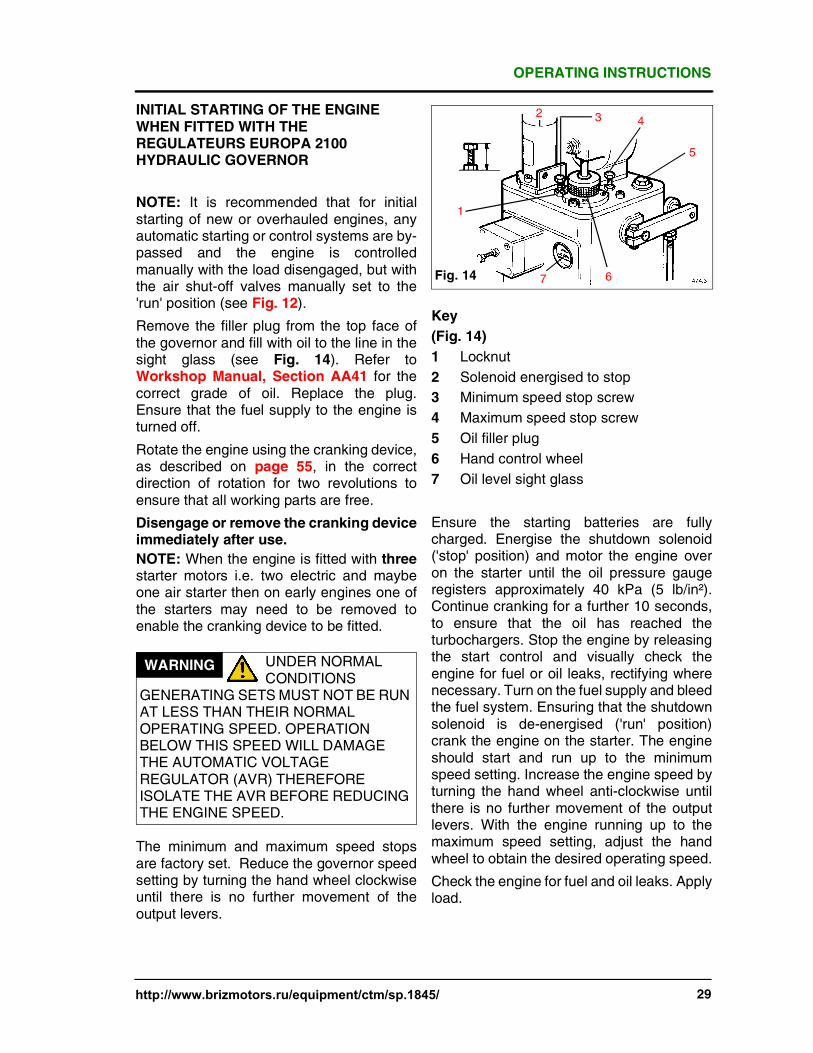
INITIAL STARTING OF THE ENGINEWHEN FITTED WITH THEREGULATEURS EUROPA 2100HYDRAULIC GOVERNOR
NOTE: It is recommended that for initialstarting of new or overhauled engines, anyautomatic starting or control systems are by-passed and the engine is controlledmanually with the load disengaged, but withthe air shut-off valves manually set to the'run' position (see Fig. 12).
Remove the filler plug from the top face ofthe governor and fill with oil to the line in thesight glass (see Fig. 14). Refer toWorkshop Manual, Section AA41 for thecorrect grade of oil. Replace the plug.Ensure that the fuel supply to the engine isturned off.
Rotate the engine using the cranking device,as described on page 55, in the correctdirection of rotation for two revolutions toensure that all working parts are free.
Disengage or remove the cranking deviceimmediately after use.
NOTE: When the engine is fitted with threestarter motors i.e. two electric and maybeone air starter then on early engines one ofthe starters may need to be removed toenable the cranking device to be fitted.
The minimum and maximum speed stopsare factory set. Reduce the governor speedsetting by turning the hand wheel clockwiseuntil there is no further movement of theoutput levers.
Key
(Fig. 14)
1 Locknut
2 Solenoid energised to stop
3 Minimum speed stop screw
4 Maximum speed stop screw
5 Oil filler plug
6 Hand control wheel
7 Oil level sight glass
Ensure the starting batteries are fullycharged. Energise the shutdown solenoid('stop' position) and motor the engine overon the starter until the oil pressure gaugeregisters approximately 40 kPa (5 lb/in²).Continue cranking for a further 10 seconds,to ensure that the oil has reached theturbochargers. Stop the engine by releasingthe start control and visually check theengine for fuel or oil leaks, rectifying wherenecessary. Turn on the fuel supply and bleedthe fuel system. Ensuring that the shutdownsolenoid is de-energised ('run' position)crank the engine on the starter. The engineshould start and run up to the minimumspeed setting. Increase the engine speed byturning the hand wheel anti-clockwise untilthere is no further movement of the outputlevers. With the engine running up to themaximum speed setting, adjust the handwheel to obtain the desired operating speed.
Check the engine for fuel and oil leaks. Applyload.
WARNING UNDER NORMALCONDITIONS
GENERATING SETS MUST NOT BE RUNAT LESS THAN THEIR NORMALOPERATING SPEED. OPERATIONBELOW THIS SPEED WILL DAMAGETHE AUTOMATIC VOLTAGEREGULATOR (AVR) THEREFOREISOLATE THE AVR BEFORE REDUCINGTHE ENGINE SPEED.
Fig. 14
2 3 4
5
67
1

OPERATING INSTRUCTIONS
30 http://www.brizmotors.ru/equipment/ctm/sp.1845/
NORMAL STARTING PROCEDUREWHEN FITTED WITH THEREGULATEURS EUROPA 2100GOVERNOR AND A WOODWARD TYPEUG10 OR 3161
Ensure that where possible the load is off.Set the engine switch to the 'run' position andpress the starter button, the engine shouldstart immediately and run up to full speed.
If the engine does not start within a fewseconds, do not keep the starter engaged,let the engine come to rest and begin again.Allow 15 seconds between start attempts. Ifthe engine fails to start after severalattempts, do not persist in motoring theengine but investigate the cause. Check oilpressure, for fuel and oil leaks and that theammeter in the instrument panel is showingcharge to the engine batteries. Allow theengine to run for 5 minutes. Checkinstruments are reading correctly. Applyload.
NORMAL STARTING PROCEDUREWHEN FITTED WITH THE HEINZMANNE16 AND WOODWARD PROACT IIELECTRONIC GOVERNOR
Operate the start control, which will energisethe solenoid and allow the governor lever tomove to the 'run' position Fig. 11, the engineshould then start immediately. Again checkthe oil pressure, for any fuel or oil leaks, andthat the ammeter in the instrument panel isshowing charge to the engine batteries.Allow the engine to run for five minutes,checking that instruments are readingcorrectly. Apply load.

OPERATING INSTRUCTIONS
http://www.brizmotors.ru/equipment/ctm/sp.1845/ 31
ENGINE SHUTDOWN
The engine is normally stopped by operatingan electric stop control via a key switch. Inthis case it is only necessary to turn the keyin an anti-clockwise direction which de-energises the stop solenoids to stop theengine. The solenoids remain de-energiseduntil the engine is started up again.
NOTE: For engines fitted with RegulateursEuropa 2100, Woodward UG 10 or 3161hydraulic governors, the 'stop' solenoids arebuilt into the governors and they areenergised to stop (ETS) the engine and de-energised shortly after the engine stops.
Should the engine stop due to the air shut-offvalves being operated, it is imperative thatthe cause of the fault be investigatedimmediately.
It is essential to allow the engine to run at noload for 3 - 5 minutes before stopping toallow the circulating lubricating oil to take theheat away from the bearings and shafts, etc.This is especially important withturbocharged engines where extremely hightemperatures are experienced within theturbocharger. Heat rise by suddenlystopping an engine on load can causeseizure of bearings and damage to oil seals.
NOTE: Excessive idling of the engine willresult in only partial burning of the fuel,causing high carbon build-up on injectornozzles, valves, piston rings, etc. Alsounburnt fuel will tend to wash thelubricating oil from cylinder bores anddilute the oil in the sump. This caneventually cause inefficient lubrication ofbearings and result in seizure.
WARNING DO NOT RUN THEENGINE AT LOW
SPEEDS OR LOADS. IF THE ENGINE ISNOT BEING USED SHUT IT DOWN.
http://www.brizmotors.ru/equipment/ctm/

LIGHT LOAD OPERATION & STANDBY GENERATING SETS
32
If an engine is operated on a load less than25-30% of its rated output, certain symptomswill be observed which may give cause forconcern.
The usual results of this operation areheavier than normal lubricating oilconsumption, and oil leaks from the air andexhaust manifolds. This condition isparticularly evident on stand-by generatorset applications where a weekly exercise onno load is the usual practice.
These phenomena are due to the fact that:
1 Turbocharger oil seals are not fullyeffective on light load which results in oilbeing delivered together with the air intothe engine air manifolds.
2 The cylinder temperatures are too low toensure complete burning of all the fueldelivered. This results in an unsightlydrip from the exhaust manifoldjunctions. A further result is that ofabnormal carbon build-up on the valves,piston crowns and exhaust ports, thusthe normal service interval of 2500hours between top overhauls may haveto be reduced. Fuel dilution of thelubricating oil will also occur.
To alleviate this condition the followingrecommendations are made:-
1 Running on light load should be avoidedor reduced to the minimum period. Ifweekly exercising on no load is carriedout, the running period should be keptdown to say, 10 minutes, or until thebattery charging rate returns to normal.Periodically site load should be applied(min 25%) through the year.
2 Every year the engine or generator setshould be run for four hours, to burn offaccumulations of carbon in the engineand exhaust system. This will requirethe use of a 'dummy load', whichshould be built up gradually from zero tothe maximum over a four hour run.
On standby sets, air cleaner elementsshould be changed annually.Lubricating oil and fuel filter elementsshould be changed every six months.The fuel pump injectors should bechecked every 2 years.
http://www.brizmotors.ru/equipment/ctm/
INSTRUMENT PANEL (ENGINE MOUNTED)
33
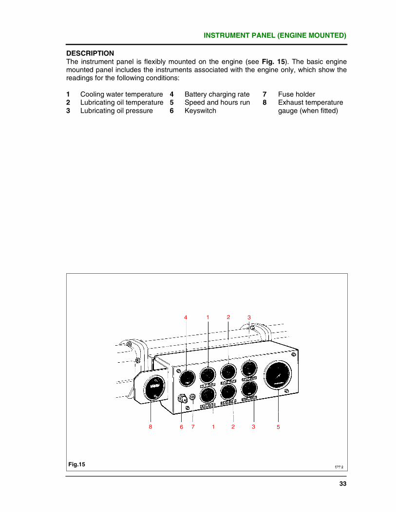
DESCRIPTIONThe instrument panel is flexibly mounted on the engine (see Fig. 15). The basic enginemounted panel includes the instruments associated with the engine only, which show thereadings for the following conditions:
1 Cooling water temperature 4 Battery charging rate 7 Fuse holder2 Lubricating oil temperature 5 Speed and hours run 8 Exhaust temperature3 Lubricating oil pressure 6 Keyswitch gauge (when fitted)
Fig.15
1 2 34
8 6 7 1 2 3 5
INSTRUMENT PANEL
34 http://www.brizmotors.ru/equipment/ctm/sp.1845/
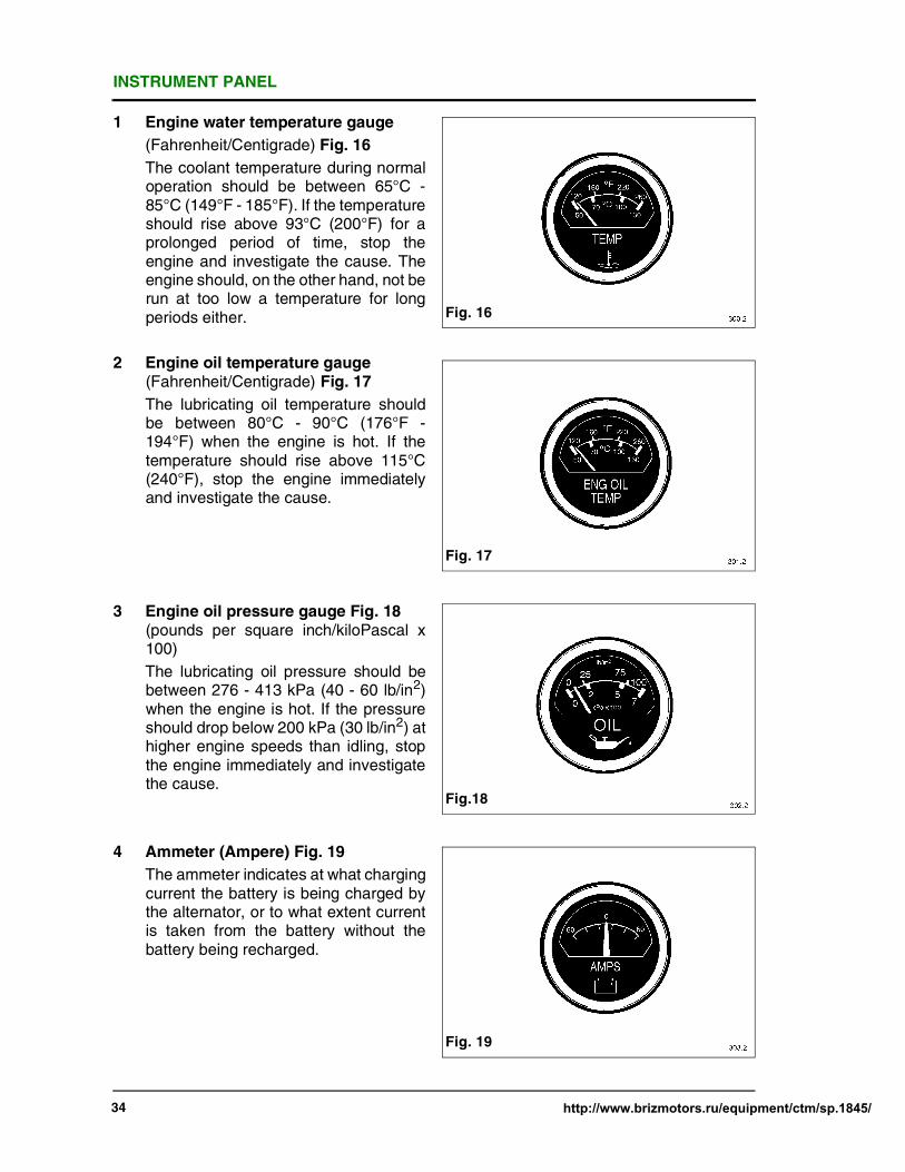
1 Engine water temperature gauge
(Fahrenheit/Centigrade) Fig. 16
The coolant temperature during normaloperation should be between 65°C -85°C (149°F - 185°F). If the temperatureshould rise above 93°C (200°F) for aprolonged period of time, stop theengine and investigate the cause. Theengine should, on the other hand, not berun at too low a temperature for longperiods either.
2 Engine oil temperature gauge(Fahrenheit/Centigrade) Fig. 17
The lubricating oil temperature shouldbe between 80°C - 90°C (176°F -194°F) when the engine is hot. If thetemperature should rise above 115°C(240°F), stop the engine immediatelyand investigate the cause.
3 Engine oil pressure gauge Fig. 18(pounds per square inch/kiloPascal x100)
The lubricating oil pressure should bebetween 276 - 413 kPa (40 - 60 lb/in2)when the engine is hot. If the pressureshould drop below 200 kPa (30 lb/in2) athigher engine speeds than idling, stopthe engine immediately and investigatethe cause.
4 Ammeter (Ampere) Fig. 19
The ammeter indicates at what chargingcurrent the battery is being charged bythe alternator, or to what extent currentis taken from the battery without thebattery being recharged.
Fig. 16
Fig. 17
Fig.18
Fig. 19

INSTRUMENT PANEL
http://www.brizmotors.ru/equipment/ctm/sp.1845/ 35
5 Engine tachometer and hour counter
(revolutions per minute x 1000 andhours) Fig. 20
The electrically operated tachometer/hour counter shows the speed of theengine in r/min. and the actual operatinghours the engine has run. Thetachometer/hour counter startsoperating from an alternator voltage of12 V onwards, which has already beenreached at engine idling speed.
6 Key switch (3 position) (Off/run/start)
The hand operated keyswitch withswitch lock is moved by a separate keyto the positions shown, (see Fig. 21)viewed from front of switch.
7 Fuse holder
To protect the instrument panel a 2 ampfuse is fitted to remove the fuse (1)unscrew its holder (2) (see Fig. 21.1).
Key
(Fig. 21)
1 Off
2 Run
3 Start
Fig. 20
Fig. 21
12
3
Fig. 21.1
12
EXHAUST TEMPERATURE GAUGE (OPTIONAL)
36 http://www.brizmotors.ru/equipment/ctm/sp.1845/
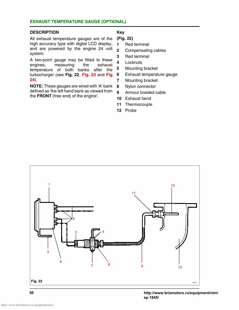
DESCRIPTION
All exhaust temperature gauges are of thehigh accuracy type with digital LCD display,and are powered by the engine 24 voltsystem.
A two-point gauge may be fitted to theseengines, measuring the exhausttemperature of both banks after theturbocharger (see Fig. 22, Fig. 23 and Fig24).
NOTE: These gauges are wired with 'A' bankdefined as 'the left hand bank as viewed fromthe FRONT (free end) of the engine'.
Key
(Fig. 22)
1 Red terminal
2 Compensating cables
3 Red terminal
4 Locknuts
5 Mounting bracket
6 Exhaust temperature gauge
7 Mounting bracket
8 Nylon connector
9 Armour braided cable
10 Exhaust bend
11 Thermocouple
12 Probe
Fig. 22
1
2
5
6
3 4
7 8
11
12
9 10
http://www.brizmotors.ru/equipment/ctm/

EXHAUST TEMPERATURE GAUGE (OPTIONAL)
http://www.brizmotors.ru/equipment/ctm/sp.1845/ 37
SPECIFICATION
Temperature range -20/+800°C
Resolution 1°C
Accuracy + 0.5% F.S.D.
Probe fitting 3/8" BSP
Terminal size to suit 4BA eyelet connector
Cable size 2 core 7 strand 0.1 mm dia.
Type of cable Compensating type K
i.e. nickel/chrome or
nickel/alumel to British
Standard 4937 alternatively
copper/constantan
Supply 24V DC or PP3 lithiumbattery
(earlier engines)
Key
(Fig. 23)
1 Push button to read (battery poweredonly)
2 Switch
(Fig. 24)
1 24V DC Supply
Fig. 23
1
2
Fig. 24
1

EXHAUST TEMPERATURE GAUGE (OPTIONAL)
38 http://www.brizmotors.ru/equipment/ctm/sp.1845/
A four point gauge may also be fitted whichmeasures the exhaust temperature of bothbanks before as well as after theturbocharger (see Fig. 25 and Fig. 26).
NOTE: These gauges are wired with 'A'bank defined as 'the left hand bank asviewed from the FRONT (free end) of theengine'.
With both the above gauges, a thermocoupleis inserted into each exhaust at the point tobe measured, and is connected via armourbraided cable to a nylon terminal connector.Type K compensating cables are used toconnect the nylon terminal connector to thegauge. (see Fig. 22).
Wiring is quite straightforward, with thepositive (red) terminal on the nylon terminalconnector, connected to its correspondingpositive (red) terminal at the back of thegauge (see Figs. 22, 24 and 26).
Key
(Fig. 26)
1 24V DC Suppy
Fig. 25
Fig. 26
1

MAINTENANCE SCHEDULE & CHECKLISTS
http://www.brizmotors.ru/equipment/ctm/sp.1845/ 39
Towards the rear of this section are twocheck sheets, one for continuous duty setsand one for standby duty sets, which are tobe used as a guide for operators andmaintenance personnel. The followingschedule details some of the maintenance tobe carried out as in the maintenance checklists. However, not all are detailed. In thesecases please refer to the WorkshopManual. The Schedule within this sectionwill be perfectly suitable for an engineworking under average conditions. If yourengine is working under particularly arduous,dirty or dusty conditions, it will be necessaryto undertake more frequent servicing,particularly in respect of the lubricating oil,fuel systems and air cleaners. Correct andregular maintenance will help prolong the lifeof your engine.
The periods referred to throughout thismaintenance section are true engine runninghours as indicated on the hour recorder fittedin the instrument panel.
DAILY INSPECTION
LUBRICATING OIL LEVEL
With the engine stopped for at least 5minutes withdraw the dipstick, wipe cleanand re-insert into the sump. After waiting 5 -10 seconds for the oil level to stabilise,withdraw and check the oil level in relation tothe two marks on the dipstick. If the level isbelow the top mark, remove the oil filler capand add the correct grade of oil to bring thelevel up to the top mark. Always replace thefiller cap immediately replenishment iscompleted.
COOLANT LEVEL
With the engine stopped, remove radiatorcap; the coolant should be 25 mm (1") belowthe top of the filler neck. If the level is low topup with a solution of water and inhibitor orwater and anti-freeze similar to that alreadyin the engine. Refer to page 21.
LEAKS
Visually check the engine for fuel, oil, coolantand exhaust leaks, repairing wherenecessary.
AIR FILTER MAINTENANCE
(See Section A4 Maintenance Manual)
The middle section of the restriction indicator'A' will remain clear while the air cleaner is ina serviceable condition. When the filterreaches its contamination limit the restrictionindicator will sense the change in manifoldpressure and middle section 'A' will changeto red. At this point the air filter must bechanged. When the air filters have beenchanged reset the indicator by pressingbutton 'B'. (See Fig. 26.1). Check this signaldaily.
WARNING MAKE QUITECERTAIN THE
ENGINE CANNOT BE STARTEDBEFORE UNDERTAKING ANYMAINTENANCE, PARTICULARLY IN THECASE OF AUTOMATICALLY STARTINGGENERATING SETS.
Fig. 26.1
A
B
WARNING THE COOLINGSYSTEM IS
PRESSURISED - DO NOT REMOVE THEFILLER CAP WHEN THE ENGINE IS HOT.HAND PROTECTION MUST BE WORN.

MAINTENANCE SCHEDULE & CHECKLISTS
40 http://www.brizmotors.ru/equipment/ctm/sp.1845/
AIR FILTER MAINTENANCE
GENERAL SERVICING INSTRUCTIONS
Servicing procedures include replacing thefilter element, cleaning the filter housing, andassuring that all piping and hoseconnections from the filter outlet to theturbocharger intake are sealed and airtight.(See Fig. 27).
Key
(Fig. 27)
1 Mesh guard
2 Element
3 End cover
4 Pre-cleaner (Cyclone unit) (Optional)
WARNING REPLACE ANYELEMENT WHICH IS
DAMAGED. NEVER EXCEEDRECOMMENDED MAXIMUM. NEVERBLOW DIRT OUT OF THE FILTERHOUSING. THIS MAY INTROSUCEDUST INTO THE ENGINE. INSTEAD,USE A CLEAN, DAMP CLOTH. DO NOTOIL THE ELEMENT. ALWAYS USE EYEPROTECTION WHEN USINGCOMPRESSED AIR.
WARNING DISCONNECTBATTERIES OR ANY
OTHER MEANS OF STARTING ENGINE.
Fig. 27
1
2
34
http://www.brizmotors.ru/equipment/ctm/

MAINTENANCE SCHEDULE & CHECKLISTS
http://www.brizmotors.ru/equipment/ctm/sp.1845/ 41
DAILY INSPECTION
DRAINING THE WATER TRAP/SEDIMENTER (WHERE FITTED)
There are no moving parts or elements toservice, however daily open the drain plug toremove collected water and sediment. Theplug is self retaining, unscrew until loose.Leave open until clean fuel is seen. Screwback in (see Fig. 28).
AFTER FIRST 50 HOURS ONLY
FENNER TAPER LOCK BUSHES
Maintenance Instructions
Experience has shown that taper lockbushes, as fitted in the fan and alternatordriven pulleys, can work loose shortly afterbeing put into service. After a bush has beenrun for the first 50 hours, check the tightnessof the screws. Tighten the screws graduallyand alternately until tightened to the requiredtorque (see Torque Settings). Replace anyguards removed before running the engine(see Fig. 29).
AFTER FIRST 100 HOURS
NEW OR REBUILT ENGINES
It is essential to carry out the followingmaintenance procedure after the initial 100hours.
Equalise bridge pieces and check valveclearances (see pages 55-58).
EVERY 250 HOURS OR EVERY 6MONTHS
ENGINE OIL AND FILTERS
Change engine oil and filter (see page 48).
Equalise bridge pieces and check valveclearances (see pages 55-58).
Key
(Fig. 29)
1 Locating screw
WARNING DISCONNECTBATTERIES OR ANY
OTHER MEANS OF STARTING. ALWAYSWEAR PROTECTIVE GLOVES.
Fig. 28
Fig. 29
http://www.brizmotors.ru/equipment/ctm/

MAINTENANCE SCHEDULE & CHECKLISTS
42 http://www.brizmotors.ru/equipment/ctm/sp.1845/
EVERY 250 HOURS OR 6 MONTHS
CENTRIFUGAL OIL FILTER (IF FITTED)
Stop the engine, and allow time for the oil todrain back to the sump. Refer to Fig. 30.
1 Slacken safety clamp (1) unscrew covernut and lift off cover.
2 Lift off rotor assembly (2) havingallowed oil to drain from nozzles. Therotor should be removed and replacedon the spindle with extreme care inorder to ensure that bearings are notdamaged.
3 Secure rotor in dismantling tool T6253/292. Unscrew rotor cover nut (3) andseparate rotor cover from body.
4 Remove standtube (4) using extractiontool T6253/293 and clean.
5 Remove sludge from inside the rotor bymeans of a spatula and wipe clean.Ensure that all rotor components arethoroughly cleaned and free fromdeposits of dirt before reassembling therotor. Failure to do so could cause anout-of-balance condition which willaccelerate bearing spindle wear.
6 Clean nozzle with brass wire. Examine'O'-ring (5) and renew if damaged.
7 Reassemble rotor completely andtighten top nut.
IMPORTANT: Ensure that rotor coverand rotor body are always matched bybalance reference number and pinlocation.
DO NOT INTERCHANGE ROTORCOVERS.
8 Examine spindle journals, if damaged orworn replace with body assemblycomplete.
9 Reassemble filter completely, checkingthat rotor revolves freely, then replacefilter body cover. Tighten cover nut andsecure safety clamp. The clamp ringshould be securely fitted at all times andthe filter should not be run without theclamp ring fitted.
10 With engine running check all joints forleakage. Check for excessive vibration.
See page 19 for oil change periods.
WARNING DISCONNECTBATTERIES OR ANY
OTHER MEANS OF STARTING.ALWAYS WEAR PROTECTIVE GLOVES.
Fig. 30
2
1
3
4
5
http://www.brizmotors.ru/equipment/ctm/

MAINTENANCE SCHEDULE & CHECKLISTS
43 http://www.brizmotors.ru/equipment/ctm/sp.1845/
EVERY 250 HOURS OR EVERY 6MONTHS
ALTERNATOR DRIVE BELT
Remove the small mesh guard around thealternator. The toothed belt used to drive thealternator relies on tooth engagement totransmit load. It does not require pre-loading,however a slight initial tension to ensure thatthe belt fits snugly round the pulleys isdesirable. Using light pressure midwaybetween the two pulleys a total deflection of1.5 mm (1/16") is satisfactory (see Fig. 31).Refit the guard.
Key
(Fig. 31)
1 Pulley guard
2 Tensioning arm
3 Drive guard
4 Pivot bracket and bolt
MAINTENANCE OF COOLANT
COOLING SYSTEM
Check the specific gravity and the pH valueof the coolant (see page 25 of theWorkshop Manual). Visually check theradiator core for debris causing airrestriction.
FAN BELTS
Fan belts should be checked for wear andcondition, particularly the following faults:
a Small cracks on 'V'-belt side and base.
Generally caused by lack of belt tensionbut excessive heat and/or chemicalfumes can also give same failure.
b 'V'-belt swelling or softening.
Caused by excessive contamination byoil, certain cutting fluids or rubbersolvent.
c Whipping during running.
Usually caused by incorrect tensioning,principally on long centre drives. If aslightly higher (or lower) tension doesnot cure the problem, there may be acritical vibration frequency in thesystem, which requires re-design or theuse of a banded belt.
WARNING DISCONNECTBATTERIES OR ANY
OTHER MEANS OF STARTING THEENGINE.
Fig. 31
1
2
3
MAINTENANCE SCHEDULE & CHECKLISTS
http://www.brizmotors.ru/equipment/ctm/sp.1845/ 44
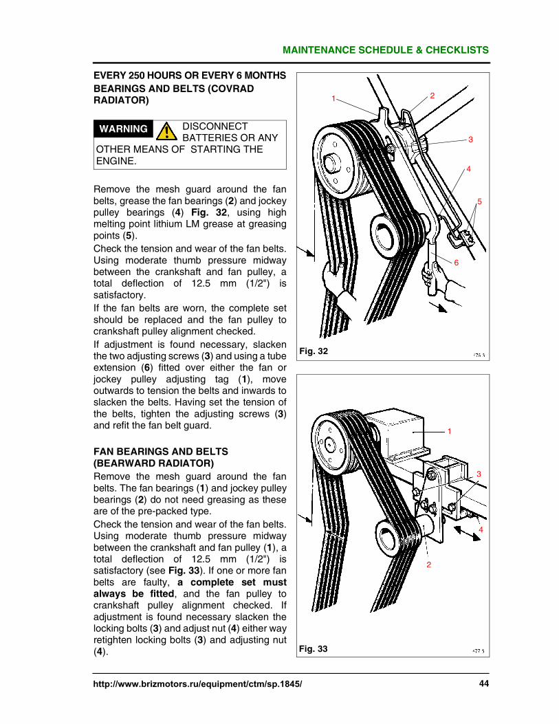
EVERY 250 HOURS OR EVERY 6 MONTHS
BEARINGS AND BELTS (COVRADRADIATOR)
Remove the mesh guard around the fanbelts, grease the fan bearings (2) and jockeypulley bearings (4) Fig. 32, using highmelting point lithium LM grease at greasingpoints (5).
Check the tension and wear of the fan belts.Using moderate thumb pressure midwaybetween the crankshaft and fan pulley, atotal deflection of 12.5 mm (1/2") issatisfactory.
If the fan belts are worn, the complete setshould be replaced and the fan pulley tocrankshaft pulley alignment checked.
If adjustment is found necessary, slackenthe two adjusting screws (3) and using a tubeextension (6) fitted over either the fan orjockey pulley adjusting tag (1), moveoutwards to tension the belts and inwards toslacken the belts. Having set the tension ofthe belts, tighten the adjusting screws (3)and refit the fan belt guard.
FAN BEARINGS AND BELTS(BEARWARD RADIATOR)
Remove the mesh guard around the fanbelts. The fan bearings (1) and jockey pulleybearings (2) do not need greasing as theseare of the pre-packed type.
Check the tension and wear of the fan belts.Using moderate thumb pressure midwaybetween the crankshaft and fan pulley (1), atotal deflection of 12.5 mm (1/2") issatisfactory (see Fig. 33). If one or more fanbelts are faulty, a complete set mustalways be fitted, and the fan pulley tocrankshaft pulley alignment checked. Ifadjustment is found necessary slacken thelocking bolts (3) and adjust nut (4) either wayretighten locking bolts (3) and adjusting nut(4).
WARNING DISCONNECTBATTERIES OR ANY
OTHER MEANS OF STARTING THEENGINE.
Fig. 32
1 2
3
4
5
6
Fig. 33
1
2
3
4

MAINTENANCE SCHEDULE & CHECKLISTS
45 http://www.brizmotors.ru/equipment/ctm/sp.1845/
EVERY 250 HOURS OR EVERY 6 MONTHS
CRANKCASE BREATHER, EARLIERENGINES (RADIATOR COOLED)
An extension pipe runs from both sides of theengine gearcase to the engine breathers,which are mounted on each side of theradiator Fig. 34 and Fig. 35. Unscrew eachbreather by turning it anti-clockwise. Wash itthoroughly. Shake it as dry as possible,finally blow it dry with compressed air andscrew the breather firmly back into position.
WARNING DISCONNECTBATTERIES OR ANY
OTHER MEANS OF STARTING. ALWAYSWEAR EYE PROTECTION ANDPROTECTIVE GLOVES WHENCLEANING BREATHER.
Fig. 34
Fig. 35
http://www.brizmotors.ru/equipment/ctm/
MAINTENANCE SCHEDULE & CHECKLISTS
http://www.brizmotors.ru/equipment/ctm/sp.1845/ 46
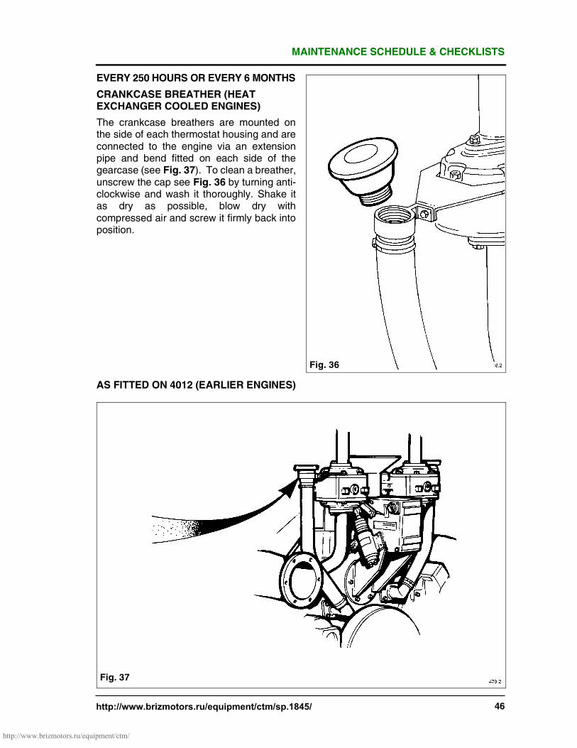
EVERY 250 HOURS OR EVERY 6 MONTHS
CRANKCASE BREATHER (HEATEXCHANGER COOLED ENGINES)
The crankcase breathers are mounted onthe side of each thermostat housing and areconnected to the engine via an extensionpipe and bend fitted on each side of thegearcase (see Fig. 37). To clean a breather,unscrew the cap see Fig. 36 by turning anti-clockwise and wash it thoroughly. Shake itas dry as possible, blow dry withcompressed air and screw it firmly back intoposition.
AS FITTED ON 4012 (EARLIER ENGINES)
Fig. 36
Fig. 37
http://www.brizmotors.ru/equipment/ctm/

MAINTENANCE SCHEDULE & CHECKLISTS
47 http://www.brizmotors.ru/equipment/ctm/sp.1845/
EARLY 250 HOURS OR 6 MONTHS
CRANKCASE BREATHER (RADIATOROR HEAT LATEST EXCHANGERCOOLED ENGINES)
The crankcase breathers are mounted onthe side of the thermostat housings and areconnected to the engine via an extensionpipe and bend fitted on each side of thegearcase (see Fig. 39). To clean thebreather remove the top cover see Fig. 38and withdraw the two wire mesh elementsand wash thoroughly. Shake as dry aspossible, finally blow dry with an air line.Refit the elements into the breather body,and fit the top cover firmly back into position.
NOTE: When replacing the cover check thesealing gasket is in good condition and thecover has located on its dowel.
AS FITTED ON ALL 4016 ENGINES AND4012 (CURRENT ENGINES)
Fig. 38
Fig. 39
http://www.brizmotors.ru/equipment/ctm/
MAINTENANCE SCHEDULE & CHECKLISTS
http://www.brizmotors.ru/equipment/ctm/sp.1845/ 48
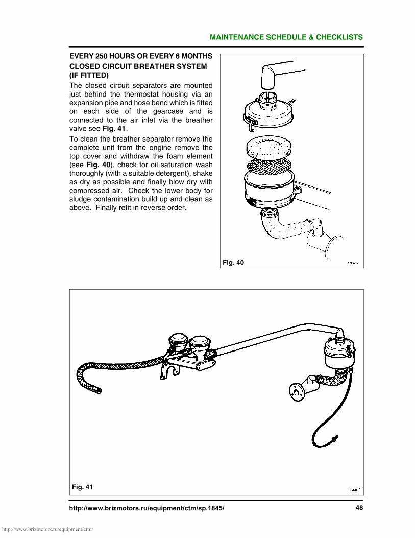
EVERY 250 HOURS OR EVERY 6 MONTHS
CLOSED CIRCUIT BREATHER SYSTEM(IF FITTED)
The closed circuit separators are mountedjust behind the thermostat housing via anexpansion pipe and hose bend which is fittedon each side of the gearcase and isconnected to the air inlet via the breathervalve see Fig. 41.
To clean the breather separator remove thecomplete unit from the engine remove thetop cover and withdraw the foam element(see Fig. 40), check for oil saturation washthoroughly (with a suitable detergent), shakeas dry as possible and finally blow dry withcompressed air. Check the lower body forsludge contamination build up and clean asabove. Finally refit in reverse order.
Fig. 40
Fig. 41
http://www.brizmotors.ru/equipment/ctm/
MAINTENANCE SCHEDULE & CHECKLISTS
49 http://www.brizmotors.ru/equipment/ctm/sp.1845/
EVERY 250 HOURS OR EVERY 6 MONTHS
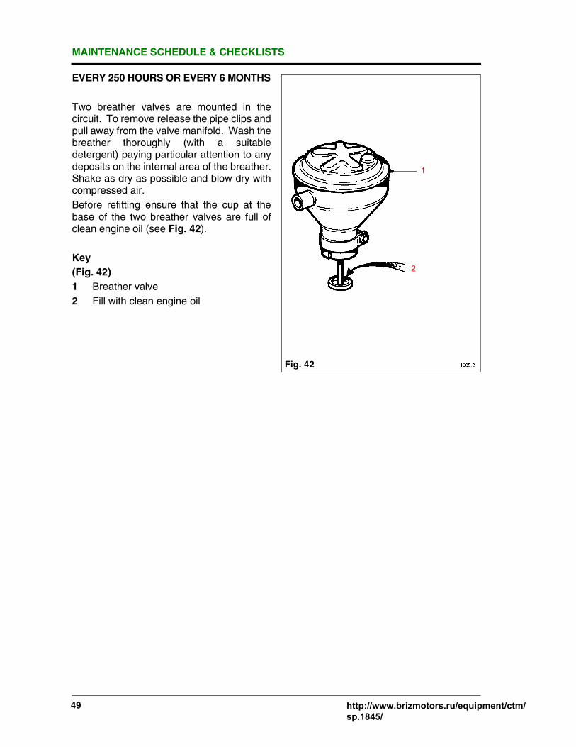
Two breather valves are mounted in thecircuit. To remove release the pipe clips andpull away from the valve manifold. Wash thebreather thoroughly (with a suitabledetergent) paying particular attention to anydeposits on the internal area of the breather.Shake as dry as possible and blow dry withcompressed air.
Before refitting ensure that the cup at thebase of the two breather valves are full ofclean engine oil (see Fig. 42).
Key
(Fig. 42)
1 Breather valve
2 Fill with clean engine oil
Fig. 42
1
2

MAINTENANCE SCHEDULE & CHECKLISTS
http://www.brizmotors.ru/equipment/ctm/sp.1845/ 50
EVERY 250 HOURSOR EVERY 6 MONTHS
CHANGINGENGINEOILANDOILFILTERS(STANDARD HORIZONTAL TYPE)
With the engine stopped, place a suitablecontainer of at least 214 litres (47 gal)beneath the drain plug (which is situated onthe bottom edge of the sump directly underthe dipstick). Remove the drain plug andallow the oil to drain. This operation is bestcarried out while the engine is still warm asthe thinner oil will drain more quickly. Whilethe oil is draining remove all three oil filtersper bank, two on the main header supplyingthe bearings and one on the single headersupplying the piston jets, by turning themanti-clockwise with a strap wrench Fig. 43).
NOTE: Removal of the oil filters will allowan escape of oil from the filter headers. It istherefore recommended that a suitablecontainer of at least 5 litres (1 gal) capacity ispositioned under each header prior to filterremoval as the oil filters are of the disposablecanister type they must be thrown away. Fillthe oil filters with clean engine oil prior tofitting. Wipe clean the sealing faces andthreaded bosses of the header. Smearengine oil on the captive rubber sealing ringand carefully screw each new filter up to theoil header using firm hand pressure only.
Having drained the engine oil, refit the drainplug and fill the engine with the appropriategrade of new oil (see pages 19 & 20 ) .Ensure that the switch on the control paneland fuel stop lever on the engine are both intheir respective 'stop' positions, and that theair shut-off valves have been manually set tothe 'run' position (see Fig. 2). Then motorthe engine over on the starter until apressure of approximately 40 kPa (5lb/in2) isindicated on the pressure gauge, thusensuring that the oil filters are full and theturbocharger bearings are primed (see page23). Check the dipstick and add more oil ifnecessary.
CHANGING THE OPTIONAL CHANGE-OVER LUBRICATING OIL FILTERS
These special duplex filters are normallyintended for use on long running engines, orwhere a servicing requirement may occurwhen it is impossible to stop the engine tochange the filters. For this reason they arefitted with a three way change over valve inthe head, which enables the elements to bechanged, one at a time whilst the enginecontinues to run. They are normally mountedon the engine, but they may also be remotelymounted and connected to the engine bymeans of flexible pipes.
NOTE: If the flexible connections to the filterare removed for any reason, it is essentialthat they are reconnected correctly to avoidunfiltered oil getting into the engine. See Fig.44. Failure to change filters when due canalso lead to trouble from unfiltered oil.
Always fill a replacement filter with cleanengine oil before fitting.
WARNING DISCONNECTBATTERIES OR ANY
OTHER MEANS OF STARTING. WEARPROTECTIVE GLOVES.
Fig. 43
WARNING IT IS ESSENTIAL TOPRIME THE SYSTEM
AFTER AN OIL AND FILTER CHANGE TOAVOID OIL STARVATION PROBLEMS,WITH AUTOMATICALLY STARTINGGENERATOR SETS, WHICH TAKE FULLLOAD IMMEDIATELY AFTER STARTING.
http://www.brizmotors.ru/equipment/ctm/

MAINTENANCE SCHEDULE & CHECKLISTS
51 http://www.brizmotors.ru/equipment/ctm/sp.1845/
EVERY 250 HOURS OR 6 MONTHS
CHANGING THE FILTER ELEMENTSWHEN THE ENGINE IS STOPPED
All that is necessary is to unscrew thecanisters with a strap wrench as shown inFig. 44, without moving the change-overvalve, as there is no pressure in the systemwhen the engine is stationary. The undersideof the header is then wiped clean, and asmear of clean oil applied to the sealing ringson the new canisters, before screwing themup by hand and tightening them by no morethan three quarters of a turn after the sealscontact the header. Check for leaks after theengine is restarted.
Key
(Fig. 44)
1 Change right filter
2 Normal running
3 Change left filter
Early Engines (optional)
Fig. 44
1 2 3
http://www.brizmotors.ru/equipment/ctm/

MAINTENANCE SCHEDULE & CHECKLISTS
http://www.brizmotors.ru/equipment/ctm/sp.1845/ 52
EVERY 250 HOURS OR 6 MONTHS
CHANGING THE CHANGE OVER FILTERELEMENTS WITHOUT STOPPING THEENGINE
If the filters must be changed withoutstopping the engine. The normal position ofthe change-over valve is with the leg of the'T' mark pointing upwards, see Fig. 44 or 45,when both filter elements are in circuit.Turning the valve so that the leg of the 'T'points to the left puts the right hand filter outof service, so that it may be exchanged for anew one which should be filled with new oilbefore screwing the canister into positionusing firm hand pressure only. Turning thevalve so that the leg of the 'T' points to theright puts the left hand filter out of service, sothat this one can now be exchanged for anew canister also primed with oil as before.The valve is then returned to its originalposition, so that both elements of the filterare back in service. Check for leaks beforeleaving the engine and increasing its speed.
Later Engines (Optional)
NOTE: Prepare for some spillage of oil aseach canister is removed, by placing a bowlof about 5 litres or 1 gallon capacity underthe filters.
NOTE: If the pipes connecting the change-over oil filters to the engine are removed forany reason, it is essential that they bereconnected correctly to avoid unfiltered oilgetting into the system. See Fig. 44 or 45.
Left hand side pipe (A) fitted to the oil coolerheader fits to the front of the oil filter header.
Right hand side pipe (B) fitted to the oilcooler header fits to the rear of the filterheader.
Key
(Fig. 45)
1 Change right filter
2 Normal running
3 Change left filter
Fig. 45
A B
1 2 3

MAINTENANCE SCHEDULE & CHECKLISTS
53 http://www.brizmotors.ru/equipment/ctm/sp.1845/
EVERY 250 HOURSOR EVERY 6MONTHS
CHANGING FUEL FILTER ELEMENTS
NOTE: Ensure complete cleanliness isadhered to.
HORIZONTAL FUEL FILTER (EARLYENGINES)
First turn off the fuel on installations having anoverhead supply, drain the sediment trap orpre-fuel filter (if fitted) before filter removal.
Remove the two fuel filters (one filter on eachbank) located at the opposite end of theengine to the flywheel, by turning them anti-clockwise with a strap wrench Fig. 46.
NOTE: Removal of the filters will allow anescape of fuel from the filter housings andpipes, it is therefore recommended that asuitable container of at least 5 litres (1 gal)capacity is positioned under each housingprior to filter removal.
As the fuel filters are of the non-serviceablecanister type they must be thrown away.Wipe clean the sealing faces and threadedbosses of the housings. Smear clean engineoil on the captive rubber sealing ring andcarefully screw the new canister up to thehousing using firm hand pressure only.
Turn on the fuel supply (if applicable) andvent the fuel system (refer to pages 25-26).
the filters for leaks with the engine running.
Key
(Fig. 46)
1 Oil filters
FUEL FILTER AND WATER SEPARATOR(FITTED TO 4012 ENGINES ONLY)
First turn off the fuel supply, drain thesediment trap or pre-fuel filter (if fitted)before filter renewal. Remove the fuel filtercanister, which is located on the side of thegearcase, by unscrewing from the filterheader with a strap wrench (Fig. 47).
STRAINER (FITTED TO 4016 ENGINESONLY)
The screen inside the strainer body shouldbe removed for cleaning (using a suitablecleaning agent) at the same time that thefilter elements are replaced. To remove thescreen, unscrew the cap nut under the bodyand withdraw it, catching any spillage of fuelin a 5 litre (1 gal) container.
WARNING DISCONNECTBATTERIES OR
OTHER MEANS OF STARTING. ALWAYSWEAR PROTECTIVE GLOVES
Fig. 46
1
Fig. 47

MAINTENANCE SCHEDULE & CHECKLISTS
http://www.brizmotors.ru/equipment/ctm/sp.1845/ 54
EVERY 250 HOURSOR EVERY 6 MONTHS
CHANGING THE CHANGE OVER FUELFILTER ELEMENTS WHEN THE ENGINEIS STOPPED
All that is necessary is to unscrew thecanisters with a strap wrench as shown inFig. 48, leaving the change-over lever in thevertical position as there is no pressure in thefuel system with the engine stationary. Thereplacement canisters are screwed on byhand, after applying a smear of clean engineoil to the rubber seals, and tightening by firmhand pressure only. Bleed the air from thenew filters by slackening the vent screwsand operating the priming pump. Check forleaks when the engine is restarted.
CHANGING THE CHANGE OVER FUELFILTER ELEMENTS WHEN THE ENGINEIS RUNNING
The normal position of the change-overvalve lever is vertically upwards, when bothfilters are in circuit. Turning the lever to theleft, puts the right hand filter out of service,so that the right hand canister may beexchanged for a new one, smearing the sealwith clean engine oil and tightening by firmhand pressure only. Bleed the air from thenew filter by means of the vent screw as thelever is returned to the vertical position.Turning the lever so that it points the right,puts the left hand filter out of service so thatit can then be exchanged for a new one, asbefore. Again bleed the air from the new filteras the lever is returned to its normal verticalposition, so that both elements are back incircuit, and check for leaks before leavingthe engine.
NOTE: Prepare for some spillage of fuel byplacing a bowl of about 5 litres or 1 galloncapacity under the filter when changing thecapacities.
CLEANING WATER TRAP/SEDIMENTER(WHERE FITTED)
Open drain plug (1) to remove collectedwater and sediment. The plug is selfretaining, leave open until clean fuel is seenthen screw back in see page 41. Removethe bowl by unscrewing three screws (2).Clean thoroughly all components and drywith compressed air. Replace joint washer ifdamaged.
FUEL SUPPLY AND PRIMING CIRCUITSMAINTENANCE INSTRUCTIONS
FUEL LIFT PUMP
For information on the lift pump see SectionKK1 of the Workshop Manual.
HAND PRIMING PUMP (OPTIONAL)
The pump requires no maintenance butshould it fail to operate a replacement unit isrequired.
WARNING DISCONNECTBATTERIES OR ANY
OTHER MEANS OF STARTING.ALWAYS WEAR PROTECTIVE GLOVES.
Fig. 48
1
Fig. 48.1
2
1
MAINTENANCE SCHEDULE & CHECKLISTS
55 http://www.brizmotors.ru/equipment/ctm/sp.1845/
EVERY 250 HOURS OR 6 MONTHS
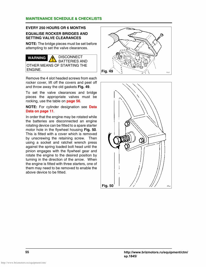
EQUALISE ROCKER BRIDGES ANDSETTING VALVE CLEARANCES
NOTE: The bridge pieces must be set beforeattempting to set the valve clearances.
Remove the 4 slot headed screws from eachrocker cover, lift off the covers and peel offand throw away the old gaskets Fig. 49.
To set the valve clearances and bridgepieces the appropriate valves must berocking, use the table on page 56.
NOTE: For cylinder designation see DataData on page 11.
In order that the engine may be rotated whilethe batteries are disconnected an enginerotating device can be fitted to a spare startermotor hole in the flywheel housing Fig. 50.This is fitted with a cover which is removedby unscrewing the retaining screw. Thenusing a socket and ratchet wrench pressagainst the spring loaded bolt head until thepinion engages with the flywheel gear androtate the engine to the desired position byturning in the direction of the arrow. Whenthe engine is fitted with three starters, one ofthem may need to be removed to enable theabove device to be fitted.
WARNING DISCONNECTBATTERIES AND
OTHER MEANS OF STARTING THEENGINE. Fig. 49
Fig. 50
http://www.brizmotors.ru/equipment/ctm/

MAINTENANCE SCHEDULE & CHECKLISTS
http://www.brizmotors.ru/equipment/ctm/sp.1845/ 56
Engine 4012T.D.C.
Valves Rocking onCylinder No.
Set Bridge Piecesand Valve Clearances
on Cylinder no.
A1 & A6 A6 A1
B1 & B6 B1 B6
A2 & A5 A2 A5
B2 & B5 B5 B2
A3 & A4 A4 A3
B3 & B4 B3 B4
A1 & A6 A1 A6
B1 & B6 B6 B1
A2 & A5 A5 A2
B2 & B5 B2 B5
A3 & A4 A3 A4
B3 & B4 B4 B3
Engine 4016T.D.C.
Valves Rocking onCylinder No.
Set Bridge Piecesand Valve Clearances
on Cylinder no.
A1 & A8 A8 A1
B1 & B8 B8 B1
A3 & A6 A6 A3
B3 & B6 B6 B3
A7 & A2 A2 A7
B7 & B2 B2 B7
A5 & A4 A4 A5
B5 & B4 B4 B5
A1 & A8 A1 A8
B1 & B8 B1 B8
A3 & A6 A3 A6
B3 & B6 B3 B6
A7 & A2 A7 A2
B7 & B2 B7 B2
A5 & A4 A5 A4
B5 & B4 B5 B4

MAINTENANCE SCHEDULE & CHECKLISTS
57 http://www.brizmotors.ru/equipment/ctm/sp.1845/
EVERY 250 HOURSOR EVERY 6MONTHS
If the valves required to be rocking areclosed, rotate the engine one revolution,which will bring these valves to the rockingposition.
The flywheel housing has an inspection holedirectly below the 'B' bank turbocharger(s)through which the flywheel markings may beseen to line up with the pointer set in theflywheel housing Fig. 51.
The flywheel is marked as follows:-
4012 4016T.D.C. A1-A6 T.D.C. A1-A8
A5-A2 A3-A6A3-A4 A7-A2B1-B6 A5-A4B5-B2 B1-B8B3-B4 B3-B6
B7-B2B5-B4
EQUALISING THE BRIDGE PIECES
Having rotated the engine to the correctposition see the table on page 56, check thatthe inlet and exhaust rockers to be adjustedhave clearance before continuing with thenext operation. Loosen the locknut on eachbridge piece adjuster, screw the adjuster outuntil the fixed side of the bridge piece restson its valve, hold the top edge of the bridgepiece down with one hand Fig. 52, thenscrew the adjuster down until you feel ittouch the valve, thereby equalising valve lift.Tighten the lock nut without moving theadjuster.
WARNING DISCONNECT
BATTERIES AND ALL
OTHER MEANS OF STARTING THE
ENGINE.
Fig. 51

MAINTENANCE SCHEDULE & CHECKLISTS
http://www.brizmotors.ru/equipment/ctm/sp.1845/ 58
EVERY 250 HOURSOR EVERY 6 MONTHS
E.g. to adjust valves and bridge pieces onNo. A1 cylinder set No. A6 cylinder valvesrocking for the 4012 engine and No. A8 forthe 4016 engine.
RESETTING THE VALVE CLEARANCESWITH ENGINE COLD
With both bridge pieces equalised, checkand adjust the valve clearance using a 0.4mm (0.016") feeler gauge for both theexhaust and inlet valve set between eachrocker and bridge piece Fig. 53. If requiredscrew the adjuster until the rocker is bearinglightly on the feeler gauge. Tighten the locknut without moving the adjuster. (SeeTorque Settings page 16). The feelergauge should be a slide fit between therocker and bridge piece, thereby giving thecorrect clearance. Refit the rocker coverwith a new gasket.
For further instructions on maintenanceplease refer to the Maintenance Section ofthe Workshop Manual.
LINKAGE FROM THE GOVERNOR TOTHE CONTROL SHAFTS
Check the freedom of operation of theseimportant linkages, which are vital to theproper running of the engine.
WARNING FAILURE TO
EQUALISE A BRIDGE
PIECE MAY RESULT IN ENGINE
DAMAGE. ALWAYS CHECK THAT THE
PARTS FIT TOGETHER AND MOVE
FREELY, BEFORE ASSEMBLY.
WARNING DISCONNECT THE
BATTERIES AND ALL
OTHER MEANS OF STARTING ENGINE.
Fig. 52
Fig. 53

MAINTENANCE SCHEDULE & CHECKLISTS
59 http://www.brizmotors.ru/equipment/ctm/sp.1845/
OVERHAUL PERIODS
The intervals at which routine overhauls arerequired, to keep an engine in goodoperating condition, will vary considerablydepending upon operating conditions, thequality of lubricating oil and fuels used, andthe engine operating speed.
The frequency required for top overhaul willdepend upon the condition of valve seats,and in the case of prolonged light loadoperation, the amount of carbonaccumulated around the valves and on thepiston crowns.
A major influence on valve condition istappet clearance and the importance ofchecking tappet clearances every 250 hourscannot be overstressed.
After the FIRST 2500 HOURS operation of anew engine it is good practice to remove theunit injectors and check their condition, carryout a compression test, and an endoscopic(borescope) examination of liner and valvecondition. If there are any problems, thenremove TWO cylinder heads to assess thecondition of the valves, cylinder bores andfuel injectors.
If all components are in good condition,clean the parts and reassemble the engineleaving the other cylinders alone.
This inspection will enable maintenanceengineers to decide upon the requiredfrequency of top overhaul to suit theparticular application.
EVERY 2500 HOURS (TOP OVERHAUL IFNECESSARY)
A top overhaul may involve some or all of thefollowing operations depending upon thehours run, the engine application and theduty cycle.
CYLINDER HEAD
NOTE: Service exchange cylinder headsare available.
Remove the cylinder heads from the engineand remove the inlet and exhaust valves.Soak the cylinder head in a carbon removingfluid or remove all deposits by use of ascraper and wire brush.
Check for cracks especially between valveports and the injector hole. Check core plugsand replace if leaking or corroded.
When handling, always protect the bottommachined face from accidental damage.
Examine the injector tubes for leaks. Checkthe nozzle seating face.
Prior o refitting the valves, wash the headthoroughly and blow off with compressed air.If new core plugs or injector tubes have beenfitted a hydraulic pressure test to 6.9 bar(100 lb/in²) for leaks should be carried outusing hot water at 70-90°C (158-194°F) .
VALVE GUIDES
Inspect the bores of the guides for wear andcheck the fit of a new valve. Check for pick-up or scoring. Replace if necessary.
VALVES
Remove carbon and scale by soaking in awater based solvent or by use of a scraperand wire brush. Polish with fine emery cloth.Examine the valve heads for cracks. Inspectvalve seats and true up by grinding to thecorrect angle if required. Check the valvestem tip for wear and reface by grinding ifnecessary. (To a maximum limit of 0.4 mm(0.015").
Check the valve stems for wear or scoring.
Check valve heads for distortion by rollingthe stems on a surface table. Scrap any bentvalves. Replace any worn collets and valvespring retainers. Check valve protrusionafter refitting into head.
WARNING DISCONNECT THE
BATTERIES AND ALL
OTHER MEANS OF STARTING ENGINE.
WARNING WHEN USING
COMPRESSED AIR
ALWAYS WEAR EYE PROTECTION.

MAINTENANCE SCHEDULE & CHECKLISTS
http://www.brizmotors.ru/equipment/ctm/sp.1845/ 60
EVERY 2500 HOURS OR 12 MONTHS IFNECESSARY
VALVE SEAT INSERTS
Examine the valve seats for pitting and wear.If necessary reface them using a planetarygrinder and then hand lap the valves intotheir seats using grinding paste. In cases ofextreme wear or burning, fit new inserts,(see Section R4 in the Workshop Manual).
VALVE SPRINGS
Measure the free length. Compare with anew spring (See page 41 in WorkshopManual Schedule of Wear and RenewalLimits). Reject any spring which may havea permanent set.
Check the ends of the springs forsquareness.
ROCKERS AND ROCKER BRIDGES
Inspect the bridge pieces and their guidealso each rocker on its shaft for wear andreplace where necessary.
INJECTOR TUBES
These do not require replacing unless theyare leaking.
PISTONS AND LINERS
Using a blunt scraper, remove excessivecarbon from the piston crown and the linerflange face. Do not use emery cloth. Do notallow any carbon to find its way downbetween the piston and liner. Rotate theengine as required. Wipe the bores clean andlubricate before refitting the cylinder heads.
EVERY 2500 HOURS OR 12 MONTHS
COOLING SYSTEM
Drain off the coolant in the fresh watersystem using the drain plug fitted in the oilcooler end covers. Refill the system asdescribed on page 27.
GENERAL ATTENTION
Also carry out all checks and fit replacementparts as listed for each service period in theMaintenance Schedule.
EVERY 12 MONTHS CHANGE THEWOODWARD GOVERNOR OIL
Remove the drain plug from the front of thegovernor whilst the engine is still warm andcollect the 1/2 gallon / 2 litres of oil in asuitable container. Refit the plug and refillwith a similar quantity of diesel fuel.Reconnect the batteries, start the engineand run it at a low speed. Cycle the governorby opening the needle valve by two or threeturns. Let the governor hunt for a minute ortwo, then stop the engine and drain thegovernor. Repeat this flushing operationand then replace the diesel fuel with newSAE30 or SAE15W/40 engine oil.
Restart the engine and reset thecompensation adjustment and needle valvesetting. (See Sections AA54-AA75 in theWorkshop Manual for UG10 and 3161governors).
FIRST MAJOR OVERHAUL
If service schedules are adhered to majoroverhauls may not be required until 20,000hours of operation have been completed.
The charge air cooler and heat exchangerwill also need to be inspected at 10,000hours for internal cleaning of the inside andoutside of the tubes, and the maintenanceperiod determined for future overhauls.
The FIRST assessment of engine conditionwill enable maintenance engineers to planthe time of major overhauls i.e. 10,000 and20,000 hours to be carried out at convenienttimes e.g. to coincide with annual refits orfactory shut-downs.
The oil change intervals may be alteredaccording to operating experience over 1000hours by agreement with Perkins Engines(Stafford) Limited and subject to oil analysesbeing carried out on a regular basis, seepages 19 & 20 .
WARNING DISCONNECTBATTERIES AND ALL
OTHER MEANS OF STARTING.ALWAYS WEAR PROTECTIVE GLOVESAND GOGGLES.
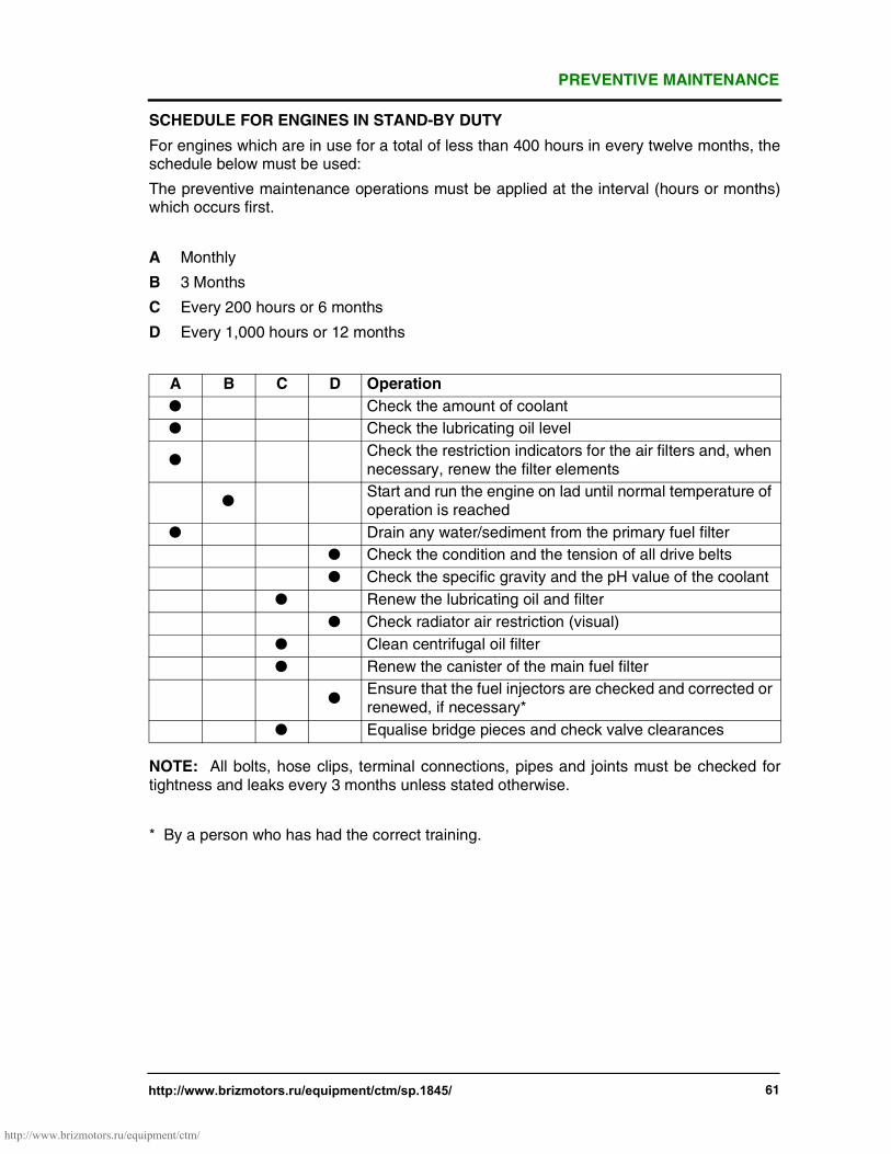
PREVENTIVE MAINTENANCE
http://www.brizmotors.ru/equipment/ctm/sp.1845/ 61
SCHEDULE FOR ENGINES IN STAND-BY DUTY
For engines which are in use for a total of less than 400 hours in every twelve months, theschedule below must be used:
The preventive maintenance operations must be applied at the interval (hours or months)which occurs first.
A Monthly
B 3 Months
C Every 200 hours or 6 months
D Every 1,000 hours or 12 months
NOTE: All bolts, hose clips, terminal connections, pipes and joints must be checked fortightness and leaks every 3 months unless stated otherwise.
* By a person who has had the correct training.
A B C D Operation
● Check the amount of coolant
● Check the lubricating oil level
●Check the restriction indicators for the air filters and, whennecessary, renew the filter elements
●Start and run the engine on lad until normal temperature ofoperation is reached
● Drain any water/sediment from the primary fuel filter
● Check the condition and the tension of all drive belts
● Check the specific gravity and the pH value of the coolant
● Renew the lubricating oil and filter
● Check radiator air restriction (visual)
● Clean centrifugal oil filter
● Renew the canister of the main fuel filter
●Ensure that the fuel injectors are checked and corrected orrenewed, if necessary*
● Equalise bridge pieces and check valve clearances
http://www.brizmotors.ru/equipment/ctm/

PREVENTIVE MAINTENANCE
62 http://www.brizmotors.ru/equipment/ctm/sp.1845/
SCHEDULE FOR ENGINES IN CONTINUOUS DUTY
For preventive maintenance operations must be applied at the interval (hours or months)which occurs first.
A Daily
B Every 250 hours or 6 months
C Every 2500 hours or 12 months
* By a person who has had the correct training.
A B C Operation
● Check the coolant level
● Check the lubricating oil level
●Check the restriction indicators for the air filters and, whennecessary, renew the filter elements
● Drain any water/sediment from the primary fuel filter
● Check the condition and the tension of all drive belts
● Check the specific gravity and the pH value of the coolant
● Renew the lubricating oil and filter
● Visually check for radiator air restriction
● Clean centrifugal oil filter
● Renew the canister of the main fuel filter
● Clean the water trap sedimenter
● Equalise bridge pieces and check valve clearances
●Check that the air charge cooler and the radiator are clean and freefrom debris
● Drain and flush the coolant system and renew coolant mixture
●Ensure that the fuel injectors are checked and corrected orrenewed, if necessary*
http://www.brizmotors.ru/equipment/ctm/

4012/4016 ENGINE FAULT TRACING
http://www.brizmotors.ru/equipment/ctm/sp.1845/ 63
Fig. 54
http://www.brizmotors.ru/equipment/ctm/
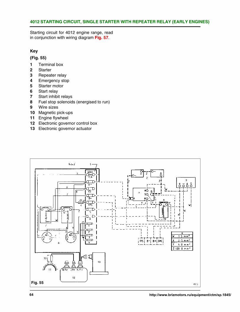
4012 STARTING CIRCUIT, SINGLE STARTERWITH REPEATER RELAY (EARLY ENGINES)
64 http://www.brizmotors.ru/equipment/ctm/sp.1845/
Starting circuit for 4012 engine range, readin conjunction with wiring diagram Fig. 57.
Key
(Fig. 55)
1 Terminal box
2 Starter
3 Repeater relay
4 Emergency stop
5 Starter motor
6 Start relay
7 Start inhibit relays
8 Fuel stop solenoids (energised to run)
9 Wire sizes
10 Magnetic pick-ups
11 Engine flywheel
12 Electronic governor control box
13 Electronic governor actuator
Fig. 55

4012/16 STARTING CIRCUIT, STARTERS AND TWIN START RELAYS(EARLY ENGINES)
http://www.brizmotors.ru/equipment/ctm/sp.1845/ 65
Starting circuit for 4012 engine range, readin conjunction with wiring diagram Fig. 57.
Key
(Fig. 56)
1 Terminal box
2 Starter motor 1
3 Starter motor 2
4 24 v Starting batteries
5 Emergency stop switch
6 Start relays
7 Start inhibit relays
8 Fuel stop solenoids (energised to run)
9 Wire sizes
10 Magnetic pick-ups
11 Engine flywheel
12 Electronic governor control box
13 Electronic governor actuator
Fig. 56

4012/16 WIRING DIAGRAM, STARTER, ELECTRONIC GOVERNOR (EARLY ENGINES)
66 http://www.brizmotors.ru/equipment/ctm/sp.1845/
NOTES:1 To enable to run immediately on
depressing start button 'FPS' must befed 24 volt +ve. To stop break this +vesupply, on overspeed stopping energiseair shutoff valves also.
2 All switches shown engine at rest.(Close on a fault).
3 Start inhibit relays allow fuel stopsolenoids to energise before cranking.
Key (Fig. 57)1 Wiring by Perkins2 Start batteries3 Repeater relay4 Engine instrument panel5 Senders6 Oil temperature7 Oil pressure8 Water temperature9 Oil temperature10 Oil pressure11 Water temperature12 Tachometer13 Ammeter14 Starter motor15 Starter relay
16 Emergency stop switch17 Wire sizes18 Oil pressure switch19 Charging alternator20 Starter inhibit relays21 Air shutoff solenoid valves energised to
stop, on overspeed fault only. Notcontinuously rated. Must be manually reset.
22 Fuel stop solenoids energised to run23 Two switch speed unit24 Switch 2 overspeed25 Switch 1 speed 600 rpm26 Micro switches27 Engine fault switches left/right/banks28AWater temp. right28BWater temp. left29AOil pressure right29BOil pressure left30 Magnetic pick-ups31 Engine flywheel32 Electronic governor control unit33 Electronic governor actuator34 Speed trim pot35 If speed trim pot is not required remove
and connect thus36 Typical terminal block
Fig. 57
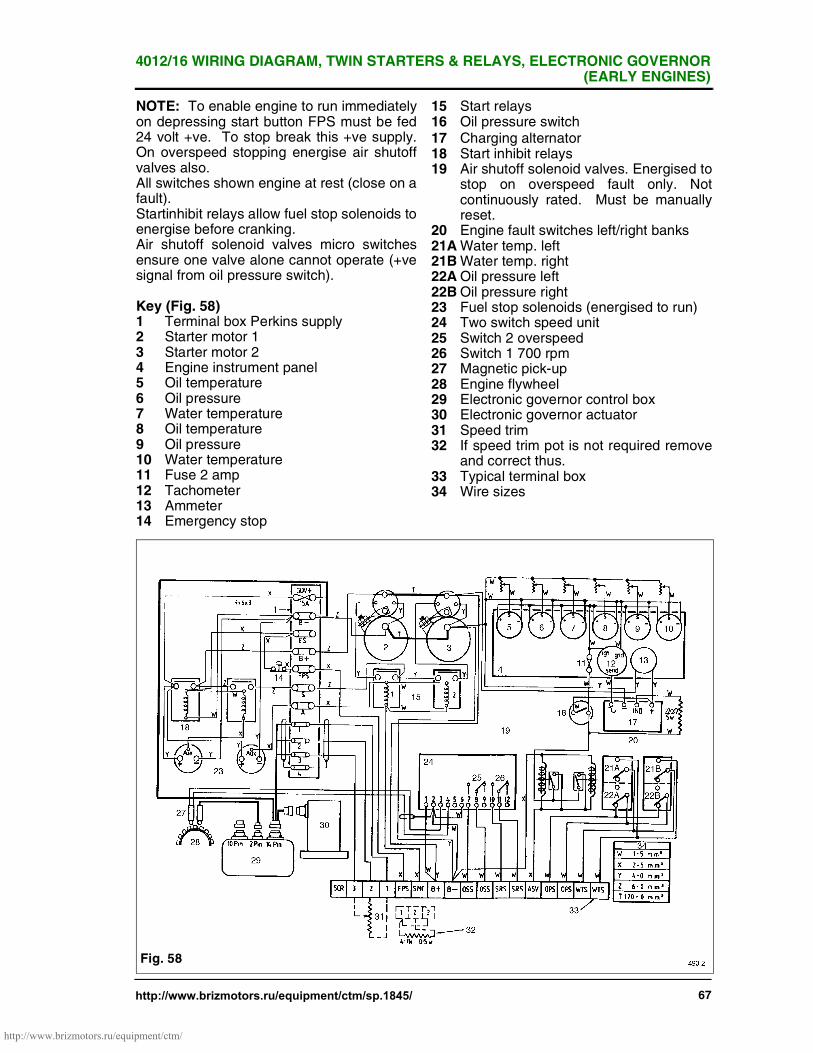
4012/16 WIRING DIAGRAM, TWIN STARTERS & RELAYS, ELECTRONIC GOVERNOR(EARLY ENGINES)
http://www.brizmotors.ru/equipment/ctm/sp.1845/ 67
NOTE: To enable engine to run immediatelyon depressing start button FPS must be fed24 volt +ve. To stop break this +ve supply.On overspeed stopping energise air shutoffvalves also.All switches shown engine at rest (close on afault).Startinhibit relays allow fuel stop solenoids toenergise before cranking.Air shutoff solenoid valves micro switchesensure one valve alone cannot operate (+vesignal from oil pressure switch).
Key (Fig. 58)1 Terminal box Perkins supply2 Starter motor 13 Starter motor 24 Engine instrument panel5 Oil temperature6 Oil pressure7 Water temperature8 Oil temperature9 Oil pressure10 Water temperature11 Fuse 2 amp12 Tachometer13 Ammeter14 Emergency stop
15 Start relays16 Oil pressure switch17 Charging alternator18 Start inhibit relays19 Air shutoff solenoid valves. Energised to
stop on overspeed fault only. Notcontinuously rated. Must be manuallyreset.
20 Engine fault switches left/right banks21AWater temp. left21BWater temp. right22AOil pressure left22BOil pressure right23 Fuel stop solenoids (energised to run)24 Two switch speed unit25 Switch 2 overspeed26 Switch 1 700 rpm27 Magnetic pick-up28 Engine flywheel29 Electronic governor control box30 Electronic governor actuator31 Speed trim32 If speed trim pot is not required remove
and correct thus.33 Typical terminal box34 Wire sizes
Fig. 58
http://www.brizmotors.ru/equipment/ctm/

4012/16 WIRING DIAGRAM, SINGLE STARTER AND HYDRAULIC GOVERNOR(EARLY ENGINES)
68 http://www.brizmotors.ru/equipment/ctm/sp.1845/
Engine fitted with regulators Europahydraulic governor
NOTE: All switches shown engine at restKey(Fig. 59)1 Engine instrument panel2 Oil temperature gauge3 Oil pressure gauge4 Water temperature gauge5 Oil temperature gauge6 Oil pressure gauge7 Water temperature8 2 Amp fuse9 Tachometer10 Ammeter11 24 volt start batteries12 Charging alternator13 Resistor14 Oil pressure switch15 Repeater relay16 Starter motor17 Starter relay
18 Solenoid19 Engine fault switches left/right bank20AWater temperature20BWater temperature21AOil pressure21BOil pressure22 Two switch speed unit23 Switch 1 700 rpm24 Switch 2 1725 rpm25 Engine flywheel26 Air shutoff solenoid valves. Energised
to stop on overspeed fault only. Notcontinuously rated. Must be manuallyreset.
27 Governor speeder motor28 Connections in main alternator for
remote volts trimmer29 Fitted terminal box30 Customers 16 core 2.5mm2 to control
panel
Fig. 59
http://www.brizmotors.ru/equipment/ctm/

4012/16 WIRING DIAGRAM, TWIN STARTERS, SINGLE START RELAY, ORIGINAL AIRSHUT OFF VALVES
http://www.brizmotors.ru/equipment/ctm/sp.1845/ 69
Key(Fig. 60)1 Terminal box2 Starter motor 13 Starter motor 24 Engine instrument panel5 Oil temperature gauge6 Oil pressure gauge7 Water temperature gauge8 Oil temperature gauge9 Oil pressure gauge10 Water temperature gauge11 Tachometer12 Ammeter13 Emergency start14 Start relay15 Oil pressure switch16 Battery charging alternator17 Start inhibit relays18 Fuel stop solenoids (energised to run)19 Air shutoff solenoid valves. Energised
to stop on overspeed fault only. Notcontinuously rated. Must be manuallyreset.
20 Two switch speed unit
21 Switch 2 overspeed22 Switch 1 speed 700 rpm23 Micro switches24 Engine fault switches left/right bank25AWater temperature switch25BWater temperature switch26AOil pressure switch26BOil pressure switch27 Engine flywheel28 Magnetic pick-ups29 Heinzmann Control box30 Heinzmann actuator31 Fitted terminal box
Fig. 60
http://www.brizmotors.ru/equipment/ctm/

4012/16 WIRING DIAGRAM, TWIN STARTERS, SINGLE START RELAY, ELECTRONICGOVERNOR (LATER ENGINES)
70 http://www.brizmotors.ru/equipment/ctm/sp.1845/
Engine engine wiring to engine fittedterminal box on diesel engines.
Key(Fig. 61)1 Engine fitted terminal box2 Starter motor 13 Starter motor 24 Emergency stop5 Start inhibit relays6 Start relay7 Fuel stop solenoids (energised to run)8 Magnetic pick-ups9 Engine flywheel10 Electronic governor control box11 Electronic governor actuator12 Permanent battery positive supply for
engine to run. Remove this positivesupply to stop
13 Start engine14 Battery positive
Fig. 61

4012/16 WIRING DIAGRAM, TWIN STARTERS, ELECTRONIC GOVERNOR(INTERMEDIATE ENGINES)
http://www.brizmotors.ru/equipment/ctm/sp.1845/ 71
Key(Fig. 62)1 Engine fitted terminal box2 Two off air shutoff solenoid valves
energise to stop. To operate only inconjunction with overspeed fault.
3 Emergency stop4 Starter motor 15 Starter motor 26 Start relay7 Battery charging alternator8 Oil pressure switch9 Start inhibit relay10 Fuel stop solenoids (energised to run)11 Two switch speed unit12 Overspeed13 Speed reference 600 rpm14 Engine fault switches15 'A' bank16 'B' bank17AWater temperature17BWater temperature18AOil pressure18BOil pressure
19 Magnetic pick-ups20 Engine flywheel21 Electronic governor control box22 Electronic governor actuator23 NOTE: All switches are shown with the
engine at rest24 Typical linking box to controller
Fig. 62
http://www.brizmotors.ru/equipment/ctm/

4016 WIRING DIAGRAM, TWIN STARTERS, ELECTRONIC GOVERNOR(INTERMEDIATE ENGINES)
72 http://www.brizmotors.ru/equipment/ctm/sp.1845/
Key(Fig. 63)1 Engine fitted terminal box2 Four off air shutoff solenoid valves
energised to stop. To operate only inconjunction with overspeed fault.
3 Emergency stop4 Starter motor 15 Starter motor 26 Start relay7 Battery charging alternator8 Oil pressure switch9 Start inhibit relay10 Fuel stop solenoids (energised to run)11 Two switch speed unit12 Overspeed13 Speed reference 600 rpm14 Engine fault switches15 'A' bank16 'B' bank17AWater temperature17BWater temperature18AOil pressure18BOil pressure
19 Magnetic pick-ups
20 Engine flywheel
21 Electronic governor control box
22 Electronic governor actuator
23 NOTE: All switches are shown with theengine at rest
24 Typical linking box to controller
Fig. 63

4012 WIRING DIAGRAM TWIN STARTERS AND ELECTRONIC GOVERNOR(CURRENT ENGINES)
http://www.brizmotors.ru/equipment/ctm/sp.1845/ 73
Key(Fig. 64)1 Engine fitted terminal box2 Oil pressure switch3 Starter motor 14 Starter motor 25 Battery charging alternator6 Start inhibit relay7 Emergency stop switch8 Starter relay9 Two air shutoff solenoid valves energise
to stop. To operate only in conjunctionwith overspeed fault. Must be manuallyreset after operating.
10 Fuel stop solenoids energised to run11 Two switch speed unit12 Speed ref.13 Overspeed14 'A' bank engine fault switches15 'B' bank engine fault switches16AWater temperature16BWater temperature17AOil pressure17BOil pressure
18 Magnetic pick-ups19 Engine flywheel20 Electronic governor control box21 Electronic governor actuator22 NOTE: All switches are shown with the
engine at rest23 Typical linking box to controller
Fig. 64
http://www.brizmotors.ru/equipment/ctm/

4016 WIRING DIAGRAM, TWIN STARTERS, ELECTRONIC GOVERNOR(CURRENT ENGINES)
74 http://www.brizmotors.ru/equipment/ctm/sp.1845/
Key(Fig. 65)1 Engine fitted terminal box2 Oil pressure switch3 Starter motor 14 Starter motor 25 Battery charging alternator6 Start inhibit relays7 Emergency stop switch8 Starter relay9 Four air shutoff solenoid valves
energised to stop. To operate only inconjunction with over speed fault. Mustbe manually reset after operating.
10 Fuel stop solenoids energised to run11 Two switch speed unit12 Speed ref.13 Overspeed14 Magnetic pick-ups15 Engine flywheel16 Electronic governor control box17 Electronic governor actuator18 'A' Bank19 'B' Bank
20AWater temperature20BWater temperature21AOil pressure21BOil pressure22 All switches shown engine at rest23 Typical linking box to controller
Fig. 65
http://www.brizmotors.ru/equipment/ctm/