Embed Size (px)
Citation preview
User’s Guide
Machine Tachometer for Rev 2.6 PCBs Manual Version 2.6J 4-7-2016 http://www.machtach.com
MachTach User’s Guide
Page 2
Contents MachTach Overview ............................................................................................................................ 4
Features: ........................................................................................................................................... 5 Features for Version 2.6 ................................................................................................................... 6 Example Installations ....................................................................................................................... 7
Using the MachTach ............................................................................................................................ 9 Using the RPM Mode ....................................................................................................................... 9 Using the SFM Mode ....................................................................................................................... 9 Setting the Slot Number ..................................................................................................................10 SAE/Metric Mode Select .................................................................................................................10 What is Saved Between Power-ups ..................................................................................................10 How the MachTach Calculates RPM and SFM ................................................................................12 MachTach Lowest Displayable RPM...............................................................................................13
Review of MachTach Sensors .............................................................................................................14 IR Reflective Sensors ......................................................................................................................14 IR Slot Sensors ................................................................................................................................16 Hall Effect Sensors ..........................................................................................................................16 Gear Tooth Sensors .........................................................................................................................18 Other Sensors ..................................................................................................................................19
Assembling the MachTach ..................................................................................................................20 Assembling a Full Size Module .......................................................................................................20 Assembly Steps ...............................................................................................................................23 Assembling a Half Size Module ......................................................................................................32 Building an Extra Compact Half Size Module .................................................................................34
Powering Up the MachTach ................................................................................................................36 Checking Out the MachTach ...........................................................................................................36
Making Your Sensor Cable .................................................................................................................37 Making the IR Sensor Cable with Sensors having Wires ..................................................................37 Making the IR Sensor Cable ............................................................................................................38 Installing the IR Reflective Sensor...................................................................................................39 Making the Hall Effect Sensor Cable ...............................................................................................40 Installing the Hall Effect Sensor ......................................................................................................40 Important – Installation of Magnets for Hall Effect Sensors .............................................................42 Making the IR Slotted Sensor Cable ................................................................................................43 Installing the IR Slotted Sensor .......................................................................................................43 Making the Gear Tooth Sensor Cable ..............................................................................................44 New 3D Printed Gear Tooth Sensor Enclosure ................................................................................46 Installing the Gear Tooth Sensor .....................................................................................................47 Connect Your Sensor Cable .............................................................................................................48
Adjusting the MachTach .....................................................................................................................49 Installing the MachTach ......................................................................................................................49
Modifying the Serpac SR031 Enclosure ..........................................................................................50 Installing the MachTach PCB in the SR31 Enclosure ......................................................................55 Installing Your Half Size MachTach in a 3D Printed Enclosure .......................................................57 Installing the Full Size MachTach in Your Own Panel .....................................................................59 Installing a Half Size MachTach in Your Own Panel .......................................................................60 Using a MachTach with two or More Machines...............................................................................61 Making Your Own Plastic Front Panel ............................................................................................62

MachTach User’s Guide
Page 3
Using the MachTach with a VFD Powered Machine........................................................................64 Troubleshooting ..................................................................................................................................66 Suggested SFM Settings for Various Materials ....................................................................................68 MachTach Software Versions ..............................................................................................................69 MachTach Schematic ..........................................................................................................................70 Parts Layout ........................................................................................................................................71 Parts List .............................................................................................................................................74 Frequently Asked Questions ................................................................................................................76
MachTach User’s Guide
Page 4
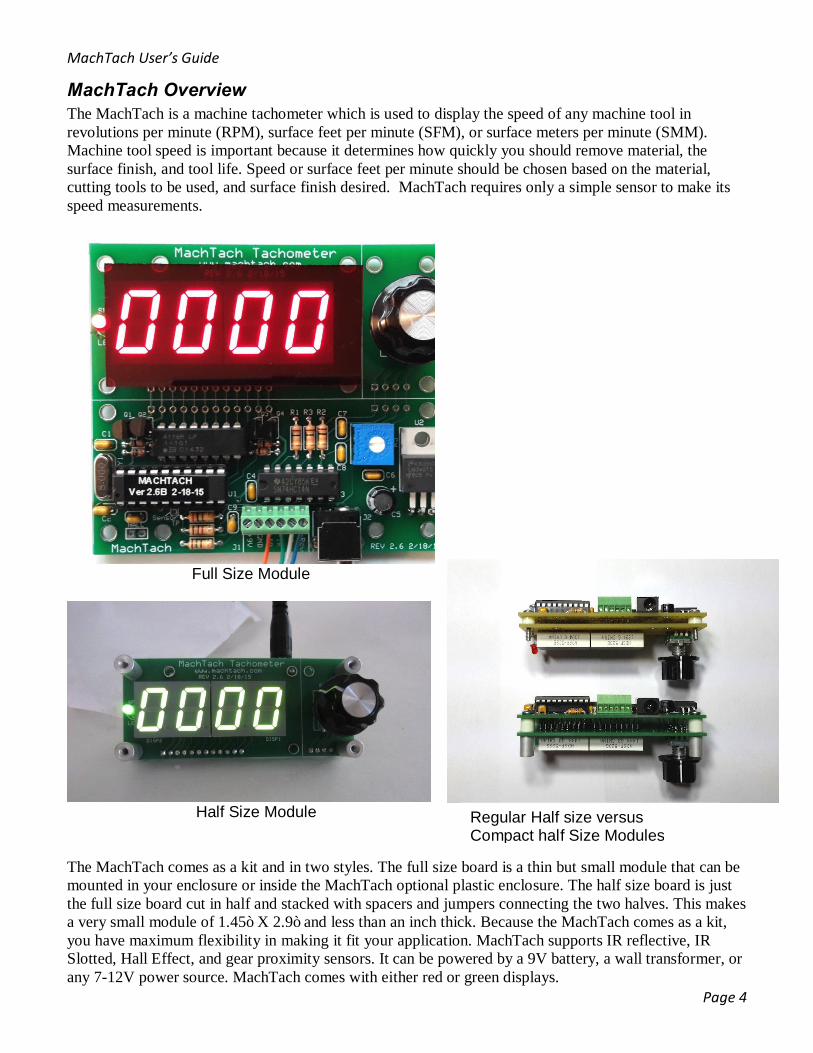
MachTach Overview The MachTach is a machine tachometer which is used to display the speed of any machine tool in revolutions per minute (RPM), surface feet per minute (SFM), or surface meters per minute (SMM). Machine tool speed is important because it determines how quickly you should remove material, the surface finish, and tool life. Speed or surface feet per minute should be chosen based on the material, cutting tools to be used, and surface finish desired. MachTach requires only a simple sensor to make its speed measurements.
Full Size Module
Half Size Module The MachTach comes as a kit and in two styles. The full size board is a thin but small module that can be mounted in your enclosure or inside the MachTach optional plastic enclosure. The half size board is just the full size board cut in half and stacked with spacers and jumpers connecting the two halves. This makes a very small module of 1.45” X 2.9” and less than an inch thick. Because the MachTach comes as a kit, you have maximum flexibility in making it fit your application. MachTach supports IR reflective, IR Slotted, Hall Effect, and gear proximity sensors. It can be powered by a 9V battery, a wall transformer, or any 7-12V power source. MachTach comes with either red or green displays.
Regular Half size versus Compact half Size Modules

MachTach User’s Guide
Page 5
Features: Five Modes of Operation
Revolutions per Minute mode - 0-9999 RPM Surface Feet per Minute mode - 0-9999 SFM or Surface Meters per Minute (Metric) - 0-9999 SMM Diameter Entry Mode for SFM/SMM -
0.01” – 99.99” (0.01” increments) SAE or 0.1 - 999.9mm (0.1 mm increments) Metric Slot Entry Mode - You can program any number of encoder slots/targets/magnets/teeth 1-90
SAE/Metric mode Selection 1 second display update (2 second at slow RPMs) Rotary encoder knob w/ push action switch for mode change, slot/diameter entry, SAE/Metric selection The MachTach includes a socketed PIC microcontroller so it can be easily updated by replacing the IC. Four Module Configurations
3.3" x 2.9" x 0.5” Full Size Module that can be mounted in your enclosure or the Serpac SR031 3.3" x 1.45" x 1.0” Half Size Module that can be mounted in your enclosure 3.3” x 1.45” x 0.80” Extra Compact Half Size Module using shorter spacers 4.375” x 3.25” x 0.9” Plastic Enclosure with laminated front panel
Slot and Diameter values are saved between sessions so they do not need to be re-entered SAE or Metric operation with mode selected saved between sessions Power: 7-12V at ~ 200 ma

MachTach User’s Guide
Page 6
Features for Version 2.6 MachTach recently had its PC Board and firmware updated. If you have the previous V2.4 or V2.5 kit, you should use the older manual which has the correct photos and instructions. Here are the new features for V2.6:
• The new PC board uses a terminal block instead of a connector. This makes it easier to connect the sensors without having to crimp small pins for a connector.
• The new board uses a more standard 5.5mm X 2.1mm power connector and power can also be applied through the terminal block. You are more likely to already have a wall transformer that you can be used with MachTach. As an example, the popular Arduino board uses the same transformer.
• The rotary encoder part has been improved. It is a little taller and works better with the knob. • On board VFD noise filtering has been added so that you only need the VFD filter in the worst
cases. • The new V2.6 firmware combines SAE and Metric Modes. Metric diameter entry is now 0.1mm
through 999.9mm (was 1-999mm) • The new firmware saves the last mode it was in (SFM/SMM or RPM) and powers up in the same
mode. The diameter, metric mode, and diameter are saved between each power up. • The diameter entry has been improved to be smoother. • New enclosure kits will ship with a factory produced overlay panel. The laminated panel was good
but the new panel is even better. The kit also includes a paper template for cutting the holes and a power jack which can be mounted in multiple places on the enclosure.
The new MachTach IC is not compatible with older versions of the board. The PC Board had some minor layout changes which makes the new firmware incompatible with the old PC Boards. This was the only downside of making PC Board changes. Mechanically the new PC Board has all the same hole, display, encoder locations. We do have a MachTach IC V2.6 for people with the previous MachTach revisions.
MachTach User’s Guide
Page 7
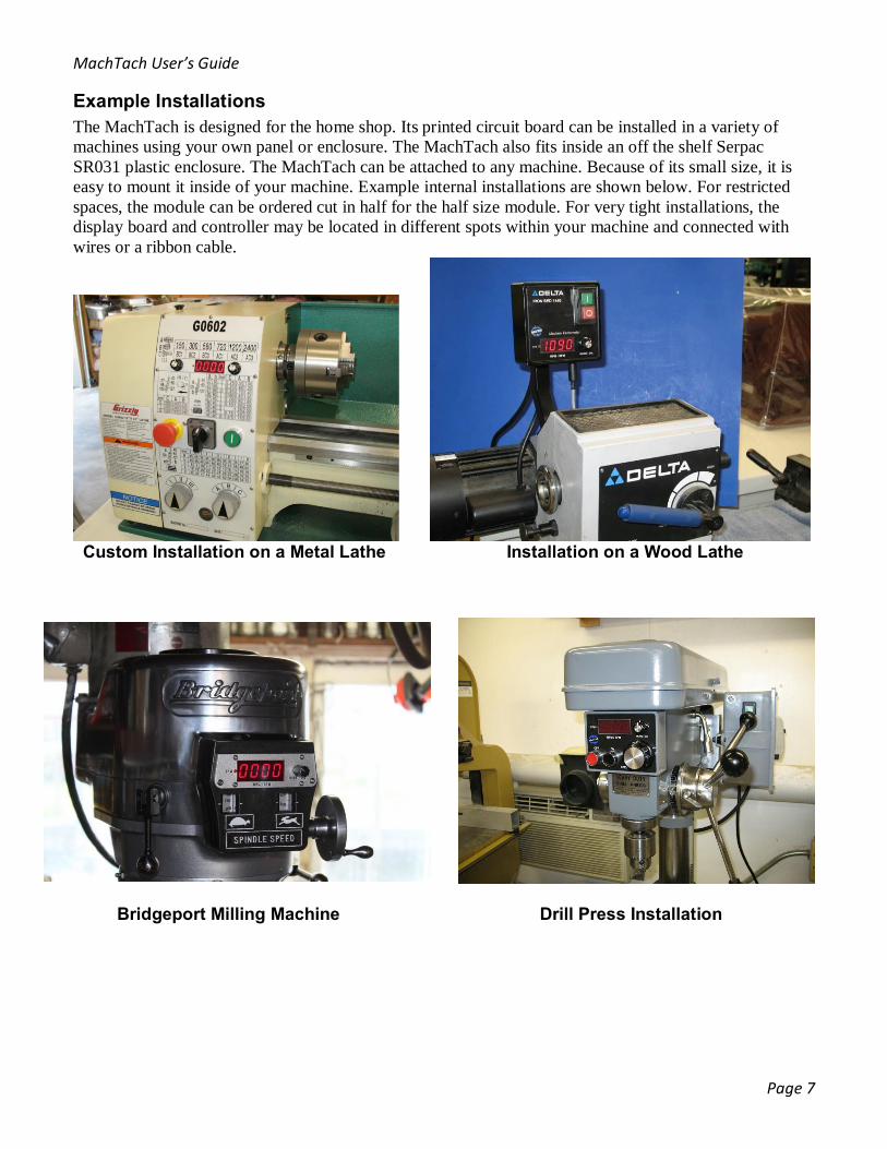
Example Installations The MachTach is designed for the home shop. Its printed circuit board can be installed in a variety of machines using your own panel or enclosure. The MachTach also fits inside an off the shelf Serpac SR031 plastic enclosure. The MachTach can be attached to any machine. Because of its small size, it is easy to mount it inside of your machine. Example internal installations are shown below. For restricted spaces, the module can be ordered cut in half for the half size module. For very tight installations, the display board and controller may be located in different spots within your machine and connected with wires or a ribbon cable.
Custom Installation on a Metal Lathe Installation on a Wood Lathe
Bridgeport Milling Machine Drill Press Installation

MachTach User’s Guide
Page 8
MachTach in a metal enclosure MachTach in custom painted metal enclosure
Lathe Gear Sensor Installation MachTach inside a Control Box
Lathe IR Reflective Installation
MachTach User’s Guide
Page 9
Using the MachTach The MachTach uses a single knob to control the modes and for entering the diameter of your lathe work or your end mill. The knob action is intuitive and easy to learn. The MachTach powers up in RPM mode - turning the knob does nothing in this mode. Pushing the encoder knob switches back and forth between RPM and SFM modes. An LED at the left of the display indicates SFM/SMM mode. In SFM mode, turning the knob automatically switches to diameter entry mode allowing the diameter 0.01" - 99.99" to be entered (0.1-999.9mm for Metric mode). Diameter entry mode exits automatically as soon as you stop turning the knob after a 1 second delay. Diameter mode exits back to SFM mode. In any mode, holding the knob in for greater than 5 seconds, puts the MachTach into slot entry mode and the SAE/Metric mode selection. In slot entry mode, you can enter the number of slots 1-90 by turning the knob. The slot number is used to calculate RPM based on the number of magnets/slots/reflectors/gear teeth for your installation. You exit the slot mode by pushing the knob once. As of version 2.6 of the MachTach firmware there is one more menu after the slot entry which allows you to select either SAE or Metric mode for the diameter entry and surface speed display. The slot entry mode and SAE/Metric mode are designed to not be entered easily since they should be needed infrequently. Slot entry and diameter entry modes enter and exit differently. With slot entry mode, the user has to push the knob and hold it to enter the mode and again to confirm the number of slots which is permanently saved to EEPROM. With diameter entry mode, the user is able to turn the knob while the MachTach is displaying SFM without having to click to enter. This allows the user to continuously change the diameter on the fly by just turning the knob. When you stop turning the knob, MachTach automatically switches to displaying SFM again. The diameter is saved each time you stop turning the knob and persists between power ups of the MachTach.
Using the RPM Mode By default the MachTach powers up in RPM mode. If the SFM/SMM mode was last used, it powers up in that mode. The SFM LED to the left of the display is off when in the RPM mode. In RPM mode, turning the knob will do nothing because the diameter does not matter for RPM calculations. Pressing the knob once will switch to SFM/SMM mode. Pressing the knob again will switch back to RPM mode.
Using the SFM Mode To enter SFM/SMM mode, press the knob once and the SFM LED to the left of the display will be lit. In SFM display mode, turning the knob will set the diameter you want. Once you start turning the knob, the display will automatically switch to 4 digits with a decimal point (XX.XX) which will allow you to set 0.01" through 99.99" as the diameter (0.1-999.9 mm for Metric). For milling machines, you should enter the diameter of your end mill. For lathes, you should enter the diameter of the work you are turning. When you stop turning the knob, the display will automatically revert to SFM/SMM mode. Pushing the knob again will return to the RPM display mode which will be indicated by the SFM LED going out. In diameter entry mode turning the knob quickly will increase or decrease the diameter quickly while turning it slowly will change the diameter by hundredths of inches or tenths of millimeters in Metric mode. You may enter the diameter of your work for lathes and the diameter of your milling tool for milling machines. Surface feet per minute calculations work the same whether the work is turning or the tool is turning. With lathes you will need to update the diameter as you remove material. Lathe work is an important application of the MachTach because turning large diameter work at too great of an RPM can cause excessive speed at the tool edge which can affect your surface finish or tool life.

MachTach User’s Guide
Page 10
Setting the Slot Number One of MachTach’s flexibilities is that you can set the number of slots/patches/magnets/gear teeth being used on your machine. To set the number of slots, magnets, reflective patches, or gear teeth, push in on the knob and hold it for greater than 5 seconds which will put the MachTach in slot entry mode. The center two digits will light up with a number like “01” displayed with no decimal place. Turn the knob to set the number of slots/magnets/targets/teeth to 01-90. Push the knob again to exit slot entry mode and enter SAE/Metric select mode. The slot number you entered is stored permanently until you enter a new number. The slot number is used to for all surface speed calculations and is the number of slots on your IR encoder wheel, the number of magnets used with your Hall Effect sensor, or the number of black and white patches on your black target when using IR reflective sensors. The MachTach also works with inductive gear tooth proximity sensors. Use the slot mode to enter the number of gear teeth.
SAE/Metric Mode Select The MachTach can display surface speed in Surface Feet per Minute (SFM) or Surface Meters per Minute (SMM) in the Metric mode. The selection of whether the MachTach operates in SAE or Metric is after the slot selection when you hold the encoder knob in for greater than 5 seconds. After you enter the number of slots you are using, press the knob again and the SAE/MEt menu will appear. Turn the knob left for SAE and right for Metric which appears as “MEt”. Press the knob again which exits both slot and SAE menus and returns to RPM mode.
What is Saved Between Power-ups MachTach has always saved the number of slots and the work diameter you entered. As of version 2.6, it will also save the SAE/Metric mode setting, the last diameters for both SAE and Metric modes, and the last mode either RPM or SFM/SMM. The RPM-SFM mode being saved allows the MachTach to power up in SFM mode if you left your MachTach in that mode and it will load the last used diameter setting. The following page summarizes how the modes work.

MachTach User’s Guide
Page 11
MachTach IC Version 2.6

MachTach User’s Guide
Page 12
How the MachTach Calculates RPM and SFM Feel free to skip this section if you are not interested in how the MachTach works. The MachTach works by measuring the time between sensor pulses. The time is measured in microseconds over a period of 1 second at moderate and fast speeds and over a period of 2 seconds for slow speeds. The MachTach averages the readings which gives a smoother display reading. RPM is calculated using the following formula: Revolutions per Minute:
RPM = ((1,000,000 microseconds / number of slots) / time between pulses in microseconds ) x 60 seconds
Surface feet per minute is calculated using the formula: SFM = (RPM x (diameter in hundredths of inches) x 314) / 120000 Surface meters per minute is calculated using the formula: SMM = (RPM x (diameter in tenths of millimeters) x 314) / 1000000 You may wonder if there is an advantage to using more than one slot or patch. It would seem like one slot should be enough. One slot or patch is enough to get an accurate RPM reading but using more slots or patches allows the MachTach to see more pulses at low speeds and to average those pulse times to give a smoother display. It also allows the MachTach to work down to lower RPMs. More patches or magnets do not increase accuracy. As long as the MachTach sees the time between two pulses, it is accurate. The MachTach code is written with the C language and is programmed into a Microchip PIC16F690 microprocessor. The MachTach uses two timers, one that measures an accurate 1 or 2 second interval which is used to update the display and to restart the capture process and another timer that measures the time from one rising pulse of the input pulse stream to the next rising pulse. During each 1 second display update interval, the MachTach measures as many pulse durations as it can and keeps track of how many it captured. When the 1 second interval is complete, the MachTach divides the total time of all pulse captured by the total number of pulses captured. This gives it the average pulse period which it then uses to calculate the RPM and SFM. One of the tricks the MachTach uses is to scale constants such. For example; 1 second = 1,000,000 microseconds and PI = 314. This scaling allows all calculations to be performed with integers instead of floating point numbers. This is important when using an 8 bit processor to keep things fast. During the endless loop of capturing pulse durations and displaying the result, the MachTach checks if the average pulse duration gets longer than a certain threshold. If it does, it switches from the normal 1 second update to a 2 second capture and update. The threshold is around 100 RPMs. This allows the MachTach to better display low RPMs down to single digits. This was necessary because below 60 RPM and low numbers of slots, there may not be a pulse to measure. The MachTach uses a rotary encoder on the front panel for user inputs. The MachTach reads both clockwise, counterclockwise, and push button actions of the rotary encoder input device. The MachTach debounces the encoder outputs and determines direction. It also determines how fast the knob is turning and how long the knob is pressed. A fast turn of the knob while entering the diameters increases or decreases the numbers quickly and slowly turning the knob changes it by single digits. This allows entering a large number like 12.95” (1295) to go quickly and moving from 0.55 to 0.60 ( 55 to 60) to move one number at a time.

MachTach User’s Guide
Page 13
Depressing the knob for greater than 5 seconds causes the MachTach to enter slot entry mode with one additional click exiting that mode and entering the SAE/Met selection. Another push exits SAE/Met mode. A quick press takes you from RPM mode to SFM mode. In SFM mode, turning the knob takes you into diameter entry mode which exits 1 second after you stop turning the knob. These actions are governed by a state machine which keeps track of modes and how long different entries of the knob take.
MachTach Lowest Displayable RPM The number of magnets, slots, patches, teeth determines the lowest speed displayable on the MachTach. The MachTach measures time between pulses and it waits as long as 2 seconds for a pulse. Because the MachTach measures time between pulses, it must see at least 1 set of encoder targets within 2 seconds or it will display zero. 6 magnets, slots, or patches will give you a lowest displayable speed of 5 RPM. 12 magnets will give you a lowest displayable speed of 2-3 RPM. The Following table summarizes the lowest displayable speed possible for a given number of Magnets/Slots/Patches:
Magnets/Slots/Patches/Gear Teeth Lowest Displayable RPM 1 30 2 15 4 7 6 5 12 2 30 1
Lowest Displayable RPM for Number of Targets
The number of slots/patches/magnets does not increase accuracy. It merely determines the slowest speed which can be measured. The MachTach always displays to the nearest 1 RPM. Sometimes people will notice jitter in the measurement of a few RPMs. This can be caused by uneven spacing of the strips.

MachTach User’s Guide
Page 14
Review of MachTach Sensors The MachTach is designed to support many different types of sensors including IR Reflective, IR Slotted/Interruptive, Hall Effect, and Gear Tooth Proximity. Each of these sensors has different strengths and weaknesses. The IR Reflective sensor is a good all-around sensor, works well in many situations, and is included by default with each MachTach kit.
IR Reflective Sensors IR Reflective Sensors work well in a relatively clean environment where dust will not affect their operation. They are easy to install using a simple bracket and reflective tape on a dark background. They work great inside of machine boxes which do not have oil spray or dust entering the enclosure. The IR sensor works in total darkness because it shines its own IR light on the patch and then picks up the reflection. IR is invisible to the human eye so you can’t see if it is working. Sometimes a digital camera or smart phone can see the IR light. Try it out. The MachTach is supplied with an IR Reflective Sensor and a strip of reflective material. The reflective material can be cut into patches and attached to almost any rotating object to be used as a target for the reflective IR sensor. The reflective material should be attached to something with a dark background such as something painted flat black. Once you install the reflective patches, count the number of reflective patches and enter that number into the slot entry mode of the MachTach. Mount the sensor close (about .15”-.20”) and you will be able to measure RPM and SFM. The patches must be mounted with uniform spacing otherwise the stability of the RPM display will be affected although only by a small amount.
IR Reflective Sensor inside the Head of a metal Lathe – Using a custom Bracket

MachTach User’s Guide
Page 15
Example IR Reflective Bracket Mounting and Tape Patches
IR Reflective Sensor inside of Head of Metal Lathe

MachTach User’s Guide
Page 16
IR Slot Sensors The MachTach also works with IR Slot or Interrupt sensors with slotted or holed encoder wheels. Slotted IR Sensors are good when you can drill some small holes in an existing flange or pulley. For example, I’ve seen people drill small holes in the edge of a pulley. Slotted sensors can also be used with a small slotted wheel mounted on the end of a shaft or spindle. Some people add these to a lathe spindle inside the pulley/gear box of the lathe. Slotted sensors are less susceptible to dust or grease but are usually a little more difficult to construct and install then IR reflective sensors.
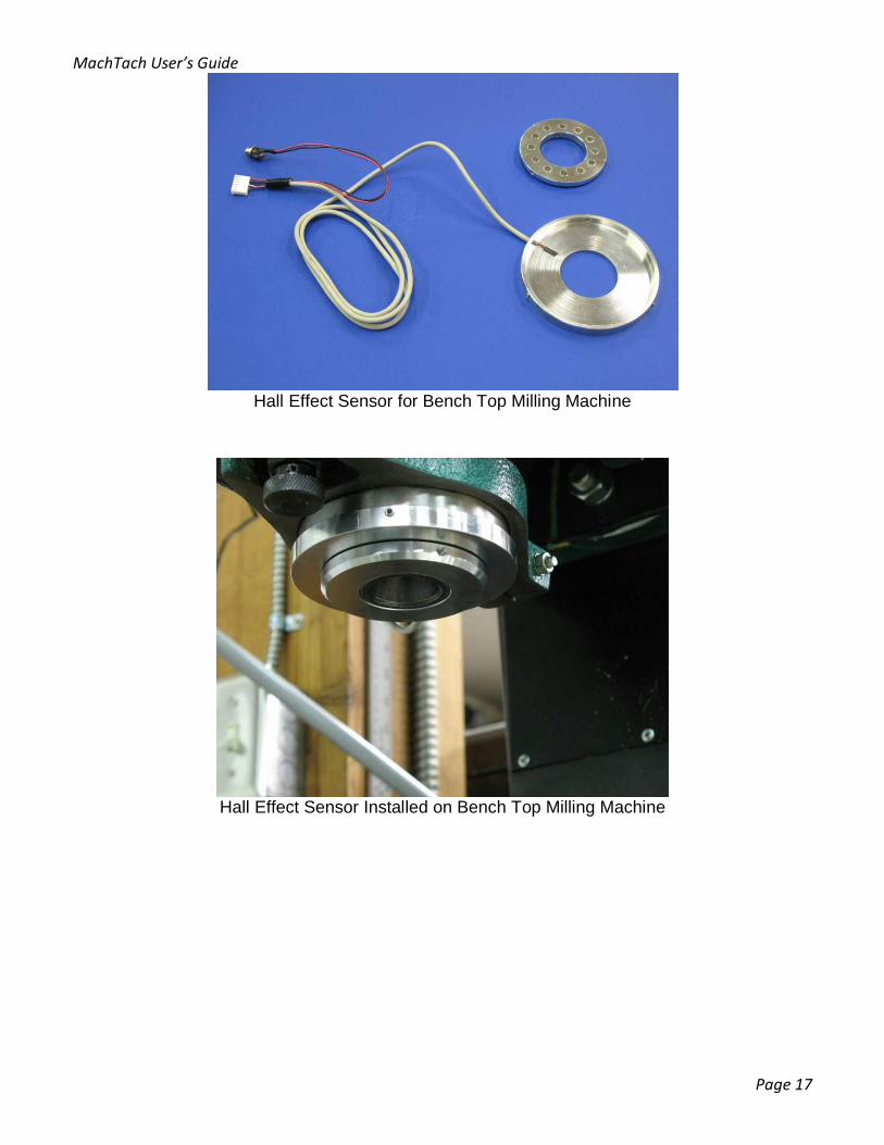
Hall Effect Sensors Hall Effect sensors respond to small magnet/magnets on the rotating spindle. Hall Effect Sensors are good in harsh environments where there is dust, oil, or other liquids. I used a Hall Effect sensor on my milling machine because I wanted to sense the spindle speed which is near where cutting oil or debris might hit it. I still enclosed the sensor which protects it but it would have been more difficult to mount an IR sensor in the same location
Hall Effect Sensor in its Housing and the Matching Magnet Ring
Hall Effect sensors are good for dirty environments where a reflective or slotted IR sensor might get fouled with oil or debris. The magnets must be mounted with uniform spacing otherwise the stability of the RPM display will be affected.
MachTach User’s Guide
Page 17
Hall Effect Sensor for Bench Top Milling Machine
Hall Effect Sensor Installed on Bench Top Milling Machine
MachTach User’s Guide
Page 18
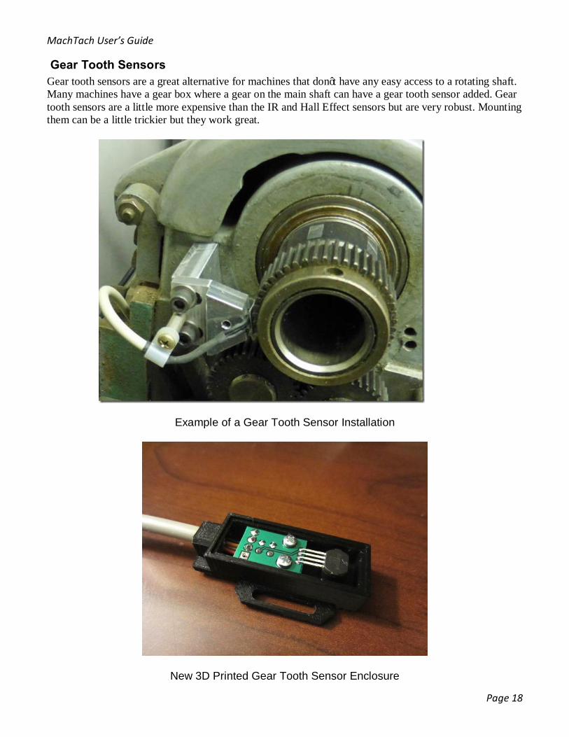
Gear Tooth Sensors Gear tooth sensors are a great alternative for machines that don’t have any easy access to a rotating shaft. Many machines have a gear box where a gear on the main shaft can have a gear tooth sensor added. Gear tooth sensors are a little more expensive than the IR and Hall Effect sensors but are very robust. Mounting them can be a little trickier but they work great.
Example of a Gear Tooth Sensor Installation
New 3D Printed Gear Tooth Sensor Enclosure

MachTach User’s Guide
Page 19
Other Sensors The MachTach is designed to use any sensor with an open collector or transistor output. The MachTach can supply 5V to the sensor and it can accept a 0-5V output signal from the sensor. Almost all sensors fit these requirements. The MachTach is able to deal with noisy signals because it has a noise conditioning front end with hysteresis. As long as the selected sensor has a transistor output that can swing at least 1-4V, it will probably work with the MachTach.
MachTach User’s Guide
Page 20
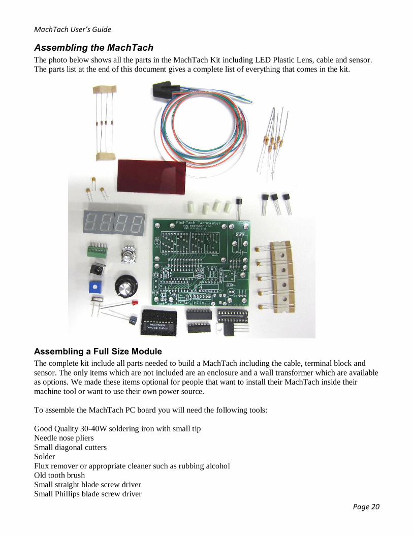
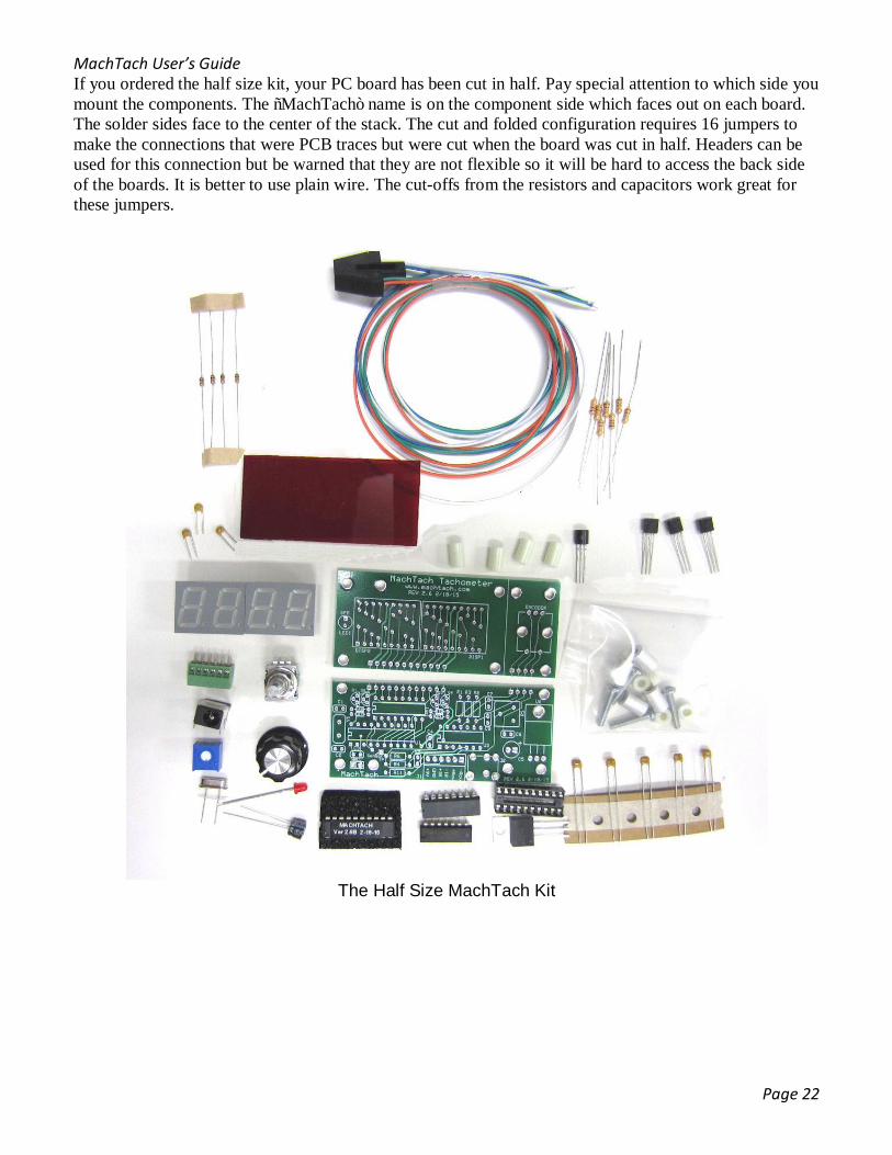
Assembling the MachTach The photo below shows all the parts in the MachTach Kit including LED Plastic Lens, cable and sensor. The parts list at the end of this document gives a complete list of everything that comes in the kit.
Assembling a Full Size Module The complete kit include all parts needed to build a MachTach including the cable, terminal block and sensor. The only items which are not included are an enclosure and a wall transformer which are available as options. We made these items optional for people that want to install their MachTach inside their machine tool or want to use their own power source. To assemble the MachTach PC board you will need the following tools: Good Quality 30-40W soldering iron with small tip Needle nose pliers Small diagonal cutters Solder Flux remover or appropriate cleaner such as rubbing alcohol Old tooth brush Small straight blade screw driver Small Phillips blade screw driver

MachTach User’s Guide
Page 21
The following pages include a parts layout diagram, the schematic and the parts list to help you with placing parts. The parts layout diagram shows the top layer with the part designations and outlines. Be careful when installing parts to get them in the correct holes.
NOTE: If you are planning to install your MachTach in the Serpac Enclosure, you should not install the J2 power connector and instead use the supplied panel mount power connector. Although the PCB J2 connector can poke out of the Serpac enclosure, its placement may not be convenient when mounting your MachTach. The panel mount connector can be mounted multiple locations on the enclosure. There will be more explanation regarding this in the section on modifying the Serpac Enclosure. Sensor terminal block J1 should be mounted on the backside of the board for Serpac Enclosure use.
MachTach User’s Guide
Page 22
If you ordered the half size kit, your PC board has been cut in half. Pay special attention to which side you mount the components. The “MachTach” name is on the component side which faces out on each board. The solder sides face to the center of the stack. The cut and folded configuration requires 16 jumpers to make the connections that were PCB traces but were cut when the board was cut in half. Headers can be used for this connection but be warned that they are not flexible so it will be hard to access the back side of the boards. It is better to use plain wire. The cut-offs from the resistors and capacitors work great for these jumpers.
The Half Size MachTach Kit
MachTach User’s Guide
Page 23
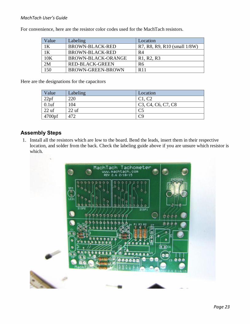
For convenience, here are the resistor color codes used for the MachTach resistors.
Value Labeling Location 1K BROWN-BLACK-RED R7, R8, R9, R10 (small 1/8W) 1K BROWN-BLACK-RED R4 10K BROWN-BLACK-ORANGE R1, R2, R3 2M RED-BLACK-GREEN R6 150 BROWN-GREEN-BROWN R11
Here are the designations for the capacitors
Value Labeling Location 22pf 220 C1, C2 0.1uf 104 C3, C4, C6, C7, C8 22 uf 22 uf C5 4700pf 472 C9
Assembly Steps 1. Install all the resistors which are low to the board. Bend the leads, insert them in their respective
location, and solder from the back. Check the labeling guide above if you are unsure which resistor is which.

MachTach User’s Guide
Page 24
2. Clip the leads from the back.
3. Install the ceramic capacitors C1, C2, and C9 which are also low to the board. Be extra careful to check each capacitor’s labeling. They all look the same but have different values. C1 and C2 are labeled 220 and C9 is labeled 472. It is very important to get these in the correct location.

MachTach User’s Guide
Page 25
4. Install the ceramic capacitors C3, C4, C6, C7, and C8. These capacitors are all the same and are labeled 104. They usually come in the kit on a paper strip. I don’t have a photo of this step.
5. Install resistor network RN1 which can be labeled 101, 820, or 750 depending on your kit LED color. Install 74HC14 U3, trimmer R5, and the crystal with its insulator. You can solder these one at a time or all at once. Tack them in place; make sure they are all flush to the board, and then soldering the remaining pins.
Example Solder Joints
MachTach User’s Guide
Page 26
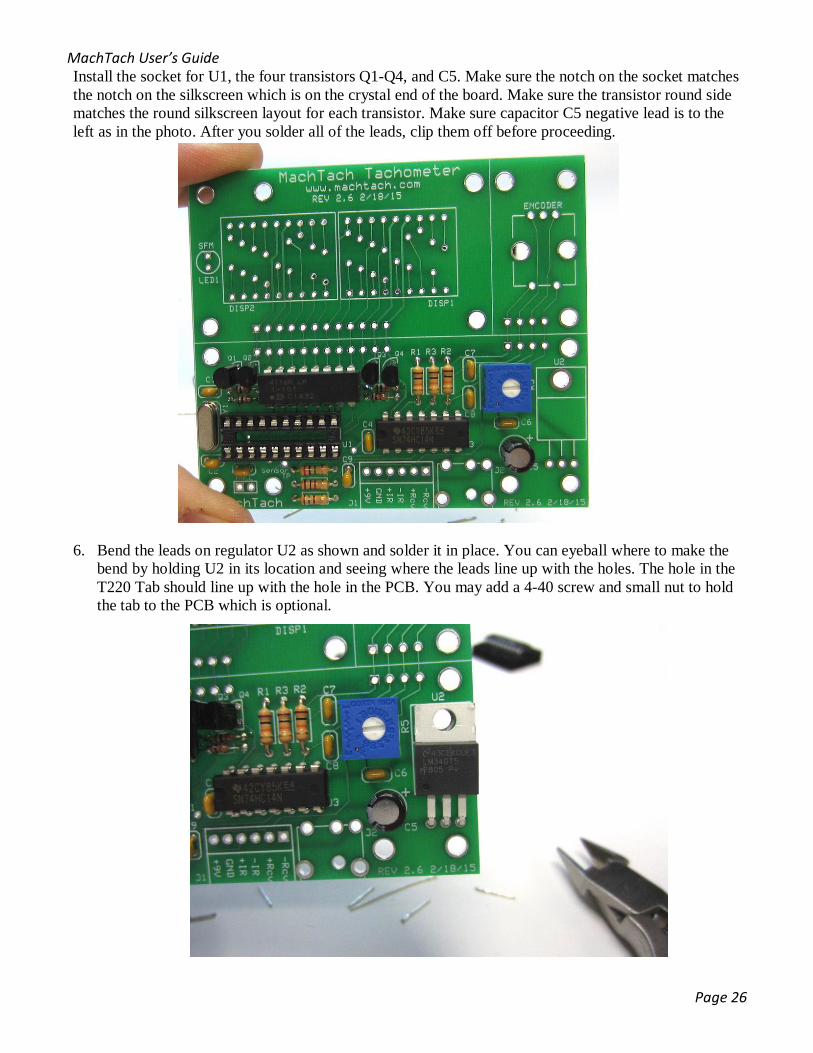
Install the socket for U1, the four transistors Q1-Q4, and C5. Make sure the notch on the socket matches the notch on the silkscreen which is on the crystal end of the board. Make sure the transistor round side matches the round silkscreen layout for each transistor. Make sure capacitor C5 negative lead is to the left as in the photo. After you solder all of the leads, clip them off before proceeding.
6. Bend the leads on regulator U2 as shown and solder it in place. You can eyeball where to make the
bend by holding U2 in its location and seeing where the leads line up with the holes. The hole in the T220 Tab should line up with the hole in the PCB. You may add a 4-40 screw and small nut to hold the tab to the PCB which is optional.
MachTach User’s Guide
Page 27
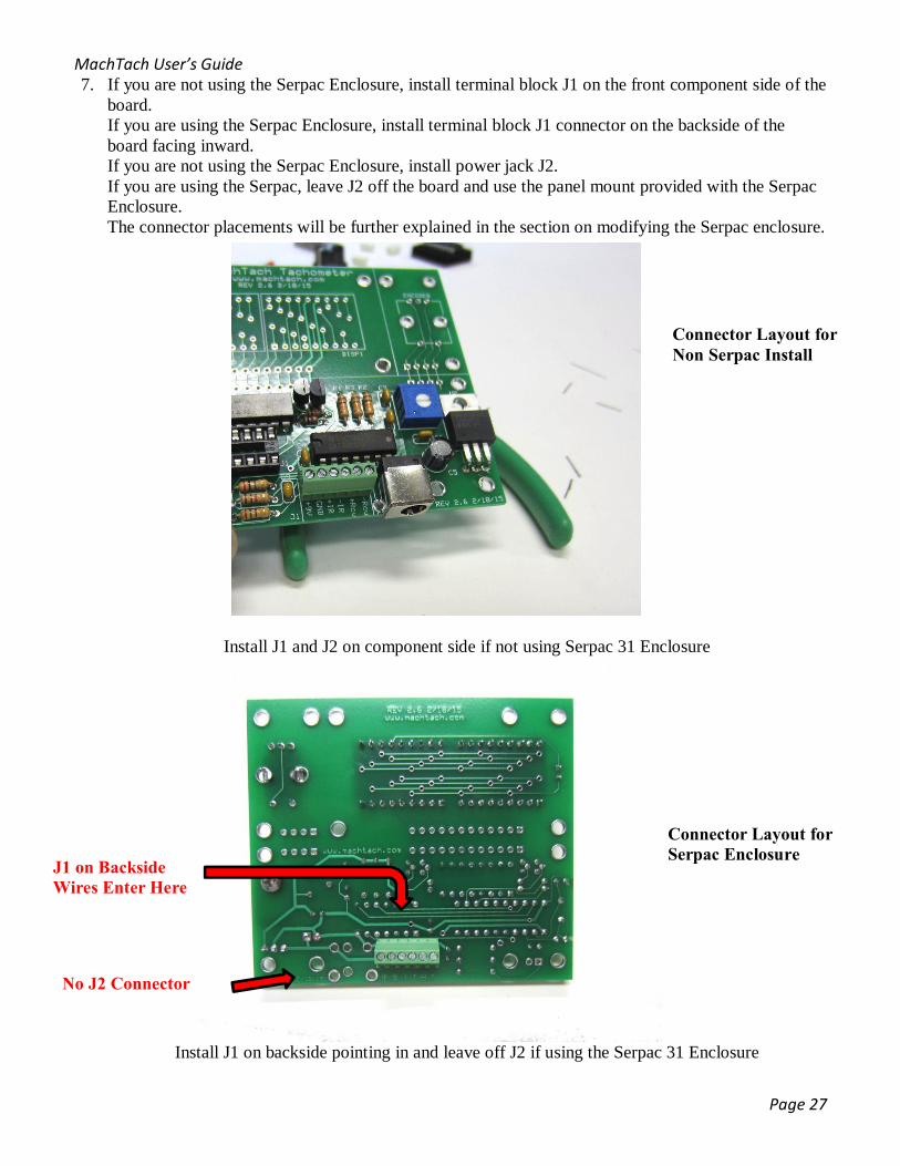
7. If you are not using the Serpac Enclosure, install terminal block J1 on the front component side of the board. If you are using the Serpac Enclosure, install terminal block J1 connector on the backside of the board facing inward. If you are not using the Serpac Enclosure, install power jack J2. If you are using the Serpac, leave J2 off the board and use the panel mount provided with the Serpac Enclosure. The connector placements will be further explained in the section on modifying the Serpac enclosure.
Install J1 and J2 on component side if not using Serpac 31 Enclosure
Install J1 on backside pointing in and leave off J2 if using the Serpac 31 Enclosure
J1 on Backside Wires Enter Here
Connector Layout for Non Serpac Install
Connector Layout for Serpac Enclosure
No J2 Connector

MachTach User’s Guide
Page 28
8. Install the two displays paying extra attention to make sure they mounted with the decimal points towards the middle of the board and that they are aligned straight. Tack two pins first, check the alignment and that the displays are flush to the board before soldering the rest of the pins.
9. Install LED1. Make sure the flat portion of the skirt is pointing in the direction shown on the
silkscreen which is towards the top edge of the board. The top of the LED should be level with the two displays and centered. If your LED does not have a flat portion of the skirt, the long lead (anode) goes in the round pad hole not the square pad hole. You may also elect to mount the LED higher (as shown below) than the displays so it pokes through the panel of the Serpac enclosure. Make sure it is perpendicular to the board.
MachTach User’s Guide
Page 29
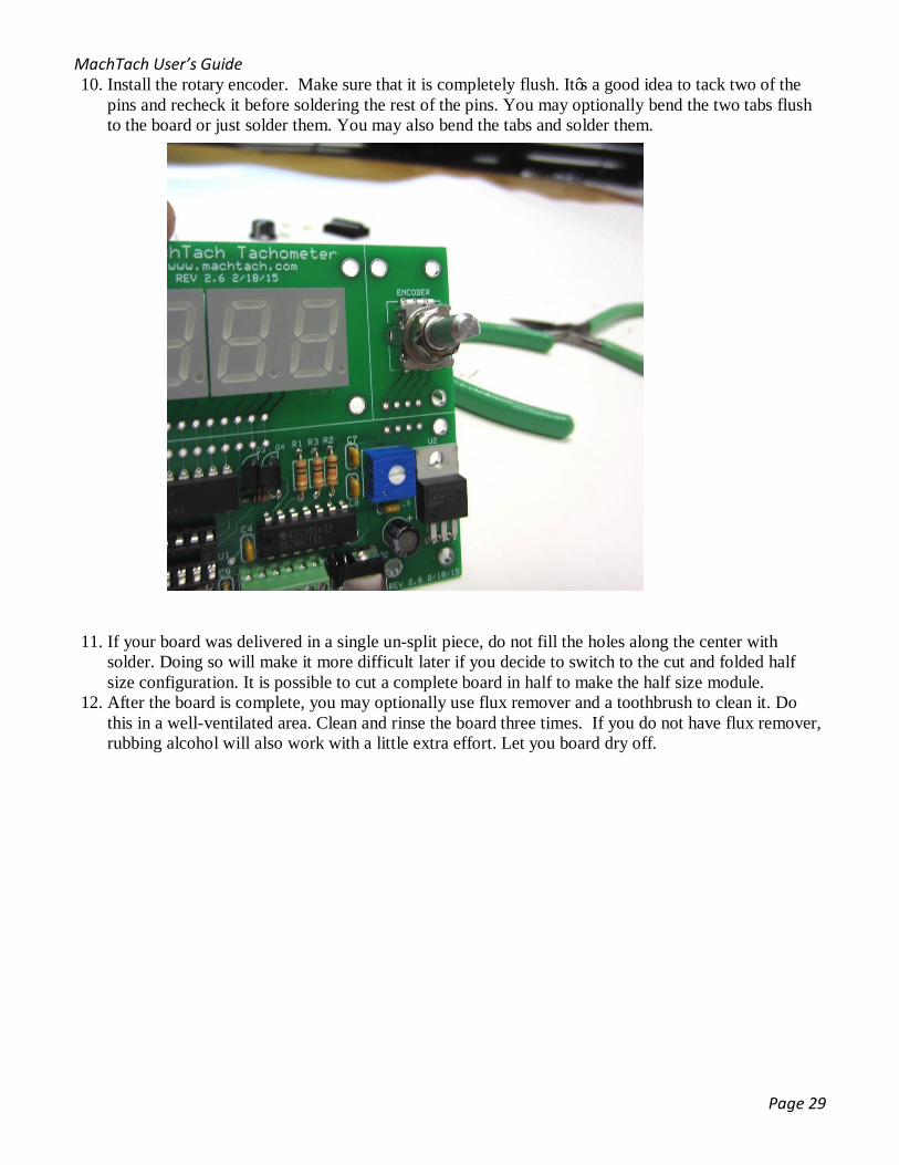
10. Install the rotary encoder. Make sure that it is completely flush. It’s a good idea to tack two of the pins and recheck it before soldering the rest of the pins. You may optionally bend the two tabs flush to the board or just solder them. You may also bend the tabs and solder them.
11. If your board was delivered in a single un-split piece, do not fill the holes along the center with solder. Doing so will make it more difficult later if you decide to switch to the cut and folded half size configuration. It is possible to cut a complete board in half to make the half size module.
12. After the board is complete, you may optionally use flux remover and a toothbrush to clean it. Do this in a well-ventilated area. Clean and rinse the board three times. If you do not have flux remover, rubbing alcohol will also work with a little extra effort. Let you board dry off.

MachTach User’s Guide
Page 30
13. Use compressed air to dry the board if available.
14. Install the microcontroller U1. You will need to pre-bend the leads against a flat surface so they are
vertical so that the IC easily installs in the socket. Make sure the IC notch faces left towards the crystal.
15. If you will be using the Hall Effect or gear tooth sensors, solder a jumper at the location labeled HALL in the lower left corner. Do not install this jumper if you are using IR sensors. It may damage an IR sensor because it will apply 5V directly to the IR LED.
Completed Front side of the MachTach
MachTach User’s Guide
Page 31
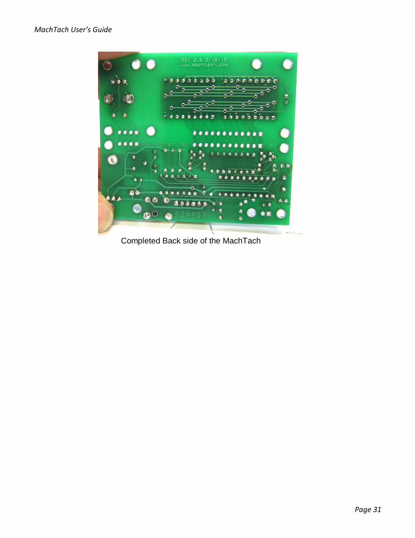
Completed Back side of the MachTach

MachTach User’s Guide
Page 32
Assembling a Half Size Module The Full Size MachTach PCB can be cut in half and assembled as a half size module. You may order your kit with the board already split. Cutting the board in half disconnects 16 traces which are reconnected with jumpers as shown in the following photos. The module will also need the supplied 0.250” plastic standoffs to hold the boards apart.
Half Size Module before assembly with Spacers
Each side of the board is assembled the same as a full size module. Use the instructions in the previous section to assemble the boards. Make sure all of your leads are trimmed short enough to not touch when the boards are mounted back to back. The two boards are then mounted back to back using standoffs. The 4-40 machine screws are fed through the bottom board, the spacer, the top display board, and then are retained using the threaded spacer. You will need to make a total of 32 solder connections on your 16 jumpers. To jumper the module, just feed wire through all 16 pairs of holes and solder pads on both boards. See the photos to see how the jumpers are installed. Note: The kit is supplied with 1/4” or 1/8”spacers. If you would like an even more compact module, use the supplied 1/8” spacers. Make sure all your leads are trimmed very short so they don’t touch across the front and back boards. This will reduce the thickness by 1/8”. You will have to trim the LED display pins when using the 1/8” spacers. Note: Use the ¼” spacers if you are using the 3D Printed Enclosure.
MachTach User’s Guide
Page 33
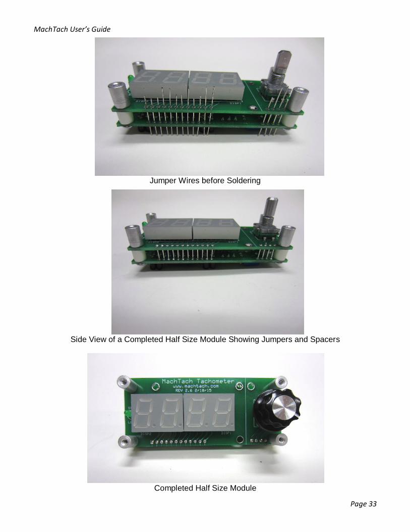
Jumper Wires before Soldering
Side View of a Completed Half Size Module Showing Jumpers and Spacers
Completed Half Size Module
MachTach User’s Guide
Page 34
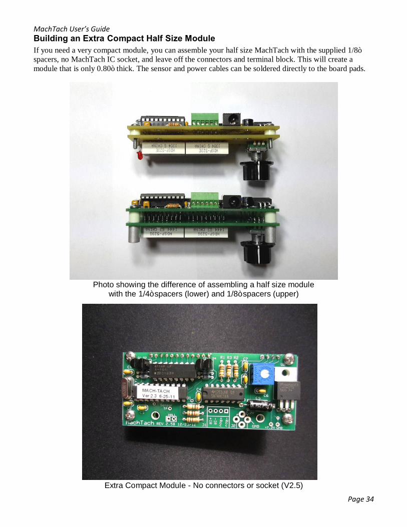
Building an Extra Compact Half Size Module If you need a very compact module, you can assemble your half size MachTach with the supplied 1/8” spacers, no MachTach IC socket, and leave off the connectors and terminal block. This will create a module that is only 0.80” thick. The sensor and power cables can be soldered directly to the board pads.
Photo showing the difference of assembling a half size module
with the 1/4” spacers (lower) and 1/8” spacers (upper)
Extra Compact Module - No connectors or socket (V2.5)
MachTach User’s Guide
Page 35
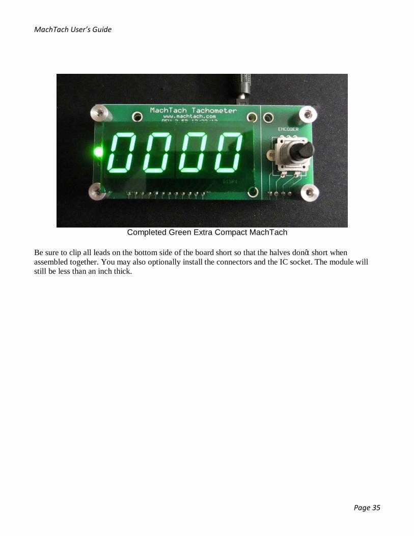
Completed Green Extra Compact MachTach
Be sure to clip all leads on the bottom side of the board short so that the halves don’t short when assembled together. You may also optionally install the connectors and the IC socket. The module will still be less than an inch thick.

MachTach User’s Guide
Page 36
Powering Up the MachTach The MachTach requires 7-9 VDC for power. You may use the optional DC wall transformer, a 9V battery, your own wall transformer, or other suitable DC supply. The optional wall transformer has a 5.5mm OD/2.1mm ID connector that mates with J2. You may also purchase the matching plug for J2 from us or you may connect directly to the labeled screw connectors on J1 terminal block. Be sure to get the polarity correct because there is no reverse polarity protection. The center of the J2/P2 connection is positive. The MachTach may also be optionally powered with 12 VDC by adding a heat sink to regulator U2 using a 4-40 size screw and nut. The heat sink is not included but is readily available.
Checking Out the MachTach Once you power up the MachTach, it should display “0000” and the SFM LED should be not light up. Try pressing the knob a few times and the SFM mode LED should go on and off. In SFM mode, try turning the knob. You should be able to enter diameters from 00.01” through 99.99” (0.1 – 999.9 mm for Metric). Last, try holding the knob in for 5 seconds to see if can enter the Slot Entry mode. Slot Entry mode allows values of 1-90. If you can’t perform any of the above checks, refer to the troubleshooting section of this manual.
Power by Direct Wired Connection or by Power Jack
Wiring the Optional Plug

MachTach User’s Guide
Page 37
Making Your Sensor Cable On previous MachTachs, the sensor cable used a connector with crimped pins. Because the mating connector could be mounted on either side of the PCB, there were two diagrams for each possible sensor cable. The new MachTach uses a screw terminal block that can be mounted on either side of the PCB. The connections are clearly labeled so connecting the sensor cable has been simplified.
Making the IR Sensor Cable with Sensors having Wires Recently we started shipping MachTach kits with IR sensors that already have 24” of wire. This eliminates the need to solder a cable onto the sensor. The sensor bag includes a 24 inch piece of protective tubing. Cut the tubing and wire to your desired length and then slide the four wires through the tubing. The tubing should be about 1.5” shorter than the wires so that the wires can poke out. Strip and tin the leads. Connect the four leads to the J1 terminal block on the MachTach as shown in the table and pictorial diagram.
Name IR Sensor Pin Number Wire Color +IR 1 Orange -IR 2 Green +RCV 4 White -RCV 3 Blue
IR Reflective Sensor Cable Wiring Table
Pictorial Wiring Diagram for IR Reflective Sensor with Factory Wires
This end points to reflective strip

MachTach User’s Guide
Page 38
Making the IR Sensor Cable If you have a kit with a grey sensor cable instead of a sensor with wire leads, cut your cable to the desired length and strip the outer covering to reveal the wires. A length of 36” is usually good. Slide a piece of 3/8” shrink wrap over the cable which will be used to protect the sensor end of the cable. Slide the 1/8” shrink warp over each of the wires which will connect to the sensor. Using needle nose pliers, make a small loop on each lead of the sensor. Solder each wire as shown in either the pictorial or table. Tin the four leads that go to the J1 terminal block on the MachTach.
Name IR Sensor Pin Number Suggested Wire Color +IR 1 Red -IR 2 Brown +RCV 4 Orange -RCV 3 Black/Yellow
IR Reflective Sensor Cable Wiring Table
Pictorial Wiring Diagram for IR Reflective Sensor Cable
Slide the 1/8” shrink wrap over each connection and shrink it using a heat gun. Place the large 3/8” shrink wrap over the end of the sensor but not over the slot. Using a heat gun shrink the wrap 3/8” wrap into place.
This end points to reflective strip
MachTach User’s Guide
Page 39
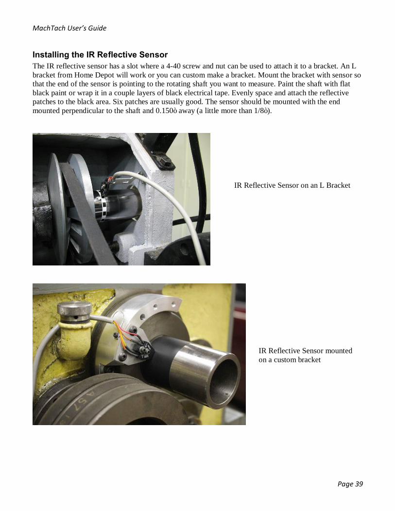
Installing the IR Reflective Sensor The IR reflective sensor has a slot where a 4-40 screw and nut can be used to attach it to a bracket. An L bracket from Home Depot will work or you can custom make a bracket. Mount the bracket with sensor so that the end of the sensor is pointing to the rotating shaft you want to measure. Paint the shaft with flat black paint or wrap it in a couple layers of black electrical tape. Evenly space and attach the reflective patches to the black area. Six patches are usually good. The sensor should be mounted with the end mounted perpendicular to the shaft and 0.150” away (a little more than 1/8”).
IR Reflective Sensor on an L Bracket
IR Reflective Sensor mounted on a custom bracket
MachTach User’s Guide
Page 40
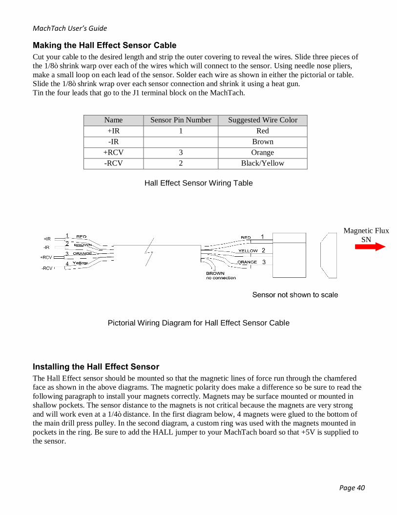
Making the Hall Effect Sensor Cable Cut your cable to the desired length and strip the outer covering to reveal the wires. Slide three pieces of the 1/8” shrink warp over each of the wires which will connect to the sensor. Using needle nose pliers, make a small loop on each lead of the sensor. Solder each wire as shown in either the pictorial or table. Slide the 1/8” shrink wrap over each sensor connection and shrink it using a heat gun. Tin the four leads that go to the J1 terminal block on the MachTach.
Name Sensor Pin Number Suggested Wire Color +IR 1 Red -IR Brown
+RCV 3 Orange -RCV 2 Black/Yellow
Hall Effect Sensor Wiring Table
Pictorial Wiring Diagram for Hall Effect Sensor Cable
Installing the Hall Effect Sensor The Hall Effect sensor should be mounted so that the magnetic lines of force run through the chamfered face as shown in the above diagrams. The magnetic polarity does make a difference so be sure to read the following paragraph to install your magnets correctly. Magnets may be surface mounted or mounted in shallow pockets. The sensor distance to the magnets is not critical because the magnets are very strong and will work even at a 1/4” distance. In the first diagram below, 4 magnets were glued to the bottom of the main drill press pulley. In the second diagram, a custom ring was used with the magnets mounted in pockets in the ring. Be sure to add the HALL jumper to your MachTach board so that +5V is supplied to the sensor.
Magnetic Flux SN
MachTach User’s Guide
Page 41
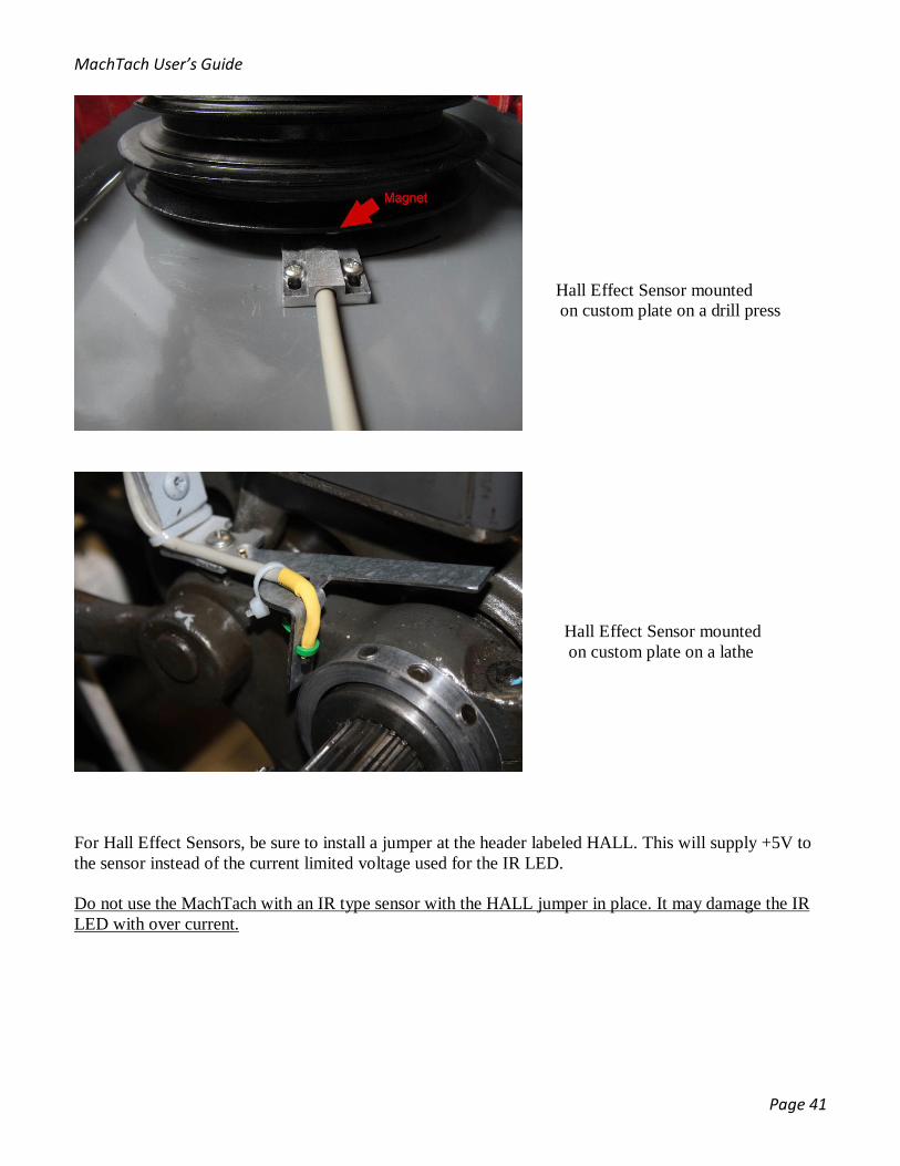
For Hall Effect Sensors, be sure to install a jumper at the header labeled HALL. This will supply +5V to the sensor instead of the current limited voltage used for the IR LED. Do not use the MachTach with an IR type sensor with the HALL jumper in place. It may damage the IR LED with over current.
Hall Effect Sensor mounted on custom plate on a drill press
Hall Effect Sensor mounted on custom plate on a lathe
MachTach User’s Guide
Page 42
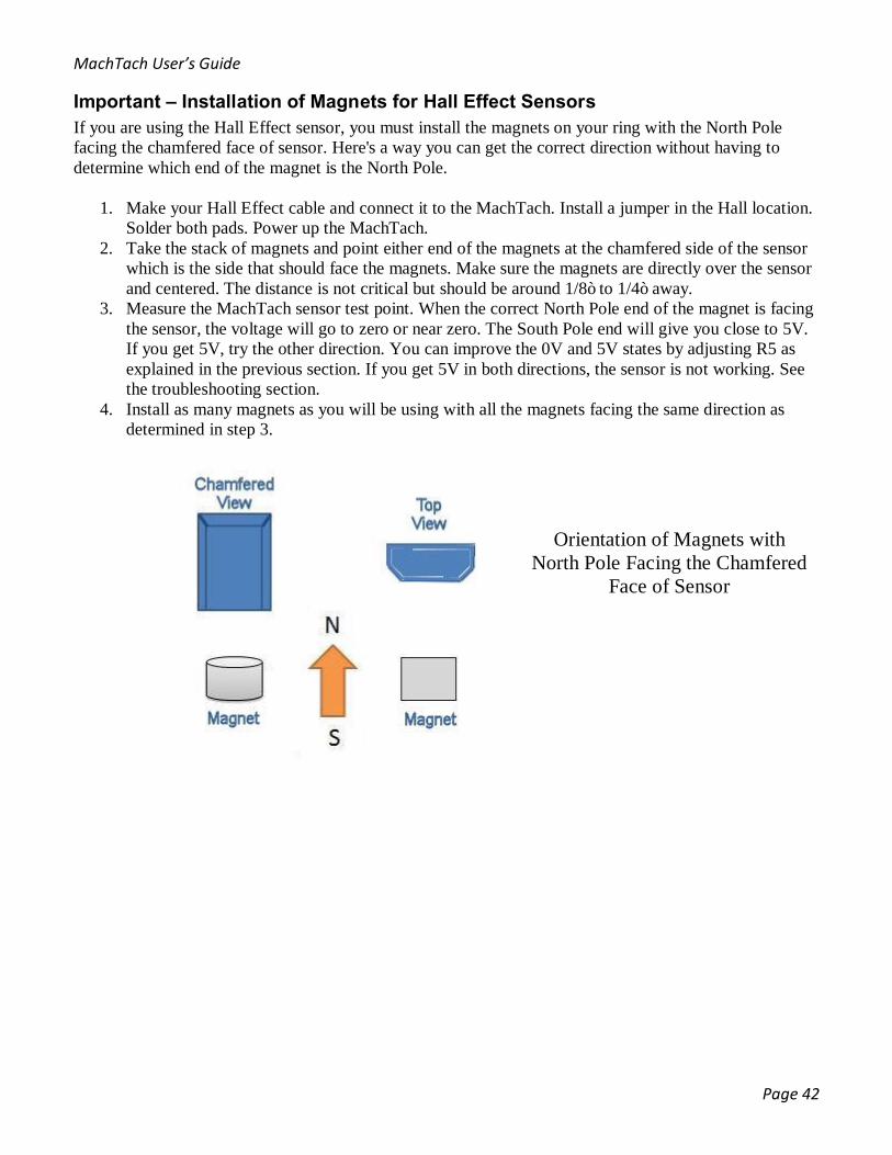
Important – Installation of Magnets for Hall Effect Sensors If you are using the Hall Effect sensor, you must install the magnets on your ring with the North Pole facing the chamfered face of sensor. Here's a way you can get the correct direction without having to determine which end of the magnet is the North Pole.
1. Make your Hall Effect cable and connect it to the MachTach. Install a jumper in the Hall location. Solder both pads. Power up the MachTach.
2. Take the stack of magnets and point either end of the magnets at the chamfered side of the sensor which is the side that should face the magnets. Make sure the magnets are directly over the sensor and centered. The distance is not critical but should be around 1/8” to 1/4” away.
3. Measure the MachTach sensor test point. When the correct North Pole end of the magnet is facing the sensor, the voltage will go to zero or near zero. The South Pole end will give you close to 5V. If you get 5V, try the other direction. You can improve the 0V and 5V states by adjusting R5 as explained in the previous section. If you get 5V in both directions, the sensor is not working. See the troubleshooting section.
4. Install as many magnets as you will be using with all the magnets facing the same direction as determined in step 3.
Orientation of Magnets with North Pole Facing the Chamfered
Face of Sensor

MachTach User’s Guide
Page 43
Making the IR Slotted Sensor Cable Cut your cable to the desired length and strip the outer covering to reveal the wires. Slide four pieces of the 1/8” shrink warp over each of the wires which will connect to the sensor. Using needle nose pliers, make a small loop on each lead of the sensor. Solder each wire as shown in either the pictorial or table. Slide the 1/8” shrink wrap over each sensor connection and shrink it using a heat gun. Tin the four leads that go to the J1 terminal block on the MachTach.
Name IR Sensor Pin Number Suggested Wire Color +IR 2 Red -IR 1 Brown +RCV 3 Orange -RCV 4 Black/Yellow
IR Slotted Sensor Wiring Table
NOTE: In this diagram the slot is facing up and the leads are on the bottom bent facing out.
Installing the IR Slotted Sensor The IR slotted sensor will require you to make either a slotted wheel or to bore holes or slots in an existing pulley flange or feature. The sensor can be mounted to a custom bracket so that the holes or slots move past the slot window. The sensor has two 4-40 size slots for mounting.
Example slotted sensor wheel and sensor
MachTach User’s Guide
Page 44
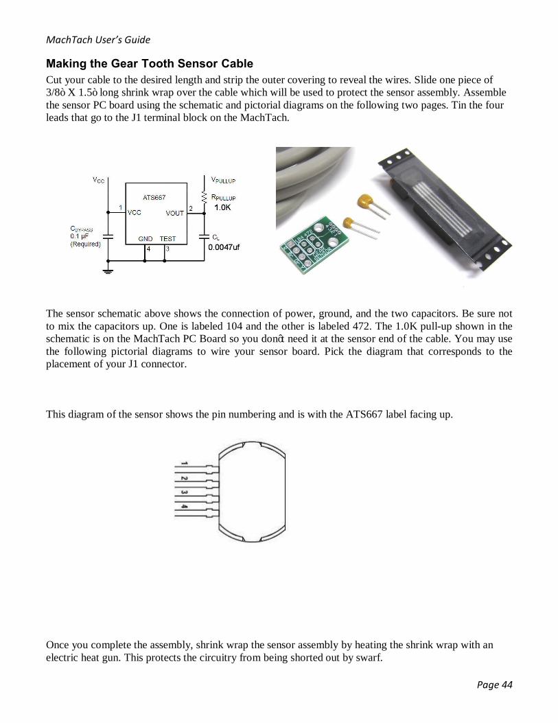
Making the Gear Tooth Sensor Cable Cut your cable to the desired length and strip the outer covering to reveal the wires. Slide one piece of 3/8” X 1.5” long shrink wrap over the cable which will be used to protect the sensor assembly. Assemble the sensor PC board using the schematic and pictorial diagrams on the following two pages. Tin the four leads that go to the J1 terminal block on the MachTach.
The sensor schematic above shows the connection of power, ground, and the two capacitors. Be sure not to mix the capacitors up. One is labeled 104 and the other is labeled 472. The 1.0K pull-up shown in the schematic is on the MachTach PC Board so you don’t need it at the sensor end of the cable. You may use the following pictorial diagrams to wire your sensor board. Pick the diagram that corresponds to the placement of your J1 connector. This diagram of the sensor shows the pin numbering and is with the ATS667 label facing up.
Once you complete the assembly, shrink wrap the sensor assembly by heating the shrink wrap with an electric heat gun. This protects the circuitry from being shorted out by swarf.
MachTach User’s Guide
Page 45
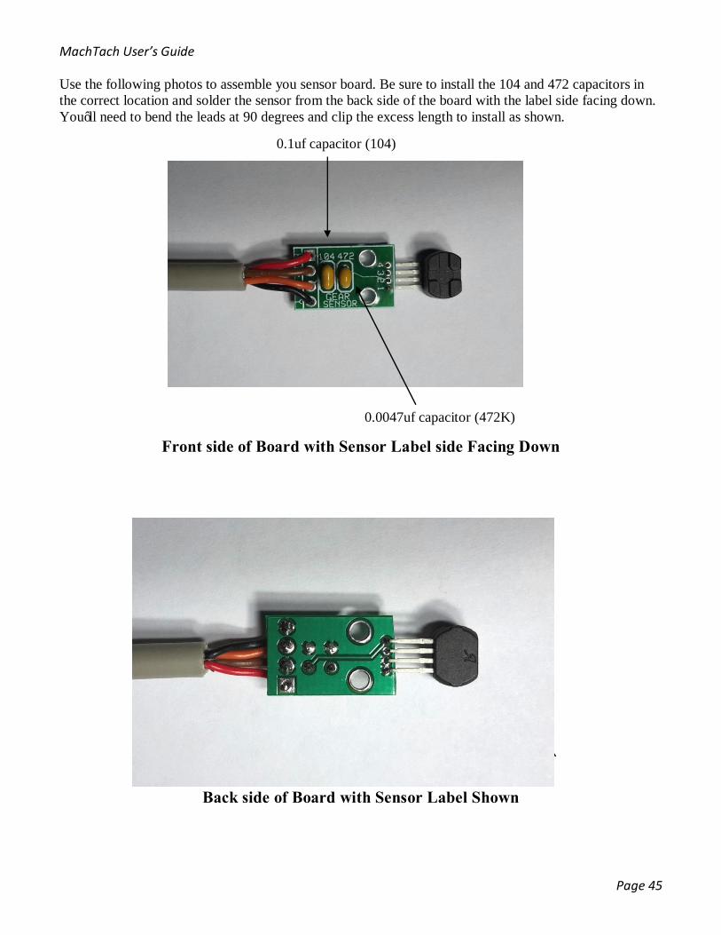
Use the following photos to assemble you sensor board. Be sure to install the 104 and 472 capacitors in the correct location and solder the sensor from the back side of the board with the label side facing down. You’ll need to bend the leads at 90 degrees and clip the excess length to install as shown.
Front side of Board with Sensor Label side Facing Down
Back side of Board with Sensor Label Shown
0.1uf capacitor (104)
0.0047uf capacitor (472K)
MachTach User’s Guide
Page 46
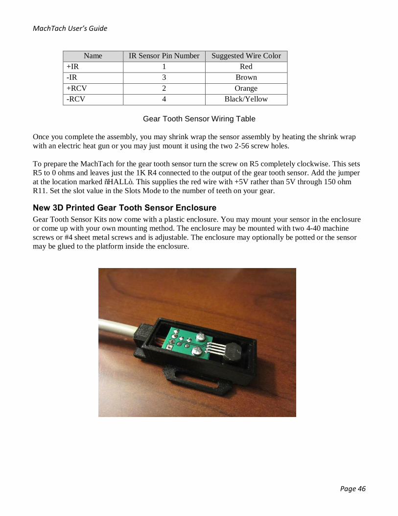
Name IR Sensor Pin Number Suggested Wire Color +IR 1 Red -IR 3 Brown +RCV 2 Orange -RCV 4 Black/Yellow
Gear Tooth Sensor Wiring Table
Once you complete the assembly, you may shrink wrap the sensor assembly by heating the shrink wrap with an electric heat gun or you may just mount it using the two 2-56 screw holes. To prepare the MachTach for the gear tooth sensor turn the screw on R5 completely clockwise. This sets R5 to 0 ohms and leaves just the 1K R4 connected to the output of the gear tooth sensor. Add the jumper at the location marked “HALL”. This supplies the red wire with +5V rather than 5V through 150 ohm R11. Set the slot value in the Slots Mode to the number of teeth on your gear.
New 3D Printed Gear Tooth Sensor Enclosure Gear Tooth Sensor Kits now come with a plastic enclosure. You may mount your sensor in the enclosure or come up with your own mounting method. The enclosure may be mounted with two 4-40 machine screws or #4 sheet metal screws and is adjustable. The enclosure may optionally be potted or the sensor may be glued to the platform inside the enclosure.
MachTach User’s Guide
Page 47
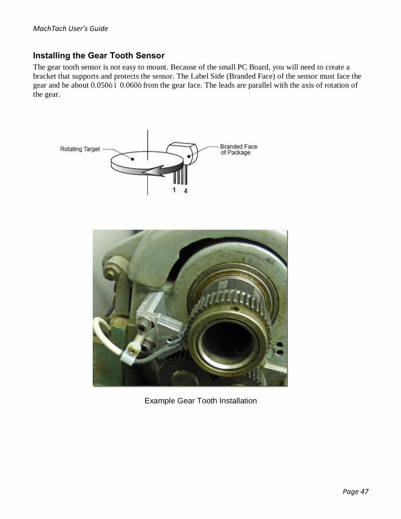
Installing the Gear Tooth Sensor The gear tooth sensor is not easy to mount. Because of the small PC Board, you will need to create a bracket that supports and protects the sensor. The Label Side (Branded Face) of the sensor must face the gear and be about 0.050” – 0.060” from the gear face. The leads are parallel with the axis of rotation of the gear.
Example Gear Tooth Installation
MachTach User’s Guide
Page 48
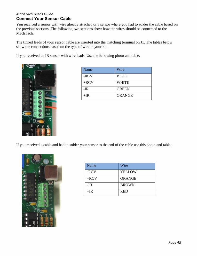
Connect Your Sensor Cable You received a sensor with wire already attached or a sensor where you had to solder the cable based on the previous sections. The following two sections show how the wires should be connected to the MachTach. The tinned leads of your sensor cable are inserted into the matching terminal on J1. The tables below show the connections based on the type of wire in your kit. If you received an IR sensor with wire leads. Use the following photo and table.
If you received a cable and had to solder your sensor to the end of the cable use this photo and table.
Name Wire
-RCV BLUE
+RCV WHITE
-IR GREEN
+IR ORANGE
Name Wire
-RCV YELLOW
+RCV ORANGE
-IR BROWN
+IR RED
MachTach User’s Guide
Page 49
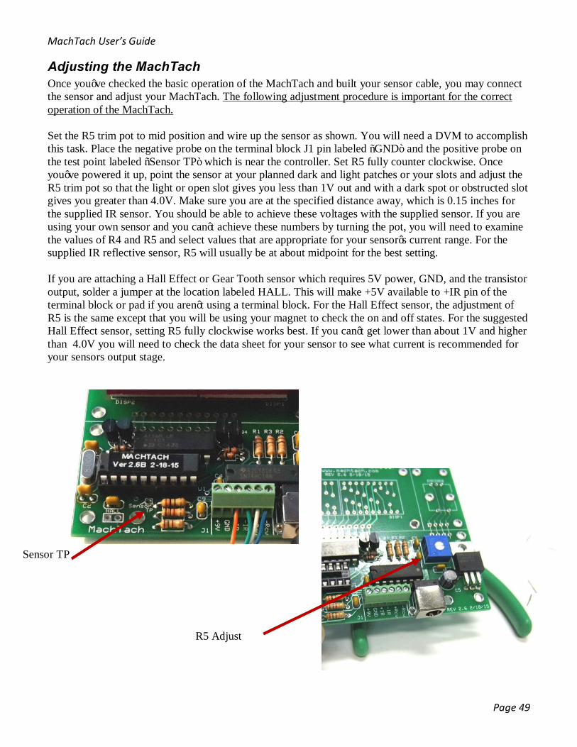
Adjusting the MachTach Once you’ve checked the basic operation of the MachTach and built your sensor cable, you may connect the sensor and adjust your MachTach. The following adjustment procedure is important for the correct operation of the MachTach. Set the R5 trim pot to mid position and wire up the sensor as shown. You will need a DVM to accomplish this task. Place the negative probe on the terminal block J1 pin labeled “GND” and the positive probe on the test point labeled “Sensor TP” which is near the controller. Set R5 fully counter clockwise. Once you’ve powered it up, point the sensor at your planned dark and light patches or your slots and adjust the R5 trim pot so that the light or open slot gives you less than 1V out and with a dark spot or obstructed slot gives you greater than 4.0V. Make sure you are at the specified distance away, which is 0.15 inches for the supplied IR sensor. You should be able to achieve these voltages with the supplied sensor. If you are using your own sensor and you can’t achieve these numbers by turning the pot, you will need to examine the values of R4 and R5 and select values that are appropriate for your sensor’s current range. For the supplied IR reflective sensor, R5 will usually be at about midpoint for the best setting. If you are attaching a Hall Effect or Gear Tooth sensor which requires 5V power, GND, and the transistor output, solder a jumper at the location labeled HALL. This will make +5V available to +IR pin of the terminal block or pad if you aren’t using a terminal block. For the Hall Effect sensor, the adjustment of R5 is the same except that you will be using your magnet to check the on and off states. For the suggested Hall Effect sensor, setting R5 fully clockwise works best. If you can’t get lower than about 1V and higher than 4.0V you will need to check the data sheet for your sensor to see what current is recommended for your sensors output stage.
Sensor TP
R5 Adjust
MachTach User’s Guide
Page 50
Installing the MachTach The MachTach can be installed inside of your machine tool or inside of the standard Serpac 31 plastic enclosure. This section will explain both types of installation.
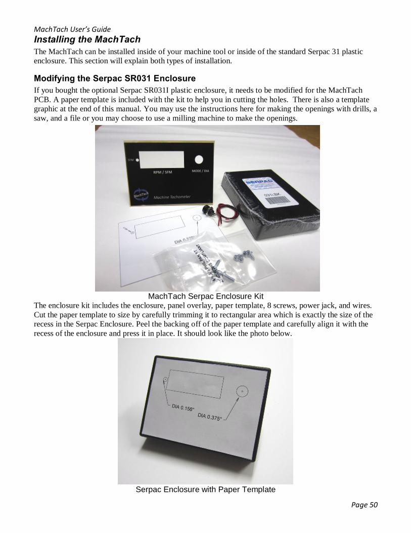
Modifying the Serpac SR031 Enclosure If you bought the optional Serpac SR031I plastic enclosure, it needs to be modified for the MachTach PCB. A paper template is included with the kit to help you in cutting the holes. There is also a template graphic at the end of this manual. You may use the instructions here for making the openings with drills, a saw, and a file or you may choose to use a milling machine to make the openings.
MachTach Serpac Enclosure Kit The enclosure kit includes the enclosure, panel overlay, paper template, 8 screws, power jack, and wires. Cut the paper template to size by carefully trimming it to rectangular area which is exactly the size of the recess in the Serpac Enclosure. Peel the backing off of the paper template and carefully align it with the recess of the enclosure and press it in place. It should look like the photo below.
Serpac Enclosure with Paper Template
MachTach User’s Guide
Page 51
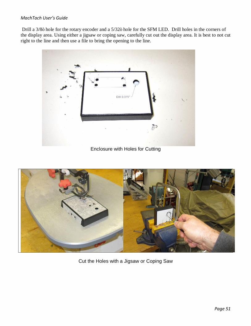
Drill a 3/8” hole for the rotary encoder and a 5/32” hole for the SFM LED. Drill holes in the corners of the display area. Using either a jigsaw or coping saw, carefully cut out the display area. It is best to not cut right to the line and then use a file to bring the opening to the line.
Enclosure with Holes for Cutting
Cut the Holes with a Jigsaw or Coping Saw

MachTach User’s Guide
Page 52
File the Display Hole to the Lines
Drill a ¼” holes in the right or left side of the enclosure for the sensor cable and a 9/32” hole for the power jack. You may instead drill these holes in the back cover if you make sure the power jack clears the board by placing it near the right or left edge. The hole for the power jack will need to be opened to 0.30”(7.6mm) using either a round file or a 19/64” drill. The power jack barrel is an odd size (0.030”).

MachTach User’s Guide
Page 53
Once you clean up the hole, you may hold the red plastic lens behind the hole and mark its size using a pencil. If you ordered a green kit, you should use the provided green Mylar. We provide the Mylar because the green plastic is too thick to fit between the enclosure and the LED displays. Apply the green Mylar to the display face not the panel overlay clear plastic.
Marking the size of the LED Lens
Remove the Paper Template in Preparation for the Panel Install
The red plastic lens should be cut to fit inside the Serpac display opening snuggly. The red plastic lens may be glued if you like or may simply be trapped between the panel and the display. For kits with green displays, a thin sheet of green Mylar is included. This green Mylar is self-sticking and should be applied to the LED displays not the plastic overlay. The green kits come with Mylar instead of acrylic because it is not possible to buy the translucent green acrylic thin enough to fit between the display and the top of the case.
MachTach User’s Guide
Page 54
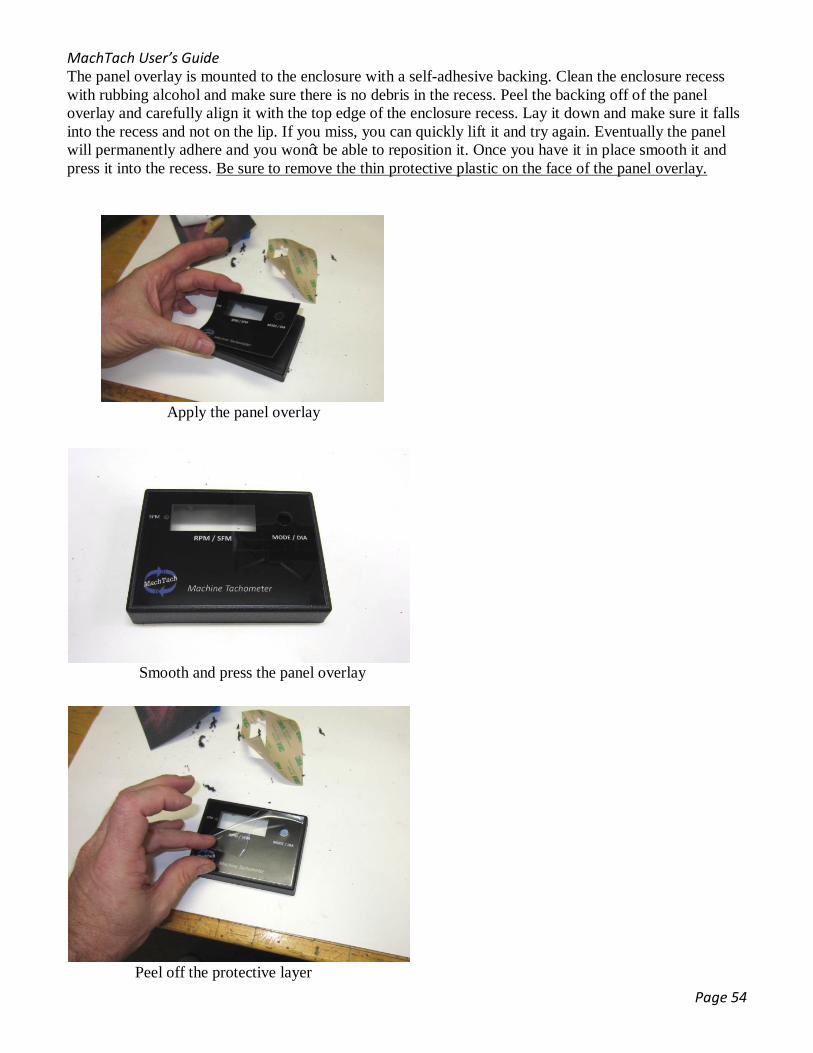
The panel overlay is mounted to the enclosure with a self-adhesive backing. Clean the enclosure recess with rubbing alcohol and make sure there is no debris in the recess. Peel the backing off of the panel overlay and carefully align it with the top edge of the enclosure recess. Lay it down and make sure it falls into the recess and not on the lip. If you miss, you can quickly lift it and try again. Eventually the panel will permanently adhere and you won’t be able to reposition it. Once you have it in place smooth it and press it into the recess. Be sure to remove the thin protective plastic on the face of the panel overlay.
Apply the panel overlay
Smooth and press the panel overlay
Peel off the protective layer
MachTach User’s Guide
Page 55
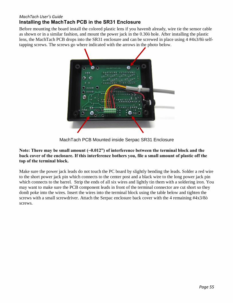
Installing the MachTach PCB in the SR31 Enclosure Before mounting the board install the colored plastic lens if you haven’t already, wire tie the sensor cable as shown or in a similar fashion, and mount the power jack in the 0.30” hole. After installing the plastic lens, the MachTach PCB drops into the SR31 enclosure and can be screwed in place using 4 #4x3/8” self-tapping screws. The screws go where indicated with the arrows in the photo below.
MachTach PCB Mounted inside Serpac SR31 Enclosure
Note: There may be small amount (~0.012”) of interference between the terminal block and the back cover of the enclosure. If this interference bothers you, file a small amount of plastic off the top of the terminal block. Make sure the power jack leads do not touch the PC board by slightly bending the leads. Solder a red wire to the short power jack pin which connects to the center post and a black wire to the long power jack pin which connects to the barrel. Strip the ends of all six wires and lightly tin them with a soldering iron. You may want to make sure the PCB component leads in front of the terminal connector are cut short so they don’t poke into the wires. Insert the wires into the terminal block using the table below and tighten the screws with a small screwdriver. Attach the Serpac enclosure back cover with the 4 remaining #4x3/8” screws.
MachTach User’s Guide
Page 56
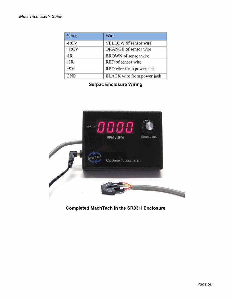
Serpac Enclosure Wiring
Completed MachTach in the SR031I Enclosure
Name Wire
-RCV YELLOW of sensor wire +RCV ORANGE of sensor wire -IR BROWN of sensor wire +IR RED of sensor wire +9V RED wire from power jack GND BLACK wire from power jack
MachTach User’s Guide
Page 57
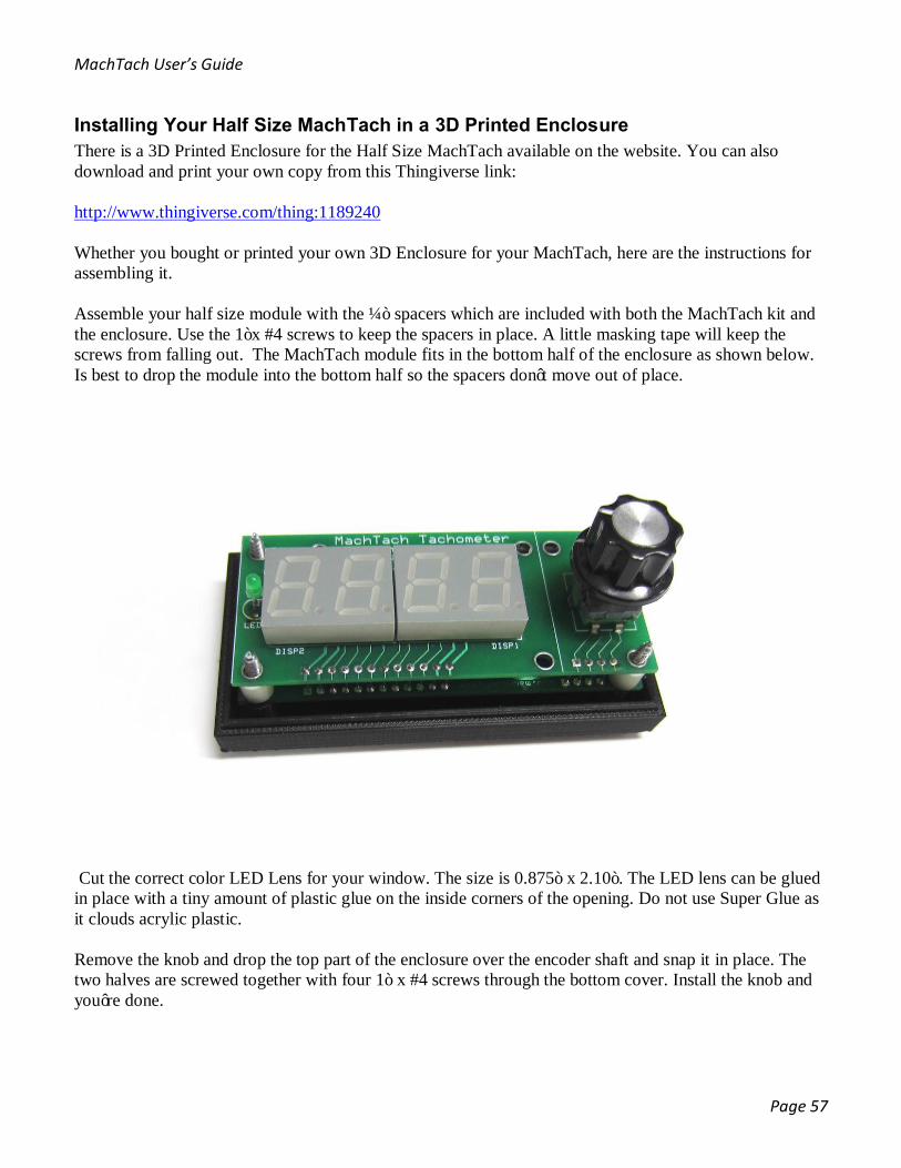
Installing Your Half Size MachTach in a 3D Printed Enclosure There is a 3D Printed Enclosure for the Half Size MachTach available on the website. You can also download and print your own copy from this Thingiverse link: http://www.thingiverse.com/thing:1189240 Whether you bought or printed your own 3D Enclosure for your MachTach, here are the instructions for assembling it. Assemble your half size module with the ¼” spacers which are included with both the MachTach kit and the enclosure. Use the 1”x #4 screws to keep the spacers in place. A little masking tape will keep the screws from falling out. The MachTach module fits in the bottom half of the enclosure as shown below. Is best to drop the module into the bottom half so the spacers don’t move out of place.
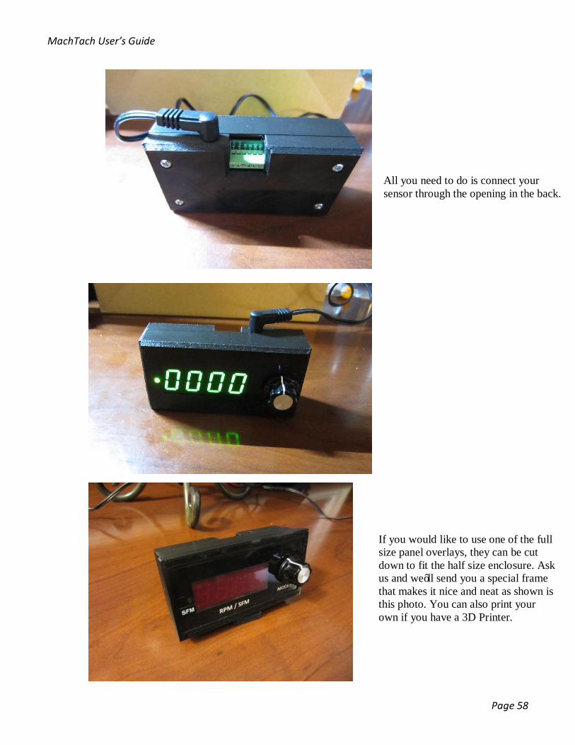
Cut the correct color LED Lens for your window. The size is 0.875” x 2.10”. The LED lens can be glued in place with a tiny amount of plastic glue on the inside corners of the opening. Do not use Super Glue as it clouds acrylic plastic. Remove the knob and drop the top part of the enclosure over the encoder shaft and snap it in place. The two halves are screwed together with four 1” x #4 screws through the bottom cover. Install the knob and you’re done.
MachTach User’s Guide
Page 58
If you would like to use one of the full size panel overlays, they can be cut down to fit the half size enclosure. Ask us and we’ll send you a special frame that makes it nice and neat as shown is this photo. You can also print your own if you have a 3D Printer.
All you need to do is connect your sensor through the opening in the back.

MachTach User’s Guide
Page 59
Installing the Full Size MachTach in Your Own Panel If you decide to install the MachTach in your own enclosure or panel, use the following diagram to drill the holes and make the display window. The display opening is 2.0” x 0.75”. Add the 0.125” mounting holes as shown. Add the 0.375” hole for the control and the 0.156” hole for the LED. Both of these holes are on the center line of the display.
Panel Layout Diagram (Full size MachTach)
The MachTach may be mounted on 0.3125” or 0.375” standoffs using 4-40 screws. The display will be clearer if you mount the included piece of translucent red/green plastic behind the opening. The red/green display plastic window can be attached to the back side of the panel with a little glue in the corners. You may also make the red plastic window flush by cutting it the same size as your panel opening and gluing it in place from the back. (Not shown) The standoffs can be as short as 0.3125” for a flush installation.
Display plastic can be installed inside opening or behind it.
MachTach User’s Guide
Page 60
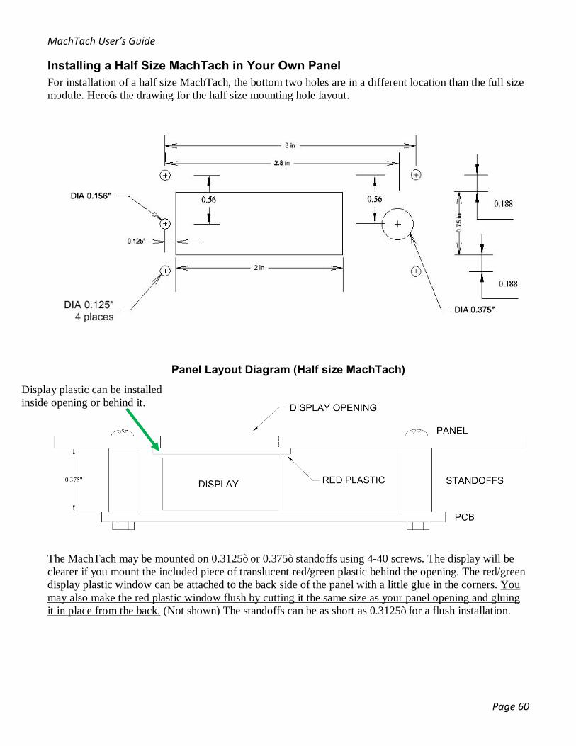
Installing a Half Size MachTach in Your Own Panel For installation of a half size MachTach, the bottom two holes are in a different location than the full size module. Here’s the drawing for the half size mounting hole layout.
Panel Layout Diagram (Half size MachTach)
The MachTach may be mounted on 0.3125” or 0.375” standoffs using 4-40 screws. The display will be clearer if you mount the included piece of translucent red/green plastic behind the opening. The red/green display plastic window can be attached to the back side of the panel with a little glue in the corners. You may also make the red plastic window flush by cutting it the same size as your panel opening and gluing it in place from the back. (Not shown) The standoffs can be as short as 0.3125” for a flush installation.
Display plastic can be installed inside opening or behind it.
MachTach User’s Guide
Page 61
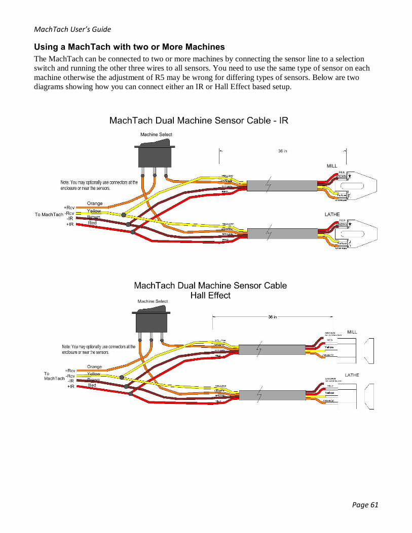
Using a MachTach with two or More Machines The MachTach can be connected to two or more machines by connecting the sensor line to a selection switch and running the other three wires to all sensors. You need to use the same type of sensor on each machine otherwise the adjustment of R5 may be wrong for differing types of sensors. Below are two diagrams showing how you can connect either an IR or Hall Effect based setup.
MachTach User’s Guide
Page 62
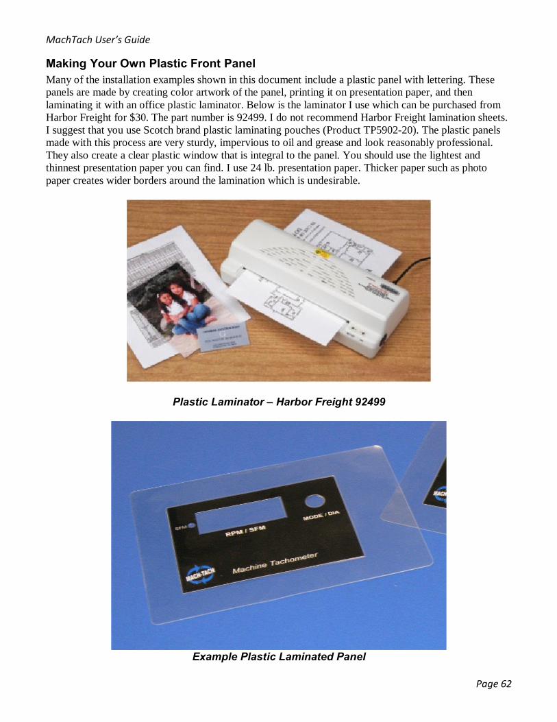
Making Your Own Plastic Front Panel Many of the installation examples shown in this document include a plastic panel with lettering. These panels are made by creating color artwork of the panel, printing it on presentation paper, and then laminating it with an office plastic laminator. Below is the laminator I use which can be purchased from Harbor Freight for $30. The part number is 92499. I do not recommend Harbor Freight lamination sheets. I suggest that you use Scotch brand plastic laminating pouches (Product TP5902-20). The plastic panels made with this process are very sturdy, impervious to oil and grease and look reasonably professional. They also create a clear plastic window that is integral to the panel. You should use the lightest and thinnest presentation paper you can find. I use 24 lb. presentation paper. Thicker paper such as photo paper creates wider borders around the lamination which is undesirable.
Plastic Laminator – Harbor Freight 92499
Example Plastic Laminated Panel
MachTach User’s Guide
Page 63
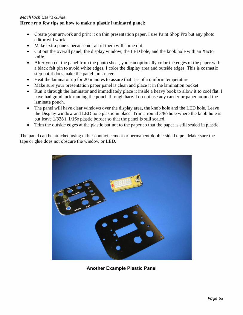
Here are a few tips on how to make a plastic laminated panel:
• Create your artwork and print it on thin presentation paper. I use Paint Shop Pro but any photo editor will work.
• Make extra panels because not all of them will come out • Cut out the overall panel, the display window, the LED hole, and the knob hole with an Xacto
knife. • After you cut the panel from the photo sheet, you can optionally color the edges of the paper with
a black felt pin to avoid white edges. I color the display area and outside edges. This is cosmetic step but it does make the panel look nicer.
• Heat the laminator up for 20 minutes to assure that it is of a uniform temperature • Make sure your presentation paper panel is clean and place it in the lamination pocket • Run it through the laminator and immediately place it inside a heavy book to allow it to cool flat. I
have had good luck running the pouch through bare. I do not use any carrier or paper around the laminate pouch.
• The panel will have clear windows over the display area, the knob hole and the LED hole. Leave the Display window and LED hole plastic in place. Trim a round 3/8” hole where the knob hole is but leave 1/32” – 1/16” plastic border so that the panel is still sealed.
• Trim the outside edges at the plastic but not to the paper so that the paper is still sealed in plastic.
The panel can be attached using either contact cement or permanent double sided tape. Make sure the tape or glue does not obscure the window or LED.
Another Example Plastic Panel
MachTach User’s Guide
Page 64
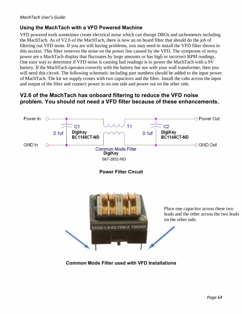
Using the MachTach with a VFD Powered Machine VFD powered tools sometimes create electrical noise which can disrupt DROs and tachometers including the MachTach. As of V2.6 of the MachTach, there is now an on board filter that should do the job of filtering out VFD noise. If you are still having problems, you may need to install the VFD filter shown in this section. This filter removes the noise on the power line caused by the VFD. The symptoms of noisy power are a MachTach display that fluctuates by large amounts or has high or incorrect RPM readings. One easy way to determine if VFD noise is causing bad readings is to power the MachTach with a 9V battery. If the MachTach operates correctly with the battery but not with your wall transformer, then you will need this circuit. The following schematic including part numbers should be added to the input power of MachTach. The kit we supply comes with two capacitors and the filter. Install the cabs across the input and output of the filter and connect power in on one side and power out on the other side. V2.6 of the MachTach has onboard filtering to reduce the VFD noise problem. You should not need a VFD filter because of these enhancements.
Power Filter Circuit
Common Mode Filter used with VFD Installations
587-2831-ND
Place one capacitor across these two leads and the other across the two leads on the other side.
MachTach User’s Guide
Page 65
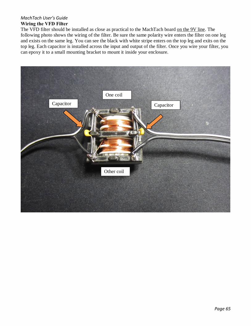
Wiring the VFD Filter The VFD filter should be installed as close as practical to the MachTach board on the 9V line. The following photo shows the wiring of the filter. Be sure the same polarity wire enters the filter on one leg and exists on the same leg. You can see the black with white stripe enters on the top leg and exits on the top leg. Each capacitor is installed across the input and output of the filter. Once you wire your filter, you can epoxy it to a small mounting bracket to mount it inside your enclosure.
Capacitor Capacitor
One coil
Other coil

MachTach User’s Guide
Page 66
Troubleshooting If you find that after assembling the MachTach, that it does not work, here are some tips to get it going. Most MachTach Problems are caused by a missed or cold solder joint or a bad or miss wired cable. Erratic operation is usually caused by a misadjusted sensor or noise from a VFD or other source. No Display Recheck all of your soldering. It is easy to miss soldering a joint or to have a cold joint. Check that you have 7-9V coming into the board in the lower right corner. Check that 5V appears at pin 1 of the MachTach IC as referenced to the GND pin in the lower right corner. I you assembled a half size kit; make sure you connected the 16 jumpers between the two boards. Nothing happens when you push the knob or turn it If you have built a half size module, make sure you connected the 4 jumpers near the encoder. Check that 5V appears at pin 14 of U3. Make sure that R1, R2, R3 have 5V on one pin. With a DVM connected to GND at the lower right corner and pins 9 and 11 of U3, make sure that as you turn the knob you see the voltage switching from approximately zero to 5V. Do the same at pins 8 and 10 of U3. With a DVM connected to GND at the lower right corner and pins 13 of U3, make sure that as you push the knob you see the voltage switching from approximately zero to 5V. Do the same at pin 12 of U3. Display reads all zeroes but no RPM Recheck your sensor wiring. This is an easy place to make a mistake. Check that 5V appears at pin 14 of U3. With a DVM at Sensor TP, turn your machine to activate the sensor slowly. Do this by hand if possible. Make sure that Sensor TP is switching between less than 1 V and greater than 4 V. If you find this is OK, check for the same at pins 2, 4, and 6 of U3. Check for switching between less than 1 V and greater than 4 V at pin 17 of the MachTach IC (pin 17) Erratic Operation If your RPM display is erratic, check the distance of the sensor. Check the wiring of the cable. Try operating the MachTach with a 9V battery. If it works normally, your power has noise possibly from a VFD or other noise in your shop environment. Install a common mode filter described in an earlier section. Also make sure your sensor cable does not run close to the motor wiring. This can also cause erratic results. Wrong RPM Recheck that you have entered the correct number of slots/patches/magnets. Try running from a 9V battery. If it works correctly, add the filter described earlier in this manual. Make sure your sensor is the correct distance from the target. If you are reading double the expected RPM with a Hall Effect sensor, you have installed your magnets backwards. Hall Effect sensors can see double the number of flux changes when the magnets are installed backwards and are close together. The SFM LED is Always On It is installed backwards. Remove it and solder it in the other direction. Some of the Display LEDs do not Light Check your solder connections. If only one display digit is affected, the bad connection is with the transistor driving that digit. If the same segment is out on all four displays, the bad connection is between the MachTach, RN1, and the displays. If you have a half size module, recheck your jumper connections between the boards.

MachTach User’s Guide
Page 67
Half Size Module Display or Knob Does Not Work Make sure that all 16 of the jumpers are installed and making good connections. Sometime users forget the 4 jumpers near the rotary encoder. The RPM Reading is Erratic An erratic display can be caused by unevenly spaced reflective patches or unevenly spaced magnets or slots. Do you have a VFD? You may need the VFD filter. The RPM is wrong but steady Check that you did not mix up the 22pf capacitors with the 0.1uf capacitors. It is easy to mix up the 4700pf cap with the 22pf caps. They are the same size. Did you enter the correct number of patches/slots/magnets during the setup? If using Hall Effect sensor, are your magnets facing the correct direction? The wrong direction can cause a double reading under certain circumstances. MachTach works but Sensor has no Effect Check that you used the correct diagram depending on whether you mounted the connector on the front or backside of the board (V2.3,2.4,2.5). Recheck your wiring. For IR sensors waving a white sheet of plastic close to the window should give you a display reading. For Hall Effect sensors, moving the North end of the magnet across the face of the sensor should give a reading on the display. For Problems with Hall Effect Sensors Check that you installed the Hall jumper. Make sure that R5 was adjusted. Usually all the way clockwise is correct for the Hall sensors we sell. Check the magnet orientation. It only works with the North Pole facing the sensor’s chamfered face. The wrong direction can cause a double reading under certain circumstances. The RPM reading is Double the value it should be (600 RPM instead of 300 RPM). This can be caused by the wrong capacitors being used for C1 and C2. Or by there being solder shorts in this area. If you are using a Hall Effect sensor, you may have installed your magnets in the wrong direction. The RPM Reading is Double but You are Not Using the Hall Effect Sensor. Check for solder bridges around crystal X1 or for wrong values of C1 and C2. There have been a few cases of either the wrong value of C1/C2 or a solder bridge giving an RPM reaing that is double the normal value. No RPM Reading But MachTach Works OK. Recheck the sensor distance and that you can get both 0V and 5 V at the sensor TP when moving your targets. Recheck your soldering. Most of the time when there is a problem, it is caused by a missing or bad solder joint.
MachTach User’s Guide
Page 68
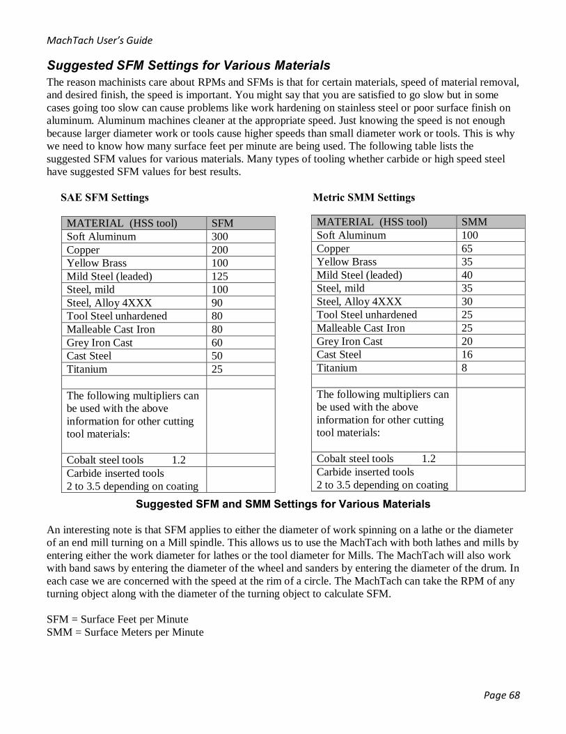
Suggested SFM Settings for Various Materials The reason machinists care about RPMs and SFMs is that for certain materials, speed of material removal, and desired finish, the speed is important. You might say that you are satisfied to go slow but in some cases going too slow can cause problems like work hardening on stainless steel or poor surface finish on aluminum. Aluminum machines cleaner at the appropriate speed. Just knowing the speed is not enough because larger diameter work or tools cause higher speeds than small diameter work or tools. This is why we need to know how many surface feet per minute are being used. The following table lists the suggested SFM values for various materials. Many types of tooling whether carbide or high speed steel have suggested SFM values for best results. SAE SFM Settings Metric SMM Settings
Suggested SFM and SMM Settings for Various Materials An interesting note is that SFM applies to either the diameter of work spinning on a lathe or the diameter of an end mill turning on a Mill spindle. This allows us to use the MachTach with both lathes and mills by entering either the work diameter for lathes or the tool diameter for Mills. The MachTach will also work with band saws by entering the diameter of the wheel and sanders by entering the diameter of the drum. In each case we are concerned with the speed at the rim of a circle. The MachTach can take the RPM of any turning object along with the diameter of the turning object to calculate SFM. SFM = Surface Feet per Minute SMM = Surface Meters per Minute
MATERIAL (HSS tool) SFM Soft Aluminum 300 Copper 200 Yellow Brass 100 Mild Steel (leaded) 125 Steel, mild 100 Steel, Alloy 4XXX 90 Tool Steel unhardened 80 Malleable Cast Iron 80 Grey Iron Cast 60 Cast Steel 50 Titanium 25 The following multipliers can be used with the above information for other cutting tool materials:
Cobalt steel tools 1.2 Carbide inserted tools 2 to 3.5 depending on coating
MATERIAL (HSS tool) SMM Soft Aluminum 100 Copper 65 Yellow Brass 35 Mild Steel (leaded) 40 Steel, mild 35 Steel, Alloy 4XXX 30 Tool Steel unhardened 25 Malleable Cast Iron 25 Grey Iron Cast 20 Cast Steel 16 Titanium 8 The following multipliers can be used with the above information for other cutting tool materials:
Cobalt steel tools 1.2 Carbide inserted tools 2 to 3.5 depending on coating
MachTach User’s Guide
Page 69
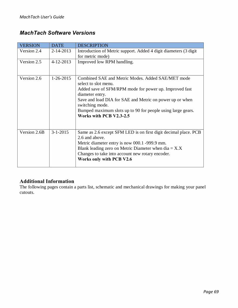
MachTach Software Versions VERSION DATE DESCRIPTION Version 2.4 2-14-2013 Introduction of Metric support. Added 4 digit diameters (3 digit
for metric mode) Version 2.5 4-12-2013 Improved low RPM handling.
Version 2.6 1-26-2015
Combined SAE and Metric Modes. Added SAE/MET mode select to slot menu. Added save of SFM/RPM mode for power up. Improved fast diameter entry. Save and load DIA for SAE and Metric on power up or when switching mode. Bumped maximum slots up to 90 for people using large gears. Works with PCB V2.3-2.5
Version 2.6B 3-1-2015 Same as 2.6 except SFM LED is on first digit decimal place. PCB
2.6 and above. Metric diameter entry is now 000.1 -999.9 mm. Blank leading zero on Metric Diameter when dia = X.X Changes to take into account new rotary encoder. Works only with PCB V2.6
Additional Information The following pages contain a parts list, schematic and mechanical drawings for making your panel cutouts.
MachTach User’s Guide
Page 70
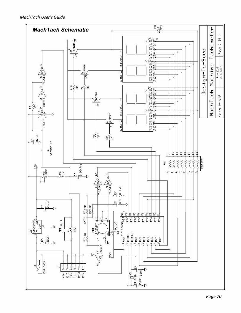
MachTach Schematic
MachTach User’s Guide
Page 71
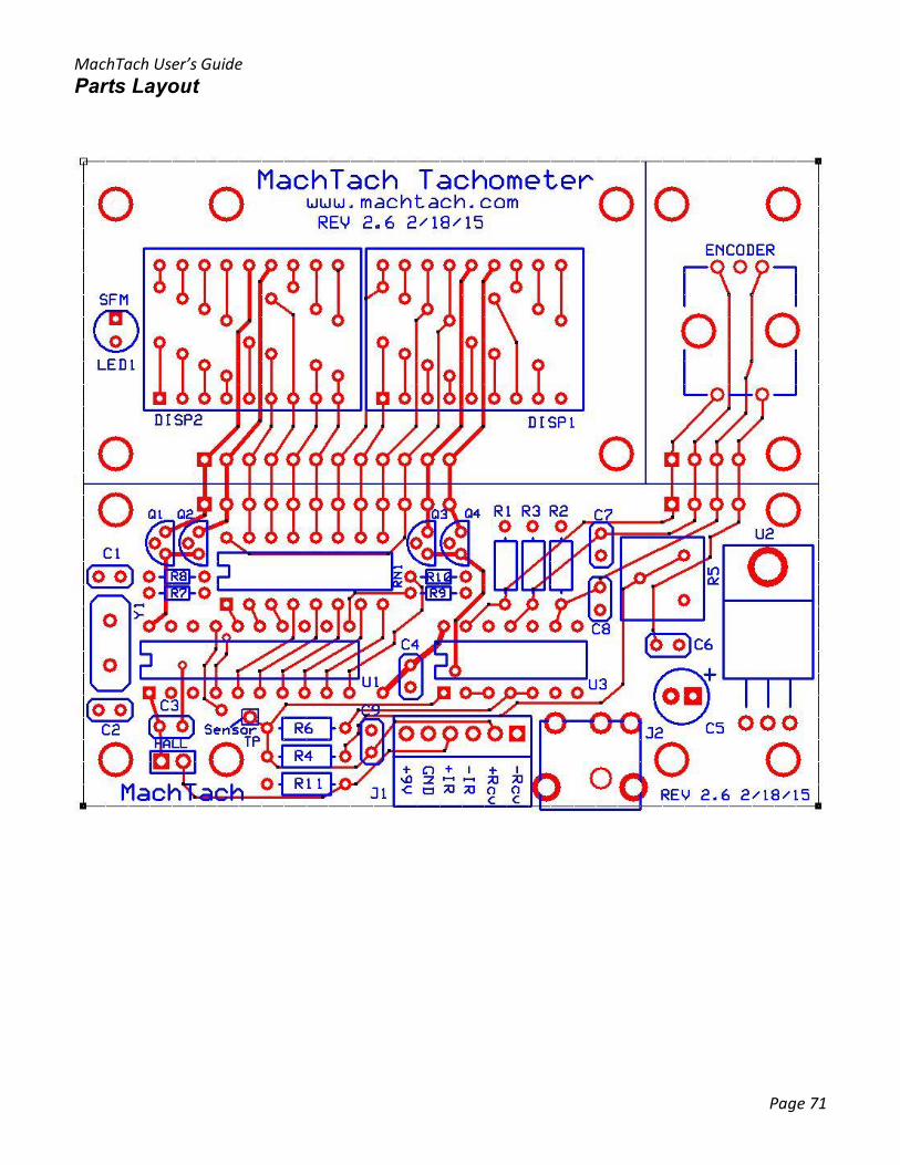
Parts Layout

MachTach User’s Guide
Page 72

MachTach User’s Guide
Page 73
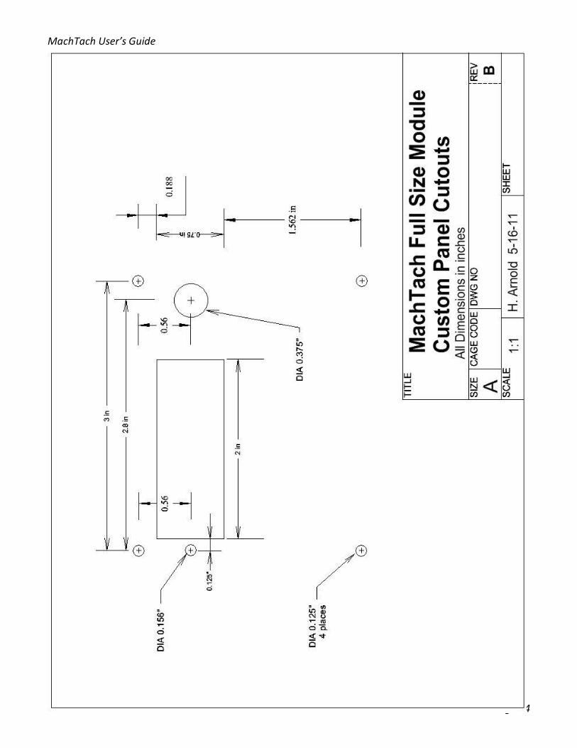
MachTach User’s Guide
Page 74

MachTach User’s Guide
Page 75

MachTach User’s Guide
Page 76
Frequently Asked Questions 1. Why does the MachTach only go to 9999 RPMs? - The MachTach is designed for machine tools which rarely run faster than a few thousand RPMs so it did not make sense to add another display for 10,0000 RPM capability 2. Can I mount the MachTach inside my machine tool? - Yes! The MachTach is designed to be small enough to fit into many machine tool panels. The MachTach can be assembled into a half size module which will fit into tight spaces. 3. What types of sensors are supported? - The MachTach will work with IR reflective, IR interruptive, Hall Effect, Gear Tooth Sensors, and any other sensor with an output of at least a 1V - 4V waveform will work. 4. Why would I need the VFD Filter? Sometimes machines that have a VFD or other frequency drive motor controller create a noisy electrical environment. This is similar to static on a radio when a power tool is operated but is conducted through the power wiring. The filter removes the noise so that the MachTach can operate correctly. The noise can cause erratic MachTach operation. You should not need an external filter as of V2.6 of the MachTach. 5. What happens if I can't get my MachTach to work after assembling it? – We’ll help you to get it working. Send us your symptoms in an email. MachTach also has a great forum with people that have built MachTachs where you can ask questions. Send us photos of the front and back side of your board and we’ll look to see what may be wrong. Worst case, you can send your MachTach back to us and we'll fix it for a nominal fee. 6. Why is Surface Feet per Minute SFM important? - RPM is only one way of telling how fast something is going and it does not take into account the diameter of the tool or the work piece that is turning. Surface Feet per Minute measures how fast the material is moving past the tool whether it is an end mill or a lathe tool. SFM is important in controlling finish for materials like aluminum and stainless steel and for protecting your tooling from excessive speeds or your work piece from too slow of a speed. More MachTach information and applications can be found at the following two websites: www.machtach.com http://groups.yahoo.com/group/MachTach/