Embed Size (px)
Citation preview
User Requirement Specification for EVF [Informasjon]
Kategori: [Styrende dokumenter] Dok-ID: [URS-xxx] Organisatorisk plassering: [ ] Forfattere:
[Kimberley Joanne Hatfield,]
Versjon: [1] Dato: [27092018]
Dok. eier: [Signatur] Dok. ansvarlig: [Einar K.
Kristoffersen]
Gyldig til: [GyldigTil]
Side 1 av 42
User Requirement Specification
Ex vivo Facility (EVF) for Stem Cell Treatment, Cellular
Therapy and Regenerative Medicine
Bergen Stem Cell and Regenerative Medicine Facility
Haukeland University Hospital
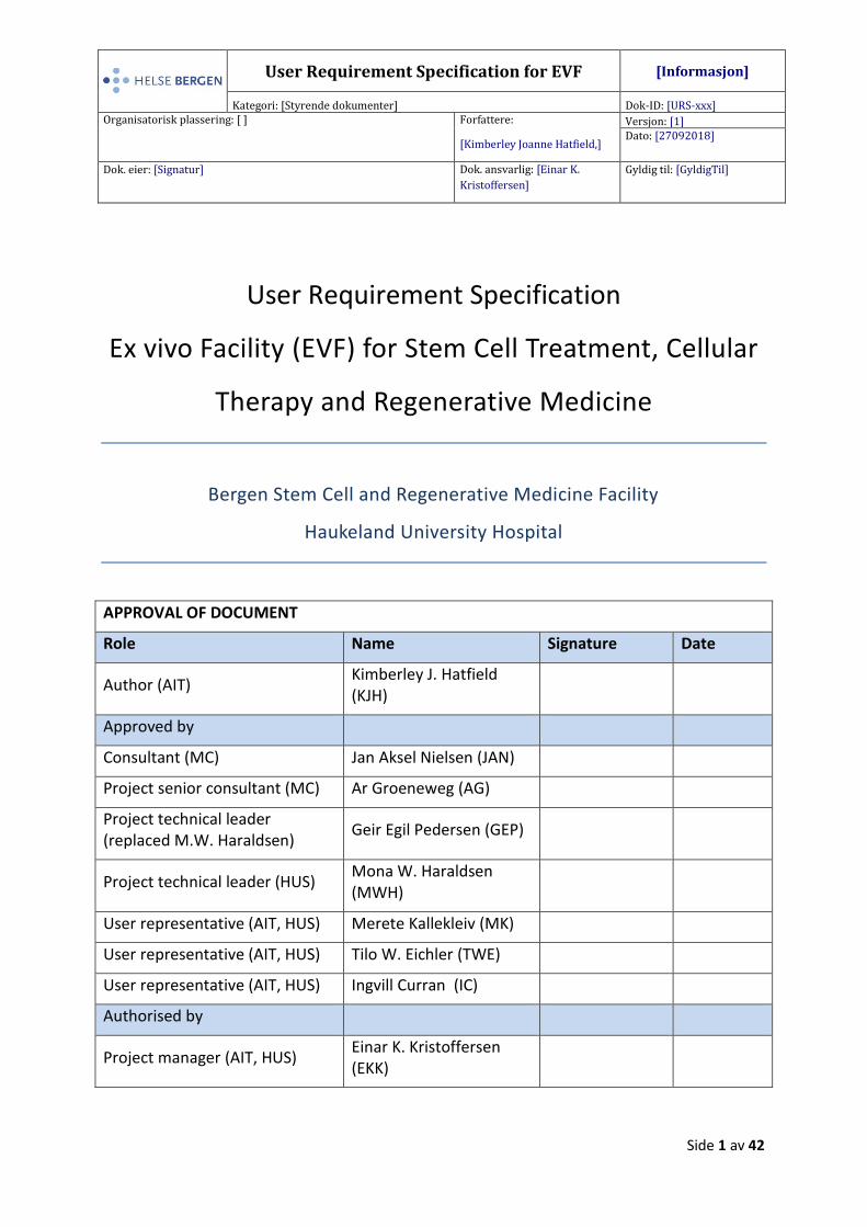
APPROVAL OF DOCUMENT
Role Name Signature Date
Author (AIT) Kimberley J. Hatfield (KJH)
Approved by
Consultant (MC) Jan Aksel Nielsen (JAN)
Project senior consultant (MC) Ar Groeneweg (AG)
Project technical leader (replaced M.W. Haraldsen)
Geir Egil Pedersen (GEP)
Project technical leader (HUS) Mona W. Haraldsen (MWH)
User representative (AIT, HUS) Merete Kallekleiv (MK)
User representative (AIT, HUS) Tilo W. Eichler (TWE)
User representative (AIT, HUS) Ingvill Curran (IC)
Authorised by
Project manager (AIT, HUS) Einar K. Kristoffersen (EKK)
User Requirement Specification for GMP facility Dok-ID: [ID]
Versjon: [Ver] Dato: [GjelderFra]
Side 2 av 42
1 Publication record
All changes to this document are recorded in the Publication Record Table.
PUBLICATION RECORD
Version Change description Initials Section Date
(d/m/y)
01 New document KJH 27.09.2018
User Requirement Specification for GMP facility Dok-ID: [ID]
Versjon: [Ver] Dato: [GjelderFra]
Side 3 av 42
Content 1 Publication record ........................................................................................................................... 2
2 Abbreviations and Supporting figures ............................................................................................. 6
3 Purpose of URS ................................................................................................................................ 8
3.1 Deviations ................................................................................................................................ 8
3.2 Conflicting requirements ......................................................................................................... 8
3.3 Design responsibility ............................................................................................................... 8
3.4 Code compliance ..................................................................................................................... 8
3.5 Units ........................................................................................................................................ 8
4 General overview ............................................................................................................................ 9
4.1 Purpose of the EVF .................................................................................................................. 9
4.2 Scope ....................................................................................................................................... 9
4.3 Site location ............................................................................................................................. 9
4.4 Type of products .................................................................................................................... 10
5 Space and layout requirements .................................................................................................... 10
5.1 Design strategy and layout .................................................................................................... 10
5.2 Description of layout ............................................................................................................. 11
5.3 Flow in the facility ................................................................................................................. 13
5.3.1 Personnel flow ............................................................................................................... 13
5.3.2 Starting material and (intermediate/final) product flow .............................................. 13
5.3.3 Ancillary material flow ................................................................................................... 14
5.3.4 Waste flow ..................................................................................................................... 14
5.3.5 Gowning rooms and material airlocks ........................................................................... 15
6 Operational requirements ............................................................................................................. 15
6.1 Operation time ...................................................................................................................... 15
6.2 Access control ........................................................................................................................ 15
6.3 Microbiological monitoring ................................................................................................... 16
7 External additional supporting facilities ........................................................................................ 16
8 Central monitoring system ............................................................................................................ 16
9 Lighting and acoustics ................................................................................................................... 17
9.1 Lighting .................................................................................................................................. 17
9.2 Acoustics ................................................................................................................................ 17
10 Utilities .......................................................................................................................................... 18
User Requirement Specification for GMP facility Dok-ID: [ID]
Versjon: [Ver] Dato: [GjelderFra]
Side 4 av 42
10.1 Water ..................................................................................................................................... 18
10.2 Process gases ......................................................................................................................... 18
10.3 Liquid nitrogen ...................................................................................................................... 19
11 HVAC requirements ....................................................................................................................... 19
11.1 Air changes ............................................................................................................................ 19
11.2 Air flow .................................................................................................................................. 20
11.3 HEPA filters and other filters ................................................................................................. 20
11.4 Relative humidity ................................................................................................................... 20
11.5 Temperature .......................................................................................................................... 20
11.6 Air tightness ........................................................................................................................... 21
11.7 Pressure and zoning .............................................................................................................. 21
12 Electrical system ............................................................................................................................ 23
12.1 Interlocking system ............................................................................................................... 23
13 Permanent furnishing and equipment .......................................................................................... 24
13.1 Biological safety cabinets and MALs ..................................................................................... 24
13.2 Communication system ......................................................................................................... 25
13.3 Computer system .................................................................................................................. 25
14 Cleaning and sanitizing agents ...................................................................................................... 25
15 Methods of construction ............................................................................................................... 26
15.1 Interior finishes and materials .............................................................................................. 26
15.2 Doors ..................................................................................................................................... 27
16 Regulatory Requirements .............................................................................................................. 27
16.1 GMP and relevant guidelines ................................................................................................ 28
16.2 International standards and codes ........................................................................................ 28
16.3 Norwegian regulatory requirements ..................................................................................... 29
17 Documentation .............................................................................................................................. 29
18 Commissioning .............................................................................................................................. 30
19 Qualification and validation .......................................................................................................... 30
19.1 Validation elements............................................................................................................... 31
19.2 Factory acceptance test ........................................................................................................ 32
19.3 Site acceptance test .............................................................................................................. 32
19.4 Acceptance criteria ................................................................................................................ 32
19.5 Handover to end-users .......................................................................................................... 33
User Requirement Specification for GMP facility Dok-ID: [ID]
Versjon: [Ver] Dato: [GjelderFra]
Side 5 av 42
19.6 EVF in ordinary use ................................................................................................................ 33
20 Life cycle and revalidation ............................................................................................................. 33
21 Appendix ........................................................................................................................................ 34
User Requirement Specification for GMP facility Dok-ID: [ID]
Versjon: [Ver] Dato: [GjelderFra]
Side 6 av 42
2 Abbreviations and Supporting figures
Table 1. List of Abbreviations
AIT Department of immunology and transfusion medicine
AHU Air handling unit
BSC Biological Safety Cabinet
C Commissioning
CAV Constant Air Volume
EurPharm European Pharmacopoeia
EVF Ex vivo facility
FAT Factory Acceptance Test
GEP Good Engineering Practice
GMP Good manufacturing practice
HEPA High Efficiency Particulate Air
HSE Health, Safety and Environment
HUS Haukeland University Hospital
HVAC Heating, Ventilation and Air Conditioning
IQ Installation Qualification
JACIE Joint accreditation committee ISCT EMBT
LAF Laminar Air Flow
LK Laboratory Clinic
MAL Material Air Lock (= pass box)
MC Multiconsult
NA Not Applicable
PB Passbox (= MAL)
PQ Performance qualification
PV Performance validation
Q Qualification
QA Quality assurance
QC Quality control
QM Quality management
QMS Quality management system
User Requirement Specification for GMP facility Dok-ID: [ID]
Versjon: [Ver] Dato: [GjelderFra]
Side 7 av 42
QP Qualified Person
RFQ Request for Quotation
SAT Site Acceptance Test
SOP Standard operating procedure
URS User Requirement Specification
VAV Variable Air Volume
VMP Validation master plan (this document)
VP Validation plan
VSR Validation Summary Report
Table 2. List of supporting Figures/Tables in Appendix
Appendix A1 Layout drawing of EVF
Appendix A2 Personnel flow diagram
Appendix A3 Starting material flow diagram
Appendix A4 Product flow diagram
Appendix A5 Ancillary material flow diagram
Appendix A6 Waste flow diagram
Appendix A7 Differential pressure cascade
Appendix A8 List of permanent equipment
Appendix A9 Validation and project life cycle
Additional supporting figures, tables and diagrams can be found in 129995-TVF-Beskrivelse and VMP
for EVF.
User Requirement Specification for GMP facility Dok-ID: [ID]
Versjon: [Ver] Dato: [GjelderFra]
Side 8 av 42
3 Purpose of URS This User Requirement Specification (URS) intends to provide the requirements for the Ex Vivo
Facility (EVF) at Haukeland University Hospital (HUS) in Bergen, with regard to design, construction,
ventilation, utilities and permanent installations in order to manufacture medicinal products in
accordance to national authority regulations and EU-GMP guidelines. This URS along with the layout
drawing provides the elements of the conceptual design.
This URS as part of the Request for Quotation (RFQ) provides bidders with the necessary guidance to
design the Ex Vivo Facility and to achieve mandatory compliance. At the same time, the goal is not to
stifle innovation from the design team and Vendor seeking to provide an optimal solution to meet
the client’s operational objectives and regulatory compliance.
3.1 Deviations
Deviations from the requirements of this specification may only be applied after obtaining a written
approval from the Purchaser.
3.2 Conflicting requirements
All conflicts between the requirements of this URS, codes, standards, purchase order and drawings
shall be brought to the project engineers’ attention for clarification before proceeding with the
design, manufacture or procurement of the relevant part.
3.3 Design responsibility
Nothing contained in this specification, purchase order, drawings etc. shall relieve the Vendor of his
responsibility for constructing the facility to meet the specified conditions.
3.4 Code compliance
It shall be the Vendor's responsibility to determine and comply with the requirements of applicable
mandatory rules (i.e. city, national, codes or ordinances). The costs of the required inspections to
comply with code(s) or governmental rules and regulations shall be included in the proposal.
3.5 Units
All measurements and units used in design, fabrication and documents shall be in SI units. An
exception may be pressure in bar(a) or bar(g).
User Requirement Specification for GMP facility Dok-ID: [ID]
Versjon: [Ver] Dato: [GjelderFra]
Side 9 av 42
4 General overview
4.1 Purpose of the EVF
The construction of the ex-vivo facility is supported by funding from the Helse Vest Foundation and
was initiated based on two evolving demands. Firstly, this facility aims to meet the interests of the
scientific community in need of a GMP compliant clean room facility to manufacture advanced
therapy medicinal products (ATMPs) for phase I and phase II clinical studies. Secondly, the facility will
include a dedicated clean room area for minimal manipulation of human cells, an activity which is
currently being conducted by the Department of immunology and transfusion medicine (AIT), but
new facilities are needed to meet the requirements of the Norwegian regulations for processing
human cells and tissues (FOR-2016-09-07-1052).
The facility will have a pharmaceutical quality management system (QMS) in line with GMP
guidelines, and the entire facility should be built and run according to EU-GMP guidelines and
Norwegian regulations, and will be subjected to inspection (and approved) by the Norwegian
Medicinal Agency. Areas and activities where minimal manipulation is conducted will be under the
inspection of the Norwegian Board of Health Supervision (Statens helsetilsyn).
4.2 Scope
This URS describes specifications for the GMP-compliant clean rooms that are part of the so-called
EVF, to be established in the Laboratory Building, floor 1M for manufacturing and/or manipulation of
human cells, including supporting clean room corridors/transition spaces, a sluice system for
appropriate gowning and material airlocks (MALs) for transfer between classification levels. The URS
also includes specifications for quality control areas and storage areas for ancillary material and
biological material.
4.3 Site location
The EVF will be located on the 1M floor of the Laboratory Building at Haukeland University Hospital.
This mezzanine constitutes around 262 m2 and will have a ceiling height of 2.40m (roof total height
3.24m). There is not sufficient space for a ventilation system above the roof of the facility, so the
User Requirement Specification for GMP facility Dok-ID: [ID]
Versjon: [Ver] Dato: [GjelderFra]
Side 10 av 42
ventilation system and main technical area, including the computer server/IT system, will be situated
on floor 1 directly beneath the facility.
4.4 Type of products
The facility will primarily manufacture ATMPs according to Annex 1; Manufacture of Sterile Medicinal
Products (as found in Directive 2001/83/EC, amended by Regulation EC 1394/2007), including tissue
engineered products and somatic cell therapy medicinal products for use in clinical trials. Future
production may also include combined ATMPs where human cells are embedded in a biodegradable
matrix or scaffold. Human blood and blood products, as well as (extra)cellular- and tissue-based
materials, may also be processed. In addition to ATMPs, minimal manipulation of human cells
(routine preparation of stem cell products) will be conducted according to Tissue and Cells Directive
2004/23/EC. Minimal manipulation will include, but not be limited to, routine preparation of stem
cell products including preparation of stem cell products before cryopreservation and storage of
products in liquid nitrogen tanks, which is part of the current treatment offered to patients at HUS.
5 Space and layout requirements
5.1 Design strategy and layout
Our layout drawing and URS aim to ensure that the manufacturing process and quality of the product
is sufficient according to required EU-GMP standards. It aims to minimalize the risk of cross-
contamination or mix-ups that can occur through the circulation of personnel and material. Several
requirements are taken into account to ensure the quality of the product and safety of personnel.
Personnel working in different clean room classes have dedicated gowning rooms leading to
rooms authorized for the particular category, minimizing the risk of interference from other
classes.
Flow of ancillary material and personnel is segregated, with separate entrances, and MALs
are used to transfer materials into grade C and grade B clean rooms.
Process segregation is maintained by having a transition space (corridors), with a change in
pressurization.
User Requirement Specification for GMP facility Dok-ID: [ID]
Versjon: [Ver] Dato: [GjelderFra]
Side 11 av 42
The layout of the facility is designed in such a way to minimize the generation of dust,
particles etc, to avoid contamination and mix-up of products, and support efficient cleaning
and maintenance of the facility and permanent installations.
The pressure differential concept and a specialized HVAC system are used.
The facility also aims to provide acceptable comfort and good working conditions for
personnel, with regard to health, safety and environment.
Our goal is that this modular clean room facility is up-to-date and efficient at start-up and in the
forthcoming years, being able to adjust to capacity changes as well as product and technology
changes in the next 6-10 years. There is no free area for disposal besides the area shown on the
layout, so planning for a potential expansion of the facility in the future is not taken into account.
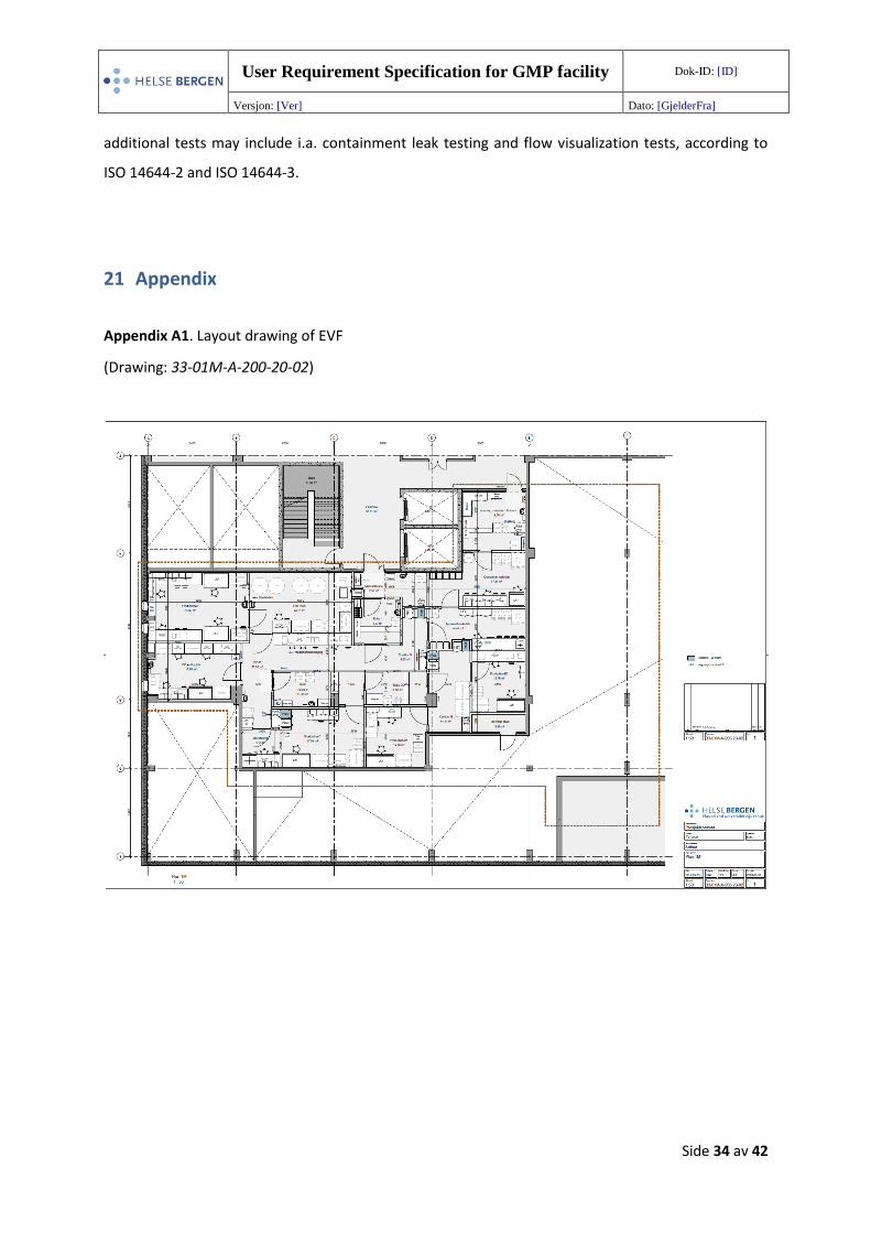
5.2 Description of layout
A brief description of all rooms is shown in Table 3 and the layout is shown in Appendix A1, and the
classification of clean rooms is shown in 129995-RIV-TEG-002. The facility has two grade B production
rooms where the biological safety cabinets (BSCs) provide a grade A manufacturing area for
substantial manipulation of cells (ISO-5). There is also one grade C production room (ISO-7), and a
grade D production room (ISO-8) for minimal manipulation of human cells. Minimal cell manipulation
performed in the grade D production room will be first and foremost dedicated to activities related
to hospital routine preparation of stem cell products, such as centrifugation and freezing of cells.
There is also a room for conducting controlled-rate freezing of products, where tanks filled with
liquid nitrogen are used for cryopreservation of products. Access to manufacturing clean rooms is
through supporting corridors and gowning sluices where personnel change into appropriate clothing
before accessing the various rooms.
Ancillary materials arrive through the dedicated entrance for incoming goods (Sluice 4), where goods
are checked and cleaned before being put in quarantine. All ancillary materials are kept under
quarantine after receipt until being inspected for rejection or approval. Then approved materials are
moved to the approved material storage area.
Finally, there is a quality control (QC) area which is spatially separated from the production area and
divided into several work stations based upon the activities to be executed. All starting/raw materials
enter the facility through the main entrance and will be registered after receipt at a dedicated work
station in corridor D. The quality control testing of all starting materials, intermediate products and
final products will be performed in the QC testing lab, where there is i.a. a BSC and flow cytometer.
User Requirement Specification for GMP facility Dok-ID: [ID]
Versjon: [Ver] Dato: [GjelderFra]
Side 12 av 42
Finally, finalized products will be packaged at dedicated work stations (in LN2 room for products
manufactured in grade D, or in corridor D for products manufactured in grade B or C). Adjacent to
the QC area, there is also a room dedicated for microbiological testing, including storage of settle and
contact plates and recording of the results.
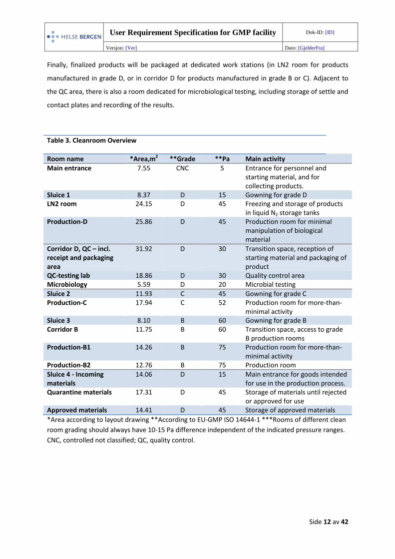
Table 3. Cleanroom Overview
Room name *Area,m2 **Grade **Pa Main activity
Main entrance 7.55 CNC 5 Entrance for personnel and starting material, and for collecting products.
Sluice 1 8.37 D 15 Gowning for grade D LN2 room 24.15 D 45 Freezing and storage of products
in liquid N2 storage tanks Production-D 25.86 D 45 Production room for minimal
manipulation of biological material
Corridor D, QC – incl. receipt and packaging area
31.92 D 30 Transition space, reception of starting material and packaging of product
QC-testing lab 18.86 D 30 Quality control area Microbiology 5.59 D 20 Microbial testing
Sluice 2 11.93 C 45 Gowning for grade C Production-C 17.94 C 52 Production room for more-than-
minimal activity Sluice 3 8.10 B 60 Gowning for grade B Corridor B 11.75 B 60 Transition space, access to grade
B production rooms Production-B1 14.26 B 75 Production room for more-than-
minimal activity Production-B2 12.76 B 75 Production room
Sluice 4 - Incoming materials
14.06 D 15 Main entrance for goods intended for use in the production process.
Quarantine materials 17.31 D 45 Storage of materials until rejected or approved for use
Approved materials 14.41 D 45 Storage of approved materials
*Area according to layout drawing **According to EU-GMP ISO 14644-1 ***Rooms of different clean
room grading should always have 10-15 Pa difference independent of the indicated pressure ranges.
CNC, controlled not classified; QC, quality control.
User Requirement Specification for GMP facility Dok-ID: [ID]
Versjon: [Ver] Dato: [GjelderFra]
Side 13 av 42
5.3 Flow in the facility
The facility will assure a logical flow of material and personnel within the facility to assure the
manufacturing of products according to GMP guidelines. Material and personnel have different
routes into and out of production cleanrooms for more-than-minimal manipulation. Materials enter
grade C and grade B production rooms through material airlocks (MALs) while personnel enter
through controlled-access gowning rooms (sluices).
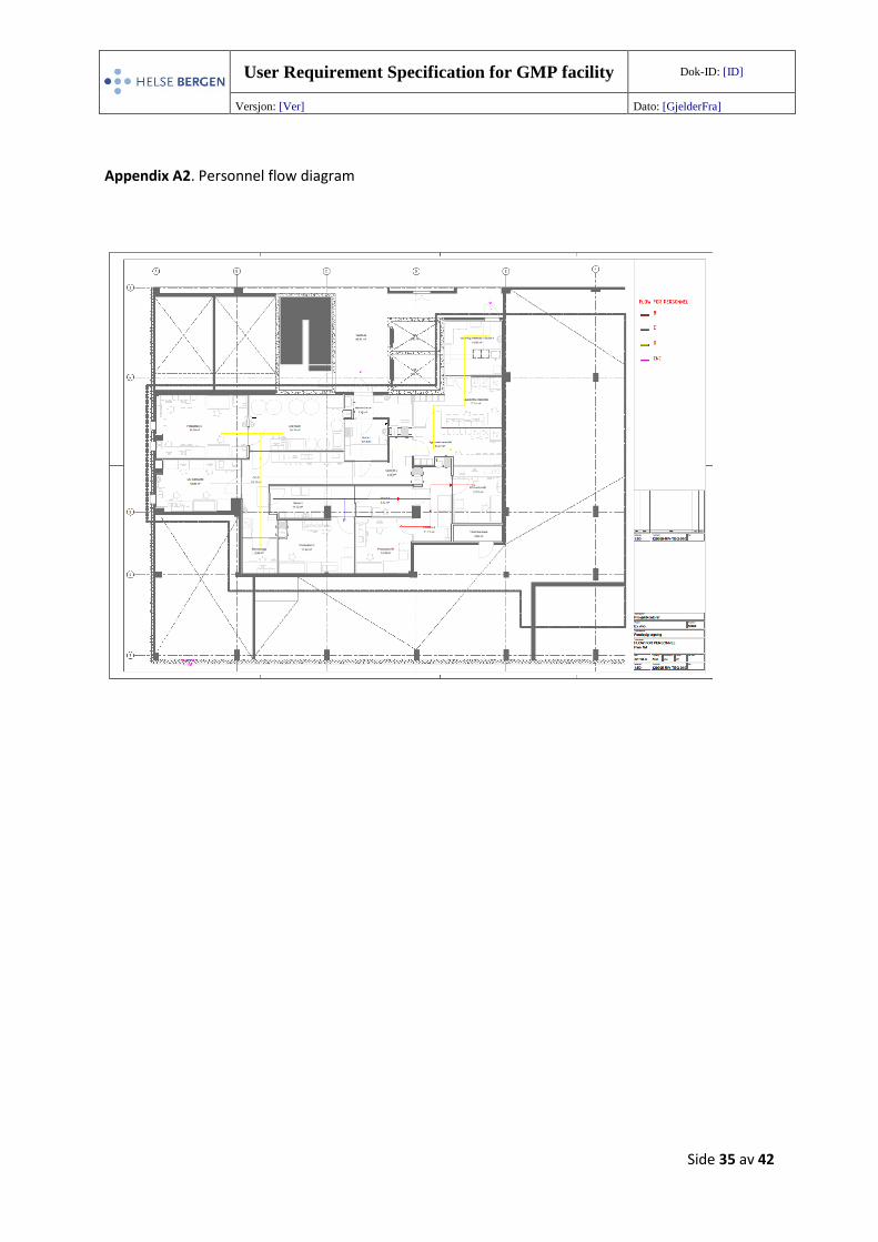
5.3.1 Personnel flow
Personnel will primarily enter the facility through the key-card controlled main entrance. Outdoor
shoes and clothing is not brought into the facility. Personnel will gown appropriately in Sluice 1
before entering Corridor D. From Corridor D, the personnel can either enter i) the liquid nitrogen
storage room (ii) the grade D production room by bypassing the liquid nitrogen storage room iii) the
QC area iv) the grade C production room after gowning in Sluice 2 or v) the grade B production rooms
after gowning in Sluice 3 and bypassing Corridor B. A limited number of people should generally be
present in the clean rooms. Personnel enter and leave the clean rooms through the same sluices, so-
called bidirectional flow. An overview of the personnel flow is shown in Appendix A2 (129995-RIV-
TEG-010). Detailed description of i.a. gowning procedures and behavior in the clean rooms are
described in SOPs.
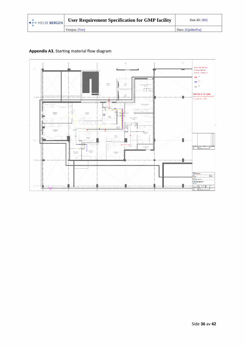
5.3.2 Starting material and (intermediate/final) product flow
Starting material to be used in manufacturing rooms will enter the facility through the main entrance
where outer packaging is cleaned and transferred to corridor D through a MAL (PB01), see Appendix
A3 (129995-RIV-TEG-007) showing a flow diagram for starting material. The material will be
transported by personnel to the receipt desk in corridor D dedicated for inspection, labelling and
registration of the material. Here the approved starting material will be double-packed if necessary,
and then it will be transferred to either grade D production room (minimal manipulation) by
personnel or transferred through MALs to either grade C or grade B production rooms.
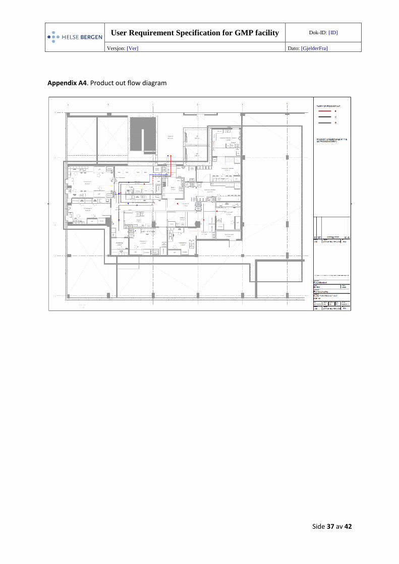
During manufacture, intermediate products for quality control testing will be transported through
MALs and brought to the QC area for QC analyses. The final product will be transported to the
dedicated area at QC for correct labelling and packaging of products. The final product is contained
adequately before being transported out of the MAL in the LN2 room, to the main entrance (see
User Requirement Specification for GMP facility Dok-ID: [ID]
Versjon: [Ver] Dato: [GjelderFra]
Side 14 av 42
Appendix A4, 129995-RIV-TEG-006). Products to be stored in the gaseous phase of liquid nitrogen
tanks are labeled, and either kept in a quarantine tank (before performing relevant tests) or in a
normal tank, before their final release.
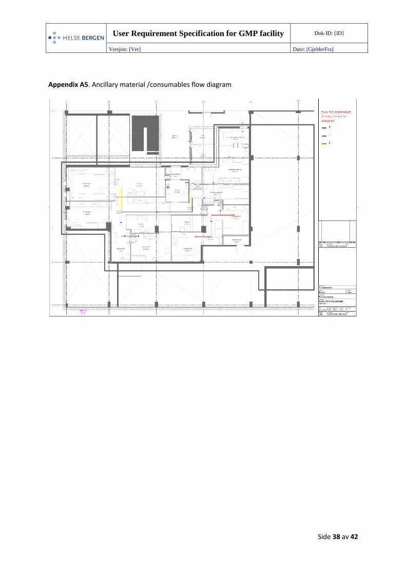
5.3.3 Ancillary material flow
Ancillary materials will enter the facility through the main entrance for materials (Sluice 4). Ancillary
materials include components, solvents, reagents and plastics used during the manufacture of cell
therapy products but are not intended to be part of the final products. Ancillary materials intended
for use in manufacture are taken into the clean rooms by personnel through a dedicated entrance
(Incoming materials – sluice 4). Materials are cleaned and disinfected according to procedures by
personnel, registered, labeled and then stored in a clearly marked quarantine area after receipt until
they are checked and approved. The materials should first be inspected for damages or other quality
impacts and freed from outer packaging if required. Materials which are out of specification or
expired are rejected and moved out of the facility. Approved material is labeled and moved to the
approved storage area. All items are visibly labeled with colored stickers according to their status
(date, quarantine, approved). Materials to be used in manufacturing processes are transferred by
personnel through dedicated MALs which allow the transfer of material between rooms. MALs are
used to transfer materials to grade B production rooms (PB06) and grade C production room (PB07).
Materials to be used in grade D production room are brought into the room by the personnel.
Ancillary materials to be used in quality control analyses or for microbiological testing, and
equipment as well as parts of equipment, also follow the same route into the facility; and after
approval, they can be transferred to their respective rooms for their intended use. An overview of
the ancillary material /consumable flow is shown in Appendix A5 (129995-RIV-TEG-009).
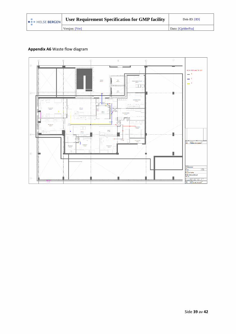
5.3.4 Waste flow
Waste will be contained in plastic bags and transported out of the facility through MALs according to
the flow chart shown in Appendix A6 (129995-RIV-TEG-008). Waste bins suitable for clean rooms are
present in rooms where necessary. The waste will be collected from the MALs and taken out of the
facility before activity closes down for the day, according to standard procedures. A dedicated area is
situated in the main entrance for waste disposal. Liquid waste that poses no risk to the environment
or health can be emptied in the sink situated in the QC testing lab or else it can be packaged in a
sealed box and transported out of the facility with other solid wastes.
User Requirement Specification for GMP facility Dok-ID: [ID]
Versjon: [Ver] Dato: [GjelderFra]
Side 15 av 42
5.3.5 Gowning rooms and material airlocks
Gowning rooms, also called sluices, are of appropriate size so at least two people can be in the room
simultaneously while one person is gowning. All personnel will follow a written procedure on how to
enter the respective room to minimize contamination of clean areas and clean-area clothing. Sluices
are separate rooms designed such that the last airlock has the same clean room grade as the
corridor/room it leads into. Clean protective garments will be provided in each sluice which will be of
sufficient size to change clothes. The sluices will be flushed with filtered air to minimize microbial and
particulate contamination. Airflow patterns must minimalize contamination risk (avoiding particle
flow from particle-generating personnel/equipment to zone of higher risk for the product). In critical
areas or contamination risk areas (where trolleys are used), special floor-cover/sticky mats may be
used to reduce contamination. Transport of ancillary materials, consumables etc between different
rooms is performed using material airlocks (MALs), also called passboxes (PB). These MALs help to
control the contamination risk and reduce the level of human intervention.
6 Operational requirements
6.1 Operation time
Normal operation time is between 06 am till 8 pm on working days, but 24/7 operation must be
possible in periods. Monitoring of the facility is automated and done continuously, though fan/filter
units are programmed to scale back to lower speed, such as “night mode”, to reduce energy
consumption when the facility is not in use.
6.2 Access control
All entrance in and out of the facility is logged electronically using access cards. An access control
system will assure that only authorized people can enter the classified clean room areas, using a pin
code system, thus these areas are access-restricted (see 129995-XX-1M-E-543-20-01). Personnel
must be sufficiently trained in i.a. personnel movement and gowning procedures, before being
authorized to work in the facility. Each personnel must also be specifically trained for the appropriate
grade of clean room where the personnel will be working. Training is documented and maintained
continuously according to GMP guidelines. Under certain circumstances, such as during training of
User Requirement Specification for GMP facility Dok-ID: [ID]
Versjon: [Ver] Dato: [GjelderFra]
Side 16 av 42
new personnel and supervisory situations, personnel may enter the facility while being accompanied
by trained personnel.
6.3 Microbiological monitoring
The facility will be routinely monitored with regard to microbiological count (viable particles).
Sampling of aseptic processing areas is done after each operating shift; details about frequency and
location of sampling and monitoring procedures will be described in SOPs. Reading of plates is
performed in the Microbiology room which has a lower pressure than the adjacent room, to prevent
air leakage.
7 External additional supporting facilities
Floor 1, directly beneath the facility, will be used for technical installations and the computer server
system. A small area of 3.5m2 is available for technical installations on floor 1M.
8 Central monitoring system
Monitoring is performed with a system called Facility Monitoring System (FMS, environmental
monitoring) while control and regulation are performed by a Building Management System (BMS).
The FMS will be provided by the Vendor and used to test that the clean rooms are performing as
required, both at rest and in operation. The FMS should at minimum meet the requirements
specified by EU-GMP and be UPS-powered. Monitors will be placed at convenient places in the
facility, so personnel can easily see the status of clean rooms before entering.
The final number and location of critical sensors shall be determined by means of a risk assessment
and compliance with ISO 14644 in detail design, performed by the supplier and the users. Continuous
monitoring of the facility will be performed and each room will have the necessary integrated
sensors to automatically record and store the following parameters for later documentation:
• Number of airborne particles per cubic meter of air
• Pressure and differential pressure (pressure difference between rooms / pressure regime)
• Temperature
• Relative humidity (% RH)
User Requirement Specification for GMP facility Dok-ID: [ID]
Versjon: [Ver] Dato: [GjelderFra]
Side 17 av 42
• Air flow
• Airlock status (door open/ajar)
• Equipment alarm systems (including freezer, refrigerator, incubator)
In addition, a warning system should indicate failure to meet the requirements and send alerts via
email and telephone. The system should have an analysis and reporting tool and also be fully
configurable, user-friendly and maintainable. The alarm system is shown in diagram 129995-XX-1M-
E-563-20-01_Rev2.
In addition, alarms and monitoring of air quality in BSCs shall automatically be monitored
continuously and have real-time data collection (particle counters), and this monitoring is integrated
into the larger FMS.
9 Lighting and acoustics
9.1 Lighting
Adequate lighting must be present in all areas of the facility, according to the different processes
performed in each room and to maintain a good working environment for personnel. Three windows
will be placed in the facility to allow natural light into two of the rooms, with two windows in
Production-D room and one in QC-testing lab, where it is expected that personnel will spend a lot of
their time. Direct sunlight into the facility, which might increase the temperature, is not considered a
problem as the building is facing north-west on the first floor.
Artificial lighting should be adjustable, with the possibility of three levels of lighting. There should be
between 3500-6500 Kelvin, with tunable white to easily change the color temperature. Long-lived
LED lights have a required life cycle of 20 years without maintenance (and clean room
reclassification). They should be corrosion-resistant, as well as dust and water-resistant. If
maintenance of lighting is not possible from the roof of the facility, then appropriate protocols must
be in place when changing lights from the inside (enclosed panels) with appropriate fixtures. Light
panels must also tolerate cleaning and disinfection solvents over time. A motion sensor turns light on
automatically and light is kept on in Corridor-D as long as someone is inside the facility. Lights can be
coupled between certain rooms and turned on as a group in several rooms.
9.2 Acoustics
Walls and material in general should be noise cancelling where possible, to reduce noise from i.a.
equipment, ventilation systems and ventilated hoods. Technical regulations refer to Norwegian
Standard NS 8175 - "Sound conditions in buildings - Sound classification of different building types".
User Requirement Specification for GMP facility Dok-ID: [ID]
Versjon: [Ver] Dato: [GjelderFra]
Side 18 av 42
Class C is the sufficient/minimum requirement. Furthermore, we would like to point out the
Regulations for Action and Limit Values (FOR-2011-12-06-1358) where EVF will belong to Group 2
working conditions. For new buildings it’s desirable to achieve minimum ten decibels below the limit
value.
10 Utilities
10.1 Water
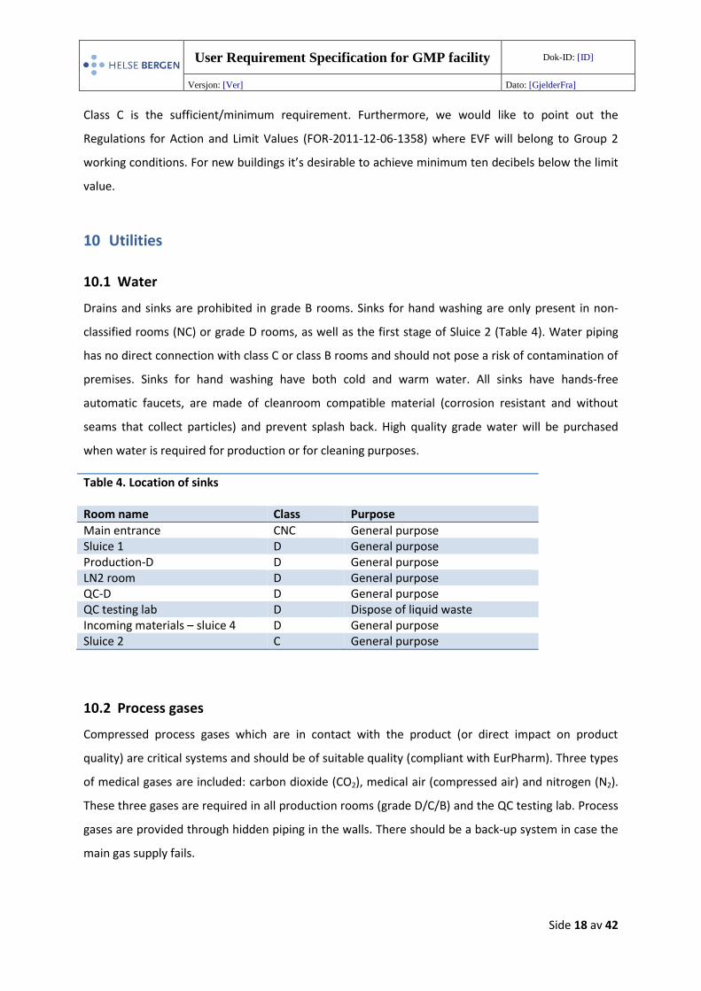
Drains and sinks are prohibited in grade B rooms. Sinks for hand washing are only present in non-
classified rooms (NC) or grade D rooms, as well as the first stage of Sluice 2 (Table 4). Water piping
has no direct connection with class C or class B rooms and should not pose a risk of contamination of
premises. Sinks for hand washing have both cold and warm water. All sinks have hands-free
automatic faucets, are made of cleanroom compatible material (corrosion resistant and without
seams that collect particles) and prevent splash back. High quality grade water will be purchased
when water is required for production or for cleaning purposes.
Table 4. Location of sinks Room name Class Purpose
Main entrance CNC General purpose Sluice 1 D General purpose Production-D D General purpose LN2 room D General purpose QC-D D General purpose QC testing lab D Dispose of liquid waste Incoming materials – sluice 4 D General purpose Sluice 2 C General purpose
10.2 Process gases
Compressed process gases which are in contact with the product (or direct impact on product
quality) are critical systems and should be of suitable quality (compliant with EurPharm). Three types
of medical gases are included: carbon dioxide (CO2), medical air (compressed air) and nitrogen (N2).
These three gases are required in all production rooms (grade D/C/B) and the QC testing lab. Process
gases are provided through hidden piping in the walls. There should be a back-up system in case the
main gas supply fails.
User Requirement Specification for GMP facility Dok-ID: [ID]
Versjon: [Ver] Dato: [GjelderFra]
Side 19 av 42
10.3 Liquid nitrogen
Liquid nitrogen (LN2) will be used for storage of cells in closed containers, and will be supplied
through piping to 1M from the main supply tank for HelseBergen.
11 HVAC requirements
An air handling unit (AHU) controls the air in the facility, with a cooling, heating and (de)humidifying
system (see 129995-RIV-TEG-004). The HVAC system should be appropriate for the activities
performed and should not negatively affect the products/ATMPs or functioning of the equipment;
and specifications should also be met continuously all year, also with equipment and people present
in rooms (in operation and at rest). The HVAC system should be in compliance with ISO 14644.
Detailed information of the HVAC system can be found in the URS for EVF HVAC and Utility and the
HVAC principle drawing (129995-RIV-TEG-004) and flowsheet for air distribution (129995-RIV-TEG-
005).
11.1 Air changes
A dedicated and efficient HVAC system will continuously supply and distribute required volume and
quality of air to the facility, with uniform air distribution (avoiding airflow turbulence), in accordance
with ISO 14644 (see 129995-RIV-TEG-012). Air supply to the clean rooms must be sufficient in order
to reach and maintain the B, C and D air grades even under stressful conditions with a maximum
number of people present per room (see Table 5). The air handling unit (AHU) conditions 100%
outside air normally once, but may recirculate clean room air, up to 75%, in order to save energy,
without compromising other URS. The AHU redundancy is nominally 1x100%, with separate air
supply and discharge “trains” (for flexible installation). However, each train should have 2x100%
capacity fan units, with motor frequency converter, all operating normally at 50 % capacity. Speed is
increased to 100% capacity (volume and pressure) in case of fan break down, in order to maintain
the pressure regime. The AHU and its distribution system are all connected to existing UPS. A
description of the HVAC system is shown in detailed diagrams. A separate new extract air ventilation
system is to eject sanitizing aerosols outside each MAL (pass box) (SHA related) and evacuate due to
a liquid N2 leakage in an emergency situation. Supply and extract air flowsheets are shown in
129995-RIV-TEG-013 and 129995-RIV-TEG-014.
The number of air changes (change rates per hours) should be calculated to provide optimal
cleanliness as required per the grades and should be related to the size of the room, the equipment
User Requirement Specification for GMP facility Dok-ID: [ID]
Versjon: [Ver] Dato: [GjelderFra]
Side 20 av 42
present and the numbers of personnel present (see Table 5). The particle limits given in the table for
the “at rest” state should be achieved after a short “clean up” period of 15-20 minutes (guidance
value) in an unmanned state after completion of operations.
11.2 Air flow
Air flow will be unidirectional in class B clean rooms (avoiding turbulence), and air flow will also be
unidirectional in BSCs where the product is exposed. Airflow should ensure the required airborne
particulate cleanliness class and avoid airflow turbulence which can create contamination.
11.3 HEPA filters and other filters
Air filtration should be set to ensure that the defined clean area classification is attained. The air
system is HEPA-filtered to obtain the clean room requirements:
• Class B and C clean rooms H13 in line filter and H14 terminal filters
• Class D clean rooms H13 in line filter
HEPA filters shall be in accordance with NS EN1822. Leak test (scanning) shall be in accordance with
NS EN 14644-3. See our URS for EVF HVAC and Utility and flowsheet for air distribution 129995-RIV-
TEG-005.
11.4 Relative humidity
The relative humidity (% RH) should ensure a good working environment for the personnel and not
pose any risk to the quality of the product. The aim is to keep 45+/-5% RH, with a lower limit of 40%
RH and a maximum of 60% RH, to minimize the risk of microbial growth and contamination. A
detailed description of a technical solution is shown in the HVAC flowsheet showing the air handling
unit and dehumidifier unit 129995-RIV-TEG-004.
11.5 Temperature
The temperature in the facility should meet the specifications even with heavy equipment and
maximum number of people in rooms. The temperature can be regulated in each room between 19-
25 degrees, and should be within +/-1◦C when a specific temperature is set. The range differs
between rooms and should ensure that the personnel have a comfortable working enviroment and
User Requirement Specification for GMP facility Dok-ID: [ID]
Versjon: [Ver] Dato: [GjelderFra]
Side 21 av 42
take into consideration the clothing requirements of the personnel in each room (lower temperature
in grade B rooms, higher temperature in sluices), and the number of people in each room. The
temperature must also be appropriate for the product, i.a. stem cell products require between 19-25
degrees so the room temperature where biological/stem cell products should never be below 19
degrees, and maximum 25 degrees.
11.6 Air tightness
The room will be air-tight as far as possible to minimize the ingress of less clean air from areas of
lower grad into areas with higher grade (more clean) due to pressure differentials.
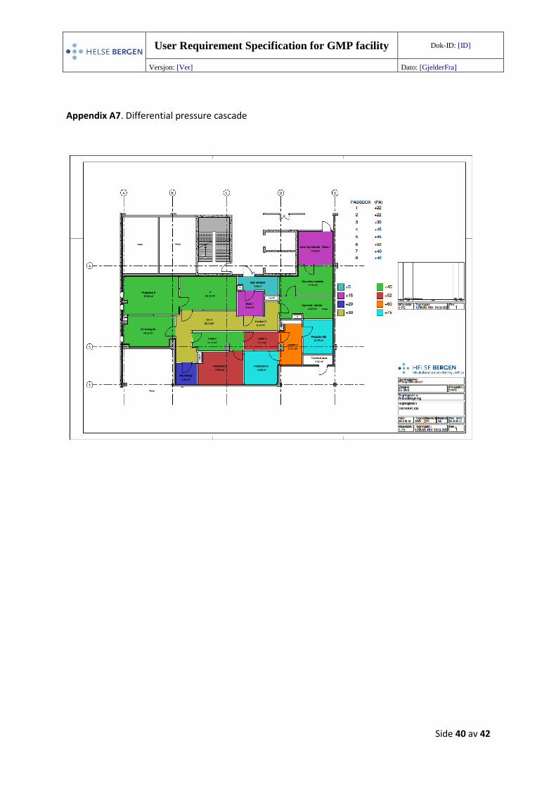
11.7 Pressure and zoning
The air pressure in all rooms of the facility are controlled, with the highest pressure in the cleanest
room to ensure that any airflow is pushed outwards from the room, and dirty air cannot enter by
default. The manufacturing rooms are the cleanest and have the highest pressure. Pressure gradients
between rooms in the facility must guaranty air cleanliness, maintain particle requirements and aid
to prevent cross contamination. In critical areas, such as between adjacent rooms of different clean
room grades, there should be a minimum pressure difference of 10-15 Pa. The pressure in each room
should aim to maintain +/-5 Pa from its set point level (specific values will be determined together
with the supplier), but must still be able to maintain the minimum pressure difference between
rooms of different clean room grades. Thus no major fluctuation should occur in directions that can
result in a less differential. There is always ascending pressure towards the cleanest areas; as shown
in Appendix A7 with a drawing of the differential pressure cascade, 129995-RIV-TEG-003. A stable
reference set point is chosen (0 Pa) nearby, outside the facility.
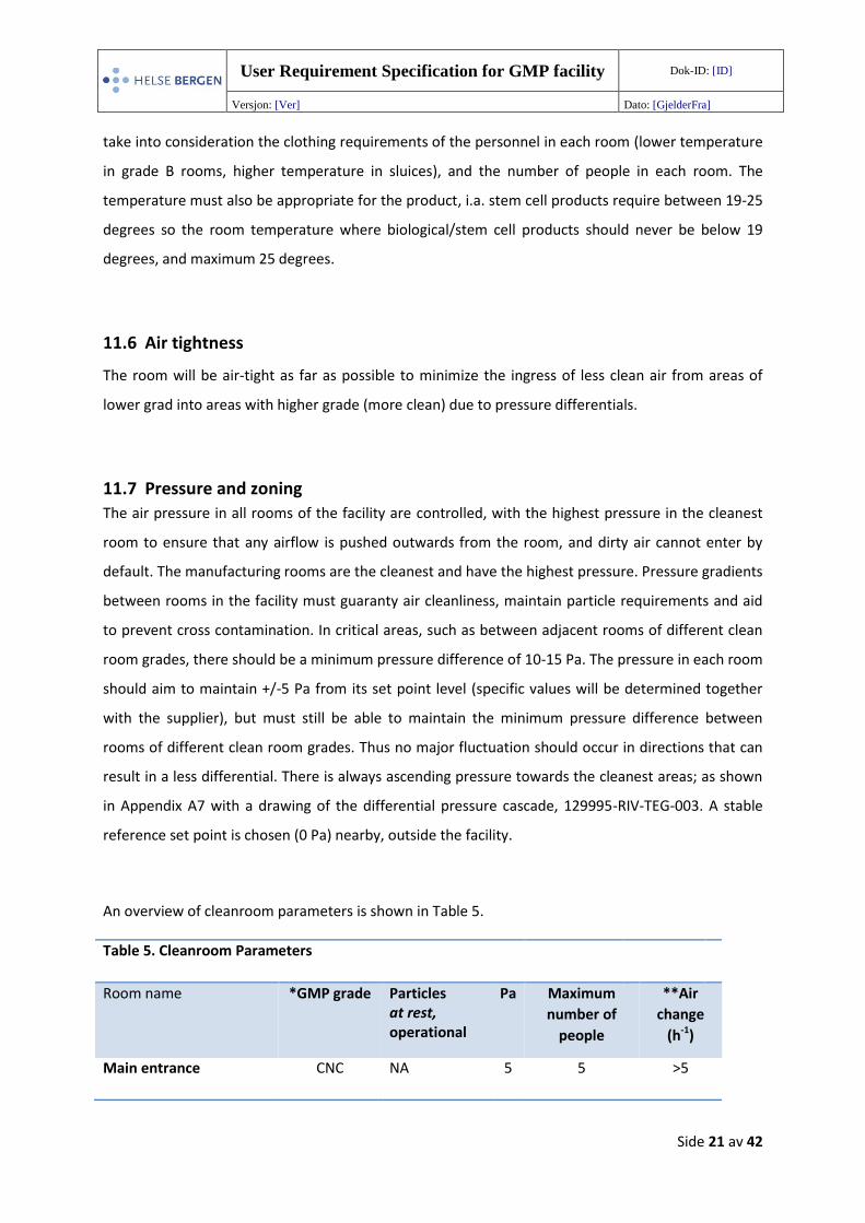
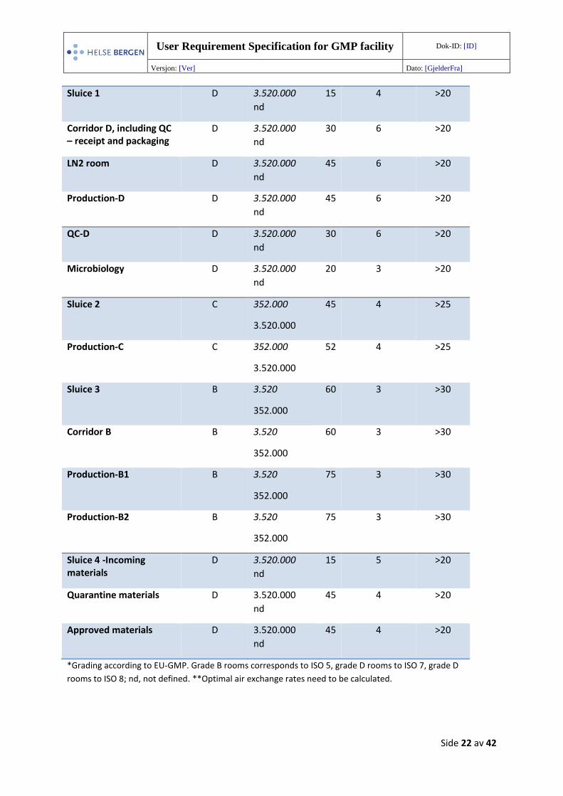
An overview of cleanroom parameters is shown in Table 5.
Table 5. Cleanroom Parameters
Room name *GMP grade Particles at rest, operational
Pa Maximum
number of
people
**Air
change
(h-1)
Main entrance CNC NA 5 5 >5
User Requirement Specification for GMP facility Dok-ID: [ID]
Versjon: [Ver] Dato: [GjelderFra]
Side 22 av 42
Sluice 1 D 3.520.000
nd
15 4 >20
Corridor D, including QC – receipt and packaging
D 3.520.000
nd
30 6 >20
LN2 room D 3.520.000
nd
45 6 >20
Production-D D 3.520.000
nd
45 6 >20
QC-D D 3.520.000
nd
30 6 >20
Microbiology D 3.520.000
nd
20 3 >20
Sluice 2 C 352.000
3.520.000
45 4 >25
Production-C C 352.000
3.520.000
52 4 >25
Sluice 3 B 3.520
352.000
60 3 >30
Corridor B B 3.520
352.000
60 3 >30
Production-B1 B 3.520
352.000
75 3 >30
Production-B2 B 3.520
352.000
75 3 >30
Sluice 4 -Incoming materials
D 3.520.000
nd
15 5 >20
Quarantine materials D 3.520.000
nd
45 4 >20
Approved materials D 3.520.000
nd
45 4 >20
*Grading according to EU-GMP. Grade B rooms corresponds to ISO 5, grade D rooms to ISO 7, grade D
rooms to ISO 8; nd, not defined. **Optimal air exchange rates need to be calculated.
User Requirement Specification for GMP facility Dok-ID: [ID]
Versjon: [Ver] Dato: [GjelderFra]
Side 23 av 42
12 Electrical system
Electrical outlets are provided for power to the equipment and are shown in the drawing of the
electrical system 129995-XX-1M-E-400-20-01_Rev2, also showing which equipment has
uninterruptible power supply (UPS)-powered. Electrical in general and errors in a room should not
affect systems and equipment in other rooms. All material and design must be GMP compliant, with
smooth, round surfaces and sealed to secure air. Material can resist cleaning and disinfection.
Sluice door automation and interlocking between doors are UPS powered to maintain the
barrier in case of power outages until emergency power is available. The same applies to
evacuation in an emergency situation.
All lighting is to be of type LED, and required life cycle of 20 years (and clean room
reclassification).
All biosafety cabinets are provided with separate UPS power, to protect product even if clean
room ventilation system should break down. The monitoring system for BSCs and facility
monitoring, including monitors, are to be UPS powered. BSCs shall maintain laminar air flow
in case of power outages until emergency power is available.
The AHU and MALs are UPS-powered (risk assessment required).
With regard to the fire alarm system, the AHU is running until smoke is detected in the air
inlet duct.
Supply and extract fans are to be emergency powered, but may partly be UPS powered to
maintain clean room pressure regime. Typical scenario is in case of power outages until
emergency power is available (to be risk assessed in detail design).
The extract air system is supplied with URS (risk assessment required).
Monitoring of equipment critical parameters such as temperature should be UPS powered
(refrigerator / centrifuges / incubators).
12.1 Interlocking system
An interlocking system must be implemented with a visual warning system to avoid simultaneous
door opening. Two doors in the same sluice cannot be opened at the same time, then a visual
warning system will show a green light when the sluice is ready and doors can be opened, a red light
when the sluice is in use, or due to interlocking. See diagram for illustration of interlocking systems
(129995-RIE129995-05). Doors should generally open towards higher pressure; with a self-closer
User Requirement Specification for GMP facility Dok-ID: [ID]
Versjon: [Ver] Dato: [GjelderFra]
Side 24 av 42
system; though changes are allowed based on emergency exits or HSE requirements. A button at the
main entrance is able to override the interlocking system in the facility if neccesary.
13 Permanent furnishing and equipment
Each room should contain the minimum items of furnishing and equipment required to be
operationally, and only contain the necessary equipment required for its intended use. A complete
table/list of permanent equipment/furnishing to be supplied by the Vendor is shown in Appendix A8,
and detailed specifications for each piece of equipment/furnishing can be found in the URS for
permanent equipment. A layout drawing showing all the equipment and furnishing in the GMP facility
is shown in Appendix A1, Layout of EVF. Equipment, as shown on the layout drawing, which is not
supplied by the Vendor, should still be taken into account by the Vendor when installing/constructing
the facility, systems and other equipment. The equipment should i.a. produce a low level of noise as
possible to be in compliance with national regulations.
All equipment must be CE-marked and be documented to be in compliant with GMP requirements,
both with regard to construction and the type of materials used. The specified equipment is correctly
delivered and installed by the supplier, in accordance with an installation plan. A plan should also be
made by the vendor with a time schedule for the delivery, installation and validation of each piece of
equipment. In addition the mounting and placement of the equipment and installations should
ensure easy cleaning. The equipment should be built to minimize negative effects on the product
quality and be corrosion-resistant. Equipment fittings and services should be designed and installed,
so that maintenance and repairs can be done outside the clean room if possible. When maintenance
is carried out within a clean area, clean instruments and tools should be used and the area must be
cleaned adequately.
13.1 Biological safety cabinets and MALs Biological safety cabinets (also referred to as laminar air flow benches) and MALs (also referred to as
pass boxes) are described in more detail in a separate URS (URS for permanent equipment). A class II
BSC will be situated in each grade B manufacturing room, providing a grade A environment to
perform the most critical processes. Other rooms will also contain BSCs, including Production room
grade C, Production room grade D, the QC testing lab and the Quarantine materials room, as seen in
Appendix A1 (Layout of EVF).
User Requirement Specification for GMP facility Dok-ID: [ID]
Versjon: [Ver] Dato: [GjelderFra]
Side 25 av 42
MALs are installed with a defined air change rate and positive pressure for transferring materials
between rooms with different pressure. MALs should be at least 500x500x500 mm (HxWxD, interior
measurements) for transfer of products and goods, and for waste they should be 1000x600x600 mm
(HxWxD, interior measurements). Air change rate should be sufficient to ensure transfer between
clean room grades, with >50 air change (h-1). Objects are sprayed with disinfectant before being
placed in the MALs, and therefore spot ventilations must be installed beside MALs to protect users
when disinfectant sprays are used, with a see-through hood, with an air change of 150 m3/h.
MALs are interfitted with HEPA filters to maintain particle control when situated between rooms
with different cleanroom grades. The MALs have an interlocking system, and only one door of the
MAL can be opened at a time (thus both doors cannot be opened simultaneously). They are all
dynamic (ventilated system inside) to prevent the entrance of contamination into the most clean
areas (see Appendix A7, 129995-RIV-TEG-003), and their efficiency must be validated.
13.2 Communication system
A communication/intercom system allows personnel to easily communicate with anyone else in
other rooms in the facility. Telephones suitable for the different grade of cleanliness are also situated
where specified to communicate with contacts outside the facility, and also function as a back-up
system if intercom should break down. Telephones must have a smooth surface which will not trap
particulate matter, with buttons that are easy for gloved hands to use, and should also be easy to
clean and resistant to alcohols and cleaning agents. Certain rooms will have a monitor and/or door-
opening function. A description is shown in the drawing of the communication system (see 129995-
XX-1M-E-535-20-01_Rev2). In addition, alarm panic buttons will be present in grade B and grade C
Production rooms as well as the LN2 room.
13.3 Computer system
Computers must be applicable for clean rooms of different grades (D/C/B), including being
waterproof, dustproof and easy to disinfect. Computers must be compatible with the HelseVest IKT
system, such as ACL OR-PC slim series, and should be installed together with HelseVest IKT system.
14 Cleaning and sanitizing agents
Disinfectants and detergents are of such a character that they are tolerable for materials of the
equipment and facility surrounding, and also fulfill their purpose to adequately kill microbial
contaminants. Storage cabinets for cleaning supplies are situated in several areas in the facility.
User Requirement Specification for GMP facility Dok-ID: [ID]
Versjon: [Ver] Dato: [GjelderFra]
Side 26 av 42
Ethanol will be used as a detergent, and disinfectants for cleaning may include, biquanide, klercide
quat, klercide amine or similar agents appropriate for cleanrooms. Clean room flooring/mats are
situated at critical areas to reduce and prevent contamination. Materials in building construction,
flooring, walls, equipment material and surfaces, and steering panels (for light or electricity etc) must
all tolerate the detergent and disinfection agents.
15 Methods of construction
The overall construction of the facility should aim to minimalize the introduction, generation and
retention of viable and non-viable particles inside the rooms, including dust, lubricants and microbes
to minimize the production of particles or other substances that may contaminate or have a negative
influence on the product, and should be in accordance with WHO TRS Annex 6, §11.1-11.7.
Construction should also support efficient operation and maintenance of the facility and permanent
installations, e.g. rooms must have smooth surfaces that are easy to clean and that don`t create
surfaces where microorganisms will thrive. The facility is also designed to facilitate efficient cleaning
and disinfection, so pipework, light fittings and ventilation points should be accessible from the
outside (WHO TRS Good manufacturing practices for biological products, Annex 3, §12.28-12.29) or a
protocol must be in place for maintenance/cleaning from the inside. In addition, construction should
be done in such a way as to enhance the life-time of the facility.
15.1 Interior finishes and materials
Interior finishes should have smooth, impervious and unbroken surfaces that are cleanable and
resistant to disinfectants. There should be a minimum of projecting cupboards and equipment, and
ceilings along with pipes and ducts from utilities should be sealed to prevent contaminations. Wiring
and cables are enclosed in conduit where possible to minimalize accumulation of dirt and dust.
Flooring should be impervious; it must cover the floor and continue along the walls and corners
avoiding dead angles, and should be of material resistant to sanitizing agents such as vinyl, and
tolerate regularly cleaning. Silicone sealant of appropriate quality for clean rooms is used where
necessary to have smooth surfaces and seal openings. Cleanroom flooring/mats are located at the
main entrance and in front of the entrance into Sluice 2 (gowning room). Other important junctures
such as where equipment is passed into the cleanroom may also have cleanroom flooring/mats if
found necessary. Mats are designed to capture dirt, dust and debris from foot traffic and equipment
wheels by allowing particles to adhere to the adhesive coat on the mat. In the grade D room where
User Requirement Specification for GMP facility Dok-ID: [ID]
Versjon: [Ver] Dato: [GjelderFra]
Side 27 av 42
liquid nitrogen containers are situated, there should be flooring around the containers such as metal,
which can resist liquid nitrogen.
Glass walls are used where possible, to let in light and reduce a feeling of isolation, and also so
supervisory personnel may visualize operation of processes ongoing in grade C or B areas while
standing in lesser clean areas. Walls and material in general should be noise cancelling where
possible (rooms are class C minimum, according to Forskrift om tiltak og grenseverdier), to reduce
noise from i.a. equipment, ventilation systems and ventilated hoods. Pipes and ducts and other
utilities should be installed so that they do not create recesses, unsealed openings and surfaces
which are difficult to clean. A more detailed description of interior finishes and materials can be
found in the report 129995-TVF-Beskrivelse.
15.2 Doors
All doors should open into the room with the highest pressure unless documented that power-
assisted doors function efficiently in either direction. Doors should be large enough to move
equipment in and out of the modular clean room (for maintenance or exchange), and doors as well
as corridor D must be wide enough to allow transport of nitrogen tanks (1100mm diameter) out of
the facility if necessary. Doors are preferable of glass where possible/applicable. Double-leafed doors
are preferable, with a door of at least 900mm and a side panel of at least 200mm which can be
opened when needed, though prevention of air leakage should be guaranteed long-term. All doors
inside the facility open automatically with a motion sensor and some doors are interlocked. There
are also certain doors that can only be opened using a keypad access control system.
16 Regulatory Requirements
The facility, equipment and related activities shall comply with the EU GMP requirements described
in the EudraLex, Volume 4, Good Manufacturing Practice (GMP) guidelines. Volume 4 of “the rules
governing medicinal products in the European Union” contains guidance for the interpretation of the
principles and guidelines of GMP for medicinal products for human and veterinary use laid down in
Commission Directives 91/356/EEC, as amended by Directive 2003/94/EC, and 91/412/EEC,
respectively. The facility must be built so that the rooms, and equipment, are in accordance with the
EU GMP requirements and guidelines and to obtain approval by the obtain approval by the
Norwegian Medicines Agency.
User Requirement Specification for GMP facility Dok-ID: [ID]
Versjon: [Ver] Dato: [GjelderFra]
Side 28 av 42
16.1 GMP and relevant guidelines
The facility shall comply with the EU GMP guidelines as described in the EudraLex - Volume 4 - Good
Manufacturing Practice (GMP) guidelines, Part I and Part IV.
Other relevant international guidelines and codes are as followed:
The Pharmaceutical Inspection Convention and Pharmaceutical Inspection Co-operation
Scheme (PIC/S), Guide to good manufacturing practice for medicinal products, part 1; latest
version.
International Conference of Harmonization, ICH Q7A
International Society for Pharmaceutical Engineering (ISPE), latest editions.
FACT-JACIE International Standards for Hematopoietic Cellular Therapy Product Collection,
Processing, and Administration (FACT – JACIE Joint Accreditation Committee ISCT-Europe &
EBMT)
US FDA Guidance for Industry, Sterile drug products produced by aseptic processing - current
good manufacturing practice, by U.S. Department of Health and Human Services, FDA, CDER,
CBER, ORA.
WHO Technical Report Series (TRS). (incl Annex 3, 4 and 5)
16.2 International standards and codes
NS EN ISO 14644 Series Cleanroom Standards:
o 14644-1, Title: Classification of air cleanliness by particle concentration
o 14644-2, Title: Monitoring to provide evidence of cleanroom performance related to
air cleanliness by particle concentration
o 14644-3, Title: Test methods
o 14644-4, Title: Design, construction, and start-up
NS EN 1822 Series for High efficiency air filters(EPA, HEPA og ULPA)
NS EN 12469 Biotechnology - Performance criteria for microbiological safety cabinets
NS 8175:2012 Acoustic conditions in buildings - Sound classification of various types of
buildings
European Pharmacopeia.
User Requirement Specification for GMP facility Dok-ID: [ID]
Versjon: [Ver] Dato: [GjelderFra]
Side 29 av 42
16.3 Norwegian regulatory requirements
Lov om legemidler (legemiddelloven)
Forskrift om legemidler (legemiddelforskriften)
Forskrift om tilvirkning og import av legemidler (tilvirkningsforskriften)
Forskrift om legemidlers kvalitet, standarder m.m.
Forskrift om håndtering av humane celler og vev
Norske legemiddelstandarder (NLS)
Forskrift om om Systematisk helse-, miljø og sikkerhetsarbeid i virksomheter
(Internkontrollforskriften)
Lov om planlegging og byggesaksbehandling (plan- og bygningsloven)
Lov om arbeidsmiljø, arbeidstid og stillingsvern mv. (Arbeidsmiljøloven).
Forskrift om utforming og innretning av arbeidsplasser og arbeidslokaler
(Arbeidsplassforskriften)
Forskrift om tiltaksverdier og grenseverdier for fysiske og kjemiske faktorer i arbeidsmiljøet
samt smitterisikogrupper for biologiske faktorer (forskrift om tiltaks- og grenseverdier)
Veiledning om klima og luftkvalitet, best. nr. 444 fra Arbeidstilsynet.
17 Documentation The Vendor must comply with good documentation practice and deliver the necessary
documentation to prove that the facility, system and equipment is constructed according to GMP
guidelines and in line with our URS. Thus, it must be documented that the materials used are
compliant with GMP guidelines and the appropriate validation tests have been performed. Checklists
should be used to validate that all parts of construction, equipment and systems are in concordance
with GMP guidelines. These should include, but not be limited to: the material used, quality
specification, certificates, test methods/protocols, responsible test person, number of tests
performed, test results, transfer plans and reports, IQ, OQ, PQ, Certificate of Analyses (CoA)
/Compliance (CoC), validation and documentation. Guidelines for documentation can also be found
in the requirement specifications and the report 129995-TVF-Beskrivelse.
User Requirement Specification for GMP facility Dok-ID: [ID]
Versjon: [Ver] Dato: [GjelderFra]
Side 30 av 42
18 Commissioning Commissioning is performed by the Vendor and is defined as the process by which the facility,
systems and equipment are tested to ensure/verify that the design of the facility is fit for its intended
use, according to good engineering practice (GEP). The facility, equipment, utilities and environment
must meet both the URS and regulatory requirements. The commissioning process starts at the pre-
design phase and continues through construction until the final qualification is performed; it can be
divided into phases of pre-design, design, construction and operation.
19 Qualification and validation
The Vendor is responsible for preparing a validation program and validation plans. This program/plan
should provide an overview of what shall be validated, responsibiites during validation, along with a
time table and order of the validation process. The premises, technical installations, and equipment
must be qualified and validated by the Vendor to establish that all is adequate for the intended
operations, according to EU GMP annex 15 and WHO guide to GMP requirements, part 2: Validation.
The project management group has prepared a Validation master plan (VMP for EVF), which the
Vendor should give input on based upon their Validation program and which afterwards will be
finally approved.
Validation procedures should be developed either as separate procedures or integrated into
protocols and or tests. All tests performed by IQ, OQ and PQ shall be performed in accordance with
approved and detailed protocols and procedures, as described in VMP for EVF.
A validation group should be set up with at least one representative from HUS and the
representative from HUS will follow the project closely under the whole process (see VMP for EVF).
Authorized personnel must approve protocols and reports, and any changes in documents should be
approved by a validation group. The validation work must be completed as defined in specific
approved protocols. All results must be recorded as they are obtained. If changes have to be made to
documents that have been approved by the validtion group, the validation group must be informed
and approve the new changes before the work can proceed.
Among other, the volume of air and change rates must be documented to be correct and stable over
time. The air flow must be shown to not impose a contamination risk. Test should show that valves
etc are situated correctly in rooms, also when all equipment is in place in each room. The particle
counts should be tested according to ISO 14644-1. The cleanliness of rooms, including viable
User Requirement Specification for GMP facility Dok-ID: [ID]
Versjon: [Ver] Dato: [GjelderFra]
Side 31 av 42
particles, shall be according to GMP requirements. The validation will be divided into several
different actions, because each one of them will be completed at different times.
Validation elements to be identified include, but are not limited to;
• VMP Validation Master Plan (this document)
• VP Validation Plans
• FAT Factory acceptance test
• SAT Site acceptance test
• URS User Requirement Specification
• DQ Design Qualification
• IQ Installation Qualification
• OQ Operational Qualification
• PQ Performance Qualification
• PV Process Validation
• VSR Validation Summary Report
The Validation Summary Report (VSR) should sum up all the activities and results and together with
the VMP forms the basis upon which the Norwegian Medicines Agency (SLV) can approve the facility.
HUS will submit a manufacturing authorization to SLV based upon the VSR. The VSR must be
authorized by the Validation Group, and the end-users approval of the VSR creates a foundation for
being able to start production.
19.1 Validation elements
The validation activities will be divided into several different areas, because each one of them will be
completed at different times. Separate validation plans will give a detailed requirement description
for the different validation activities, including:
Validation and Qualification of facilities and utilities, including HVAC system
Validation and Qualification of equipment, in production and QC laboratory
Process validation of manufacturing processes
Validation of QC methods and test methods
Computer system validation
Cleaning validation
Interval based requalification
User Requirement Specification for GMP facility Dok-ID: [ID]
Versjon: [Ver] Dato: [GjelderFra]
Side 32 av 42
19.2 Factory acceptance test
At Vendor’s or Manufacturer’s premises a Factory Acceptance Test (FAT) will be executed in the
presence of representatives of Purchaser. Purpose of the FAT is to assure that the equipment is ready
for shipment to the installation location. FAT will be executed according to a protocol that is to be
prepared by Vendor. Vendor will provide a FAT protocol for review (by the validation group). During
the FAT, certain items belonging to the IQ and OQ will also be checked.
Purchaser may decide to execute IQ/OQ based on IQ/OQ protocols prepared by Vendor. Therefore,
Vendor will provide with his quotation the content pages of these protocols and a separate price for
these protocols. Purchaser may decide to have Vendor execute the IQ/OQ. Vendor will provide a
separate price for this in this quotation. Vendor will give ample opportunity to Purchaser’s
representatives to execute checks required for IQ and OQ. At successful completion of the FAT,
Purchaser’s representative will authorise a Release Note thereby indicating that the equipment is
ready for shipment to site. Possibly a number of outstanding items is identified that need to be
solved before shipment takes place.
19.3 Site acceptance test
After the complete installation and final configuration, the Site Acceptance Test (SAT) will be
performed. Tests will be executed that are required to complete FAT/SAT by repeating FAT or an
acceptable subset of the test to verify that no damage has occurred during shipment and installation.
All outstanding items from FAT shall be solved.
19.4 Acceptance criteria
Specific acceptance criteria for the various qualification elements will be included in the respective
protocols provided by the Vendor. The validation is aiming for design, execution and validation in
accordance with:
• EU GMP requirements described in the EudraLex - Volume 4 - Good Manufacturing Practice
(GMP) guidelines
• Helse Bergen requirements (HSE)
• Implement SOP where necessary
User Requirement Specification for GMP facility Dok-ID: [ID]
Versjon: [Ver] Dato: [GjelderFra]
Side 33 av 42
19.5 Handover to end-users
• Knowledge transfer from supplier to end-users in the building hand-over phase
• Allowing an agreed period of time after completion to “guide” and support the end user
• Support the customer/end user through the commissioning process
• Recommendations for ordinary use
19.6 EVF in ordinary use
Ordinary use will start when the facility (including personnel) is approved by SLV. The chosen supplier
will provide:
Recommendations for ordinary use
Set up regular training sessions with potential users and facility/maintenance teams
responsible for the asset after occupation/use so they understand the systems
Operational and Maintenance (O&M) manuals and the Health and Safety File.
Use a building user guide, if appropriate, to draw attention to the important items from the
technical manuals in a pictorial, easy to follow, format for the management team.
20 Life cycle and revalidation After the cleanroom has been installed, it must be tested to check that it conforms to the stipulated
design. Critical systems must be validated. Clean areas should be qualified in accordance with ISO
14644-1 and re-qualified at appropriate intervals in accordance with ISO 14644-2. In particular,
periodic classification testing (in accordance with ISO 14664-1) is expected annually, but a risk
assessment should be performed to determine the frequency. During the lifetime of the cleanroom,
the room must be monitored and revalidated to ensure that it continually achieves the standards
required. The clean room must continue to perform efficiently and according to requirements
throughout its lifespan (Appendix A9). A monitoring plan and risk assessments must be performed to
determine the frequency of testing and validation of facility and individual processes. Certain
requirements are continuously monitored (such as pressure differentials) while others are tested at
specified maximum time intervals between tests depending on the grading of the room (cleanliness).
At specified time intervals testing will include, but not be limited to, testing of airborne particle
concentrations, air flow velocities, filter leak tests, airflow volume supply, recovery time and
User Requirement Specification for GMP facility Dok-ID: [ID]
Versjon: [Ver] Dato: [GjelderFra]
Side 34 av 42
additional tests may include i.a. containment leak testing and flow visualization tests, according to
ISO 14644-2 and ISO 14644-3.
21 Appendix
Appendix A1. Layout drawing of EVF
(Drawing: 33-01M-A-200-20-02)
User Requirement Specification for GMP facility Dok-ID: [ID]
Versjon: [Ver] Dato: [GjelderFra]
Side 35 av 42
Appendix A2. Personnel flow diagram
User Requirement Specification for GMP facility Dok-ID: [ID]
Versjon: [Ver] Dato: [GjelderFra]
Side 36 av 42
Appendix A3. Starting material flow diagram
User Requirement Specification for GMP facility Dok-ID: [ID]
Versjon: [Ver] Dato: [GjelderFra]
Side 37 av 42
Appendix A4. Product out flow diagram
User Requirement Specification for GMP facility Dok-ID: [ID]
Versjon: [Ver] Dato: [GjelderFra]
Side 38 av 42
Appendix A5. Ancillary material /consumables flow diagram
User Requirement Specification for GMP facility Dok-ID: [ID]
Versjon: [Ver] Dato: [GjelderFra]
Side 39 av 42
Appendix A6 Waste flow diagram
A5. Flow for ancillary materials,
consumables etc.
User Requirement Specification for GMP facility Dok-ID: [ID]
Versjon: [Ver] Dato: [GjelderFra]
Side 40 av 42
Appendix A7. Differential pressure cascade
User Requirement Specification for GMP facility Dok-ID: [ID]
Versjon: [Ver] Dato: [GjelderFra]
Side 41 av 42
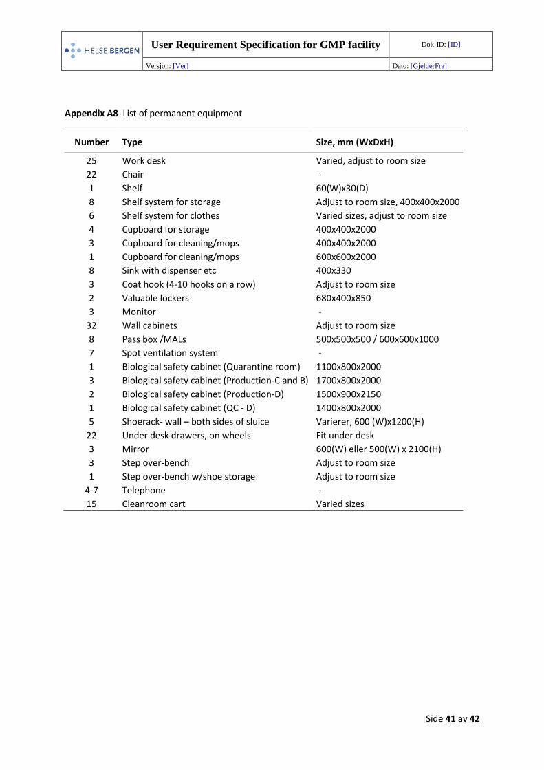
Appendix A8 List of permanent equipment
Number Type Size, mm (WxDxH)
25 Work desk Varied, adjust to room size
22 Chair -
1 Shelf 60(W)x30(D)
8 Shelf system for storage Adjust to room size, 400x400x2000
6 Shelf system for clothes Varied sizes, adjust to room size
4 Cupboard for storage 400x400x2000
3 Cupboard for cleaning/mops 400x400x2000
1 Cupboard for cleaning/mops 600x600x2000
8 Sink with dispenser etc 400x330
3 Coat hook (4-10 hooks on a row) Adjust to room size
2 Valuable lockers 680x400x850
3 Monitor -
32 Wall cabinets Adjust to room size
8 Pass box /MALs 500x500x500 / 600x600x1000
7 Spot ventilation system -
1 Biological safety cabinet (Quarantine room) 1100x800x2000
3 Biological safety cabinet (Production-C and B) 1700x800x2000
2 Biological safety cabinet (Production-D) 1500x900x2150
1 Biological safety cabinet (QC - D) 1400x800x2000
5 Shoerack- wall – both sides of sluice Varierer, 600 (W)x1200(H)
22 Under desk drawers, on wheels Fit under desk
3 Mirror 600(W) eller 500(W) x 2100(H)
3 Step over-bench Adjust to room size
1 Step over-bench w/shoe storage Adjust to room size
4-7 Telephone -
15 Cleanroom cart Varied sizes
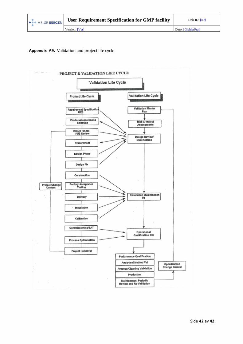
User Requirement Specification for GMP facility Dok-ID: [ID]
Versjon: [Ver] Dato: [GjelderFra]
Side 42 av 42
Appendix A9. Validation and project life cycle