Embed Size (px)
DESCRIPTION
Routing User Plane for CN
Citation preview
User Plane Routing
DN01163601Issue 3-0 en
# Nokia Siemens Networks 1 (96)
MSCDOCM14PDFCDMSC/HLR, Rel. M14.0, Product Documentation,v.3
The information in this document is subject to change without notice and describes only theproduct defined in the introduction of this documentation. This documentation is intended for theuse of Nokia Siemens Networks customers only for the purposes of the agreement under whichthe document is submitted, and no part of it may be used, reproduced, modified or transmitted inany form or means without the prior written permission of Nokia Siemens Networks. Thedocumentation has been prepared to be used by professional and properly trained personnel,and the customer assumes full responsibility when using it. Nokia Siemens Networks welcomescustomer comments as part of the process of continuous development and improvement of thedocumentation.
The information or statements given in this documentation concerning the suitability, capacity, orperformance of the mentioned hardware or software products are given “as is” and all liabilityarising in connection with such hardware or software products shall be defined conclusively andfinally in a separate agreement between Nokia Siemens Networks and the customer. However,Nokia Siemens Networks has made all reasonable efforts to ensure that the instructionscontained in the document are adequate and free of material errors and omissions. NokiaSiemens Networks will, if deemed necessary by Nokia Siemens Networks, explain issues whichmay not be covered by the document.
Nokia Siemens Networks will correct errors in this documentation as soon as possible. IN NOEVENT WILL NOKIA SIEMENS NETWORKS BE LIABLE FOR ERRORS IN THISDOCUMENTATION OR FOR ANY DAMAGES, INCLUDING BUT NOT LIMITED TO SPECIAL,DIRECT, INDIRECT, INCIDENTAL OR CONSEQUENTIAL OR ANY LOSSES, SUCH AS BUTNOT LIMITED TO LOSS OF PROFIT, REVENUE, BUSINESS INTERRUPTION, BUSINESSOPPORTUNITY OR DATA, THAT MAYARISE FROM THE USE OF THIS DOCUMENT OR THEINFORMATION IN IT.
This documentation and the product it describes are considered protected by copyrights andother intellectual property rights according to the applicable laws.
The wave logo is a trademark of Nokia Siemens Networks Oy. Nokia is a registered trademark ofNokia Corporation. Siemens is a registered trademark of Siemens AG.
Other product names mentioned in this document may be trademarks of their respective owners,and they are mentioned for identification purposes only.
Copyright © Nokia Siemens Networks 2008. All rights reserved.
2 (96) # Nokia Siemens Networks DN01163601Issue 3-0 en
User Plane Routing
Contents
Contents 3
List of tables 4
List of figures 5
Summary of changes 7
1 User plane routing 9
2 Call cases for user plane routing 11
3 Control plane signallings in MSC Server 19
4 User plane analysis 214.1 User plane analysis architecture 214.2 User plane analysis phases 264.3 User plane analysis attributes 334.4 User plane analysis results 374.5 User plane analysis execution 38
5 User plane topology database 415.1 User plane destination 425.2 User plane topology between MGWs 48
6 Relationship between user plane and control plane routing 53
7 MGW selection 577.1 MGW selection basic functionality 577.2 MGW selection optimisation based on BIWF address 727.3 MGW selection optimisation based on BCU-ID 737.4 Tandem operation in MGW selection 757.5 User plane control level MGW reselection 767.6 MGW selection in TDM routing 797.7 Call Mediation Node 80
8 Interconnecting BNC characteristics 838.1 Interconnecting BNC characteristics load sharing 838.2 Interconnecting BNC characteristics exclusion 86
9 Traffic separation between the MSS and MGW 89
10 Alarms and cause codes issued in user plane routing 91
DN01163601Issue 3-0 en
# Nokia Siemens Networks 3 (96)
Contents
List of tables
Table 1. Structure of subanalysis 23
Table 2. Normal and test sides in normal calls 24
Table 3. Normal and test sides in test calls 24
Table 4. Basic call cases 27
Table 5. User plane analysis attributes 33
Table 6. Call control logic of forming UPBREQ values 35
Table 7. Possible results of the user plane analysis 37
Table 8. Collecting load sharing weights in the MGW 61
Table 9. Selecting MGW from UPD 61
Table 10. MGW reselection 77
4 (96) # Nokia Siemens Networks DN01163601Issue 3-0 en
User Plane Routing
List of figures
Figure 1. Decomposed network architecture 9
Figure 2. MGW selection network architecture 11
Figure 3. TDM to ATM/IP 12
Figure 4. ATM to ATM, call case 1 13
Figure 5. ATM to ATM, call case 2 13
Figure 6. ATM to ATM, call case 3 14
Figure 7. ATM to ATM, call case 4 14
Figure 8. ATM to ATM, call case 5 15
Figure 9. TDM to ATM/IP through MSS 15
Figure 10. TDM to TDM through ATM/IP/TDM 16
Figure 11. CMN transit call 16
Figure 12. User plane analysis structure 21
Figure 13. A general example of a subanalysis 23
Figure 14. The relationship of different user plane analysis phases 26
Figure 15. User plane analysis results 38
Figure 16. User plane topology information 41
Figure 17. User plane destinations 44
Figure 18. User plane routed through two MGWs 48
Figure 19. UPDR parameter on the outgoing side 54
Figure 20. LBCU-ID parameter in route selection 55
Figure 21. TDM usage optimisation 60
Figure 22. MGW selection based on load sharing weights 60
Figure 23. MGW selection from the same UPDs 63
Figure 24. MGW selection from different UPDs sharing MGWs in UE-UE calls 64
Figure 25. MGW selection from different UPDs sharing MGWs in UE-CN calls 65
Figure 26. MGW selection from different UPDs sharing no MGWs 66
Figure 27. MGW selection from different UPDs with the same physical MGW 68
Figure 28. Congestion control 69
DN01163601Issue 3-0 en
# Nokia Siemens Networks 5 (96)
List of figures
Figure 29. Traffic overflow control 70
Figure 30. Alternative routing 71
Figure 31. MGW selection based on BIWF address 72
Figure 32. Delayed MGW selection based on the BCU ID 74
Figure 33. Tandem operation 76
Figure 34. MGW reselection 78
Figure 35. MGW selection in TDM routing 80
Figure 36. Call mediation node operation 81
Figure 37. ICBNC load sharing example 84
Figure 38. Traffic separation between the MSS and MGW 90
6 (96) # Nokia Siemens Networks DN01163601Issue 3-0 en
User Plane Routing
Summary of changes
Changes between document issues are cumulative. Therefore, the latestdocument issue contains all changes made to previous issues.
Changes made between issues 3–0 and 2–3
User plane topology database
The UPD-specific IPNWR parameter has been added to Sections Structureof user plane destinations and Structure of interconnection data.
Changes made between issues 2–3 and 2–2
User plane topology database
The following UPD-specific parameters have been added to SectionStructure of user plane destinations: Audio call handling method<option>, Codec Modification Support <option>, Incomingbearer redirection allowance <option>, MGW name, Outgoingbearer redirection capability <option>, and STOM <option>.
A new section has been added on codec preference list.
Changes made between issues 2–2 and 2–1
User plane topology between MGWs
Parameters Load sharing weight and ICBNC not in service flaghave been added to the list of relevant properties related tointerconnections.
DN01163601Issue 3-0 en
# Nokia Siemens Networks 7 (96)
Summary of changes
Interconnecting BNC characteristics
A new section has been added on the Interconnecting BNC characteristicsload sharing functionality and the Interconnecting BNC characteristicsexclusion functionality.
Traffic separation between the MSS and MGW
A new section has been added on the Traffic separation between the MSSand MGW functionality.
8 (96) # Nokia Siemens Networks DN01163601Issue 3-0 en
User Plane Routing
1 User plane routing
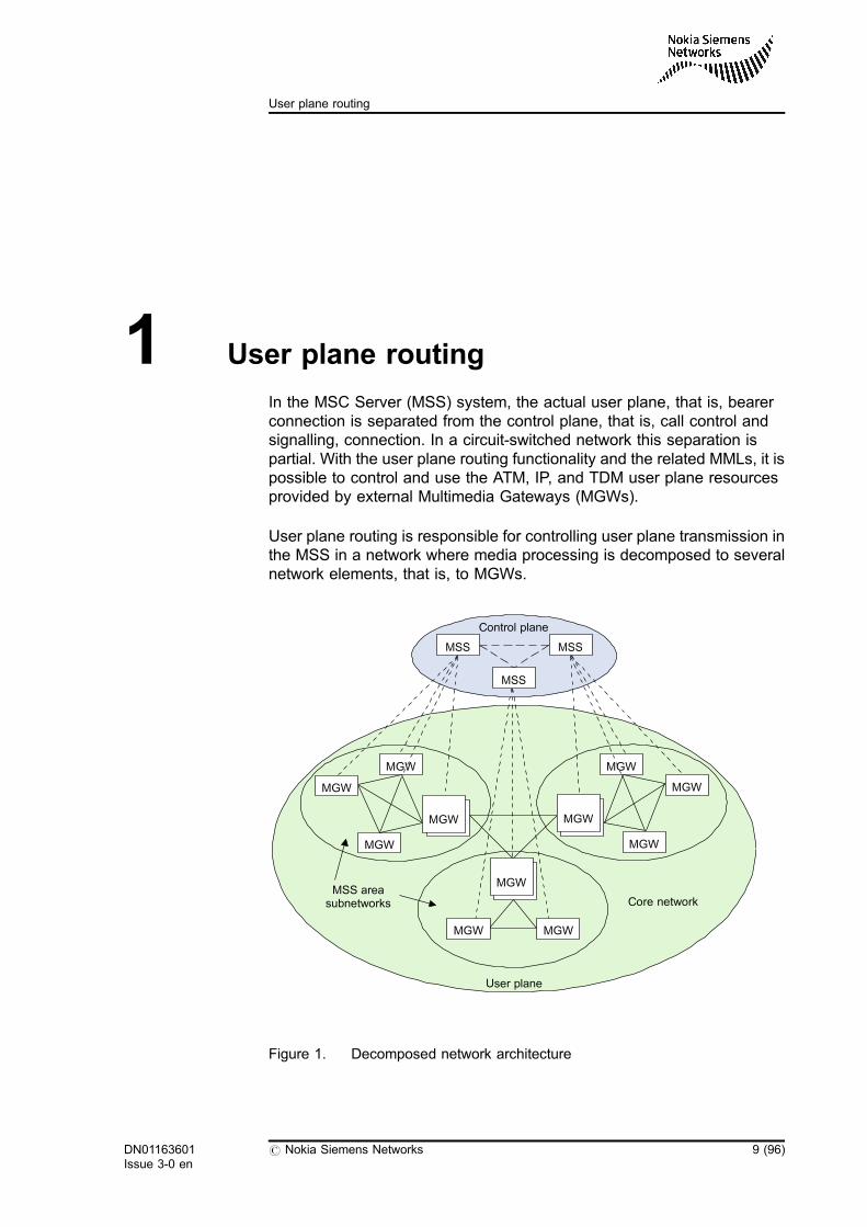
In the MSC Server (MSS) system, the actual user plane, that is, bearerconnection is separated from the control plane, that is, call control andsignalling, connection. In a circuit-switched network this separation ispartial. With the user plane routing functionality and the related MMLs, it ispossible to control and use the ATM, IP, and TDM user plane resourcesprovided by external Multimedia Gateways (MGWs).
User plane routing is responsible for controlling user plane transmission inthe MSS in a network where media processing is decomposed to severalnetwork elements, that is, to MGWs.
Figure 1. Decomposed network architecture
Control plane
MGW
MGW MGW
MGW
MGWMSS area
subnetworks Core network
User plane
MSSMSS
MGWMGW
MSS
MGW
MGW
MGW
MGW
DN01163601Issue 3-0 en
# Nokia Siemens Networks 9 (96)
User plane routing
These sections cover only the basic functionality of user plane routing. Therelated procedures are available in User Plane Routing, Operatinginstructions.
10 (96) # Nokia Siemens Networks DN01163601Issue 3-0 en
User Plane Routing
2 Call cases for user plane routing
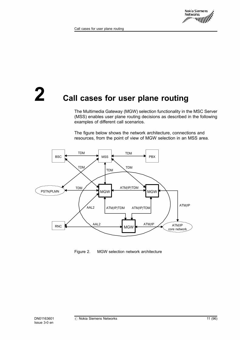
The Multimedia Gateway (MGW) selection functionality in the MSC Server(MSS) enables user plane routing decisions as described in the followingexamples of different call scenarios.
The figure below shows the network architecture, connections andresources, from the point of view of MGW selection in an MSS area.
Figure 2. MGW selection network architecture
AAL2 ATM/IP
TDM
TDM
TDM
TDMTDM
ATM/IP
ATM/IP/TDM
AAL2
MGWMGW
BSC
PSTN/PLMN
RNC ATM/IPcore network
PBXMSSTDM
ATM/IP/TDM ATM/IP/TDM
MGW
DN01163601Issue 3-0 en
# Nokia Siemens Networks 11 (96)
Call cases for user plane routing
Note
ATM/IP (ephemeral resources that are hunted by the MGW) can be thefollowing:
. ATM AAL2
. IPv4
. IPv6
The physical resources located in the MGW are hunted by the MSS.
TDM to ATM/IP
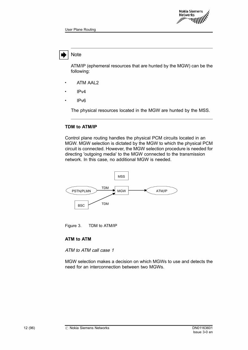
Control plane routing handles the physical PCM circuits located in anMGW. MGW selection is dictated by the MGW to which the physical PCMcircuit is connected. However, the MGW selection procedure is needed fordirecting 'outgoing media' to the MGW connected to the transmissionnetwork. In this case, no additional MGW is needed.
Figure 3. TDM to ATM/IP
ATM to ATM
ATM to ATM call case 1
MGW selection makes a decision on which MGWs to use and detects theneed for an interconnection between two MGWs.
MSS
TDM
TDM
PSTN/PLMN
BSC
MGW ATM/IP
12 (96) # Nokia Siemens Networks DN01163601Issue 3-0 en
User Plane Routing
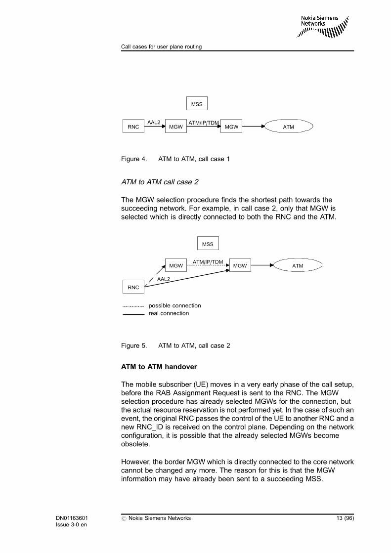
Figure 4. ATM to ATM, call case 1
ATM to ATM call case 2
The MGW selection procedure finds the shortest path towards thesucceeding network. For example, in call case 2, only that MGW isselected which is directly connected to both the RNC and the ATM.
Figure 5. ATM to ATM, call case 2
ATM to ATM handover
The mobile subscriber (UE) moves in a very early phase of the call setup,before the RAB Assignment Request is sent to the RNC. The MGWselection procedure has already selected MGWs for the connection, butthe actual resource reservation is not performed yet. In the case of such anevent, the original RNC passes the control of the UE to another RNC and anew RNC_ID is received on the control plane. Depending on the networkconfiguration, it is possible that the already selected MGWs becomeobsolete.
However, the border MGW which is directly connected to the core networkcannot be changed any more. The reason for this is that the MGWinformation may have already been sent to a succeeding MSS.
MSS
AAL2 ATM/IP/TDMRNC MGW MGW ATM
MSS
AAL2
ATM/IP/TDM
RNC
MGW MGW ATM
possible connection
real connection
DN01163601Issue 3-0 en
# Nokia Siemens Networks 13 (96)
Call cases for user plane routing

ATM to ATM call case 3
In this case MGW selection adapts to this changed situation by selecting anew MGW for an interconnection between the new RNC and the MGWconnected to the core network.
Figure 6. ATM to ATM, call case 3
ATM to ATM call case 4
In this case the MGW selection procedure determines that the new RNCalso has a connection to the same, previously selected, border MGW, andthus, no interconnecting MGW is needed.
Figure 7. ATM to ATM, call case 4
ATM to ATM call case 5
MSS
AAL2ATM/IP/TDM
AAL2
MGWRNC
MGW ATM
MGWRNCATM/IP/TDM
MSS
AAL2
MGW
MGW
MGW ATM
RNC
RNC
14 (96) # Nokia Siemens Networks DN01163601Issue 3-0 en
User Plane Routing
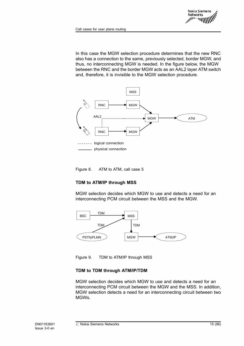
In this case the MGW selection procedure determines that the new RNCalso has a connection to the same, previously selected, border MGW, andthus, no interconnecting MGW is needed. In the figure below, the MGWbetween the RNC and the border MGW acts as an AAL2 layer ATM switchand, therefore, it is invisible to the MGW selection procedure.
Figure 8. ATM to ATM, call case 5
TDM to ATM/IP through MSS
MGW selection decides which MGW to use and detects a need for aninterconnecting PCM circuit between the MSS and the MGW.
Figure 9. TDM to ATM/IP through MSS
TDM to TDM through ATM/IP/TDM
MGW selection decides which MGW to use and detects a need for aninterconnecting PCM circuit between the MGW and the MSS. In addition,MGW selection detects a need for an interconnecting circuit between twoMGWs.
MSS
AAL2
RNC
ATM
RNC MGW
MGW
MGW
logical connection
physical connection
TDM
TDM
TDM
BSC MSS
PSTN/PLMN MGW ATM/IP
DN01163601Issue 3-0 en
# Nokia Siemens Networks 15 (96)
Call cases for user plane routing
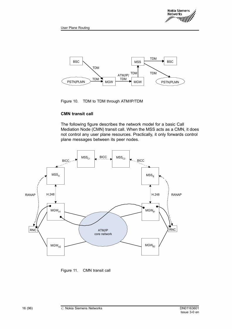
Figure 10. TDM to TDM through ATM/IP/TDM
CMN transit call
The following figure describes the network model for a basic CallMediation Node (CMN) transit call. When the MSS acts as a CMN, it doesnot control any user plane resources. Practically, it only forwards controlplane messages between its peer nodes.
Figure 11. CMN transit call
TDM
TDM
TDMTDM
TDM
ATM/IP/TDM
BSC
PSTN/PLMN MGW MGW
MSS BSC
PSTN/PLMN
MSSB
MGWA1
MSSA
MGWB1
RNC
RANAP H.248 H.248
BICC
ATM/IPcore network
RNC
MSSC1BICC
RANAP
MGWA2MGWB2
MSSC2BICC
16 (96) # Nokia Siemens Networks DN01163601Issue 3-0 en
User Plane Routing
For example, a transit level MSS, acting as a Transit MSC (TMSC) orGateway MSC (GMSC), can operate in CMN mode. CMN mode operationis possible if no user plane resource is required by the MSS and therequired type of user plane connection exists between the preceding andthe succeeding nodes. Based on its configuration data, the MSS is able todetermine during the call processing whether it should act as a CMN or aTransit Serving Node (TSN).
DN01163601Issue 3-0 en
# Nokia Siemens Networks 17 (96)
Call cases for user plane routing

18 (96) # Nokia Siemens Networks DN01163601Issue 3-0 en
User Plane Routing
3 Control plane signallings in MSC Server
Bearer establishment can be achieved with the following signallingprotocols:
. BICC
. SIP
. RANAP
For more detailed information about the signalling protocols and the bearerestablishment-related functionality, see the feature descriptions of thefollowing features:
. Feature 1325: RANAP and BSSAP in MSC Server
. Feature 1327: Basic Call Cases in MSC Server
. Feature 1330: Bearer Independent Call Control (BICC)
. Feature 1331: Session Initiation Protocol in the MSC Server
. Feature 1335: Speech Transmission Optimisation in MSC Server
DN01163601Issue 3-0 en
# Nokia Siemens Networks 19 (96)
Control plane signallings in MSC Server

20 (96) # Nokia Siemens Networks DN01163601Issue 3-0 en
User Plane Routing
4 User plane analysis
4.1 User plane analysis architecture
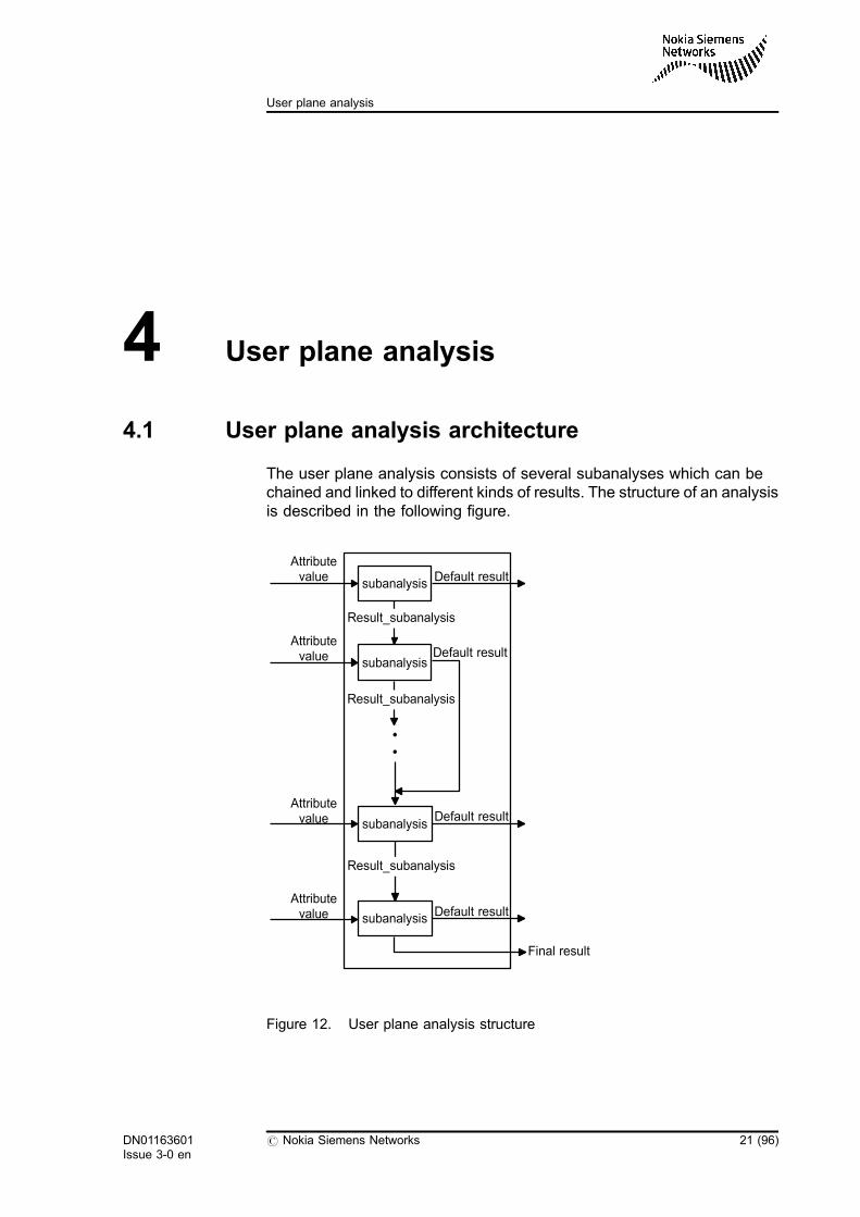
The user plane analysis consists of several subanalyses which can bechained and linked to different kinds of results. The structure of an analysisis described in the following figure.
Figure 12. User plane analysis structure
subanalysis
subanalysis
Result_subanalysis
Attributevalue Default result
subanalysis
subanalysis
Result_subanalysis
Result_subanalysis
Default result
Final result
Default result
Default result
Attributevalue
Attributevalue
Attributevalue
DN01163601Issue 3-0 en
# Nokia Siemens Networks 21 (96)
User plane analysis
The user plane analysis, like the extended preanalysis and the attributeanalysis, has attributes to be analysed. Each attribute can be analysed inone or more subanalyses, and the subanalyses can be chained.
The attribute is a call-related variable. The value of the attribute is thevalue of the variable. In a subanalysis, there can be only one attribute, butthe handling of the different values of this attribute varies. For example, theanalysis may continue from the next subanalysis with one attribute value,but may go to the final result with another value.
Starting and continuation subanalyses
The starting subanalysis is a subanalysis from which the execution of theanalysis chain starts. All the other subanalyses are continuationsubanalyses. Each subanalysis includes the following:
. A common part which includes the name of the subanalysis and anattribute identifier of the attribute to be analysed. A unique name isdefined for every subanalysis and reference from one subanalysis tothe next is made using this name.
. A part for normal traffic in which the subanalyses are for normaltraffic and which is called normal side.
. A part for test traffic in which the subanalyses are for test traffic andwhich is called test side.
Normal and test sides of a subanalysis
The normal side includes the following information:
. the starting point for the analysis of the attribute values
. a default result
. an unknown result
The structure of the test side is similar to the structure of the normal side.
Note
The test side can have its own analysis for attribute values, the defaultresult, and the unknown result.
22 (96) # Nokia Siemens Networks DN01163601Issue 3-0 en
User Plane Routing
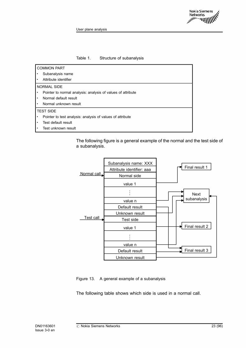
Table 1. Structure of subanalysis
COMMON PART. Subanalysis name. Attribute identifier
NORMAL SIDE. Pointer to normal analysis: analysis of values of attribute. Normal default result. Normal unknown result
TEST SIDE. Pointer to test analysis: analysis of values of attribute. Test default result. Test unknown result
The following figure is a general example of the normal and the test side ofa subanalysis.
Figure 13. A general example of a subanalysis
The following table shows which side is used in a normal call.
Subanalysis name: XXX
Attribute identifier: aaa
Normal side
value 1
value n
Default result
Unknown result
Test side
value 1
value n
Default result
Unknown result
.
..
.
..
Final result 1
Final result 2
Final result 3
Nextsubanalysis
Normal call
Test call
DN01163601Issue 3-0 en
# Nokia Siemens Networks 23 (96)
User plane analysis
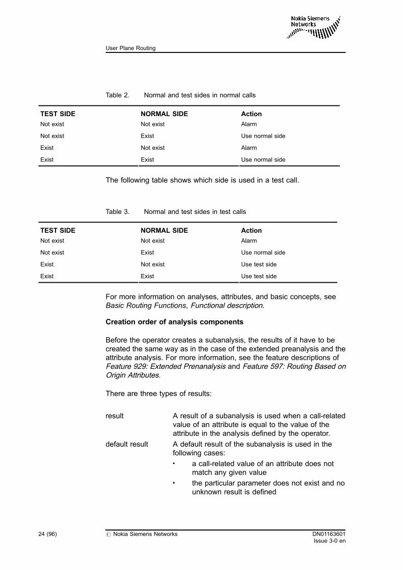
Table 2. Normal and test sides in normal calls
TEST SIDE NORMAL SIDE Action
Not exist Not exist Alarm
Not exist Exist Use normal side
Exist Not exist Alarm
Exist Exist Use normal side
The following table shows which side is used in a test call.
Table 3. Normal and test sides in test calls
TEST SIDE NORMAL SIDE Action
Not exist Not exist Alarm
Not exist Exist Use normal side
Exist Not exist Use test side
Exist Exist Use test side
For more information on analyses, attributes, and basic concepts, seeBasic Routing Functions, Functional description.
Creation order of analysis components
Before the operator creates a subanalysis, the results of it have to becreated the same way as in the case of the extended preanalysis and theattribute analysis. For more information, see the feature descriptions ofFeature 929: Extended Prenanalysis and Feature 597: Routing Based onOrigin Attributes.
There are three types of results:
result A result of a subanalysis is used when a call-relatedvalue of an attribute is equal to the value of theattribute in the analysis defined by the operator.
default result A default result of the subanalysis is used in thefollowing cases:. a call-related value of an attribute does not
match any given value. the particular parameter does not exist and no
unknown result is defined
24 (96) # Nokia Siemens Networks DN01163601Issue 3-0 en
User Plane Routing
unknown result An unknown result is used when a call-related valueof an attribute does not exist. For example, if theattribute is valid only when the patricular call is amobile-originated or PBX-originated call. In the caseof a trunk-originated call, the value is not determined.That is why the unknown result gives instructions onhow to continue if the attribute value does not exist.
A subanalysis must have both a result and a default result, which aredefined by their names. The operator can also create an unknown resultfor a subanalysis, however, this is not mandatory. If no unknown result isdefined by the operator, the default result is used as the unknown result.After creating the results, the operator can create the subanalysis.
The creation, modification, and deletion principles for the user planeanalysis are similar to the rules which apply for the extended preanalysis.For more information, see the command descriptions of ExtendedPreanalysis Handling, CW command group and User Plane AnalysisHandling, JU command group.
After creating the subanalysis, only the test side of the subanalysis existsuntil the operator changes the state of the subanalysis. The creation andthe modification concern only the test side. A prerequisite for themodification of the subanalysis is the existence of the test side.
For more information on how to create or modify subanalyses and finalresults, see Section Configuring user plane analysis in User PlaneRouting, Operating instructions.
Testing and state changes
The operator can test the functionality of the user plane analysis with thehelp of test traffic. If the analysis functions as desired, the operator canchange the side of the subanalysis. This means that subanalysis data ismoved from test side to normal side, that is, only the normal side of thesubanalysis exists afterwards. The test side of the subanalysis is deletedbecause the test traffic uses the normal side of the subanalysis if no testside exists.
For instructions and a description on the use of test calls, see Test CallHandling, YC command group and Feature 215: Test Call and DigitAnalysis Test State, Feature description.
DN01163601Issue 3-0 en
# Nokia Siemens Networks 25 (96)
User plane analysis
Changing the state of the subanalysis from normal side to test side doesnot transfer the data on the normal side to the test side: it only makes acopy of it. This way the normal traffic still uses the normal side of thesubanalysis and the operator can modify the test side of the subanalysiswith MML commands. The modifications can be tested safely in a livenetwork with the help of Feature 215: Test Call and Digit Analysis TestState.
4.2 User plane analysis phases
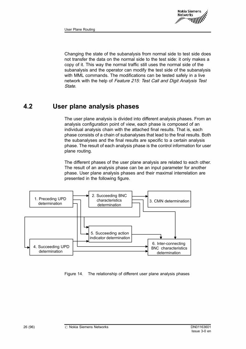
The user plane analysis is divided into different analysis phases. From ananalysis configuration point of view, each phase is composed of anindividual analysis chain with the attached final results. That is, eachphase consists of a chain of subanalyses that lead to the final results. Boththe subanalyses and the final results are specific to a certain analysisphase. The result of each analysis phase is the control information for userplane routing.
The different phases of the user plane analysis are related to each other.The result of an analysis phase can be an input parameter for anotherphase. User plane analysis phases and their maximal interrelation arepresented in the following figure.
Figure 14. The relationship of different user plane analysis phases
6. Inter-connectingBNC characteristics
determination
4. Succeeding UPDdetermination
2. Succeeding BNCcharacteristicsdetermination
1. Preceding UPDdetermination
5. Succeeding actionindicator determination
3. CMN determination
26 (96) # Nokia Siemens Networks DN01163601Issue 3-0 en
User Plane Routing
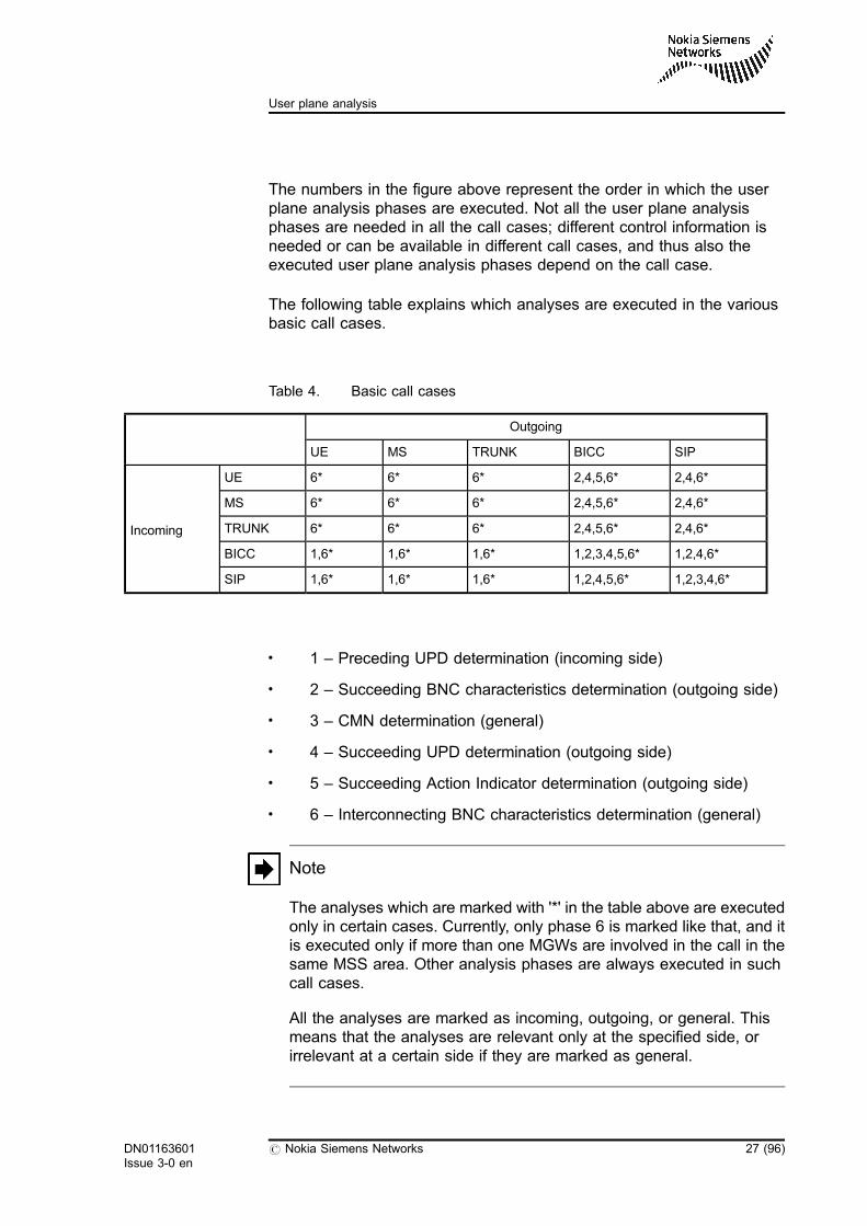
The numbers in the figure above represent the order in which the userplane analysis phases are executed. Not all the user plane analysisphases are needed in all the call cases; different control information isneeded or can be available in different call cases, and thus also theexecuted user plane analysis phases depend on the call case.
The following table explains which analyses are executed in the variousbasic call cases.
Table 4. Basic call cases
Outgoing
UE MS TRUNK BICC SIP
Incoming
UE 6* 6* 6* 2,4,5,6* 2,4,6*
MS 6* 6* 6* 2,4,5,6* 2,4,6*
TRUNK 6* 6* 6* 2,4,5,6* 2,4,6*
BICC 1,6* 1,6* 1,6* 1,2,3,4,5,6* 1,2,4,6*
SIP 1,6* 1,6* 1,6* 1,2,4,5,6* 1,2,3,4,6*
. 1 – Preceding UPD determination (incoming side)
. 2 – Succeeding BNC characteristics determination (outgoing side)
. 3 – CMN determination (general)
. 4 – Succeeding UPD determination (outgoing side)
. 5 – Succeeding Action Indicator determination (outgoing side)
. 6 – Interconnecting BNC characteristics determination (general)
Note
The analyses which are marked with '*' in the table above are executedonly in certain cases. Currently, only phase 6 is marked like that, and itis executed only if more than one MGWs are involved in the call in thesame MSS area. Other analysis phases are always executed in suchcall cases.
All the analyses are marked as incoming, outgoing, or general. Thismeans that the analyses are relevant only at the specified side, orirrelevant at a certain side if they are marked as general.
DN01163601Issue 3-0 en
# Nokia Siemens Networks 27 (96)
User plane analysis
There are a few special cases when analyses are executed also afterbasic call setup procedures:
. When call forwarding takes place, all the outgoing side analyses areexecuted again which are relevant to the signalling type on which thenew leg is established. Also phase 6 can be executed againdepending on the number of MGWs.
An addition to this rule is when the incoming side is BICC/SIP andthe same signalling type is used in establishing the forwarded leg.Phase 3 (CMN determination) is also executed again.
For example, if there is a UE-MS call where the MS does not replyand the call is forwarded to the BICC core network, the analysesphases 2, 4, 5, and 6* are executed.
. In inter-MSS handover both the incoming and the outgoing sidesubscribers can handover to different MSS areas. However,independent of the initiating side, in such cases, the succeedingdeterminations, phases 2, 4, and 5 for BICC and phases 2 and 4 forSIP, are always executed. Phase 1, on the other hand, is neverexecuted. This means that when establishing a new core networkconnection, outgoing analyses are executed. As a difference to callforwarding, phase 3 is never executed in inter-MSS handover cases.However, phase 6* can still be executed if there is a new MGW forthe handover leg establishment.
For example, in a UE-MS call, the UE (incoming subscriber) makes ahandover to a different MSS area. The used signalling between theMSSs is BICC. Only outgoing side analyses are executed, that is,phases 2, 4, and 5. If there is a need for an additional MGW withinterconnection, phase 6* is also executed.
The following overview to the different user plane analysis phases showsthe available attributes and results. The attributes that are obligatory for asuccessful analysis in the specific phase are marked with (*).
Phase 1: 'Preceding UPD determination'
This phase is executed only if the incoming signalling is BICC or SIP. InUE-originating calls the UPD is defined in the radio network configurationdata. In any other call cases this phase has no significance because noincoming UPD exists. For example, in the case of TDM resources thecircuit also identifies the MGW and UPD is not needed.
The available attributes in this phase are the following:
28 (96) # Nokia Siemens Networks DN01163601Issue 3-0 en
User Plane Routing
. Emergency call indicator
. Original dialling class
. Preceding action indicator
. Preceding BCU-ID
. Preceding BNC characteristics
. Preceding signalling type
. Preceding UPDR (*)
. User plane bearer requirement
The result of this phase is the following:
. Preceding User Plane Destination, UPD
Phase 2: 'Succeeding BNC characteristics determination'
This phase is needed to figure out the bearer technology used towards thesucceeding MGW. This phase is executed only if the outgoing signalling isBICC or SIP. In any other call cases this phase has no significance; inthese cases there is only one available bearer technology that is dictatedby the interface. For example, in UE terminating cases only ATM AAL2 canbe used on the Iu-CS interface.
The available attributes in this phase are the following:
. Emergency call indicator
. Inter-MSS handover indicator
. Original dialling class
. Preceding action indicator
. Preceding BCU-ID
. Preceding BNC characteristics
. Preceding signalling type
. Preceding UPDR
. Preceding user plane destination, UPD (from phase 1 if it exists)
. Succeeding signalling type
. Succeeding UPDR
. User plane bearer requirement
DN01163601Issue 3-0 en
# Nokia Siemens Networks 29 (96)
User plane analysis
The result of this phase is the following:
. Succeeding BNC characteristics
Phase 3: 'CMN determination'
This phase is used to detect whether an MSS should act as a CMN node.This phase is executed only if the incoming and outgoing signalling are thesame, either BICC or SIP, and no resource has been reserved from theMGW yet. CMN mode operation is possible only in these cases.
The available attributes in this phase are the following:
. OLCM usage indicator
. Original dialling class
. Preceding BNC characteristics
. Preceding signalling type
. Preceding UPDR (*)
. Succeeding BNC characteristics (from phase 2)
. Succeeding signalling type
. Succeeding UPDR (*)
The result of this phase is the following:
. CMN indicator
Phase 4: 'Succeeding UPD determination'
This phase is executed only if the outgoing signalling is BICC or SIP. InUE-terminating calls the UPD is defined in the radio network configurationdata. In any other call cases this phase has no significance because inthose cases no outgoing UPD exists.
The available attributes in this phase are the following:
. Emergency call indicator
. Original dialling class
. Preceding action indicator
. Preceding BCU-ID
. Preceding UPDR
30 (96) # Nokia Siemens Networks DN01163601Issue 3-0 en
User Plane Routing
. Succeeding BCU-ID
This parameter is valid only in the case of delayed MGW selection. Itcan be received from the succeeding MSS in APM.
. Succeeding BNC characteristics (from phase 2)
. Succeeding signalling type
. Succeeding UPDR (*)
. User plane bearer requirement
The result of this phase is the following:
. Succeeding user plane destination, UPD
Phase 5: 'Succeeding action indicator determination'
This phase is executed only if the outgoing signalling is BICC. The actionindicator is specific to BICC call control signalling. It controls the usedBICC bearer establishment method.
The available attributes in this phase are the following:
. Emergency call indicator
. Inter-MSS handover indicator
. Original dialling class
. Preceding action indicator
. Preceding BCU-ID
. Preceding BNC characteristics
. Preceding signalling type
. Preceding UPDR
. Preceding user plane destination, UPD (from phase 1 if it exists)
. Succeeding BNC characteristics (from phase 2)
. Succeeding signalling type
. Succeeding UPDR
. Succeeding user plane destination, UPD (from phase 4)
. User plane bearer requirement
DN01163601Issue 3-0 en
# Nokia Siemens Networks 31 (96)
User plane analysis
The result of this phase is the following:
. Succeeding action indicator
Phase 6: 'Interconnecting BNC characteristics determination'
This phase is executed when there are two MGWs involved in a call in oneMSS area and an interconnection is needed between the two MGWs. If theIC_CONF_OPT_IN_PHYS_MGW PRFILE parameter is active and the twoselected MGWs are in the same physical MGW, the 'Interconnecting BNCcharacteristics determination' phase is skipped.
The available attributes in this phase are the following:
. Emergency call indicator
. Original dialling class
. Preceding action indicator
. Preceding BNC characteristics
. Preceding signalling type
. Preceding UPDR
. Preceding user plane destination, UPD (from phase 1 if it exists)
. Succeeding action indicator (from phase 5 if it exists)
. Succeeding BNC characteristics (from phase 2 if it exists)
. Succeeding signalling type
. Succeeding UPDR
. Succeeding user plane destination, UPD (from phase 4 if it exists)
. User plane bearer requirement
The result of this phase is the following:
. Interconnecting BNC characteristics
For more information, see Section Configuring user plane analysis in UserPlane Routing, Operating instructions.
32 (96) # Nokia Siemens Networks DN01163601Issue 3-0 en
User Plane Routing
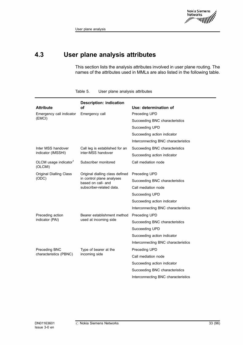
4.3 User plane analysis attributes
This section lists the analysis attributes involved in user plane routing. Thenames of the attributes used in MMLs are also listed in the following table.
Table 5. User plane analysis attributes
AttributeDescription: indicationof Use: determination of
Emergency call indicator(EMCI)
Emergency call Preceding UPD
Succeeding BNC characteristics
Succeeding UPD
Succeeding action indicator
Interconnecting BNC characteristics
Inter MSS handoverindicator (IMSSHI)
Call leg is established for aninter-MSS handover
Succeeding BNC characteristics
Succeeding action indicator
OLCM usage indicator1
(OLCMI)Subscriber monitored Call mediation node
Original Dialling Class(ODC)
Original dialling class definedin control plane analysesbased on call- andsubscriber-related data.
Preceding UPD
Succeeding BNC characteristics
Call mediation node
Succeeding UPD
Succeeding action indicator
Interconnecting BNC characteristics
Preceding actionindicator (PAI)
Bearer establishment methodused at incoming side
Preceding UPD
Succeeding BNC characteristics
Succeeding UPD
Succeeding action indicator
Interconnecting BNC characteristics
Preceding BNCcharacteristics (PBNC)
Type of bearer at theincoming side
Preceding UPD
Call mediation node
Succeeding action indicator
Succeeding BNC characteristics
Interconnecting BNC characteristics
DN01163601Issue 3-0 en
# Nokia Siemens Networks 33 (96)
User plane analysis
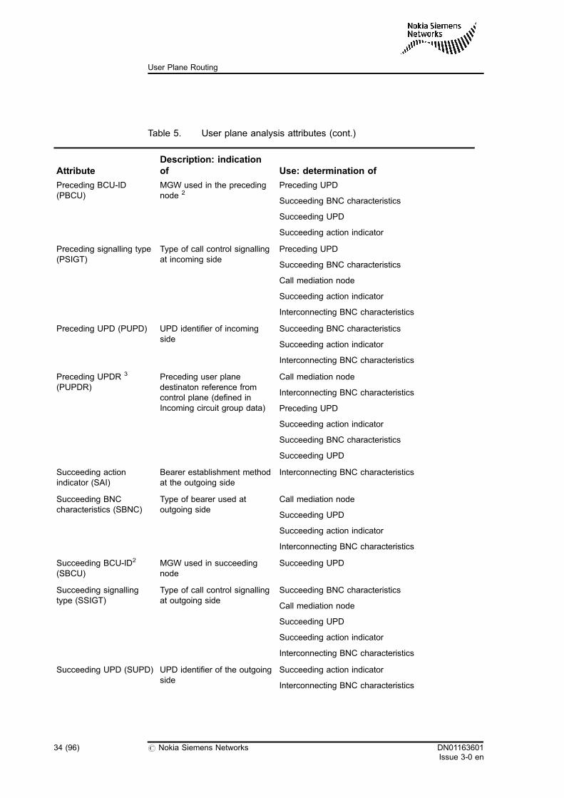
Table 5. User plane analysis attributes (cont.)
AttributeDescription: indicationof Use: determination of
Preceding BCU-ID(PBCU)
MGW used in the precedingnode 2
Preceding UPD
Succeeding BNC characteristics
Succeeding UPD
Succeeding action indicator
Preceding signalling type(PSIGT)
Type of call control signallingat incoming side
Preceding UPD
Succeeding BNC characteristics
Call mediation node
Succeeding action indicator
Interconnecting BNC characteristics
Preceding UPD (PUPD) UPD identifier of incomingside
Succeeding BNC characteristics
Succeeding action indicator
Interconnecting BNC characteristics
Preceding UPDR 3
(PUPDR)Preceding user planedestinaton reference fromcontrol plane (defined inIncoming circuit group data)
Call mediation node
Interconnecting BNC characteristics
Preceding UPD
Succeeding action indicator
Succeeding BNC characteristics
Succeeding UPD
Succeeding actionindicator (SAI)
Bearer establishment methodat the outgoing side
Interconnecting BNC characteristics
Succeeding BNCcharacteristics (SBNC)
Type of bearer used atoutgoing side
Call mediation node
Succeeding UPD
Succeeding action indicator
Interconnecting BNC characteristics
Succeeding BCU-ID2
(SBCU)MGW used in succeedingnode
Succeeding UPD
Succeeding signallingtype (SSIGT)
Type of call control signallingat outgoing side
Succeeding BNC characteristics
Call mediation node
Succeeding UPD
Succeeding action indicator
Interconnecting BNC characteristics
Succeeding UPD (SUPD) UPD identifier of the outgoingside
Succeeding action indicator
Interconnecting BNC characteristics
34 (96) # Nokia Siemens Networks DN01163601Issue 3-0 en
User Plane Routing
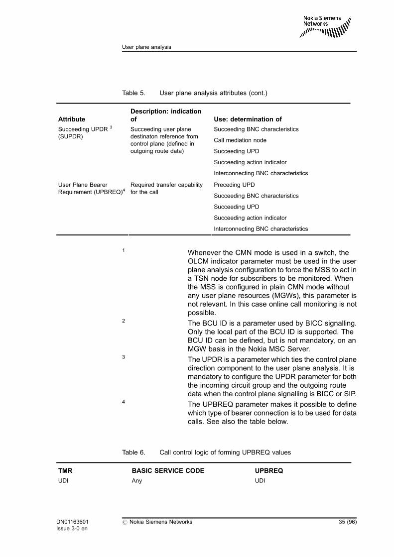
Table 5. User plane analysis attributes (cont.)
AttributeDescription: indicationof Use: determination of
Succeeding UPDR 3
(SUPDR)Succeeding user planedestinaton reference fromcontrol plane (defined inoutgoing route data)
Succeeding BNC characteristics
Call mediation node
Succeeding UPD
Succeeding action indicator
Interconnecting BNC characteristics
User Plane BearerRequirement (UPBREQ)4
Required transfer capabilityfor the call
Preceding UPD
Succeeding BNC characteristics
Succeeding UPD
Succeeding action indicator
Interconnecting BNC characteristics
1 Whenever the CMN mode is used in a switch, theOLCM indicator parameter must be used in the userplane analysis configuration to force the MSS to act ina TSN node for subscribers to be monitored. Whenthe MSS is configured in plain CMN mode withoutany user plane resources (MGWs), this parameter isnot relevant. In this case online call monitoring is notpossible.
2 The BCU ID is a parameter used by BICC signalling.Only the local part of the BCU ID is supported. TheBCU ID can be defined, but is not mandatory, on anMGW basis in the Nokia MSC Server.
3 The UPDR is a parameter which ties the control planedirection component to the user plane analysis. It ismandatory to configure the UPDR parameter for boththe incoming circuit group and the outgoing routedata when the control plane signalling is BICC or SIP.
4 The UPBREQ parameter makes it possible to definewhich type of bearer connection is to be used for datacalls. See also the table below.
Table 6. Call control logic of forming UPBREQ values
TMR BASIC SERVICE CODE UPBREQ
UDI Any UDI
DN01163601Issue 3-0 en
# Nokia Siemens Networks 35 (96)
User plane analysis
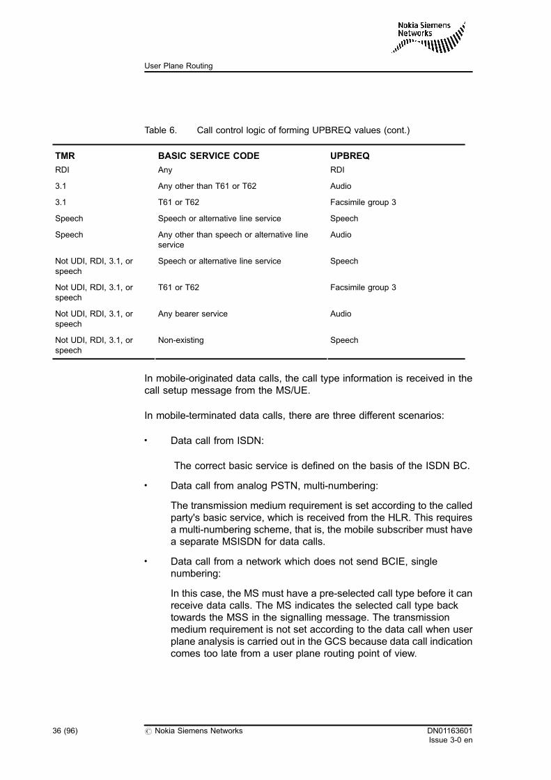
Table 6. Call control logic of forming UPBREQ values (cont.)
TMR BASIC SERVICE CODE UPBREQ
RDI Any RDI
3.1 Any other than T61 or T62 Audio
3.1 T61 or T62 Facsimile group 3
Speech Speech or alternative line service Speech
Speech Any other than speech or alternative lineservice
Audio
Not UDI, RDI, 3.1, orspeech
Speech or alternative line service Speech
Not UDI, RDI, 3.1, orspeech
T61 or T62 Facsimile group 3
Not UDI, RDI, 3.1, orspeech
Any bearer service Audio
Not UDI, RDI, 3.1, orspeech
Non-existing Speech
In mobile-originated data calls, the call type information is received in thecall setup message from the MS/UE.
In mobile-terminated data calls, there are three different scenarios:
. Data call from ISDN:
The correct basic service is defined on the basis of the ISDN BC.
. Data call from analog PSTN, multi-numbering:
The transmission medium requirement is set according to the calledparty's basic service, which is received from the HLR. This requiresa multi-numbering scheme, that is, the mobile subscriber must havea separate MSISDN for data calls.
. Data call from a network which does not send BCIE, singlenumbering:
In this case, the MS must have a pre-selected call type before it canreceive data calls. The MS indicates the selected call type backtowards the MSS in the signalling message. The transmissionmedium requirement is not set according to the data call when userplane analysis is carried out in the GCS because data call indicationcomes too late from a user plane routing point of view.
36 (96) # Nokia Siemens Networks DN01163601Issue 3-0 en
User Plane Routing
For more information, see Configuring user plane analysis in User PlaneRouting, Operating instructions.
4.4 User plane analysis results
The result of the user plane analysis can be one of the following:
Table 7. Possible results of the user plane analysis
Analysis Results
Call mediation node Indicates whether the MSC Server must act as a TSNor as a CMN node.
Interconnecting backbone network connectioncharacteristics
Indicates what type of bearer is used between twoMGWs controlled by one MSC Server.
Preceding user plane destination Identifies the user plane destination for the incomingside.
Succeeding action indicator Indicates what bearer establishment method is usedat the outgoing side.
Succeeding backbone network connectioncharacteristics
Indicates what type of bearer is used at the outgoingside.
Succeeding user plane destination Identifies the user plane destination for the outgoingside.
The following figure describes the relationship between the analysisresults:
DN01163601Issue 3-0 en
# Nokia Siemens Networks 37 (96)
User plane analysis
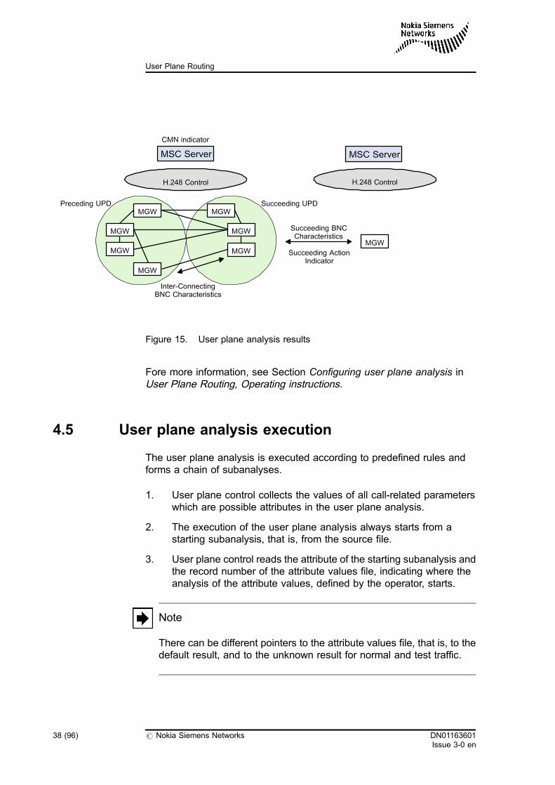
Figure 15. User plane analysis results
Fore more information, see Section Configuring user plane analysis inUser Plane Routing, Operating instructions.
4.5 User plane analysis execution
The user plane analysis is executed according to predefined rules andforms a chain of subanalyses.
1. User plane control collects the values of all call-related parameterswhich are possible attributes in the user plane analysis.
2. The execution of the user plane analysis always starts from astarting subanalysis, that is, from the source file.
3. User plane control reads the attribute of the starting subanalysis andthe record number of the attribute values file, indicating where theanalysis of the attribute values, defined by the operator, starts.
Note
There can be different pointers to the attribute values file, that is, to thedefault result, and to the unknown result for normal and test traffic.
MSC Server
H.248 Control H.248 Control
MSC Server
MGW
MGW
MGW
MGW MGW
MGW
MGWPreceding UPD Succeeding UPD
Inter-ConnectingBNC Characteristics
MGW
Succeeding BNCCharacteristics
Succeeding ActionIndicator
CMN indicator
38 (96) # Nokia Siemens Networks DN01163601Issue 3-0 en
User Plane Routing
Test traffic-related data is in use only for test calls. Test traffic usesthe normal side data of the subanalysis if no separate test side datais available. Normal traffic never uses the test side data of thesubanalysis.
4. If no call case-related value of an attribute exists, there is nothing tobe analysed, thus continuation instructions are read immediatelyfrom the unknown result field of the subanalysis in the source file.
A call-related value of an attribute is analysed against the valuesdefined for the subanalysis by the operator. If they are the same, thatis, the call-related value of an attribute equals to the value defined inthe analysis, user plane control reads the continuation instructions,an indicator towards the next subanalysis or towards the final result,from the attribute values file. In this case, the analysis may eithercontinue from some other subanalysis in the source file or lead to afinal result in the result file.
If no match is found, that is, the call-related value of the attributediffers from those found in the analysis, user plane control reads thecontinuation instructions from the default result of the subanalysis inthe source file.
Note
Although in a subanalysis several values can be defined for oneattribute and all of them can have different results, that is, differentcontinuation instructions, there is only a single default result and asingle unknown result in each subanalysis. The default result cannot bethe same as any of the results of the attribute values.
5. When the analysis continues from the next subanalysis, user planecontrol reads the data of the subanalysis from the record of thesource file. An indicator is received from the attribute values fileshowing from where the subanalysis data must be read. Theanalysis continues in the same way as in the case of the startingsubanalysis. If a value of an attribute matches a predefined value ofthe subanalysis, the result of the subanalysis is either the nextsubanalysis or the final result.
If the result of the next subanalysis and the final result do no match,the result of the subanalysis is the default result, that is, an indicatoreither to another subanalysis or to the final result.
6. The analysis continues until a final result is reached. User planecontrol reads the result information and does the required actionwhen ordered by the analysis.
DN01163601Issue 3-0 en
# Nokia Siemens Networks 39 (96)
User plane analysis

40 (96) # Nokia Siemens Networks DN01163601Issue 3-0 en
User Plane Routing
5 User plane topology database
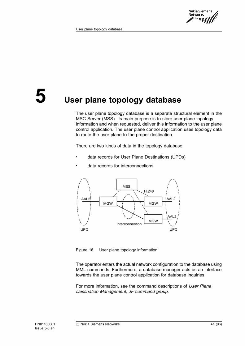
The user plane topology database is a separate structural element in theMSC Server (MSS). Its main purpose is to store user plane topologyinformation and when requested, deliver this information to the user planecontrol application. The user plane control application uses topology datato route the user plane to the proper destination.
There are two kinds of data in the topology database:
. data records for User Plane Destinations (UPDs)
. data records for interconnections
Figure 16. User plane topology information
The operator enters the actual network configuration to the database usingMML commands. Furthermore, a database manager acts as an interfacetowards the user plane control application for database inquiries.
For more information, see the command descriptions of User PlaneDestination Management, JF command group.
UPD
H.248
Interconnection
MGW
AAL2 AAL2
UPD
AAL2
MGW
MSS
MGW
DN01163601Issue 3-0 en
# Nokia Siemens Networks 41 (96)
User plane topology database
5.1 User plane destination
The UPD defines connections to (incoming side) and from (outgoing side)the MGWs controlled by an MSS. UPDs are created by the operator duringnetwork configuration. Physically, a UPD is a record in the topologydatabase. The number of UPDs stored in the database is limited to 1000.
From the point of view of an MSS, UPDs are a set of MGWs, which aregrouped based on certain criteria. Additionally, UPDs reflect the operator'sintention about the planned routing schemes. The typical grouping criteriaare BNC characteristics and IP trunk capability. UPDs can be overlapping.This means that different UPDs, where the grouping principle is different,can contain the same MGWs.
Grouping can be different not only based on BNC characteristics, but alsobased on the IP trunk capability indicator. If this parameter is set, and thefollowing conditions are fulfilled, call setup procedures are executeddifferently, which means that no Nb UP protocol is used and thepacketisation period for Nokia MGWs is 20 ms:
. signalling protocol is BICC, SIP-T, SIP-I, or 3GPP SIP
. bearer type is IP
. used speech codec is G.711 or the call is a data call
In other cases, the Nb UP framing protocol is used on the Nb interface andthe packetisation period for G.711 codec is 5 ms.
Note
The Nokia proprietary Nb' UP protocol is also supported for theinterconnecting IP bearer between two MGWs that are controlled by thesame MSS. The functionality can be activated with theNO_NBUP_ON_MGW_IC_LEG MSS-specific PRFILE parameter.
The Speech transmission optimisation method parameter is usedin the case of speech calls to peer core network elements. The parameterhas the following values:
. Codec negotiation
If this value is used, the MSS tries to perform codec negotiation inthe specified direction.
42 (96) # Nokia Siemens Networks DN01163601Issue 3-0 en
User Plane Routing
. Default codec
If this value is used, the MSS uses the UPD default codecparameter.
For more information, see Feature 1335: Speech TransmissionOptimisation in MSC Server, Feature description and Speech Codecs inMSC Server,Functional description.
Example Defining UPD1
UPD1 is defined with MGW1, MGW3, and MGW17. The bearer networkconnection type (BNC characteristics) is set to ATM AAL2. This meansthat when the call is routed through this UPD, only the above listed MGWscan be used in the given direction and the connection type is ATM AAL2.The Speech transmission optimisation method parameter is set tothe value 'codec negotiation'.
Example Defining UPD2
UPD2 is defined with MGW1 and MGW21. MGW1 is also included inUPD1. The bearer network connection type (BNC characteristics) is set toIPv4 in this case, so both selectable MGWs establish IPv4 connectionstowards the destination. The Speech transmission optimisationmethod parameter is set to the value 'codec negotiation'.
Example Defining UPD3
UPD3 is defined with the same MGWs as UPD2 but, in this case, thebearer network connection type (BNC characteristics) is set to IPv6. Thetrunk capability parameter is also set, which means that in call cases –where BICC, SIP-T, or SIP-I control plane signalling is used, the bearertype is IP, and the used codec is G.711 – no Nb UP framing protocol isused, and the packetisation period is 20 ms. The Speech transmissionoptimisation method parameter is set to the value 'default codec'.
The figure below shows an example of UPDs connected to neighbourMSSs. It is possible that several UPDs are used towards the samedestination.
DN01163601Issue 3-0 en
# Nokia Siemens Networks 43 (96)
User plane topology database
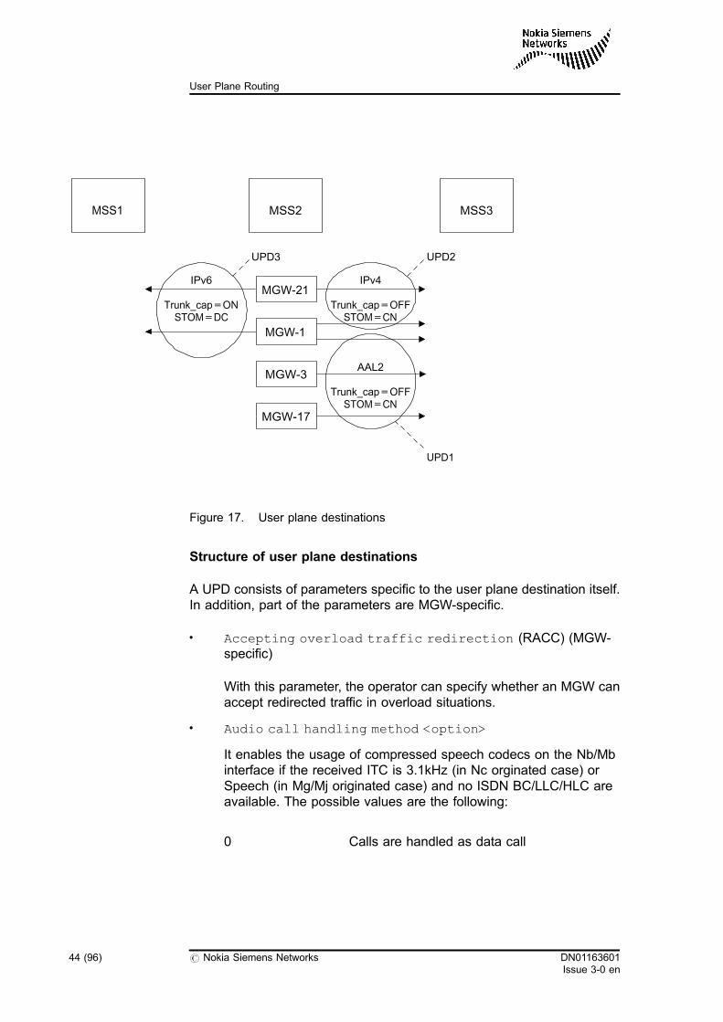
Figure 17. User plane destinations
Structure of user plane destinations
A UPD consists of parameters specific to the user plane destination itself.In addition, part of the parameters are MGW-specific.
. Accepting overload traffic redirection (RACC) (MGW-specific)
With this parameter, the operator can specify whether an MGW canaccept redirected traffic in overload situations.
. Audio call handling method <option>
It enables the usage of compressed speech codecs on the Nb/Mbinterface if the received ITC is 3.1kHz (in Nc orginated case) orSpeech (in Mg/Mj originated case) and no ISDN BC/LLC/HLC areavailable. The possible values are the following:
0 Calls are handled as data call
AAL2
Trunk_cap=OFFSTOM=CN
MSS2 MSS3
MGW-3
MGW-17
IPv4
Trunk_cap=OFFSTOM=CN
UPD2
UPD1
MGW-21
UPD3
IPv6
Trunk_cap=ONSTOM=DC
MSS1
MGW-1
44 (96) # Nokia Siemens Networks DN01163601Issue 3-0 en
User Plane Routing
1 Calls are handled as speech calls, ITC 3.1kHzis sent
2 Calls are handled as speech calls, ITC speechis sent
The default value is 0.
. Backbone network connection characteristics
With this parameter, the operator can define the Backbone NetworkConnection (BNC) characteristics of the UPD.
It indicates what type of bearer is used in the UPD (AAL2, IP, IPv4, orIPv6).
. Codec Modification Support <option>
With this parameter, the operator can set if codec modification canbe started or accepted to/from the specified direction.
. Default codec
It indicates the default codec used in the UPD if a more optimalcodec cannot be negotiated. The possible values are the following:. G.711. GSM EFR. GSM FR. UMTS AMR 2
Note
In inter-MSS call cases between two MSS domains, the default UPDcodec has an effect only on the Nb interface codec. The default codecused on the interconnecting leg between two MGWs controlled by thesame MSS can be set with the DEFAULT_IC_LEG_CODEC PRFILEparameter. The possible values of this parameter are the following:
. G.711
. GSM EFR
. GSM FR
. UMTS AMR 2
The DEFAULT_AMR_CODEC_MODE PRFILE parameter defines themode to be used with the AMR codec in the following cases:
. The default codec in the UPD is UMTS AMR 2.
. The interconnecting leg codec is specified as UMTS AMR 2with the DEFAULT_IC_LEG_CODEC parameter.
DN01163601Issue 3-0 en
# Nokia Siemens Networks 45 (96)
User plane topology database
The value of this parameter is only relevant in speech calls and inthe UPDs that are defined towards the peer core network elements,not in the UE codec selection in the UPDs that are defined towardsthe RNCs.
. Incoming bearer redirection allowance <option>
With this parameter, the operator can set if the incoming bearerredirection is allowed or not in the UPD.
. IPNWR
The operator can define the IP Network Reference Identifier (IPNWR)to be used in UPD.
IPNWR is used only if the MGW supports the nokiaipnwr H.248package. The parameter is valid only if the BNCC parameter is IPV4,IPV6, or IP.
. Load sharing index (MGW-specific)
Weight value for user plane traffic sharing between MGWs in a UPD.
. MGW identifiers list (MGW-specific)
It identifies the MGWs belonging to the UPD.
. MGW name (MGW-specific)
With this parameter, the operator can give the name of the MGWwhich the operator wants to add to the specified UPD.
. MGW re-selection provisioning status
It indicates the provisioning status of the MGW reselectionprocedure.
For more information, see Section User plane control level MGW re-selection.
This parameter can be set for both normal and emergency calls.
. Originating overload traffic redirection (RORIG)(MGW-specific)
With this parameter, the operator can specify whether overloadtraffic can be redirected from a congested MGW to other MGWsin congestion situations.
. Outgoing bearer redirection capability <option>
With this parameter, the operator can set the outgoing bearerredirection capability of the UPD.
. STOM <option>
46 (96) # Nokia Siemens Networks DN01163601Issue 3-0 en
User Plane Routing
With this parameter, the operator can set the Speech TransmissionOptimisation Method (STOM) of the UPD.
. Trunk capability <option>
With this parameter, the operator can set the ATM/IP trunk capabilityof the UPD. It indicates if the Nokia proprietary Nb' UP protocol canbe used.
. User plane destination index
Numerical identifier of the user plane destination.
. User plane destination name
Alphabetical identifier of the user plane destination.
For more information on codecs and on the Speech transmissionoptimisation method and Trunk capability parameters, seeSpeech Codecs in MSC Server, Functional description and Feature 1335:Speech Transmission Optimisation in MSC Server, Feature description.
For more information on the traffic redirection functionality, see SectionCongestion handling.
See also Section Configuring user plane topology database in User PlaneRouting, Operating instructions.
When fax or modem signal is detected the MSS system performs thecodec modification (from compressed codec to G.711 or clearmode codec)in order to enable the fax and modem data call.
For more information on UPD-specific parameters, see User PlaneTopology Data Handling, JF command group.
Codec preference list
When creating user plane destination, it is possible to set up UPD codecpreference list.
If UPD codec preference list contains at least one codec it will be used inthe following cases:
. UE originating call: UE supported codecs will be ordered accordingto the incoming UPD codec preference list.
. UE terminating call: UE supported codecs will be ordered accordingto the outgoing UPD codec preference list.
DN01163601Issue 3-0 en
# Nokia Siemens Networks 47 (96)
User plane topology database
. Creating supported codecs list (codec negotiation is initiated in theMSS): Priority order of the supported codecs list will be determinedaccording to the outgoing UPD codec preference list
. Transit cases: Incoming supported codecs list shall be restrictedaccording to the codecs in the incoming and outgoing UPD codecpreference list. Only the codec support is checked, priority orderdoes not matter.
. Network side codec selection (codec negotiation is terminating in theMSS). Only the codec support is checked in the incoming UPDcodec preference list, priority order does not matter.
The operator can create codec preference list with the JFF command.
For more information, see User Plane Topology Data Handling, JFCommand Group.
5.2 User plane topology between MGWs
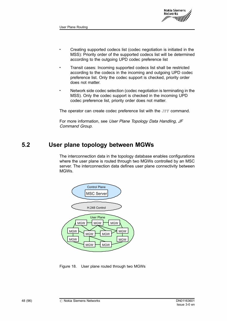
The interconnection data in the topology database enables configurationswhere the user plane is routed through two MGWs controlled by an MSCserver. The interconnection data defines user plane connectivity betweenMGWs.
Figure 18. User plane routed through two MGWs
MSC Server
Control Plane
MGW
MGW
MGW
MGW
MGW
MGWMGW
User Plane
MGW
MGW
MGW
MGW
H.248 Control
48 (96) # Nokia Siemens Networks DN01163601Issue 3-0 en
User Plane Routing
Structure of interconnection data
Interconnection data is organised on an MGW basis. For each MGW theinterconnection data consists of a list of interconnection data elements thatidentify existing interconnections from a particular MGW towards otherMGWs and an indication about full-meshed connectivity.
The relevant properties related to interconnections are the following:
. MGW identifier
It identifies the MGW in question which is connected to one orseveral other MGWs. The other MGWs are identified either by thefull-meshed connectivity or interconnection data.
. Full meshed connectivity
It indicates a fully-meshed configuration. The full-meshed indicationis MGW-specific and it means that the MGW has a connection to allother MGWs within the same MSS area with the given BNCcharacteristics. The possible interconnecting BNC characteristics inthe full-meshed configuration are ATM AAL2, IPv4, and IPv6. Thefull-meshed configuration can be supported with one or more BNCcharacteristics simultaneously.
. Interconnection data
Interconnection data defines interconnections towards one or moreother MGWs that are controlled by the same MSS. In addition toidentifying other MGWs, it also identifies what kind of bearerconnections exist to those MGWs by defining the available BNCcharacteristics. The possible interconnecting BNC characteristicsare ATM AAL2, IPv4, IPv6, and TDM. An interconnection cansupport one or more BNC characteristics simultaneously. In the caseof TDM interconnections, the interconnection data also identifies upto three interconnecting TDM routes between the MGWs.
Note
Regardless of whether the interconnected MGWs are physical or virtualMGWs, the operator always have to define interconnections betweenthem if calls should be routed through the two MGWs.
. Load sharing weight
DN01163601Issue 3-0 en
# Nokia Siemens Networks 49 (96)
User plane topology database
The operator can add the Load sharing weight if theInterconnecting BNC characteristics load sharing functionality isenabled.
When a new MGW interconnection is created, the operator can addthe load sharing weight value with the JFT MML command. It ispossible to weight the distribution of calls among different transporttechnologies (IPv4, IPv6, AAL2, TDM).
The ICBNCC_EXCLUSION_TIMER PRFILE parameter controls theInterconnecting Backbone Network Connection (ICBNC)characteristics exclusion timer functionality. The parameter controlsthe timer which can automatically reset the ICBNC characteristicsout of service flag for the faulty ICBNC characteristics if theICBNCC_EXCLUSION PRFILE parameter is activated.
The ICBNCC_EXCLUSION PRFILE parameter activates the ICBNCcharacteristics exclusion functionality. If the parameter is active, theoperator can mark that the configured ICBNC characteristics cannotbe used as active ICBNC characteristics if the bearer connectioncannot be established. In this case, other ICBNC characteristics areselected for the call instead of the earlier configured characteristics.
If an Nb UP initialisation failure happens several times, the ICBNCCfault counter contains the number of continuously indicated 'ICBNCCnot in use' status. If the maximum allowed ICBNC characteristicsexclusion attempt value is reached, the problem is indicated as apermanent failure. The ICBNCC_EXCLUSION_ATTEMP PRFILEparameter controls the two-level out of service flag behaviour of theICBNC characteristics exclusion functionality.
. ICBNC not in service flag
The operator can modify the Interconnecting BNC characteristics notin service flag if the Interconnecting BNC characteristics loadsharing functionality is enabled and the Interconnecting BNCcharacteristics exclusion functionality is activated.
The flag shows if the actual interconnecting BNC characteristics isworking properly or it is marked as 'not in service' by theInterconnecting BNC characteristics exclusion functionality. Whenan interconnecting BNC characteristics is marked as 'not in service',the MSS excludes it from the list of available connections. If the rootcause of the fault is corrected, the interconnecting BNCcharacteristics can be marked as available with the JFS MML.
. IPNWR for IP ICBNC
All IP interconnections between the MGW under the same MSS areconsidered to use the same IPNWR. The operator can set IPNWRfor IP ICBNCs with MML command.
50 (96) # Nokia Siemens Networks DN01163601Issue 3-0 en
User Plane Routing
For more information on creating interconnections, see User PlaneTopology Data Handling, JF command group.
See also Section Configuring MGW database in user plane routing in UserPlane Routing, Operating instructions.
DN01163601Issue 3-0 en
# Nokia Siemens Networks 51 (96)
User plane topology database
52 (96) # Nokia Siemens Networks DN01163601Issue 3-0 en
User Plane Routing
6 Relationship between user plane andcontrol plane routing
Despite being separate entities, the user plane and the control plane arelinked in an indirect and flexible way through the Local Bearer Control Unit(LBCU), Original Dialling Class (ODC), User Plane Destination (UPD), andUser Plane Destination Reference (UDPR) parameters.
RANAP signalling
The UPDs towards the radio access network are configured directly in theradio network configuration data. Therefore, in UE-originating or -terminating calls, neither the preceding nor the succeeding UPDdetermination phase is needed for the UE side of the call. For moreinformation, see Cellular radio network management, Operatinginstructions, Feature 1325: RANAP and BSSAP in MSC Server, Featuredescription, and Radio Network Controller Parameter Handling in MSS, E2command group.
BICC and SIP signalling
The UPDR parameter is used as a link between the control plane and theuser plane. In the case of incoming calls, you can configure the UPDRparameter for the circuit group data. In the case of outgoing calls, you canconfigure the UPDR parameter for the route data. On a call basis, thevalue of the UPDR is delivered to the user plane control application to beused as an input attribute in several phases of the user plane analysisalong with many other input attributes. BICC and SIP signalling behavesimilarly in this respect.
DN01163601Issue 3-0 en
# Nokia Siemens Networks 53 (96)
Relationship between user plane and control plane routing
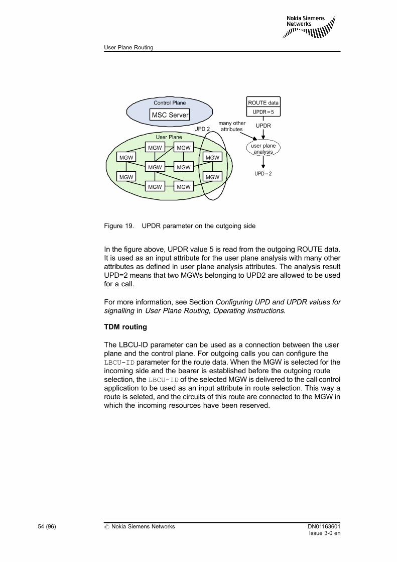
Figure 19. UPDR parameter on the outgoing side
In the figure above, UPDR value 5 is read from the outgoing ROUTE data.It is used as an input attribute for the user plane analysis with many otherattributes as defined in user plane analysis attributes. The analysis resultUPD=2 means that two MGWs belonging to UPD2 are allowed to be usedfor a call.
For more information, see Section Configuring UPD and UPDR values forsignalling in User Plane Routing, Operating instructions.
TDM routing
The LBCU-ID parameter can be used as a connection between the userplane and the control plane. For outgoing calls you can configure theLBCU-ID parameter for the route data. When the MGW is selected for theincoming side and the bearer is established before the outgoing routeselection, the LBCU-ID of the selected MGW is delivered to the call controlapplication to be used as an input attribute in route selection. This way aroute is seleted, and the circuits of this route are connected to the MGW inwhich the incoming resources have been reserved.
MSC Server
MGW
MGW
MGW
MGW
MGW
MGW
MGW
MGW
User Plane
MGW
MGW
Control Plane
UPD 2
ROUTE data
UPDR=5
UPDR
UPD=2
many otherattributes
user planeanalysis
54 (96) # Nokia Siemens Networks DN01163601Issue 3-0 en
User Plane Routing
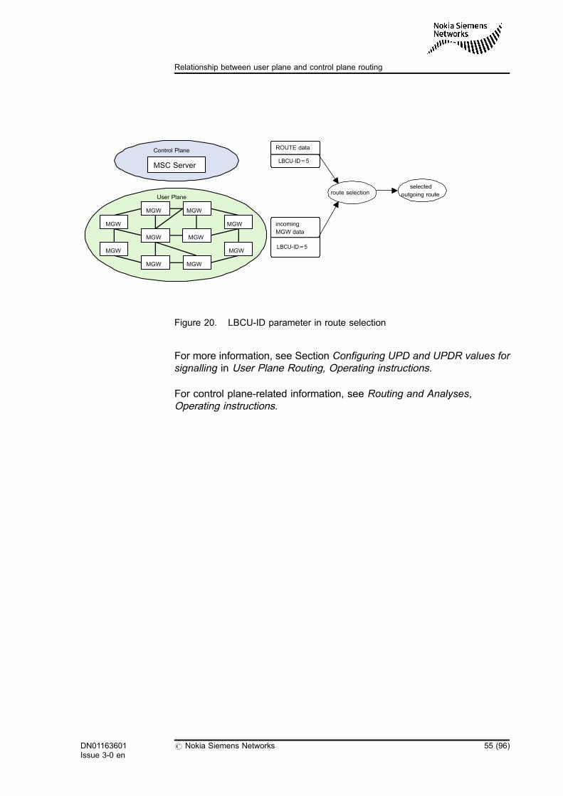
Figure 20. LBCU-ID parameter in route selection
For more information, see Section Configuring UPD and UPDR values forsignalling in User Plane Routing, Operating instructions.
For control plane-related information, see Routing and Analyses,Operating instructions.
MSC Server
MGW
MGW
MGW
MGW
MGW
MGW
MGW
MGW
User Plane
MGW
MGW
Control Plane ROUTE data
LBCU-ID=5
route selection
incoming
MGW data
LBCU-ID=5
selected
outgoing route
DN01163601Issue 3-0 en
# Nokia Siemens Networks 55 (96)
Relationship between user plane and control plane routing

56 (96) # Nokia Siemens Networks DN01163601Issue 3-0 en
User Plane Routing
7 MGW selection
MGW selection is a functionality in the MSC Server (MSS) which isnecessary for selecting an optimal MGW for user plane transmission for acall.
7.1 MGW selection basic functionality
In the case of physical TDM resources, the circuits are hunted on thecontrol plane level in the MSS. The circuit that has been assigned to thecall directly identifies the MGW where the resource is configured. In thiscase the MGW selection for the call is dictated by the TDM circuit. TheMGW where the circuit is configured is always selected.
In the case of ephemeral resources, like ATM AAL2 or IP, the situation isdifferent. There can be several MGW candidates that are suitable for userplane transmission for the call. The user plane-level MGW selectionprocedure is then invoked to find the available MGW candidates and tomake a selection among them.
Taking the MSS user plane routing application into consideration, theMGW selection procedure consists of the following logical subtasks:
1. Collecting control plane- and user plane -related information from thesignalling and call control applications.
2. Further processing of collected data in the user plane analysis. The'preceding UPD determination' and 'succeeding UPD determination'user plane analysis phases are executed in order to find UPDswhich contain the MGW candidates for a call.
In UE-originating or -terminating calls, the UPD is directly defined inthe radio network configuration data and it is provided for the userplane control application. In this case, the user plane analysisphases mentioned above are not executed for the UE side of thecall.
DN01163601Issue 3-0 en
# Nokia Siemens Networks 57 (96)
MGW selection
3. Collecting updates and possible changes to control plane- and userplane -related information from the signalling and call controlapplications. If the user plane control application receives newinformation, data processing is done again on condition that theactual resources of an MGW have not been reserved yet.
4. Selecting an MGW from the UPD. Selection can be done, forexample, by using load sharing weight values as specified in thefollowing sections.
The most optimal result of MGW selection is that the user plane is routedthrough an MGW under the scope of an MSS. This is the preferredfunctionality that the user plane control application targets during MGWselection. In such cases, the 'preceding UPD determination' and the'succeeding UPD determination' user plane analysis phases result in thesame UPD, and from that, the same MGW can be selected for theincoming and the outgoing side user plane. For more information, seeExample Selecting an MGW from the same UPDs.
Another optimal scenario is when the 'preceding UPD determination' andthe 'succeeding UPD determination' user plane analysis phases do notresult in the same UPD but the UPDs use the same MGW. In this case theuser plane routing application is able to optimise selection by finding andselecting the MGW shared by the UPDs for the call. For more information,see Examples Selecting an MGW from different UPDs sharing MGWs inUE-UE calls and and Selecting an MGW from different UPDs sharingMGWs in UE-CN calls.
Depending on the network configuration, it is possible to have two MGWsunder the scope of an MSS. This scenario is similar to the previous one,except that the UPDs do not always use the same MGW. When there is noshared MGW for the UPDs, an MGW is selected from the UPD belongingto the side which receives the resource reservation request first. Then the'Interconnecting BNC characteristics determination' user plane analysisphase is executed, and to find the possible MGW candidates for theremaining, incoming or outgoing, side, the user plane control applicationmakes a topology database inquiry to check the connectivity of MGWs inthe UPDs. MGWs without connectivity are ruled out from MGW selection.For more information, see Example Selecting an MGW from differentUPDs sharing no MGWs.
The MGW selection method might differ depending on the configuration(PRFILE setting). If the optimisation method is activated with theIC_CONF_OPT_IN_PHYS_MGW PRFILE parameter, an MGW is selectedfrom the UPD belonging to the side which receives the resourcereservation request first, and a list of the possible MGW candidates iscreated. The list contains the virtual MGWs in the opposite UPD whichbelong to the same physical MGW as the already selected virtual MGW. If
58 (96) # Nokia Siemens Networks DN01163601Issue 3-0 en
User Plane Routing
there is such a virtual MGW in the opposite UPD, neither the'interconnecting BNC characteristics determination' user plane analysis isexecuted nor the topology database is inquired, but the 'interconnectingBNC characteristics' is set to AAL2 automatically. For more information,see Example Selecting an MGW from different UPDs with the samephysical MGW.
If it is not possible to find a virtual MGW in the opposite UPD whichbelongs to the same physical MGW, the 'interconnecting BNCcharacteristics determination' analysis is executed and the topologydatabase is inquired as described above.
TDM usage optimisation
The IC_CONF_OPT_IN_PHYS_MGW PRFILE parameter is also used toactivate the TDM usage optimisation functionality. In the case of a TDM-terminating call – when the incoming side MGW is already selected andthe outgoing side MGW, where the TDM circuit is connected, belongs to adifferent virtual MGW, but to the same physical MGW – the MSS reservesthe outgoing side TDM termination in the incoming side MGW. With theTDM usage optimisation functionality, it is not necessary to make aconnection between these virtual MGWs.
The same functionality applies to both PSTN and MS-terminating callcases.
Note
TDM circuit pools are defined for virtual MGWs. TDM circuits arereserved through the H.248 interface, which is used for controlling thevirtual MGW.
To avoid backbone connections between virtual MGWs within aphysical MGW, the Nokia MSC server controlling the Nokia MGW canalso reserve TDM circuits belonging to another virtual MGW in thesame physical MGW.
DN01163601Issue 3-0 en
# Nokia Siemens Networks 59 (96)
MGW selection
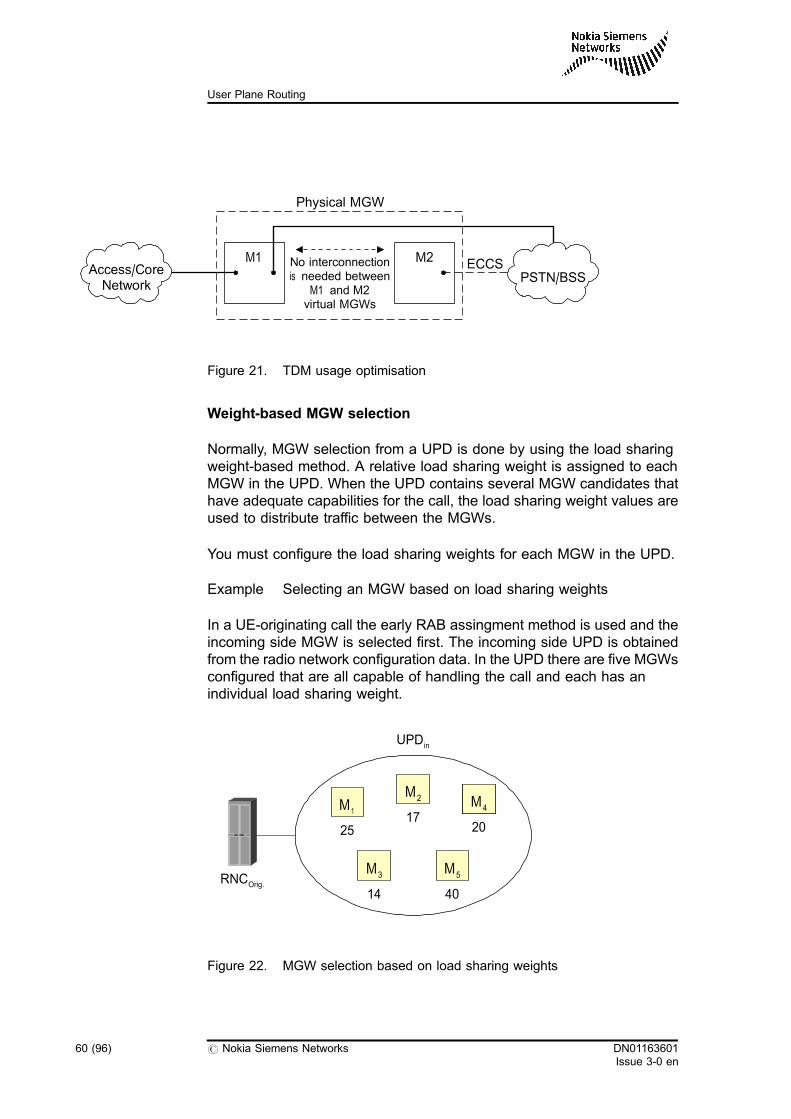
Figure 21. TDM usage optimisation
Weight-based MGW selection
Normally, MGW selection from a UPD is done by using the load sharingweight-based method. A relative load sharing weight is assigned to eachMGW in the UPD. When the UPD contains several MGW candidates thathave adequate capabilities for the call, the load sharing weight values areused to distribute traffic between the MGWs.
You must configure the load sharing weights for each MGW in the UPD.
Example Selecting an MGW based on load sharing weights
In a UE-originating call the early RAB assingment method is used and theincoming side MGW is selected first. The incoming side UPD is obtainedfrom the radio network configuration data. In the UPD there are five MGWsconfigured that are all capable of handling the call and each has anindividual load sharing weight.
Figure 22. MGW selection based on load sharing weights
Physical MGW
ECCSNo interconnectionis needed between
M1 and M2virtual MGWs
M1 M2
PSTN/BSSAccess/CoreNetwork
M1
25
M2
17M5M4
20
M3
14
M5
40
UPDin
RNCOrig.
60 (96) # Nokia Siemens Networks DN01163601Issue 3-0 en
User Plane Routing
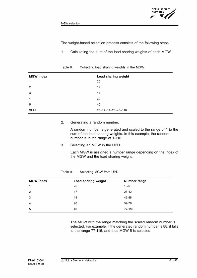
The weight-based selection process consists of the following steps:
1. Calculating the sum of the load sharing weights of each MGW.
Table 8. Collecting load sharing weights in the MGW
MGW index Load sharing weight
1 25
2 17
3 14
4 20
5 40
SUM 25+17+14+20+40=116
2. Generating a random number.
A random number is generated and scaled to the range of 1 to thesum of the load sharing weights. In this example, the randomnumber is in the range of 1-116.
3. Selecting an MGW in the UPD.
Each MGW is assigned a number range depending on the index ofthe MGW and the load sharing weight.
Table 9. Selecting MGW from UPD
MGW index Load sharing weight Number range
1 25 1-25
2 17 26-42
3 14 43-56
4 20 57-76
5 40 77-116
The MGW with the range matching the scaled random number isselected. For example, if the generated random number is 88, it fallsto the range 77-116, and thus MGW 5 is selected.
DN01163601Issue 3-0 en
# Nokia Siemens Networks 61 (96)
MGW selection
The load sharing weight-based MGW selection method provides a flexiblemechanism for weighted traffic distribution between MGWs. When newMGWs are added to a UPD or MGWs are removed from a UPD, the trafficis automatically distributed among all the MGWs depending on theirrelative weight. Note that the relative load sharing weights of the otherMGWs in a UPD remain unchanged when a new MGW is added to a UPDor an MGW is removed from a UPD. This means that adding or removingan MGW also has an effect on the amount of traffic that is routed throughthe other MGWs. The traffic from the other MGWs is either directed to thenew MGW or it is directed from the removed MGW to other MGWs.
If an MGW has a load sharing weight defined as zero in a certain UPD, notraffic that is directed to that UPD is routed through that MGW.
The same MGW can belong to several different UPDs and can have adifferent load sharing weight in each UPD. The total traffic directed to anMGW is the sum of the substreams of traffic that is directed to the MGWfrom each UPD.
MGW selection in different call cases
In the previous example simple weight-based selection from one UPD wasdescribed. This kind of logic is used, for example, in UE-originating callstowards another MSS with early RAB assignment, when only thepreceding UPD is known at the time of the MGW selection. Normally,during the call setup, there are situations when both UPDs are known andMGW selection is made. In these cases an attempt to optimise theselection is made by trying to select an MGW that belongs to both UPDs.The task is to route the call only through one MGW. When optimisation isnot possible, MGWs with suitable interconnection are selected. Thedifferent scenarios are discussed in the following examples.
Example Selecting an MGW from the same UPDs
In an intra-MSS UE-UE call both the preceding and the succeeding UPDsare known when MGW selection is made. The early RAB assignmentmethod is always used in intra-MSS call cases and the incoming sideMGW is always selected first. Both the preceding and the succeedingUPDs are obtained from the radio network configuration data. In thisexample, the incoming and the outgoing UPDs are the same.
62 (96) # Nokia Siemens Networks DN01163601Issue 3-0 en
User Plane Routing
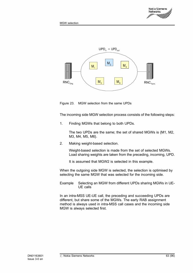
Figure 23. MGW selection from the same UPDs
The incoming side MGW selection process consists of the following steps:
1. Finding MGWs that belong to both UPDs.
The two UPDs are the same; the set of shared MGWs is {M1, M2,M3, M4, M5, M6}.
2. Making weight-based selection.
Weight-based selection is made from the set of selected MGWs.Load sharing weights are taken from the preceding, incoming, UPD.
It is assumed that MGW2 is selected in this example.
When the outgoing side MGW is selected, the selection is optimised byselecting the same MGW that was selected for the incoming side.
Example Selecting an MGW from different UPDs sharing MGWs in UE-UE calls
In an intra-MSS UE-UE call, the preceding and succeeding UPDs aredifferent, but share some of the MGWs. The early RAB assignmentmethod is always used in intra-MSS call cases and the incoming sideMGW is always selected first.
M1
M2 M5M4
M3 M6
UPDin = UPDout
RNCOrig. RNCTerm.
DN01163601Issue 3-0 en
# Nokia Siemens Networks 63 (96)
MGW selection
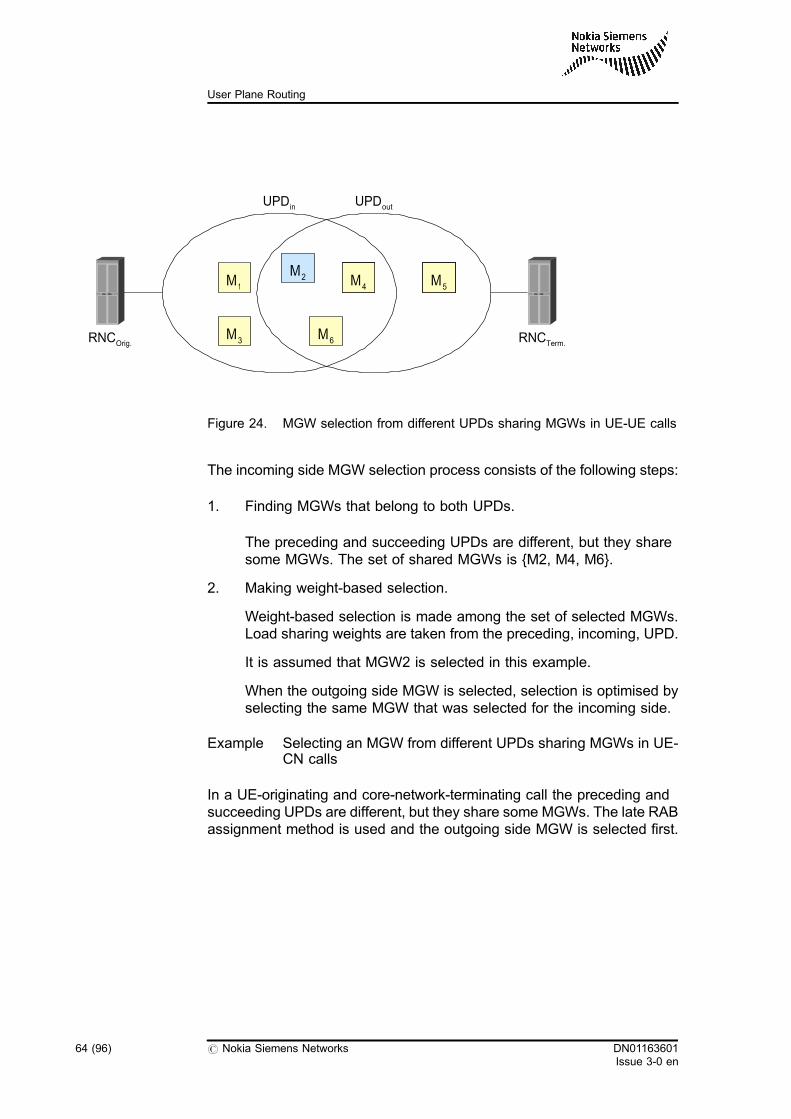
Figure 24. MGW selection from different UPDs sharing MGWs in UE-UE calls
The incoming side MGW selection process consists of the following steps:
1. Finding MGWs that belong to both UPDs.
The preceding and succeeding UPDs are different, but they sharesome MGWs. The set of shared MGWs is {M2, M4, M6}.
2. Making weight-based selection.
Weight-based selection is made among the set of selected MGWs.Load sharing weights are taken from the preceding, incoming, UPD.
It is assumed that MGW2 is selected in this example.
When the outgoing side MGW is selected, selection is optimised byselecting the same MGW that was selected for the incoming side.
Example Selecting an MGW from different UPDs sharing MGWs in UE-CN calls
In a UE-originating and core-network-terminating call the preceding andsucceeding UPDs are different, but they share some MGWs. The late RABassignment method is used and the outgoing side MGW is selected first.
M5M5
RNCTerm.
UPDin
RNCOrig.
M1
M2 M5M4
M3 M6
UPDout
64 (96) # Nokia Siemens Networks DN01163601Issue 3-0 en
User Plane Routing
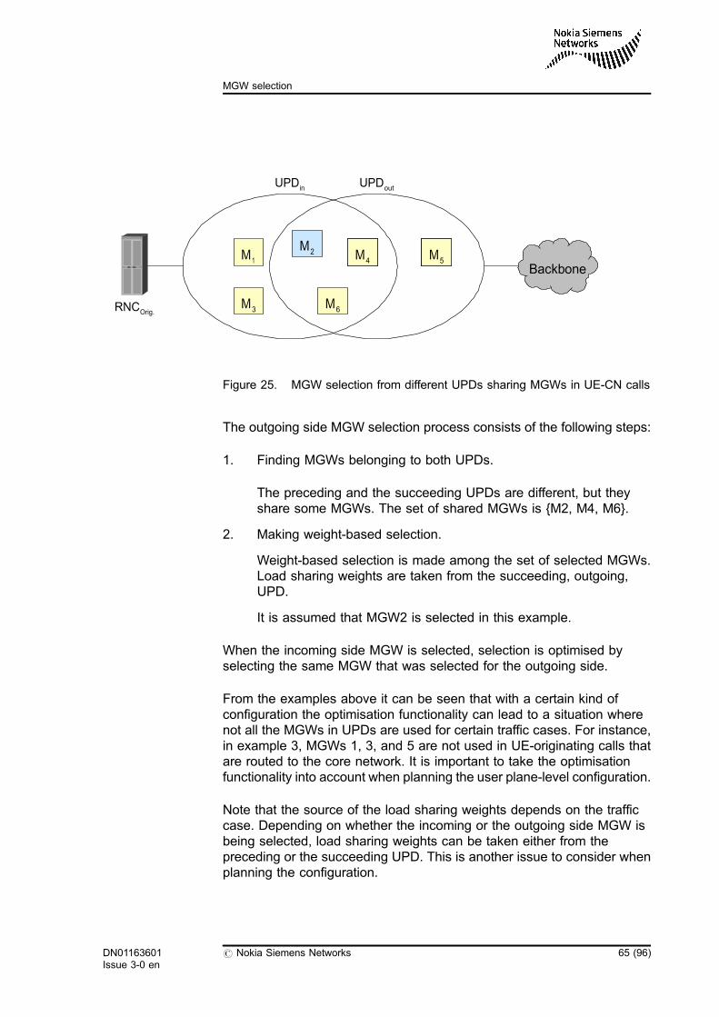
Figure 25. MGW selection from different UPDs sharing MGWs in UE-CN calls
The outgoing side MGW selection process consists of the following steps:
1. Finding MGWs belonging to both UPDs.
The preceding and the succeeding UPDs are different, but theyshare some MGWs. The set of shared MGWs is {M2, M4, M6}.
2. Making weight-based selection.
Weight-based selection is made among the set of selected MGWs.Load sharing weights are taken from the succeeding, outgoing,UPD.
It is assumed that MGW2 is selected in this example.
When the incoming side MGW is selected, selection is optimised byselecting the same MGW that was selected for the outgoing side.
From the examples above it can be seen that with a certain kind ofconfiguration the optimisation functionality can lead to a situation wherenot all the MGWs in UPDs are used for certain traffic cases. For instance,in example 3, MGWs 1, 3, and 5 are not used in UE-originating calls thatare routed to the core network. It is important to take the optimisationfunctionality into account when planning the user plane-level configuration.
Note that the source of the load sharing weights depends on the trafficcase. Depending on whether the incoming or the outgoing side MGW isbeing selected, load sharing weights can be taken either from thepreceding or the succeeding UPD. This is another issue to consider whenplanning the configuration.
M5M5
UPDin
RNCOrig.
M1
M2 M5M4
M3 M6
UPDout
Backbone
DN01163601Issue 3-0 en
# Nokia Siemens Networks 65 (96)
MGW selection
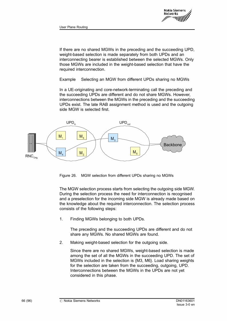
If there are no shared MGWs in the preceding and the succeeding UPD,weight-based selection is made separately from both UPDs and aninterconnecting bearer is established between the selected MGWs. Onlythose MGWs are included in the weight-based selection that have therequired interconnection.
Example Selecting an MGW from different UPDs sharing no MGWs
In a UE-originating and core-network-terminating call the preceding andthe succeeding UPDs are different and do not share MGWs. However,interconnections between the MGWs in the preceding and the succeedingUPDs exist. The late RAB assignment method is used and the outgoingside MGW is selected first.
Figure 26. MGW selection from different UPDs sharing no MGWs
The MGW selection process starts from selecting the outgoing side MGW.During the selection process the need for interconnection is recognisedand a preselection for the incoming side MGW is already made based onthe knowledge about the required interconnection. The selection processconsists of the following steps:
1. Finding MGWs belonging to both UPDs.
The preceding and the succeeding UPDs are different and do notshare any MGWs. No shared MGWs are found.
2. Making weight-based selection for the outgoing side.
Since there are no shared MGWs, weight-based selection is madeamong the set of all the MGWs in the succeeding UPD. The set ofMGWs included in the selection is {M3, M6}. Load sharing weightsfor the selection are taken from the succeeding, outgoing, UPD.Interconnections between the MGWs in the UPDs are not yetconsidered in this phase.
UPDin UPDout
RNCOrig.
M5M5M1
M2
Backbone
M6M4
M5M3
66 (96) # Nokia Siemens Networks DN01163601Issue 3-0 en
User Plane Routing
It is assumed that MGW3 is selected in this example.
3. Finding interconnection characteristics.
The need for interconnection between the MGWs in the precedingand succeeding UPD is recognised. The 'interconnecting BNCcharacteristics determination' user plane analysis phase is executedto find out the required BNC characteristics for the interconnection.
4. Finding interconnected MGWs.
The set of MGWs with the required type of interconnection iscomposed using the information stored in the topology database.The MGWs without the required type of interconnection areexcluded from the set assuming that all the MGWs in the precedingUPD have the right type of interconnection. The set of theinterconnected MGWs is {M1, M2, M4, M5}.
5. Making weight-based selection for the incoming side.
Weight-based selection is made among the set of interconnectedMGWs in the preceding UPD. Load sharing weights are taken fromthe preceding, incoming, UPD.
It is assumed that MGW4 is selected in this example.
Note
In this example, the whole MGW selection process takes place whenthe outgoing side resource reservation and MGW selection are needed.Although also the incoming side MGW is selected, this selection is onlya preselection without actual resource reservation from the incomingside MGW. Resource reservation is made later when the incoming sidebearer establishment is started. The purpose of the preselection is tocheck if a sufficient incoming side MGW with the requiredinterconnection is available for the call. If some changes regarding theincoming side resources take place during the call setup, before theincoming side resource reservation is made, the incoming side MGWselection can be repeated taking the changed information into account.For example, if the preceding UPD is changed because of the signallingphase handover, MGW selection is repeated for MGWs belonging tothe new UPD when an incoming side resource reservation is needed.
If the result of the user plane analysis in Step Finding interconnectioncharacteristics is loadshare, the next step is to make a weight-basedMGW selection for the incoming side, and after that to make a weight-based bearer selection for the interconnecting bearer types configuredbetween the selected MGWs.
DN01163601Issue 3-0 en
# Nokia Siemens Networks 67 (96)
MGW selection
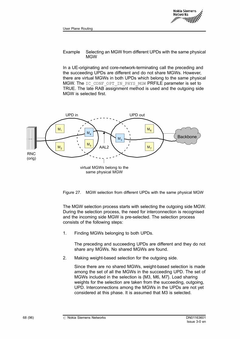
Example Selecting an MGW from different UPDs with the same physicalMGW
In a UE-originating and core-network-terminating call the preceding andthe succeeding UPDs are different and do not share MGWs. However,there are virtual MGWs in both UPDs which belong to the same physicalMGW. The IC_CONF_OPT_IN_PHYS_MGW PRFILE parameter is set toTRUE. The late RAB assignment method is used and the outgoing sideMGW is selected first.
Figure 27. MGW selection from different UPDs with the same physical MGW
The MGW selection process starts with selecting the outgoing side MGW.During the selection process, the need for interconnection is recognisedand the incoming side MGW is pre-selected. The selection processconsists of the following steps:
1. Finding MGWs belonging to both UPDs.
The preceding and succeeding UPDs are different and they do notshare any MGWs. No shared MGWs are found.
2. Making weight-based selection for the outgoing side.
Since there are no shared MGWs, weight-based selection is madeamong the set of all the MGWs in the succeeding UPD. The set ofMGWs included in the selection is {M3, M6, M7}. Load sharingweights for the selection are taken from the succeeding, outgoing,UPD. Interconnections among the MGWs in the UPDs are not yetconsidered at this phase. It is assumed that M3 is selected.
RNC(orig)
M1
M2
M4
M5
M3
M6
M7
UPD in UPD out
virtual MGWs belong to thesame physical MGW
AAL2
Backbone
68 (96) # Nokia Siemens Networks DN01163601Issue 3-0 en
User Plane Routing
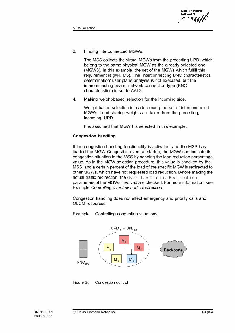
3. Finding interconnected MGWs.
The MSS collects the virtual MGWs from the preceding UPD, whichbelong to the same physical MGW as the already selected one(MGW3). In this example, the set of the MGWs which fulfill thisrequirement is {M4, M5}. The 'interconnecting BNC characteristicsdetermination' user plane analysis is not executed, but theinterconnecting bearer network connection type (BNCcharacteristics) is set to AAL2.
4. Making weight-based selection for the incoming side.
Weight-based selection is made among the set of interconnectedMGWs. Load sharing weights are taken from the preceding,incoming, UPD.
It is assumed that MGW4 is selected in this example.
Congestion handling
If the congestion handling functionality is activated, and the MSS hasloaded the MGW Congestion event at startup, the MGW can indicate itscongestion situation to the MSS by sending the load reduction percentagevalue. As in the MGW selection procedure, this value is checked by theMSS, and a certain percent of the load of the specific MGW is redirected toother MGWs, which have not requested load reduction. Before making theactual traffic redirection, the Overflow Traffic Redirectionparameters of the MGWs involved are checked. For more information, seeExample Controlling overflow traffic redirection.
Congestion handling does not affect emergency and priority calls andOLCM resources.
Example Controlling congestion situations
Figure 28. Congestion control
UPDin = UPDout
RNCOrig.
M1
M2
M6
M4
M5M3
Backbone
DN01163601Issue 3-0 en
# Nokia Siemens Networks 69 (96)
MGW selection
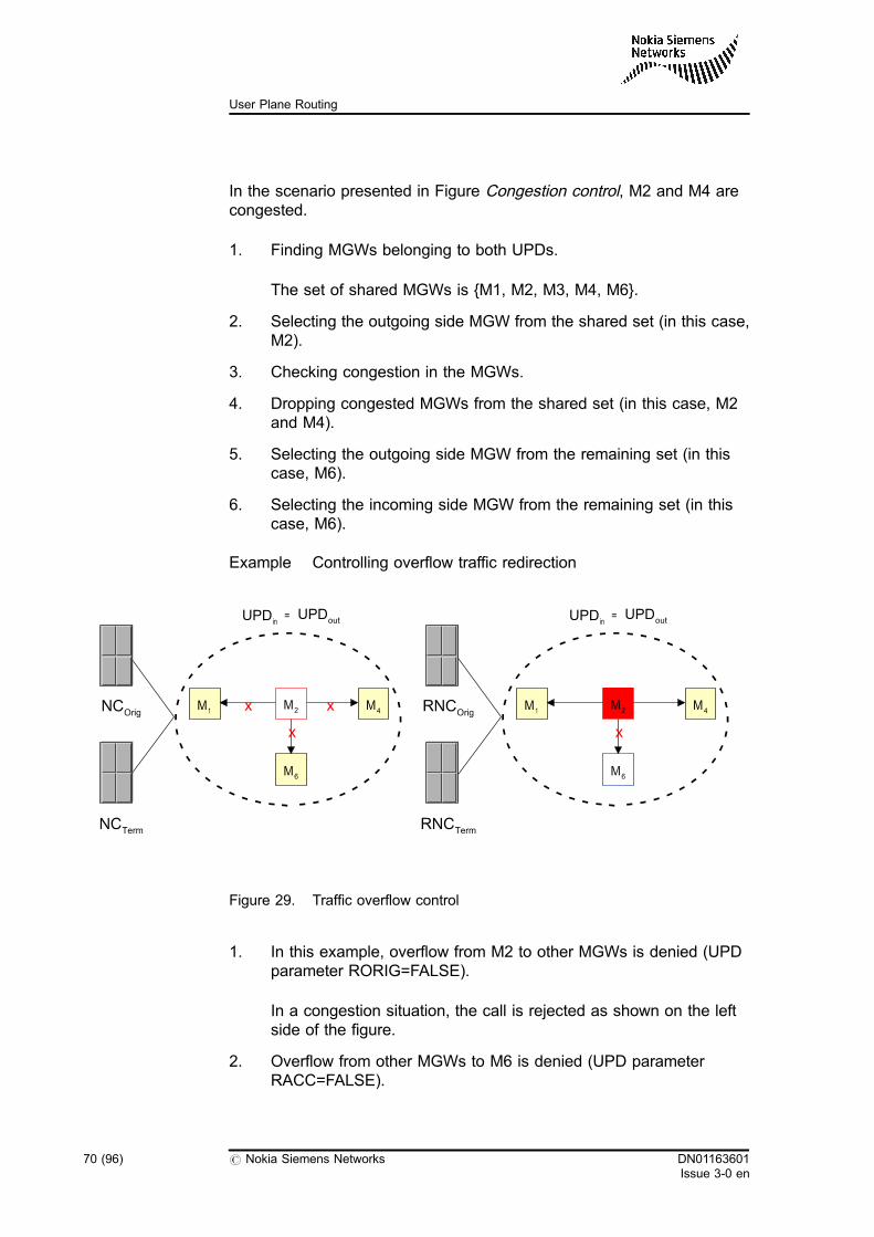
In the scenario presented in Figure Congestion control, M2 and M4 arecongested.
1. Finding MGWs belonging to both UPDs.
The set of shared MGWs is {M1, M2, M3, M4, M6}.
2. Selecting the outgoing side MGW from the shared set (in this case,M2).
3. Checking congestion in the MGWs.
4. Dropping congested MGWs from the shared set (in this case, M2and M4).
5. Selecting the outgoing side MGW from the remaining set (in thiscase, M6).
6. Selecting the incoming side MGW from the remaining set (in thiscase, M6).
Example Controlling overflow traffic redirection
Figure 29. Traffic overflow control
1. In this example, overflow from M2 to other MGWs is denied (UPDparameter RORIG=FALSE).
In a congestion situation, the call is rejected as shown on the leftside of the figure.
2. Overflow from other MGWs to M6 is denied (UPD parameterRACC=FALSE).
NCOrigM1
M2
M6
M4
UPDin = UPDout
NCTerm
x x
x
RNCOrigM1
M2
M6
M4
UPDin = UPDout
RNCTerm
x
70 (96) # Nokia Siemens Networks DN01163601Issue 3-0 en
User Plane Routing
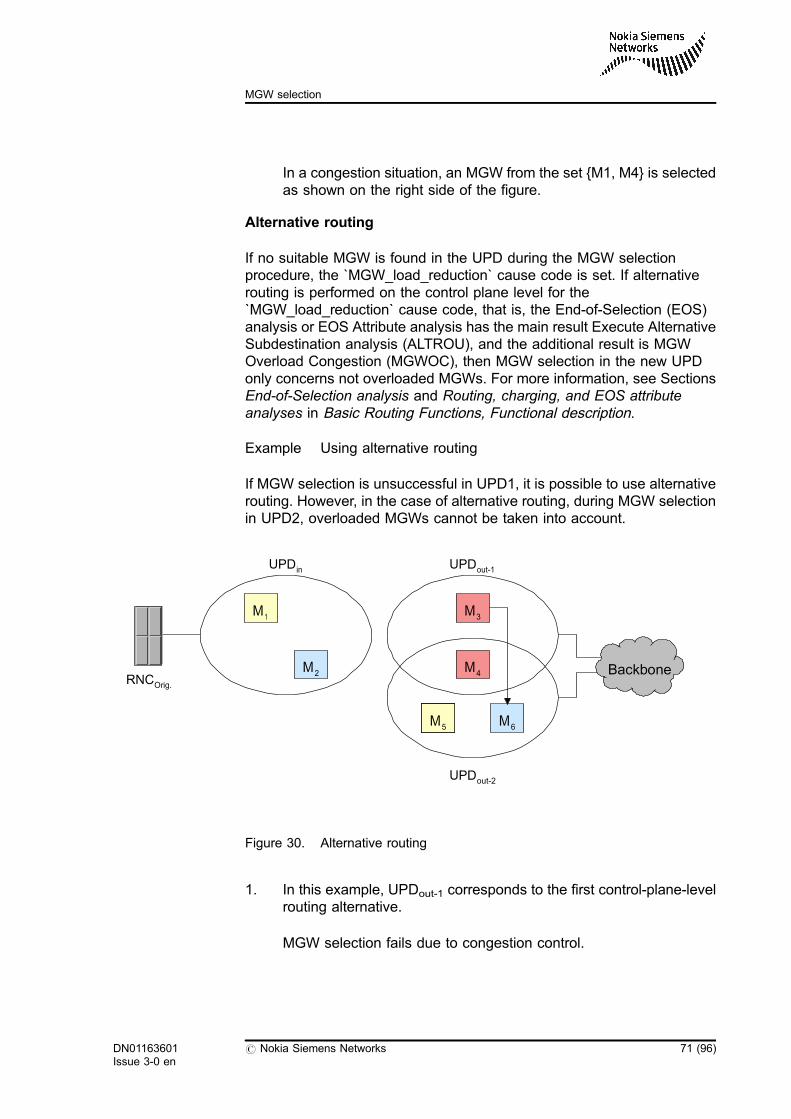
In a congestion situation, an MGW from the set {M1, M4} is selectedas shown on the right side of the figure.
Alternative routing
If no suitable MGW is found in the UPD during the MGW selectionprocedure, the `MGW_load_reduction` cause code is set. If alternativerouting is performed on the control plane level for the`MGW_load_reduction` cause code, that is, the End-of-Selection (EOS)analysis or EOS Attribute analysis has the main result Execute AlternativeSubdestination analysis (ALTROU), and the additional result is MGWOverload Congestion (MGWOC), then MGW selection in the new UPDonly concerns not overloaded MGWs. For more information, see SectionsEnd-of-Selection analysis and Routing, charging, and EOS attributeanalyses in Basic Routing Functions, Functional description.
Example Using alternative routing
If MGW selection is unsuccessful in UPD1, it is possible to use alternativerouting. However, in the case of alternative routing, during MGW selectionin UPD2, overloaded MGWs cannot be taken into account.
Figure 30. Alternative routing
1. In this example, UPDout-1 corresponds to the first control-plane-levelrouting alternative.
MGW selection fails due to congestion control.
UPDin UPDout-1
RNCOrig.
M1
M2
M5M5 M6
M4
M5M3
UPDout-2
Backbone
DN01163601Issue 3-0 en
# Nokia Siemens Networks 71 (96)
MGW selection
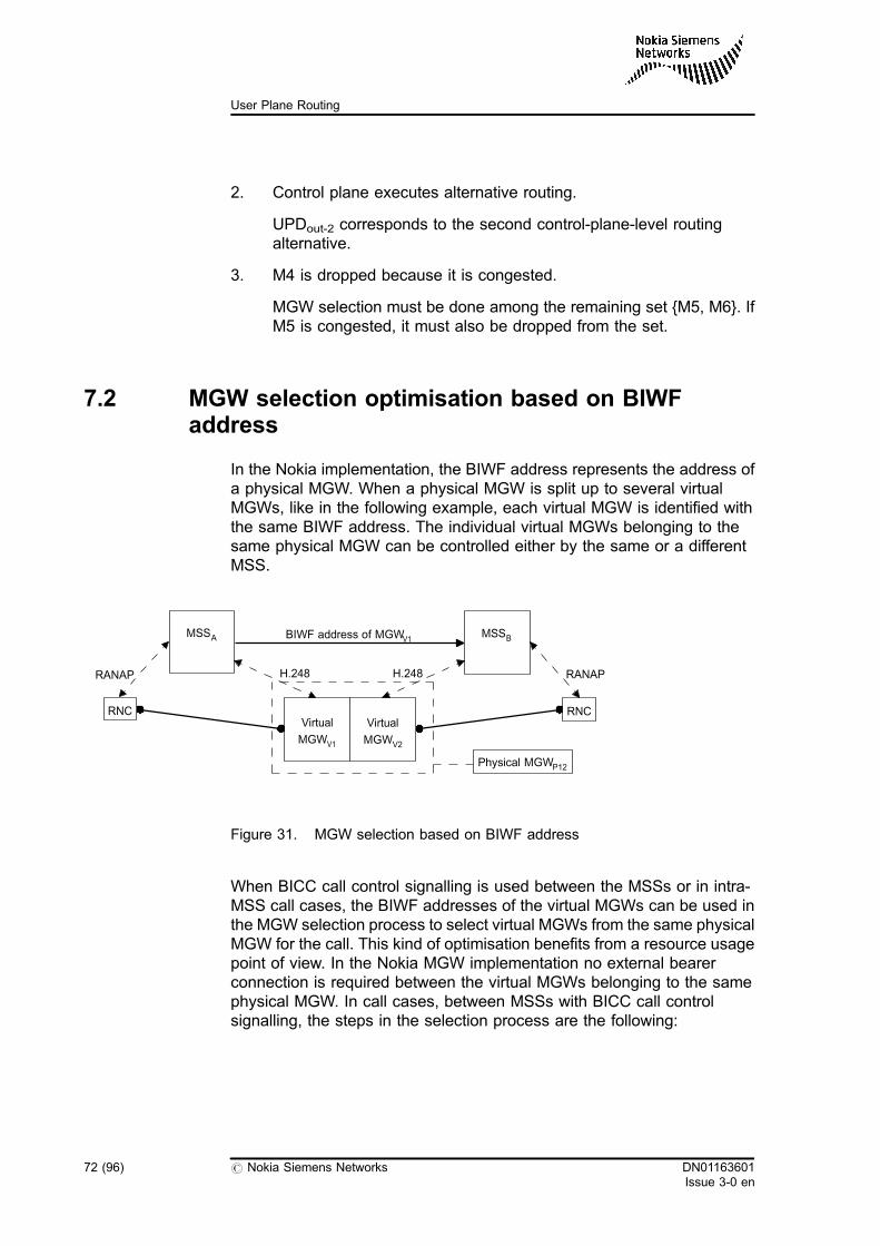
2. Control plane executes alternative routing.
UPDout-2 corresponds to the second control-plane-level routingalternative.
3. M4 is dropped because it is congested.
MGW selection must be done among the remaining set {M5, M6}. IfM5 is congested, it must also be dropped from the set.
7.2 MGW selection optimisation based on BIWFaddress
In the Nokia implementation, the BIWF address represents the address ofa physical MGW. When a physical MGW is split up to several virtualMGWs, like in the following example, each virtual MGW is identified withthe same BIWF address. The individual virtual MGWs belonging to thesame physical MGW can be controlled either by the same or a differentMSS.
Figure 31. MGW selection based on BIWF address
When BICC call control signalling is used between the MSSs or in intra-MSS call cases, the BIWF addresses of the virtual MGWs can be used inthe MGW selection process to select virtual MGWs from the same physicalMGW for the call. This kind of optimisation benefits from a resource usagepoint of view. In the Nokia MGW implementation no external bearerconnection is required between the virtual MGWs belonging to the samephysical MGW. In call cases, between MSSs with BICC call controlsignalling, the steps in the selection process are the following:
MSSA BIWF address of MGWV1
RANAPRANAP H.248H.248
Physical MGWP12
Virtual
MGWV1
Virtual
MGWV2
MSSB
RNCRNC
72 (96) # Nokia Siemens Networks DN01163601Issue 3-0 en
User Plane Routing
1. The BIWF address is received from the preceding node in the IAM orfrom the succeeding node in the APM, depending on the used BICCbearer establishment method.
In the case of backward establishment or forward establishment withnon-delayed MGW selection, MSS A first selects an MGW for thecall. In this case MSS B receives the BIWF address of the selectedMGW in the IAM.
In the case of forward establishment with delayed MGW selection,MSS B first selects an MGW for the call. In this case, MSS Areceives the BIWF address of the selected MGW in the APM.
2. The received BIWF address is analysed by the MSS during theMGW selection procedure. The MSS recognises that a virtual MGWwith the same BIWF address is included in the previouslydetermined UPD towards the other node. Since the BIWF addressesof the MGWs are the same, this means that the used virtual MGWsare physically located in the same network element.
3. The MSS selects the virtual MGW from the same physical MGW forthe call.
Note
If there are several virtual MGWs in the UPD which belong to the samephysical MGW, the MSS selects one of the MGWs that are based onthe defined load sharing value. For more information, see Section 7.1MGW selection basic functionality.
7.3 MGW selection optimisation based on BCU-ID
When BICC call control signalling is used, the MGW selection can also beoptimised using the BCU-ID that is received from the peer MSS. The BCU-ID is a logical identifier of the MGW that has been selected for user planetraffic by the peer MSS. In the Nokia implementation, it can be configuredto be unique on a virtual MGW basis.
The BCU-ID can affect MGW selection through the user plane analysis,where it is available as an attribute. Depending on the call case and theused BICC bearer establishment method, it can be used to optimise thepreceding or succeeding UPD selection. This way it can be used to selectan optimal set of MGWs, identified by the UPD, among which the MGW forthe user plane traffic is selected.
DN01163601Issue 3-0 en
# Nokia Siemens Networks 73 (96)
MGW selection
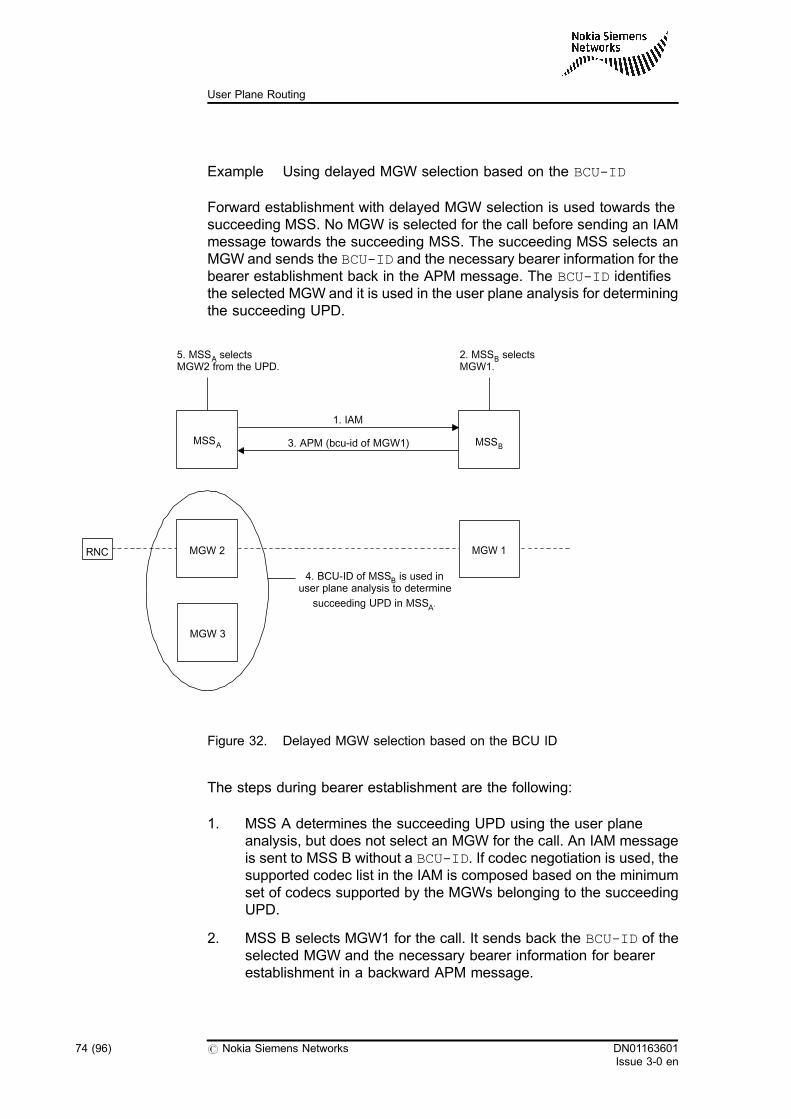
Example Using delayed MGW selection based on the BCU-ID
Forward establishment with delayed MGW selection is used towards thesucceeding MSS. No MGW is selected for the call before sending an IAMmessage towards the succeeding MSS. The succeeding MSS selects anMGW and sends the BCU-ID and the necessary bearer information for thebearer establishment back in the APM message. The BCU-ID identifiesthe selected MGW and it is used in the user plane analysis for determiningthe succeeding UPD.
Figure 32. Delayed MGW selection based on the BCU ID
The steps during bearer establishment are the following:
1. MSS A determines the succeeding UPD using the user planeanalysis, but does not select an MGW for the call. An IAM messageis sent to MSS B without a BCU-ID. If codec negotiation is used, thesupported codec list in the IAM is composed based on the minimumset of codecs supported by the MGWs belonging to the succeedingUPD.
2. MSS B selects MGW1 for the call. It sends back the BCU-ID of theselected MGW and the necessary bearer information for bearerestablishment in a backward APM message.
MSSBMSSA
MGW 2
MGW 3
RNC MGW 1
5. MSSA selectsMGW2 from the UPD.
2. MSSB selectsMGW1.
1. IAM
3. APM (bcu-id of MGW1)
4. BCU-ID of MSSB is used inuser plane analysis to determine
succeeding UPD in MSSA.
74 (96) # Nokia Siemens Networks DN01163601Issue 3-0 en
User Plane Routing
3. MSS A re-determines the succeeding UPD by re-executing the userplane analysis. Re-execution of the user plane analysis can resulteither in the same succeeding UPD as the one determined in the firststep or in a different one.
4. MSS A selects an MGW from the succeeding UPD. Note that MGWselection inside the UPD can be further optimised using the BIWFaddress. For more information, see Section 7.2 MGW selectionoptimisation based on BIWF address.
Note
If the succeeding UPD is changed, codec negotiation is used, and noMGW supporting the selected codec is available in the new UPD, thecall is released.
Similar optimisation is possible when other bearer establishment methodsare used. In the case of backward establishment or forward establishmentwith non-delayed MGW selection, the preceding UPD selection in thesucceeding MSS can be optimised by using the BCU-ID in the user planeanalysis.
7.4 Tandem operation in MGW selection
When a special resource is not available in the MGW where the user planeconnection has been created, a tandem operation is used to direct theuser plane to an appropriate MGW.
In the following case a special resource is needed and that is aninterconnection PCM line to MSS A. There is no such connection betweenMSS A and MGW1, and therefore, a tandem operation is needed to find anMGW tandem which is able to provide the special resource in question.
DN01163601Issue 3-0 en
# Nokia Siemens Networks 75 (96)
MGW selection
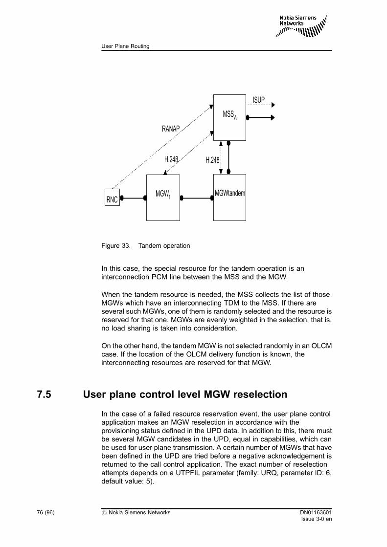
Figure 33. Tandem operation
In this case, the special resource for the tandem operation is aninterconnection PCM line between the MSS and the MGW.
When the tandem resource is needed, the MSS collects the list of thoseMGWs which have an interconnecting TDM to the MSS. If there areseveral such MGWs, one of them is randomly selected and the resource isreserved for that one. MGWs are evenly weighted in the selection, that is,no load sharing is taken into consideration.
On the other hand, the tandem MGW is not selected randomly in an OLCMcase. If the location of the OLCM delivery function is known, theinterconnecting resources are reserved for that MGW.
7.5 User plane control level MGW reselection
In the case of a failed resource reservation event, the user plane controlapplication makes an MGW reselection in accordance with theprovisioning status defined in the UPD data. In addition to this, there mustbe several MGW candidates in the UPD, equal in capabilities, which canbe used for user plane transmission. A certain number of MGWs that havebeen defined in the UPD are tried before a negative acknowledgement isreturned to the call control application. The exact number of reselectionattempts depends on a UTPFIL parameter (family: URQ, parameter ID: 6,default value: 5).
RANAP
H.248H.248
ISUP
MSSA
MGWtandemMGW1RNC
76 (96) # Nokia Siemens Networks DN01163601Issue 3-0 en
User Plane Routing
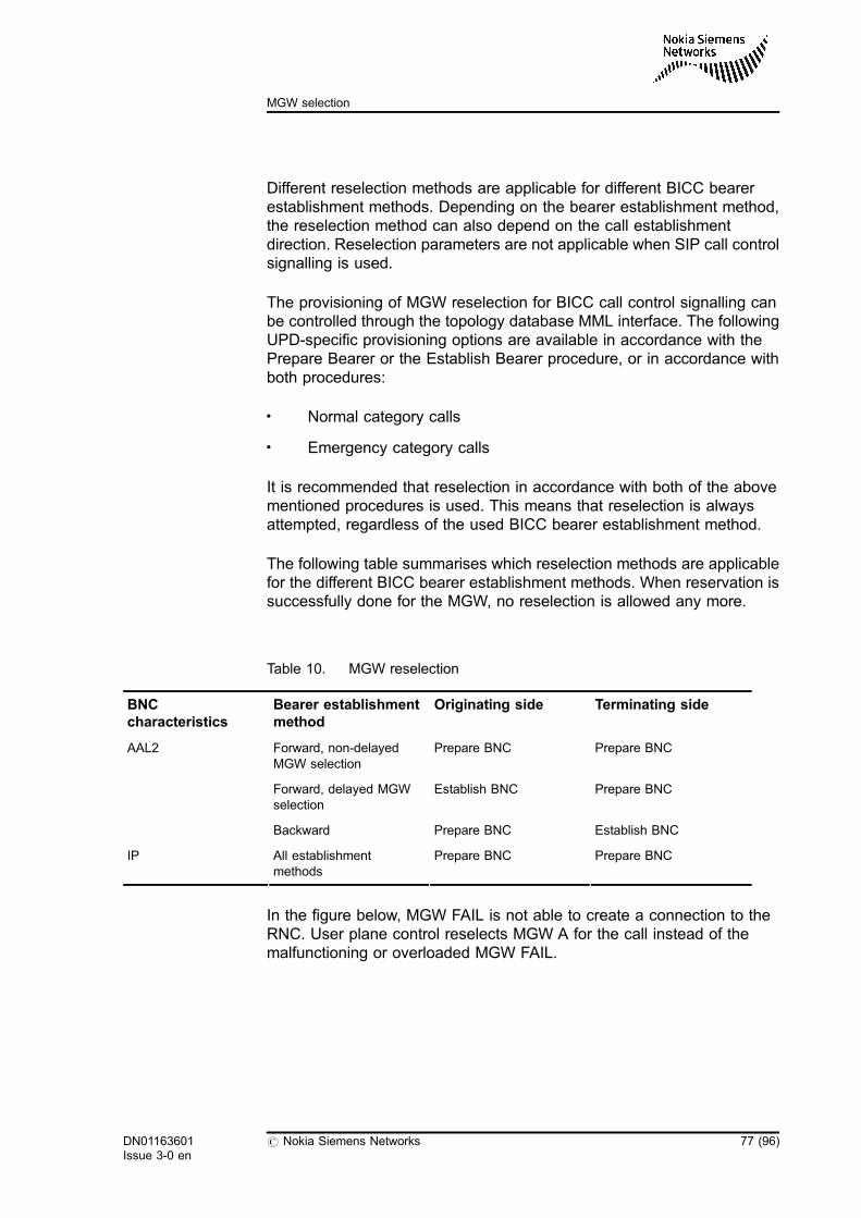
Different reselection methods are applicable for different BICC bearerestablishment methods. Depending on the bearer establishment method,the reselection method can also depend on the call establishmentdirection. Reselection parameters are not applicable when SIP call controlsignalling is used.
The provisioning of MGW reselection for BICC call control signalling canbe controlled through the topology database MML interface. The followingUPD-specific provisioning options are available in accordance with thePrepare Bearer or the Establish Bearer procedure, or in accordance withboth procedures:
. Normal category calls
. Emergency category calls
It is recommended that reselection in accordance with both of the abovementioned procedures is used. This means that reselection is alwaysattempted, regardless of the used BICC bearer establishment method.
The following table summarises which reselection methods are applicablefor the different BICC bearer establishment methods. When reservation issuccessfully done for the MGW, no reselection is allowed any more.
Table 10. MGW reselection
BNCcharacteristics
Bearer establishmentmethod
Originating side Terminating side
AAL2 Forward, non-delayedMGW selection
Prepare BNC Prepare BNC
Forward, delayed MGWselection
Establish BNC Prepare BNC
Backward Prepare BNC Establish BNC
IP All establishmentmethods
Prepare BNC Prepare BNC
In the figure below, MGW FAIL is not able to create a connection to theRNC. User plane control reselects MGW A for the call instead of themalfunctioning or overloaded MGW FAIL.
DN01163601Issue 3-0 en
# Nokia Siemens Networks 77 (96)
MGW selection
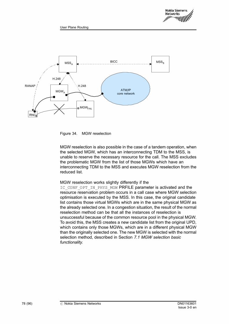
Figure 34. MGW reselection
MGW reselection is also possible in the case of a tandem operation, whenthe selected MGW, which has an interconnecting TDM to the MSS, isunable to reserve the necessary resource for the call. The MSS excludesthe problematic MGW from the list of those MGWs which have aninterconnecting TDM to the MSS and executes MGW reselection from thereduced list.
MGW reselection works slightly differently if theIC_CONF_OPT_IN_PHYS_MGW PRFILE parameter is activated and theresource reservation problem occurs in a call case where MGW selectionoptimisation is executed by the MSS. In this case, the original candidatelist contains those virtual MGWs which are in the same physical MGW asthe already selected one. In a congestion situation, the result of the normalreselection method can be that all the instances of reselection isunsuccessful because of the common resource pool in the physical MGW.To avoid this, the MSS creates a new candidate list from the original UPD,which contains only those MGWs, which are in a different physical MGWthan the originally selected one. The new MGW is selected with the normalselection method, described in Section 7.1 MGW selection basicfunctionality.
MSSB
MGWA
MSSA
MGWFAIL
RNC
RANAP
H.248
H.248
BICC
ATM/IPcore network
78 (96) # Nokia Siemens Networks DN01163601Issue 3-0 en
User Plane Routing
7.6 MGW selection in TDM routing
When TDM is used as an outgoing resource and the incoming resourcesare already reserved before route selection, MGW selection can also beoptimised using the BCU-ID of the already reserved MGW. In the Nokiaimplementation, the BCU-ID can be configured to be unique on a virtualMGW basis.
The BCU-ID is assigned to a virtual MGW in the MGW database. TheBCU-ID can affect MGW selection through route selection in call controlanalysis, where it is available as an attribute. Outgoing TDM routes can beconfigured with the BCU-ID of the MGW to which their circuits areconnected. The route selection procedure uses the BCU-ID of the alreadyreserved MGW as an input attribute and tries to find a route with thematching BCU-ID. This way MGW selection can be optimised in the caseof TDM routing.
For more information, see Section Configuring MGW database in userplane routing in User Plane Routing, Operating instructions.
If already reserved resources are in the MSS, the BCU-ID of the MSS isused by route selection.
For more information on the BCU-ID in route selection, see Basic RoutingFunctions, Functional description.
Example Selecting an MGW in TDM routing
In the case of mobile-originated calls, the BSC is connected to the MGW.The incoming side bearer is reserved before outgoing route selection, thatis, the incoming MGW is selected. The BCU-ID of the incoming MGW isdelivered from the user plane to the control plane and is used in routeselection. There are two TDM routes towards the destination. Both routesare configured with the BCU-ID of the MGW to which their circuits areconnected. Route selection selects the route the circuits of which areconnected to MGW1.
DN01163601Issue 3-0 en
# Nokia Siemens Networks 79 (96)
MGW selection
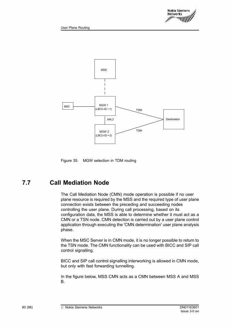
Figure 35. MGW selection in TDM routing
7.7 Call Mediation Node
The Call Mediation Node (CMN) mode operation is possible if no userplane resource is required by the MSS and the required type of user planeconnection exists between the preceding and succeeding nodescontrolling the user plane. During call processing, based on itsconfiguration data, the MSS is able to determine whether it must act as aCMN or a TSN node. CMN detection is carried out by a user plane controlapplication through executing the 'CMN determination' user plane analysisphase.
When the MSC Server is in CMN mode, it is no longer possible to return tothe TSN mode. The CMN functionality can be used with BICC and SIP callcontrol signalling.
BICC and SIP call control signalling interworking is allowed in CMN mode,but only with fast forwarding tunnelling.
In the figure below, MSS CMN acts as a CMN between MSS A and MSSB.
MSS
MGW 1
(LBCU-ID=1)BSC
Destination
TDM
TDM
AAL2
MGW 2
(LBCU-ID=2)
80 (96) # Nokia Siemens Networks DN01163601Issue 3-0 en
User Plane Routing
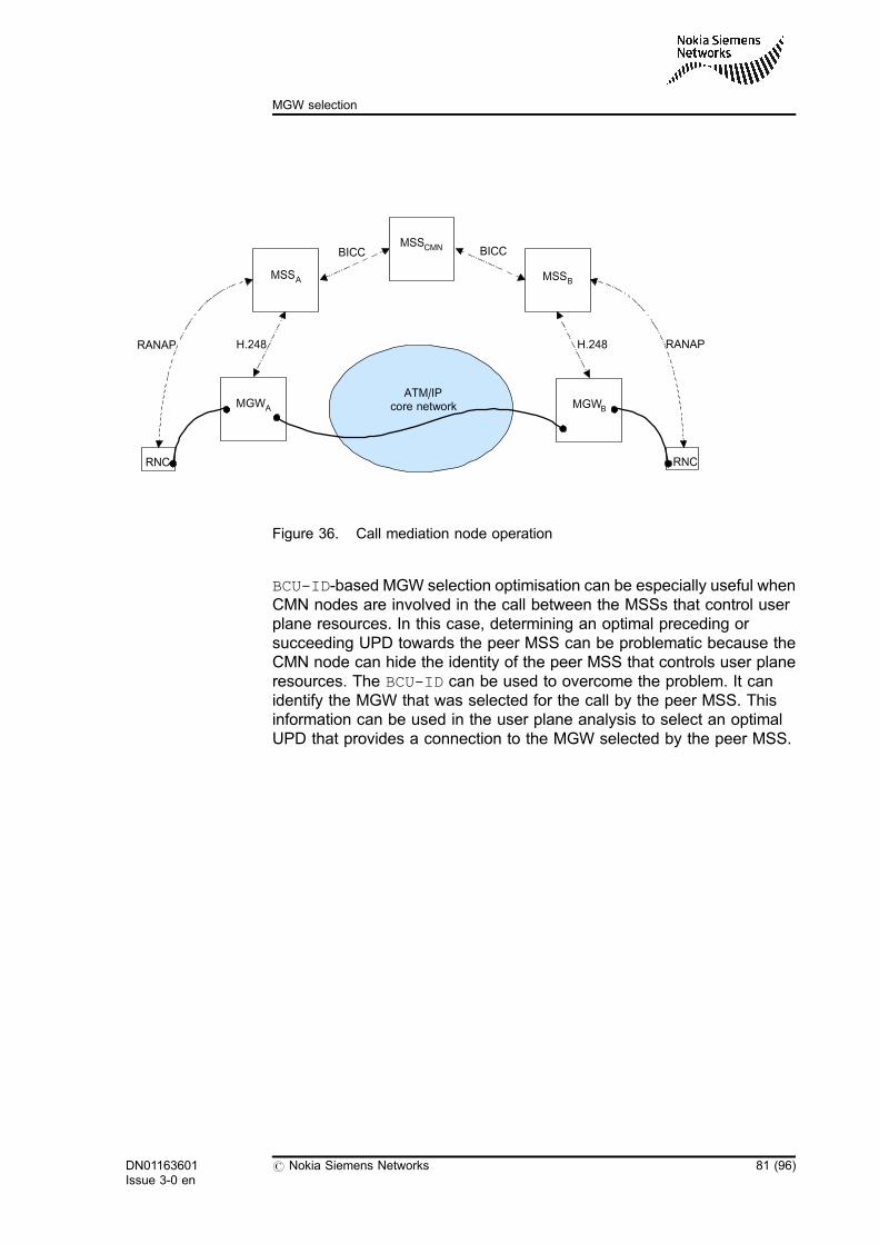
Figure 36. Call mediation node operation
BCU-ID-based MGW selection optimisation can be especially useful whenCMN nodes are involved in the call between the MSSs that control userplane resources. In this case, determining an optimal preceding orsucceeding UPD towards the peer MSS can be problematic because theCMN node can hide the identity of the peer MSS that controls user planeresources. The BCU-ID can be used to overcome the problem. It canidentify the MGW that was selected for the call by the peer MSS. Thisinformation can be used in the user plane analysis to select an optimalUPD that provides a connection to the MGW selected by the peer MSS.
MSSB
MGWA
MSSA
MGWB
RNC
RANAP H.248 H.248
BICC
ATM/IPcore network
RNC
MSSCMN BICC
RANAP
DN01163601Issue 3-0 en
# Nokia Siemens Networks 81 (96)
MGW selection

82 (96) # Nokia Siemens Networks DN01163601Issue 3-0 en
User Plane Routing
8 Interconnecting BNC characteristics
The Interconnecting BNC characteristics load sharing functionality makesit possible to share the traffic load on the connecting Multimedia Gateways(MGWs) between the configured Interconnecting Backbone NetworkConnection (ICBNC) characteristics based on the associated ICBNCCharacteristics (ICBNCC) weights.
With the Interconnecting BNC characteristics exclusion functionality, youcan significantly decrease the amount of unsuccessful calls when the NbUser Plane (Nb UP) protocol initialisation fails since with thisenhancement, it is possible to handle the MGW-MGW interconnecting legindependently as a separate call leg and to make alternativeinterconnecting leg reservation.
8.1 Interconnecting BNC characteristics load sharing
With this enhancement, multiple MGW-MGW interconnecting BackboneNetwork Connection (BNC) values can be associated for one MGW-MGWinterconnecting leg. The traffic load between two MGWs can be sharedamong more ICBNC characteristics.
There are maximum of four possible values as ICBNC characteristics:
. ATM AAL2
. IPv4
. IPv6
. TDM
Additionally, a weight value is associated for each ICBNC characteristicsvalue. The weight value for the ICBNC characteristics ranges from 0 to250.
DN01163601Issue 3-0 en
# Nokia Siemens Networks 83 (96)
Interconnecting BNC characteristics
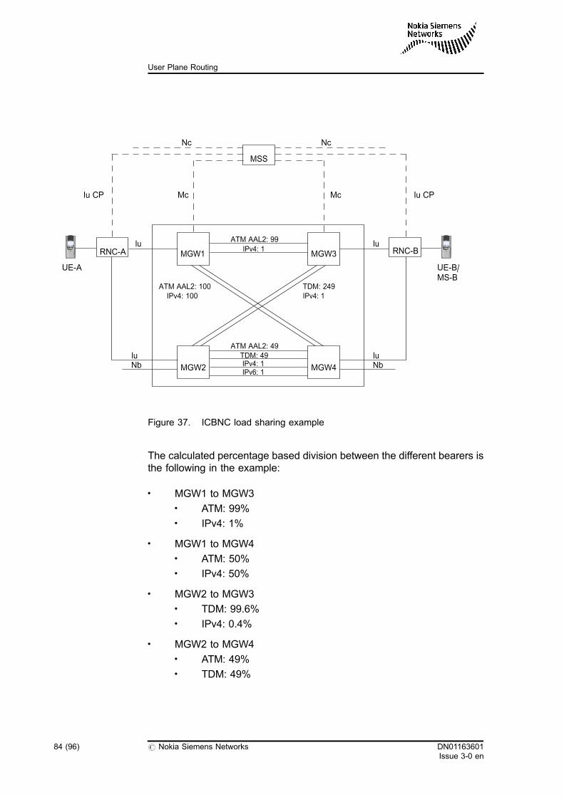
Figure 37. ICBNC load sharing example
The calculated percentage based division between the different bearers isthe following in the example:
. MGW1 to MGW3. ATM: 99%. IPv4: 1%
. MGW1 to MGW4. ATM: 50%. IPv4: 50%
. MGW2 to MGW3. TDM: 99.6%. IPv4: 0.4%
. MGW2 to MGW4. ATM: 49%. TDM: 49%
UE-A UE-B/MS-B
RNC-B
ATM AAL2: 99
IPv4: 1
ATM AAL2: 49
IPv4: 1IPv6: 1
TDM: 49
MGW3
ATM AAL2: 100
IPv4: 100 IPv4: 1
TDM: 249
Nb NbMGW2
MGW1RNC-A
Nc
MSS
Nc
Iu CP Mc Mc Iu CP
Iu
Iu
Iu
Iu
MGW4
84 (96) # Nokia Siemens Networks DN01163601Issue 3-0 en
User Plane Routing
. IPv4: 1%
. IPv6: 1%
The ICBNC characteristics load sharing functionality can be activated foran MGW-MGW ICBNC characteristics selection by using theLOADSHARE value as a result of the interconnecting BNC characteristicsdetermination analysis. For more details, see the User Plane Analysissettings.
When the ICBNC characteristics load sharing functionality is used, theMGW selection happens by applying the User Plane Destination (UPD)load sharing weights first. The ICBNC characteristics weights adjust thetraffic of each backbone network. Thus, you can build more reliable corenetwork. The traffic load is shared between the configured ICBNCcharacteristics based on the associated ICBNC characteristics weights.
With this enhancement, parallel backbone networks can be usedsimultaneously for the same MGW to MGW connection. Additionally, thisfunctionality enables you to share the traffic between different backbonenetworks in a variable ratio, which can be useful during backbonemigration works. You can use one backbone network for the majority of thecalls but the others can use the new backbone network which is under liveverification.
Ext-IP load sharing functionality
The EXTIP_ICBNC PRFILE parameter determines the constantinterconnection BNC characteristics between the MGW to which anExternal Intelligent Peripheral (ext-IP) is connected and the other MGWs.The LOADSHARE parameter value enables load sharing-based ICBNCcharacteristics selection among the available BNC characteristics.
If the EXTIP_ICBNC PRFILE parameter sets the load sharing basedICBNC characteristics selection functionality for Ext-IP services while theICBNC characteristics load sharing feature is not activated, a simplifiedfunctionality works. In case of interconnecting legs for Ext-IP services, theMSC Server (MSS) provides a more flexible and safer functionality forICBNC characteristics selection to ensure that the Ext-IP calls will besuccessful. In this case, the load sharing weights are not configured andboth MGWs have already selected the Ext-IP connected MGW contextand the subscriber MGW. The MSS determines the ICBNC characteristicsamong the possible ICBNC characteristics between the two MGWs. Ifmultiple ICBNC characteristics are configured between the two MGWs,evenly distributed ICBNC characteristics selection is applied.
DN01163601Issue 3-0 en
# Nokia Siemens Networks 85 (96)
Interconnecting BNC characteristics
8.2 Interconnecting BNC characteristics exclusion
With this enhancement, you can significantly decrease the amount ofunsuccessful calls. When the Nb User Plane (Nb UP) protocol initialisationfails because of some backbone network unavailability, the status of thegiven ICBNC characteristics bearer is stored and checked when theICBNC characteristics is selected to be reserved.
When the Nb UP initialisation failure happens on a given ICBNCcharacteristics, a flag is set in the User Plane Topology Database toindicate that the given interconnecting BNC characteristics is currently notavailable. When an interconnecting BNC characteristics is selected forreservation, this availability flag is checked first and the bearer reservationcan happen only if the interconnecting BNC characteristics is available. Ifthe interconnecting BNC characteristics is currently not available, analternative interconnecting BNC characteristics is selected. You canactivate the interconnecting BNC characteristics exclusion functionalitywith the ICBNCC_EXCLUSION PRFILE parameter.
The ICBNC characteristics exclusion functionality cannot be used onMGW-MGW interconnecting legs when the Nokia proprietary Nb' interfaceis used while the Nb' does not use the Nb UP framing protocol.
The ICBNC unavailability status is described by one flag and one counteras a two-level error handling solution. They are stored in the User PlaneTopology Database.
. 'ICBNCC not in use' flag
With the JFS MML command, you can release manually theunavailability flag of the ICBNC characteristics. You can alsoconfigure the timer which can automatically reset the 'ICBNCC not inuse' flag for the faulty ICBNC characteristics. You can set the timerwith the ICBNCC_EXCLUSION_TIMER PRFILE parameter.
. ICBNCC fault count
This counter shows the continuous 'ICBNCC not in use' cases andindicates the permanent fault status.
The highest value of the counter is 7 and it is used as an 'ICBNCCfaulty' flag. This flag indicates that a permanent fault situation hashappened on the ICBNC characteristics, so the ICBNCcharacteristics is marked as faulty ICBNC characteristics.
86 (96) # Nokia Siemens Networks DN01163601Issue 3-0 en
User Plane Routing
If an Nb UP initialisation failure happens several times, the ICBNCCfault counter contains the number of continuously indicated 'ICBNCCnot in use' status. If the maximum allowed ICBNC characteristicsexclusion attempt value is reached, the problem is indicated as apermanent failure. The ICBNCC_EXCLUSION_ATTEMP PRFILEparameter controls the two-level out of service flag behaviour of theICBNC characteristics exclusion functionality. The value of theparameter defines how many attempts are enabled before theICBNC characteristics is marked as faulty.
When the 'ICBNCC faulty' flag is set, no timer is started. You canmake the ICBNC characteristics available only with the JFS MMLcommand.
Alarm 3263 is printed out when one of the ICBNC characteristicsunavailability flags is set. It indicates the network resource outage and theprintout contains details about the faulty ICBNC characteristics (MGW1,MGW2, BNC) and the fault status (fault count value). The alarm subtypeinforms about the ICBNC characteristics fault situation:
Interworking with calls when no load sharing is used
When the load sharing based ICBNC characteristics selection and ICBNCcharacteristics exclusion functionalities are enabled and activated andused in the MSS, the exclusion of the faulty and not used ICBNCcharacteristics are done also for normal calls. If the ICBNC characteristicsdetermination analysis gives an ICBNC characteristics value other thanLOADSHARE, the MGWs which have the selected ICBNC characteristicswith 'ICBNCC not in use' or with 'ICBNCC faulty' flag set are filtered outfrom the MGW candidates. With this enhancement, the ICBNCcharacteristics not available information can be used at normal call casesto avoid unsuccessful interconnecting leg reservation cases.
DN01163601Issue 3-0 en
# Nokia Siemens Networks 87 (96)
Interconnecting BNC characteristics

88 (96) # Nokia Siemens Networks DN01163601Issue 3-0 en
User Plane Routing
9 Traffic separation between the MSS andMGW
With the Traffic separation between the MSS and MGW functionality, youcan create maximum three routes separately for speech and data calls andyou can route the transferred speech and data calls separately betweenthe MSS and the MGW. It can be beneficial if different transportationmethod is used for speech and data calls. It gives the benefit of savingcapacity when the speech is compressed on its route while the data trafficroute remains intact. The differentiation of routes for speech and data callsand the compression of speech calls is beneficial when speech and datacalls go through over large distances and it becomes necessary to enablethe compression of speech calls for capacity reasons. The compressioncan be done by devices of some 3rd party vendors.
The Traffic separation between the MSS and MGW functionality has aneffect on the MSS to MGW interconnecting TDM route selection. Differentroutes for different traffic types are enabled between the MSS and MGW.Three different route types are used on the MSS to MGW interconnectingTDM routes: speech route for speech calls, audio route for TMR=3.1kHzaudio calls, and UDI route for calls using TMR=UDI. Other TMR values aremapped to these three types of routes. For detailed information, see TableCall control logic of forming UPBREQ values in Section User planeanalysis attributes.
Calls with different Transmission Medium Requirement (TMR) are directedto the route with the ideal Transmission Medium Type (TMT). Thus,speech and audio calls can be compressed to save capacity.
You can define three different TDM routes between an MGW and thecontrolling MSS in the MGW database.
DN01163601Issue 3-0 en
# Nokia Siemens Networks 89 (96)
Traffic separation between the MSS and MGW
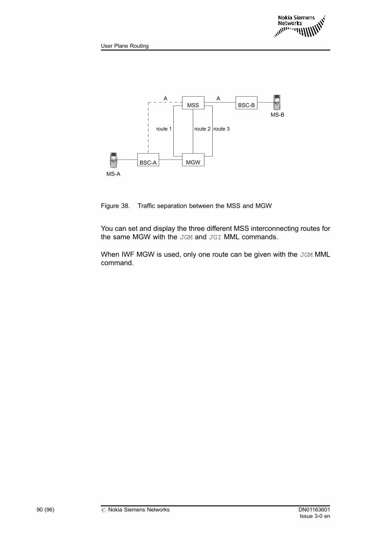
Figure 38. Traffic separation between the MSS and MGW
You can set and display the three different MSS interconnecting routes forthe same MGW with the JGM and JGI MML commands.
When IWF MGW is used, only one route can be given with the JGM MMLcommand.
MS-A
MS-B
BSC-BA
route 1 route 2 route 3
MGW
MSS
BSC-A
A
90 (96) # Nokia Siemens Networks DN01163601Issue 3-0 en
User Plane Routing
10 Alarms and cause codes issued in userplane routing
Alarms related to user plane configuration
. 1259 TOO MANY SUBANALYSES IN USER PLANE ANALYSIS
This disturbance indicates that some analysis chains at the normalside include so many subanalyses that it can decrease the capacityof the switch. The limit of the number of subanalyses to be executedin one chain can be defined with a PRFILE parameter. Thisdisturbance occurs if the number of the executed subanalysesexceeds the value of the corresponding PRFILE parameter value.
. 3178 INFINITE LOOP IN USER PLANE ANALYSIS
This alarm indicates that the execution of the analysis has gonethrough too many subanalyses. It is treated as an analysis loop. Thelimit of the number of subanalyses to be executed in a call case isdefined with a PRFILE parameter. In this case, the limit is (2 *parameter value) + 10. If this alarm occurs, a call which goesthrough a particular subanalysis path is not set up.
. 3179 INTER-CONNECTION BETWEEN TWO MEDIA GATEWAYSIS UNDEFINED
This problem originates from faulty or inadequate configuration. Thisalarm is issued when two MGWs are selected for the call and theuser plane has to be conveyed through them, or if there are nointerconnections defined between the two MGWs.
. 3180 USER PLANE ANALYSIS IS MISSING
The required user plane analysis does not exist. There has to be oneanalysis per phase at the normal side.
DN01163601Issue 3-0 en
# Nokia Siemens Networks 91 (96)
Alarms and cause codes issued in user plane routing
. 3185 USER PLANE CONTROL IS UNABLE TO RESOLVE USERPLANE DEST. DATA
The problem originates from faulty or inadequate configuration. Thisalarm is set in the following cases:. The 'preceding UPD determination' or the 'succeeding UPD
determination' user plane analysis phase determines a wrongvalue for the UPD.
. The UPD data is not defined in the topology database.
. 3263 CALL ESTABLISHMENT FAILURE IN USER PLANECONTROL
This alarm indicates the different configuration problems related touser plane-level routing.
Alarms related to user plane topology database
. 0018 DATABASE RECOVERY IS IN PROGRESS
Recovery based on an event log is in progress in the managementsystem of the database.
. 0660 DATABASE TRANSACTIONS OR DISK UPDATESPREVENTED
Database transactions or disk updates are prevented in thedatabase management system.
. 1661 DATABASE MANAGER IN FATAL ERROR STATE
An error occurred in the database management system, and thesystem has been set to the 'fatal error' state. In the 'fatal error' statethe management system program block does not accept supervisionmessages. In this case, the system resets the database unit.
. 1662 DATABASE LOADING ERROR
The loading of the database fails. If several load attempts fail, themanagement system is set to the 'fatal error' state. Because of this,the system resets the database unit.
. 1663 HAND RESERVATION ERROR IN DATABASE MANAGER
The reservation of a transaction or fastread hand fails in thedatabase management system.
. 1664 ERROR IN DATABASE SYSTEM
An error occurred in the database management system during theoperation of a database procedure.
92 (96) # Nokia Siemens Networks DN01163601Issue 3-0 en
User Plane Routing
. 2259 DATABASE IS INCONSISTENT
Inconsistencies have been found in the database during databaseintegrity checking. Because of these faults the functioning of thedatabase may be disturbed.
. 2261 NO CONSISTENT COPY OF DATABASE ON DISK
Neither of the disks has a consistent copy of the database. If there isa properly functioning copy of the database in the memory, theoperation of the system is not in immediate danger. However, if thecopy of the database is lost from the memory, the fault situation mayprevent the restart of the database.
. 2397 DATABASE FILE IS IN DANGER TO GET FULL
The threshold of the capacity of a database file has been exceeded.
. 2399 DATABASE DISK UPDATES ARE PREVENTED
Database disk updates have been prevented with an MMLcommand. The database disk copy is not updated. Updates saved inthe memory can be lost if the system is restarted.
. 2663 DUMPING ERROR IN DATABASE MANAGER
The dumping of a database fails in the database managementsystem.
. 2664 DATABASE COPY STAYS INCONSISTENT ON SAME DISK
Database disk updating is based on one disk. Even if the other diskcontains a consistent copy of the database, in the case of a failure,the two copies might be inconsistent.
. 2268 DATABASE BACKUP PROCESS IS TERMINATED
Taking a backup of the database has lasted too long, and themanagement system terminates the process.
. 2447 DATABASE TRANSACTION SAVING FAILED
The database events performed by the database managementsystem have been defined to be recorded in an event log with aparameter in the DBPARA file. The database management systemsets this alarm if it cannot contact the event log managementprogram block when it tries to start recording events. In this case, thesystem cannot record data that is necessary for database recoveryand in an error situation the state of the database cannot be restoredas accurately as when database events have been recorded
DN01163601Issue 3-0 en
# Nokia Siemens Networks 93 (96)
Alarms and cause codes issued in user plane routing
successfully. If the system cannot record database events in theevent log, the state of the database can only be restored to the levelof the previous backup copy. Updates that have taken place afterbackup copying cannot be reloaded to the database.
. 2662 NO CONSISTENT DATABASE ANYWHERE
Neither disk has a consistent copy of the database, and thedatabase management system fails in trying to load the databasefrom a disk. The database cannot be used.
. 2665 DATABASE LOG BUFFER SIZE ERROR
This is an internal error in the database management system. TheDisk Updating System Management program block (DBSMAN)thinks there is an error in the size of the database log buffer. In theinitialisation phase of the DBSMAN a log buffer is deemed faulty if itis smaller than the minimum size, and also when the size of the workfile designated for handling the log buffer is smaller than that of thelog buffer. After the initialisation, a possible error is detected whenthe family handling the database, DBMANA, requests the DBSMANto transfer to the disk log a log buffer whose length is different fromwhich the DBSMAN can handle. The error prevents databaseupdating on the disk. Automatic recovery measures are taken; eitherthe unit that contains the DBSMAN, or the one that has theDBMANA, or both of them are restarted. In addition to this, it ispossible to modify the DBPARA and the DBINFO files on the disk.
. 3069 DATABASE REMOTE COPY UPDATING PREVENTED
The database management system of the database primary copysets this alarm when remote copy updating has been prevented bythe DBT MML command. When this alarm is on, updates to thedatabase primary copy are done but the delivery of those updates tothe remote copy is prevented. This means that the data in the remotecopy is inconsistent with the data in the primary copy. However,updates that must be delivered to the database remote copy arecached and when the remote copy updating is resumed again withthe DBT MML command, the updates are delivered to the remotecopy and the remote copy is consistent with the primary copy. Thereasonable time for the duration of preventing remote copy updatingdepends on the database in question and the application which usesit. For example, if there are plenty of updates to the databaseprimary copy and the application in the remote unit needs to read up-to-date information from the remote copy, the updating of the remotecopy should be prevented for as short an interval as possible.
. 3070 DATABASE REMOTE COPY LOADING FAILED
94 (96) # Nokia Siemens Networks DN01163601Issue 3-0 en
User Plane Routing
Loading of the database remote copy failed from the unit shown inthe additional information of the alarm. The remote copy is notavailable in the object unit of the alarm. The reason for the remotecopy load failure can be, for example, that the database manager ofthe main database is not ready to receive service requests or thatthe unit that contains the main database is not functioning properly.
Cause codes
. call_interrupt_in_up_ana
This cause code is set when the user plane analysis results instopping the call result.
When the user plane analysis results in stopping the call result, theURQPRB returns this cause code in a negative resource reservationacknowledgement.
. cd_t_configuration_error
This cause code is set in several cases when the systemconfiguration is inadequate to complete the calls. The followingcases are possible:. MGW is not correctly configured in the MGW database.. Topology database could not provide a reasonable value.. Virtual circuit conversion to MGW-PCM/TSL combination is
unsuccessful.. No MGW with an interconnecting TDM is configured in the
MGW database despite the need for them.. Incorrect bearer establishment method is configured in the
user plane analysis.. Incorrect controlling CCSU/SIGU unit information is stored in
the MGW database.. Bearer network connection type (BNC characteristics) defined
by the operator is unknown.. Bearer network connection type (BNC characteristics) defined
in the 'succeeding BNC characteristics' user plane analysisphase is contradictory to the value defined in the UPD.
. resource_not_avail_in_cmn
This problem occurs only in CMN mode. This cause code is set if theMSC server is functioning as a CMN and either signalling or the callcontrol requires the reservation of user plane resources for a call.
. undefined_inter_connection
DN01163601Issue 3-0 en
# Nokia Siemens Networks 95 (96)
Alarms and cause codes issued in user plane routing
This cause code is set if there are no interconnections definedbetween two MGWs and a user plane should be conveyed throughthem.
. unknown_user_plane_destination
This cause code is set if the 'preceding UPD determination' or the'succeeding UPD determination' user plane analysis phases lead toan unknown result, or if user plane destination data is not defined inthe topology database.
. user_plane_ana_problem
This cause code is set if some part of user plane analysis isundefined, or if the structure of the user plane analysis isinconsistent.
For more information, see Clear Code List.
96 (96) # Nokia Siemens Networks DN01163601Issue 3-0 en
User Plane Routing