Embed Size (px)
Citation preview

Contents 1
USER MANUAL
ProCapture-X
Version: 1.1
Date: June 2017

About This Manual
This manual introduces the operation of user interfaces and menu
functions of ProCapture-X Access Control terminal.
The pictures in this manual may not be exactly consistent with those of
your product; the actual product's display shall prevail.
Not all the devices have the function with ★, the real product prevails.
Contents I
Contents 1 Guidance Notes ..................................................................................................................................................................... 1
1.1 Method of Pressing Fingerprint ......................................................................................................................... 1
1.2 Verification Modes ................................................................................................................................................... 2
1.2.1 1:N Fingerprint Verification ........................................................................................................... 2 1.2.2 1:1 Fingerprint Verification ............................................................................................................ 2 1.2.3 Password Verification ...................................................................................................................... 3 1.2.4 Card Verification★ ........................................................................................................................... 4
1.3 Initial Interface .......................................................................................................................................................... 4
2 Main Menu ............................................................................................................................................................................... 5
3 Date/Time Settings ............................................................................................................................................................... 7
3.1 Daylight Saving Time ............................................................................................................................................. 7
4 User Management ................................................................................................................................................................ 9
4.1 Adding User ............................................................................................................................................................... 9
4.2 Setting Access Control ........................................................................................................................................ 10
4.3 Searching User ....................................................................................................................................................... 10
4.4 Editing User ............................................................................................................................................................. 11
4.5 Deleting a User ...................................................................................................................................................... 11
4.6 User Display Style ................................................................................................................................................. 12
5 User Role ................................................................................................................................................................................ 13
5.1 Enabling User Role ............................................................................................................................................... 13
5.2 Input User Role Name ......................................................................................................................................... 13
5.3 Rights Allocation ................................................................................................................................................... 14
6 Comm. Settings .................................................................................................................................................................. 15
6.1 Ethernet Settings .................................................................................................................................................. 15
6.2 Serial Comm. Settings ......................................................................................................................................... 15
6.3 PC Connection ....................................................................................................................................................... 16
6.4 Wireless Network★ ............................................................................................................................................. 17
6.5 Cloud Server Settings .......................................................................................................................................... 19
6.5.1 ADMS ................................................................................................................................................... 19
6.6 Wiegand Setup ...................................................................................................................................................... 20
II User Manual for ProCapture-X
6.6.1 Wiegand Input ................................................................................................................................. 20 6.6.2 Wiegand Output ............................................................................................................................. 22 6.6.3 Card Format Detect Automatically ........................................................................................... 23
7 Access Control ..................................................................................................................................................................... 25
7.1 Access Control Options Settings ..................................................................................................................... 25
7.2 Time Rule Settings ................................................................................................................................................ 27
7.3 Holidays Settings .................................................................................................................................................. 29
7.3.1 Adding Holiday ................................................................................................................................ 30 7.3.2 All Holidays........................................................................................................................................ 31
7.4 Combined Verification Settings ........................................................................................................................ 31
7.5 Anti-passback Settings ....................................................................................................................................... 33
8 System Settings .................................................................................................................................................................. 35
8.1 Access Logs Settings............................................................................................................................................ 35
8.2 Fingerprint Parameters ....................................................................................................................................... 36
8.3 Reset to Factory Settings ................................................................................................................................... 37
8.4 USB Upgrade .......................................................................................................................................................... 38
9 Personalize Settings .......................................................................................................................................................... 40
9.1 User Interface Settings ........................................................................................................................................ 40
9.2 Voice Settings ......................................................................................................................................................... 41
9.3 Bells Settings .......................................................................................................................................................... 41
9.3.1 Adding New Bell .............................................................................................................................. 41 9.3.2 Editing a Bell ..................................................................................................................................... 42 9.3.3 Deleting a Bell .................................................................................................................................. 42
10 Data Mgt. ............................................................................................................................................................................ 43
10.1 Deleting Data ....................................................................................................................................................... 43
10.2 Data Backup ......................................................................................................................................................... 43
10.3 Data Restoration ................................................................................................................................................. 44
11 IC Card★ ............................................................................................................................................................................. 45
11.1 Enroll as ID card ................................................................................................................................................... 45
11.2 Enroll as Fingerprint Card ................................................................................................................................ 46
11.3 Clean Card Data .................................................................................................................................................. 47
11.4 Copy Card Data ................................................................................................................................................... 47

Contents III
11.5 IC Card Options ................................................................................................................................................... 48
12 USB Manager ..................................................................................................................................................................... 50
12.1 USB Download..................................................................................................................................................... 50
12.2 USB Upload ........................................................................................................................................................... 50
13 Attendance Search .......................................................................................................................................................... 52
14 Autotest............................................................................................................................................................................... 53
15 System Information ........................................................................................................................................................ 54
16 Troubleshooting .............................................................................................................................................................. 55
17 Appendices ........................................................................................................................................................................ 56
17.1 Text Input Operation Instructions ................................................................................................................ 56
17.2 Photo ID Function★ ......................................................................................................................................... 57
17.3 Wiegand Introduction ...................................................................................................................................... 57
17.4 Image Uploading Rule ...................................................................................................................................... 58
17.5 Statement on Human Rights and Privacy ................................................................................................. 60
17.6 Environment-Friendly Use Description ...................................................................................................... 62
Guidance Notes 1
1 Guidance Notes
1.1 Method of Pressing Fingerprint
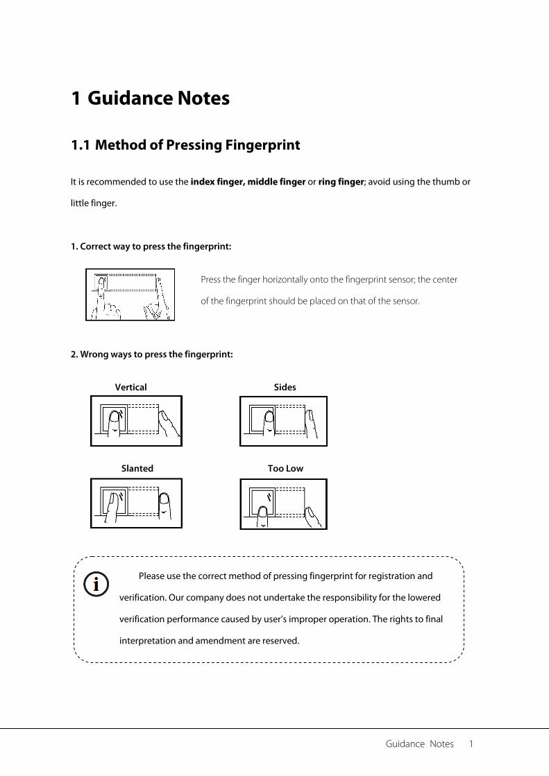
It is recommended to use the index finger, middle finger or ring finger; avoid using the thumb or
little finger.
1. Correct way to press the fingerprint:
2. Wrong ways to press the fingerprint:
Press the finger horizontally onto the fingerprint sensor; the center
of the fingerprint should be placed on that of the sensor.
Vertical
Sides
Slanted Too Low
Please use the correct method of pressing fingerprint for registration and
verification. Our company does not undertake the responsibility for the lowered
verification performance caused by user’s improper operation. The rights to final
interpretation and amendment are reserved.
2 User Manual for ProCapture-X
1.2 Verification Modes
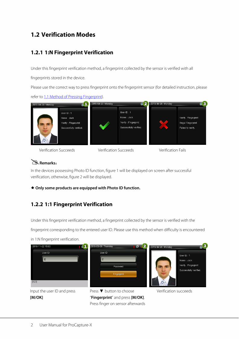
1.2.1 1:N Fingerprint Verification
Under this fingerprint verification method, a fingerprint collected by the sensor is verified with all
fingerprints stored in the device.
Please use the correct way to press fingerprint onto the fingerprint sensor (for detailed instruction, please
refer to 1.1 Method of Pressing Fingerprint).
Verification Succeeds Verification Succeeds Verification Fails
Remarks:
In the devices possessing Photo ID function, figure 1 will be displayed on screen after successful verification, otherwise, figure 2 will be displayed.
Only some products are equipped with Photo ID function.
1.2.2 1:1 Fingerprint Verification
Under this fingerprint verification method, a fingerprint collected by the sensor is verified with the
fingerprint corresponding to the entered user ID. Please use this method when difficulty is encountered
in 1:N fingerprint verification.
Input the user ID and press
[M/OK]
Press ▼ button to choose
“Fingerprint” and press [M/OK]. Press finger on sensor afterwards
Verification succeeds
Guidance Notes 3
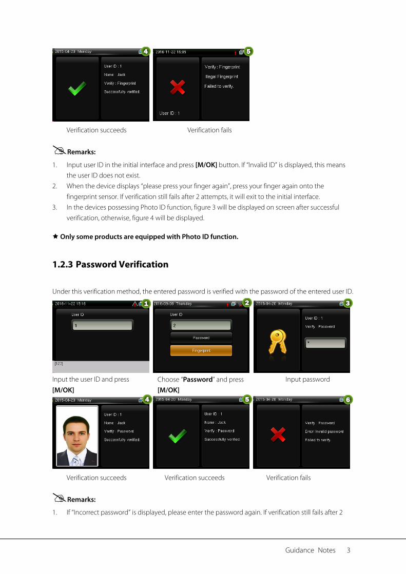
Verification succeeds Verification fails
Remarks:
1. Input user ID in the initial interface and press [M/OK] button. If “Invalid ID” is displayed, this means the user ID does not exist.
2. When the device displays “please press your finger again”, press your finger again onto the fingerprint sensor. If verification still fails after 2 attempts, it will exit to the initial interface.
3. In the devices possessing Photo ID function, figure 3 will be displayed on screen after successful verification, otherwise, figure 4 will be displayed.
Only some products are equipped with Photo ID function.
1.2.3 Password Verification
Under this verification method, the entered password is verified with the password of the entered user ID.
Input the user ID and press
[M/OK] Choose “Password” and press [M/OK]
Input password
Verification succeeds Verification succeeds Verification fails
Remarks:
1. If “Incorrect password” is displayed, please enter the password again. If verification still fails after 2
4 User Manual for ProCapture-X
attempts, it will exit to the initial interface. 2. In the devices possessing Photo ID function, figure 4 will be displayed on screen after successful
verification, otherwise, figure 5 will be displayed.
Only some products are equipped with Photo ID function.
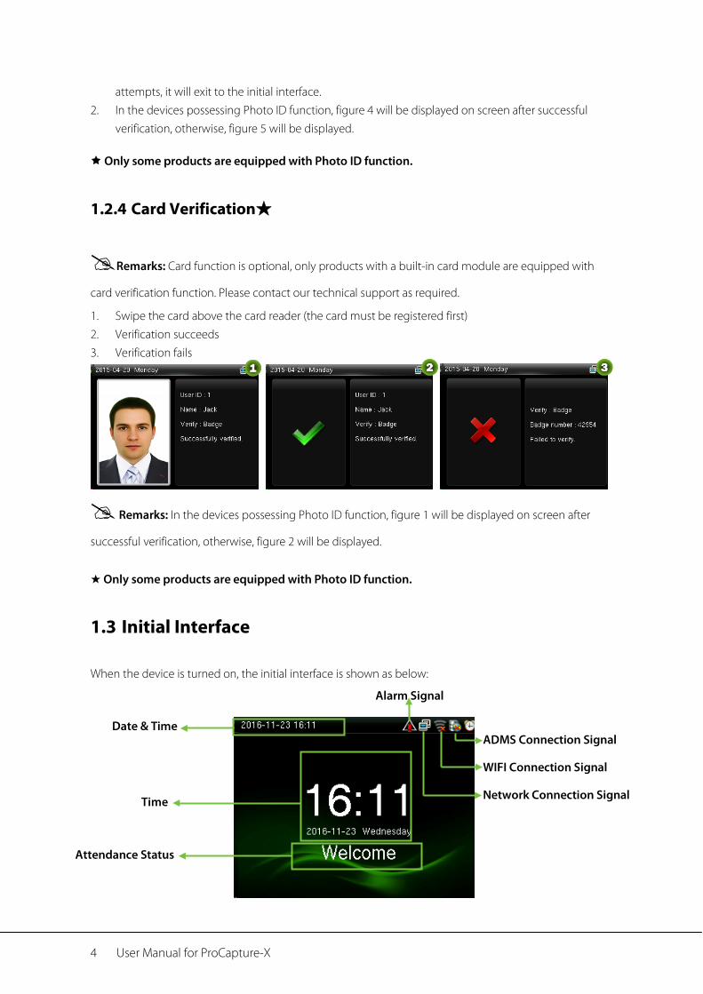
1.2.4 Card Verification★
Remarks: Card function is optional, only products with a built-in card module are equipped with
card verification function. Please contact our technical support as required.
1. Swipe the card above the card reader (the card must be registered first) 2. Verification succeeds 3. Verification fails
Remarks: In the devices possessing Photo ID function, figure 1 will be displayed on screen after
successful verification, otherwise, figure 2 will be displayed.
★ Only some products are equipped with Photo ID function.
1.3 Initial Interface
When the device is turned on, the initial interface is shown as below:
Date & Time
Alarm Signal
ADMS Connection Signal
WIFI Connection Signal
Network Connection Signal
Time
Attendance Status
Main Menu 5
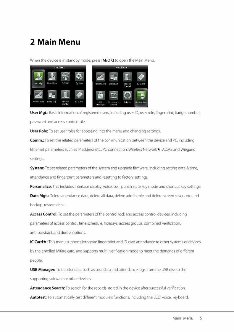
2 Main Menu
When the device is in standby mode, press [M/OK] to open the Main Menu.
User Mgt.: Basic information of registered users, including user ID, user role, fingerprint, badge number,
password and access control role.
User Role: To set user roles for accessing into the menu and changing settings.
Comm.: To set the related parameters of the communication between the device and PC, including
Ethernet parameters such as IP address etc., PC connection, Wireless Network, ADMS and Wiegand
settings.
System: To set related parameters of the system and upgrade firmware, including setting date & time,
attendance and fingerprint parameters and resetting to factory settings.
Personalize: This includes interface display, voice, bell, punch state key mode and shortcut key settings.
Data Mgt.: Delete attendance data, delete all data, delete admin role and delete screen savers etc. and
backup, restore data.
Access Control: To set the parameters of the control lock and access control devices, including
parameters of access control, time schedule, holidays, access groups, combined verification,
anti-passback and duress options.
IC Card: This menu supports integrate fingerprint and ID card attendance to other systems or devices
by the enrolled Mifare card, and supports multi- verification mode to meet the demands of different
people.
USB Manager: To transfer data such as user data and attendance logs from the USB disk to the
supporting software or other devices.
Attendance Search: To search for the records stored in the device after successful verification.
Autotest: To automatically test different module’s functions, including the LCD, voice, keyboard,

6 User Manual for ProCapture-X
fingerprint sensor and clock RTC test.
System Info: To check device capacity, device and firmware information.
Date/Time Settings 7
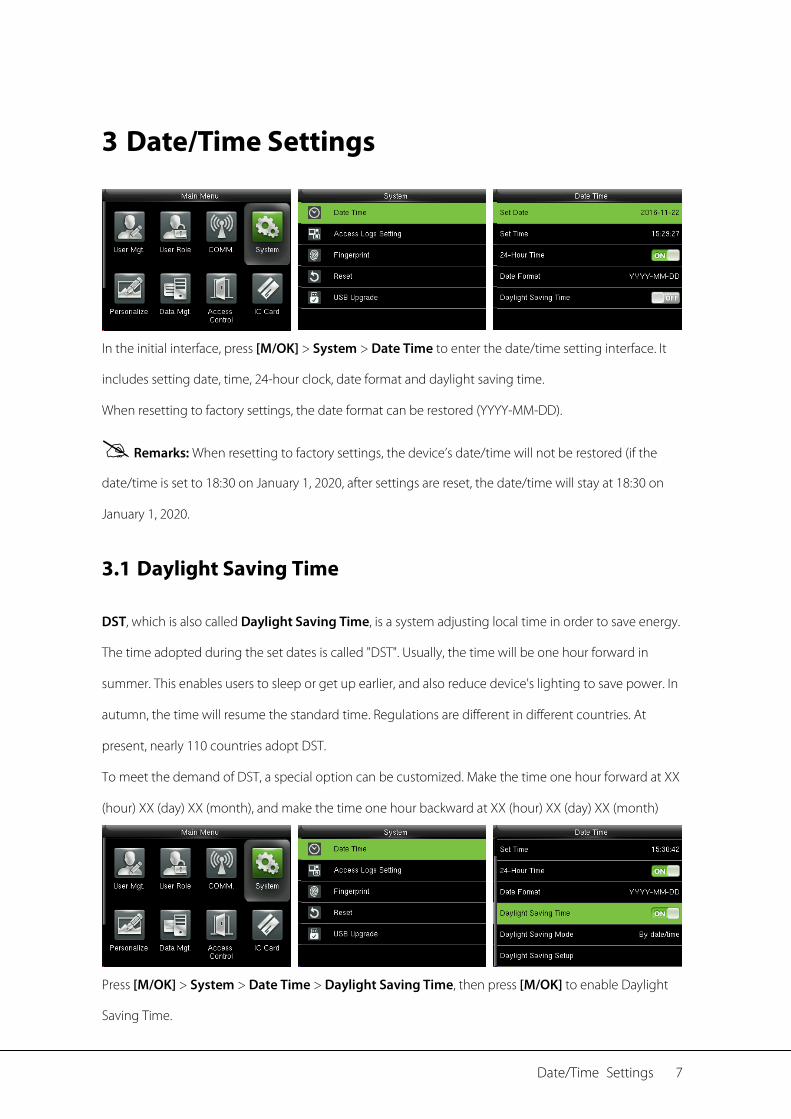
3 Date/Time Settings
In the initial interface, press [M/OK] > System > Date Time to enter the date/time setting interface. It
includes setting date, time, 24-hour clock, date format and daylight saving time.
When resetting to factory settings, the date format can be restored (YYYY-MM-DD).
Remarks: When resetting to factory settings, the device’s date/time will not be restored (if the
date/time is set to 18:30 on January 1, 2020, after settings are reset, the date/time will stay at 18:30 on
January 1, 2020.
3.1 Daylight Saving Time
DST, which is also called Daylight Saving Time, is a system adjusting local time in order to save energy.
The time adopted during the set dates is called "DST". Usually, the time will be one hour forward in
summer. This enables users to sleep or get up earlier, and also reduce device's lighting to save power. In
autumn, the time will resume the standard time. Regulations are different in different countries. At
present, nearly 110 countries adopt DST.
To meet the demand of DST, a special option can be customized. Make the time one hour forward at XX
(hour) XX (day) XX (month), and make the time one hour backward at XX (hour) XX (day) XX (month)
Press [M/OK] > System > Date Time > Daylight Saving Time, then press [M/OK] to enable Daylight
Saving Time.
8 User Manual for ProCapture-X
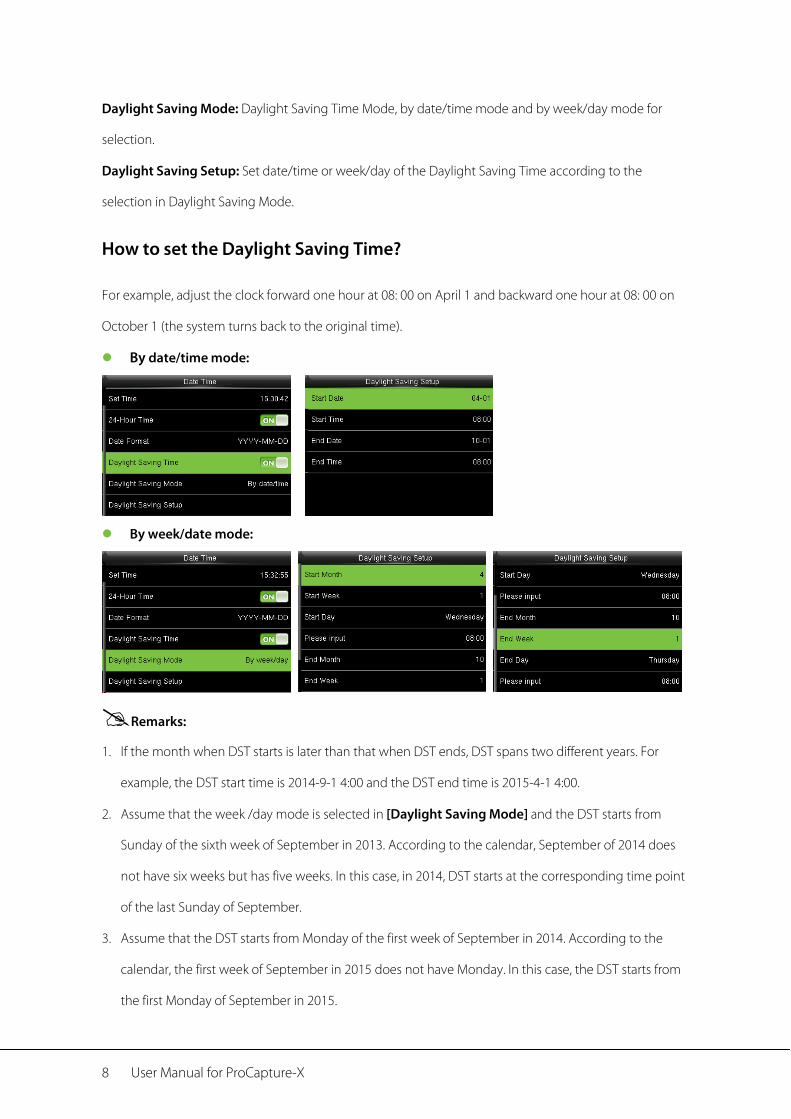
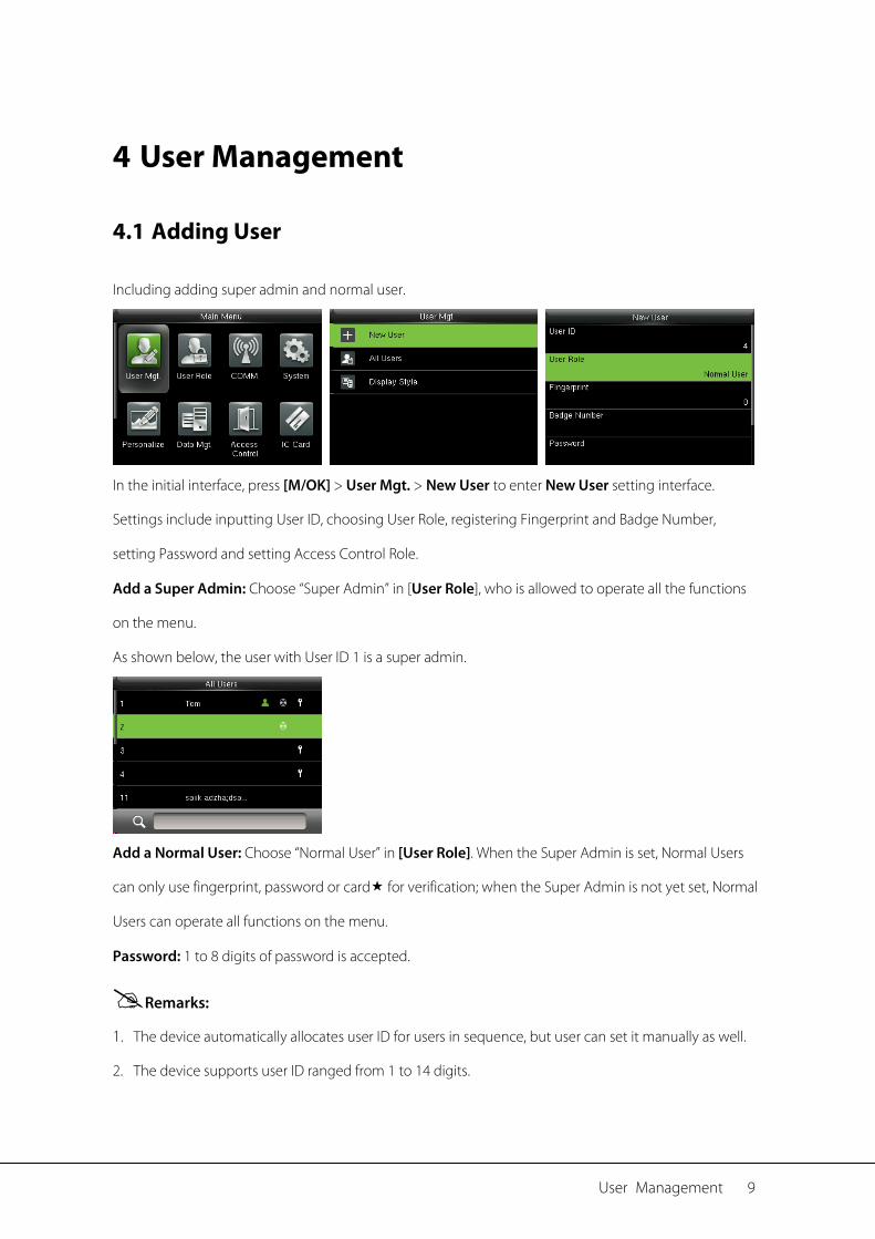
Daylight Saving Mode: Daylight Saving Time Mode, by date/time mode and by week/day mode for
selection.
Daylight Saving Setup: Set date/time or week/day of the Daylight Saving Time according to the
selection in Daylight Saving Mode.
How to set the Daylight Saving Time?
For example, adjust the clock forward one hour at 08: 00 on April 1 and backward one hour at 08: 00 on
October 1 (the system turns back to the original time).
By date/time mode:
By week/date mode:
Remarks:
1. If the month when DST starts is later than that when DST ends, DST spans two different years. For
example, the DST start time is 2014-9-1 4:00 and the DST end time is 2015-4-1 4:00.
2. Assume that the week /day mode is selected in [Daylight Saving Mode] and the DST starts from
Sunday of the sixth week of September in 2013. According to the calendar, September of 2014 does
not have six weeks but has five weeks. In this case, in 2014, DST starts at the corresponding time point
of the last Sunday of September.
3. Assume that the DST starts from Monday of the first week of September in 2014. According to the
calendar, the first week of September in 2015 does not have Monday. In this case, the DST starts from
the first Monday of September in 2015.
User Management 9
4 User Management
4.1 Adding User
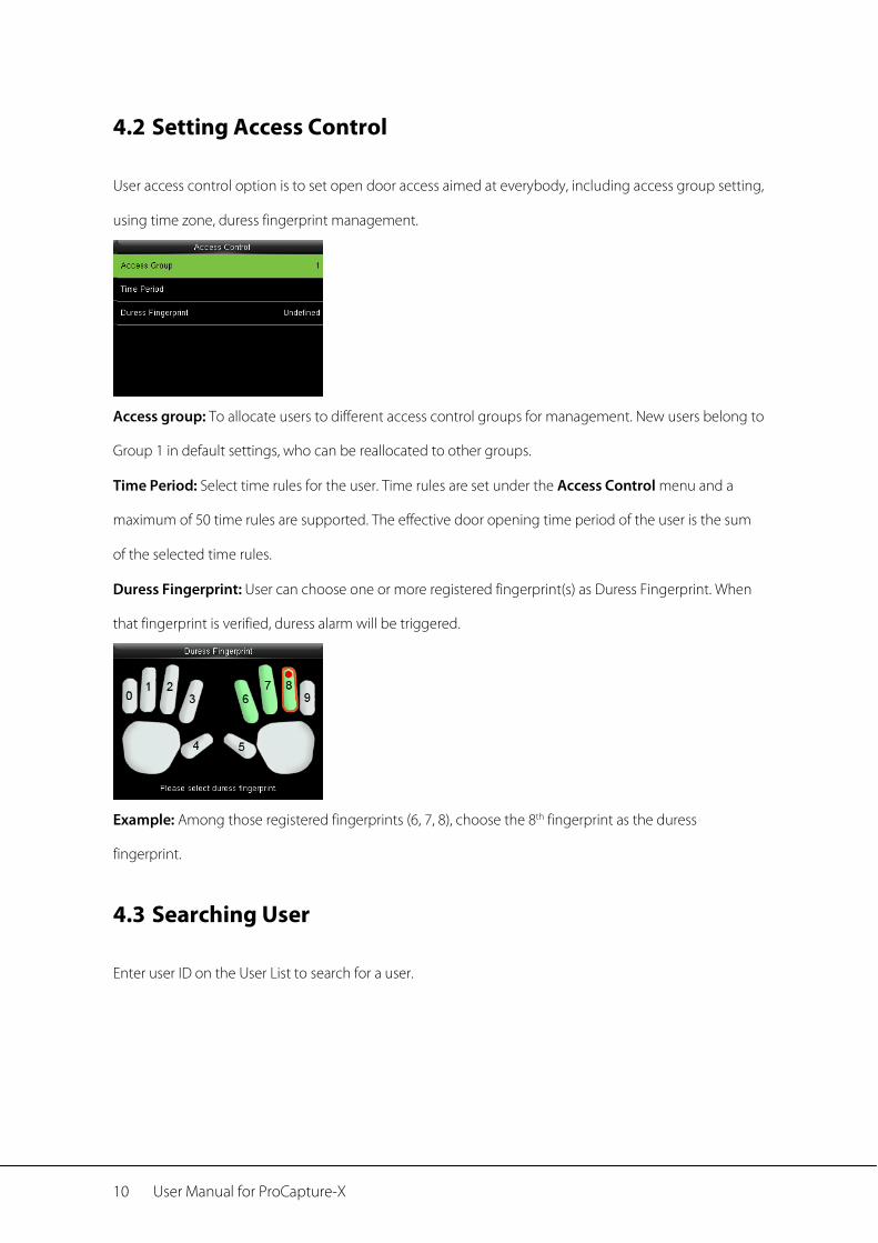
Including adding super admin and normal user.
In the initial interface, press [M/OK] > User Mgt. > New User to enter New User setting interface.
Settings include inputting User ID, choosing User Role, registering Fingerprint and Badge Number,
setting Password and setting Access Control Role.
Add a Super Admin: Choose “Super Admin” in [User Role], who is allowed to operate all the functions
on the menu.
As shown below, the user with User ID 1 is a super admin.
Add a Normal User: Choose “Normal User” in [User Role]. When the Super Admin is set, Normal Users
can only use fingerprint, password or card for verification; when the Super Admin is not yet set, Normal
Users can operate all functions on the menu.
Password: 1 to 8 digits of password is accepted.
Remarks:
1. The device automatically allocates user ID for users in sequence, but user can set it manually as well.
2. The device supports user ID ranged from 1 to 14 digits.
10 User Manual for ProCapture-X
4.2 Setting Access Control
User access control option is to set open door access aimed at everybody, including access group setting,
using time zone, duress fingerprint management.
Access group: To allocate users to different access control groups for management. New users belong to
Group 1 in default settings, who can be reallocated to other groups.
Time Period: Select time rules for the user. Time rules are set under the Access Control menu and a
maximum of 50 time rules are supported. The effective door opening time period of the user is the sum
of the selected time rules.
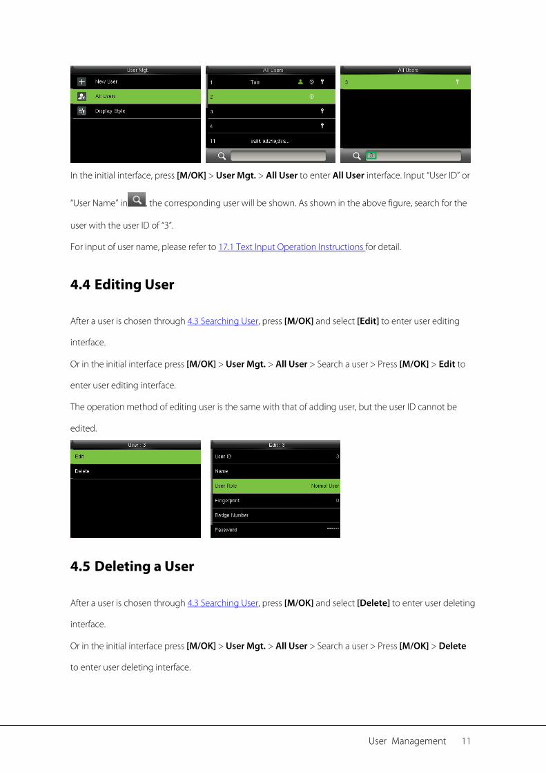
Duress Fingerprint: User can choose one or more registered fingerprint(s) as Duress Fingerprint. When
that fingerprint is verified, duress alarm will be triggered.
Example: Among those registered fingerprints (6, 7, 8), choose the 8th fingerprint as the duress
fingerprint.
4.3 Searching User
Enter user ID on the User List to search for a user.
User Management 11
In the initial interface, press [M/OK] > User Mgt. > All User to enter All User interface. Input “User ID” or
“User Name” in , the corresponding user will be shown. As shown in the above figure, search for the
user with the user ID of “3”.
For input of user name, please refer to 17.1 Text Input Operation Instructions for detail.
4.4 Editing User
After a user is chosen through 4.3 Searching User, press [M/OK] and select [Edit] to enter user editing
interface.
Or in the initial interface press [M/OK] > User Mgt. > All User > Search a user > Press [M/OK] > Edit to
enter user editing interface.
The operation method of editing user is the same with that of adding user, but the user ID cannot be
edited.
4.5 Deleting a User
After a user is chosen through 4.3 Searching User, press [M/OK] and select [Delete] to enter user deleting
interface.
Or in the initial interface press [M/OK] > User Mgt. > All User > Search a user > Press [M/OK] > Delete
to enter user deleting interface.
12 User Manual for ProCapture-X
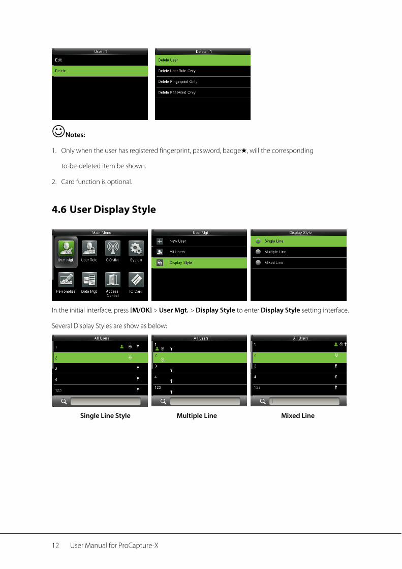
Notes:
1. Only when the user has registered fingerprint, password, badge★, will the corresponding
to-be-deleted item be shown.
2. Card function is optional.
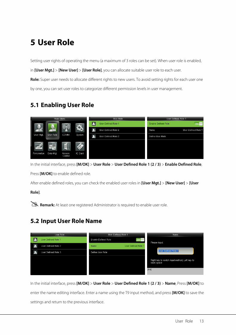
4.6 User Display Style
In the initial interface, press [M/OK] > User Mgt. > Display Style to enter Display Style setting interface.
Several Display Styles are show as below:
Single Line Style Multiple Line Mixed Line
User Role 13
5 User Role
Setting user rights of operating the menu (a maximum of 3 roles can be set). When user role is enabled,
in [User Mgt.] > [New User] > [User Role], you can allocate suitable user role to each user.
Role: Super user needs to allocate different rights to new users. To avoid setting rights for each user one
by one, you can set user roles to categorize different permission levels in user management.
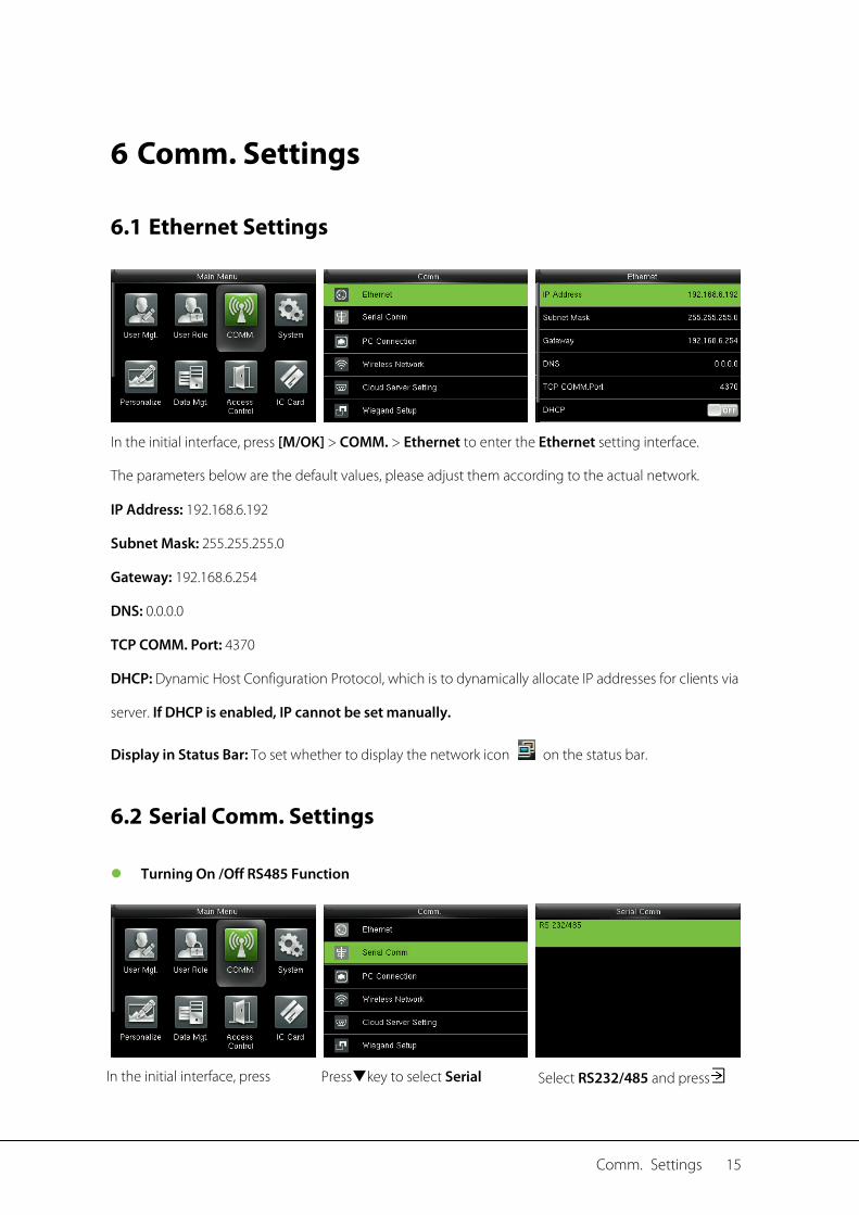
5.1 Enabling User Role
In the initial interface, press [M/OK] > User Role > User Defined Role 1 (2 / 3) > Enable Defined Role,
Press [M/OK] to enable defined role.
After enable defined roles, you can check the enabled user roles in [User Mgt.] > [New User] > [User
Role].
Remark: At least one registered Administrator is required to enable user role.
5.2 Input User Role Name
In the initial interface, press [M/OK] > User Role > User Defined Role 1 (2 / 3) > Name, Press [M/OK] to
enter the name editing interface. Enter a name using the T9 input method, and press [M/OK] to save the
settings and return to the previous interface.

14 User Manual for ProCapture-X
For detailed about how to enter a name, see 17.1 Text Input Operation Instructions.
5.3 Rights Allocation
In the initial interface, press [M/OK] > User Role > User Defined Role 1 (2 / 3) > Define User Role to
enter User Defined Role 1 (2 /3) rights allocating interface. Press [M/OK] to select or cancel the
operating right to each menu for User Defined Role 1 (2 /3).
Comm. Settings 15
6 Comm. Settings
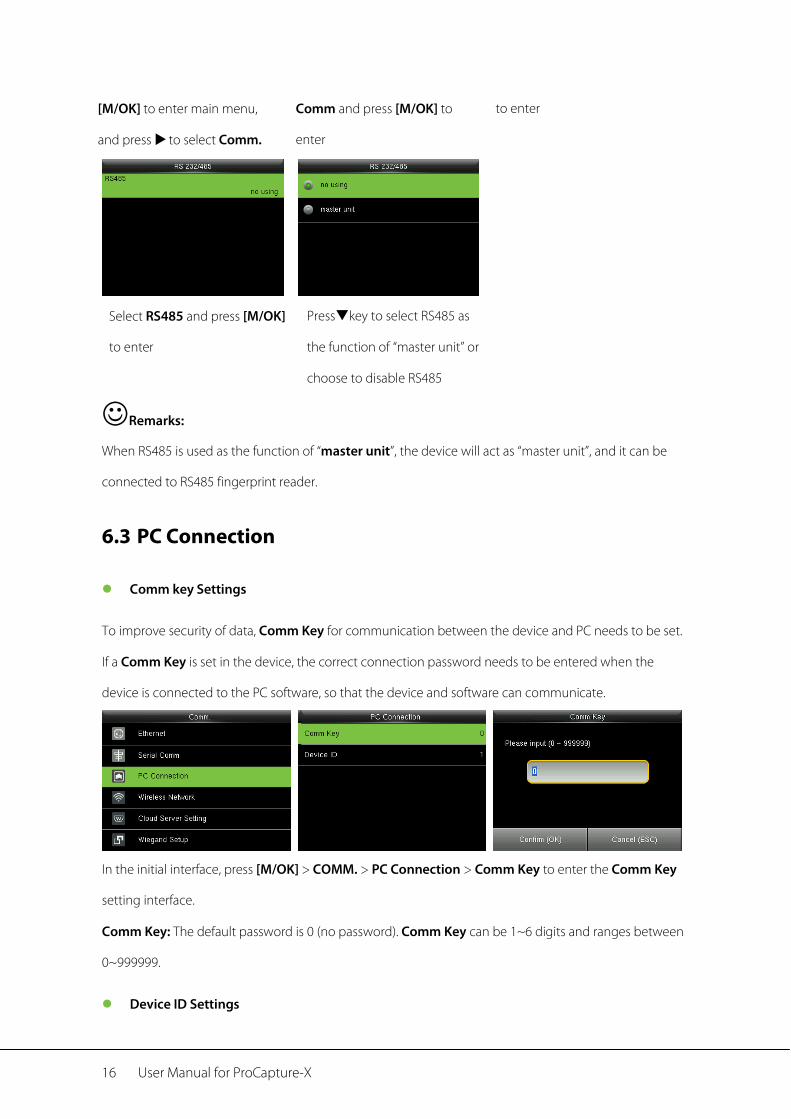
6.1 Ethernet Settings
In the initial interface, press [M/OK] > COMM. > Ethernet to enter the Ethernet setting interface.
The parameters below are the default values, please adjust them according to the actual network.
IP Address: 192.168.6.192
Subnet Mask: 255.255.255.0
Gateway: 192.168.6.254
DNS: 0.0.0.0
TCP COMM. Port: 4370
DHCP: Dynamic Host Configuration Protocol, which is to dynamically allocate IP addresses for clients via
server. If DHCP is enabled, IP cannot be set manually.
Display in Status Bar: To set whether to display the network icon on the status bar.
6.2 Serial Comm. Settings
Turning On /Off RS485 Function
In the initial interface, press Presskey to select Serial Select RS232/485 and press
16 User Manual for ProCapture-X
[M/OK] to enter main menu,
and press to select Comm.
Comm and press [M/OK] to
enter
to enter
Select RS485 and press [M/OK]
to enter
Presskey to select RS485 as
the function of “master unit” or
choose to disable RS485
Remarks:
When RS485 is used as the function of “master unit”, the device will act as “master unit”, and it can be
connected to RS485 fingerprint reader.
6.3 PC Connection
Comm key Settings
To improve security of data, Comm Key for communication between the device and PC needs to be set.
If a Comm Key is set in the device, the correct connection password needs to be entered when the
device is connected to the PC software, so that the device and software can communicate.
In the initial interface, press [M/OK] > COMM. > PC Connection > Comm Key to enter the Comm Key
setting interface.
Comm Key: The default password is 0 (no password). Comm Key can be 1~6 digits and ranges between
0~999999.
Device ID Settings
Comm. Settings 17
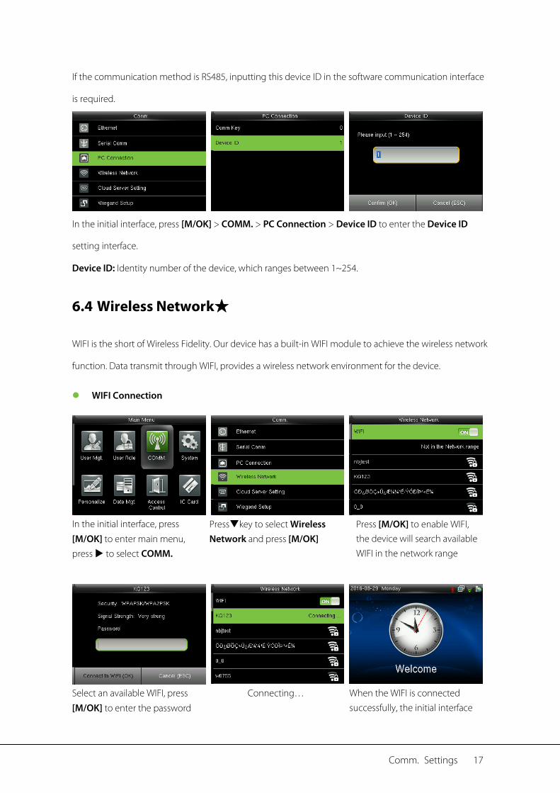
If the communication method is RS485, inputting this device ID in the software communication interface
is required.
In the initial interface, press [M/OK] > COMM. > PC Connection > Device ID to enter the Device ID
setting interface.
Device ID: Identity number of the device, which ranges between 1~254.
6.4 Wireless Network★
WIFI is the short of Wireless Fidelity. Our device has a built-in WIFI module to achieve the wireless network
function. Data transmit through WIFI, provides a wireless network environment for the device.
WIFI Connection
In the initial interface, press
[M/OK] to enter main menu, press to select COMM.
Presskey to select Wireless Network and press [M/OK]
Press [M/OK] to enable WIFI, the device will search available WIFI in the network range
Select an available WIFI, press [M/OK] to enter the password
Connecting… When the WIFI is connected successfully, the initial interface
18 User Manual for ProCapture-X
input interface. Input password
and press [M/OK] will display the logo.
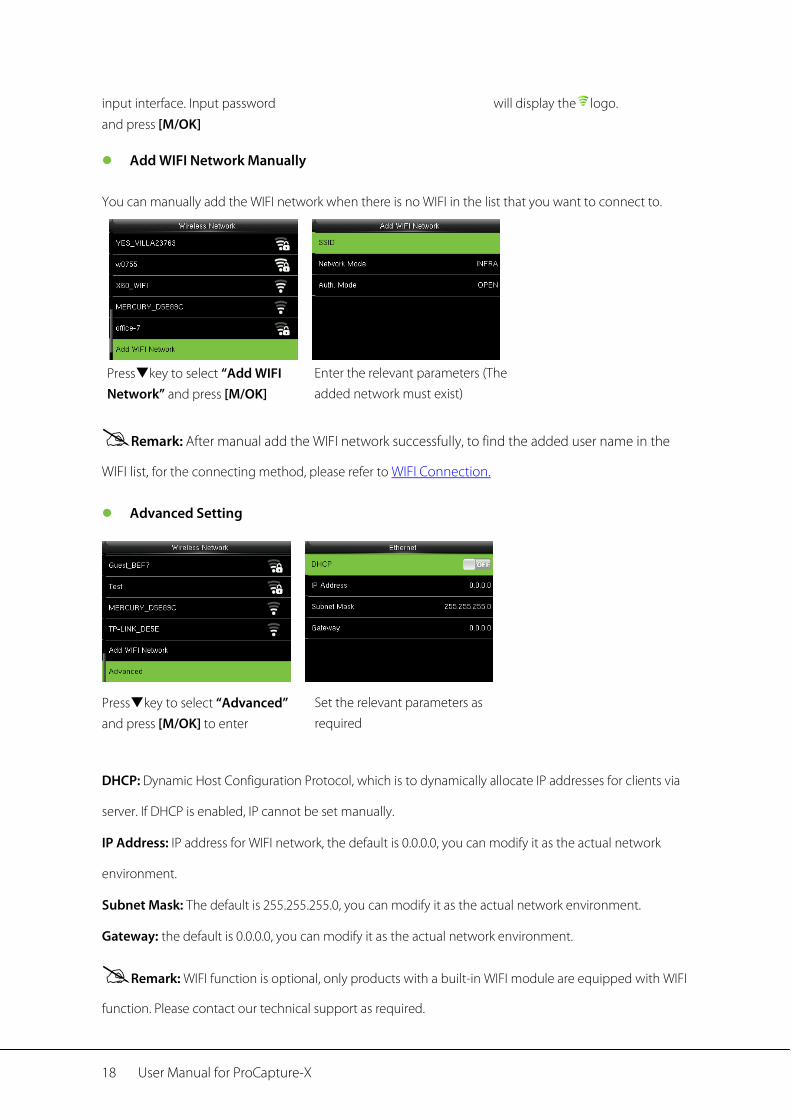
Add WIFI Network Manually
You can manually add the WIFI network when there is no WIFI in the list that you want to connect to.
Presskey to select “Add WIFI Network” and press [M/OK]
Enter the relevant parameters (The added network must exist)
Remark: After manual add the WIFI network successfully, to find the added user name in the
WIFI list, for the connecting method, please refer to WIFI Connection.
Advanced Setting
Presskey to select “Advanced” and press [M/OK] to enter
Set the relevant parameters as required
DHCP: Dynamic Host Configuration Protocol, which is to dynamically allocate IP addresses for clients via
server. If DHCP is enabled, IP cannot be set manually.
IP Address: IP address for WIFI network, the default is 0.0.0.0, you can modify it as the actual network
environment.
Subnet Mask: The default is 255.255.255.0, you can modify it as the actual network environment.
Gateway: the default is 0.0.0.0, you can modify it as the actual network environment.
Remark: WIFI function is optional, only products with a built-in WIFI module are equipped with WIFI
function. Please contact our technical support as required.
Comm. Settings 19
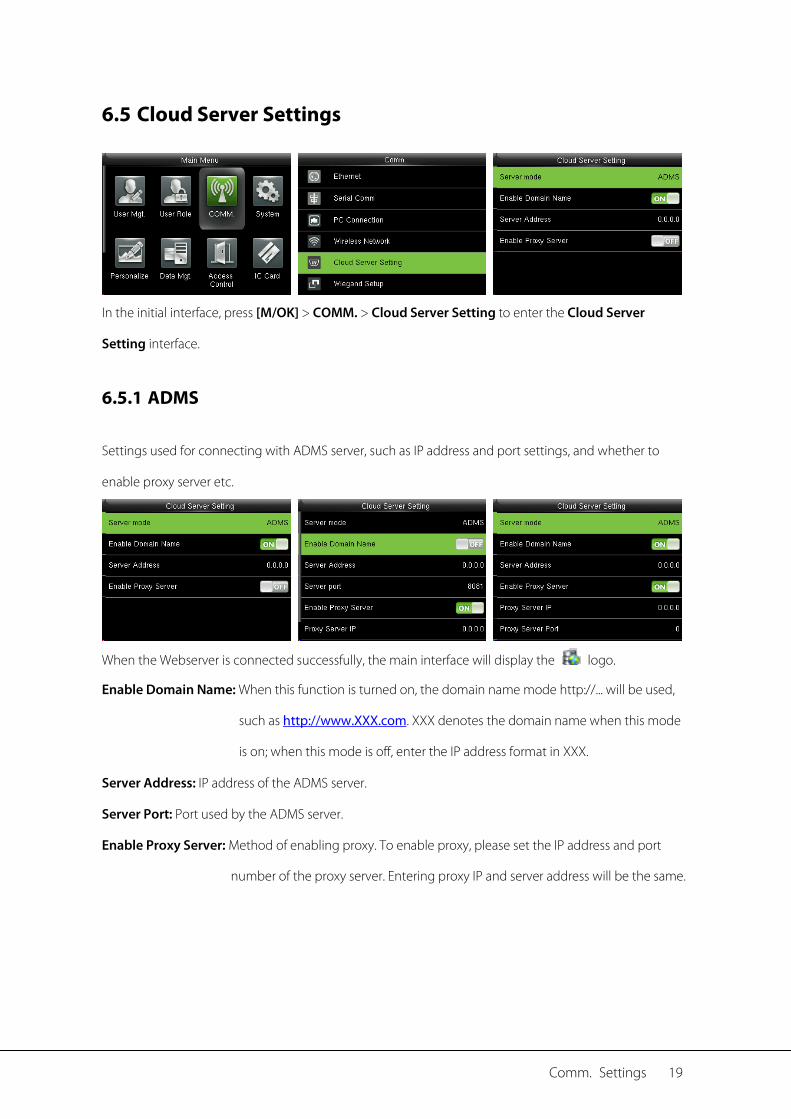
6.5 Cloud Server Settings
In the initial interface, press [M/OK] > COMM. > Cloud Server Setting to enter the Cloud Server
Setting interface.
6.5.1 ADMS
Settings used for connecting with ADMS server, such as IP address and port settings, and whether to
enable proxy server etc.
When the Webserver is connected successfully, the main interface will display the logo.
Enable Domain Name: When this function is turned on, the domain name mode http://... will be used,
such as http://www.XXX.com. XXX denotes the domain name when this mode
is on; when this mode is off, enter the IP address format in XXX.
Server Address: IP address of the ADMS server.
Server Port: Port used by the ADMS server.
Enable Proxy Server: Method of enabling proxy. To enable proxy, please set the IP address and port
number of the proxy server. Entering proxy IP and server address will be the same.
20 User Manual for ProCapture-X
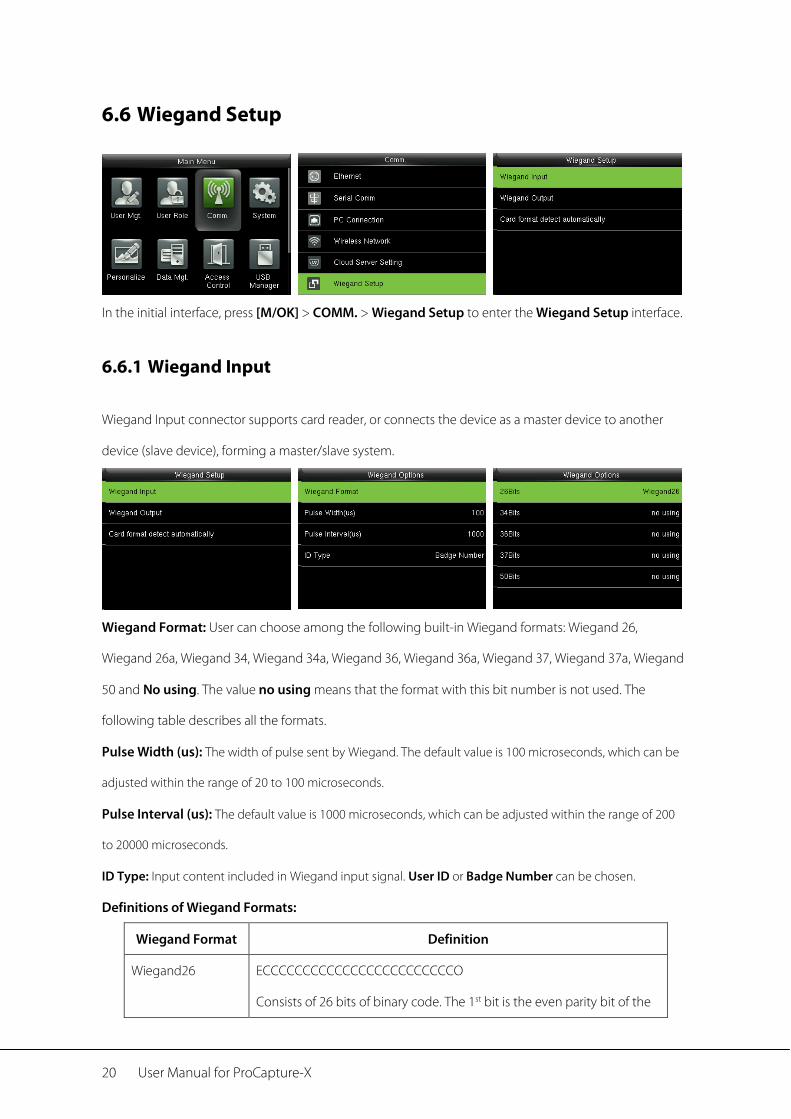
6.6 Wiegand Setup
In the initial interface, press [M/OK] > COMM. > Wiegand Setup to enter the Wiegand Setup interface.
6.6.1 Wiegand Input
Wiegand Input connector supports card reader, or connects the device as a master device to another
device (slave device), forming a master/slave system.
Wiegand Format: User can choose among the following built-in Wiegand formats: Wiegand 26,
Wiegand 26a, Wiegand 34, Wiegand 34a, Wiegand 36, Wiegand 36a, Wiegand 37, Wiegand 37a, Wiegand
50 and No using. The value no using means that the format with this bit number is not used. The
following table describes all the formats.
Pulse Width (us): The width of pulse sent by Wiegand. The default value is 100 microseconds, which can be
adjusted within the range of 20 to 100 microseconds.
Pulse Interval (us): The default value is 1000 microseconds, which can be adjusted within the range of 200
to 20000 microseconds.
ID Type: Input content included in Wiegand input signal. User ID or Badge Number can be chosen.
Definitions of Wiegand Formats:
Wiegand Format Definition
Wiegand26 ECCCCCCCCCCCCCCCCCCCCCCCCO
Consists of 26 bits of binary code. The 1st bit is the even parity bit of the

Comm. Settings 21
2nd to 13th bits, while the 26th bit is the odd parity bit of the 14th to 25th
bits. The 2nd to 25th bits are the card number.
Wiegand26a ESSSSSSSSCCCCCCCCCCCCCCCCO
Consists of 26 bits of binary code. The 1st bit is the even parity bit of the
2nd to 13th bits, while the 26th bit is the odd parity bit of the 14th to 25th
bits. The 2nd to 9th bits are the site code, while the 10th to 25th bits are the
card number.
Wiegand34 ECCCCCCCCCCCCCCCCCCCCCCCCCCCCCCCCO
Consists of 34 bits of binary code. The 1st bit is the even parity bit of the
2nd to 17th bits, while the 34th bit is the odd parity bit of the 18th to 33rd
bits. The 2nd to 25th bits are the card number.
Wiegand34a ESSSSSSSSCCCCCCCCCCCCCCCCCCCCCCCCO
Consists of 34 bits of binary code. The 1st bit is the even parity bit of the
2nd to 17th bits, while the 34th bit is the odd parity bit of the 18th to 33rd
bits. The 2nd to 9th bits are the site code, while the 10th to 25th bits are the
card number.
Wiegand36 OFFFFFFFFFFFFFFFFCCCCCCCCCCCCCCCCMME
Consists of 36 bits of binary code. The 1st bit is the odd parity bit of the
2nd to 18th bits, while the 36th bit is the even parity bit of the 19th to 35th
bits. The 2nd to 17th bits are the device code, the 18th to 33rd bits are the
card number, and the 34th to 35th bits are the manufacturer code.
Wiegand36a EFFFFFFFFFFFFFFFFFFCCCCCCCCCCCCCCCCO
Consists of 36 bits of binary code. The 1st bit is the even parity bit of the
2nd to 18th bits, while the 36th bit is the odd parity bit of the 19th to 35th
bits. The 2nd to 19th bits are the device code, and the 20th to 35th bits are
the card number.
Wiegand37 OMMMMSSSSSSSSSSSSCCCCCCCCCCCCCCCCCCCE
Consists of 37 bits of binary code. The 1st bit is the odd parity bit of the
2nd to 18th bits, while the 37th bit is the even parity bit of the 19th to 36th
22 User Manual for ProCapture-X
bits. The 2nd to 4th bits are the manufacturer code, the 5th to 16th bits are
the site code, and the 21st to 36th bits are the card number.
Wiegand37a EMMMFFFFFFFFFFSSSSSSCCCCCCCCCCCCCCCCO
Consists of 37 bits of binary code. The 1st bit is the even parity bit of the
2nd to 18th bits, while the 37th bit is the odd parity bit of the 19th to 35th
bits. The 2nd to 4th bits are the manufacturer code, 5th to 14th bits are the
device code, 15th to 20th bits are the site code, and the 21st to 36th bits
are the card number.
Wiegand50 ESSSSSSSSSSSSSSSSCCCCCCCCCCCCCCCCCCCCCCCCCCCCCCCCO
Consists of 50 bits of binary code. The 1st bit is the even parity bit of the
2nd to 25th bits, while the 50th bit is the odd parity bit of the 26th to 49th
bits. The 2nd to 17th bits are the site code, and 18th to 49th bits are the
card number.
Note: C denotes card number, E denotes even parity bit, O denotes odd parity bit, F denotes device
code, M denotes manufacturer code, P denotes parity bit, and S denotes site code.
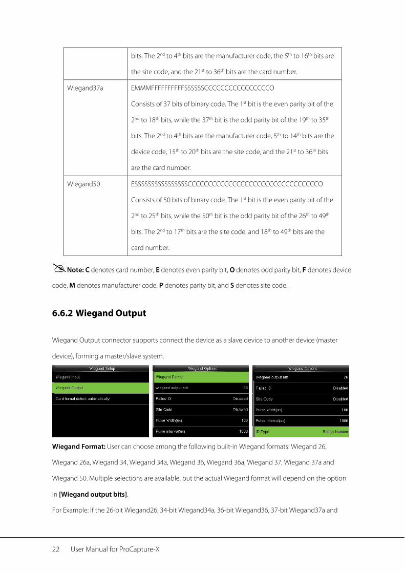
6.6.2 Wiegand Output
Wiegand Output connector supports connect the device as a slave device to another device (master
device), forming a master/slave system.
Wiegand Format: User can choose among the following built-in Wiegand formats: Wiegand 26,
Wiegand 26a, Wiegand 34, Wiegand 34a, Wiegand 36, Wiegand 36a, Wiegand 37, Wiegand 37a and
Wiegand 50. Multiple selections are available, but the actual Wiegand format will depend on the option
in [Wiegand output bits].
For Example: If the 26-bit Wiegand26, 34-bit Wiegand34a, 36-bit Wiegand36, 37-bit Wiegand37a and
Comm. Settings 23
50-bit Wiegand50 are chosen in [Wiegand Format], but 36 bits is selected in [Wiegand output bits],
then the actual Wiegand format for use will be 36-bit Wiegand36.
Wiegand output bits: Number of bits of Wiegand data. After choosing [Wiegand output bits], the
device will use the set number of bits to find the suitable Wiegand format in [Wiegand Format].
Failed ID: It is defined as the output value of failed user verification. The output format depends on the
[Wiegand Format] setting. The default value ranges from 0 to 65535.
Site Code: It is similar to device ID except that it can be set manually and repeatable with different
devices. The default value ranges from 0 to 256.
Pulse Width (us): The width of pulse sent by Wiegand. The default value is 100 microseconds, which can be
adjusted within the range of 20 to 100 microseconds.
Pulse Interval (us): The default value is 1000 microseconds, which can be adjusted within the range of 200
to 20000 microseconds.
ID Type: Output content after successful verification. User ID or card number can be chosen.
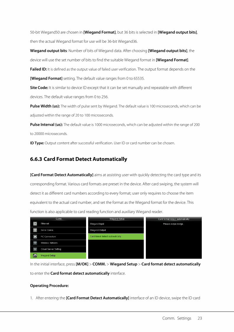
6.6.3 Card Format Detect Automatically
[Card Format Detect Automatically] aims at assisting user with quickly detecting the card type and its
corresponding format. Various card formats are preset in the device. After card swiping, the system will
detect it as different card numbers according to every format; user only requires to choose the item
equivalent to the actual card number, and set the format as the Wiegand format for the device. This
function is also applicable to card reading function and auxiliary Wiegand reader.
In the initial interface, press [M/OK] > COMM. > Wiegand Setup > Card format detect automatically
to enter the Card format detect automatically interface.
Operating Procedure:
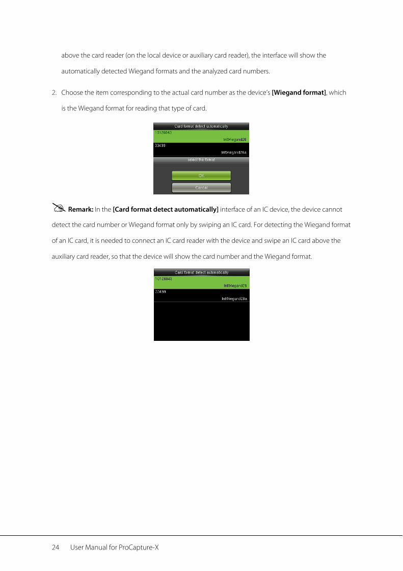
1. After entering the [Card Format Detect Automatically] interface of an ID device, swipe the ID card
24 User Manual for ProCapture-X
above the card reader (on the local device or auxiliary card reader), the interface will show the
automatically detected Wiegand formats and the analyzed card numbers.
2. Choose the item corresponding to the actual card number as the device’s [Wiegand format], which
is the Wiegand format for reading that type of card.
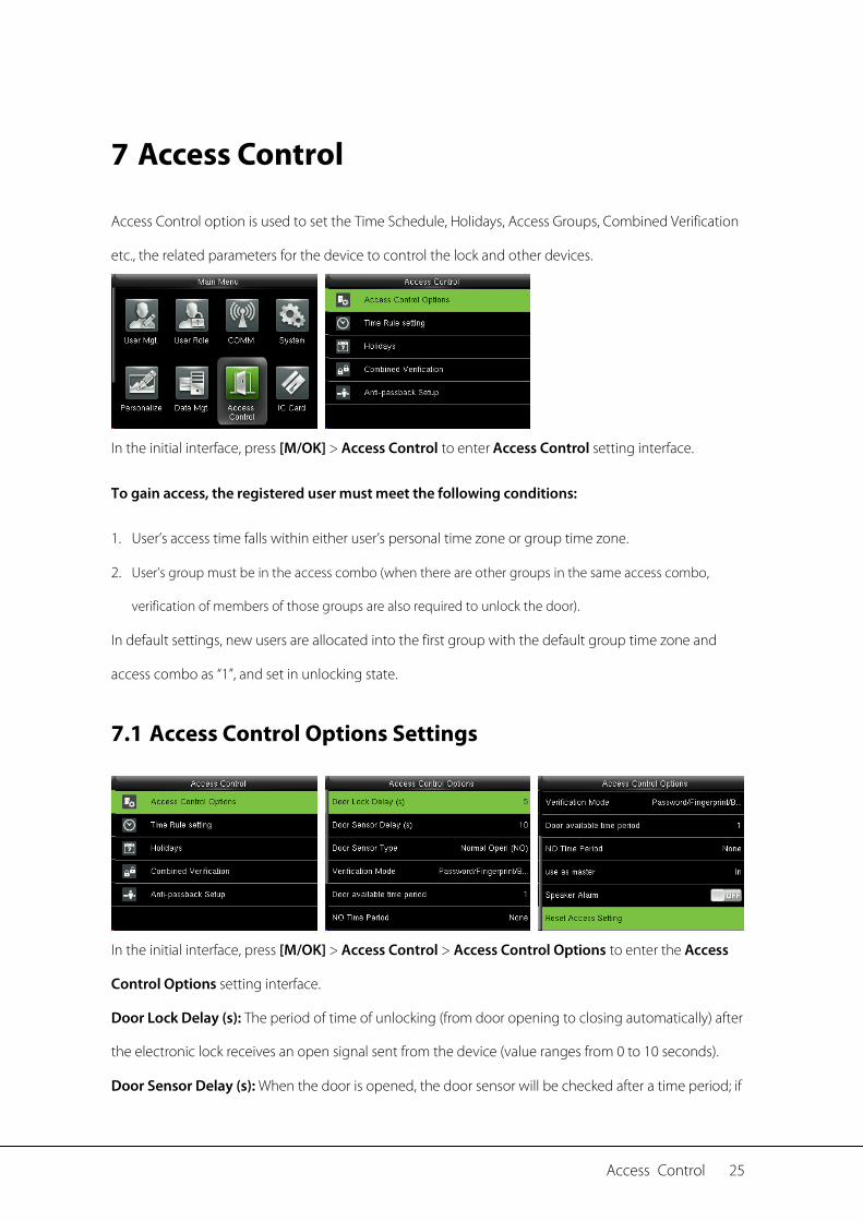
Remark: In the [Card format detect automatically] interface of an IC device, the device cannot
detect the card number or Wiegand format only by swiping an IC card. For detecting the Wiegand format
of an IC card, it is needed to connect an IC card reader with the device and swipe an IC card above the
auxiliary card reader, so that the device will show the card number and the Wiegand format.
Access Control 25
7 Access Control
Access Control option is used to set the Time Schedule, Holidays, Access Groups, Combined Verification
etc., the related parameters for the device to control the lock and other devices.
In the initial interface, press [M/OK] > Access Control to enter Access Control setting interface.
To gain access, the registered user must meet the following conditions:
1. User’s access time falls within either user’s personal time zone or group time zone.
2. User’s group must be in the access combo (when there are other groups in the same access combo,
verification of members of those groups are also required to unlock the door).
In default settings, new users are allocated into the first group with the default group time zone and
access combo as “1”, and set in unlocking state.
7.1 Access Control Options Settings
In the initial interface, press [M/OK] > Access Control > Access Control Options to enter the Access
Control Options setting interface.
Door Lock Delay (s): The period of time of unlocking (from door opening to closing automatically) after
the electronic lock receives an open signal sent from the device (value ranges from 0 to 10 seconds).
Door Sensor Delay (s): When the door is opened, the door sensor will be checked after a time period; if

26 User Manual for ProCapture-X
the state of the door sensor is inconsistent with that of the door sensor mode, alarm will be triggered.
The time period is the Door Sensor Delay (value ranges from 1 to 255 seconds).
Door Sensor Type: It includes None, Normal Open (NO) and Normal Close (NC). None means door
sensor is not in use; Normal Open means the door is opened when electricity is on; Normal Close
means the door is closed when electricity is on.
Verification Mode: Select verification mode to open door, including password / fingerprint / badge,
fingerprint only, user ID only, password, badge only, fingerprint / password, fingerprint / badge, password
/ badge, user ID + fingerprint, fingerprint + password, fingerprint + badge, fingerprint + password +
badge, password + badge, user ID + fingerprint + password, fingerprint + badge + user ID.
Remarks:
1. “/” means “or”. “+” means “and”.
2. In a combined verification mode, the corresponding verification information must be registered
first. For example: When User A registers fingerprint only, and the [Verification Mode] is set as
“Password + Badge”, User A will not pass verification.
Door available time period: Set periods to open the door for users.
NO Time Period: To set time period for Normally Open, so that the door is always unlocked during this
period.
Use as master: While configuring the master and slave devices, you may set the state of the master as
Out or In.
Out: A record of verification on the master device is a check-out record.
In: A record of verification on the master device is a check-in record.
Speaker Alarm: When the [Speaker Alarm] is enabled, the speaker will raise an alarm when the device
is being dismantled.
Access Control 27
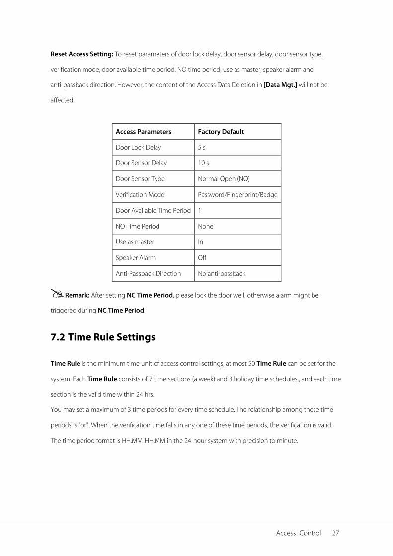
Reset Access Setting: To reset parameters of door lock delay, door sensor delay, door sensor type,
verification mode, door available time period, NO time period, use as master, speaker alarm and
anti-passback direction. However, the content of the Access Data Deletion in [Data Mgt.] will not be
affected.
Access Parameters Factory Default
Door Lock Delay 5 s
Door Sensor Delay 10 s
Door Sensor Type Normal Open (NO)
Verification Mode Password/Fingerprint/Badge
Door Available Time Period 1
NO Time Period None
Use as master In
Speaker Alarm Off
Anti-Passback Direction No anti-passback
Remark: After setting NC Time Period, please lock the door well, otherwise alarm might be
triggered during NC Time Period.
7.2 Time Rule Settings
Time Rule is the minimum time unit of access control settings; at most 50 Time Rule can be set for the
system. Each Time Rule consists of 7 time sections (a week) and 3 holiday time schedules,, and each time
section is the valid time within 24 hrs.
You may set a maximum of 3 time periods for every time schedule. The relationship among these time
periods is "or". When the verification time falls in any one of these time periods, the verification is valid.
The time period format is HH:MM-HH:MM in the 24-hour system with precision to minute.

28 User Manual for ProCapture-X
In the initial interface, press [M/OK] > Access Control > Time Rule Setting to enter the Time Rule
Setting interface. The default Time Rule No. is 1 (whole-day valid), which can be edited.
Access Control 29
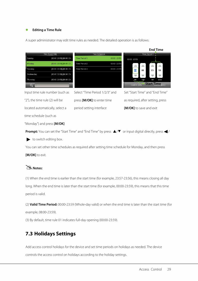
Editing a Time Rule
A super administrator may edit time rules as needed. The detailed operation is as follows:
Input time rule number (such as
“2”), the time rule (2) will be
located automatically, select a
time schedule (such as
“Monday”) and press [M/OK]
Select “Time Period 1/2/3” and
press [M/OK] to enter time
period setting interface
Set “Start Time” and “End Time”
as required, after setting, press
[M/OK] to save and exit
Prompt: You can set the “Start Time” and “End Time” by press ▲/▼ or input digital directly, press /
to switch editing box.
You can set other time schedules as required after setting time schedule for Monday, and then press
[M/OK] to exit.
Notes:
(1) When the end time is earlier than the start time (for example, 23:57-23:56), this means closing all day
long. When the end time is later than the start time (for example, 00:00-23:59), this means that this time
period is valid.
(2) Valid Time Period: 00:00-23:59 (Whole-day valid) or when the end time is later than the start time (for
example, 08:00-23:59).
(3) By default, time rule 01 indicates full-day opening (00:00-23:59).
7.3 Holidays Settings
Add access control holidays for the device and set time periods on holidays as needed. The device
controls the access control on holidays according to the holiday settings.
End Time
Start Time
30 User Manual for ProCapture-X
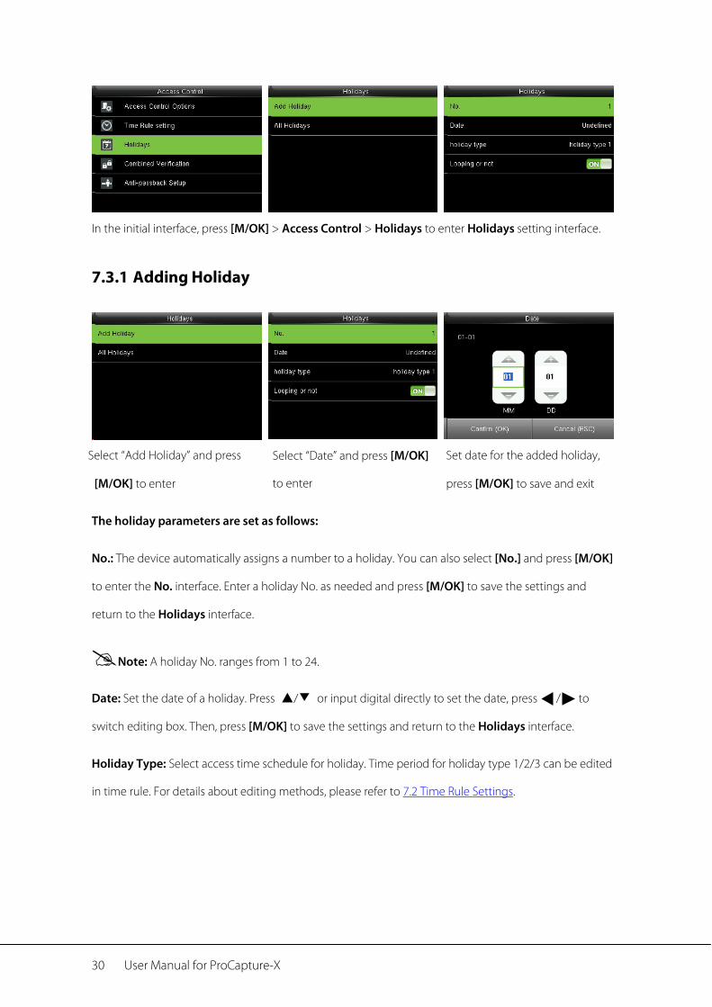
In the initial interface, press [M/OK] > Access Control > Holidays to enter Holidays setting interface.
7.3.1 Adding Holiday
Select “Add Holiday” and press
[M/OK] to enter
Select “Date” and press [M/OK]
to enter
Set date for the added holiday,
press [M/OK] to save and exit
The holiday parameters are set as follows:
No.: The device automatically assigns a number to a holiday. You can also select [No.] and press [M/OK]
to enter the No. interface. Enter a holiday No. as needed and press [M/OK] to save the settings and
return to the Holidays interface.
Note: A holiday No. ranges from 1 to 24.
Date: Set the date of a holiday. Press ▲/▼ or input digital directly to set the date, press / to
switch editing box. Then, press [M/OK] to save the settings and return to the Holidays interface.
Holiday Type: Select access time schedule for holiday. Time period for holiday type 1/2/3 can be edited
in time rule. For details about editing methods, please refer to 7.2 Time Rule Settings.
Access Control 31
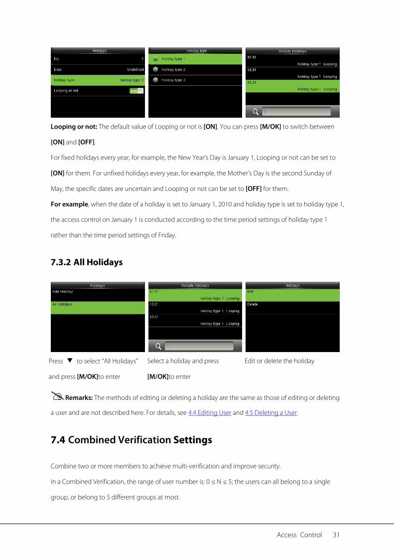
Looping or not: The default value of Looping or not is [ON]. You can press [M/OK] to switch between
[ON] and [OFF].
For fixed holidays every year, for example, the New Year's Day is January 1, Looping or not can be set to
[ON] for them. For unfixed holidays every year, for example, the Mother's Day is the second Sunday of
May, the specific dates are uncertain and Looping or not can be set to [OFF] for them.
For example, when the date of a holiday is set to January 1, 2010 and holiday type is set to holiday type 1,
the access control on January 1 is conducted according to the time period settings of holiday type 1
rather than the time period settings of Friday.
7.3.2 All Holidays
Press ▼ to select “All Holidays”
and press [M/OK]to enter
Select a holiday and press
[M/OK]to enter
Edit or delete the holiday
Remarks: The methods of editing or deleting a holiday are the same as those of editing or deleting
a user and are not described here. For details, see 4.4 Editing User and 4.5 Deleting a User.
7.4 Combined Verification Settings
Combine two or more members to achieve multi-verification and improve security.
In a Combined Verification, the range of user number is: 0 ≤ N ≤ 5; the users can all belong to a single
group, or belong to 5 different groups at most.
32 User Manual for ProCapture-X
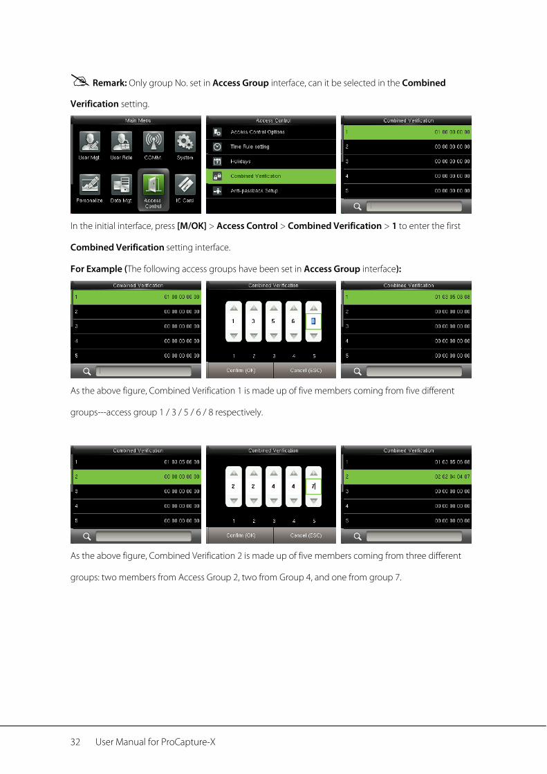
Remark: Only group No. set in Access Group interface, can it be selected in the Combined
Verification setting.
In the initial interface, press [M/OK] > Access Control > Combined Verification > 1 to enter the first
Combined Verification setting interface.
For Example (The following access groups have been set in Access Group interface):
As the above figure, Combined Verification 1 is made up of five members coming from five different
groups---access group 1 / 3 / 5 / 6 / 8 respectively.
As the above figure, Combined Verification 2 is made up of five members coming from three different
groups: two members from Access Group 2, two from Group 4, and one from group 7.
Access Control 33
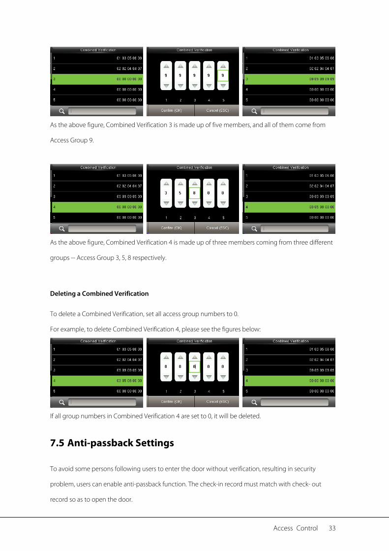
As the above figure, Combined Verification 3 is made up of five members, and all of them come from
Access Group 9.
As the above figure, Combined Verification 4 is made up of three members coming from three different
groups -- Access Group 3, 5, 8 respectively.
Deleting a Combined Verification
To delete a Combined Verification, set all access group numbers to 0.
For example, to delete Combined Verification 4, please see the figures below:
If all group numbers in Combined Verification 4 are set to 0, it will be deleted.
7.5 Anti-passback Settings
To avoid some persons following users to enter the door without verification, resulting in security
problem, users can enable anti-passback function. The check-in record must match with check- out
record so as to open the door.
34 User Manual for ProCapture-X
This function requires two devices to work together: one is installed inside the door (master device), the
other one is installed outside the door (slave device). The two devices communicate via Wiegand signal.
The Wiegand format and Output type (User ID / Badge Number) adopted by the master device and slave
device must be consistent.
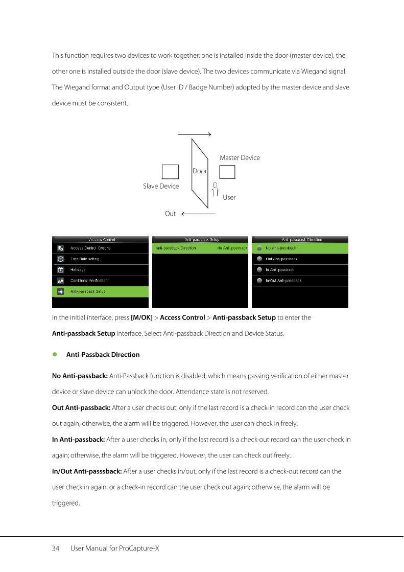
In the initial interface, press [M/OK] > Access Control > Anti-passback Setup to enter the
Anti-passback Setup interface. Select Anti-passback Direction and Device Status.
Anti-Passback Direction
No Anti-passback: Anti-Passback function is disabled, which means passing verification of either master
device or slave device can unlock the door. Attendance state is not reserved.
Out Anti-passback: After a user checks out, only if the last record is a check-in record can the user check
out again; otherwise, the alarm will be triggered. However, the user can check in freely.
In Anti-passback: After a user checks in, only if the last record is a check-out record can the user check in
again; otherwise, the alarm will be triggered. However, the user can check out freely.
In/Out Anti-passsback: After a user checks in/out, only if the last record is a check-out record can the
user check in again, or a check-in record can the user check out again; otherwise, the alarm will be
triggered.
Out
Master Device
Slave Device
User
Door
System Settings 35
8 System Settings
8.1 Access Logs Settings
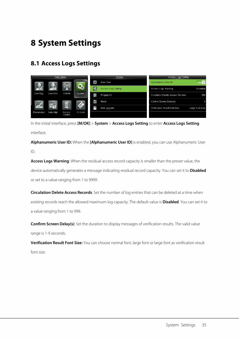
In the initial interface, press [M/OK] > System > Access Logs Setting to enter Access Logs Setting
interface.
Alphanumeric User ID: When the [Alphanumeric User ID] is enabled, you can use Alphanumeric User
ID.
Access Logs Warning: When the residual access record capacity is smaller than the preset value, the
device automatically generates a message indicating residual record capacity. You can set it to Disabled
or set to a value ranging from 1 to 9999.
Circulation Delete Access Records: Set the number of log entries that can be deleted at a time when
existing records reach the allowed maximum log capacity. The default value is Disabled. You can set it to
a value ranging from 1 to 999.
Confirm Screen Delay(s): Set the duration to display messages of verification results. The valid value
range is 1-9 seconds.
Verification Result Font Size: You can choose normal font, large font or large font as verification result
font size.
36 User Manual for ProCapture-X
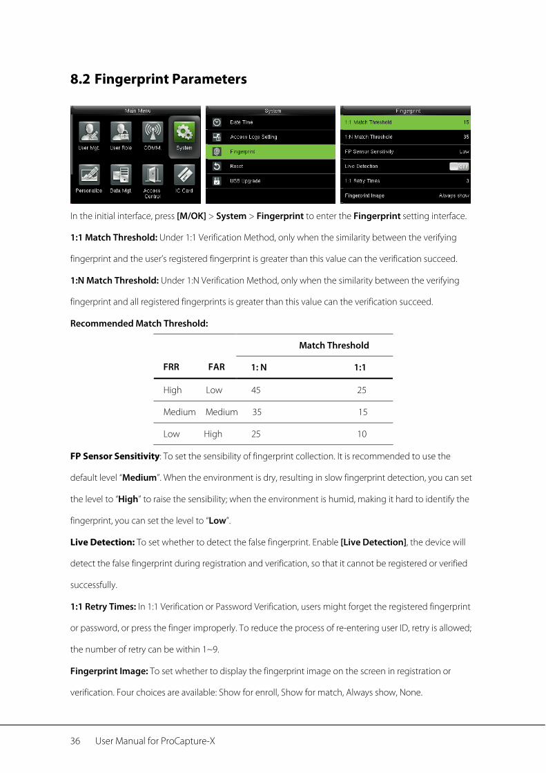
8.2 Fingerprint Parameters
In the initial interface, press [M/OK] > System > Fingerprint to enter the Fingerprint setting interface.
1:1 Match Threshold: Under 1:1 Verification Method, only when the similarity between the verifying
fingerprint and the user’s registered fingerprint is greater than this value can the verification succeed.
1:N Match Threshold: Under 1:N Verification Method, only when the similarity between the verifying
fingerprint and all registered fingerprints is greater than this value can the verification succeed.
Recommended Match Threshold:
FRR FAR
Match Threshold
1: N 1:1
High Low 45 25
Medium Medium 35 15
Low High 25 10
FP Sensor Sensitivity: To set the sensibility of fingerprint collection. It is recommended to use the
default level “Medium”. When the environment is dry, resulting in slow fingerprint detection, you can set
the level to “High” to raise the sensibility; when the environment is humid, making it hard to identify the
fingerprint, you can set the level to “Low”.
Live Detection: To set whether to detect the false fingerprint. Enable [Live Detection], the device will
detect the false fingerprint during registration and verification, so that it cannot be registered or verified
successfully.
1:1 Retry Times: In 1:1 Verification or Password Verification, users might forget the registered fingerprint
or password, or press the finger improperly. To reduce the process of re-entering user ID, retry is allowed;
the number of retry can be within 1~9.
Fingerprint Image: To set whether to display the fingerprint image on the screen in registration or
verification. Four choices are available: Show for enroll, Show for match, Always show, None.
System Settings 37
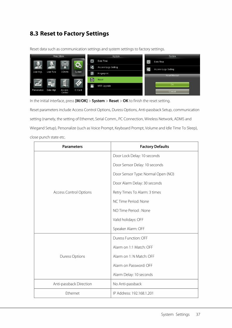
8.3 Reset to Factory Settings
Reset data such as communication settings and system settings to factory settings.
In the initial interface, press [M/OK] > System > Reset > OK to finish the reset setting.
Reset parameters include Access Control Options, Duress Options, Anti-passback Setup, communication
setting (namely, the setting of Ethernet, Serial Comm., PC Connection, Wireless Network, ADMS and
Wiegand Setup), Personalize (such as Voice Prompt, Keyboard Prompt, Volume and Idle Time To Sleep),
close punch state etc.
Parameters Factory Defaults
Access Control Options
Door Lock Delay: 10 seconds
Door Sensor Delay: 10 seconds
Door Sensor Type: Normal Open (NO)
Door Alarm Delay: 30 seconds
Retry Times To Alarm: 3 times
NC Time Period: None
NO Time Period : None
Valid holidays: OFF
Speaker Alarm: OFF
Duress Options
Duress Function: OFF
Alarm on 1:1 Match: OFF
Alarm on 1: N Match: OFF
Alarm on Password: OFF
Alarm Delay: 10 seconds
Anti-passback Direction No Anti-passback
Ethernet IP Address: 192.168.1.201
38 User Manual for ProCapture-X
Subnet Mask: 255.255.255.0
DNS: 0.0.0.0
PC Connection Comm Key: 0
Device ID: 1
ADMS
Enable Domain Name: OFF
Server Address: 0.0.0.0
Server Port: 8081
Enable Proxy Server: OFF
Wiegand Setup
Wiegand Input / Output ID Type: Badge Number
Pulse Width: 100 us
Pulse interval: 1000 us
Idle Time To Slide Show 60 seconds
Idle Time To Sleep 30 minutes
Menu Screen Timeout 60 seconds
Keyboard Prompt ON
Voice Prompt ON
Volune 70
Remark: When resetting to factory settings, the date and time will not be affected. For example, if
the device date and time are set to 18:30 on January 1, 2020, the date and time will remain unchanged
after resetting to factory settings.
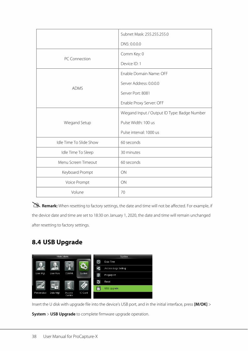
8.4 USB Upgrade
Insert the U disk with upgrade file into the device’s USB port, and in the initial interface, press [M/OK] >
System > USB Upgrade to complete firmware upgrade operation.

System Settings 39
If upgrade file is needed, please contact out technical support.
Firmware upgrade is not recommenced under normal circumstances.
40 User Manual for ProCapture-X
9 Personalize Settings
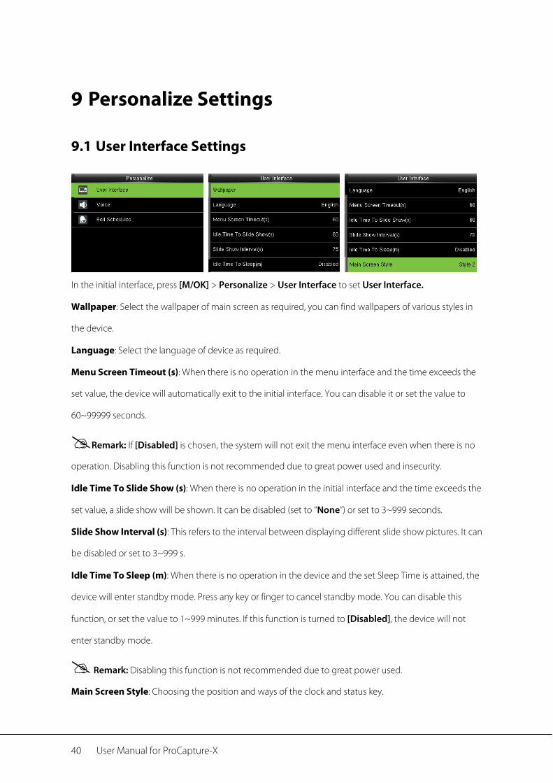
9.1 User Interface Settings
In the initial interface, press [M/OK] > Personalize > User Interface to set User Interface.
Wallpaper: Select the wallpaper of main screen as required, you can find wallpapers of various styles in
the device.
Language: Select the language of device as required.
Menu Screen Timeout (s): When there is no operation in the menu interface and the time exceeds the
set value, the device will automatically exit to the initial interface. You can disable it or set the value to
60~99999 seconds.
Remark: If [Disabled] is chosen, the system will not exit the menu interface even when there is no
operation. Disabling this function is not recommended due to great power used and insecurity. Idle Time To Slide Show (s): When there is no operation in the initial interface and the time exceeds the
set value, a slide show will be shown. It can be disabled (set to “None”) or set to 3~999 seconds.
Slide Show Interval (s): This refers to the interval between displaying different slide show pictures. It can
be disabled or set to 3~999 s.
Idle Time To Sleep (m): When there is no operation in the device and the set Sleep Time is attained, the
device will enter standby mode. Press any key or finger to cancel standby mode. You can disable this
function, or set the value to 1~999 minutes. If this function is turned to [Disabled], the device will not
enter standby mode.
Remark: Disabling this function is not recommended due to great power used.
Main Screen Style: Choosing the position and ways of the clock and status key.
Personalize Settings 41
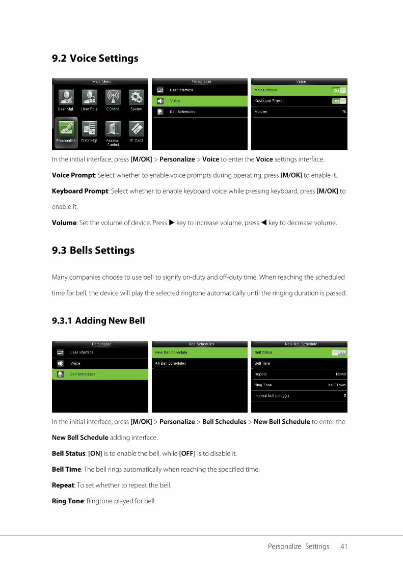
9.2 Voice Settings
In the initial interface, press [M/OK] > Personalize > Voice to enter the Voice settings interface.
Voice Prompt: Select whether to enable voice prompts during operating, press [M/OK] to enable it.
Keyboard Prompt: Select whether to enable keyboard voice while pressing keyboard, press [M/OK] to
enable it.
Volume: Set the volume of device. Press key to increase volume, press key to decrease volume.
9.3 Bells Settings
Many companies choose to use bell to signify on-duty and off-duty time. When reaching the scheduled
time for bell, the device will play the selected ringtone automatically until the ringing duration is passed.
9.3.1 Adding New Bell
In the initial interface, press [M/OK] > Personalize > Bell Schedules > New Bell Schedule to enter the
New Bell Schedule adding interface.
Bell Status: [ON] is to enable the bell, while [OFF] is to disable it.
Bell Time: The bell rings automatically when reaching the specified time.
Repeat: To set whether to repeat the bell.
Ring Tone: Ringtone played for bell.
42 User Manual for ProCapture-X
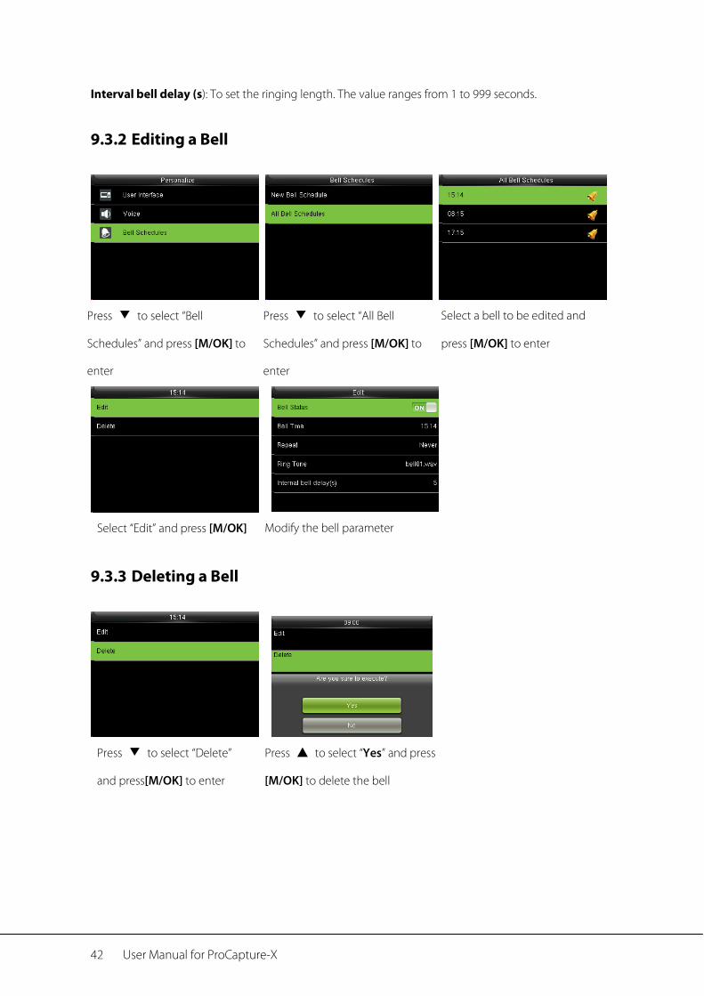
Interval bell delay (s): To set the ringing length. The value ranges from 1 to 999 seconds.
9.3.2 Editing a Bell
Press ▼ to select “Bell
Schedules” and press [M/OK] to
enter
Press ▼ to select “All Bell
Schedules” and press [M/OK] to
enter
Select a bell to be edited and
press [M/OK] to enter
Select “Edit” and press [M/OK] Modify the bell parameter
9.3.3 Deleting a Bell
Press ▼ to select “Delete”
and press[M/OK] to enter
Press ▲ to select “Yes” and press
[M/OK] to delete the bell
Data Mgt. 43
10 Data Mgt.
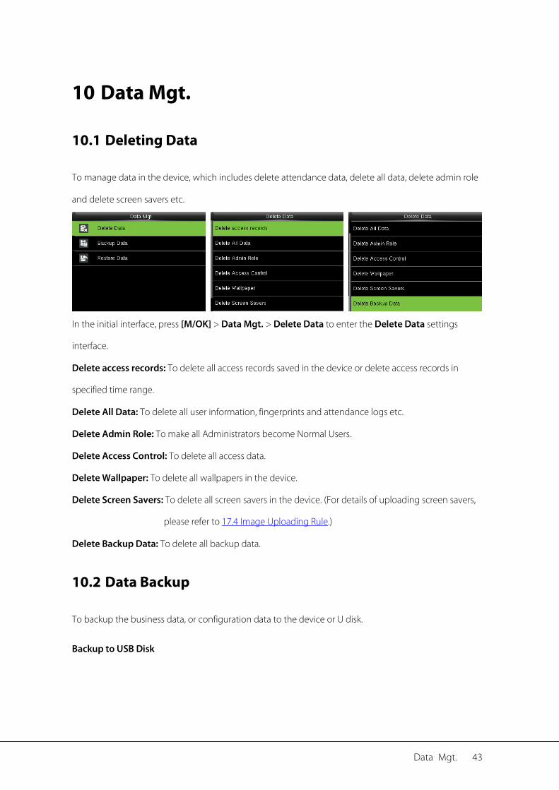
10.1 Deleting Data
To manage data in the device, which includes delete attendance data, delete all data, delete admin role
and delete screen savers etc.
In the initial interface, press [M/OK] > Data Mgt. > Delete Data to enter the Delete Data settings
interface.
Delete access records: To delete all access records saved in the device or delete access records in
specified time range.
Delete All Data: To delete all user information, fingerprints and attendance logs etc.
Delete Admin Role: To make all Administrators become Normal Users.
Delete Access Control: To delete all access data.
Delete Wallpaper: To delete all wallpapers in the device.
Delete Screen Savers: To delete all screen savers in the device. (For details of uploading screen savers,
please refer to 17.4 Image Uploading Rule.)
Delete Backup Data: To delete all backup data.
10.2 Data Backup
To backup the business data, or configuration data to the device or U disk.
Backup to USB Disk
44 User Manual for ProCapture-X
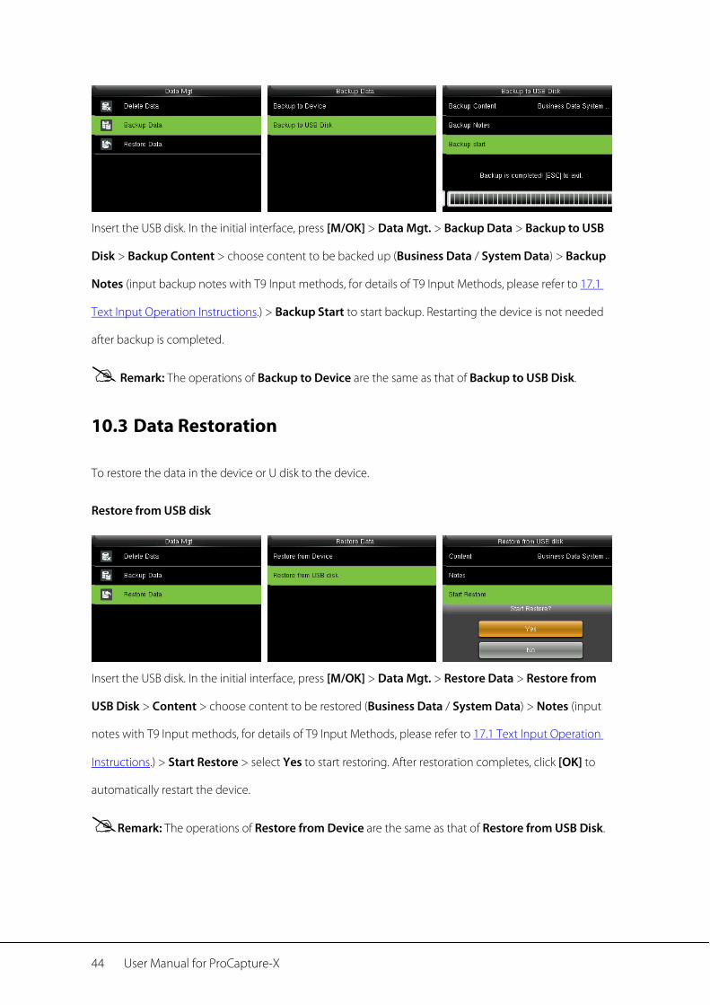
Insert the USB disk. In the initial interface, press [M/OK] > Data Mgt. > Backup Data > Backup to USB
Disk > Backup Content > choose content to be backed up (Business Data / System Data) > Backup
Notes (input backup notes with T9 Input methods, for details of T9 Input Methods, please refer to 17.1
Text Input Operation Instructions.) > Backup Start to start backup. Restarting the device is not needed
after backup is completed.
Remark: The operations of Backup to Device are the same as that of Backup to USB Disk.
10.3 Data Restoration
To restore the data in the device or U disk to the device.
Restore from USB disk
Insert the USB disk. In the initial interface, press [M/OK] > Data Mgt. > Restore Data > Restore from
USB Disk > Content > choose content to be restored (Business Data / System Data) > Notes (input
notes with T9 Input methods, for details of T9 Input Methods, please refer to 17.1 Text Input Operation
Instructions.) > Start Restore > select Yes to start restoring. After restoration completes, click [OK] to
automatically restart the device.
Remark: The operations of Restore from Device are the same as that of Restore from USB Disk.
IC Card★ 45
11 IC Card★
To enroll a Mifare card as ID card or fingerprint card. This menu supports integrate fingerprint and ID card
attendance to other systems or devices by the enrolled Mifare card, and supports multi- verification
mode to meet the demands of different people. It also supports clean, copy card data enrolled in the
Mifare card.
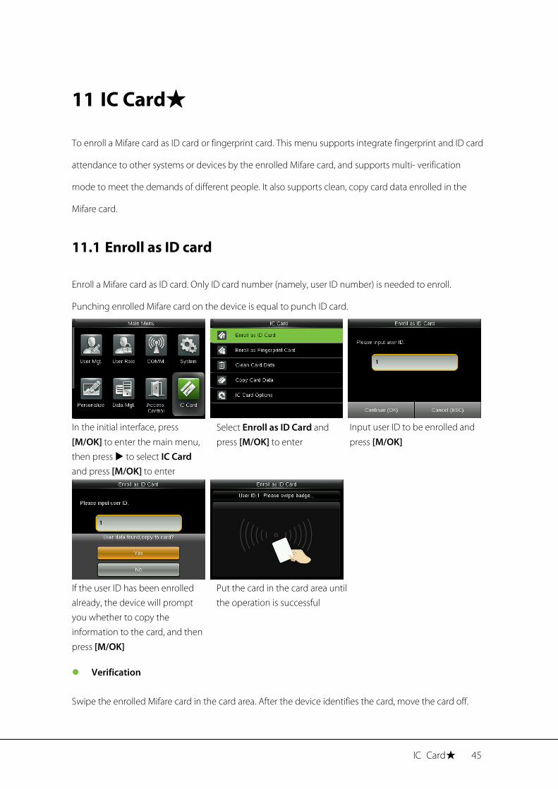
11.1 Enroll as ID card
Enroll a Mifare card as ID card. Only ID card number (namely, user ID number) is needed to enroll.
Punching enrolled Mifare card on the device is equal to punch ID card.
In the initial interface, press
[M/OK] to enter the main menu, then press to select IC Card and press [M/OK] to enter
Select Enroll as ID Card and press [M/OK] to enter
Input user ID to be enrolled and
press [M/OK]
If the user ID has been enrolled already, the device will prompt you whether to copy the information to the card, and then
press [M/OK]
Put the card in the card area until the operation is successful
Verification
Swipe the enrolled Mifare card in the card area. After the device identifies the card, move the card off.
46 User Manual for ProCapture-X
When the verification is successful, the device will prompt the card number.
Remark: Please modify the verification mode as badge related modes in user access control role (In
the initial interface, press [M/OK] > User Mgt. > All Users > select a user > press [M/OK] > Edit >
Access Control Role > Verification Mode), or the verification won’t be successful.
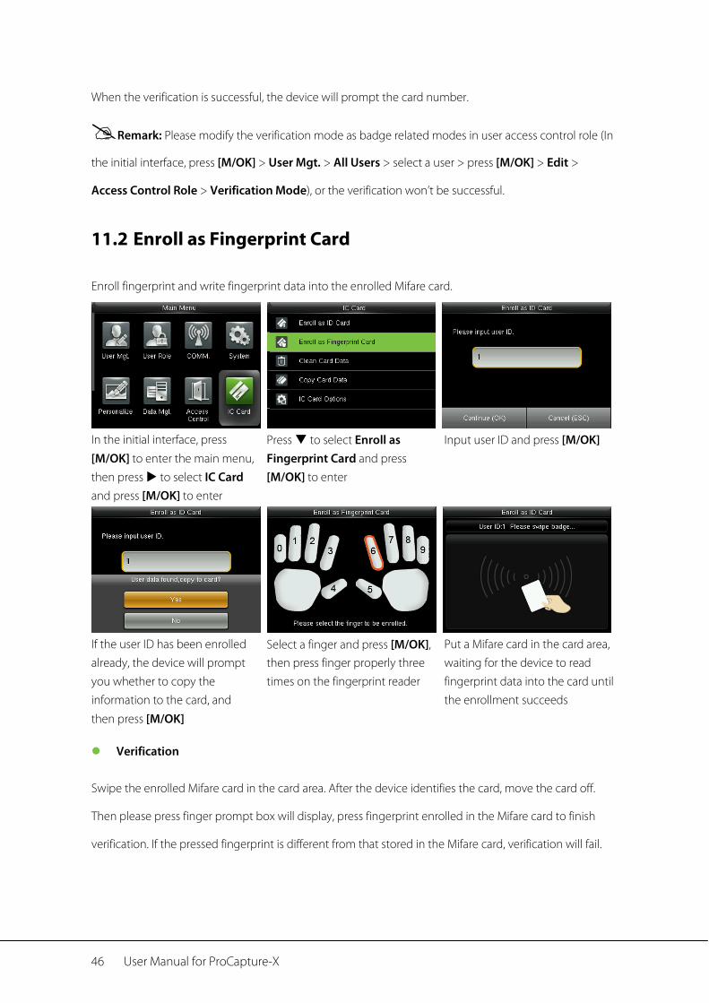
11.2 Enroll as Fingerprint Card
Enroll fingerprint and write fingerprint data into the enrolled Mifare card.
In the initial interface, press
[M/OK] to enter the main menu, then press to select IC Card and press [M/OK] to enter
Press to select Enroll as Fingerprint Card and press [M/OK] to enter
Input user ID and press [M/OK]
If the user ID has been enrolled already, the device will prompt you whether to copy the information to the card, and
then press [M/OK]
Select a finger and press [M/OK], then press finger properly three times on the fingerprint reader
Put a Mifare card in the card area, waiting for the device to read fingerprint data into the card until the enrollment succeeds
Verification
Swipe the enrolled Mifare card in the card area. After the device identifies the card, move the card off.
Then please press finger prompt box will display, press fingerprint enrolled in the Mifare card to finish
verification. If the pressed fingerprint is different from that stored in the Mifare card, verification will fail.
IC Card★ 47
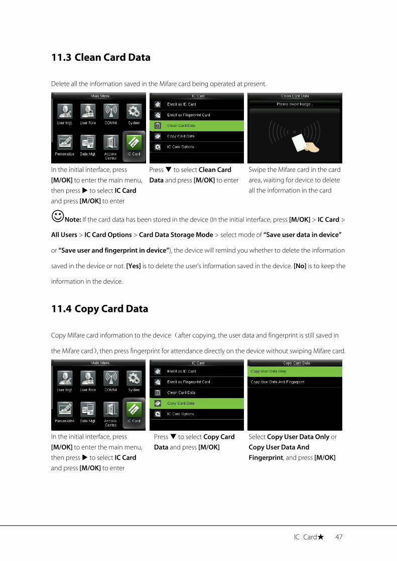
11.3 Clean Card Data
Delete all the information saved in the Mifare card being operated at present.
In the initial interface, press
[M/OK] to enter the main menu, then press to select IC Card and press [M/OK] to enter
Press to select Clean Card Data and press [M/OK] to enter
Swipe the Mifare card in the card area, waiting for device to delete all the information in the card
Note: If the card data has been stored in the device (In the initial interface, press [M/OK] > IC Card >
All Users > IC Card Options > Card Data Storage Mode > select mode of “Save user data in device”
or “Save user and fingerprint in device”), the device will remind you whether to delete the information
saved in the device or not. [Yes] is to delete the user’s information saved in the device. [No] is to keep the
information in the device.
11.4 Copy Card Data
Copy Mifare card information to the device(after copying, the user data and fingerprint is still saved in
the Mifare card), then press fingerprint for attendance directly on the device without swiping Mifare card.
In the initial interface, press
[M/OK] to enter the main menu, then press to select IC Card and press [M/OK] to enter
Press to select Copy Card Data and press [M/OK]
Select Copy User Data Only or Copy User Data And Fingerprint, and press [M/OK]
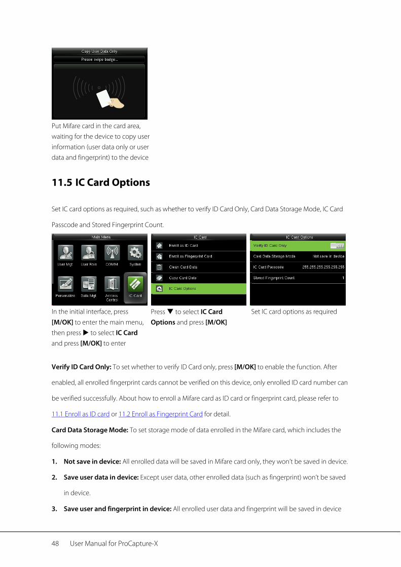
48 User Manual for ProCapture-X
Put Mifare card in the card area, waiting for the device to copy user information (user data only or user data and fingerprint) to the device
11.5 IC Card Options
Set IC card options as required, such as whether to verify ID Card Only, Card Data Storage Mode, IC Card
Passcode and Stored Fingerprint Count.
In the initial interface, press
[M/OK] to enter the main menu, then press to select IC Card and press [M/OK] to enter
Press to select IC Card Options and press [M/OK]
Set IC card options as required
Verify ID Card Only: To set whether to verify ID Card only, press [M/OK] to enable the function. After
enabled, all enrolled fingerprint cards cannot be verified on this device, only enrolled ID card number can
be verified successfully. About how to enroll a Mifare card as ID card or fingerprint card, please refer to
11.1 Enroll as ID card or 11.2 Enroll as Fingerprint Card for detail.
Card Data Storage Mode: To set storage mode of data enrolled in the Mifare card, which includes the
following modes:
1. Not save in device: All enrolled data will be saved in Mifare card only, they won’t be saved in device.
2. Save user data in device: Except user data, other enrolled data (such as fingerprint) won’t be saved
in device.
3. Save user and fingerprint in device: All enrolled user data and fingerprint will be saved in device

IC Card★ 49
and Mifare card synchronously.
IC Card Pascode: Set IC card passcode as required, which ranges from 0 to 255. After passcode is set, the
device will write passcode into the enrolled Mifare card. The Mifare card can only be used on this device.
Stored Fingerprint Count: Indicate the numbier of fingerprint stored in the card.
50 User Manual for ProCapture-X
12 USB Manager
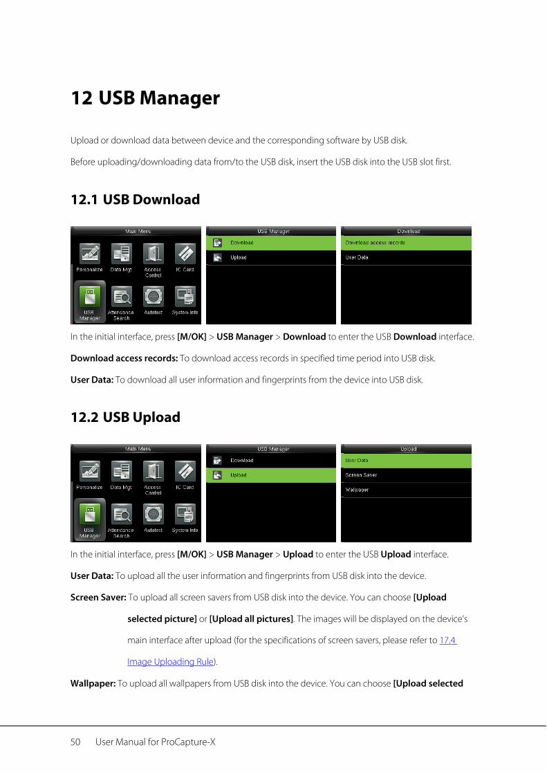
Upload or download data between device and the corresponding software by USB disk.
Before uploading/downloading data from/to the USB disk, insert the USB disk into the USB slot first.
12.1 USB Download
In the initial interface, press [M/OK] > USB Manager > Download to enter the USB Download interface.
Download access records: To download access records in specified time period into USB disk.
User Data: To download all user information and fingerprints from the device into USB disk.
12.2 USB Upload
In the initial interface, press [M/OK] > USB Manager > Upload to enter the USB Upload interface.
User Data: To upload all the user information and fingerprints from USB disk into the device.
Screen Saver: To upload all screen savers from USB disk into the device. You can choose [Upload
selected picture] or [Upload all pictures]. The images will be displayed on the device’s
main interface after upload (for the specifications of screen savers, please refer to 17.4
Image Uploading Rule).
Wallpaper: To upload all wallpapers from USB disk into the device. You can choose [Upload selected

USB Manager 51
picture] or [Upload all pictures]. The images will be displayed on the screen after upload
(for the specifications of wallpapers, please refer to 17.4 Image Uploading Rule).
52 User Manual for ProCapture-X
13 Attendance Search
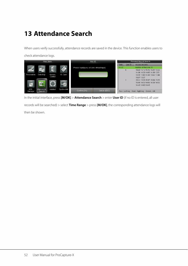
When users verify successfully, attendance records are saved in the device. This function enables users to
check attendance logs.
In the initial interface, press [M/OK] > Attendance Search > enter User ID (if no ID is entered, all user
records will be searched) > select Time Range > press [M/OK], the corresponding attendance logs will
then be shown.
Autotest 53
14 Autotest
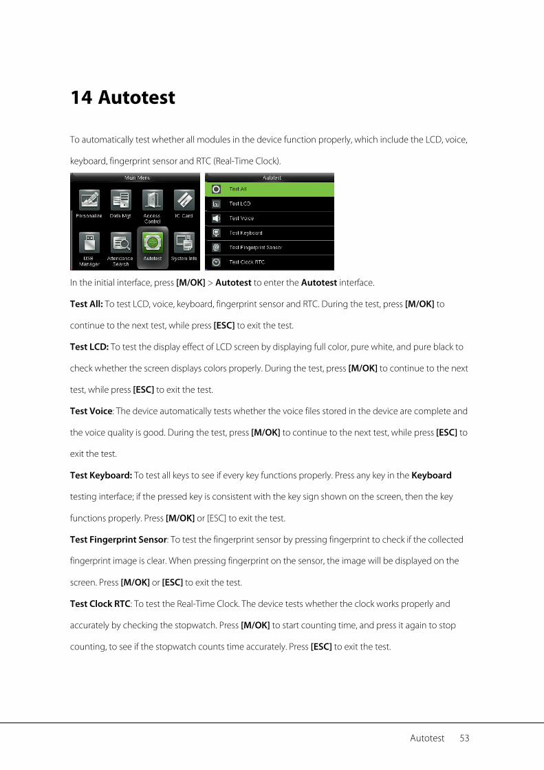
To automatically test whether all modules in the device function properly, which include the LCD, voice,
keyboard, fingerprint sensor and RTC (Real-Time Clock).
In the initial interface, press [M/OK] > Autotest to enter the Autotest interface.
Test All: To test LCD, voice, keyboard, fingerprint sensor and RTC. During the test, press [M/OK] to
continue to the next test, while press [ESC] to exit the test.
Test LCD: To test the display effect of LCD screen by displaying full color, pure white, and pure black to
check whether the screen displays colors properly. During the test, press [M/OK] to continue to the next
test, while press [ESC] to exit the test.
Test Voice: The device automatically tests whether the voice files stored in the device are complete and
the voice quality is good. During the test, press [M/OK] to continue to the next test, while press [ESC] to
exit the test.
Test Keyboard: To test all keys to see if every key functions properly. Press any key in the Keyboard
testing interface; if the pressed key is consistent with the key sign shown on the screen, then the key
functions properly. Press [M/OK] or [ESC] to exit the test.
Test Fingerprint Sensor: To test the fingerprint sensor by pressing fingerprint to check if the collected
fingerprint image is clear. When pressing fingerprint on the sensor, the image will be displayed on the
screen. Press [M/OK] or [ESC] to exit the test.
Test Clock RTC: To test the Real-Time Clock. The device tests whether the clock works properly and
accurately by checking the stopwatch. Press [M/OK] to start counting time, and press it again to stop
counting, to see if the stopwatch counts time accurately. Press [ESC] to exit the test.
54 User Manual for ProCapture-X
15 System Information
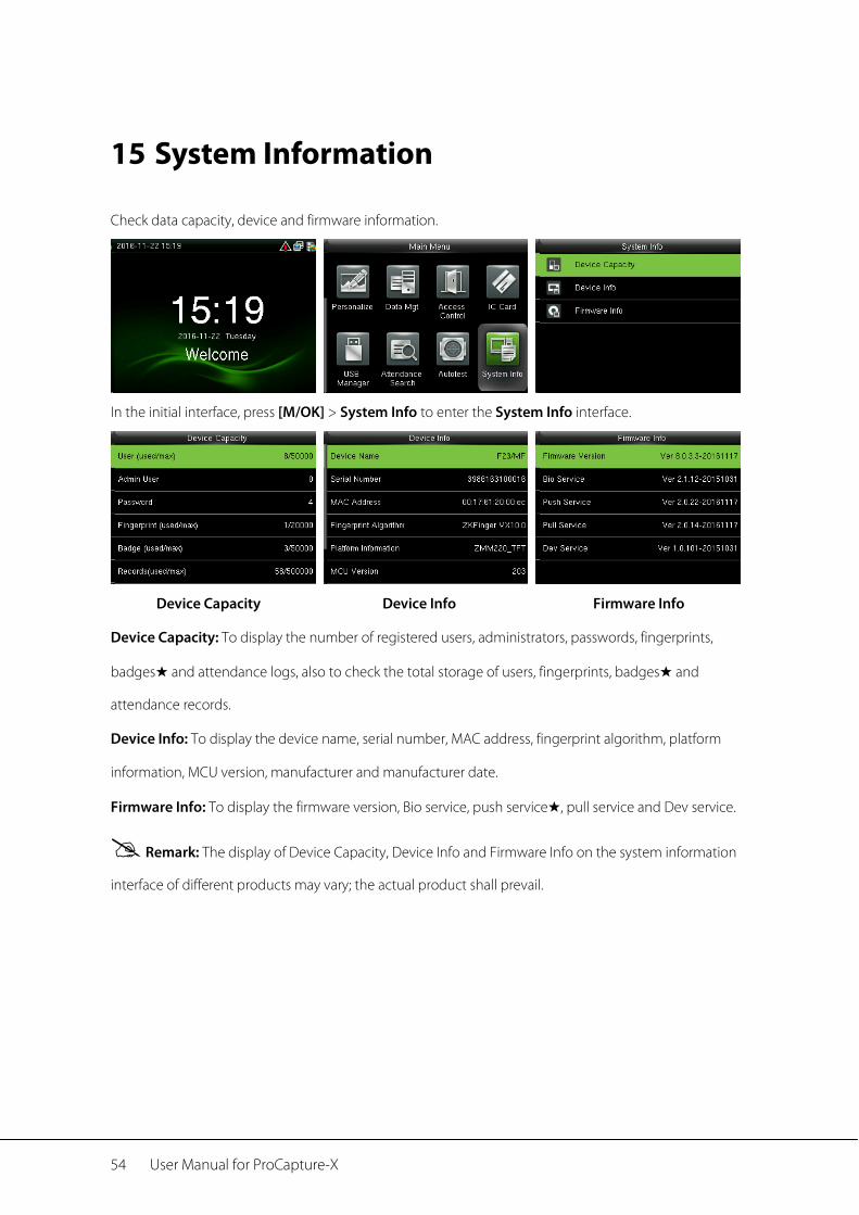
Check data capacity, device and firmware information.
In the initial interface, press [M/OK] > System Info to enter the System Info interface.
Device Capacity Device Info Firmware Info
Device Capacity: To display the number of registered users, administrators, passwords, fingerprints,
badges★ and attendance logs, also to check the total storage of users, fingerprints, badges★ and
attendance records.
Device Info: To display the device name, serial number, MAC address, fingerprint algorithm, platform
information, MCU version, manufacturer and manufacturer date.
Firmware Info: To display the firmware version, Bio service, push service★, pull service and Dev service.
Remark: The display of Device Capacity, Device Info and Firmware Info on the system information
interface of different products may vary; the actual product shall prevail.
Troubleshooting 55
16 Troubleshooting
Fingerprint sensor is not able to read and verify the fingerprint effectively.
Check whether the finger is wet, or the fingerprint sensor is wet or dusty.
Clean the finger and the fingerprint sensor and try again.
If the finger is too dry, blow air onto it and try again.
“Invalid time zone” is displayed after verification.
Contact Administrator to check if the user has the privilege to gain access within that time
Schedule.
Verification succeeds but the user cannot gain access.
Check whether the user privilege is set correctly.
Check whether the lock wiring is correct.
The Tamper Alarm rings.
Check whether the device and the back plate is fixed together; if not, the tamper switch on the
back of the device will be triggered and raises an alarm, will be shown on the top
right corner on the interface. Only when [Speaker Alarm] (Access Control > Access Control
Options > Speaker Alarm) is [ON] will the speaker raise an alarm.
56 User Manual for ProCapture-X
17 Appendices
17.1 Text Input Operation Instructions
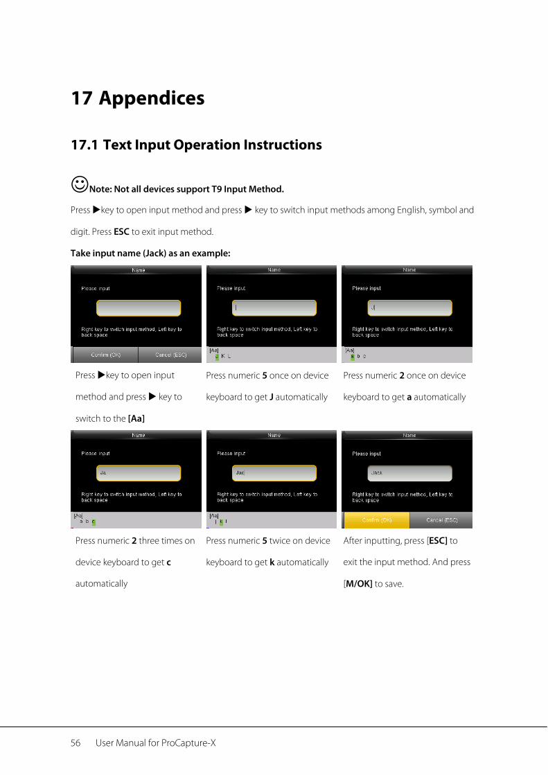
Note: Not all devices support T9 Input Method.
Press key to open input method and press key to switch input methods among English, symbol and
digit. Press ESC to exit input method.
Take input name (Jack) as an example:
Press key to open input
method and press key to
switch to the [Aa]
Press numeric 5 once on device
keyboard to get J automatically
Press numeric 2 once on device
keyboard to get a automatically
Press numeric 2 three times on
device keyboard to get c
automatically
Press numeric 5 twice on device
keyboard to get k automatically
After inputting, press [ESC] to
exit the input method. And press
[M/OK] to save.
Appendices 57
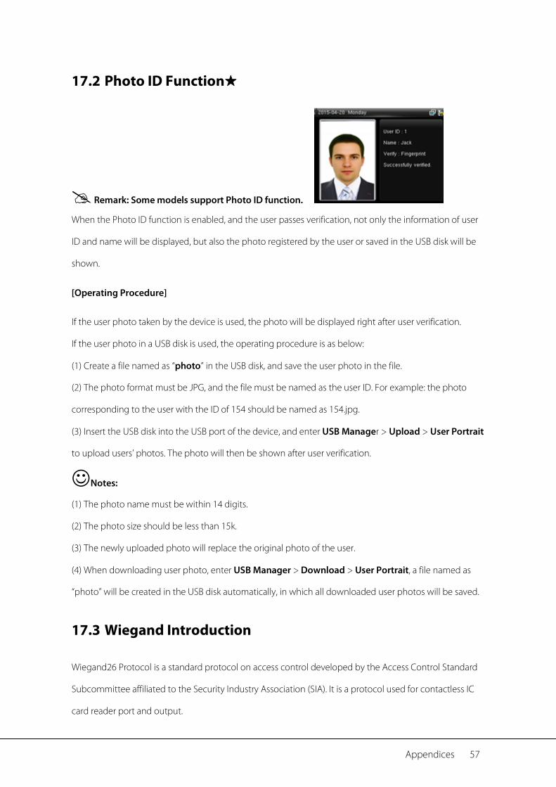
17.2 Photo ID Function★
Remark: Some models support Photo ID function.
When the Photo ID function is enabled, and the user passes verification, not only the information of user
ID and name will be displayed, but also the photo registered by the user or saved in the USB disk will be
shown.
[Operating Procedure]
If the user photo taken by the device is used, the photo will be displayed right after user verification.
If the user photo in a USB disk is used, the operating procedure is as below:
(1) Create a file named as “photo” in the USB disk, and save the user photo in the file.
(2) The photo format must be JPG, and the file must be named as the user ID. For example: the photo
corresponding to the user with the ID of 154 should be named as 154.jpg.
(3) Insert the USB disk into the USB port of the device, and enter USB Manager > Upload > User Portrait
to upload users’ photos. The photo will then be shown after user verification.
Notes:
(1) The photo name must be within 14 digits.
(2) The photo size should be less than 15k.
(3) The newly uploaded photo will replace the original photo of the user.
(4) When downloading user photo, enter USB Manager > Download > User Portrait, a file named as
“photo” will be created in the USB disk automatically, in which all downloaded user photos will be saved.
17.3 Wiegand Introduction
Wiegand26 Protocol is a standard protocol on access control developed by the Access Control Standard
Subcommittee affiliated to the Security Industry Association (SIA). It is a protocol used for contactless IC
card reader port and output.

58 User Manual for ProCapture-X
The protocol defines the port between the card reader and controller which are widely used in access
control, security and other related industries. This has standardized the work of card reader designers and
controller manufacturers. The access control devices produced by our company also apply this protocol.
Digital Signal
Figure 1 shows the sequence diagram of the card reader sending digital signal in bits to the access
controller. The Wiegand in this diagram follows the SIA access control standard protocol, which targets at
26-bit Wiegand card reader (with a pulse time within 20us to 100us and pulse hopping time within 200us
and 20ms). Data1 and Data0 signals are high level (greater than Voh) until the card reader is ready to send
a data stream. The card reader send out asynchronous low level pulse (less than vol), transmitting data
stream via Data1 or Data0 wire to access control box (as the sawtooth wave in figure 1). Data1 and Data0
pulses do not overlap or synchronize. Figure 1 shows the maximum and minimum pulse width
(successive pulses) and pulse hopping time (the time between two pulses) allowed by the F series
fingerprint access control terminals.
Table1: Pulse Time
Sign Definition Card Reader Typical Value
Tpw Pulse Width 100 µs
Tpi Pulse Interval 1 ms
Figure1: Sequence Diagram
17.4 Image Uploading Rule
1. User photo★: It is required to create a file named as “photo” under the USB disk file, and put user
photos into the file. The capacity is 3000 images at most, with each of them not exceeding 15k. The

Appendices 59
image name is x.jpg (x is the actual user ID, max. 14 digits). The photo format must be JPG.
2. Advertising image: It is required to create a file named as “advertise” under the USB disk file, and
put advertising images into the file. The capacity is 20 images with each of them not exceeding 30k.
Image name and format are not restricted.
3. Wallpaper: It is required to create a file named as “wallpaper” under the USB disk file, and put
wallpapers into the file. The capacity is 20 images with each of them not exceeding 30k. Image name
and format are not restricted.

60 User Manual for ProCapture-X
17.5 Statement on Human Rights and Privacy
Dear Customers:
Thank you for choosing the hybrid biometric products designed and manufactured by us. As a
world-renowned provider of biometric technologies and services, we pay much attention to the
compliance with the laws related to human rights and privacy in every country while constantly
performing research and development.
We hereby make the following statements:
1. All of our fingerprint recognition devices for civil use only collect the characteristic points of
fingerprints instead of the fingerprint images, and therefore no privacy issues are involved.
2. The characteristic points of fingerprints collected by our products cannot be used to restore the
original fingerprint images, and therefore no privacy issues are involved.
3. We, as the equipment provider, shall not be held legally accountable, directly or indirectly, for any
consequences arising due to the use of our products.
4. For any dispute involving the human rights or privacy when using our products, please contact your
employer directly.
Our fingerprint products for police use, or development tools support the collection of the original
fingerprint images. As for whether such a type of fingerprint collection constitutes an infringement of
your privacy, please contact the government or the final equipment provider. We, as the original
equipment manufacturer, shall not be held legally accountable for any infringement arising thereof.
The law of the People’s Republic of China has the following regulations regarding the personal
freedom:
1. Unlawful arrest, detention or search of citizens of the People's Republic of China is prohibited;
infringement of individual privacy is prohibited.
2. The personal dignity of citizens of the People's Republic of China is inviolable.
3. The home of citizens of the People's Republic of China is inviolable.
4. The freedom and privacy of correspondence of citizens of the People's Republic of China are
protected by law.
At last we stress once again that biometrics, as an advanced recognition technology, will be applied in a

Appendices 61
lot of sectors including e-commerce, banking, insurance and legal affairs. Every year people around the
globe suffer from great loss due to the insecurity of passwords. The biometric products actually provide
adequate protection for your identity under a high security environment.
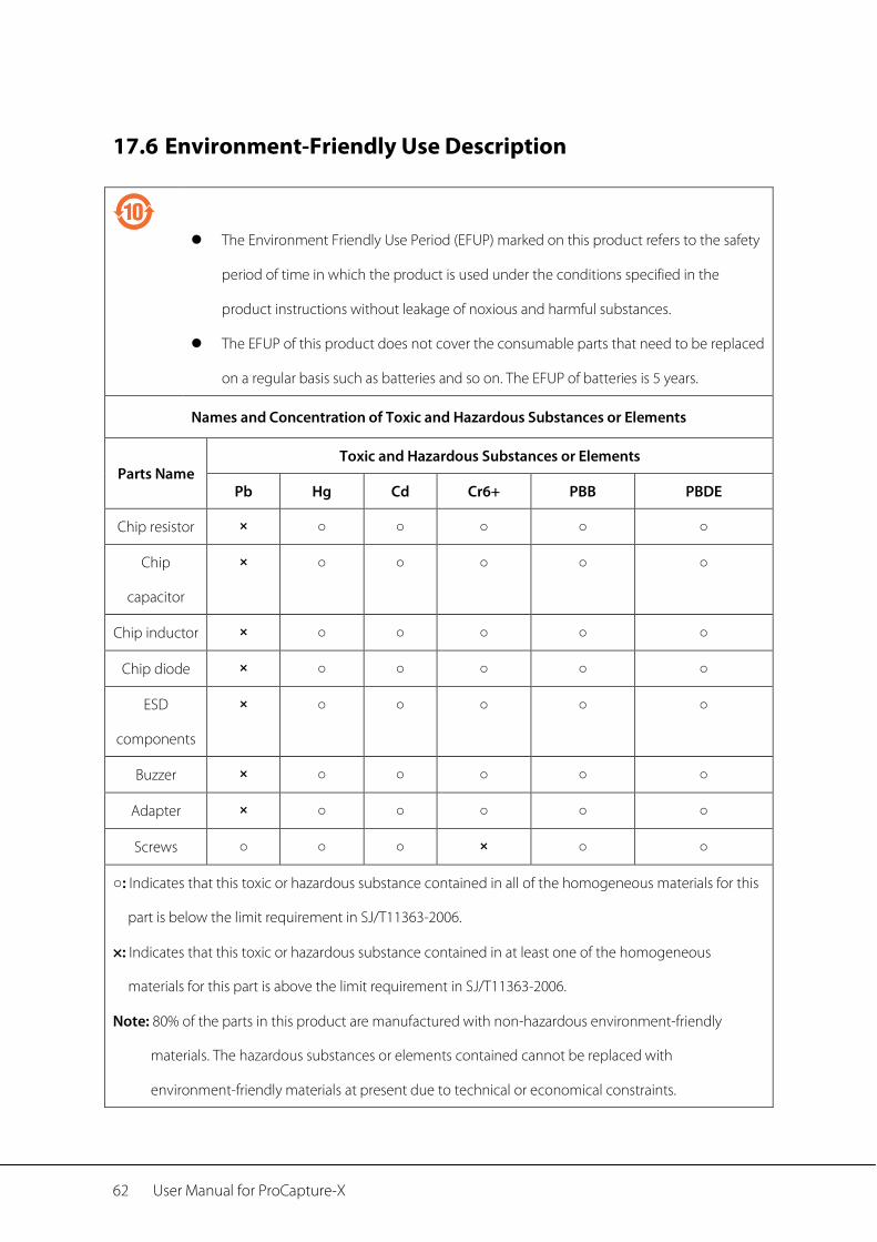
62 User Manual for ProCapture-X
17.6 Environment-Friendly Use Description
The Environment Friendly Use Period (EFUP) marked on this product refers to the safety
period of time in which the product is used under the conditions specified in the
product instructions without leakage of noxious and harmful substances.
The EFUP of this product does not cover the consumable parts that need to be replaced
on a regular basis such as batteries and so on. The EFUP of batteries is 5 years.
Names and Concentration of Toxic and Hazardous Substances or Elements
Parts Name Toxic and Hazardous Substances or Elements
Pb Hg Cd Cr6+ PBB PBDE
Chip resistor × ○ ○ ○ ○ ○
Chip
capacitor
× ○ ○ ○ ○ ○
Chip inductor × ○ ○ ○ ○ ○
Chip diode × ○ ○ ○ ○ ○
ESD
components
× ○ ○ ○ ○ ○
Buzzer × ○ ○ ○ ○ ○
Adapter × ○ ○ ○ ○ ○
Screws ○ ○ ○ × ○ ○
○: Indicates that this toxic or hazardous substance contained in all of the homogeneous materials for this
part is below the limit requirement in SJ/T11363-2006.
×: Indicates that this toxic or hazardous substance contained in at least one of the homogeneous
materials for this part is above the limit requirement in SJ/T11363-2006.
Note: 80% of the parts in this product are manufactured with non-hazardous environment-friendly
materials. The hazardous substances or elements contained cannot be replaced with
environment-friendly materials at present due to technical or economical constraints.

Appendices 63 © Copyright 2014. ZKTeco Inc. ZKTeco Logo is a registered trademark of ZKTeco or a related company. All other product and
company names mentioned are used for.