Embed Size (px)
DESCRIPTION
User Manual Wago Dali power measurement terminals V0.2
Citation preview

User Manual WAGODALI and power measurement terminal
V 0.2
&

2
®®
Latest Update: April 2013All software-related descriptions refer to the C2021 software. An update is recommended for older versions of the system. Small deviations of the descriptions are possible and due to changes in the software. All brands and logos are registered trademarks and are the property of the respective holders of the rights
Copyright
All rights reserved. No parts of this document may be reproduced or transmitted in any form by any means, electronic or mechanical, without the prior written authorization of its legal owner.
If this publication is made available on Ekon GmbH media, Ekon gives its consent to downloading and printing copies of the content provided in this file only for private use and not for redistribution. No part of this publication may be modified, altered or used for commercial purposes. Ekon GmbH is not liable for the damages which arise from the use of an illegal modified or altered publication.
All products correspond to the directly applicable EU regulations and guidelines.
3
3
Table of Contents
1. Electrical connection and addressing . . . . . . . . . . . . . . . . . . . . . . . . . . . . . . . . . . . . . . . . 4
1.1 RS485 MODBUS RTU . . . . . . . . . . . . . . . . . . . . . . . . . . . . . . . . . . . . . . . . . . . . . . . . . . . . . . . . . . . . . . . . . . . . . . . . 41.2 MODBUS TCP/IP . . . . . . . . . . . . . . . . . . . . . . . . . . . . . . . . . . . . . . . . . . . . . . . . . . . . . . . . . . . . . . . . . . . . . . . . . . . . . 71.3 Utilisation of several bus couplers . . . . . . . . . . . . . . . . . . . . . . . . . . . . . . . . . . . . . . . . . . . . . . . . . . . . . . . . . . . 81.4 Numbering of connections . . . . . . . . . . . . . . . . . . . . . . . . . . . . . . . . . . . . . . . . . . . . . . . . . . . . . . . . . . . . . . . . . 9
2. Software activation at myGEKKO . . . . . . . . . . . . . . . . . . . . . . . . . . . . . . . . . . . . . . . . . . . 10
2.1 Main configuration . . . . . . . . . . . . . . . . . . . . . . . . . . . . . . . . . . . . . . . . . . . . . . . . . . . . . . . . . . . . . . . . . . . . . . . . . 102.2 DALI configuration . . . . . . . . . . . . . . . . . . . . . . . . . . . . . . . . . . . . . . . . . . . . . . . . . . . . . . . . . . . . . . . . . . . . . . . . . 112.3 Power measurement terminal . . . . . . . . . . . . . . . . . . . . . . . . . . . . . . . . . . . . . . . . . . . . . . . . . . . . . . . . . . . . . . 13
3. Notes . . . . . . . . . . . . . . . . . . . . . . . . . . . . . . . . . . . . . . . . . . . . . . . . . . . . . . . . . . . . . . . . . . . . . . 14
4
1. Electrical connection and addressing1.1 RS485 MODBUS RTU
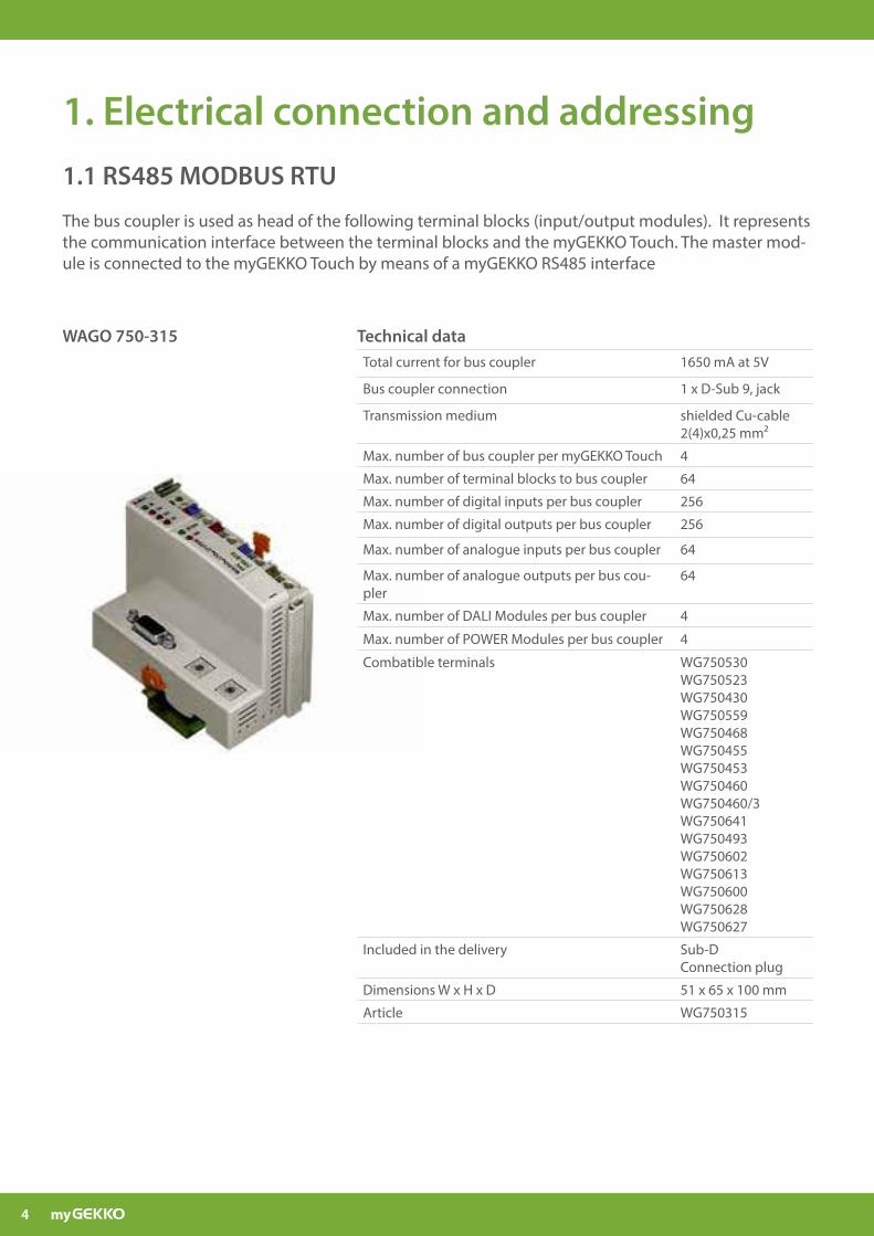
The bus coupler is used as head of the following terminal blocks (input/output modules). It represents the communication interface between the terminal blocks and the myGEKKO Touch. The master mod-ule is connected to the myGEKKO Touch by means of a myGEKKO RS485 interface
Technical dataTotal current for bus coupler 1650 mA at 5V
Bus coupler connection 1 x D-Sub 9, jack
Transmission medium shielded Cu-cable 2(4)x0,25 mm²
Max. number of bus coupler per myGEKKO Touch 4
Max. number of terminal blocks to bus coupler 64
Max. number of digital inputs per bus coupler 256
Max. number of digital outputs per bus coupler 256
Max. number of analogue inputs per bus coupler 64
Max. number of analogue outputs per bus cou-pler
64
Max. number of DALI Modules per bus coupler 4
Max. number of POWER Modules per bus coupler 4
Combatible terminals WG750530WG750523WG750430WG750559WG750468WG750455WG750453WG750460WG750460/3WG750641WG750493WG750602WG750613WG750600WG750628WG750627
Included in the delivery Sub-D Connection plug
Dimensions W x H x D 51 x 65 x 100 mm
Article WG750315
WAGO 750-315
5
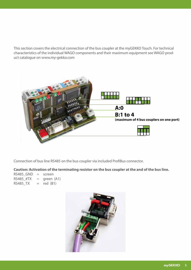
Connection of bus line RS485 on the bus coupler via included ProfiBus connector.
Caution: Activation of the terminating resistor on the bus coupler at the and of the bus line.RS485_GND = screenRS485_#TX = green (A1)RS485_TX = red (B1)
B:1 to 4(maximum of 4 bus couplers on one port)
A:0
This section covers the electrical connection of the bus coupler at the myGEKKO Touch. For technical characteristics of the individual WAGO components and their maximum equipment see WAGO prod-uct catalogue on www.my-gekko.com
6
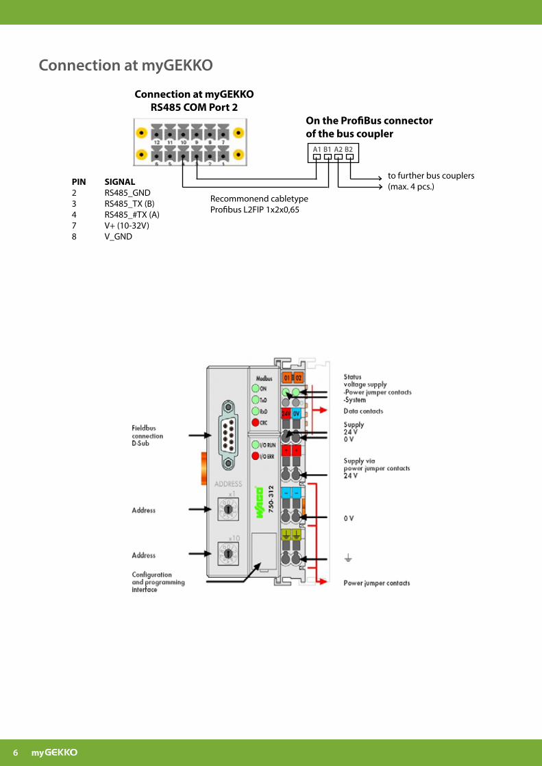
PIN SIGNAL2 RS485_GND3 RS485_TX (B)4 RS485_#TX (A)7 V+ (10-32V)8 V_GND
Connection at myGEKKO RS485 COM Port 2
On the ProfiBus connector of the bus coupler
A1 B1 B2A2
Recommonend cabletypeProfibus L2FIP 1x2x0,65
to further bus couplers (max. 4 pcs.)
Connection at myGEKKO
7
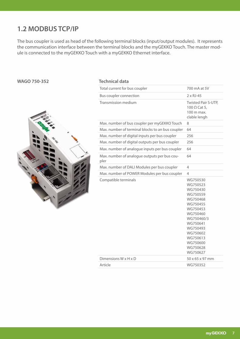
1.2 MODBUS TCP/IP
The bus coupler is used as head of the following terminal blocks (input/output modules). It represents the communication interface between the terminal blocks and the myGEKKO Touch. The master mod-ule is connected to the myGEKKO Touch with a myGEKKO Ethernet interface.
Technical dataTotal current for bus coupler 700 mA at 5V
Bus coupler connection 2 x RJ-45
Transmission medium Twisted Pair S-UTP, 100 Ω Cat 5, 100 m max. clable lengh
Max. number of bus coupler per myGEKKO Touch 8
Max. number of terminal blocks to an bus coupler 64
Max. number of digital inputs per bus coupler 256
Max. number of digital outputs per bus coupler 256
Max. number of analogue inputs per bus coupler 64
Max. number of analogue outputs per bus cou-pler
64
Max. number of DALI Modules per bus coupler 4
Max. number of POWER Modules per bus coupler 4
Compatible terminals WG750530WG750523WG750430WG750559WG750468WG750455WG750453WG750460WG750460/3WG750641WG750493WG750602WG750613WG750600WG750628WG750627
Dimensions W x H x D 50 x 65 x 97 mm
Article WG750352
WAGO 750-352
8
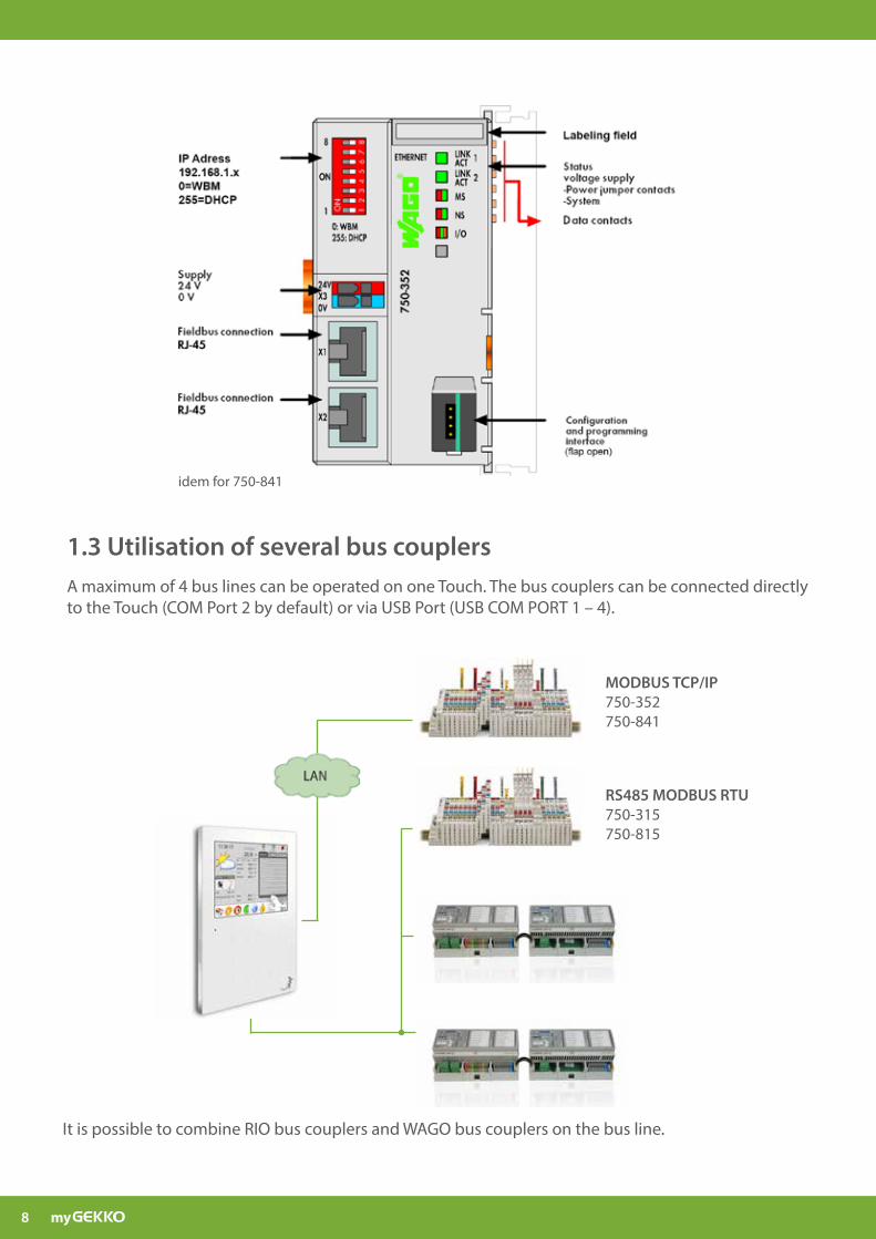
1.3 Utilisation of several bus couplersA maximum of 4 bus lines can be operated on one Touch. The bus couplers can be connected directly to the Touch (COM Port 2 by default) or via USB Port (USB COM PORT 1 – 4).
It is possible to combine RIO bus couplers and WAGO bus couplers on the bus line.
RS485 MODBUS RTU750-315750-815
MODBUS TCP/IP750-352750-841
idem for 750-841
9
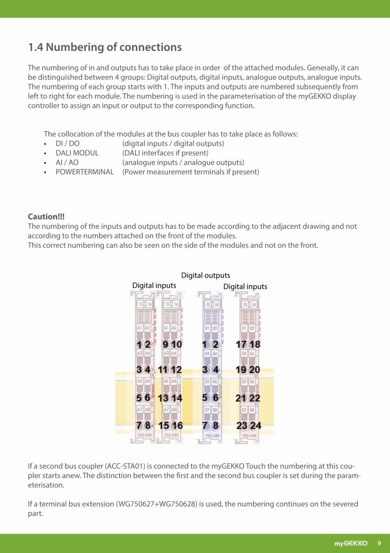
The numbering of in and outputs has to take place in order of the attached modules. Generally, it can be distinguished between 4 groups: Digital outputs, digital inputs, analogue outputs, analogue inputs.The numbering of each group starts with 1. The inputs and outputs are numbered subsequently from left to right for each module. The numbering is used in the parameterisation of the myGEKKO display controller to assign an input or output to the corresponding function.
The collocation of the modules at the bus coupler has to take place as follows:• DI / DO (digital inputs / digital outputs)• DALI MODUL (DALI interfaces if present)• AI / AO (analogue inputs / analogue outputs)• POWERTERMINAL (Power measurement terminals if present)
Caution!!!The numbering of the inputs and outputs has to be made according to the adjacent drawing and not according to the numbers attached on the front of the modules.This correct numbering can also be seen on the side of the modules and not on the front.
Digital inputs Digital inputsDigital outputs
If a second bus coupler (ACC-STA01) is connected to the myGEKKO Touch the numbering at this cou-pler starts anew. The distinction between the first and the second bus coupler is set during the param-eterisation.
If a terminal bus extension (WG750627+WG750628) is used, the numbering continues on the severed part.
1.4 Numbering of connections
10
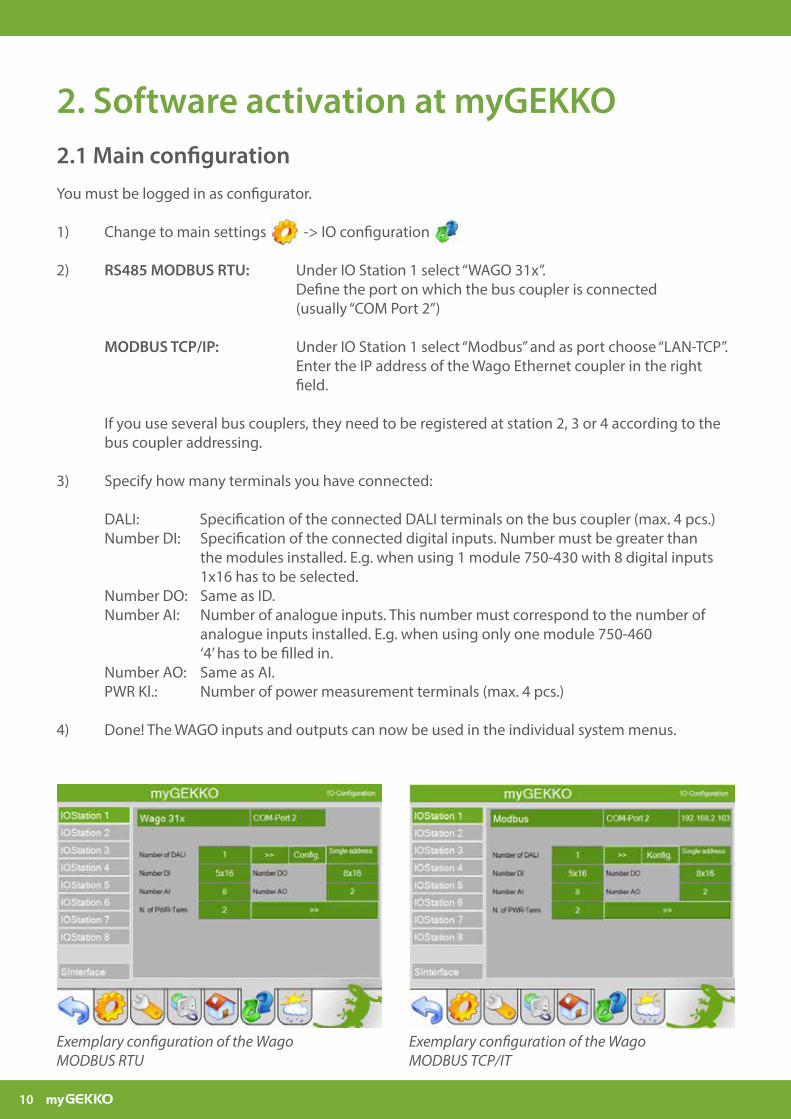
2. Software activation at myGEKKO
You must be logged in as configurator.
1) Change to main settings -> IO configuration
2) RS485 MODBUS RTU: Under IO Station 1 select “WAGO 31x”. Define the port on which the bus coupler is connected (usually “COM Port 2”) MODBUS TCP/IP: Under IO Station 1 select “Modbus” and as port choose “LAN-TCP”. Enter the IP address of the Wago Ethernet coupler in the right field.
If you use several bus couplers, they need to be registered at station 2, 3 or 4 according to the bus coupler addressing.
3) Specify how many terminals you have connected: DALI: Specification of the connected DALI terminals on the bus coupler (max. 4 pcs.) Number DI: Specification of the connected digital inputs. Number must be greater than the modules installed. E.g. when using 1 module 750-430 with 8 digital inputs 1x16 has to be selected. Number DO: Same as ID. Number AI: Number of analogue inputs. This number must correspond to the number of analogue inputs installed. E.g. when using only one module 750-460 ‘4’ has to be filled in. Number AO: Same as AI. PWR Kl.: Number of power measurement terminals (max. 4 pcs.)
4) Done! The WAGO inputs and outputs can now be used in the individual system menus.
Exemplary configuration of the Wago MODBUS RTU
Exemplary configuration of the Wago MODBUS TCP/IT
2.1 Main configuration
11
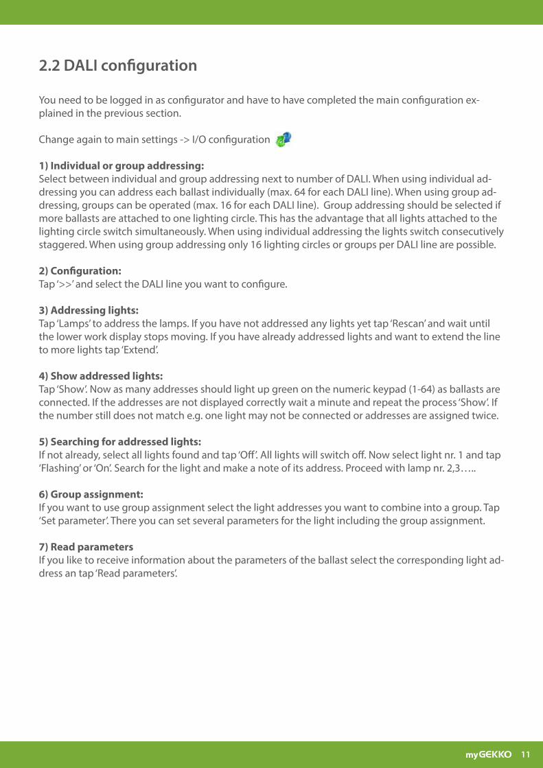
2.2 DALI configuration
You need to be logged in as configurator and have to have completed the main configuration ex-plained in the previous section.
Change again to main settings -> I/O configuration
1) Individual or group addressing:Select between individual and group addressing next to number of DALI. When using individual ad-dressing you can address each ballast individually (max. 64 for each DALI line). When using group ad-dressing, groups can be operated (max. 16 for each DALI line). Group addressing should be selected if more ballasts are attached to one lighting circle. This has the advantage that all lights attached to the lighting circle switch simultaneously. When using individual addressing the lights switch consecutively staggered. When using group addressing only 16 lighting circles or groups per DALI line are possible.
2) Configuration:Tap ‘>>’ and select the DALI line you want to configure.
3) Addressing lights:Tap ‘Lamps’ to address the lamps. If you have not addressed any lights yet tap ‘Rescan’ and wait until the lower work display stops moving. If you have already addressed lights and want to extend the line to more lights tap ‘Extend’.
4) Show addressed lights:Tap ‘Show’. Now as many addresses should light up green on the numeric keypad (1-64) as ballasts are connected. If the addresses are not displayed correctly wait a minute and repeat the process ‘Show’. If the number still does not match e.g. one light may not be connected or addresses are assigned twice.
5) Searching for addressed lights:If not already, select all lights found and tap ‘Off’. All lights will switch off. Now select light nr. 1 and tap ‘Flashing’ or ‘On’. Search for the light and make a note of its address. Proceed with lamp nr. 2,3…..
6) Group assignment:If you want to use group assignment select the light addresses you want to combine into a group. Tap ‘Set parameter’. There you can set several parameters for the light including the group assignment.
7) Read parametersIf you like to receive information about the parameters of the ballast select the corresponding light ad-dress an tap ‘Read parameters’.
12
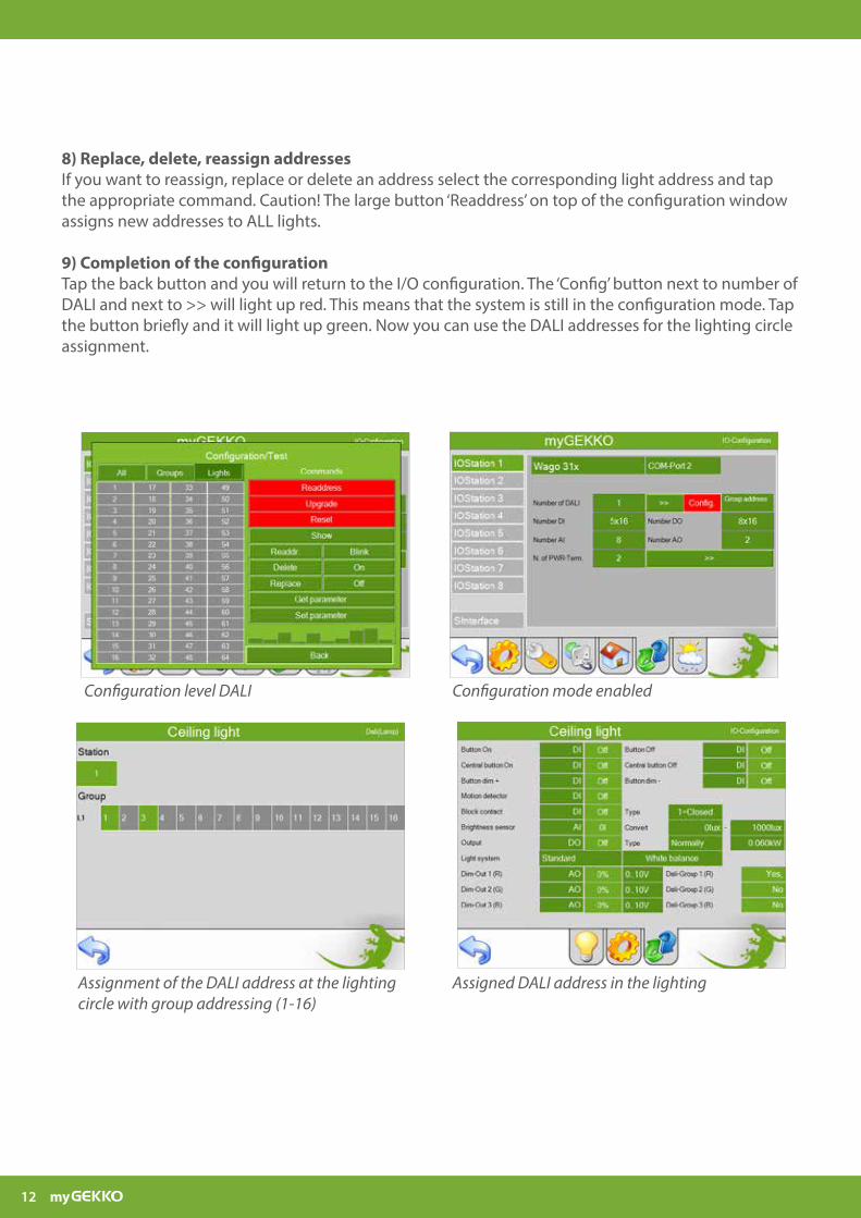
8) Replace, delete, reassign addressesIf you want to reassign, replace or delete an address select the corresponding light address and tap the appropriate command. Caution! The large button ‘Readdress’ on top of the configuration window assigns new addresses to ALL lights.
9) Completion of the configurationTap the back button and you will return to the I/O configuration. The ‘Config’ button next to number of DALI and next to >> will light up red. This means that the system is still in the configuration mode. Tap the button briefly and it will light up green. Now you can use the DALI addresses for the lighting circle assignment.
Configuration level DALI Configuration mode enabled
Assignment of the DALI address at the lighting circle with group addressing (1-16)
Assigned DALI address in the lighting
13
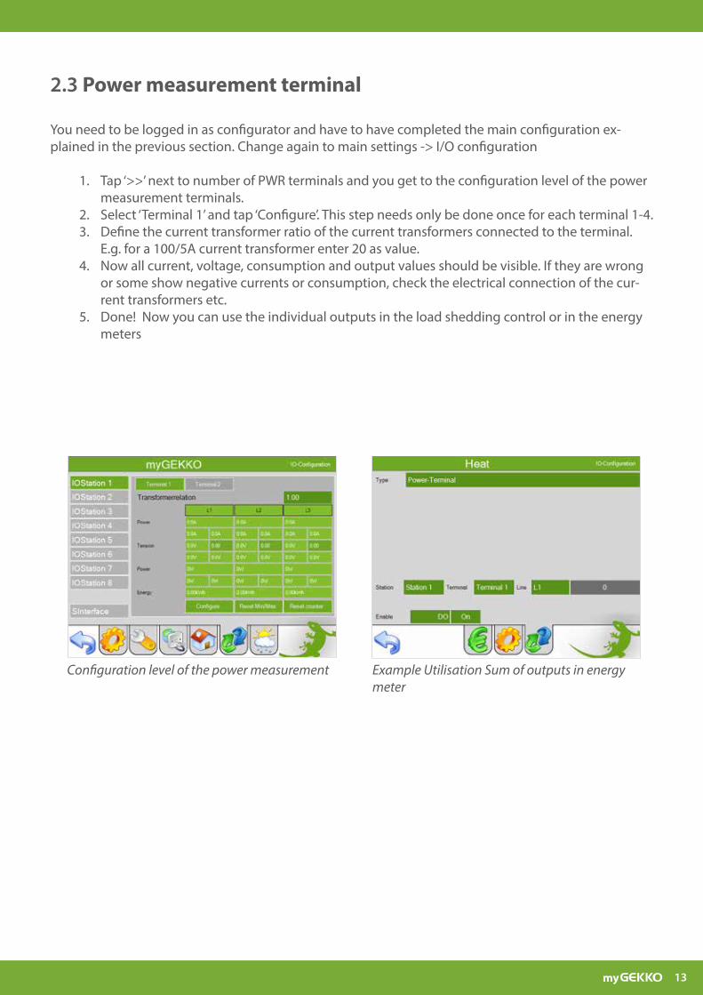
2.3 Power measurement terminal
You need to be logged in as configurator and have to have completed the main configuration ex-plained in the previous section. Change again to main settings -> I/O configuration
1. Tap ‘>>’ next to number of PWR terminals and you get to the configuration level of the power measurement terminals.
2. Select ‘Terminal 1’ and tap ‘Configure’. This step needs only be done once for each terminal 1-4. 3. Define the current transformer ratio of the current transformers connected to the terminal.
E.g. for a 100/5A current transformer enter 20 as value.4. Now all current, voltage, consumption and output values should be visible. If they are wrong
or some show negative currents or consumption, check the electrical connection of the cur-rent transformers etc.
5. Done! Now you can use the individual outputs in the load shedding control or in the energy meters
Configuration level of the power measurement Example Utilisation Sum of outputs in energy meter
14
3. Notes

15

16
www.my-gekko.com
A first class product of Europe!The result of a close collaboration between Italy, Switzerland and Germany