Embed Size (px)
Citation preview
1
User Manual
2
Introduction
Regulated Negative Pressure Wound Therapy (RNPT) has revolutionized and enhanced
wound care during the last two decades. Vcare ® utilizes RNPT by multiple
mechanisms of action, to remove fluids and infectious materials, help protect the wound
environment, aid promote perfusion and provide moist healing environment, help draw
together wound edges and promotes granulation.
RNPT is the controlled application of sub-atmospheric pressure to a wound using a
therapy unit to intermittently or continuously apply negative pressure to a specialized
wound dressing to help promote wound healing. The wound dressing is a resilient, open-
cell polyurethane foam surface dressing and is sealed with an adhesive drape that
contains the sub-atmospheric pressure at the wound site. Important safety features
enhances patient safety by regulating pressure at the wound site and warning possibility
of uncontrolled bleeding. Additionally, the Vcare ® helps direct drainage to a specially
designed canister that reduces the risk of exposure to exudates, fluids and infectious
materials
Intended Use
The Vcare ® is indicated for wound management via application of a pre-set
level of continuous or intermittent negative pressure to the wound for removal of
fluids, including wound exudates, irrigation fluids, and infectious materials. It is
intended for management of chronic, acute, traumatic, sub-acute and dehisced
wounds, partial-thickness burns, ulcers (i.e., diabetic or pressure), flaps and
grafts.
This user manual includes important information and instructions for correct and
safe operation of the Vcare ® device. It is provided for training of personnel and
as a reference for users.
Caution: When applying Vcare ® wound treatment products, be sure to
apply the product according to manufacturer’s instructions for use.
3
Caution: Not for use among children below the age of 6. Before using consult with licensed and specifically trained physician.
Important Safety Warnings
Pay special attention when treatment is applied for elderly and young patient with
sensitive for highly delicate skin. The care provider should have a vast establish
experience with vacuum treatment in order to define the vacuum that should be
applied, the mode of operation and the duration of exposure to treatment.
In order to reduce potential risk for serious or fatal injury, prior to use read and
follow the instructions for use. This user manual is part of the Vcare ® system. All
safety information and warnings must be read prior to use.
The Vcare ® is intended to be operated by licensed and specifically trained
medical staff. Treatment mode and parameters must be set only by physicians or
dedicatedly trained nurses.
Important
Do not use the Vcare ® system without consulting and supervision of a physician. Read
through and follow the user instructions and safety information before using the Vcare
® system. Using the system without physician supervision or without following the
clinical guidelines on this manual may risk the patient and may result in serious injury.
For safe and proper operation of the Vcare ® system, the safeguards
below must be followed:
The operation of this product must be according to this manual.
No modification of the Vcare ® system is allowed without prior authorization of IVT
Medical Ltd.
If this equipment is modified, appropriate inspection and testing must be conducted
by IVT Medical Ltd. service personnel to ensure continued safe use of equipment.
Assembly, adjustments, modifications, maintenance and/or repair of the Vcare ®
system must be carried out by a qualified personnel authorized by IVT Medical Ltd.
4
To avoid risk of electric shock, the Vcare ® unit must only be connected to a supply
main with protective earth.
Do not connect this product to damaged external power supply.
Do not insert any object into any opening or tubing of the Vcare ® unit.
The Vcare ® disposables are intended to be used only with the Vcare ® unit.
Do not shake or rock the Vcare ® unit.
The Vcare ® unit should not be placed over heated surfaces.
Special precautions regarding EMC must be taken when installing and preparing the
Vcare ® unit for operation according to the EMC section in this manual.
Portable and mobile RF communication equipments may produce Electromagnetic
interference. If interference is suspected, separate the equipment and contact your
service provider. For further details, see EMC section in this manual.
Do not touch the external fuse or fuse holder and the patient simultaneously.
Do not spill any fluids on the Vcare ® unit or any of its parts.
If any liquid is spilled on the system, disconnect the unit from its external power
adapter and wipe using an absorbent cloth. Before reconnecting the unit, make sure
that the power connector is dry. If the Vcare ® is not working properly, contact IVT
Medical or local authorized distributer.
Disposal
o The Vcare ® unit must be returned to IVT Medical at the end of its
operational life, i.e. following 5,000 hours of the internal pump operation.
o All disposables (Vcare ® wound dressing, drapes, collection canister, tubing,
connectors and filters) should be handled and discarded according to
institutional procedures and local, state and federal regulations.
o If not disposed properly, contact with the disposables may lead to
contamination or super infection.
5
Safety Information
Disposables
The disposables of the Vcare ® system are intended for single use only.
Do not re-use or re-sterile the disposables as this may cause infection to the
wound.
Warning: Do not use non-sterile disposables.
Always dispose the wound dressing, collection canister, drapes and tubing according to
hospital and bio-hazard protocols and according to institutional procedures and local,
state and federal environmental regulations.
Indications for use of Vcare ® system
The Vcare ® system is indicated for wound management via application of a
pre-set level of continuous or intermittent negative pressure. The Vcare ®
system may promote wound healing by either removal of excess exudate or
irrigation fluids and infectious materials. It is intended for management of chronic,
acute, traumatic, sub-acute and dehisced wounds, partial-thickness burns, ulcers
(i.e., diabetic or pressure), flaps and grafts.
Specifically, the Vcare ® system is indicated to be used with the following wounds:
Chronic wounds
o Wounds in diabetic and PVD-affected limbs
o Decubitus ulcers
o Trophic ulcers
o Venostatic, arterial, diabetic, neuropathic, post irradiation, and pressure sores
Dehisced and infected surgical wounds and complications of failed sternal closures
Traumatic Wounds
Deep and partial-thickness small-to-medium size burns
Treatment of skin grafts and flaps
Extensive tissue losses
Treatment of open fractures
Crush injuries
Compartment syndromes
6
Contraindications
Vcare ® system is contraindicated in case of:
Uncontrolled bleeding.
o Following trauma
o Following surgery
o Patients with hematological disorders
o Vcare ® system should be restricted in patients with open wounds who are
treated with anticoagulants or suffer hematological disorders.
A meticulous homeostasis should be established prior to the application of Vcare ®
system. The care provider should ensure that no exposed blood vessels, nerves,
areas with fresh vascular anastomosis and internal organs are in direct contact with
the vacuum system.
Ulcerated malignant wounds are contraindicated for treatment by Vcare ® system
as vacuum treatment may accelerate tumor growth within the wound cavity (with
exception of palliative care to enhance quality of life).
Note: Treatment of long standing unhealed wounds should be evaluated for possible
malignancy (by biopsy of ulcers) prior to RNPT.
Vcare ® system is contraindicated for treatment of non-enteric unexplored fistulas.
Exploration of a fistula and determinations of its extensions and content should
precede Vcare ® application.
The use of Vcare ® system is contraindicated in apparent anaerobic infection.
Vcare ® system is restricted to small and medium size burns, as treatment of wide
partial-thickness and deep burns may lead to extensive extra-cellular fluid loss and
electrolyte imbalance by the applied suction.
Vcare ® system may be ineffective or contraindicated in case of:
Necrotic tissue with eschar
Areas where adhesive tape application is limited (dense hairy areas, mucus
membranes, and joints that cannot be fixated).
General Guidelines
7
Always use the lowest effective negative pressure.
Safety measures regarding the use of Vcare ® system should always be
considered and implemented.
Conservatively debride necrotic tissue prior to the use of vacuum treatment with
the Vcare ® system.
Evaluate the need for initiation and cessation of systemic antibiotic treatment in
conjunction with the Vcare ® system.
Vacuum levels in Vcare ® system should be tailored to each specific wound and
adjusted according to patient's clinical condition. General guidelines and
recommended vacuum levels are shown in the table below.
Inexperienced personnel is advised to always use the cyclic-continuous mode or
consult a trained physician regarding the treatment settings before using the Vcare
® system.
When applying external vacuum - make sure that the vacuum level supplied from
the external vacuum source is 50 mmHg above the desired working pressure but
should not exceed 200 mmHg.
It is recommended to connect the unit to an external vacuum source by a pressure
regulator.
The external vacuum tube must be disconnected from the unit when external
vacuum is not in use.
When working with the unit’s internal pump, make sure that the external vacuum
tube is not connected to the unit.
The device must be operated in a quite environment with background noise of no
more than 45-50dB
A portable modality of utilization enables via a mobile stand.
IV (intravenous) medication administration by IV pump can be integrated with
Vcare ® treatment. The pump shall be hanged on IV pole that structured in the
mobile stand or being placed on a flat surface that is higher than the Vcare ® unit.
Warnings regarding clinical application of the Vcare ® system
Bleeding and infection should be anticipated during the use of RNPT.
8
When bleeding risk is anticipated to be high (early following trauma or surgery),
working negative pressure levels should be set as low as possible and should not
exceed a maximum of 80 mmHg.
While working on stiff surfaces, as in clinical cases of low- perfused tissues like
PVD, diabetic, traumatic wounds, low vacuum is essential in order to prevent
tissue ischemia.
Maximal Flow Rate Setting: Maximal flow rate from the wound through the tubing
to the collection canister is pre-set as default to be up to 100 ml/hr. In case that the
flow exceeds this limit, an alarm is activated and the suction apparatus shuts
down. It is obligatory to maintain this default setting. Increasing the maximal flow
rate allowed from the wound may eliminate control of acute bleeding.
Alarms Setting: Alarms are pre-set as default to audio & visual alarms. Any alarm
condition will be indicated by audio (a repetitive beeping sound) and visual (A
flickering triangle symbol in the middle of the display screen and an indication
LED) alarms. Changing this pre-setting should be considered carefully. Change of
alarms settings may prevent from the care-giver the detection of critical indications
regarding the vacuum treatment.
Never leave a wound covered for an extended time without effective negative
pressure. As the Vcare ® system is operating, fluids are discharged and
constantly evacuates from the wound. Once the vacuum is halted, the system is at
risk of becoming occlusive, which might lead to infection.
Wound dressing must be replaced according to the clinical guidelines or
physician’s judgment in order to prevent super infection to the wound.
Constant efficient negative pressure should be applied to the wound in order to
avoid bacterial overgrowth and super-infection. If vacuum is ineffective for over 30
min, aeration of the wound by removal of occlusive dressing or other form of
ventilation should be considered.
The Vcare ® system should not be used in cases with apparent or suspected
anaerobic infection.
Negative pressure may exacerbate uncontrolled bleeding. All precautions should
be taken in order to avoid uncontrolled bleeding and the immediate cessation of
RNPT in case of excessive bleeding should be executed.
Avoid high negative pressure during the early stage of trauma treatment.
9
Severe, life-threatening bleeding may result from the application of vacuum in
treatment of acute trauma, immediately after surgery, at early stages following
debridement of wounds, in patients treated with anticoagulants or suffering from
hematological disorders.
Setting high values of negative pressures may induce ischemia and may
aggravate clinical ischemic conditions such as in peripheral vascular disease,
diabetic leg, and traumatized tissue.
Excessive topical pressure may lead to compromised blood circulation and
impairment of wound healing.
Treatment of long standing unhealed wounds should be evaluated for possible
malignancy by biopsy of ulcers.
Treatment of Diabetic Foot
Diabetic foot patients with an ankle-brachial ratio less than 0.5 should be treated
with the lowest effective negative pressure and should be closely monitored for
distal perfusion impairment, mainly when having circumferential vacuum wound
dressing.
Treatment of Contaminated Wounds
High levels of negative pressure (deeper vacuum) may be needed for the initial
treatment of heavily contaminated wounds.
Treatment of Tissue Ischemia
Tissue ischemia can be managed and avoided by short term higher negative
pressure values applied in an intermittent mode.
Dot not place the mold or apply vacuum over a healthy tissue. Applying vacuum on
healthy tissue may cause irritation and damage the skin.
Clinical Guidelines of the Vcare ® system
The clinically based range of recommended vacuum pressure, level range, span,
frequency of operation, mode and exchange of dressing in Vcare ® system for various
conditions is presented in the following table. The practicing physician should recognize
the need for specific settings for vacuum work/pause ratio, and the frequency of dressing
changes adjusted to the varying clinical conditions for each individual wound.
Guidelines for clinical application of Vcare ® system
11
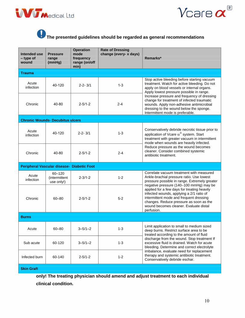
The presented guidelines should be regarded as general recommendations
only! The treating physician should amend and adjust treatment to each individual
clinical condition.
Intended use – type of wound
Pressure range (mmHg)
Operation mode frequency range (on/off min)
Rate of Dressing change (every- x days)
Remarks*
Trauma
Acute infection
04-024 2-2- 3/1 0-3
Stop active bleeding before starting vacuum treatment. Watch for active bleeding. Do not apply on blood vessels or internal organs. Apply lowest pressure possible in range. Increase pressure and frequency of dressing change for treatment of infected traumatic wounds. Apply non-adhesive antimicrobial dressing to the wound below the sponge. Intermittent mode is preferable.
Chronic 04-04 2-510-2 2-4
Chronic Wounds- Decubitus ulcers
Acute infection
04-024 2-2- 3/1 1-3 Conservatively debride necrotic tissue prior to
application of Vcare ® system. Start
treatment with greater vacuum in intermittent mode when wounds are heavily infected. Reduce pressure as the wound becomes cleaner. Consider combined systemic antibiotic treatment.
Chronic 04-04 2-510-2 2-4
Peripheral Vascular disease- Diabetic Foot
Acute infection
60–120 (intermittent use only!)
2-310-2 1-2
Correlate vacuum treatment with measured Ankle-brachial pressure ratio. Use lowest pressure possible in range. Extremely greater negative pressure (140–100 mmHg) may be applied for a few days for treating heavily infected wounds, applying a 2/1 ratio of intermittent mode and frequent dressing changes. Reduce pressure as soon as the wound becomes cleaner. Evaluate distal perfusion.
Chronic 60–80 2-510-2 5-2
Burns
Acute 60–80 3–5/1–2 1-3 Limit application to small to medium sized deep burns. Restrict surface area to be treated according to the amount of fluid discharge from the wound. Stop treatment If excessive fluid is drained. Watch for acute bleeding. Determine and correct electrolyte imbalance, evaluate need for replacement therapy and systemic antibiotic treatment. Conservatively debride eschar.
Sub acute 60-120 3–5/1–2 1-3
Infected burn 60-140 2-5/1-2 1-2
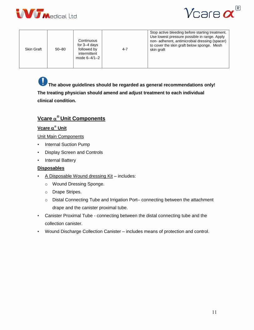
Skin Graft
11
The above guidelines should be regarded as general recommendations only!
The treating physician should amend and adjust treatment to each individual
clinical condition.
Vcare ® Unit Components
Vcare ® Unit
Unit Main Components
• Internal Suction Pump
• Display Screen and Controls
• Internal Battery
Disposables
• A Disposable Wound dressing Kit – includes:
o Wound Dressing Sponge.
o Drape Stripes.
o Distal Connecting Tube and Irrigation Port– connecting between the attachment
drape and the canister proximal tube.
• Canister Proximal Tube - connecting between the distal connecting tube and the
collection canister.
• Wound Discharge Collection Canister – includes means of protection and control.
Skin Graft 50–80
Continuous for 3–4 days followed by intermittent
mode 6–4/1–2
4-7
Stop active bleeding before starting treatment. Use lowest pressure possible in range. Apply non- adherent, antimicrobial dressing (spacer) to cover the skin graft below sponge. Mesh skin graft
12
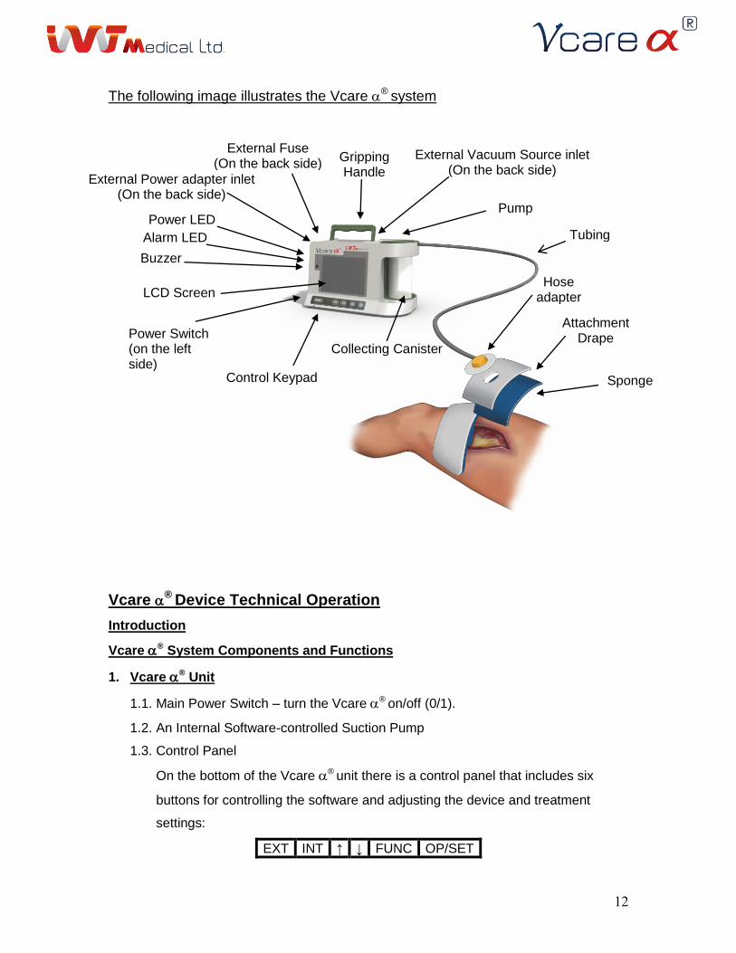
The following image illustrates the Vcare ® system
Vcare ® Device Technical Operation
Introduction
Vcare ® System Components and Functions
1. Vcare ® Unit
1.1. Main Power Switch – turn the Vcare ® on/off (0/1).
1.2. An Internal Software-controlled Suction Pump
1.3. Control Panel
On the bottom of the Vcare ® unit there is a control panel that includes six
buttons for controlling the software and adjusting the device and treatment
settings:
EXT INT ↑ ↓ FUNC OP/SET
Attachment Drape
Pump
Tubing
External Vacuum Source inlet (On the back side)
Collecting Canister
Control Keypad
Power LED Alarm LED
LCD Screen
Power Switch (on the left side)
Gripping Handle
External Power adapter inlet (On the back side)
External Fuse (On the back side)
Hose adapter
Buzzer
Sponge
13
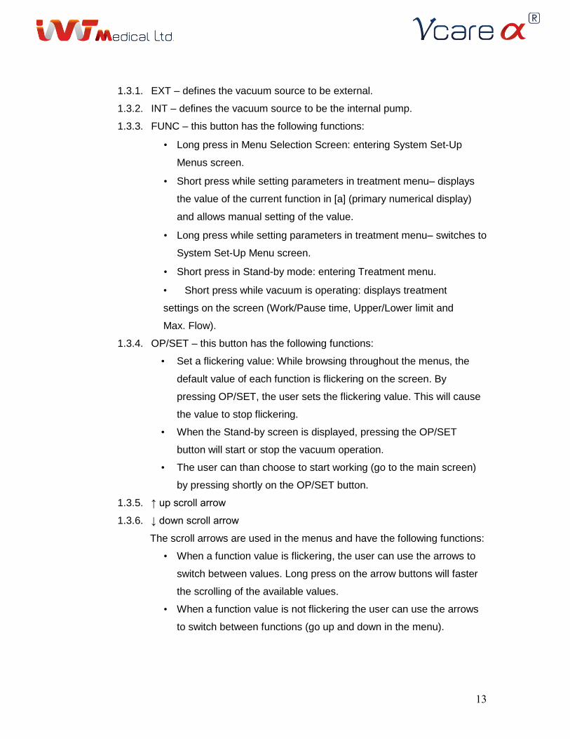
1.3.1. EXT – defines the vacuum source to be external.
1.3.2. INT – defines the vacuum source to be the internal pump.
1.3.3. FUNC – this button has the following functions:
• Long press in Menu Selection Screen: entering System Set-Up
Menus screen.
• Short press while setting parameters in treatment menu– displays
the value of the current function in [a] (primary numerical display)
and allows manual setting of the value.
• Long press while setting parameters in treatment menu– switches to
System Set-Up Menu screen.
• Short press in Stand-by mode: entering Treatment menu.
• Short press while vacuum is operating: displays treatment
settings on the screen (Work/Pause time, Upper/Lower limit and
Max. Flow).
1.3.4. OP/SET – this button has the following functions:
• Set a flickering value: While browsing throughout the menus, the
default value of each function is flickering on the screen. By
pressing OP/SET, the user sets the flickering value. This will cause
the value to stop flickering.
• When the Stand-by screen is displayed, pressing the OP/SET
button will start or stop the vacuum operation.
• The user can than choose to start working (go to the main screen)
by pressing shortly on the OP/SET button.
1.3.5. ↑ up scroll arrow
1.3.6. ↓ down scroll arrow
The scroll arrows are used in the menus and have the following functions:
• When a function value is flickering, the user can use the arrows to
switch between values. Long press on the arrow buttons will faster
the scrolling of the available values.
• When a function value is not flickering the user can use the arrows
to switch between functions (go up and down in the menu).
14
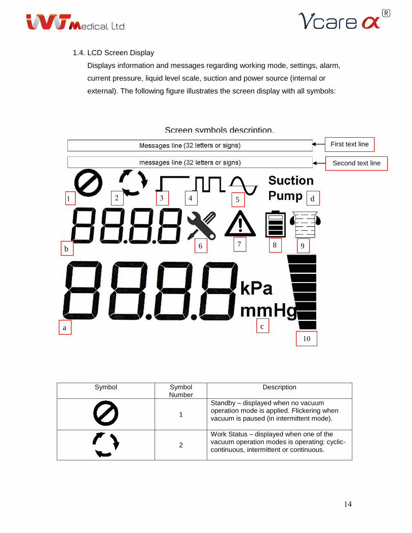
1.4. LCD Screen Display
Displays information and messages regarding working mode, settings, alarm,
current pressure, liquid level scale, suction and power source (internal or
external). The following figure illustrates the screen display with all symbols:
Screen symbols description.
Symbol Symbol Number
Description
1
Standby – displayed when no vacuum operation mode is applied. Flickering when vacuum is paused (in intermittent mode).
2
Work Status – displayed when one of the vacuum operation modes is operating: cyclic-continuous, intermittent or continuous.
1 2
1 3
1 4
1 5
1
6
1
7
1 8
1 9
1
11
b
a
c
d
First text line
Second text line
15
3
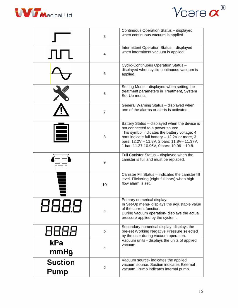
Continuous Operation Status – displayed when continuous vacuum is applied.
4
Intermittent Operation Status – displayed when intermittent vacuum is applied.
5
Cyclic-Continuous Operation Status – displayed when cyclic-continuous vacuum is applied.
6
Setting Mode – displayed when setting the treatment parameters in Treatment, System Set-Up menu.
7
General Warning Status – displayed when one of the alarms or alerts is activated.
8
Battery Status – displayed when the device is not connected to a power source. This symbol indicates the battery voltage: 4 bars indicate full battery – 12.2V or more, 3 bars: 12.2V – 11.8V, 2 bars: 11.8V– 11.37V, 1 bar: 11.37-10.96V, 0 bars: 10.96 – 10.8.
9
Full Canister Status – displayed when the canister is full and must be replaced.
10
Canister Fill Status – indicates the canister fill level. Flickering (eight full bars) when high flow alarm is set.
a
Primary numerical display: In Set-Up menu- displays the adjustable value of the current function. During vacuum operation- displays the actual pressure applied by the system.
b
Secondary numerical display: displays the pre-set Working Negative Pressure selected by the user during vacuum operation.
c
Vacuum units - displays the units of applied vacuum.
d
Vacuum source- indicates the applied vacuum source. Suction indicates External vacuum, Pump indicates internal pump.
16
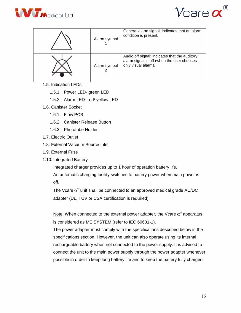
Alarm symbol 1
General alarm signal: indicates that an alarm condition is present.
Alarm symbol 2
Audio off signal: indicates that the auditory alarm signal is off (when the user chooses only visual alarm).
1.5. Indication LEDs
1.5.1. Power LED- green LED
1.5.2. Alarm LED- red/ yellow LED
1.6. Canister Socket
1.6.1. Flow PCB
1.6.2. Canister Release Button
1.6.3. Phototube Holder
1.7. Electric Outlet
1.8. External Vacuum Source Inlet
1.9. External Fuse
1.10. Integrated Battery
Integrated charger provides up to 1 hour of operation battery life.
An automatic charging facility switches to battery power when main power is
off.
The Vcare ® unit shall be connected to an approved medical grade AC/DC
adapter (UL, TUV or CSA certification is required).
Note: When connected to the external power adapter, the Vcare ® apparatus
is considered as ME SYSTEM (refer to IEC 60601-1).
The power adapter must comply with the specifications described below in the
specifications section. However, the unit can also operate using its internal
rechargeable battery when not connected to the power supply. It is advised to
connect the unit to the main power supply through the power adapter whenever
possible in order to keep long battery life and to keep the battery fully charged.
17
Warning: the external power adapter must comply with the
specifications listed in the specifications chapter in this manual.
1.11. A Gripping Handle.
1.12. External vacuum source tube.
2. Disposables
2.1. A wound discharge Collection Canister
2.2. Tubing
2.2.1. Distal Connecting Tube, a tube adapter attached to its distal end and an
Attachment drape.
2.2.2. Canister Proximal Tube.
2.3. Sponge-The Sponge consists of a basal porous layer and a covering air-tight
layer (drape).
2.4. Drape Stripes.
Note: all items in the Vcare ® system are suitable for use within the patient
environment.
Vacuum Operation Modes
The Vcare ® system can be used to apply negative pressure in the following modes:
1. Cyclic-Continuous mode – basic mode of operation. The neg. pressure oscillates
around a pre-determined value to a range of 20% of the baseline neg. pressure.
2. Intermittent mode – advanced mode of operation, allows setting and adjusting
different system parameters. When using this mode of operation, it is highly
recommended to follow the clinical guidelines for recommended vacuum pressures
and wound dressing changes provided earlier in this manual.
3. Continuous mode - advanced mode of operation, allows setting and adjusting
different system parameters. Typically used following skin transplant applications.
When using this mode of operation, it is highly recommended to follow the clinical
guidelines for recommended vacuum pressures and wound dressing changes
provided earlier in this manual.
Primary Unit Functions Setting
Positioning of the Vcare ® Unit
18
The Vcare ® unit should be placed close to the patient bed, in proximity to the external
vacuum and electricity sources. The unit should be preferably operated by direct
connection to a grounded electrical source and external vacuum source. The unit can be
placed on a stable flat dry surface or can be attached and secured to a designated
mobile stand to enable patient ambulation.
The device must be operated in a quite environment with background noise of no more
than 45-50dB.
Make sure that the external power adapter and its connecting cables are not
creating a tripping hazard.
Make sure that the ventilation holes at the back of the unit are not covered or
blocked.
If the device is connected to mobile stand there is a need to make sure that it is
securely connected to the mobile stand and that the lock-pin is closed.
The Vcare ® unit and tubing should be placed in a visible location in order to enable
direct eye contact with the system and enable early detection of bleeding and/ or
effective vacuum application to the treated area.
Collection Canister Installation
1. Insert the collection canister into the canister socket in the Vcare ® unit by pressing
it inwards. When properly inserted, a clicking sound is heard. Make sure that the
canister is placed secured and sealed in the canister socket for effective operation of
the vacuum.
2. Connect the canister proximal tube to the canister tubing outlet.
Replacing the Collection Canister
The collection canister may be replaced during normal operation, alarm condition or
routine maintenance.
The canister must be replaced when the liquid level exceeds 650 ml. In this case, an
alarm will be activated. The vacuum operation will stop when the fluids level in the
Canister reaches 700 ml.
19
When fluids in the canister reach approximately 650 ml, solidification process of the
fluids by the hydro-gel at the top of the canister will start, and will be completed within 60
minutes.
Warning: The collection canister and tubing are intended for single use only and
must be disposed off after usage according to hospital and bio-hazard protocols and
according to institutional procedures and local, state and federal environmental
regulations.
Once the fluids have solidified and reached 650 ml, follow the steps below to replace the
canister:
1. Turn off the device using the main power switch.
2. Disconnect the proximal tube from the distal tube.
3. Press the canister release button, hold the canister gently and pull it upwards in
order to take it off its socket.
4. Seal the canister through the proximal connecting tube using the tube lid.
5. Discard the canister and tubing according to the hospital and bio-hazard
protocols.
Insert a new collection canister to the socket. A clicking sound will indicate that the
canister is properly inserted.
6. Connect the new canister proximal tube to the distal tube connected to the
dressing.
7. Turn the device on using the main power switch.
8. Activate Vacuum using the OP/SET button.
9. Verify that the applied pressure displayed on the screen matches your pre-
defined setting.
Setup for Wound Dressing Application
1. Perform adequate conservative debridement of the wound to minimize bleeding prior
to dressing application.
2. Make sure that the wound area is clean.
It is possible to apply spacer in the interface between the sponge and the wound.
The spacer should serve specific conditions in RNPT treatment. To prevent
adherent of the sponge to the underlying tissue (or skin graft), a non-adherent
21
gauze should be used. Wound irrigation may be applied to the wound if
necessary. Irrigation system is not part of the Vcare ® system.
Warning: Do not place the sponge or apply vacuum over a healthy tissue. Applying
vacuum on healthy tissue may cause irritation and damage the skin.
Warning: Avoid cutting the dressing directly over the wound in order to
prevent particles from entering the wound bed.
3. Choose a suitable sponge according to the wound dimensions.
4. Choose drape stripes in a suitable length for a safe attachment of the Sponge to the
surrounding skin (the length should be determined in compliance with the Sponge
size).
5. Dry the wound edges for better sponge and drape stripes attachment.
6. Remove the taping from the drape stripes and use them to attach the sponge edges
to the wound surrounding tissue. It is recommended to cover 3-5 cm of surrounding
intact skin. Make sure that the drawing on the top of the drape is visualized (visual
regulation).
7. Choose the location to apply the distal tube and attachment drape. The location
should be at the most dependent area of the wound to prevent from accumulation of
fluids in the wound bed.
8. At this location, cut a hole through the covering layer of the sponge (the drape layer),
approximately 1-2 cm in diameter, leaving the foam layer of the mold mostly intact.
Make sure that the size of the hole is sufficient to allow fluid passage through the
drape. It is very important to cut a complete hole (rather than a slit), since a slit may
not allow fluid passage through the drape.
9. Remove the taping from the end of the distal tube and attach it to the sponge above
the hole.
10. Connect the distal tube to the canister proximal tube via the two way tube connector.
Wound Dressing Removal
Warning: The wound dressing sponge, proximal and distal connecting tubes and
attachment drape are intended for single use only and must be disposed off after usage
21
according to hospital and bio-hazard protocols and according to institutional procedures
and local, state and federal environmental regulations.
1. Turn the vacuum operation off using the OP/SET button in the control panel.
2. Turn the Vcare ® system off using the power switch.
3. Disconnect the distal tube from the proximal tube.
4. Remove the drape stripes from the surrounding of the wound.
5. Remove the sponge from the wound bed.
6. Make sure that the entire sponge has been removed.
Positioning of the Vcare ® Unit on the Mobile Stand
1. Hold the Vcare with one hand by its carrying handle when its LCD screen
faced toward the front of the mobile stand.
2. Slide the Vcare by its external plate on the shelf track that placed on the
upper side of the mobile stand.
3. Pull the pin-lock until the external plate is properly inserted into the shelf track.
4. In order to complete its positioning, release the pin lock and continue sliding the
external plate until the external plate is locked by the pin lock (a clicking sound
needed to be heard).
Vcare ® Termination of Operation
1. Turn the vacuum operation off using the OP/SET button in the control panel.
2. Turn the Vcare ® system off using the power switch.
Vcare ® Operation
Before operating the Vcare ®, verify that:
• The Vcare ® is placed on a suitable surface according to Positioning the Vcare ®
unit section in this manual.
• The collection canister is properly installed according to Disposable canister
installation section in this manual.
• The wound dressing is properly applied according to Setup for wound dressing
application section in this manual.
22
• When connecting the Vcare ® to its mobile stand make sure it is properly
connected according a clicking sound is heard.
1. Use a suitable external power adapter to connect the Vcare ® unit (via the electric
receptacle) to the wall electrical outlet.
When connecting the unit to the external power adapter, the operator should be
facing the back of the device, in front of the power electrical outlet.
Warning: The External power adapter must follow the specifications detailed
in the External power adapter specifications section in this manual.
Warning: Do not connect the unit to a damaged external power adapter.
Note: In order to work in Battery mode, make sure that power adapter is not
connected.
Warning: The internal battery is not accessible for users. In case that battery
malfunction is suspected during warrantee period, contact IVT Medical Ltd.
The Power indication LED is lit.
2. Turn the Vcare ® unit on using its power switch button located on the left side of the
unit.
When turning the device on, the operator should face the power switch on the left
side of the device.
During treatment parameter settings and vacuum operation, the operator should
face the front side of the Vcare ® unit (in front of the screen and control panel).
3. Main screens
3.1. Opening Screen
As the unit is turned on, an opening screen is displayed for approximately 10
seconds. The first line displays the caption IVT Medical Ltd. and the second line
displays Vcare Alpha.
3.2. Self test screen
Following the Opening screen, the LCD screen is being self-tested for a few
seconds (this self-test is performed every time the unit is turned on). During the self-
testing phase, the display shows "TEST LCD", symbols 1-10 are displayed on the
23
screen, digits in [a] and [b] vary from 0 through 9, bars in symbol no. 10 fill gradually
and the buzzer produces a short beeping sound.
3.3. Menu selection screen
After the LCD self test screen is displayed, the user will have two options for setting
the treatment’s parameters: pressing ↓ for treatment menu, in which basic treatment
parameters are set, or pressing FUNC for approximately 5 seconds in order to enter
the advanced set-up menu (for detailed information about the menus, go to the
menus chapter).
3.4. Stand-by screen
This screen is displayed after setting the treatment parameters and before starting
the vacuum operation. The caption Stand-by is displayed in the first line. Pre-set
neg. working pressure is displayed in [b], pressure units are displayed in [c], vacuum
source is displayed in [d], and symbol no. 1 is displayed on the screen. The user is
instructed to press OP/SET to start the vacuum operation.
3.5. Working mode screen
As the user starts the vacuum operation, the working mode screen is displayed
during treatment. The working mode screen displays the pre-set working neg.
pressure in [b], the actual pressure applied to the wound in [a], the pressure units in
[c], the vacuum source in [d], along with symbol no. 2.
As the vacuum pauses when working in intermittent or cyclic-continuous mode,
symbol no. 1 is flickering on the screen as an indication.
4. Vacuum Applying Mode Determination
The button INT/EXT allows the user to choose the desired vacuum source:
4.1. Internal Suction Mode (Pump)
In order to work with the device's internal suction apparatus press INT button.
4.2. External Suction Mode
Press EXT button in order to work with external vacuum source. This requires
connection to the external source using the external vacuum source tube.
For continuous mode of operation use an external vacuum source. The device
cannot operate in continuous mode (and will not allow choosing 0 minutes pause
time) when operating under internal suction mode.
24
For cyclic-continuous mode, it is recommended to use external vacuum source.
When using the internal pump in cyclic continuous mode, the pump will pause for 1
minute every 10 minutes of operation. All other settings will operate in the same way
for both external and internal suction modes.
5. Menus
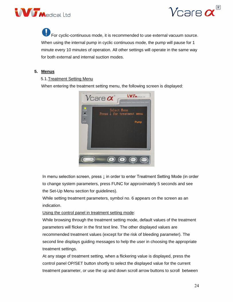
5.1. Treatment Setting Menu
When entering the treatment setting menu, the following screen is displayed:
In menu selection screen, press ↓ in order to enter Treatment Setting Mode (in order
to change system parameters, press FUNC for approximately 5 seconds and see
the Set-Up Menu section for guidelines).
While setting treatment parameters, symbol no. 6 appears on the screen as an
indication.
Using the control panel in treatment setting mode:
While browsing through the treatment setting mode, default values of the treatment
parameters will flicker in the first text line. The other displayed values are
recommended treatment values (except for the risk of bleeding parameter). The
second line displays guiding messages to help the user in choosing the appropriate
treatment settings.
At any stage of treatment setting, when a flickering value is displayed, press the
control panel OP/SET button shortly to select the displayed value for the current
treatment parameter, or use the up and down scroll arrow buttons to scroll between
25
available values for the current parameter and then press OP/SET to select the
required value.
After pressing OP/SET, the displayed value will stop flickering.
When the value is not flickering, use the up and down scroll arrow buttons to scroll
between treatment parameters.
At certain treatment setting functions, pressing FUNC shortly allows advanced
treatment settings. In this mode, the default value is displayed in [a], and by using
the up and down scroll arrow buttons the value can be changed in a pre-set range.
At any stage of the treatment setting mode, holding the FUNC button for
approximately 5 seconds allows switching to Set-Up Menu.
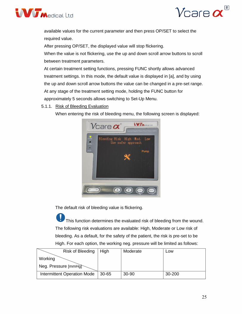
5.1.1. Risk of Bleeding Evaluation
When entering the risk of bleeding menu, the following screen is displayed:
The default risk of bleeding value is flickering.
This function determines the evaluated risk of bleeding from the wound.
The following risk evaluations are available: High, Moderate or Low risk of
bleeding. As a default, for the safety of the patient, the risk is pre-set to be
High. For each option, the working neg. pressure will be limited as follows:
Risk of Bleeding
Working
Neg. Pressure [mmHg]
High Moderate Low
Intermittent Operation Mode 30-65 30-90 30-200
26
Cyclic-Cont. Operation Mode 40 / 50 40 / 50 / 75 40 / 50 / 75 / 100 /
125
As the Risk of Bleeding is set to High or Moderate, for the safety of the
treatment, Max Flow and Alarms will be limited to the default values of 100
ml/hr and Audio & Visual, respectively.
Use the up and down scroll arrow buttons in the control panel to change the
flickering value and determine the evaluated Risk of Bleeding.
Press the OP/SET button to finalize your selection. The value stops flickering.
Press ↓ to continue to the next parameter.
Warning: Consider carefully any change from the default settings.
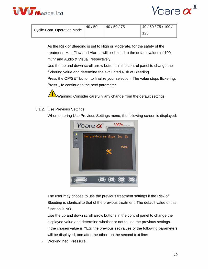
5.1.2. Use Previous Settings
When entering Use Previous Settings menu, the following screen is displayed:
The user may choose to use the previous treatment settings if the Risk of
Bleeding is identical to that of the previous treatment. The default value of this
function is NO.
Use the up and down scroll arrow buttons in the control panel to change the
displayed value and determine whether or not to use the previous settings.
If the chosen value is YES, the previous set values of the following parameters
will be displayed, one after the other, on the second text line:
• Working neg. Pressure.
27
• Upper / Lower Limit.
• Max. Flow.
• Work / Pause Time (displayed only if the previous Mode of Operation is
Intermittent).
After viewing the previous settings, the following options are available:
• Press ↓ to go to Stand-by screen.
• Press FUNC to adjust treatment settings.
Pressing FUNC will transfer the user to the next function in the menu. In this
case, the flickering values will be the values chosen in the previous treatment,
and the user will be able to change them.
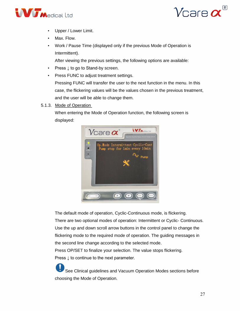
5.1.3. Mode of Operation
When entering the Mode of Operation function, the following screen is
displayed:
The default mode of operation, Cyclic-Continuous mode, is flickering.
There are two optional modes of operation: Intermittent or Cyclic- Continuous.
Use the up and down scroll arrow buttons in the control panel to change the
flickering mode to the required mode of operation. The guiding messages in
the second line change according to the selected mode.
Press OP/SET to finalize your selection. The value stops flickering.
Press ↓ to continue to the next parameter.
See Clinical guidelines and Vacuum Operation Modes sections before
choosing the Mode of Operation.
28
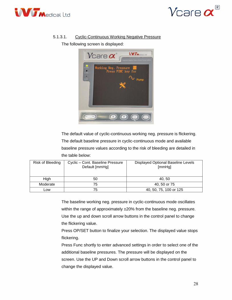
5.1.3.1. Cyclic-Continuous Working Negative Pressure
The following screen is displayed:
The default value of cyclic-continuous working neg. pressure is flickering.
The default baseline pressure in cyclic-continuous mode and available
baseline pressure values according to the risk of bleeding are detailed in
the table below:
Risk of Bleeding Cyclic – Cont. Baseline Pressure Default [mmHg]
Displayed Optional Baseline Levels [mmHg]
High 50 40, 50
Moderate 75 40, 50 or 75
Low 75 40, 50, 75, 100 or 125
The baseline working neg. pressure in cyclic-continuous mode oscillates
within the range of approximately ±20% from the baseline neg. pressure.
Use the up and down scroll arrow buttons in the control panel to change
the flickering value.
Press OP/SET button to finalize your selection. The displayed value stops
flickering.
Press Func shortly to enter advanced settings in order to select one of the
additional baseline pressures. The pressure will be displayed on the
screen. Use the UP and Down scroll arrow buttons in the control panel to
change the displayed value.
29
Press OP/SET button to finalize your selection. The value stops flickering.
It is recommended to use external vacuum source as possible.
When using the internal pump in cyclic continuous mode, the
pump will pause for 1 minute every 10 minutes of operation.
Following the determination of the Cyclic-Continuous base- line
working neg. pressure, pressing ↓ will switch to the last function in
this menu: Start Working. Pressing the OP/SET button will transfer
the user to the stand-by screen (see Main screens chapter).
5.1.3.2. Intermittent / Continuous Mode
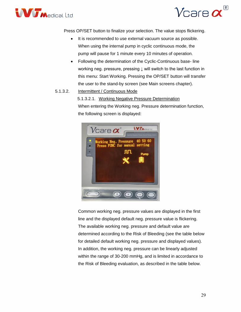
5.1.3.2.1. Working Negative Pressure Determination
When entering the Working neg. Pressure determination function,
the following screen is displayed:
Common working neg. pressure values are displayed in the first
line and the displayed default neg. pressure value is flickering.
The available working neg. pressure and default value are
determined according to the Risk of Bleeding (see the table below
for detailed default working neg. pressure and displayed values).
In addition, the working neg. pressure can be linearly adjusted
within the range of 30-200 mmHg, and is limited in accordance to
the Risk of Bleeding evaluation, as described in the table below.
31
Risk for Bleeding Default Working Pressure [mmHg]
Displayed Pressure Values [mmHg]
Working Pressure Range [mmHg]
High 60 40, 50, 60 30-65
Moderate 70 60, 70, 80 30-90
Low 80 60, 80, 100 No limit (30-200)
Use the up and down scroll arrow buttons in the control panel to
change the flickering value and determine the required Working
neg. Pressure.
Press OP/SET to finalize your selection. The value stops
flickering.
For advanced pressure setting, press FUNC shortly. The working
neg. pressure value will be displayed in [a].
Use the up and down scroll arrow buttons in the control panel to
change the displayed value and determine the required Working
neg. Pressure. Press OP/SET to finalize your selection. The
displayed value stops flickering.
Press ↓ to continue to the next parameter.
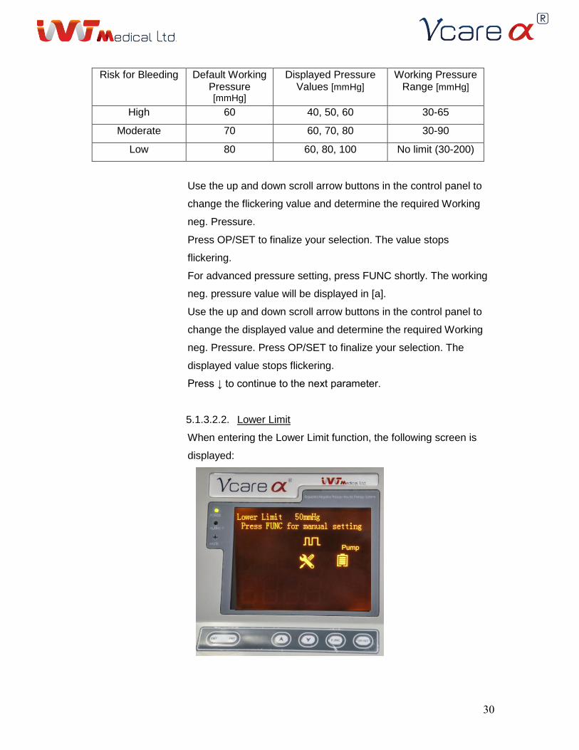
5.1.3.2.2. Lower Limit
When entering the Lower Limit function, the following screen is
displayed:
31
The default lower limit value is flickering.
The default value of the lower limit is pre-set to be 10 mmHg
below the working neg. pressure and the range of the lower limit
can be linearly adjusted within the range of 30 mmHg to the
default value.
For advanced Lower Limit settings, press FUNC shortly. This
allows the user to change the Lower Limit to a different value in
the pre-set available range. Use the up and down scroll arrow
buttons in the control panel to change the displayed value and
determine the required lower limit.
Press OP/SET button to finalize your selection. The displayed
value stops flickering.
Press ↓ to continue to the next parameter.
Warning: do not set low values of lower limit in order for the
system to detect improper vacuum applied to the wound.
In case the pressure applied by the device will be lower than the
lower limit value, an alert will be generated (see the Alarms
chapter for more details).
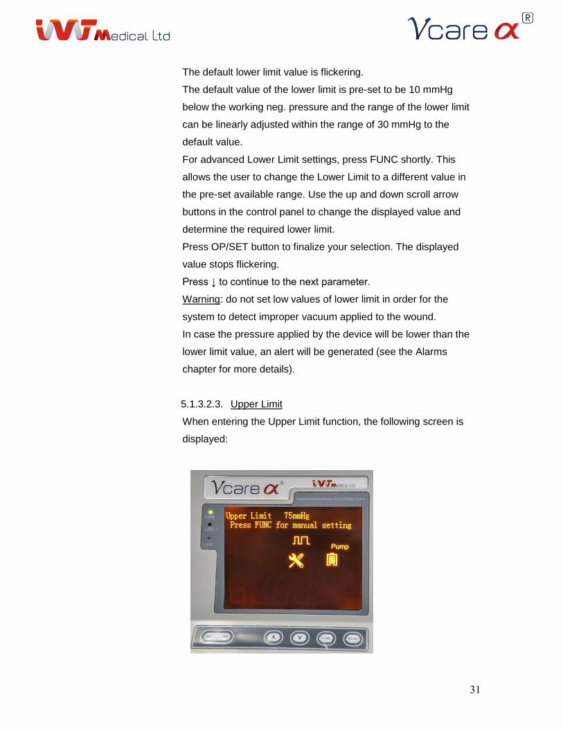
5.1.3.2.3. Upper Limit
When entering the Upper Limit function, the following screen is
displayed:
32
The default upper limit value is flickering.
The default value of the upper limit is pre-set to be 15 mmHg
above the working neg. pressure and the range of the allowed
upper limit is pre-set according to the Risk of Bleeding and
Working neg. Pressure (WP) selection as follows:
Risk of Bleeding Upper Limit Range
High WP+15 to 80
Moderate WP+15 to 105
Low WP+15 to 215
For advanced Upper Limit settings, press FUNC shortly. This
allows the user to change the Upper Limit to a different value in
the pre-set available range.
The upper limit is displayed in [a].
Use the up and down scroll arrow buttons in the control panel to
change the displayed value and determine the required upper
limit.
Press OP/SET button to finalize your selection. The displayed
value stops flickering.
Press ↓ to continue to the next parameter.
Warning: do not set high values of upper limit in order for
the system to detect improper vacuum applied to the wound.
In case the vacuum applied by the device will be higher than
the upper limit value, an alert will be generated (see Alarms
chapter for more details).
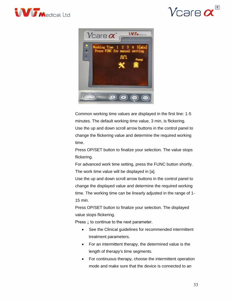
5.1.3.2.4. Working Time Determination
When entering the Working Time determination function, the
following screen is displayed:
33
Common working time values are displayed in the first line: 1-5
minutes. The default working time value, 3 min, is flickering.
Use the up and down scroll arrow buttons in the control panel to
change the flickering value and determine the required working
time.
Press OP/SET button to finalize your selection. The value stops
flickering.
For advanced work time setting, press the FUNC button shortly.
The work time value will be displayed in [a].
Use the up and down scroll arrow buttons in the control panel to
change the displayed value and determine the required working
time. The working time can be linearly adjusted in the range of 1-
15 min.
Press OP/SET button to finalize your selection. The displayed
value stops flickering.
Press ↓ to continue to the next parameter.
See the Clinical guidelines for recommended intermittent
treatment parameters.
For an intermittent therapy, the determined value is the
length of therapy's time segments.
For continuous therapy, choose the intermittent operation
mode and make sure that the device is connected to an
34
external vacuum source. This will enable the user to set
the pause time value to zero.
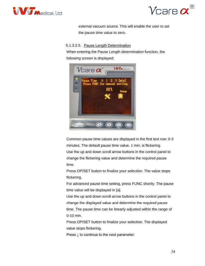
5.1.3.2.5. Pause Length Determination
When entering the Pause Length determination function, the
following screen is displayed:
Common pause time values are displayed in the first text row: 0-3
minutes. The default pause time value, 1 min, is flickering.
Use the up and down scroll arrow buttons in the control panel to
change the flickering value and determine the required pause
time.
Press OP/SET button to finalize your selection. The value stops
flickering.
For advanced pause time setting, press FUNC shortly. The pause
time value will be displayed in [a].
Use the up and down scroll arrow buttons in the control panel to
change the displayed value and determine the required pause
time. The pause time can be linearly adjusted within the range of
0-10 min.
Press OP/SET button to finalize your selection. The displayed
value stops flickering.
Press ↓ to continue to the next parameter.
35
For continuous therapy, make sure that the device is
connected to an external vacuum source. This will enable the user
to set the pause time value to zero. The device cannot operate on
continuous mode when using the internal pump.
Warning: Avoid long pause of the vacuum. As the Vcare ®
is operating, fluids are discharged and constantly evacuated from
the wound. Once the vacuum is halted, the system is at risk
of becoming occlusive, which might lead to infection.
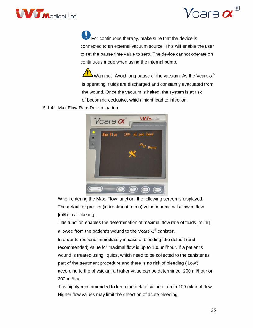
5.1.4. Max Flow Rate Determination
When entering the Max. Flow function, the following screen is displayed:
The default or pre-set (in treatment menu) value of maximal allowed flow
[ml/hr] is flickering.
This function enables the determination of maximal flow rate of fluids [ml/hr]
allowed from the patient's wound to the Vcare ® canister.
In order to respond immediately in case of bleeding, the default (and
recommended) value for maximal flow is up to 100 ml/hour. If a patient's
wound is treated using liquids, which need to be collected to the canister as
part of the treatment procedure and there is no risk of bleeding ('Low')
according to the physician, a higher value can be determined: 200 ml/hour or
300 ml/hour.
It is highly recommended to keep the default value of up to 100 ml/hr of flow.
Higher flow values may limit the detection of acute bleeding.
36
Use the up and down scroll arrow buttons to change the flickering value and
determine the maximal allowed flow from the wound to the canister.
Press OP/SET to finalize your selection. The value stops flickering.
Press FUNC to continue to the next function.
For the safety of the patient, if you have previously evaluated the Risk of
Bleeding as High or Moderate, you will not be able to change the Max Flow to
be higher than 100 ml/hr.
In case the accumulated fluid volume in the canister exceeds the
maximal volume allowed during operation, an alarm will be activated and the
vacuum operation will be shut down (see the Alarms and Alerts chapter for
more details).
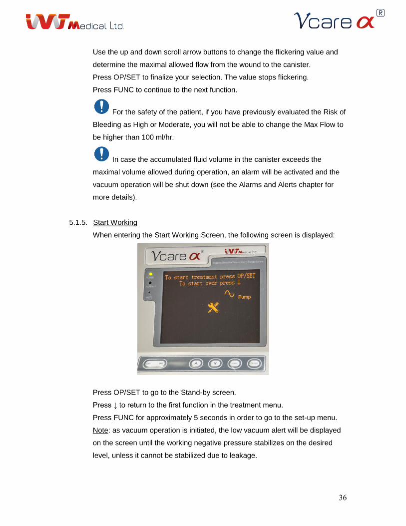
5.1.5. Start Working
When entering the Start Working Screen, the following screen is displayed:
Press OP/SET to go to the Stand-by screen.
Press ↓ to return to the first function in the treatment menu.
Press FUNC for approximately 5 seconds in order to go to the set-up menu.
Note: as vacuum operation is initiated, the low vacuum alert will be displayed
on the screen until the working negative pressure stabilizes on the desired
level, unless it cannot be stabilized due to leakage.
37
5.2. System Set-Up Menu
In menu selection screen, press FUNC for approximately 5 seconds in order to enter
System Set-Up Screen. While setting treatment parameters, symbol no. 6 appears
on the screen as an indication.
Using the control panel in system set-up menu:
At any stage of system set-up, when a flickering value is displayed, press shortly on
the control panel OP/SET button in order to select the displayed value for the current
treatment parameter, or, use the up and down scroll arrow buttons to brows between
available values for the current parameter and then press OP/SET button to select
the required value.
After pressing OP/SET, the displayed value will stop flickering.
When the value is not flickering, press the Down Scroll arrow button shortly in order
to continue to the next function.
At any stage of the system set-up menu, pressing the FUNC button for
approximately 5 seconds will switch to the Stand-By screen. The user can then
choose to start the vacuum operation by pressing OP/SET.
5.2.1. F1: Language
The language function displays the current language used for user interface in
the Vcare ® unit.
Press the Down Scroll button in order to continue to the next function.
5.2.2. F2: Alarm Mode Determination
The displayed default alarm mode, Audio and Visual alarms (A&V), is
flickering.
Use the up and down scroll arrow buttons in the control panel to change the
flickering value and select the desired alarm mode:
5.2.2.1. Visual (Visual alarm only)
The alarms indication will be only visual (flickering indication light and
general alarm symbol). A relevant message will be displayed on the
screen.
5.2.2.2. A&V (Audio and Visual alarms)
In any case which necessitates alarm generation, the indication will
be both auditory (A repetitive beeping sound) and visual (flickering
38
indication light and general alarm symbol) along with a relevant
message.
In order to monitor the wound healing and treatment process, it is
important for the care-giver to be aware to all alarms and indications
regarding the suction apparatus and treatment. Therefore, it is advised to
keep the default alarm setting, which is an audio and visual alarm. Any
change of alarms setting may prevent from the care-giver the detection of
critical indications regarding the vacuum treatment and may lead to
misuse of the suction apparatus.
For the safety of the patient, if you have previously evaluated the
Risk for Bleeding as High or Moderate, you will not be able to change the
Alarms from the default setting (Audio & Alarms).
Press OP/SET button to finalize your selection. The value stops flickering.
Press Down Scroll arrow in order to continue to the next function.
For more information regarding alarms types and operation, see the
alarms chapter.
5.2.3. F3: Negative Pressure Units Determination
The default pressure units setting, mmHg, is flickering in the first text line.
Use the up and down scroll arrow buttons in the control panel to change the
flickering value and determine the systems pressure units: mmHg or KPa.
Press OP/SET to finalize your selection. The value stops flickering.
Press Down Scroll arrow to continue to the next function.
5.2.4. F4: Battery Voltage Display
The current battery voltage (in volts) is displayed on the screen.
Press Down Scroll arrow in order to continue to the next function.
5.2.5. F5: Total Pump Operation Time Display
The total working hours of the engine are displayed on the screen.
Press Down Scroll arrow in order to continue to the next function.
39
5.2.6. F6: Software Version Display
The current version of the system software is displayed on the screen.
Press the Down Scroll button in order to continue to the next function.
5.2.7. F7: Back Screen
5.2.7.1. Incase reaching from treatment menu. First line: "To Treatment menu
press OP/SET" – returning to the last screen we had been in the
treatment menu, before reaching the set-up menu.
Second line: "To start over press FUNC" – start over the set-up
menu.
5.2.7.2. Incase reaching from Stand-By screen (after setting all parameters in
the treatment menu)
First line: "To start treatment press OP/SET" – returning to the "stand-
by screen".
Second line: "To start over press FUNC" – start over the set-up menu
5.2.7.3. Incase reaching from Stand-By screen (after yes was chosen at "use
previous setting" screen)
First line: "To Treatment menu press OP/SET" returning to the risk of
bleeding screen.
Second line: "To start over press FUNC" – start over the set-up menu
Note: as vacuum operation is initiated, the low vacuum alert will be displayed
on the screen until the working negative pressure stabilizes on the desired
level, unless it cannot be stabilized due to leakage.
Vcֹare ® quick instructions guide
1. Verify that the wound doesn't actively bleed.
2. Insert the collection canister into the canister socket sound….
3. Connect the canister proximal tube to the collection canister.
4. When using mobile stand, make sure the Vcare ® unit is securely
connected to the mobile stand and that the lock-pin is closed.
5. Connect the Vcare ® unit using a suitable power adapter (see specifications
chapter) to the wall electrical outlet.
6. Turn the Vcare ® unit on.
7. Select External/Internal vacuum source (it is advised to use external vacuum source
as possible to avoid burnout of the internal pump).
8. Set the treatment parameters using the Treatment Setting Menu section.
41
9. Apply wound dressing to the wound (see "Setup for dressing application" for detailed
instructions).
10. Connect the canister proximal tube to the distal connecting tube via the two way tube
connector.
11. Activate vacuum using the OP/SET button on the control panel.
12. Verify that the wound dressing is sealed (inspect the sponge to be evenly
condensed/squeezed.).
13. Check the display and verify that the neg. pressure applied is according to the pre-
set value (a minor fluctuation of +/-5 mmHg in actual pressure should be expected).
14. Patient and wound status should be monitored regularly according to the clinical
condition of the wound.
When the device is operated by the internal battery, operation of
approximately 1 hour is expected.
Alarms and Alerts
Vcare ® Alarm system
The Vcare ® system has two kinds of alarm signals:
o Visual alarm- consists of an indication LED (red/ yellow) and of the following alarm
condition symbol: (Alarm sumbol no. 1 from the symbols description table).
o Auditory alarm- repetitive beeping sound produced by a buzzer. The beeping
frequencies and inter-burst intervals change according to alarm condition priority
(High and Low) in order for the care-giver to identify the priority of the alarm condition
from distance and act accordingly.
In order to hear the auditory alarm the device must be operated in a quite
environment with background noise of no more than 45-50dB.
For further information, see buzzer specification in the specifications section.
The user is able to choose between a visual alarm and a visual & auditory alarm signals.
1. Alarm conditions
41
1.1. Critical battery alarm
Description: this alarm is initiated when battery voltage is too low to support
operation of the system. In this case, vacuum operation is shut down and alarms are
set.
Priority: High.
Visual alarm signal: flickering red indication LED, alarm signal no. 1- general alarm
signal from screen symbols description table.
Auditory alarm signal: high frequency repetitive beeping sound.
Additional signals: general warning status (symbol no. 7), low battery status (symbol
no. 8 with no black bars) from screen symbols description table.
Information sentences: First line: “Critical Battery Condition”, Second line: "Connect
to main source”.
To resolve this alarm: connect the Vcare ® unit to the wall outlet using a suitable
external power adapter (see specifications section) and press OP/SET to resume
treatment.
Battery malfunction is expected if the system is not connected to an external power
adapter immediately.
In case this alarm is repeated after following these instructions, contact your service
provider.
1.2. High flow alarm
Description: this alarm is initiated when the system detects that the accumulated
liquids volume in the collection canister exceeds the pre-defined maximal volume per
hour.
In this case, vacuum operation is automatically shut down and alarms are set.
High flow stops the vacuum operation.
It will not be possible to re-activate the device by pressing the OP/SET button.
For re-operation, the device will have to be re-started.
Priority: High.
Visual alarm signal: flickering red indication LED, alarm signal no. 1- general alarm
signal from screen symbols description table.
Auditory alarm signal: high frequency repetitive beeping sound.
42
Additional signals: general warning status (symbol no. 7) from screen symbols
description table.
Information sentences: First line: “Watch for possible bleeding”, Second line: “Turn
off for reactivation”.
To resolve this alarm
• Turn the Vcare ® unit off.
• A physician must inspect the patient to find if there is active bleeding from the
wound.
• Therapy should not be re-activated before an extensive physician inspection and
re-evaluation of active bleeding and the risk of bleeding from the wound.
• If there are still signs for bleeding, apply compressive pressure on the wound and
evaluate the need for further intervention.
In case this alarm is repeated after following these instructions, contact your service
provider.
1.3. Extreme High Vacuum alarm
Description: this alarm is initiated when the applied neg. pressure is:
• 20 mmHg above upper limit for 30 seconds or;
• Above the upper limit but below upper limit + 20 mmHg for 1 more minute (meaning 1.5 minutes from the high vacuum alert activation).
In this case, vacuum operation is automatically shut down.
Priority: High.
Visual alarm signal: flickering red indication LED, alarm signal no. 1- general alarm
signal from screen symbols description table.
Auditory alarm signal: high frequency repetitive beeping sound.
Additional signals: general warning status (symbol no. 7) from screen symbols
description table.
Information sentences: First line: “Hazardous operation level”, Second line: (1)
“Caution!” (2) “Extreme high op. zone!” (3) “Turn off for re-activation” (where (1), (2)
and (3) are presented one after the other for 5 seconds each).
To resolve this alarm:
• Turn the Vcare ® unit off.
43
• In case an external vacuum source is connected, reduce the pressure from the
external vacuum source to ~10 mmHg above the working negative pressure
level. If not;
• Restart the device.
In case this alarm is repeated after following these instructions, contact your service
provider.
In order to confirm that the preset vacuum is actually applied to the wound, it is
recommended that together with the treatment operational setting, the care-provider
should inspect the sponge to be evenly condensed/ squeezed.
1.4. High Vacuum alarm
Description: The applied neg. pressure is above the upper limit but does not exceed
upper limit + 20 mmHg, for continuously 30 seconds.
Priority: Low.
Visual alarm signal: constant yellow indication LED, alarm signal no. 1- general
alarm signal from screen symbols description table.
Auditory alarm signal: low frequency repetitive beeping sound.
Additional signals: general warning status (symbol no. 7) from screen symbols
description table.
Information sentences: First line: “Caution! High level vacuum”. If connected to
external suction, the Second line displays: (1) “Reduce external suction” (2) “to
Working Pressure” (where (1) and (2) are presented one after the other for 5
seconds each).
To resolve this alarm:
• Stop the vacuum operation.
• Turn the Vcare ® unit off.
• In case an external vacuum source is connected, reduce the pressure from the
external vacuum source to ~10 mmHg above the working negative pressure
level. If not;
• Restart the device.
In case this alarm is repeated after following these instructions, contact your service
provider.
44
In order to confirm that the preset vacuum is actually applied to the wound, it is
recommended that together with the treatment operational setting, the care-provider
should inspect the sponge to be evenly condensed/ squeezed.
Warning: failure to respond to this alarm may lead to tissue damage. If not resolved immediately, high vacuum condition would eventually turn to Extreme
High Vacuum condition.
1.5. Low Vacuum alarm
Description: The applied neg. pressure is less than 25 mmHg from the lower limit for
continuously 30 seconds.
Priority: Low.
Visual alarm signal: constant yellow indication LED, alarm signal no. 1- general
alarm signal from screen symbols description table.
Auditory alarm signal: low frequency repetitive beeping sound.
Additional signals: general warning status (symbol no. 7) from screen symbols
description table.
Information sentences: First line: “Ineffective vacuum level”.
To resolve this alarm:
• Inspect the sponge, drape stripes, tubing and collection canister for possible
leakage.
• Make sure that the canister is positioned properly in the canister socket.
• If connected to an external vacuum source, make sure that the pressure from
the external vacuum source is above the working pressure.
• In case the applied vacuum is ~0 mmHg but the pump is working, contact your
service provider for hydro-gel filter inspection.
In case this alarm is repeated after following these instructions, contact your service
provider.
Warning: Do not leave a wound covered without effective vacuum for long time
periods.
Warning: failure to respond to this alarm may exacerbate wound infection.
45
If not resolved immediately, low pressure condition may eventually turn to Extreme
low pressure condition.
1.6. Extreme Low Vacuum alarm
Description: the applied neg. pressure is less than 25 mmHg for continuously 15
minutes.
Priority: Low.
Visual alarm signal: constant yellow indication LED, alarm signal no. 1- general
alarm signal from screen symbols description table.
Auditory alarm signal: low frequency repetitive beeping sound.
Additional signals: general warning status (symbol no. 7) from screen symbols
description table.
Information sentences: First line: “Ineffective vacuum level”, Second line: (1) “Check
for leakage” (2) “and tubing connectivity” (where (1) and (2) are presented one after
the other for 5 seconds each).
To resolve this alarm:
• Inspect the sponge, drape strips, tubing and collection canister for possible
leakage.
• Make sure that the canister is positioned properly in the canister socket.
• If connected to an external vacuum source, make sure that the pressure from
the external vacuum source is above the working pressure.
• In case the applied vacuum is ~0 mmHg but the pump is working, contact your
service provider for hydro-gel filter inspection.
In case this alarm is repeated after following these instructions, contact your service
provider.
Warning: Do not leave a wound covered without effective vacuum for long time
periods.
Warning: failure to respond to this alarm may exacerbate wound infection.
1.7. Low Battery alarm
46
Description: this alarm is initiated when battery voltage is low and approximately 10
minutes of operation are left.
Priority: Low.
Visual alarm signal: constant yellow indication LED, alarm signal no. 1- general
alarm signal from screen symbols description table.
Auditory alarm signal: low frequency repetitive beeping sound.
Additional signals: general warning status (symbol no. 7), low battery status (symbol
no. 8 with 1 black bar) from screen symbols description table.
Information sentences: First line: “Low battery”, Second line: “connect to main
source”.
To resolve this alarm: connect the Vcare ® unit to the wall outlet using a suitable
external power adapter (see specifications section).
In case this alarm is repeated after following these instructions, contact your service
provider.
Warning: Do not leave a wound covered without effective vacuum for long time
periods.
To avoid battery malfunction, connect the system to an external power adapter
immediately.
Warning: this device should be operated with a power adapter which complies
with the specifications detailed in the external power adapter specifications section.
Warning: The internal battery is not accessible for users. In case that battery
malfunction is suspected, Contact IVT Medical Ltd. for a certified technical
personnel.
If not resolved immediately, low battery condition would eventually turn to Critical
battery condition.
1.8. Near Full Canister alarm
Description: The liquid volume in the collection canister is 650 ml.
Priority: Low.
Visual alarm signal: constant yellow indication LED, alarm signal no. 1- general
alarm signal from screen symbols description table.
Auditory alarm signal: low frequency repetitive beeping sound.
47
Additional signals: general warning status (symbol no. 7) and canister fill status-
indicates the canister fill level (symbol no. 10) from screen symbols description table.
Information sentences: First line: “Canister near full capacity”.
1.9. Full Canister alarm
Description: As the liquid volume reaches 700 ml, vacuum operation is automatically
shut down.
Priority: Low.
Visual alarm signal: constant yellow indication LED, alarm signal no. 1- general alarm
signal from screen symbols description table.
Auditory alarm signal: low frequency repetitive beeping sound.
Additional signals: general warning status (symbol no. 7) and canister fill status-
indicates the canister fill level (symbol no. 10) from screen symbols description table.
Information sentences: First line: “Full canister”, Second line” (1) “Turn system off (2)
replace canister and” (3) “Re-activate treatment” (where (1), (2) and (3) are presented
one after the other for 5 seconds each).
Additional signal: symbol number 9 appears on the screen.
To resolve this alarm:
• Stop the vacuum operation.
• Turn the Vcare ® unit off.
• Replace the collection canister as instructed in replacing the collection canister
section in this manual.
• Restart the device.
In case this alarm is repeated after following these instructions, contact your service
provider.
Vacuum operation stops automatically when the fluids level in the canister is 700 ml.
In case this alarm is repeated, contact your service provider.
For further information regarding the alarm system, please refer to the alarm appendix.
In case of mechanical or electronic failure of the device and for any query or
improvement suggestion contact your service provider.
2. Alert conditions
2.1. High Vacuum alert
48
Description: the applied neg. pressure is above the upper limit.
Alarm signals: none.
Additional signals: general warning status (symbol no. 7) from screen symbols
description table.
Information sentences: Second line: (1)”Caution: Pressure is” (2) “above upper limit”
(where (1) and (2) are presented one after the other for 5 seconds each).
To resolve this alert:
• Stop the vacuum operation.
• Turn the Vcare ® unit off.
• If connected to an external vacuum source, reduce the pressure from it
• Restart the device.
In case this alarm is repeated after following these instructions, contact your service
provider.
In order to confirm that the preset vacuum is actually applied to the wound, it is
recommended that together with the treatment operational setting, the care provider
should inspect the sponge to be evenly condensed/ squeezed.
Warning: failure to respond to this alert may lead to High Vacuum alarm
condition.
2.2. Low Vacuum alert
Description: the applied neg. pressure is below the lower limit.
Note: as vacuum operation is initiated, the low vacuum alert will be displayed on the
screen until the working negative pressure stabilizes on the desired level, unless it
cannot be stabilized due to leakage.
Alarm signals: none.
Additional signals: general warning status (symbol no. 7) from screen symbols
description table.
Information sentences: Second line: (1)”Caution: Pressure is” (2) “below lower limit”.
To resolve this alert:
• Inspect the sponge, drape stripes, tubing and collection canister for possible
leakage.
• Make sure that the canister is positioned properly in the canister socket.
49
• Make sure that the pressure from the external vacuum source is above the
working pressure.
In case this alarm is repeated after following these instructions, contact your service
provider.
Warning: failure to respond to this alert may lead to Low pressure alarm
condition.
3. Maintenance and Error alerts
The maintenance and error alerts are displayed, when necessary, following the self
test screen. The user can choose to postpone the alert to a later stage (Postpone)
or to resolve it immediately (Done) by using the scroll arrow buttons and finalizing
the selection by pressing the OP/SET button. The user needs to follow the
instruction in user manual section 3.1-3.3. Only after conducting all the required
procedures the user need to press the "Done" button. The default selection of this
alert is “Postpone”.
3.1. Device Service and Maintenance
Description: in order to maintain the device performance and effective operation, the
Vcare ® unit should go through routine maintenance inspection. Routine
maintenance is required after 5000 hours or following one year of engine operation
(whichever comes first).
Alarm signals: none.
Additional signals: general warning status (symbol no. 7) from screen symbols
description table (the signals will appear only after 4500 hours of operation).
Information sentences: First line: “Postpone Done”, Second line: (1) “Maintenance
required”, (2) “Refer to user manual”:
To resolve this alert:
Contact IVT Medical Ltd. for a certified technical personnel inspection of:
1. Internal and external fuses inspection
2. Battery voltage measurement of maximal voltage and inspection for possible leakage
and corrosion
3. Replacing the internal pump
51
4. Inner hydro-gel filter replacement
5. Trapper replacement
6. Clear PVC tubes inspection and replacement if indicated
7. Fan cleaning
8. Tightening of loose screws
9. Alarm Buzzer and LEDs inspection
10. Pressure sensors validation
11. Screws on the outer shell should be inspected for fatigue and replaced if necessary.
For further guidance and maintenance instructions, refer to Maintenance chapter in
this manual.
Error alerts
3.2. Err01: Extreme High Vacuum.
Description: this alert is initiated In case Extreme High Vacuum alarm is repeated
more than 3 times is 24 hours.
Alarm signals: none.
Additional signals: general warning status (symbol no. 7) from screen symbols
description table.
Information sentences: First line: "Error Alert Err01 Postpone Done", Second line:
“Refer to user manual for details".
To resolve this alert:
• If connected to external suction, make sure that external vacuum is 50 mmHg
above the working neg. pressure (which were determined) and check if this error
alert is repeated.
• Reduce the external vacuum level to 10 mmHg above the working neg. pressure.
• If the alarm is repeated, contact IVT Medical Ltd. certified technical personnel for
inspection of the pressure regulation valves.
•
3.3. Err02: Flow LEDs error
Description: the canister fill level bars display is based on the internal canister fill
LEDs detection. The device automatically tests each one of the 16 flow LEDs
(sensors) functionality every time it is turned on. In case the LEDs self-test detects a
51
failure in one (or more) of the LEDs in two sequential operations, an error alert will
be displayed.
Alarm signals: none.
Additional signals: none
Information sentences: First line: "Error Alert Err02 Postpone Done", Second line:
“Refer to user manual for details.
To resolve this alert:
• Check for correlation between the canister fill level bars on the screen display
and the actual liquid volume inside the canister (each bar represents 100 ml
of liquid). In case the display and the actual liquid volume are correlated, the
sensors are not damaged and you may proceed with the vacuum
operation. In case they are not correlated, turn the unit off and proceed all to
the next steps:
• Turn off the deviceEject the current canister out of the canister socket
(according to "replacing the collection canister" section in this manual)
o Turn on the device and check if this error alert is repeated (check for
errors in the leds sensors).If error alert 02 is not displayed, the sensors are
not damaged and you may proceed with the vacuum operation.
o If error alert 02 is displayed, turn the unit off and contact your service
provider.
o Turn off the device
• Insert a new empty canister into the canister socket.
• Turn the device on
o If error alert 02 is not displayed, the sensors are not damaged and you
may proceed with the vacuum operation.
o If error alert 02 is displayed, turn the unit off and contact your service
provider.
Vcare ® system specifications
Technical Specifications
Classification: Medical Electrical System
Vcare ® unit Specifications
• Operation mode: Continuous
52
• Applied part: type BF (sponge, surrounding drape and drape stripes)
• IPX0 Not protected against harmful effects of water
External power adapter:
• UL or TUV or CSA medical grade Power Adapter
Vcare ® Unit
Dimensions: L 37 cm x H 22.8 cm x W 22 cm
Weight: 5.9 kg
Input: ~15V DC, MAX 3.3A
Max. Power consumption: ~75W
Max. Inlet vacuum: 200 mmHg / 26.7 KPa.
Internal Battery
Type: Sealed lead acid battery.
Nominal Voltage: approximately 12V.
Maximal voltage (fully charged battery): 14.9 V
Rated Current : 3.2A
Dimensions: L 13.4 cm X H 6.1 cm X W 6.7 cm
Operation time: ~1 hour.
Charging time from critical to fully charged condition: ~16 hours.
To avoid battery malfunction, connect the Vcare ® unit to an external power
adapter when the device is turned off. Battery voltage continues dropping when the
device is off.
Battery warrantee is provided by IVT Medical Ltd for one year from Vcare ®
purchasing.
Internal Suction Pump
Max. Vacuum: 650 mmHg / 80 KPa
Rated current: 3.1A
Ambient temperature: ~0-40C.
Max. operation hours: 5,000.
53
The Vcare ® unit must be returned to IVT Medical at the end of its operational life,
i.e following 5,000 pump operation hours.
Therapy Adjustment Options
Negative Pressure Range: 30-200 mmHg
Modes of Operation: Cyclic-Continuous, Continuous or Intermittent.
External fuse
Quick blow glass fuse 4A / 250V
External Wall Suction Tube
Length: 1.7 meters
The external vacuum source connector can tolerate vacuum of up to 760 mmHg;
however, the recommended input vacuum is max. 200 mmHg.
Internal Fuse
Quick blow fuse 5A / 250V
Buzzer
Manufacturer: Mallory Sonalerts products INC.
Sound pressure range @ 10 cm: 88 dB, @ 1 m: 70 dB.
High Priority Alarms
Specifications: Beep, Pause 100 ms, Beep, Pause 100 ms, Beep, Pause 300 ms, Beep,
Pause 100 ms, Beep, Pause 500 ms, Beep, Pause 100 ms, Beep, Pause 100 ms, Beep,
Pause 300 ms, Beep, Pause 100 ms, Beep.
Repeat every 2.5 sec’s.
Beep “on” time is 100 ms.
Low priority alarms
Specifications: Beep, Pause 200 ms, Beep.
Repeat every 5 minutes.
Beep “on” time is 200 ms.
Designed to Meet IEC 60601-1-8
54
External Power Adapter
The Vcare ® unit can be connected to the main power supply through a power adapter.
The power adapter is not part of the Vcare ® device but it is mandatory to use it. The
power adapter must comply with the specifications described below.
Input Voltage: 100-240 V Max. Power Consumption: approximately
50 W
Max. input current: 1.5A UL / TUV / CSA medical grade certified.
Output Voltage: approximately 15V DC Operation Temperature: ~0-65 C
Max. output current: 3.3 A Operation relative humidity: ~20%-90%
Leakage current: 0.5mA / 240VAC Storage Temperature: ~(-20)-85 C
Frequency: 50-60 Hz Storage relative humidity: ~10%-95%
Accuracy of Displayed Values
Max. Error of pressure sensor: 2.5%.
Pressure Display error: 0.01 mmHg/ KPa
Canister Fill level Display error: 50 ml.
Battery Voltage Display error: 0.01 V.
Storage and Environmental Conditions
Storage and Transportation Temperature Range: (-15)-80 C
Storage and Transportation Relative Humidity Range: 0-50%
Storage and Transportation Atmospheric Pressure: 700-1060 hPa
Operational Temperature Range: 0-40 C
Operational Relative Humidity Range: 0-50%
Operational Atmospheric Pressure: 700-1060 hPa
Prior to storage of the device, make sure the battery is fully charged (14.9 Volt).
For short time periods the device can be stored in temperatures of -5 to 50 degrees
Celsius.
In case the device has been stored in temperatures below freezing, bring the
system to room temperature prior using.
55
Disposables Specifications
Collection Canister
Volume: 800 ml
Trapper
Volume: 33ml
Canister Proximal Tube
The canister proximal tube is made of PVC (Poly-Vinyl-Chloride).
Length: 1.7 m
Distal Connecting Tube, Tube Adapter and Attachment Drape
The distal connecting tube is made of PVC (Poly-Vinyl-Chloride).
Tube length: 500 mm 15 mm
Each tube is supplied with a tube stopper to block the tubes when temporary
disconnecting the tubes or before discarding the kit to avoid spillage of fluids.
Each tube is supplied with a cup to block the tubes when temporary disconnecting
the tubes or before discarding the kit to avoid spillage of fluids.
A Tube adapter is attached to the bottom end of the tube.
The Tube adapter has an inlet which enables tube washing during vacuum operation
in case of tube blockage.
The Attachment drape is made of 3 layers: the upper layer is made of LDPE (Low-
Density polyethylene), the middle layer is PU (polyurethane) and the bottom layer is
glue.
The Attachment drape is attached to the irrigation port.
Sponge
The bottom layer of the sponge (in contact with the wound surface) is open cell multi-
channel polyurethane foam that allows for liquids and air transformation from one side of
the sponge to the other. The upper layer of the sponge is a non-permeable polyurethane
sealing drape that seals the wound together with the drape strips.
Drape stripes
56
The drape stripes are made of 3 layers: the upper layer is made of LDPE (Low-
Density polyethylene), the middle layer is PU (polyurethane) and the bottom layer is
glue.
The sponge and drape stripes are available in the following dimensions:
Sponge Size (W*L) Drape Size (W) Drape Size (L) 100 × 100 mm 150×55 mm 150×55 mm 100 × 200 mm 150×55 mm 250×65 mm 150 × 200 mm 200×55 mm 250×65 mm 300 × 200 mm 350×65 mm 250×65 mm 400 × 450 mm 450×65 mm 500×65 mm
A Y-shaped connector is provided with the two large wound dressing sets. Disposables Storage Conditions
Store away from direct sunlight in a cool dry place. Optimal storage conditions at
temperatures between 10-28°C and relative humidity between 40-70%.
Maintenance and Routine Inspections
Cleaning the Unit
Cleaning and disinfection of the device between different patients is necessary and
should be done in accordance with the guidelines below:
1. Unplug the device from the external power adapter and external vacuum source.
2. Inspect the unit for any signs of contamination.
3. Gently wipe the LCD screen using a soft cloth and a designated LCD detergent. The
cloth should be damp but not dripping.
4. Using a soft cloth and 70% alcohol, gently wipe down the outer surface of the device.
5. Use a low-level cleaning agent or disinfectant and ensure its compatibility with
plastics. Follow manufacturer’s guidelines for use of cleaning agents.
6. Use another fiber-free damp cloth to remove any remaining solution from the device
surface.
7. Use a clean and dry soft cloth to wipe the outer device surface.
8. Do not use plastic solvents or abrasives.
57
Warning: Fluids should not be allowed to enter into the device. Do not use
unnecessary liquids to clean the device. If any liquids penetrate the device contact your
local authorized provider.
Maintenance Procedures
In order for the Vcare ® unit proper and safe operation, routine maintenance and
system components inspection is required. The maintenance procedures should be
done only by trained and authorized technical personnel.
Prior to Operation
Responsibility: operator.
1. Make sure that the external wall suction tube is not damaged and properly connected
to the unit.
2. Inspect the unit for any signs of contamination.
3. If there is any sign of contamination, clean the unit according to cleaning the unit
section in this manual.
Warning: do not connect the Vcare ® unit to a damaged external power adapter.
Alarm Appendix
Generation of Alarm Signal for Two or More Alarm Conditions
• When there are several conditions that require alarm signals, the alarm system
generates the signals of the highest priority alarm condition. The text lines on the
screen display information regarding the higher priority condition and the information
symbols and measured value of each condition will be displayed on the screen.
• If the alarm conditions are of the same priority, the symbols and measured values of
all conditions will be displayed on the screen. The text lines will display the
information sentences according to the following internal ranking:
o For high priority alarms
1. Extreme high vacuum/High flow (whichever is initiated first)
2. Critical battery
o For low priority alarms
1. High/Low vacuum
2. Full canister
3. Low battery
58
Alarm Preset
The Vcare ® treatment parameters are affected by the operator’s evaluation of the
patient’s Risk of Bleeding. There are three possible such risks: High, Moderate and Low.
As the user chooses the appropriate Risk of bleeding based on his experience and
judgment, other treatment parameters are limited accordingly. The user can set the
parameters to default values or to a different value within a pre-programmed range. The
parameters ranges and default values were chosen carefully, while taking into
consideration possible harms and hazards to the patient. Therefore, even if the operator
sets the parameters to extreme values, these values are still in the allowed range for the
current treatment. Alarm limits are limited by the Risk of bleeding as well.
Alarm Limits
Prior to each treatment, the operator sets the treatment parameters within a possible
pre-programmed range according to the Risk of bleeding, which defines the limits of
alarm triggering events. The operator sets the maximal desired flow, the working
pressure and its upper and lower limits. These parameters, along with the chosen Risk
of bleeding, determine the alarm limits.
Alarm Inactivation States
The Vcare ® system has two alarm indications: audio and visual, while the user can
adjust the alarm indication to audio & visual or visual.
• When the auditory alarm is off (i.e. the user chose only Visual alarm signal), the
Audio off alarm signal (alarm signal no. 2 from screen symbols description table) is
constantly displayed on the screen during treatment. In case that an alarm condition
requiring alarm signal is generated, the audio off signal will switch with the alarm
condition signal (alarm signal no. 1), repetitively. High priority alarms will generate
both audio and visual alarms, regardless to the user alarm setting.
Alarm System Security
The suction apparatus of the Vcare ® is controlled by a firmware – pre-installed on the
device's microcontroller. The firmware cannot be modified or replaced by the user
following its primary manufacturer installation.
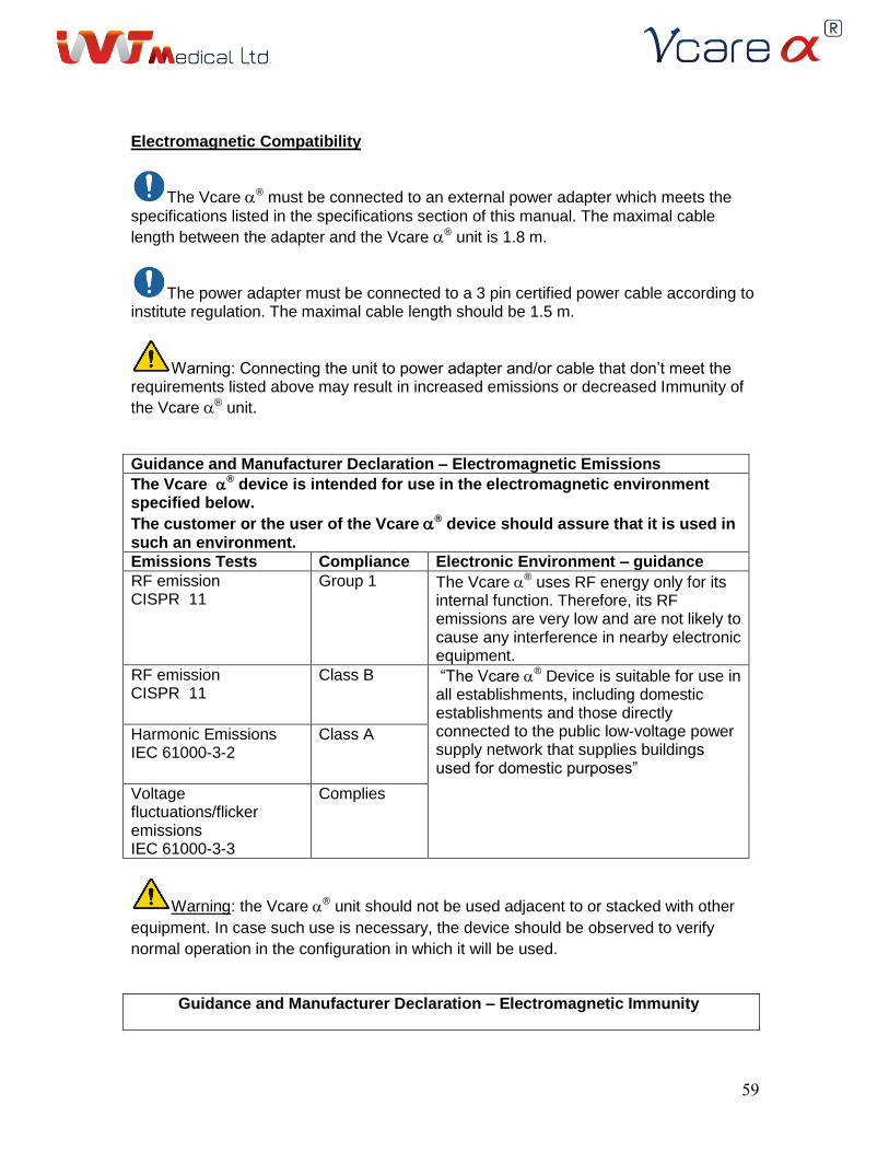
59
Electromagnetic Compatibility
The Vcare ® must be connected to an external power adapter which meets the
specifications listed in the specifications section of this manual. The maximal cable
length between the adapter and the Vcare ® unit is 1.8 m.
The power adapter must be connected to a 3 pin certified power cable according to institute regulation. The maximal cable length should be 1.5 m.
Warning: Connecting the unit to power adapter and/or cable that don’t meet the requirements listed above may result in increased emissions or decreased Immunity of
the Vcare ® unit.
Guidance and Manufacturer Declaration – Electromagnetic Emissions
The Vcare ® device is intended for use in the electromagnetic environment specified below.
The customer or the user of the Vcare ® device should assure that it is used in such an environment.
Emissions Tests Compliance Electronic Environment – guidance
RF emission CISPR 11
Group 1 The Vcare ® uses RF energy only for its internal function. Therefore, its RF emissions are very low and are not likely to cause any interference in nearby electronic equipment.
RF emission CISPR 11
Class B “The Vcare ® Device is suitable for use in all establishments, including domestic establishments and those directly connected to the public low-voltage power supply network that supplies buildings used for domestic purposes”
Harmonic Emissions IEC 61000-3-2
Class A
Voltage fluctuations/flicker emissions IEC 61000-3-3
Complies
Warning: the Vcare ® unit should not be used adjacent to or stacked with other
equipment. In case such use is necessary, the device should be observed to verify
normal operation in the configuration in which it will be used.
Guidance and Manufacturer Declaration – Electromagnetic Immunity
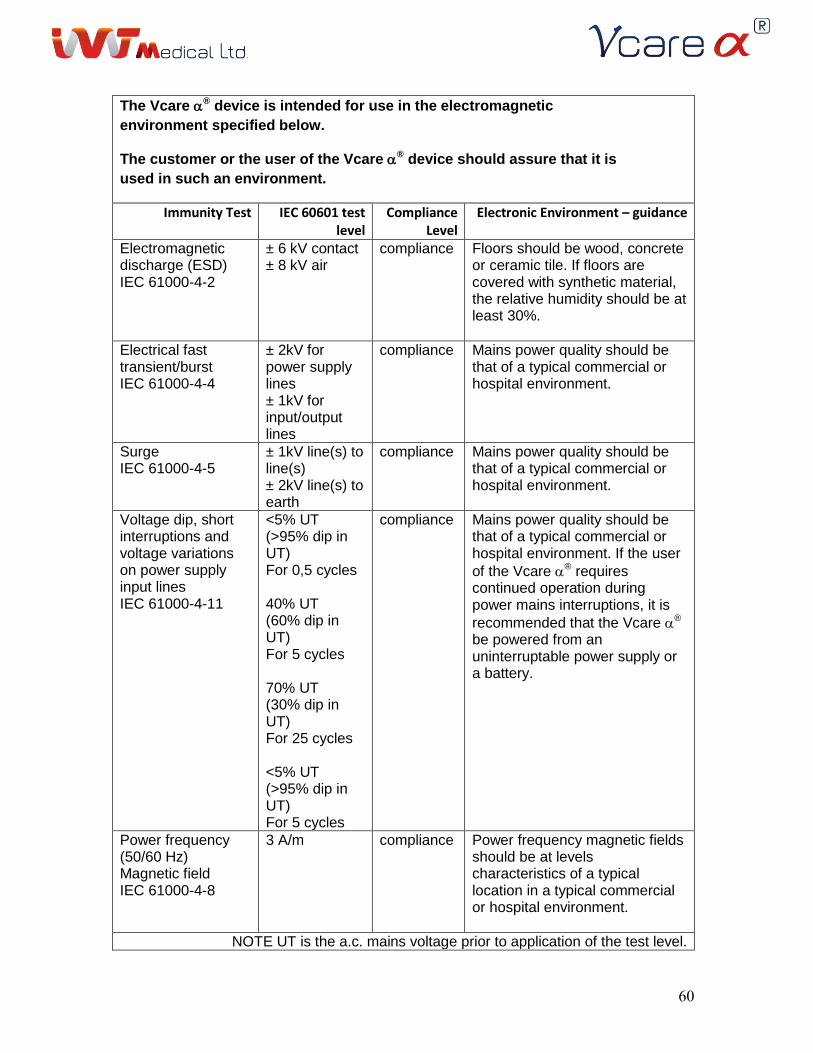
61
The Vcare ® device is intended for use in the electromagnetic
environment specified below.
The customer or the user of the Vcare ® device should assure that it is
used in such an environment.
Immunity Test IEC 60601 test level
Compliance Level
Electronic Environment – guidance
Electromagnetic discharge (ESD) IEC 61000-4-2
± 6 kV contact ± 8 kV air
compliance
Floors should be wood, concrete or ceramic tile. If floors are covered with synthetic material, the relative humidity should be at least 30%.
Electrical fast transient/burst IEC 61000-4-4
± 2kV for power supply lines ± 1kV for input/output lines
compliance Mains power quality should be that of a typical commercial or hospital environment.
Surge IEC 61000-4-5
± 1kV line(s) to line(s) ± 2kV line(s) to earth
compliance Mains power quality should be that of a typical commercial or hospital environment.
Voltage dip, short interruptions and voltage variations on power supply input lines IEC 61000-4-11
<5% UT (>95% dip in UT) For 0,5 cycles
40% UT (60% dip in UT) For 5 cycles
70% UT (30% dip in UT) For 25 cycles
<5% UT (>95% dip in UT) For 5 cycles
compliance Mains power quality should be that of a typical commercial or hospital environment. If the user
of the Vcare ® requires continued operation during power mains interruptions, it is
recommended that the Vcare ® be powered from an uninterruptable power supply or a battery.
Power frequency (50/60 Hz) Magnetic field IEC 61000-4-8
3 A/m compliance Power frequency magnetic fields should be at levels characteristics of a typical location in a typical commercial or hospital environment.
NOTE UT is the a.c. mains voltage prior to application of the test level.
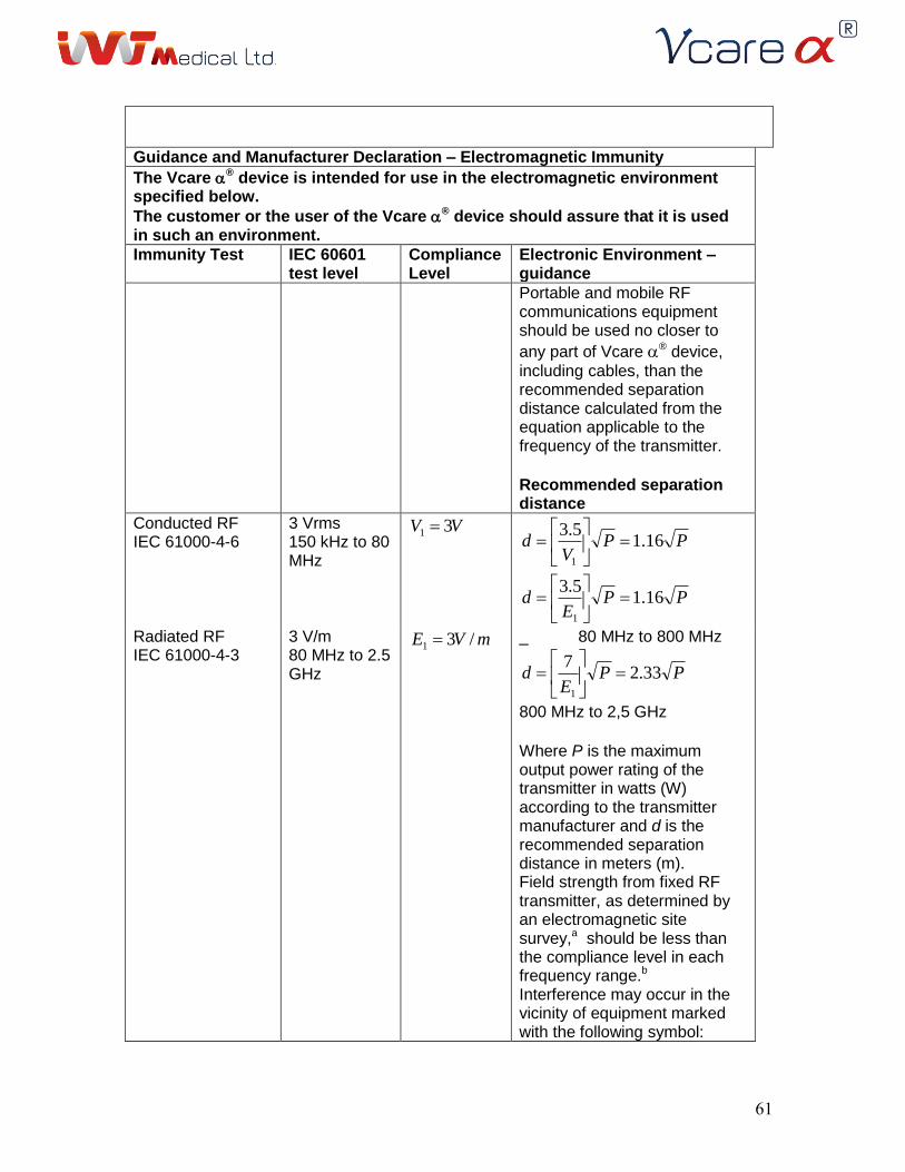
61
Guidance and Manufacturer Declaration – Electromagnetic Immunity
The Vcare ® device is intended for use in the electromagnetic environment specified below.
The customer or the user of the Vcare ® device should assure that it is used in such an environment.
Immunity Test IEC 60601 test level
Compliance Level
Electronic Environment – guidance
Portable and mobile RF communications equipment should be used no closer to
any part of Vcare ® device,
including cables, than the recommended separation distance calculated from the equation applicable to the frequency of the transmitter. Recommended separation distance
Conducted RF IEC 61000-4-6
3 Vrms 150 kHz to 80 MHz
VV 31 PP
Vd 16.1
5.3
1
PPE
d 16.15.3
1
Radiated RF IEC 61000-4-3
3 V/m 80 MHz to 2.5 GHz
mVE /31
_ 80 MHz to 800 MHz
PPE
d 33.27
1
800 MHz to 2,5 GHz Where P is the maximum output power rating of the transmitter in watts (W) according to the transmitter manufacturer and d is the recommended separation distance in meters (m). Field strength from fixed RF transmitter, as determined by an electromagnetic site survey,a should be less than the compliance level in each frequency range.b
Interference may occur in the vicinity of equipment marked with the following symbol:
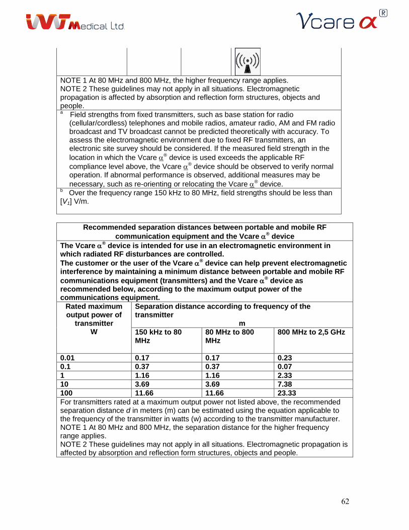
62
NOTE 1 At 80 MHz and 800 MHz, the higher frequency range applies. NOTE 2 These guidelines may not apply in all situations. Electromagnetic propagation is affected by absorption and reflection form structures, objects and people. a Field strengths from fixed transmitters, such as base station for radio
(cellular/cordless) telephones and mobile radios, amateur radio, AM and FM radio broadcast and TV broadcast cannot be predicted theoretically with accuracy. To assess the electromagnetic environment due to fixed RF transmitters, an electronic site survey should be considered. If the measured field strength in the
location in which the Vcare ® device is used exceeds the applicable RF
compliance level above, the Vcare ® device should be observed to verify normal operation. If abnormal performance is observed, additional measures may be
necessary, such as re-orienting or relocating the Vcare ® device. b Over the frequency range 150 kHz to 80 MHz, field strengths should be less than [V1] V/m.
Recommended separation distances between portable and mobile RF
communication equipment and the Vcare ® device
The Vcare ® device is intended for use in an electromagnetic environment in which radiated RF disturbances are controlled.
The customer or the user of the Vcare ® device can help prevent electromagnetic interference by maintaining a minimum distance between portable and mobile RF
communications equipment (transmitters) and the Vcare ® device as recommended below, according to the maximum output power of the communications equipment.
Rated maximum output power of
transmitter W
Separation distance according to frequency of the transmitter
m
150 kHz to 80 MHz
80 MHz to 800 MHz
800 MHz to 2,5 GHz
0.01 0.17 0.17 0.23
0.1 0.37 0.37 0.07
1 1.16 1.16 2.33
10 3.69 3.69 7.38
100 11.66 11.66 23.33
For transmitters rated at a maximum output power not listed above, the recommended separation distance d in meters (m) can be estimated using the equation applicable to the frequency of the transmitter in watts (w) according to the transmitter manufacturer. NOTE 1 At 80 MHz and 800 MHz, the separation distance for the higher frequency range applies. NOTE 2 These guidelines may not apply in all situations. Electromagnetic propagation is affected by absorption and reflection form structures, objects and people.
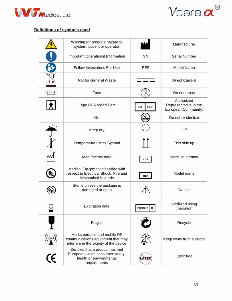
63
Definitions of symbols used
Warning for possible hazard to system, patient or operator
Manufacturer
Important Operational Information SN Serial Number
Follow Instructions For Use REF Model Name
Not for General Waste
Direct Current
Fuse
Do not reuse
Type BF Applied Part
Authorized Representative in the European Community.
On
Do not re-sterilize
Keep dry
Off
Temperature Limits Symbol
This side up
Manufactory date
Batch lot number
Medical Equipment classified with respect to Electrical Shock, Fire and
Mechanical Hazards
Model name
Sterile unless the package is damaged or open
Caution
Expiration date
Sterilized using irradiation
Fragile
Recycle
Marks portable and mobile RF communications equipment that may interfere in the vicinity of the device
Keep away from sunlight
Certifies that a product has met European Union consumer safety,
health or environmental requirements
Latex free
64
Biohazard
IVT Medical Ltd. 16 Hatidhar St. Ra’anana 43665 Israel Phone: +972-9-7463737 Fax: +972-9-7604506
Obelis s.a Bd. Général Wahis 53 1030 Brussels, BELGIUM Tel: +(32) 2. 732.59.54 Fax: +(32) 2.732.60.03 E‐Mail : [email protected]
July 2014 Rev. 0.3-F SW Ver. 0.2