Embed Size (px)
Citation preview
www.gys.fr
USER MANUAL V1
TABLE OF CONTENTS
1 - PRESENTATION, SAFETY RECOMMENDATIONS AND GENERAL PRECAUTIONS ................................... 2
2 - DESCRIPTION .............................................................................................................................. 3
- Front panel ........................................................................................................................................ 3
- Rear panel ......................................................................................................................................... 3
- Clamps .............................................................................................................................................. 3
3 - INSTALLATION ............................................................................................................................. 4
4 –EQUIPMENT OPERATION ............................................................................................................... 5
- Key definition ..................................................................................................................................... 5
- Use of the C clamp ............................................................................................................................. 6-7
- Use of the X clamp ............................................................................................................................ 8-9
- Use of the single sided gun ................................................................................................................. 10
- Error management ............................................................................................................................. 11
- Welding spots counter ........................................................................................................................ 12
- Recording features (identification mode – user’s parameters) ............................................................... 13-14
- SD memory card ................................................................................................................................ 15
- GYSPOT software on PC ..................................................................................................................... 15-16
5 - PRECAUTIONS AND SERVICING ..................................................................................................... 17
- Relacement of caps/electrodes ............................................................................................................ 17
- Cleaning or replacement of welding tools ............................................................................................. 17
- purge of th epneumatic filter ............................................................................................................... 17
- maintenance of the generator ............................................................................................................. 17
- Replacement and adjustment of X arms............................................................................................... 18
- Replacement and adjustment of C arms .............................................................................................. 19
6 – ASSEMBLY INSTRUCTIONS ........................................................................................................... 20-21
7 – TECHNICAL CHARACTERISTICS ..................................................................................................... 22
8 - ANOMALIES / CAUSES / REMEDIES ................................................................................................ 23
9 - ICONS ......................................................................................................................................... 24
10 – DECLARATION OF CONFORMITY ................................................................................................. 24
11 – WARRANTY ................................................................................................................................ 25
12 – CIRCUIT DIAGRAM ..................................................................................................................... 26-27
73502 18/01/2019_V4
Autres langues disponibles sur la carte SD. Other languages available on the SD card. Weitere auf SD-Karte verfügbare Sprachen.
2
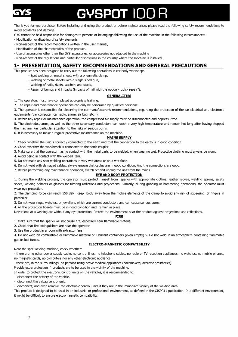
Thank you for yourpurchase! Before installing and using the product or before maintenance, please read the following safety recommendations to
avoid accidents and damage.
GYS cannot be held responsible for damages to persons or belongings following the use of the machine in the following circumstances:
- Modification or disabling of safety elements,
- Non-respect of the recommendations written in the user manual,
- Modification of the characteristics of the product,
- Use of accessories other than the GYS accessories, or accessories not adapted to the machine
- Non-respect of the regulations and particular dispositions in the country where the machine is installed.
1- PRESENTATION, SAFETY RECOMMENDATIONS AND GENERAL PRECAUTIONS This product has been designed to carry out the following operations in car body workshops:
- Spot welding on metal sheets with a pneumatic clamp,
- Welding of metal sheets with a single sided gun,
- Welding of nails, rivets, washers and studs,
- Repair of bumps and impacts (impacts of hail with the option « quick repair”).
GENERALITIES
1. The operators must have completed appropriate training.
2. The repair and maintenance operations can only be performed by qualified personnel.
3. The operator is responsible for observing the car manufacturer’s recommendations, regarding the protection of the car electrical and electronic
equipments (car computer, car radio, alarm, air bag, etc…).
4. Before any repair or maintenance operation, the compressed air supply must be disconnected and depressurized.
5. The electrodes, arms, as well as the other secondary conductors can reach a very high temperature and remain hot long after having stopped
the machine. Pay particular attention to the risks of serious burns.
6. It is necessary to make a regular preventive maintenance on the machine.
MAINS SUPPLY
1. Check whether the unit is correctly connected to the earth and that the connection to the earth is in good condition.
2. Check whether the workbench is connected to the earth coupler.
3. Make sure that the operator has no contact with the metal parts to be welded, when wearing wet. Protective clothing must always be worn.
4. Avoid being in contact with the welded item.
5. Do not make any spot welding operations in very wet areas or on a wet floor.
6. Do not weld with damaged cables, always ensure that cables are in good condition. And the connections are good.
7. Before performing any maintenance operation, switch off and unplug the unit from the mains.
EYE AND BODY PROTECTION
1. During the welding process, the operator must protect himself from sparks with appropriate clothes: leather gloves, welding aprons, safety
shoes, welding helmets or glasses for filtering radiations and projections. Similarly, during grinding or hammering operations, the operator must
wear eye protection.
2. The clamping force can reach 550 daN. Keep body away from the mobile elements of the clamp to avoid any risk of squeezing, of fingers in
particular.
3. Do not wear rings, watches, or jewellery, which are current conductors and can cause serious burns.
4. All the protection boards must be in good condition and remain in place.
Never look at a welding arc without any eye protection. Protect the environment near the product against projections and reflections.
FIRE
1. Make sure that the sparks will not cause fire, especially near flammable material.
2. Check that fire extinguishers are near the operator.
3. Use the product in a room with extractor fans
4. Do not weld on combustible or flammable material or lubricant containers (even empty) 5. Do not weld in an atmosphere containing flammable
gas or fuel fumes.
ELECTRO-MAGNETIC COMPATIBILITY
Near the spot-welding machine, check whether:
- there are no other power supply cable, no control lines, no telephone cables, no radio or TV reception appliances, no watches, no mobile phones,
no magnetic cards, no computers nor any other electronic appliance.
- there are, in the surroundings, no persons using active medical appliances (pacemakers, acoustic prosthetics).
Provide extra protection if products are to be used in the vicinity of the machine.
In order to protect the electronic control units on the vehicles, it is recommended to:
- disconnect the battery of the vehicle.
- disconnect the airbag control unit.
- disconnect, and even remove, the electronic control units if they are in the immediate vicinity of the welding area.
This product is designed to be used in an industrial or professional environment, as defined in the CISPR11 publication. In a different environment,
it might be difficult to ensure electromagnetic compatibility.
3
CE MARKING
GYS testifies that this product has been designed and manufactured in conformity with the following European
standards:
- Low Voltage Directive 2006/95/EC in application of the norm EN 62135-1
- Electromagnetic Compatibility Directive EMC 2004/108/EC in application of the norm EN 62135-2
- Machines directive 2006/95/EC in application of the norm EN 60204-1
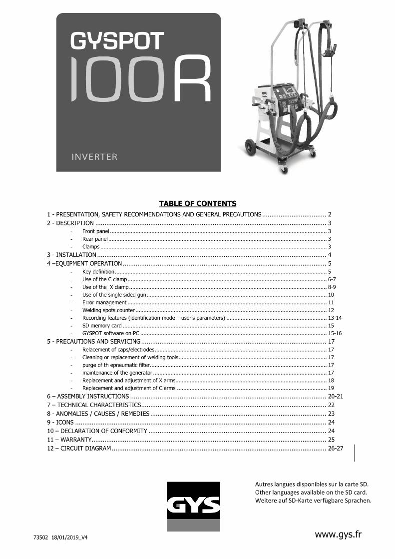
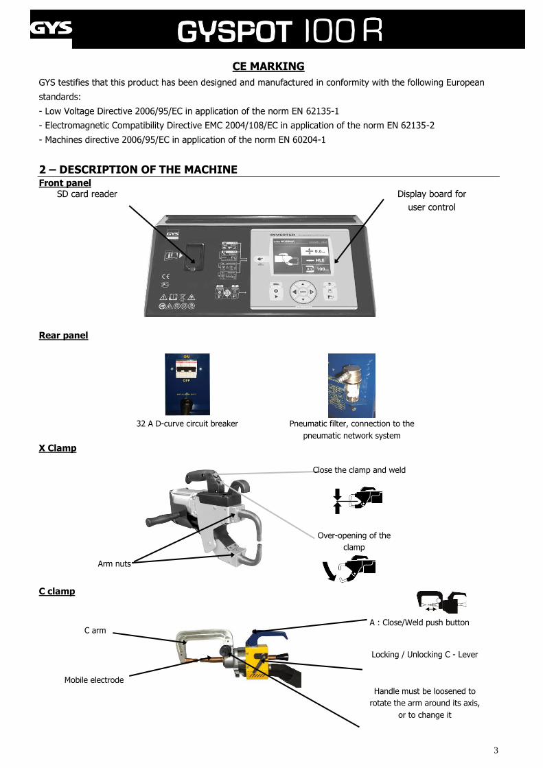
2 – DESCRIPTION OF THE MACHINE Front panel
SD card reader
Display board for
user control
Rear panel
32 A D-curve circuit breaker Pneumatic filter, connection to the
pneumatic network system
X Clamp
C clamp
C arm
Mobile electrode
A : Close/Weld push button
Locking / Unlocking C - Lever
Handle must be loosened to
rotate the arm around its axis,
or to change it
Over-opening of the
clamp
Close the clamp and weld
Arm nuts
4
3- INSTALLATION
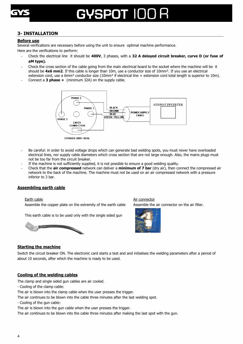
Before use Several verifications are necessary before using the unit to ensure optimal machine performance.
Here are the verifications to perform:
- Check the electrical line it should be 400V, 3 phases, with a 32 A delayed circuit breaker, curve D (or fuse of
aM type).
- Check the cross section of the cable going from the main electrical board to the socket where the machine will be it should be 4x6 mm2. If this cable is longer than 10m, use a conductor size of 10mm². If you use an electrical extension cord, use a 6mm² conductor size (10mm² if electrical line + extension cord total length is superior to 10m).
- Connect a 3 phase + (minimum 32A) on the supply cable.
- Be careful: in order to avoid voltage drops which can generate bad welding spots, you must never have overloaded electrical lines, nor supply cable diameters which cross section that are not large enough. Also, the mains plugs must not be too far from the circuit breaker.
- If the machine is not sufficiently supplied, it is not possible to ensure a good welding quality. - Check that the air compressed network can deliver a minimum of 7 bar (dry air), then connect the compressed air
network to the back of the machine. The machine must not be used on an air compressed network with a pressure inferior to 3 bar.
Assembling earth cable
Earth cable Air connector
Assemble the copper plate on the extremity of the earth cable Assemble the air connector on the air filter.
This earth cable is to be used only with the single sided gun
Starting the machine
Switch the circuit breaker ON. The electronic card starts a test and and initialises the welding parameters after a period of
about 10 seconds, after which the machine is ready to be used.
Cooling of the welding cables
The clamp and single sided gun cables are air cooled.
- Cooling of the clamp cable:
The air is blown into the clamp cable when the user presses the trigger.
The air continues to be blown into the cable three minutes after the last welding spot.
- Cooling of the gun cable:
The air is blown into the gun cable when the user presses the trigger.
The air continues to be blown into the cable three minutes after making the last spot with the gun.
5
4- EQUIPMENT OPERATION
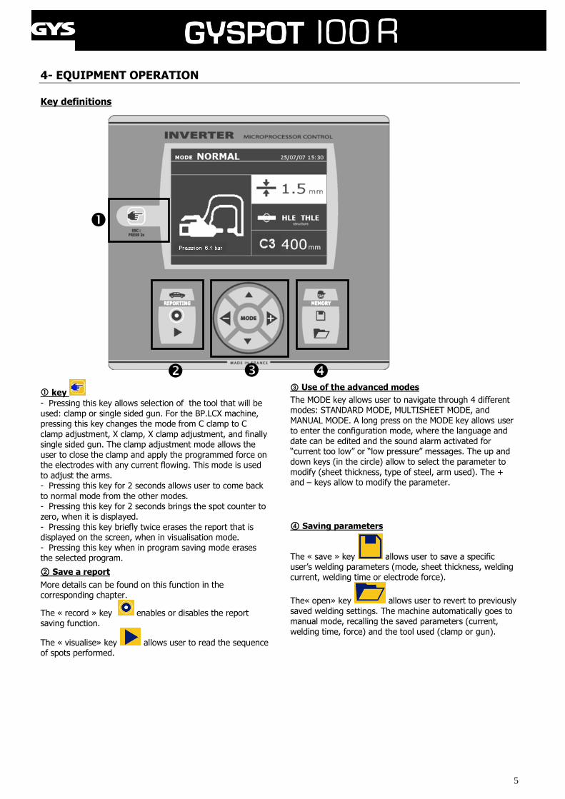
Key definitions
key
- Pressing this key allows selection of the tool that will be used: clamp or single sided gun. For the BP.LCX machine, pressing this key changes the mode from C clamp to C clamp adjustment, X clamp, X clamp adjustment, and finally single sided gun. The clamp adjustment mode allows the user to close the clamp and apply the programmed force on the electrodes with any current flowing. This mode is used to adjust the arms. - Pressing this key for 2 seconds allows user to come back to normal mode from the other modes. - Pressing this key for 2 seconds brings the spot counter to zero, when it is displayed. - Pressing this key briefly twice erases the report that is displayed on the screen, when in visualisation mode. - Pressing this key when in program saving mode erases the selected program.
② Save a report
More details can be found on this function in the corresponding chapter.
The « record » key enables or disables the report saving function.
The « visualise» key allows user to read the sequence of spots performed.
③ Use of the advanced modes
The MODE key allows user to navigate through 4 different modes: STANDARD MODE, MULTISHEET MODE, and MANUAL MODE. A long press on the MODE key allows user to enter the configuration mode, where the language and date can be edited and the sound alarm activated for “current too low” or “low pressure” messages. The up and down keys (in the circle) allow to select the parameter to modify (sheet thickness, type of steel, arm used). The + and – keys allow to modify the parameter.
④ Saving parameters
The « save » key allows user to save a specific user’s welding parameters (mode, sheet thickness, welding current, welding time or electrode force).
The« open» key allows user to revert to previously saved welding settings. The machine automatically goes to manual mode, recalling the saved parameters (current,
welding time, force) and the tool used (clamp or gun).
6
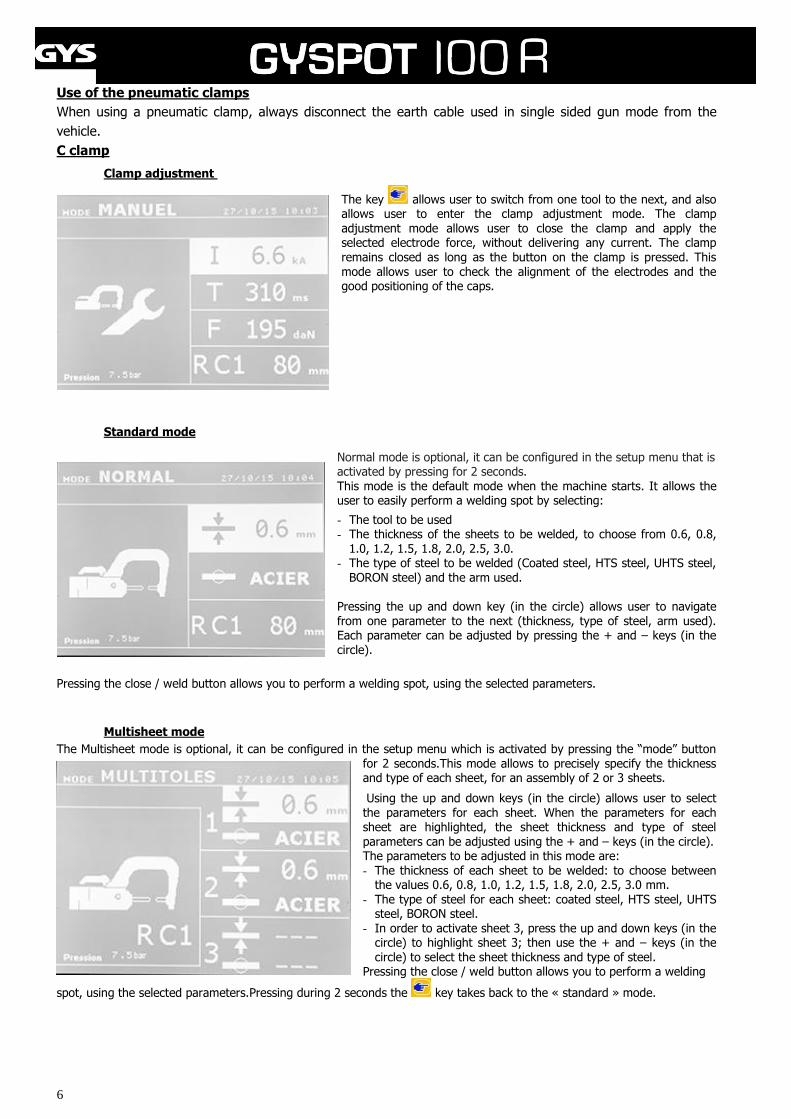
Use of the pneumatic clamps
When using a pneumatic clamp, always disconnect the earth cable used in single sided gun mode from the
vehicle.
C clamp
Clamp adjustment
The key allows user to switch from one tool to the next, and also allows user to enter the clamp adjustment mode. The clamp adjustment mode allows user to close the clamp and apply the selected electrode force, without delivering any current. The clamp remains closed as long as the button on the clamp is pressed. This mode allows user to check the alignment of the electrodes and the good positioning of the caps.
Standard mode
Normal mode is optional, it can be configured in the setup menu that is activated by pressing for 2 seconds. This mode is the default mode when the machine starts. It allows the user to easily perform a welding spot by selecting:
- The tool to be used - The thickness of the sheets to be welded, to choose from 0.6, 0.8,
1.0, 1.2, 1.5, 1.8, 2.0, 2.5, 3.0. - The type of steel to be welded (Coated steel, HTS steel, UHTS steel,
BORON steel) and the arm used.
Pressing the up and down key (in the circle) allows user to navigate from one parameter to the next (thickness, type of steel, arm used). Each parameter can be adjusted by pressing the + and – keys (in the circle).
Pressing the close / weld button allows you to perform a welding spot, using the selected parameters.
Multisheet mode
The Multisheet mode is optional, it can be configured in the setup menu which is activated by pressing the “mode” button for 2 seconds.This mode allows to precisely specify the thickness and type of each sheet, for an assembly of 2 or 3 sheets.
Using the up and down keys (in the circle) allows user to select the parameters for each sheet. When the parameters for each sheet are highlighted, the sheet thickness and type of steel parameters can be adjusted using the + and – keys (in the circle). The parameters to be adjusted in this mode are: - The thickness of each sheet to be welded: to choose between
the values 0.6, 0.8, 1.0, 1.2, 1.5, 1.8, 2.0, 2.5, 3.0 mm. - The type of steel for each sheet: coated steel, HTS steel, UHTS
steel, BORON steel. - In order to activate sheet 3, press the up and down keys (in the
circle) to highlight sheet 3; then use the + and – keys (in the circle) to select the sheet thickness and type of steel.
Pressing the close / weld button allows you to perform a welding
spot, using the selected parameters.Pressing during 2 seconds the key takes back to the « standard » mode.
7
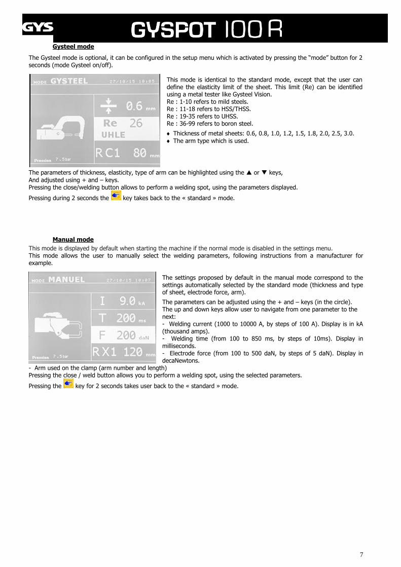
Gysteel mode
The Gysteel mode is optional, it can be configured in the setup menu which is activated by pressing the “mode” button for 2 seconds (mode Gysteel on/off).
This mode is identical to the standard mode, except that the user can define the elasticity limit of the sheet. This limit (Re) can be identified using a metal tester like Gysteel Vision. Re : 1-10 refers to mild steels. Re : 11-18 refers to HSS/THSS. Re : 19-35 refers to UHSS. Re : 36-99 refers to boron steel.
Thickness of metal sheets: 0.6, 0.8, 1.0, 1.2, 1.5, 1.8, 2.0, 2.5, 3.0.
The arm type which is used.
The parameters of thickness, elasticity, type of arm can be highlighted using the or keys,
And adjusted using + and – keys. Pressing the close/welding button allows to perform a welding spot, using the parameters displayed.
Pressing during 2 seconds the key takes back to the « standard » mode.
Manual mode
This mode is displayed by default when starting the machine if the normal mode is disabled in the settings menu. This mode allows the user to manually select the welding parameters, following instructions from a manufacturer for example.
The settings proposed by default in the manual mode correspond to the settings automatically selected by the standard mode (thickness and type of sheet, electrode force, arm).
The parameters can be adjusted using the + and – keys (in the circle). The up and down keys allow user to navigate from one parameter to the next: - Welding current (1000 to 10000 A, by steps of 100 A). Display is in kA (thousand amps). - Welding time (from 100 to 850 ms, by steps of 10ms). Display in milliseconds. - Electrode force (from 100 to 500 daN, by steps of 5 daN). Display in decaNewtons.
- Arm used on the clamp (arm number and length) Pressing the close / weld button allows you to perform a welding spot, using the selected parameters.
Pressing the key for 2 seconds takes user back to the « standard » mode.
8
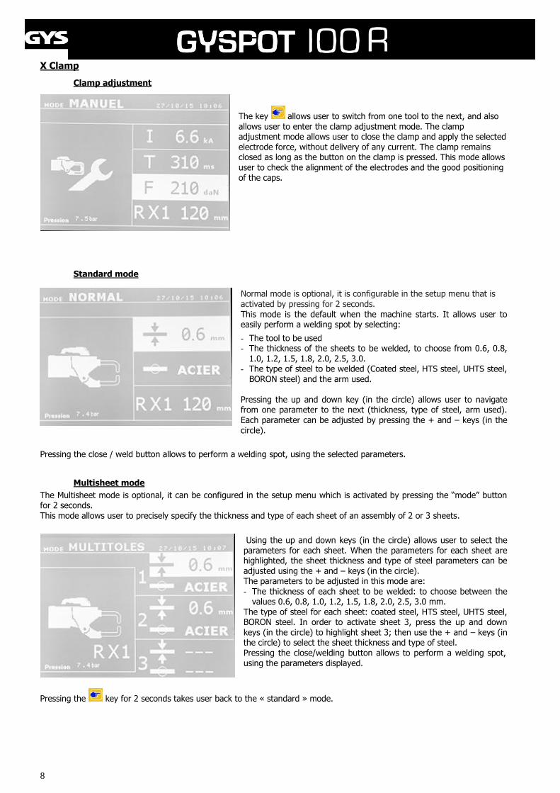
X Clamp
Clamp adjustment
The key allows user to switch from one tool to the next, and also allows user to enter the clamp adjustment mode. The clamp adjustment mode allows user to close the clamp and apply the selected electrode force, without delivery of any current. The clamp remains closed as long as the button on the clamp is pressed. This mode allows user to check the alignment of the electrodes and the good positioning of the caps.
Standard mode
Normal mode is optional, it is configurable in the setup menu that is activated by pressing for 2 seconds. This mode is the default when the machine starts. It allows user to easily perform a welding spot by selecting:
- The tool to be used - The thickness of the sheets to be welded, to choose from 0.6, 0.8,
1.0, 1.2, 1.5, 1.8, 2.0, 2.5, 3.0. - The type of steel to be welded (Coated steel, HTS steel, UHTS steel,
BORON steel) and the arm used. Pressing the up and down key (in the circle) allows user to navigate from one parameter to the next (thickness, type of steel, arm used).
Each parameter can be adjusted by pressing the + and – keys (in the circle).
Pressing the close / weld button allows to perform a welding spot, using the selected parameters.
Multisheet mode
The Multisheet mode is optional, it can be configured in the setup menu which is activated by pressing the “mode” button for 2 seconds. This mode allows user to precisely specify the thickness and type of each sheet of an assembly of 2 or 3 sheets.
Using the up and down keys (in the circle) allows user to select the parameters for each sheet. When the parameters for each sheet are highlighted, the sheet thickness and type of steel parameters can be adjusted using the + and – keys (in the circle). The parameters to be adjusted in this mode are:
- The thickness of each sheet to be welded: to choose between the values 0.6, 0.8, 1.0, 1.2, 1.5, 1.8, 2.0, 2.5, 3.0 mm.
The type of steel for each sheet: coated steel, HTS steel, UHTS steel, BORON steel. In order to activate sheet 3, press the up and down keys (in the circle) to highlight sheet 3; then use the + and – keys (in the circle) to select the sheet thickness and type of steel. Pressing the close/welding button allows to perform a welding spot, using the parameters displayed.
Pressing the key for 2 seconds takes user back to the « standard » mode.
9
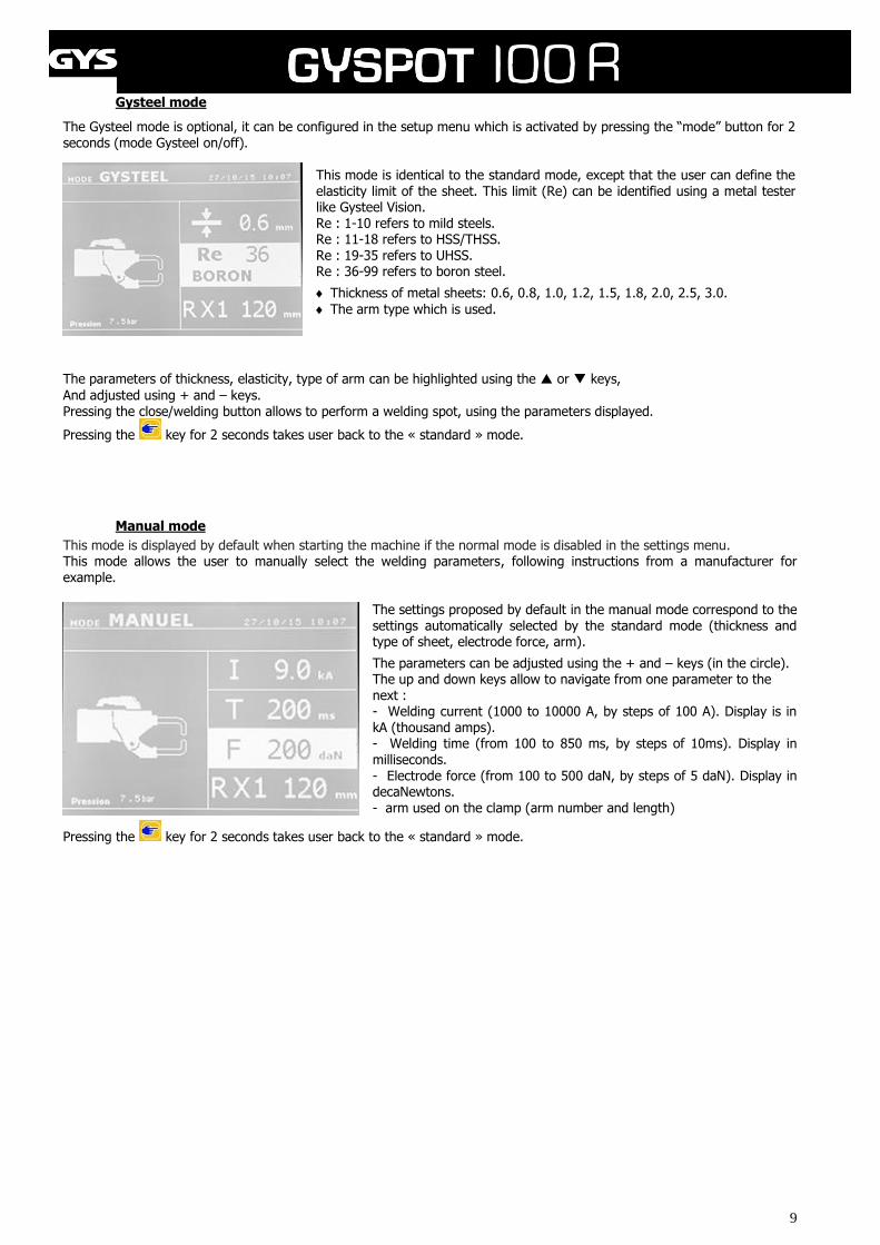
Gysteel mode
The Gysteel mode is optional, it can be configured in the setup menu which is activated by pressing the “mode” button for 2 seconds (mode Gysteel on/off).
This mode is identical to the standard mode, except that the user can define the elasticity limit of the sheet. This limit (Re) can be identified using a metal tester like Gysteel Vision. Re : 1-10 refers to mild steels. Re : 11-18 refers to HSS/THSS. Re : 19-35 refers to UHSS. Re : 36-99 refers to boron steel.
Thickness of metal sheets: 0.6, 0.8, 1.0, 1.2, 1.5, 1.8, 2.0, 2.5, 3.0.
The arm type which is used.
The parameters of thickness, elasticity, type of arm can be highlighted using the or keys,
And adjusted using + and – keys. Pressing the close/welding button allows to perform a welding spot, using the parameters displayed.
Pressing the key for 2 seconds takes user back to the « standard » mode.
Manual mode
This mode is displayed by default when starting the machine if the normal mode is disabled in the settings menu. This mode allows the user to manually select the welding parameters, following instructions from a manufacturer for example.
The settings proposed by default in the manual mode correspond to the settings automatically selected by the standard mode (thickness and type of sheet, electrode force, arm).
The parameters can be adjusted using the + and – keys (in the circle). The up and down keys allow to navigate from one parameter to the next : - Welding current (1000 to 10000 A, by steps of 100 A). Display is in kA (thousand amps). - Welding time (from 100 to 850 ms, by steps of 10ms). Display in milliseconds. - Electrode force (from 100 to 500 daN, by steps of 5 daN). Display in decaNewtons. - arm used on the clamp (arm number and length)
Pressing the key for 2 seconds takes user back to the « standard » mode.
10
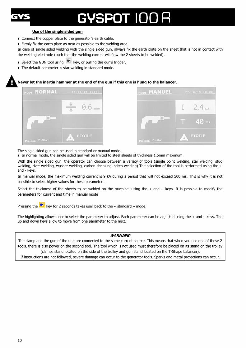
Use of the single sided gun
Connect the copper plate to the generator’s earth cable.
Firmly fix the earth plate as near as possible to the welding area.
In case of single sided welding with the single sided gun, always fix the earth plate on the sheet that is not in contact with
the welding electrode (such that the welding current will flow the 2 sheets to be welded).
Select the GUN tool using key, or pulling the gun’s trigger.
The default parameter is star welding in standard mode.
-
Never let the inertia hammer at the end of the gun if this one is hung to the balancer.
The single sided gun can be used in standard or manual mode. In normal mode, the single sided gun will be limited to steel sheets of thickness 1.5mm maximum.
With the single sided gun, the operator can choose between a variety of tools (single point welding, star welding, stud welding, rivet welding, washer welding, carbon shrinking, stitch welding) The selection of the tool is performed using the + and - keys.
In manual mode, the maximum welding current is 9 kA during a period that will not exceed 500 ms. This is why it is not
possible to select higher values for these parameters.
Select the thickness of the sheets to be welded on the machine, using the + and – keys. It is possible to modify the
parameters for current and time in manual mode
Pressing the key for 2 seconds takes user back to the « standard » mode.
The highlighting allows user to select the parameter to adjust. Each parameter can be adjusted using the + and – keys. The up and down keys allow to move from one parameter to the next.
WARNING:
The clamp and the gun of the unit are connected to the same current source. This means that when you use one of these 2
tools, there is also power on the second tool. The tool which is not used must therefore be placed on its stand on the trolley
(clamps stand located on the side of the trolley and gun stand located on the T-Shape balancer).
If instructions are not followed, severe damage can occur to the generator tools. Sparks and metal projections can occur.
!
11
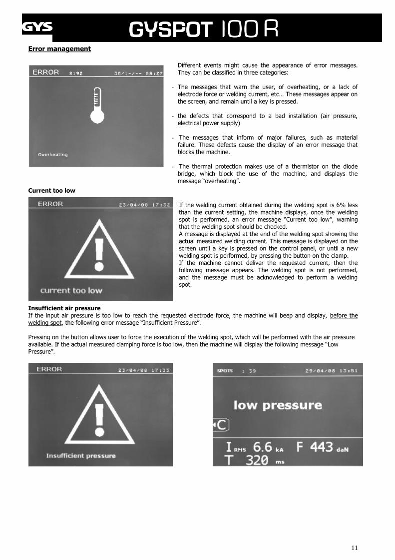
Error management
Different events might cause the appearance of error messages. They can be classified in three categories:
- The messages that warn the user, of overheating, or a lack of electrode force or welding current, etc… These messages appear on the screen, and remain until a key is pressed.
- the defects that correspond to a bad installation (air pressure, electrical power supply)
- The messages that inform of major failures, such as material failure. These defects cause the display of an error message that blocks the machine.
- The thermal protection makes use of a thermistor on the diode bridge, which block the use of the machine, and displays the
message “overheating”.
Current too low If the welding current obtained during the welding spot is 6% less than the current setting, the machine displays, once the welding spot is performed, an error message “Current too low”, warning that the welding spot should be checked. A message is displayed at the end of the welding spot showing the actual measured welding current. This message is displayed on the screen until a key is pressed on the control panel, or until a new welding spot is performed, by pressing the button on the clamp. If the machine cannot deliver the requested current, then the following message appears. The welding spot is not performed, and the message must be acknowledged to perform a welding spot.
Insufficient air pressure If the input air pressure is too low to reach the requested electrode force, the machine will beep and display, before the welding spot, the following error message “Insufficient Pressure”. Pressing on the button allows user to force the execution of the welding spot, which will be performed with the air pressure available. If the actual measured clamping force is too low, then the machine will display the following message “Low Pressure”.
12
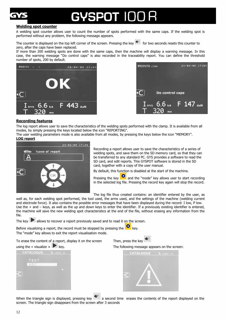
Welding spot counter
A welding spot counter allows user to count the number of spots performed with the same caps. If the welding spot is
performed without any problem, the following message appears.
The counter is displayed on the top left corner of the screen. Pressing the key for two seconds resets this counter to zero, after the caps have been replaced. If more than 200 welding spots are done with the same caps, then the machine will display a warning message. In this case, the warning message “Do control caps” is also recorded in the traceability report. You can define the threshold number of spots, 200 by default.
Recording features
The log report allows user to save the characteristics of the welding spots performed with the clamp. It is available from all modes, by simply pressing the keys located below the icon “REPORTING”. The user welding parameters mode is also available from all modes, by pressing the keys below the icon “MEMORY”. LOG report
Recording a report allows user to save the characteristics of a series of welding spots, and save them on the SD memory card, so that they can be transferred to any standard PC. GYS provides a software to read the SD card, and edit reports. This GYSPOT software is stored in the SD card, together with a copy of the user manual.
By default, this function is disabled at the start of the machine.
Pressing the key and the “mode” key allows user to start recording in the selected log file. Pressing the record key again will stop the record. The log file thus created contains: an identifier entered by the user, as
well as, for each welding spot performed, the tool used, the arms used, and the settings of the machine (welding current and electrode force). It also contains the possible error messages that have been displayed during the record: I low, P low. Use the + and – keys, as well as the up and down keys to enter the identifier. If a previously existing identifier is entered, the machine will save the new welding spot characteristics at the end of the file, without erasing any information from the file.
The key allows to recover a report previously saved and to read it on the screen.
Before visualizing a report, the record must be stopped by pressing the key.
The “mode” key allows to exit the report visualisation mode.
To erase the content of a report, display it on the screen Then, press the key
using the « visualize » key. The following message appears on the screen:
When the triangle sign is displayed, pressing key a second time erases the contents of the report displayed on the
screen. The triangle sign disappears from the screen after 3 seconds
13
Identification mode :
If the identification mode is set to "ON", then you should enter the data for all required fields otherwise the machine will show the "defect identification” error message. To enable and disable the identification mode, insert an identification SD card instead of the SD card that contains the programmes. The screen below setup is activated by pressing on the mode button for 2 seconds.
When the SD card "identification" is inserted and you select
"identify ON" THEN the following SUPERVISION screen
appears.
This screen allows you to enter data in the fields
“Registration, vehicle make, vehicle model, vehicle
identification number" which are required when entering the
repair order.
To exit the screen, you must press the mode key for 2
seconds. Then you must put the SD card that contains the
program into your BP card reader.
List of screens that allow you to enter a repair order:
When a job number has already been created, it can not be changed or deleted on the BP. To remove it you must use the software GYSPOT PC. You can create up to 100 job numbers.
Display: ‘Job number‘ Display: ‘User ID‘
'left' and 'right' keys moves the cursor in the field. The up and down buttons allow you to change the letters or numbers The Esc key clears the field. The mode button allows scrolling between various fields for modification or checking.
Display: ‘Registration’ (optional) Display: ‘Vehicle make’ (optional)
14
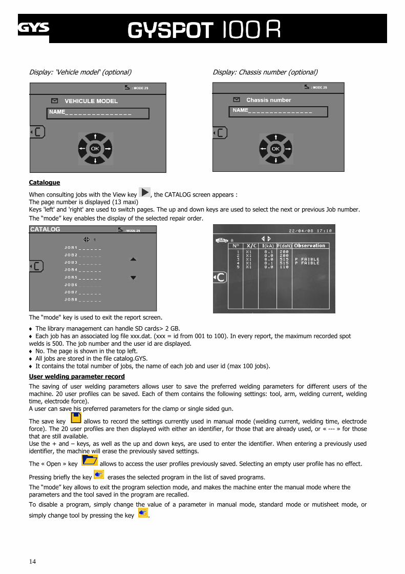
Display: ‘Vehicle model‘ (optional) Display: Chassis number (optional)
Catalogue
When consulting jobs with the View key , the CATALOG screen appears : The page number is displayed (13 maxi) Keys 'left' and 'right' are used to switch pages. The up and down keys are used to select the next or previous Job number.
The “mode” key enables the display of the selected repair order.
The “mode" key is used to exit the report screen.
The library management can handle SD cards> 2 GB.
Each job has an associated log file xxx.dat. (xxx = id from 001 to 100). In every report, the maximum recorded spot
welds is 500. The job number and the user id are displayed. No. The page is shown in the top left. All jobs are stored in the file catalog.GYS.
It contains the total number of jobs, the name of each job and user id (max 100 jobs).
User welding parameter record
The saving of user welding parameters allows user to save the preferred welding parameters for different users of the machine. 20 user profiles can be saved. Each of them contains the following settings: tool, arm, welding current, welding time, electrode force). A user can save his preferred parameters for the clamp or single sided gun.
The save key allows to record the settings currently used in manual mode (welding current, welding time, electrode
force). The 20 user profiles are then displayed with either an identifier, for those that are already used, or « --- » for those that are still available. Use the + and – keys, as well as the up and down keys, are used to enter the identifier. When entering a previously used identifier, the machine will erase the previously saved settings.
The « Open » key allows to access the user profiles previously saved. Selecting an empty user profile has no effect.
Pressing briefly the key erases the selected program in the list of saved programs.
The “mode” key allows to exit the program selection mode, and makes the machine enter the manual mode where the parameters and the tool saved in the program are recalled.
To disable a program, simply change the value of a parameter in manual mode, standard mode or mutisheet mode, or
simply change tool by pressing the key .
15
SD memory card
SD card reference: 050914
This card allows the user to transfer files from the machine to a PC to: - Collect log reports in order to keep a work trace, and possibly show it to an insurance company. - Update welding parameters, add new menu languages. - A copy of the GYSPOT software to collect and edit the traceability reports is stored on the SD card. - A copy of the user manual is also stored on the SD card.
The memory space will save the characteristics of more than a 1 000 welding spots. The machine can operate without any SD card only in manual mode.
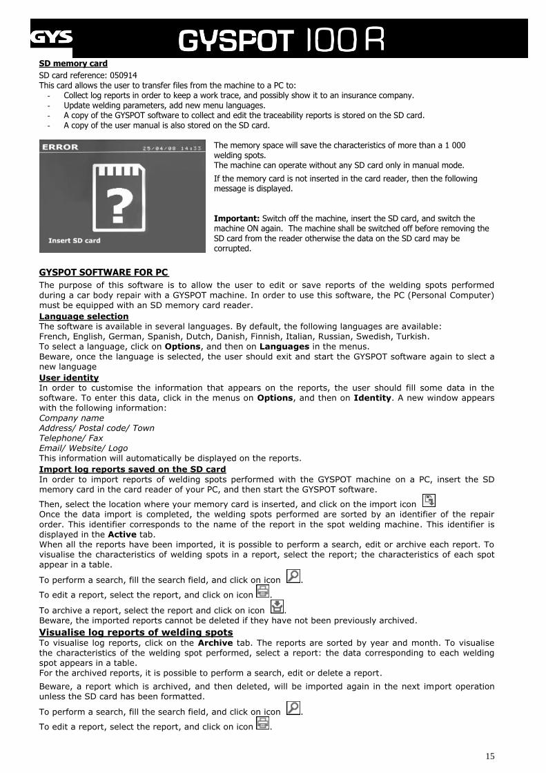
If the memory card is not inserted in the card reader, then the following message is displayed. Important: Switch off the machine, insert the SD card, and switch the machine ON again. The machine shall be switched off before removing the SD card from the reader otherwise the data on the SD card may be corrupted.
GYSPOT SOFTWARE FOR PC
The purpose of this software is to allow the user to edit or save reports of the welding spots performed
during a car body repair with a GYSPOT machine. In order to use this software, the PC (Personal Computer) must be equipped with an SD memory card reader.
Language selection The software is available in several languages. By default, the following languages are available: French, English, German, Spanish, Dutch, Danish, Finnish, Italian, Russian, Swedish, Turkish. To select a language, click on Options, and then on Languages in the menus.
Beware, once the language is selected, the user should exit and start the GYSPOT software again to slect a new language
User identity In order to customise the information that appears on the reports, the user should fill some data in the software. To enter this data, click in the menus on Options, and then on Identity. A new window appears
with the following information:
Company name Address/ Postal code/ Town Telephone/ Fax Email/ Website/ Logo This information will automatically be displayed on the reports.
Import log reports saved on the SD card
In order to import reports of welding spots performed with the GYSPOT machine on a PC, insert the SD memory card in the card reader of your PC, and then start the GYSPOT software.
Then, select the location where your memory card is inserted, and click on the import icon Once the data import is completed, the welding spots performed are sorted by an identifier of the repair
order. This identifier corresponds to the name of the report in the spot welding machine. This identifier is displayed in the Active tab. When all the reports have been imported, it is possible to perform a search, edit or archive each report. To visualise the characteristics of welding spots in a report, select the report; the characteristics of each spot appear in a table.
To perform a search, fill the search field, and click on icon .
To edit a report, select the report, and click on icon .
To archive a report, select the report and click on icon . Beware, the imported reports cannot be deleted if they have not been previously archived.
Visualise log reports of welding spots To visualise log reports, click on the Archive tab. The reports are sorted by year and month. To visualise the characteristics of the welding spot performed, select a report: the data corresponding to each welding spot appears in a table. For the archived reports, it is possible to perform a search, edit or delete a report.
Beware, a report which is archived, and then deleted, will be imported again in the next import operation unless the SD card has been formatted.
To perform a search, fill the search field, and click on icon .
To edit a report, select the report, and click on icon .
16
To delete a report, select the report, and click on icon . Format of the SD card
A format operation on the SD card will erase all the reports previously saved on the SD card.
To format the SD card, insert the SD card in the reader of your PC and, in the menus, click on Options and Purge/format SD Card.
Beware, during a purge operation, the reports that have not yet been imported in the software will be automatically imported.
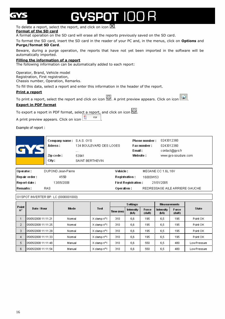
Filling the information of a report The following information can be automatically added to each report:
Operator, Brand, Vehicle model Registration, First registration, Chassis number, Operation, Remarks.
To fill this data, select a report and enter this information in the header of the report.
Print a report
To print a report, select the report and click on icon . A print preview appears. Click on icon .
Export in PDF format
To export a report in PDF format, select a report, and click on icon .
A print preview appears. Click on icon . Example of report :
17
5- PRECAUTIONS AND SERVICING
User training Operators must have an appropriate qualification for the use of the machine in order to get the best from the unit and to
perform a satisfying job (e.g. : car-body repair training).
Preparation of the parts to assemble: It is essential to grind, clean and prepare the part to be welded.
In case of a protection application, first verify that it is conductive by testing a sample.
Single sided gun welding Before repairing a vehicle, check that the car manufacturer authorises the welding process you have chosen.
Use of the under fender arm The maximum pressure is 200 DaN.
X clamp’s nuts circular joints Inside the 2 tightening arms nuts (see description of the clamp), there are 2 circular joints which have to be replaced in case of leaks or every 6 months. These 2 circular joints are necessary to prevent risks of cooling liquid leaks.
These joints have a diameter of d=25, flange=4. During replacement, it is advised to add copper grease on these joints to ease insertion of the arms (copper grease reference : ref. 050440).
Purge of the pneumatic filter Regularly drain the dehumidifier filter placed on the rear side of the unit.
Generator maintenance The maintenance and repair of the current generator must be done by an appointed and GYS trained technician. Any
maintenance operation done by another person will void the warranty. GYS cannot be held responsible for damage or
accidents subsequent to operations performed by people outside of GYS.
Cleaning or replacement of the welding tools Any welding tool is degraded after a certain period of use. All tools must stay clean in order to achieve the best results.
When using the unit in pneumatic clamp mode, check the state of the CAPS electrodes (flat, rounded or bevelled). If this is
not the case, clean them with sandpaper (fine grain) or replace them (see reference on the unit).
For a use in single sided gun mode, it is necessary to check the state of the tools: stars, single point electrode, carbide
electrode, and if they look in bad conditions clean or replace them.
Replacement of the caps/electrodes: ▪ To ensure an efficient welding spot, it is necessary to replace the caps every 200 spots, using the dedicated tool. ▪ Assemble the caps with copper grease (ref. 050440) ▪ A type caps (ref. 049987) ▪ F type caps (ref. 049970) ▪ Bevelled caps (ref. 049994) ▪ Several combinations are possible
Warning: The caps must be perfectly aligned. If
not, check that the electrodes are in line. (cf. replacement of arms p. 18 and 19).
18
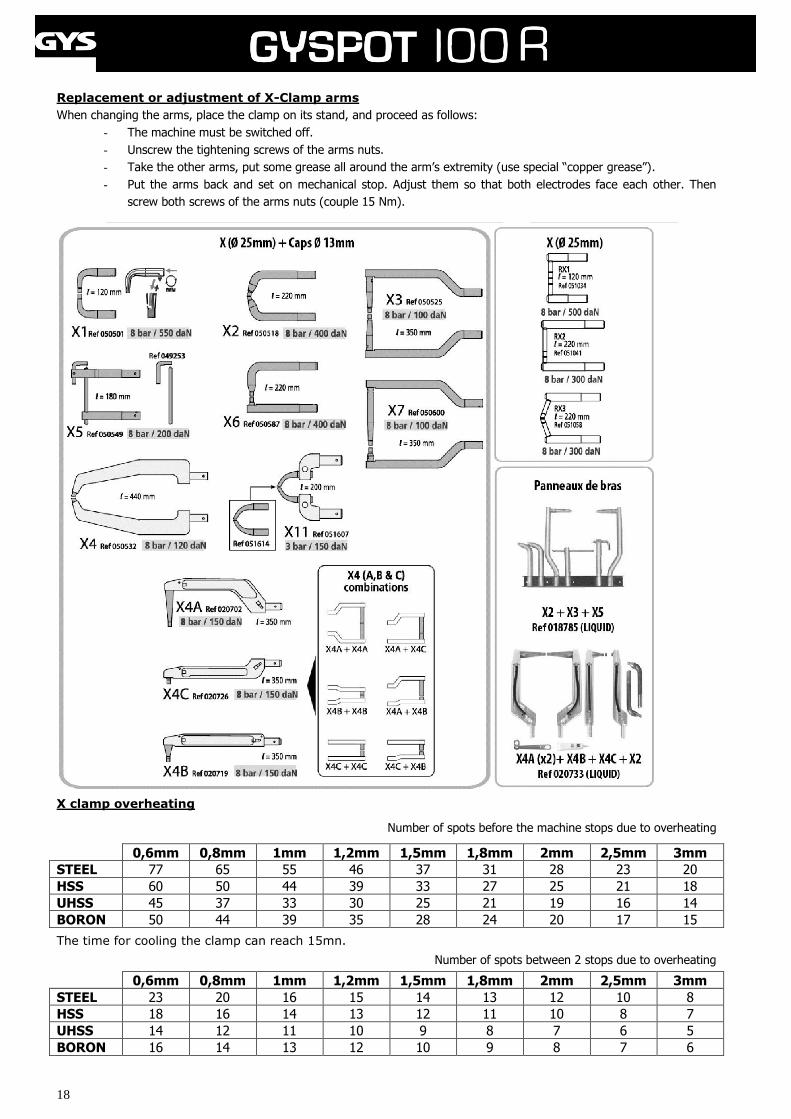
Replacement or adjustment of X-Clamp arms
When changing the arms, place the clamp on its stand, and proceed as follows:
- The machine must be switched off.
- Unscrew the tightening screws of the arms nuts.
- Take the other arms, put some grease all around the arm’s extremity (use special “copper grease”).
- Put the arms back and set on mechanical stop. Adjust them so that both electrodes face each other. Then
screw both screws of the arms nuts (couple 15 Nm).
X clamp overheating
Number of spots before the machine stops due to overheating
0,6mm 0,8mm 1mm 1,2mm 1,5mm 1,8mm 2mm 2,5mm 3mm
STEEL 77 65 55 46 37 31 28 23 20
HSS 60 50 44 39 33 27 25 21 18
UHSS 45 37 33 30 25 21 19 16 14
BORON 50 44 39 35 28 24 20 17 15
The time for cooling the clamp can reach 15mn.
Number of spots between 2 stops due to overheating
0,6mm 0,8mm 1mm 1,2mm 1,5mm 1,8mm 2mm 2,5mm 3mm
STEEL 23 20 16 15 14 13 12 10 8
HSS 18 16 14 13 12 11 10 8 7
UHSS 14 12 11 10 9 8 7 6 5
BORON 16 14 13 12 10 9 8 7 6
19
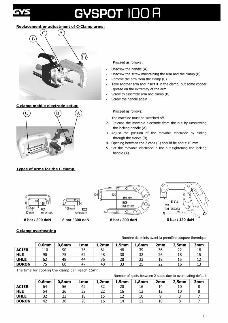
Replacement or adjustment of C-Clamp arms:
-
Proceed as follows :
- Unscrew the handle (A)
- Unscrew the screw maintaining the arm and the clamp (B).
- Remove the arm form the clamp (C).
- Take another arm and insert it in the clamp; put some copper
grease on the extremity of the arm
- Screw to assemble arm and clamp (B)
- Screw the handle again
C clamp mobile electrode setup:
Proceed as follows:
1. The machine must be switched off.
2. Release the movable electrode from the nut by unscrewing
the locking handle (A).
3. Adjust the position of the movable electrode by sliding
through the sleeve (B).
4. Opening between the 2 caps (C) should be about 10 mm.
5. Set the movable electrode in the nut tightening the locking
handle (A).
Types of arms for the C clamp
C clamp overheating
Nombre de points avant la première coupure thermique
0,6mm 0,8mm 1mm 1,2mm 1,5mm 1,8mm 2mm 2,5mm 3mm
ACIER 110 90 76 61 48 39 36 22 18
HLE 90 75 62 48 38 32 26 18 15
UHLE 62 48 44 36 28 23 19 15 12
BORON 75 60 47 40 33 25 22 16 13
The time for cooling the clamp can reach 15mn.
Number of spots between 2 stops due to overheating default
0,6mm 0,8mm 1mm 1,2mm 1,5mm 1,8mm 2mm 2,5mm 3mm
ACIER 64 56 42 32 20 16 14 10 8
HLE 54 36 32 22 16 13 12 10 8
UHLE 32 22 18 15 12 10 9 8 7
BORON 42 36 20 16 14 11 10 8 7
C B A
A
B
C
Ref 052253
8 bar / 120 daN 8 bar / 300 daN 8 bar / 300 daN 8 bar / 300 daN
RC4
20
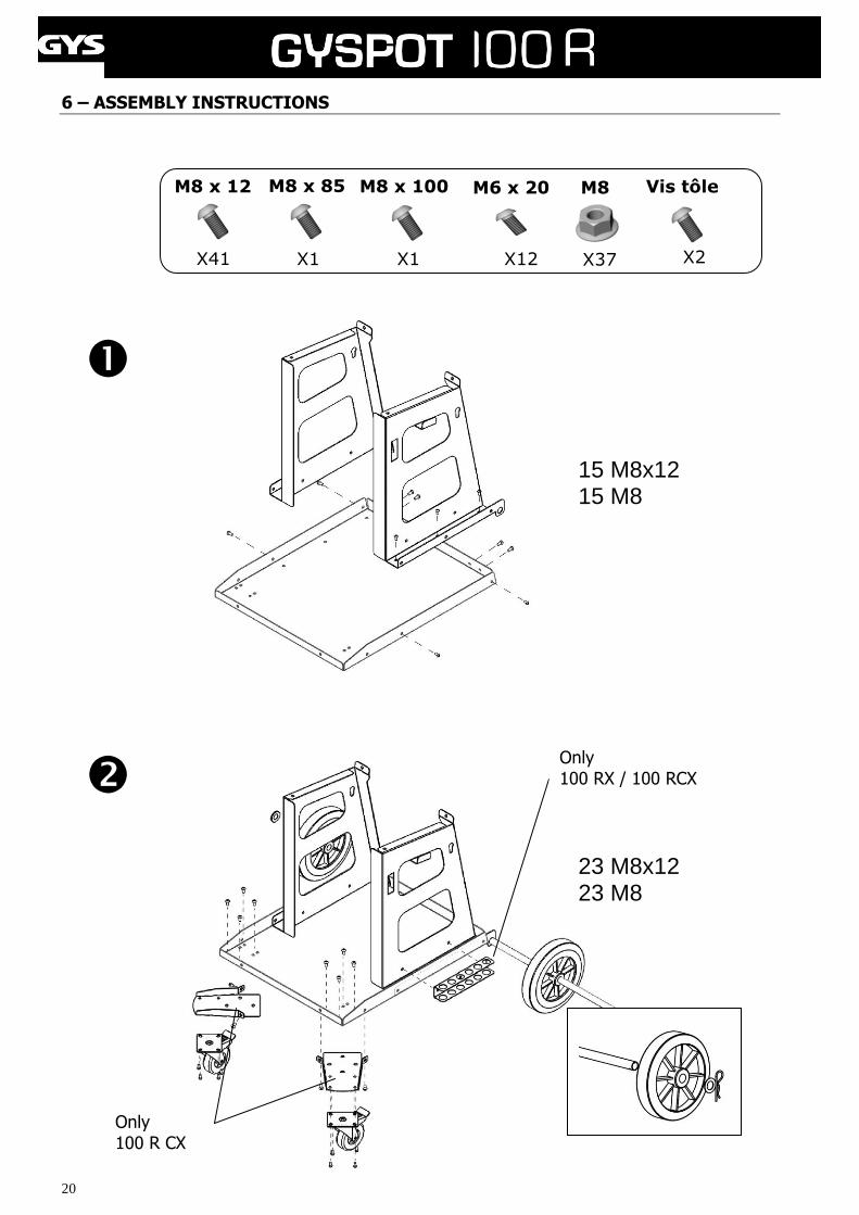
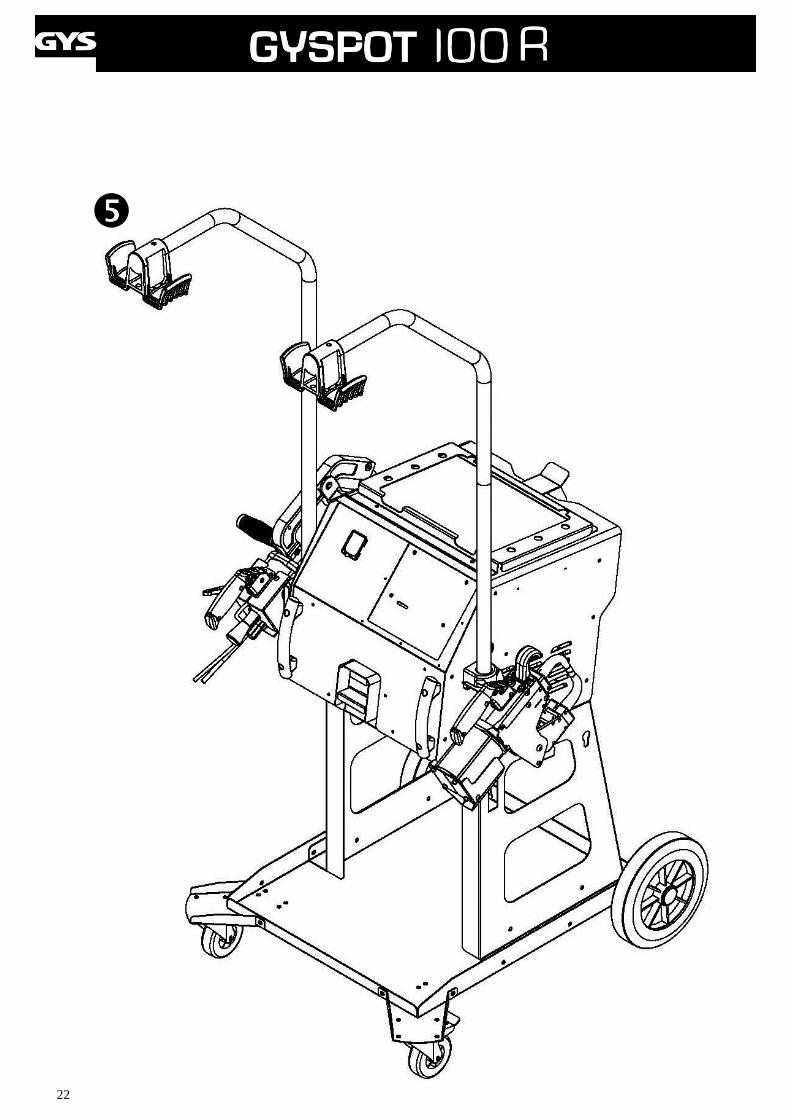
6 – ASSEMBLY INSTRUCTIONS
①
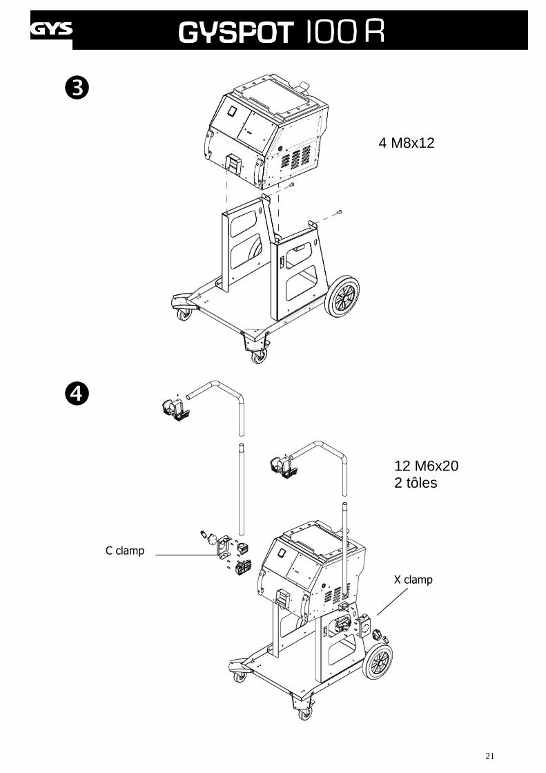
③
M8 x 12
X41
M8
X1
M8 x 85
X37 X1
M8 x 100
X12
M6 x 20
15 M8x12 15 M8
23 M8x12 23 M8
Vis tôle
X2
Only 100 R CX
Only 100 RX / 100 RCX
21
4 M8x12
X clamp
C clamp
12 M6x20 2 tôles
22
23
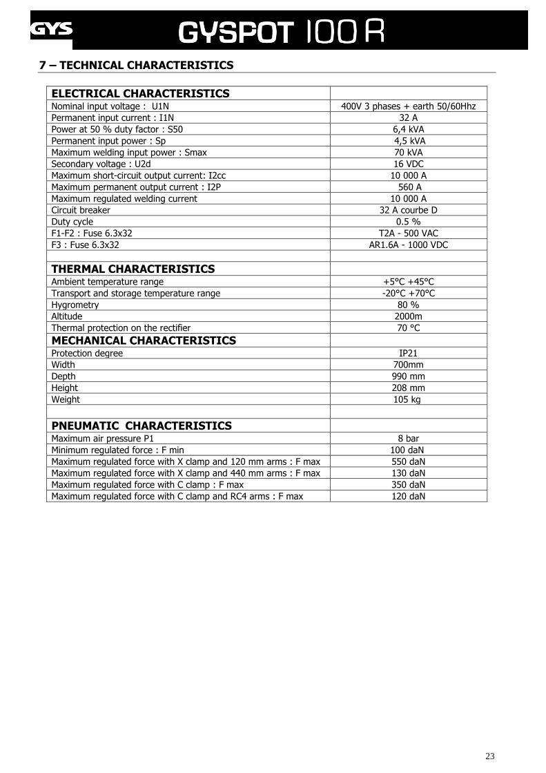
7 – TECHNICAL CHARACTERISTICS
ELECTRICAL CHARACTERISTICS Nominal input voltage : U1N 400V 3 phases + earth 50/60Hhz
Permanent input current : I1N 32 A
Power at 50 % duty factor : S50 6,4 kVA
Permanent input power : Sp 4,5 kVA
Maximum welding input power : Smax 70 kVA
Secondary voltage : U2d 16 VDC
Maximum short-circuit output current: I2cc 10 000 A
Maximum permanent output current : I2P 560 A
Maximum regulated welding current 10 000 A
Circuit breaker 32 A courbe D
Duty cycle 0.5 %
F1-F2 : Fuse 6.3x32 T2A - 500 VAC
F3 : Fuse 6.3x32 AR1.6A - 1000 VDC
THERMAL CHARACTERISTICS Ambient temperature range +5°C +45°C
Transport and storage temperature range -20°C +70°C
Hygrometry 80 %
Altitude 2000m
Thermal protection on the rectifier 70 °C
MECHANICAL CHARACTERISTICS Protection degree IP21
Width 700mm
Depth 990 mm
Height 208 mm
Weight 105 kg
PNEUMATIC CHARACTERISTICS Maximum air pressure P1 8 bar
Minimum regulated force : F min 100 daN
Maximum regulated force with X clamp and 120 mm arms : F max 550 daN
Maximum regulated force with X clamp and 440 mm arms : F max 130 daN
Maximum regulated force with C clamp : F max 350 daN
Maximum regulated force with C clamp and RC4 arms : F max 120 daN
24
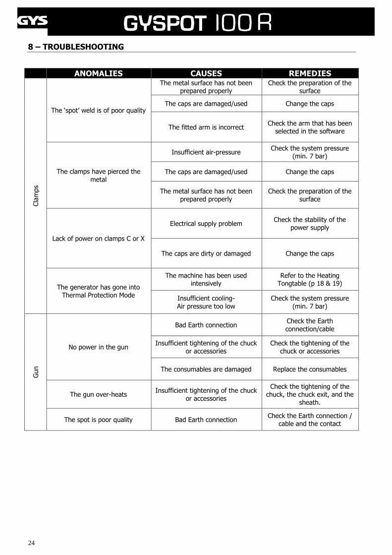
8 – TROUBLESHOOTING
ANOMALIES CAUSES REMEDIES
Cla
mps
The ‘spot’ weld is of poor quality
The metal surface has not been prepared properly
Check the preparation of the surface
The caps are damaged/used Change the caps
The fitted arm is incorrect Check the arm that has been
selected in the software
The clamps have pierced the
metal
Insufficient air-pressure Check the system pressure
(min. 7 bar)
The caps are damaged/used Change the caps
The metal surface has not been
prepared properly
Check the preparation of the
surface
Lack of power on clamps C or X
Electrical supply problem Check the stability of the
power supply
The caps are dirty or damaged Change the caps
The generator has gone into
Thermal Protection Mode
The machine has been used intensively
Refer to the Heating Tongtable (p 18 & 19)
Insufficient cooling-
Air pressure too low
Check the system pressure
(min. 7 bar)
Gun
No power in the gun
Bad Earth connection Check the Earth
connection/cable
Insufficient tightening of the chuck
or accessories
Check the tightening of the
chuck or accessories
The consumables are damaged Replace the consumables
The gun over-heats Insufficient tightening of the chuck
or accessories
Check the tightening of the chuck, the chuck exit, and the
sheath.
The spot is poor quality Bad Earth connection Check the Earth connection /
cable and the contact
25
9 - ICONS
V Volts
A Amps
3 ~ Three-phase power supply
U 1n Nominal input voltage
S p Permanent input power
S max Maximum welding input power
U 20 Alternating current defined unload
I 2 cc Secondary current on short-circuit
IP 21 Protected against rain and moisture. No access to dangerous parts.
Caution! Read the user manual before use
Separate collection required – Do not throw in a domestic waste bin.
Do not use in the open air.
Do not use the product in damp/wet environments. IP21.
Risk of interference and disturbance of electronic medical devices (i.e. pace-makers) when near of the product.
Caution! Strong magnetic field.
People wearing active or passive implants must be informed.
Always wear suitable protective clothing to shield eyes, hands, and skin,
when welding.
10 – DECLARATION OF CONFORMITY
GYS confirm that the product described within this manual conforms to the following directives:
- Low Voltage Directive 2006/95/CE in respect of the harmonized norm EN 62135-1
- Electromagnetic Compatibility Directive EMC 2004/108/CE in respect of the harmonized norm EN62135-2
- Machine Directive 2006/42/EC in respect of the harmonized norm EN 60204-1
26
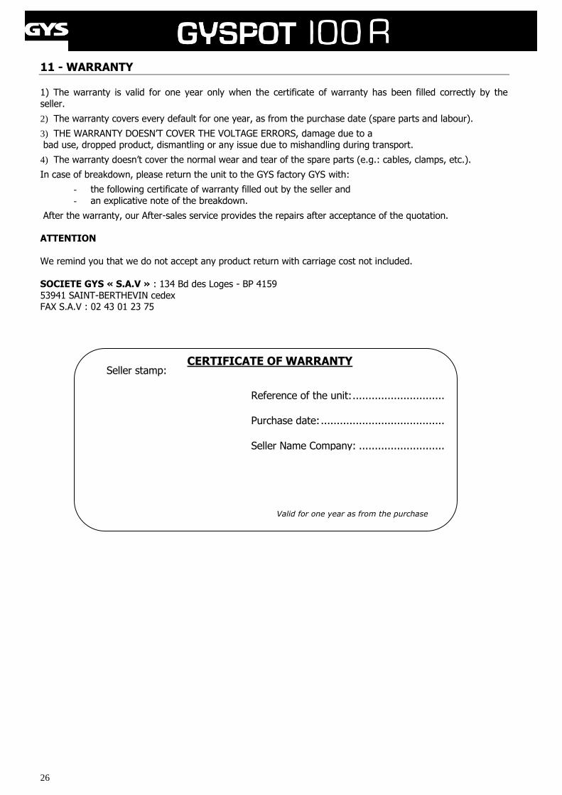
11 - WARRANTY 1) The warranty is valid for one year only when the certificate of warranty has been filled correctly by the
seller.
2) The warranty covers every default for one year, as from the purchase date (spare parts and labour).
3) THE WARRANTY DOESN’T COVER THE VOLTAGE ERRORS, damage due to a bad use, dropped product, dismantling or any issue due to mishandling during transport.
4) The warranty doesn’t cover the normal wear and tear of the spare parts (e.g.: cables, clamps, etc.).
In case of breakdown, please return the unit to the GYS factory GYS with:
- the following certificate of warranty filled out by the seller and
- an explicative note of the breakdown.
After the warranty, our After-sales service provides the repairs after acceptance of the quotation.
ATTENTION
We remind you that we do not accept any product return with carriage cost not included.
SOCIETE GYS « S.A.V » : 134 Bd des Loges - BP 4159
53941 SAINT-BERTHEVIN cedex FAX S.A.V : 02 43 01 23 75
Seller stamp: Reference of the unit: .............................
Purchase date: .......................................
Seller Name Company: ...........................
CERTIFICATE OF WARRANTY
Valid for one year as from the purchase date
27
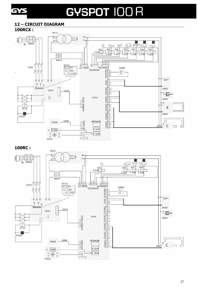
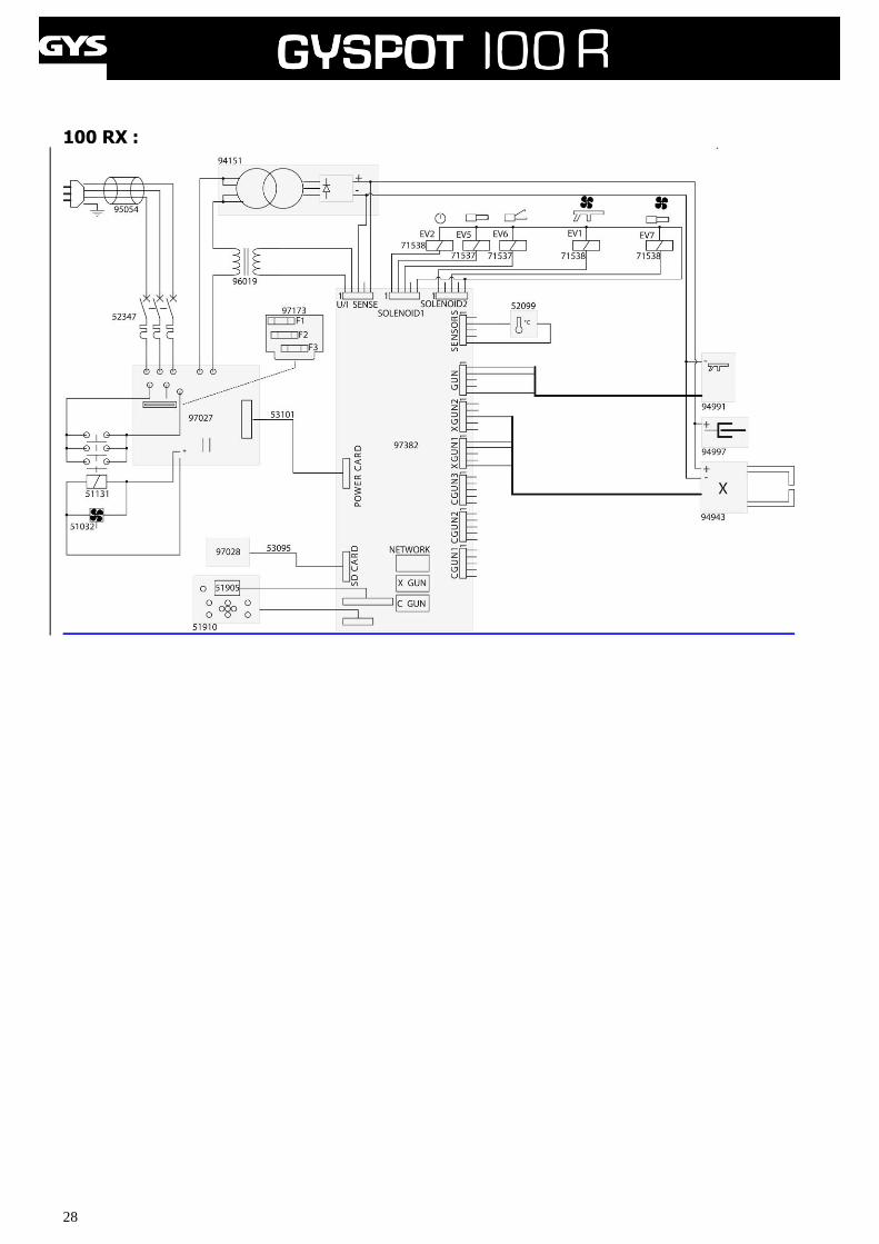
12 – CIRCUIT DIAGRAM
100RCX :
100RC :
28
100 RX :


![Dictdiffer Documentation · ('change','title', ('hellooo','hello'))] Let’s revert the last changes: result=diff(first, second) reverted=revert(result, patched) assert reverted==first](https://img.pdfslide.us/doc/110x75/5fdd11f6e1c9db54394df02d/dictdiffer-documentation-changetitle-hellooohello-letas-revert.jpg)