Embed Size (px)
Citation preview

Page 1 of 37
USER MANUAL
Part 1 – all users
TOUCHCLAVE-LAB AUTOCLAVES
ADVANCED STERILIZING
TECHNOLOGY
LTE Scientific Ltd Greenbridge Lane, Greenfield, Oldham OL3 7EN, England
Tel: +44(0)1457 876221 Fax: +44(0)1457 870131
email: [email protected]
www.lte-scientific.co.uk
FM 23948 0617

Page 2 of 37
NOTICE
Copyright in this document is the property of LTE Scientific Limited (“LTE”). No part of this document may be copied, reproduced, or stored in a retrieval system without the prior
written permission of LTE. The design rights in the products described in this document, including both hardware and software features, are the property of LTE.
Whilst all reasonable precautions have been taken to ensure the accuracy and relevance of
this document, LTE does not accept liability for any errors or omissions, or for any damage or
loss resulting from the use of the information contained herein.
LTE reserves the right to revise or replace any or all of the contents of this document without notice for any reason. Such reasons may include the need to reflect changes to the products
or any of their features or attributes, or to revise the wording of this document.
Issue Date: 06 02 2012
Page 3 of 37
CONTENTS
1. GENERAL 5
1.1 SCOPE OF USER MANUAL 5 1.2 CLASSIFICATION OF USER LEVELS 5 1.3 OVERVIEW OF TOUCHCLAVE LAB AUTOCLAVES 5 1.4 SAFETY PRECAUTIONS 6
2. MAIN FEATURES AND OPTIONS OF THE TOUCHCLAVE LAB RANGE 7
2.1 STANDARD FEATURES 7 2.2 OPTIONAL FEATURES 8 2.3 LOAD CAPACITIES 9 2.4 THE CYCLE SEQUENCE 10 2.5 TYPICAL CYCLES 11
3. THE CONTROL SYSTEM – COMMANDS AND SCREEN TYPES 12
3.1 COMMANDS 12 3.2 PROCESS SCREENS 12 3.3 MENUS 13 3.4 PASSWORD AND BATCH CODE SCREENS 13 3.5 PARAMETER SCREENS 15 3.6 WARNING AND CONFIRMATION SCREENS. 16
4. THE CONTROL SYSTEM - OPERATING THE DOOR 17
4.1 LOCKS 17 4.2 DOOR RESTRICTIONS 18
5. THE CONTROL SYSTEM – RUNNING A CYCLE 20
5.1 STARTING THE CYCLE 20 5.2 CYCLE IN PROGRESS 21 5.3 FAULTS 22 5.4 COOLING OVERRIDE 24 5.5 FINISHING A CYCLE 24 5.6 SAMPLE CYCLE PRINTOUT 25
6. THE CONTROL SYSTEM – OTHER FEATURES 26
6.1 MENU ACCESS TREE FOR SUPERVISORS AND OPERATORS 26 6.2 INITIAL ACCESS 27 6.3 DATA ARCHIVING 27 6.4 VIEW / PRINT LAST CYCLE 28 6.5 SET TIME/DATE 28 6.6 ALARMS 28 6.7 STATUS 28 6.8 CYCLE SETUP 29 6.9 USER SETUP 32 6.10 COOLING OVERRIDE 32
7. CARE AND MAINTENANCE 33
7.1 DOOR SEAL 33 7.2 FITTING A REPLACEMENT SEAL 34

Page 4 of 37
7.3 CLEANING AND DRAINING THE CHAMBER 34 7.4 PRINTERS – INSTRUCTIONS FOR PAPER INSTALLATION 35 7.6 SPARE PARTS – CONSUMABLE 37
Page 5 of 37
1. GENERAL
1.1 Scope of User Manual
This manual provides instructions in the use, set-up and maintenance for the Touchclave Lab
autoclaves manufactured by LTE Scientific Ltd (“LTE”).
All Touchclave Lab autoclaves have rectangular chambers with a choice of capacities – 150,
200, 300, 360 and 450 litres.
There is also a choice of steam supply to the chamber: Internal steam generator (KE models)
Direct steam supply (KS models)
In chamber heating (F models)
Autoclave users should be given training in the actual application environment. This manual is
not intended as a substitute for such training.
1.2 Classification of User Levels
For safety and security, users of Touchclave-R autoclaves are classified in four User Levels:
Operator
Supervisor
Maintenance Engineer
Commissioning Engineer
The User Manual consists of three parts. Part 1 is intended for all User Levels. Part 2 and 3
are reserved for use by Maintenance and Commissioning Engineers, who have a higher User
Level allowing them to perform certain functions which cannot be accessed by Operators and Supervisors.
1.3 Overview Of Touchclave Lab Autoclaves
Autoclaves are steam sterilizers which operate by injecting steam under pressure into the
chamber or vessel where the load to be sterilized has been placed. Steam is generated by water heated either by an internal generator, customer steam supply or within the chamber.
The temperature at which sterilization takes place is pre-programmed, the most common values being 121oC or 134oC, depending on the nature of load to be sterilized.
Control of the Touchclave-Lab autoclave is by means of a touch-screen on the front panel of
the autoclave, using an intuitive hierarchical menu system. Different levels of access are built
into the system by means of passwords indicating the User Level. The menus only display the options available at the User Level of the current user. Thus a user not trained and
authorised for higher-level access cannot accidentally gain access to the more complex functions, such as cycle configuration.
During manufacture, the Touchclave-Lab control system will have been configured to run a standard range of cycles, which can be modified to suit your needs. Therefore the screen
illustrations shown in this manual may not match exactly those displayed on your autoclave, although they will be similar.
Page 6 of 37
1.4 Safety Precautions
Whilst the autoclave has built-in safety devices, their operation may be impaired if the autoclave is not used correctly and in accordance with the instructions. In addition, it is
important to observe the following safety rules at all times: wait until the cycle is complete and the machine is cool before attempting to unload
beware of residual steam in the chamber and hot surfaces when the door is opened
at the end of a cycle
wear an overall or lab coat, high temperature gloves and safety glasses to protect
hands, arms and eyes when loading or unloading the chamber, since the load temperature may be as high as 100oC
when moving the autoclave, for example during installation, remember that its
weight can make it dangerous if not handled carefully
ensure that the earth or ground of the power supply cable is connected to a suitable
protective earth supply, and that the supply lines are correctly fused and isolated
Page 7 of 37
2. MAIN FEATURES AND OPTIONS OF THE TOUCHCLAVE LAB RANGE
2.1 Standard Features
Touchclave KE Model – Internal Steam Generator
If your site does not have a built-in steam supply, the next option is the “Internal Low
Pressure Generator”, which has a second pressure vessel integral to the machine, housing both the heaters and the water supply. The internal heaters generate the steam then the
pressure in both the steam generator and the chamber rise until the set temperature is reached.
Only available on Non – Vacuum models without steam jacket
Touchclave KS Model – Direct Steam Supply
This model requires the customer’s site to have an accessible steam supply for connection to the autoclave. The advantages of this are that the machine has enhanced cycle times due to
the high pressure of most sites’ supply, steam jackets are available and the machine(s) can
be run from a smaller electric power supply.
Touchclave F Model – In Chamber Heating
The ‘F’ model has heaters positioned within the base of the chamber and generates the
steam internally within the chamber.
Touchclave ‘F’ Autoclaves are modular in design, with the various optional features added to
the original machine as required.
General
On KE and KS models the air removal stage is performed by a “Steam Purge” stage where
steam and air are forced to the drain of the machine. After sterilization, cooling is achieved by pumping water around the outside of the chamber. Any drying is achieved using the residual
heat of the chamber. All KE and KS models have water jacket cooling and condensate units fitted as standard and must have a mains water supply and drain available which are not
demineralised and/or deionised.
Page 8 of 37
2.2 Optional Features
There are four main optional performance-enhancing features than can be added to the machine to improve the speed of the cycle and the range of its functionality.
Constant Standby Generator
On KE models, as an alternative to the standard Internal Steam Generator , a high pressure
Constant & Standby Steam Generator may be fitted. This option provides steam on demand and must be fitted if the autoclave is to have either steam jacket or vacuum and air ballast
options installed. It reduces cycle time s and can support both positive and negative pulsing for air removal.
Constant Standby Generators have a high power rating so please ensure you have a sufficient supply available for the autoclave to use.
Steam Jacket
Fitting this option will improve the speed of your cycles. The steam jacket is used throughout
the cycle to reduce the amount of condensation caused by a cool vessel wall. It speeds up
recovery from negative pulses and provides heated insulation for the chamber. If used in conjunction with the Vacuum option, it also provides effective drying of the load at the end of
cycle, expanding the functionality of the machine.
Category 3 Effluent Retention
This provides operator safety by filtering all non-condensable gases through a 0.2 micron filter prior to exhaust, whilst returning liquids to the chamber for sterilization. The HEPA filter
is fitted inside a stainless steel housing that is accessible from the rear of the machine. The
filter should be checked regularly to ensure performance and safety isn’t impaired. If Category 3 Effluent Retention is to be fitted, the machine must be hard-piped to a drain to
allow the water remaining in the chamber at the end of the cycle to be forced down the drain.
Vacuum and Air Ballast
The Vacuum and Air Ballast option adds functionality to the start and end of the cycle, and expands the variety of loads that the machine can deal with. The vacuum can be used for air
removal at the start of the cycle as a ‘Pre-Vacuum” stage’ , where a vacuum is drawn in the chamber to a set pressure. With Negative pulsing, steam is injected into the chamber to
raise the pressure up to a set point, before the vacuum pump takes the pressure back down
to the low set point again. This is repeated for a number of “pulses” until sufficient air has been removed from the load.
In the ‘Post – vacuum’ stage at the end of sterilizing the air ballast may be used to maintain a pressure in the chamber while it is being cooled rapidly. This prevents liquids from boiling
over and sealed loads from rupturing. Then if required a vacuum is drawn in the chamber to dry the load.
If the Vacuum and Air Ballast option is to be fitted, a drain and mains water supply must be available.
Water Jacket
This feature is fitted as standard to KE and KS models and is available on option on ‘F’ models. The purpose of this feature is to speed up the cooling stage of the cycle
Page 9 of 37
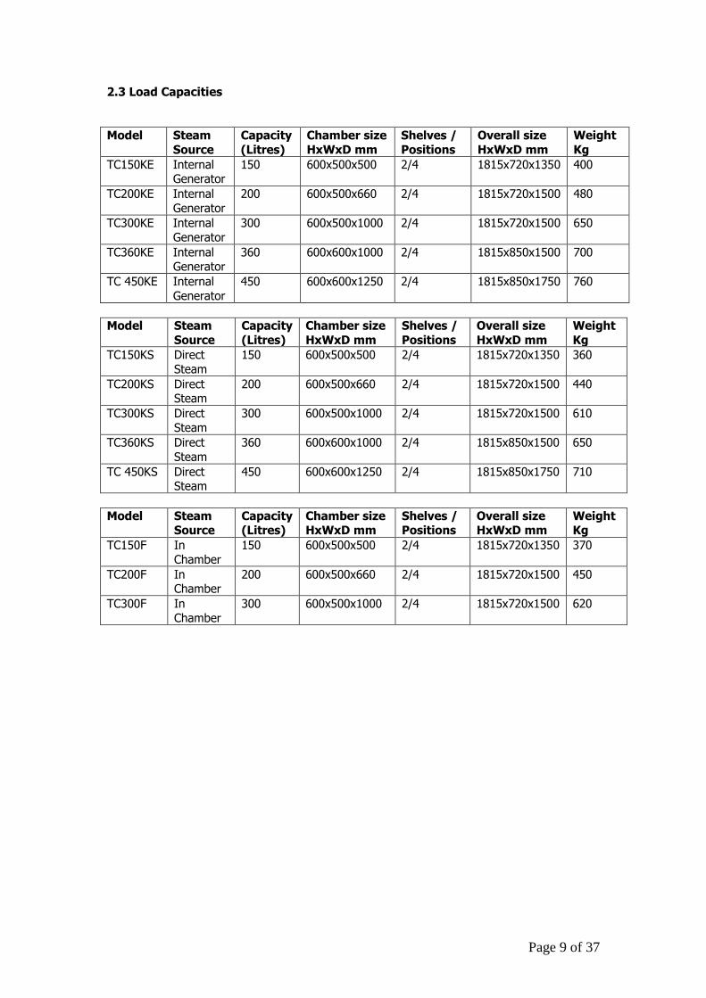
2.3 Load Capacities
Model Steam
Source
Capacity
(Litres)
Chamber size
HxWxD mm
Shelves /
Positions
Overall size
HxWxD mm
Weight
Kg
TC150KE Internal Generator
150 600x500x500 2/4 1815x720x1350 400
TC200KE Internal
Generator
200 600x500x660 2/4 1815x720x1500 480
TC300KE Internal
Generator
300 600x500x1000 2/4 1815x720x1500 650
TC360KE Internal Generator
360 600x600x1000 2/4 1815x850x1500 700
TC 450KE Internal
Generator
450 600x600x1250 2/4 1815x850x1750 760
Model Steam
Source
Capacity
(Litres)
Chamber size
HxWxD mm
Shelves /
Positions
Overall size
HxWxD mm
Weight
Kg
TC150KS Direct
Steam
150 600x500x500 2/4 1815x720x1350 360
TC200KS Direct Steam
200 600x500x660 2/4 1815x720x1500 440
TC300KS Direct
Steam
300 600x500x1000 2/4 1815x720x1500 610
TC360KS Direct
Steam 360 600x600x1000 2/4 1815x850x1500 650
TC 450KS Direct Steam
450 600x600x1250 2/4 1815x850x1750 710
Model Steam Source
Capacity (Litres)
Chamber size HxWxD mm
Shelves / Positions
Overall size HxWxD mm
Weight Kg
TC150F In
Chamber
150 600x500x500 2/4 1815x720x1350 370
TC200F In Chamber
200 600x500x660 2/4 1815x720x1500 450
TC300F In
Chamber
300 600x500x1000 2/4 1815x720x1500 620
Page 10 of 37
2.4 The Cycle Sequence
The main stages of the Sterilising cycle are as follows:
Door Sealing
When the door has been closed you can either press “Lock” or select the cycle you wish to run and press start. This will cause the door to lock and seal automatically.
Air Removal
If your machine does not have the Vacuum and Air ballast option fitted, “Steam Purge” is the stage used for removing air from the chamber. With a Direct Steam or Constant Standby
Generator equipped machine, a valve is opened and steam injected into the chamber. With a
standard internal generator, the heaters are switched on and the steam generated as required. The steam is allowed to escape through a valve at the rear of the chamber, and in
so doing carries out the air present in the chamber.
For loads that are more likely to trap air (e.g. plastic discard) then a Vacuum system is
recommended. The stages of air removal in this case are “Pre-Vacuum” and “Negative Pulsing”. The vacuum has superior air removal, but may increase the overall length of the
cycle. This option is only available on machines fitted with a Constant Standby Generator.
Both Direct Steam and Constant Standby Generator equipped machines are also capable of positive pulsing. In this stage the pressure in the chamber is increased up to a high set point,
usually 2000mBA (1 Bar on the gauge). The pressure is then allowed to escape through the
vent valve of the machine, taking any air with it, until a low set point of 1200 mBar is achieved. This counts as 1 positive pulse, and the number of positive pulses can be set to any
number required until sufficient air is concluded to have been removed from the chamber and load.
Heating up
The autoclave raises its pressure and temperature to the set sterilizing values specified for
the cycle. The time taken by this stage depends on the level of the set points are and the contents of the load to be sterilized. When the load probe (which should be placed either in
the load to be sterilized or in a simulated load device) reports that the sterilizing temperature
has been reached the stage will be complete.
Sterilizing
During this stage, the cycle achieves its objective. Whilst the sterilizing temperature can be
set for any given cycle at any value between 1050C and 1360C, the values most commonly chosen are 1210C or 1340C, depending on the nature of load to be sterilized (see below). If
the printer is fitted, its output during this stage will provide proof that the load has been
sterilised. The length of time for sterilization can also be selected by the user, up to a maximum of 30 minutes.
Page 11 of 37
Cooling
Once the sterilizing time is complete we enter the “Cooling” stage. If Vacuum and Air Ballast is fitted then the machine can be configured to drop the pressure
quite rapidly and pull the chamber down into a vacuum condition. This can only be done with certain loads – sealed bottles could explode and liquids boil over. So it is important you
choose the correct cycle to run for the load you are sterilizing.
If a water jacket is fitted, it can either activate instantly or be configured to wait until the
pressure in the chamber has dropped naturally before starting, in order to prevent the contents of the chamber losing pressure too rapidly.
Drying
Drying is more efficient with the Vacuum and Air Ballast option and an active steam jacket
fitted to the machine. The pressure is dropped, where applicable, for a set amount of time so that the load can be vacuum dried as much as possible. With a steam jacket fitted, there is a
significant reduction in moisture inside the vessel prior to the drying stage. As this stage relies on the residual heat inside the vessel to dry the load, there can be too much moisture
present on the load for effective drying if there is no steam jacket fitted.
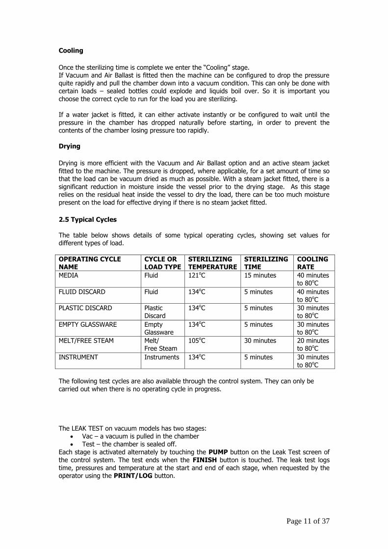
2.5 Typical Cycles
The table below shows details of some typical operating cycles, showing set values for different types of load.
OPERATING CYCLE NAME
CYCLE OR LOAD TYPE
STERILIZING TEMPERATURE
STERILIZING TIME
COOLING RATE
MEDIA Fluid 121oC 15 minutes 40 minutes to 80oC
FLUID DISCARD Fluid 134oC 5 minutes 40 minutes to 80oC
PLASTIC DISCARD Plastic Discard
134oC 5 minutes 30 minutes to 80oC
EMPTY GLASSWARE Empty Glassware
134oC 5 minutes 30 minutes to 80oC
MELT/FREE STEAM Melt/ Free Steam
105oC 30 minutes 20 minutes to 80oC
INSTRUMENT Instruments 134oC 5 minutes 30 minutes
to 80oC
The following test cycles are also available through the control system. They can only be
carried out when there is no operating cycle in progress.
The LEAK TEST on vacuum models has two stages: Vac – a vacuum is pulled in the chamber
Test – the chamber is sealed off.
Each stage is activated alternately by touching the PUMP button on the Leak Test screen of
the control system. The test ends when the FINISH button is touched. The leak test logs
time, pressures and temperature at the start and end of each stage, when requested by the operator using the PRINT/LOG button.
Page 12 of 37
3. THE CONTROL SYSTEM – COMMANDS AND SCREEN TYPES In this section, features and techniques for accessing the various capabilities of the Autoclave and information displayed about the autoclave’s state are described.
3.1 Commands
The screens have been designed to have a common and consistent set of displays and
commands. The standard buttons and their meanings are:
This button will appear on the top right of the screen. Return to Previous screen.
These Browse buttons will appear where there are multiple sets of screens to browse between.
These buttons move Up and Down menu options being displayed
This button is to select or Enter the currently highlighted option.
These buttons move back and forth between parameter values in a set.
These buttons select different options when a parameter value is a multiple-choice option.
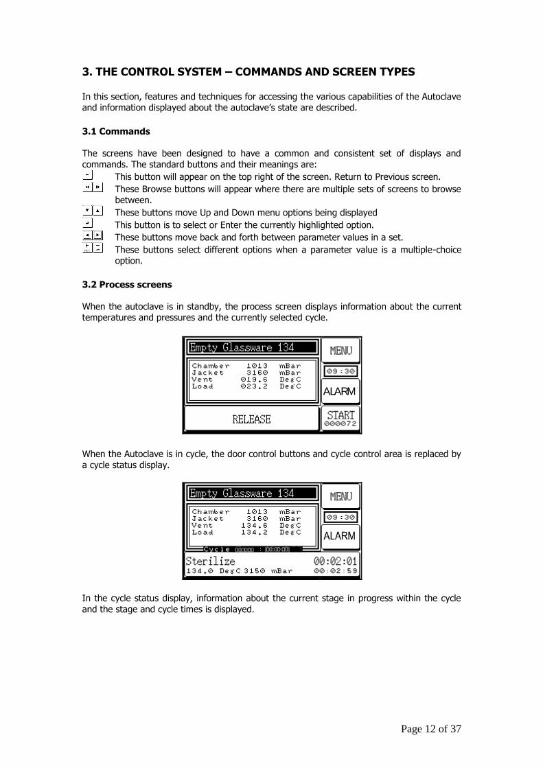
3.2 Process screens
When the autoclave is in standby, the process screen displays information about the current temperatures and pressures and the currently selected cycle.
ALARM
When the Autoclave is in cycle, the door control buttons and cycle control area is replaced by
a cycle status display.
In the cycle status display, information about the current stage in progress within the cycle
and the stage and cycle times is displayed.
Page 13 of 37
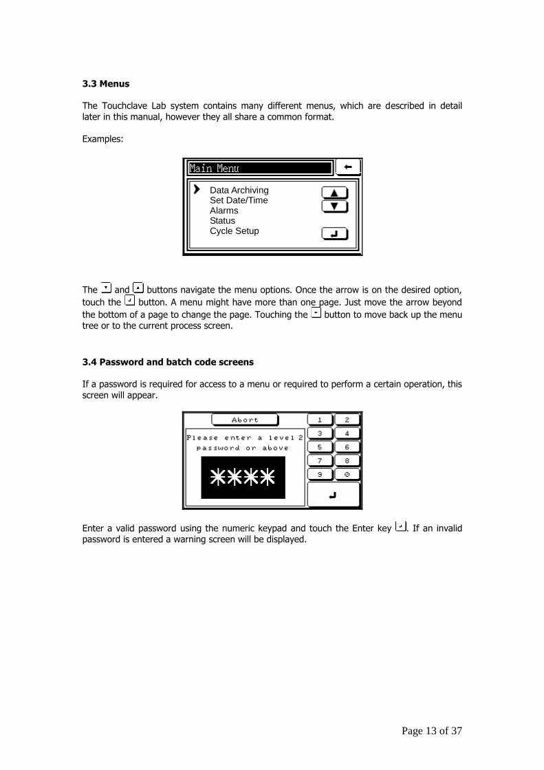
3.3 Menus
The Touchclave Lab system contains many different menus, which are described in detail
later in this manual, however they all share a common format.
Examples:
Data ArchivingSet Date/TimeAlarmsStatusCycle Setup
The and buttons navigate the menu options. Once the arrow is on the desired option,
touch the button. A menu might have more than one page. Just move the arrow beyond
the bottom of a page to change the page. Touching the button to move back up the menu tree or to the current process screen.
3.4 Password and batch code screens
If a password is required for access to a menu or required to perform a certain operation, this
screen will appear.
Enter a valid password using the numeric keypad and touch the Enter key . If an invalid password is entered a warning screen will be displayed.
Page 14 of 37
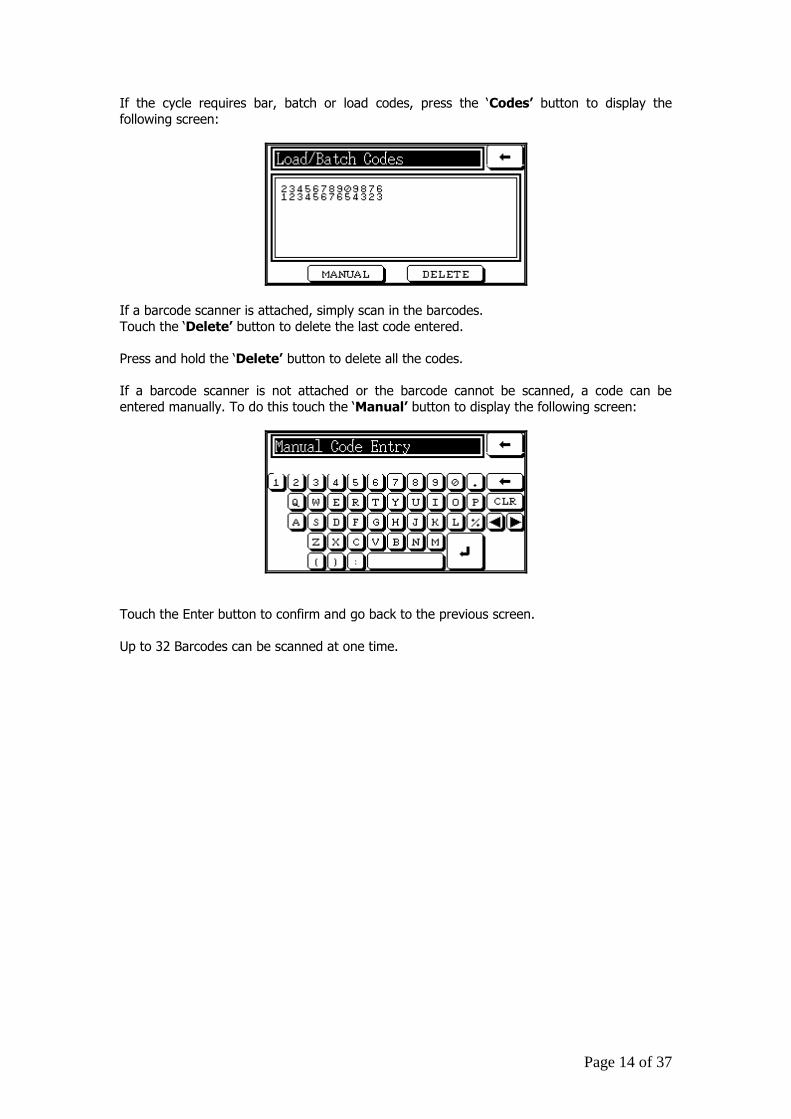
If the cycle requires bar, batch or load codes, press the ‘Codes’ button to display the
following screen:
If a barcode scanner is attached, simply scan in the barcodes.
Touch the ‘Delete’ button to delete the last code entered.
Press and hold the ‘Delete’ button to delete all the codes.
If a barcode scanner is not attached or the barcode cannot be scanned, a code can be
entered manually. To do this touch the ‘Manual’ button to display the following screen:
Touch the Enter button to confirm and go back to the previous screen.
Up to 32 Barcodes can be scanned at one time.
Page 15 of 37
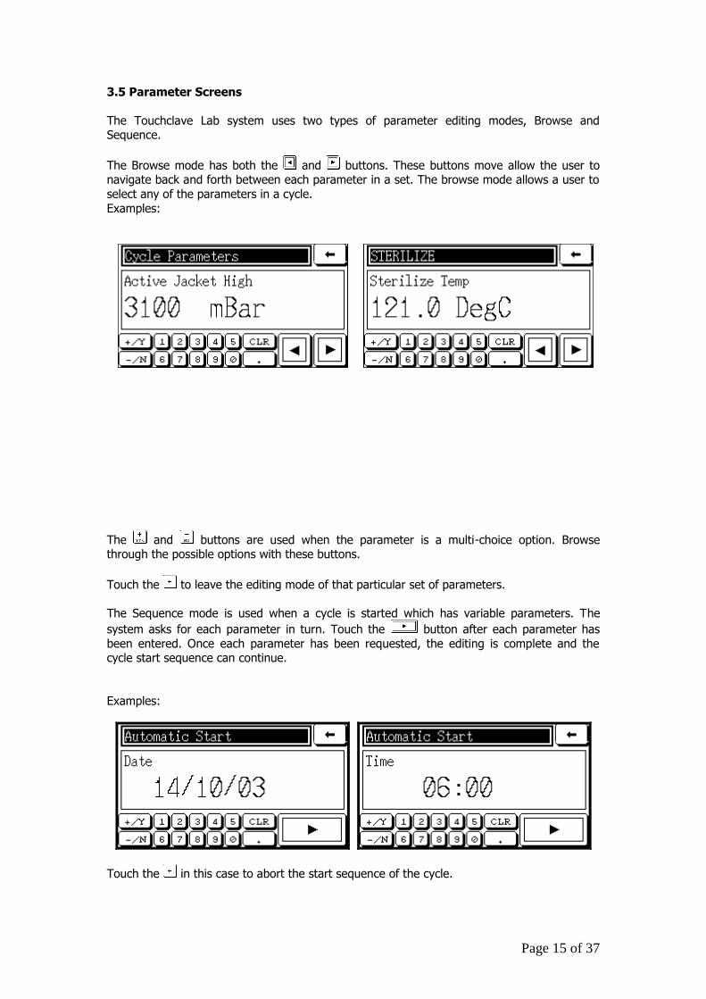
3.5 Parameter Screens
The Touchclave Lab system uses two types of parameter editing modes, Browse and Sequence.
The Browse mode has both the and buttons. These buttons move allow the user to navigate back and forth between each parameter in a set. The browse mode allows a user to
select any of the parameters in a cycle.
Examples:
The and buttons are used when the parameter is a multi-choice option. Browse through the possible options with these buttons.
Touch the to leave the editing mode of that particular set of parameters.
The Sequence mode is used when a cycle is started which has variable parameters. The
system asks for each parameter in turn. Touch the button after each parameter has
been entered. Once each parameter has been requested, the editing is complete and the cycle start sequence can continue.
Examples:
Touch the in this case to abort the start sequence of the cycle.
Page 16 of 37
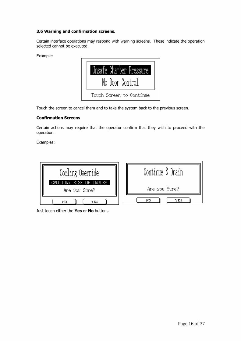
3.6 Warning and confirmation screens.
Certain interface operations may respond with warning screens. These indicate the operation selected cannot be executed.
Example:
Touch the screen to cancel them and to take the system back to the previous screen.
Confirmation Screens
Certain actions may require that the operator confirm that they wish to proceed with the
operation.
Examples:
Just touch either the Yes or No buttons.
Page 17 of 37
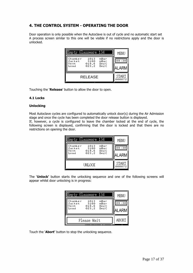
4. THE CONTROL SYSTEM - OPERATING THE DOOR Door operation is only possible when the Autoclave is out of cycle and no automatic start set A process screen similar to this one will be visible if no restrictions apply and the door is
unlocked.
RELEASE
Touching the ‘Release’ button to allow the door to open.
4.1 Locks
Unlocking
Most Autoclave cycles are configured to automatically unlock door(s) during the Air Admission stage and once the cycle has been completed the door release button is displayed.
If, however, a cycle is configured to leave the chamber locked at the end of cycle, the following screen is displayed, confirming that the door is locked and that there are no
restrictions on opening the door.
The ‘Unlock’ button starts the unlocking sequence and one of the following screens will appear whilst door unlocking is in progress:
Touch the ‘Abort’ button to stop the unlocking sequence.
Page 18 of 37
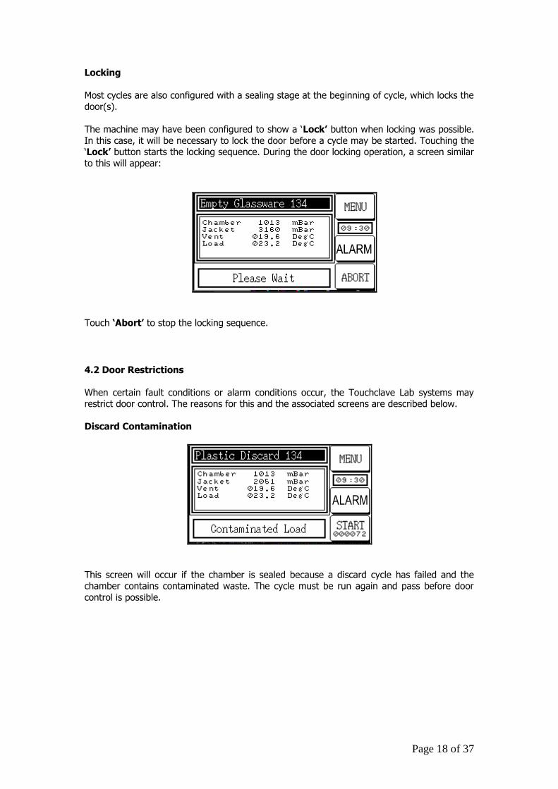
Locking
Most cycles are also configured with a sealing stage at the beginning of cycle, which locks the
door(s).
The machine may have been configured to show a ‘Lock’ button when locking was possible.
In this case, it will be necessary to lock the door before a cycle may be started. Touching the ‘Lock’ button starts the locking sequence. During the door locking operation, a screen similar
to this will appear:
Touch ‘Abort’ to stop the locking sequence.
4.2 Door Restrictions
When certain fault conditions or alarm conditions occur, the Touchclave Lab systems may restrict door control. The reasons for this and the associated screens are described below.
Discard Contamination
This screen will occur if the chamber is sealed because a discard cycle has failed and the chamber contains contaminated waste. The cycle must be run again and pass before door
control is possible.
Page 19 of 37
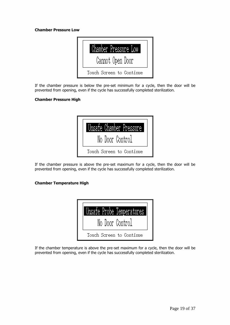
Chamber Pressure Low
If the chamber pressure is below the pre-set minimum for a cycle, then the door will be prevented from opening, even if the cycle has successfully completed sterilization.
Chamber Pressure High
If the chamber pressure is above the pre-set maximum for a cycle, then the door will be prevented from opening, even if the cycle has successfully completed sterilization.
Chamber Temperature High
If the chamber temperature is above the pre-set maximum for a cycle, then the door will be
prevented from opening, even if the cycle has successfully completed sterilization.
Page 20 of 37
5. THE CONTROL SYSTEM – RUNNING A CYCLE
5.1 Starting the cycle
After the load has been placed in the chamber, the batch code entered (if required), and the
door closed, the autoclave is ready to start a cycle. By touching the START button on the standby Process Screen (see section 4.2 above), a sequence of screens is activated to prepare
the autoclave to start a cycle. The operator is first asked to nominate the type of cycle which is to be run. Some cycles may be set up to require a password to be entered. At the end of the
sequence, a Cycle Start screen similar to the one below appears, allowing the operator to choose between an immediate start by touching the START button, or a delayed automatic
start by touching the AUTO button.
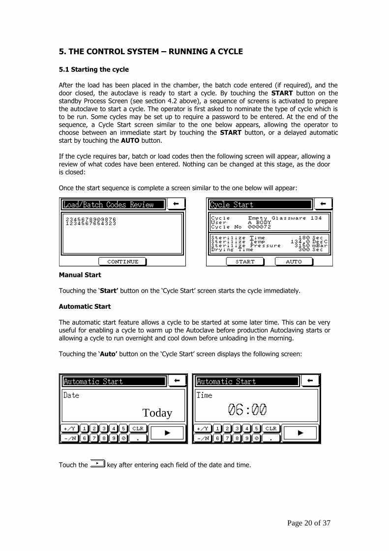
If the cycle requires bar, batch or load codes then the following screen will appear, allowing a
review of what codes have been entered. Nothing can be changed at this stage, as the door is closed:
Once the start sequence is complete a screen similar to the one below will appear:
Manual Start
Touching the ‘Start’ button on the ‘Cycle Start’ screen starts the cycle immediately.
Automatic Start
The automatic start feature allows a cycle to be started at some later time. This can be very useful for enabling a cycle to warm up the Autoclave before production Autoclaving starts or
allowing a cycle to run overnight and cool down before unloading in the morning.
Touching the ‘Auto’ button on the ‘Cycle Start’ screen displays the following screen:
Touch the key after entering each field of the date and time.
Today
Page 21 of 37
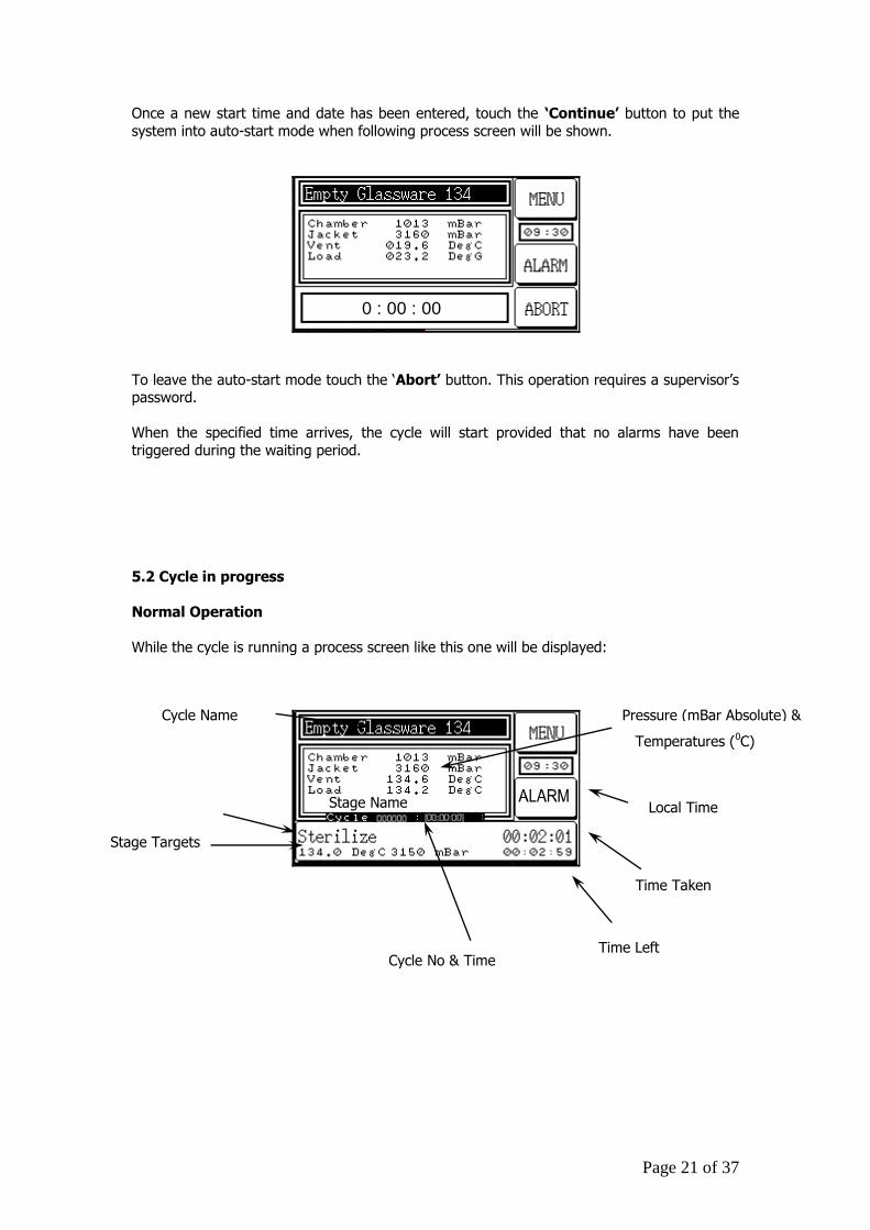
Once a new start time and date has been entered, touch the ‘Continue’ button to put the
system into auto-start mode when following process screen will be shown.
0 : 00 : 00
To leave the auto-start mode touch the ‘Abort’ button. This operation requires a supervisor’s password.
When the specified time arrives, the cycle will start provided that no alarms have been
triggered during the waiting period.
5.2 Cycle in progress
Normal Operation
While the cycle is running a process screen like this one will be displayed:
Local Time
Temperatures (0C)
Stage Name
Stage Targets
Time Taken
Cycle No & Time Time Left
Pressure (mBar Absolute) & Cycle Name
Page 22 of 37
Manual Leak Test
During the ‘Manual Leak Test’ stage the following screen will be visible:
PUMPManual Leak test
During this stage the operator can alternate between two sub-stages with the ‘Pump
On/Off’ Button. Vac – A Vacuum is pulled in the chamber
Test – The chamber is totally sealed off.
The stage ends when the ‘Finish’ Button is pressed.
The stage logs time, pressures and temperature at the start and end of these sub-stages and
when manually requested by the ‘Print Log’ button.
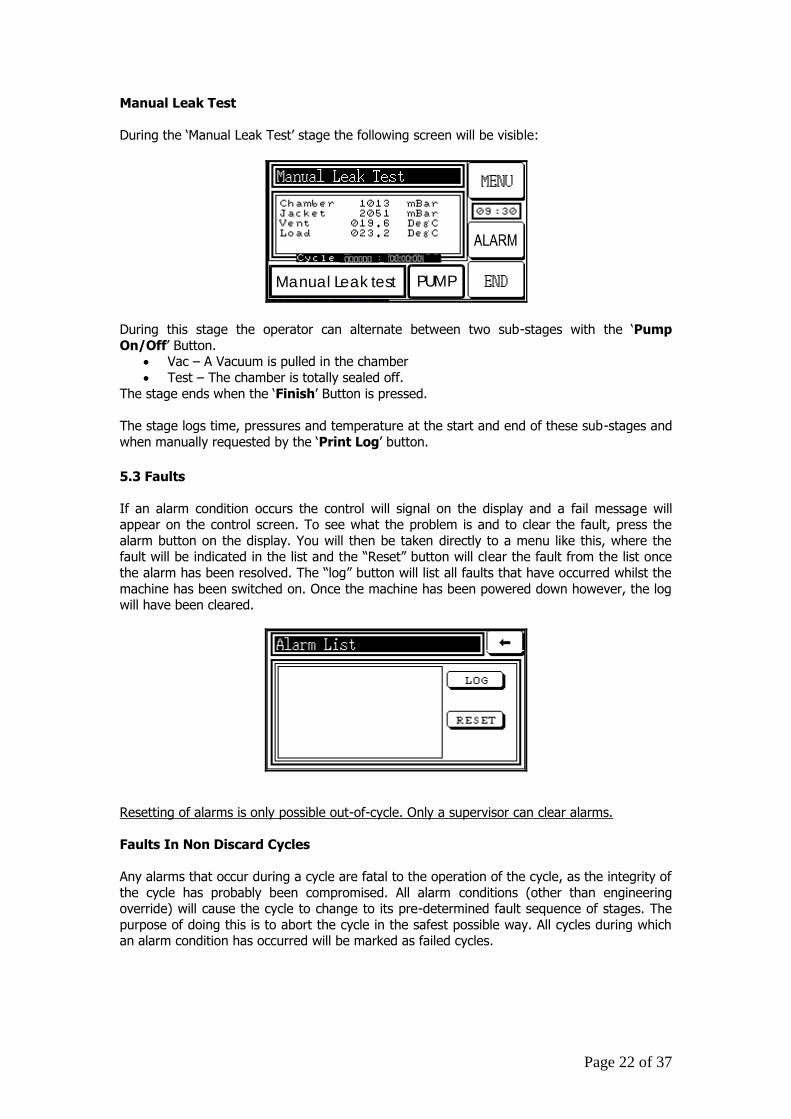
5.3 Faults
If an alarm condition occurs the control will signal on the display and a fail message will appear on the control screen. To see what the problem is and to clear the fault, press the
alarm button on the display. You will then be taken directly to a menu like this, where the fault will be indicated in the list and the “Reset” button will clear the fault from the list once
the alarm has been resolved. The “log” button will list all faults that have occurred whilst the
machine has been switched on. Once the machine has been powered down however, the log will have been cleared.
Resetting of alarms is only possible out-of-cycle. Only a supervisor can clear alarms.
Faults In Non Discard Cycles
Any alarms that occur during a cycle are fatal to the operation of the cycle, as the integrity of
the cycle has probably been compromised. All alarm conditions (other than engineering override) will cause the cycle to change to its pre-determined fault sequence of stages. The
purpose of doing this is to abort the cycle in the safest possible way. All cycles during which an alarm condition has occurred will be marked as failed cycles.
Page 23 of 37
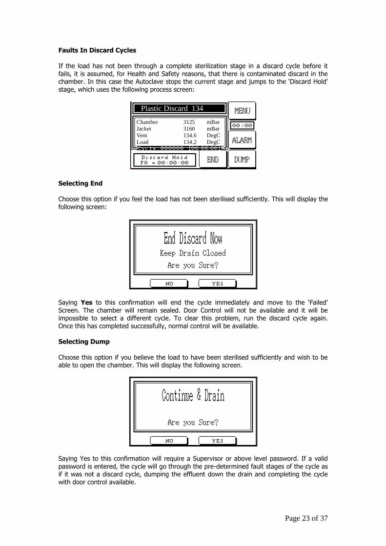
Faults In Discard Cycles
If the load has not been through a complete sterilization stage in a discard cycle before it
fails, it is assumed, for Health and Safety reasons, that there is contaminated discard in the chamber. In this case the Autoclave stops the current stage and jumps to the ‘Discard Hold’
stage, which uses the following process screen:
Chamber 3125 mBar
Jacket 3160 mBar
Vent 134.6 DegC
Load 134.2 DegC
Plastic Discard 134
Selecting End
Choose this option if you feel the load has not been sterilised sufficiently. This will display the
following screen:
Saying Yes to this confirmation will end the cycle immediately and move to the ‘Failed’
Screen. The chamber will remain sealed. Door Control will not be available and it will be
impossible to select a different cycle. To clear this problem, run the discard cycle again. Once this has completed successfully, normal control will be available.
Selecting Dump
Choose this option if you believe the load to have been sterilised sufficiently and wish to be able to open the chamber. This will display the following screen.
Saying Yes to this confirmation will require a Supervisor or above level password. If a valid
password is entered, the cycle will go through the pre-determined fault stages of the cycle as if it was not a discard cycle, dumping the effluent down the drain and completing the cycle
with door control available.
Page 24 of 37
5.4 Cooling Override
It is possible to shorten the overall cycle time by accessing the Cooling Override through the menu, which can bring the cooling stage to an end after the temperature has reduced to below
100oC (rather than the normal 80oC). If the Cooling Override is used, care must be taken to ensure that the temperature inside the chamber is safe for the load when it is suddenly exposed
to ambient air temperature. It is recommended that the user draws up a procedure for use of
the Cooling Override function, and that its availability is limited to supervisors.
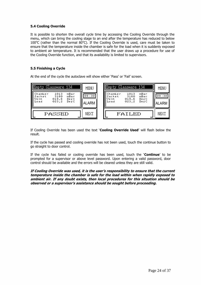
5.5 Finishing a Cycle
At the end of the cycle the autoclave will show either ‘Pass’ or ‘Fail’ screen.
If Cooling Override has been used the text ‘Cooling Override Used’ will flash below the result.
If the cycle has passed and cooling override has not been used, touch the continue button to
go straight to door control.
If the cycle has failed or cooling override has been used, touch the ‘Continue’ to be
prompted for a supervisor or above level password. Upon entering a valid password, door control should be available and the errors will be cleared unless they are still valid.
If Cooling Override was used, it is the user’s responsibility to ensure that the current temperature inside the chamber is safe for the load within when rapidly exposed to ambient air. If any doubt exists, then local procedures for this situation should be observed or a supervisor’s assistance should be sought before proceeding.
Page 25 of 37
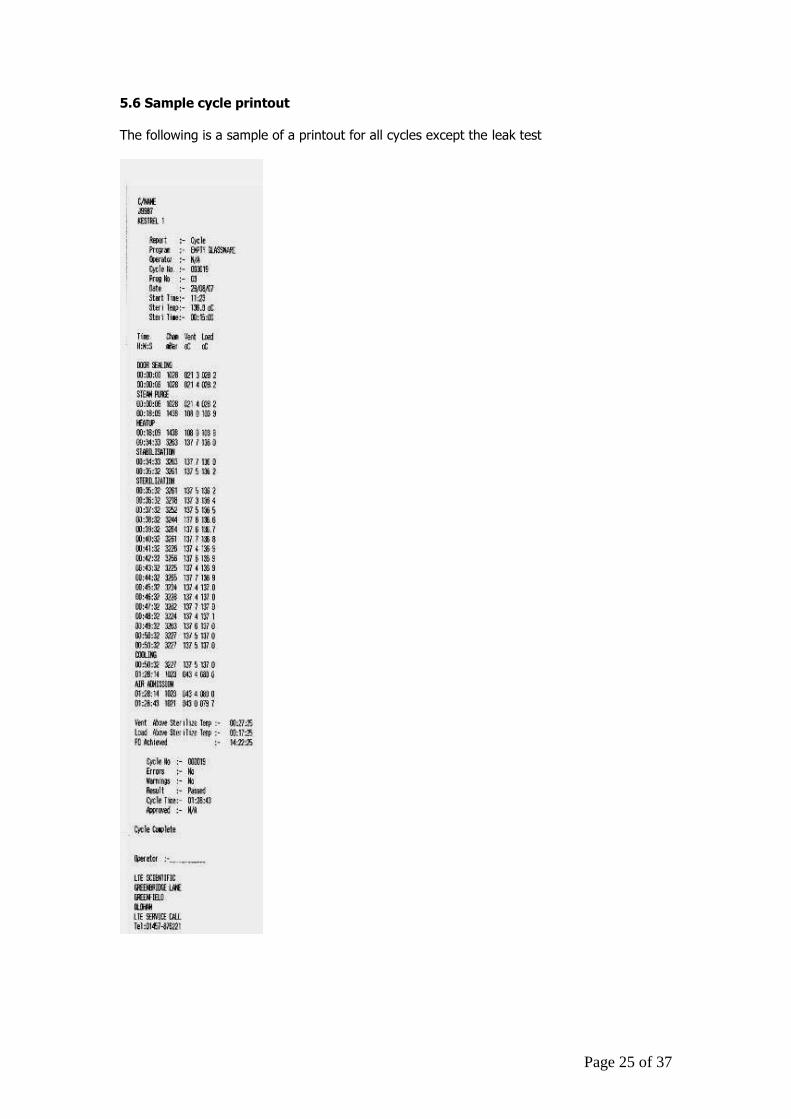
5.6 Sample cycle printout
The following is a sample of a printout for all cycles except the leak test
Page 26 of 37
6. THE CONTROL SYSTEM – OTHER FEATURES
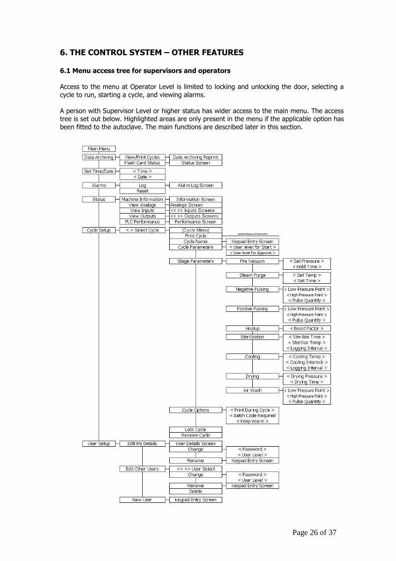
6.1 Menu access tree for supervisors and operators
Access to the menu at Operator Level is limited to locking and unlocking the door, selecting a
cycle to run, starting a cycle, and viewing alarms.
A person with Supervisor Level or higher status has wider access to the main menu. The access tree is set out below. Highlighted areas are only present in the menu if the applicable option has
been fitted to the autoclave. The main functions are described later in this section.
Page 27 of 37
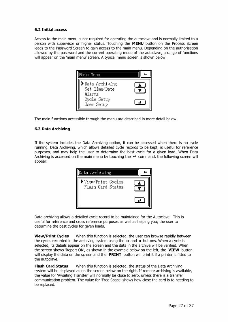
6.2 Initial access
Access to the main menu is not required for operating the autoclave and is normally limited to a person with supervisor or higher status. Touching the MENU button on the Process Screen
leads to the Password Screen to gain access to the main menu. Depending on the authorisation allowed by the password and the current operating mode of the autoclave, a range of functions
will appear on the ‘main menu’ screen. A typical menu screen is shown below.
The main functions accessible through the menu are described in more detail below.
6.3 Data Archiving
If the system includes the Data Archiving option, it can be accessed when there is no cycle
running. Data Archiving, which allows detailed cycle records to be kept, is useful for reference purposes, and may help the user to determine the best cycle for a given load. When Data
Archiving is accessed on the main menu by touching the command, the following screen will
appear:
Data archiving allows a detailed cycle record to be maintained for the Autoclave. This is
useful for reference and cross reference purposes as well as helping you; the user to determine the best cycles for given loads.
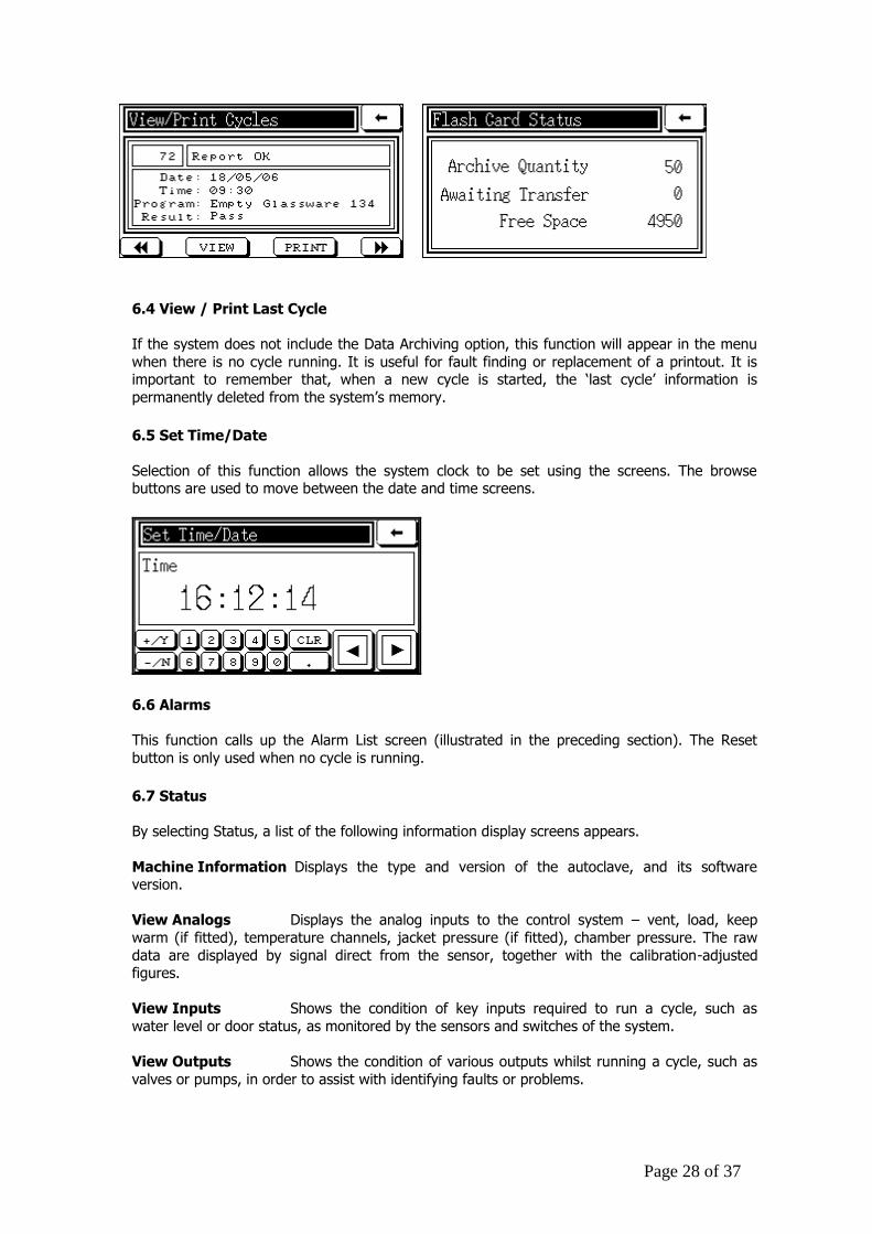
View/Print Cycles When this function is selected, the user can browse rapidly between
the cycles recorded in the archiving system using the and buttons. When a cycle is selected, its details appear on the screen and the data in the archive will be verified. When
the screen shows ‘Report OK’, as shown in the example below on the left, the VIEW button will display the data on the screen and the PRINT button will print it if a printer is fitted to
the autoclave.
Flash Card Status When this function is selected, the status of the Data Archiving system will be displayed as on the screen below on the right. If remote archiving is available,
the value for ‘Awaiting Transfer’ will normally be close to zero, unless there is a transfer communication problem. The value for ‘Free Space’ shows how close the card is to needing to
be replaced.
Page 28 of 37
6.4 View / Print Last Cycle
If the system does not include the Data Archiving option, this function will appear in the menu
when there is no cycle running. It is useful for fault finding or replacement of a printout. It is important to remember that, when a new cycle is started, the ‘last cycle’ information is
permanently deleted from the system’s memory.
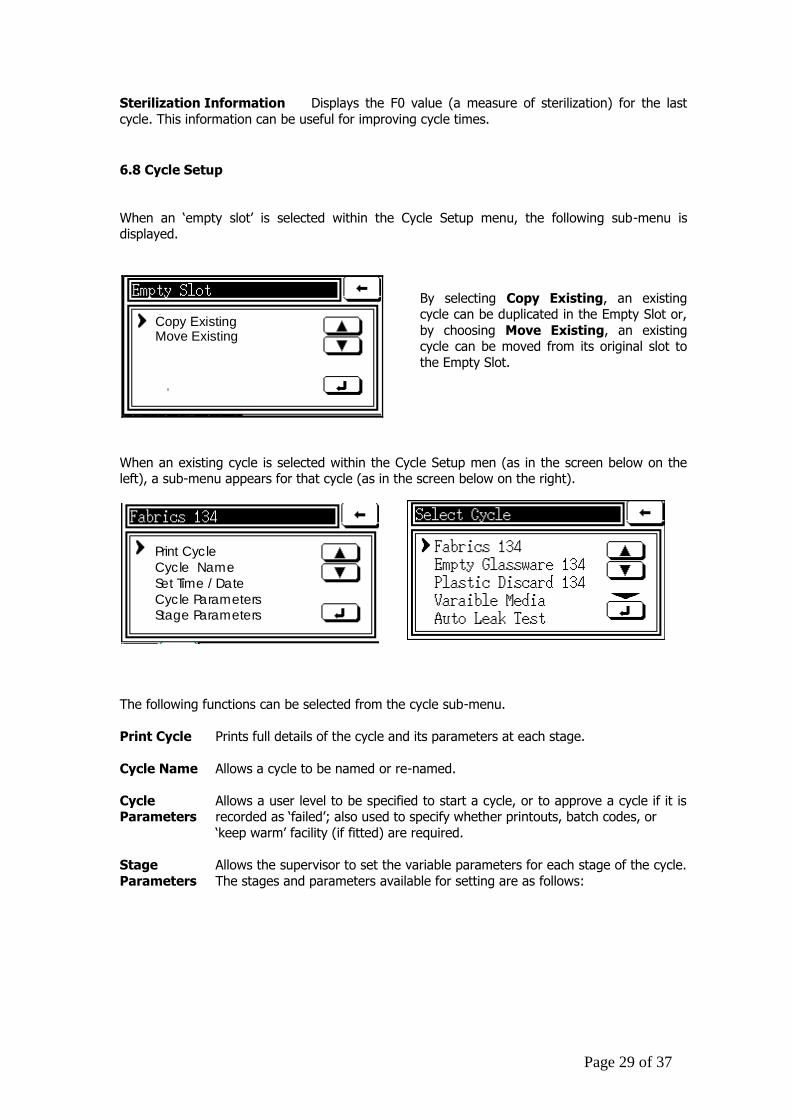
6.5 Set Time/Date
Selection of this function allows the system clock to be set using the screens. The browse buttons are used to move between the date and time screens.
6.6 Alarms
This function calls up the Alarm List screen (illustrated in the preceding section). The Reset
button is only used when no cycle is running.
6.7 Status
By selecting Status, a list of the following information display screens appears.
Machine Information Displays the type and version of the autoclave, and its software version.
View Analogs Displays the analog inputs to the control system – vent, load, keep
warm (if fitted), temperature channels, jacket pressure (if fitted), chamber pressure. The raw
data are displayed by signal direct from the sensor, together with the calibration-adjusted figures.
View Inputs Shows the condition of key inputs required to run a cycle, such as
water level or door status, as monitored by the sensors and switches of the system.
View Outputs Shows the condition of various outputs whilst running a cycle, such as
valves or pumps, in order to assist with identifying faults or problems.
Page 29 of 37
Sterilization Information Displays the F0 value (a measure of sterilization) for the last
cycle. This information can be useful for improving cycle times.
6.8 Cycle Setup
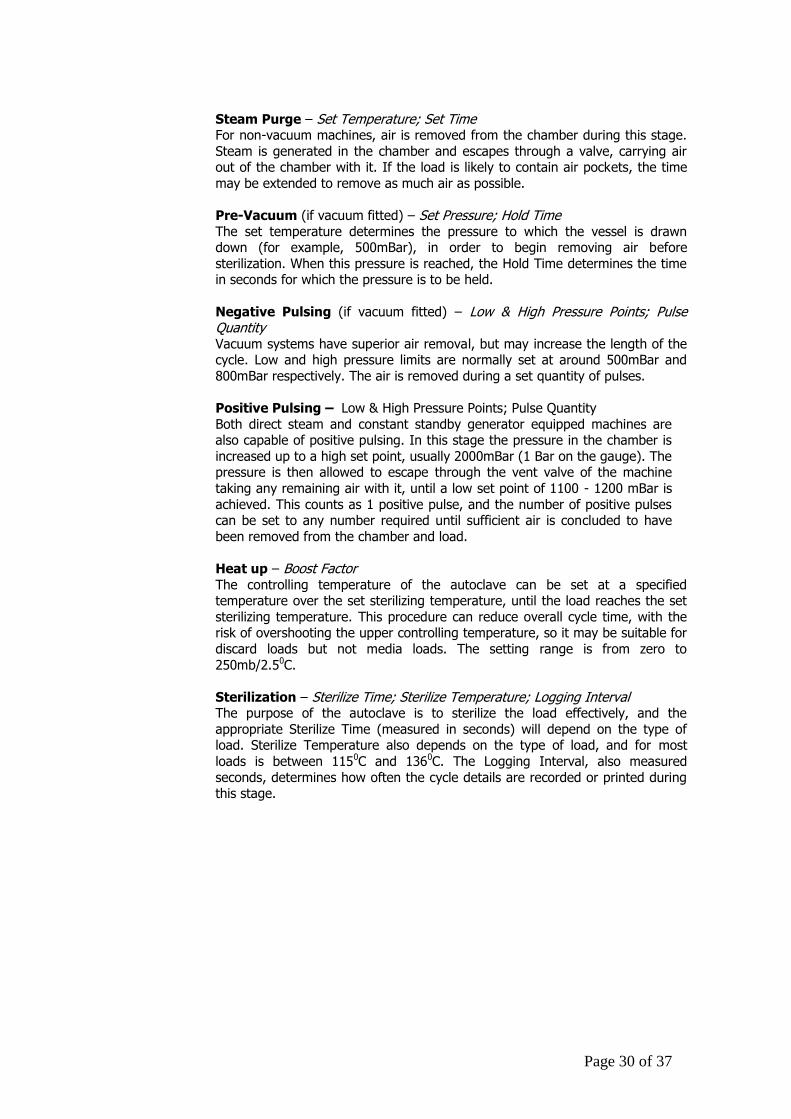
When an ‘empty slot’ is selected within the Cycle Setup menu, the following sub-menu is displayed.
Copy ExistingMove Existing
By selecting Copy Existing, an existing cycle can be duplicated in the Empty Slot or,
by choosing Move Existing, an existing cycle can be moved from its original slot to
the Empty Slot.
When an existing cycle is selected within the Cycle Setup men (as in the screen below on the left), a sub-menu appears for that cycle (as in the screen below on the right).
Print Cycle
Cycle Name
Set Time / Date
Cycle ParametersStage Parameters
The following functions can be selected from the cycle sub-menu.
Print Cycle Prints full details of the cycle and its parameters at each stage.
Cycle Name Allows a cycle to be named or re-named.
Cycle Allows a user level to be specified to start a cycle, or to approve a cycle if it is Parameters recorded as ‘failed’; also used to specify whether printouts, batch codes, or
‘keep warm’ facility (if fitted) are required.
Stage Allows the supervisor to set the variable parameters for each stage of the cycle.
Parameters The stages and parameters available for setting are as follows:
Page 30 of 37
Steam Purge – Set Temperature; Set Time For non-vacuum machines, air is removed from the chamber during this stage.
Steam is generated in the chamber and escapes through a valve, carrying air out of the chamber with it. If the load is likely to contain air pockets, the time
may be extended to remove as much air as possible.
Pre-Vacuum (if vacuum fitted) – Set Pressure; Hold Time
The set temperature determines the pressure to which the vessel is drawn down (for example, 500mBar), in order to begin removing air before
sterilization. When this pressure is reached, the Hold Time determines the time in seconds for which the pressure is to be held.
Negative Pulsing (if vacuum fitted) – Low & High Pressure Points; Pulse Quantity
Vacuum systems have superior air removal, but may increase the length of the cycle. Low and high pressure limits are normally set at around 500mBar and
800mBar respectively. The air is removed during a set quantity of pulses.
Positive Pulsing – Low & High Pressure Points; Pulse Quantity
Both direct steam and constant standby generator equipped machines are also capable of positive pulsing. In this stage the pressure in the chamber is
increased up to a high set point, usually 2000mBar (1 Bar on the gauge). The pressure is then allowed to escape through the vent valve of the machine
taking any remaining air with it, until a low set point of 1100 - 1200 mBar is
achieved. This counts as 1 positive pulse, and the number of positive pulses can be set to any number required until sufficient air is concluded to have
been removed from the chamber and load.
Heat up – Boost Factor The controlling temperature of the autoclave can be set at a specified temperature over the set sterilizing temperature, until the load reaches the set
sterilizing temperature. This procedure can reduce overall cycle time, with the risk of overshooting the upper controlling temperature, so it may be suitable for
discard loads but not media loads. The setting range is from zero to
250mb/2.50C.
Sterilization – Sterilize Time; Sterilize Temperature; Logging Interval The purpose of the autoclave is to sterilize the load effectively, and the
appropriate Sterilize Time (measured in seconds) will depend on the type of load. Sterilize Temperature also depends on the type of load, and for most
loads is between 1150C and 1360C. The Logging Interval, also measured
seconds, determines how often the cycle details are recorded or printed during this stage.
Page 31 of 37
Cooling – Cooling Type; Cooling Temperature; Cooling Interlock; Logging Interval ‘Cooling type’ offers a choice of:
a. normal cooling, which relies on fan cooling while the steam pressure slowly drops to atmospheric pressure; or
b. dynamic cooling, which uses fan cooling until the pressure has dropped to
1150mba, when air is blown through the chamber to reduce cooling time and assist in drying the load; or
c. ballast cooling, which maintains pressure in the chamber while replacing the steam with air, thus avoiding loss of fluids, particularly for media loads.
‘Cooling temperature’ sets the temperature to which the load must reduce
before it is safe to open the door. To ensure the setting operates safely, the
load probe must be within either the load or a simulated load.
‘Cooling Interlock’ is an optional safety measure which is best suited to liquid loads. When the temperature is set, the cooling cycle is prevented from ending
until the temperature of both the load and the chamber have reduces to the set
level. This setting requires a separate probe to monitor the chamber temperature.
‘Logging Interval’ determines how often the cycle details are recorded or
printed during this stage.
Drying – Drying pressure, Drying time
Only where the system has a vacuum system fitted can a low Drying Pressure be set, whereby any liquid in the chamber will flash to steam at a
significantly lower temperature than 100degC.
Without the vacuum option, drying relies solely on the residual heat inside
the vessel to dry the load. Pressure is set low e.g. 500mBar where available, and time is set in seconds at the supervisor’s discretion.
Air Wash – Low pressure point, High pressure point, Pulse quantity
Air is allowed in to the chamber through the Air Break valve and drawn out
by the vacuum pump to create a flow of air over the load. This removes steam from the chamber and improves the effectiveness of the drying cycle.
Lock Cycle Enables the cycle to be locked or unlocked. A locked cycle cannot be used.
Remove Cycle Allows the cycle to be removed from the menu, thereby creating an Empty Slot.
Page 32 of 37
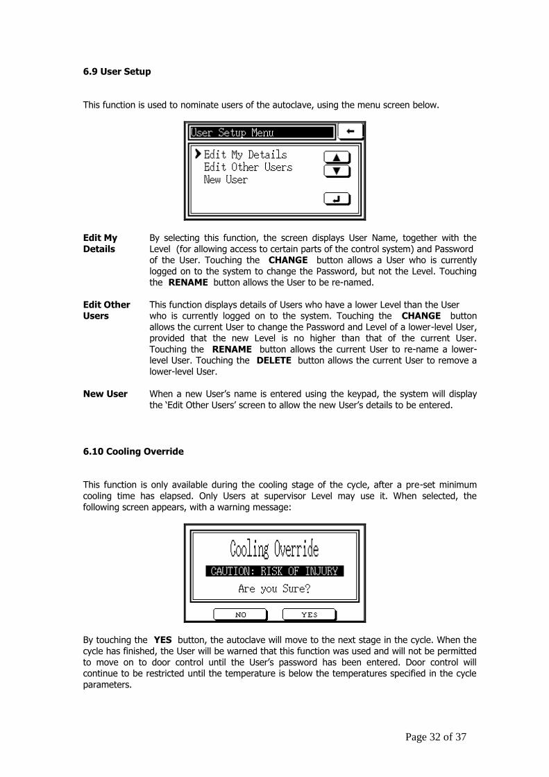
6.9 User Setup
This function is used to nominate users of the autoclave, using the menu screen below.
Edit My By selecting this function, the screen displays User Name, together with the
Details Level (for allowing access to certain parts of the control system) and Password of the User. Touching the CHANGE button allows a User who is currently
logged on to the system to change the Password, but not the Level. Touching the RENAME button allows the User to be re-named.
Edit Other This function displays details of Users who have a lower Level than the User Users who is currently logged on to the system. Touching the CHANGE button
allows the current User to change the Password and Level of a lower-level User, provided that the new Level is no higher than that of the current User.
Touching the RENAME button allows the current User to re-name a lower-level User. Touching the DELETE button allows the current User to remove a
lower-level User.
New User When a new User’s name is entered using the keypad, the system will display
the ‘Edit Other Users’ screen to allow the new User’s details to be entered.
6.10 Cooling Override
This function is only available during the cooling stage of the cycle, after a pre-set minimum
cooling time has elapsed. Only Users at supervisor Level may use it. When selected, the
following screen appears, with a warning message:
By touching the YES button, the autoclave will move to the next stage in the cycle. When the
cycle has finished, the User will be warned that this function was used and will not be permitted
to move on to door control until the User’s password has been entered. Door control will continue to be restricted until the temperature is below the temperatures specified in the cycle
parameters.
Page 33 of 37
7. CARE AND MAINTENANCE Touchclave Lab autoclaves are designed to be easy to maintain. Simple preventive maintenance, as described in this section, will assist in achieving this objective, whilst
prolonging the life and reliability of the autoclave.
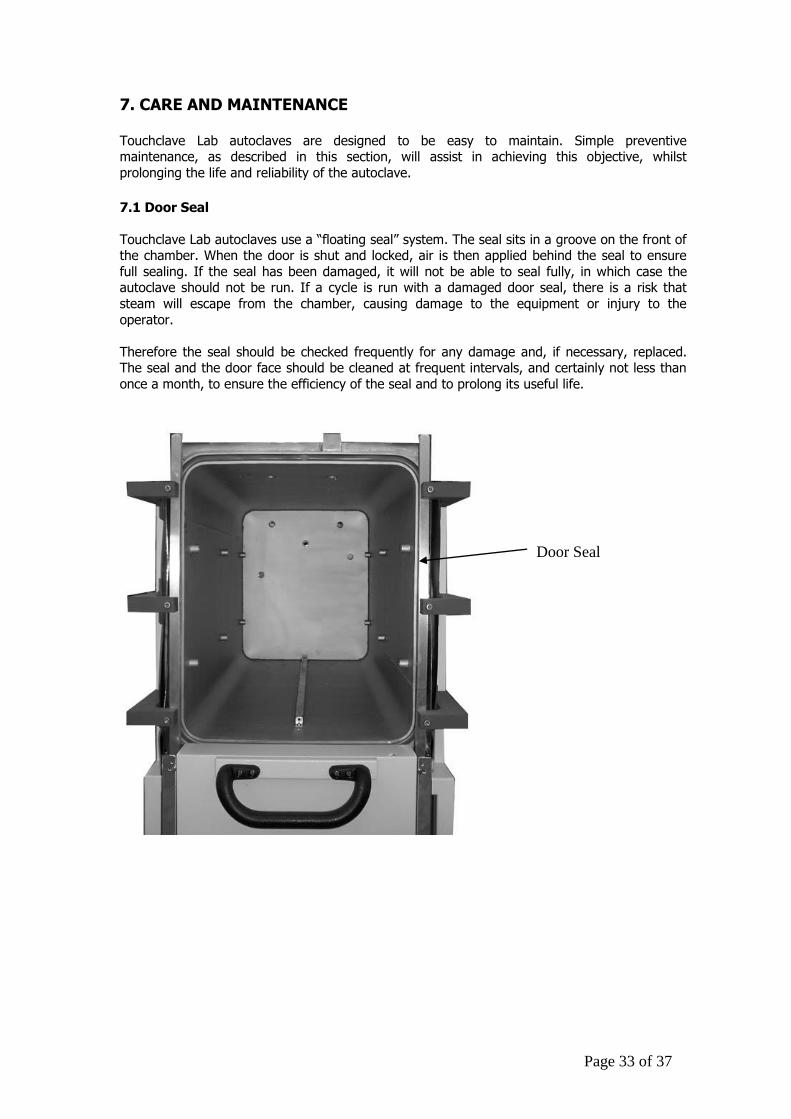
7.1 Door Seal
Touchclave Lab autoclaves use a “floating seal” system. The seal sits in a groove on the front of the chamber. When the door is shut and locked, air is then applied behind the seal to ensure
full sealing. If the seal has been damaged, it will not be able to seal fully, in which case the autoclave should not be run. If a cycle is run with a damaged door seal, there is a risk that
steam will escape from the chamber, causing damage to the equipment or injury to the
operator.
Therefore the seal should be checked frequently for any damage and, if necessary, replaced. The seal and the door face should be cleaned at frequent intervals, and certainly not less than
once a month, to ensure the efficiency of the seal and to prolong its useful life.
Door Seal
Page 34 of 37
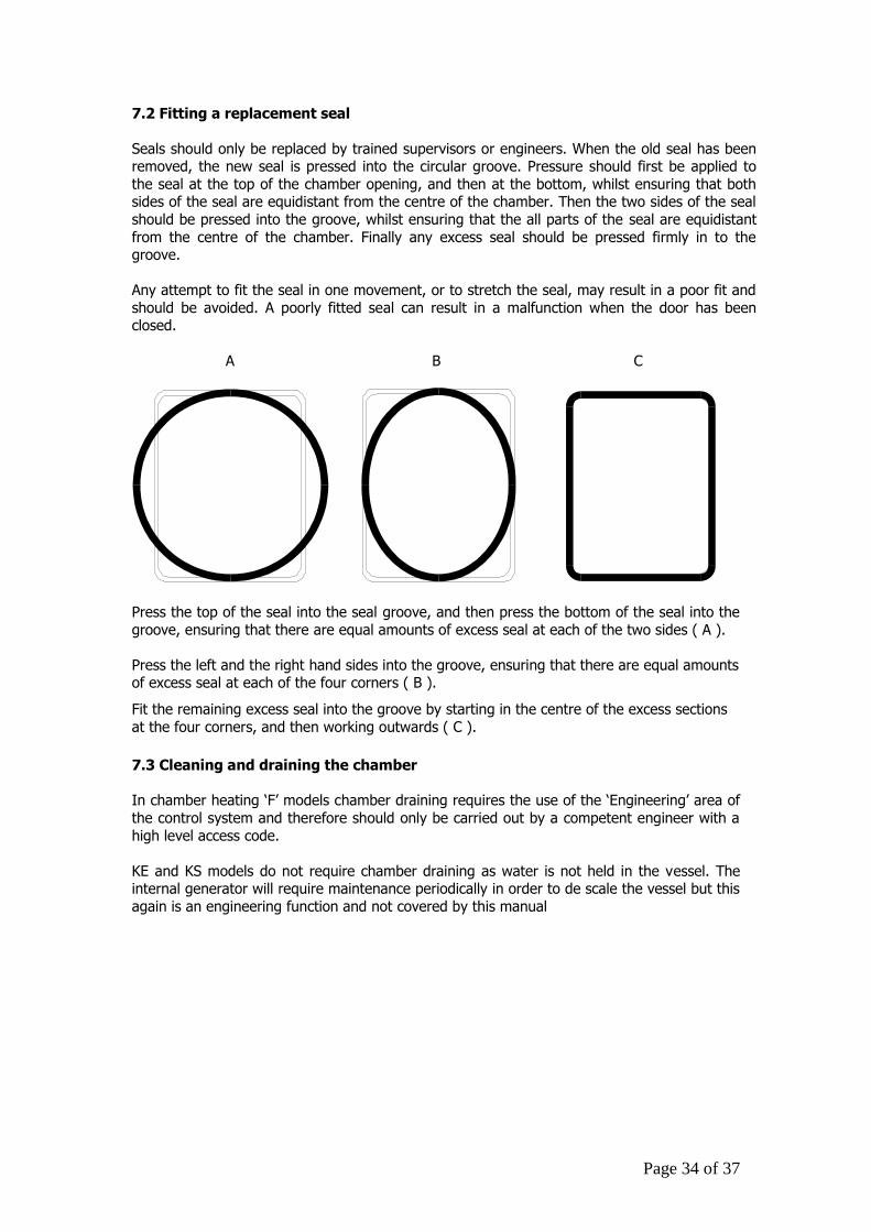
7.2 Fitting a replacement seal
Seals should only be replaced by trained supervisors or engineers. When the old seal has been removed, the new seal is pressed into the circular groove. Pressure should first be applied to
the seal at the top of the chamber opening, and then at the bottom, whilst ensuring that both sides of the seal are equidistant from the centre of the chamber. Then the two sides of the seal
should be pressed into the groove, whilst ensuring that the all parts of the seal are equidistant
from the centre of the chamber. Finally any excess seal should be pressed firmly in to the groove.
Any attempt to fit the seal in one movement, or to stretch the seal, may result in a poor fit and
should be avoided. A poorly fitted seal can result in a malfunction when the door has been closed.
A B C
Press the top of the seal into the seal groove, and then press the bottom of the seal into the
groove, ensuring that there are equal amounts of excess seal at each of the two sides ( A ).
Press the left and the right hand sides into the groove, ensuring that there are equal amounts of excess seal at each of the four corners ( B ).
Fit the remaining excess seal into the groove by starting in the centre of the excess sections
at the four corners, and then working outwards ( C ).
7.3 Cleaning and draining the chamber
In chamber heating ‘F’ models chamber draining requires the use of the ‘Engineering’ area of
the control system and therefore should only be carried out by a competent engineer with a
high level access code.
KE and KS models do not require chamber draining as water is not held in the vessel. The internal generator will require maintenance periodically in order to de scale the vessel but this
again is an engineering function and not covered by this manual
Page 35 of 37
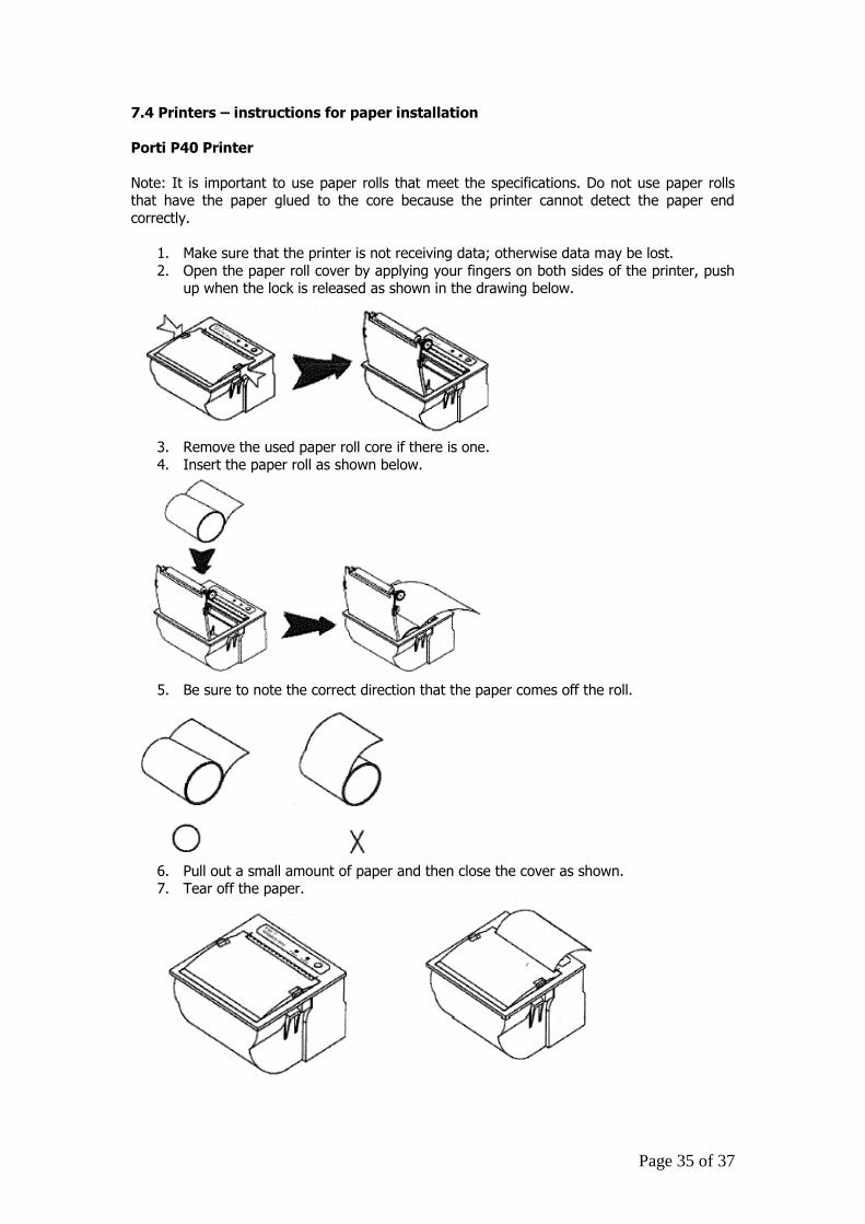
7.4 Printers – instructions for paper installation
Porti P40 Printer
Note: It is important to use paper rolls that meet the specifications. Do not use paper rolls that have the paper glued to the core because the printer cannot detect the paper end
correctly.
1. Make sure that the printer is not receiving data; otherwise data may be lost.
2. Open the paper roll cover by applying your fingers on both sides of the printer, push up when the lock is released as shown in the drawing below.
3. Remove the used paper roll core if there is one.
4. Insert the paper roll as shown below.
5. Be sure to note the correct direction that the paper comes off the roll.
6. Pull out a small amount of paper and then close the cover as shown. 7. Tear off the paper.
Page 36 of 37
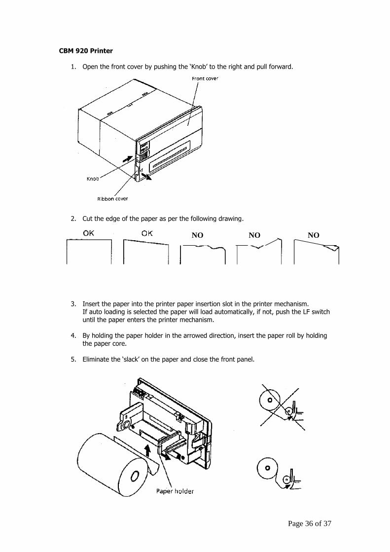
CBM 920 Printer
1. Open the front cover by pushing the ‘Knob’ to the right and pull forward.
2. Cut the edge of the paper as per the following drawing.
3. Insert the paper into the printer paper insertion slot in the printer mechanism.
If auto loading is selected the paper will load automatically, if not, push the LF switch
until the paper enters the printer mechanism.
4. By holding the paper holder in the arrowed direction, insert the paper roll by holding
the paper core.
5. Eliminate the ‘slack’ on the paper and close the front panel.
NO
NO NO
Page 37 of 37
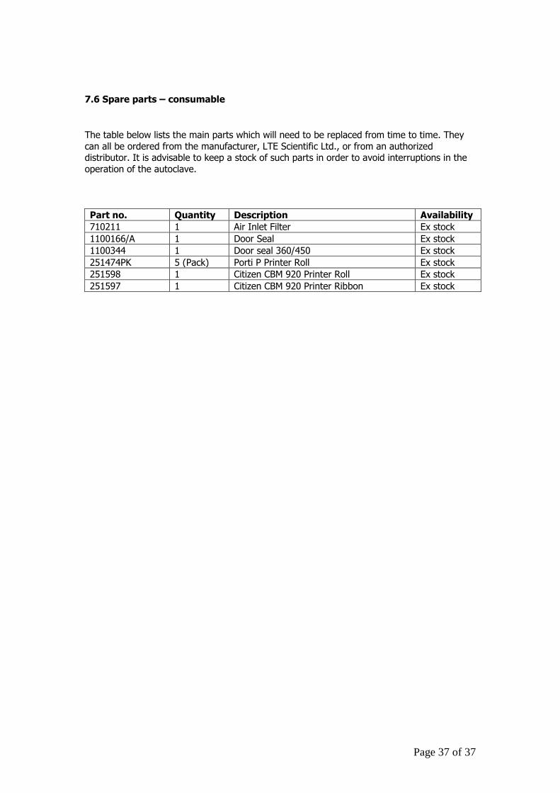
7.6 Spare parts – consumable
The table below lists the main parts which will need to be replaced from time to time. They
can all be ordered from the manufacturer, LTE Scientific Ltd., or from an authorized distributor. It is advisable to keep a stock of such parts in order to avoid interruptions in the
operation of the autoclave.
Part no. Quantity Description Availability
710211 1 Air Inlet Filter Ex stock
1100166/A 1 Door Seal Ex stock
1100344 1 Door seal 360/450 Ex stock
251474PK 5 (Pack) Porti P Printer Roll Ex stock
251598 1 Citizen CBM 920 Printer Roll Ex stock
251597 1 Citizen CBM 920 Printer Ribbon Ex stock