Embed Size (px)
Citation preview
eCoal.plV2.1
Adaptive Controllerlicensed by the Institute for Chemical Processing of Coal
User Manual
Kutno, 28/03/2013
1/59
List of contents 1.Foreword......................................................................................................9
1.1.Intended use..........................................................................................9 1.2.Algorithm - Group Combustion..................................................................9 1.3.Group combustion histogram..................................................................11 1.4.Specification.........................................................................................12
2.Safety........................................................................................................13 3.Installation.................................................................................................14
3.1.Environmental conditions........................................................................14 3.2.Installation of a control panel..................................................................14 3.3.Connecting measuring sensors................................................................15 3.4.Connecting room thermostat...................................................................16 3.5.Connecting sensors to external alarm input...............................................16 3.6.Connecting control devices.....................................................................17 3.7.PC connection.......................................................................................17 3.8.Ethernet connection...............................................................................18
4.Controller operation.....................................................................................19 4.1.Control panel - keyboard........................................................................19 4.2.Control panel - Maintenance level............................................................20 4.3.Controller operation modes.....................................................................22
a)Manual mode.......................................................................................22 b)Automatic mode...................................................................................22
4.4.Central heating temperature setting.........................................................23 4.5.Domestic hot water temperature setting...................................................23 4.6.Function - fuel charge............................................................................24
5.Controller programming................................................................................24 5.1.Combustion parameters.........................................................................24
a) Parametry spalania (Combustion parameters) – typ Tłokowy (Ram type) - ręczny (Manual).......................................................................................25 b) Parametry spalania (Combustion parameters) – typ Tłokowy (Ram type) - grupowy (Group)......................................................................................26 c) Parametry spalania (Combustion parameters) – typ Tłokowy (Ram type)- eCoal (eCoal)...........................................................................................27 d) Parametry spalania (Combustion parameters) – typ Zasypowy (Hopper type).............................................................................................................28
5.2. Parametry użytkownika (User parameters)...............................................29 5.3.Programmers........................................................................................30
a)Programator CO (CH programmer)..........................................................32 b)Programator CWU (DHW programmer)....................................................32 c)Programator pogodowy (Weather compensation programmer)....................32 d)Programator pokojowy (Room programmer).............................................33 e)Programator pompy cyrkulacyjnej (Circulation pump programmer)..............34 f)Programator Auto-Lato (Automatic summer programmer)..........................34 g)Programator ogrzewania podłogowego (Floor heating programmer).............34
5.4.Internet...............................................................................................35 5.5.Data i czas (Date and time)....................................................................36 5.6.Parametry zaawansowane (Advanced parameters).....................................36
6.Alarms.......................................................................................................39 7.Proxy software - eCoal.pl..............................................................................40
7.1.Controller software update......................................................................41
2/59

7.2.Controller connection to local network......................................................45 7.3.Setting local network parameters in the controller......................................46 7.4.Website panel in the controller................................................................48 7.5.Connecting controller to remote access service..........................................52 7.6. Sharing controller with other user...........................................................57
3/59
Visit our websites
http://eCoal.pl
http://eSterownik.pl
The websites include:
•Answers to the frequently asked questions – FAQ
•Latest version of eCoal.pl controller software
•Latest version of eCoal.pl controller website
•eSterownik.pl website developed for eCoal.pl users provides
Remote Access to the controller via Internet, if no public IP is
available. A proxy server allows communication, if no public IP
address is available.
•User Forum
•Software test builds are available on the Forum
4/59
eCoal.pl software - Version history
Version 0.3.1.6:
• Added: new 30 kW power for Spalanie Grupowe (Group combustion)
• Changed: error causing feeder operation time reset following controller reset
Version 0.3.1.4:
• Added: new combustion algorithm - Spalanie Grupowe (Group Combustion)
• Added: manual combustion process control - two-state operation
• Added: manual hopper type boiler operation (emergency grate combustion)
• Added: automatic feeder and blower OFF in manual mode
• Added: blower and feeder ON in manual mode with the following alarm: Uszkodzony czujnik temperatury spalin (Flue gas temperature sensor failure)
• Added: floor heating pump switches to cyclic operation at set temperature
• Added: floor heating pump OFF at CH temperature 4 °C below Temp.MIN.CO (min. CH temperature)
• Added: floor heating pump OFF in LATO (Summer) mode
• Added: new alarm - Wysoka temp. podajnika (High feeder temperature) - activated 5 °C below Max temp.podajnika (Max. feeder temperature)
• Added: emergency CH pump OFF at temp. MAX (max. temperature) set in Ust.zaawansowane (Advanced settings)
• Changed: simplified DHW priority - CH/floor heating pump always OFF in DHW priority mode
• Changed: removed prolonged operation time after pre-set temperature reduction
• Changed: reduced idle time in sustain mode to 5 minutes (for pellet only)
• Changed: mixing pump may activate, if CH temperature is higher than return temperature by 1 °C
• Changed: CH pump will activate 2 °C below minimum temperature
• Changed: DHW pump will activate 2 °C below minimum temperature
• Changed: floor heating pump will activate 2 °C below minimum temperature
• Amended: sustain cycle activated after 5 minutes following controller reset
• Added: website prompts
• Added: graph display of a single readout when clicking temperature value on the diagram
• Added: graph settings stored in browser cookies
• Added: feeder idle time statistics for group combustion - Histogram on the website
• Added: parameter preview on the graph
• Added: local web server file buffering
• Added: automatic fuel consumption calculation based on feeder operation time
• Added: logging fuel quantity after feeder operation time reset (LCD panel and website)
5/59
• Added: winter/summer operation mode logging after new fuel charge The data will be automatically transmitted to eSterownik.pl
• Added: automatic entry on new fuel charge on eSterownik.pl after feeder operation time reset via LCD and website
• Changed: improved SD card data readout speed
• Added: new parameter - Korekta mocy dmuchawy w grzaniu (+-6%) (Blower power correction in heating mode)
• Added: new parameter - Okres rejestracji (Logging period), defines data logging period: 60 sec, 30 sec, 20 sec, 10 sec.
• Added: new parameter - Priorytet CWU (DHW priority) - individual DHW priority function - mode removed from Tryb pracy CWU (DHW operation mode)
• Added: new parameter - Temp. zał. pompy mieszającej (Mixing pump activation temperature)
• Added: new parameter - Temp. zał. pompy cyrkulacyjnej (Circulation pump activation temperature)
• Added: new parameters - Czas pracy/postoju dla pompy podłogowej (Floor heating pump operation/idle time)
• Added: new parameter - Algorytm wygaszenia kotła (Boiler put out algorithm) (Nieaktywny, tylko grzanie, tylko podt., aktywny) (Inactive, heating only, sustain only, active)
• Added: new parameter - Podbicie temp.CO przy aktywnym priorytecie CWU (CH temperature increase in DHW priority mode)
• Added: new parameter - Czas wyrzutu paliwa z podajnika (Fuel removal time from the feeder), active Zapłon paliwa (Fuel ignition) alarm
• Changed: 5 °C temperature setting step removed for reg.pogodowego (Weather compensation programmer)
• Changed: ilość powtórzeń w podtrzymaniu (repeats in sustain mode) increased to 5
• Changed: pracy/postoju pompy CO (CH pump operation/idle time) increased from 60 min to 99 min with reg.pokojowy (room thermostat) active
• Changed: Max.temp podajnika (Max. feeder temperature) parameter range (40...110 °C)
• Added: temperature sensor readout averaging
• Added: status field on LCD for floor heating temperature sensor - T.PODLG
• Added: 'P’ marking on the display indicating priorytet CWU (DHW priority) mode active
• Added: 'T' - Termostat (Thermostat) active, and 'K' - Reg.pokojowy (Room thermostat) active
• Changed: PIN prompt for Parametry zaawansowane (Advanced parameters) menu
• Added: new parameter - Praca automatyczna pompy cyrkulacyjnej w trybie ręcznym(Circulation pump automatic operation in manual mode)
Version 0.2.8.1:
• Changed: error causing 5 sec feeder operation in heating mode after each controller reset
Version 0.2.8.0:
6/59
• Added: information display on the web site, that the controller is in LATO (Summer) mode(important information in Auto-Lato (Automatic summer) mode
• Added: Typ kotła (Boiler type) parameter. Change in parameter does not restore factory settings.
• Added: set temperature logging for reg.pokojowy (Room thermostat) - graphs
• Added: set temperature logging for reg.podłogówki (Floor heating thermostat) - graphs
• Added: additional parameters for Alarm zewnętrzny (External alarm): Opóźnienie (Delay), Inwersja wejścia (Output inversion), Zatrzymanie sterownika (Controller OFF)
• Added: parameter - Funkcja pompy mieszającej (Mixing pump function): Mieszająca (Mixing), Cyrkulacyjna (Circulation), Podłogowa (Floor heating)
• Added: Programator Pompy Podłogowej (Floor heating pump controller)
• Added: parameter - Funkcja wyjścia pompy CWU (DHW pump output function): CWU, CWU + pompa mieszająca (DHW, DHW + mixing pump). This function enables use of DHW pump as a mixing pump.
• Added: DHW pump operation mode on the website depending on if DHW pump is activated based on DHW algorithm (green) or mixing pump algorithm (yellow)
• Added: new DHW operation modes: AutoLato-temp (Automatic summer - temperature), AutoLato-programator (Automatic summer - programmer)
• Added: Auto-Lato (Automatic summer) mode programmer
• Added: factory settings restored by pressing ESC during power on.
• Added new parameter - Histereza dla reg.pokojowego (Hysteresis for room thermostat)(Range: 0.1 - 2.0 °C)
• Added new parameter - Histereza trybu Auto-Lato (Automatic summer mode hysteresis)(Range: 0.5 - 5.0 °C)
• Added new parameter - Czas pracy podajnika w grzaniu (Feeder operation time in heating mode) (Range: 3 - 20 sec)
• Added: sustain cycle is activated after each controller fadeout/reset
• Added: parameter - Niezależna praca pompy mieszającej (Independent mixing pump operation). If parameter is active, mixing pump operates independently from the CH pump (all modes)
• Added: boiler put out in sustain mode - Wygaszenie kotła (Boiler put out) alarm is generated when the flue gas temperature will not rise by 5 °C in the sustain mode
• Added: new boiler type - PELLET (Pellet)
• Limited: number of feeding cycles in sustain mode to 5 steps
• Removed: limited to 45 days at planning next fuel charge
• Changed: Histereza CWU (DHW hysteresis) parameter resolution to 0.1 °C
• Changed: CH pump activation in summer mode above 80 °C, pump deactivation 5 °C below
• Changed: DHW pump activation in summer mode above 70 °C, pump deactivation 5 °C below
• Mixing pump operates depending on CH pump operation. Pump deactivation temperature 3°C below minimum temperature (not less than 39 °C), activation temperature 0.5 °C above minimum temperature
7/59
• Czas postoju pompy cyrkulacyjnej (Circulation pump idle time) reduced to 0 min - circulation pump may operate in continuous mode.
• Parameter update for Ogniwo EKO+ 16kW boiler
• Analiza wygaszenia kotła w grzaniu (Boiler put out analysis in heating mode) - Wygaszenie kotła (Boiler put out) alarm is generated in heating mode, if flue gas temperature falls below 50 °C and is maintained for at least 30 minutes
• Reduced: blower power in sustain mode to 30%
• Solved: problem with delayed switching to heating (room thermostat)
• Improved: SD card compatibility
Version 0.0.2.4:
• Added: Feeder operation time counter. Feeder operation time is displayed on the operator panel in position 4 (press ↓ arrow down 3x) - “CP.POD:” field. After feeding fuel to the hopper, hold → (right arrow) or ← (left arrow) to reset the time. Time may also be reset viaour website: Ustawienia użytkownika (User settings), Wyzeruj (Reset) button
• Added: Indication of low fuel level in the hopper based on determined feeder operation time. Feeder operation time may be set via our website: Parametry użytkownika (User parameters), Czas do opróżnienia zasobnika [min] (Time to empty hopper [min]) field.
• Added: Logging new fuel batch data in alarms and events.
• Added: Anticipated date of the next coal charge. Algorithm calculates date based on defined hopper emptying time. The date is displayed after the next charge following feeder operation time reset.
• Added: Factory parameters for OGNIWO EKO PLUS 16kW boiler
• Improved: communication with Zdalny Dostęp (Remote access) service
Version 0.0.2.0:
• Added: Zdalny Dostęp (Remote access) service – http://eSterownik.pl
• Added: Languages: Polish, English, German, Czech
• Added: New advanced parameters: Tryb pracy pompy CO (CH pump operation mode), Czas pracy pompy CO (CH pump operation time), Czas postoju pompy CO dla regulatora pokojowego i termostatu (CH pump idle time for room thermostat and thermostat)
• Added: Alarm zewnętrzny (External alarm) via binary controller input: KONT
• Added: Two new advanced settings parameters: Auto (Automatic) mode
• Lato (Summer) (ON/OFF) and Temp.zew (External temperature) for Auto mode
• Lato (Summer) – automatic switching to LATO (Summer) mode after exceeding set external temperature.
• Added: New user parameter: Regulator temp.wewnętrznej (External temperature thermostat) to select temperature adjustment in the room: Wyłączony (OFF), Prog.Pokojwy (Room thermostat), Termostat (Thermostat). Separation of room and boiler thermostat enable operation of two thermostats.
• Changed: Zadawanie temperatury (Temperature setting) parameter for Regulator temperatury kotła (Boiler thermostat). Options: Prog.CO (CH thermostat), Prog.Pogodowy (Weather compensation programmer). Separation of room and boiler thermostat enable operation of two thermostats.
8/59
• Changed: User parameters – Przywracanie ustawień fabrycznych (Restore factory settings). Restore settings for a specific boiler power (15 kW, 25 kW, 35 kW).
• Changed: CH pump operation time in DHW priority mode: 5/30 min
1.ForewordeCoal.pl is an adaptive controller developed with the research department of
the Institute for Chemical Processing of Coal and Elektro-System S. C. -
industrial automatics and IT company.
The essence and innovativeness of controller operation consists in ensuring
continuous boiler combustion process by simultaneous operation of two
regulators - one controlling fuel quantity depending on power and second
controlling air quantity for optimum combustion process.
The controller features flue gas temperature measurement, also used as a flue
gas analyser to determine optimum air supply for fuel combustion. The
combustion parameters are automatically selected without additional service or
maintenance required.
1.1.Intended useeCoal.pl controller is intended for automatic supervision of central heating
boiler with an automatic screw feeder and a blower. It may also be used to
control domestic hot water (DHW) pump, and in a systems fitted with a mixing
pump it maintains minimum return water temperature. The controller can also
supervise fuel feeder operation: fuel ignition (back burning). eCoal.pl is
compatible with the eSterownik.pl platform. The web interface allows for
intuitive change of operation parameters. It also allows controller software
update. The latest software version is available on http://eCoal.pl and
eSterownik.pl forum.
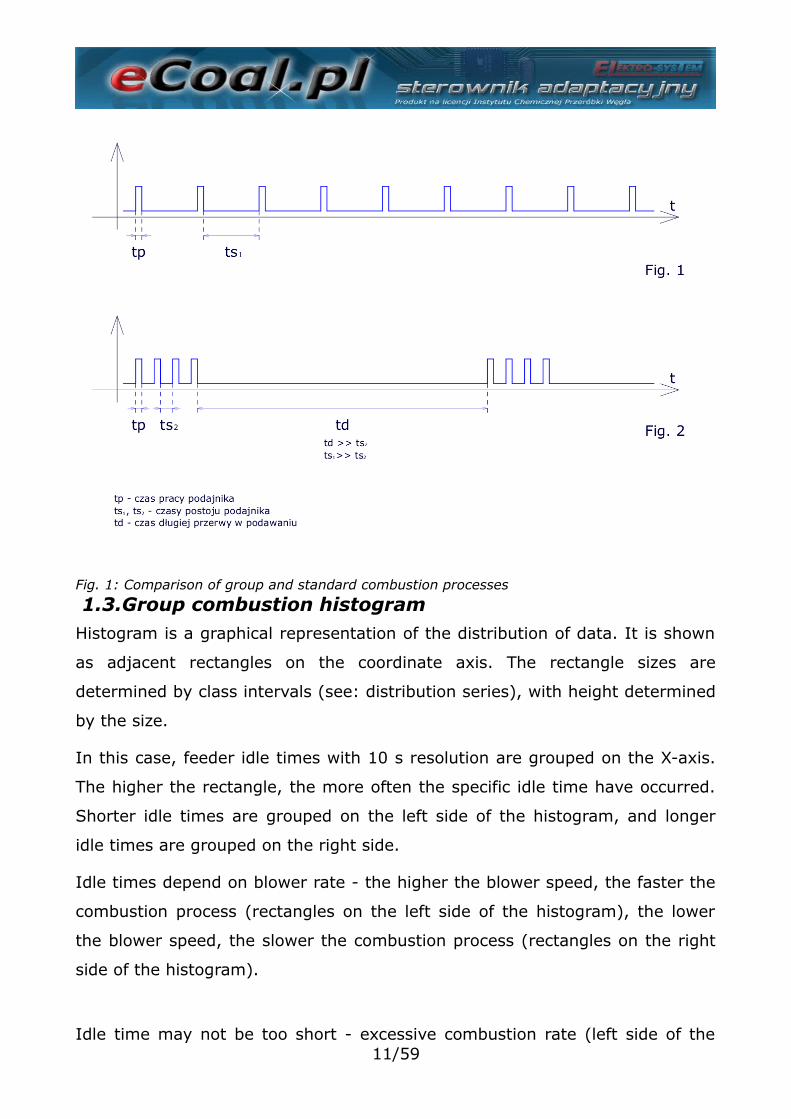
1.2.Algorithm - Group CombustionBurning solid fuels in a boiler with an automatic burner is a complex process,
both in respect of low fuel uniformity, e.g. particle size, and variable physical
and chemical parameters, essential for combustion processes.
9/59
Coal is an especially problematic fuel, whose properties depend not only on its
origin - a coal mine, but also on the specific coal bed. Coal fuel combustion in
automatic boilers is a stochastic process.
In commonly used solutions, fuel feeding and combustion are considered as
continuous processes. It means that the feeder operates in regular and
repeatable operation/idle cycles, and its power changes depending on
operation and idle time ratio, which does not affect repeatability.
The disadvantages of continuous fuel feeding and combustion processes,
include issues with fuel to air ratio due to a stochastic nature of the
combustion process, and the fact that feeding fuel batches in small intervals
does not allow complete assessment of the combustion process. Significant
increase in fuel feeding interval must be related with significant increase in
batch feeding time to reach required power, causing temporary incomplete
combustion in form of a smoke.
Based on the combustion process testing in automatic solid fuel boilers, fuel
batching, and therefore impulse (discrete) combustion process allows to asses,
if the combustion process of a previous batch been completed.
Treating the fuel batching process, and therefore the combustion process, not
as a continuous but as an impulse process is revolutionary innovation.
Realization of a new control method consists in group repeating of fuel feeding
and short feeder idle time cycles, following a long interval to complete
combustion of the previous fuel batch, and the moment of complete
combustion is determined based on flue gas temperature trend analysis.
10/59
1.3.Group combustion histogramHistogram is a graphical representation of the distribution of data. It is shown
as adjacent rectangles on the coordinate axis. The rectangle sizes are
determined by class intervals (see: distribution series), with height determined
by the size.
In this case, feeder idle times with 10 s resolution are grouped on the X-axis.
The higher the rectangle, the more often the specific idle time have occurred.
Shorter idle times are grouped on the left side of the histogram, and longer
idle times are grouped on the right side.
Idle times depend on blower rate - the higher the blower speed, the faster the
combustion process (rectangles on the left side of the histogram), the lower
the blower speed, the slower the combustion process (rectangles on the right
side of the histogram).
Idle time may not be too short - excessive combustion rate (left side of the11/59
Fig. 1: Comparison of group and standard combustion processes
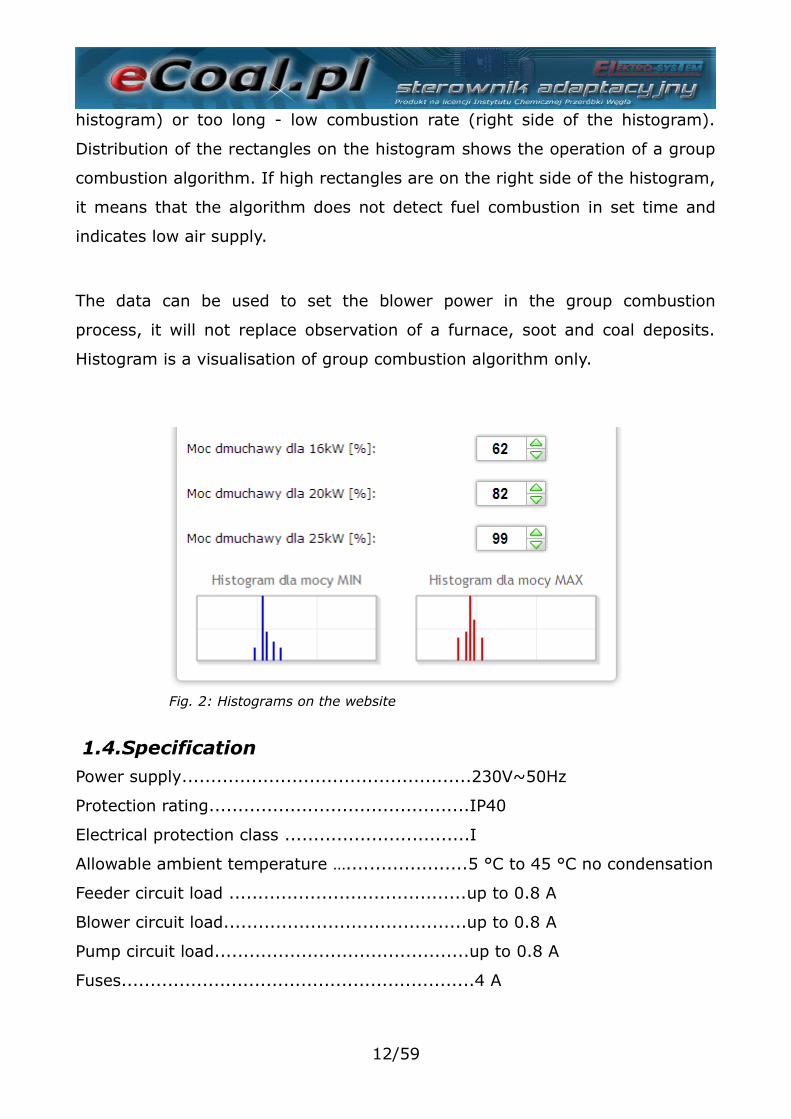
histogram) or too long - low combustion rate (right side of the histogram).
Distribution of the rectangles on the histogram shows the operation of a group
combustion algorithm. If high rectangles are on the right side of the histogram,
it means that the algorithm does not detect fuel combustion in set time and
indicates low air supply.
The data can be used to set the blower power in the group combustion
process, it will not replace observation of a furnace, soot and coal deposits.
Histogram is a visualisation of group combustion algorithm only.
1.4.SpecificationPower supply..................................................230V~50Hz
Protection rating.............................................IP40
Electrical protection class ................................I
Allowable ambient temperature ….....................5 °C to 45 °C no condensation
Feeder circuit load .........................................up to 0.8 A
Blower circuit load..........................................up to 0.8 A
Pump circuit load............................................up to 0.8 A
Fuses.............................................................4 A
12/59
Fig. 2: Histograms on the website
2.Safety• Read the warranty terms and conditions and User manual before
installation. Incorrect installation, operation and maintenance will render the
warranty void.
• Assembly and installation works shall be carried out by the service centre or
personnel with proper qualifications and authorization, in accordance with
current regulations and standards.
• Due to the operation safety, and mains electromagnetic interferences which
may affect operation of the controller and other devices, connect the
controller to the socket with an earthing pin.
• Do not expose controller to water and excessive humidity resulting in
condensation (e.g. rapid ambient temperature changes).
• Do not expose controller to temperature above 45 ºC and below 5 ºC.
• In case the auxiliary grate is used to fire wood or wastes, remove flue gas
sensor from the flue, if the emergency grate combustion mode is not active
(Parametry zaawansowane (Advanced parameters) – Typ podajnika:
Zasypowy (Feeder type: hopper)).
• Wiring must be fixed on the entire length and must not contact water jacket
or flue gas conduits.
• Disconnect mains plug before connecting/disconnecting devices supplied by
the controller.
• During the storm, the controller must be disconnected from 230 V mains.
• The system must be protected with fuses with a correct rating in accordance
with current standards and regulations.
• Do not install the controller with damaged housing or wires.
• All repairs must be carried out by an authorized service centre. In other
case, the warranty is void.
• Flue gas sensor requires cleaning at least once a month.
• The flue gas must be fitted in the middle of the flue diameter.
• In case the sensor cable length exceeds 5 m, shielded cable pairs are
13/59
recommended. Cable shield must be connected to PE terminal on the
controller side only.
3.InstallationAssembly and installation works shall be carried out by the service centre or
personnel with proper qualifications and authorization, in accordance with
current regulations and standards.
3.1.Environmental conditionsDo not expose controller to water and excessive humidity resulting in
condensation (e.g. rapid ambient temperature changes).
Do not expose controller to temperatures above 45 ºC and below 5 ºC.
3.2.Installation of a control panelAn LCD housing is snap fastened. Lead a cable through a gland in a bottom
part of the LCD housing. Connect on end of the cable to a screw terminal on
the display board and lead the other end through the gland in the controller
housing, and connect to a suitable terminal. Connect in accordance with the
following colour codes:
• GND – white
• B – yellow
• A – green
• +12V – brown
Recommended cable: LIYY 4x0.25 mm2.
14/59

3.3.Connecting measuring sensorsActivation of connected devices and controller functions is automatic and
depends on connection of temperature sensors to the controller. E.g.
connecting DHW temperature sensor activates DHW pump operation, and
connecting external temperature sensor allows automatic use of a weather
compensation programmer etc. The sensors must be connected to the
controller in accordance with the markings on the printed circuit board, by
leading the sensor cable via a correct cable gland (description on the housing).
KTY-81-210 type and PT-100 type temperature sensors are used.
If the sensor is not connected, it is signalled with dashes by the sensor
marking.
The controller may detect damaged sensors. Disconnect mains plug before
connecting/disconnecting sensors to the controller and disconnect mains plug
each time.
In case the sensor cable length exceeds 5 m, shielded cable pairs are
recommended. Cable shield must be connected to PE terminal on the controller
side only.
15/59
Fig. 3: Terminal strip for sensors
3.4.Connecting room thermostatRoom thermostat (external device, e.g. Auraton) must be connected to the
controller board to TERM terminals. The thermostat connected to the
controller shall be fitted with potential free contact. In case the room
thermostat is connected, CH temperature is set by switching the contacts on
the boiler: daily comfort (contact closed) or reduced (contact open). The option
may be selected in Ustawieniach użytkownika (User settings) - Regulator
temperatury wewnętrzny: Termostat (Internal temperature controller:
Thermostat).
Higher boiler temperature is set with thermostat contacts closed. With contacts
open, set temperature is lowered, also CH pump may operate in cyclic or
continuous mode or can be switched OFF - set in Parametry zaawansowane
(Advanced parameters) – Tryb pracy pompy CO.
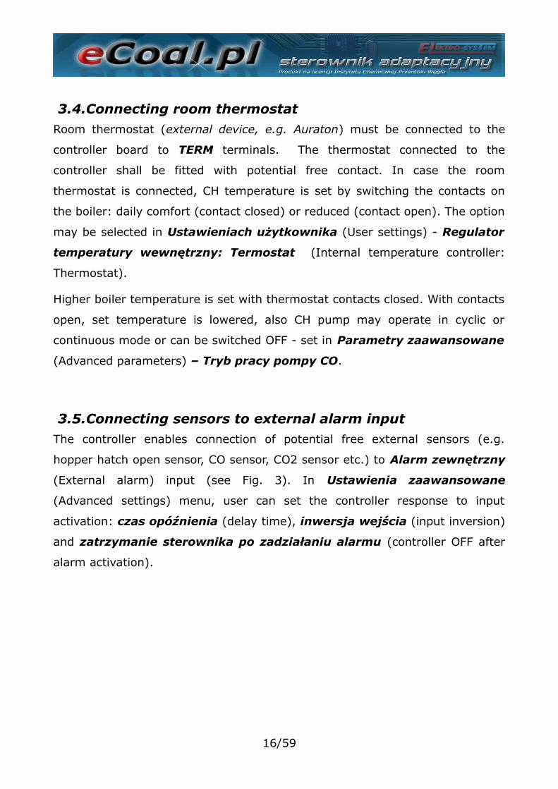
3.5.Connecting sensors to external alarm inputThe controller enables connection of potential free external sensors (e.g.
hopper hatch open sensor, CO sensor, CO2 sensor etc.) to Alarm zewnętrzny
(External alarm) input (see Fig. 3). In Ustawienia zaawansowane
(Advanced settings) menu, user can set the controller response to input
activation: czas opóźnienia (delay time), inwersja wejścia (input inversion)
and zatrzymanie sterownika po zadziałaniu alarmu (controller OFF after
alarm activation).
16/59
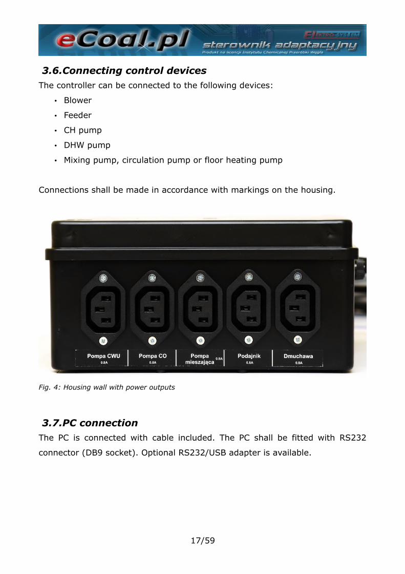
3.6.Connecting control devicesThe controller can be connected to the following devices:
• Blower
• Feeder
• CH pump
• DHW pump
• Mixing pump, circulation pump or floor heating pump
Connections shall be made in accordance with markings on the housing.
3.7.PC connectionThe PC is connected with cable included. The PC shall be fitted with RS232
connector (DB9 socket). Optional RS232/USB adapter is available.
17/59
Fig. 4: Housing wall with power outputs
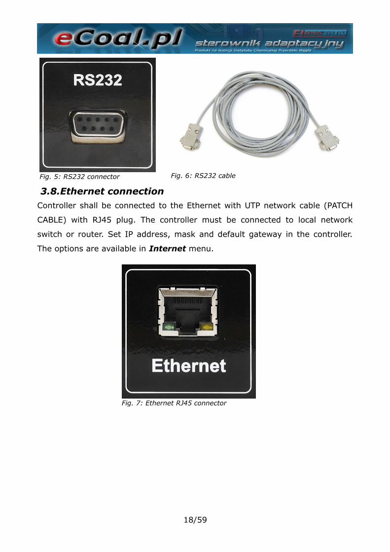
3.8.Ethernet connectionController shall be connected to the Ethernet with UTP network cable (PATCH
CABLE) with RJ45 plug. The controller must be connected to local network
switch or router. Set IP address, mask and default gateway in the controller.
The options are available in Internet menu.
18/59
Fig. 5: RS232 connector
Fig. 7: Ethernet RJ45 connector
Fig. 6: RS232 cable
4.Controller operation
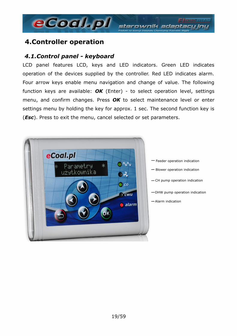
4.1.Control panel - keyboardLCD panel features LCD, keys and LED indicators. Green LED indicates
operation of the devices supplied by the controller. Red LED indicates alarm.
Four arrow keys enable menu navigation and change of value. The following
function keys are available: OK (Enter) - to select operation level, settings
menu, and confirm changes. Press OK to select maintenance level or enter
settings menu by holding the key for approx. 1 sec. The second function key is
(Esc). Press to exit the menu, cancel selected or set parameters.
19/59
Blower operation indication
CH pump operation indication
DHW pump operation indication
Alarm indication
Feeder operation indication
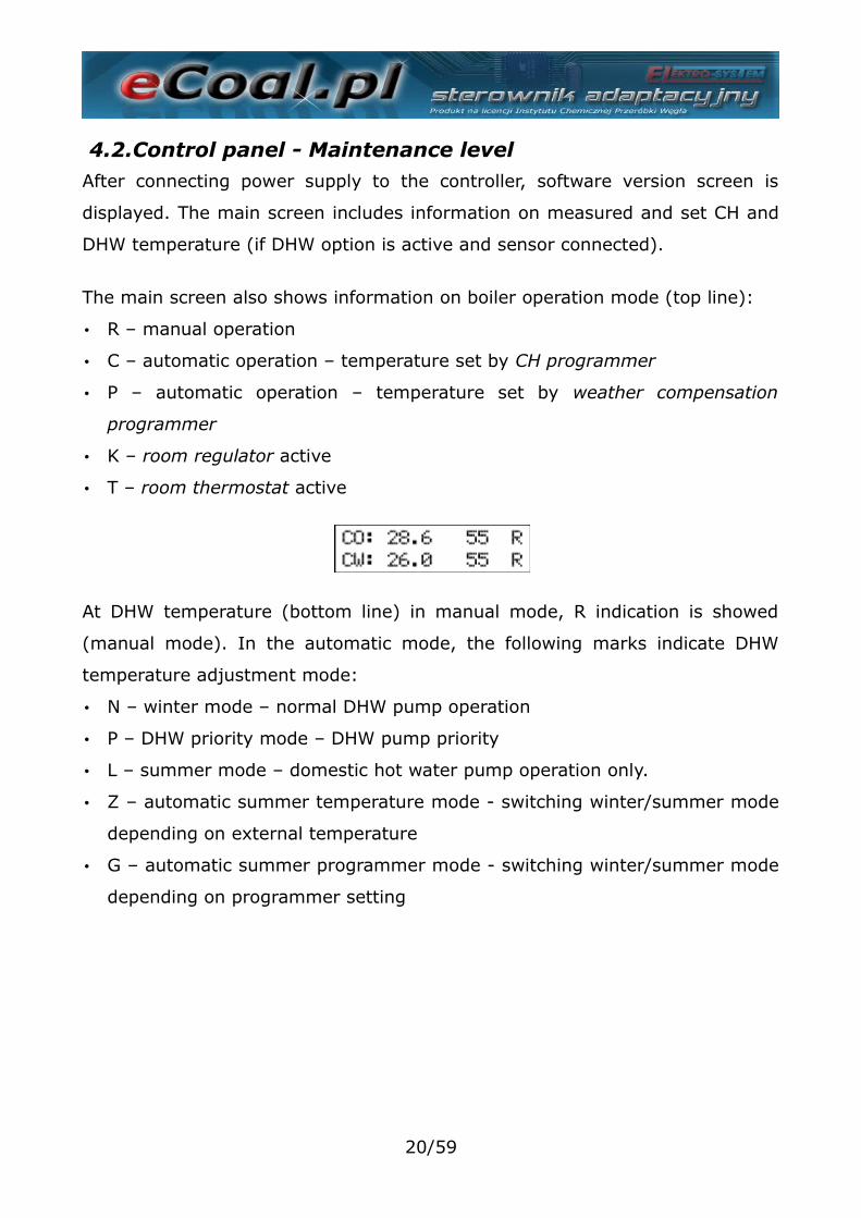
4.2.Control panel - Maintenance levelAfter connecting power supply to the controller, software version screen is
displayed. The main screen includes information on measured and set CH and
DHW temperature (if DHW option is active and sensor connected).
The main screen also shows information on boiler operation mode (top line):
• R – manual operation
• C – automatic operation – temperature set by CH programmer
• P – automatic operation – temperature set by weather compensation
programmer
• K – room regulator active
• T – room thermostat active
At DHW temperature (bottom line) in manual mode, R indication is showed
(manual mode). In the automatic mode, the following marks indicate DHW
temperature adjustment mode:
• N – winter mode – normal DHW pump operation
• P – DHW priority mode – DHW pump priority
• L – summer mode – domestic hot water pump operation only.
• Z – automatic summer temperature mode - switching winter/summer mode
depending on external temperature
• G – automatic summer programmer mode - switching winter/summer mode
depending on programmer setting
20/59
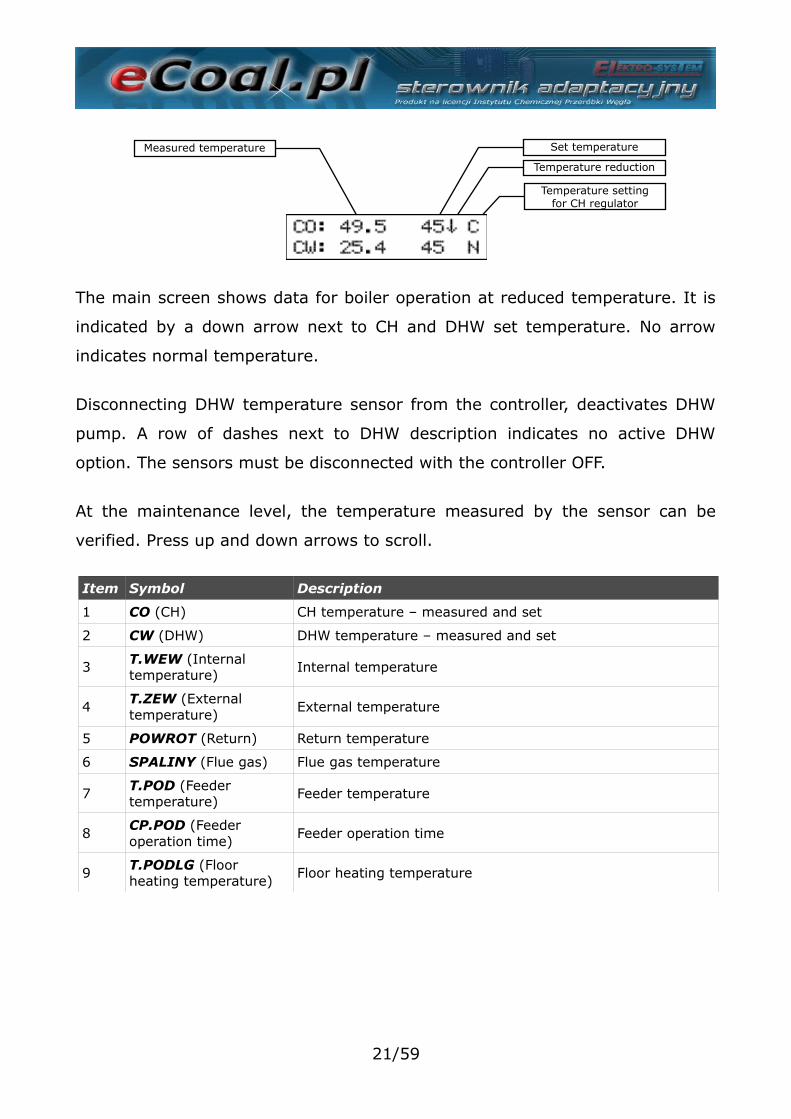
The main screen shows data for boiler operation at reduced temperature. It is
indicated by a down arrow next to CH and DHW set temperature. No arrow
indicates normal temperature.
Disconnecting DHW temperature sensor from the controller, deactivates DHW
pump. A row of dashes next to DHW description indicates no active DHW
option. The sensors must be disconnected with the controller OFF.
At the maintenance level, the temperature measured by the sensor can be
verified. Press up and down arrows to scroll.
Item Symbol Description
1 CO (CH) CH temperature – measured and set
2 CW (DHW) DHW temperature – measured and set
3 T.WEW (Internal temperature)
Internal temperature
4T.ZEW (External temperature)
External temperature
5 POWROT (Return) Return temperature
6 SPALINY (Flue gas) Flue gas temperature
7 T.POD (Feeder temperature)
Feeder temperature
8CP.POD (Feeder operation time)
Feeder operation time
9 T.PODLG (Floor heating temperature)
Floor heating temperature
21/59
Measured temperature Set temperature
Temperature reduction
Temperature settingfor CH regulator
4.3.Controller operation modesThe controller has two operation modes: automatic and manual. Manual mode
is used for lighting off the boiler.
a)Manual modeManual mode can be selected via control panel at the maintenance level or via
controller software (PC/website). To switch the mode on via control panel,
select Tryb Pracy (Operation mode) with left and right arrow and select Tryb
Pracy <ręczny> (Operation mode <manual>). After selecting manual mode,
all devices supplied by the controller may be switched ON/OFF. Hold ESC to
switch to manual mode.
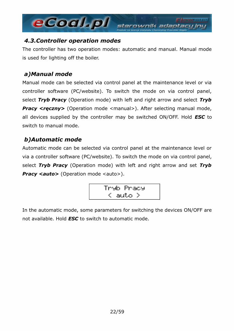
b)Automatic modeAutomatic mode can be selected via control panel at the maintenance level or
via a controller software (PC/website). To switch the mode on via control panel,
select Tryb Pracy (Operation mode) with left and right arrow and set Tryb
Pracy <auto> (Operation mode <auto>).
In the automatic mode, some parameters for switching the devices ON/OFF are
not available. Hold ESC to switch to automatic mode.
22/59
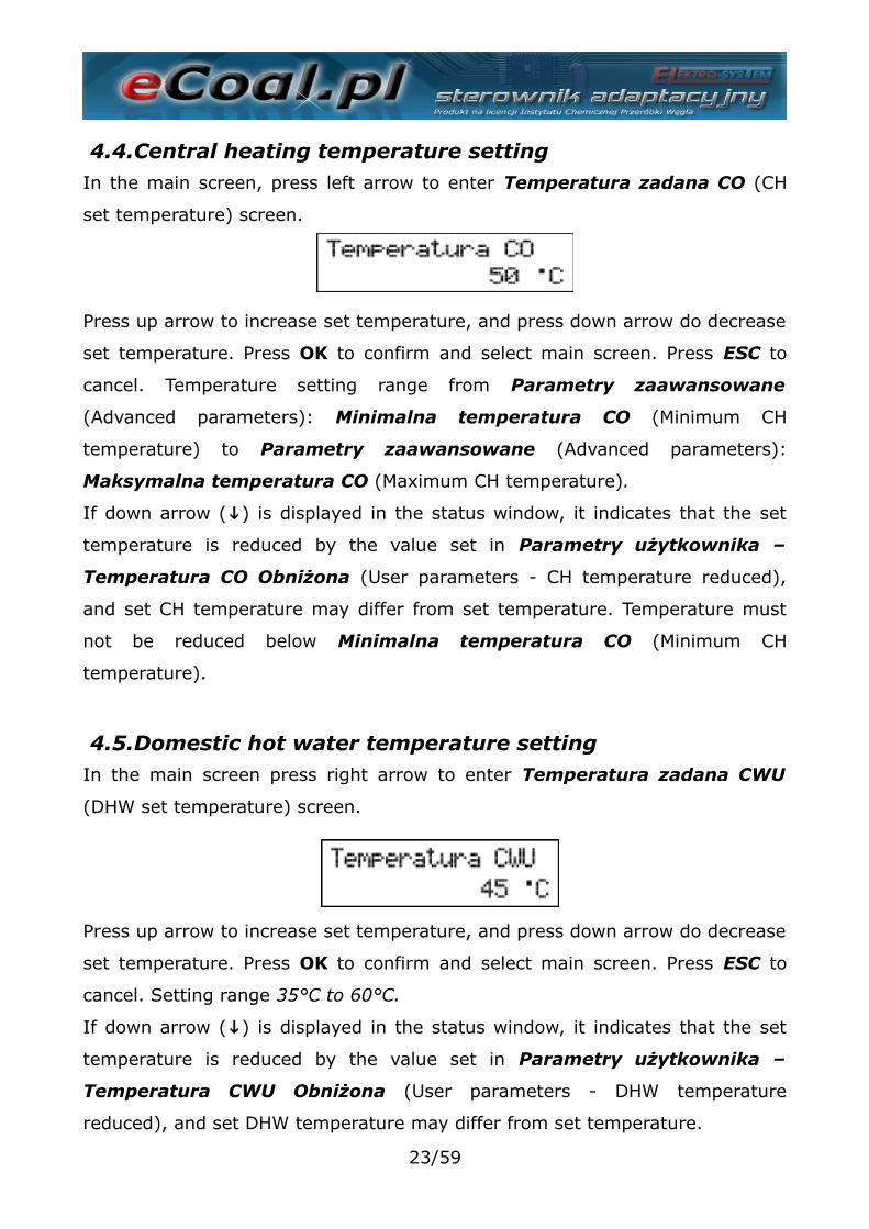
4.4.Central heating temperature settingIn the main screen, press left arrow to enter Temperatura zadana CO (CH
set temperature) screen.
Press up arrow to increase set temperature, and press down arrow do decrease
set temperature. Press OK to confirm and select main screen. Press ESC to
cancel. Temperature setting range from Parametry zaawansowane
(Advanced parameters): Minimalna temperatura CO (Minimum CH
temperature) to Parametry zaawansowane (Advanced parameters):
Maksymalna temperatura CO (Maximum CH temperature).
If down arrow (↓) is displayed in the status window, it indicates that the set
temperature is reduced by the value set in Parametry użytkownika –
Temperatura CO Obniżona (User parameters - CH temperature reduced),
and set CH temperature may differ from set temperature. Temperature must
not be reduced below Minimalna temperatura CO (Minimum CH
temperature).
4.5.Domestic hot water temperature settingIn the main screen press right arrow to enter Temperatura zadana CWU
(DHW set temperature) screen.
Press up arrow to increase set temperature, and press down arrow do decrease
set temperature. Press OK to confirm and select main screen. Press ESC to
cancel. Setting range 35°C to 60°C.
If down arrow (↓) is displayed in the status window, it indicates that the set
temperature is reduced by the value set in Parametry użytkownika –
Temperatura CWU Obniżona (User parameters - DHW temperature
reduced), and set DHW temperature may differ from set temperature.
23/59
4.6.Function - fuel chargeThe controller generates event log entries, and new fuel charge entries. It may
also indicate low fuel level in the hopper based on the feeder operation time
required to empty the fuel hopper. Feeder operation time to hopper emptying
is available via website. Current feeder operation time is displayed in the status
screen (CP.POD item). Press (←→ - left or right arrow) to display prompt to
enter the fuel quantity charged to the hopper ( ↓↑ - up and down arrow).
This function also enables controller registration on eSterownik.pl website to
generate automatic statistics on combusted fuel, related costs and
approximate boiler power.
5.Controller programmingController settings can be changed via control panel. To access the settings,
press and hold OK for 1 second. Select the item and press OK.
5.1.Combustion parametersParametry spalania (Combustion parameters) menu items are changed
depending on combustion algorithm selected in the advanced parameter menu:
Typ podajnika (Feeder type):
•Retorta-ręczny (Retort - manual) – retort feeder, manual combustion
process.
•Retorta-grupowe (Retort - group) – retort feeder, semi-automatic
combustion process.
•Retorta-eCoal (Retort - eCoal) – retort feeder, fully automatic combustion
process.
•Zasypowy (Hopper) – combustion at an emergency grate with feeder OFF.
Select an item and press OK.
Select item with up or down arrow. Press OK to edit item. Press up and down
arrow ( ↓↑ - ) to change value. Press OK to confirm. Press ESC to cancel and
exit.
24/59
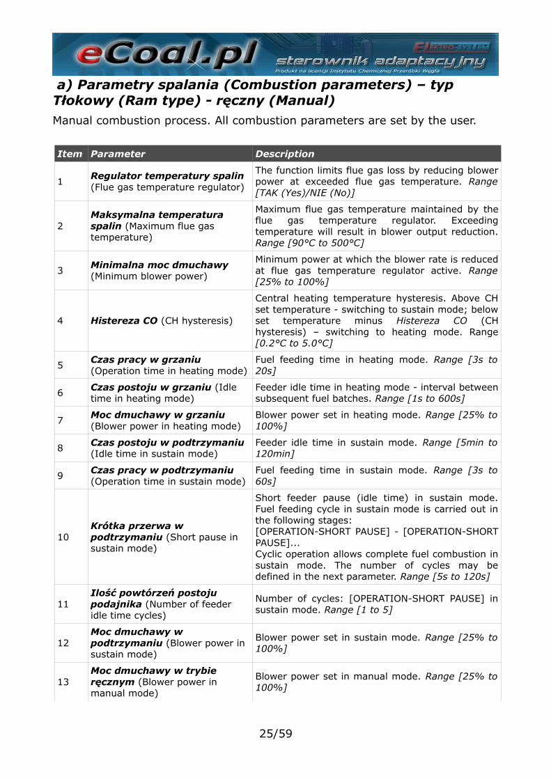
a) Parametry spalania (Combustion parameters) – typ Tłokowy (Ram type) - ręczny (Manual)Manual combustion process. All combustion parameters are set by the user.
Item Parameter Description
1Regulator temperatury spalin (Flue gas temperature regulator)
The function limits flue gas loss by reducing blowerpower at exceeded flue gas temperature. Range[TAK (Yes)/NIE (No)]
2Maksymalna temperatura spalin (Maximum flue gas temperature)
Maximum flue gas temperature maintained by theflue gas temperature regulator. Exceedingtemperature will result in blower output reduction.Range [90°C to 500°C]
3Minimalna moc dmuchawy (Minimum blower power)
Minimum power at which the blower rate is reducedat flue gas temperature regulator active. Range[25% to 100%]
4 Histereza CO (CH hysteresis)
Central heating temperature hysteresis. Above CHset temperature - switching to sustain mode; belowset temperature minus Histereza CO (CHhysteresis) – switching to heating mode. Range[0.2°C to 5.0°C]
5Czas pracy w grzaniu (Operation time in heating mode)
Fuel feeding time in heating mode. Range [3s to20s]
6 Czas postoju w grzaniu (Idle time in heating mode)
Feeder idle time in heating mode - interval betweensubsequent fuel batches. Range [1s to 600s]
7Moc dmuchawy w grzaniu (Blower power in heating mode)
Blower power set in heating mode. Range [25% to100%]
8 Czas postoju w podtrzymaniu (Idle time in sustain mode)
Feeder idle time in sustain mode. Range [5min to120min]
9Czas pracy w podtrzymaniu (Operation time in sustain mode)
Fuel feeding time in sustain mode. Range [3s to60s]
10Krótka przerwa w podtrzymaniu (Short pause in sustain mode)
Short feeder pause (idle time) in sustain mode.Fuel feeding cycle in sustain mode is carried out inthe following stages: [OPERATION-SHORT PAUSE] - [OPERATION-SHORTPAUSE]...Cyclic operation allows complete fuel combustion insustain mode. The number of cycles may bedefined in the next parameter. Range [5s to 120s]
11Ilość powtórzeń postoju podajnika (Number of feeder idle time cycles)
Number of cycles: [OPERATION-SHORT PAUSE] insustain mode. Range [1 to 5]
12Moc dmuchawy w podtrzymaniu (Blower power in sustain mode)
Blower power set in sustain mode. Range [25% to100%]
13Moc dmuchawy w trybie ręcznym (Blower power in manual mode)
Blower power set in manual mode. Range [25% to100%]
25/59
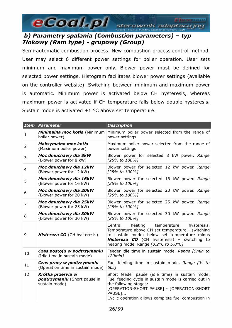
b) Parametry spalania (Combustion parameters) – typ Tłokowy (Ram type) - grupowy (Group)Semi-automatic combustion process. New combustion process control method.
User may select 6 different power settings for boiler operation. User sets
minimum and maximum power only. Blower power must be defined for
selected power settings. Histogram facilitates blower power settings (available
on the controller website). Switching between minimum and maximum power
is automatic. Minimum power is activated below CH hysteresis, whereas
maximum power is activated if CH temperature falls below double hysteresis.
Sustain mode is activated +1 °C above set temperature.
Item Parameter Description
1Minimalna moc kotła (Minimumboiler power)
Minimum boiler power selected from the range ofpower settings
2 Maksymalna moc kotła (Maximum boiler power)
Maximum boiler power selected from the range ofpower settings
3Moc dmuchawy dla 8kW (Blower power for 8 kW)
Blower power for selected 8 kW power. Range[25% to 100%]
4 Moc dmuchawy dla 12kW (Blower power for 12 kW)
Blower power for selected 12 kW power. Range[25% to 100%]
5Moc dmuchawy dla 16kW (Blower power for 16 kW)
Blower power for selected 16 kW power. Range[25% to 100%]
6 Moc dmuchawy dla 20kW (Blower power for 20 kW)
Blower power for selected 20 kW power. Range[25% to 100%]
7Moc dmuchawy dla 25kW (Blower power for 25 kW)
Blower power for selected 25 kW power. Range[25% to 100%]
8 Moc dmuchawy dla 30kW (Blower power for 30 kW)
Blower power for selected 30 kW power. Range[25% to 100%]
9 Histereza CO (CH hysteresis)
Central heating temperature hysteresis.Temperature above CH set temperature - switchingto sustain mode; below set temperature minusHistereza CO (CH hysteresis) – switching toheating mode. Range [0.2°C to 5.0°C]
10Czas postoju w podtrzymaniu (Idle time in sustain mode)
Feeder idle time in sustain mode. Range [5min to120min]
11 Czas pracy w podtrzymaniu (Operation time in sustain mode)
Fuel feeding time in sustain mode. Range [3s to60s]
12 Krótka przerwa w podtrzymaniu (Short pause in sustain mode)
Short feeder pause (idle time) in sustain mode.Fuel feeding cycle in sustain mode is carried out inthe following stages: [OPERATION-SHORT PAUSE] - [OPERATION-SHORTPAUSE]...Cyclic operation allows complete fuel combustion in
26/59
Item Parameter Description
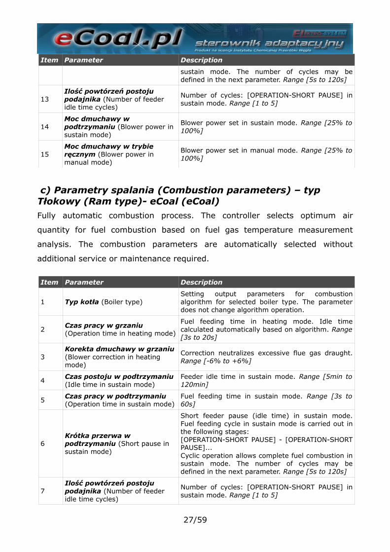
sustain mode. The number of cycles may bedefined in the next parameter. Range [5s to 120s]
13Ilość powtórzeń postoju podajnika (Number of feeder idle time cycles)
Number of cycles: [OPERATION-SHORT PAUSE] insustain mode. Range [1 to 5]
14Moc dmuchawy w podtrzymaniu (Blower power in sustain mode)
Blower power set in sustain mode. Range [25% to100%]
15Moc dmuchawy w trybie ręcznym (Blower power in manual mode)
Blower power set in manual mode. Range [25% to100%]
c) Parametry spalania (Combustion parameters) – typ Tłokowy (Ram type)- eCoal (eCoal)Fully automatic combustion process. The controller selects optimum air
quantity for fuel combustion based on fuel gas temperature measurement
analysis. The combustion parameters are automatically selected without
additional service or maintenance required.
Item Parameter Description
1 Typ kotła (Boiler type)Setting output parameters for combustionalgorithm for selected boiler type. The parameterdoes not change algorithm operation.
2Czas pracy w grzaniu (Operation time in heating mode)
Fuel feeding time in heating mode. Idle timecalculated automatically based on algorithm. Range[3s to 20s]
3Korekta dmuchawy w grzaniu (Blower correction in heating mode)
Correction neutralizes excessive flue gas draught.Range [-6% to +6%]
4Czas postoju w podtrzymaniu (Idle time in sustain mode)
Feeder idle time in sustain mode. Range [5min to120min]
5 Czas pracy w podtrzymaniu (Operation time in sustain mode)
Fuel feeding time in sustain mode. Range [3s to60s]
6Krótka przerwa w podtrzymaniu (Short pause in sustain mode)
Short feeder pause (idle time) in sustain mode.Fuel feeding cycle in sustain mode is carried out inthe following stages: [OPERATION-SHORT PAUSE] - [OPERATION-SHORTPAUSE]...Cyclic operation allows complete fuel combustion insustain mode. The number of cycles may bedefined in the next parameter. Range [5s to 120s]
7Ilość powtórzeń postoju podajnika (Number of feeder idle time cycles)
Number of cycles: [OPERATION-SHORT PAUSE] insustain mode. Range [1 to 5]
27/59
Item Parameter Description
8Moc dmuchawy w podtrzymaniu (Blower power in sustain mode)
Blower power set in sustain mode. Range [25% to100%]
9Moc dmuchawy w trybie ręcznym (Blower power in manual mode)
Blower power set in manual mode. Range [25% to100%]
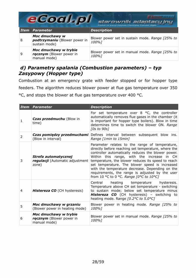
d) Parametry spalania (Combustion parameters) – typ Zasypowy (Hopper type)Combustion at an emergency grate with feeder stopped or for hopper type
feeders. The algorithm reduces blower power at flue gas temperature over 350
°C, and stops the blower at flue gas temperature over 400 °C.
Item Parameter Description
1Czas przedmuchu (Blow in time)
For set temperature over 8 °C, the controllerautomatically removes flue gases in the chamber (itis important for hopper type boilers). Blow in timedetermines time to switch the blower ON. Range[0s to 90s]
2Czas pomiędzy przedmuchami(Blow in interval)
Defines interval between subsequent blow ins.Range [1min to 15min]
3Strefa automatycznej regulacji (Automatic adjustmentzone)
Parameter relates to the range of temperature,directly before reaching set temperature, where thecontroller automatically reduces the blower power.Within this range, with the increase in CHtemperature, the blower reduces its speed to reachset temperature. The blower speed is increasedwith the temperature decrease. Depending on therequirements, the range is adjusted by the userfrom 10 °C to 0 °C. Range [0°C to 10°C]
4 Histereza CO (CH hysteresis)
Central heating temperature hysteresis.Temperature above CH set temperature - switchingto sustain mode; below set temperature minusHistereza CO (CH hysteresis) – switching toheating mode. Range [0.2°C to 5.0°C]
5 Moc dmuchawy w grzaniu (Blower power in heating mode)
Blower power in heating mode. Range [25% to100%]
6Moc dmuchawy w trybie ręcznym (Blower power in manual mode)
Blower power set in manual mode. Range [25% to100%]
28/59
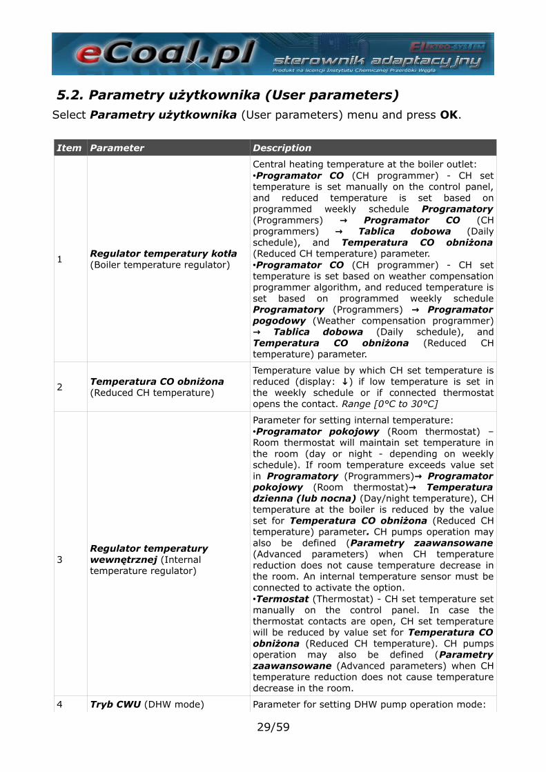
5.2. Parametry użytkownika (User parameters)Select Parametry użytkownika (User parameters) menu and press OK.
Item Parameter Description
1Regulator temperatury kotła (Boiler temperature regulator)
Central heating temperature at the boiler outlet:•Programator CO (CH programmer) - CH settemperature is set manually on the control panel,and reduced temperature is set based onprogrammed weekly schedule Programatory(Programmers) Programator CO → (CHprogrammers) Tablica dobowa → (Dailyschedule), and Temperatura CO obniżona(Reduced CH temperature) parameter.•Programator CO (CH programmer) - CH settemperature is set based on weather compensationprogrammer algorithm, and reduced temperature isset based on programmed weekly scheduleProgramatory (Programmers) Programator→pogodowy (Weather compensation programmer)
Tablica dobowa → (Daily schedule), andTemperatura CO obniżona (Reduced CHtemperature) parameter.
2 Temperatura CO obniżona (Reduced CH temperature)
Temperature value by which CH set temperature isreduced (display: ↓) if low temperature is set inthe weekly schedule or if connected thermostatopens the contact. Range [0°C to 30°C]
3Regulator temperatury wewnętrznej (Internal temperature regulator)
Parameter for setting internal temperature:•Programator pokojowy (Room thermostat) –Room thermostat will maintain set temperature inthe room (day or night - depending on weeklyschedule). If room temperature exceeds value setin Programatory (Programmers) Programator→pokojowy (Room thermostat)→ Temperaturadzienna (lub nocna) (Day/night temperature), CHtemperature at the boiler is reduced by the valueset for Temperatura CO obniżona (Reduced CHtemperature) parameter. CH pumps operation mayalso be defined (Parametry zaawansowane(Advanced parameters) when CH temperaturereduction does not cause temperature decrease inthe room. An internal temperature sensor must beconnected to activate the option.•Termostat (Thermostat) - CH set temperature setmanually on the control panel. In case thethermostat contacts are open, CH set temperaturewill be reduced by value set for Temperatura COobniżona (Reduced CH temperature). CH pumpsoperation may also be defined (Parametryzaawansowane (Advanced parameters) when CHtemperature reduction does not cause temperaturedecrease in the room.
4 Tryb CWU (DHW mode) Parameter for setting DHW pump operation mode:
29/59
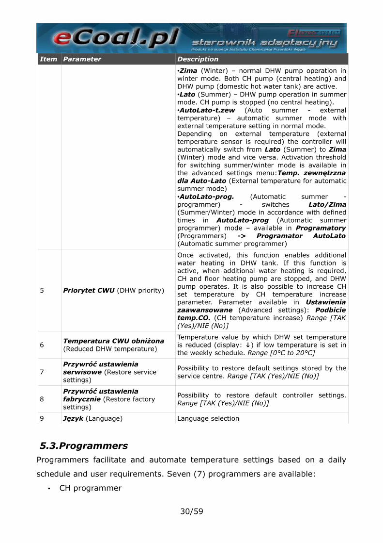
Item Parameter Description
•Zima (Winter) – normal DHW pump operation inwinter mode. Both CH pump (central heating) andDHW pump (domestic hot water tank) are active.•Lato (Summer) – DHW pump operation in summermode. CH pump is stopped (no central heating).•AutoLato-t.zew (Auto summer - externaltemperature) – automatic summer mode withexternal temperature setting in normal mode.Depending on external temperature (externaltemperature sensor is required) the controller willautomatically switch from Lato (Summer) to Zima(Winter) mode and vice versa. Activation thresholdfor switching summer/winter mode is available inthe advanced settings menu:Temp. zewnętrznadla Auto-Lato (External temperature for automaticsummer mode)•AutoLato-prog. (Automatic summer -programmer) - switches Lato/Zima(Summer/Winter) mode in accordance with definedtimes in AutoLato-prog (Automatic summerprogrammer) mode – available in Programatory(Programmers) -> Programator AutoLato(Automatic summer programmer)
5 Priorytet CWU (DHW priority)
Once activated, this function enables additionalwater heating in DHW tank. If this function isactive, when additional water heating is required,CH and floor heating pump are stopped, and DHWpump operates. It is also possible to increase CHset temperature by CH temperature increaseparameter. Parameter available in Ustawieniazaawansowane (Advanced settings): Podbicietemp.CO. (CH temperature increase) Range [TAK(Yes)/NIE (No)]
6Temperatura CWU obniżona (Reduced DHW temperature)
Temperature value by which DHW set temperatureis reduced (display: ↓) if low temperature is set inthe weekly schedule. Range [0°C to 20°C]
7Przywróć ustawienia serwisowe (Restore service settings)
Possibility to restore default settings stored by theservice centre. Range [TAK (Yes)/NIE (No)]
8Przywróć ustawienia fabrycznie (Restore factory settings)
Possibility to restore default controller settings.Range [TAK (Yes)/NIE (No)]
9 Język (Language) Language selection
5.3.ProgrammersProgrammers facilitate and automate temperature settings based on a daily
schedule and user requirements. Seven (7) programmers are available:
• CH programmer
30/59
• DHW programmer
• Weather compensation programmer
• Room temperature programmer
• Circulation pump programmer
• Automatic summer programmer
• Floor heating programmer
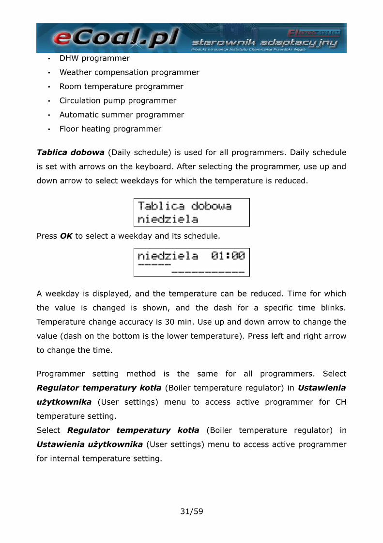
Tablica dobowa (Daily schedule) is used for all programmers. Daily schedule
is set with arrows on the keyboard. After selecting the programmer, use up and
down arrow to select weekdays for which the temperature is reduced.
Press OK to select a weekday and its schedule.
A weekday is displayed, and the temperature can be reduced. Time for which
the value is changed is shown, and the dash for a specific time blinks.
Temperature change accuracy is 30 min. Use up and down arrow to change the
value (dash on the bottom is the lower temperature). Press left and right arrow
to change the time.
Programmer setting method is the same for all programmers. Select
Regulator temperatury kotła (Boiler temperature regulator) in Ustawienia
użytkownika (User settings) menu to access active programmer for CH
temperature setting.
Select Regulator temperatury kotła (Boiler temperature regulator) in
Ustawienia użytkownika (User settings) menu to access active programmer
for internal temperature setting.
31/59
a)Programator CO (CH programmer)Set temperature is set by the user. Reduced CH temperature is set with
Temperatura CO obniżona (Reduced CH temperature) Poziomu ustawień
(Setting level) in Parametry użytkownika (User parameters) menu. Reduced
temperature is used with a correct setting in Tablica dobowa (Daily
schedule).
b)Programator CWU (DHW programmer)The programmer sets temperature for domestic hot water. Reduced DHW
temperature is set with Temperatura CWU obniżona (Reduced DHW
temperature) Poziomu ustawień (Setting level) in Parametry użytkownika
(User parameters) menu. Reduced temperature is used with a correct setting
in Tablica dobowa (Daily schedule).
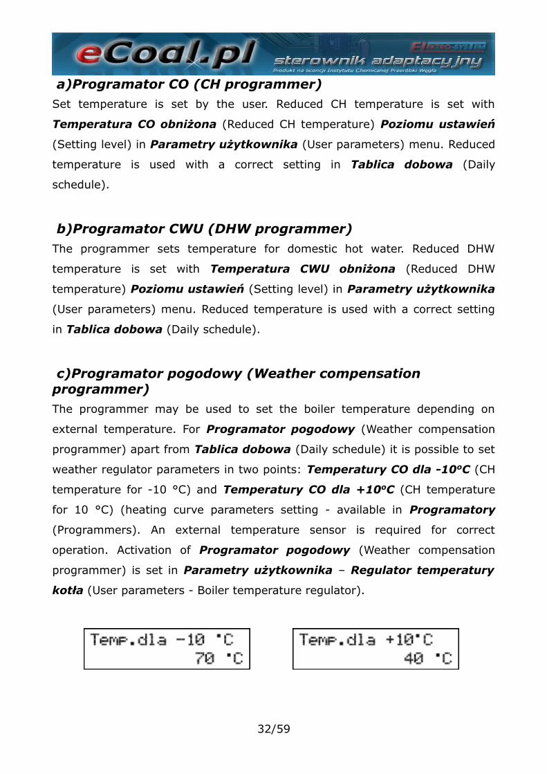
c)Programator pogodowy (Weather compensation programmer)The programmer may be used to set the boiler temperature depending on
external temperature. For Programator pogodowy (Weather compensation
programmer) apart from Tablica dobowa (Daily schedule) it is possible to set
weather regulator parameters in two points: Temperatury CO dla -10oC (CH
temperature for -10 °C) and Temperatury CO dla +10oC (CH temperature
for 10 °C) (heating curve parameters setting - available in Programatory
(Programmers). An external temperature sensor is required for correct
operation. Activation of Programator pogodowy (Weather compensation
programmer) is set in Parametry użytkownika – Regulator temperatury
kotła (User parameters - Boiler temperature regulator).
32/59
d)Programator pokojowy (Room programmer)The programmer selects boiler temperature depending on the conditions in the
room. Room temperature programmer requires installation of internal
temperature sensor. Activation of Programator pokojowy (Room
temperature thermostat) is set in Parametry użytkownika – Regulator
temperatury wewnętrznej (User parameters - Internal temperature
regulator): Pokojowy (Room).
If internal temperature exceeds set value of the programmer, set temperature
is reduced by the CH temperature decrease value. Additionally CH pump may
operate in three (3) modes: Continuous, cyclic and OFF. CH pump operation
mode after reaching set temperature is set in Ustawienia zaawansowane
(Advanced settings): Tryb pracy pompy CO dla reg. wewnętrznego (CH
pump operation mode for internal temperature regulator). For cyclic CH pump
operation, operation and idle time are set with the following parameters: Czas
pracy pompy CO dla reg.wew (CH pump operation time for internal
temperature regulator) and Czas postoju pompy CO dla reg.wew. (CH idle
time for internal temperature regulator). The settings also apply to active
thermostat.
Item Parameter Description
1 Temperatura dzienna (Day temperature)
Day temperature maintained in the room. Range [5°Cto 35°C]
2Temperatura nocna (Night temperature)
Night temperature maintained in the room. Range[5°C to 35°C]
3 Histereza (Hysteresis)The parameter determines value by which the internaltemperature is reduced, to start the room heatingprocedure. Range [0.1°C to 2.0°C]
4Tablica dobowa (Daily schedule)
Daily schedule to set time intervals for day and nighttemperature. Upper dash – day temperature, bottomdash – night temperature.
33/59
e)Programator pompy cyrkulacyjnej (Circulation pump programmer)In case of DHW circulation pump activation, it is possible to set time intervals
for pump activation. Time intervals are defined in Tablica tygodniowa
(Weekly schedule - top dash - pump ON, bottom dash - pump OFF).
Item Parameter Description
1Czas pracy pompy cyrkulacyjnej (Circulation pump operation time)
Parameter determines circulation pump operationtime (operation - idle - operation - idle ...), if pumpoperation is set in the programmer (top bar). Range[1min to 60min]
2Czas postoju pompy cyrkulacyjnej (Circulation pump idle time)
Parameter determines circulation pump idle time(operation - idle - operation - idle ...), if pumpoperation is set in the programmer (top dash).Range [0min to 60min]
3
Temperatura załączenia pompy cyrkulacyjnej (Circulation pump activation temperature)
Minimum DHW temperature above which thecirculation pump may operate. Circulation pump isstopped after DHW temperature is reduced by 0.5°C. Range [25°C to 60°C]
4Praca auto w trybie ręcznym (Automatic operationin manual mode)
Parameter enables automatic circulation pumpoperation in manual mode. Range [TAK (Yes)/NIE(No)]
5Tablica dobowa (Daily schedule)
Weekly daily schedule to set time circulation pumpoperation intervals.
f)Programator Auto-Lato (Automatic summer programmer)If Auto-Lato-prog (Automatic summer programmer) mode is set for Tryb
Pracy CWU (DHW operation mode) you can set intervals to activate summer
or winter mode. Time intervals are defined in Tablica tygodniowa (Weekly
schedule - top dash - summer mode, bottom dash - winter mode).
g)Programator ogrzewania podłogowego (Floor heating programmer)It selects floor heating temperature depending on the conditions in the room.
Programmer requires floor heating temperature sensor installation.
Programator podłogowy (Floor heating programmer) is activated in
Parametry zaawansowane (Advanced parameters) – Funkcja pompy
mieszającej (Mixing pump function): Podłogowa (Floor heating).
34/59
Item Parameter Description
1Temperatura dzienna (Day temperature)
Day temperature maintained in the room. Range [5°C to35°C]
2 Temperatura nocna (Night temperature)
Night temperature maintained in the room. Range [5°Cto 35°C]
3 Histereza (Hysteresis)
The parameter determines value by which thetemperature in a room with floor heating is reduced, tostart the room heating procedure. Range [0.2°C to5.0°C]
4Czas pracy pompy podłogowej (Floor heating pump operation time)
If temperature is reached, floor heating pump switchesto cyclic operation mode. The parameter determinesfloor heating pump operation time. Time set to 0 stopsthe pump after reaching set floor heating temperature.Range [0min to 60min]
5Czas postoju pompy podłogowej (Floor heating pump idle time)
If temperature is reached, floor heating pump switchesto cyclic operation mode. The parameter specifies floorheating pump idle time. Time set to 0 results incontinuous pump operation, even if set floor heatingtemperature is reached. Range [0min to 60min]
6Tablica dobowa (Daily schedule)
Daily schedule to set time intervals for day and nighttemperature. Upper dash – day temperature, bottomdash – night temperature.
5.4.InternetIt enables parameter setting to connect with the controller via Internet. It
requires internet module installed and configuration of required parameters.
Item Parameter Description
1 Adres IP (IP address) Controller IP address as displayed in the local network
2 Maska (Mask) Subnet mask used in a local computer network.
3 Brama (Gateway) The default gateway used in a local computer network.
4Zdalny serwer (Remote server)
Shall the controller connect with a remote server?Remote server enables controller connection via website,to change parameters, view graphs, and to carry outgeneral controller maintenance. Public IP address is notrequired for the proxy server. More onhttp://eSterownik.pl Zdalny dostęp (Remote access)tab
5Adres serwera (Server address)
Proxy server IP address. Server address is alwaysavailable on http://eSterownik.pl during registration of anew controller – Zdalny dostęp tab
6 Port serwera (Server port)Proxy server port. Server port is always availableonhttp://eSterownik.pl during registration of a newcontroller – Zdalny dostęp tab
7 Identyfikator (Identifier)Unique controller identifier. Identifier is generatedautomatically during registration of a new controlleronhttp://eSterownik.pl website – Zdalny dostęp tab
35/59
Item Parameter Description
8Reset haseł (Password reset)
Setting default passwords for website access.Read only - user: user, password: userAdministrator rights – user: admin, password: admin
5.5.Data i czas (Date and time)Time settings ensuring correct programmer operation. After selecting Data i
czas (Date and time), a window with time set for the controller is displayed.
Change time with up and down arrows. Select date items with right and left
arrows.
5.6.Parametry zaawansowane (Advanced parameters)Used for boiler installation settings.
Item Parameter Description
1Typ podajnika (Feeder type)
Feeder operation mode (combustion algorithm):
- Retorta-ręczny (Retort - manual) – retort feeder,manual combustion process. Combustion parametersavailable in Parametry spalania (Combustionparameters) menu.
- Retorta-grupowe (Retort - group) – retort feeder,semi-automatic combustion process. Combustionparameters available in Parametry spalania(Combustion parameters) menu.
- Retorta-eCoal (Retort - eCoal) – retort feeder, fullyautomatic combustion process. Combustion parametersavailable in Parametry spalania (Combustionparameters) menu.
- Zasypowy (Hopper) – combustion at an emergencygrate. Combustion parameters available in Parametryspalania (Combustion parameters) menu.
2Minimalna temperatura CO (Minimum CH temperature)
User defined CH set temperature limit. This parameteralso defines CH temperature, at which CH pump isactivated. CH pump activation threshold reduced by 2 °Cfrom set value. CH pump deactivation 4 °C below setvalue. Range [42°C to 60°C]
3 Maksymalna temperatura User defined CH set temperature limit. This parameter
36/59
Item Parameter Description
CO (Maximum CH temperature)
also defines CH temperature, at which CH pump isactivated (e.g. when room thermostat algorithm forcesCO pump to deactivate). Range [65°C to 80°C]
4 CH pump operation mode for internal regulator
Parameter determines CH pump operation with activeroom thermostat/thermostat. After room temperature isreached, CH pump may operate in three (3) modes:
- Ciągła (Continous) – always ON – reduced CH settemperature after reaching set temperature in the room– CH pump does not stop.- Cykliczna (Cyclic) – CH pump operates in cyclic modewith set operation/idle time intervals - parameter 5 and6 - after reaching set temperature in the room.- Wyłączona (OFF) – CH pump is stopped after reachingset temperature in the room.
5Czas pracy pompy CO (CHpump operation time)
Parameter determines CH pump operation time for activeroom temperature thermostat/thermostat anddetermined CH pump cyclic operation - parameter 4.Range [1min to 99min]
6 Czas postoju pompy CO (CH pump idle time)
Parameter determines CH pump idle time for active roomtemperature thermostat/thermostat and determined CHpump cyclic operation - parameter 4. Range [1min to99min]
7Funkcja wyjścia pompy CWU (DHW pump output function)
DHW pump operation mode:- CWU (DHW) – DHW pump is used as a pump for fillingthe domestic hot water tank- CWU + miesz (DHW + mixing) – DHW pump functionsas a pump for filling the domestic hot water tank andmixing pump and a mixing pump returning the water tothe boiler through DHW exchanger (short circuit). Thisfunction enables use of mixing pump output to connectcirculation pump or floor heating pump.
8Histereza CWU (DHW hysteresis)
DHW temperature hysteresis. Above set DHWtemperature – deactivated DHW pump, below DHW settemperature minus Histereza CWU (DHW hysteresis) –DHW pump is activated. Range [0.2°C to 5.0°C]
9
Podbicie temp. CO przy priorytecie CWU (CH temp. increase in DHW priority mode)
Parameter determines °C, the CH set temperature isincreased in Priorytet CWU (DHW priority) mode ifwater requires heating. Range [0°C to 10°C]
10
Temperatura zewnętrzna dla Auto-Lato (External temperature for automatic summer mode)
External temperature, at which the controller switchesfrom summer to winter mode. For correctAutoLato-temp. (Automatic summer - temperature)mode operation, external temperature sensor isrequired, and Tryb pracy CWU (DHW operation mode):AutoLato-temp (Automatic summer temperature) setRange [0°C to 25°C]
11Histereza Auto-Lato (Automatic summer mode hysteresis)
Parameter determines hysteresis of switching fromsummer to winter mode in Auto-Lato-temp. (Automaticsummer - temperature) mode Range [0.5°C to 5.0°C]
12 Funkcja pompy Pump operation mode selection:
37/59
Item Parameter Description
mieszającej (Mixing pump function)
- pompa mieszająca (mixing pump) – functionmaintaining minimum return water temperature- pompa cyrkulacyjna (circulation pump) – functionensures continuous circulation of domestic hot waterfrom the heater to the tap- pompa podłogowa (floor heating pump) – floorheating function. Temperature sensor connected to theterminals: Floor heating sensor.
13Niezależna praca pompy mieszającej (Independent mixing pump operation).
Items:- Nie (No) – Normal mixing pump operation dependingon CH pump operation- Tak (Yes) – Mixing pump operates irrespective of CHpump - mixing pump operation in summer modeavailable (with CH pump stopped).
14
Temperatura załączenia pompy mieszającej (Mixing pump activation temperature)
Minimum return water temperature, below which themixing pump is activated. Mixing pump is deactivated, ifreturn temperature is increased by 0.5 °C. Range [25°Cto 60°C]
15Maksymalna temp. podajnika (Maximum feeder temperature)
Setting maximum feeder temperature. Feeder alarm isactivated above set temperature. Fuel is removed fromthe furnace if alarm is activated. Fuel removal time is setwith the next parameter. Range [40°C to 110°C]
16Czas wyrzutu paliwa (Fuelremoval time)
Parameter determines feeder activation time afterZapłon paliwa w podajniku (Fuel ignition in thefeeder) alarm is activated. Fuel is removed from thefurnace to the ash pan for a set time. Range [1min to10min]
17Algorytm wygaszenia kotła (Boiler put out algorithm)
Boiler put out algorithm in sustain and heating mode,based on flue gas temperature:
- Nieaktywny (Inactive) - boiler put out detectiondeactivated in heating and sustain mode. In case theboiler is put out, no alarm is generated and operation isnot stopped.- Tylko grzanie (Heating only) - boiler put out detectionin heating mode only.- Tylko podtrzymanie (Sustain only) – boiler put outdetection in sustain mode only.- Aktywny (Active) – boiler put put detection in heatingand sustain mode.
18* Alarm zewnętrzny * (External alarm)
Potential free contact connected to Alarm zewnętrzny(External alarm) input signalling external events in theboiler room, depending on connected device, e.g. hopperhatch open, smoke detector active or increased carbonmonoxide concentration.
19* Alarm zewnętrzny * – Czas opóźnienia (External alarm – Delay time)
Delay time, after which the external alarm is generated.Range [0s to 600s]
20
* Alarm zewnętrzny * –Inwersja wejścia (External alarm – Input inversion)
Possibility to set a reverse logic for alarm input. Range[TAK (Yes)/NIE (No)]
38/59
Item Parameter Description
21
* Alarm zewnętrzny * –Zatrzymanie po alarmie (External alarm – Stop after alarm)
The controller can be stopped (switching from manualmode with feeder and blower OFF) after external alarmis generated. Range [TAK (Yes)/NIE (No)]
22Zapis ustawień serwisowych (Save servicesettings)
Restore all controller settings as service settings. InParametry użytkownika (User parameters) menu theparameters can be restored: Range [TAK (Yes)/NIE(No)]
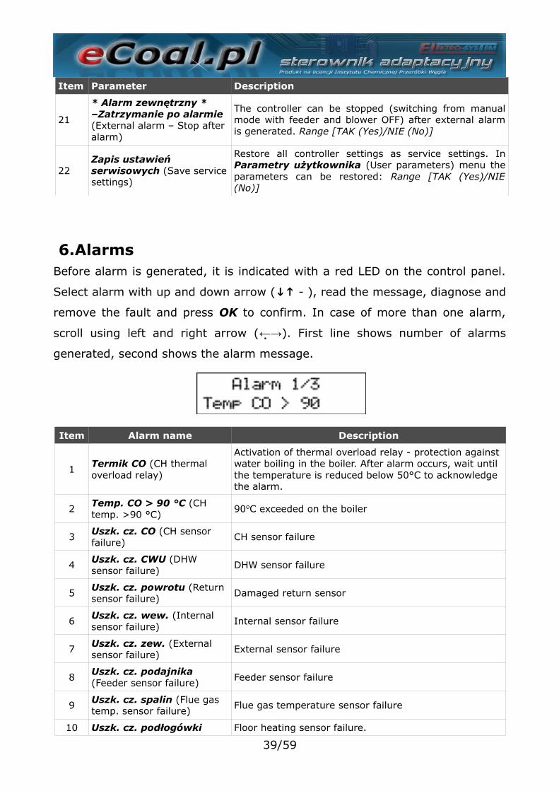
6.AlarmsBefore alarm is generated, it is indicated with a red LED on the control panel.
Select alarm with up and down arrow ( ↓↑ - ), read the message, diagnose and
remove the fault and press OK to confirm. In case of more than one alarm,
scroll using left and right arrow (←→). First line shows number of alarms
generated, second shows the alarm message.
Item Alarm name Description
1Termik CO (CH thermal overload relay)
Activation of thermal overload relay - protection against water boiling in the boiler. After alarm occurs, wait until the temperature is reduced below 50°C to acknowledge the alarm.
2Temp. CO > 90 °C (CH temp. >90 °C)
90oC exceeded on the boiler
3 Uszk. cz. CO (CH sensor failure)
CH sensor failure
4Uszk. cz. CWU (DHW sensor failure)
DHW sensor failure
5 Uszk. cz. powrotu (Return sensor failure)
Damaged return sensor
6Uszk. cz. wew. (Internal sensor failure)
Internal sensor failure
7 Uszk. cz. zew. (External sensor failure)
External sensor failure
8Uszk. cz. podajnika (Feeder sensor failure)
Feeder sensor failure
9 Uszk. cz. spalin (Flue gas temp. sensor failure)
Flue gas temperature sensor failure
10 Uszk. cz. podłogówki Floor heating sensor failure.
39/59

Item Alarm name Description
(Floor heating sensor failure)
11Zapłon paliwa (Fuel ignition)
Fuel ignition in the feeder – exceeding set temperature in the feeder – set Czas wyrzutu paliwa [min] (Fuel removal time) parameter for this alarm
12Wysoka temp. podajnika (High feeder temperature)
Excessive feeder temperature – indicates high feeder temperature, without stopping the feeder. If temperature on the feeder increases by 5°C, Zapłon paliwa (Fuel ignition) alarm is activated.
13Kocioł wygaszony (Boiler put out)
Boiler is put out – alarm in sustain and heating mode. Alarm is activated:- in heating mode - if flue gas temp. in 30 min. will not exceed 50 °C. Check boiler for impurities- sustain mode – in sustain mode, flue gas temperature will not rise by 5 °C. Incorrect sustain mode parameters
14 Wyczyść kocioł (Clean the boiler)
Boiler is dirty – check heat exchanger and flue for impurities
15Wysoka t.spalin (High flue gas temperature)
Excessive flue gas temperature – check correct installation of boiler heat exchanger components
16 Konflikt adr.IP (Incorrect IP address)
Incorrect IP address – IP address is used by another device
17Błąd pamięci EEPROM (EEPROM memory error)
Controller memory error – restore factory settings
18 Alarm zewnętrzny (External alarm)
KONT contact shorted on the controller board - universal alarm input
19Pusty zasobnik (Hopper empty)
Low fuel level in the hopper – alarm does not stop boileroperation. It provides fuel combustion statistics
7.Proxy software - eCoal.plA software providing a proxy server for RS232 port and a web server is
available for controller management via RS232 port.
To manage eCoal.pl controller via website, with RS232 port:
•Download software from eCoal.pl, Wsparcie (Support) tab: eCoalWWWProxy
and run,
•Define COM port used for controller connection,
•Define login, password and local port for web server operation (example:
8080),
•Press Start to run server.
40/59
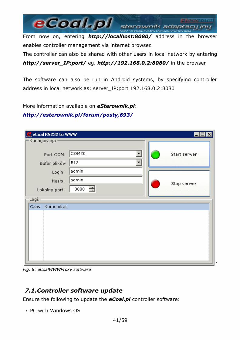
From now on, entering http://localhost:8080/ address in the browser
enables controller management via internet browser.
The controller can also be shared with other users in local network by entering
http://server_IP:port/ eg. http://192.168.0.2:8080/ in the browser
The software can also be run in Android systems, by specifying controller
address in local network as: server_IP:port 192.168.0.2:8080
More information available on eSterownik.pl:
http://esterownik.pl/forum/posty,693/
7.1.Controller software updateEnsure the following to update the eCoal.pl controller software:
• PC with Windows OS
41/59
Fig. 8: eCoalWWWProxy software
• serial port or USB/RS232 adapter
• RS232 cable delivered with a controller
• latest software downloaded from http://eCoal.pl Wsparcie (Support) tab:
4. Controller updater
Due to continuous development and improvements of eCoal.pl controller, test
software builds are regularly made available. Test builds include numerous
amendments and new functions. Controller updater software is available on:
http://esterownik.pl/forum/posty,33
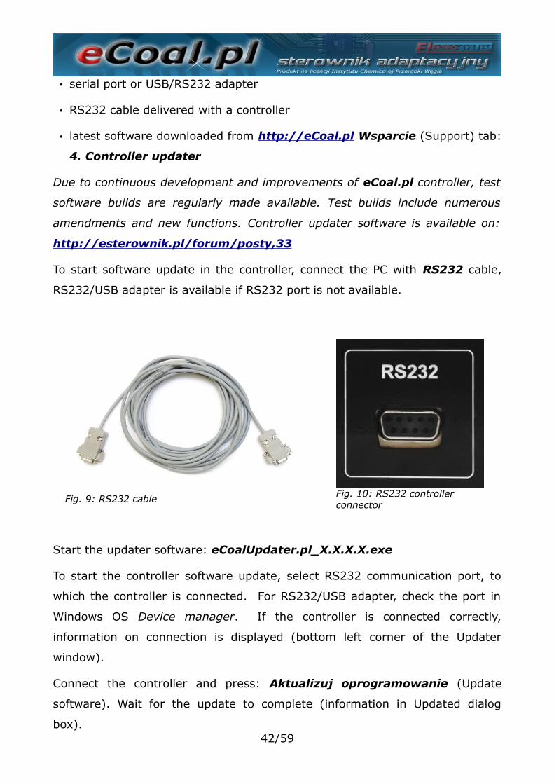
To start software update in the controller, connect the PC with RS232 cable,
RS232/USB adapter is available if RS232 port is not available.
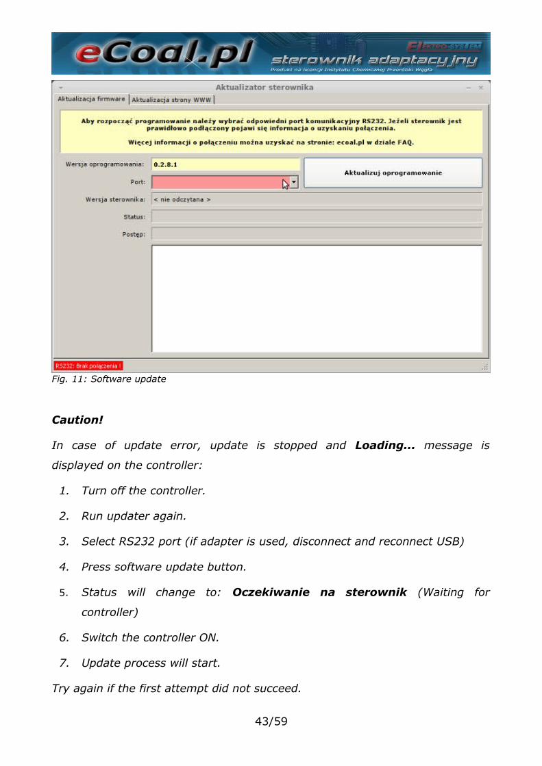
Start the updater software: eCoalUpdater.pl_X.X.X.X.exe
To start the controller software update, select RS232 communication port, to
which the controller is connected. For RS232/USB adapter, check the port in
Windows OS Device manager. If the controller is connected correctly,
information on connection is displayed (bottom left corner of the Updater
window).
Connect the controller and press: Aktualizuj oprogramowanie (Update
software). Wait for the update to complete (information in Updated dialog
box).42/59
Fig. 9: RS232 cable Fig. 10: RS232 controller connector
Caution!
In case of update error, update is stopped and Loading... message is
displayed on the controller:
1. Turn off the controller.
2. Run updater again.
3. Select RS232 port (if adapter is used, disconnect and reconnect USB)
4. Press software update button.
5. Status will change to: Oczekiwanie na sterownik (Waiting for
controller)
6. Switch the controller ON.
7. Update process will start.
Try again if the first attempt did not succeed.
43/59
Fig. 11: Software update
Update process does not allow controller failure due to software update.
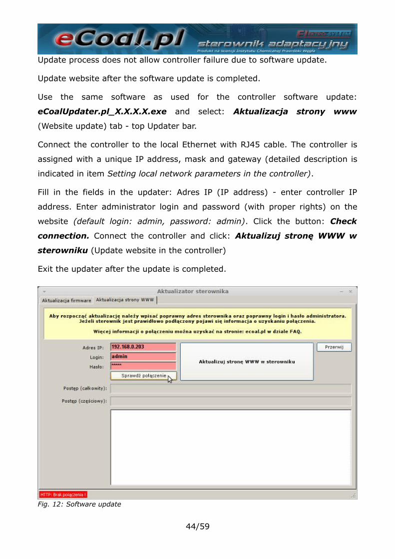
Update website after the software update is completed.
Use the same software as used for the controller software update:
eCoalUpdater.pl_X.X.X.X.exe and select: Aktualizacja strony www
(Website update) tab - top Updater bar.
Connect the controller to the local Ethernet with RJ45 cable. The controller is
assigned with a unique IP address, mask and gateway (detailed description is
indicated in item Setting local network parameters in the controller).
Fill in the fields in the updater: Adres IP (IP address) - enter controller IP
address. Enter administrator login and password (with proper rights) on the
website (default login: admin, password: admin). Click the button: Check
connection. Connect the controller and click: Aktualizuj stronę WWW w
sterowniku (Update website in the controller)
Exit the updater after the update is completed.
44/59
Fig. 12: Software update
Website can also be loaded from the .zip archive directly onto the SD card.
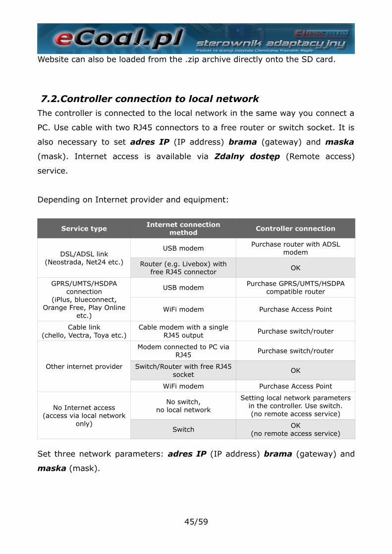
7.2.Controller connection to local networkThe controller is connected to the local network in the same way you connect a
PC. Use cable with two RJ45 connectors to a free router or switch socket. It is
also necessary to set adres IP (IP address) brama (gateway) and maska
(mask). Internet access is available via Zdalny dostęp (Remote access)
service.
Depending on Internet provider and equipment:
Service type Internet connectionmethod
Controller connection
DSL/ADSL link(Neostrada, Net24 etc.)
USB modemPurchase router with ADSL
modem
Router (e.g. Livebox) withfree RJ45 connector
OK
GPRS/UMTS/HSDPAconnection
(iPlus, blueconnect,Orange Free, Play Online
etc.)
USB modemPurchase GPRS/UMTS/HSDPA
compatible router
WiFi modem Purchase Access Point
Cable link(chello, Vectra, Toya etc.)
Cable modem with a singleRJ45 output
Purchase switch/router
Other internet provider
Modem connected to PC viaRJ45
Purchase switch/router
Switch/Router with free RJ45socket
OK
WiFi modem Purchase Access Point
No Internet access(access via local network
only)
No switch,no local network
Setting local network parametersin the controller. Use switch.(no remote access service)
Switch OK(no remote access service)
Set three network parameters: adres IP (IP address) brama (gateway) and
maska (mask).
45/59
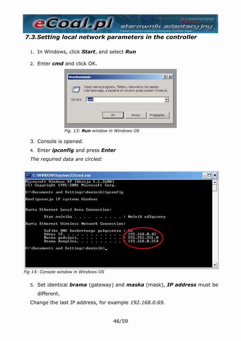
7.3.Setting local network parameters in the controller
1. In Windows, click Start, and select Run
2. Enter cmd and click OK.
3. Console is opened.
4. Enter ipconfig and press Enter
The required data are circled:
5. Set identical brama (gateway) and maska (mask), IP address must be
different.
Change the last IP address, for example 192.168.0.69.
46/59
Fig. 13: Run window in Windows OS
Fig. 14: Console window in Windows OS
Fig 14: Console window in Windows OS
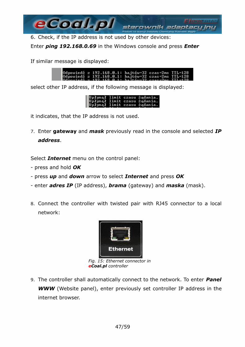
6. Check, if the IP address is not used by other devices:
Enter ping 192.168.0.69 in the Windows console and press Enter
If similar message is displayed:
select other IP address, if the following message is displayed:
it indicates, that the IP address is not used.
7. Enter gateway and mask previously read in the console and selected IP
address.
Select Internet menu on the control panel:
- press and hold OK
- press up and down arrow to select Internet and press OK
- enter adres IP (IP address), brama (gateway) and maska (mask).
8. Connect the controller with twisted pair with RJ45 connector to a local
network:
9. The controller shall automatically connect to the network. To enter Panel
WWW (Website panel), enter previously set controller IP address in the
internet browser.
47/59
Fig. 15: Ethernet connector in eCoal.pl controller
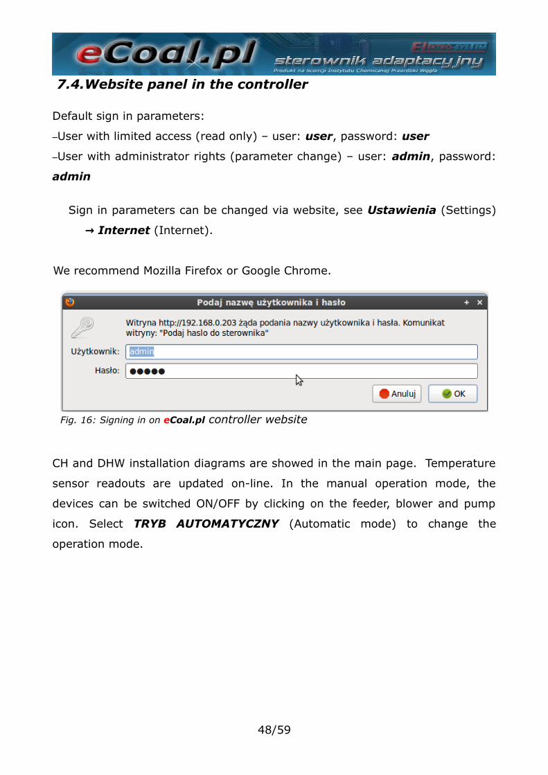
7.4.Website panel in the controller
Default sign in parameters:
–User with limited access (read only) – user: user, password: user
–User with administrator rights (parameter change) – user: admin, password:
admin
Sign in parameters can be changed via website, see Ustawienia (Settings)
Internet → (Internet).
We recommend Mozilla Firefox or Google Chrome.
CH and DHW installation diagrams are showed in the main page. Temperature
sensor readouts are updated on-line. In the manual operation mode, the
devices can be switched ON/OFF by clicking on the feeder, blower and pump
icon. Select TRYB AUTOMATYCZNY (Automatic mode) to change the
operation mode.
48/59
Fig. 16: Signing in on eCoal.pl controller website
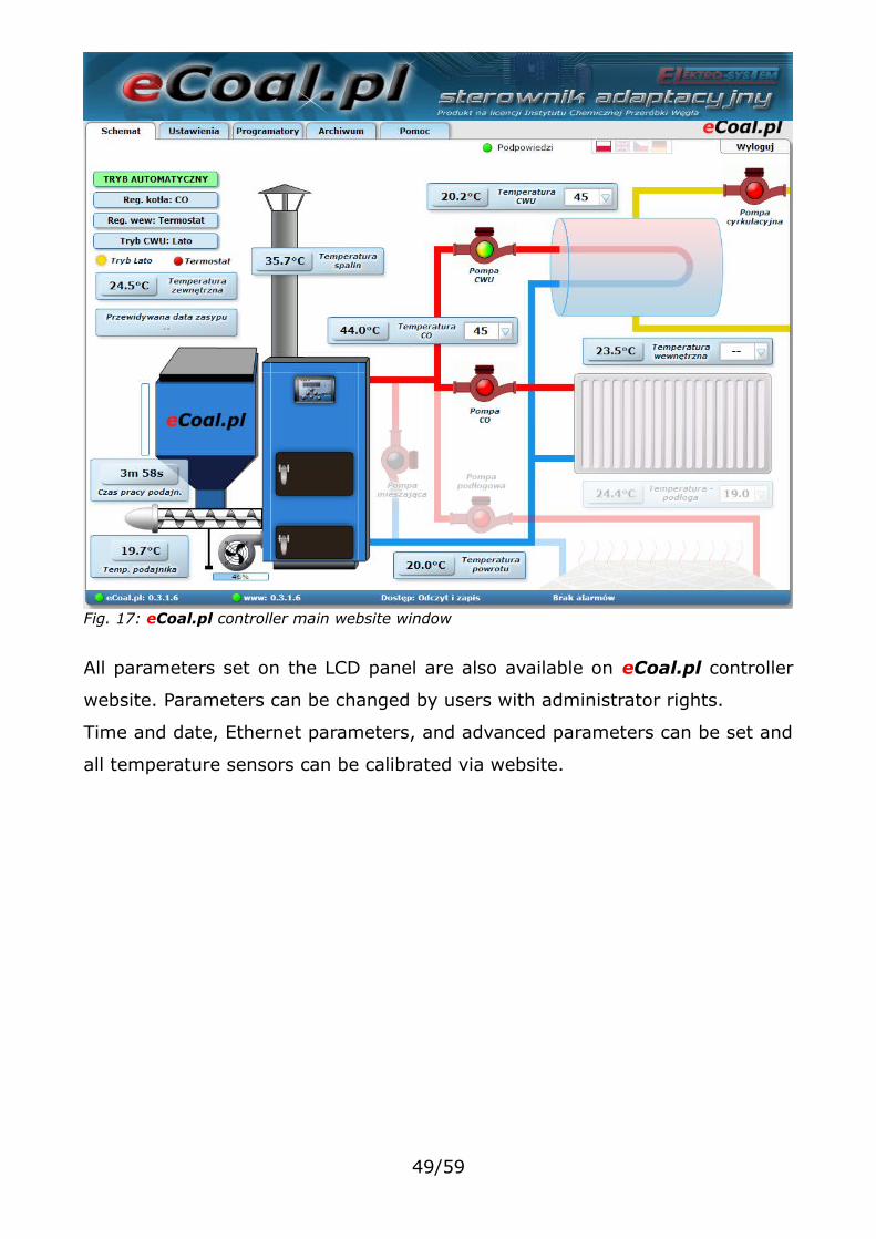
All parameters set on the LCD panel are also available on eCoal.pl controller
website. Parameters can be changed by users with administrator rights.
Time and date, Ethernet parameters, and advanced parameters can be set and
all temperature sensors can be calibrated via website.
49/59
Fig. 17: eCoal.pl controller main website window
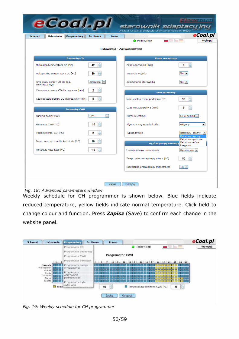
Weekly schedule for CH programmer is shown below. Blue fields indicate
reduced temperature, yellow fields indicate normal temperature. Click field to
change colour and function. Press Zapisz (Save) to confirm each change in the
website panel.
50/59
Fig. 18: Advanced parameters window
Fig. 19: Weekly schedule for CH programmer
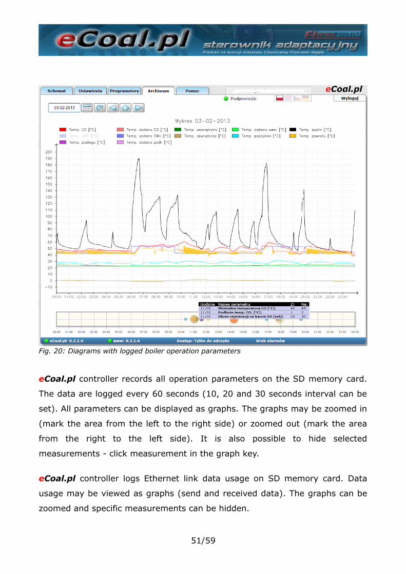
eCoal.pl controller records all operation parameters on the SD memory card.
The data are logged every 60 seconds (10, 20 and 30 seconds interval can be
set). All parameters can be displayed as graphs. The graphs may be zoomed in
(mark the area from the left to the right side) or zoomed out (mark the area
from the right to the left side). It is also possible to hide selected
measurements - click measurement in the graph key.
eCoal.pl controller logs Ethernet link data usage on SD memory card. Data
usage may be viewed as graphs (send and received data). The graphs can be
zoomed and specific measurements can be hidden.
51/59
Fig. 20: Diagrams with logged boiler operation parameters
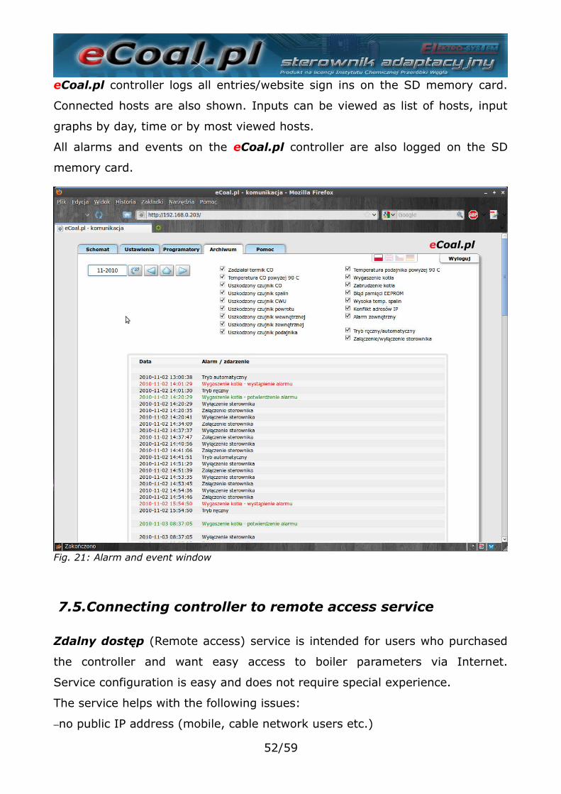
eCoal.pl controller logs all entries/website sign ins on the SD memory card.
Connected hosts are also shown. Inputs can be viewed as list of hosts, input
graphs by day, time or by most viewed hosts.
All alarms and events on the eCoal.pl controller are also logged on the SD
memory card.
7.5.Connecting controller to remote access service
Zdalny dostęp (Remote access) service is intended for users who purchased
the controller and want easy access to boiler parameters via Internet.
Service configuration is easy and does not require special experience.
The service helps with the following issues:
–no public IP address (mobile, cable network users etc.)
52/59
Fig. 21: Alarm and event window
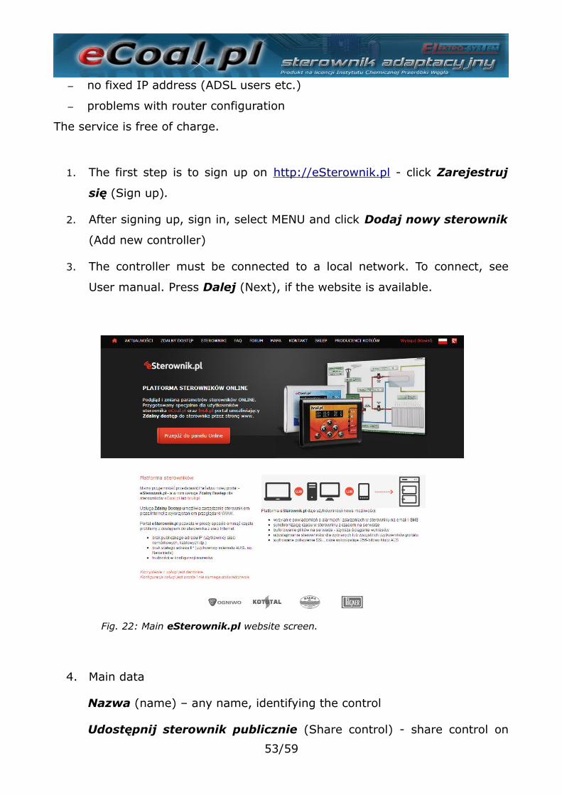
– no fixed IP address (ADSL users etc.)
– problems with router configuration
The service is free of charge.
1. The first step is to sign up on http://eSterownik.pl - click Zarejestruj
się (Sign up).
2. After signing up, sign in, select MENU and click Dodaj nowy sterownik
(Add new controller)
3. The controller must be connected to a local network. To connect, see
User manual. Press Dalej (Next), if the website is available.
Fig. 22: Main eSterownik.pl website screen.
4. Main data
Nazwa (name) – any name, identifying the control
Udostępnij sterownik publicznie (Share control) - share control on
53/59
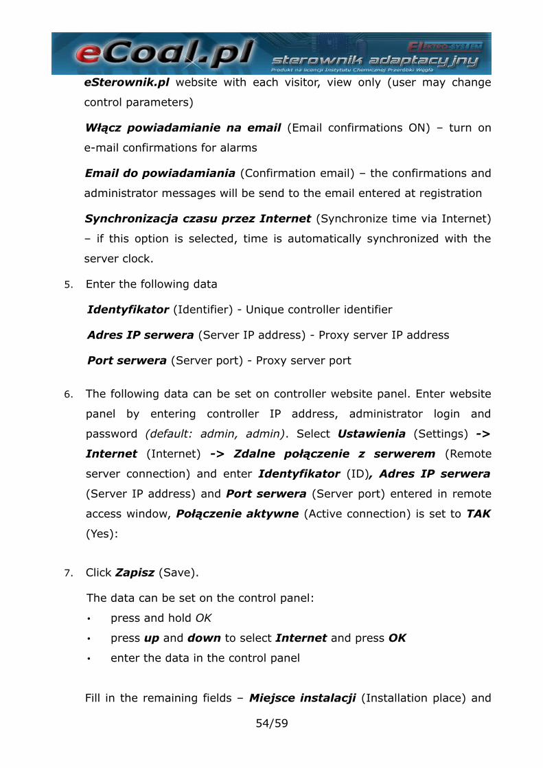
eSterownik.pl website with each visitor, view only (user may change
control parameters)
Włącz powiadamianie na email (Email confirmations ON) – turn on
e-mail confirmations for alarms
Email do powiadamiania (Confirmation email) – the confirmations and
administrator messages will be send to the email entered at registration
Synchronizacja czasu przez Internet (Synchronize time via Internet)
– if this option is selected, time is automatically synchronized with the
server clock.
5. Enter the following data
Identyfikator (Identifier) - Unique controller identifier
Adres IP serwera (Server IP address) - Proxy server IP address
Port serwera (Server port) - Proxy server port
6. The following data can be set on controller website panel. Enter website
panel by entering controller IP address, administrator login and
password (default: admin, admin). Select Ustawienia (Settings) ->
Internet (Internet) -> Zdalne połączenie z serwerem (Remote
server connection) and enter Identyfikator (ID), Adres IP serwera
(Server IP address) and Port serwera (Server port) entered in remote
access window, Połączenie aktywne (Active connection) is set to TAK
(Yes):
7. Click Zapisz (Save).
The data can be set on the control panel:
• press and hold OK
• press up and down to select Internet and press OK
• enter the data in the control panel
Fill in the remaining fields – Miejsce instalacji (Installation place) and
54/59
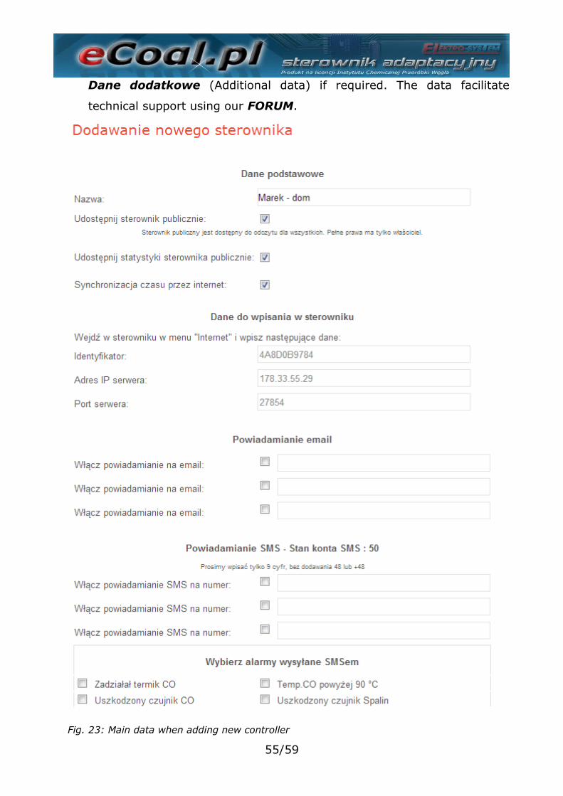
Dane dodatkowe (Additional data) if required. The data facilitate
technical support using our FORUM.
55/59
Fig. 23: Main data when adding new controller
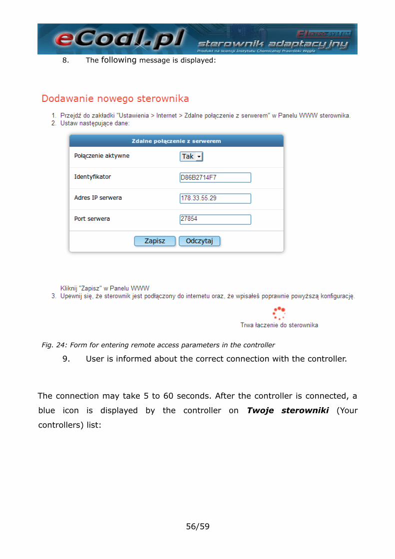
8. The following message is displayed:
9. User is informed about the correct connection with the controller.
The connection may take 5 to 60 seconds. After the controller is connected, a
blue icon is displayed by the controller on Twoje sterowniki (Your
controllers) list:
56/59
Fig. 24: Form for entering remote access parameters in the controller
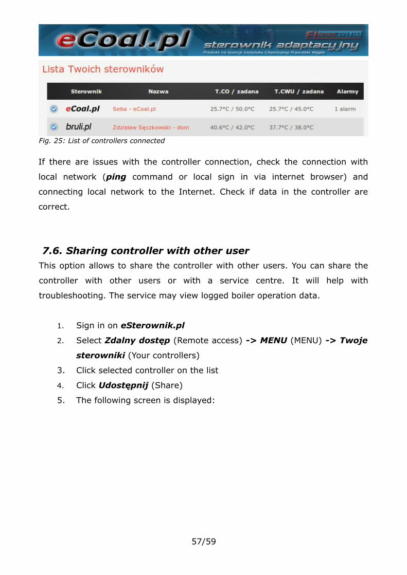
If there are issues with the controller connection, check the connection with
local network (ping command or local sign in via internet browser) and
connecting local network to the Internet. Check if data in the controller are
correct.
7.6. Sharing controller with other userThis option allows to share the controller with other users. You can share the
controller with other users or with a service centre. It will help with
troubleshooting. The service may view logged boiler operation data.
1. Sign in on eSterownik.pl
2. Select Zdalny dostęp (Remote access) -> MENU (MENU) -> Twoje
sterowniki (Your controllers)
3. Click selected controller on the list
4. Click Udostępnij (Share)
5. The following screen is displayed:
57/59
Fig. 25: List of controllers connected
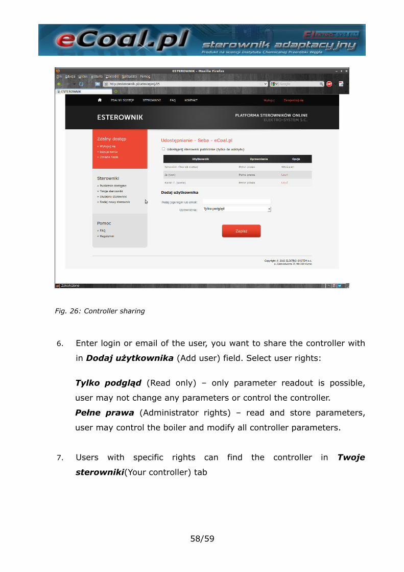
6. Enter login or email of the user, you want to share the controller with
in Dodaj użytkownika (Add user) field. Select user rights:
Tylko podgląd (Read only) – only parameter readout is possible,
user may not change any parameters or control the controller.
Pełne prawa (Administrator rights) – read and store parameters,
user may control the boiler and modify all controller parameters.
7. Users with specific rights can find the controller in Twoje
sterowniki(Your controller) tab
58/59
Fig. 26: Controller sharing
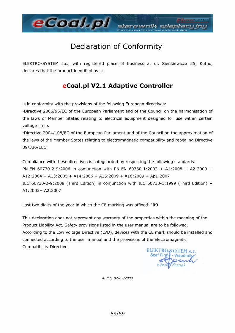
Declaration of Conformity
ELEKTRO-SYSTEM s.c., with registered place of business at ul. Sienkiewicza 25, Kutno,
declares that the product identified as: :
eCoal.pl V2.1 Adaptive Controller
is in conformity with the provisions of the following European directives:
•Directive 2006/95/EC of the European Parliament and of the Council on the harmonisation of
the laws of Member States relating to electrical equipment designed for use within certain
voltage limits
•Directive 2004/108/EC of the European Parliament and of the Council on the approximation of
the laws of the Member States relating to electromagnetic compatibility and repealing Directive
89/336/EEC
Compliance with these directives is safeguarded by respecting the following standards:
PN-EN 60730-2-9:2006 in conjunction with PN-EN 60730-1:2002 + A1:2008 + A2:2009 +
A12:2004 + A13:2005 + A14:2006 + A15:2009 + A16:2009 + Ap1:2007
IEC 60730-2-9:2008 (Third Edition) in conjunction with IEC 60730-1:1999 (Third Edition) +
A1:2003+ A2:2007
Last two digits of the year in which the CE marking was affixed: '09
This declaration does not represent any warranty of the properties within the meaning of the
Product Liability Act. Safety provisions listed in the user manual are to be followed.
According to the Low Voltage Directive (LVD), devices with the CE mark should be installed and
connected according to the user manual and the provisions of the Electromagnetic
Compatibility Directive.
Kutno, 07/07/2009
59/59


![diagram 5.1 [Converted] - Building Control NI · part of the flue serving an open-flued appliance. flue soot door debris collection space chimney appliance flue outlet appliance flue](https://img.pdfslide.us/doc/110x75/60ea4a68722f9641f22c1939/diagram-51-converted-building-control-ni-part-of-the-flue-serving-an-open-flued.jpg)