Embed Size (px)
Citation preview
User Manual
Wireless Pan & Tilt Camera
CIPCAMPTIWL
v1.0

CIPCAMPTIWL User Manual
2
Index
1 INTRODUCTION ................................................................................................................ 4
1.1 THE PACKAGE INCLUDES ................................................................................................. 4
1.2 FUNCTION AND FEATURES ............................................................................................... 4
1.3 TECHNICAL SPECIFICATIONS ............................................................................................ 4
2 APPEARANCE AND INTERFACE .................................................................................... 6
2.1 APPEARANCE .................................................................................................................. 6
2.2 INTERFACE ..................................................................................................................... 6
3 VISIT THE CAMERA FROM LAN ..................................................................................... 7
3.1 LAN CONNECTION ........................................................................................................... 7
3.2 SEARCH AND SET THE IP ADDRESS OF THE CAMERA .......................................................... 7
3.3 VISIT IP CAMERA ............................................................................................................ 8
3.3.1 Video Play Area ...................................................................................................... 8
4 VISIT IP CAMERA FROM WAN ...................................................................................... 10
4.1 WAN CONNECTION ........................................................................................................ 10
4.2 PORT FORWARDING ....................................................................................................... 11
4.3 DDNS ........................................................................................................................... 11
4.3.1 Free DDNS Portal .................................................................................................. 11
4.3.2 Third Party DDNS ................................................................................................. 12
5 OTHER SETTINGS.......................................................................................................... 12
5.1 NETWORK SETTING ....................................................................................................... 12
5.1.1 Basic Network Setting ........................................................................................... 12
5.1.2 WIFI Setting .......................................................................................................... 12
5.1.3 ADSL Setting ........................................................................................................ 13
5.1.4 UPnP Setting ........................................................................................................ 13
5.1.5 DDNS Setting ....................................................................................................... 14
5.1.6 MSN Setting .......................................................................................................... 14
5.2 ALARM SETTINGS .......................................................................................................... 14
5.2.1 Alarm Setting ........................................................................................................ 14
5.2.2 Mail Service Setting .............................................................................................. 16
5.2.3 FTP Service Setting .............................................................................................. 17
5.2.4 Alarm Server ......................................................................................................... 17
5.3 ADVANCED.................................................................................................................... 18
5.3.1 User Setting .......................................................................................................... 18
5.3.2 Multi Device Setting .............................................................................................. 18
5.3.3 Other settings ....................................................................................................... 19
5.4 MAINTAIN ...................................................................................................................... 20

CIPCAMPTIWL User Manual
3
5.4.1 Device Information ................................................................................................ 20
5.4.2 Time Setting .......................................................................................................... 20
5.4.3 Firmware upgrade ................................................................................................. 20
5.4.4 Restore Factory Default ........................................................................................ 20
5.4.5 User browsing Log ................................................................................................ 21
6 CENTRALIZATION CONTROL ....................................................................................... 21
7 FAQ .................................................................................................................................. 21
CIPCAMPTIWL User Manual
4
1 Introduction
The Wireless Pan & Tilt Camera combines a high quality digital video camera with
network connectivity and a powerful web server to bring clear video to your desktop from
anywhere on your local network or over the Internet.
1.1 The package includes
Conceptronic Wireless Pan & Tilt Camera
Product CD-ROM
Network cable
Power adapter
Replaceable antenna (1x)
Multi language quick guide
1.2 Function and Features
Built-in microphone enables users to monitor the sound on the site. Users can also
connect this equipment to a speaker, and it supports two-way intercom function.
Pan/tilt function with wide FOV of 270° horizontal and 120° vertical.
Easy and convenient to install.
Support 802.11b/g protocol, can build up wireless monitoring.
Infrared LED for night vision covers 5m area, suitable for 24 hours monitoring.
Motion detection and alarm pin can be connected to external sensors to detect
environmental situations.
Alarm record can be stored by email or FTP server.
Support mobile phone viewing.
Free DDNS.
Free software supporting Multi-view, Long time recording, video replay etc.
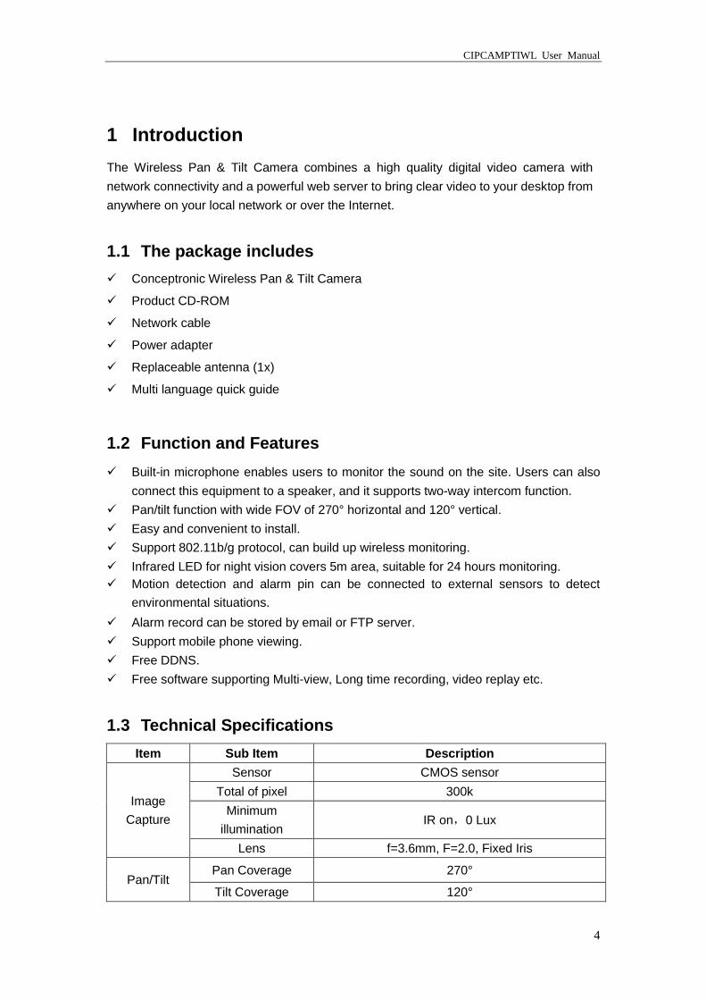
1.3 Technical Specifications
Item Sub Item Description
Image
Capture
Sensor CMOS sensor
Total of pixel 300k
Minimum
illumination IR on,0 Lux
Lens f=3.6mm, F=2.0, Fixed Iris
Pan/Tilt Pan Coverage 270°
Tilt Coverage 120°
CIPCAMPTIWL User Manual
5
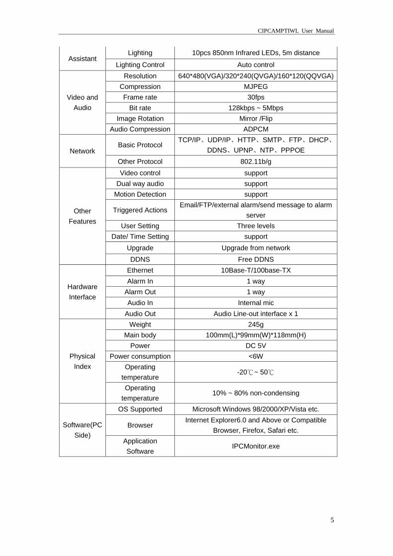
Assistant Lighting 10pcs 850nm Infrared LEDs, 5m distance
Lighting Control Auto control
Video and
Audio
Resolution 640*480(VGA)/320*240(QVGA)/160*120(QQVGA)
Compression MJPEG
Frame rate 30fps
Bit rate 128kbps ~ 5Mbps
Image Rotation Mirror /Flip
Audio Compression ADPCM
Network Basic Protocol
TCP/IP、UDP/IP、HTTP、SMTP、FTP、DHCP、
DDNS、UPNP、NTP、PPPOE
Other Protocol 802.11b/g
Other
Features
Video control support
Dual way audio support
Motion Detection support
Triggered Actions Email/FTP/external alarm/send message to alarm
server
User Setting Three levels
Date/ Time Setting support
Upgrade Upgrade from network
DDNS Free DDNS
Hardware
Interface
Ethernet 10Base-T/100base-TX
Alarm In 1 way
Alarm Out 1 way
Audio In Internal mic
Audio Out Audio Line-out interface x 1
Physical
Index
Weight 245g
Main body 100mm(L)*99mm(W)*118mm(H)
Power DC 5V
Power consumption <6W
Operating
temperature -20℃~ 50℃
Operating
temperature 10% ~ 80% non-condensing
Software(PC
Side)
OS Supported Microsoft Windows 98/2000/XP/Vista etc.
Browser Internet Explorer6.0 and Above or Compatible
Browser, Firefox, Safari etc.
Application
Software IPCMonitor.exe
CIPCAMPTIWL User Manual
6
2 Appearance and Interface
2.1 Appearance
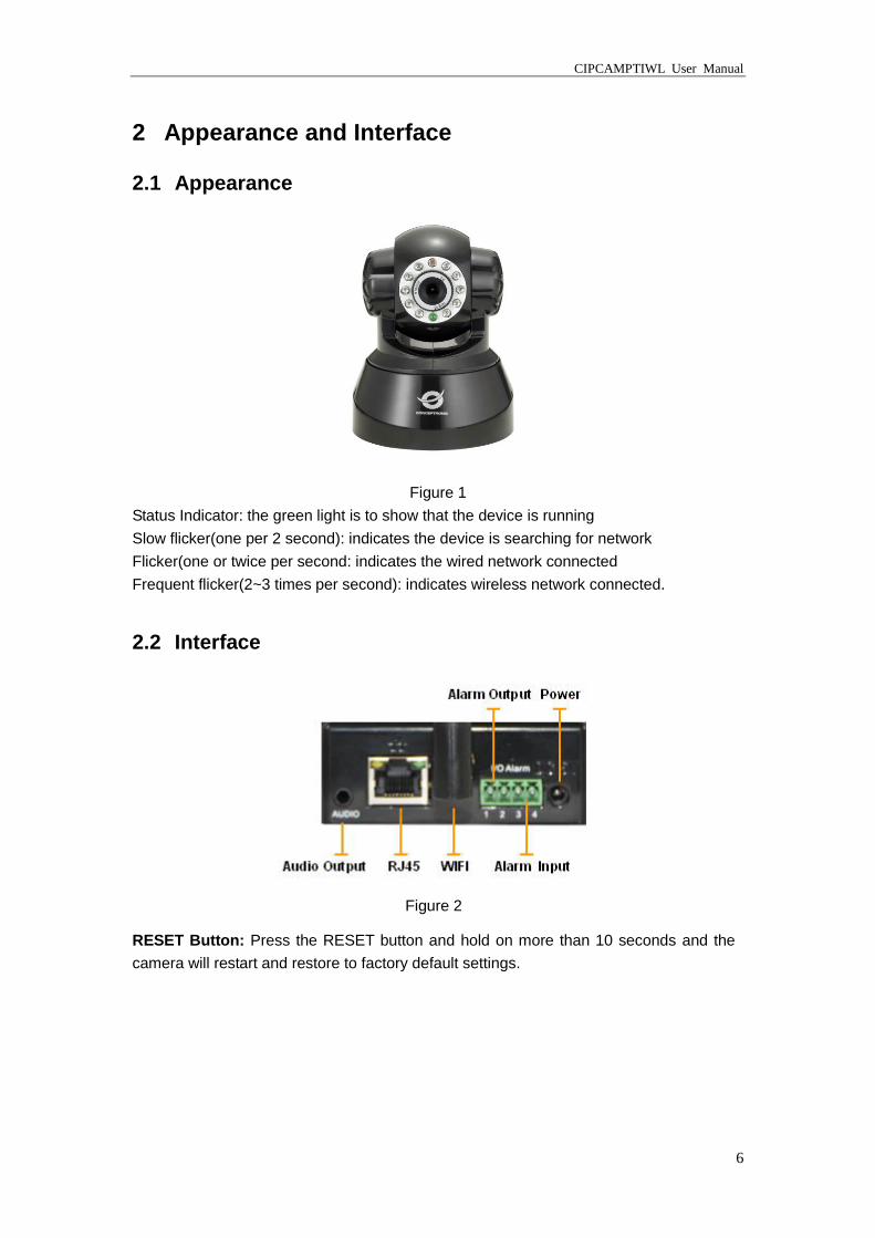
Figure 1
Status Indicator: the green light is to show that the device is running
Slow flicker(one per 2 second): indicates the device is searching for network
Flicker(one or twice per second: indicates the wired network connected
Frequent flicker(2~3 times per second): indicates wireless network connected.
2.2 Interface
Figure 2
RESET Button: Press the RESET button and hold on more than 10 seconds and the
camera will restart and restore to factory default settings.
CIPCAMPTIWL User Manual
7
3 Visit the Camera from LAN
3.1 LAN connection
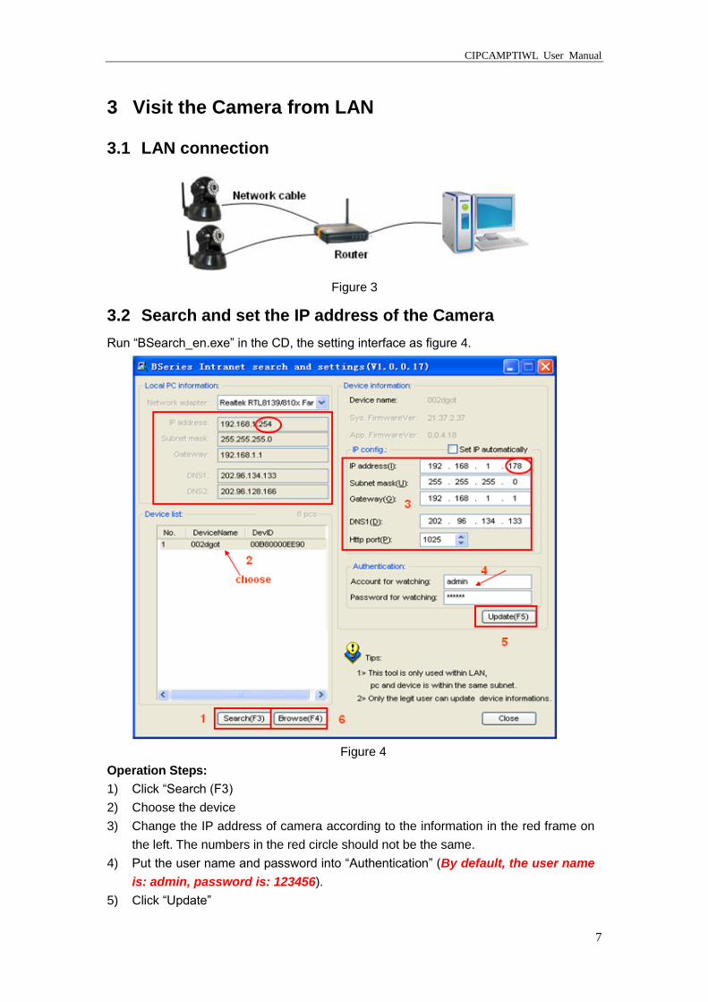
Figure 3
3.2 Search and set the IP address of the Camera
Run “BSearch_en.exe” in the CD, the setting interface as figure 4.
Figure 4
Operation Steps:
1) Click “Search (F3)
2) Choose the device
3) Change the IP address of camera according to the information in the red frame on
the left. The numbers in the red circle should not be the same.
4) Put the user name and password into “Authentication” (By default, the user name
is: admin, password is: 123456).
5) Click “Update”
CIPCAMPTIWL User Manual
8
6) After successfully updatong, click “Search (F3)”, choose the device and click
“Browse (F4)”. Then you may view the camera, like figure 5.
NOTE:
1) If you don’t know how to fill out the content of “IP config”, you could also tick the “Set
IP automatically” to get the IP address from the router automatically.
2) If you have the firewall software in your PC, when you run the BSearch_en.exe, it
may pop up a window to say “whether you want to block this program or not”, then
you should choose not to block.
3) The default IP address is 192.168.0.178 and default http port is 80.
Figure 5
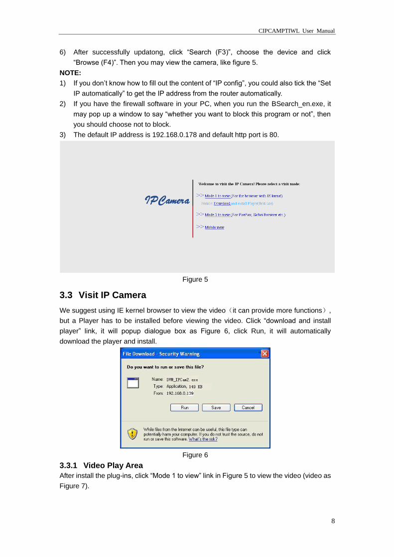
3.3 Visit IP Camera
We suggest using IE kernel browser to view the video(it can provide more functions),
but a Player has to be installed before viewing the video. Click “download and install
player” link, it will popup dialogue box as Figure 6, click Run, it will automatically
download the player and install.
Figure 6
3.3.1 Video Play Area
After install the plug-ins, click “Mode 1 to view” link in Figure 5 to view the video (video as
Figure 7).
CIPCAMPTIWL User Manual
9
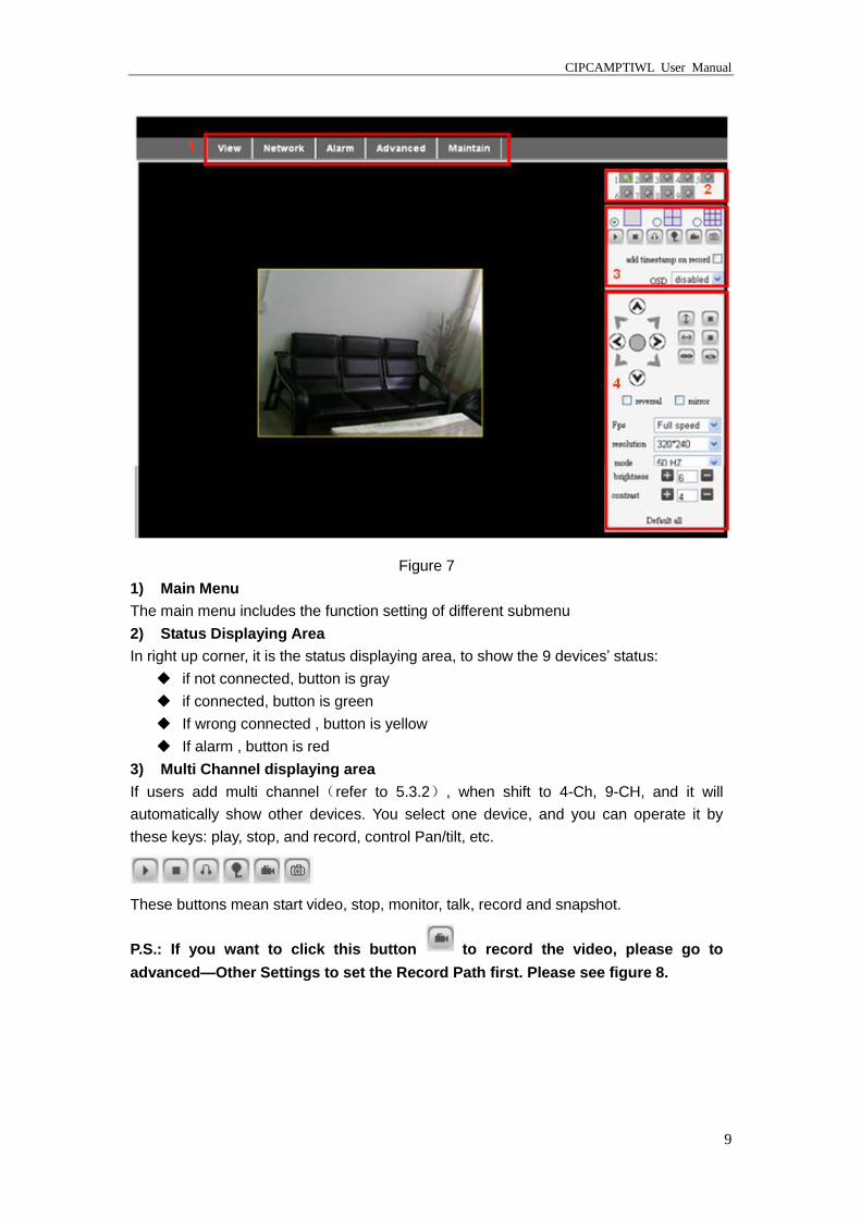
Figure 7
1) Main Menu
The main menu includes the function setting of different submenu
2) Status Displaying Area
In right up corner, it is the status displaying area, to show the 9 devices’ status:
if not connected, button is gray
if connected, button is green
If wrong connected , button is yellow
If alarm , button is red
3) Multi Channel displaying area
If users add multi channel(refer to 5.3.2), when shift to 4-Ch, 9-CH, and it will
automatically show other devices. You select one device, and you can operate it by
these keys: play, stop, and record, control Pan/tilt, etc.
These buttons mean start video, stop, monitor, talk, record and snapshot.
P.S.: If you want to click this button to record the video, please go to
advanced—Other Settings to set the Record Path first. Please see figure 8.
CIPCAMPTIWL User Manual
10
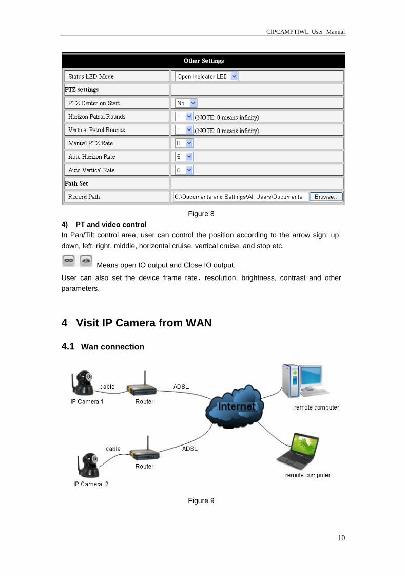
Figure 8
4) PT and video control
In Pan/Tilt control area, user can control the position according to the arrow sign: up,
down, left, right, middle, horizontal cruise, vertical cruise, and stop etc.
Means open IO output and Close IO output.
User can also set the device frame rate、resolution, brightness, contrast and other
parameters.
4 Visit IP Camera from WAN
4.1 Wan connection
Figure 9
CIPCAMPTIWL User Manual
11
4.2 Port forwarding
If visit IP Camera from WAN, you must do port forwarding on the router. Take Netgear
router for example.
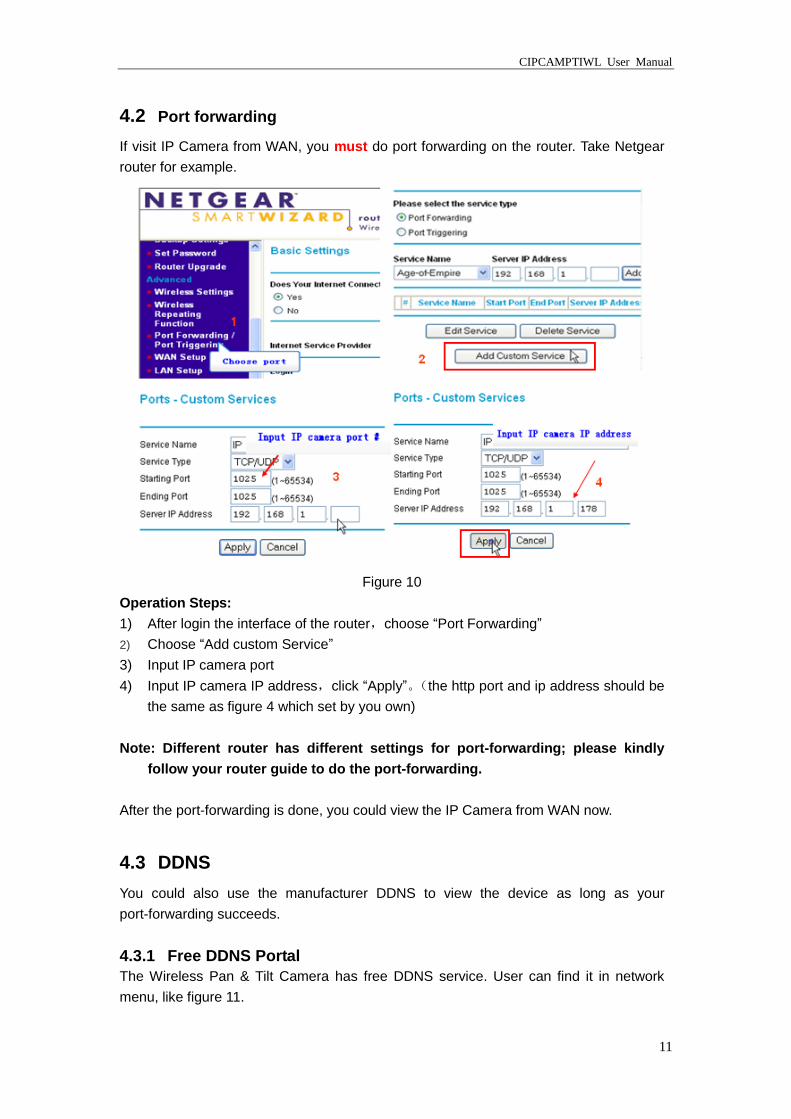
Figure 10
Operation Steps:
1) After login the interface of the router,choose “Port Forwarding”
2) Choose “Add custom Service”
3) Input IP camera port
4) Input IP camera IP address,click “Apply”。(the http port and ip address should be
the same as figure 4 which set by you own)
Note: Different router has different settings for port-forwarding; please kindly
follow your router guide to do the port-forwarding.
After the port-forwarding is done, you could view the IP Camera from WAN now.
4.3 DDNS
You could also use the manufacturer DDNS to view the device as long as your
port-forwarding succeeds.
4.3.1 Free DDNS Portal
The Wireless Pan & Tilt Camera has free DDNS service. User can find it in network
menu, like figure 11.
CIPCAMPTIWL User Manual
12
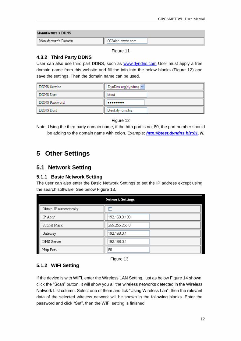
Figure 11
4.3.2 Third Party DDNS
User can also use third part DDNS, such as www.dyndns.com User must apply a free
domain name from this website and fill the info into the below blanks (Figure 12) and
save the settings. Then the domain name can be used.
Figure 12
Note: Using the third party domain name, if the http port is not 80, the port number should
be adding to the domain name with colon. Example: http://btest.dyndns.biz:81. N.
5 Other Settings
5.1 Network Setting
5.1.1 Basic Network Setting
The user can also enter the Basic Network Settings to set the IP address except using
the search software. See below Figure 13.
Figure 13
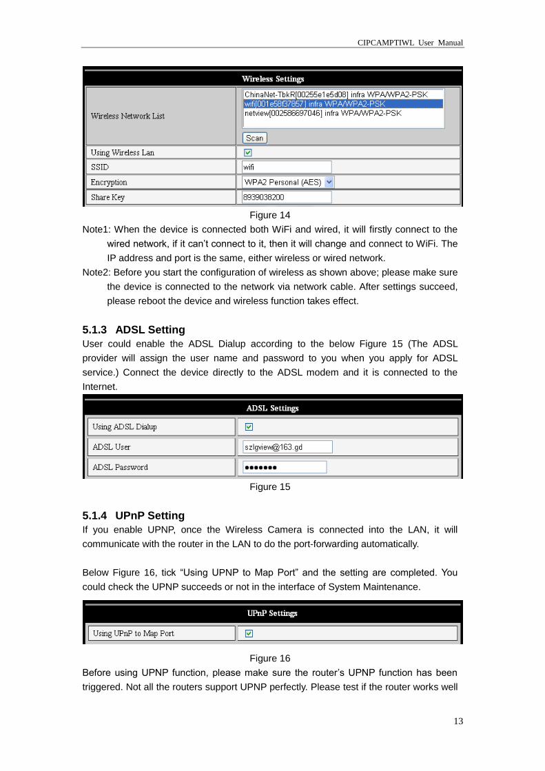
5.1.2 WIFI Setting
If the device is with WIFI, enter the Wireless LAN Setting, just as below Figure 14 shown,
click the “Scan” button, it will show you all the wireless networks detected in the Wireless
Network List column. Select one of them and tick “Using Wireless Lan”, then the relevant
data of the selected wireless network will be shown in the following blanks. Enter the
password and click “Set”, then the WIFI setting is finished.
CIPCAMPTIWL User Manual
13
Figure 14
Note1: When the device is connected both WiFi and wired, it will firstly connect to the
wired network, if it can’t connect to it, then it will change and connect to WiFi. The
IP address and port is the same, either wireless or wired network.
Note2: Before you start the configuration of wireless as shown above; please make sure
the device is connected to the network via network cable. After settings succeed,
please reboot the device and wireless function takes effect.
5.1.3 ADSL Setting
User could enable the ADSL Dialup according to the below Figure 15 (The ADSL
provider will assign the user name and password to you when you apply for ADSL
service.) Connect the device directly to the ADSL modem and it is connected to the
Internet.
Figure 15
5.1.4 UPnP Setting
If you enable UPNP, once the Wireless Camera is connected into the LAN, it will
communicate with the router in the LAN to do the port-forwarding automatically.
Below Figure 16, tick “Using UPNP to Map Port” and the setting are completed. You
could check the UPNP succeeds or not in the interface of System Maintenance.
Figure 16
Before using UPNP function, please make sure the router’s UPNP function has been
triggered. Not all the routers support UPNP perfectly. Please test if the router works well
CIPCAMPTIWL User Manual
14
with the equipment, if not, we would suggest you to disable this function and do the
port-forwarding manually.
5.1.5 DDNS Setting
Please refer to the content in 4.3.
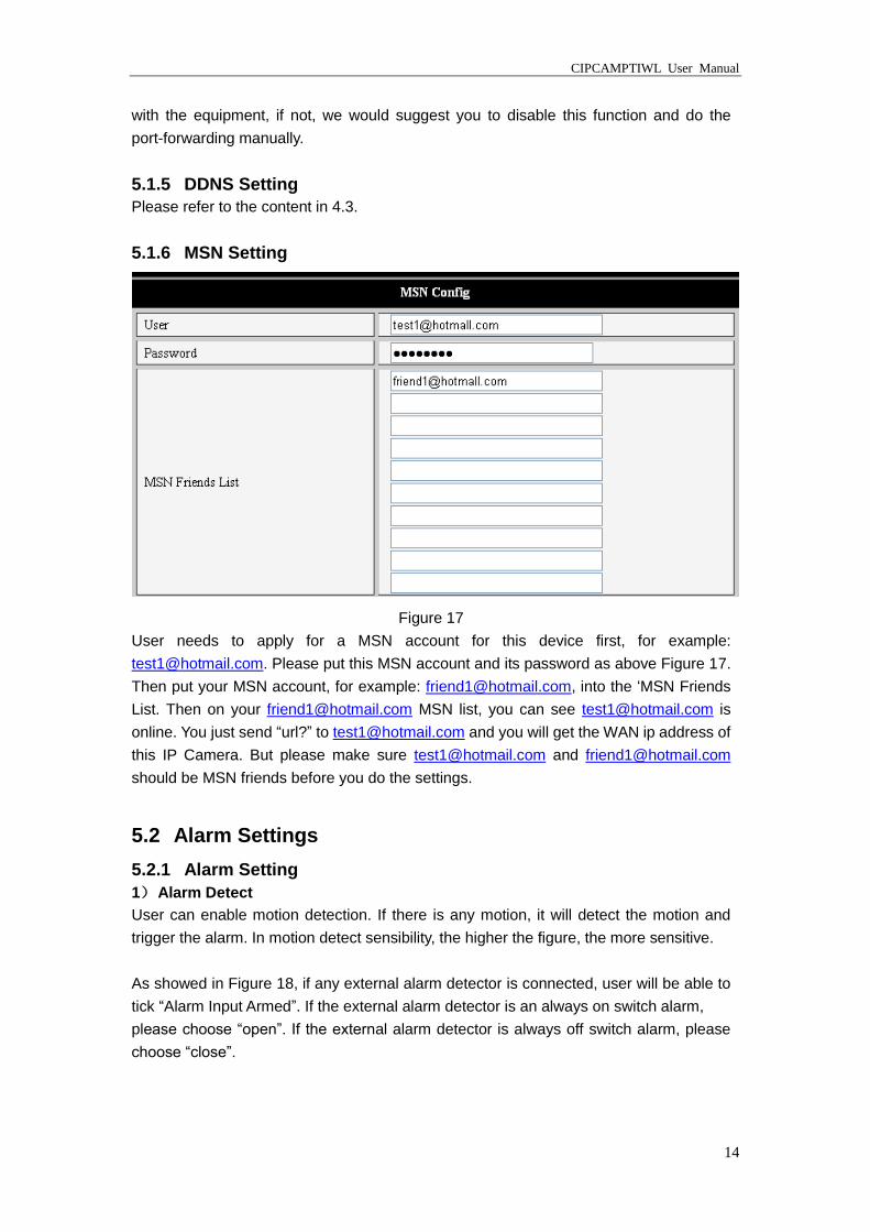
5.1.6 MSN Setting
Figure 17
User needs to apply for a MSN account for this device first, for example:
[email protected]. Please put this MSN account and its password as above Figure 17.
Then put your MSN account, for example: [email protected], into the ‘MSN Friends
List. Then on your [email protected] MSN list, you can see [email protected] is
online. You just send “url?” to [email protected] and you will get the WAN ip address of
this IP Camera. But please make sure [email protected] and [email protected]
should be MSN friends before you do the settings.
5.2 Alarm Settings
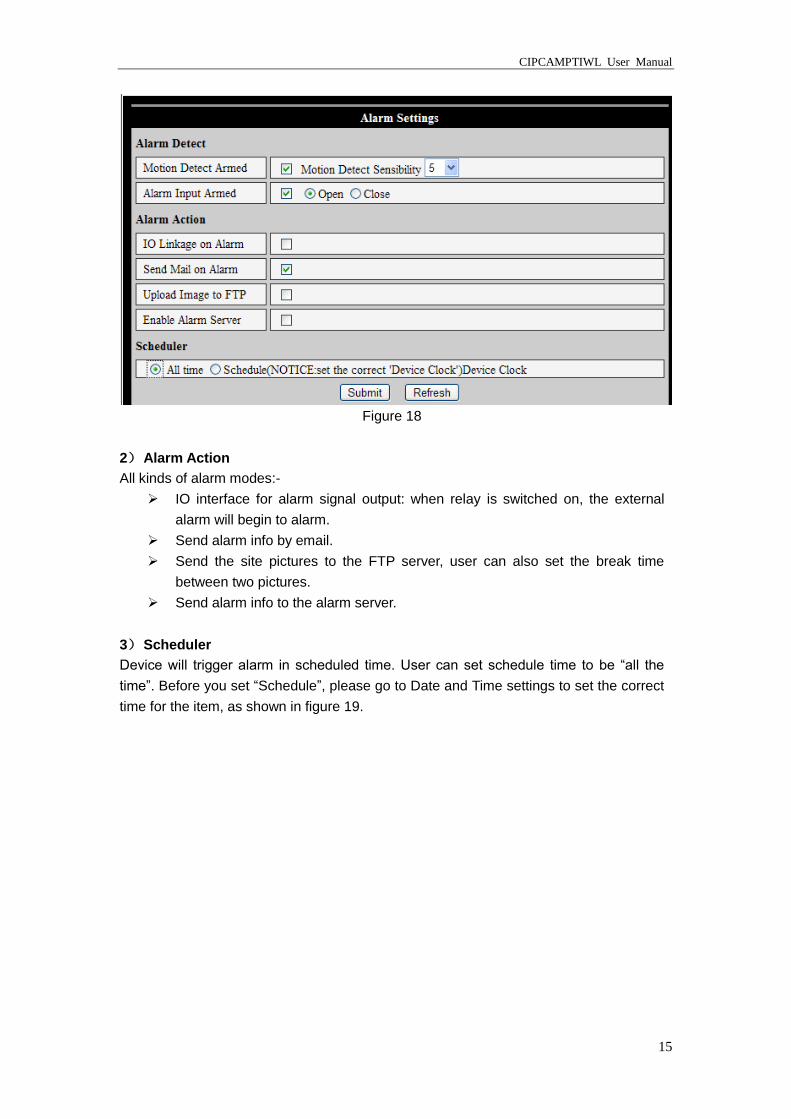
5.2.1 Alarm Setting
1) Alarm Detect
User can enable motion detection. If there is any motion, it will detect the motion and
trigger the alarm. In motion detect sensibility, the higher the figure, the more sensitive.
As showed in Figure 18, if any external alarm detector is connected, user will be able to
tick “Alarm Input Armed”. If the external alarm detector is an always on switch alarm,
please choose “open”. If the external alarm detector is always off switch alarm, please
choose “close”.
CIPCAMPTIWL User Manual
15
Figure 18
2) Alarm Action
All kinds of alarm modes:-
IO interface for alarm signal output: when relay is switched on, the external
alarm will begin to alarm.
Send alarm info by email.
Send the site pictures to the FTP server, user can also set the break time
between two pictures.
Send alarm info to the alarm server.
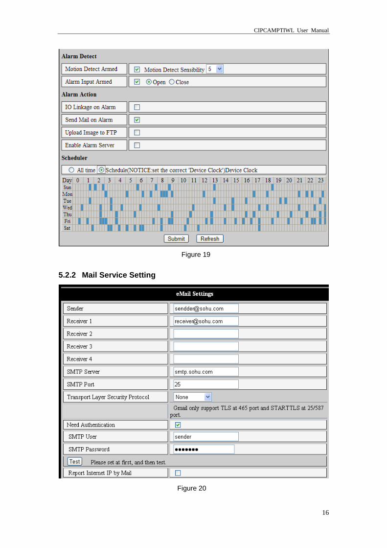
3) Scheduler
Device will trigger alarm in scheduled time. User can set schedule time to be “all the
time”. Before you set “Schedule”, please go to Date and Time settings to set the correct
time for the item, as shown in figure 19.
CIPCAMPTIWL User Manual
16
Figure 19
5.2.2 Mail Service Setting
Figure 20
CIPCAMPTIWL User Manual
17
The device will send alarm email to you. You only need to fill out the blanks with your
email address as shown in Figure 20. After the setting, please click save and test to
check if it works properly. If it is properly set, user can tick to enable “Report Internet IP
by mail”. After every restart, the device will send its Internet IP address to user’s email
address.
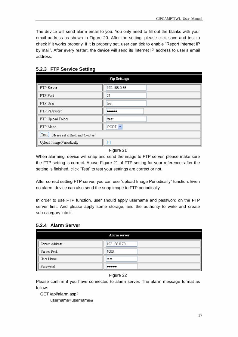
5.2.3 FTP Service Setting
Figure 21
When alarming, device will snap and send the image to FTP server, please make sure
the FTP setting is correct. Above Figure 21 of FTP setting for your reference, after the
setting is finished, click “Test” to test your settings are correct or not.
After correct setting FTP server, you can use “upload Image Periodically” function. Even
no alarm, device can also send the snap image to FTP periodically.
In order to use FTP function, user should apply username and password on the FTP
server first. And please apply some storage, and the authority to write and create
sub-category into it.
5.2.4 Alarm Server
Figure 22
Please confirm if you have connected to alarm server. The alarm message format as
follow:
GET /api/alarm.asp?
username=username&
CIPCAMPTIWL User Manual
18
userpwd=password&
rea=alarm type (1=Motion Detection, 2 =Alarm from Alarm in port)&
io=0
Alarm server needs developing by user. User can extend other functions on this server,
like SMS, MMS alarm, and mobile phone etc.
5.3 Advanced
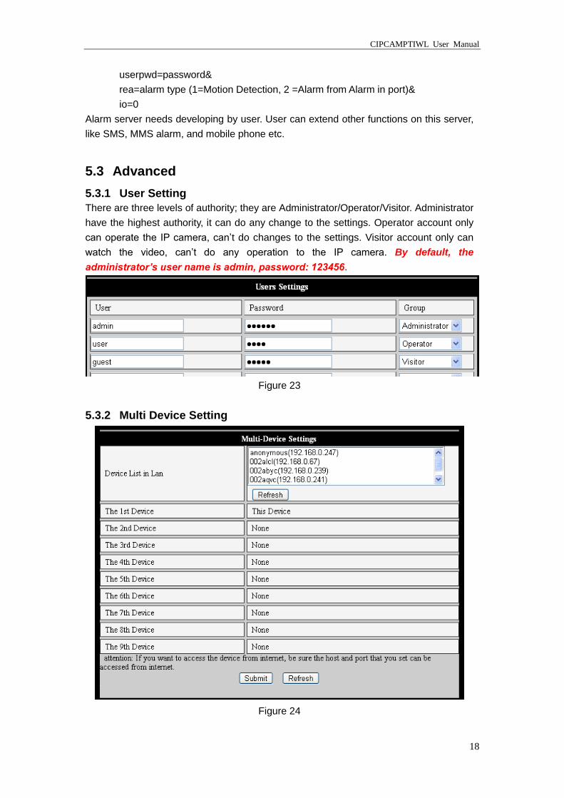
5.3.1 User Setting
There are three levels of authority; they are Administrator/Operator/Visitor. Administrator
have the highest authority, it can do any change to the settings. Operator account only
can operate the IP camera, can’t do changes to the settings. Visitor account only can
watch the video, can’t do any operation to the IP camera. By default, the
administrator’s user name is admin, password: 123456.
Figure 23
5.3.2 Multi Device Setting
Figure 24
CIPCAMPTIWL User Manual
19
As Figure 24, User can maximum add 9 devices to view the device simultaneously. Click
refresh button to check the device in the LAN. When click the device, will popup setting
dialogue box and input the device info, as figure 25 and click save. After that, must click
submit button to save.
Figure 25
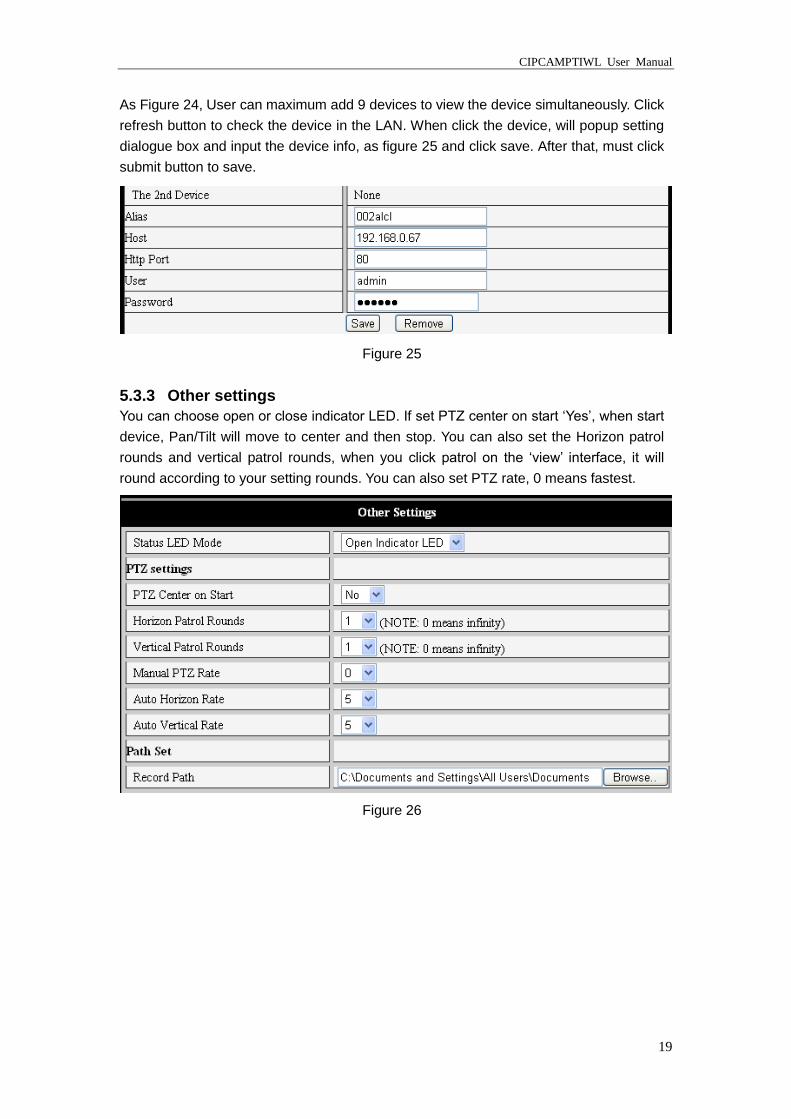
5.3.3 Other settings
You can choose open or close indicator LED. If set PTZ center on start ‘Yes’, when start
device, Pan/Tilt will move to center and then stop. You can also set the Horizon patrol
rounds and vertical patrol rounds, when you click patrol on the ‘view’ interface, it will
round according to your setting rounds. You can also set PTZ rate, 0 means fastest.
Figure 26
CIPCAMPTIWL User Manual
20
5.4 Maintain
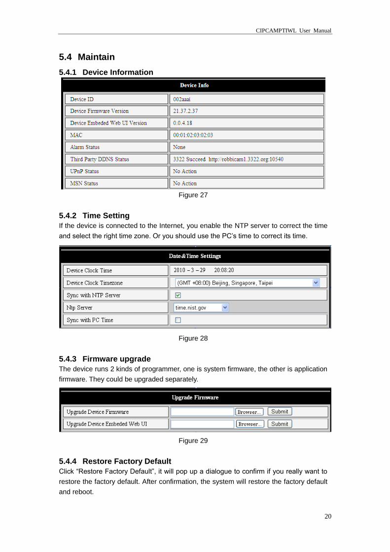
5.4.1 Device Information
Figure 27
5.4.2 Time Setting
If the device is connected to the Internet, you enable the NTP server to correct the time
and select the right time zone. Or you should use the PC’s time to correct its time.
Figure 28
5.4.3 Firmware upgrade
The device runs 2 kinds of programmer, one is system firmware, the other is application
firmware. They could be upgraded separately.
Figure 29
5.4.4 Restore Factory Default
Click “Restore Factory Default”, it will pop up a dialogue to confirm if you really want to
restore the factory default. After confirmation, the system will restore the factory default
and reboot.
CIPCAMPTIWL User Manual
21
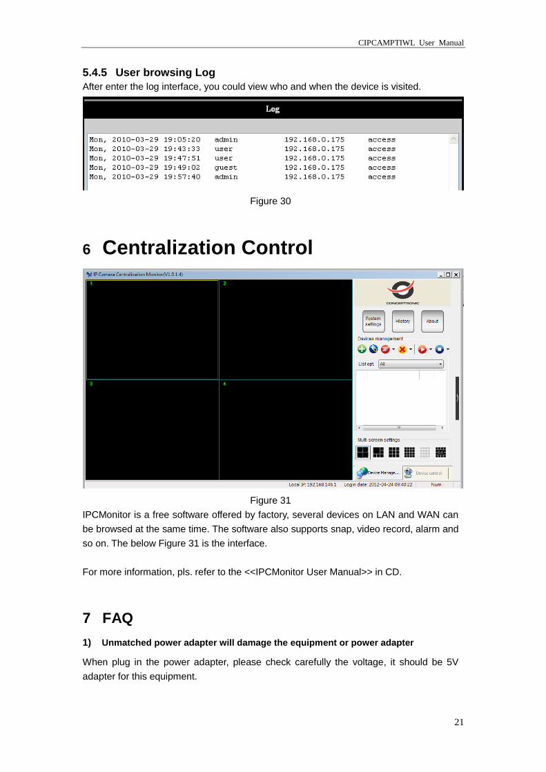
5.4.5 User browsing Log
After enter the log interface, you could view who and when the device is visited.
Figure 30
6 Centralization Control
Figure 31
IPCMonitor is a free software offered by factory, several devices on LAN and WAN can
be browsed at the same time. The software also supports snap, video record, alarm and
so on. The below Figure 31 is the interface.
For more information, pls. refer to the <<IPCMonitor User Manual>> in CD.
7 FAQ
1) Unmatched power adapter will damage the equipment or power adapter
When plug in the power adapter, please check carefully the voltage, it should be 5V
adapter for this equipment.
CIPCAMPTIWL User Manual
22
2) Slow browser speed
This equipment adopts MJEPG compression format, it needs large network bandwidth,
the narrow bandwidth will affect the browse speed. The typical bandwidth uses situation
as below:
640x480@10fps : 4.0 Megabits ~ 5.0 Megabits
320x240@30fps : 1.2 Megabits ~ 1.6 Megabits
3) Color difference
The default is infrared lens, when visit outdoor or strong infrared light scenes, there are
color differences, the color is not accordance to the real scenes. User can change it to
color lens to solve this problem, but color lens can only use under the daylight situation.
4) Can’t find equipment via search software after connect to LAN
Make sure the equipment and PC is in the same LAN; if install firewall software, please
close it and try again.
5) Can find equipment via search software, but can’t visit
If the IP address of IP camera and PC is not in the same Network Segment, you should
change them on the same Network Segment before visit. Network Segment is the first
three number of IP address. If the IP address of PC is 192.168.0.100, so it can only visit
the equipment which IP address is between 192.168.0.1~192.168.0.255.
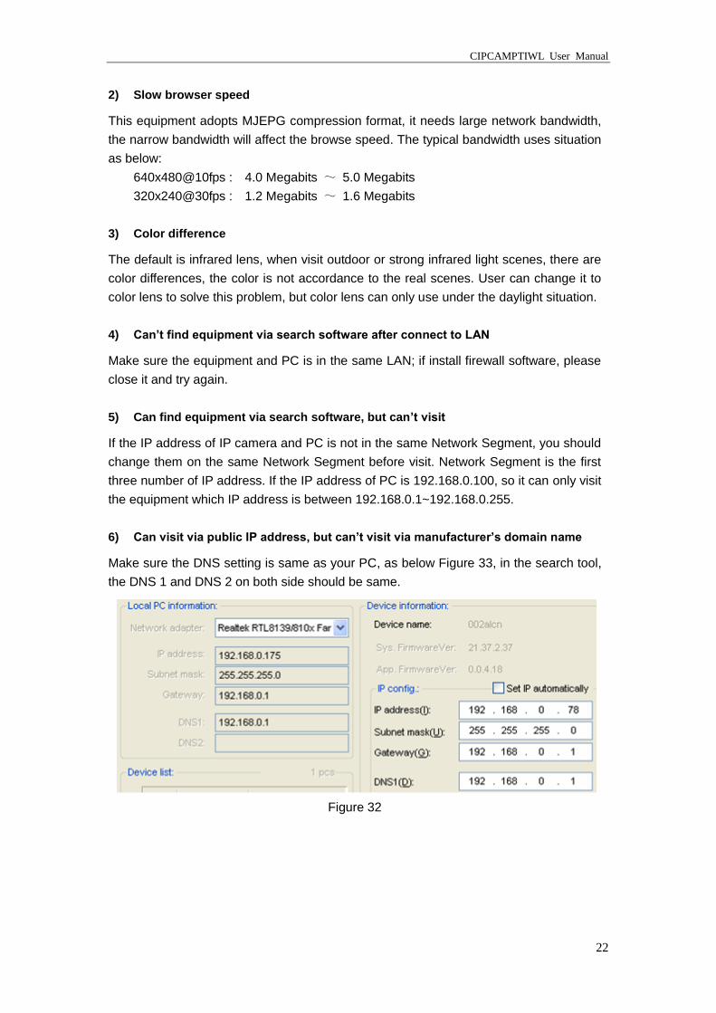
6) Can visit via public IP address, but can’t visit via manufacturer’s domain name
Make sure the DNS setting is same as your PC, as below Figure 33, in the search tool,
the DNS 1 and DNS 2 on both side should be same.
Figure 32