Embed Size (px)
Citation preview
User Manual
1. Introduction VanSimFM (VANET Simulation Framework Modeller) is an extensible open
source application that generates simulation experiments for VANET applications. It also allows its execution and the execution of AWK scripts to process the resulting simulation data.
This manual intends to offer VanSimFM users a reference to install and execute the application.
2. Requirements and installation VanSimFM has been tested on a Linux environment; a Linux environment is
recommended in order to obtain better results. In order to execute the application the user has to unzip the compressed file with the application into a folder of his/her choice. It is very important not to rename or move any of the folders and files included in the compressed file.
VanSimFM doesn’t require further installation but in order to work it needs the following applications along with their dependencies installed in the system:
NS-2 version 2.35-RC6
NAM version 1.15-RC4
SUMO version 0.12.3
Java version 1.6.0_24
Python version 2.7
VanSimFM may work with other versions of the applications but the developers recommend those versions.
The Linux environment in which VanSimFM has been tested was executed in a virtual machine. This virtual machine had the following characteristics, which may vary depending on the virtualization program used and the characteristics of the host system:
Virtualization application: Sun VirtualBox version 4.0.8 r71778
Assigned memory: 1.024 MB
Video memory: 12 MB
Hard disk size: 8 GB
OS: Ubuntu version 10.10
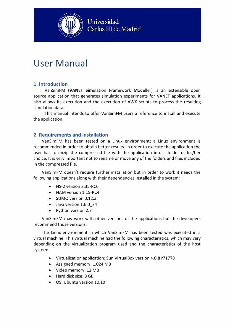
3. Execution In order to start VanSimFM user must double click on the file VanSimFM.jar.
Figure 1 shows VanSimFM initial screen. At this screen users are able to choose the action that will be executed and also change the folder where the simulations and their results will be stored along with other files generated by the application.
Figure 1 – VanSimFM main screen
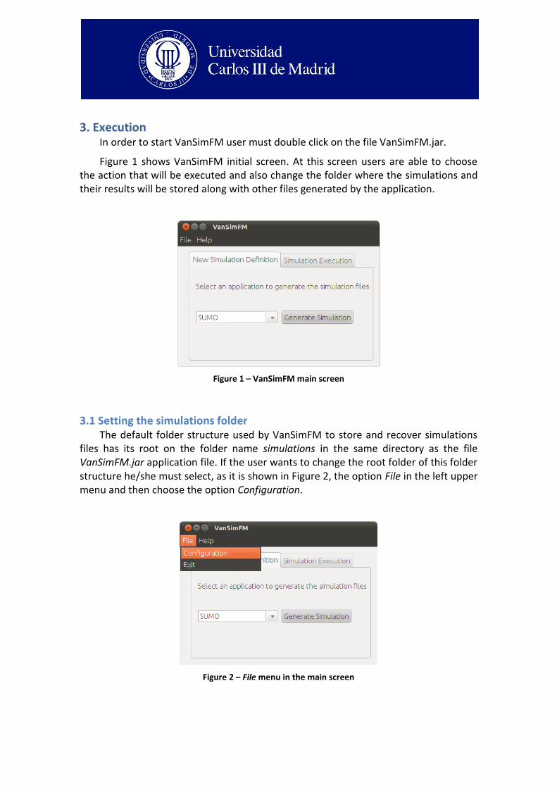
3.1 Setting the simulations folder The default folder structure used by VanSimFM to store and recover simulations
files has its root on the folder name simulations in the same directory as the file VanSimFM.jar application file. If the user wants to change the root folder of this folder structure he/she must select, as it is shown in Figure 2, the option File in the left upper menu and then choose the option Configuration.
Figure 2 – File menu in the main screen
Once the user click on Configuration the application will show the window shown on Figure 3. In this window users can change the name of the root folder of the folder structure that will contain the simulations used and generated by VanSimFM. Once the new name is defined users must click on the button Save configuration in order to make the change. At any moment users may click on the Cancel button to cancel this operation.
Figure 3 – Root folder name change screen
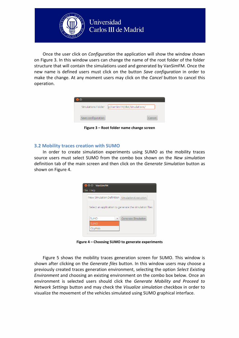
3.2 Mobility traces creation with SUMO In order to create simulation experiments using SUMO as the mobility traces
source users must select SUMO from the combo box shown on the New simulation definition tab of the main screen and then click on the Generate Simulation button as shown on Figure 4.
Figure 4 – Choosing SUMO to generate experiments
Figure 5 shows the mobility traces generation screen for SUMO. This window is shown after clicking on the Generate files button. In this window users may choose a previously created traces generation environment, selecting the option Select Existing Environment and choosing an existing environment on the combo box below. Once an environment is selected users should click the Generate Mobility and Proceed to Network Settings button and may check the Visualize simulation checkbox in order to visualize the movement of the vehicles simulated using SUMO graphical interface.
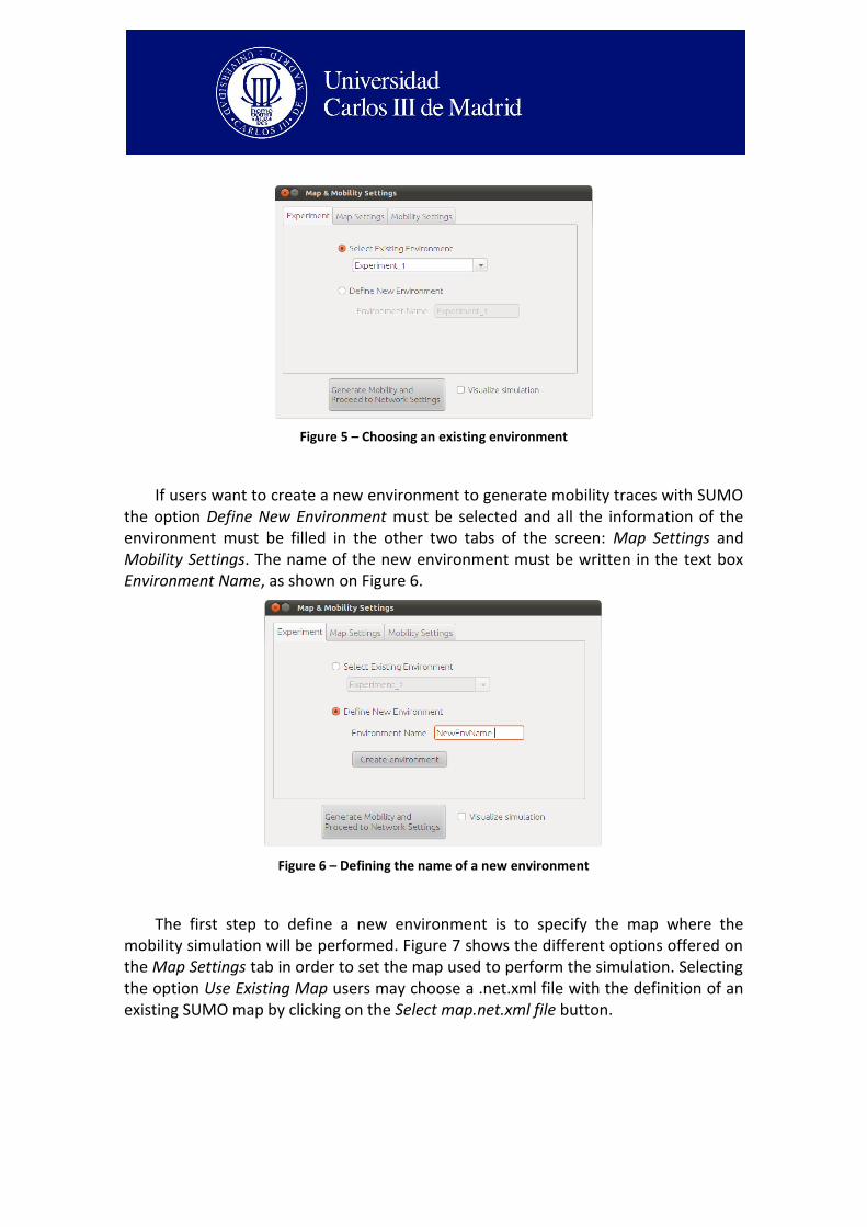
Figure 5 – Choosing an existing environment
If users want to create a new environment to generate mobility traces with SUMO the option Define New Environment must be selected and all the information of the environment must be filled in the other two tabs of the screen: Map Settings and Mobility Settings. The name of the new environment must be written in the text box Environment Name, as shown on Figure 6.
Figure 6 – Defining the name of a new environment
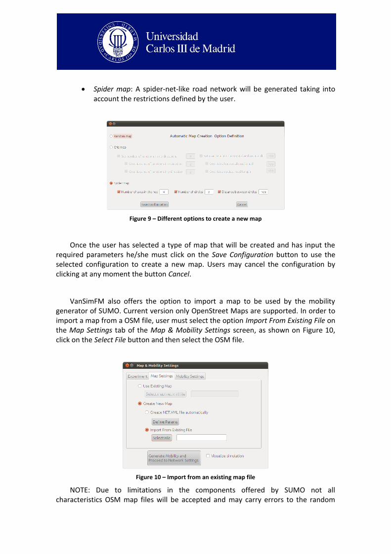
The first step to define a new environment is to specify the map where the mobility simulation will be performed. Figure 7 shows the different options offered on the Map Settings tab in order to set the map used to perform the simulation. Selecting the option Use Existing Map users may choose a .net.xml file with the definition of an existing SUMO map by clicking on the Select map.net.xml file button.
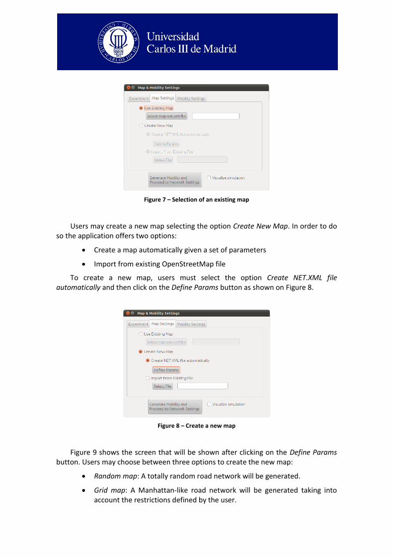
Figure 7 – Selection of an existing map
Users may create a new map selecting the option Create New Map. In order to do so the application offers two options:
Create a map automatically given a set of parameters
Import from existing OpenStreetMap file
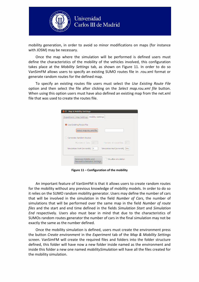
To create a new map, users must select the option Create NET.XML file automatically and then click on the Define Params button as shown on Figure 8.
Figure 8 – Create a new map
Figure 9 shows the screen that will be shown after clicking on the Define Params button. Users may choose between three options to create the new map:
Random map: A totally random road network will be generated.
Grid map: A Manhattan-like road network will be generated taking into account the restrictions defined by the user.
Spider map: A spider-net-like road network will be generated taking into account the restrictions defined by the user.
Figure 9 – Different options to create a new map
Once the user has selected a type of map that will be created and has input the required parameters he/she must click on the Save Configuration button to use the selected configuration to create a new map. Users may cancel the configuration by clicking at any moment the button Cancel.
VanSimFM also offers the option to import a map to be used by the mobility generator of SUMO. Current version only OpenStreet Maps are supported. In order to import a map from a OSM file, user must select the option Import From Existing File on the Map Settings tab of the Map & Mobility Settings screen, as shown on Figure 10, click on the Select File button and then select the OSM file.
Figure 10 – Import from an existing map file
NOTE: Due to limitations in the components offered by SUMO not all characteristics OSM map files will be accepted and may carry errors to the random
mobility generation, in order to avoid so minor modifications on maps (for instance with JOSM) may be necessary.
Once the map where the simulation will be performed is defined users must define the characteristics of the mobility of the vehicles involved, this configuration takes place at the Mobility Settings tab, as shown on Figure 11. In order to do so VanSimFM allows users to specify an existing SUMO routes file in .rou.xml format or generate random routes for the defined map.
To specify an existing routes file users must select the Use Existing Route File option and then select the file after clicking on the Select map.rou.xml file button. When using this option users must have also defined an existing map from the net.xml file that was used to create the routes file.
Figure 11 – Configuration of the mobility
An important feature of VanSimFM is that it allows users to create random routes for the mobility without any previous knowledge of mobility models. In order to do so it relies on the SUMO random mobility generator. Users may define the number of cars that will be involved in the simulation in the field Number of Cars, the number of simulations that will be performed over the same map in the field Number of route files and the start and end time defined in the fields Simulation Start and Simulation End respectively. Users also must bear in mind that due to the characteristics of SUMOs random routes generator the number of cars in the final simulation may not be exactly the same as the number defined.
Once the mobility simulation is defined, users must create the environment press the button Create environment in the Experiment tab of the Map & Mobility Settings screen. VanSimFM will create the required files and folders into the folder structure defined, this folder will have now a new folder inside named as the environment and inside this folder a new one named mobilitySimulation will have all the files created for the mobility simulation.
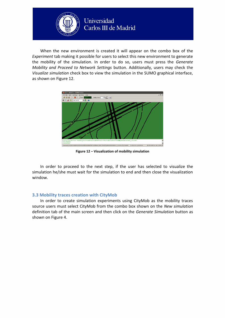
When the new environment is created it will appear on the combo box of the Experiment tab making it possible for users to select this new environment to generate the mobility of the simulation. In order to do so, users must press the Generate Mobility and Proceed to Network Settings button. Additionally, users may check the Visualize simulation check box to view the simulation in the SUMO graphical interface, as shown on Figure 12.
Figure 12 – Visualization of mobility simulation
In order to proceed to the next step, if the user has selected to visualize the simulation he/she must wait for the simulation to end and then close the visualization window.
3.3 Mobility traces creation with CityMob In order to create simulation experiments using CityMob as the mobility traces
source users must select CityMob from the combo box shown on the New simulation definition tab of the main screen and then click on the Generate Simulation button as shown on Figure 4.
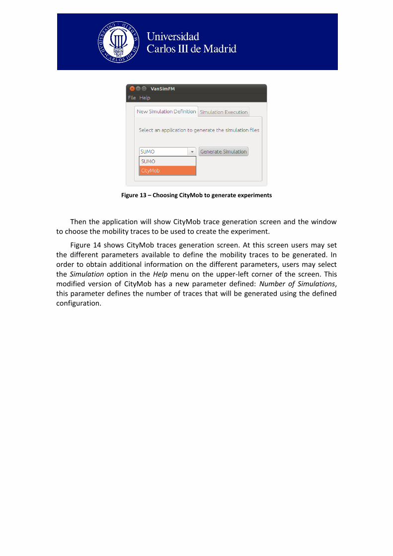
Figure 13 – Choosing CityMob to generate experiments
Then the application will show CityMob trace generation screen and the window to choose the mobility traces to be used to create the experiment.
Figure 14 shows CityMob traces generation screen. At this screen users may set the different parameters available to define the mobility traces to be generated. In order to obtain additional information on the different parameters, users may select the Simulation option in the Help menu on the upper-left corner of the screen. This modified version of CityMob has a new parameter defined: Number of Simulations, this parameter defines the number of traces that will be generated using the defined configuration.
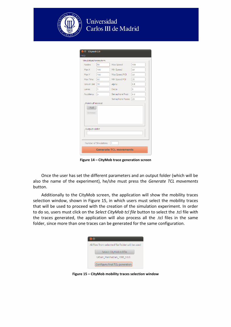
Figure 14 – CityMob trace generation screen
Once the user has set the different parameters and an output folder (which will be also the name of the experiment), he/she must press the Generate TCL movements button.
Additionally to the CityMob screen, the application will show the mobility traces selection window, shown in Figure 15, in which users must select the mobility traces that will be used to proceed with the creation of the simulation experiment. In order to do so, users must click on the Select CityMob tcl file button to select the .tcl file with the traces generated, the application will also process all the .tcl files in the same folder, since more than one traces can be generated for the same configuration.
Figure 15 – CityMob mobility traces selection window
Once the user has selected the tcl files to be used by the application he/she must press the Configure final TCL generation to proceed to the next stage of the experiment generation: the network simulation configuration.
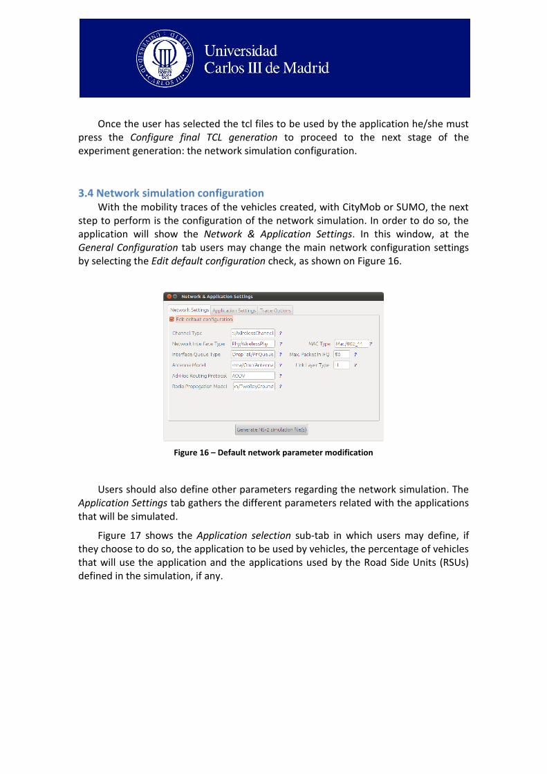
3.4 Network simulation configuration With the mobility traces of the vehicles created, with CityMob or SUMO, the next
step to perform is the configuration of the network simulation. In order to do so, the application will show the Network & Application Settings. In this window, at the General Configuration tab users may change the main network configuration settings by selecting the Edit default configuration check, as shown on Figure 16.
Figure 16 – Default network parameter modification
Users should also define other parameters regarding the network simulation. The Application Settings tab gathers the different parameters related with the applications that will be simulated.
Figure 17 shows the Application selection sub-tab in which users may define, if they choose to do so, the application to be used by vehicles, the percentage of vehicles that will use the application and the applications used by the Road Side Units (RSUs) defined in the simulation, if any.
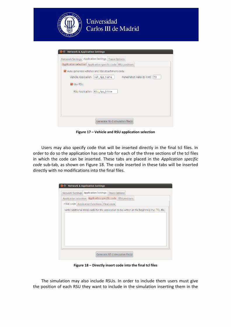
Figure 17 – Vehicle and RSU application selection
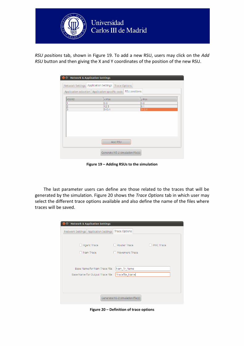
Users may also specify code that will be inserted directly in the final tcl files. In order to do so the application has one tab for each of the three sections of the tcl files in which the code can be inserted. These tabs are placed in the Application specific code sub-tab, as shown on Figure 18. The code inserted in these tabs will be inserted directly with no modifications into the final files.
Figure 18 – Directly insert code into the final tcl files
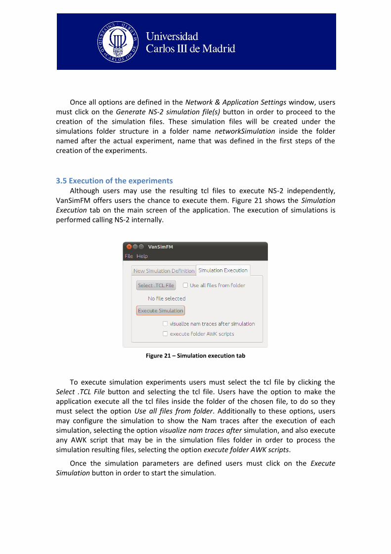
The simulation may also include RSUs. In order to include them users must give the position of each RSU they want to include in the simulation inserting them in the
RSU positions tab, shown in Figure 19. To add a new RSU, users may click on the Add RSU button and then giving the X and Y coordinates of the position of the new RSU.
Figure 19 – Adding RSUs to the simulation
The last parameter users can define are those related to the traces that will be generated by the simulation. Figure 20 shows the Trace Options tab in which user may select the different trace options available and also define the name of the files where traces will be saved.
Figure 20 – Definition of trace options
Once all options are defined in the Network & Application Settings window, users must click on the Generate NS-2 simulation file(s) button in order to proceed to the creation of the simulation files. These simulation files will be created under the simulations folder structure in a folder name networkSimulation inside the folder named after the actual experiment, name that was defined in the first steps of the creation of the experiments.
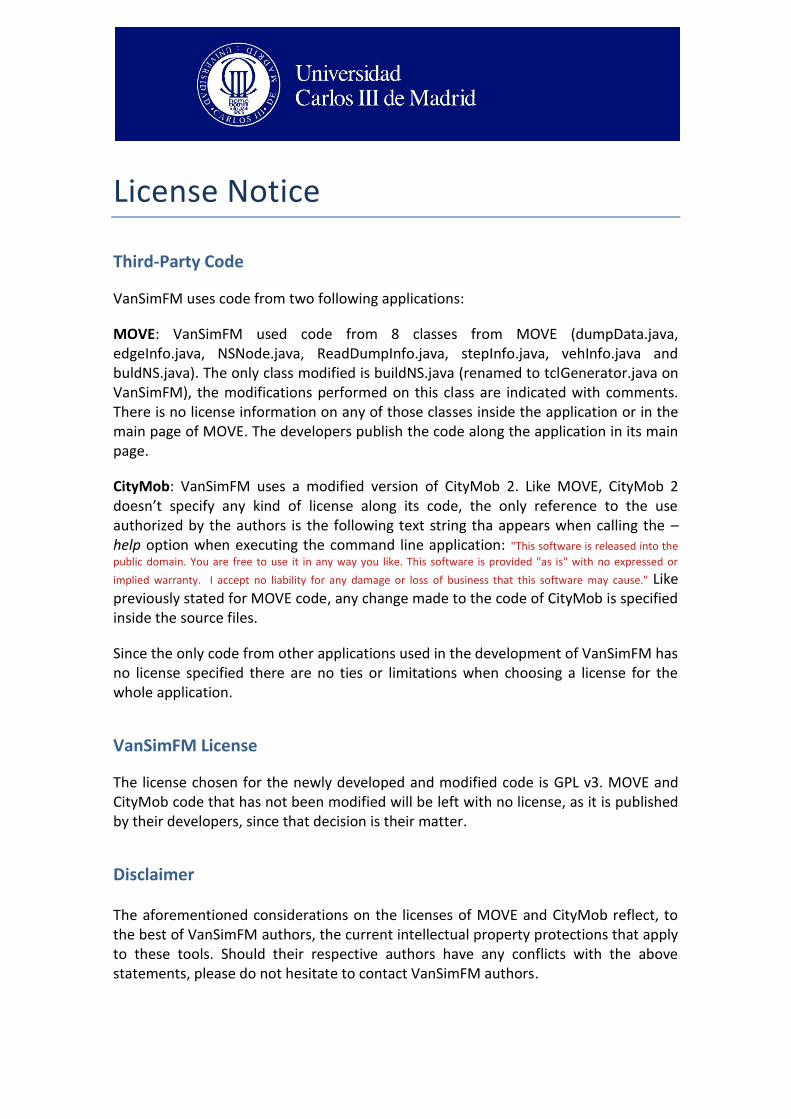
3.5 Execution of the experiments Although users may use the resulting tcl files to execute NS-2 independently,
VanSimFM offers users the chance to execute them. Figure 21 shows the Simulation Execution tab on the main screen of the application. The execution of simulations is performed calling NS-2 internally.
Figure 21 – Simulation execution tab
To execute simulation experiments users must select the tcl file by clicking the Select .TCL File button and selecting the tcl file. Users have the option to make the application execute all the tcl files inside the folder of the chosen file, to do so they must select the option Use all files from folder. Additionally to these options, users may configure the simulation to show the Nam traces after the execution of each simulation, selecting the option visualize nam traces after simulation, and also execute any AWK script that may be in the simulation files folder in order to process the simulation resulting files, selecting the option execute folder AWK scripts.
Once the simulation parameters are defined users must click on the Execute Simulation button in order to start the simulation.
License Notice
Third-Party Code
VanSimFM uses code from two following applications:
MOVE: VanSimFM used code from 8 classes from MOVE (dumpData.java, edgeInfo.java, NSNode.java, ReadDumpInfo.java, stepInfo.java, vehInfo.java and buldNS.java). The only class modified is buildNS.java (renamed to tclGenerator.java on VanSimFM), the modifications performed on this class are indicated with comments. There is no license information on any of those classes inside the application or in the main page of MOVE. The developers publish the code along the application in its main page.
CityMob: VanSimFM uses a modified version of CityMob 2. Like MOVE, CityMob 2 doesn’t specify any kind of license along its code, the only reference to the use authorized by the authors is the following text string tha appears when calling the –help option when executing the command line application: "This software is released into the
public domain. You are free to use it in any way you like. This software is provided "as is" with no expressed or
implied warranty. I accept no liability for any damage or loss of business that this software may cause." Like previously stated for MOVE code, any change made to the code of CityMob is specified inside the source files.
Since the only code from other applications used in the development of VanSimFM has no license specified there are no ties or limitations when choosing a license for the whole application.
VanSimFM License
The license chosen for the newly developed and modified code is GPL v3. MOVE and CityMob code that has not been modified will be left with no license, as it is published by their developers, since that decision is their matter.
Disclaimer The aforementioned considerations on the licenses of MOVE and CityMob reflect, to the best of VanSimFM authors, the current intellectual property protections that apply to these tools. Should their respective authors have any conflicts with the above statements, please do not hesitate to contact VanSimFM authors.