Embed Size (px)
Citation preview
1 EXPRESSION User Manual © 2003 ACES Laboratory
User Manual Version 1.0 05/28/2003
Authors: Par tha Biswas, Sudeep Pasricha, Prabhat Mishra, Aviral
Shr ivastava, Nikil Dutt and Alex Nicolau {partha, sudeep, pmishra, aviral, dutt, nicolau}@cecs.uci.edu
http://www.cecs.uci.edu/~aces
ACES Laboratory Center for Embedded Computer Systems
School of Information and Computer Science University of California, I rvine

2 EXPRESSION User Manual © 2003 ACES Laboratory
3 EXPRESSION User Manual © 2003 ACES Laboratory
TABLE OF CONTENTS
1. INTRODUCTION…………………………………………………………….……..5
2. EXPRESSION TOOLKIT SETUP…………………………………………..….………9
3. COMMAND LINE OPTIONS……………………………………………….….…… 17
4. ARCHITECTURE ENTRY……………………………………………….…..............19
5. DESIGN SPACE EXPLORATION………...……...……………………….…………. .44
6. BENCHMARKS..………………………………………….……………………… .72
7. OPEN ISSUES AND FUTURE DIRECTIONS.……………………………..….………...73
8. REFERENCES.……………………………………………….….………………....74
APPENDIX A: EXPRESSION ADL….………................................................................75
APPENDIX B: GENERIC MACHINE MODEL….……….................................................78

4 EXPRESSION User Manual © 2003 ACES Laboratory
Acknowledgements
We would like to thank and acknowledge the contributions of several former and current members of the ACES Lab in CECS, who helped make the EXPRESSION project a reality. EXPRESSION would not have been possible without the invaluable contributions of the following people: Ashok Halambi, Peter Grun, Asheesh Khare, Nick Savoiu, Radu Cornea, Srikanth Srinivasan and Vijay Ganesh. We are also grateful to all the members of the ACES Lab who took time out of their busy schedules to test and give feedback on the release, which helped us immensely.
5 EXPRESSION User Manual © 2003 ACES Laboratory
1. Introduction EXPRESSION is an Architecture Description Language (ADL) as well as a retargetable compiler/simulator tool-kit for architectural design space exploration (DSE). A processor architecture can be captured using the Graphical User Interface (GUI). The front-end of the tool-kit generates the EXPRESSION description for the processor, which in turn steers automatic generation of retargetable compiler and simulator. The key features of our design methodology include:
• Ease of specification and modification of architecture from the GUI. • Mixed behavioral/structural representation supporting a natural,
concise specification of the architecture. • Explicit specification of the memory subsystem allowing novel
memory organizations and hierarchies. • Efficient specification of architectural resource constraints allowing
extraction of detailed Reservation Tables (RTs) for compiler scheduling.
This document will serve as a manual for users involved in rapid exploration of programmable embedded systems. 1.1. Organization of User Manual This user manual is organized as follows. Section 2 explains how to set up the EXPRESSION framework. Section 3 describes different command line options available for running different components of EXPRESSION. Section 4 discusses the whole process of architecture entry in detail. Section 5 is especially important for designers who want to play around with a base architecture and explore interesting design points in the architecture.
6 EXPRESSION User Manual © 2003 ACES Laboratory
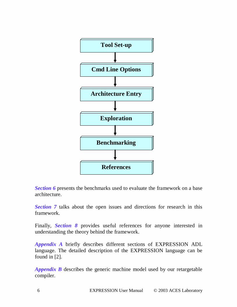
Section 6 presents the benchmarks used to evaluate the framework on a base architecture. Section 7 talks about the open issues and directions for research in this framework. Finally, Section 8 provides useful references for anyone interested in understanding the theory behind the framework. Appendix A briefly describes different sections of EXPRESSION ADL language. The detailed description of the EXPRESSION language can be found in [2]. Appendix B describes the generic machine model used by our retargetable compiler.
Tool Set-up
Cmd L ine Options
Benchmarking
Architecture Entry
Exploration
References
7 EXPRESSION User Manual © 2003 ACES Laboratory
1.2. Exploration Features Suppor ted in This Release Release 1.0 of the EXPRESSION toolkit supports the following exploration features: 1. ISA Exploration
Adding new complex instructions (Section 5.1.1). Changing register accessibility (Section 5.1.2).
2. Pipeline Exploration
Adding a single/multi cycle functional unit (Section 5.2.1). Adding a new pipelined functional unit (Section 5.2.2). Deleting a pipeline path (Section 5.2.3).
3. Memory Subsystem Exploration
Modifying access times of caches/ memories (Section 5.3.1). Modifying associativity of caches (Section 5.3.2). Changing sizes of caches/memories (Section 5.3.3). Adding new memory components in the memory subsystem (Section 5.3.4).
1.3. Recommended System Configuration The EXPRESSION toolkit has been tested on the following system: System: OS Name: M icrosoft Windows XP Professional Version: 5.1.2600 Build 2600 System Type: X86-based PC Processor : x86 Family 15 Model 1 Stepping 2 GenuineIntel ~1 Ghz Total Physical Memory: 512.00 MB Total Vir tual Memory: 1.72 GB Page File Space: 1.22 GB Development Platform: Visual C++ 6.0 Enterpr ise Edition
8 EXPRESSION User Manual © 2003 ACES Laboratory
1.4. Contact To give comments, feedback or report bugs, send email to: [email protected]
9 EXPRESSION User Manual © 2003 ACES Laboratory
2. EXPRESSION Toolkit Setup The current release of EXPRESSION can be downloaded from http://www.cecs.uci.edu/~express There are two main components in EXPRESSION: the EXPRESS compiler and the SIMPRESS simulator. This tool-kit is implemented with Microsoft Visual C++ 6.0 on an i686 machine running Microsoft Windows XP. It has also been tested on Microsoft Windows NT and Windows 2000. A Sparc/Solar is 2.7 machine is also required for preprocessing an input application in C using a GCC-based front-end. However, this latter step can also be performed from http://www.cecs.uci.edu/cgi-bin/cgiwrap/sudeep/file_upload.cgi by uploading the C application to the server which generates the required files for the EXPRESSION toolkit, in which case a Sparc/Solar is 2.7 machine is not required. EXPRESS is a retargetable compiler centered around a generic machine (described in Appendix B). An application in C is preprocessed by the GCC-based front-end to generate front-end files, <f i l ename>. pr ocs and <f i l ename>. def s using the generic machine Instruction Set Architecture (ISA). EXPRESS then reads the front-end files, builds an Intermediate Representation (IR) amenable to different optimizations and targets the architecture described in an EXPRESSION ADL (Architecture Description Language) description. The output of EXPRESS is a special assembly file named <f i l ename>_DUMP_I R_AFTER_REGALLOC. t xt SIMPRESS reads the special assembly file, simulates the running of assembly on an architecture template generated from the ADL description and finally generates area, power, and performance numbers including cycle count and memory usage statistics. The purpose of the simulator is to assess the efficacy of the code generated by the EXPRESS compiler for the given architecture.
10 EXPRESSION User Manual © 2003 ACES Laboratory
The EXPRESSION tool-kit also comes with a GUI front-end to schematically enter the architecture connectivity and instruction set description. The GUI back-end converts the schematic description and instruction set description into EXPRESSION ADL format. For details on EXPRESSION ADL, please refer to [2]. 2.1. EXPRESSION Package Unzipping acesMI PS. zi p yields the following directories:
• scr i pt s : Useful scripts for preprocessing the input application, and • expr : EXPRESS and SIMPRESS source code. • benchmar ks : Applications in C that we tested our system on.
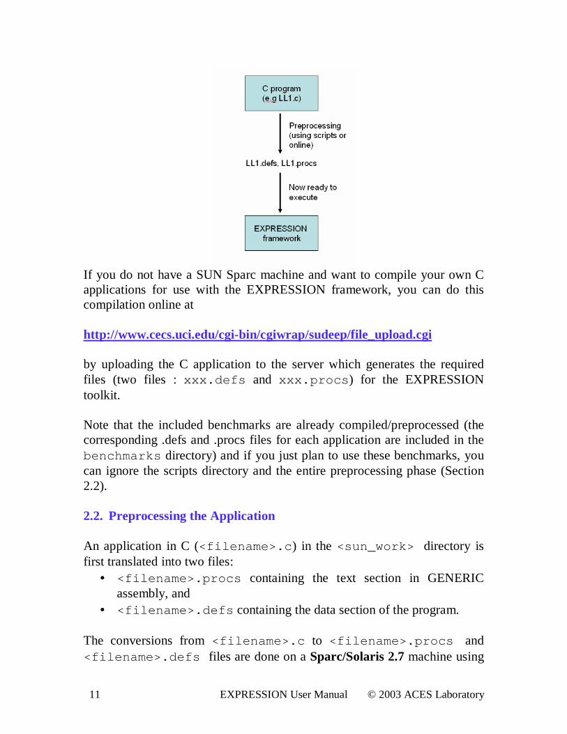
(Livermore loops and Multimedia kernels) The objective is to run the applications in the benchmar ks directory through the EXPRESSION framework comprising EXPRESS and SIMPRESS. First, copy the files in the expr directory to a suitable work directory on an i686 machine. This directory is referred to as <wor k> directory in Section 2.3. Then copy the files in the scr i pt s directory to a suitable scripts directory (<scr i pt s_di r >) on a Sparc/Solar is 2.7 machine. This step is for anyone wishing to compile C applications other than those provided in the benchmark suite included with the release. The EXPRESSION framework executes a C application only after it has been compiled/preprocessed first, using the scripts in this directory to generate two files – xxx. def s and xxx. pr ocs where xxx is the name of the C file (see figure below).
11 EXPRESSION User Manual © 2003 ACES Laboratory
If you do not have a SUN Sparc machine and want to compile your own C applications for use with the EXPRESSION framework, you can do this compilation online at http://www.cecs.uci.edu/cgi-bin/cgiwrap/sudeep/file_upload.cgi by uploading the C application to the server which generates the required files (two files : xxx. def s and xxx. pr ocs ) for the EXPRESSION toolkit. Note that the included benchmarks are already compiled/preprocessed (the corresponding .defs and .procs files for each application are included in the benchmar ks directory) and if you just plan to use these benchmarks, you can ignore the scripts directory and the entire preprocessing phase (Section 2.2). 2.2. Preprocessing the Application An application in C (<f i l ename>. c ) in the <sun_wor k> directory is first translated into two files:
• <f i l ename>. pr ocs containing the text section in GENERIC assembly, and
• <f i l ename>. def s containing the data section of the program. The conversions from <f i l ename>. c to <f i l ename>. pr ocs and <f i l ename>. def s files are done on a Sparc/Solar is 2.7 machine using
12 EXPRESSION User Manual © 2003 ACES Laboratory
a GCC-based front-end tool provided in the release package. Before running the scripts, go to <scr i pt s_di r >. Give execute permissions to the files in the <scr i pt s_di r > directory. Copy the benchmarks (<f i l ename>. c ) to be run to a work directory, <sun_wor k>. Open mi ps2expr - al l in an editor and set the variable SCR_PATH to the path to <scr i pt s_di r >. Save mi ps2expr - al l and change directory to <sun_wor k>. Run the following commands in sequence to perform the conversions.
1. csh; set pat h = ( <pat h t o scr i pt s_di r > $pat h) 2. mi ps- f e- al l <f i l ename>. c 3. mi ps2expr - al l <f i l ename>
The generated files (<f i l ename>. pr ocs and <f i l ename>. def s ) will be referred to as benchmarks in Section 2.3. Note that if you do not have a SUN Sparc machine and want to compile your own C applications for use with the EXPRESSION framework, you can do this compilation online at http://www.cecs.uci.edu/cgi-bin/cgiwrap/sudeep/file_upload.cgi by uploading the C application to the server which generates the required files (<f i l ename>. pr ocs and <f i l ename>. def s ) for the EXPRESSION toolkit. 2.3 . EXPRESSION Flow To begin with, we take a MIPS-R4000 based architecture, developed in our ACES laboratory. We call this architecture, acesMIPS. All the subsequent sections will frequently refer to this architecture for the purpose of illustrations. The EXPRESSION ADL description of acesMIPS is available in <wor k>\ acesMI PSDl l \ bi n\ Exampl e_acesMI PS. xmd. The complete flow from setting up the framework followed by the loading of acesMIPS architecture in graphical user interface (GUI) to the evaluation of the architecture consists of following steps in sequence:
(1) The run directory is <wor k>\ acesMI PSDl l \ bi n. Copy all the benchmarks ( <f i l ename>. pr ocs and <f i l ename>. def s ) to be run to this directory.
13 EXPRESSION User Manual © 2003 ACES Laboratory
(2) Invoke Microsoft Visual C++ (of Microsoft Visual Studio 6.0) and open the workspace <wor k>\ acesMI PS. dsw. In the FileView, following projects should appear in this workspace:
acesMIPS Base Class Lib acesMIPS Build System Lib acesMIPS Derived Class Lib acesMIPS Simulator Functions Lib acesMIPSConsole acesMIPSDll acesMIPSfuncSimulator expression console expression dll graphViz pcProGUI
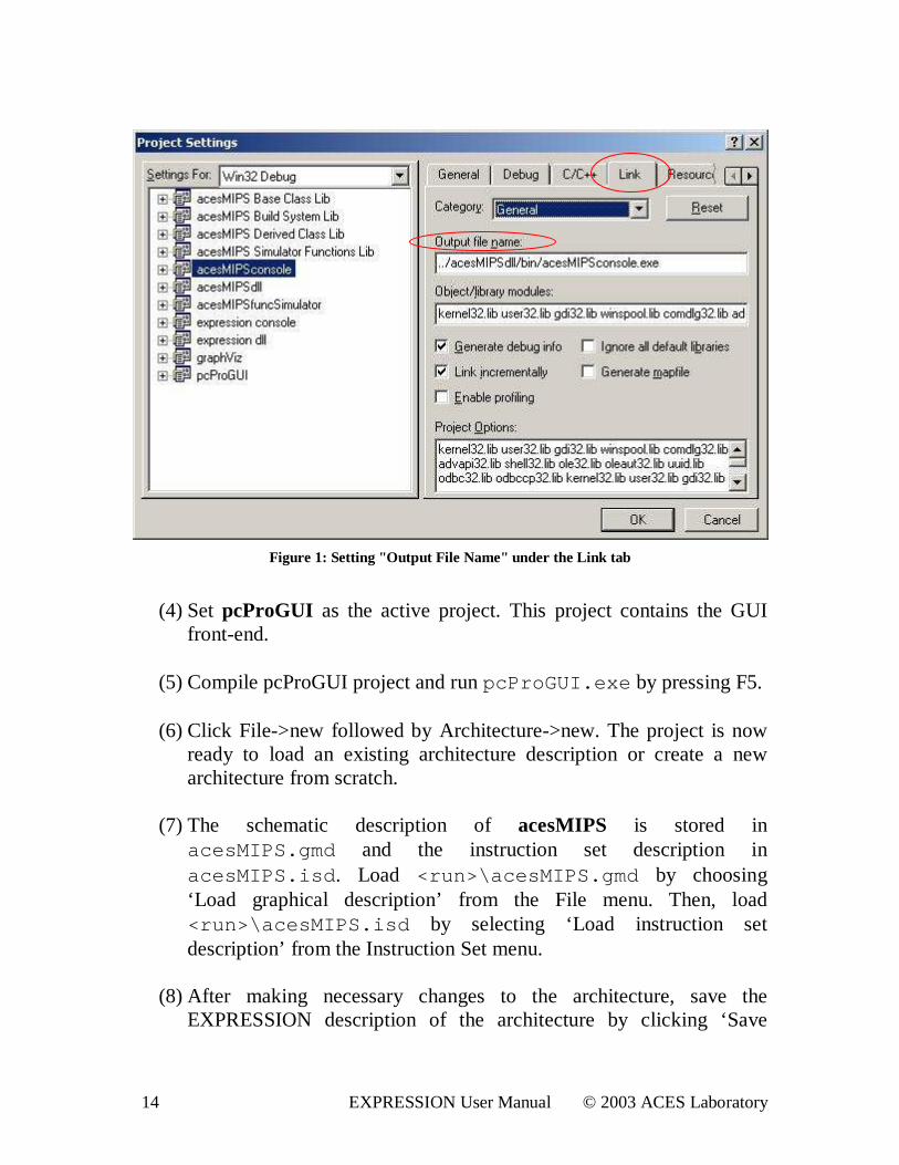
(3) Select acesMIPSConsole from the Workspace window and press ALT
+ F7. This invokes the Settings window for acesMIPSConsole project. (shown in Fig. 1) Make sure you have the following Settings for the projects:
a. In the Link tab of the settings window for the ‘General’ Category, the ‘Output file name’ of the projects should be set as follows:
i. acesMIPS console: . . \ acesMI PSdl l \ bi n\ acesMI PSconsol e. exe
ii. acesMIPSdll: . . \ acesMI PSdl l \ bi n\ acesMI PSdl l . dl l
iii. expression console: . . \ acesMI PSdl l \ bi n\ expr essi on consol e. exe
iv. expression dll: . . \ acesMI PSdl l \ bi n\ expr essi on dl l . dl l
v. graphViz: . . \ . . \ acesMI PSDl l \ bi n\ gr aphVi z. dl l
vi. pcProGUI: . . \ acesMI PSdl l \ bi n\ pcPr oGUI . exe
b. In the Debug tab for the ‘General’ Category, the ‘Working Directory’ for the projects ‘acesMIPS console’ , ‘ expression console’ and ‘pcProGUI’ should all be set to the run directory, <wor k>\ acesMI PSDl l \ bi n.
14 EXPRESSION User Manual © 2003 ACES Laboratory
Figure 1: Setting " Output File Name" under the L ink tab
(4) Set pcProGUI as the active project. This project contains the GUI
front-end. (5) Compile pcProGUI project and run pcPr oGUI . exe by pressing F5.
(6) Click File->new followed by Architecture->new. The project is now
ready to load an existing architecture description or create a new architecture from scratch.
(7) The schematic description of acesMIPS is stored in
acesMI PS. gmd and the instruction set description in acesMI PS. i sd. Load <r un>\ acesMI PS. gmd by choosing ‘Load graphical description’ from the File menu. Then, load <r un>\ acesMI PS. i sd by selecting ‘Load instruction set description’ from the Instruction Set menu.
(8) After making necessary changes to the architecture, save the
EXPRESSION description of the architecture by clicking ‘Save
15 EXPRESSION User Manual © 2003 ACES Laboratory
EXPRESSION description’ from the File menu. Choose <r un>\ acesMI PS. xmd to save the ADL description.
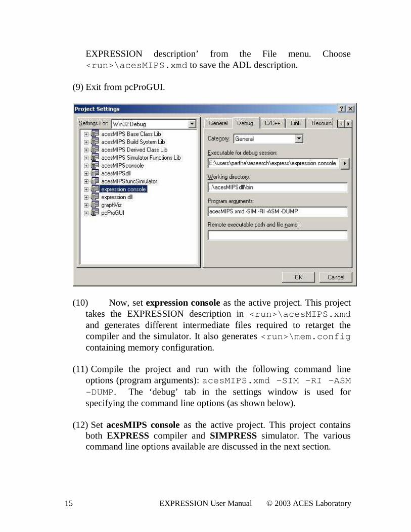
(9) Exit from pcProGUI.
(10) Now, set expression console as the active project. This project takes the EXPRESSION description in <r un>\ acesMI PS. xmd and generates different intermediate files required to retarget the compiler and the simulator. It also generates <r un>\ mem. conf i g containing memory configuration.
(11) Compile the project and run with the following command line
options (program arguments): acesMI PS. xmd –SI M –RI –ASM –DUMP. The ‘debug’ tab in the settings window is used for specifying the command line options (as shown below).
(12) Set acesMIPS console as the active project. This project contains
both EXPRESS compiler and SIMPRESS simulator. The various command line options available are discussed in the next section.
16 EXPRESSION User Manual © 2003 ACES Laboratory
(13) Compile the project, set the command line options (discussed in Section 3) and run the project.
The acesMIPS console application generates the number of cycles, memory usage and other statistics in <r un>/ <f i l ename>. pwr St at s . These performance numbers will guide the designers to make favorable choices to steer the effective exploration of the architectural design space.
17 EXPRESSION User Manual © 2003 ACES Laboratory
3. Command L ine Options EXPRESS switches that are supported in this release:
• -ISel (Instruction Selection): Convert a set of generic opcodes into a set of target opcodes.
• -RA (Register Allocation): Each operand in an instruction is bound to a target register based on its register accessibility.
• -Tbz (Trailblazing Percolation Scheduling): Perform Trailblazing [4] assuming that the latency of each operation is 1 cycle.
• -PipeTbz (Pipelined Trailblazing): Based on the reservation tables automatically generated ([3]) from the datapath, perform Trailblazing Percolation Scheduling.
• -EXPR –ENAME “<xmd filename>” : Specify the input ADL file name for pipelined trailblazing.
• -PreSch (Prescheduling Transformations): Perform different target independent optimizations.
o Dead-code Elimination o Copy propagation
• -pIList: Dump Instruction List on the console. • -pHTG: Dump Hierarchical Task Graph on the console. • -pCFG: Dump Control Flow Graph on the console. • -pASM: Generate assembly code run-able on a native machine. • -pDUMP: Generate special assembly output (IR dump) understood by
the SIMPRESS simulator. • -name “<prefix>” : Use “<prefix>” to prefix the generated assembly
file name as well as the generated IR dump file name.
SIMPRESS switches supported: • -sRA: Run cycle-accurate simulation after Register Allocation • -fsRA: Run functional simulation after Register Allocation • -memCfg mem.config: Use the memory configuration specified in
mem.config file. To run EXPRESS without any optimization, which performs only instruction selection and register allocation and then run SIMPRESS, use the following command line options: (Assume input files are <f i l ename>. pr ocs and <f i l ename>. def s )
18 EXPRESSION User Manual © 2003 ACES Laboratory
<f i l ename>. pr ocs <f i l ename>. def s –pDUMP –name “ <f i l ename>” –I Sel –RA - memCf g mem. conf i g –sRA To run with different target-independent optimizations and Pipelined Trailblazing, type the following as command line options: <f i l ename>. pr ocs <f i l ename>. def s –pDUMP –name “ <f i l ename>” –I Sel –RA –EXPR –ENAME “ acesMI PS. xmd” –pi peTbz –Tbz –Pr eSch –memCf g mem. conf i g –sRA To run the above optimizations and dump the instruction list, the control flow graph and the hierarchical task graph after register allocation, use the following command line options: <f i l ename>. pr ocs <f i l ename>. def s –pDUMP –name “ <f i l ename>” –I Sel –RA –EXPR –ENAME “ acesMI PS. xmd” –pi peTbz –Tbz –Pr eSch –memCf g mem. conf i g –pI Li st –pCFG –pHTG –sRA
� Please also note that the command line options can be specified in any order .
19 EXPRESSION User Manual © 2003 ACES Laboratory
4. Architecture Entry The VSAT-GUI [1] is the front end to the EXPRESSION framework for architectural design space exploration. This release focuses on the acesMIPS architecture for exploration. We will show in section 5, how the framework can be used to perform architectural exploration. This section is broken up into two tutorials. The objective of the first tutorial (Section 4.1) is to familiarize with the representation of different architectural components and instruction set of acesMIPS architecture. The second tutorial (Section 4.2) teaches how to add a new component in the GUI. 4.1. Tutor ial I The aim of this tutorial is to load the acesMIPS design in GUI and to get familiar with the graphical environment.
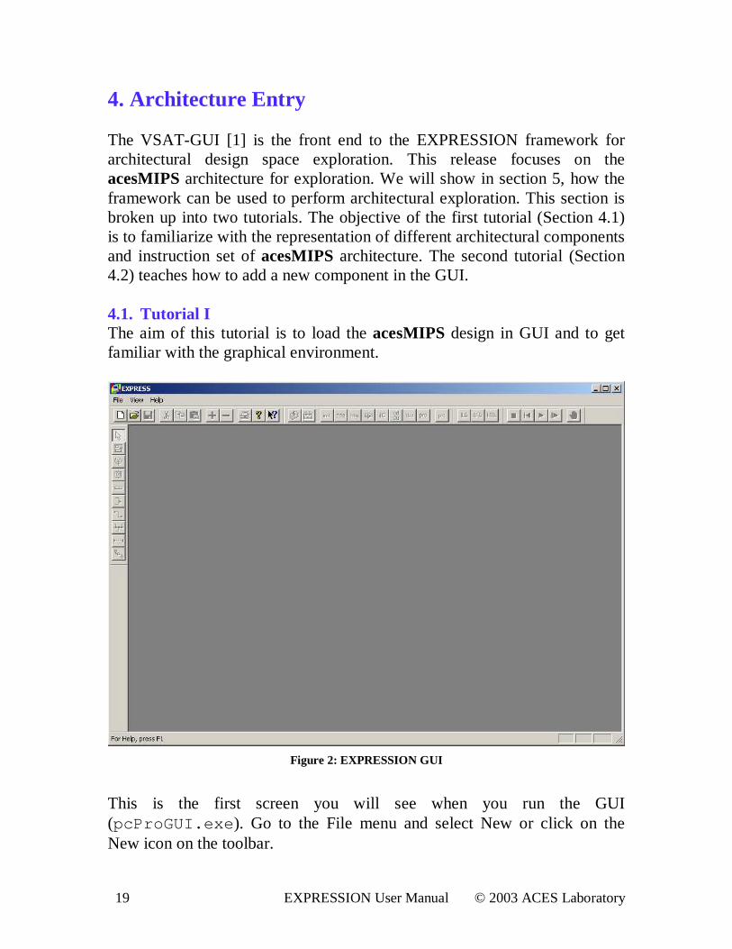
Figure 2: EXPRESSION GUI
This is the first screen you will see when you run the GUI (pcPr oGUI . exe). Go to the File menu and select New or click on the New icon on the toolbar.

20 EXPRESSION User Manual © 2003 ACES Laboratory
Next, go to the Architecture menu option and select New. You should now see the following screen.
Figure 3: Architecture Entry View
Now, from the “File” menu, choose the option to Load a Graphical Machine Description. Select and open graphical machine description file, <r un>\ acesMI PS. gmd. This graphical machine description file contains a layout of all the components including pipeline stages, architecture units, register files and the memory subsystem in acesMIPS architecture. Then, from the “ Instruction Set” menu, select the option to Load an Instruction Set Description. Select and open instruction set description file, <r un>\ acesMI PS. i sd. This instruction set description file contains the description of acesMIPS instruction set. Clicking on any entity on the screen will bring up its properties in the Properties window. The Properties window will be overlaid on the main window.
21 EXPRESSION User Manual © 2003 ACES Laboratory
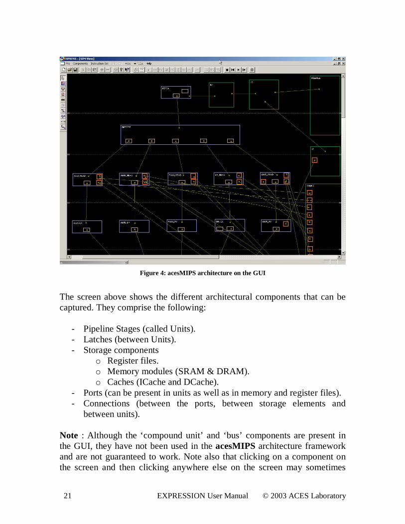
Figure 4: acesMIPS architecture on the GUI
The screen above shows the different architectural components that can be captured. They comprise the following:
- Pipeline Stages (called Units). - Latches (between Units). - Storage components
o Register files. o Memory modules (SRAM & DRAM). o Caches (ICache and DCache).
- Ports (can be present in units as well as in memory and register files). - Connections (between the ports, between storage elements and
between units).
Note : Although the ‘ compound unit’ and ‘bus’ components are present in the GUI, they have not been used in the acesMIPS architecture framework and are not guaranteed to work. Note also that clicking on a component on the screen and then clicking anywhere else on the screen may sometimes
22 EXPRESSION User Manual © 2003 ACES Laboratory
cause a ‘ghost’ (a residual image) of that component to appear on the screen. This is normal and vanishes when you click another component on the screen.
4.1.1. Architectural Components Specification In this section, we gloss over the details of the aforementioned architectural components.
4.1.1.1. Unit
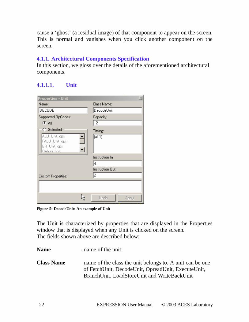
Figure 5: DecodeUnit: An example of Unit
The Unit is characterized by properties that are displayed in the Properties window that is displayed when any Unit is clicked on the screen. The fields shown above are described below: Name - name of the unit Class Name - name of the class the unit belongs to. A unit can be one
of FetchUnit, DecodeUnit, OpreadUnit, ExecuteUnit, BranchUnit, LoadStoreUnit and WriteBackUnit
23 EXPRESSION User Manual © 2003 ACES Laboratory
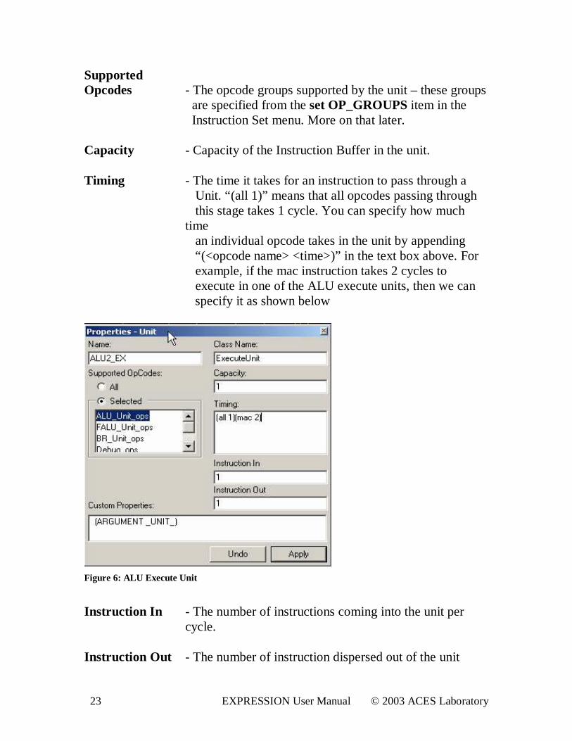
Suppor ted Opcodes - The opcode groups supported by the unit – these groups are specified from the set OP_GROUPS item in the
Instruction Set menu. More on that later.
Capacity - Capacity of the Instruction Buffer in the unit. Timing - The time it takes for an instruction to pass through a
Unit. “ (all 1)” means that all opcodes passing through this stage takes 1 cycle. You can specify how much time an individual opcode takes in the unit by appending “ (<opcode name> <time>)” in the text box above. For example, if the mac instruction takes 2 cycles to execute in one of the ALU execute units, then we can specify it as shown below
Figure 6: ALU Execute Unit
Instruction I n - The number of instructions coming into the unit per
cycle. Instruction Out - The number of instruction dispersed out of the unit
24 EXPRESSION User Manual © 2003 ACES Laboratory
Custom Proper ties - Other miscellaneous properties. For instance,
‘ARGUMENT _UNIT_’ needs to be specified for the execute units and is used in pipeline trailblazing.
4.1.1.2. Latch
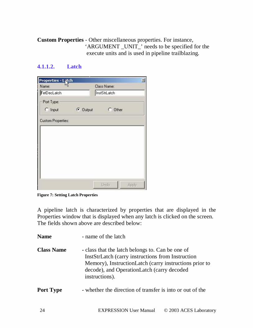
Figure 7: Setting Latch Proper ties
A pipeline latch is characterized by properties that are displayed in the Properties window that is displayed when any latch is clicked on the screen. The fields shown above are described below: Name - name of the latch Class Name - class that the latch belongs to. Can be one of
InstStrLatch (carry instructions from Instruction Memory), InstructionLatch (carry instructions prior to decode), and OperationLatch (carry decoded instructions).
Por t Type - whether the direction of transfer is into or out of the
25 EXPRESSION User Manual © 2003 ACES Laboratory
latch. Each unit has latches associated with it and these are specified by creating a latch within the unit (which specifies an output or other type latch) or a
connection from a latch in another element to the unit (implicitly specifying an input from the latch of that unit)
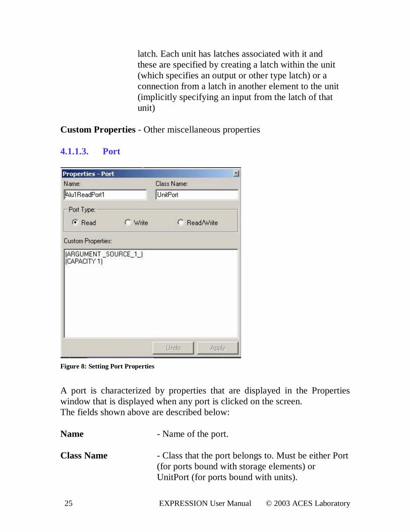
Custom Proper ties - Other miscellaneous properties 4.1.1.3. Por t
Figure 8: Setting Por t Proper ties
A port is characterized by properties that are displayed in the Properties window that is displayed when any port is clicked on the screen. The fields shown above are described below: Name - Name of the port. Class Name - Class that the port belongs to. Must be either Port
(for ports bound with storage elements) or UnitPort (for ports bound with units).
26 EXPRESSION User Manual © 2003 ACES Laboratory
Por t Type - Specifies whether the port is a read, write or a
read/write Port. Custom Proper ties - Other miscellaneous properties. For instance
‘ARGUMENT _SOURCE_1_’ indicates that this port will serve as the first source for operations that are associated with the ALU1 unit. ‘CAPACITY 1’ indicates that only 1 value can be read from the port.
4.1.1.4. Connection
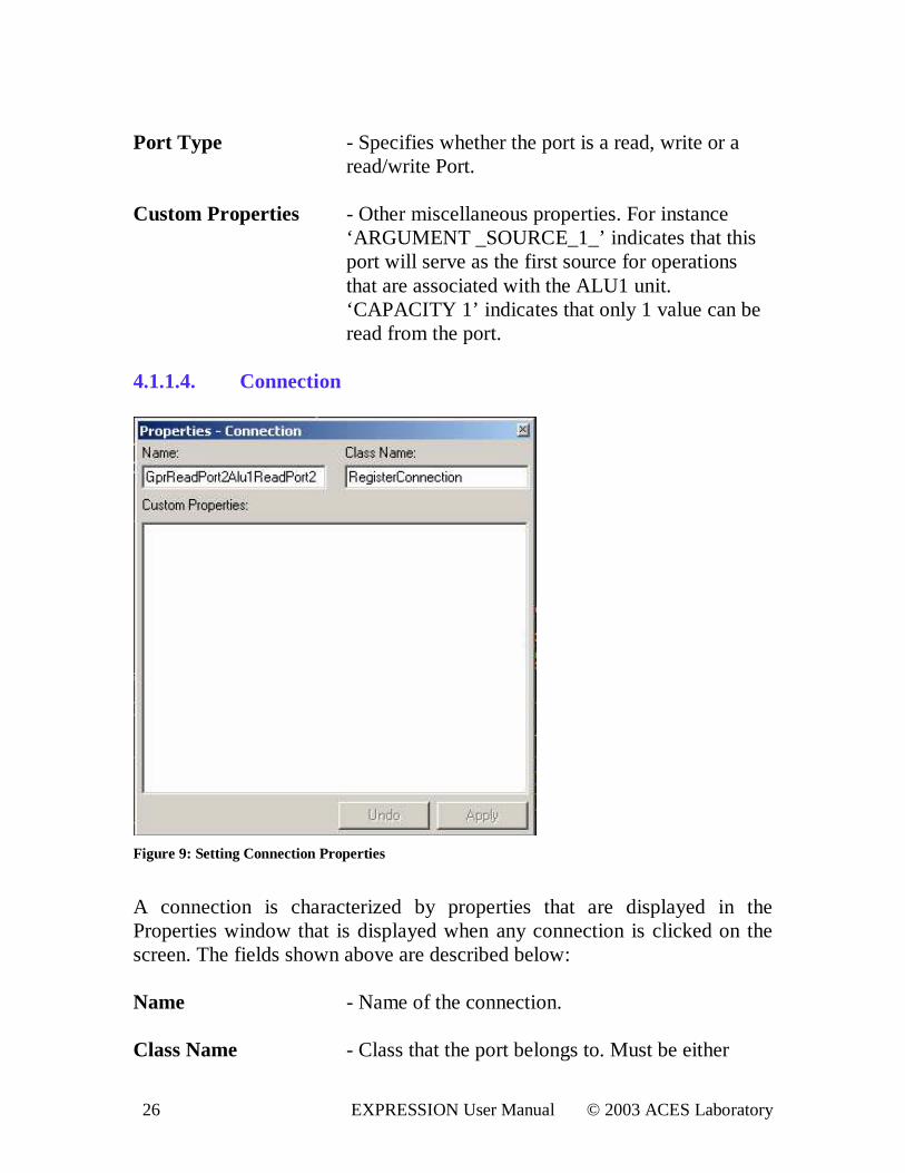
Figure 9: Setting Connection Proper ties
A connection is characterized by properties that are displayed in the Properties window that is displayed when any connection is clicked on the screen. The fields shown above are described below: Name - Name of the connection. Class Name - Class that the port belongs to. Must be either

27 EXPRESSION User Manual © 2003 ACES Laboratory
RegisterConnection (for a connection between units and a register file) or MemoryConnection (for a connection between unit and a memory element). Custom Proper ties - Other miscellaneous properties. 4.1.1.5. Storage (Register File)
Figure 10: Register File Proper ties
A register file storage element is characterized by properties that are displayed in the Properties window that is displayed when the storage element is clicked on the screen. The fields shown above are described below: Name - Name of register file. Class Name - Class of the register file. Can only be Storage. Width - Width of register file in bits.
28 EXPRESSION User Manual © 2003 ACES Laboratory
Size - Number of registers in the register file. Mnemonic - Prefix to be used for the registers in assembly
formats. For example, General Purpose Register file has registers with prefix “R” .
Custom Proper ties - Other miscellaneous properties. 4.1.1.6. Storage (Cache)
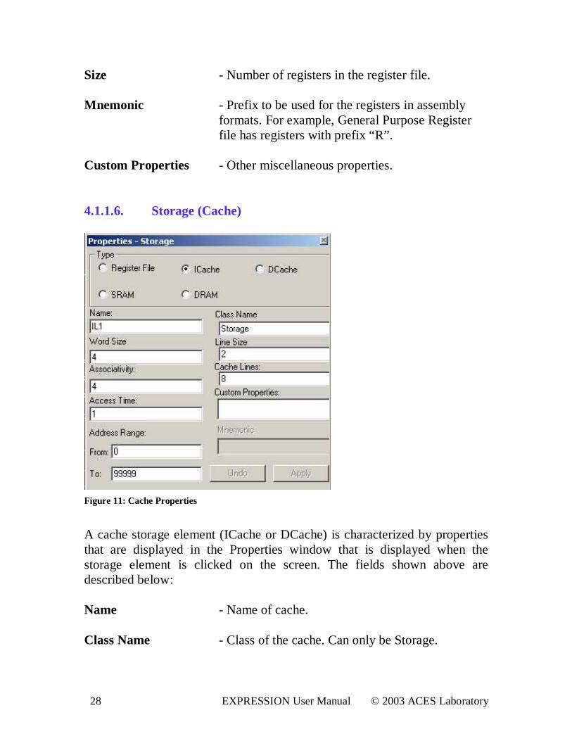
Figure 11: Cache Proper ties
A cache storage element (ICache or DCache) is characterized by properties that are displayed in the Properties window that is displayed when the storage element is clicked on the screen. The fields shown above are described below: Name - Name of cache. Class Name - Class of the cache. Can only be Storage.
29 EXPRESSION User Manual © 2003 ACES Laboratory
Word Size - Number of bytes in a word. Line Size - Number of words in a line. Associativity - Associativity level of cache. Cache lines - Number of lines in cache. Access Time - Time to access cache (in cycles). Address Range - Range of addresses associated with cache. Custom Proper ties - Other miscellaneous properties. 4.1.1.7. Storage (RAM)
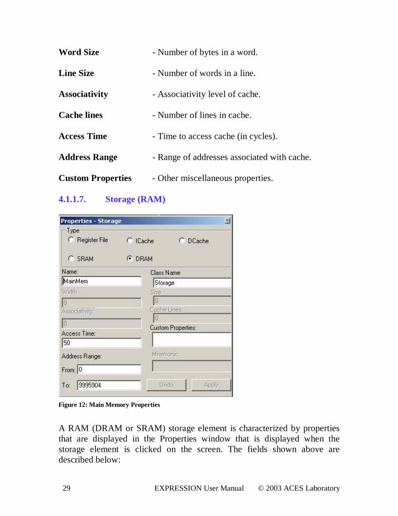
Figure 12: Main Memory Proper ties
A RAM (DRAM or SRAM) storage element is characterized by properties that are displayed in the Properties window that is displayed when the storage element is clicked on the screen. The fields shown above are described below:
30 EXPRESSION User Manual © 2003 ACES Laboratory
Name - Name of memory. Class Name - Class of the memory element. Can only be
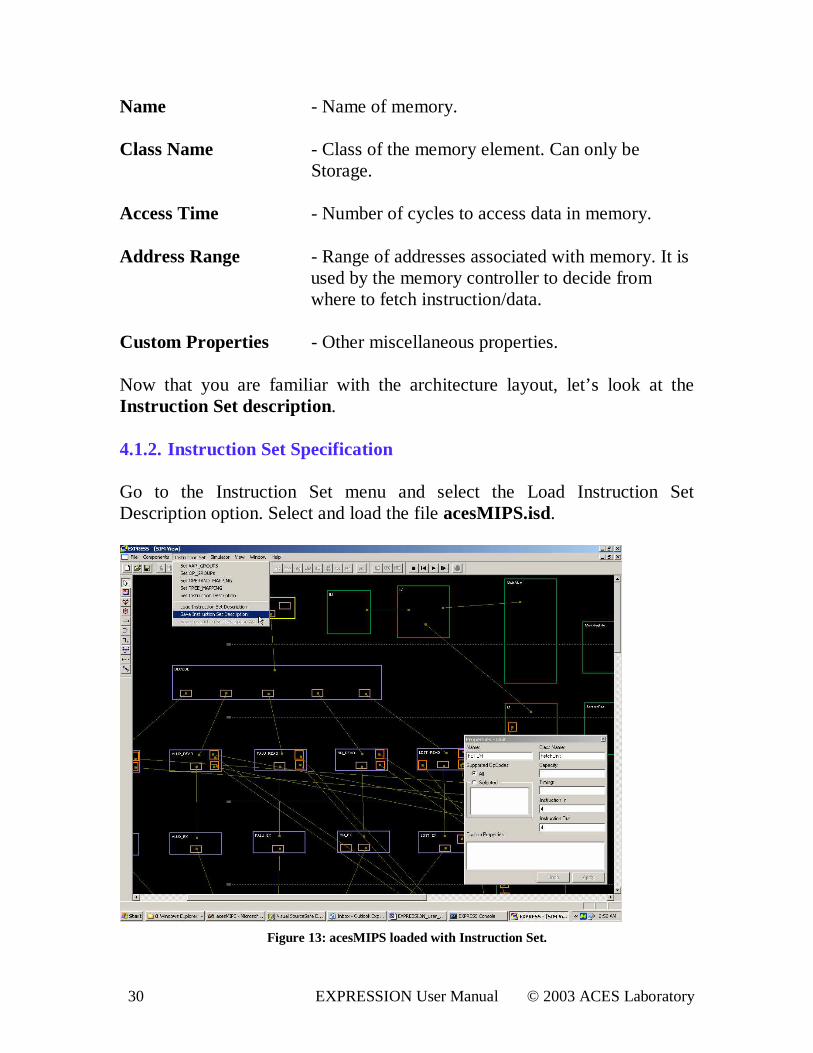
Storage. Access Time - Number of cycles to access data in memory. Address Range - Range of addresses associated with memory. It is used by the memory controller to decide from where to fetch instruction/data. Custom Proper ties - Other miscellaneous properties. Now that you are familiar with the architecture layout, let’ s look at the Instruction Set descr iption. 4.1.2. Instruction Set Specification Go to the Instruction Set menu and select the Load Instruction Set Description option. Select and load the file acesMIPS.isd.
Figure 13: acesMIPS loaded with Instruction Set.
31 EXPRESSION User Manual © 2003 ACES Laboratory
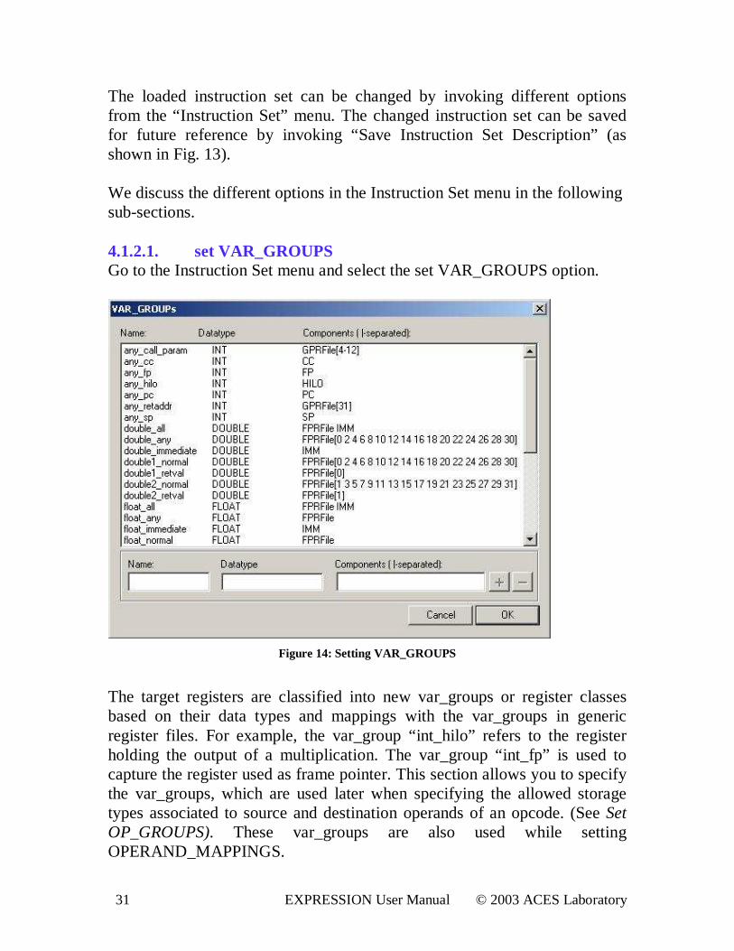
The loaded instruction set can be changed by invoking different options from the “ Instruction Set” menu. The changed instruction set can be saved for future reference by invoking “Save Instruction Set Description” (as shown in Fig. 13). We discuss the different options in the Instruction Set menu in the following sub-sections. 4.1.2.1. set VAR_GROUPS Go to the Instruction Set menu and select the set VAR_GROUPS option.
Figure 14: Setting VAR_GROUPS
The target registers are classified into new var_groups or register classes based on their data types and mappings with the var_groups in generic register files. For example, the var_group “ int_hilo” refers to the register holding the output of a multiplication. The var_group “ int_fp” is used to capture the register used as frame pointer. This section allows you to specify the var_groups, which are used later when specifying the allowed storage types associated to source and destination operands of an opcode. (See Set OP_GROUPS). These var_groups are also used while setting OPERAND_MAPPINGS.
32 EXPRESSION User Manual © 2003 ACES Laboratory
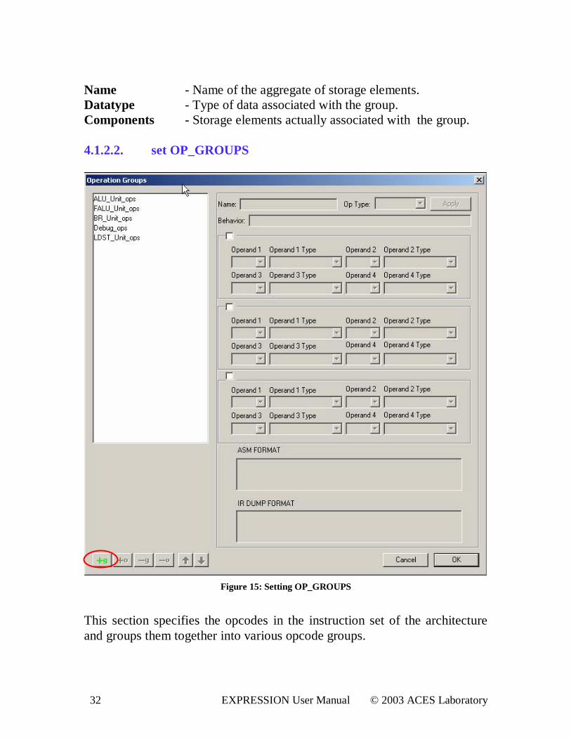
Name - Name of the aggregate of storage elements. Datatype - Type of data associated with the group. Components - Storage elements actually associated with the group. 4.1.2.2. set OP_GROUPS
Figure 15: Setting OP_GROUPS
This section specifies the opcodes in the instruction set of the architecture and groups them together into various opcode groups.
33 EXPRESSION User Manual © 2003 ACES Laboratory
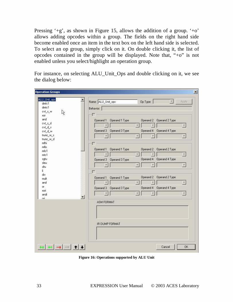
Pressing ‘+g’ , as shown in Figure 15, allows the addition of a group. ‘+o’ allows adding opcodes within a group. The fields on the right hand side become enabled once an item in the text box on the left hand side is selected. To select an op group, simply click on it. On double clicking it, the list of opcodes contained in the group will be displayed. Note that, “+o” is not enabled unless you select/highlight an operation group. For instance, on selecting ALU_Unit_Ops and double clicking on it, we see the dialog below:
Figure 16: Operations suppor ted by ALU Unit
34 EXPRESSION User Manual © 2003 ACES Laboratory
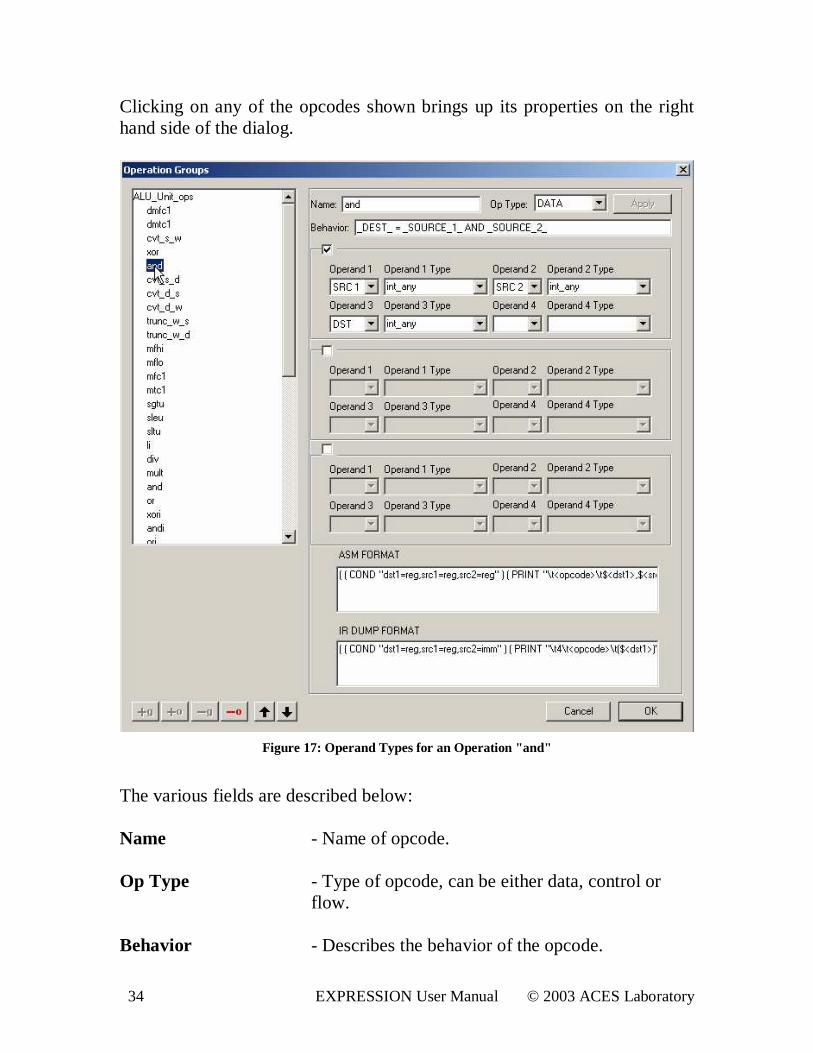
Clicking on any of the opcodes shown brings up its properties on the right hand side of the dialog.
Figure 17: Operand Types for an Operation " and"
The various fields are described below: Name - Name of opcode. Op Type - Type of opcode, can be either data, control or
flow. Behavior - Describes the behavior of the opcode.
35 EXPRESSION User Manual © 2003 ACES Laboratory
Operand X - Specifies operands in the opcode. Operand X Type - Specifies type of the operand. These types were
defined in the VAR_GROUPs section. ASM format - Specifies format for standard assembly dump
(enabled by option –pASM). IR Dump Format - Specifies format for intermediate representation
dump, which acts as assembly for the simulator. (The simulator expects the instruction format to be in the following format: <opcode> ( dst 1,
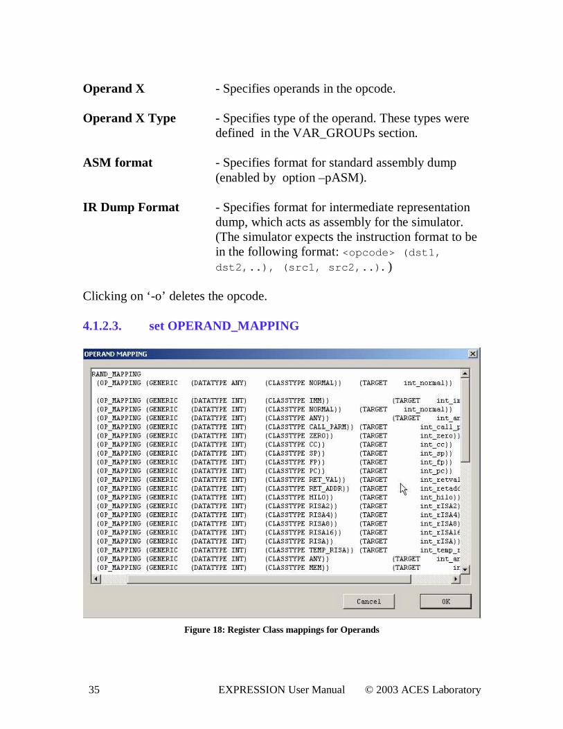
dst 2, . . ) , ( sr c1, sr c2, . . ) . ) Clicking on ‘ -o’ deletes the opcode. 4.1.2.3. set OPERAND_MAPPING
Figure 18: Register Class mappings for Operands
36 EXPRESSION User Manual © 2003 ACES Laboratory
The registers in the generic machine are classified into a set of register classes (based on types like GPRFile registers, FPRFile registers, return address register, register hard-wired to zero etc.) or var_groups (already discussed in Section 4.1.2.1). The mappings of these generic register classes to a new set of target register classes are specified in this section. 4.1.2.4. set TREE_MAPPING
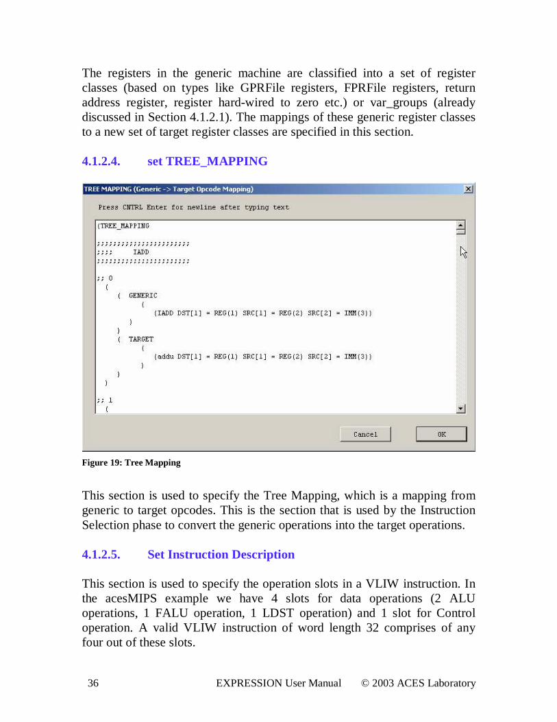
Figure 19: Tree Mapping
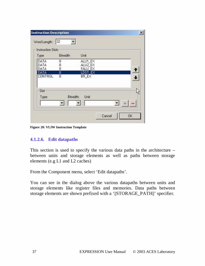
This section is used to specify the Tree Mapping, which is a mapping from generic to target opcodes. This is the section that is used by the Instruction Selection phase to convert the generic operations into the target operations. 4.1.2.5. Set Instruction Descr iption This section is used to specify the operation slots in a VLIW instruction. In the acesMIPS example we have 4 slots for data operations (2 ALU operations, 1 FALU operation, 1 LDST operation) and 1 slot for Control operation. A valid VLIW instruction of word length 32 comprises of any four out of these slots.
37 EXPRESSION User Manual © 2003 ACES Laboratory
Figure 20: VLIW Instruction Template
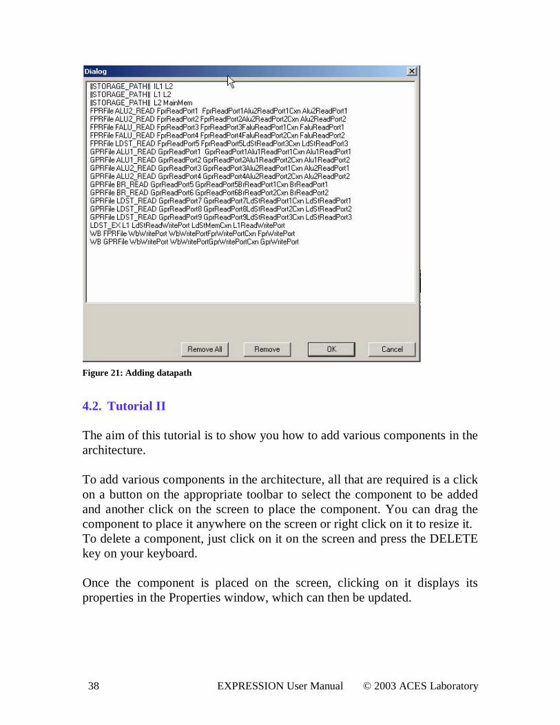
4.1.2.6. Edit datapaths This section is used to specify the various data paths in the architecture – between units and storage elements as well as paths between storage elements (e.g L1 and L2 caches) From the Component menu, select ‘Edit datapaths’ . You can see in the dialog above the various datapaths between units and storage elements like register files and memories. Data paths between storage elements are shown prefixed with a ‘ ||STORAGE_PATH||’ specifier.
38 EXPRESSION User Manual © 2003 ACES Laboratory
Figure 21: Adding datapath
4.2. Tutor ial I I The aim of this tutorial is to show you how to add various components in the architecture. To add various components in the architecture, all that are required is a click on a button on the appropriate toolbar to select the component to be added and another click on the screen to place the component. You can drag the component to place it anywhere on the screen or right click on it to resize it. To delete a component, just click on it on the screen and press the DELETE key on your keyboard. Once the component is placed on the screen, clicking on it displays its properties in the Properties window, which can then be updated.
39 EXPRESSION User Manual © 2003 ACES Laboratory
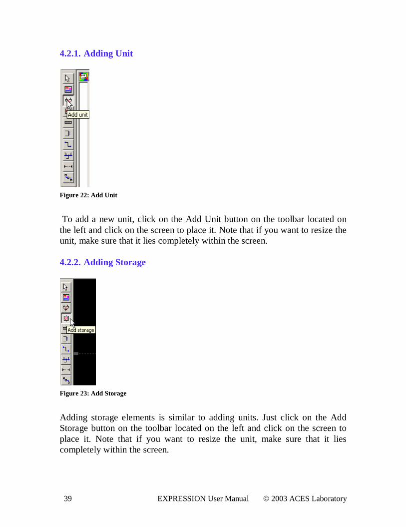
4.2.1. Adding Unit
Figure 22: Add Unit
To add a new unit, click on the Add Unit button on the toolbar located on the left and click on the screen to place it. Note that if you want to resize the unit, make sure that it lies completely within the screen. 4.2.2. Adding Storage
Figure 23: Add Storage
Adding storage elements is similar to adding units. Just click on the Add Storage button on the toolbar located on the left and click on the screen to place it. Note that if you want to resize the unit, make sure that it lies completely within the screen.
40 EXPRESSION User Manual © 2003 ACES Laboratory
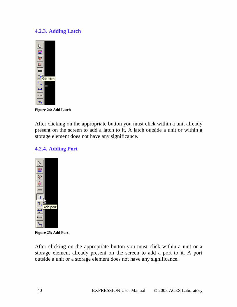
4.2.3. Adding Latch
Figure 24: Add Latch
After clicking on the appropriate button you must click within a unit already present on the screen to add a latch to it. A latch outside a unit or within a storage element does not have any significance. 4.2.4. Adding Por t
Figure 25: Add Por t
After clicking on the appropriate button you must click within a unit or a storage element already present on the screen to add a port to it. A port outside a unit or a storage element does not have any significance.
41 EXPRESSION User Manual © 2003 ACES Laboratory
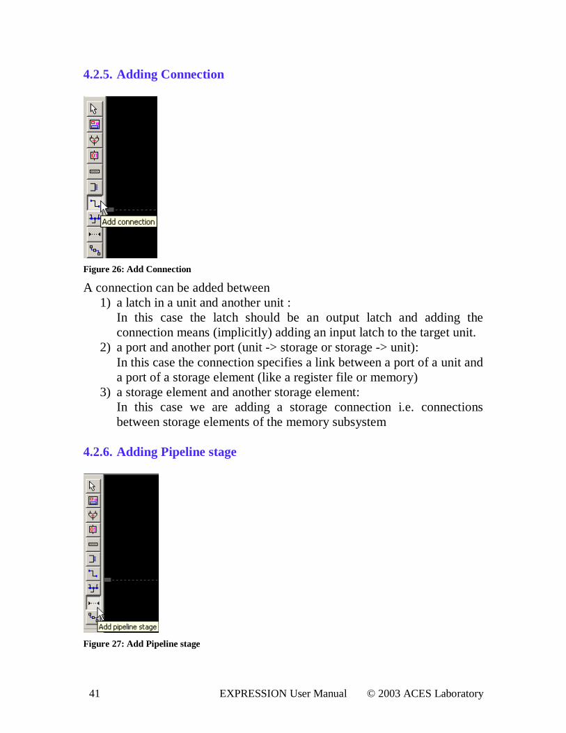
4.2.5. Adding Connection
Figure 26: Add Connection
A connection can be added between 1) a latch in a unit and another unit :
In this case the latch should be an output latch and adding the connection means (implicitly) adding an input latch to the target unit.
2) a port and another port (unit -> storage or storage -> unit): In this case the connection specifies a link between a port of a unit and a port of a storage element (like a register file or memory)
3) a storage element and another storage element: In this case we are adding a storage connection i.e. connections between storage elements of the memory subsystem
4.2.6. Adding Pipeline stage
Figure 27: Add Pipeline stage
42 EXPRESSION User Manual © 2003 ACES Laboratory
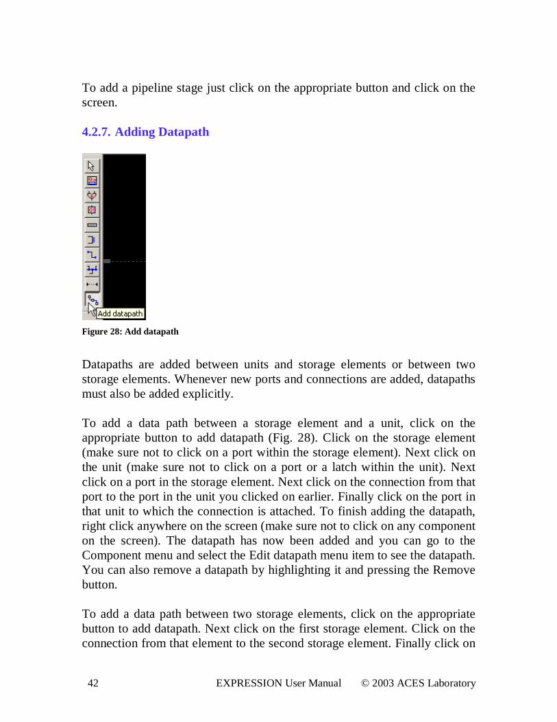
To add a pipeline stage just click on the appropriate button and click on the screen. 4.2.7. Adding Datapath
Figure 28: Add datapath
Datapaths are added between units and storage elements or between two storage elements. Whenever new ports and connections are added, datapaths must also be added explicitly. To add a data path between a storage element and a unit, click on the appropriate button to add datapath (Fig. 28). Click on the storage element (make sure not to click on a port within the storage element). Next click on the unit (make sure not to click on a port or a latch within the unit). Next click on a port in the storage element. Next click on the connection from that port to the port in the unit you clicked on earlier. Finally click on the port in that unit to which the connection is attached. To finish adding the datapath, right click anywhere on the screen (make sure not to click on any component on the screen). The datapath has now been added and you can go to the Component menu and select the Edit datapath menu item to see the datapath. You can also remove a datapath by highlighting it and pressing the Remove button. To add a data path between two storage elements, click on the appropriate button to add datapath. Next click on the first storage element. Click on the connection from that element to the second storage element. Finally click on
43 EXPRESSION User Manual © 2003 ACES Laboratory
the second storage element. To finish adding the datapath, right click anywhere on the screen (make sure not to click on any component on the screen). The datapath has now been added and you can go to the Component menu and select the Edit datapath menu item to see the datapath. You can also remove a datapath by highlighting it and pressing the Remove button.
44 EXPRESSION User Manual © 2003 ACES Laboratory
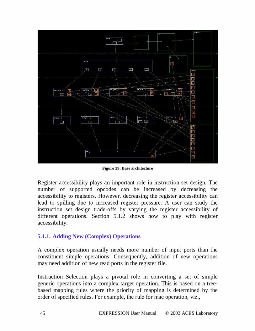
5. Design Space Exploration We present in this section, some of the exploration directions, which are important for a system designer. An architectural modification can affect another architectural change positively or negatively. So, the designer has to do a trade-off between different performance goals, respecting the architectural constraints. For details on how to perform design space exploration of an architecture having processor, co-processor, and memory subsystem, please refer to [7] [8] [9]. The different architecture explorations comprise Instruction Set Architecture exploration, Micro-architecture exploration and Memory architecture exploration. The users should be able to follow the steps enumerated in the following sections and explore various interesting design points starting from any base architecture. For each exploration, we also present the results to be expected. The following subsections will take you through a tour of explorations starting from acesMIPS architecture as a base architecture. Fig. 29 shows a snapshot of the base architecture. It has five pipeline stages: Fetch, Decode, Operand Read, Execute and Writeback. The Operand Read and Execute stages have five parallel pipeline paths: ALU1, ALU2, Floating-Point, Branch, and Load Store. It has two register files: integer and float. It has two level of cache hierarchy with common L2 for both data and instruction. It also uses SRAM as a scratch-pad memory. 5.1 . ISA Exploration Most of the instructions of a target machine are obtained from the generic instruction set by one-to-one mapping of generic to target operations. When two or more generic operations combine together to form a target operation, we call the target operation, a complex operation. The target instruction set can be made richer by incorporation of large number of useful complex operations. A complex operation is useful for a given application, when a sequence of operations forming the complex operation is frequently used. A profiler can come up with useful complex operations to be added to a base instruction set. Another advantage of adding a complex operation is that it gets rid of extra fetch delays. Section 5.1.1 discusses how to add a complex operation.
45 EXPRESSION User Manual © 2003 ACES Laboratory
Figure 29: Base architecture
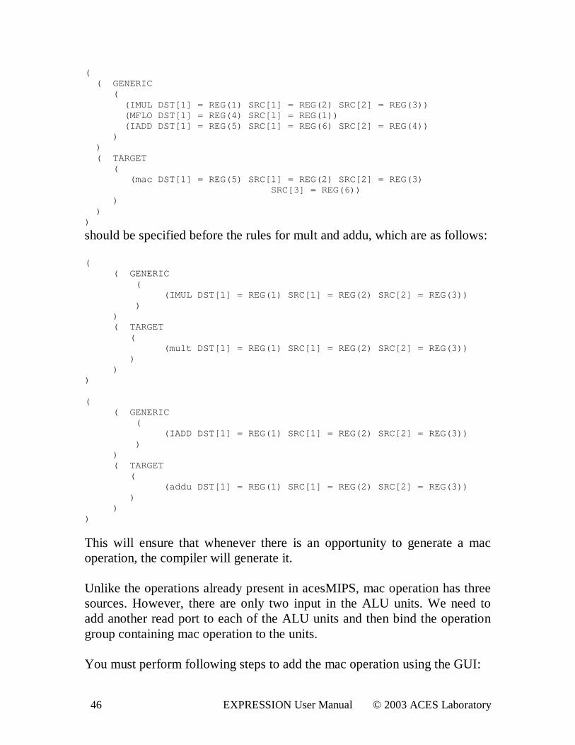
Register accessibility plays an important role in instruction set design. The number of supported opcodes can be increased by decreasing the accessibility to registers. However, decreasing the register accessibility can lead to spilling due to increased register pressure. A user can study the instruction set design trade-offs by varying the register accessibility of different operations. Section 5.1.2 shows how to play with register accessibility. 5.1.1. Adding New (Complex) Operations A complex operation usually needs more number of input ports than the constituent simple operations. Consequently, addition of new operations may need addition of new read ports in the register file. Instruction Selection plays a pivotal role in converting a set of simple generic operations into a complex target operation. This is based on a tree-based mapping rules where the priority of mapping is determined by the order of specified rules. For example, the rule for mac operation, viz.,
46 EXPRESSION User Manual © 2003 ACES Laboratory
( ( GENERI C ( ( I MUL DST[ 1] = REG( 1) SRC[ 1] = REG( 2) SRC[ 2] = REG( 3) ) ( MFLO DST[ 1] = REG( 4) SRC[ 1] = REG( 1) ) ( I ADD DST[ 1] = REG( 5) SRC[ 1] = REG( 6) SRC[ 2] = REG( 4) ) ) ) ( TARGET ( ( mac DST[ 1] = REG( 5) SRC[ 1] = REG( 2) SRC[ 2] = REG( 3) SRC[ 3] = REG( 6) ) ) ) )
should be specified before the rules for mult and addu, which are as follows: ( ( GENERI C ( ( I MUL DST[ 1] = REG( 1) SRC[ 1] = REG( 2) SRC[ 2] = REG( 3) ) ) ) ( TARGET ( ( mul t DST[ 1] = REG( 1) SRC[ 1] = REG( 2) SRC[ 2] = REG( 3) ) ) ) ) ( ( GENERI C ( ( I ADD DST[ 1] = REG( 1) SRC[ 1] = REG( 2) SRC[ 2] = REG( 3) ) ) ) ( TARGET ( ( addu DST[ 1] = REG( 1) SRC[ 1] = REG( 2) SRC[ 2] = REG( 3) ) ) ) )
This will ensure that whenever there is an opportunity to generate a mac operation, the compiler will generate it. Unlike the operations already present in acesMIPS, mac operation has three sources. However, there are only two input in the ALU units. We need to add another read port to each of the ALU units and then bind the operation group containing mac operation to the units. You must perform following steps to add the mac operation using the GUI:
47 EXPRESSION User Manual © 2003 ACES Laboratory
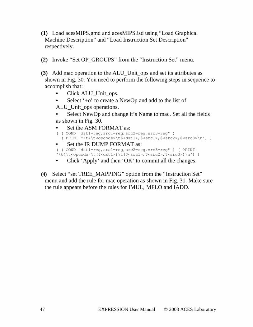
(1) Load acesMIPS.gmd and acesMIPS.isd using “Load Graphical Machine Description” and “ Load Instruction Set Description” respectively.
(2) Invoke “Set OP_GROUPS” from the “ Instruction Set” menu.
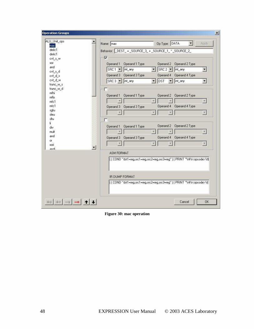
(3) Add mac operation to the ALU_Unit_ops and set its attributes as
shown in Fig. 30. You need to perform the following steps in sequence to accomplish that:
• Click ALU_Unit_ops. • Select ‘+o’ to create a NewOp and add to the list of ALU_Unit_ops operations. • Select NewOp and change it’ s Name to mac. Set all the fields as shown in Fig. 30. • Set the ASM FORMAT as: ( ( COND " dst 1=r eg, sr c1=r eg, sr c2=r eg, sr c3=r eg" ) ( PRI NT " \ t 4\ t <opcode>\ t $<dst 1>, $<sr c1>, $<sr c2>, $<sr c3>\ n" ) )
• Set the IR DUMP FORMAT as: ( ( COND " dst 1=r eg, sr c1=r eg, sr c2=r eg, sr c3=r eg" ) ( PRI NT " \ t 4\ t <opcode>\ t ( $<dst 1>) \ t ( $<sr c1>, $<sr c2>, $<sr c3>) \ n" ) )
• Click ‘Apply’ and then ‘OK’ to commit all the changes.
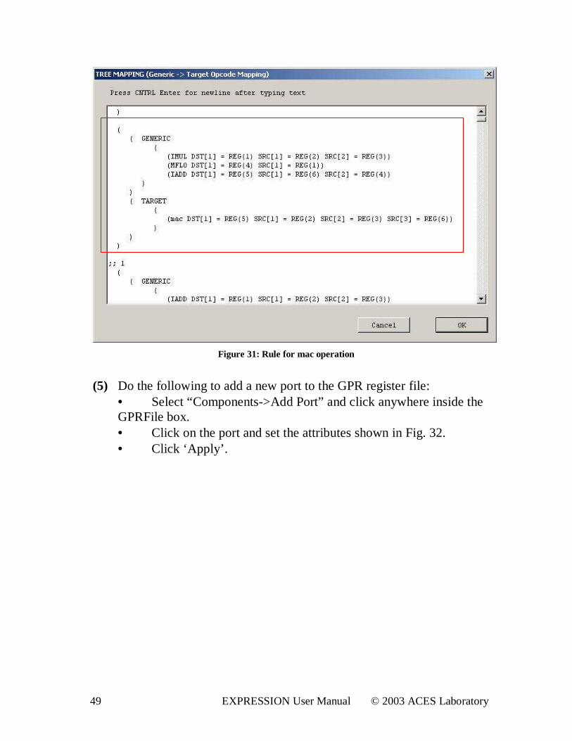
(4) Select “ set TREE_MAPPING” option from the “ Instruction Set” menu and add the rule for mac operation as shown in Fig. 31. Make sure the rule appears before the rules for IMUL, MFLO and IADD.
48 EXPRESSION User Manual © 2003 ACES Laboratory
Figure 30: mac operation
49 EXPRESSION User Manual © 2003 ACES Laboratory
Figure 31: Rule for mac operation
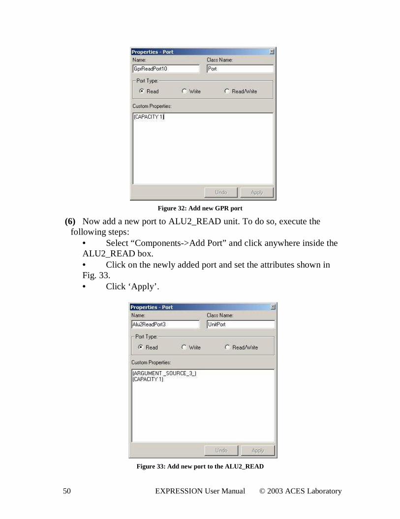
(5) Do the following to add a new port to the GPR register file:
• Select “Components->Add Port” and click anywhere inside the GPRFile box. • Click on the port and set the attributes shown in Fig. 32. • Click ‘Apply’ .
50 EXPRESSION User Manual © 2003 ACES Laboratory
Figure 32: Add new GPR por t
(6) Now add a new port to ALU2_READ unit. To do so, execute the following steps:
• Select “Components->Add Port” and click anywhere inside the ALU2_READ box. • Click on the newly added port and set the attributes shown in Fig. 33. • Click ‘Apply’ .
Figure 33: Add new por t to the ALU2_READ
51 EXPRESSION User Manual © 2003 ACES Laboratory
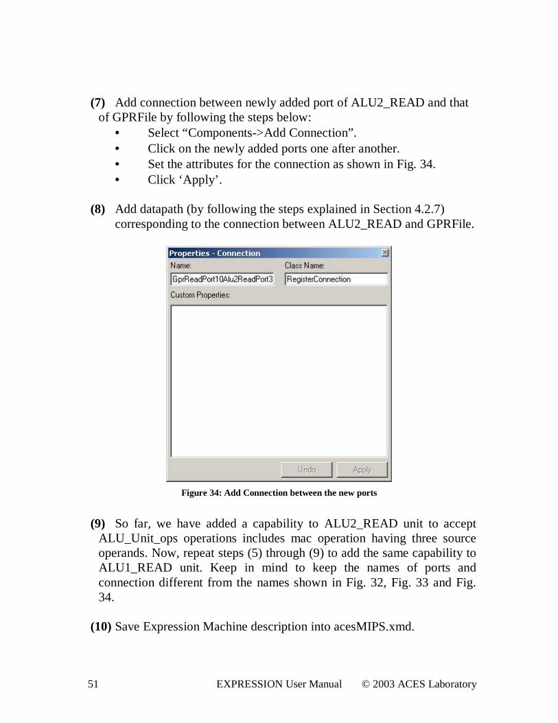
(7) Add connection between newly added port of ALU2_READ and that
of GPRFile by following the steps below: • Select “Components->Add Connection” . • Click on the newly added ports one after another. • Set the attributes for the connection as shown in Fig. 34. • Click ‘Apply’ .
(8) Add datapath (by following the steps explained in Section 4.2.7) corresponding to the connection between ALU2_READ and GPRFile.
Figure 34: Add Connection between the new por ts
(9) So far, we have added a capability to ALU2_READ unit to accept
ALU_Unit_ops operations includes mac operation having three source operands. Now, repeat steps (5) through (9) to add the same capability to ALU1_READ unit. Keep in mind to keep the names of ports and connection different from the names shown in Fig. 32, Fig. 33 and Fig. 34.
(10) Save Expression Machine description into acesMIPS.xmd.
52 EXPRESSION User Manual © 2003 ACES Laboratory
(11) Repeat the steps described in Section 2.3 to evaluate the modified architecture.
Expected result: You should be able to notice that the generated code contains mac instruction instead of a chain of mult, mflo and addu instructions. This will lead to an increase in performance because of reduction in the number of fetches. 5.1.2. Changing Register Accessibility Individual operands of each operation are mapped to particular register classes. These register classes effectively partition the register file and have a unique mapping to a particular set of registers. There is a fixed set of generic register classes expressed as class types and data types. Target register classes are specified by invoking “ set VAR_GROUP” from the “ Instruction Set” menu. Each target register class has a unique mapping to a set of target registers. The mappings of the generic register classes to the target register classes are specified by selecting “ set OPERAND_MAPPING”. The register accessibilities of the operands of operations are changed from “set OP_GROUPS” option in the “ Instruction Set” menu. In acesMIPS architecture, the target register class for the destination of mult operation is int_hilo, which maps to any of the registers in GPRFile[1-28]. Let us modify the register accessibility of the destination operand of mult and source operands of mfhi and mflo. Suppose, we want these operands to access only the odd-numbered registers in GPRFile[1-29]. We perform the following steps:
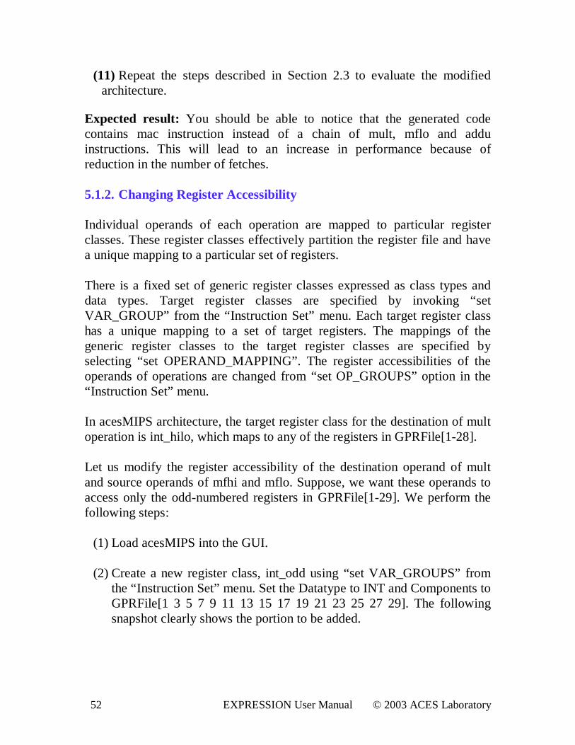
(1) Load acesMIPS into the GUI. (2) Create a new register class, int_odd using “set VAR_GROUPS” from
the “ Instruction Set” menu. Set the Datatype to INT and Components to GPRFile[1 3 5 7 9 11 13 15 17 19 21 23 25 27 29]. The following snapshot clearly shows the portion to be added.
53 EXPRESSION User Manual © 2003 ACES Laboratory
Figure 35: New register class, int_odd
Press ‘+’ to add to the list and click OK.
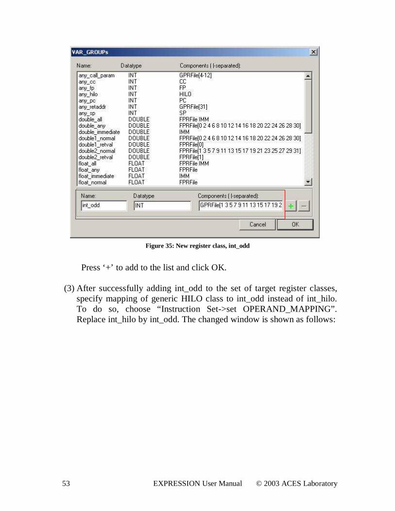
(3) After successfully adding int_odd to the set of target register classes,
specify mapping of generic HILO class to int_odd instead of int_hilo. To do so, choose “ Instruction Set->set OPERAND_MAPPING”. Replace int_hilo by int_odd. The changed window is shown as follows:
54 EXPRESSION User Manual © 2003 ACES Laboratory
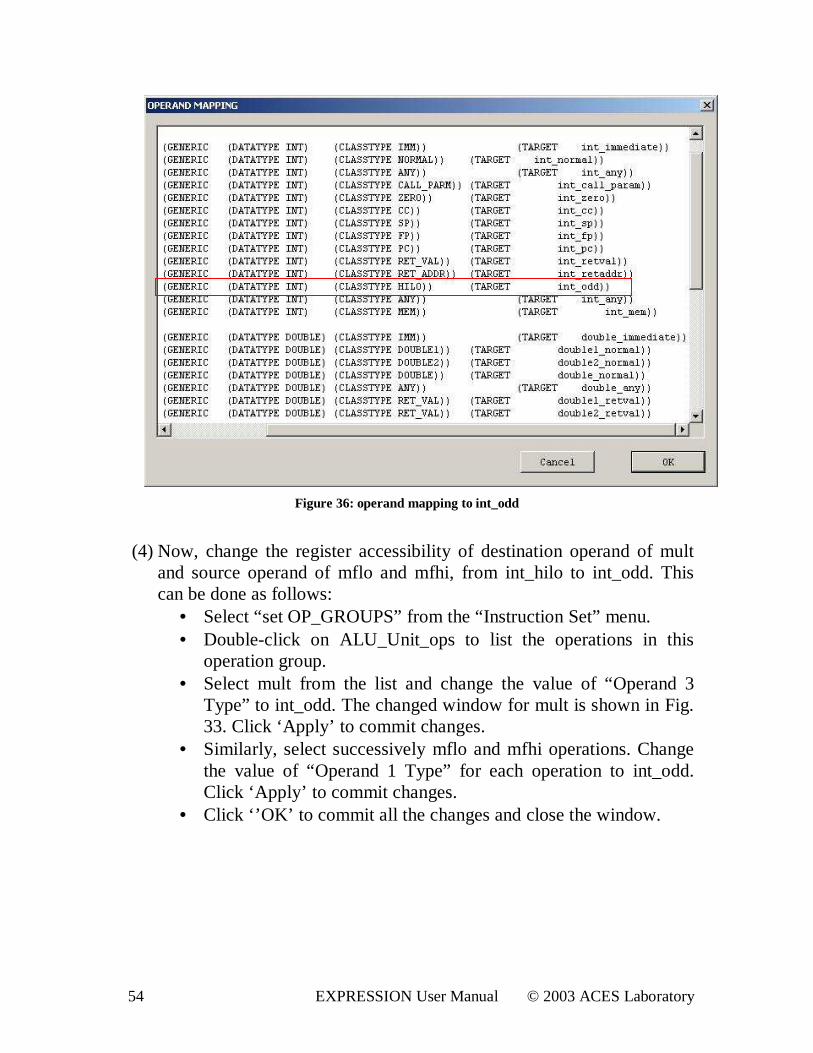
Figure 36: operand mapping to int_odd
(4) Now, change the register accessibility of destination operand of mult
and source operand of mflo and mfhi, from int_hilo to int_odd. This can be done as follows:
• Select “ set OP_GROUPS” from the “ Instruction Set” menu. • Double-click on ALU_Unit_ops to list the operations in this
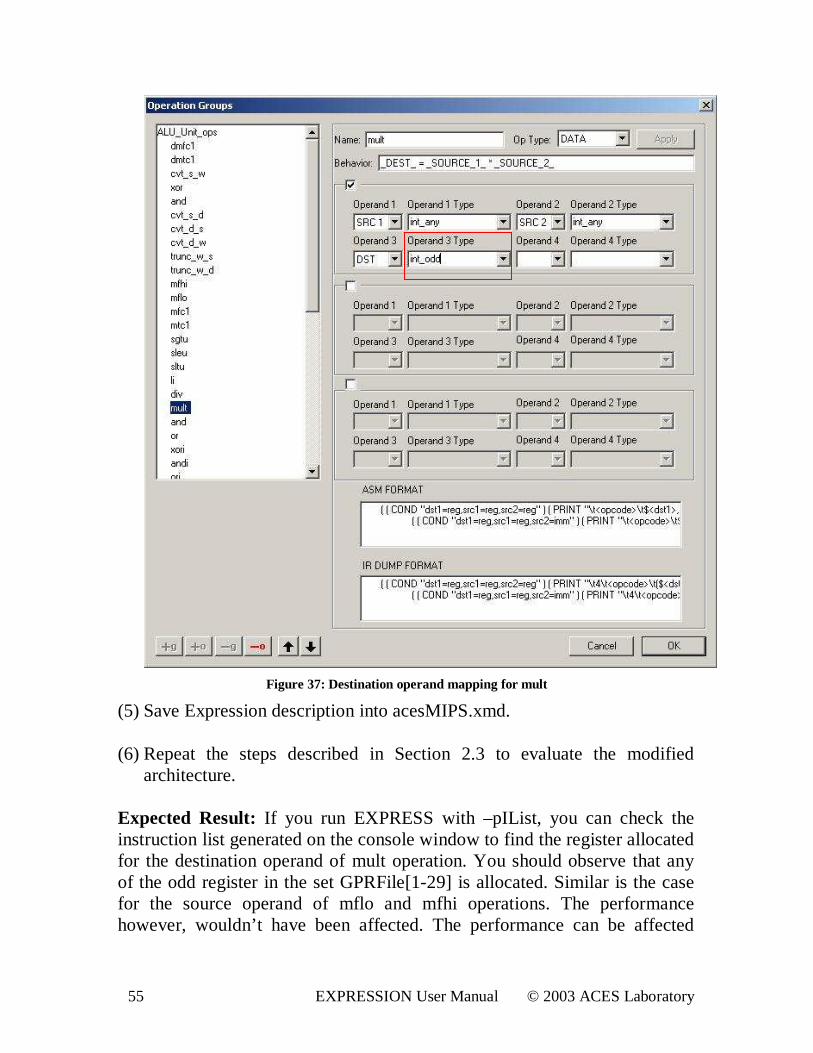
operation group. • Select mult from the list and change the value of “Operand 3
Type” to int_odd. The changed window for mult is shown in Fig. 33. Click ‘Apply’ to commit changes.
• Similarly, select successively mflo and mfhi operations. Change the value of “Operand 1 Type” for each operation to int_odd. Click ‘Apply’ to commit changes.
• Click ‘ ’OK’ to commit all the changes and close the window.
55 EXPRESSION User Manual © 2003 ACES Laboratory
Figure 37: Destination operand mapping for mult
(5) Save Expression description into acesMIPS.xmd. (6) Repeat the steps described in Section 2.3 to evaluate the modified
architecture. Expected Result: If you run EXPRESS with –pIList, you can check the instruction list generated on the console window to find the register allocated for the destination operand of mult operation. You should observe that any of the odd register in the set GPRFile[1-29] is allocated. Similar is the case for the source operand of mflo and mfhi operations. The performance however, wouldn’ t have been affected. The performance can be affected
56 EXPRESSION User Manual © 2003 ACES Laboratory
adversely by reducing the register accessibility of the operations to an extent that results in spilling of registers. 5.2. Pipeline Exploration An architecture can be modified by changing its pipeline. The pipeline changes can be made by just adding a new functional unit and have a new pipeline path go through the functional unit. The number of existing pipeline paths can also be reduced by deleting the resources. 5.2.1. Adding a Single-cycle/M ulti-cycle Functional unit A new functional unit can be added as a single-cycle, multi-cycle or a pipelined unit. An OP_GROUP containing multi-cycle operations is linked with a multi-cycle functional unit. The general process to create a new multi-cycle unit as a parallel resource requires the following steps:
i. Add new “Read” unit and “Execute” units by using ‘add Unit’ (Fig. 22). Add a latch (Fig. 24) to the Read unit and ‘add Connection’ (Fig. 25) from the Read Unit latch to Execute Unit.
ii. Add new port to the register file and also to the “Read” unit and establish a connection between the ports. Make sure that you specify the proper class names for all of the components (ports/latches/units) that you add.
iii. Create a new OP_GROUP (‘+g’ ) and add the multi-cycle operation (‘+o’ ) to the operation group. (Refer to Fig. 15)
iv. Link the newly created OP_GROUP with both “Read” and “Execute” units. (‘Supported opcodes’ in the unit properties must contain this OP_GROUP.)
v. In the timing section of the units, specify appropriate number of cycles along with the opcode. For example, If a multiplier takes two cycles, the corresponding “Read” and “execute” units will have ‘ (mult 2)’ specified in the timing section.
vi. Increase the capacity of the connection by one from WriteBack unit to RegisterFile.
Adding a new functional unit as a parallel resource is potentially equivalent to adding a new pipeline path.
57 EXPRESSION User Manual © 2003 ACES Laboratory
In the base architecture, both ALU1 and ALU2 support the same set of single-cycle operations. As an example, let’ s modify the base architecture to allow a two cycle multiply (mult) operation on ALU2 and rest of the operations (which are all single-cycle operations) on ALU1. To accomplish this, execute in sequence the following steps:
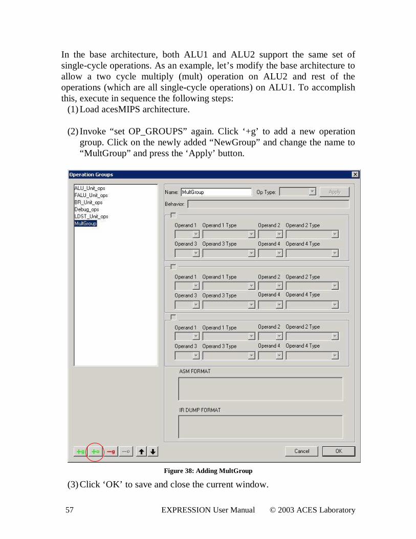
(1) Load acesMIPS architecture. (2) Invoke “ set OP_GROUPS” again. Click ‘+g’ to add a new operation
group. Click on the newly added “NewGroup” and change the name to “MultGroup” and press the ‘Apply’ button.
Figure 38: Adding MultGroup
(3) Click ‘OK’ to save and close the current window.
58 EXPRESSION User Manual © 2003 ACES Laboratory
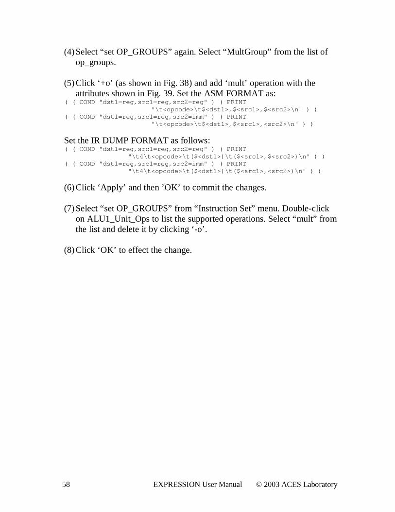
(4) Select “ set OP_GROUPS” again. Select “MultGroup” from the list of op_groups.
(5) Click ‘+o’ (as shown in Fig. 38) and add ‘mult’ operation with the
attributes shown in Fig. 39. Set the ASM FORMAT as: ( ( COND " dst 1=r eg, sr c1=r eg, sr c2=r eg" ) ( PRI NT
" \ t <opcode>\ t $<dst 1>, $<sr c1>, $<sr c2>\ n" ) ) ( ( COND " dst 1=r eg, sr c1=r eg, sr c2=i mm" ) ( PRI NT
" \ t <opcode>\ t $<dst 1>, $<sr c1>, <sr c2>\ n" ) )
Set the IR DUMP FORMAT as follows: ( ( COND " dst 1=r eg, sr c1=r eg, sr c2=r eg" ) ( PRI NT
" \ t 4\ t <opcode>\ t ( $<dst 1>) \ t ( $<sr c1>, $<sr c2>) \ n" ) ) ( ( COND " dst 1=r eg, sr c1=r eg, sr c2=i mm" ) ( PRI NT
" \ t 4\ t <opcode>\ t ( $<dst 1>) \ t ( $<sr c1>, <sr c2>) \ n" ) )
(6) Click ‘Apply’ and then ’OK’ to commit the changes. (7) Select “ set OP_GROUPS” from “ Instruction Set” menu. Double-click
on ALU1_Unit_Ops to list the supported operations. Select “ mult” from the list and delete it by clicking ‘ -o’ .
(8) Click ‘OK’ to effect the change.
59 EXPRESSION User Manual © 2003 ACES Laboratory
Figure 39: Add 'mult' operation
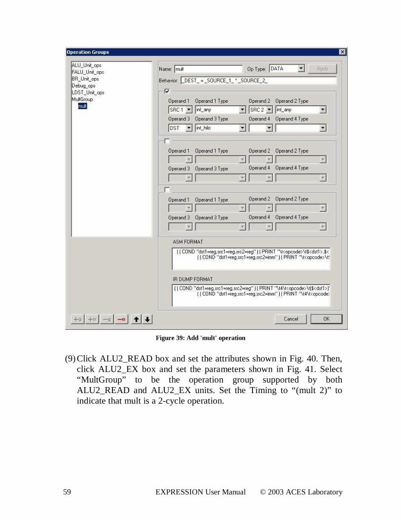
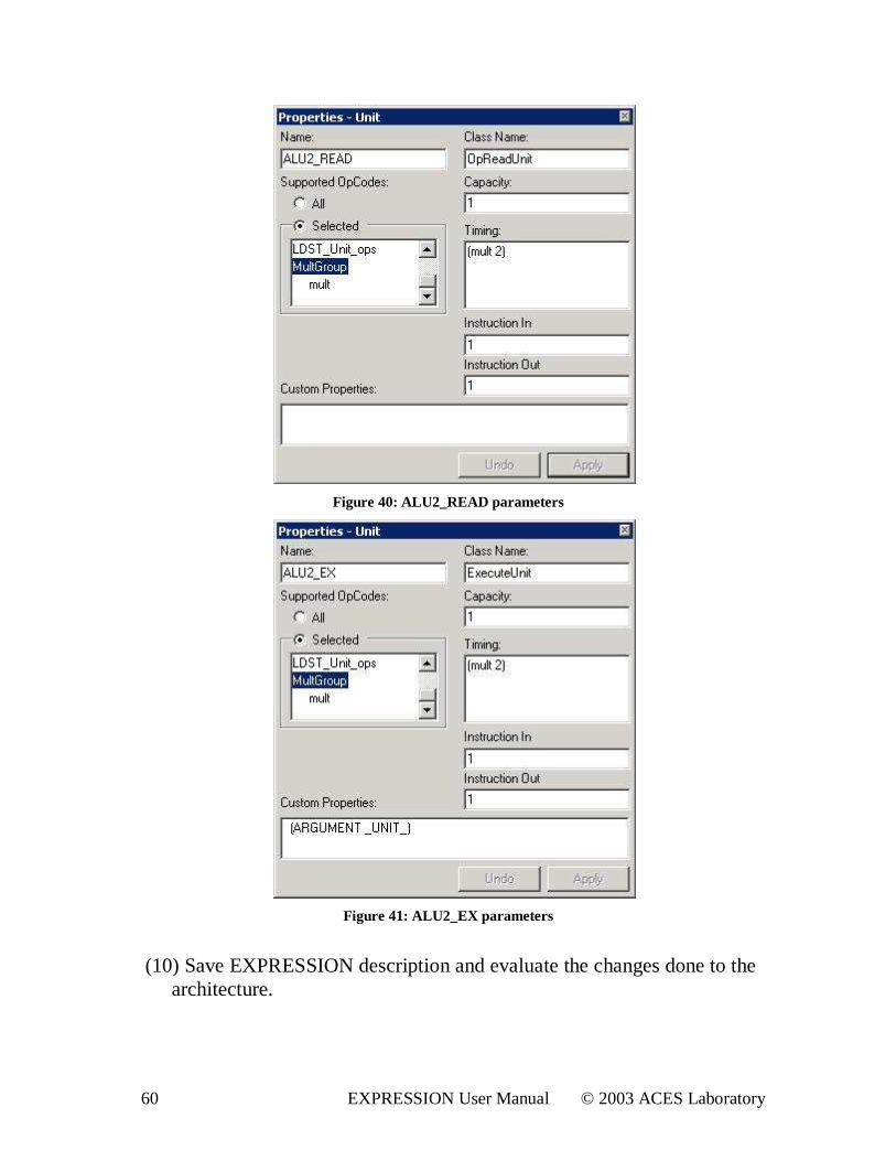
(9) Click ALU2_READ box and set the attributes shown in Fig. 40. Then, click ALU2_EX box and set the parameters shown in Fig. 41. Select “MultGroup” to be the operation group supported by both ALU2_READ and ALU2_EX units. Set the Timing to “ (mult 2)” to indicate that mult is a 2-cycle operation.
60 EXPRESSION User Manual © 2003 ACES Laboratory
Figure 40: ALU2_READ parameters
Figure 41: ALU2_EX parameters
(10) Save EXPRESSION description and evaluate the changes done to the
architecture.
61 EXPRESSION User Manual © 2003 ACES Laboratory
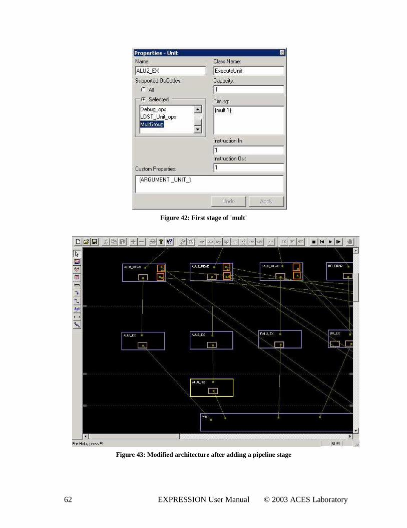
Expected Result: A degraded performance owing to increase in ‘ mult’ latency and decrease in the number of resources for all operations. 5.2.2. Adding a New Pipelined Functional Unit Adding a new pipeline path helps increase the parallelism in the datapath. The parallel resource can be a single-cycle/multi-cycle functional unit or a pipelined unit. A multi-cycle operation can be equivalently performed on a pipelined functional unit that will lead to an increase in the number of pipeline stages. Pipelining a multi-cycle operation should lead to increase in performance in cases where the multi-cycle operation is extensively used. A pipelined functional unit for operations running for n cycles is modeled by having one stage of class ExecuteUnit and (n-1) stages of class SimpleStageUnit in the pipeline path. As an illustration, let’ s convert the 2-cycle ‘ mult’ operation discussed in Section 5.2.1 into a two-stage pipelined operation. You need to perform following changes to the architecture obtained in Section 5.2.1:
(1) Click on ALU2_EX box and change the timing for “MultGroup” to ‘ (mult 1)’ . (as shown in Fig.)
62 EXPRESSION User Manual © 2003 ACES Laboratory
Figure 42: First stage of 'mult'
Figure 43: Modified architecture after adding a pipeline stage
63 EXPRESSION User Manual © 2003 ACES Laboratory
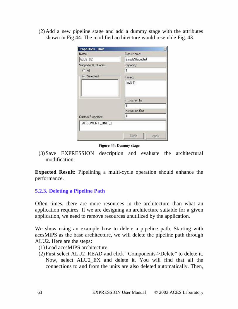
(2) Add a new pipeline stage and add a dummy stage with the attributes shown in Fig 44. The modified architecture would resemble Fig. 43.
Figure 44: Dummy stage
(3) Save EXPRESSION description and evaluate the architectural modification.
Expected Result: Pipelining a multi-cycle operation should enhance the performance. 5.2.3. Deleting a Pipeline Path Often times, there are more resources in the architecture than what an application requires. If we are designing an architecture suitable for a given application, we need to remove resources unutilized by the application. We show using an example how to delete a pipeline path. Starting with acesMIPS as the base architecture, we will delete the pipeline path through ALU2. Here are the steps:
(1) Load acesMIPS architecture. (2) First select ALU2_READ and click “Components->Delete” to delete it.
Now, select ALU2_EX and delete it. You will find that all the connections to and from the units are also deleted automatically. Then,
64 EXPRESSION User Manual © 2003 ACES Laboratory
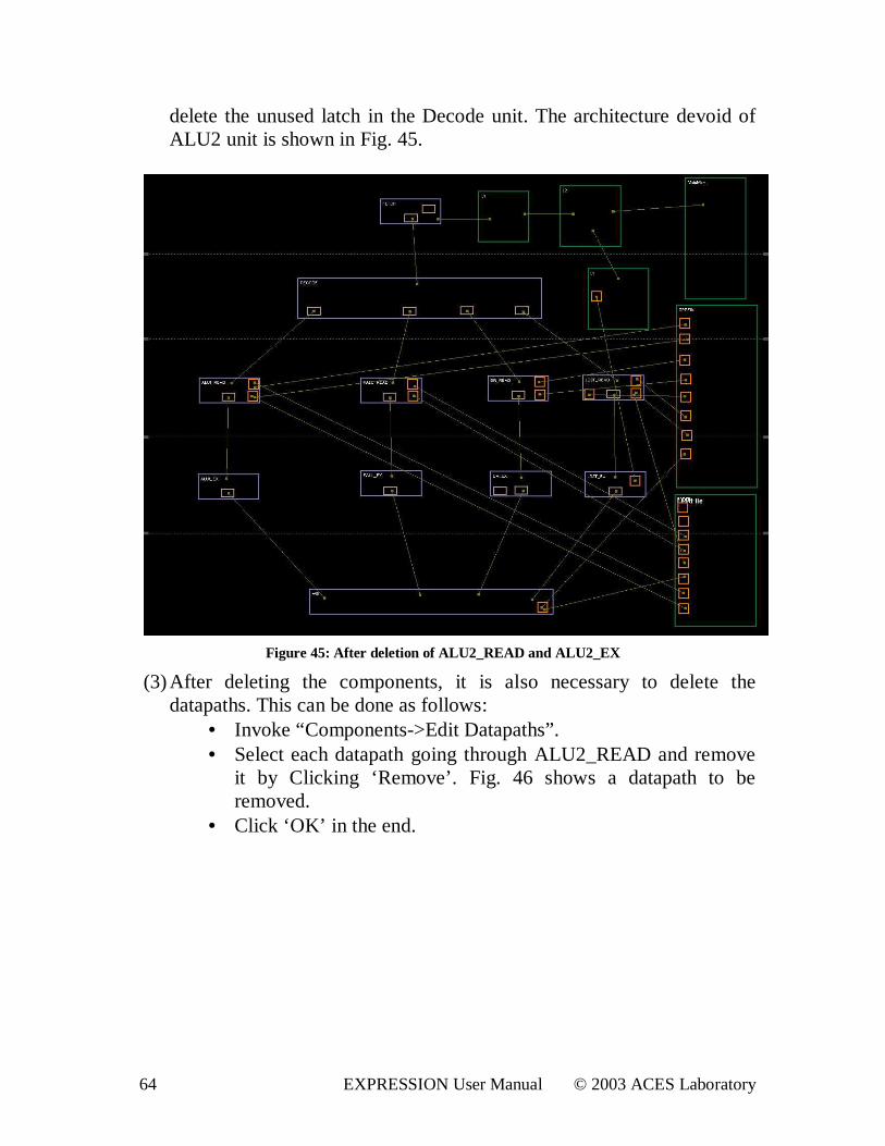
delete the unused latch in the Decode unit. The architecture devoid of ALU2 unit is shown in Fig. 45.
Figure 45: After deletion of ALU2_READ and ALU2_EX
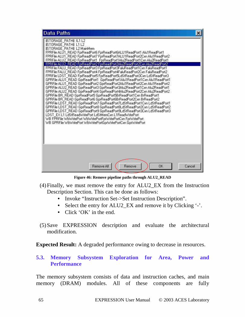
(3) After deleting the components, it is also necessary to delete the datapaths. This can be done as follows:
• Invoke “Components->Edit Datapaths” . • Select each datapath going through ALU2_READ and remove
it by Clicking ‘Remove’ . Fig. 46 shows a datapath to be removed.
• Click ‘OK’ in the end.
65 EXPRESSION User Manual © 2003 ACES Laboratory
Figure 46: Remove pipeline paths through ALU2_READ
(4) Finally, we must remove the entry for ALU2_EX from the Instruction Description Section. This can be done as follows:
• Invoke “ Instruction Set->Set Instruction Description” . • Select the entry for ALU2_EX and remove it by Clicking ‘ -’ . • Click ‘OK’ in the end.
(5) Save EXPRESSION description and evaluate the architectural
modification.
Expected Result: A degraded performance owing to decrease in resources. 5.3. Memory Subsystem Exploration for Area, Power and
Per formance The memory subsystem consists of data and instruction caches, and main memory (DRAM) modules. All of these components are fully
66 EXPRESSION User Manual © 2003 ACES Laboratory
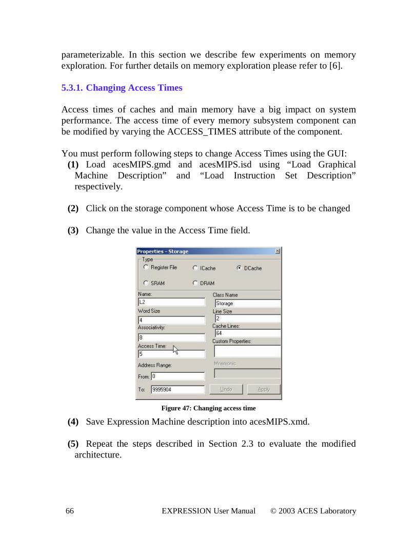
parameterizable. In this section we describe few experiments on memory exploration. For further details on memory exploration please refer to [6]. 5.3.1. Changing Access Times Access times of caches and main memory have a big impact on system performance. The access time of every memory subsystem component can be modified by varying the ACCESS_TIMES attribute of the component. You must perform following steps to change Access Times using the GUI:
(1) Load acesMIPS.gmd and acesMIPS.isd using “ Load Graphical Machine Description” and “Load Instruction Set Description” respectively.
(2) Click on the storage component whose Access Time is to be changed
(3) Change the value in the Access Time field.
Figure 47: Changing access time
(4) Save Expression Machine description into acesMIPS.xmd. (5) Repeat the steps described in Section 2.3 to evaluate the modified
architecture.
67 EXPRESSION User Manual © 2003 ACES Laboratory
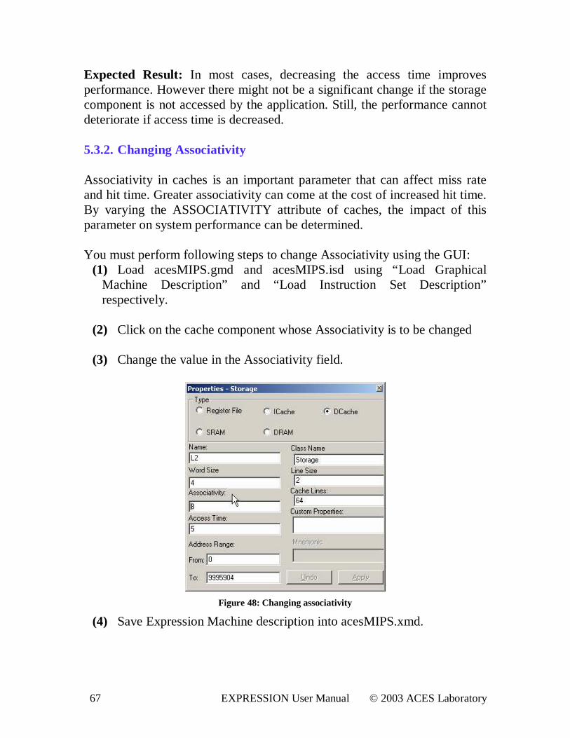
Expected Result: In most cases, decreasing the access time improves performance. However there might not be a significant change if the storage component is not accessed by the application. Still, the performance cannot deteriorate if access time is decreased. 5.3.2. Changing Associativity Associativity in caches is an important parameter that can affect miss rate and hit time. Greater associativity can come at the cost of increased hit time. By varying the ASSOCIATIVITY attribute of caches, the impact of this parameter on system performance can be determined. You must perform following steps to change Associativity using the GUI:
(1) Load acesMIPS.gmd and acesMIPS.isd using “ Load Graphical Machine Description” and “Load Instruction Set Description” respectively.
(2) Click on the cache component whose Associativity is to be changed
(3) Change the value in the Associativity field.
Figure 48: Changing associativity
(4) Save Expression Machine description into acesMIPS.xmd.
68 EXPRESSION User Manual © 2003 ACES Laboratory
(5) Repeat the steps described in Section 2.3 to evaluate the modified architecture.
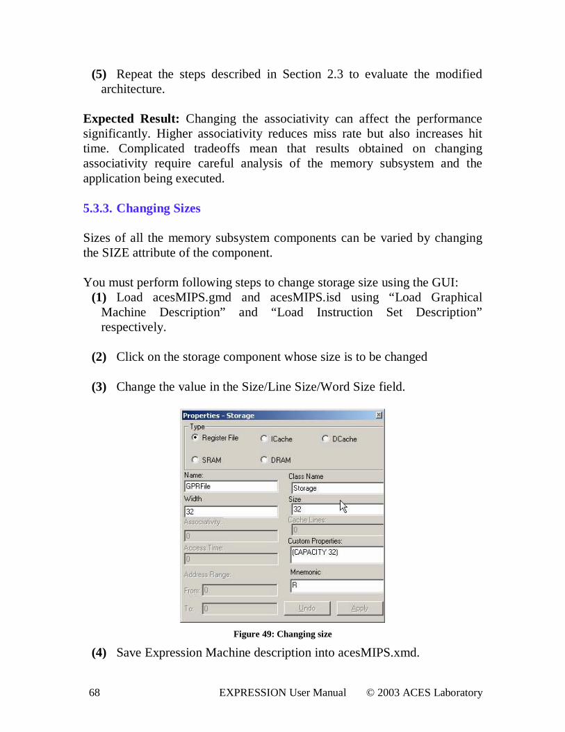
Expected Result: Changing the associativity can affect the performance significantly. Higher associativity reduces miss rate but also increases hit time. Complicated tradeoffs mean that results obtained on changing associativity require careful analysis of the memory subsystem and the application being executed. 5.3.3. Changing Sizes Sizes of all the memory subsystem components can be varied by changing the SIZE attribute of the component. You must perform following steps to change storage size using the GUI:
(1) Load acesMIPS.gmd and acesMIPS.isd using “ Load Graphical Machine Description” and “Load Instruction Set Description” respectively.
(2) Click on the storage component whose size is to be changed
(3) Change the value in the Size/Line Size/Word Size field.
Figure 49: Changing size
(4) Save Expression Machine description into acesMIPS.xmd.
69 EXPRESSION User Manual © 2003 ACES Laboratory
(5) Repeat the steps described in Section 2.3 to evaluate the modified architecture.
Expected Result: Increasing storage component size may not improve the performance if the majority of the data used by the application program fits in lower size. Power should definitely vary with size. However, power also depends on number of read/writes. Hence, increasing size may not increase power drastically, if number of read/writes remains same. Careful analysis of tradeoffs needs to be done to understand performance figures obtained by changing storage sizes. 5.3.4. Adding/Deleting Memory Modules It is possible to add new memory modules, for example an L3 cache between the L2 cache and the main memory module. It is also possible to delete any of the existing modules, for example the L2 cache, connecting the L1 caches directly to main memory. Let us enumerate the steps for deleting the L2 cache using the GUI:
(1) Load acesMIPS.gmd and acesMIPS.isd using “ Load Graphical Machine Description” and “Load Instruction Set Description” respectively.
(2) Click on the L2 cache and press ‘DELETE’ . This removes the cache
as well as all of its connections.
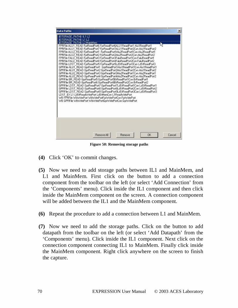
(3) From the ‘Components’ menu select ‘Edit datapaths’ . Click on the three storage paths, which have a reference to L2 to select them and then click on ‘Remove’ repeatedly till all three of the references are deleted.
70 EXPRESSION User Manual © 2003 ACES Laboratory
Figure 50: Removing storage paths
(4) Click ‘OK’ to commit changes. (5) Now we need to add storage paths between IL1 and MainMem, and
L1 and MainMem. First click on the button to add a connection component from the toolbar on the left (or select ‘ Add Connection’ from the ‘Components’ menu). Click inside the IL1 component and then click inside the MainMem component on the screen. A connection component will be added between the IL1 and the MainMem component.
(6) Repeat the procedure to add a connection between L1 and MainMem.
(7) Now we need to add the storage paths. Click on the button to add
datapath from the toolbar on the left (or select ‘ Add Datapath’ from the ‘Components’ menu). Click inside the IL1 component. Next click on the connection component connecting IL1 to MainMem. Finally click inside the MainMem component. Right click anywhere on the screen to finish the capture.
71 EXPRESSION User Manual © 2003 ACES Laboratory
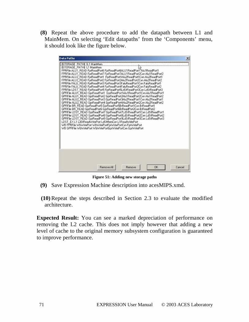
(8) Repeat the above procedure to add the datapath between L1 and MainMem. On selecting ‘ Edit datapaths’ from the ‘Components’ menu, it should look like the figure below.
Figure 51: Adding new storage paths
(9) Save Expression Machine description into acesMIPS.xmd.
(10) Repeat the steps described in Section 2.3 to evaluate the modified architecture.
Expected Result: You can see a marked depreciation of performance on removing the L2 cache. This does not imply however that adding a new level of cache to the original memory subsystem configuration is guaranteed to improve performance.
72 EXPRESSION User Manual © 2003 ACES Laboratory
6. Benchmarks The benchmarks that can be used for testing the EXPRESSION framework comprise the following:
• Livermore Loops. (Benchmarks/LLs) • Multimedia kernels. (Benchmarks/MMs)
For each benchmark, the IR dump is generated by EXPRESS and SIMPRESS gives the number of cycles of running the generated code on acesMIPS architecture. For <filename>.c, the generated IR dump is stored in <filename>_DUMP_IR_AFTER_REGALLOC.txt.
73 EXPRESSION User Manual © 2003 ACES Laboratory
7. Open Issues and Future Directions This is the first release of EXPRESSION and there are some limitations in the usage of the tool-set. We enumerate the limitations observed so far as follows:
• In this release, the applications having function calls are not supported.
• Compilation steps exist as three passes: PcProGUI, Expression console, acesMIPS console.
• A complex instruction supported in the target architecture must be composed of generic instructions having same types.
• The compiler is not aware of the presence of the memory hierarchy. But, the simulator is.
• The register file is partitioned to the extent there is partition in the generic machine.
74 EXPRESSION User Manual © 2003 ACES Laboratory
8. References [1] A. Khare, N. Savoiu, A. Halambi, P. Grun, N. Dutt and A. Nicolau. V-SAT: A visual specification and analysis tool for system-on-chip exploration. Proc. EUROMICRO, 1999. [2] P. Grun, A. Halambi, A. Khare, V. Ganesh, N. Dutt and A. Nicolau. EXPRESSION: An ADL for System Level Design Exploration. ICS Technical Report # 98-29, University of California, Irvine, September 1999. [3] P. Grun, A. Halambi, N. Dutt and A. Nicolau. RTGEN: An algorithm for automatic generation of reservation tables from architectural descriptions. ISSS, San Jose, CA, 1999. [4] A. Nicolau and S. Novack. Trailblazing: A hierarchical approach to percolation scheduling. ICPP, St. Charles, IL, 1993. [5] P. Mishra, P. Grun, N. Dutt, A. Nicolau. Memory Subsystem Description in EXPRESSION. ICS Technical Report # 00-31, University of California, Irvine, October 2000. [6] P. Mishra, M. Mamidipaka, N. Dutt. A Framework for Memory Subsystem Exploration. CECS Technical Report # 01-20, University of California Irvine, May 2001. [7] P. Mishra, F. Rousseau, N. Dutt, and A. Nicolau. Architecture Description Language driven Design Space Exploration in the Presence of CoProcessors. SASIMI, October 2001. [8] P. Mishra, P. Grun, N. Dutt, and A. Nicolau. Processor-Memory Co Exploration driven by a Memory-Aware Architecture Description Language. VLSI Design, January 2001. [9] P. Mishra, N. Dutt, and A. Nicolau. Functional Abstraction driven Design Space Exploration of Heterogeneous Programmable Architectures. ISSS, October 2001. [10] S. Pasricha, P. Biswas, P. Mishra, A. Shrivastava, A. Mandal, N. Dutt, A. Nicolau, A Framework for GUI-driven Design Space Exploration of a MIPS4K-like Processor, CECS Technical Report 03-17, April, 2003
75 EXPRESSION User Manual © 2003 ACES Laboratory
Appendix A: EXPRESSION ADL EXPRESSION employs a simple LISP-like syntax to ease specification and enhance readability. An EXPRESSION description is composed of two main sections: Behavior (or IS) and Structure. The Behavior section is further sub-divided into Operations, Instruction and Operation Mappings sections. The Structure section is sub-divided into Components, Pipeline/Data Transfer Paths and Memory Subsystem sections. A.1. Operations This subsection describes the IS of the processor. The IS is organized into operation groups, with each group containing a set of operations having some common characteristics. Each operation is then described in terms of its opcode, operands and behavior. Each operand is classified either as source or as destination. Further, each operand has an associated list of register files to which it can be bound. These lists are specified in the VAR GROUPS subsection. A.2. Instruction This subsection captures the parallelism available in the architecture. An Instruction is viewed as containing operations that can be executed in parallel. Each Instruction contains a list of slots (to be filled with operations), with each slot corresponding to a Functional Unit. A.3. Operation Mappings In this subsection the user specifies information needed by Instruction Selection and architecture specific optimizations of the compiler. Each entry in this subsection represents the mapping of a (sequence of) operation to another (sequence of) operations. The mapping can be from generic compiler operations to target processor operations, in which case it is used by the instruction selection algorithm, or from target operations to target operations, to be used as architecture dependent optimizations. The instruction selection algorithm uses a tree parsing technique utilizing dynamic programming.
76 EXPRESSION User Manual © 2003 ACES Laboratory
A.4. Components This subsection describes each RT level component in the architecture. The components can be any of Pipeline units, Functional units, Storage elements, Ports and Connections. Each component also has a list of attributes (optional). The attributes can be any of the following: SUBCOMPONENTS: If the component is a compound component, specifies the list of subcomponents. LATCHES: If the component is a unit, specifies the list of latches that the unit is attached to. PORTS: The list of ports attached to this component. CONNECTIONS: The list of connections attached to this component. OPCODES: The list of opcode groups that this component accepts. (Note: If this attribute is all then it means that the component does not make a distinction between opcodes.) TIMING: For multi cycle or pipelined units, specifies the timing behavior. Timing can be specified on a per opcode basis if necessary. CAPACITY: The number of operations that can be accepted by this component in a single cycle. The default is a single operation per cycle. A.5. Pipeline and Data Transfer Paths This subsection describes the net-list of the processor. The pipeline description provides a mechanism to specify the units that comprise the pipeline stages, while the data-transfer paths description provides a mechanism for specifying the valid data-transfers. This information is used to both retarget the simulator, and to generate reservation tables needed by the scheduler. The pipeline paths and the data transfers represent the structural net-list information for the architecture. They can be generated automatically from a schematic capture tool. When writing/generating this information, false paths may be present in the architecture. This problem is solved by the fact that besides the net-list, behavioral information is also present. False paths due to illegal operations will never be activated, since the illegal operations are omitted from the description. False paths due to illegal groups of operations (either in sequence or in parallel) can be tackled by either specifying the common resource used by the operations to raise a conflict in
77 EXPRESSION User Manual © 2003 ACES Laboratory
the reservation tables, or by explicitly specifying the group of operations as illegal. A.6. Memory Subsystem This subsection describes the properties of the components in the memory subsystem that are required by the memory-aware compiler optimizations. In EXPRESSION, the net-list specification provides the connectivity between the various storage component and units. The attributes of each storage component (that are useful for the memory-aware compiler optimizations) are specified in this section. EXPRESSION can be used to describe diverse traditional and non-traditional memory systems. Non-traditional memory systems differ from the conventional, simple memory hierarchies in several ways. First, the complex organization of the components in these systems may result in a partitioned address space. The partitioned address space is captured using the ADDRESS RANGE parameter associated with the relevant memory units. The ACCESS TIMES parameter captures the latency information for individual memory components in the architecture. The latency associated with any level of the memory hierarchy can be easily computed using the hierarchy information (from the net-list) and the ACCESS TIMES attribute of each component. Second, they may contain novel components (e.g. SDRAM, Frame buffer, Stream buffer, etc). These components may allow for varying access times depending on the mode of access. The user can specify this feature as a list of access times in the ACCESS TIMES attribute of the component. The language provides certain pre-defined parameters (like TYPE, SIZE etc). The TYPE parameter is used to identify each storage component. EXPRESSION contains certain predefined types like REGFILE, DRAM, CACHE, SRAM etc. New types can be easily added as a user defined type. The user can also add new parameters in order to specify the features of novel components (for use by the compiler optimizations). Note that some parameters like the number and type of ports associated with each component are described in the Components Specification subsection. For details on memory subsystem description, please refer to [5]. The EXPRESSION ADL description of the acesMIPS is available in <wor k>\ acesMI PSDl l \ bi n\ Exampl e_acesMI PS. xmd.
78 EXPRESSION User Manual © 2003 ACES Laboratory
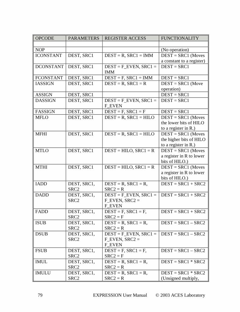
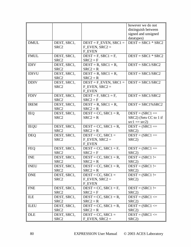
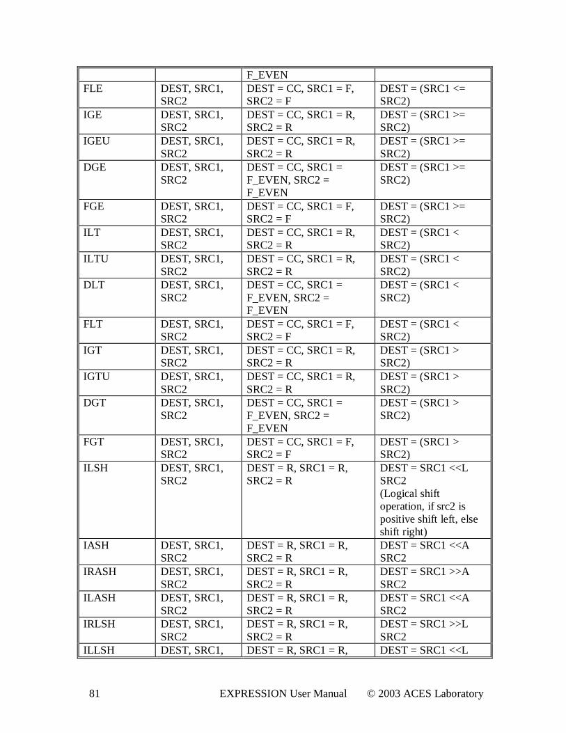
Appendix B: Gener ic Machine Model The front-end of the retargetable EXPRESS compiler translates the input application in “C” to generic instructions, and generic operands. The machine comprising of a generic instruction set is called “Generic Machine” . Instruction Selection and Register Allocation phases of the compiler transform the code from the generic to the instruction set of the target architecture. The phases of a retargetable compiler can be divided into two distinct phases, first the generic, machine independent compiler phases, and second the machine dependent compiler phases. The machine independent phases optimize the code for generic machine, and are applied for any target machine. The “Generic Machine” has a RISC ISA, very similar to MIPS ISA. The operations of “Generic Machine” , their functionality and the register accessibility of operands are explained in the table below. The “Generic Machine” has three data-types namely, Integer, Double, and Floats. It has 7 register files, R, F, CC, SP, FP, PC, HILO. R is the integer register file, and F is the floating-point register file. The pairs of F registers are used for Double data-types. The double operands are accessed by the “even numbered” registers. The second “odd numbered” register is an implicit operands in such operations. HILO is a special 64-bit register. The multiply operations write the result in this register. Later the results are extracted from this register file using the operations, MFLO and MFHI. The CC is a separate register file into which the evaluation results of conditionals are written. The register files, SP, PC and FP contain one register each, namely sp, pc and fp respectively. The following table presents the Instruction Set Architecture of the generic machine.
79 EXPRESSION User Manual © 2003 ACES Laboratory
OPCODE PARAMETERS REGISTER ACCESS FUNCTIONALITY NOP (No operation) ICONSTANT DEST, SRC1 DEST = R, SRC1 = IMM DEST = SRC1 (Moves
a constant to a register) DCONSTANT DEST, SRC1 DEST = F_EVEN, SRC1 =
IMM DEST = SRC1
FCONSTANT DEST, SRC1 DEST = F, SRC1 = IMM DEST = SRC1 IASSIGN DEST, SRC1 DEST = R, SRC1 = R DEST = SRC1 (Move
operation) ASSIGN DEST, SRC1 DEST = SRC1 DASSIGN DEST, SRC1 DEST = F_EVEN, SRC1 =
F_EVEN DEST = SRC1
FASSIGN DEST, SRC1 DEST = F, SRC1 = F DEST = SRC1 MFLO DEST, SRC1 DEST = R, SRC1 = HILO DEST = SRC1 (Moves
the lower bits of HILO to a register in R.)
MFHI DEST, SRC1 DEST = R, SRC1 = HILO DEST = SRC1 (Moves the higher bits of HILO to a register in R.)
MTLO DEST, SRC1 DEST = HILO, SRC1 = R DEST = SRC1 (Moves a register in R to lower bits of HILO.)
MTHI DEST, SRC1 DEST = HILO, SRC1 = R DEST = SRC1 (Moves a register in R to lower bits of HILO.)
IADD DEST, SRC1, SRC2
DEST = R, SRC1 = R, SRC2 = R
DEST = SRC1 + SRC2
DADD DEST, SRC1, SRC2
DEST = F_EVEN, SRC1 = F_EVEN, SRC2 = F_EVEN
DEST = SRC1 + SRC2
FADD DEST, SRC1, SRC2
DEST = F, SRC1 = F, SRC2 = F
DEST = SRC1 + SRC2
ISUB DEST, SRC1, SRC2
DEST = R, SRC1 = R, SRC2 = R
DEST = SRC1 – SRC2
DSUB DEST, SRC1, SRC2
DEST = F_EVEN, SRC1 = F_EVEN, SRC2 = F_EVEN
DEST = SRC1 – SRC2
FSUB DEST, SRC1, SRC2
DEST = F, SRC1 = F, SRC2 = F
DEST = SRC1 – SRC2
IMUL DEST, SRC1, SRC2
DEST = R, SRC1 = R, SRC2 = R
DEST = SRC1 * SRC2
IMULU DEST, SRC1, SRC2
DEST = R, SRC1 = R, SRC2 = R
DEST = SRC1 * SRC2 (Unsigned multiply,
80 EXPRESSION User Manual © 2003 ACES Laboratory
however we do not distinguish between signed and unsigned datatypes)
DMUL DEST, SRC1, SRC2
DEST = F_EVEN, SRC1 = F_EVEN, SRC2 = F_EVEN
DEST = SRC1 * SRC2
FMUL DEST, SRC1, SRC2
DEST = F, SRC1 = F, SRC2 = F
DEST = SRC1 * SRC2
IDIV DEST, SRC1, SRC2
DEST = R, SRC1 = R, SRC2 = R
DEST = SRC1/SRC2
IDIVU DEST, SRC1, SRC2
DEST = R, SRC1 = R, SRC2 = R
DEST = SRC1/SRC2
DDIV DEST, SRC1, SRC2
DEST = F_EVEN, SRC1 = F_EVEN, SRC2 = F_EVEN
DEST = SRC1/SRC2
FDIV DEST, SRC1, SRC2
DEST = F, SRC1 = F, SRC2 = F
DEST = SRC1/SRC2
IREM DEST, SRC1, SRC2
DEST = R, SRC1 = R, SRC2 = R
DEST = SRC1%SRC2
IEQ DEST, SRC1, SRC2
DEST = CC, SRC1 = R, SRC2 = R
DEST = (SRC1 == SRC2) (Sets CC to 1 if src1 == src2)
IEQU DEST, SRC1, SRC2
DEST = CC, SRC1 = R, SRC2 = R
DEST = (SRC1 == SRC2)
DEQ DEST, SRC1, SRC2
DEST = CC, SRC1 = F_EVEN, SRC2 = F_EVEN
DEST = (SRC1 == SRC2)
FEQ DEST, SRC1, SRC2
DEST = CC, SRC1 = F, SRC2 = F
DEST = (SRC1 == SRC2)
INE DEST, SRC1, SRC2
DEST = CC, SRC1 = R, SRC2 = R
DEST = (SRC1 != SRC2)
INEU DEST, SRC1, SRC2
DEST = CC, SRC1 = R, SRC2 = R
DEST = (SRC1 != SRC2)
DNE DEST, SRC1, SRC2
DEST = CC, SRC1 = F_EVEN, SRC2 = F_EVEN
DEST = (SRC1 != SRC2)
FNE DEST, SRC1, SRC2
DEST = CC, SRC1 = F, SRC2 = F
DEST = (SRC1 != SRC2)
ILE DEST, SRC1, SRC2
DEST = CC, SRC1 = R, SRC2 = R
DEST = (SRC1 <= SRC2)
ILEU DEST, SRC1, SRC2
DEST = CC, SRC1 = R, SRC2 = R
DEST = (SRC1 <= SRC2)
DLE DEST, SRC1, SRC2
DEST = CC, SRC1 = F_EVEN, SRC2 =
DEST = (SRC1 <= SRC2)
81 EXPRESSION User Manual © 2003 ACES Laboratory
F_EVEN FLE DEST, SRC1,
SRC2 DEST = CC, SRC1 = F, SRC2 = F
DEST = (SRC1 <= SRC2)
IGE DEST, SRC1, SRC2
DEST = CC, SRC1 = R, SRC2 = R
DEST = (SRC1 >= SRC2)
IGEU DEST, SRC1, SRC2
DEST = CC, SRC1 = R, SRC2 = R
DEST = (SRC1 >= SRC2)
DGE DEST, SRC1, SRC2
DEST = CC, SRC1 = F_EVEN, SRC2 = F_EVEN
DEST = (SRC1 >= SRC2)
FGE DEST, SRC1, SRC2
DEST = CC, SRC1 = F, SRC2 = F
DEST = (SRC1 >= SRC2)
ILT DEST, SRC1, SRC2
DEST = CC, SRC1 = R, SRC2 = R
DEST = (SRC1 < SRC2)
ILTU DEST, SRC1, SRC2
DEST = CC, SRC1 = R, SRC2 = R
DEST = (SRC1 < SRC2)
DLT DEST, SRC1, SRC2
DEST = CC, SRC1 = F_EVEN, SRC2 = F_EVEN
DEST = (SRC1 < SRC2)
FLT DEST, SRC1, SRC2
DEST = CC, SRC1 = F, SRC2 = F
DEST = (SRC1 < SRC2)
IGT DEST, SRC1, SRC2
DEST = CC, SRC1 = R, SRC2 = R
DEST = (SRC1 > SRC2)
IGTU DEST, SRC1, SRC2
DEST = CC, SRC1 = R, SRC2 = R
DEST = (SRC1 > SRC2)
DGT DEST, SRC1, SRC2
DEST = CC, SRC1 = F_EVEN, SRC2 = F_EVEN
DEST = (SRC1 > SRC2)
FGT DEST, SRC1, SRC2
DEST = CC, SRC1 = F, SRC2 = F
DEST = (SRC1 > SRC2)
ILSH DEST, SRC1, SRC2
DEST = R, SRC1 = R, SRC2 = R
DEST = SRC1 <<L SRC2 (Logical shift operation, if src2 is positive shift left, else shift right)
IASH DEST, SRC1, SRC2
DEST = R, SRC1 = R, SRC2 = R
DEST = SRC1 <<A SRC2
IRASH DEST, SRC1, SRC2
DEST = R, SRC1 = R, SRC2 = R
DEST = SRC1 >>A SRC2
ILASH DEST, SRC1, SRC2
DEST = R, SRC1 = R, SRC2 = R
DEST = SRC1 <<A SRC2
IRLSH DEST, SRC1, SRC2
DEST = R, SRC1 = R, SRC2 = R
DEST = SRC1 >>L SRC2
ILLSH DEST, SRC1, DEST = R, SRC1 = R, DEST = SRC1 <<L
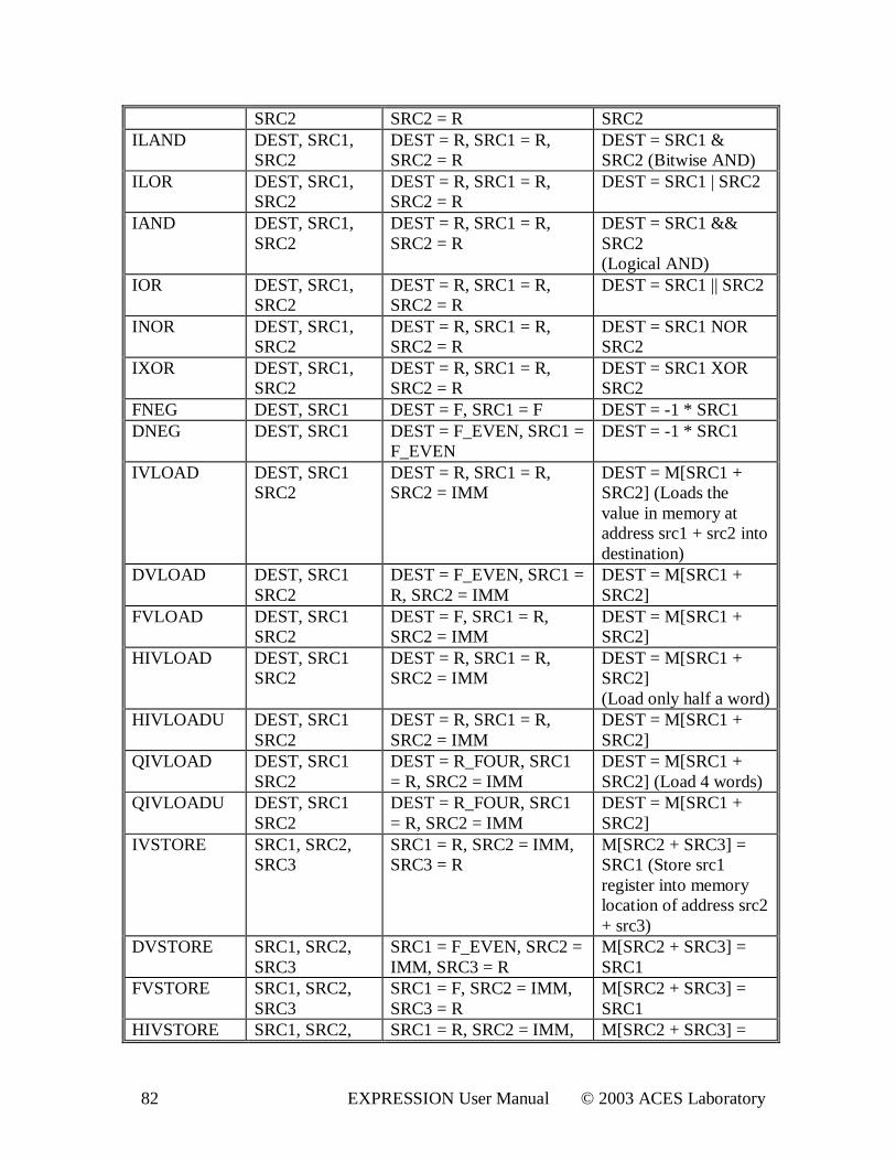
82 EXPRESSION User Manual © 2003 ACES Laboratory
SRC2 SRC2 = R SRC2 ILAND DEST, SRC1,
SRC2 DEST = R, SRC1 = R, SRC2 = R
DEST = SRC1 & SRC2 (Bitwise AND)
ILOR DEST, SRC1, SRC2
DEST = R, SRC1 = R, SRC2 = R
DEST = SRC1 | SRC2
IAND DEST, SRC1, SRC2
DEST = R, SRC1 = R, SRC2 = R
DEST = SRC1 && SRC2 (Logical AND)
IOR DEST, SRC1, SRC2
DEST = R, SRC1 = R, SRC2 = R
DEST = SRC1 || SRC2
INOR DEST, SRC1, SRC2
DEST = R, SRC1 = R, SRC2 = R
DEST = SRC1 NOR SRC2
IXOR DEST, SRC1, SRC2
DEST = R, SRC1 = R, SRC2 = R
DEST = SRC1 XOR SRC2
FNEG DEST, SRC1 DEST = F, SRC1 = F DEST = -1 * SRC1 DNEG DEST, SRC1 DEST = F_EVEN, SRC1 =
F_EVEN DEST = -1 * SRC1
IVLOAD DEST, SRC1 SRC2
DEST = R, SRC1 = R, SRC2 = IMM
DEST = M[SRC1 + SRC2] (Loads the value in memory at address src1 + src2 into destination)
DVLOAD DEST, SRC1 SRC2
DEST = F_EVEN, SRC1 = R, SRC2 = IMM
DEST = M[SRC1 + SRC2]
FVLOAD DEST, SRC1 SRC2
DEST = F, SRC1 = R, SRC2 = IMM
DEST = M[SRC1 + SRC2]
HIVLOAD DEST, SRC1 SRC2
DEST = R, SRC1 = R, SRC2 = IMM
DEST = M[SRC1 + SRC2] (Load only half a word)
HIVLOADU DEST, SRC1 SRC2
DEST = R, SRC1 = R, SRC2 = IMM
DEST = M[SRC1 + SRC2]
QIVLOAD DEST, SRC1 SRC2
DEST = R_FOUR, SRC1 = R, SRC2 = IMM
DEST = M[SRC1 + SRC2] (Load 4 words)
QIVLOADU DEST, SRC1 SRC2
DEST = R_FOUR, SRC1 = R, SRC2 = IMM
DEST = M[SRC1 + SRC2]
IVSTORE SRC1, SRC2, SRC3
SRC1 = R, SRC2 = IMM, SRC3 = R
M[SRC2 + SRC3] = SRC1 (Store src1 register into memory location of address src2 + src3)
DVSTORE SRC1, SRC2, SRC3
SRC1 = F_EVEN, SRC2 = IMM, SRC3 = R
M[SRC2 + SRC3] = SRC1
FVSTORE SRC1, SRC2, SRC3
SRC1 = F, SRC2 = IMM, SRC3 = R
M[SRC2 + SRC3] = SRC1
HIVSTORE SRC1, SRC2, SRC1 = R, SRC2 = IMM, M[SRC2 + SRC3] =
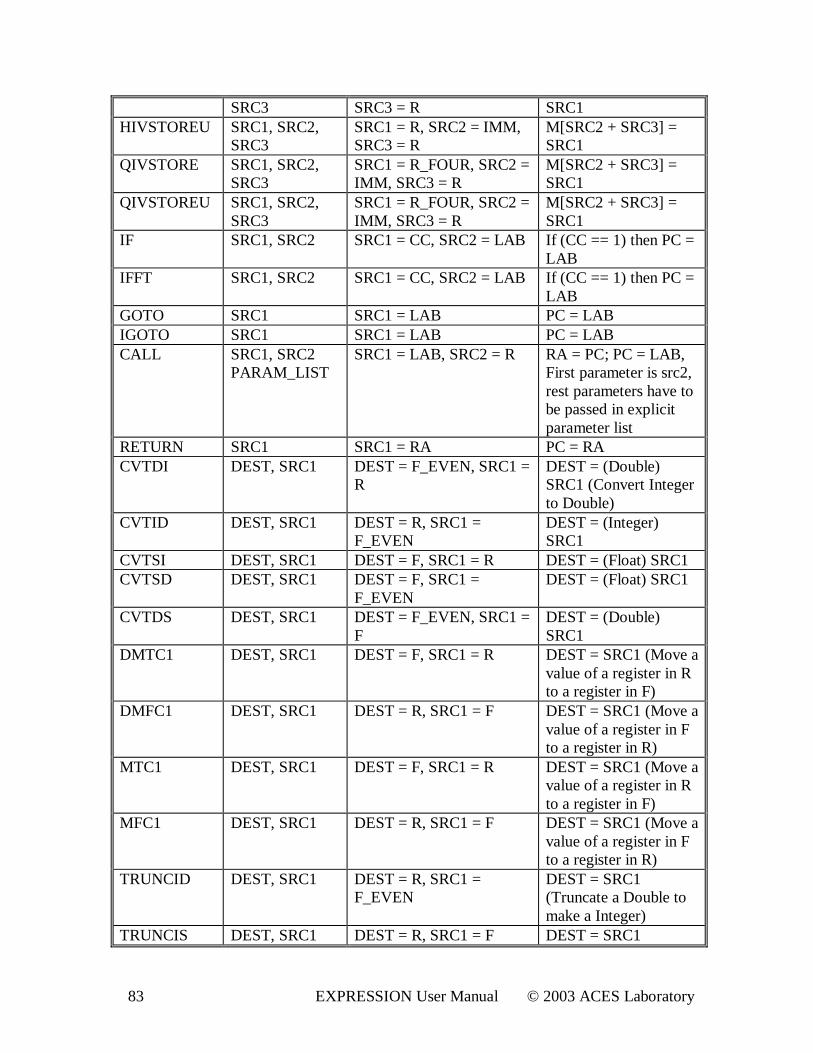
83 EXPRESSION User Manual © 2003 ACES Laboratory
SRC3 SRC3 = R SRC1 HIVSTOREU SRC1, SRC2,
SRC3 SRC1 = R, SRC2 = IMM, SRC3 = R
M[SRC2 + SRC3] = SRC1
QIVSTORE SRC1, SRC2, SRC3
SRC1 = R_FOUR, SRC2 = IMM, SRC3 = R
M[SRC2 + SRC3] = SRC1
QIVSTOREU SRC1, SRC2, SRC3
SRC1 = R_FOUR, SRC2 = IMM, SRC3 = R
M[SRC2 + SRC3] = SRC1
IF SRC1, SRC2 SRC1 = CC, SRC2 = LAB If (CC == 1) then PC = LAB
IFFT SRC1, SRC2 SRC1 = CC, SRC2 = LAB If (CC == 1) then PC = LAB
GOTO SRC1 SRC1 = LAB PC = LAB IGOTO SRC1 SRC1 = LAB PC = LAB CALL SRC1, SRC2
PARAM_LIST SRC1 = LAB, SRC2 = R RA = PC; PC = LAB,
First parameter is src2, rest parameters have to be passed in explicit parameter list
RETURN SRC1 SRC1 = RA PC = RA CVTDI DEST, SRC1 DEST = F_EVEN, SRC1 =
R DEST = (Double) SRC1 (Convert Integer to Double)
CVTID DEST, SRC1 DEST = R, SRC1 = F_EVEN
DEST = (Integer) SRC1
CVTSI DEST, SRC1 DEST = F, SRC1 = R DEST = (Float) SRC1 CVTSD DEST, SRC1 DEST = F, SRC1 =
F_EVEN DEST = (Float) SRC1
CVTDS DEST, SRC1 DEST = F_EVEN, SRC1 = F
DEST = (Double) SRC1
DMTC1 DEST, SRC1 DEST = F, SRC1 = R DEST = SRC1 (Move a value of a register in R to a register in F)
DMFC1 DEST, SRC1 DEST = R, SRC1 = F DEST = SRC1 (Move a value of a register in F to a register in R)
MTC1 DEST, SRC1 DEST = F, SRC1 = R DEST = SRC1 (Move a value of a register in R to a register in F)
MFC1 DEST, SRC1 DEST = R, SRC1 = F DEST = SRC1 (Move a value of a register in F to a register in R)
TRUNCID DEST, SRC1 DEST = R, SRC1 = F_EVEN
DEST = SRC1 (Truncate a Double to make a Integer)
TRUNCIS DEST, SRC1 DEST = R, SRC1 = F DEST = SRC1
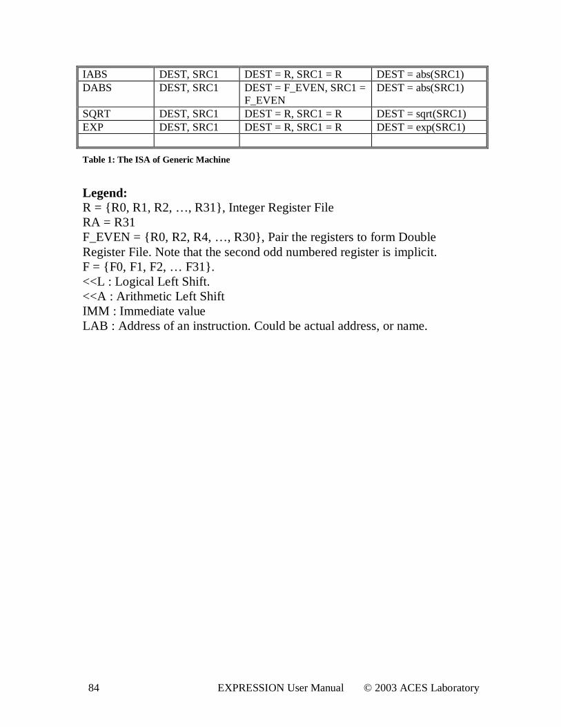
84 EXPRESSION User Manual © 2003 ACES Laboratory
IABS DEST, SRC1 DEST = R, SRC1 = R DEST = abs(SRC1) DABS DEST, SRC1 DEST = F_EVEN, SRC1 =
F_EVEN DEST = abs(SRC1)
SQRT DEST, SRC1 DEST = R, SRC1 = R DEST = sqrt(SRC1) EXP DEST, SRC1 DEST = R, SRC1 = R DEST = exp(SRC1)
Table 1: The ISA of Gener ic Machine
Legend: R = { R0, R1, R2, …, R31} , Integer Register File RA = R31 F_EVEN = { R0, R2, R4, …, R30} , Pair the registers to form Double Register File. Note that the second odd numbered register is implicit. F = { F0, F1, F2, … F31} . <<L : Logical Left Shift. <<A : Arithmetic Left Shift IMM : Immediate value LAB : Address of an instruction. Could be actual address, or name.