Embed Size (px)
Citation preview
User Manual HiBoost Hi13-23 Triple, quadruple and quintuple band consumer boosters 10 - 27dBm power range
Table of Content Table of Content ............................................................................................................... 2 Preface ............................................................................................................................... 3 Safety Warnings ................................................................................................................. 3 Overview ............................................................................................................................ 4 Glossary of Terms ............................................................................................................... 6 Package Contents ............................................................................................................ 7 Features .............................................................................................................................. 8 Booster’s Port Description ................................................................................................. 9 LCD Introduction ............................................................................................................... 9 Control Button operation ............................................................................................... 11 Manual gain control (MGC) .......................................................................................... 12 Install Hiboost Booster System ........................................................................................ 13
Before You Install ...................................................................................................... 13 Installation Overview ............................................................................................... 13
Step 1. Install Outdoor Antenna ...................................................................... 15 Step 2.Install Indoor Antenna .......................................................................... 18 Step 3.Install Signal Booster .............................................................................. 19 Step 4.Booster Commissioning ........................................................................ 20
Main Specifications ......................................................................................................... 25 Troubleshooting ............................................................................................................... 26 Product Warranty ............................................................................................................ 26 Huaptec Contact Details ............................................................................................... 27
2
Preface This user manual describes design, installation, commissioning and maintenance
of Hiboost wide band consumer single and dual band boosters.
Please, read user manual carefully before installing and maintaining the boosters. The information in this manual is subject to change without prior notice. Opinions
are welcomed about the manual improvement.
Note: This User Manual is about standard Huaptec consumer booster selection.
Other models can be obtained upon request.
Safety Warnings Users must follow the principlesstated below:
Booster should follow system requirements of mobile signal enhancement equipment, assure good grounding and lightning protection.
Booster’s power supply voltage should meet the standards of security requirements; any operation should be carried out only after cutting off power in advance. Only the professional is authorized for the operation.
Do not dismantle machine, maintain or displace accessories by yourself. In this way the equipment can be damaged andyou caneven get an electric shock.
Do not open the booster, touch the module of booster, or open the cover of module to touch the electronic component. The components will be damaged due to electrostatic.
Keep away from heating equipment, because the booster will dissipate heat during working. And do not cover booster with anything that influences heat-dissipation.
3
Overview
Hiboost triple, quadruple and quintuple band consumer boosters are designed to
help mobile users to amplify weak cell phone signal.
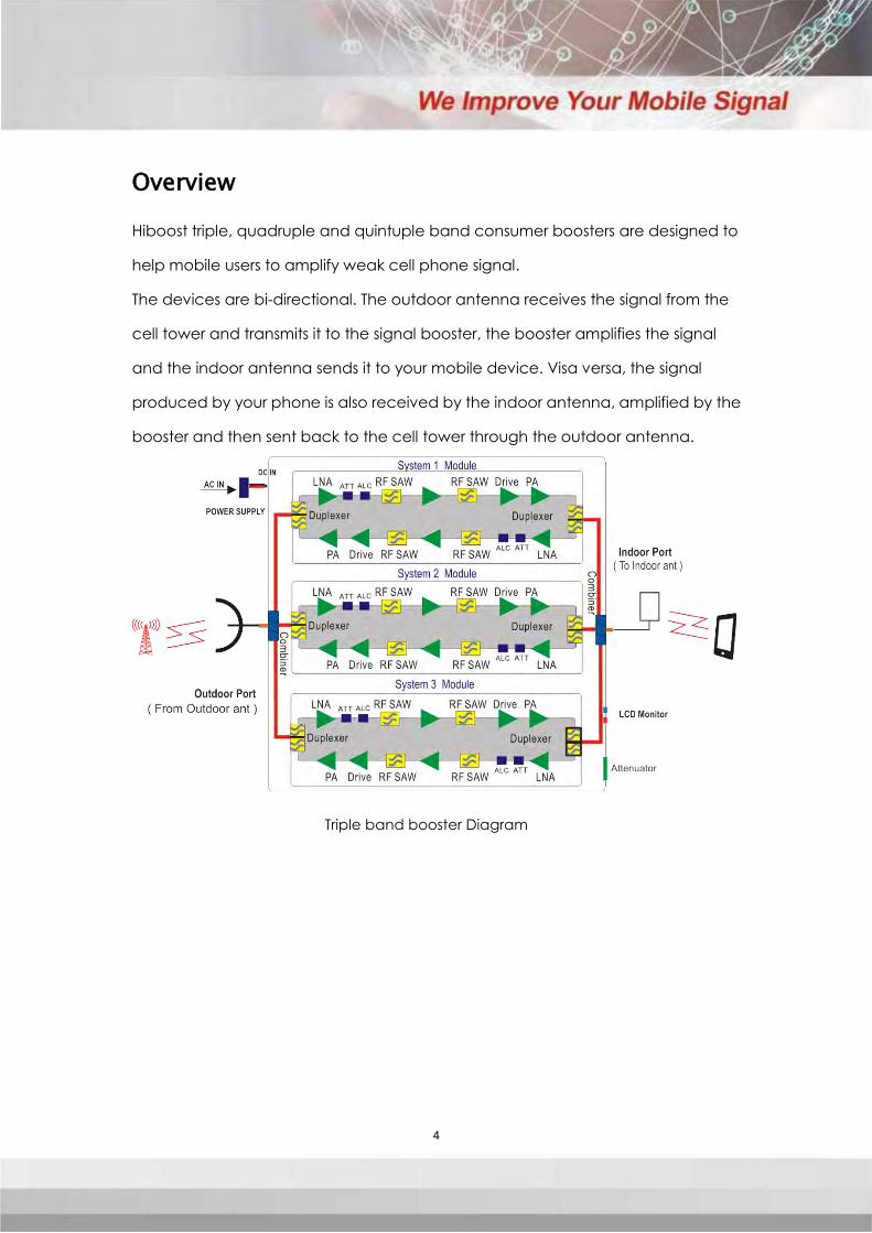
The devices are bi-directional. The outdoor antenna receives the signal from the
cell tower and transmits it to the signal booster, the booster amplifies the signal
and the indoor antenna sends it to your mobile device. Visa versa, the signal
produced by your phone is also received by the indoor antenna, amplified by the
booster and then sent back to the cell tower through the outdoor antenna.
Triple band booster Diagram
4
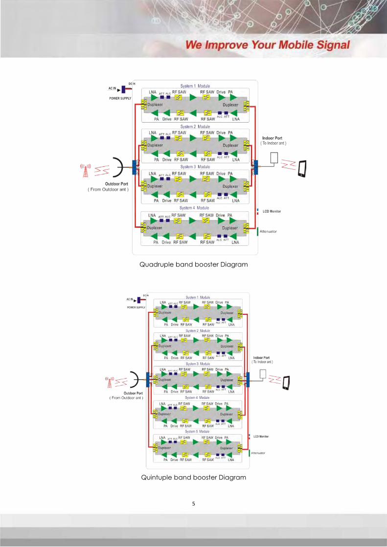
Quadruple band booster Diagram
Quintuple band booster Diagram
5
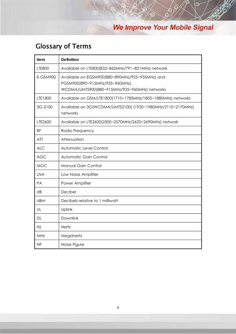
Glossary of Terms
Item Definition
LTE800 Available on LTE800(832~862MHz/791~821MHz) network
E-GSM900 Available on EGSM900(880~890MHz/925~935MHz) and PGSM900(890~915MHz/935~960MHz), WCDMA/UMTS900(880~915MHz/925~960MHz) networks
LTE1800 Available on GSM/LTE1800(1710~1785MHz/1805~1880MHz) networks
3G-2100 Available on 3G(WCDMA/UMTS2100) (1920~1980MHz/2110~2170MHz) networks
LTE2600 Available on LTE2600(2500~2570MHz/2620~2690MHz) network
RF Radio Frequency
ATT Attenuation
ALC Automatic Level Control
AGC Automatic Gain Control
MGC Manual Gain Control
LNA Low Noise Amplifier
PA Power Amplifier
dB Decibel
dBm Decibels relative to 1 milliwatt
UL Uplink
DL Downlink
Hz Hertz
MHz Megahertz
NF Noise Figure
6
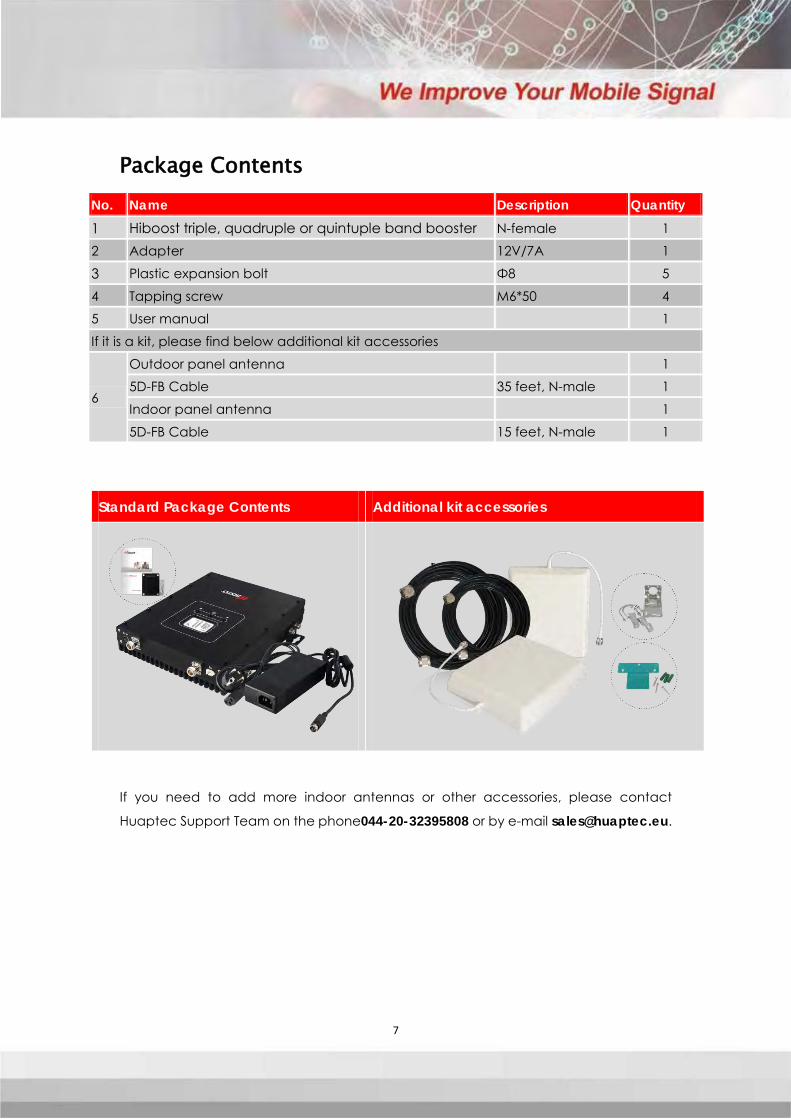
Package Contents No. Name Description Quantity
1 Hiboost triple, quadruple or quintuple band booster
N-female 1 2 Adapter 12V/7A 1
3 Plastic expansion bolt Φ8 5
4 Tapping screw M6*50 4 5 User manual 1
If it is a kit, please find below additional kit accessories
6
Outdoor panel antenna 1 5D-FB Cable 35 feet, N-male 1
Indoor panel antenna 1
5D-FB Cable 15 feet, N-male 1
Standard Package Contents Additional kit accessories
If you need to add more indoor antennas or other accessories, please contact
Huaptec Support Team on the phone044-20-32395808 or by e-mail [email protected].
7
Features
Embedded CPU, self-adaptive intelligent system very easy to use and install,
better performance is guaranteed even under complicated and constantly
changing RF environment conditions.
ISO: Intelligent isolation processing to avoid self-oscillation, quite wide
adjusting range to stabilize the signal strength/quality for clearer voice/ higher
data speed and avoid interference with mobile networks.
ALC: Intelligent automatic level control, quite wide adjusting range to stabilize
the output power and improve the signal quality for clearer voice and higher
data download speed.
LCD Display: Displays ISO status, ALC status, actual gain and downlink output
power which makes booster installation and troubleshooting much easier.
MGC: Control buttons to adjust the gain for both uplink and downlink
independently, 31dB range.
Excellent RF performance, larger coverage area, clearer voice and higher
data download speeds.
Elegant design, compact size, very low power consumption to minimize cost
during operation and low heat dissipation.
8
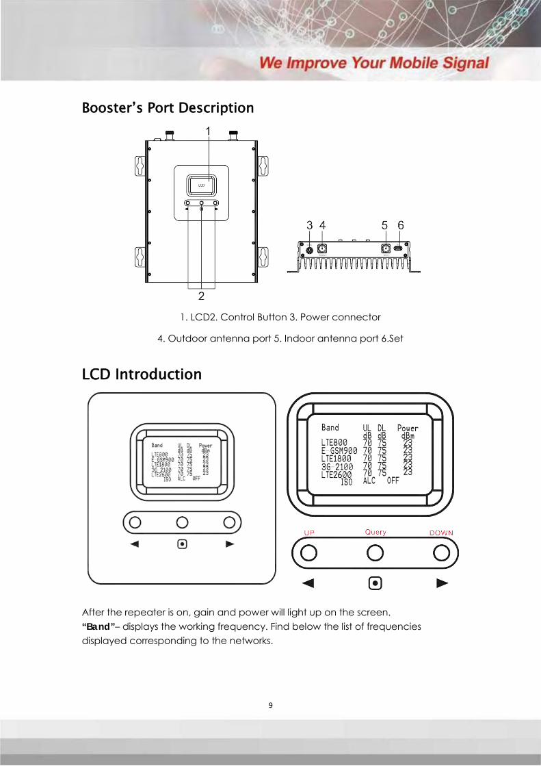
Booster’s Port Description
1. LCD2. Control Button 3. Power connector
4. Outdoor antenna port 5. Indoor antenna port 6.Set
LCD Introduction
After the repeater is on, gain and power will light up on the screen.“Band”– displays the working frequency. Find below the list of frequencies displayed corresponding to the networks.
9
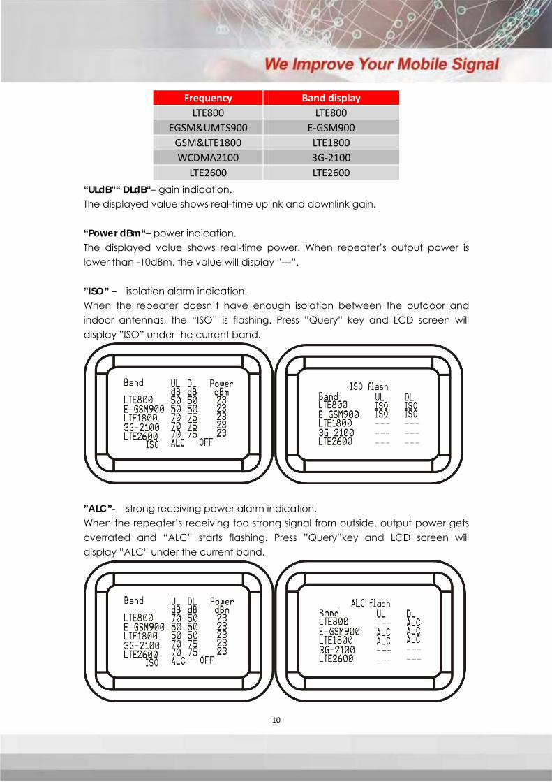
“ULdB”“ DLdB“– gain indication. The displayed value shows real-time uplink and downlink gain. “Power dBm“– power indication. The displayed value shows real-time power. When repeater’s output power is lower than -10dBm, the value will display ”---”. ”ISO” – isolation alarm indication. When the repeater doesn’t have enough isolation between the outdoor and indoor antennas, the “ISO” is flashing. Press ”Query” key and LCD screen will display ”ISO” under the current band.
”ALC”- strong receiving power alarm indication. When the repeater’s receiving too strong signal from outside, output power gets overrated and “ALC” starts flashing. Press ”Query”key and LCD screen will display ”ALC” under the current band.
Frequency Band display LTE800 LTE800
EGSM&UMTS900 E-GSM900 GSM<E1800 LTE1800 WCDMA2100 3G-2100
LTE2600 LTE2600
10
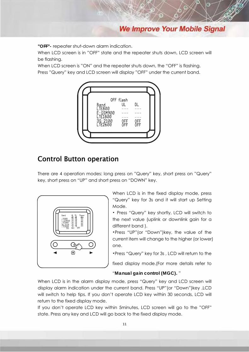
”OFF”- repeater shut-down alarm indication. When LCD screen is in ”OFF” state and the repeater shuts down, LCD screen will be flashing. When LCD screen is ”ON” and the repeater shuts down, the “OFF” is flashing. Press ”Query” key and LCD screen will display ”OFF” under the current band.
Control Button operation
There are 4 operation modes: long press on ”Query” key, short press on ”Query” key, short press on “UP” and short press on “DOWN” key.
When LCD is in the fixed display mode, press “Query” key for 3s and it will start up Setting Mode. • Press “Query” key shortly, LCD will switch to the next value (uplink or downlink gain for a different band ). •Press “UP”(or “Down”)key, the value of the current item will change to the higher (or lower) one.
•Press “Query” key for 3s , LCD will return to the
fixed display mode.(For more details refer to
“Manual gain control (MGC). ”
When LCD is in the alarm display mode, press “Query” key and LCD screen will display alarm indication under the current band. Press “UP”(or “Down”)key ,LCD will switch to help tips. If you don’t operate LCD key within 30 seconds, LCD will return to the fixed display mode. If you don’t operate LCD key within 5minutes, LCD screen will go to the ”OFF” state. Press any key and LCD will go back to the fixed display mode.
11
Manual gain control (MGC)
Since the booster has intelligent software system, MGC attenuation is not needed, except for the cases when you don't feel comfortable about ISO or ALC flashing, or in some extreme cases you might need to attenuate gain value. When LCD is in the fixed display mode, press “Query” key for 3s. It will start up the Setting Mode and make the screen stay in the current status. • Press “Query” key shortly, LCD will switch to the next value (uplink or downlink gain for a different band ). •Press “UP”key once shortly, the gain will increase by 1dB, press“DOWN”once shortly, the gain will be reduced by 1dB. •Press “Query” key for 3 seconds , LCD will return to the fixed display mode. Note: In case you need to adjust gain, please ensure uplink gain to be equal with or to be 5dB less than downlink gain, uplink gain shouldn’t be more than downlink gain in order to avoid interference with mobile network
12
Install Hiboost Booster System
Before You Install
• Make sure you have sufficient cable length between the outdoor/indoor
antennas and the booster in case you have not a standard kit
• Make sure the place where you install the booster is near to one existing
electrical outlet. It should also be well ventilated, away from excessive heat,
moisture, and direct sunlight.
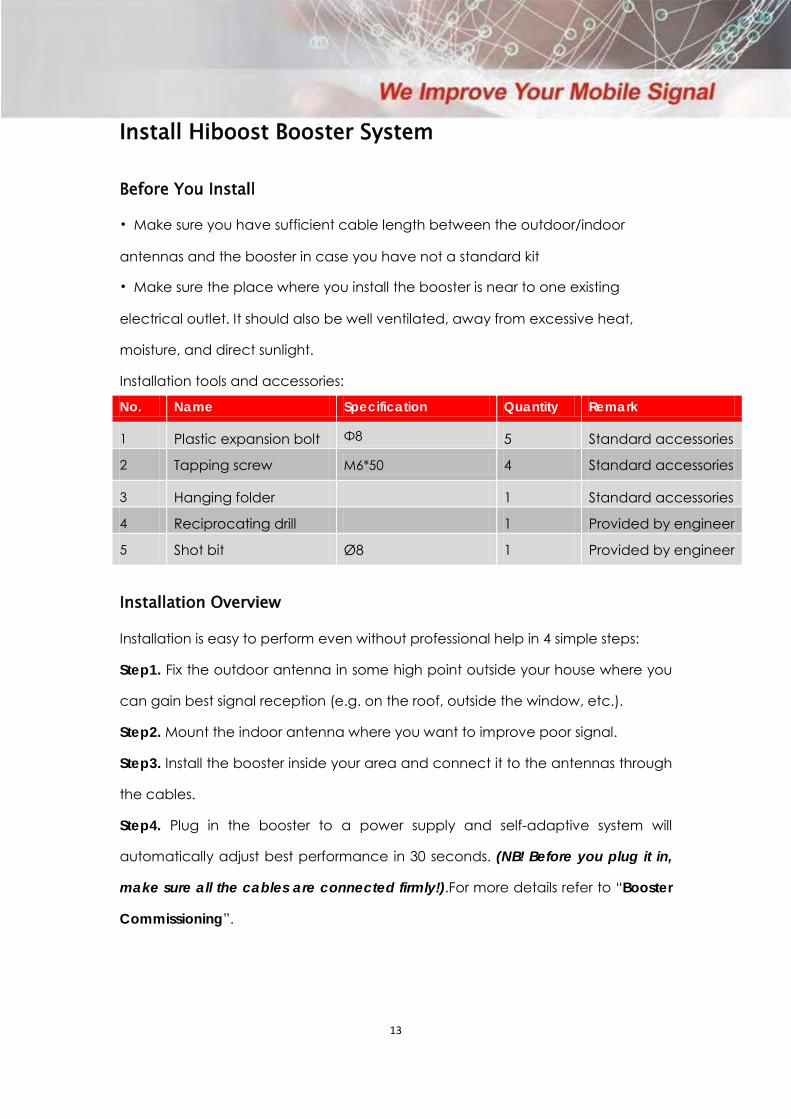
Installation tools and accessories:
No. Name Specification Quantity Remark
1 Plastic expansion bolt Φ8 5 Standard accessories
2 Tapping screw M6*50 4 Standard accessories
3 Hanging folder 1 Standard accessories
4 Reciprocating drill 1 Provided by engineer
5 Shot bit Ø8 1 Provided by engineer
Installation Overview
Installation is easy to perform even without professional help in 4 simple steps:
Step1. Fix the outdoor antenna in some high point outside your house where you
can gain best signal reception (e.g. on the roof, outside the window, etc.).
Step2. Mount the indoor antenna where you want to improve poor signal.
Step3. Install the booster inside your area and connect it to the antennas through
the cables.
Step4. Plug in the booster to a power supply and self-adaptive system will
automatically adjust best performance in 30 seconds. (NB! Before you plug it in,
make sure all the cables are connected firmly!).For more details refer to “Booster
Commissioning”.
13
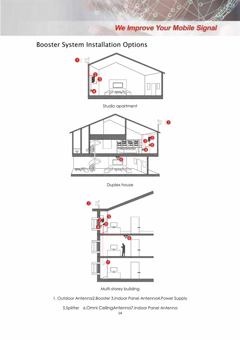
Booster System Installation Options
Studio apartment
Duplex house
Multi-storey building
1. Outdoor Antenna2.Booster 3.Indoor Panel Antenna4.Power Supply
5.Splitter 6.Omni CeilingAntenna7.Indoor Panel Antenna 14
Step 1. Install Outdoor Antenna
1.1 How to find the place with the strongest receiving signal
The booster’s main function is to improve weak RF signal inside a house, office or
any other indoor area. The receiving strength of the outdoor antenna and the
strength of the signal reception outdoors directly affect the efficiency of indoor
coverage. That’s why it’s crucially important to install the outdoor antenna in the
point where signal reception is the strongest.
There are two methods to find the strongest receiving signal. One is to use
booster’s LCD display, the other is to use mobile phone to test signal bars. We’d
highly recommend you to use LCD display as this method is more accurate.
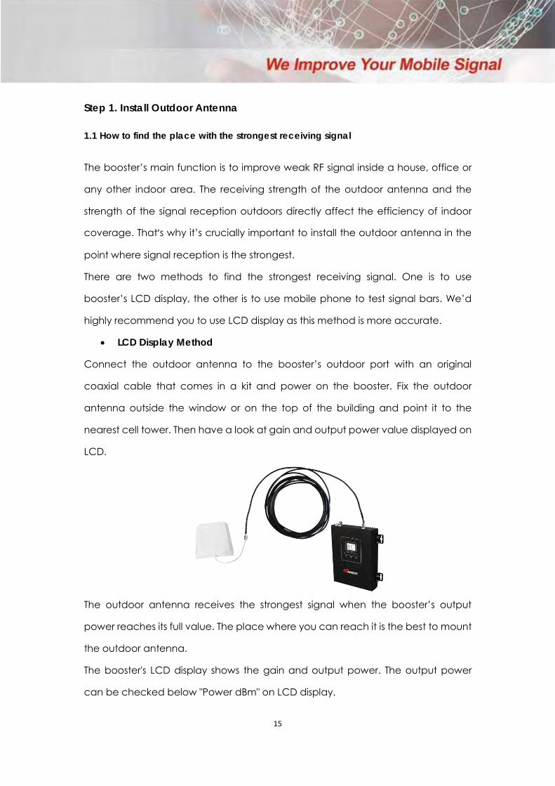
• LCD Display Method
Connect the outdoor antenna to the booster’s outdoor port with an original
coaxial cable that comes in a kit and power on the booster. Fix the outdoor
antenna outside the window or on the top of the building and point it to the
nearest cell tower. Then have a look at gain and output power value displayed on
LCD.
The outdoor antenna receives the strongest signal when the booster’s output
power reaches its full value. The place where you can reach it is the best to mount
the outdoor antenna.
The booster's LCD display shows the gain and output power. The output power
can be checked below "Power dBm" on LCD display.
15
Remark: when ALC shows up flashing, it means the receiving signal power is
stronger than the system needs it. It is recommended to adjust outdoor antenna
position unless ALC alarm disappears. Or you can leave it as it is to let the booster
self-adjust automatically. However when ALC flashes, and the displayed gain is
more than 30dB less than rated gain value, try to adjust outdoor antenna to
decrease the receiving power.
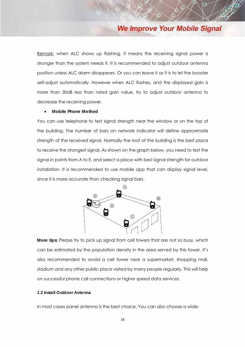
• Mobile Phone Method
You can use telephone to test signal strength near the window or on the top of
the building. The number of bars on network indicator will define approximate
strength of the received signal. Normally the roof of the building is the best place
to receive the strongest signal. As shown on the graph below, you need to test the
signal in points from A to E, and select a place with best signal strength for outdoor
installation. It is recommended to use mobile app that can display signal level,
since it is more accurate than checking signal bars.
More tips: Please try to pick up signal from cell towers that are not so busy, which
can be estimated by the population density in the area served by this tower. It’s
also recommended to avoid a cell tower near a supermarket, shopping mall,
stadium and any other public place visited by many people regularly. This will help
on successful phone call connections or higher speed data services.
1.2 Install Outdoor Antenna
In most cases panel antenna is the best choice. You can also choose a wide-
16
band yagi antenna as an option.
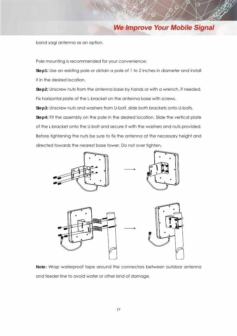
Pole mounting is recommended for your convenience:
Step1: Use an existing pole or obtain a pole of 1 to 2 inches in diameter and install
it in the desired location.
Step2: Unscrew nuts from the antenna base by hands or with a wrench, if needed.
Fix horizontal plate of the L-bracket on the antenna base with screws.
Step3: Unscrew nuts and washers from U-bolt, slide both brackets onto U-bolts.
Step4: Fit the assembly on the pole in the desired location. Slide the vertical plate
of the L-bracket onto the U-bolt and secure it with the washers and nuts provided.
Before tightening the nuts be sure to fix the antenna at the necessary height and
directed towards the nearest base tower. Do not over tighten.
Note: Wrap waterproof tape around the connectors between outdoor antenna
and feeder line to avoid water or other kind of damage.
17
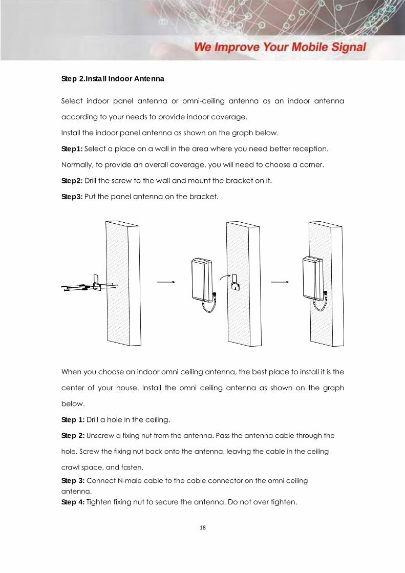
Step 2.Install Indoor Antenna
Select indoor panel antenna or omni-ceiling antenna as an indoor antenna
according to your needs to provide indoor coverage.
Install the indoor panel antenna as shown on the graph below.
Step1: Select a place on a wall in the area where you need better reception.
Normally, to provide an overall coverage, you will need to choose a corner.
Step2: Drill the screw to the wall and mount the bracket on it.
Step3: Put the panel antenna on the bracket.
When you choose an indoor omni ceiling antenna, the best place to install it is the
center of your house. Install the omni ceiling antenna as shown on the graph
below.
Step 1: Drill a hole in the ceiling.
Step 2: Unscrew a fixing nut from the antenna. Pass the antenna cable through the
hole. Screw the fixing nut back onto the antenna, leaving the cable in the ceiling
crawl space, and fasten.
Step 3: Connect N-male cable to the cable connector on the omni ceiling antenna. Step 4: Tighten fixing nut to secure the antenna. Do not over tighten.
18
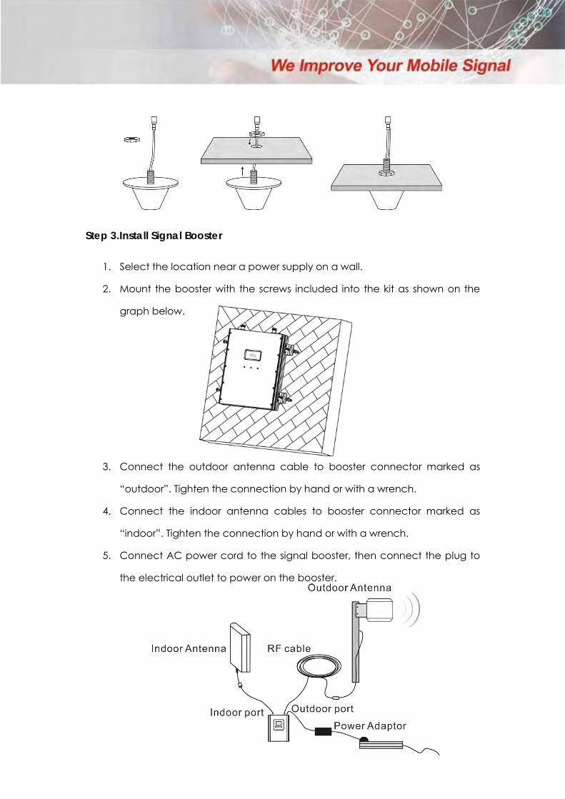
Step 3.Install Signal Booster
1. Select the location near a power supply on a wall.
2. Mount the booster with the screws included into the kit as shown on the
graph below.
3. Connect the outdoor antenna cable to booster connector marked as
“outdoor”. Tighten the connection by hand or with a wrench.
4. Connect the indoor antenna cables to booster connector marked as
“indoor”. Tighten the connection by hand or with a wrench.
5. Connect AC power cord to the signal booster, then connect the plug to
the electrical outlet to power on the booster.
19
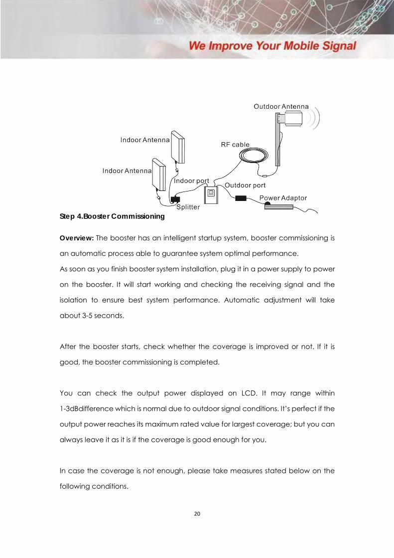
Step 4.Booster Commissioning
Overview: The booster has an intelligent startup system, booster commissioning is
an automatic process able to guarantee system optimal performance.
As soon as you finish booster system installation, plug it in a power supply to power
on the booster. It will start working and checking the receiving signal and the
isolation to ensure best system performance. Automatic adjustment will take
about 3-5 seconds.
After the booster starts, check whether the coverage is improved or not. If it is
good, the booster commissioning is completed.
You can check the output power displayed on LCD. It may range within
1-3dBdifference which is normal due to outdoor signal conditions. It’s perfect if the
output power reaches its maximum rated value for largest coverage; but you can
always leave it as it is if the coverage is good enough for you.
In case the coverage is not enough, please take measures stated below on the
following conditions.
20
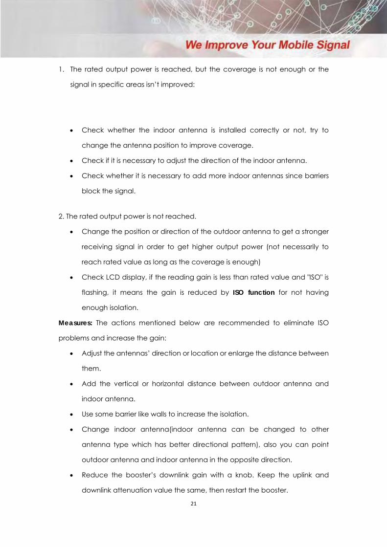
1. The rated output power is reached, but the coverage is not enough or the
signal in specific areas isn’t improved:
• Check whether the indoor antenna is installed correctly or not, try to
change the antenna position to improve coverage.
• Check if it is necessary to adjust the direction of the indoor antenna.
• Check whether it is necessary to add more indoor antennas since barriers
block the signal.
2. The rated output power is not reached.
• Change the position or direction of the outdoor antenna to get a stronger
receiving signal in order to get higher output power (not necessarily to
reach rated value as long as the coverage is enough)
• Check LCD display, if the reading gain is less than rated value and "ISO" is
flashing, it means the gain is reduced by ISO function for not having
enough isolation.
Measures: The actions mentioned below are recommended to eliminate ISO
problems and increase the gain:
• Adjust the antennas’ direction or location or enlarge the distance between
them.
• Add the vertical or horizontal distance between outdoor antenna and
indoor antenna.
• Use some barrier like walls to increase the isolation.
• Change indoor antenna(indoor antenna can be changed to other
antenna type which has better directional pattern), also you can point
outdoor antenna and indoor antenna in the opposite direction.
• Reduce the booster’s downlink gain with a knob. Keep the uplink and
downlink attenuation value the same, then restart the booster.
21
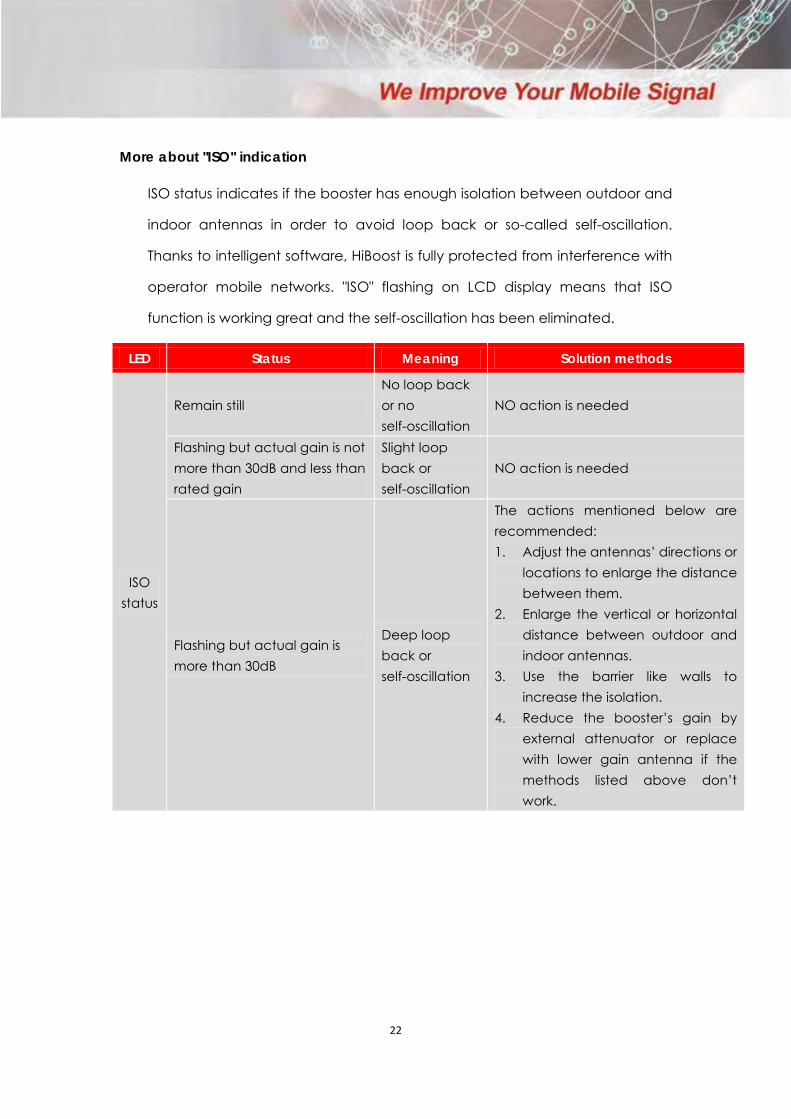
More about "ISO" indication
ISO status indicates if the booster has enough isolation between outdoor and
indoor antennas in order to avoid loop back or so-called self-oscillation.
Thanks to intelligent software, HiBoost is fully protected from interference with
operator mobile networks. "ISO" flashing on LCD display means that ISO
function is working great and the self-oscillation has been eliminated.
LED Status Meaning Solution methods
ISO status
Remain still No loop back or no self-oscillation
NO action is needed
Flashing but actual gain is not more than 30dB and less than rated gain
Slight loop back or self-oscillation
NO action is needed
Flashing but actual gain is more than 30dB
Deep loop back or self-oscillation
The actions mentioned below are recommended: 1. Adjust the antennas’ directions or
locations to enlarge the distance between them.
2. Enlarge the vertical or horizontal distance between outdoor and indoor antennas.
3. Use the barrier like walls to increase the isolation.
4. Reduce the booster’s gain by external attenuator or replace with lower gain antenna if the methods listed above don’t work.
22
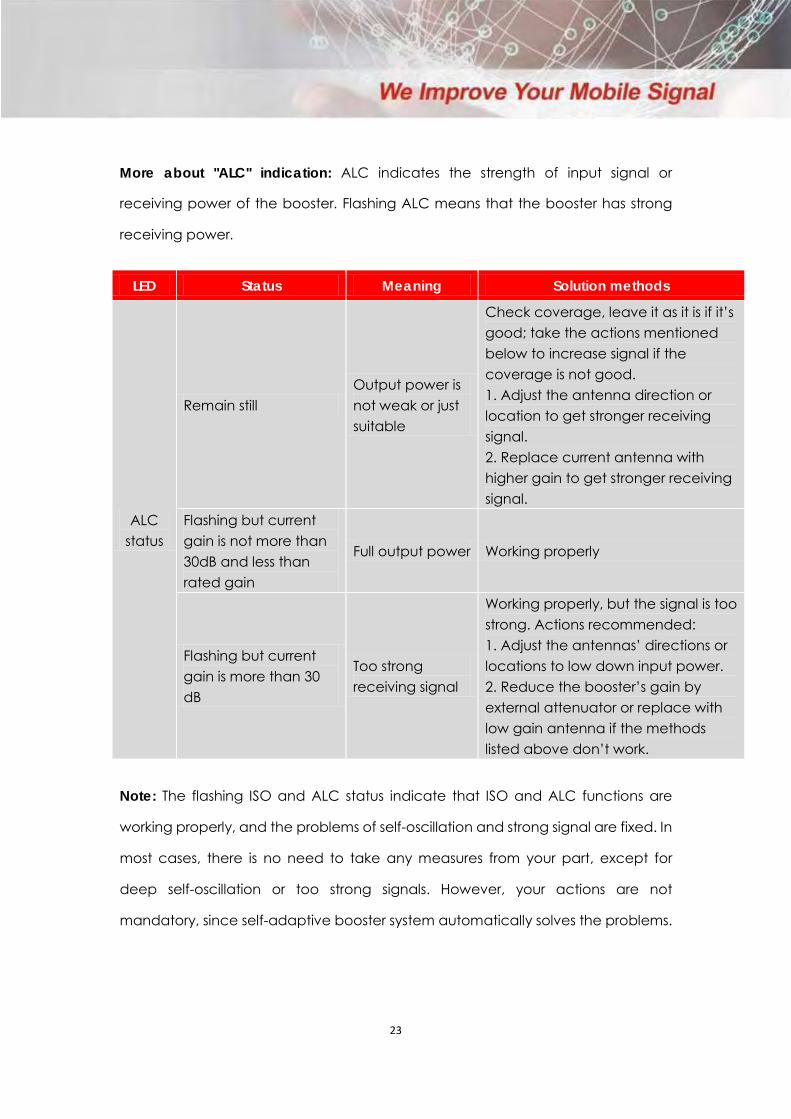
More about "ALC" indication: ALC indicates the strength of input signal or
receiving power of the booster. Flashing ALC means that the booster has strong
receiving power.
LED Status Meaning Solution methods
ALC status
Remain still Output power is not weak or just suitable
Check coverage, leave it as it is if it’s good; take the actions mentioned below to increase signal if the coverage is not good. 1. Adjust the antenna direction or location to get stronger receiving signal. 2. Replace current antenna with higher gain to get stronger receiving signal.
Flashing but current gain is not more than 30dB and less than rated gain
Full output power Working properly
Flashing but current gain is more than 30 dB
Too strong receiving signal
Working properly, but the signal is too strong. Actions recommended: 1. Adjust the antennas’ directions or locations to low down input power. 2. Reduce the booster’s gain by external attenuator or replace with low gain antenna if the methods listed above don’t work.
Note: The flashing ISO and ALC status indicate that ISO and ALC functions are
working properly, and the problems of self-oscillation and strong signal are fixed. In
most cases, there is no need to take any measures from your part, except for
deep self-oscillation or too strong signals. However, your actions are not
mandatory, since self-adaptive booster system automatically solves the problems.
23
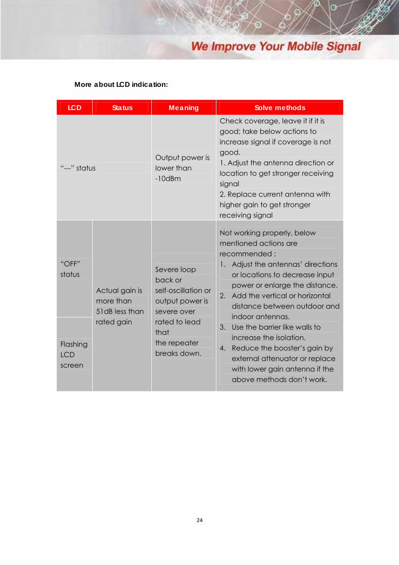
More about LCD indication:
LCD Status Meaning Solve methods
“---” status Output power is lower than -10dBm
Check coverage, leave it if it is good; take below actions to increase signal if coverage is not good. 1. Adjust the antenna direction or location to get stronger receiving signal 2. Replace current antenna with higher gain to get stronger receiving signal
“OFF” status
Actual gain is more than 51dB less than rated gain
Severe loop back or self-oscillation or output power is severe over rated to lead that the repeater breaks down.
Not working properly, below mentioned actions are recommended : 1. Adjust the antennas’ directions
or locations to decrease input power or enlarge the distance.
2. Add the vertical or horizontal distance between outdoor and indoor antennas.
3. Use the barrier like walls to increase the isolation.
4. Reduce the booster’s gain by external attenuator or replace with lower gain antenna if the above methods don’t work.
Flashing LCD screen
24
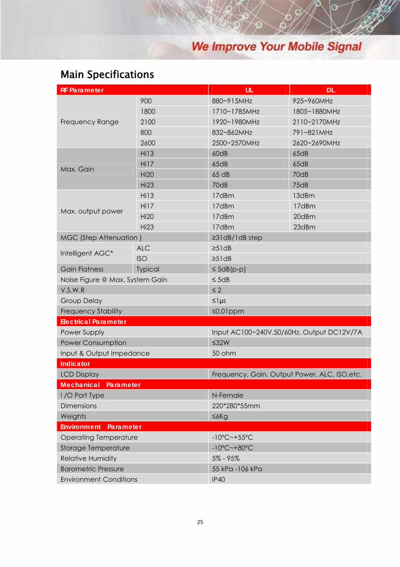
Main Specifications RF Parameter UL DL
Frequency Range
900 880~915MHz 925~960MHz 1800 1710~1785MHz 1805~1880MHz 2100 1920~1980MHz 2110~2170MHz 800 832~862MHz 791~821MHz 2600 2500~2570MHz 2620~2690MHz
Max. Gain
Hi13 60dB 65dB Hi17 65dB 65dB Hi20 65 dB 70dB Hi23 70dB 75dB
Max. output power
Hi13 17dBm 13dBm Hi17 17dBm 17dBm Hi20 17dBm 20dBm Hi23 17dBm 23dBm
MGC (Step Attenuation ) ≥31dB/1dB step
Intelligent AGC* ALC ≥51dB ISO ≥51dB
Gain Flatness Typical ≤ 5dB(p-p) Noise Figure @ Max. System Gain ≤ 5dB V.S.W.R ≤ 2 Group Delay ≤1μs Frequency Stability ≤0.01ppm Electrical Parameter Power Supply Input AC100~240V.50/60Hz, Output DC12V/7A Power Consumption ≤32W Input & Output Impedance 50 ohm Indicator LCD Display Frequency, Gain, Output Power, ALC, ISO,etc. Mechanical Parameter I /O Port Type N-Female Dimensions 220*280*55mm Weights ≤6Kg Environment Parameter Operating Temperature -10ºC~+55ºC Storage Temperature -10ºC~+80ºC Relative Humidity 5% - 95% Barometric Pressure 55 kPa -106 kPa Environment Conditions IP40
25
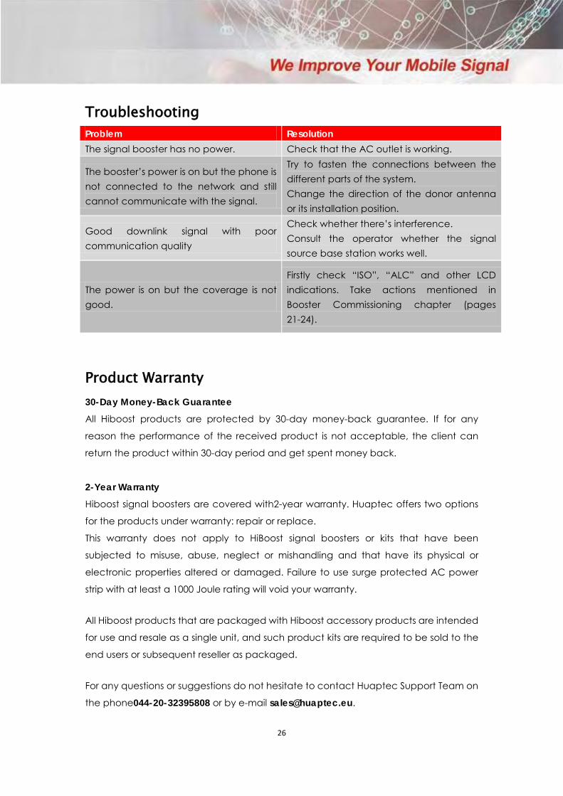
Troubleshooting Problem Resolution The signal booster has no power. Check that the AC outlet is working.
The booster’s power is on but the phone is not connected to the network and still cannot communicate with the signal.
Try to fasten the connections between the different parts of the system. Change the direction of the donor antenna or its installation position.
Good downlink signal with poor communication quality
Check whether there’s interference. Consult the operator whether the signal source base station works well.
The power is on but the coverage is not good.
Firstly check “ISO”, “ALC” and other LCD indications. Take actions mentioned in Booster Commissioning chapter (pages 21-24).
Product Warranty 30-Day Money-Back Guarantee
All Hiboost products are protected by 30-day money-back guarantee. If for any
reason the performance of the received product is not acceptable, the client can
return the product within 30-day period and get spent money back.
2-Year Warranty
Hiboost signal boosters are covered with2-year warranty. Huaptec offers two options
for the products under warranty: repair or replace.
This warranty does not apply to HiBoost signal boosters or kits that have been
subjected to misuse, abuse, neglect or mishandling and that have its physical or
electronic properties altered or damaged. Failure to use surge protected AC power
strip with at least a 1000 Joule rating will void your warranty.
All Hiboost products that are packaged with Hiboost accessory products are intended
for use and resale as a single unit, and such product kits are required to be sold to the
end users or subsequent reseller as packaged.
For any questions or suggestions do not hesitate to contact Huaptec Support Team on
the phone044-20-32395808 or by e-mail [email protected].
26
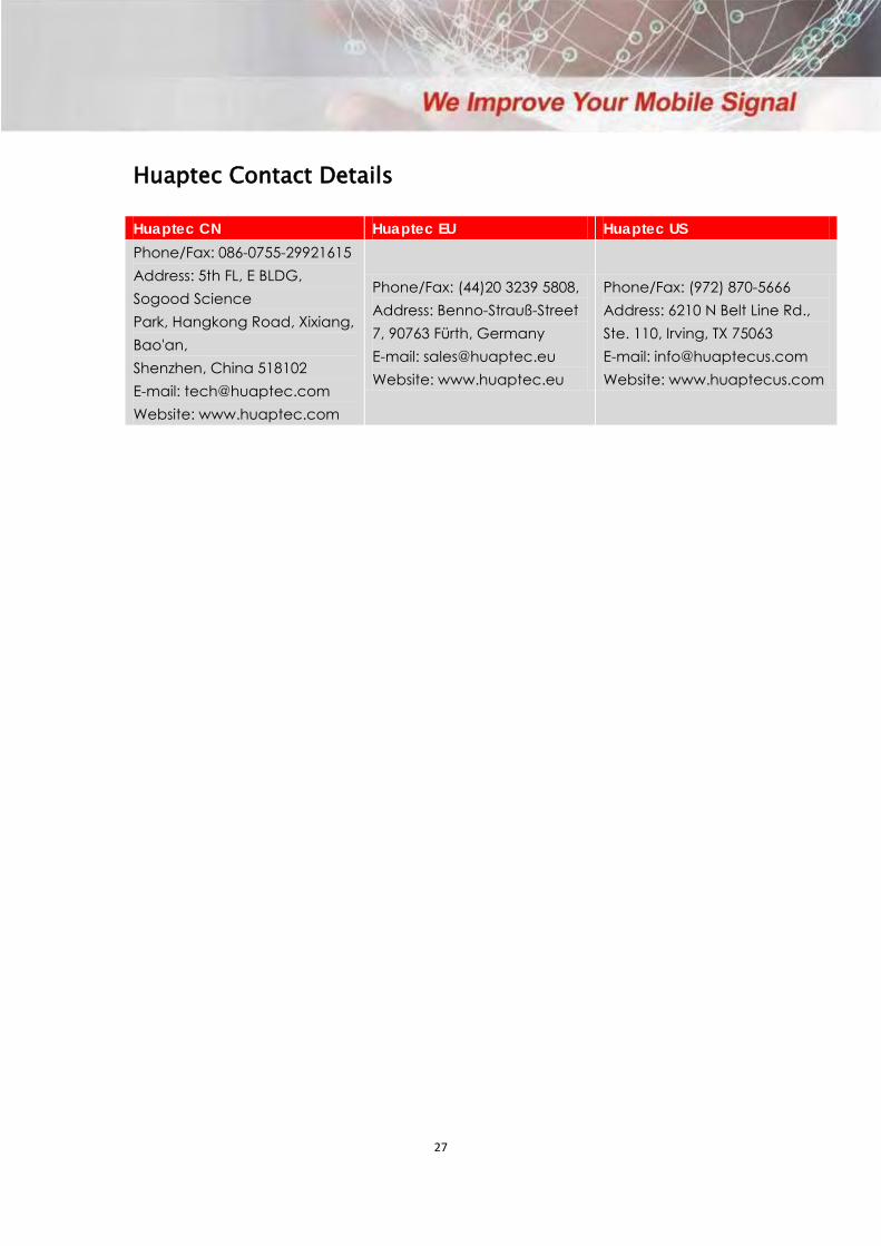
Huaptec Contact Details
Huaptec CN Huaptec EU Huaptec US Phone/Fax: 086-0755-29921615 Address: 5th FL, E BLDG, Sogood Science Park, Hangkong Road, Xixiang, Bao'an, Shenzhen, China 518102 E-mail: [email protected] Website: www.huaptec.com
Phone/Fax: (44)20 3239 5808, Address: Benno-Strauß-Street 7, 90763 Fürth, Germany E-mail: [email protected] Website: www.huaptec.eu
Phone/Fax: (972) 870-5666 Address: 6210 N Belt Line Rd., Ste. 110, Irving, TX 75063 E-mail: [email protected] Website: www.huaptecus.com
27

28