Embed Size (px)
Citation preview
v1.4
USER MANUAL
Models:LINK-EVOLINK-EVO-VLINK-W
CELLULAR TRAIL CAMERA
support.spypoint.com
1-888-779-7646
2
THANK YOU FOR CHOOSING A SPYPOINT PRODUCT.
This manual will guide you through all the features of your device so that you will get optimal use out of your SPYPOINT product. We strive on offering all customers a positive, user friendly experience that will have a lasting impression.
JOIN THE SPYPOINT COMMUNITY
ABOUT US
Our passion and commitment to the hunting industry has highly contributed to our success story. We are very proud of the path our home grown company has taken and very grateful for every opportunity we have had. Quality, personalized service and support were the foundation for us and we continue to pursue this rule of thumb as our business grows.
Team work is the most important word for us at SPYPOINT and is the key to our innovations and constant progress. A company is only as successful as its communication and team efforts. We are forever thankful to the team that supports us on a daily basis but furthermore we are honored to have such talented and committed individuals to call our SPYPOINT family.
facebook.com/SPYPOINT
twitter.com/SPYPOINTcamera
youtube.com/SPYPOINTtrailcam
3
Components ................................................................................. 4
SpecificationsLINK-EVO & LINK-EVO-V .................................................................. 6LINK-W .......................................................................................... 7
Power ........................................................................................... 8
Memory card & Busy LED .............................................................. 9
Getting started ............................................................................10
EVO software: Configuration & diagnosis tool ..............................11
SPYPOINT LINK App ....................................................................12
Installation & Mounting bracket ..................................................15
File transfer to a computer ..........................................................16
Available accessories ..................................................................17
Troubleshooting ..........................................................................18
Warranty & Repair .......................................................................20
Regulation ...................................................................................21
Table of contents
4
Components
1
2
7
3
6
9
11
12
13
14
15
16
4
5
8
10
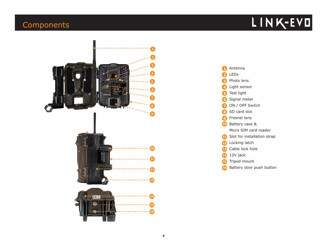
Antenna LEDs Photo lens Light sensor Test light Signal meter ON / OFF Switch SD card slot Fresnel lens Battery case & Micro SIM card reader Slot for installation strap Locking latch Cable lock hole 12V jack Tripod mount Battery door push button
12345678910
11
12
13
14
15
16
5
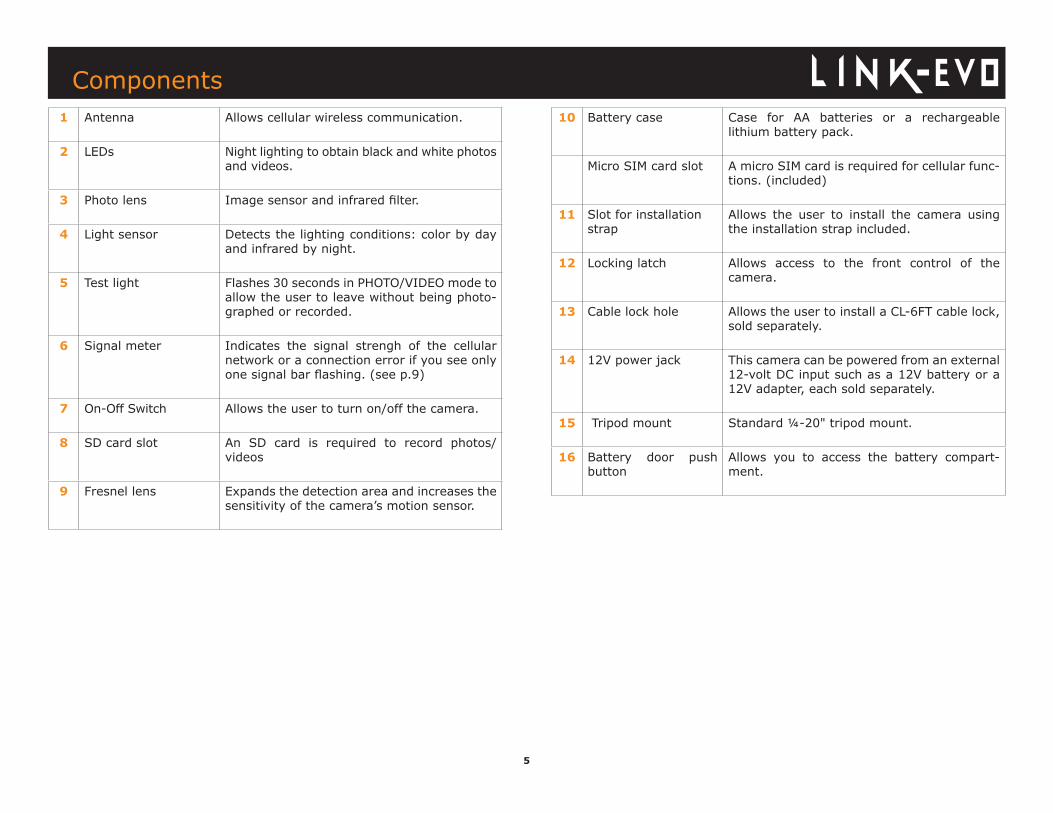
1 Antenna Allows cellular wireless communication.
2 LEDs Night lighting to obtain black and white photos and videos.
3 Photo lens Image sensor and infrared filter.
4 Light sensor Detects the lighting conditions: color by day and infrared by night.
5 Test light Flashes 30 seconds in PHOTO/VIDEO mode to allow the user to leave without being photo-graphed or recorded.
6 Signal meter Indicates the signal strengh of the cellular network or a connection error if you see only one signal bar flashing. (see p.9)
7 On-Off Switch Allows the user to turn on/off the camera.
8 SD card slot An SD card is required to record photos/ videos
9 Fresnel lens Expands the detection area and increases the sensitivity of the camera’s motion sensor.
10 Battery case Case for AA batteries or a rechargeable lithium battery pack.
Micro SIM card slot A micro SIM card is required for cellular func-tions. (included)
11 Slot for installation strap
Allows the user to install the camera using the installation strap included.
12 Locking latch Allows access to the front control of the camera.
13 Cable lock hole Allows the user to install a CL-6FT cable lock, sold separately.
14 12V power jack This camera can be powered from an external 12-volt DC input such as a 12V battery or a 12V adapter, each sold separately.
15 Tripod mount Standard ¼-20" tripod mount.
16 Battery door push button
Allows you to access the battery compart-ment.
Components
6
Specifications
Cellular transmission
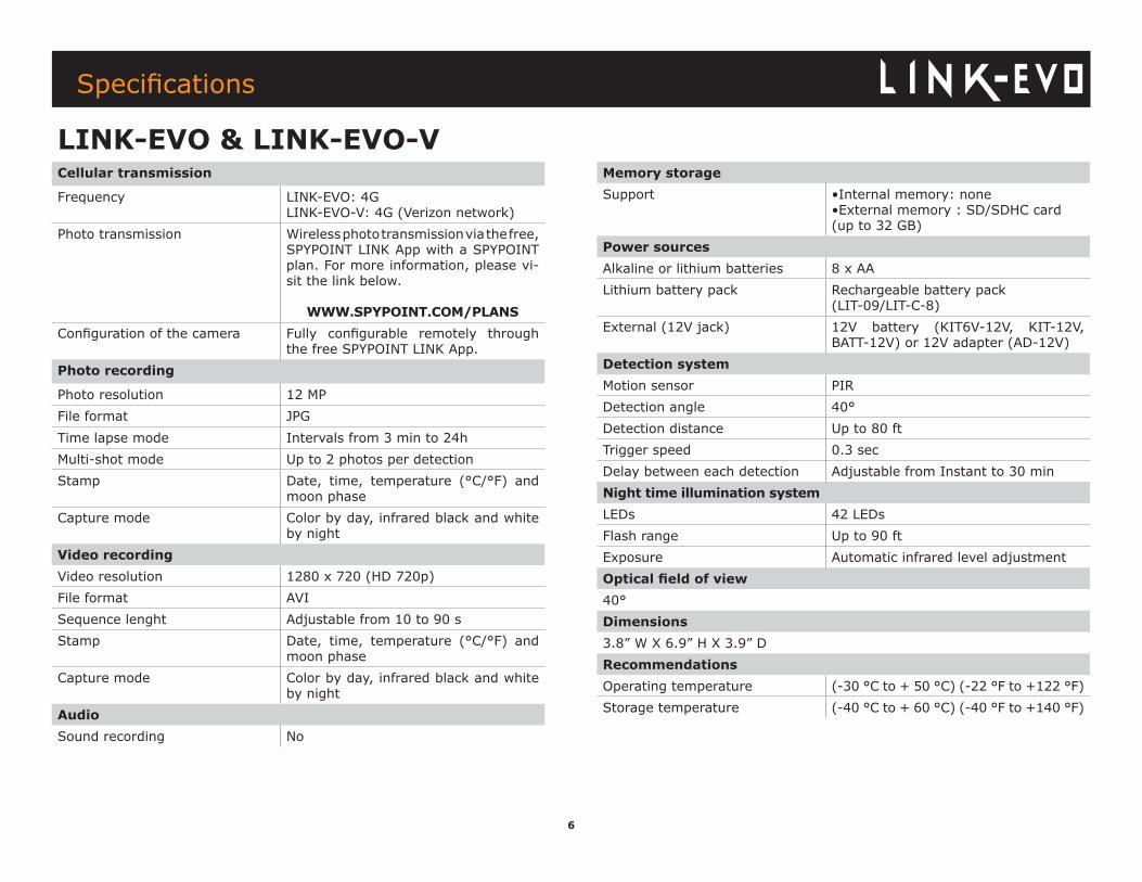
Frequency LINK-EVO: 4G LINK-EVO-V: 4G (Verizon network)
Photo transmission Wireless photo transmission via the free, SPYPOINT LINK App with a SPYPOINT plan. For more information, please vi-sit the link below.
WWW.SPYPOINT.COM/PLANSConfiguration of the camera Fully configurable remotely through
the free SPYPOINT LINK App.Photo recording
Photo resolution 12 MPFile format JPGTime lapse mode Intervals from 3 min to 24hMulti-shot mode Up to 2 photos per detectionStamp Date, time, temperature (°C/°F) and
moon phaseCapture mode Color by day, infrared black and white
by nightVideo recordingVideo resolution 1280 x 720 (HD 720p)File format AVISequence lenght Adjustable from 10 to 90 sStamp Date, time, temperature (°C/°F) and
moon phaseCapture mode Color by day, infrared black and white
by nightAudioSound recording No
Memory storageSupport •Internal memory: none
•External memory : SD/SDHC card (up to 32 GB)
Power sourcesAlkaline or lithium batteries 8 x AALithium battery pack Rechargeable battery pack
(LIT-09/LIT-C-8)External (12V jack) 12V battery (KIT6V-12V, KIT-12V,
BATT-12V) or 12V adapter (AD-12V)Detection systemMotion sensor PIR Detection angle 40°Detection distance Up to 80 ftTrigger speed 0.3 secDelay between each detection Adjustable from Instant to 30 minNight time illumination systemLEDs 42 LEDsFlash range Up to 90 ftExposure Automatic infrared level adjustmentOptical field of view40°Dimensions3.8” W X 6.9” H X 3.9” DRecommendationsOperating temperature (-30 °C to + 50 °C) (-22 °F to +122 °F)Storage temperature (-40 °C to + 60 °C) (-40 °F to +140 °F)
LINK-EVO & LINK-EVO-V
7
Specifications
Cellular transmission
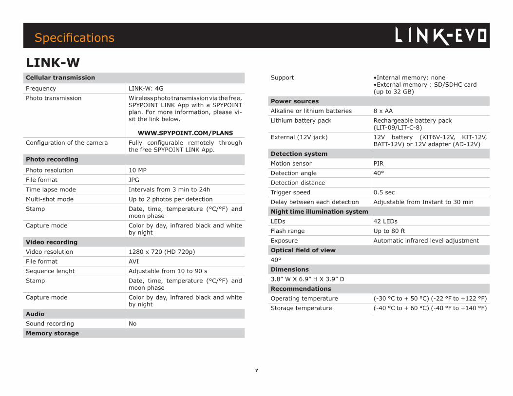
Frequency LINK-W: 4G Photo transmission Wireless photo transmission via the free,
SPYPOINT LINK App with a SPYPOINT plan. For more information, please vi-sit the link below.
WWW.SPYPOINT.COM/PLANSConfiguration of the camera Fully configurable remotely through
the free SPYPOINT LINK App.Photo recording
Photo resolution 10 MPFile format JPGTime lapse mode Intervals from 3 min to 24hMulti-shot mode Up to 2 photos per detectionStamp Date, time, temperature (°C/°F) and
moon phaseCapture mode Color by day, infrared black and white
by nightVideo recordingVideo resolution 1280 x 720 (HD 720p)File format AVISequence lenght Adjustable from 10 to 90 sStamp Date, time, temperature (°C/°F) and
moon phaseCapture mode Color by day, infrared black and white
by nightAudioSound recording NoMemory storage
Support •Internal memory: none•External memory : SD/SDHC card (up to 32 GB)
Power sourcesAlkaline or lithium batteries 8 x AALithium battery pack Rechargeable battery pack
(LIT-09/LIT-C-8)External (12V jack) 12V battery (KIT6V-12V, KIT-12V,
BATT-12V) or 12V adapter (AD-12V)Detection systemMotion sensor PIR Detection angle 40°Detection distanceTrigger speed 0.5 secDelay between each detection Adjustable from Instant to 30 minNight time illumination systemLEDs 42 LEDsFlash range Up to 80 ftExposure Automatic infrared level adjustmentOptical field of view40°Dimensions3.8” W X 6.9” H X 3.9” DRecommendationsOperating temperature (-30 °C to + 50 °C) (-22 °F to +122 °F)Storage temperature (-40 °C to + 60 °C) (-40 °F to +140 °F)
LINK-W
8
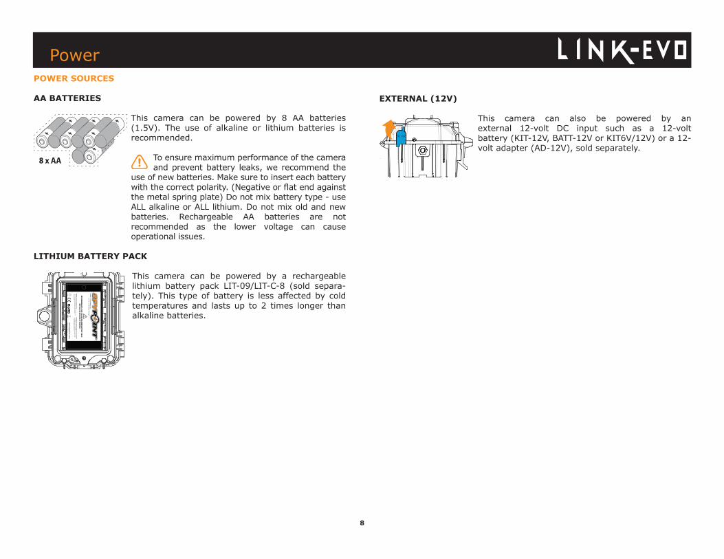
EXTERNAL (12V)
This camera can also be powered by an external 12-volt DC input such as a 12-volt battery (KIT-12V, BATT-12V or KIT6V/12V) or a 12-volt adapter (AD-12V), sold separately.
POWER SOURCES
AA BATTERIES
This camera can be powered by 8 AA batteries (1.5V). The use of alkaline or lithium batteries is recommended.
To ensure maximum performance of the camera and prevent battery leaks, we recommend the
use of new batteries. Make sure to insert each battery with the correct polarity. (Negative or flat end against the metal spring plate) Do not mix battery type - use ALL alkaline or ALL lithium. Do not mix old and new batteries. Rechargeable AA batteries are not recommended as the lower voltage can cause operational issues.
LITHIUM BATTERY PACK
This camera can be powered by a rechargeable lithium battery pack LIT-09/LIT-C-8 (sold separa-tely). This type of battery is less affected by cold temperatures and lasts up to 2 times longer than alkaline batteries.
Power
RECHARG
EABLE 7.4 VOLT LI-IO
N PO
LYMER BATTERY 2.0 Ah
RECYCLE OR D
ISPOSE O
F PROPERLY
Li-ionM
ade in China | Fabriqué en C
hine v2.3
ww
w.spypoint.com
PIN
TSPY
IN
TP
SPY
Models: LIT-09: Battery only
LIT-C-8: LIT-09 Battery &
charger
WA
RN
ING
: To reduce risk of fire or burns,- D
o not attempt to open, disassem
ble, or service the battery pack.- D
o not crush, puncture, short external contacts, or dispose
of in fire or water.
ATTEN
TION
: Pour réduire les risques de feu ou de brûlures,
- Ne pas essayer d’ouvrir, désassem
bler, ou de réparer la pile.- N
e pas frapper, percer, court-circuiter les contacts externes
de la pile ou mettre dans le feu ni l’eau.
DC 12V
9
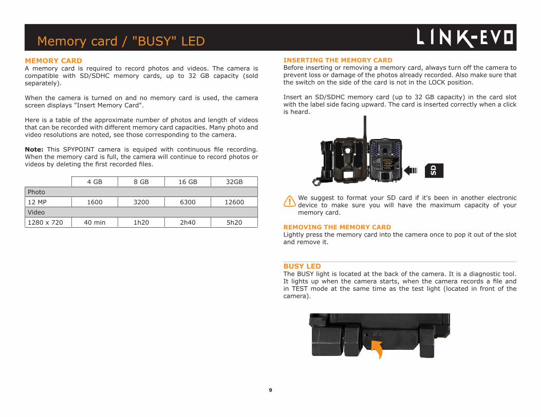
MEMORY CARDA memory card is required to record photos and videos. The camera is compatible with SD/SDHC memory cards, up to 32 GB capacity (sold separately).
When the camera is turned on and no memory card is used, the camera screen displays "Insert Memory Card".
Here is a table of the approximate number of photos and length of videos that can be recorded with different memory card capacities. Many photo and video resolutions are noted, see those corresponding to the camera.
Note: This SPYPOINT camera is equiped with continuous file recording. When the memory card is full, the camera will continue to record photos or videos by deleting the first recorded files.
4 GB 8 GB 16 GB 32GBPhoto12 MP 1600 3200 6300 12600Video1280 x 720 40 min 1h20 2h40 5h20
Memory card / "BUSY" LED
INSERTING THE MEMORY CARDBefore inserting or removing a memory card, always turn off the camera to prevent loss or damage of the photos already recorded. Also make sure that the switch on the side of the card is not in the LOCK position.
Insert an SD/SDHC memory card (up to 32 GB capacity) in the card slot with the label side facing upward. The card is inserted correctly when a click is heard.
We suggest to format your SD card if it's been in another electronic device to make sure you will have the maximum capacity of your memory card.
REMOVING THE MEMORY CARDLightly press the memory card into the camera once to pop it out of the slot and remove it.
BUSY LEDThe BUSY light is located at the back of the camera. It is a diagnostic tool. It lights up when the camera starts, when the camera records a file and in TEST mode at the same time as the test light (located in front of the camera).
10
START THE CAMERA
We suggest to format your SD card if it’s been in another electronic device to make sure you will have the maximum capacity of your memory card.
1. Turn the camera ONUse the ON/OFF switch to turn the camera ON.
2. All lights flashing - Searching for signalThe signal search can take a few minutes. If you only see 1 bar flashing, the network test was unsuccessful. Move outside or get near a window and re-start the camera a few times if needed, be to connected to the cell network.
3. Number of lights - signal strengthOnce the network test is completed, you will see the signal strength in signal bars. Note that the signal bars on a LINK-EVO might not be equal to your other cellular devices as there’s no industry standard and practice to label dBm values to a specific number of bars.
4. Red light flashing (30 s) - Installation delayThe test light in front of the camera will flash for 30 seconds to allow the user to leave the area without being photographed or recorded.
5. All lights OFF - Camera readyThe camera has updated its status in the LINK app with the latest informations. The camera is now ready to take pictures and transmit them to your LINK app upon the next synch. Synchs are set by default to every 4 hours starting at midnight.
INSTALL THE FREE SPYPOINT LINK APP
The SPYPOINT LINK App lets you connect and control your camera remotely using a smartphone or tablet. Features include viewing your camera status, pictures, full control of the camera settings and more.
Install the free App1. Make sure you have a data package with either your smartphone or tablet or a Wifi connection.2. To install the App, you can either: ● Get it on Google PlayTM (Google Play is a trademark of Google Inc) ● Download on the App StoreTM (App Store is a trademarks of Apple Inc.) 3. Search for the SPYPOINT LINK App from SPYPOINT.4. Install the App on your smartphone or tablet.
Run the SPYPOINT LINK APP
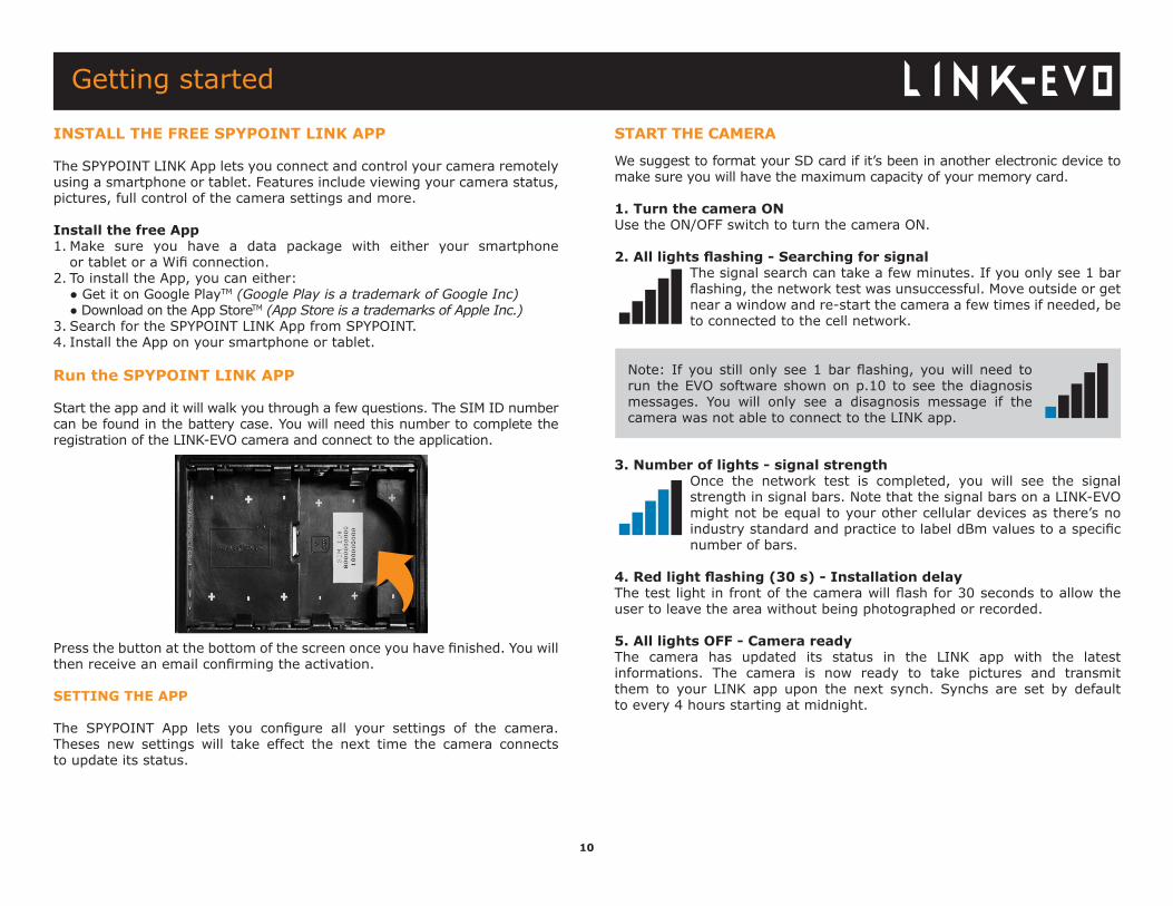
Start the app and it will walk you through a few questions. The SIM ID number can be found in the battery case. You will need this number to complete the registration of the LINK-EVO camera and connect to the application.
Press the button at the bottom of the screen once you have finished. You will then receive an email confirming the activation.
SETTING THE APP
The SPYPOINT App lets you configure all your settings of the camera. Theses new settings will take effect the next time the camera connects to update its status.
Getting started
Note: If you still only see 1 bar flashing, you will need to run the EVO software shown on p.10 to see the diagnosis messages. You will only see a disagnosis message if the camera was not able to connect to the LINK app.
11
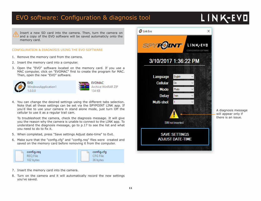
CONFIGURATION & DIAGNOSIS USING THE EVO SOFTWARE
1. Remove the memory card from the camera.
2. Insert the memory card into a computer.
3. Open the "EVO" software located on the memory card. If you use a MAC computer, click on "EVOMAC" first to create the program for MAC. Then, open the new "EVO" software.
4. You can change the desired settings using the different tabs selection. Note that all these settings can be set via the SPYPOINT LINK app. If you'd like to use your camera in stand alone mode, just turn Off the cellular to use it as a regular trail cam.
To troubleshoot the camera, check the diagnosis message. It will give you the reason why the camera is unable to connect to the LINK app. To understand the diagnosis message, go to p.17 to see the list and what you need to do to fix it.
5. When completed, press "Save settings Adjust date-time" to Exit.
6. Make sure that the "config.cfg" and "config.req" files were created and saved on the memory card before removing it from the computer.
7. Insert the memory card into the camera.
8. Turn on the camera and it will automatically record the new settings you've saved.
Insert a new SD card into the camera. Then, turn the camera on and a copy of the EVO software will be saved automaticly onto the memory card.
A diagnosis message will appear only if there is an issue.
EVO software: Configuration & diagnosis tool
12
MODIFY YOUR PROFILE INFORMATIONModify your profile like Password, Name, Address, Phone number & more.
STATUSSee general informations of the camera.
LEVELSSee your camera Signal strengh, Battery level, SD card space and more.
GENERAL INFORMATIONSee your camera Model, Version, Last communication, Nb of pictures this month, Temperature, Last movement and Battery type.
SETTINGSModify the settings, the synchronisation frequency & others
BASIC SETTINGSMode - PHOTOSet Delay, Multi-shot & Camera name.
Mode - TIME LAPSESet Interval.
Mode - VIDEOSet Delay, Photo first & Video length.
SYNCHRONISATION SETTINGSSet Cellular transmission, First sync time & Sync frequency.
ADVANCED OPTIONSSet the Date format, Temp. unit., Night mode and more.
PHOTOSSee your pictures by date, month and years. It also lets you share or download your photos.
• Scroll up or down to view your photos by date. • Click on a photo to select it and see it larger. □ Swipe left to see previous photo or right for the next one. □ Click on the arrow at the top right of the screen to share the photo on facebook. □ Leave your finger on a photo to be able to delete it from the App. □ Swipe up or down to return to the PHOTOS tab & refresh the screen.
WIRELESS SETUP OF THE LINK CAMERANote that any modificactions of the settings through the app will carry over to the camera at the time of its next synch. All the settings in the App are the same one as in the camera. If you're not sure what a setting does, please refer to the next section.
ACCOUNTSelect the data plan and modify your profile informations.
DATA PLANSelect your data plan from Annual, Annual+ or Hunting (3 Months). If you choose not to activate a plan, note that you’ll still be able to transmit/receive pictures with our FREE monthly plan. It will allow you to transmit/receive up to 100 photos per month with a photo history of the last 7 days.
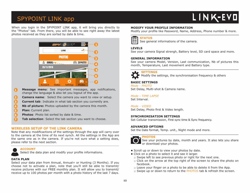
SPYPOINT LINK appWhen you login in the SPYPOINT LINK app, it will bring you directly to the "Photos" tab. From there, you will be able to see right away the latest photos received as they are sorted by date & time.
7
1
2
4
3
Message menu: See important messages, app notifications, change the language & also let you logout of the app. Camera name: Select the camera you want to view or setup. Current tab: Indicate in what tab section you currently are. Nb of picture: Photos uploaded by the camera this month. Plan: Current plan. Photos: Photo list sorted by date & time. Tab selection: Select the tab section you want to choose.
1
3
5
2
4
67
5
6
13
BASIC SETTINGS
PHOTO MODE
Delay:(Instant/10s/1m/3m/5m/10m/15m/30m)
Allows the user to choose the time interval between each detection before the camera records the next photo. A longer delay minimizes the number of photos taken and maximizes the battery life. A shorter delay maximizes the number of photos taken but requires more battery power. A shorter delay interval is recommended when the camera is used for security purposes.
Multi-shot:(1/2 consecutive shots)
Takes up to 2 consecutive shots at each detection, with a 5-second delay between each photo. This option allows the user to get up to 2 photos when the camera is in PHOTO mode.
Camera name
Allows to identify the camera clearly. This option is particularly useful for users with more than one camera.
TIME LAPSE MODE
Interval:(From 3m to 24h)
Allows the camera to take photos at regular preset intervals. For example, if "5m" is selected in the TIME LAPSE mode, the camera takes a photo every 5 minutes even if there is no detection. This option allows the user to obtain photos of game outside the detection range of the camera.
Note: The TIME LAPSE mode only applies for photos, not videos. When the TIME LAPSE mode is selected, the DELAY option and the MULTI-SHOT mode are disabled.
VIDEO MODE
Delay:(Instant/10s/1m/3m/5m/10m/15m/30m))
Allows the user to choose the time interval between each detection before the camera records the next video.
Photo first
When this option is enabled, a photo is taken immediately before each video.
Note: The file name of the photo corresponds to the digit before the video file name. For example, if the name of the photo is PICT001.JPG, the name of the video will be VID001.AVI.
Video length:(10s/30s/60s/90s)
Allows the user to select the duration of the recording when the camera is set in VIDEO mode.
SPYPOINT LINK app
14
Schedule:
Allows the user to set the period of operation of the camera for each day of the week. The start and stop time are the hours during which the camera is in action and can record pictures or videos. For an activation of 24 hours, the same start and stop time must be entered
Note: The hours can be recorded over a 12 or 24 hours period. Refer to the «Time format» option.
OTHER OPTION SETTINGReport stolen:Allows the user to report that his camera has being stolen.
SYNCHRONISATION SETTINGSFirst sync time: Allows the user to choose at what time of the day the camera communicates for the first time.
Synchronisation frequency:Allows the user to choose the number of synchronizations that the camera performs in a day to send pictures.
ADVANCED OPTION SETTING
Date format:(MDY, DMY)
Allows the user to set the date as Month/Day/Year or as Day/Month/Year.
Temp. units:(°C/°F)
Allows the user to select the temperature display.
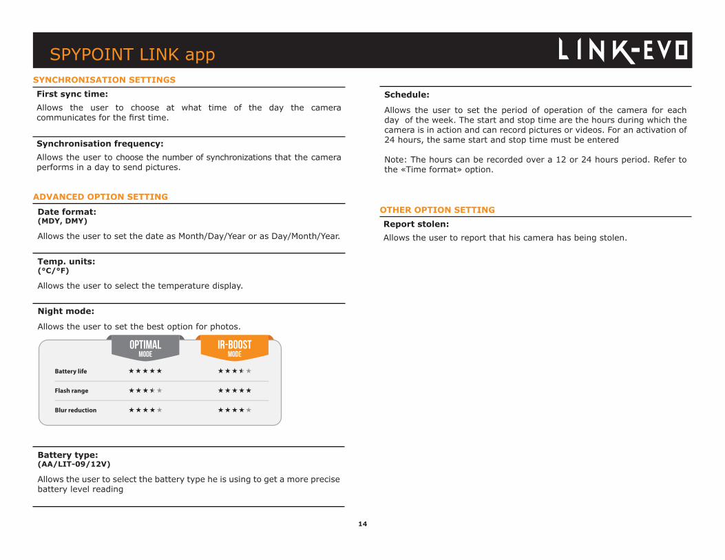
Night mode:
Allows the user to set the best option for photos.
Battery type:(AA/LIT-09/12V)
Allows the user to select the battery type he is using to get a more precise battery level reading
illumination modes comparison* (Night modes)
* Available for photos only
optimalMODE
IR-boostMODE
Blur reduction
Battery life
Flash range
SPYPOINT LINK app
15
Installation & Mounting bracketINSTALLATIONRecommended installation height:The camera should be installed at the same height as the animal’s mid-body.
Ideal installation for quality pictures & videos:The targeted animal should be 25 feet / 7.5m away from the camera for a better field of view.
To get brighter pictures at night , you should have elements in the background to reflect back the IR flash to the camera. (e.g. Trees or fence)
Make sure the front of the camera is free of any obstructions. The area of installation should be cleared from branches or bushes. These could be responsible for triggering false detections when combined with heat, reflec-tions and/or wind.
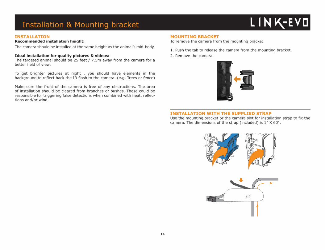
MOUNTING BRACKETTo remove the camera from the mounting bracket:
1. Push the tab to release the camera from the mounting bracket.2. Remove the camera.
INSTALLATION WITH THE SUPPLIED STRAPUse the mounting bracket or the camera slot for installation strap to fix the camera. The dimensions of the strap (included) is 1" X 60".
16
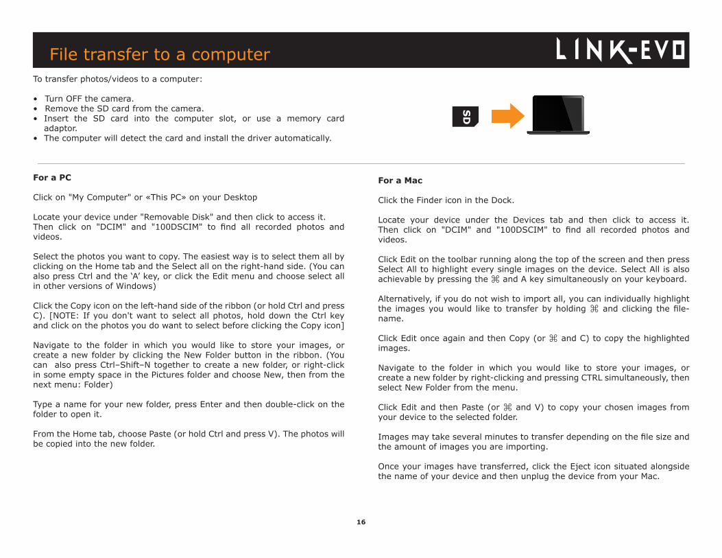
To transfer photos/videos to a computer:
• Turn OFF the camera.• Remove the SD card from the camera.• Insert the SD card into the computer slot, or use a memory card adaptor.• The computer will detect the card and install the driver automatically.
For a PC
Click on "My Computer" or «This PC» on your Desktop
Locate your device under "Removable Disk" and then click to access it. Then click on "DCIM" and "100DSCIM" to find all recorded photos and videos.
Select the photos you want to copy. The easiest way is to select them all by clicking on the Home tab and the Select all on the right-hand side. (You can also press Ctrl and the ‘A’ key, or click the Edit menu and choose select all in other versions of Windows)
Click the Copy icon on the left-hand side of the ribbon (or hold Ctrl and press C). [NOTE: If you don't want to select all photos, hold down the Ctrl key and click on the photos you do want to select before clicking the Copy icon]
Navigate to the folder in which you would like to store your images, or create a new folder by clicking the New Folder button in the ribbon. (You can also press Ctrl–Shift–N together to create a new folder, or right-click in some empty space in the Pictures folder and choose New, then from the next menu: Folder)
Type a name for your new folder, press Enter and then double-click on the folder to open it.
From the Home tab, choose Paste (or hold Ctrl and press V). The photos will be copied into the new folder.
File transfer to a computer
For a Mac
Click the Finder icon in the Dock.
Locate your device under the Devices tab and then click to access it. Then click on "DCIM" and "100DSCIM" to find all recorded photos and videos.
Click Edit on the toolbar running along the top of the screen and then press Select All to highlight every single images on the device. Select All is also achievable by pressing the ⌘ and A key simultaneously on your keyboard.
Alternatively, if you do not wish to import all, you can individually highlight the images you would like to transfer by holding ⌘ and clicking the file-name.
Click Edit once again and then Copy (or ⌘ and C) to copy the highlighted images.
Navigate to the folder in which you would like to store your images, or create a new folder by right-clicking and pressing CTRL simultaneously, then select New Folder from the menu.
Click Edit and then Paste (or ⌘ and V) to copy your chosen images from your device to the selected folder.
Images may take several minutes to transfer depending on the file size and the amount of images you are importing.
Once your images have transferred, click the Eject icon situated alongside the name of your device and then unplug the device from your Mac.
17
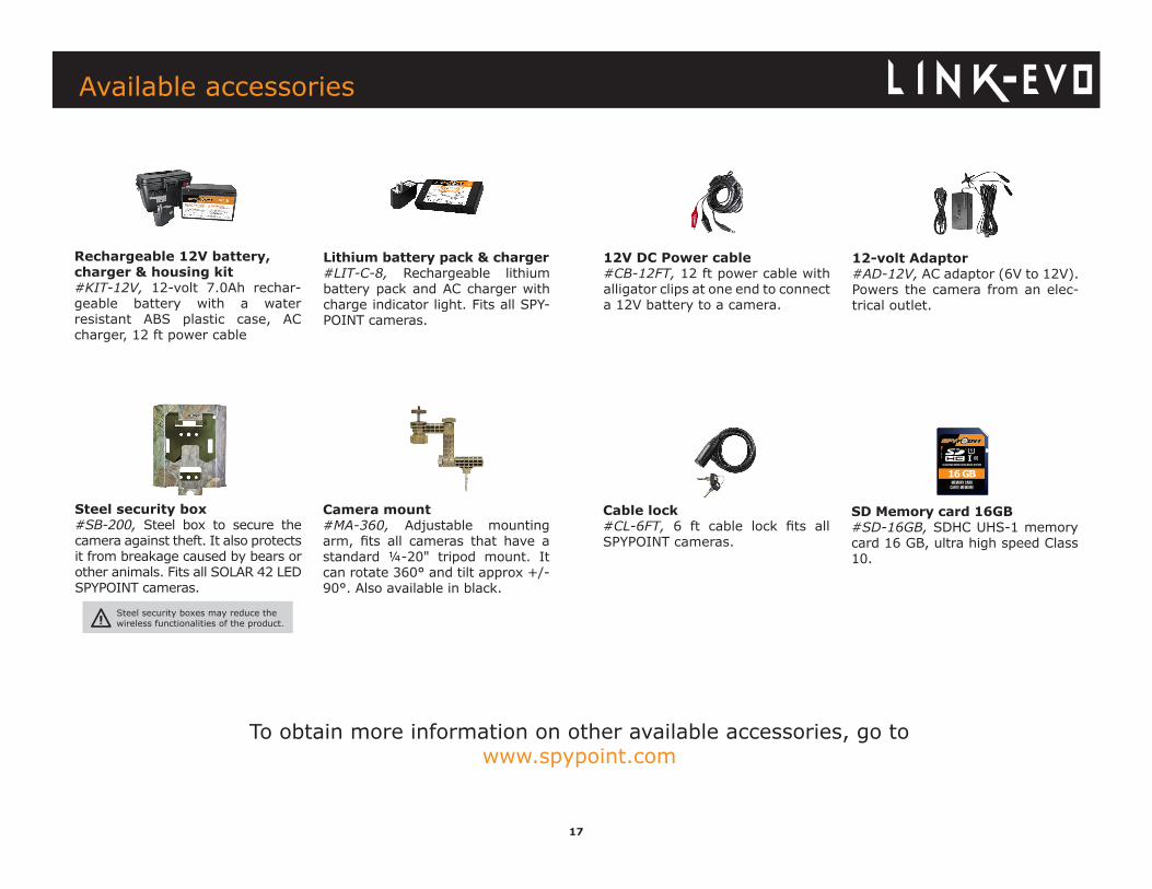
12-volt Adaptor #AD-12V, AC adaptor (6V to 12V). Powers the camera from an elec-trical outlet.
12V DC Power cable#CB-12FT, 12 ft power cable with alligator clips at one end to connect a 12V battery to a camera.
Rechargeable 12V battery, charger & housing kit#KIT-12V, 12-volt 7.0Ah rechar-geable battery with a water resistant ABS plastic case, AC charger, 12 ft power cable
Lithium battery pack & charger#LIT-C-8, Rechargeable lithium battery pack and AC charger with charge indicator light. Fits all SPY-POINT cameras.
Memory CardCarte Mémoire
ULTRA HIGH SPEED/ULTRA HAUTE VITESSE
16 GB
SD Memory card 16GB#SD-16GB, SDHC UHS-1 memory card 16 GB, ultra high speed Class 10.
Available accessories
Cable lock#CL-6FT, 6 ft cable lock fits all SPYPOINT cameras.
Camera mount#MA-360, Adjustable mounting arm, fits all cameras that have a standard ¼-20" tripod mount. It can rotate 360° and tilt approx +/-90°. Also available in black.
Steel security box#SB-200, Steel box to secure the camera against theft. It also protects it from breakage caused by bears or other animals. Fits all SOLAR 42 LED SPYPOINT cameras.
To obtain more information on other available accessories, go to www.spypoint.com
Steel security boxes may reduce the wireless functionalities of the product.
18
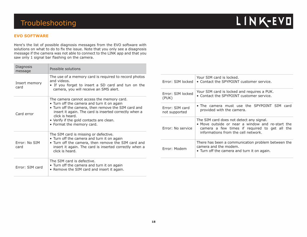
Error: SIM lockedYour SIM card is locked. • Contact the SPYPOINT customer service.
Error: SIM locked (PUK)
Your SIM card is locked and requires a PUK.• Contact the SPYPOINT customer service.
Error: SIM card not supported
• The camera must use the SPYPOINT SIM card provided with the camera.
Error: No service
The SIM card does not detect any signal.• Move outside or near a window and re-start the camera a few times if required to get all the informations from the cell network.
Error: Modem
There has been a communication problem between the camera and the modem.• Turn off the camera and turn it on again.
Diagnosis message Possible solutions
Insert memory card
The use of a memory card is required to record photos and videos.• If you forget to insert a SD card and tun on the camera, you will receive an SMS alert.
Card error
The camera cannot access the memory card.• Turn off the camera and turn it on again• Turn off the camera, then remove the SIM card and insert it again. The card is inserted correctly when a click is heard.
• Verify if the gold contacts are clean.• Format the memory card.
Error: No SIM card
The SIM card is missing or defective.• Turn off the camera and turn it on again• Turn off the camera, then remove the SIM card and insert it again. The card is inserted correctly when a click is heard.
Error: SIM card
The SIM card is defective.• Turn off the camera and turn it on again• Remove the SIM card and insert it again.
TroubleshootingEVO SOFTWARE
Here's the list of possible diagnosis messages from the EVO software with solutions on what to do to fix the issue. Note that you only see a disagnosis message if the camera was not able to connect to the LINK app and that you saw only 1 signal bar flashing on the camera.
19
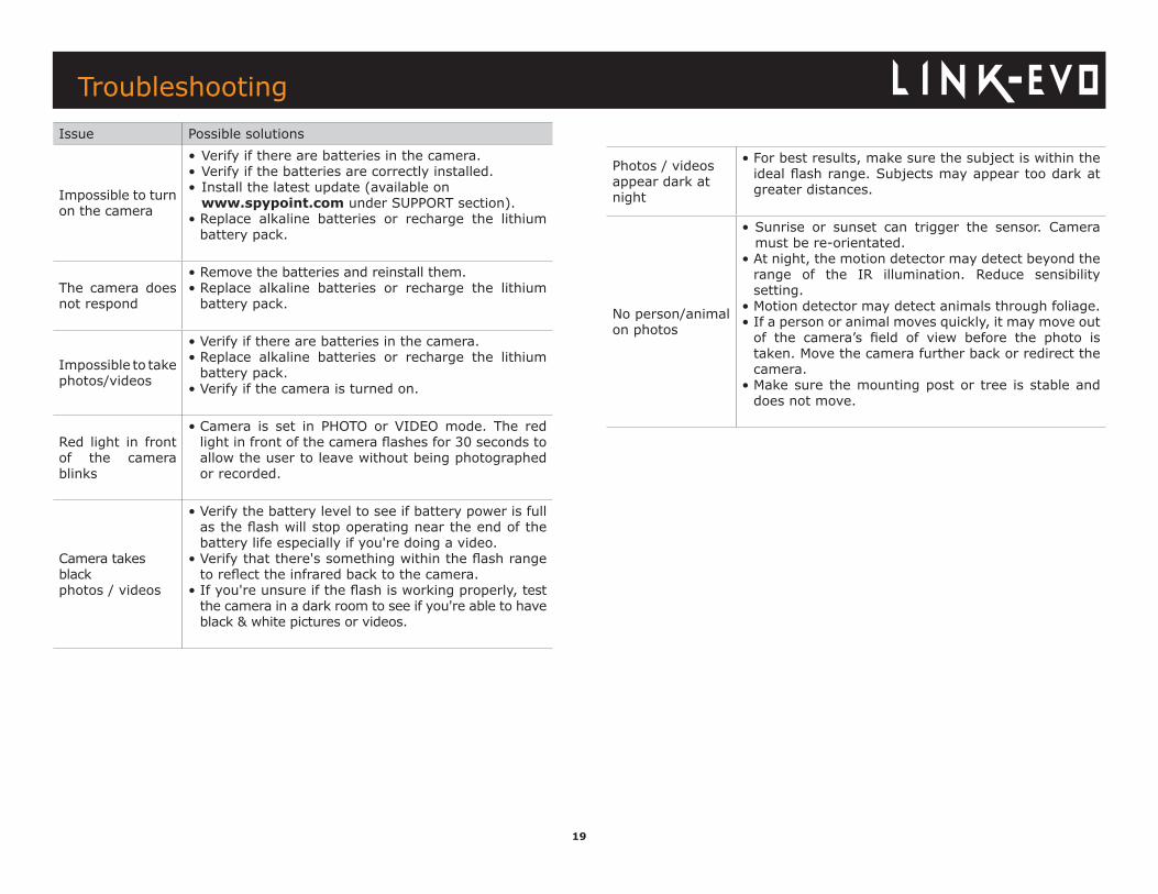
Issue Possible solutions
Impossible to turn on the camera
• Verify if there are batteries in the camera.• Verify if the batteries are correctly installed.• Install the latest update (available on www.spypoint.com under SUPPORT section).• Replace alkaline batteries or recharge the lithium battery pack.
The camera does not respond
• Remove the batteries and reinstall them.• Replace alkaline batteries or recharge the lithium battery pack.
Impossible to take photos/videos
• Verify if there are batteries in the camera.• Replace alkaline batteries or recharge the lithium battery pack.• Verify if the camera is turned on.
Red light in front of the camera blinks
• Camera is set in PHOTO or VIDEO mode. The red light in front of the camera flashes for 30 seconds to allow the user to leave without being photographed or recorded.
Camera takes black photos / videos
• Verify the battery level to see if battery power is full as the flash will stop operating near the end of the battery life especially if you're doing a video.• Verify that there's something within the flash range to reflect the infrared back to the camera.• If you're unsure if the flash is working properly, test the camera in a dark room to see if you're able to have black & white pictures or videos.
Photos / videos appear dark at night
• For best results, make sure the subject is within the ideal flash range. Subjects may appear too dark at greater distances.
No person/animal on photos
• Sunrise or sunset can trigger the sensor. Camera must be re-orientated.• At night, the motion detector may detect beyond the range of the IR illumination. Reduce sensibility setting.• Motion detector may detect animals through foliage.• If a person or animal moves quickly, it may move out of the camera’s field of view before the photo is taken. Move the camera further back or redirect the camera.• Make sure the mounting post or tree is stable and does not move.
Troubleshooting

20
Warranty & Repair
This SPYPOINT product designed by GG Telecom, is covered by a two (2) year limited warranty on material and workmanship starting from the original date of purchase. The electronic sales receipt is the client’s proof of purchase and must be presented if warranty service is needed. This warranty will be honored in the country of purchase only.
This GG Telecom warranty does not apply to: (a) consumable parts, including but not limited to batteries, which performance is designed to decrease over the course of time; (b) damage caused by misuse, use with another product, neglect, accidents, liquid contact, fire, earthquake or any other external cause; (c) GG Telecom products that have been purchased online from an unauthorized dealer; (d) products that have had any modification or tampering; (e) cosmetic damage including but not limited to scratches and broken plastic; (f) damage caused by operating the GG Telecom product outside of GG Telecom’s recommendations.
INSTRUCTIONS FOR REPAIR SERVICE
GG Telecom will repair the product or replace it at its discretion with an equivalent product without charge if covered by the warranty described previously. The shipping fees for an item sent will be assumed by the customer. GG Telecom will then pay for the return of the product covered by the warranty.
For a product not covered by the warranty, the repair will be subject to a reasonable charge and the customer will also assume all shipping costs.
IMPORTANT: Under no circumstances will GG Telecom accept returned products without a RMA number. (Return Material Authorization) It is essential to contact GG Telecom before making a return.
1. Before sending a product for repair, please contact GG Telecom technical support team at 1-888-779-7646 or [email protected] as most issues can be solved over the phone or by email.2. If a product needs to be sent, a RMA number will be given to authorize the return of the product and for future reference. 3. The original receipt or a copy must be sent along with the package.4. The RMA number must be written on the outside of the package and sent to:
CANADA United States GG Telecom GG Telecom 330 de la Jacques-Cartier 3000 Gannett Avenue, Suite 2 Victoriaville, QC Des Moines, Iowa 50321, USA G6T 1Y3
The customer is liable for loss or damage to the product that may occur during the transport to GG Telecom. We recommend the use of a traceable method of shipping to ensure protection.
WWW.SPYPOINT.COM
Sit back, relax & know you’re covered
21
FCC REGULATIONSFCC Part l5This equipment has been tested and found to comply with the limits for a Class B digital device, pursuant to Part 15 of the Federal
Communications Commission (FCC) rules. These limits are designed to provide reasonable protection against harmful interference in a residential installation. This equipment generates, uses and can radiate radio frequen-cy energy and, if not installed and used in accordance with the instructions, may cause harmful interference to radio communications. However, there is no guarantee that interference will not occur in a particular installation. If this equipment does cause harmful interference to radio or television reception, which can be determined by turning the equipment off and on, the user is encouraged to try to correct the interference by one or more of the following measures: • Reorient or relocate the receiving antenna. • Increase the separation between the equipment and receiver. • Connect the equipment into an outlet on a circuit different from that to which the receiver is connected. • Consult the dealer or an experienced radio/TV technician for help.Changes or modifications to this equipment not expressly approved by the party responsible for compliance could void the user’s authority to operate the equipment.This device complies with Part 15 of the FCC rules. Operation is subject to the following two conditions: (1) this device may not cause harmful interference, and (2) this device must accept any interference received, including interference that may cause undesired operation.
Regulations