Embed Size (px)
Citation preview
Virtavia SP-5B Marlin Manual Version 1.0
0
SP-5B (P5M-2) Marlin
USER MANUAL
Virtavia SP-5B Marlin Manual Version 1.0
1
Introduction
Initiated in July, 1946 as a successor to the PBM Mariner, the XP5M-
1(Model 237) Marlin was based on a new hull design and first flew on
May 4, 1948. Production aircraft were built in two versions. The P5M-1
(SP-5A) incorporated a standard tail configuration, while the P5M-2 (SP-
5B) was modified to carry a T-type tailplane. Production began in Dec.
1951 with an eventual 160 P5M-1s being delivered to the Navy. This
was followed by 117 P5M-2s. The last was delivered in Dec. 1960. All
aircraft carried an APS-44A radar radome in the nose and were armed
with homing torpedos and depth charges carried in bomb bays aft of the
engines. In 1962 the Marlin was redesignated SP-5. Many were
retrofitted with APS-80 search radar, ASQ-8 magnetic anomaly
detectors and provisions for two Mk.43 torpedoes or four 2,025 lb. Mk.39
mines. During the Vietnam War, SP-5s played a significant role in
coastal patrol, tracking enemy supply movements from North to South.
The last SP-5 was retired on November 6, 1967.
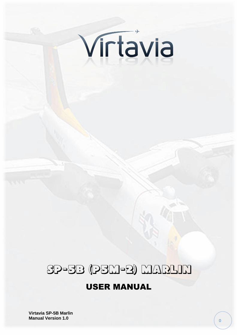
The Virtavia SP-5B Marlin is a fully 'native' FSX release, including the
now standard technologies such as self shadowing, bloom effects, and
bump mapping.
Virtavia SP-5B Marlin Manual Version 1.0
2
Installation
An easy installation is provided by way of an auto-installer, the Marlin
will be installed to the default FSX folder structure. The install path can
be edited in the Installer Dialogue to reflect a custom installation path
such as E:Games\FSX\ for example.
Extras such as this manual will be installed into FSX/Virtavia. A start
menu entry will also be made, with an uninstaller should you ever wish
to remove the product.
Please see the ‘Package Contents’ section for more details on what is
included in this package.
Credits
Exterior model – Virtavia
Textures – Dan Dunn of Pixl Creative
Interior model - Virtavia
Gauges – Herbert Pralle/Virtavia
Animation coding – Virtavia
Flight Dynamics - Mitch London
Engine Sounds - Virtavia
Manual - Virtavia
Testing - Frank Safranek, Mitch London, Virtavia
Recommended reading : Naval Fighters 74, by Capt. Richard Hoffman –
USN (Ret.)
ISBN 0-942612-74-4
Virtavia SP-5B Marlin Manual Version 1.0
3
Support
Should you experience difficulties or require extra information about the
Virtavia SP-5B Marlin, please e-mail our technical support on
Copyright Information
Please help us provide you with more top quality flight simulator models
like this one by NOT using pirate copies. The flight simulation industry is
not very profitable and we need all the help we can get. Please - help us
grow by buying a legitimate copy.
These files may not be copied (other than for backup purposes),
transmitted or passed to third parties or altered in any way without the
prior permission of the publisher.
The source code for this product is closed. No modifications or reverse
engineering may be carried out without prior consent from Virtavia.
All rights reserved – copyright Virtavia Pty Ltd 2014
Virtavia SP-5B Marlin Manual Version 1.0
4
Package Contents
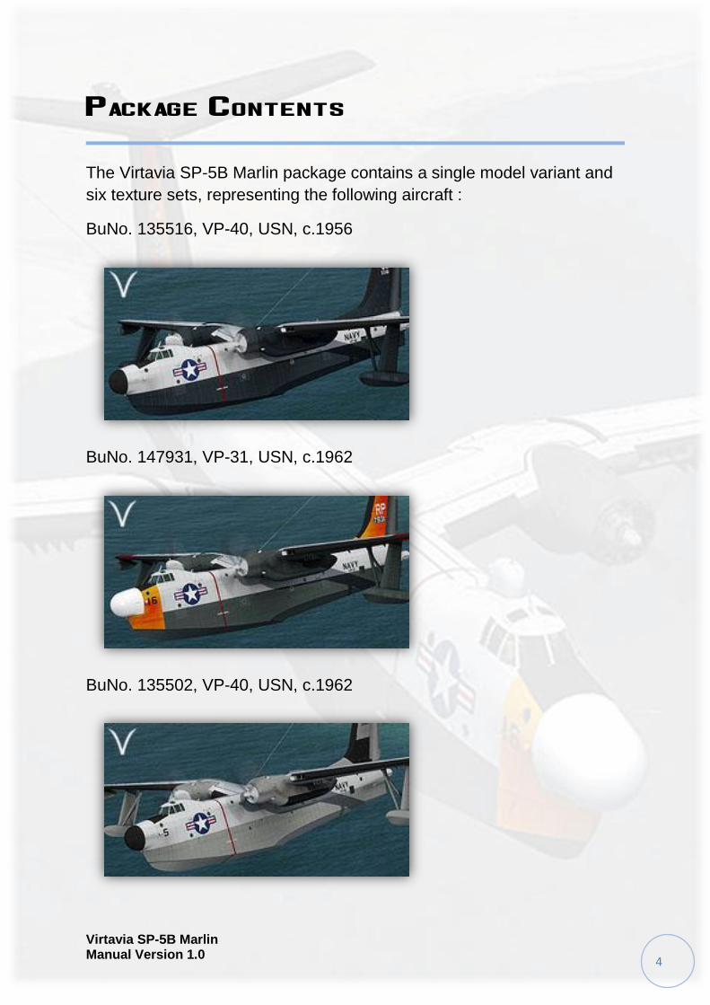
The Virtavia SP-5B Marlin package contains a single model variant and
six texture sets, representing the following aircraft :
BuNo. 135516, VP-40, USN, c.1956
BuNo. 147931, VP-31, USN, c.1962
BuNo. 135502, VP-40, USN, c.1962
Virtavia SP-5B Marlin Manual Version 1.0
5
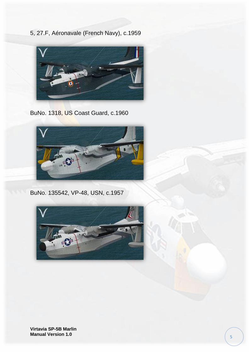
5, 27.F, Aéronavale (French Navy), c.1959
BuNo. 1318, US Coast Guard, c.1960
BuNo. 135542, VP-48, USN, c.1957
Virtavia SP-5B Marlin Manual Version 1.0
6
Exterior Model
The exterior model has all the usual animations such as ailerons,
elevators, cowl flaps and landing flaps. There are no speedbrakes fitted
to the Marlin although small spoilerons are used on each upper wing to
assist the ailerons.
Hydro Flaps
The Marlin is unusual as it has ‘Hydro Flaps’ at the extreme rear end of
the hull. These speedbrake-type doors are used to help turn the aircraft
in the water. They act in the same way as a rudder. To see the Hydro
Flaps in action, they must first be enabled by using the red covered
switch on the rear of the center pedestal in the cockpit. They will activate
with rudder input, whether on the ground or in the water.
Engine Nacelle Doors
Each nacelle has a bomb bay area where there would normally be
landing gear on a conventional aircraft. These bays have the ability to
carry bombs, mines and depth charges, although in practice they were
usually left empty or carried an additional fuel tank. On the model, they
can be opened and closed using the tail hook command (ctrl-T, or
custom setting).
Exits
Shift-E : Crew entry doors (2), left side
Shift-E+2 : Crew entry doors, right side
Shift-E+3 : Cockpit roof hatch, left side
Shift-E+4 : Cockpit roof hatch, right side
Access steps
Not an animation as such, the steps will appear when the engines are
off, the left side exit(s) are open, AND the wingfold key has been
pressed. This is not assigned by default in FSX, so users may have to
assign a key. The F key is ideal for this task. Pressing the wingfold key a
Virtavia SP-5B Marlin Manual Version 1.0
7
second time will hide the steps, but be patient as there is a short delay
before the steps vanish.
Crew figures
The crew figures can be toggled using Ctrl-W.
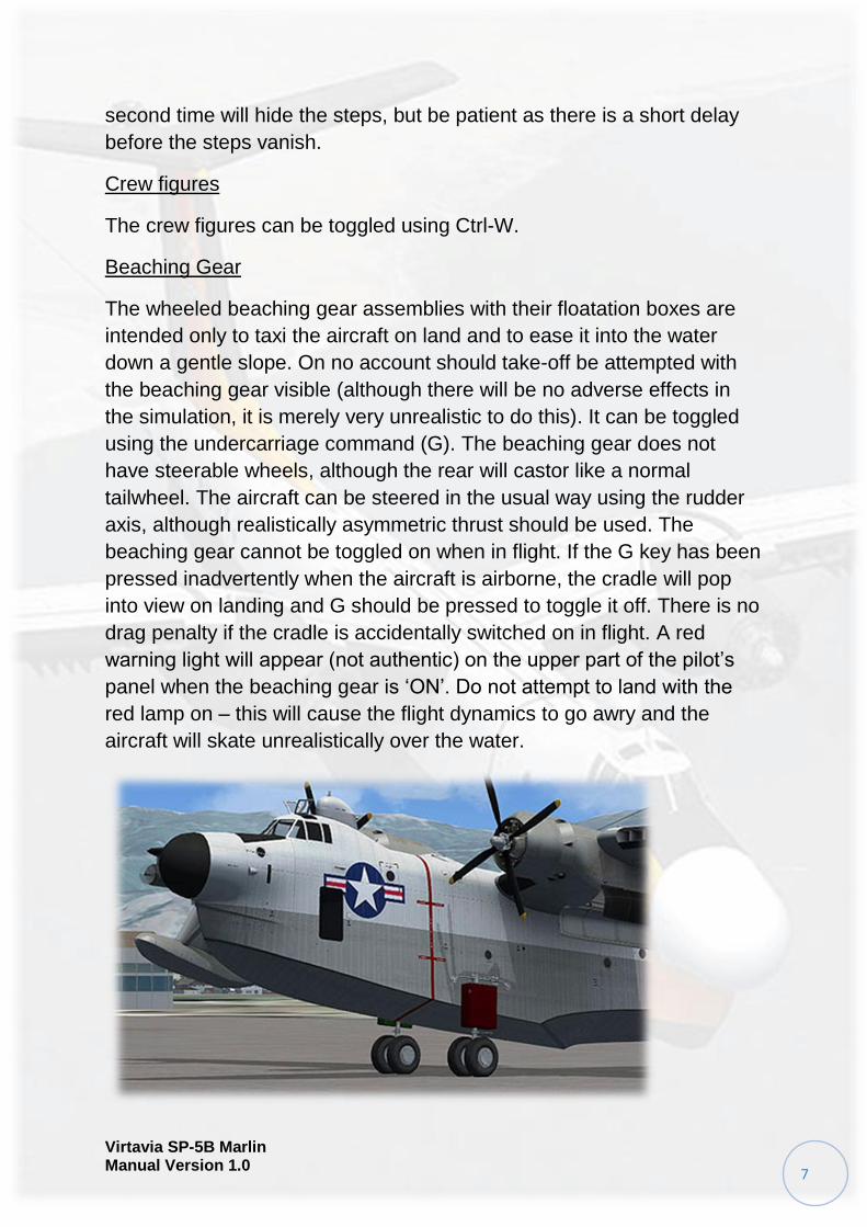
Beaching Gear
The wheeled beaching gear assemblies with their floatation boxes are
intended only to taxi the aircraft on land and to ease it into the water
down a gentle slope. On no account should take-off be attempted with
the beaching gear visible (although there will be no adverse effects in
the simulation, it is merely very unrealistic to do this). It can be toggled
using the undercarriage command (G). The beaching gear does not
have steerable wheels, although the rear will castor like a normal
tailwheel. The aircraft can be steered in the usual way using the rudder
axis, although realistically asymmetric thrust should be used. The
beaching gear cannot be toggled on when in flight. If the G key has been
pressed inadvertently when the aircraft is airborne, the cradle will pop
into view on landing and G should be pressed to toggle it off. There is no
drag penalty if the cradle is accidentally switched on in flight. A red
warning light will appear (not authentic) on the upper part of the pilot’s
panel when the beaching gear is ‘ON’. Do not attempt to land with the
red lamp on – this will cause the flight dynamics to go awry and the
aircraft will skate unrealistically over the water.
Virtavia SP-5B Marlin Manual Version 1.0
8
Propellers
The propeller blade pitch is animated through the range from fine to
coarse pitch. There is also a special animation for feathering the blades
in the event that an engine needs to be shut down in flight. This turns the
blades edge-on into the slipstream for minimum drag.
Propeller Pitch Settings
Minimum Pitch (high RPM)
Use Ctrl-F1 or mouse the Low/High RPM switches on the Prop Panel.
Note how the blades are ‘flat’ to the airflow, this is termed the minimum,
or ‘fine’ pitch.
Maximum Pitch (low RPM)
Use Ctrl-F4 or mouse the Low/High RPM switches on the Prop Panel.
The blades are now angled to the airflow and can ‘bite’. Always have the
props at this setting when starting or when at idle.
Feathered
Prop feathering is activated by pressing the large red button on the Fire
Control Panel. This will stop the engine and simultaneously turn the
blades to the minimum drag position.
Exterior Lighting
Pressing the L key will turn on all lights. You may however wish to turn
them on using the appropriate switches in the cockpit, as the L key also
turns the on navigation, landing lights, search light and both instrument
and flood lighting in the cockpit, which should ideally be switched
separately.
Shift-L will toggle the nav lights and the cockpit lights.
Crtl-L will toggle the landing lights.
Please refer to the cockpit section of this manual for information
regarding light switch location.
Virtavia SP-5B Marlin Manual Version 1.0
9
Alternative Viewpoints in FSX
There are several different ways of looking at the aircraft and the
cockpit, select these alternative views by right-clicking in an empty area
and picking the 'Aircraft' menu for external views and the 'Cockpit' menu
for views inside the cabin. It is possible to zoom and pan as normal in
these alternative views. Cycle though the available ones by pressing the
A key.
External View Options
It is possible to pan and zoom as normal in all external views.
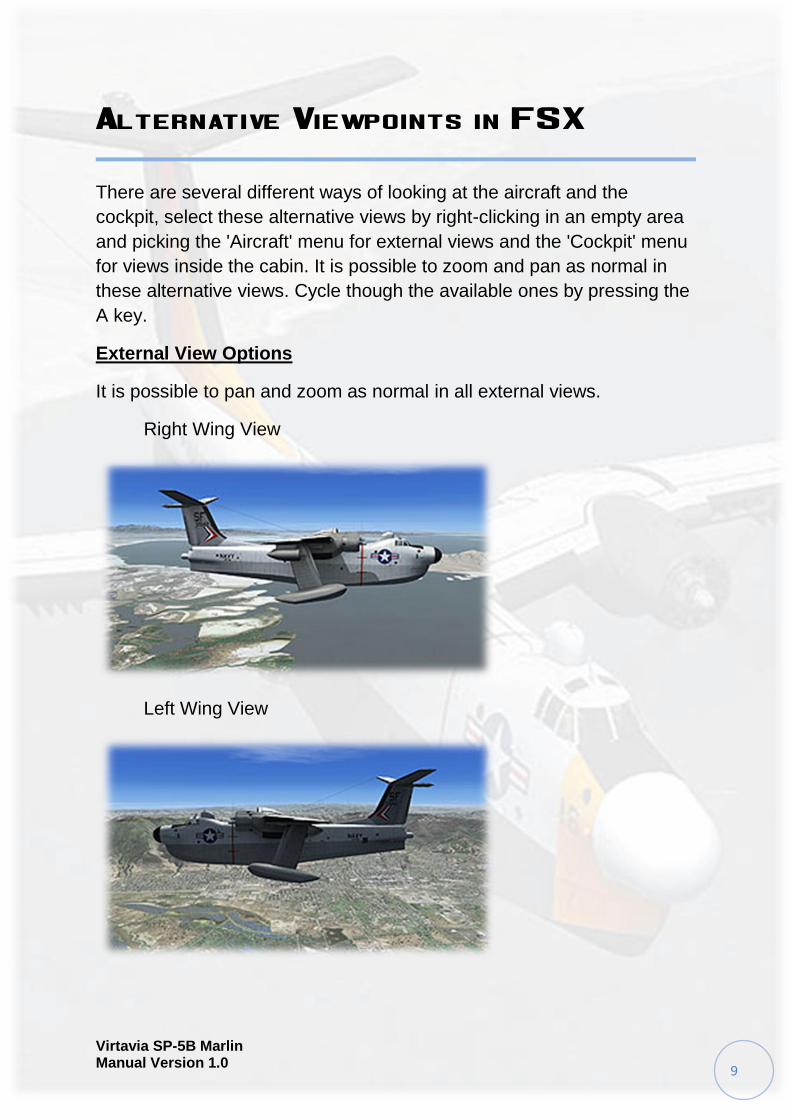
Right Wing View
Left Wing View
Virtavia SP-5B Marlin Manual Version 1.0
10
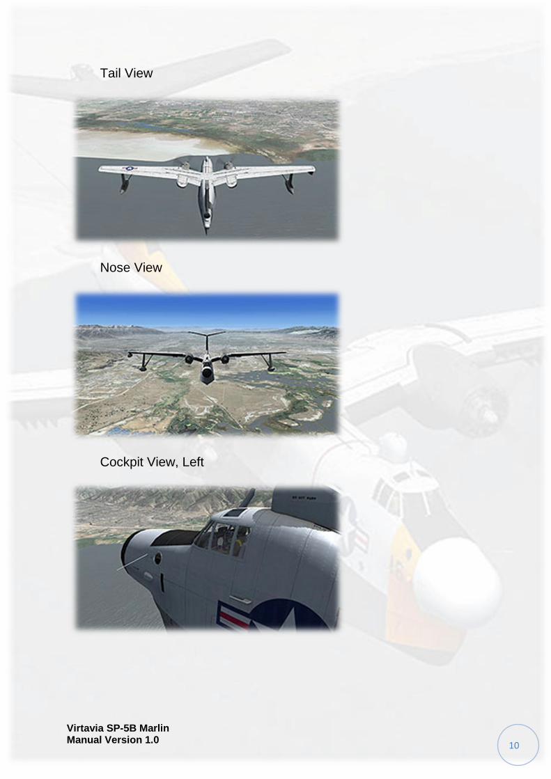
Tail View
Nose View
Cockpit View, Left
Virtavia SP-5B Marlin Manual Version 1.0
11
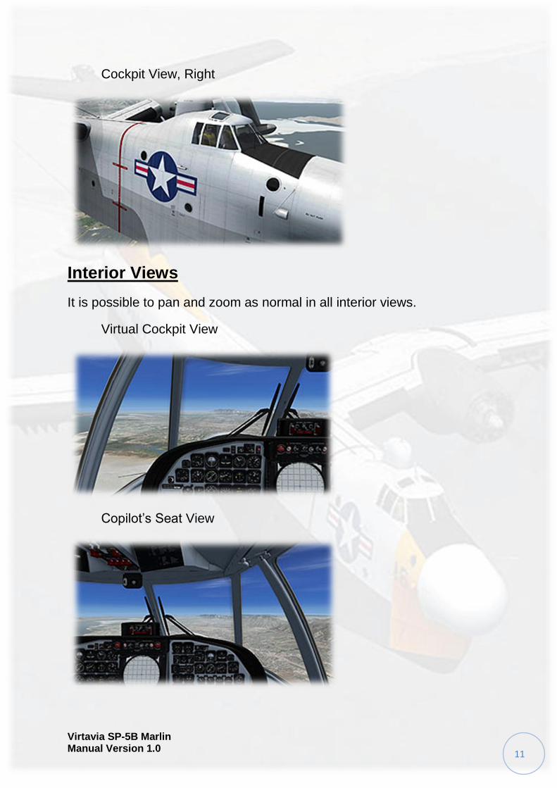
Cockpit View, Right
Interior Views
It is possible to pan and zoom as normal in all interior views.
Virtual Cockpit View
Copilot’s Seat View
Virtavia SP-5B Marlin Manual Version 1.0
12
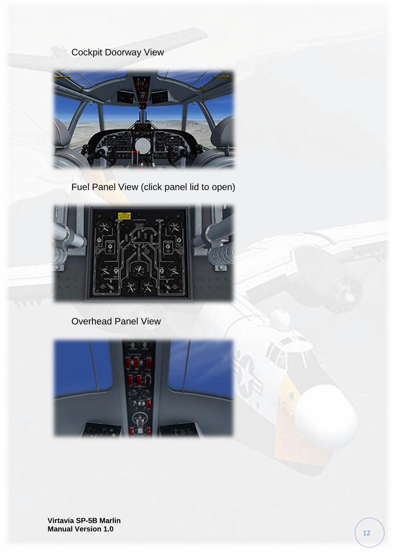
Cockpit Doorway View
Fuel Panel View (click panel lid to open)
Overhead Panel View
Virtavia SP-5B Marlin Manual Version 1.0
13
Moving Around the Cabin
Shift-Enter and Shift-Backspace : moves up and down
Ctrl-Shift-Enter and Ctrl-Shift-Backspace : moves side to side
Ctrl-Enter and Ctrl-Backspace : moves back and forwards
Virtavia SP-5B Marlin Manual Version 1.0
14
Virtual Cockpit Functions
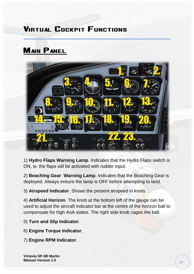
Main Panel
1) Hydro Flaps Warning Lamp. Indicates that the Hydro Flaps switch is
ON, ie. the flaps will be activated with rudder input.
2) Beaching Gear Warning Lamp. Indicates that the Beaching Gear is
deployed. Always ensure the lamp is OFF before attempting to land.
3) Airspeed Indicator. Shows the present airspeed in knots.
4) Artificial Horizon. The knob at the bottom left of the gauge can be
used to adjust the aircraft indicator bar at the centre of the horizon ball to
compensate for high AoA states. The right side knob cages the ball.
5) Turn and Slip Indicator.
6) Engine Torque Indicator.
7) Engine RPM Indicator.
Virtavia SP-5B Marlin Manual Version 1.0
15
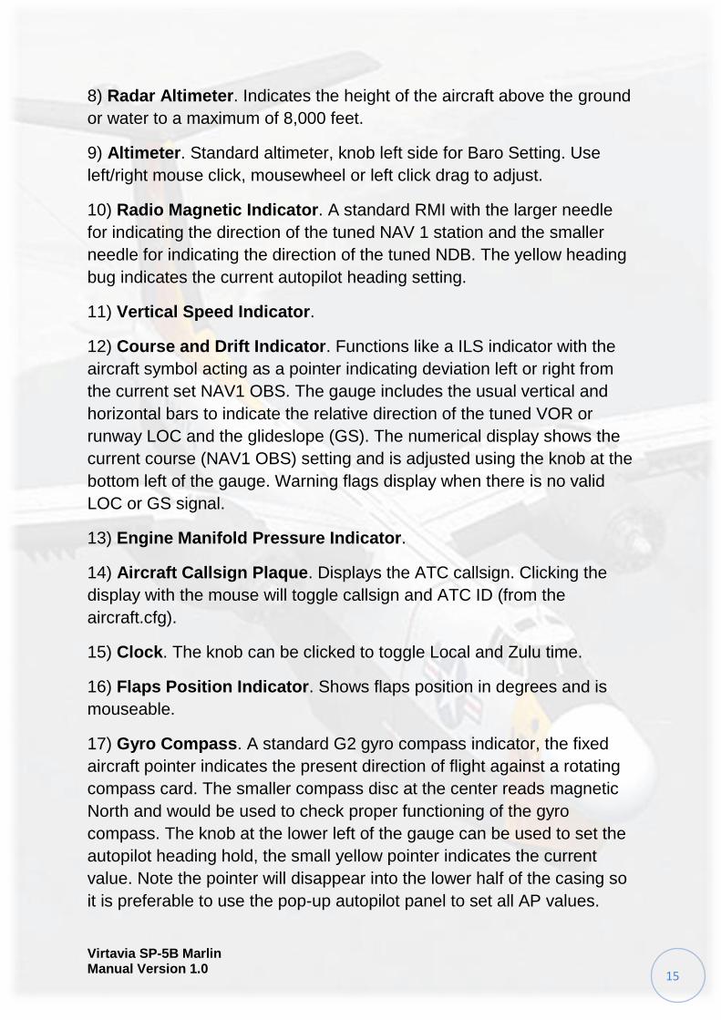
8) Radar Altimeter. Indicates the height of the aircraft above the ground
or water to a maximum of 8,000 feet.
9) Altimeter. Standard altimeter, knob left side for Baro Setting. Use
left/right mouse click, mousewheel or left click drag to adjust.
10) Radio Magnetic Indicator. A standard RMI with the larger needle
for indicating the direction of the tuned NAV 1 station and the smaller
needle for indicating the direction of the tuned NDB. The yellow heading
bug indicates the current autopilot heading setting.
11) Vertical Speed Indicator.
12) Course and Drift Indicator. Functions like a ILS indicator with the
aircraft symbol acting as a pointer indicating deviation left or right from
the current set NAV1 OBS. The gauge includes the usual vertical and
horizontal bars to indicate the relative direction of the tuned VOR or
runway LOC and the glideslope (GS). The numerical display shows the
current course (NAV1 OBS) setting and is adjusted using the knob at the
bottom left of the gauge. Warning flags display when there is no valid
LOC or GS signal.
13) Engine Manifold Pressure Indicator.
14) Aircraft Callsign Plaque. Displays the ATC callsign. Clicking the
display with the mouse will toggle callsign and ATC ID (from the
aircraft.cfg).
15) Clock. The knob can be clicked to toggle Local and Zulu time.
16) Flaps Position Indicator. Shows flaps position in degrees and is
mouseable.
17) Gyro Compass. A standard G2 gyro compass indicator, the fixed
aircraft pointer indicates the present direction of flight against a rotating
compass card. The smaller compass disc at the center reads magnetic
North and would be used to check proper functioning of the gyro
compass. The knob at the lower left of the gauge can be used to set the
autopilot heading hold, the small yellow pointer indicates the current
value. Note the pointer will disappear into the lower half of the casing so
it is preferable to use the pop-up autopilot panel to set all AP values.
Virtavia SP-5B Marlin Manual Version 1.0
16
18) Particle Indicator. Believed to be a Geiger Counter to detect alpha
particle radiation.
19) DME Indicator. Displays distance to the presently tuned NAV1
VOR/ILS in nautical miles.
20) Trim Indicator. This gauge is mousable and can be used to adjust
roll and yaw trim.
21) Sim Icons. Quick links to FSX functions for ATC, Radios, GPS,
Map, Kneeboard and Autopilot.
22) and 23) Hydraulic Pressure Indicators. Display the pressure of the
main hydraulics and controls boost systems.
Virtavia SP-5B Marlin Manual Version 1.0
17
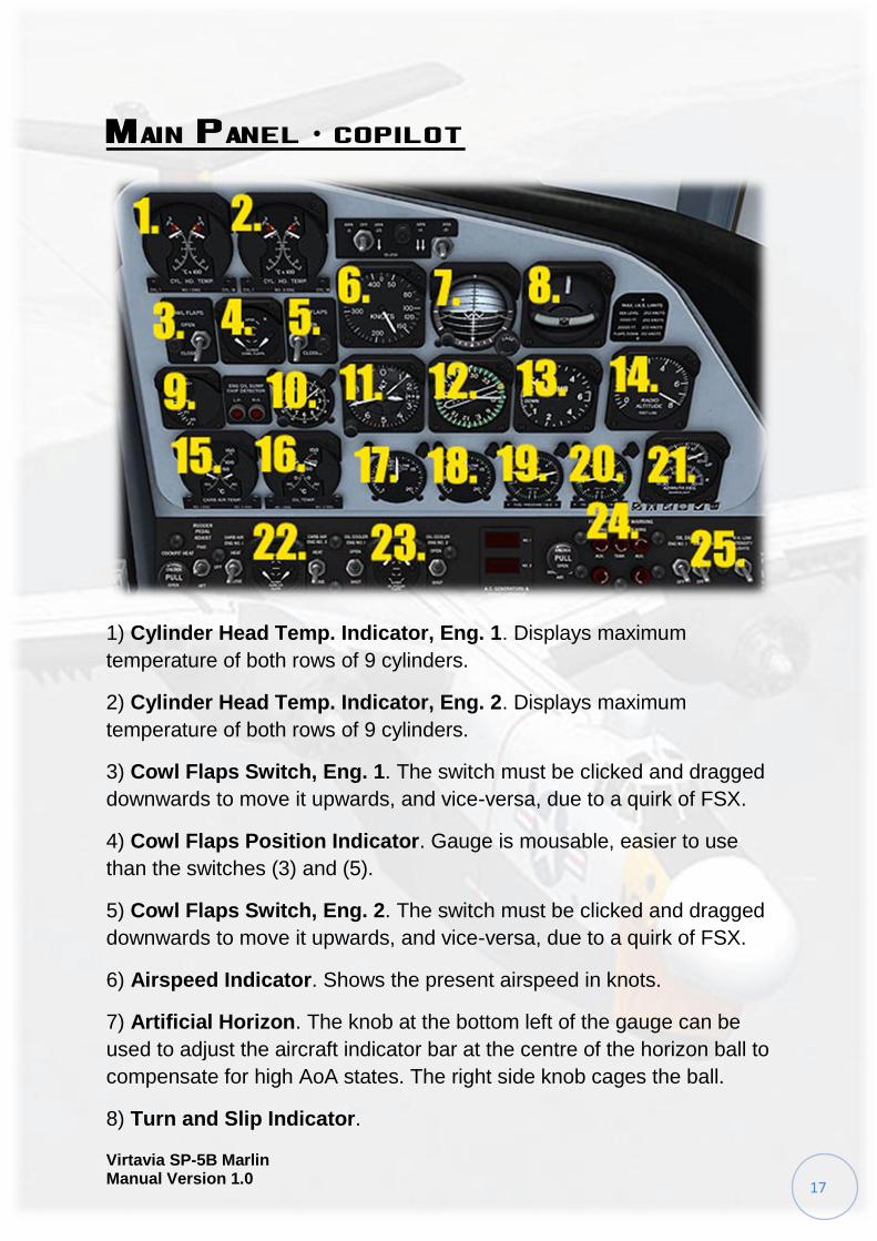
Main Panel - copilot
1) Cylinder Head Temp. Indicator, Eng. 1. Displays maximum
temperature of both rows of 9 cylinders.
2) Cylinder Head Temp. Indicator, Eng. 2. Displays maximum
temperature of both rows of 9 cylinders.
3) Cowl Flaps Switch, Eng. 1. The switch must be clicked and dragged
downwards to move it upwards, and vice-versa, due to a quirk of FSX.
4) Cowl Flaps Position Indicator. Gauge is mousable, easier to use
than the switches (3) and (5).
5) Cowl Flaps Switch, Eng. 2. The switch must be clicked and dragged
downwards to move it upwards, and vice-versa, due to a quirk of FSX.
6) Airspeed Indicator. Shows the present airspeed in knots.
7) Artificial Horizon. The knob at the bottom left of the gauge can be
used to adjust the aircraft indicator bar at the centre of the horizon ball to
compensate for high AoA states. The right side knob cages the ball.
8) Turn and Slip Indicator.
Virtavia SP-5B Marlin Manual Version 1.0
18
9) Outside Air Temp. Indicator. The mouse tooltip offer the
temperature in both Centigrade and Fahrenheit.
10) Clock. The knob can be clicked to toggle Local and Zulu time.
11) Altimeter. Standard altimeter, knob left side for Baro Setting. Use
left/right mouse click, mousewheel or left click drag to adjust.
12) Radio Magnetic Indicator. A standard RMI with the larger needle
for indicating the direction of the tuned NAV 1 station and the smaller
needle for indicating the direction of the tuned NDB. The yellow heading
bug indicates the current autopilot heading setting.
13) Vertical Speed Indicator.
14) Radar Altimeter. Indicates the height of the aircraft above the
ground or water to a maximum of 8,000 feet.
15) Carb. Air Temp. Indicator. Displays the carb. temperature for both
engines.
16) Oil Temp. Indicator. Displays the lubricating oil temperature for both
engines.
17) Fuel Flow Indicator, Eng. 1.
18) Fuel Flow Indicator, Eng. 2.
19) Fuel Pressure Indicator. Displays the fuel pressure for both
engines.
20) Oil Pressure Indicator. Displays the lubricating oil pressure for both
engines.
21) Searchlight Position Indicator. Indicates the pitch and yaw position
of the left wing-mounted searchlight. Not functional in the simulation.
22) Carb. Heat. Switches for each engine and a gauge. The gauge face
shows multiple positions but FSX only allows carb. heat ‘on’ or ‘off’.
23) Oil Cooler Flaps. Switches for each engine and a gauge. The
gauge face shows multiple positions but only ‘on’ or ‘off’ is used. The oil
cooler flaps are normally open (on). They are positioned behnd the
engine on top of the wing.
Virtavia SP-5B Marlin Manual Version 1.0
19
24) Sim Icons. Quick links to FSX functions for ATC, Radios, GPS,
Map, Kneeboard and Autopilot.
25) Panel Lights Switch. Toggles the lighting for the instruments and
panel descriptive text (not cabin flood lighting, which has a separate
switch on the pilot’s left console).
Center Panel
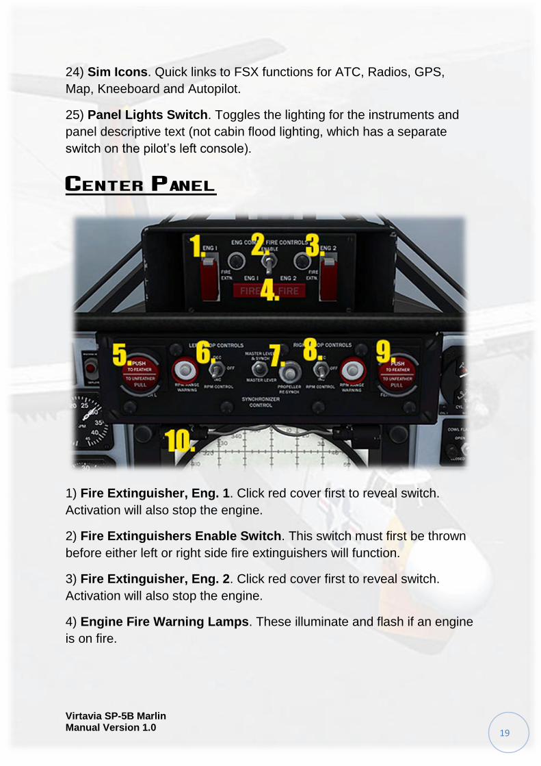
1) Fire Extinguisher, Eng. 1. Click red cover first to reveal switch.
Activation will also stop the engine.
2) Fire Extinguishers Enable Switch. This switch must first be thrown
before either left or right side fire extinguishers will function.
3) Fire Extinguisher, Eng. 2. Click red cover first to reveal switch.
Activation will also stop the engine.
4) Engine Fire Warning Lamps. These illuminate and flash if an engine
is on fire.
Virtavia SP-5B Marlin Manual Version 1.0
20
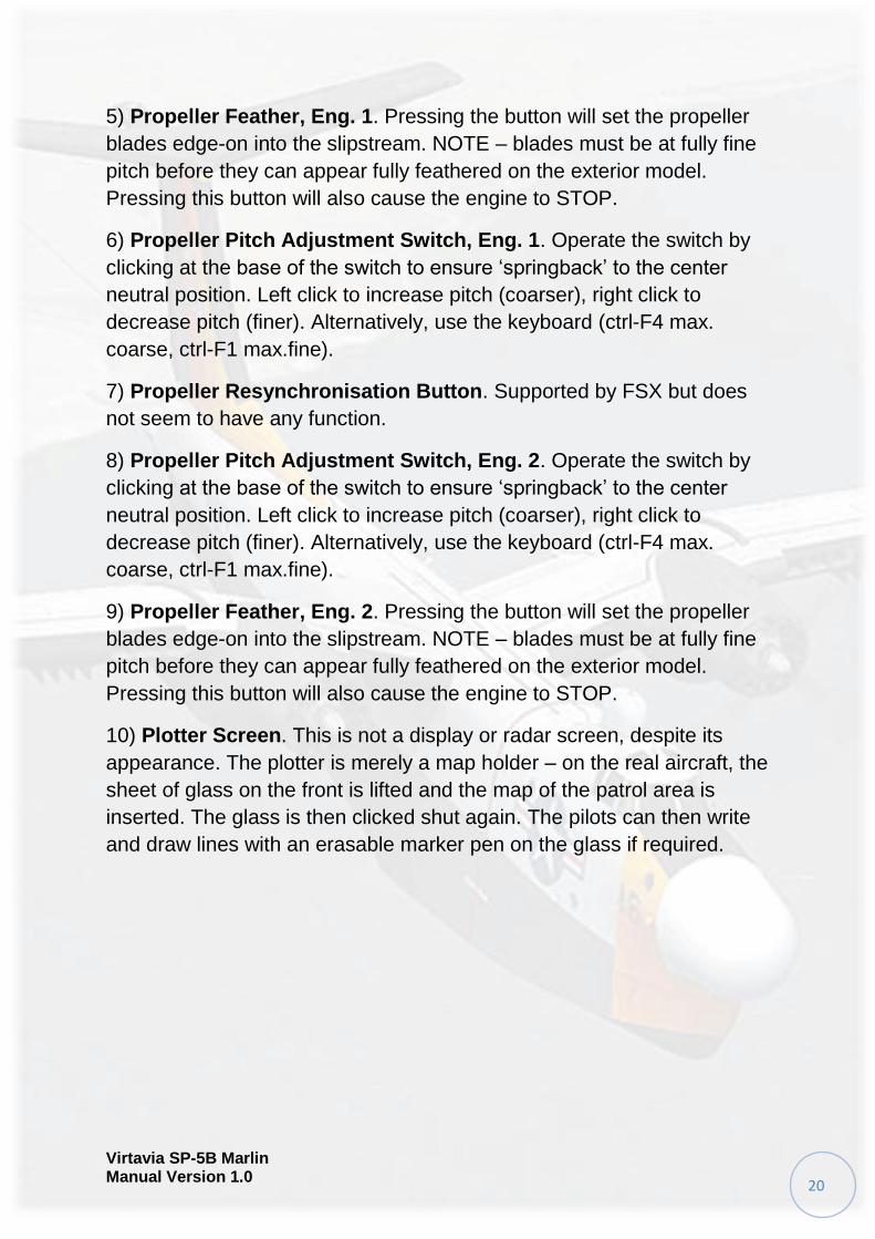
5) Propeller Feather, Eng. 1. Pressing the button will set the propeller
blades edge-on into the slipstream. NOTE – blades must be at fully fine
pitch before they can appear fully feathered on the exterior model.
Pressing this button will also cause the engine to STOP.
6) Propeller Pitch Adjustment Switch, Eng. 1. Operate the switch by
clicking at the base of the switch to ensure ‘springback’ to the center
neutral position. Left click to increase pitch (coarser), right click to
decrease pitch (finer). Alternatively, use the keyboard (ctrl-F4 max.
coarse, ctrl-F1 max.fine).
7) Propeller Resynchronisation Button. Supported by FSX but does
not seem to have any function.
8) Propeller Pitch Adjustment Switch, Eng. 2. Operate the switch by
clicking at the base of the switch to ensure ‘springback’ to the center
neutral position. Left click to increase pitch (coarser), right click to
decrease pitch (finer). Alternatively, use the keyboard (ctrl-F4 max.
coarse, ctrl-F1 max.fine).
9) Propeller Feather, Eng. 2. Pressing the button will set the propeller
blades edge-on into the slipstream. NOTE – blades must be at fully fine
pitch before they can appear fully feathered on the exterior model.
Pressing this button will also cause the engine to STOP.
10) Plotter Screen. This is not a display or radar screen, despite its
appearance. The plotter is merely a map holder – on the real aircraft, the
sheet of glass on the front is lifted and the map of the patrol area is
inserted. The glass is then clicked shut again. The pilots can then write
and draw lines with an erasable marker pen on the glass if required.
Virtavia SP-5B Marlin Manual Version 1.0
21
Pilots Pedestal
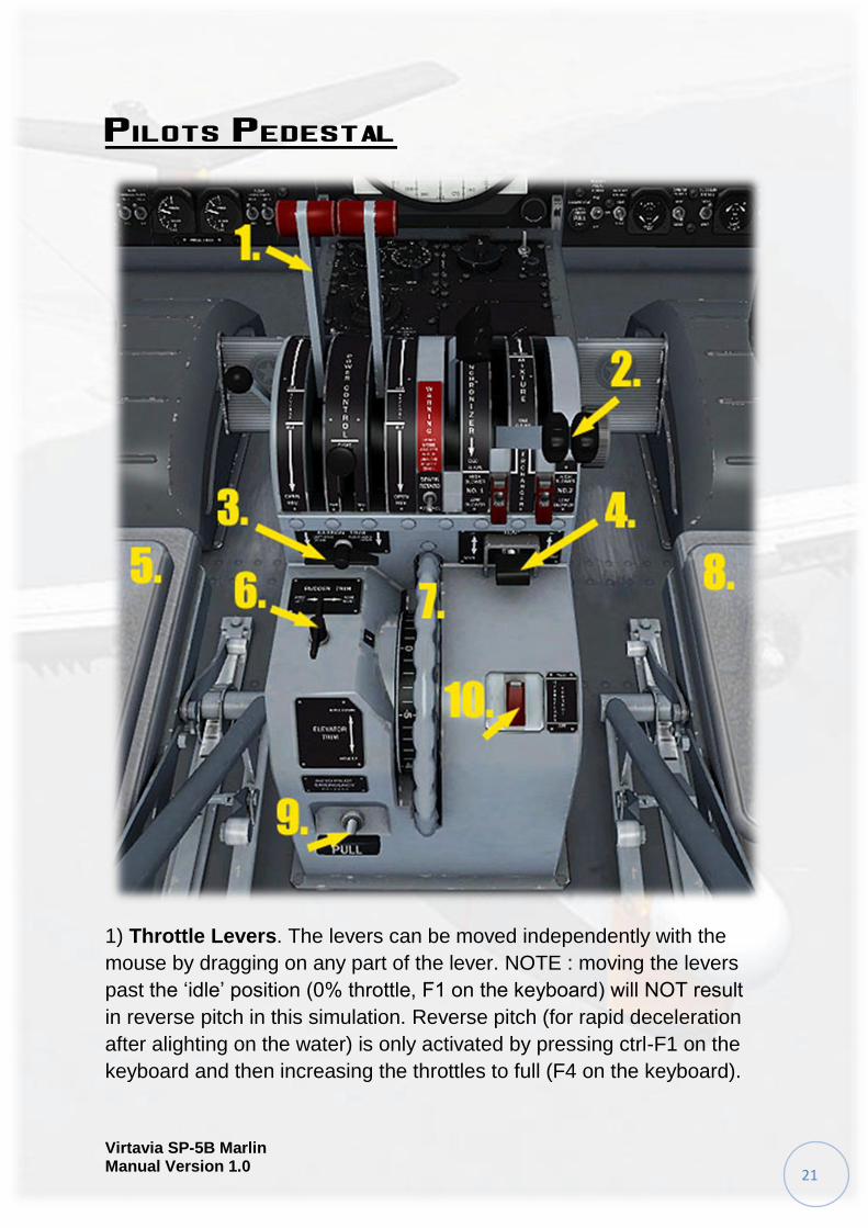
1) Throttle Levers. The levers can be moved independently with the
mouse by dragging on any part of the lever. NOTE : moving the levers
past the ‘idle’ position (0% throttle, F1 on the keyboard) will NOT result
in reverse pitch in this simulation. Reverse pitch (for rapid deceleration
after alighting on the water) is only activated by pressing ctrl-F1 on the
keyboard and then increasing the throttles to full (F4 on the keyboard).
Virtavia SP-5B Marlin Manual Version 1.0
22
2) Mixture Levers. Click and drag the levers to increase or decrease the
fuel/air mixture. Note that the levers must be dragged downwards to
move them forwards, and vice-versa - a peculiarity of FSX.
3) Aileron Trim Knob. Left-clicking with the mouse will apply left wing-
down trim, right clicking applies right wing-down trim. Note the tooltip
displays the exact amount of trim applied in degrees. It is best to click at
the center of the knob as this ensures the knob is able to spring back to
its center neutral position (this does not affect the trim applied).
4) Flaps Switch. Click and drag down to increase flap deflection, drag
up to decrease it. The tooltip displays the actual flap deflection
percentage
5) Armrests. Click with the mouse to raise or lower. Note – it is essential
to raise the outer armrest to expose some important switches on the
side consoles.
6) Rudder Trim Knob. Left-clicking with the mouse will apply nose-left
trim, right clicking applies nose-right trim. Note the tooltip displays the
exact amount of trim applied in degrees. It is best to click at the center of
the knob as this ensures the knob is able to spring back to its center
neutral position (this does not affect the trim applied).
7) Elevator Trim Wheel. Trimming the aircraft pitch can be achieved by
either clicking and dragging the wheel in the desired direction, or by
mousing over it and using the mousewheel.
8) Armrests. Click with the mouse to raise or lower. Note – it is essential
to raise the outer armrest to expose some important switches on the
side consoles.
9) Emergency Autopilot Disengage T-Bar. One click on the handle
and the autopilot will be switched off. Clicking the lever again will return
it to its original position but the AP will stay off until re-engaged on the
AP pop-up panel (click the ‘AP’ sim icon or press shift-2).
10) Hydro Flaps Switch. Click with the mouse to raise the red cover
and throw the switch. The Hydro Flaps can be opened on land to check
their function, but are only of use in the water. Their deployment in the
air is possible but will have no effect on the handling of the aircraft.
Virtavia SP-5B Marlin Manual Version 1.0
23
Pilots Side Console
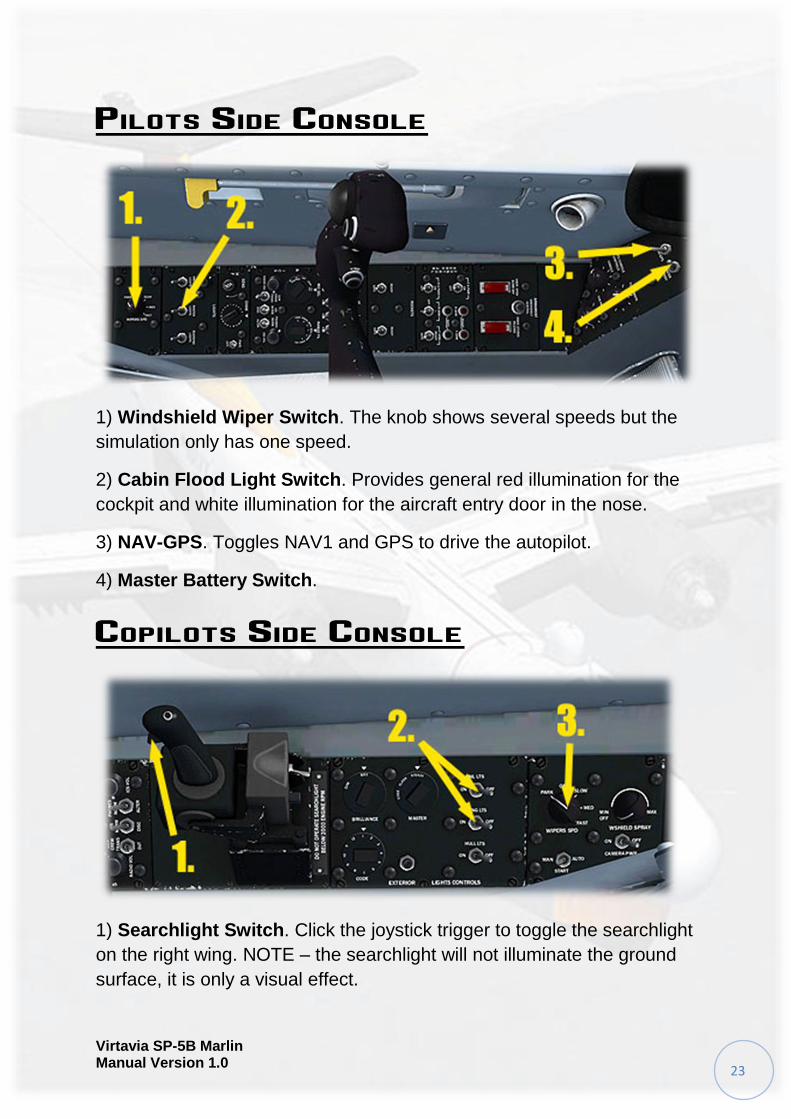
1) Windshield Wiper Switch. The knob shows several speeds but the
simulation only has one speed.
2) Cabin Flood Light Switch. Provides general red illumination for the
cockpit and white illumination for the aircraft entry door in the nose.
3) NAV-GPS. Toggles NAV1 and GPS to drive the autopilot.
4) Master Battery Switch.
Copilots Side Console
1) Searchlight Switch. Click the joystick trigger to toggle the searchlight
on the right wing. NOTE – the searchlight will not illuminate the ground
surface, it is only a visual effect.
Virtavia SP-5B Marlin Manual Version 1.0
24
2) Nav Lights Switch. Both switches operate as one to toggle the
standard red/green/white navigation lights.
3) Windshield Wiper Switch. The knob shows several speeds but the
simulation only has one speed.
Overhead Panel
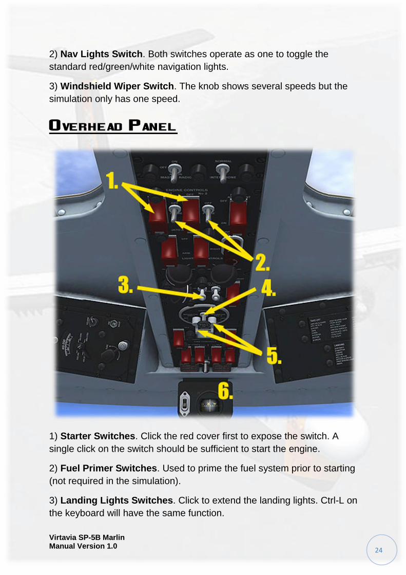
1) Starter Switches. Click the red cover first to expose the switch. A
single click on the switch should be sufficient to start the engine.
2) Fuel Primer Switches. Used to prime the fuel system prior to starting
(not required in the simulation).
3) Landing Lights Switches. Click to extend the landing lights. Ctrl-L on
the keyboard will have the same function.
Virtavia SP-5B Marlin Manual Version 1.0
25
4) Master Ignition Switch. Click to toggle the power to the ignition
system on or off. NOTE – clicking in flight will stop both engines !
5) Magneto Switches. Each has four positions; OFF, L, R and BOTH.
Ensure the ‘BOTH’ position is selected before starting. Setting to ‘OFF’
will stop the engine.
6) Whiskey Compass. A simplified backup compass.
Fuel Panel
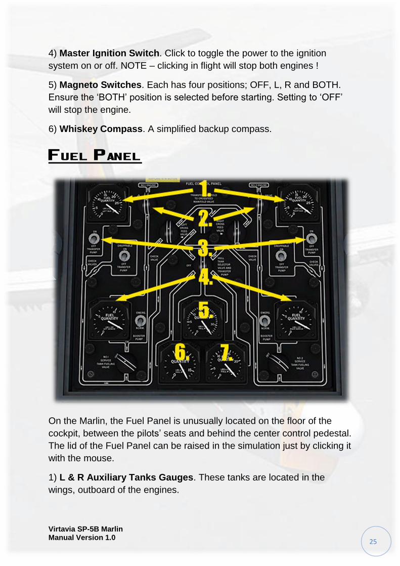
On the Marlin, the Fuel Panel is unusually located on the floor of the
cockpit, between the pilots’ seats and behind the center control pedestal.
The lid of the Fuel Panel can be raised in the simulation just by clicking it
with the mouse.
1) L & R Auxiliary Tanks Gauges. These tanks are located in the
wings, outboard of the engines.
Virtavia SP-5B Marlin Manual Version 1.0
26
2) L & R Main Shutoff Valves. Clicking the knob will shut off all fuel to
the engine. This is the preferred method of stopping the engines.
3) L & R Fuel Transfer Pumps Switches. The switches are supported
by FSX but have no function in this simulation.
4) L & R Service Tanks Gauges. These tanks are located in the wings,
inboard of the engines.
5) Hull Tank No.1 Gauge. This tank is located in the forward fuselage.
6) Hull Tank No.2 Gauge. This tank is located in the center fuselage.
7) Hull Tank No.3 Gauge. This tank is located in the aft fuselage.
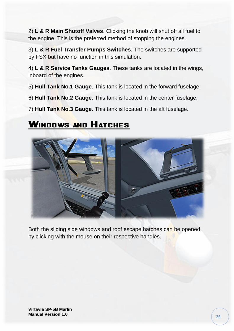
Windows and Hatches
Both the sliding side windows and roof escape hatches can be opened
by clicking with the mouse on their respective handles.
Virtavia SP-5B Marlin Manual Version 1.0
27
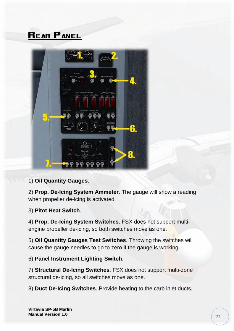
Rear Panel
1) Oil Quantity Gauges.
2) Prop. De-Icing System Ammeter. The gauge will show a reading
when propeller de-icing is activated.
3) Pitot Heat Switch.
4) Prop. De-Icing System Switches. FSX does not support multi-
engine propeller de-icing, so both switches move as one.
5) Oil Quantity Gauges Test Switches. Throwing the switches will
cause the gauge needles to go to zero if the gauge is working.
6) Panel Instrument Lighting Switch.
7) Structural De-Icing Switches. FSX does not support multi-zone
structural de-icing, so all switches move as one.
8) Duct De-Icing Switches. Provide heating to the carb inlet ducts.
Virtavia SP-5B Marlin Manual Version 1.0
28
REFERENCE INFORMATION
Virtavia SP-5B Marlin Procedures
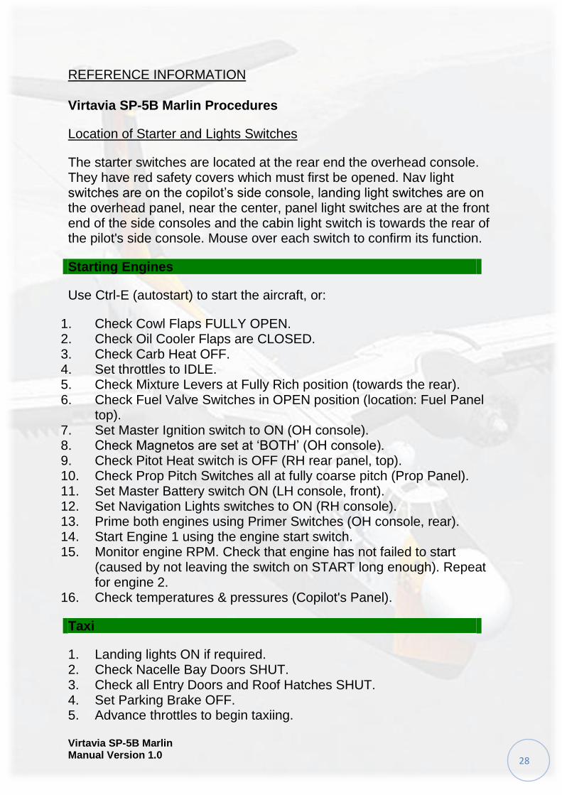
Location of Starter and Lights Switches
The starter switches are located at the rear end the overhead console. They have red safety covers which must first be opened. Nav light switches are on the copilot’s side console, landing light switches are on the overhead panel, near the center, panel light switches are at the front end of the side consoles and the cabin light switch is towards the rear of the pilot's side console. Mouse over each switch to confirm its function.
Starting Engines
Use Ctrl-E (autostart) to start the aircraft, or:
1. Check Cowl Flaps FULLY OPEN. 2. Check Oil Cooler Flaps are CLOSED. 3. Check Carb Heat OFF. 4. Set throttles to IDLE. 5. Check Mixture Levers at Fully Rich position (towards the rear). 6. Check Fuel Valve Switches in OPEN position (location: Fuel Panel
top). 7. Set Master Ignition switch to ON (OH console). 8. Check Magnetos are set at ‘BOTH’ (OH console). 9. Check Pitot Heat switch is OFF (RH rear panel, top). 10. Check Prop Pitch Switches all at fully coarse pitch (Prop Panel). 11. Set Master Battery switch ON (LH console, front). 12. Set Navigation Lights switches to ON (RH console). 13. Prime both engines using Primer Switches (OH console, rear). 14. Start Engine 1 using the engine start switch. 15. Monitor engine RPM. Check that engine has not failed to start
(caused by not leaving the switch on START long enough). Repeat for engine 2.
16. Check temperatures & pressures (Copilot's Panel).
Taxi
1. Landing lights ON if required. 2. Check Nacelle Bay Doors SHUT. 3. Check all Entry Doors and Roof Hatches SHUT. 4. Set Parking Brake OFF. 5. Advance throttles to begin taxiing.
Virtavia SP-5B Marlin Manual Version 1.0
29
Water Entry
1. Taxi into water. Do not attempt to take off from a runway ! 2. Turn Hydro Flaps ON (Covered switch, center console). 3. Toggle Beaching Gear OFF (red warning lamp will go off on panel). 4. Taxi to desired takeoff zone. 5. Turn aircraft into wind.
Takeoff
1. This section assumes maximum fuel load in all tanks. 2. Turn Hydro Flaps OFF. 3. Check Autopilot OFF. 4. Set Pitot Heat ON. 5. Set flaps to takeoff (30 degrees on gauge). 6. Set Cowl Flaps 3/4 OPEN. 7. Set Prop Pitch COARSE (default FSX setting, ctrl-F4 if needed). 8. Apply power smoothly to full throttle. 9. Take off occurs at approx. 100 KTS IAS.
After Takeoff
1. At 110 KTS start raising FLAPS. 2. At 140 KTS check FLAPS UP. 3. Set Cowl Flaps CLOSED. 4. Set Oil Cooler Flaps OPEN. 5. Allow the aircraft to accelerate to the normal climb speed of 134 KTS
(74,601 lbs, ASL).
Cruising
1. Level off at desired cruise altitude. 2. Adjust speed to max. cruise speed 138 KTS. 3. Use autopilot to set cruise parameters.
Descent
1. Begin descent 40 miles from the landing zone. 2. Check Pitot Heat ON. 3. Set Cowl Flaps 1/2 OPEN. 4. Check Searchlight is OFF. 5. Set descent rate and speed as desired using the autopilot.
Virtavia SP-5B Marlin Manual Version 1.0
30
Final Approach
1. Landing lights ON, if required. 2. Set Autopilot OFF. 3. Set Altimeter Baro Pressure to match landing zone pressure. 4. Enter downwind leg at 130 KTS. 5. Set Flaps to 10 Degrees.
Landing
1. Check Autopilot is OFF. 2. Visual check no water craft or other obstructions in landing zone. 3. Maintain 100 - 108 KTS. 4. Set FLAPS FULLY DOWN 5. Visual check sea state is safe for landing. 6. Touchdown speed is 88 KTS for 74,601 lbs (normal ASW mission
TOW). 7. Apply full reverse thrust (ctrl-F1 and full throttle) to slow aircraft. 8. Cancel Reverse Thrust at 30 KTS (reset coarse pitch with ctrl-F4). 9. Set Hydro Flaps ON.
Exiting Water
1. Set FLAPS UP. 2. Set Cowl Flaps FULLY OPEN. 3. Set Oil Cooler Flaps are CLOSED. 4. Taxi to ramp or beaching area. 5. Set Beaching Gear ON (red lamp on panel will illuminate). 6. Set Hydro Flaps OFF. 7. Taxi up ramp or beach at approx. 25 KTS. 8. Taxi to parking area. 9. Set Parking Brake ON.
Shutdown
1. Set Landing Lights to OFF. 2. Stop engines using Fuel Valve Switches. 3. Set Magnetos and Master Ignition Switch to OFF. 4. Set Pitot Heat and Navigation Lights to OFF. 5. Set all cockpit and cabin lighting to OFF. 6. Set Master Battery Switch to OFF.
Virtavia SP-5B Marlin Manual Version 1.0
31
SP-5B Marlin Specifications and Speed References
Specifications
Crew: 11
Engines: 2 x Wright R3350-32WA Radials
Horsepower: 3,450 s.h.p. per engine
Wingspan: 117' 2"
Length: 100' 2"
Tail Height: 32' 9”
Empty Weight : 50,485 pounds
Loaded Weight : 72,600 pounds
MTOW : 85,000 pounds
Armament: Unguided bombs, mines, rockets or torpedoes on
underwing mounts or carried in nacelle bomb bays. Option for 1
Mk.90 'Betty' nuclear depth charge.
Flight Reference Data
Maximum speed: 218 kts
Max. cont. cruising speed: 130 kts
Max. Range: 1,783 miles
Service Ceiling: 24,000 feet
Max. Fuel Load: 3,993 lbs
Max. climb rate: 1,200 feet per minute at Sea Level
Stall Speeds @ 56,000 lbs: Clean - 87 kts, Landing - 74.5 kts
Stall Speeds @ 74,000 lbs: Clean - 100.4 kts, Landing - 86.2 kts
Stall Speeds @ 78,000 lbs: Clean - 103 kts, Landing - 88 kts


![New t New CUBEs with Heavy Attitude t - American Musical Supply · 2013. 11. 26. · METAL ZONE, EXTREME), GAIN Knob, VOLUME Knob, [EQUALIZER] BASS Knob, MIDDLE Knob, TREBLE Knob](https://img.pdfslide.us/doc/110x75/6067859789f730682b1d8a47/new-t-new-cubes-with-heavy-attitude-t-american-musical-supply-2013-11-26.jpg)


![t New CUBEs with Heavy Attitude t€¦ · METAL ZONE, EXTREME), GAIN Knob, VOLUME Knob, [EQUALIZER] BASS Knob, MIDDLE Knob, TREBLE Knob Indicators CLEAN Channel, LEAD Channel Connectors](https://img.pdfslide.us/doc/110x75/6067859789f730682b1d8a48/t-new-cubes-with-heavy-attitude-t-metal-zone-extreme-gain-knob-volume-knob.jpg)