Embed Size (px)
Citation preview

10
Living up to Life
User ManualLeica TCS SP8 SMDfor FCS, FLIM and FLCS

Published by:
Leica Microsystems CMS GmbHAm Friedensplatz 3D-68165 Mannheim (Germany)
http://www.leica-microsystems.comhttp://www.confocal-microscopy.com
Responsible for contents: Leica Microsystems CMS GmbH
Copyright © Leica Microsystems CMS GmbH.All rights reserved.
This manual was created in cooperation with PicoQuant GmbH:
PicoQuant GmbHRudower Chaussee 29 12489 Berlin (Germany)
http://www.picoquant.com

3
Copyright
Copyright
All rights to this document are held by Leica Microsystems CMS GmbH. Adaptation, translation and reproduction of text or illustrations (in whole or in part) by print, photocopy, microfilm or other method (including electronic systems) is not allowed without express written permission from Leica Microsystems CMS GmbH.
Programs such as LAS and LAS AF are protected by copyright laws. All rights reserved. Reproduction, adaptation or translation of these programs is prohibited without prior written permission from Leica Microsystems CMS GmbH.
This User Manual specifies names of products or services that are trademarks or registered trademarks of the respective trademark owners. Rather than including a trademark (TM or ®) symbol at every occurrence of a trademarked name, we state that we are using the names only in an editorial fashion, and to the benefit of the trademark owner, with no intention of infringement.
Made in Germany.
© Copyright Leica Microsystems CMS GmbH.
All rights reserved.

4
Copyright

5
Contents
Contents
Copyright. . . . . . . . . . . . . . . . . . . . . . . . . . . . . . . . . . . . . . . . . . . . . . . . . . . . . . . . . . . . . . . . . . . . .3
Contents . . . . . . . . . . . . . . . . . . . . . . . . . . . . . . . . . . . . . . . . . . . . . . . . . . . . . . . . . . . . . . . . . . . . .5
1 About this User Manual . . . . . . . . . . . . . . . . . . . . . . . . . . . . . . . . . . . . . . . . . . . . . . . . . . . . . .15
1.1 Additional Documentation . . . . . . . . . . . . . . . . . . . . . . . . . . . . . . . . . . . . . . . . . . . . . . .16
2 Intended Use . . . . . . . . . . . . . . . . . . . . . . . . . . . . . . . . . . . . . . . . . . . . . . . . . . . . . . . . . . . . . . . .17
3 Liability and Warranty . . . . . . . . . . . . . . . . . . . . . . . . . . . . . . . . . . . . . . . . . . . . . . . . . . . . . . . .19
3.1 Important Information for Operators and Users . . . . . . . . . . . . . . . . . . . . . . . . . . . . .19
4 Meaning of the warning messages in the manual . . . . . . . . . . . . . . . . . . . . . . . . . . . . . . . .21
5 General Safety Notes . . . . . . . . . . . . . . . . . . . . . . . . . . . . . . . . . . . . . . . . . . . . . . . . . . . . . . . . .23
5.1 Commissioning and Use . . . . . . . . . . . . . . . . . . . . . . . . . . . . . . . . . . . . . . . . . . . . . . . . .23
5.2 Modifications to the System . . . . . . . . . . . . . . . . . . . . . . . . . . . . . . . . . . . . . . . . . . . . .24
5.3 Safety Devices and Safety Labels. . . . . . . . . . . . . . . . . . . . . . . . . . . . . . . . . . . . . . . . .24
5.4 Laser Safety . . . . . . . . . . . . . . . . . . . . . . . . . . . . . . . . . . . . . . . . . . . . . . . . . . . . . . . . . . .24
5.5 Electrical Safety . . . . . . . . . . . . . . . . . . . . . . . . . . . . . . . . . . . . . . . . . . . . . . . . . . . . . . . .26
5.6 Contact with Liquids . . . . . . . . . . . . . . . . . . . . . . . . . . . . . . . . . . . . . . . . . . . . . . . . . . . .26
5.7 Malfunction of the System . . . . . . . . . . . . . . . . . . . . . . . . . . . . . . . . . . . . . . . . . . . . . . .26
6 Additional Notes on Handling the System . . . . . . . . . . . . . . . . . . . . . . . . . . . . . . . . . . . . . . .29
6.1 Location . . . . . . . . . . . . . . . . . . . . . . . . . . . . . . . . . . . . . . . . . . . . . . . . . . . . . . . . . . . . . . .29
6.2 Using the Software . . . . . . . . . . . . . . . . . . . . . . . . . . . . . . . . . . . . . . . . . . . . . . . . . . . . .29
6.3 Protecting the System. . . . . . . . . . . . . . . . . . . . . . . . . . . . . . . . . . . . . . . . . . . . . . . . . . .30
6.3.1 Objectives . . . . . . . . . . . . . . . . . . . . . . . . . . . . . . . . . . . . . . . . . . . . . . . . . . . . . . . . . .31
7 System Overview and Properties. . . . . . . . . . . . . . . . . . . . . . . . . . . . . . . . . . . . . . . . . . . . . . .33
7.1 TCS SP8 SMD System Variants . . . . . . . . . . . . . . . . . . . . . . . . . . . . . . . . . . . . . . . . . . .33
7.1.1 TCS SP8 SMD System Components . . . . . . . . . . . . . . . . . . . . . . . . . . . . . . . . . . . .33
7.1.2 TCS SP8 SMD with Upright Microscope . . . . . . . . . . . . . . . . . . . . . . . . . . . . . . . .34
7.1.3 TCS SP8 SMD with Inverted Microscope . . . . . . . . . . . . . . . . . . . . . . . . . . . . . . .34
7.2 TCS SP8 SMD System Variants with White Light Laser . . . . . . . . . . . . . . . . . . . . . .35
7.2.1 TCS SP8 SMD System Components with White Light Laser. . . . . . . . . . . . . . . .35
7.2.2 TCS SP8 SMD with White Light Laser and Upright Microscope . . . . . . . . . . . .36
7.2.3 TCS SP8 SMD with White Light Laser and Inverted Microscope . . . . . . . . . . .37
7.3 TCS SP8 SMD System Variants with MP Configuration . . . . . . . . . . . . . . . . . . . . . .38
7.4 Controls on the Supply Unit . . . . . . . . . . . . . . . . . . . . . . . . . . . . . . . . . . . . . . . . . . . . . .40

6
Contents
7.4.1 Main Switch Board on the Flexible Supply Unit . . . . . . . . . . . . . . . . . . . . . . . . . .40
7.4.2 Control Panel Field on the Compact Supply Unit (Only for FLIM). . . . . . . . . . . .40
7.5 Technical Data . . . . . . . . . . . . . . . . . . . . . . . . . . . . . . . . . . . . . . . . . . . . . . . . . . . . . . . . .41
7.5.1 Dimensions . . . . . . . . . . . . . . . . . . . . . . . . . . . . . . . . . . . . . . . . . . . . . . . . . . . . . . . . .41
7.5.2 Weight . . . . . . . . . . . . . . . . . . . . . . . . . . . . . . . . . . . . . . . . . . . . . . . . . . . . . . . . . . . . .41
7.5.3 Electrical Specifications . . . . . . . . . . . . . . . . . . . . . . . . . . . . . . . . . . . . . . . . . . . . . .42
7.6 "Electromagnetic Compatibility". . . . . . . . . . . . . . . . . . . . . . . . . . . . . . . . . . . . . . . . . . .42
7.7 Serial Number. . . . . . . . . . . . . . . . . . . . . . . . . . . . . . . . . . . . . . . . . . . . . . . . . . . . . . . . . .43
8 Ambient Conditions. . . . . . . . . . . . . . . . . . . . . . . . . . . . . . . . . . . . . . . . . . . . . . . . . . . . . . . . . . .45
8.1 General Requirements Regarding Ambient Conditions. . . . . . . . . . . . . . . . . . . . . . .45
8.2 Vibrations. . . . . . . . . . . . . . . . . . . . . . . . . . . . . . . . . . . . . . . . . . . . . . . . . . . . . . . . . . . . . .45
8.3 Room Dimensions . . . . . . . . . . . . . . . . . . . . . . . . . . . . . . . . . . . . . . . . . . . . . . . . . . . . . .46
8.4 Electrical Connection Requirements . . . . . . . . . . . . . . . . . . . . . . . . . . . . . . . . . . . . . .47
8.4.1 System with Flexible Supply Unit. . . . . . . . . . . . . . . . . . . . . . . . . . . . . . . . . . . . . . .47
8.4.2 System with Compact Supply Unit (Only with FLIM) . . . . . . . . . . . . . . . . . . . . . .48
8.4.3 External Lasers . . . . . . . . . . . . . . . . . . . . . . . . . . . . . . . . . . . . . . . . . . . . . . . . . . . . . .48
8.5 Load capacity of the multiple socket outlet on the flexible supply unit . . . . . . . . .49
8.6 Waste Heat and Cooling . . . . . . . . . . . . . . . . . . . . . . . . . . . . . . . . . . . . . . . . . . . . . . . . .49
8.6.1 System with Flexible Supply Unit. . . . . . . . . . . . . . . . . . . . . . . . . . . . . . . . . . . . . . .50
8.6.2 System with Compact Supply Unit (Only with FLIM) . . . . . . . . . . . . . . . . . . . . . .50
8.6.3 External Lasers . . . . . . . . . . . . . . . . . . . . . . . . . . . . . . . . . . . . . . . . . . . . . . . . . . . . . .50
9 SMD Components . . . . . . . . . . . . . . . . . . . . . . . . . . . . . . . . . . . . . . . . . . . . . . . . . . . . . . . . . . . .51
9.1 Hardware Components and Software Licenses. . . . . . . . . . . . . . . . . . . . . . . . . . . . .51
9.1.1 FCS/FCCS Application Area . . . . . . . . . . . . . . . . . . . . . . . . . . . . . . . . . . . . . . . . . . .51
9.1.1.1 Special SMD Hardware. . . . . . . . . . . . . . . . . . . . . . . . . . . . . . . . . . . . . . . . . . . .51
9.1.1.2 Software License . . . . . . . . . . . . . . . . . . . . . . . . . . . . . . . . . . . . . . . . . . . . . . . . .51
9.1.2 FLIM Application Area. . . . . . . . . . . . . . . . . . . . . . . . . . . . . . . . . . . . . . . . . . . . . . . .52
9.1.2.1 Special SMD Hardware. . . . . . . . . . . . . . . . . . . . . . . . . . . . . . . . . . . . . . . . . . . .52
9.1.2.2 Software License . . . . . . . . . . . . . . . . . . . . . . . . . . . . . . . . . . . . . . . . . . . . . . . . .52
9.1.3 Application area FCS/FCCS, FLIM, FLCS, gated FCS . . . . . . . . . . . . . . . . . . . . . .53
9.1.3.1 Special SMD Hardware. . . . . . . . . . . . . . . . . . . . . . . . . . . . . . . . . . . . . . . . . . . .53
9.1.3.2 Software License . . . . . . . . . . . . . . . . . . . . . . . . . . . . . . . . . . . . . . . . . . . . . . . . .53
9.2 Beam Path . . . . . . . . . . . . . . . . . . . . . . . . . . . . . . . . . . . . . . . . . . . . . . . . . . . . . . . . . . . . .53
9.3 Detection Units from PicoQuant . . . . . . . . . . . . . . . . . . . . . . . . . . . . . . . . . . . . . . . . . .54
9.4 Leica APD Detector Unit . . . . . . . . . . . . . . . . . . . . . . . . . . . . . . . . . . . . . . . . . . . . . . . . .55
9.4.1 General Precautionary Measures for Using APD Detector Units . . . . . . . . . . .56
9.4.2 Changing the Fuse . . . . . . . . . . . . . . . . . . . . . . . . . . . . . . . . . . . . . . . . . . . . . . . . . . .56
9.4.3 Safety Shutoff . . . . . . . . . . . . . . . . . . . . . . . . . . . . . . . . . . . . . . . . . . . . . . . . . . . . . . .56

7
Contents
9.5 Trigger Unit . . . . . . . . . . . . . . . . . . . . . . . . . . . . . . . . . . . . . . . . . . . . . . . . . . . . . . . . . . . .56
9.6 Laser Coupling Unit (LCU) . . . . . . . . . . . . . . . . . . . . . . . . . . . . . . . . . . . . . . . . . . . . . . . .57
9.6.1 Attenuation Unit . . . . . . . . . . . . . . . . . . . . . . . . . . . . . . . . . . . . . . . . . . . . . . . . . . . . .58
9.6.2 Other PicoQuant Components . . . . . . . . . . . . . . . . . . . . . . . . . . . . . . . . . . . . . . . . .59
10 Laser . . . . . . . . . . . . . . . . . . . . . . . . . . . . . . . . . . . . . . . . . . . . . . . . . . . . . . . . . . . . . . . . . . . . . . .61
10.1 Laser Classes . . . . . . . . . . . . . . . . . . . . . . . . . . . . . . . . . . . . . . . . . . . . . . . . . . . . . . . . . .61
10.2 Overview of Usable Lasers for Image Acquisition . . . . . . . . . . . . . . . . . . . . . . . . . . .61
10.2.1 VIS/UV Lasers for TCS SP8. . . . . . . . . . . . . . . . . . . . . . . . . . . . . . . . . . . . . . . . . . . .61
10.2.2 VIS/UV Lasers for TCS SP8 X . . . . . . . . . . . . . . . . . . . . . . . . . . . . . . . . . . . . . . . . . .62
10.2.3 IR lasers for TCS SP8 MP . . . . . . . . . . . . . . . . . . . . . . . . . . . . . . . . . . . . . . . . . . . . .62
10.2.3.1 Picosecond laser . . . . . . . . . . . . . . . . . . . . . . . . . . . . . . . . . . . . . . . . . . . . . . . . .62
10.2.3.2 Femtosecond laser. . . . . . . . . . . . . . . . . . . . . . . . . . . . . . . . . . . . . . . . . . . . . . . .63
10.3 Overview of Usable Lasers for FCS. . . . . . . . . . . . . . . . . . . . . . . . . . . . . . . . . . . . . . . .63
10.3.1 VIS/UV Lasers for TCS SP8 SMD. . . . . . . . . . . . . . . . . . . . . . . . . . . . . . . . . . . . . . .63
10.4 Overview of usable lasers for FLIM . . . . . . . . . . . . . . . . . . . . . . . . . . . . . . . . . . . . . . .64
10.4.1 VIS/UV Lasers for TCS SP8 SMD. . . . . . . . . . . . . . . . . . . . . . . . . . . . . . . . . . . . . . .64
10.4.2 Infrared Lasers for TCS SP8 SMD with MP Configuration . . . . . . . . . . . . . . . . .64
10.4.2.1 Picosecond laser . . . . . . . . . . . . . . . . . . . . . . . . . . . . . . . . . . . . . . . . . . . . . . . . .64
10.4.2.2 Femtosecond laser. . . . . . . . . . . . . . . . . . . . . . . . . . . . . . . . . . . . . . . . . . . . . . . .64
10.5 Overview of Usable Lasers for FLCS. . . . . . . . . . . . . . . . . . . . . . . . . . . . . . . . . . . . . . .66
10.5.1 VIS/UV Lasers for TCS SP8 SMD. . . . . . . . . . . . . . . . . . . . . . . . . . . . . . . . . . . . . . .66
11 Safety Features . . . . . . . . . . . . . . . . . . . . . . . . . . . . . . . . . . . . . . . . . . . . . . . . . . . . . . . . . . . . . .67
11.1 Main Circuit Breaker for Disconnecting the Power Supply . . . . . . . . . . . . . . . . . . .67
11.1.1 Compact Supply Unit . . . . . . . . . . . . . . . . . . . . . . . . . . . . . . . . . . . . . . . . . . . . . . . . .67
11.1.2 Flexible Supply Unit . . . . . . . . . . . . . . . . . . . . . . . . . . . . . . . . . . . . . . . . . . . . . . . . . .67
11.1.3 Other Components . . . . . . . . . . . . . . . . . . . . . . . . . . . . . . . . . . . . . . . . . . . . . . . . . . .68
11.2 Key Switch . . . . . . . . . . . . . . . . . . . . . . . . . . . . . . . . . . . . . . . . . . . . . . . . . . . . . . . . . . . .68
11.2.1 Master Key Switch on the Compact Supply Unit . . . . . . . . . . . . . . . . . . . . . . . . .68
11.2.2 Master Key Switch on the Flexible Supply Unit . . . . . . . . . . . . . . . . . . . . . . . . . .68
11.2.3 Key Switch for the White Light Laser . . . . . . . . . . . . . . . . . . . . . . . . . . . . . . . . . . .69
11.2.4 Key Switch for UV Lasers . . . . . . . . . . . . . . . . . . . . . . . . . . . . . . . . . . . . . . . . . . . . .69
11.2.5 Key Switches for Other External Lasers. . . . . . . . . . . . . . . . . . . . . . . . . . . . . . . . .70
11.3 Emission Warning Indicators . . . . . . . . . . . . . . . . . . . . . . . . . . . . . . . . . . . . . . . . . . . . .70
11.3.1 Emission Warning Indicator on the Supply Unit . . . . . . . . . . . . . . . . . . . . . . . . . .70
11.3.2 Emission Warning Indicator on the White Light Laser . . . . . . . . . . . . . . . . . . . .71
11.3.3 Emission Warning Indicator on UV Lasers . . . . . . . . . . . . . . . . . . . . . . . . . . . . . .71
11.3.4 Emission Warning Indicator on Other External Lasers . . . . . . . . . . . . . . . . . . . .72
11.3.5 Malfunction of Emission Warning Indicator . . . . . . . . . . . . . . . . . . . . . . . . . . . . .72

8
Contents
11.4 Interlock Connectors . . . . . . . . . . . . . . . . . . . . . . . . . . . . . . . . . . . . . . . . . . . . . . . . . . . .72
11.4.1 Interlock Connector on the Supply Unit . . . . . . . . . . . . . . . . . . . . . . . . . . . . . . . . .72
11.4.2 Interlock Connector on the White Light Laser . . . . . . . . . . . . . . . . . . . . . . . . . . .74
11.4.3 Interlock Connector on Other External Lasers . . . . . . . . . . . . . . . . . . . . . . . . . . .74
11.4.4 Interlock Connector on the Scan Head . . . . . . . . . . . . . . . . . . . . . . . . . . . . . . . . .75
11.5 Safety Switches on the Microscope . . . . . . . . . . . . . . . . . . . . . . . . . . . . . . . . . . . . . .76
11.6 Warning Messages . . . . . . . . . . . . . . . . . . . . . . . . . . . . . . . . . . . . . . . . . . . . . . . . . . . . .76
11.7 Special Laser Safety Equipment . . . . . . . . . . . . . . . . . . . . . . . . . . . . . . . . . . . . . . . . . .78
11.7.1 Laser Protection Tube and Laser Protection Shield . . . . . . . . . . . . . . . . . . . . . .78
11.7.2 Safety Beam Guide on the MP System. . . . . . . . . . . . . . . . . . . . . . . . . . . . . . . . . .79
12 Safety Labels on the System . . . . . . . . . . . . . . . . . . . . . . . . . . . . . . . . . . . . . . . . . . . . . . . . . . .81
12.1 Compact Supply Unit (Only for FLIM) . . . . . . . . . . . . . . . . . . . . . . . . . . . . . . . . . . . . . .81
12.2 Flexible Supply Unit . . . . . . . . . . . . . . . . . . . . . . . . . . . . . . . . . . . . . . . . . . . . . . . . . . . . .82
12.3 Inverted Microscope. . . . . . . . . . . . . . . . . . . . . . . . . . . . . . . . . . . . . . . . . . . . . . . . . . . .83
12.4 Upright Microscope. . . . . . . . . . . . . . . . . . . . . . . . . . . . . . . . . . . . . . . . . . . . . . . . . . . . .84
12.5 Mirror Housing . . . . . . . . . . . . . . . . . . . . . . . . . . . . . . . . . . . . . . . . . . . . . . . . . . . . . . . . .85
12.6 Cover for Replacement Flange . . . . . . . . . . . . . . . . . . . . . . . . . . . . . . . . . . . . . . . . . . .86
12.7 Transmitted Light Detector (TLD)/Reflected Light Detector (RLD) . . . . . . . . . . . . .87
12.8 Scan Head . . . . . . . . . . . . . . . . . . . . . . . . . . . . . . . . . . . . . . . . . . . . . . . . . . . . . . . . . . . . .87
12.9 White Light Laser . . . . . . . . . . . . . . . . . . . . . . . . . . . . . . . . . . . . . . . . . . . . . . . . . . . . . . .89
12.10 External UV Laser. . . . . . . . . . . . . . . . . . . . . . . . . . . . . . . . . . . . . . . . . . . . . . . . . . . . . . .89
12.11 MP Beam Coupling Unit . . . . . . . . . . . . . . . . . . . . . . . . . . . . . . . . . . . . . . . . . . . . . . . . .90
12.12 Other External Lasers . . . . . . . . . . . . . . . . . . . . . . . . . . . . . . . . . . . . . . . . . . . . . . . . . . .90
13 Switching On the System. . . . . . . . . . . . . . . . . . . . . . . . . . . . . . . . . . . . . . . . . . . . . . . . . . . . . .91
13.1 Confocal System with Flexible Supply Unit . . . . . . . . . . . . . . . . . . . . . . . . . . . . . . . . .91
13.2 Confocal System with Compact Supply Unit (Only with FLIM). . . . . . . . . . . . . . . . .96
13.3 HyD Reflected Light Detectors (HyD RLDs) . . . . . . . . . . . . . . . . . . . . . . . . . . . . . . . . .99
13.4 Starting the SMD Hardware and Software . . . . . . . . . . . . . . . . . . . . . . . . . . . . . . . .100
14 LAS AF . . . . . . . . . . . . . . . . . . . . . . . . . . . . . . . . . . . . . . . . . . . . . . . . . . . . . . . . . . . . . . . . . . . . .103
14.1 Starting LAS AF . . . . . . . . . . . . . . . . . . . . . . . . . . . . . . . . . . . . . . . . . . . . . . . . . . . . . . .103
14.2 Structure of the Graphical User Interface. . . . . . . . . . . . . . . . . . . . . . . . . . . . . . . . .104
14.3 Design of the FLIM Wizard in LAS AF . . . . . . . . . . . . . . . . . . . . . . . . . . . . . . . . . . . . .107
14.4 Design of the FCS Wizard in LAS AF. . . . . . . . . . . . . . . . . . . . . . . . . . . . . . . . . . . . . .110
14.5 LAS AF Online Help . . . . . . . . . . . . . . . . . . . . . . . . . . . . . . . . . . . . . . . . . . . . . . . . . . . .113
14.5.1 Structure of Online Help . . . . . . . . . . . . . . . . . . . . . . . . . . . . . . . . . . . . . . . . . . . . .113
14.5.2 Accessing Online Help . . . . . . . . . . . . . . . . . . . . . . . . . . . . . . . . . . . . . . . . . . . . . .113
9
Contents
14.5.3 Selecting the Language for Online Help. . . . . . . . . . . . . . . . . . . . . . . . . . . . . . . .113
14.5.4 Using Online Help. . . . . . . . . . . . . . . . . . . . . . . . . . . . . . . . . . . . . . . . . . . . . . . . . . .114
14.5.5 Full-text Search with Logically Connected Search Terms . . . . . . . . . . . . . . . .115
15 Selecting the Laser . . . . . . . . . . . . . . . . . . . . . . . . . . . . . . . . . . . . . . . . . . . . . . . . . . . . . . . . . .117
15.1 Activate laser as the excitation source in the configuration menu . . . . . . . . . . .117
15.1.1 Using Continuous Wave VIS Lasers . . . . . . . . . . . . . . . . . . . . . . . . . . . . . . . . . . .118
15.1.2 Using MP lasers . . . . . . . . . . . . . . . . . . . . . . . . . . . . . . . . . . . . . . . . . . . . . . . . . . . .119
15.1.3 Using Pulsed VIS Lasers . . . . . . . . . . . . . . . . . . . . . . . . . . . . . . . . . . . . . . . . . . . . .121
15.1.4 Using Pulsed UV Lasers . . . . . . . . . . . . . . . . . . . . . . . . . . . . . . . . . . . . . . . . . . . . .124
15.1.5 Using a Pulsed White Light Laser . . . . . . . . . . . . . . . . . . . . . . . . . . . . . . . . . . . . .124
16 FLIM Data Acquisition . . . . . . . . . . . . . . . . . . . . . . . . . . . . . . . . . . . . . . . . . . . . . . . . . . . . . . .127
16.1 Setup Imaging Step – Image Acquisition. . . . . . . . . . . . . . . . . . . . . . . . . . . . . . . . . .127
16.1.1 Selecting Detectors for the Image Acquisition. . . . . . . . . . . . . . . . . . . . . . . . . .127
16.1.1.1 Internal Photomultipliers (Including SP FLIM PMT) . . . . . . . . . . . . . . . . . . .127
16.1.1.2 External APDs . . . . . . . . . . . . . . . . . . . . . . . . . . . . . . . . . . . . . . . . . . . . . . . . . . .129
16.1.1.3 External FLIM Photomultiplier . . . . . . . . . . . . . . . . . . . . . . . . . . . . . . . . . . . . .130
16.1.2 Selecting Laser Lines as an Excitation Source for Image Acquisition . . . . . .130
16.1.2.1 Using Continuous Wave Lasers . . . . . . . . . . . . . . . . . . . . . . . . . . . . . . . . . . . .130
16.1.2.2 Using MP Lasers. . . . . . . . . . . . . . . . . . . . . . . . . . . . . . . . . . . . . . . . . . . . . . . . .131
16.1.2.3 Using Pulsed VIS Lasers . . . . . . . . . . . . . . . . . . . . . . . . . . . . . . . . . . . . . . . . . .131
16.1.2.4 Using Pulsed UV Lasers . . . . . . . . . . . . . . . . . . . . . . . . . . . . . . . . . . . . . . . . . .132
16.1.2.5 Using White Light Lasers . . . . . . . . . . . . . . . . . . . . . . . . . . . . . . . . . . . . . . . . .133
16.1.3 Adjusting the Pinhole for Image Acquisition . . . . . . . . . . . . . . . . . . . . . . . . . . . .133
16.2 Setup FLIM Step – Optimizing the FLIM Measurement Conditions. . . . . . . . . . . .134
16.2.1 Selecting FLIM Detectors . . . . . . . . . . . . . . . . . . . . . . . . . . . . . . . . . . . . . . . . . . . .134
16.2.1.1 FLIM Data Acquisition with Internal SP FLIM Detectors. . . . . . . . . . . . . . .135
16.2.1.2 FLIM Data Acquisition with External MPD APDs . . . . . . . . . . . . . . . . . . . . .136
16.2.1.3 FLIM Data Acquisition with External Photomultiplier. . . . . . . . . . . . . . . . . .137
16.2.1.4 FLIM Data Acquisition with Detectors at NDD Position (HyD RLD) . . . . . .138
16.2.2 Selecting Laser Lines for FLIM . . . . . . . . . . . . . . . . . . . . . . . . . . . . . . . . . . . . . . .140
16.2.2.1 Do Not Use Continuous Wave VIS Lasers . . . . . . . . . . . . . . . . . . . . . . . . . . .140
16.2.2.2 Using Pulsed Diode Lasers (UV, VIS) . . . . . . . . . . . . . . . . . . . . . . . . . . . . . . .141
16.2.2.3 Using MP Lasers. . . . . . . . . . . . . . . . . . . . . . . . . . . . . . . . . . . . . . . . . . . . . . . . .141
16.2.2.4 Using White Light Lasers . . . . . . . . . . . . . . . . . . . . . . . . . . . . . . . . . . . . . . . . .142
16.2.3 Adjusting the Fluorifier Disc . . . . . . . . . . . . . . . . . . . . . . . . . . . . . . . . . . . . . . . . . .142
16.2.3.1 Setting for SP FLIM . . . . . . . . . . . . . . . . . . . . . . . . . . . . . . . . . . . . . . . . . . . . . .142
16.2.3.2 Setting for External FLIM or Intensity Image Acquisition . . . . . . . . . . . . . .144
16.2.3.3 Setting for FLIM White Light Laser . . . . . . . . . . . . . . . . . . . . . . . . . . . . . . . . .144

10
Contents
16.2.4 Changing the Pulse Frequency for Pulsed Diode Lasers (405, 440, 470, 640 nm) . . . . . . . . . . . . . . . . . . . . . . . . . . . . . . . . . . . . . . . . . . . . . . .145
16.2.5 2-Laser PIE (405, 470, 640 nm) . . . . . . . . . . . . . . . . . . . . . . . . . . . . . . . . . . . . . . . .146
16.2.6 Changing Pulse Frequency for White Light Lasers . . . . . . . . . . . . . . . . . . . . . .147
16.2.7 Setting the Pinhole. . . . . . . . . . . . . . . . . . . . . . . . . . . . . . . . . . . . . . . . . . . . . . . . . .148
16.2.8 Optimizing FLIM Settings . . . . . . . . . . . . . . . . . . . . . . . . . . . . . . . . . . . . . . . . . . . .148
16.2.9 Count Rate Monitor . . . . . . . . . . . . . . . . . . . . . . . . . . . . . . . . . . . . . . . . . . . . . . . . .149
16.2.10 Loading and Saving FLIM-specific Instrument Parameter Settings . . . . . . . .149
16.3 Measurements Step – Time Series for FLIM Measurement at Multiple Points . . . . . . . . . . . . . . . . . . . . . . . . . . . . . . . . . . . . . . . . . . . . . . . . . . . . . .150
16.3.1 FLIM Network Connection . . . . . . . . . . . . . . . . . . . . . . . . . . . . . . . . . . . . . . . . . . .150
16.3.2 Definition of the FLIM Measurement File Names Transferred to SymPhoTime . . . . . . . . . . . . . . . . . . . . . . . . . . . . . . . . . . . . . . . . . . . . . . . . . . . . . . .150
16.3.3 Defining a Single FLIM Image . . . . . . . . . . . . . . . . . . . . . . . . . . . . . . . . . . . . . . . .152
16.3.4 Defining an xyz or xzy FLIM Stack. . . . . . . . . . . . . . . . . . . . . . . . . . . . . . . . . . . . .153
16.3.5 Defining an FLIM Time Series . . . . . . . . . . . . . . . . . . . . . . . . . . . . . . . . . . . . . . . .154
16.3.6 Defining a Time Series of xyz or xzy FLIM Stacks . . . . . . . . . . . . . . . . . . . . . . .155
16.3.7 Defining an xy or xz FLIM Stack. . . . . . . . . . . . . . . . . . . . . . . . . . . . . . . . . . . . . . .157
16.3.8 Defining a Time Series of xy or xz FLIM Stacks . . . . . . . . . . . . . . . . . . . . . . . . .158
16.3.9 Defining an xy or xz FLIM Stack. . . . . . . . . . . . . . . . . . . . . . . . . . . . . . . . . . . . . . .160
16.3.10 Control of FLIM Measurements . . . . . . . . . . . . . . . . . . . . . . . . . . . . . . . . . . . . . . .162
17 Summarized Manual for FLIM Experiments . . . . . . . . . . . . . . . . . . . . . . . . . . . . . . . . . . . . .163
17.1 Prerequisites. . . . . . . . . . . . . . . . . . . . . . . . . . . . . . . . . . . . . . . . . . . . . . . . . . . . . . . . . .163
17.2 Selecting Position for the FLIM Measurement . . . . . . . . . . . . . . . . . . . . . . . . . . . . .163
17.3 Changing from Continuous to Pulsed Excitation. . . . . . . . . . . . . . . . . . . . . . . . . . . .163
17.4 Changing from Internal Detection on the SP8 to External TCSPC Detectors . . .164
17.5 Using Internal SP FLIM Detection . . . . . . . . . . . . . . . . . . . . . . . . . . . . . . . . . . . . . . . .164
17.6 Using FLIM Detectors at the NDD Position (HyD RLD) . . . . . . . . . . . . . . . . . . . . . .164
17.7 Setting Suitable Scan Parameters . . . . . . . . . . . . . . . . . . . . . . . . . . . . . . . . . . . . . . .165
17.8 Optimizing the Photon Count Rate. . . . . . . . . . . . . . . . . . . . . . . . . . . . . . . . . . . . . . . .165
17.9 Selecting the Correct Laser Repetition Rate . . . . . . . . . . . . . . . . . . . . . . . . . . . . . . .168
17.10 Starting FLIM Data Acquisition . . . . . . . . . . . . . . . . . . . . . . . . . . . . . . . . . . . . . . . . . .170
17.11 Resulting Raw Data File and Documentation . . . . . . . . . . . . . . . . . . . . . . . . . . . . . .170
17.12 Measuring the Instrument Response Function (IRF) . . . . . . . . . . . . . . . . . . . . . . . .172
17.12.1 Preparing IRF Measurements . . . . . . . . . . . . . . . . . . . . . . . . . . . . . . . . . . . . . . . .172
17.12.1.1 Estimating the IRF. . . . . . . . . . . . . . . . . . . . . . . . . . . . . . . . . . . . . . . . . . . . . . . .172
17.12.1.2 With Reflection Mode . . . . . . . . . . . . . . . . . . . . . . . . . . . . . . . . . . . . . . . . . . . .172
17.12.1.3 With Fluorescence Mode . . . . . . . . . . . . . . . . . . . . . . . . . . . . . . . . . . . . . . . . .173
17.12.1.4 With SHG (Second Harmonic Generation – Possible for MP Lasers Only) . . . . . . . . . . . . . . . . . . . . . . . . . . . . . . . . . . . . . . . . . . . . . . . . .173

11
Contents
17.12.2 Running IRF Measurement . . . . . . . . . . . . . . . . . . . . . . . . . . . . . . . . . . . . . . . . . . .174
17.13 Remarks . . . . . . . . . . . . . . . . . . . . . . . . . . . . . . . . . . . . . . . . . . . . . . . . . . . . . . . . . . . . . .176
17.13.1 Ad-hoc-Inspection of a Specimen . . . . . . . . . . . . . . . . . . . . . . . . . . . . . . . . . . . .176
17.13.2 Bidirectional Scanning . . . . . . . . . . . . . . . . . . . . . . . . . . . . . . . . . . . . . . . . . . . . . .176
17.13.3 Setting the Laser Intensity of the Diode Lasers . . . . . . . . . . . . . . . . . . . . . . . . .176
17.13.4 Sensitivity of the Fluorescence Detection . . . . . . . . . . . . . . . . . . . . . . . . . . . . . .176
17.13.5 Optimum Lifetime Information . . . . . . . . . . . . . . . . . . . . . . . . . . . . . . . . . . . . . . . .176
18 F(L)CS Data Acquisition . . . . . . . . . . . . . . . . . . . . . . . . . . . . . . . . . . . . . . . . . . . . . . . . . . . . . .177
18.1 Preparing the FCS Measurement . . . . . . . . . . . . . . . . . . . . . . . . . . . . . . . . . . . . . . . .177
18.1.1 Selecting an Objective . . . . . . . . . . . . . . . . . . . . . . . . . . . . . . . . . . . . . . . . . . . . . .177
18.1.2 Calibrating the Positioning Accuracy of the FCS Measuring Point . . . . . . . . .177
18.1.3 Testing the Positioning Accuracy . . . . . . . . . . . . . . . . . . . . . . . . . . . . . . . . . . . . .181
18.1.4 Adjusting the Correction Ring on the Objective . . . . . . . . . . . . . . . . . . . . . . . . .183
18.1.5 Setting the Reference Position . . . . . . . . . . . . . . . . . . . . . . . . . . . . . . . . . . . . . . .186
18.1.6 Acquiring a Reference Image . . . . . . . . . . . . . . . . . . . . . . . . . . . . . . . . . . . . . . . .186
18.1.6.1 Image Acquisition Using Photomultipliers . . . . . . . . . . . . . . . . . . . . . . . . . . .187
18.1.6.2 Image Acquisition with PE APDs (AQR Type) or MPD APDs (PDM Type) . . . . . . . . . . . . . . . . . . . . . . . . . . . . . . . . . . . . . . . . . . . . . . . . . . . . .188
18.2 Setup Imaging Step – Image Acquisition. . . . . . . . . . . . . . . . . . . . . . . . . . . . . . . . . .190
18.2.1 Selecting Detectors for the Image Acquisition. . . . . . . . . . . . . . . . . . . . . . . . . .190
18.2.1.1 Photomultiplier (PMT) / Internal Hybrid Detector (HyD) . . . . . . . . . . . . . . .190
18.2.1.2 PE / MPD APDs . . . . . . . . . . . . . . . . . . . . . . . . . . . . . . . . . . . . . . . . . . . . . . . . . .190
18.2.2 Selecting Laser Lines as an Excitation Source for the Image Acquisition. . .191
18.2.2.1 Using Continuous Wave Lasers . . . . . . . . . . . . . . . . . . . . . . . . . . . . . . . . . . . .191
18.2.2.2 Using MP Lasers. . . . . . . . . . . . . . . . . . . . . . . . . . . . . . . . . . . . . . . . . . . . . . . . .192
18.2.2.3 Using Pulsed VIS Lasers . . . . . . . . . . . . . . . . . . . . . . . . . . . . . . . . . . . . . . . . . .192
18.2.2.4 Using a Pulsed UV Laser . . . . . . . . . . . . . . . . . . . . . . . . . . . . . . . . . . . . . . . . . .193
18.2.2.5 Using White Light Lasers . . . . . . . . . . . . . . . . . . . . . . . . . . . . . . . . . . . . . . . . .194
18.2.3 Adjusting the Pinhole for Image Acquisition . . . . . . . . . . . . . . . . . . . . . . . . . . . .194
18.3 Setup FCS Step – Optimizing FCS Measurement Conditions . . . . . . . . . . . . . . . . .195
18.3.1 Selecting APDs. . . . . . . . . . . . . . . . . . . . . . . . . . . . . . . . . . . . . . . . . . . . . . . . . . . . .195
18.3.2 Selecting Laser Lines for FCS . . . . . . . . . . . . . . . . . . . . . . . . . . . . . . . . . . . . . . . .195
18.3.2.1 Using Continuous Wave VIS Lasers . . . . . . . . . . . . . . . . . . . . . . . . . . . . . . . .195
18.3.2.2 Using Pulsed VIS Diode Lasers . . . . . . . . . . . . . . . . . . . . . . . . . . . . . . . . . . . .196
18.3.2.3 Using White Light Lasers . . . . . . . . . . . . . . . . . . . . . . . . . . . . . . . . . . . . . . . . .197
18.3.3 Fluorifier Disc . . . . . . . . . . . . . . . . . . . . . . . . . . . . . . . . . . . . . . . . . . . . . . . . . . . . . .197
18.3.4 Setting the Pinhole. . . . . . . . . . . . . . . . . . . . . . . . . . . . . . . . . . . . . . . . . . . . . . . . . .197
18.3.5 Optimizing FCS Settings . . . . . . . . . . . . . . . . . . . . . . . . . . . . . . . . . . . . . . . . . . . . .198
18.3.6 Count Rate Monitor . . . . . . . . . . . . . . . . . . . . . . . . . . . . . . . . . . . . . . . . . . . . . . . . .199
18.3.7 Loading and Saving FCS-specific Instrument Parameter Settings . . . . . . . . .200

12
Contents
18.4 Measurements Step – FCS Measurement Time Series at Multiple Points . . . . .201
18.4.1 FCS Network Connection . . . . . . . . . . . . . . . . . . . . . . . . . . . . . . . . . . . . . . . . . . . .201
18.4.2 Definition of Multiple FCS Measuring Points in an Image or Stack. . . . . . . . .202
18.4.3 FCS Time Series at Multiple Measuring Points. . . . . . . . . . . . . . . . . . . . . . . . . .204
18.4.4 Definition of the File Names Transferred to SymPhoTime during the FCS Measurement . . . . . . . . . . . . . . . . . . . . . . . . . . . . . . . . . . . . . . . . . . . . . . . . . .206
18.4.5 FCS z-Stack . . . . . . . . . . . . . . . . . . . . . . . . . . . . . . . . . . . . . . . . . . . . . . . . . . . . . . . .207
18.4.6 Operating the FCS Measurement Series . . . . . . . . . . . . . . . . . . . . . . . . . . . . . . .208
19 Summarized manual for FCS or other point measurements . . . . . . . . . . . . . . . . . . . . . . .209
19.1 Prerequisites. . . . . . . . . . . . . . . . . . . . . . . . . . . . . . . . . . . . . . . . . . . . . . . . . . . . . . . . . .209
19.1.1 Choosing the Location for the FCS Measurement . . . . . . . . . . . . . . . . . . . . . . .209
19.2 Starting Point/ FCS Data Acquisition . . . . . . . . . . . . . . . . . . . . . . . . . . . . . . . . . . . . .210
20 Changing the Specimen . . . . . . . . . . . . . . . . . . . . . . . . . . . . . . . . . . . . . . . . . . . . . . . . . . . . . .213
20.1 Changing the Specimen on an Upright Microscope . . . . . . . . . . . . . . . . . . . . . . . .213
20.2 Changing the Specimen on an Inverted Microscope . . . . . . . . . . . . . . . . . . . . . . .213
21 Changing the Objective . . . . . . . . . . . . . . . . . . . . . . . . . . . . . . . . . . . . . . . . . . . . . . . . . . . . . .215
22 Piezo Focus on Upright Microscope . . . . . . . . . . . . . . . . . . . . . . . . . . . . . . . . . . . . . . . . . . .217
23 Changing the Filter Cube . . . . . . . . . . . . . . . . . . . . . . . . . . . . . . . . . . . . . . . . . . . . . . . . . . . . .219
24 Changing Detector Cable Connections on the Scan Head and Router When Using HyD-RLD. . . . . . . . . . . . . . . . . . . . . . . . . . . . . . . . . . . . . . . . . . . . . . . . . . . . . . . . . . . . . .221
24.1 Hardware Trees . . . . . . . . . . . . . . . . . . . . . . . . . . . . . . . . . . . . . . . . . . . . . . . . . . . . . . .222
24.1.1 MP on FCS FLIM 2 APD . . . . . . . . . . . . . . . . . . . . . . . . . . . . . . . . . . . . . . . . . . . . . .223
24.1.2 MP off FCS FLIM 2 APD. . . . . . . . . . . . . . . . . . . . . . . . . . . . . . . . . . . . . . . . . . . . . .223
24.1.3 MP on HyD RLD FLIM . . . . . . . . . . . . . . . . . . . . . . . . . . . . . . . . . . . . . . . . . . . . . . .223
24.2 Connect and Use Detectors . . . . . . . . . . . . . . . . . . . . . . . . . . . . . . . . . . . . . . . . . . . . .224
24.2.1 Using SP FLIM PMT . . . . . . . . . . . . . . . . . . . . . . . . . . . . . . . . . . . . . . . . . . . . . . . . .224
24.2.2 Using MPD APDs . . . . . . . . . . . . . . . . . . . . . . . . . . . . . . . . . . . . . . . . . . . . . . . . . . .224
24.2.3 Using HyD-RLD . . . . . . . . . . . . . . . . . . . . . . . . . . . . . . . . . . . . . . . . . . . . . . . . . . . . .225
25 Switching Off the System . . . . . . . . . . . . . . . . . . . . . . . . . . . . . . . . . . . . . . . . . . . . . . . . . . . .229
25.1 System with Flexible Supply Unit . . . . . . . . . . . . . . . . . . . . . . . . . . . . . . . . . . . . . . . .229
25.2 System with Compact Supply Unit (Only for FLIM). . . . . . . . . . . . . . . . . . . . . . . . . .233
26 Care and Cleaning. . . . . . . . . . . . . . . . . . . . . . . . . . . . . . . . . . . . . . . . . . . . . . . . . . . . . . . . . . .239
26.1 Cleaning Surfaces . . . . . . . . . . . . . . . . . . . . . . . . . . . . . . . . . . . . . . . . . . . . . . . . . . . . .239
26.2 Cleaning the Optical System . . . . . . . . . . . . . . . . . . . . . . . . . . . . . . . . . . . . . . . . . . . .239
26.3 Cleaning Immersion Lenses . . . . . . . . . . . . . . . . . . . . . . . . . . . . . . . . . . . . . . . . . . . . .240

13
Contents
26.4 Care . . . . . . . . . . . . . . . . . . . . . . . . . . . . . . . . . . . . . . . . . . . . . . . . . . . . . . . . . . . . . . . . .240
27 Repairs and Service Work. . . . . . . . . . . . . . . . . . . . . . . . . . . . . . . . . . . . . . . . . . . . . . . . . . . .241
28 Maintenance . . . . . . . . . . . . . . . . . . . . . . . . . . . . . . . . . . . . . . . . . . . . . . . . . . . . . . . . . . . . . . .243
28.1 Having Coolant Replaced . . . . . . . . . . . . . . . . . . . . . . . . . . . . . . . . . . . . . . . . . . . . . . .243
29 Disassembly and Transport. . . . . . . . . . . . . . . . . . . . . . . . . . . . . . . . . . . . . . . . . . . . . . . . . . .245
30 Disposal . . . . . . . . . . . . . . . . . . . . . . . . . . . . . . . . . . . . . . . . . . . . . . . . . . . . . . . . . . . . . . . . . . .247
31 Troubleshooting. . . . . . . . . . . . . . . . . . . . . . . . . . . . . . . . . . . . . . . . . . . . . . . . . . . . . . . . . . . . .249
31.1 Hardware Configuration Gets Lost or Software Needs to be Installed Again. . .249
31.2 The Instrument Is Losing Sensitivity . . . . . . . . . . . . . . . . . . . . . . . . . . . . . . . . . . . . . .249
31.2.1 Causes for Decreased Performance . . . . . . . . . . . . . . . . . . . . . . . . . . . . . . . . . .250
31.3 No FLIM Image is Displayed During Measurement . . . . . . . . . . . . . . . . . . . . . . . . .250
31.4 How to Handle PQ Error Codes in LAS AF . . . . . . . . . . . . . . . . . . . . . . . . . . . . . . . . .252
32 Contact . . . . . . . . . . . . . . . . . . . . . . . . . . . . . . . . . . . . . . . . . . . . . . . . . . . . . . . . . . . . . . . . . . . .253
33 Recommended literature . . . . . . . . . . . . . . . . . . . . . . . . . . . . . . . . . . . . . . . . . . . . . . . . . . . . .255
34 Abbreviations. . . . . . . . . . . . . . . . . . . . . . . . . . . . . . . . . . . . . . . . . . . . . . . . . . . . . . . . . . . . . . .257
35 Appendix. . . . . . . . . . . . . . . . . . . . . . . . . . . . . . . . . . . . . . . . . . . . . . . . . . . . . . . . . . . . . . . . . . .259
35.1 Patents . . . . . . . . . . . . . . . . . . . . . . . . . . . . . . . . . . . . . . . . . . . . . . . . . . . . . . . . . . . . . . .259
35.2 Safety Data Sheets from Third-Party Manufacturers . . . . . . . . . . . . . . . . . . . . . . .259
35.3 Compliance . . . . . . . . . . . . . . . . . . . . . . . . . . . . . . . . . . . . . . . . . . . . . . . . . . . . . . . . . . .265
35.4 People's Republic of China. . . . . . . . . . . . . . . . . . . . . . . . . . . . . . . . . . . . . . . . . . . . . .267

14
Contents

15
About this User Manual
1 About this User Manual
Prior to commissioning the system, carefully read through this User Manual and be absolutely certain to follow the safety notes contained in it. So that you can operate the system safely and react quickly and correctly in the event of an emergency, you must familiarize yourself with the safety devices before using it for the first time. In this case, read Chapter "Safety Features" in this manual. Keep this User Manual and the included manuals for the microscope and other components in a safe place easily accessible for all users.
This Manual gives you important information about safe handling of the system. All information is intended for the safety of users and trouble-free operation of the system. Unless the information pertains specifically to certain system variants, the instructions always apply to the basic system described here.
This User Manual provides you with important information for using the system, the necessary ambient conditions and the usable lasers. It explains system startup. The system is assembled and disassembled by service technicians that have been authorized by Leica Microsystems CMS GmbH. This is why unpacking, assembly and installation of the system are not described in this manual. You can find an overview of the system and specifications in the Chapter "System Overview and Properties". For information about special configurations, such as optional lasers or specific objectives, refer to the respective included manual. In Chapter 34 you will find a list of abbreviations used in this manual.
This operating manual was created by PicoQuant GmbH and Leica Microsystems CMS GmbH and is concentrated on specialized knowledge about SMD (Single Molecule Detection). The basic procedures for acquiring FLIM images and point measurements for FCS using the TCS SMD system are described here.
This User Manual does not contain any information about basic optical principles or the operating principle of microscopes, confocal systems and the like. If you are interested in these topics or certain applications from the area of optics and confocal microscopy, you can read more about them at the Leica Microsystems CMS GmbH knowledge portal: http://www.leica-microsystems.com/science-lab/
The system is delivered with the latest version of the licensed "Leica Application Suite Advanced Fluorescence" (LAS AF) software. Within the Leica LAS AF software, FCS and FLIM experiments are designed and executed using special wizards. After data acquisition, the SMD data analysis is carried out within the "SymPhoTime" (SPT) software by PicoQuant. Read Chapter "LAS AF" in this User Manual in order to familiarize yourself with the design and basic operation of the software. Additional information about specific functions can be found in the online help.
The instructions contained in this documentation reflect state-of-the-art technology and knowledge standards at the time of publication. Leica Microsystems CMS GmbH reserves the right to revise this documentation and/or to further develop and improve the products described in this document at any time without prior notice or any other obligation.
If you have any suggestions or improvements for this User Manual, please contact the Leica branch office in your country.
16
About this User Manual
1.1 Additional Documentation
The system is delivered with additional manuals. These manuals contain detailed information about the hardware components and the software-based analysis that absolutely must be observed. Manuals for the following components are provided with the system:
• Detection unit: This manual varies depending on the detection system. Here you can find basic information about alignment of the detection path and how to change filters. No separate manual is provided for the Leica APD detection unit. This detection unit is described in this User Manual in Chapter 9.4.
• PicoHarp 300: Provides all information about the TCSPC (Time Correlated Single Photon Counting) unit. This manual also includes an introduction about single photon counting.
• Light sources: The green folder contains detailed information about the features of your pulsed diode laser.
• Router (PHR800): The router is required in systems with multiple detectors.
• Laser driver (PDL): The manual for the laser driver varies depending on the laser driver used and includes information for configuring different intensities.
• Software (SymPhoTime): Contains all information about the software, including data acquisition and analysis. The SymPhoTime software also contains a detailed help function, which can be accessed by pressing the F1 button.
Aside from this, there is one more important document that must be observed:
• System specifications: The System Specifications appendix contains information about your specific FLIM/FCS system, including a description of the included parts, information about filter handling, and a wiring diagram that enables you to restore the configuration more easily after disassembly.

17
Intended Use
2 Intended Use
This system is intended for use in a lab. The system was designed for confocal scanning (laser scanning images) of fluorescence-marked living and fixed specimens as well as for quantitative measurements in the area of life science.
Applications of in-vitro diagnostics in accordance with MPG (German Medical Devices Act) are excluded from proper intended use.
This system must not be used together with life-support systems such as those found in intensive-care wards.
The owner/operator and user of this product are responsible for proper and safe operation and safe maintenance of the system and for following all applicable safety regulations. The owner/operator and user are fully liable for all consequences resulting from the use of the system for any purposes other than those listed in the User Manual or the online help.
The manufacturer assumes no liability for damage caused by, or any risks arising from, use of the microscopes for purposes other than those for which they are intended, or not using the microscopes within the specifications of Leica Microsystems CMS GmbH. In such cases, the Declaration of Conformity shall be invalid.

18
Intended Use

19
Liability and Warranty
3 Liability and Warranty
Leica Microsystems CMS GmbH shall not be liable for damages resulting from failure to observe the information in this User Manual. The information here does not in any way modify the warranty and liability clauses contained in the general terms and conditions of Leica Microsystems CMS GmbH.
Repairs and servicing may be performed only by service technicians authorized by Leica Microsystems CMS GmbH. Opening or working on the system in any way shall void any and all warranty claims.
The manufacturer assumes no liability for damage caused by, or any risks arising from, use of the microscopes for purposes other than those for which they are intended, or not using the microscopes within the specifications of Leica Microsystems CMS GmbH. In such cases, the Declaration of Conformity shall be invalid.
Leica Microsystems CMS GmbH shall not be liable for any damage caused by incorrect storage, improper transport or an unsuitable installation location.
Figures are for illustration purposes. The system you purchased can deviate from the illustrations without Leica Microsystems CMS GmbH explicitly specifying such.
Leica Microsystems CMS GmbH shall not be liable for any injury or property damage caused by untrained or unauthorized persons.
3.1 Important Information for Operators and Users
• The owner/operator is required to designate a Laser Safety Officer or a Laser Protection Advisor according to the applicable legal requirements in each country.
• The owner/operator and user of this product are responsible for proper and safe operation and safe maintenance of the system and for following all applicable safety regulations.
• The owner/operator and user are fully liable for all consequences resulting from the use of the system for any purposes other than those listed in the User Manual or the online help.
• The owner/operator and user are obligated to perform and monitor suitable safety measures (according to national regulations).
• The owner/operator and user are responsible for observing the laser safety regulations according to applicable country-specific regulations.
• The owner/operator and user must ensure that this laser product is commissioned and operated only by persons who have been trained in the use of the system and the potential dangers of laser radiation.
• The owner/operator and user are fully liable for all consequences resulting from the use of the system if it is opened, improperly serviced or repaired by persons other than authorized Leica service representatives.

20
Liability and Warranty

21
Meaning of the warning messages in the manual
4 Meaning of the warning messages in the manual
WARNING Electric shock
This warns you of hazardous electrical voltage. Following the instructions is mandatory, since otherwise there is a risk of severe or fatal injury.
WARNING Severe injuries from ...
This note warns you of hazards that can cause severe or fatal injuries.
WARNING Permanent eye and skin damage from laser radiation
This note warns you of eye and skin damage that can occur when using lasers if safety precautions are not taken.
WARNING Risk of injuries due to harmful or irritating substances
This note warns you of substances that pose a health hazard.
WARNING Risk of injuries due to biological substances
This note warns you of biological substances that pose a health hazard.
WARNING Risk of burns on hot surfaces
This note warns you of hot surfaces that can cause burns.
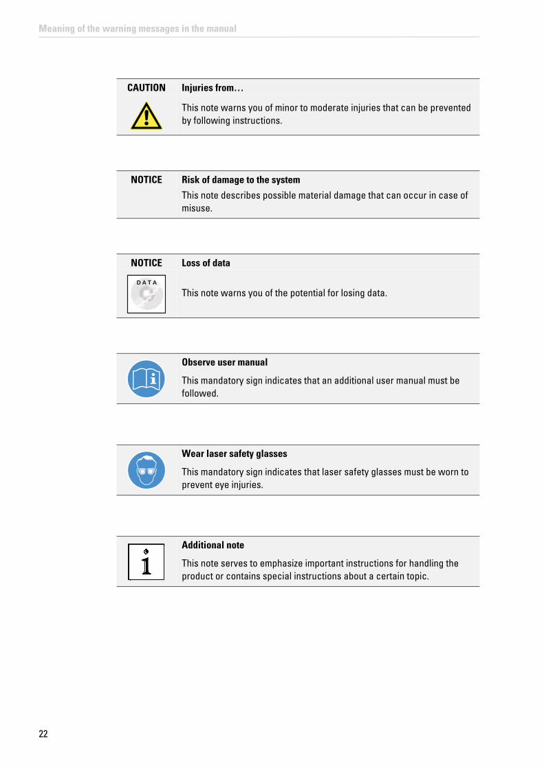
CAUTION Injuries from…
This note warns you of minor to moderate injuries that can be prevented by following instructions.
NOTICE Risk of damage to the system
This note describes possible material damage that can occur in case of misuse.
NOTICE Loss of data
D A T A
This note warns you of the potential for losing data.
Observe user manual
This mandatory sign indicates that an additional user manual must be followed.
Wear laser safety glasses
This mandatory sign indicates that laser safety glasses must be worn to prevent eye injuries.
Additional note
This note serves to emphasize important instructions for handling the product or contains special instructions about a certain topic.
22
Meaning of the warning messages in the manual

23
General Safety Notes
5 General Safety Notes
You have to follow the instructions listed below to work with the instrument safely and without disturbance. If you do not follow these or other instructions in this User Manual or the included manual, Leica Microsystems CMS GmbH shall not be liable for any resulting injury or property damage.
As it is impossible to anticipate every potential hazard, please be careful and apply common sense when using the system.
5.1 Commissioning and Use
• The system components have been packaged securely for transport in multiple crates. Do not open these crates. The crates may be opened and unpacked by Leica service technicians or by people who are authorized by Leica Microsystems CMS GmbH only.
• The system may only be set up by Leica service technicians or by people who are authorized by Leica Microsystems CMS GmbH.
• This laser equipment may be operated only by persons who have been trained in the use of the system and about the potential hazards of laser radiation.
• Have your laser safety officer instruct you about the dangers of laser radiation and about suitable laser safety precautions, such as wearing suitable laser safety glasses. This applies to all persons present in the room where the system is set up and operated.
• Each user must have read the instructions included and follow the instructions it contains.
• Specimens must always be securely fixed in place.
• Do not introduce any flammable objects, such as paper, into the specimen area when you are working with a laser.
• Do not place any flammable or combustible objects on or near the system and do not put it near hot surfaces.
• During start up and during operation, you have to keep your hands and fingers away from the specimen area, as otherwise there is a risk of crushing hazards or injury from rotating objectives and the motorized specimen stage.
• Set up the workplace (for example, chair and monitor) on the system so that it corresponds to your requirements. Observe the national regulations for occupational safety.
• Before each service call by a service technician or whenever you relocate the instrument, you have to clean it thoroughly. This is necessary to remove any possible contamination, thereby preventing the transfer of dangerous substances and pathogens and avoiding hazards and dangers. The same also applies to the removal of components. This applies in particular to systems that are located in biomedical research labs.
• You must not deviate from the operating and maintenance instructions provided herein.

24
General Safety Notes
5.2 Modifications to the System
• The system is installed by service technicians from Leica Microsystems CMS GmbH. You must not change the position of the system components.
• The supply unit must always be set up and operated in an upright position.
• Under no circumstances may you open housing parts.
• Never disconnect a fiber optic cable.
• The cable and fiber optic cable may not be folded, stretched, pinched or rolled up tightly or damaged in any other way.
• The product has a closed liquid coolant circuit. The cooling liquid hoses may not be folded, stretched, pinched or rolled up tightly or damaged in any other way.
• Do not connect any external equipment or other components. If you have questions, please directly contact the Leica branch office in your country.
5.3 Safety Devices and Safety Labels
• So that you can operate the system safely and react quickly and correctly in the event of an emergency, you must familiarize yourself with the safety devices before using it for the first time. Read Chapter "Safety Features" of this User Manual carefully.
• Never remove the safety devices on the system.
• Never deactivate the laser protection devices.
• All safety devices must be ready to operate. Do not carry out any procedures that modify, disable or damage the functionality of safety features. Unauthorized procedures could result in serious injuries or property damage.
• Safety labels on the system may not be removed. Missing or damaged safety labels must be attached immediately and at the described location. Observe Chapter "Safety Labels on the System".
5.4 Laser Safety
• The instrument is a Class 3B/IIIb (VIS and UV lasers) or a Class 4/IV (IR lasers) laser product.
• You must observe all suitable safety measures applicable for this laser class.
• When using an MP system, you must wear laser safety glasses (Order No.: 158002570). Appropriate laser safety glasses for IR laser radiation are provided with the system when delivered. During the scanning operation, all persons present in the room must wear such laser safety glasses. These laser safety glasses do not provide any protection against visible laser radiation (visible spectrum)!
• It is not necessary to wear protective eyewear when using VIS and UV lasers. When used as intended and safety notes have been followed, laser radiation is kept within the limit value that eliminates the chance for eye injuries.
• Never look directly into a laser beam or a reflection of the laser beam. Avoid all contact with the laser beam.

25
General Safety Notes
• Never expose your eyes or skin to direct or indirect laser radiation. The radiation can cause irreparable eye and skin injuries.
• During the scanning operation, the laser radiation is accessible in the microscope's specimen area without obstruction after coming out of the objective. Always maintain a nominal ocular hazard distance of at least 20 cm (8") between your eyes and the opening of the objective.
Figure 1: Specimen area of upright and inverted microscope
• Make sure that the fiber optic cables are not damaged. The system may not be turned on with damaged fiber optic cables, as laser radiation can escape and lead to irreparable eye and skin injuries.
• It is not necessary to wear protective eyewear when using VIS and UV systems. When used as intended and safety notes have been followed, laser radiation is kept within the limit value that eliminates the chance for eye injuries.
• Do not use an S70 microscope condenser. The large working distance and the low numerical aperture of the S70 microscope condenser could result in a hazard from laser radiation.
• Only use S1 and S28 Leica microscope condensers.
• Do not look into the eyepieces during the scanning operation.
• Never change samples during a scanning operation.
• Never change objectives, filter cubes, beam splitters, condensers or other components during a scanning operation.
• Do not look into the eyepieces when switching the beam path in the microscope.
• Do not introduce any reflective objects or mirrors into the laser beam path or into the specimen area.
• If there is no lamp housing or mirror housing connected to the microscope, attach the cover to the replacement flange.
• All unoccupied positions in the objective nosepiece must be closed using the supplied caps.
• For MP systems, dry objectives (air objectives) may not be used with a numerical aperture (NA) larger than 0.85. This does not apply to immersion objectives (oil, water).

26
General Safety Notes
5.5 Electrical Safety
• This system is designed for connection to grounded (earthed) outlets. The grounding plug performs an important safety function. To avoid the risk of electrical shock or damage to the instrument, do not disable this feature. Operation without grounded sockets is not permitted.
• Make sure that the supply voltage at the system remains in an approved tolerance range (100 V~ - 240 V~ ±10%).
• The system may be connected to a power supply with ground protection conductor only! Do not interfere with the grounding function by using an extension cord without a ground wire. Any interruption of the ground wire inside or outside of the system, or release of the ground wire connection, can cause the system to become hazardous. Intentionally disconnecting the ground protection conductor is not permitted.
• Before any cleaning or servicing, de-energize the entire system. To do so, use the power switches of all components and disconnect all power cables from the power supply.
• Only use the power cable included or provided by your local Leica service technicians for connecting individual peripheral devices to the power supply.
• Fuses inside the system may be replaced only by authorized Leica service employees. If you have any further questions, please directly contact the Leica branch office in your country.
• Check that the actual line voltage corresponds to the value configured on the PDL-800-B or D laser driver.
5.6 Contact with Liquids
• To avoid the risk of electrical shock and fire hazards, never expose the system to rain or moisture.
• Do not allow any liquid to enter the system housing or come into contact with any electrical components.
• Avoid condensation.
• The system must be completely dry before connecting it to the power supply or turning it on.
• Do not operate the system if coolant is leaking or has leaked.
5.7 Malfunction of the System
You must immediately disconnect the system from the power supply if any of the following occur:
• The emission warning indicator is not lit after being switched on using the detachable-key switch.
• The indicator continues to be lit after being switched off using the keyswitch
• Scanning of the specimen is not activated after being switched on properly (laser radiation in the specimen area).

27
General Safety Notes
If any of these occur, immediately notify the Leica branch office in your country or your local contact person.

28
General Safety Notes

29
Additional Notes on Handling the System
6 Additional Notes on Handling the System
Follow these instructions to ensure that you handle the system without interference to avoid damage to the instrument and loss of data.
6.1 Location
• You need sufficient space for temporary storage and for unpacking the delivered components. Always protect the transport crates and their contents from moisture and condensation and store them facing upwards (see the indication on the crate).
• Upon receiving the crates, make sure they are intact. If you find that the crates or seals have been damaged, have the supplier confirm this; inform your contact person at Leica Microsystems about this immediately.
• Keep the packaging material in case you need to return a defective component.
• Be absolutely certain to observe the ambient conditions applicable for this system.
• You may use the system indoors only.
• The room must be free of dust, oil and chemical vapors.
• After installing the system, you may carry out interior finish work on the room only if the system is stored in a dust-free location while this work is underway.
• Avoid direct sunlight and vibrations, since these can distort measurements and micrographic scans.
• We recommend using a room that can be completely darkened.
• Do not expose the system to drafts.
• If the system has to be moved to a new location for any reason, contact the Leica branch office in your country.
6.2 Using the Software
• Before carrying out operating steps with the system, first read the corresponding description of the function in LAS AF Online Help. For an overview of the individual functions, refer to the table of contents of the online help.
• Back up your data regularly to a suitable data carrier.
• Do not install any hardware or software on the workstation, as otherwise serious damage to the system or loss of data can result.

30
Additional Notes on Handling the System
• Do not switch the workstation off after a software crash, but restart the LAS AF softwareafter 15 seconds. No image data are lost in case of a software crash. If the LAS AF software is restarted without restarting the workstation, the data are automatically restored. If the software crash is caused by a crash of the workstation, the image data will be lost.
6.3 Protecting the System
• Observe the maintenance instructions and intervals prescribed in the Chapter "Maintenance".
• During the update of the firmware, a continuous tone sounds. After the updated component is automatically restarted, the signal stops. During the automatic update and the automatic restart of the component, you may not switch off or restart the system, since otherwise this can lead to damage to the system.
• Protect the system from dust and grease.
• Make sure to use only one small drop of immersion fluid. The immersion fluid may not contaminate or enter the microscope.
• Make sure that the specimen carrier is not against the objective and cannot be damaged by it or cause broken glass.
• Be absolutely certain to prevent the optics and mechanical parts from coming into direct contact with acids, bases and other aggressive chemicals.
• Never use abrasive products to clean the system and its components. Abrasives can scratch the surface and thus have a negative effect on the protection of the parts.
• Protect the microscope from excessive temperature fluctuations. Such fluctuations can lead to the accumulation of condensation, which can damage the electrical and optical components.
• Allow the entire system to cool down to room temperature before covering the system with a dust cover. This prevents condensation from forming below it, which can enter the system and damage it.
• When used as intended, the HyD reflected light detectors are sufficiently protected from destruction due to overexposure by measures in LAS AF and by an electronic protective circuit. An audible signal (beep) warns the user if the detector is being operated near the maximum permitted signal level. If the maximum permitted signal level is exceeded, the detector automatically switches off and the red status LED on the detector module (see Chapter 13.3, Figure 81, item 2) lights up.
• APDs are extremely sensitive detectors which can be damaged irreparably by light that is too intense (such as room lighting). For this reason, APDs are protected by an automatic shut-off. If the light that falls on the APDs is too intense, they are switched off for a few seconds and an audible warning signal is emitted. The APDs are automatically reactivated after a few seconds. Either switch off the APDs or reduce the light intensity (e.g. by reducing the light intensity of the laser).
• To protect the counting units, never connect or disconnect any cable while the data acquisition and control electronics are activated. Charged signal cables can destroy the instruments.
• Protect the photodetectors (APD or photomultiplier), particularly from excessive light intensity, such as that from the microscope illumination, unattenuated backscatter

31
Additional Notes on Handling the System
excitation etc.
• If you have any further questions, please directly contact the Leica branch office in your country (see Chapter "Contact").
6.3.1 Objectives
• Only use immersion fluids that are intended for the objective. Unsuitable immersion fluid can contaminate or destroy the objective.
• When changing over from an oil or water objective to a dry objective, you have to remove the immersion medium from the specimen slide in order not to damage the dry objective.
• Never open the objectives for cleaning.
• If there is a piezo focus installed on your system, be absolutely certain to observe the corresponding notes in Chapter "Piezo Focus on Upright Microscope".

32
Additional Notes on Handling the System

33
System Overview and Properties
7 System Overview and Properties
7.1 TCS SP8 SMD System Variants
7.1.1 TCS SP8 SMD System Components
Figure 2: System components using the TCS SP8 SMD with upright microscope and flexible supply unit as an example
1 Trolley with external lasers, detectors and their controllers
8 TCS SP8 workstation
9 Main switch board on the supply unit
2 SMD workstation 10 Control panel
3 Fluorescence lamp EL6000 11 KVM switch
4 Multifunction port (MFP) on the scan head 12 SmartMove (only with motorized table)
5 Scan head 13 Upright microscope
6 X1 port on the scan head 14 Microscope electronics box
7 Monitors

34
System Overview and Properties
7.1.2 TCS SP8 SMD with Upright Microscope
Figure 3: Dimensions of TCS SP8 SMD with upright microscope and flexible supply unit
7.1.3 TCS SP8 SMD with Inverted Microscope
Figure 4: TCS SP8 SMD dimensions with inverted microscope and flexible supply unit

35
System Overview and Properties
7.2 TCS SP8 SMD System Variants with White Light Laser
7.2.1 TCS SP8 SMD System Components with White Light Laser
Figure 5: System components using the TCS SP8 SMD with white light laser, upright microscope and PicoQuant laser as an example
1 Trolley with external lasers, detectors and their controllers
8 TCS SP8 workstation
9 Main switch board on the supply unit
2 SMD workstation 10 Control panel
3 Fluorescence lamp EL6000 11 KVM switch
4 Multifunction port (MFP) on the scan head 12 SmartMove (only with motorized table)
5 Scan head 13 Upright microscope
6 X1 port on the scan head 14 Microscope electronics box
7 Monitors 15 White light laser

36
System Overview and Properties
7.2.2 TCS SP8 SMD with White Light Laser and Upright Microscope
Figure 6: Dimensions of TCS SP8 SMD with white light laser, upright microscope, and PicoQuant laser
Figure 7: Dimensions of TCS SP8 SMD with white light laser and upright microscope, without PicoQuant laser

37
System Overview and Properties
7.2.3 TCS SP8 SMD with White Light Laser and Inverted Microscope
Figure 8: Dimensions of TCS SP8 SMD with white light laser, inverted microscope and PicoQuant laser
Figure 9: Dimensions of TCS SP8 SMD with white light laser and inverted microscope, without PicoQuant laser

38
System Overview and Properties
7.3 TCS SP8 SMD System Variants with MP Configuration
The system is available with an infrared laser as well. Here, you see the example dimensions for the MP variant with 150 x 120 cm (4'11" x 3'11") optical table. If you should need the dimensions for using a larger table or additional accessories, please look at the Leica TCS SP8 MP Room Requirements.
Figure 10: System overview of TCS SP8 SMD with MP configuration upright and inverted microscope possible
1 Trolley with external lasers, detectors and their controllers
5 Optical table, 150 x 120 cm (4'11" x 3'11")
6 Upright or inverted microscope
2 SMD workstation 7 Beam coupling unit
3 Microscope electronics box + EL6000 fluorescence lamp
8 Infrared (IR) laser
9 Power supply and cooling of the IR laser
4 Stage with supply unit (compact or flexible)
39
System Overview and Properties
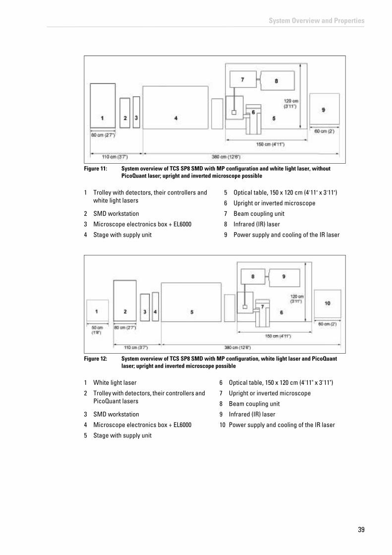
Figure 11: System overview of TCS SP8 SMD with MP configuration and white light laser, without PicoQuant laser; upright and inverted microscope possible
Figure 12: System overview of TCS SP8 SMD with MP configuration, white light laser and PicoQuant laser; upright and inverted microscope possible
1 Trolley with detectors, their controllers and white light lasers
5 Optical table, 150 x 120 cm (4'11" x 3'11")
6 Upright or inverted microscope
2 SMD workstation 7 Beam coupling unit
3 Microscope electronics box + EL6000 8 Infrared (IR) laser
4 Stage with supply unit 9 Power supply and cooling of the IR laser
1 White light laser 6 Optical table, 150 x 120 cm (4'11" x 3'11")
2 Trolley with detectors, their controllers and PicoQuant lasers
7 Upright or inverted microscope
8 Beam coupling unit
3 SMD workstation 9 Infrared (IR) laser
4 Microscope electronics box + EL6000 10 Power supply and cooling of the IR laser
5 Stage with supply unit

40
System Overview and Properties
7.4 Controls on the Supply Unit
7.4.1 Main Switch Board on the Flexible Supply Unit
Figure 13: Overview of the main switch board on the flexible supply unit
7.4.2 Control Panel Field on the Compact Supply Unit (Only for FLIM)
Figure 14: Overview of the control panel field on the Compact supply unit

41
System Overview and Properties
7.5 Technical Data
7.5.1 Dimensions
7.5.2 Weight
Dimensions of the system (length x depth x height)
TCS SMD for TCS SP8 with upright microscope, compact and flexible supply unit possible
350 x 120 x 175 cm (11'6" x 3'11" x 5'9")
TCS SMD for TCS SP8 with inverted microscope, compact and flexible supply unit possible
364 x 120 x 150 cm (11'11" x 3'11" x 4'11")
TCS SMD for TCS SP8 X with upright microscope and PicoQuant laser
400 x 120 x 175 cm (13'1" x 3'11" x 5'9")
TCS SMD for TCS SP8 X with upright microscope without PicoQuant laser
350 x 120 x 175 cm (11'6" x 3'11" x 5'9")
TCS SMD for TCS SP8 X with inverted microscope and PicoQuant laser
414 x 120 x 150 cm (13'7" x 3'11" x 4'11")
TCS SMD for TCS SP8 X with inverted microscope without PicoQuant laser
364 x 120 x 150 cm (11'11" x 3'11" x 4'11")
TCS SMD for TCS SP8 MP max. 490 x 120 x 175 cm (16'1" x 3'11" x 5'9")
TCS SMD for TCS SP8 X with MP configuration without PicoQuant laser
max. 490 x 120 x 175 cm (16'1" x 3'11" x 5'9")
TCS SMD for TCS SP8 X with MP configuration and PicoQuant laser
max. 540 x 120 x 175 cm (17'9" x 3'11" x 5'9")
Dimensions of the supply unit (length x depth x height)
Compact Supply Unit 38 x 54 x 50 cm (1'3" x 1'9" x 1'8")
Flexible Supply Unit 110 x 70 x 90 cm (3'7" x 2'4" x 2'11")
Weight of the basic TCS SP8 system 330 kg (728 lbs) maximum
Weight of the MP components Approx. 380 kg (838 lbs)
Weight of the SMD components 160 kg (353 lbs) maximum
Weight of the white light laser 35 kg (77 lbs)

42
System Overview and Properties
7.5.3 Electrical Specifications
You can find more information on electrical connection requirements in Chapter 8.4 and in Chapter 8.5.
Observe the user manuals for external lasers
Please refer to the information from the documents provided by the laser manufacturer for the external lasers. Pay particular attention to the laser manufacturer's notes!
7.6 "Electromagnetic Compatibility"
In regards to emitted interference, this is a class A system (CISPR 11). This system is suitable for use in buildings that do not include domestic premises and buildings not directly connected to a low-voltage power supply network that supplies buildings used for domestic purposes.
The system can cause radio interference in a household environment. In these cases, the operator may have to take measures to eliminate the interference.
When using internal and external HyDs, it is recommended that the system only be operated in a controlled electromagnetic environment. This is because the use of cell phones or other radio transmitting devices such as DECT phones can cause picture interference if used in the immediate vicinity of the system.
Flexible supply unit Compact supply unit White light laser
Supply voltage 100 V~ to 240 V~ ± 10%, grounded
Power consumption 2x 1600 VA (Including peripheral devices connected to
the flexible supply unit's multiple socket outlet,
see Chapter 8.5)
700 VA 400 VA
Fuse LS automated process 2x T8AH, 250 V AC LS automated process for TCS
SP8.2x T4AH, 250 V AC
for white light laser
Protection class I
Type of protection Covered design
Overvoltage category II
Frequency 50/60 Hz

43
System Overview and Properties
7.7 Serial Number
The serial number for your system is located on the rear side of the scan head:
Figure 15: Rear side of the scan head – label with serial number

44
System Overview and Properties

45
Ambient Conditions
8 Ambient Conditions
Here you can find a summary of the information regarding the size and design of the room and the general requirements regarding ambient conditions. Be absolutely sure to comply with the ambient conditions.
8.1 General Requirements Regarding Ambient Conditions
• You may use the system only in indoor areas that are dust-free. The room must be free of dust, oil and chemical vapors.
• Avoid direct sunlight and vibrations, since these can distort measurements and micrographic scans. We also recommend using a room that can be completely darkened.
• The room must meet national safety regulations for laser safety areas.
• Never expose the system to rain, fluids, or humidity. Do not set up the system under water pipes, air-conditioning systems, or other piping. Otherwise, this could cause fire and electrical shocks to the system and the electrical components.
• The room should be equipped with a telephone connection to contact Leica Microsystems CMS GmbH for phone support. For RemoteCare, an Internet connection is also needed.
• The system should be set up in a separate room, in order to be able to provide a constant temperature and appropriate ambient lighting without having to address needs of other systems, instruments, and room users.
Temperature range for operation
18 to 25 °C (64 to 77 °F)
optimum optical behavior 22 °C ± 1 °C (72 °F ± 1.8 °F)
Pollution degree 2 (protect system against dust)
Permitted relative humidity 20 to 60% (non-condensing)
Maximum location elevation 2000 m above sea level
• HyD RLDs are cooled. To ensure optimal performance from the detectors, the humidity of the surrounding air must not exceed 60% at 25°C. To prevent potential damage due to condensation, the cooling shuts off automatically if its value is exceeded.
8.2 Vibrations
Vibrations must be reduced to a minimum; for that reason, do not set up the system near any of the following sources of vibration: shakers, ultracentrifuges, pumps, compressors, refrigerators, vending machines, elevators.
Frequency range [5 Hz – 30 Hz] less than 30 μm/s root mean square
Frequency range [> 30 Hz] less than 60 μm/s root mean square
Maximum tolerable vibrations:

46
Ambient Conditions
8.3 Room Dimensions
The room should be as large as possible so that multiple operators can find room around the system.The free space to the right, left and rear of the system should be 60 cm. In front of the system there must be 110 cm of free space so that the service technicians can access the system as necessary.
WARNING Fire or overheating of the system possible
Electrical peripheral devices must be placed at least 10 cm (4") away from the wall and from flammable substances to prevent overheating or fire of the system.
Also make sure that doors and passages are at least 100 cm wide in order to be able to safely transport the system.
The following minimum size should be planned for the space:
Room dimensions (length x depth)
TCS SP8 SMD with upright microscope, compact and flexible supply unit possible
470 x 290 cm (15'5" x 9'6")
TCS SP8 SMD with inverted microscope, compact and flexible supply unit possible
484 x 290 cm (15'11" x 9'6")
TCS SP8 SMD with white light laser, upright microscope and PicoQuant laser
520 x 290 cm (17'1" x 9'6")
TCS SP8 SMD with white light laser, upright microscope without PicoQuant laser
470 x 290 cm (15'5" x 9'6")
TCS SP8 SMD with white light laser, inverted microscope and PicoQuant laser
534 x 290 cm (17'6" x 9'6")
TCS SP8 SMD with white light laser, inverted microscope without PicoQuant laser
484 x 290 cm (15'11" x 9'6")
TCS SP8 SMD with MP configuration 610 x 290 cm (20' x 9'6")
TCS SP8 SMD with white light laser and MP configuration, without PicoQuant laser
610 x 290 cm (20' x 9'6")
TCS SP8 SMD with white light laser, MP configuration and PicoQuant laser
660 x 290 cm (21'8" x 9'6")

47
Ambient Conditions
8.4 Electrical Connection Requirements
WARNING Electric shock is possible when using ungrounded sockets
This system is designed for connection to grounded (earthed) outlets. The grounding plug performs an important safety function. To avoid the risk of electrical shock or damage to the instrument, do not disable this feature. Operation without grounded sockets is not permitted.
8.4.1 System with Flexible Supply Unit
Supply voltage 100 V~ to 240 V~ ± 10%, grounded
Frequency 50/60 Hz
Power connection Three separate electric circuits withPower supply voltage: 100 V - 120 V, fuse protection: 20 Aor: Power supply voltage: 200 V - 240 V, fuse protection: 12 - 16 A(Two for the flexible supply unit's power supply and one for supplying peripheral devices)
To prevent damage to the instrument, the two types of voltage (200 to 240 V~ and 100 to 120 V~) must not be combined. Depending on the system configuration, further electrical circuits may be required.
Power supply for USA Two terminals of the NEMA 5-20 type for the supply unit Terminals of the NEMA 5-15 type for the remaining instruments
for the SMD rack a separate electric circuit withPower supply voltage: 100 V~ to 240 V~, fuse protection: 16 - 20 A, dependent on local regulations
for the infrared laser and its cooling system (MP configuration)
a separate electric circuit withPower supply voltage: 100 V~ to 240 V~, fuse protection: 12 -16 A, dependent on local regulations
When using HyD RLDs An additional power supply
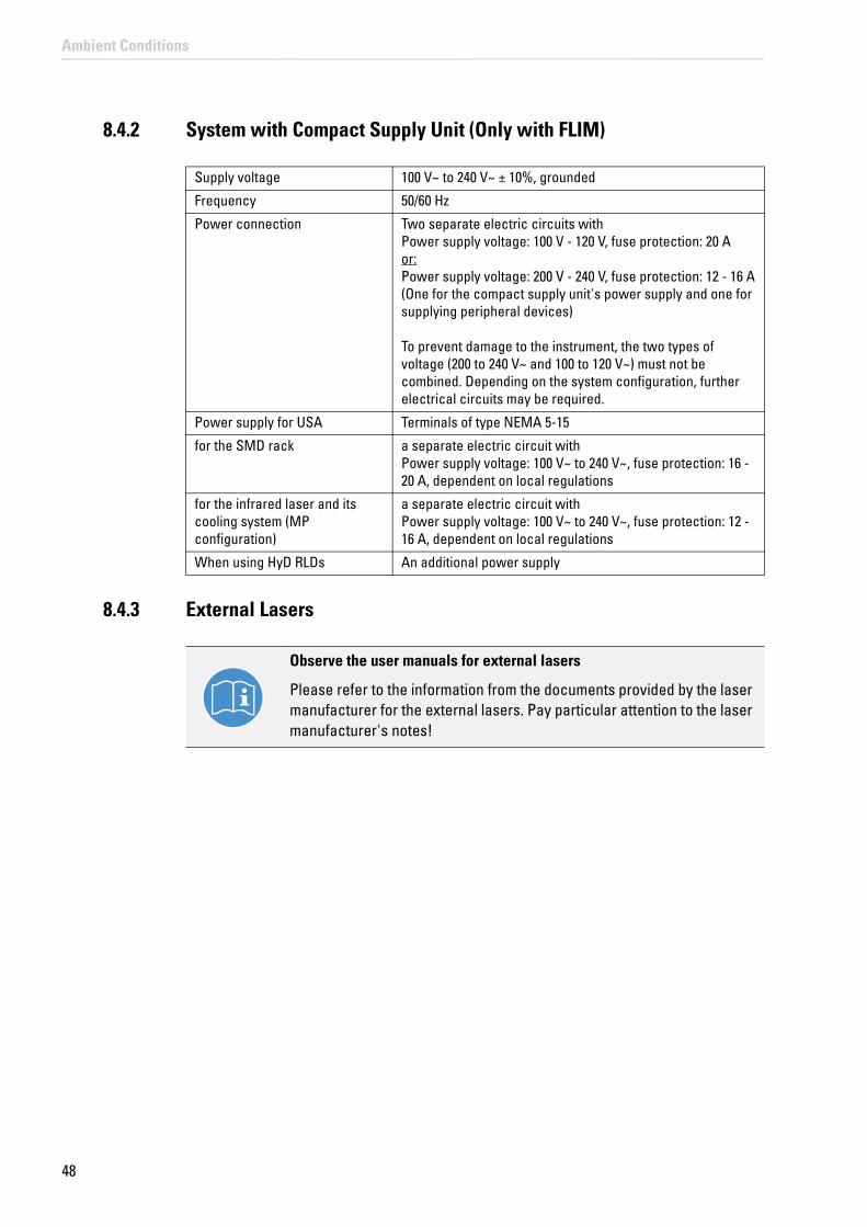
48
Ambient Conditions
8.4.2 System with Compact Supply Unit (Only with FLIM)
Supply voltage 100 V~ to 240 V~ ± 10%, grounded
Frequency 50/60 Hz
Power connection Two separate electric circuits withPower supply voltage: 100 V - 120 V, fuse protection: 20 Aor: Power supply voltage: 200 V - 240 V, fuse protection: 12 - 16 A(One for the compact supply unit's power supply and one for supplying peripheral devices)
To prevent damage to the instrument, the two types of voltage (200 to 240 V~ and 100 to 120 V~) must not be combined. Depending on the system configuration, further electrical circuits may be required.
Power supply for USA Terminals of type NEMA 5-15
for the SMD rack a separate electric circuit withPower supply voltage: 100 V~ to 240 V~, fuse protection: 16 - 20 A, dependent on local regulations
for the infrared laser and its cooling system (MP configuration)
a separate electric circuit withPower supply voltage: 100 V~ to 240 V~, fuse protection: 12 -16 A, dependent on local regulations
When using HyD RLDs An additional power supply
8.4.3 External Lasers
Observe the user manuals for external lasers
Please refer to the information from the documents provided by the laser manufacturer for the external lasers. Pay particular attention to the laser manufacturer's notes!

49
Ambient Conditions
8.5 Load capacity of the multiple socket outlet on the flexible supply unit
The total power consumption of all loads connected to the multiple socket outlet (see Figure 16) must not exceed 800 VA.
The terminals are intended for:
• Workstation
• Monitor
• Microscope
Figure 16: Load capacity on the rear side of the multiple socket outlet on the flexible supply unit
8.6 Waste Heat and Cooling
NOTICE Instruments may sustain damage
Never install the system close to air conditioners or other ventilation systems. Air from air-conditioning systems or other ventilation equipment should not blow directly on the microscope.
Use a high-performance air-conditioning system
We recommend a high-performance air-conditioning system for operating the system to prevent large temperature fluctuations in the room.

50
Ambient Conditions
8.6.1 System with Flexible Supply Unit
Waste heat of the complete system, including the argon laser
Max. of 3.9 kW (VIS system with SMD components)Max. of 6.9 kW (MP system with SMD components)Max. 4.3 kW (WLL and VIS system with SMD components)Max. 7.3 kW (WLL and MP system with SMD components)
Waste heat of the argon laser 1.6 kW
Standard fan about 30 x 30 cm (1' x 1')
Noise-reduced laser fan 50 x 60 cm (1'8" x 2')
Hose length 400 cm (13'1"), provided by default
Diameter of adapter piece 15 cm (6")
Air flow rate 400 m³/h (14,126 ft³/h)
For cooling, the argon laser must be connected to the provided argon laser fan. The following space is required:
In addition, it is possible to connect the argon laser exhaust to an in-house exhaust system:
The remaining waste heat must be extracted; otherwise the room temperature will rise.
8.6.2 System with Compact Supply Unit (Only with FLIM)
Waste heat of the complete system with a compact supply unit
Max. of 2.4 kW (VIS system with SMD components)Max. of 5.4 kW (MP system with SMD components)
8.6.3 External Lasers
Observe the user manuals for external lasers
Please refer to the information from the documents provided by the laser manufacturer for the external lasers. Pay particular attention to the laser manufacturer's notes!
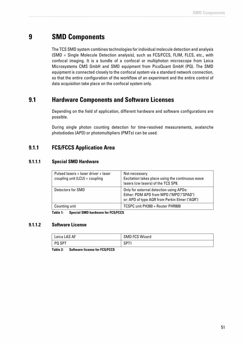
51
SMD Components
9 SMD Components
The TCS SMD system combines technologies for individual molecule detection and analysis (SMD = Single Molecule Detection analysis), such as FCS/FCCS, FLIM, FLCS, etc., with confocal imaging. It is a bundle of a confocal or multiphoton microscope from Leica Microsystems CMS GmbH and SMD equipment from PicoQuant GmbH (PQ). The SMD equipment is connected closely to the confocal system via a standard network connection, so that the entire configuration of the workflow of an experiment and the entire control of data acquisition take place on the confocal system only.
9.1 Hardware Components and Software Licenses
Depending on the field of application, different hardware and software configurations are possible.
During single photon counting detection for time-resolved measurements, avalanche photodiodes (APD) or photomultipliers (PMTs) can be used.
9.1.1 FCS/FCCS Application Area
9.1.1.1 Special SMD Hardware
Table 1: Special SMD hardware for FCS/FCCS
9.1.1.2 Software License
Table 2: Software license for FCS/FCCS
Pulsed lasers + laser driver + laser coupling unit (LCU) + coupling
Not necessary. Excitation takes place using the continuous wave lasers (cw lasers) of the TCS SP8.
Detectors for SMD Only for external detection using APDs: Either: PDM APD from MPD ("MPD"/"SPAD") or: APD of type AQR from Perkin Elmer ("AQR")
Counting unit TCSPC unit PH300 + Router PHR800
Leica LAS AF SMD FCS Wizard
PQ SPT SPT1

52
SMD Components
9.1.2 FLIM Application Area
9.1.2.1 Special SMD Hardware
Table 3: Pulsed lasers, laser driver, laser coupling units and coupling for FLIM
Table 4: Special SMD hardware for FLIM
9.1.2.2 Software License
Table 5: Software license for FLIM
Pulsed lasers Laser driver Laser coupling unit (LCU)
Coupling
405 nm PDL800-B or -D via UV port in scan head
440 nm PDL800-B via MFP in scan head
440 nm + 470 nm Sepia I LCU II via MFP in scan head
470 nm PDL800-B via MFP in scan head
470 nm + 640 nm Sepia I LCU II via MFP in scan head
405 nm + 470 nm + 640 nm
Sepia II LCU II via UV port and MFP in scan head
WLL via AOBS
MP (with TDA - trigger diode assembly))
via MFP
Detectors for SMD External detection on the X1 port:Either: PDM APD from MPD ("MPD") + DSN102 or: PMA photomultiplier
And/or internal detection:SP FLIM photomultiplier (within spectral module)Or external detection at the NDD position with MP FLIM excitation: HyD RLD
Counting unit TCSPC unit PH300 + with multiple detectors: Router PHR800
Leica LAS AF SMD FLIM Wizard
PQ SPT SPT2

53
SMD Components
9.1.3 Application area FCS/FCCS, FLIM, FLCS, gated FCS
9.1.3.1 Special SMD Hardware
Table 6: Special SMD hardware for FCS/FCCS, FLIM, FLCS, gated FCS
9.1.3.2 Software License
Table 7: Software license for FCS/FCCS, FLIM, FLCS, gated FCS
9.2 Beam Path
The fluorescence necessary for SMD measurement is excited by means of lasers, which are coupled into the scan head. For FCS and FCCS, continuous wave (cw) lasers are normally used. However, pulsed lasers can also be used. For FLIM, FLCS or gated FCS, only pulsed lasers can be used.
The excitation light reaches the specimen through the scan head. The light is collected by the objective and passes through the scan head to the SMD detectors that can be either within the spectral module in the scan head or outside the scan head.
For SMD, special detectors are needed that work in single photon counting mode and have a low background signal. For FLIM, additionally, a high time resolution is necessary, whereas for FCS a high quantum efficiency is crucial. Therefore, different detectors can be used, depending on the field of application (see Table 1, Table 4 and Table 6).
When confocal, external detectors are used, light is split off to optical fibers at the external interface X1 ("X1 port") with the aid of the X1 adapter, then guided to the photodetectors via multimode waveguides (Figure 17). These waveguide fibers enable the scan head to be mechanically decoupled from the detectors. If two external detectors are used, light is split by a beam splitter into the two detection channels. The beam splitter is situated in the SMD filter cube that is placed in the X1 port adapter on the X1 port.
Pulsed lasers + laser driver + laser coupling unit (LCU) + coupling as with MP-FLIM
Detectors for SMD
External detection:PDM APD from MPD ("MPD") + DSN102And/or internal detection:SP FLIM photomultiplier (within spectral module, used for spectral FLIM)
Counting unit TCSPC unit PH300 + Router PHR800
Leica LAS AF FCS Wizard + FLIM Wizard
PQ SPT SPT1+2
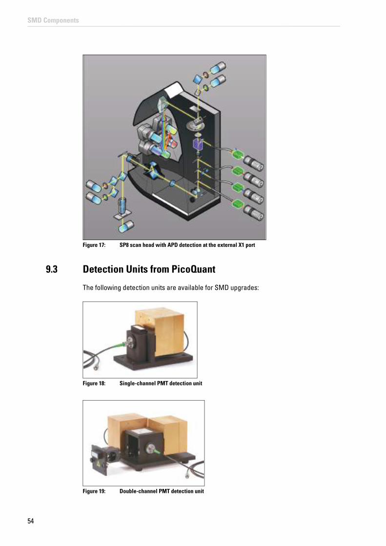
54
SMD Components
Figure 17: SP8 scan head with APD detection at the external X1 port
9.3 Detection Units from PicoQuant
The following detection units are available for SMD upgrades:
Figure 18: Single-channel PMT detection unit
Figure 19: Double-channel PMT detection unit

55
SMD Components
Figure 20: Single-channel APD detection unit
Figure 21: Double-channel APD detection unit
Chapter 23 includes instructions for replacing the filter cube in the X1 port adapter that splits the emission light onto the two APDs.
9.4 Leica APD Detector Unit
Two APDs (of type AQR from Perkin Elmer) are located in the Leica APD detector unit (Figure 22). They are linked to the X1 port adapter on the scan head using optical fibers. At the APD detector unit, the APDs can be switched on independently of one another (Figure 22, item 1 and 2). In addition to the switches for the APDs, the front side of the control unit also includes indicators for the power supply (Figure 22, item 3). The power switch itself is on the rear of the APD detector unit (Figure 22, item 5).
Figure 22: Leica APD detector unit
The photon counting signal generated by the APDs is recorded by the PicoHarp 300 and analyzed by a second workstation using SymPhoTime software.
Chapter 23 includes instructions for replacing the filter cube in the X1 port adapter that splits the emission light onto the two APDs.
56
SMD Components
9.4.1 General Precautionary Measures for Using APD Detector Units
• Never switch the APDs on with a light source switched on. To prevent inadvertent illumination of the APDs, in the Leica LASAF software, place the external port (X1 Port)in Beam Path Settings in the LAS AF software in the mirror position (see Chapter 16.1.1 and Chapter 18.2.1) before you switch on the APDs.
• Do not switch the APDs on until just before they are to be used. They require about 30-60 seconds before they are ready for operation. Always switch the APDs off again after use.
• The APDs can be switched on independently of one another. Only switch on the APD(s) that you really need.
• As far as possible, avoid working in reflection. In order to work in fluorescence mode, switch the AOBS to fluorescence. For the excitation, select laser lines that are outside the detection zones defined by the filter cube. Switch the APDs off before you change the filter cube.
9.4.2 Changing the Fuse
The fuse is in the device connector on the back of the APD detector unit. When replacing the fuse, there must be no voltage at the APD detector unit (disconnect the mains plug).
9.4.3 Safety Shutoff
APDs are extremely sensitive detectors which can be damaged irreparably by light that is too intense (such as room lighting). For this reason, APDs are protected by an automatic shut-off. If the light that falls on the APDs is too intense, they are switched off for a few seconds and an audible warning signal is emitted. The APDs are automatically reactivated after a few seconds.
If you hear the audible warning signal, either switch off the APDs or reduce the light intensity that reaches the APDs (e.g. by reducing the light intensity of the laser).
9.5 Trigger Unit
The trigger unit transfers electronic signals (like frame and line clocks for FLIM images) from the SP8 scan head to the TCSPC counting device.
NOTICE Light that is too intense may damage the APDs
Prevent a light intensity that is too high (due to too high laser intensity or room illumination) on the APDs. Otherwise, the detectors can be damaged irreparably.

57
SMD Components
Figure 23: Front side of the trigger unit
Figure 24: Rear side of the trigger unit
9.6 Laser Coupling Unit (LCU)
In the laser coupling unit (LCU), there are up to four pulsed lasers. It combines and couples one or more pulsed VIS laser beams (e.g. 440 nm up to 640 nm) into a polarization-maintaining single mode (PM-SM) laser (Figure 25). This laser is coupled into the multifunction port (MFP) of the SP8 scan head.
In the UV range (e.g. 405 nm) a separate laser output is used that is coupled to the UV port of the SP8 scan head.
Figure 25: Laser Coupling Unit (LCU)
WARNING Risk of permanent eye and skin damage from laser radiation
The laser coupling unit must not be opened. The adjustment of the laser beam and the coupling must be carried out by a service technician.

58
SMD Components
9.6.1 Attenuation Unit
The laser coupling module contains an attenuation unit which enables a graduated and continuous intensity attenuation via two different elements: a filter wheel and a scaffold (Figure 26).
Using the filter wheel, the attenuation is adjustable in three steps (between four positions) by replacing the filter in the beam paths:
• 0 = 100 % transmission
• 1 = 10 % transmission
• 2 = 1 % transmission
• 3 = 0.1 % transmission
The additional scaffold allows a continuous attenuation (100 % to 0 %) by clipping the laser beams. The scaffold is controlled by a micrometer screw and enables precision control of the intensity.
Note that the attenuation unit is placed in a position where all laser beams come through. This ensures that the attenuation of the ND filters (neutral density filters) is equal for all beams. However, the attenuation achieved with the scaffold can be different for the specific laser beams due to differences in the shape and orientation of the beam profile.
Figure 26: Attenuation unit with filter wheel and scaffold.
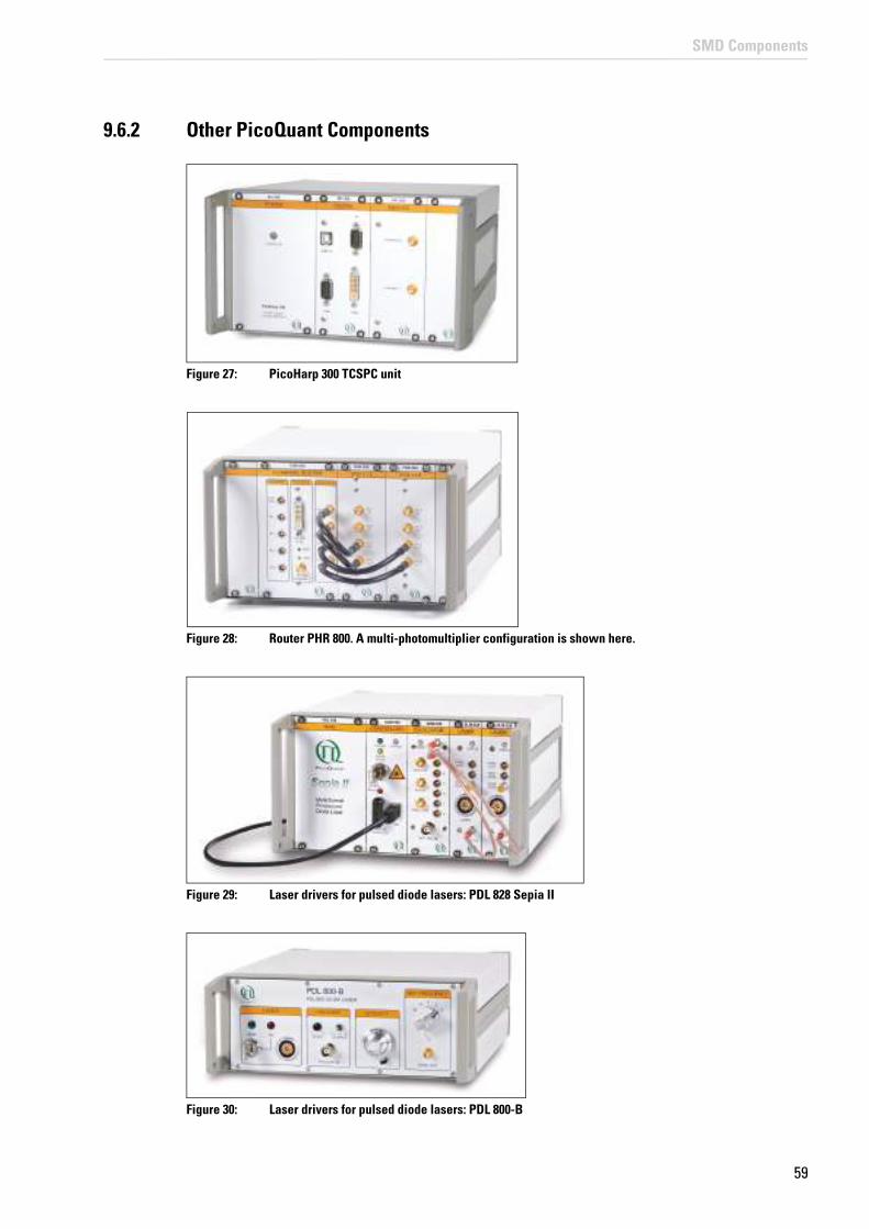
59
SMD Components
9.6.2 Other PicoQuant Components
Figure 27: PicoHarp 300 TCSPC unit
Figure 28: Router PHR 800. A multi-photomultiplier configuration is shown here.
Figure 29: Laser drivers for pulsed diode lasers: PDL 828 Sepia II
Figure 30: Laser drivers for pulsed diode lasers: PDL 800-B

60
SMD Components
Figure 31: DSN 102 Dual SPAD Power Supply

61
Laser
10 Laser
It is mandatory to observe the laser safety measures for laser class 3B / IIIb (VIS and UV lasers) or for laser class 4 / IV (MP systems) in accordance with applicable national and federal regulations.
You may only use the laser listed here, as the laser safety devices are only designed for the laser variants listed here.
10.1 Laser Classes
System variant System variant laser class
Usable lasers
Wavelength range
TCS SP8 SMD 3B / IIIbVIS 400 - 700 nm (visible laser radiation)
UV 350 - 400 nm (invisible laser radiation)
TCS SP8 SMD with WLL 3B / IIIb
VIS 400 - 700 nm (visible laser radiation)
UV 350 - 400 nm (invisible laser radiation)
TCS SP8 SMD with MP configuration
4 / IV
VIS 400 - 700 nm (visible laser radiation)
UV 350 - 400 nm (invisible laser radiation)
IR 680 - 1600 nm (invisible laser radiation)
10.2 Overview of Usable Lasers for Image Acquisition
10.2.1 VIS/UV Lasers for TCS SP8
The TCS SP8 features a combination of the lasers listed below:
Laser type Wavelength (nm)
Maximum light output at laser output (mW)
Maximum light output in focal plane (mW)
Pulse duration
UV, external 355 < 500 < 18 Continuous wave (cw)
Diode 405 405 < 120 < 7 Continuous wave (cw)
Diode 405 p 405 < 5 (mean power)
< 0.3 (mean power)
pulsed, 60 ps
Diode 442 442 < 75 < 7 Continuous wave (cw)
Diode 448 448 100 10 Continuous wave (cw)
Ar 458, 476, 488, 496, 514
< 200 < 50 Continuous wave (cw)
OPSL 488 488 350 10 Continuous wave (cw)

62
Laser
10.2.2 VIS/UV Lasers for TCS SP8 X
The TCS SP8 X features a combination of the lasers listed below:
10.2.3 IR lasers for TCS SP8 MP
The TCS SP8 MP can include a combination of all of the lasers listed in Chapter 10.2.1 and Chapter 10.2.2 - except for the external UV laser (355 nm) - and the following IR lasers:
10.2.3.1 Picosecond laser
Laser type Wavelength (nm)
Maximum light output at laser output (W)
Maximum light output in focal plane (W)
Pulse duration
MaiTai HP ps 690 - 1040 < 3,5 < 1,9 pulsed, 1.0 - 1.5 ps
Chameleon Ultra II ps 680 - 1080 < 4 < 1,9 pulsed, 1.0 - 1.5 ps
OPSL 514 514 350 10 Continuous wave (cw)
OPSL 552 552 350 10 Continuous wave (cw)
DPSS 561 561 < 100 < 12 Continuous wave (cw)
HeNe 594 < 4 < 1 Continuous wave (cw)
HeNe 633 < 15 < 5 Continuous wave (cw)
Diode 638 638 350 10 Continuous wave (cw)
Laser type Wavelength (nm)
Maximum light output at laser output (mW)
Maximum light output in focal plane (mW)
Pulse duration
Diode 405 405 < 120 < 7 Continuous wave (cw)
Diode 405 p 405 < 5 (mean power)
< 0.3 (mean power)
pulsed, 60 ps
UV, external 355 < 500 < 18 Continuous wave (cw)
Ar 458, 476, 488, 496, 514
< 200 < 50 Continuous wave (cw)
White light laser 470 – 670 < 500 < 50 Pulsed

63
Laser
10.2.3.2 Femtosecond laser
Laser type Wavelength (nm)
Maximum light output at laser output (W)
Maximum light output in focal plane (W)
Pulse duration
MaiTai fs 780 - 920 < 1,2 < 0,6 pulsed ~ 80 fs
MaiTai HP fs 690 - 1040 < 3,5 < 1,9 pulsed ~ 100 fs
MaiTai HPDeep See
690 - 1040 < 3,5 < 1,9 pulsed ~ 100 fs
MaiTai eHPDeep See
690 - 1040 < 3,5 < 1,9 pulsed ~ 70 fs
Chameleon Ultra I fs 690 - 1040 < 4 < 1,9 pulsed ~ 140 fs
Chameleon Ultra II fs 680 - 1080 < 4 < 1,9 pulsed ~ 140 fs
ChameleonVision II
680 - 1080 < 4,0 < 1,9 pulsed ~ 140 fs
ChameleonVision S
690 - 1050 < 3,5 < 1,9 pulsed ~ 75 fs
Chameleon Ultra II Compact OPO
680 - 1080 < 4,0 < 1,9 pulsed ~ 140 fs
1000 - 1300 < 1,6 < 0,8 pulsed > 100 fs
Chameleon Vision II Compact OPO
680 - 1080 < 4,0 < 1,9 pulsed ~ 140 fs
1000-1280 < 1,6 < 0,8 pulsed > 100 fs
10.3 Overview of Usable Lasers for FCS
10.3.1 VIS/UV Lasers for TCS SP8 SMD
Laser type Wavelength (nm)
Maximum light output at laser output (mW)
Maximum light output in focal plane (mW)
Pulse duration
Ar 458, 476, 488, 496, 514
< 200 < 50 Continuous wave (cw)
DPSS 561 561 < 100 < 12 Continuous wave (cw)
HeNe 594 < 4 < 1 Continuous wave (cw)
HeNe 633 < 15 < 5 Continuous wave (cw)
Diode 638 638 350 10 Continuous wave (cw)
White light laser 470 – 670 < 500 < 50 Pulsed
The TCS SP8 SMD (for FCS) features a combination of the lasers listed below:

64
Laser
10.4 Overview of usable lasers for FLIM
10.4.1 VIS/UV Lasers for TCS SP8 SMD
Laser type Wavelength (nm)
Maximum light output at laser output (mW)
Maximum light output in focal plane (mW)
Pulse duration
405 pulsed 405 3 @ 40 MHz 0.1 @ 40 MHz pulsed, >80 ps
405 dual-voltage 405 3 @ 40 MHz 0.1 @ 40 MHz Pulsed + continuous wave (cw) >80 ps
440 440 3 @ 40 MHz 0.1 @ 40 MHz pulsed, >80 ps
470 470 3 @ 40 MHz 0.3 @ 40 MHz pulsed, >80 ps
640 640 4.5 @ 40 MHz 0.5 @ 40 MHz pulsed, >80 ps
White light laser 470 – 670 < 500 < 50 Pulsed
The TCS SP8 SMD (for FLIM) features a combination of the lasers listed below:
10.4.2 Infrared Lasers for TCS SP8 SMD with MP Configuration
The TCS SP8 SMD with MP configuration (for FLIM) can contain a combination of all the infrared lasers in Chapter 10.4.1 and the following infrared lasers:
10.4.2.1 Picosecond laser
Laser type Wavelength (nm)
Maximum light output at laser output (W)
Maximum light output in focal plane (W)
Pulse duration
MaiTai HP ps 690 - 1040 < 3,5 < 1,9 pulsed, 1.0 - 1.5 ps
Chameleon Ultra II ps 680 - 1080 < 4 < 1,9 pulsed, 1.0 - 1.5 ps
10.4.2.2 Femtosecond laser
Laser type Wavelength (nm)
Maximum light output at laser output (W)
Maximum light output in focal plane (W)
Pulse duration
MaiTai fs 780 - 920 < 1,2 < 0,6 pulsed ~ 80 fs
MaiTai HP fs 690 - 1040 < 3,5 < 1,9 pulsed ~ 100 fs
MaiTai HPDeep See
690 - 1040 < 3,5 < 1,9 pulsed ~ 100 fs
MaiTai eHPDeep See
690 - 1040 < 3,5 < 1,9 pulsed ~ 70 fs
Chameleon Ultra I fs 690 - 1040 < 4 < 1,9 pulsed ~ 140 fs
Chameleon Ultra II fs 680 - 1080 < 4 < 1,9 pulsed ~ 140 fs

65
Laser
ChameleonVision II
680 - 1080 < 4,0 < 1,9 pulsed ~ 140 fs
ChameleonVision S
690 - 1050 < 3,5 < 1,9 pulsed ~ 75 fs
Chameleon Ultra II Compact OPO
680 - 1080 < 4,0 < 1,9 pulsed ~ 140 fs
1000 - 1300 < 1,6 < 0,8 pulsed > 100 fs
Chameleon Vision II Compact OPO
680 - 1080 < 4,0 < 1,9 pulsed ~ 140 fs
1000-1280 < 1,6 < 0,8 pulsed > 100 fs

66
Laser
10.5 Overview of Usable Lasers for FLCS
10.5.1 VIS/UV Lasers for TCS SP8 SMD
Laser type Wavelength (nm)
Maximum light output at laser output (mW)
Maximum light output in focal plane (mW)
Pulse duration
405 pulsed 405 3 @ 40 MHz 0.1 @ 40 MHz pulsed, >80 ps
405 dual-voltage 405 3 @ 40 MHz 0.1 @ 40 MHz Pulsed + continuous wave (cw) >80 ps
440 440 3 @ 40 MHz 0.1 @ 40 MHz pulsed, >80 ps
470 470 3 @ 40 MHz 0.3 @ 40 MHz pulsed, >80 ps
640 640 4.5 @ 40 MHz 0.5 @ 40 MHz pulsed, >80 ps
White light laser 470 – 670 < 500 < 50 Pulsed
The TCS SP8 SMD (for FLCS) features a combination of the lasers listed below:
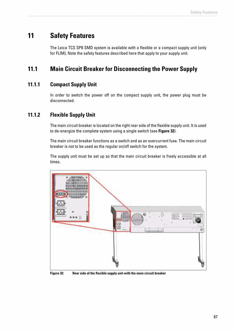
67
Safety Features
11 Safety Features
The Leica TCS SP8 SMD system is available with a flexible or a compact supply unit (only for FLIM). Note the safety features described here that apply to your supply unit.
11.1 Main Circuit Breaker for Disconnecting the Power Supply
11.1.1 Compact Supply Unit
In order to switch the power off on the compact supply unit, the power plug must be disconnected.
11.1.2 Flexible Supply Unit
The main circuit breaker is located on the right rear side of the flexible supply unit. It is used to de-energize the complete system using a single switch (see Figure 32).
The main circuit breaker functions as a switch and as an overcurrent fuse. The main circuit breaker is not to be used as the regular on/off switch for the system.
The supply unit must be set up so that the main circuit breaker is freely accessible at all times.
Figure 32: Rear side of the flexible supply unit with the main circuit breaker

68
Safety Features
11.1.3 Other Components
11.2 Key Switch
11.2.1 Master Key Switch on the Compact Supply Unit
There is a master key switch on the compact supply unit for protection against unauthorized use of the laser products. This master key switch is integrated in the interlock circuit. If the master key switch is in the "off" position, all laser beam paths are interrupted. Then no radiation from lasers integrated in the supply unit or the external lasers can reach the specimen area, even if the key switches of the external lasers are in the "on" position.
The master key switch for the compact supply unit is located on the front side of the unit (see Figure 33).
Figure 33: Master key switch on the compact supply unit
11.2.2 Master Key Switch on the Flexible Supply Unit
There is a master key switch on the flexible supply unit for protection against unauthorized use of the laser products. This master key switch is integrated in the interlock circuit. If the master key switch is in the "off" position, all laser beam paths are interrupted. Then no radiation from lasers integrated in the supply unit or the external lasers can reach the specimen area, even if the key switches of the external lasers are in the "on" position.
The master key switch for the flexible supply unit is located on the front side of the main switch board (see Figure 34).
Observe the user manuals for other components
You can find information on the network equipment for additional components from the respective documents provided by the manufacturer.

69
Safety Features
Figure 34: Master key switch on the main switch board of the flexible supply unit
11.2.3 Key Switch for the White Light Laser
The external lasers can also be turned off individually. The detachable key switch for protection against unauthorized use of the external white light laser is located on the front of the white light laser (see Figure 35).
Figure 35: Key switch for the white light laser
11.2.4 Key Switch for UV Lasers
Figure 36: Key switch on the power supply of external UV laser 355

70
Safety Features
Figure 37: Key switch on external UV laser 405
11.2.5 Key Switches for Other External Lasers
Observe the user manuals for external lasers
Please refer to the information from the documents provided by the laser manufacturer for the external lasers. Pay particular attention to the laser manufacturer's notes!
11.3 Emission Warning Indicators
The operational readiness of lasers is signaled by an emission warning indicator.
WARNING Risk of permanent eye and skin damage from laser radiation
From this time on, laser radiation may be present in the specimen area of the laser scanning microscope. Make sure to follow the safety notes for operation of the system.
11.3.1 Emission Warning Indicator on the Supply Unit
The emission warning indicator on the supply unit is connected to the master key switch. If this is illuminated, there is the possibility of laser radiation in the specimen plane. If the master key switch is in the "off" position, the emission warning indicator on the supply unit goes out.
The emission warning indicator is located on the supply unit above the key switch, and it lights up in yellow (for compact supply units, see Figure 38, for flexible supply units see Figure 39).
Figure 38: Emission warning indicator on the compact supply unit

71
Safety Features
Figure 39: Emission warning indicator on the main switch board of the flexible supply unit
11.3.2 Emission Warning Indicator on the White Light Laser
The emission warning indicator of the achromatic light laser is located on the front of the achromatic light laser (see Figure 40) and is red when lit.
Figure 40: Emission warning indicator on the white light laser
11.3.3 Emission Warning Indicator on UV Lasers
Figure 41: Emission Warning Indicator on Power Supply of External UV Laser 355

72
Safety Features
Figure 42: Emission Warning Indicator on External UV Laser 405
11.3.4 Emission Warning Indicator on Other External Lasers
Observe the user manuals for external lasers
Please refer to the information from the documents provided by the laser manufacturer for the external lasers. Pay particular attention to the laser manufacturer's notes!
11.3.5 Malfunction of Emission Warning Indicator
WARNING Malfunction of emission warning indicator
You must immediately disconnect the system from the power supply if any of the following occur:
If any of these occur, immediately notify the Leica branch office in your country or your local contact person.
11.4 Interlock Connectors
11.4.1 Interlock Connector on the Supply Unit
The interlock connector (plug connection for the remote-controlled safety "interlock") is on the rear side of the supply unit. Operating voltage is 12 V DC (for the flexible supply unit see Figure 44; for the compact supply unit see Figure 43).
The interlock connector on the supply unit has a shorting plug in its factory condition. The shorting plug is removable in order to connect a remote-controlled safety interlock (cable and safety switch). The laser beam path is interrupted if the contact is open. The safety interlock can, for example. be connected to a door contact. When the door is opened, the laser beam is then interrupted automatically.
• The emission warning indicator is not lit after being switched on using the detachable-key switch.
• The indicator continues to be lit after being switched off using the keyswitch
• Scanning of the specimen is not activated after being switched on properly (laser radiation in the specimen area).

73
Safety Features
The total length of the cable must not exceed 10 m. If a large amount of electromagnetic interference (EMC) is expected in the environment, use a shielded cable with a shielded plug.
Figure 43: Interlock connector on the compact supply unit
Figure 44: Interlock connector on the rear side of the flexible supply unit

74
Safety Features
11.4.2 Interlock Connector on the White Light Laser
The interlock connector is located on the rear side of the white light laser (12 V DC operating voltage, see Figure 45).
Figure 45: Interlock Connector on the White Light Laser
Remote interlock devices such as those connected to the room, the door or other onsite safety interlock systems can also be connected to the remote interlock connector. The laser beam path is interrupted if the contact is open.
11.4.3 Interlock Connector on Other External Lasers
Observe the user manuals for external lasers
Please refer to the information from the documents provided by the laser manufacturer for the external lasers. Pay particular attention to the laser manufacturer's notes!
Interlock connector when using the white light laser
If the white light laser is operated as a component of the TCS SP8 X system, you have to use the interlock connector on the supply unit! The shorting plug must be connected to the interlock connector of the white light laser.
If you operate the white light laser separately (without connecting it to the TCS SP8 system), you have to use the interlock connector on the white light laser for connecting remote interlocks.

75
Safety Features
11.4.4 Interlock Connector on the Scan Head
The interlock connector is located on the rear side of the scan head (operating voltage: 12 V DC, see Figure 46).
For laser safety reasons, the inverted microscope must be connected to this connection or, if an upright microscope is used, to the mirror housing. This ensures that the microscope safety switch is integrated in the interlock circuit.
Figure 46: Position of the interlock connector on the scan head

76
Safety Features
11.5 Safety Switches on the Microscope
When the safety switches are triggered, the light path of the laser beam is interrupted.
Figure 47: Safety switches (1) and (2) on the inverted microscope (left); Safety switches (3) on the mirror housing for the upright microscope (right)
Position of the safety switch
Is triggeredby
Is triggeredif
Function
1 Transmitted-light illuminator arm
The illuminator arm is tilted (e.g. for working on the specimen)
Prevents laser light while working on the specimen
2 Motorized changeover from eyepiece mode to scan mode
The path-folding mirror for the scan head is swung out by motor
Prevents stray light in the eyepiece if the user switches from eyepiece observation to confocal observation
3 Pushbutton in the port apertures of the mirror housing
One of the two apertures on the mirror housing is free (no external detector, no halogen lamps, no cover)
Prevents the escape of laser light if the user removes components from the mirror housing.
11.6 Warning Messages
• Warning messages in the event of a defective shutter: The shutters are monitored for safety. If one of the shutters is defective or not functioning properly, a warning message is shown on the monitor within the LAS AF. For safety reasons, the shutters remain closed. No further use of the laser is possible. In this situation, the system must not be operated. Contact the Leica branch office in your country or your contact person.

77
Safety Features
• Audible warning signal in the case of defective parts in the shutter safety circuit: If a part in the shutter safety circuit is defective, a tone sounds at intervals. For safety reasons, the shutters remain closed. No further use of the laser is possible. In this situation, the system must not be operated. Contact the Leica branch office in your country or your contact person.
• Audible warning signal in case of defective laser emission indicator port: The relay contact for the laser emission indicator port is safety monitored. If the relay fails, an audible warning signal sounds at regular intervals. Notify Leica Service immediately. If a laser emission indicator is connected to the laser emission indicator port, the system may not be operated.
• Audible warning signal during automatic firmware update: During the update of the firmware, a continuous tone sounds. After the updated component is automatically restarted, the signal stops. During the automatic update and the automatic restart of the component, you may not switch off or restart the system, since otherwise this can lead to damage to the system.
• Warning signal in the case of light that is too intense reaching the APDs: APDs are extremely sensitive detectors which can be damaged irreparably by light that is too intense (such as room lighting). For this reason, APDs are protected by an automatic shut-off. If the light that falls on the APDs is too intense, they are switched off for a few seconds and an audible warning signal is emitted. The APDs are automatically reactivated after a few seconds. Either switch off the APDs or reduce the light intensity (e.g. by reducing the light intensity of the laser).

78
Safety Features
11.7 Special Laser Safety Equipment
11.7.1 Laser Protection Tube and Laser Protection Shield
The laser protection tube and the laser protection shield are used in inverted microscopes for protection from laser radiation (see Figure 48).
Figure 48: Inverted microscope
Reordering a Condenser Base:
When reordering a condenser base (see Figure 48, item 2), be sure to note that the condenser base is supplied without a laser protection shield (see Figure 48, item 3).
The existing laser protection shield (see Figure 48, item 3) must always be reinstalled. Please consult the microscope's user manual provided.
Condenser Base with Filter Holder:
When using a condenser base with filter holder, always make sure that unused filter holders are swung out of the beam path, and that the laser protection tube covers the beam path.
When equipping multiple filter holders with filters, do so from bottom to top so that the laser protection tube can cover the beam path to the greatest possible extent. Do not swing in the filters during the scanning operation.
1 Laser Protection Tube
2 Condenser Base
3 Laser Protection Shield
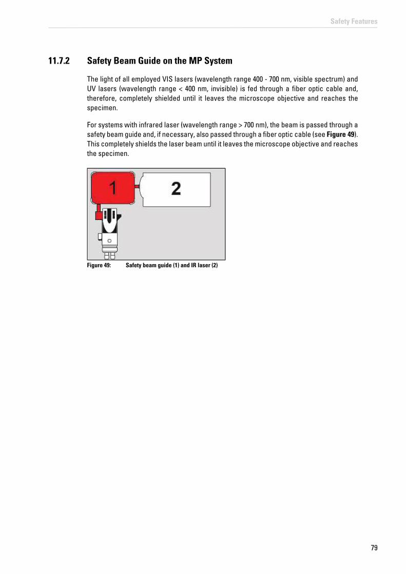
79
Safety Features
11.7.2 Safety Beam Guide on the MP System
The light of all employed VIS lasers (wavelength range 400 - 700 nm, visible spectrum) and UV lasers (wavelength range < 400 nm, invisible) is fed through a fiber optic cable and, therefore, completely shielded until it leaves the microscope objective and reaches the specimen.
For systems with infrared laser (wavelength range > 700 nm), the beam is passed through a safety beam guide and, if necessary, also passed through a fiber optic cable (see Figure 49). This completely shields the laser beam until it leaves the microscope objective and reaches the specimen.
Figure 49: Safety beam guide (1) and IR laser (2)

80
Safety Features

81
Safety Labels on the System
12 Safety Labels on the System
The corresponding safety labels depend on the laser configuration (VIS, UV, MP); they are attached in either English or German at the following locations.
WARNING Permanent eye and skin damage from failure to observe the safety labels on the system
Make sure that the safety labels shown in the User Manual are attached to the system.
Safety labels may not be removed.
Missing or damaged safety labels must be attached immediately and at the described location. Operation without the safety labels shown is not permitted. If you have any further questions, contact your laser safety officer or the Leica branch office in your country immediately.
12.1 Compact Supply Unit (Only for FLIM)
View of the compact supply unit:
Figure 50: Safety labels on the compact supply unit
Table 8: Safety Labels on the Compact Supply Unit (see Figure 50)
Position Safety label in English Translation of the safety label
1 DANGERLASER RADIATION CLASS 3BWHEN OPEN AVOID EXPOSURE TO BEAM
VORSICHTLASERSTRAHLUNG KLASSE 3BWENN ABDECKUNG GEÖFFNET NICHT DEM STRAHL AUSSETZEN

82
Safety Labels on the System
12.2 Flexible Supply Unit
Figure 51: Safety labels on the flexible supply unit
Table 9: Safety Labels on the Flexible Supply Unit (see Figure 51)
Position Safety label in English Translation of the safety label
1 DANGERLASER RADIATION CLASS 3BWHEN OPEN AVOID EXPOSURE TO BEAM
VORSICHTLASERSTRAHLUNG KLASSE 3BWENN ABDECKUNG GEÖFFNET NICHT DEM STRAHL AUSSETZEN

83
Safety Labels on the System
12.3 Inverted Microscope
Figure 52: Safety labels for the inverted microscope
Position System Safety label in English Translation of the safety label
1
VIS LASER RADIATION IS EMITTED FROM THIS APERTUREAVOID EXPOSURE
AUSTRITT VON LASERSTRAHLUNGBESTRAHLUNG VERMEIDEN
UV/MP VISIBLE AND INVISIBLE LASER RADIATION IS EMITTED FROM THIS APERTUREAVOID EXPOSURE
AUSTRITT VON SICHTBARER UND UNSICHTBARER LASERSTRAHLUNGBESTRAHLUNG VERMEIDEN
2
VIS DANGERLASER RADIATION CLASS 3BWHEN OPEN AVOID EXPOSURE TO BEAM
VORSICHTLASERSTRAHLUNG KLASSE 3BWENN ABDECKUNG GEÖFFNET NICHT DEM STRAHL AUSSETZEN
UV DANGERVISIBLE AND INVISIBLE LASER RADIATION CLASS 3BWHEN OPEN AVOID EXPOSURE TO BEAM
VORSICHTSICHTBARE UND UNSICHTBARE LASERSTRAHLUNG KLASSE 3BWENN ABDECKUNG GEÖFFNET NICHT DEM STRAHL AUSSETZEN
MP DANGERVISIBLE AND INVISIBLE LASER RADIATION CLASS 4WHEN OPEN AVOID EYE OR SKIN EXPOSURE TO DIRECT OR SCATTERED RADIATION
VORSICHTSICHTBARE UND UNSICHTBARE LASERSTRAHLUNG KLASSE 4WENN ABDECKUNG GEÖFFNET BESTRAHLUNG VON AUGE ODER HAUT DURCH DIREKTE ODER STREUSTRAHLUNG VERMEIDEN
Table 10: Safety labels for the inverted microscope (see Figure 52)
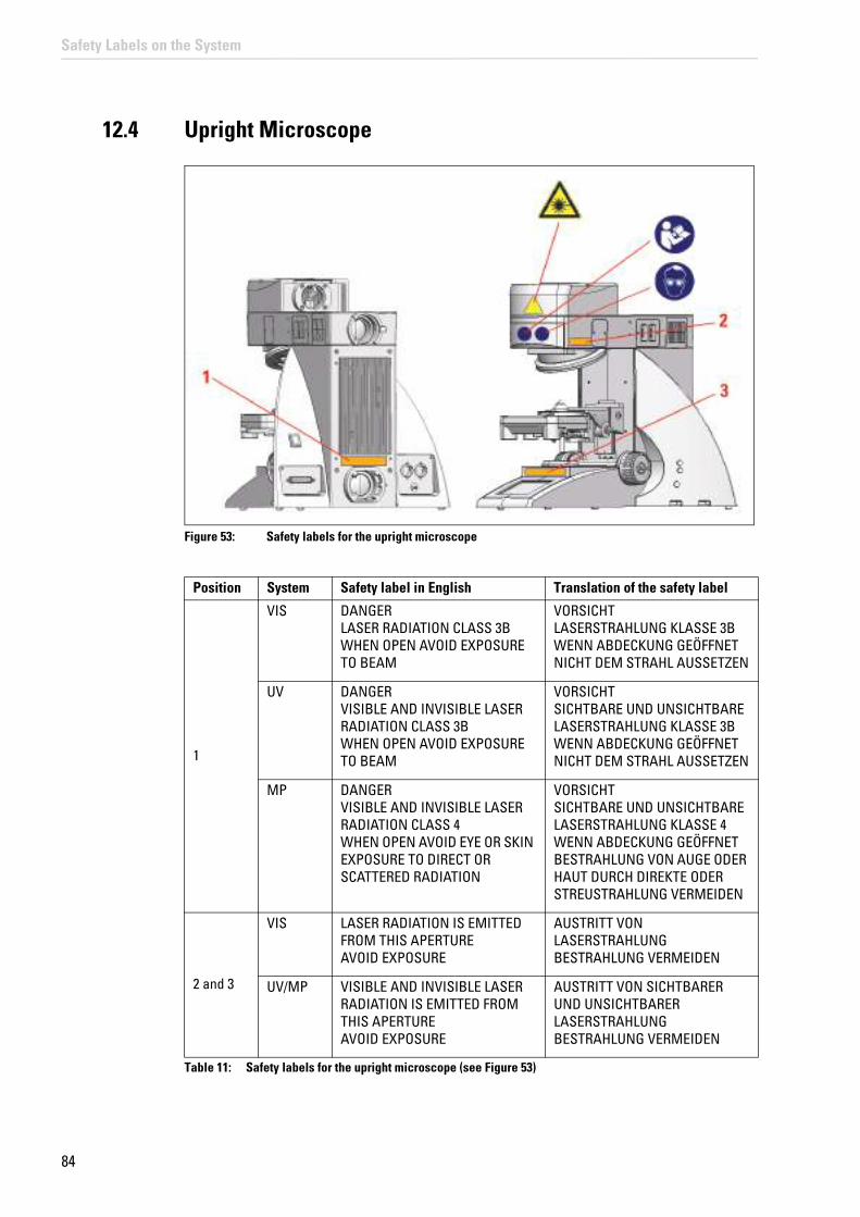
84
Safety Labels on the System
12.4 Upright Microscope
Figure 53: Safety labels for the upright microscope
Table 11: Safety labels for the upright microscope (see Figure 53)
Position System Safety label in English Translation of the safety label
1
VIS DANGERLASER RADIATION CLASS 3BWHEN OPEN AVOID EXPOSURE TO BEAM
VORSICHTLASERSTRAHLUNG KLASSE 3BWENN ABDECKUNG GEÖFFNET NICHT DEM STRAHL AUSSETZEN
UV DANGERVISIBLE AND INVISIBLE LASER RADIATION CLASS 3BWHEN OPEN AVOID EXPOSURE TO BEAM
VORSICHTSICHTBARE UND UNSICHTBARE LASERSTRAHLUNG KLASSE 3BWENN ABDECKUNG GEÖFFNET NICHT DEM STRAHL AUSSETZEN
MP DANGERVISIBLE AND INVISIBLE LASER RADIATION CLASS 4WHEN OPEN AVOID EYE OR SKIN EXPOSURE TO DIRECT OR SCATTERED RADIATION
VORSICHTSICHTBARE UND UNSICHTBARE LASERSTRAHLUNG KLASSE 4WENN ABDECKUNG GEÖFFNET BESTRAHLUNG VON AUGE ODER HAUT DURCH DIREKTE ODER STREUSTRAHLUNG VERMEIDEN
2 and 3
VIS LASER RADIATION IS EMITTED FROM THIS APERTUREAVOID EXPOSURE
AUSTRITT VON LASERSTRAHLUNGBESTRAHLUNG VERMEIDEN
UV/MP VISIBLE AND INVISIBLE LASER RADIATION IS EMITTED FROM THIS APERTUREAVOID EXPOSURE
AUSTRITT VON SICHTBARER UND UNSICHTBARER LASERSTRAHLUNGBESTRAHLUNG VERMEIDEN

85
Safety Labels on the System
12.5 Mirror Housing
Figure 54: Safety label on the mirror housing (top)
Table 12: Safety label on the mirror housing (see Figure 54)
Position System Safety label in English Translation of the safety label
1
VIS DANGERLASER RADIATION CLASS 3BWHEN OPEN AVOID EXPOSURE TO BEAM
VORSICHTLASERSTRAHLUNG KLASSE 3BWENN ABDECKUNG GEÖFFNET NICHT DEM STRAHL AUSSETZEN
UV DANGERVISIBLE AND INVISIBLE LASER RADIATION CLASS 3BWHEN OPEN AVOID EXPOSURE TO BEAM
VORSICHTSICHTBARE UND UNSICHTBARE LASERSTRAHLUNG KLASSE 3BWENN ABDECKUNG GEÖFFNET NICHT DEM STRAHL AUSSETZEN
MP DANGERVISIBLE AND INVISIBLE LASER RADIATION CLASS 4WHEN OPEN AVOID EYE OR SKIN EXPOSURE TO DIRECT OR SCATTERED RADIATION
VORSICHTSICHTBARE UND UNSICHTBARE LASERSTRAHLUNG KLASSE 4WENN ABDECKUNG GEÖFFNET BESTRAHLUNG VON AUGE ODER HAUT DURCH DIREKTE ODER STREUSTRAHLUNG VERMEIDEN

86
Safety Labels on the System
12.6 Cover for Replacement Flange
Front view of the cover:
Figure 55: Safety labels on the cover
Table 13: Safety Labels on the Cover (see Figure 55)
If the replacement flange for transmitted light is not equipped with a functional module, such as a lamp housing, a cover must be placed over the opening for laser safety reasons.
Position System Safety label in English Translation of the safety label
1
VIS DANGERLASER RADIATION CLASS 3BWHEN OPEN AVOID EXPOSURE TO BEAM
VORSICHTLASERSTRAHLUNG KLASSE 3BWENN ABDECKUNG GEÖFFNET NICHT DEM STRAHL AUSSETZEN
UV DANGERVISIBLE AND INVISIBLE LASER RADIATION CLASS 3BWHEN OPEN AVOID EXPOSURE TO BEAM
VORSICHTSICHTBARE UND UNSICHTBARE LASERSTRAHLUNG KLASSE 3BWENN ABDECKUNG GEÖFFNET NICHT DEM STRAHL AUSSETZEN
MP DANGERVISIBLE AND INVISIBLE LASER RADIATION CLASS 4WHEN OPEN AVOID EYE OR SKIN EXPOSURE TO DIRECT OR SCATTERED RADIATION
VORSICHTSICHTBARE UND UNSICHTBARE LASERSTRAHLUNG KLASSE 4WENN ABDECKUNG GEÖFFNET BESTRAHLUNG VON AUGE ODER HAUT DURCH DIREKTE ODER STREUSTRAHLUNG VERMEIDEN

87
Safety Labels on the System
12.7 Transmitted Light Detector (TLD)/Reflected Light Detector (RLD)
Position Safety label in English Translation of the safety label
1 DANGERVISIBLE AND INVISIBLE LASER RADIATION CLASS 4WHEN OPEN AVOID EYE OR SKIN EXPOSURE TO DIRECT OR SCATTERED RADIATION
VORSICHTSICHTBARE UND UNSICHTBARE LASERSTRAHLUNG KLASSE 4WENN ABDECKUNG GEÖFFNET BESTRAHLUNG VON AUGE ODER HAUT DURCH DIREKTE ODER STREUSTRAHLUNG VERMEIDEN
Figure 56: Safety labels on the transmitted light detector or reflection detector with MP systems
Table 14: Safety labels on the transmitted light detector or reflection detector (see Figure 56)
12.8 Scan Head
Figure 57: Safety labels on the scan head

88
Safety Labels on the System
Table 15: Safety labels on the scan head (see Figure 57)
Position System Safety label in English Translation of the safety label
1
VIS DANGERLASER RADIATION CLASS 3BWHEN OPEN AVOID EXPOSURE TO BEAM
VORSICHTLASERSTRAHLUNG KLASSE 3BWENN ABDECKUNG GEÖFFNET NICHT DEM STRAHL AUSSETZEN
UV DANGERVISIBLE AND INVISIBLE LASER RADIATION CLASS 3BWHEN OPEN AVOID EXPOSURE TO BEAM
VORSICHTSICHTBARE UND UNSICHTBARE LASERSTRAHLUNG KLASSE 3BWENN ABDECKUNG GEÖFFNET NICHT DEM STRAHL AUSSETZEN
MP DANGERVISIBLE AND INVISIBLE LASER RADIATION CLASS 4WHEN OPEN AVOID EYE OR SKIN EXPOSURE TO DIRECT OR SCATTERED RADIATION
VORSICHTSICHTBARE UND UNSICHTBARE LASERSTRAHLUNG KLASSE 4WENN ABDECKUNG GEÖFFNET BESTRAHLUNG VON AUGE ODER HAUT DURCH DIREKTE ODER STREUSTRAHLUNG VERMEIDEN
2
VIS LASER RADIATIONAVOID DIRECT EXPOSURE TO BEAM< 500mW 400-700nmCLASS 3B LASER PRODUCTIEC 60825-1: 2007
LASERSTRAHLUNGNICHT DEM STRAHL AUSSETZEN< 500mW 400-700nmLASER KLASSE 3BIEC 60825-1: 2007
UV LASER RADIATIONVISIBLE AND INVISIBLE - CLASS 3BAVOID DIRECT EXPOSURE TO BEAM< 500mW 350-700nmIEC 60825-1: 2007
LASERSTRAHLUNGSICHTBAR UND UNSICHTBAR - KLASSE 3BNICHT DEM STRAHL AUSSETZEN< 500mW 350-700nmIEC 60825-1: 2007
MP LASER RADIATIONVISIBLE AND INVISIBLE - CLASS 4AVOID EYE OR SKIN EXPOSURE TO DIRECT OR SCATTERED RADIATIONP< 4W 350-1600nm >80fsIEC 60825-1:2007
LASERSTRAHLUNGSICHTBAR UND UNSICHTBAR - KLASSE 4BESTRAHLUNG VON AUGE ODER HAUT DURCH DIREKTE ODER STREUSTRAHLUNG VERMEIDENP< 4W 350-1600nm >80fsIEC 60825-1:2007

89
Safety Labels on the System
12.9 White Light Laser
Rear side of white light laser:
Figure 58: Safety labels on the rear side of the white light laser
Table 16: Safety labels on the rear side of the white light laser (see Figure 58)
12.10 External UV Laser
Figure 59: Safety Label on External UV Laser 405
Position Safety label in English Translation of the safety label
1 DANGERLASER RADIATION CLASS 3BWHEN OPEN AVOID EXPOSURE TO BEAM
VORSICHTLASERSTRAHLUNG KLASSE 3BWENN ABDECKUNG GEÖFFNET NICHT DEM STRAHL AUSSETZEN
2 LASER RADIATIONAVOID DIRECT EXPOSURE TO BEAM< 500mW 400-700nmCLASS 3B LASER PRODUCTIEC 60825-1: 2007
LASERSTRAHLUNGNICHT DEM STRAHL AUSSETZEN< 500mW 400-700nmLASER KLASSE 3BIEC 60825-1: 2007
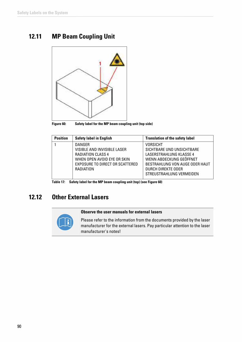
90
Safety Labels on the System
12.11 MP Beam Coupling Unit
Figure 60: Safety label for the MP beam coupling unit (top side)
Table 17: Safety label for the MP beam coupling unit (top) (see Figure 60)
12.12 Other External Lasers
Observe the user manuals for external lasers
Please refer to the information from the documents provided by the laser manufacturer for the external lasers. Pay particular attention to the laser manufacturer's notes!
Position Safety label in English Translation of the safety label
1 DANGERVISIBLE AND INVISIBLE LASER RADIATION CLASS 4WHEN OPEN AVOID EYE OR SKIN EXPOSURE TO DIRECT OR SCATTERED RADIATION
VORSICHTSICHTBARE UND UNSICHTBARE LASERSTRAHLUNG KLASSE 4WENN ABDECKUNG GEÖFFNET BESTRAHLUNG VON AUGE ODER HAUT DURCH DIREKTE ODER STREUSTRAHLUNG VERMEIDEN

91
Switching On the System
13 Switching On the System
The TCS SP8 SMD is available in different versions. You must precisely follow the switch-on sequence that applies to your system variant. During FLIM experiments, it is also possible to operate the system with a compact supply unit.
13.1 Confocal System with Flexible Supply Unit
NOTICE Damage is possible when contacting the specimen stage
When using an inverted microscope, the illuminator arm must be swung back before the system start and LAS AF start because the stage can damage the condenser, the objective or the specimen during initialization.
1. If you are using a fluorescence lamp EL6000, switch it on first.
Figure 61: EL6000
2. If you are using a HyD RLD, switch it on at its supply unit (see Figure 80). You can find additional information on the HyD RLD in Chapter 13.3.
3. Switch on the workstation and the microscope on the main switch board of the flexible supply unit (see Figure 62, item 1). You do not have to start the operating system—it starts automatically when you switch on the workstation. Wait until the startup process has concluded.
NOTICE Objective damage is possible when contacting the specimen stage
When using an upright microscope, the specimen stage must be moved down before the system start and LAS AF start because it could come into contact with the objective during initialization and damage the objective.

92
Switching On the System
Figure 62: Overview of the main switch board on the flexible supply unit
4. Switch off the multiple socket outlet on the trolley. Switch on the SMD workstation if it does not start up automatically.
5. Check whether the microscope is switched on. The microscope is operational once the readiness indicator (Figure 63, item 1) on the toggle switch is lit up. If the readiness indicator is not lit, activate the electronics box toggle switch (Figure 63, item 2).
Figure 63: Microscope electronics box
6. If your system has an infrared laser (MP) or an optical parametric oscillator (OPO), switch on the NDD detection unit.
Figure 64: Switch on the NDD detection unit
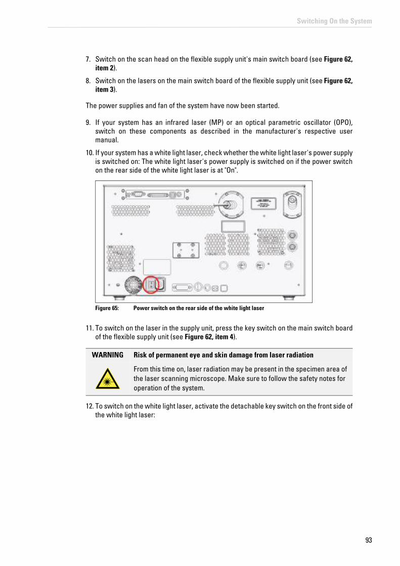
93
Switching On the System
7. Switch on the scan head on the flexible supply unit's main switch board (see Figure 62, item 2).
8. Switch on the lasers on the main switch board of the flexible supply unit (see Figure 62, item 3).
The power supplies and fan of the system have now been started.
9. If your system has an infrared laser (MP) or an optical parametric oscillator (OPO), switch on these components as described in the manufacturer's respective user manual.
10. If your system has a white light laser, check whether the white light laser's power supply is switched on: The white light laser's power supply is switched on if the power switch on the rear side of the white light laser is at "On".
Figure 65: Power switch on the rear side of the white light laser
11. To switch on the laser in the supply unit, press the key switch on the main switch board of the flexible supply unit (see Figure 62, item 4).
WARNING Risk of permanent eye and skin damage from laser radiation
From this time on, laser radiation may be present in the specimen area of the laser scanning microscope. Make sure to follow the safety notes for operation of the system.
12. To switch on the white light laser, activate the detachable key switch on the front side of the white light laser:

94
Switching On the System
Figure 66: Key Switch for the White Light Laser
13. If you are using an external 355 and 405 (inclusive) UV laser, make sure that the power switch is in the "On" position (not possible for FLIM, FCS and FLCS images).
Figure 67: Power switch on external UV laser 355
Figure 68: Power switch on external UV laser 405
14. Press the following key switches to switch on the external UV laser 355 including 405:
White Light Laser Error Messages
An error report appears in the display of the white light laser.
• if the room temperature exceeds 40°C -> the white light laser switches itself off and can only be turned back on after the room cools off.
• In case of mechanical shock or vibrations -> switch off the white light laser and turn it back on after 10 seconds.

95
Switching On the System
Figure 69: Key switch on the power supply of external UV laser 355
Figure 70: Key switch on external UV laser 405
15. After the workstation has started, log on to the operating system.
Change password
After logging on with your own user ID, you may change your password. To do so, press the Ctrl, Alt and Del keys at the same time.Then, click Change password. The Change password dialog box opens.
Now you can start the LAS AF software.
Using a personalized user ID
Use your personal user ID if one has been set up. This ensures that user-specific settings are saved and maintained for this user only. If the system administrator has not yet assigned a personal user ID, log on as "TCS_User". The default password is "True!Confocal55".

96
Switching On the System
13.2 Confocal System with Compact Supply Unit (Only with FLIM)
1. If you are using a fluorescence lamp EL6000, switch it on first.
Figure 71: EL6000
2. If you are using a HyD RLD, switch it on at its supply unit. You can find additional information on the HyD RLD in Chapter 13.3.
Figure 72: HyD RLD supply unit
3. Switch on the workstation. The operating system starts automatically. Wait until the startup process has concluded.
4. Switch off the multiple socket outlet on the trolley. Switch on the SMD workstation if it does not start up automatically.
5. Turn on the microscope by actuating the electronics box toggle switch (Figure 73, item 2). The microscope is operational once the readiness indicator (Figure 73, item 1) on the toggle switch is lit up.

97
Switching On the System
Figure 73: Microscope electronics box
6. If your system has an infrared laser (MP) or an optical parametric oscillator (OPO), switch on the NDD detection unit:
Figure 74: Switch on the NDD detection unit
7. Switch on the scan head on the front side of the compact supply unit (see Figure 75, item 1).
Figure 75: Overview of the Control Panel Field on the Compact Supply Unit
8. Switch on the lasers on the front side of the compact supply unit (see Figure 75, item 2).
The system's power supplies and fans are started.
9. If your system has an infrared laser (MP) or an optical parametric oscillator (OPO), switch on these components as described in the manufacturer's respective user manual.

98
Switching On the System
10. To switch on the laser in the supply unit, press the key switch on the front side of the compact supply unit (see Figure 75, item 3).
WARNING Risk of permanent eye and skin damage from laser radiation
From this time on, laser radiation may be present in the specimen area of the laser scanning microscope. Make sure to follow the safety notes for operation of the system.
11. If you are using an external 355 and 405 (inclusive) UV laser, make sure that the power switch is in the "On" position (not possible for FLIM, FCS and FLCS images).
Figure 76: Power switch on external UV laser 355
Figure 77: Power switch on external UV laser 405
12. Press the following key switches to switch on the external UV laser 355 including 405:
Figure 78: Key switch on the power supply of external UV laser 355

99
Switching On the System
Figure 79: Key switch on external UV laser 405
13. After the workstation has started, log on to the operating system.
Using a personalized user ID
Use your personal user ID if one has been set up. This ensures that user-specific settings are saved and maintained for this user only. If the system administrator has not yet assigned a personal user ID, log on as "TCS_User". The default password is "True!Confocal55".
Change password
After logging on with your own user ID, you may change your password. To do so, press the Ctrl, Alt and Del keys at the same time.Then, click Change password. The Change password dialog box opens.
Now you can start the LAS AF software.
13.3 HyD Reflected Light Detectors (HyD RLDs)
• Never change or remove the filter cube or short pass filter during operation.
• The filter cube cover (see Figure 81, item 1) ensures the housing's EMC stability and prevents light from entering or exiting.
• Replacement of the short pass filter is only allowed starting from LAS AF Version 2.7 or later.
If you are using HyD RLDs, you have to switch them on before LAS AF starts. Otherwise, the LAS AF software cannot initialize the detectors. The HyD RLDs consist of a supply unit (see Figure 80) and a detector module (see Figure 81).
The power switch for switching on and off the power supply and the cooling for the detector module is located on the front side of the supply unit (see Figure 80).
For image acquisition, activate the detectors in LAS AF. The yellow status LED (see Figure 81, item 2) flashes if photons are being detected.
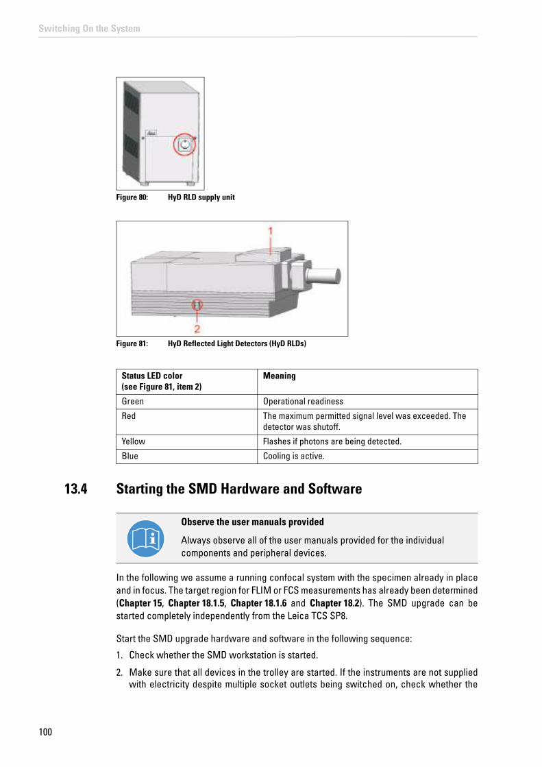
100
Switching On the System
Figure 80: HyD RLD supply unit
Figure 81: HyD Reflected Light Detectors (HyD RLDs)
13.4 Starting the SMD Hardware and Software
In the following we assume a running confocal system with the specimen already in place and in focus. The target region for FLIM or FCS measurements has already been determined (Chapter 15, Chapter 18.1.5, Chapter 18.1.6 and Chapter 18.2). The SMD upgrade can be started completely independently from the Leica TCS SP8.
Start the SMD upgrade hardware and software in the following sequence:
1. Check whether the SMD workstation is started.
2. Make sure that all devices in the trolley are started. If the instruments are not supplied with electricity despite multiple socket outlets being switched on, check whether the
Status LED color(see Figure 81, item 2)
Meaning
Green Operational readiness
Red The maximum permitted signal level was exceeded. The detector was shutoff.
Yellow Flashes if photons are being detected.
Blue Cooling is active.
Observe the user manuals provided
Always observe all of the user manuals provided for the individual components and peripheral devices.

101
Switching On the System
power switch is in the "ON" position.
3. Start the laser driver and switch the laser on. If you are using the PDL 828 Sepia II laser driver, set the key switch to the "ON" position. Prior to data acquisition, the laser head should be operated for a few minutes to stabilize. If you use a PDL 828 Sepia II, start the specific Sepia software on the SMD workstation and set the laser settings there (refer to corresponding manuals).
4. Start the SymPhoTime software on the SMD workstation.
5. Open an existing workspace by selecting Load Workspace in the File menu or create a new workspace by selecting New Workspace in the File menu (see SymPhoTime manual).
6. Set the correct fluorescence filter on the corresponding filter holder position of the external PicoQuant detector unit or on the Leica TCS SP8. Select the correct SMD filter cube in the X1 port adapter (Chapter 23, Figure 188). If you have a dual-channel APD detector unit, set the variable beam splitter unit to the correct position (see dual channel detector unit manual for details).
7. Be sure that no light falls on the detectors. Either switch on the power supply or, if using a DSN 102 power supply, start the respective detector by selecting the corresponding channel button on the DSN 102.
The SMD upgrade is now ready to use. The communication between the SP8 confocal system itself and the SMD upgrade electronics starts at the beginning of the data acquisition.

102
Switching On the System
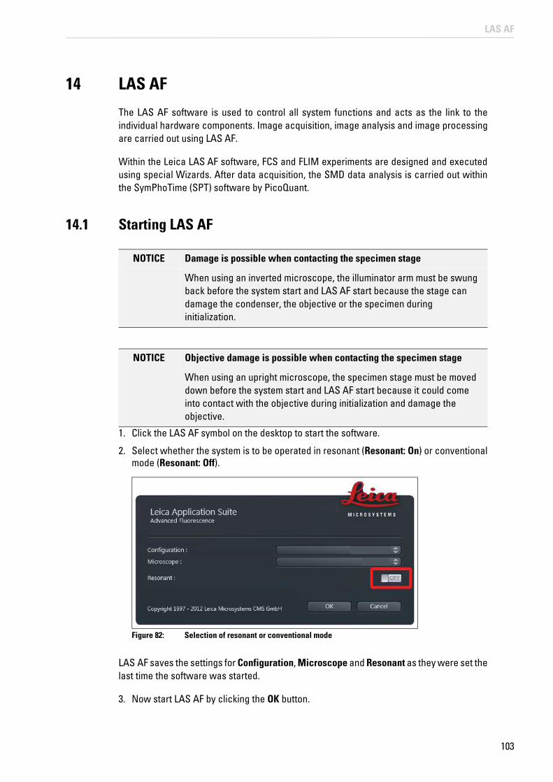
103
LAS AF
14 LAS AF
The LAS AF software is used to control all system functions and acts as the link to the individual hardware components. Image acquisition, image analysis and image processing are carried out using LAS AF.
Within the Leica LAS AF software, FCS and FLIM experiments are designed and executed using special Wizards. After data acquisition, the SMD data analysis is carried out within the SymPhoTime (SPT) software by PicoQuant.
14.1 Starting LAS AF
NOTICE Damage is possible when contacting the specimen stage
When using an inverted microscope, the illuminator arm must be swung back before the system start and LAS AF start because the stage can damage the condenser, the objective or the specimen during initialization.
1. Click the LAS AF symbol on the desktop to start the software.
2. Select whether the system is to be operated in resonant (Resonant: On) or conventional mode (Resonant: Off).
Figure 82: Selection of resonant or conventional mode
LAS AF saves the settings for Configuration, Microscope and Resonant as they were set the last time the software was started.
3. Now start LAS AF by clicking the OK button.
NOTICE Objective damage is possible when contacting the specimen stage
When using an upright microscope, the specimen stage must be moved down before the system start and LAS AF start because it could come into contact with the objective during initialization and damage the objective.

104
LAS AF
You are now in the main LAS AF view.
14.2 Structure of the Graphical User Interface
Figure 83: Structure of the Graphical User Interface
Scaling range: Using the slider, you can modify the (size) display of the user interface. On the right next to the slider, there is a reset button which you can use to reset the scaling to the default setting.
Operating mode selection: Here you can set the operating mode you would like to use for image acquisition and analysis independently of your system configuration.
Steps: Various steps are available depending on the selected operating mode. The TCS SP8 base module has the following four steps: Configuration, Acquire, Process, Quantify.
Menu: The File and Help dropdown menus are located here.
Tab area:
1 Scaling range 7 Image display
2 Operating mode selection 7a Image display settings
3 Steps 7b Image processing and image analysis options
4 Menu 7c Channel display
5 Tab area 8 Image acquisition buttons
6 Working area

105
LAS AF
The displayed tabs depend on the selected step. In the TCS SP8's basic operating mode, the following tabs are assigned to the steps:
• Acquire step: Experiments tab: Directory tree for opened files Acquisition tab: Hardware settings for the current experiment and parameter settings for image acquisition
• Process step: Experiments tab: Directory tree for opened files Process Tools tab: Overview of the functions available in this step
• Quantify step: Experiments tab: Directory tree for opened files Tools tab: Overview of the functions available in this step
Working area: Depending on the step and tab selected, different dialogs are available in the working area:
• Acquire step: Beam Path Settings: In this dialog, the beam path is shown schematically. You can select and adjust the lasers and the system components along the beam path and the detectors for image acquisition.
• Process step: Appropriate processing options and a preview image appear in the working area based on which function you have selected in the Process Tools tab.
• Quantify step: The working area is divided into two tabs: Graphs: Graphic representation of values that were measured in the entire image or in regions of interest (ROI) Statistics: Display of statistical values that were determined in the entire image or in plotted regions of interest (ROI)
Image display: Acquired images can be displayed and regions of interest (ROI) and additional information can be plotted here.
Image display settings: This area contains buttons used to change the display options for acquired images (such as color).
Image processing and image analysis options: This area contains buttons that can be used to add information to the image, such as text, arrows or dimensions. In addition, there is a button that enables regions of interest (ROI) to be plotted in the image display.
Channel display: Here, you can select how the acquired image is to be displayed. If you have excited your specimen with multiple laser lines, you can use the buttons to select whether the different channels are displayed individually, next to each other or in one image.
Image acquisition buttons: These buttons are available to you during the Acquire and Quantify steps. Here you can

106
LAS AF
select how the acquisition is to be started:
• Autofocus: Focusing using the selected settings
• Live: Acquisition of a live image
• Capture Image: Acquisition of an individual image
• Start: Series of acquisitions using the selected settings
The software's "experiment concept" allows logically interconnected data to be managed together. The Experiments tab is displayed in a tree structure in different steps. Experiments are managed there:
Figure 84: View of the Experiments tab
Experiments have an export function for opening images and animations in an external application. The following selection of export formats is available if you select an experiment by right-clicking it:
Figure 85: Possible export formats

107
LAS AF
14.3 Design of the FLIM Wizard in LAS AF
The LAS AF software includes a FLIM wizard with operating steps for capturing and optimizing image data as well as a function that enables FLIM measurements to be carried out.
To start the FLIM Wizard, open the operating mode selector and select FLIM (Figure 86).
Figure 86: Starting the SMD FLIM Wizard in LAS AF
When the Wizard is opened, the settings for the beam path configured are transferred to the Wizard. They can be further modified within the Wizard.
The basic structure of the FLIM Wizard corresponds to the structure of the LAS AF user interface (see Figure 83). Special features of the Wizard are represented on the following pages.
The Wizard is organized into five steps:
• Overview workstep: Here, you can get an overview of the steps additionally contained in the Wizard.

108
LAS AF
Figure 87: Overview of the FLIM Wizard steps
• "Setup Corr-ring" step Some immersion objectives have a correction ring to optimally correct for differences in the refractive index between immersion and specimen and temperature effects. An optimum adjustment of the correction ring correlates with the best possible optical resolution of the system. In the Setup Corr-ring step, the beam path is preconfigured for a fast and efficient adjustment of the correction ring.
• Setup Imaging workstep: Here, you can establish and optimize the conditions for the acquisition of a reference image. In the Setup Imaging step, the FLIM data acquisition cannot be started.
• Step Setup FLIM: Here, you can define and optimize instrument parameters for the FLIM measurement. The FLIM measurement instrument parameters (such as selection of the laser line and intensity, image size, pinhole size, etc.) are managed independently of the parameters for image acquisition in the Setup Imaging step. The optimal laser intensity can be determined with a FLIM test measurement (selecting the FLIM Test button).
• Step Measurements: Here, you can define the FLIM experiment (exposure time of the individual FLIM images, definition of FLIM volume stacks, FLIM time series or, for internal SP FLIM, FLIM lambda stacks).

109
LAS AF
In each step, two to three different tabs are shown in the tab area:
• On the Experiments tab, the intensity image data shown on the image display (LAS AF Viewer) is saved. The FLIM data is only saved in the PicoQuant software SymPhoTime.
• On the Acquisition tab, you configure the settings for image acquisition such as scan speed, zoom, or pinhole diameter or you can define a stack or time series for FLIM measurements.
• On the Setup tab, you can select external or internal detectors for FLIM, run FLIM test measurements, and edit file names and comments.
After completing the FLIM measurements, you can close the Wizard by selecting the TCS SP8 operating mode (Figure 88).
Figure 88: Closing the Wizard

110
LAS AF
14.4 Design of the FCS Wizard in LAS AF
The LAS AF software includes an FCS Wizard with steps for capturing and optimizing image data as well as a function that enables FCS measurements to be carried out on previously defined points.
To start the FCS Wizard, open the operating mode selector and select FCS(Figure 89). The system must not be in resonant mode. If it is, you must restart the software. While doing so, disable the "Resonant Scanner" check box after starting LAS AF.
Figure 89: Starting the FCS Wizard in LAS AF
When the Wizard is opened, the settings for the beam path already configured are transferred to the Wizard. They can be further modified within the Wizard.
The basic structure of the FCS Wizard corresponds to the structure of the LAS AF user interface (see Figure 83). Special features of the Wizard are represented on the following pages.
The Wizard is organized into five steps:
• Overview workstep: Here, you can get an overview of the different steps within the Wizard (Figure 90).

111
LAS AF
Figure 90: Overview of the SMD FCS Wizard steps
• "Setup Corr-ring" step The recommended FCS objective (63x Plan Apo 1.2 W) has a correction ring to optimally correct for differences in the refractive index between immersion and specimen and temperature effects. An optimum adjustment of the correction ring correlates with the best possible optical resolution of the system – a basic requirement for FCS measurements. In the Setup Corr-ring step, the beam path is preconfigured for a fast and efficient adjustment of the correction ring.
• Setup Imaging workstep: Here, you can establish and optimize the parameters for scan acquisition. This step also includes a semi-automated routine for fine-tuning the park position of the scanner (Chapter 18.1.2).
• Setup FCS step: Here, you can define and optimize instrument parameters for the FCS measurement. The FCS measurement instrument parameters (such as selection of the laser line and intensity, pinhole size, etc.) are managed independently of the parameters for image acquisition. The FCS settings can also be saved and edited. To optimize the measurement conditions, you can use the crosshair to define an FCS measurement point in the previously acquired xy or xz image or an xyz or xzy stack, and carry out a test measurement there.

112
LAS AF
• Step Measurements: Here, you can define multiple FCS measuring points in the previously acquired xy or xz image or xyz or xzy stack, then carry out consecutive and automatic FCS measurements defined in the Setup FCS step. The list of measuring points can be saved and reloaded.
In each step, different tabs are shown in the tab area:
• On the "Workflow" tab you will find a suggested workflow and the functions associated with it.
• On the "Experiments" tab, the image data are stored.
• On the Acquisition tab, you can configure the settings for image acquisition, such as scan speed, zoom or pinhole diameter, or you can define a series of FCS measurements.
In all steps of the Wizard, you can access continuous scanning or acquire a single image or z or y-stack at any time with "Live", Capture image and Start. The conditions for image acquisition that you defined in Setup Imaging are used for this.
Then, if you carry out the FCS measurement in step Setup FCS and do not move the crosshair, the scanner is simply parked in the center of the image.
After the completion of the FCS measurements, you can close the Wizard by selecting the operating mode TCS SP8 (Figure 91).
Figure 91: Closing the Wizard
FCS Measurements in Solutions
Even when carrying out FCS measurements in solutions, you have to acquire an xy image before the first FCS measurement. This is necessary so that the scanner can become oriented in the scan field. The information content of this image is not relevant here.

113
LAS AF
14.5 LAS AF Online Help
14.5.1 Structure of Online Help
Online Help is divided into seven main chapters:
• General Information: Contains legal notices and general information on LAS AF.
• About LAS AF Online Help: Contains general information for the LAS AF Online Help.
• LAS AF Steps: Contains detailed dialog descriptions for the user interface in LAS AF steps.
• LAS AF Application Wizards: Contains detailed dialog descriptions for the user interface in LAS AF application wizards and extensive documentation for the MatrixScreener wizard.
• LAS AF Advanced Time Lapse Modes: Contains detailed dialog descriptions for the user interface in live data mode and in ElectroPhysiology operating mode.
• LAS AF Express View: Contains a detailed description of the LAS AF express view file browser.
• Additional Information: Contains background information on topics related to LAS AF, applications and systems, such as digital image processing, dye separation and objective accessories.
14.5.2 Accessing Online Help
In the menu bar, click on the Help menu. The menu drops down and reveals search-related options, including the following:
Figure 92: Online help menu
• Contents: Opens the table of contents for Online Help.
• Index: Opens the index for Online Help.
• Search: Opens the full-text search function for Online Help.
• About: Calls up the User Configuration dialog.
14.5.3 Selecting the Language for Online Help
By default, English is set as the language for Online Help. In order to select another language, follow these steps:

114
LAS AF
1. In LAS AF, switch to the Configuration step.
2. Click on the User Config button on the left side to access the User Configuration dialog.
3. In the User Configuration dialog, select the desired language under Help Language.
Figure 93: Selecting the language for Online Help
The next time you call up Online Help, the help topics will be displayed in the selected language.
The Help menu provides a second option for changing the language. Call up the Help -> About menu. The User Configuration dialog opens and you can select the desired language (see Figure 93).
14.5.4 Using Online Help
A navigation window is on the left side of the screen in the LAS AF Online Help. It contains three tabs that allow the contents of Online Help to be retrieved in different ways.
• Contents tab: Contains the table of contents in the form of a directory tree that can be expanded or collapsed. Double-click an entry in the table of contents to display the corresponding information.
• Index tab: Displays all keywords alphabetically and hierarchically. Double-click on an index entry to display the corresponding information or press the Display button. You can also search by keyword: Enter the word you would like to search for in the search box. Online help displays the keyword that is the closest match to the specified word.
• Search tab: Allows full-text searching. Enter the word you would like to search for in the search box. Click on the List Topics button. An alphabetically structured list of topics containing the keyword is displayed.

115
LAS AF
14.5.5 Full-text Search with Logically Connected Search Terms
In Online Help, you can use the full-text search function to search for words and for phrases enclosed in quotation marks. You can also use placeholders when searching (such as * or ?).
You can run a full-text search using logical operators (such as boolean operators) in order to link search terms and thereby increase the accuracy of search results. In the input field on Online Help's Search tab, directly input the desired logical operator together with the search terms. The following logical operators are available:
• Excitation AND Wavelength: Finds help topics that contain both the word "excitation" and the word "wavelength".
• Excitation OR Wavelength: Finds help topics that contain either the word "excitation" or the word "wavelength" or both.
• Excitation NEAR Wavelength: Finds help topics where the word "excitation" and the word "wavelength" are located within a specific search radius. This method also looks for words that are similar in spelling to the words specified in the phrase.
• Excitation NOT Wavelength: Finds help topics that contain the word "excitation" and not the word "wavelength".

116
LAS AF

117
Selecting the Laser
15 Selecting the Laser
15.1 Activate laser as the excitation source in the configuration menu
All available lasers can be used for images of normal image intensity.
The lasers are switched on outside the Wizards in the TCS SP8 operating mode.
1. To activate a certain laser, select the Configuration step in the TCS SP8 LAS AF operating mode.→
2. Select the Laser Config button (Figure 94) and enable the desired laser with the allocated check box (Figure 96).
Figure 94: LAS AF configuration window
3. You can also query the laser configuration window from a single Wizard. Click on the +button in the laser dialog in the Beam Path Settings (Figure 95). The corresponding laser configuration window (Figure 96) opens.
Figure 95: Button to open a laser configuration window

118
Selecting the Laser
Figure 96: Activate laser in the LAS AF laser configuration window
15.1.1 Using Continuous Wave VIS Lasers
1. Open the laser shutter in Beam Path Settings (Figure 97, item 1).
2. Set the desired laser line intensity using the slider (Figure 97, item 2).
Open shutter
The red-colored ON button (Figure 97, item 1) signals that the shutter is open.
Figure 97: Activating the continuous wave VIS laser in LAS AF
3. On AOBS systems, make sure the acousto-optical beam splitter is in fluorescence mode. Now select the AOBS button to do this (Figure 98, item 2).

119
Selecting the Laser
Figure 98: Beam Path Settings: MFP setting (1) and selection of AOBS (2)
4. With beam splitter systems, set the beam splitter to one which corresponds to the continuous wave laser line selected for the scan head.
5. If the system has a multifunction port (MFP), it should be set to Substrate (Figure 98, item 1.
15.1.2 Using MP lasers
1. During MP excitation, open the MP laser shutter in Beam Path Settings (Figure 99, item 1) and click on the button to open the MP Laser Configuration dialog (Figure 99, item 2).
Figure 99: Activating the MP Laser in LAS AF
Use this dialog to open and close the shutter and set the laser wavelength (Figure 102, item 3). Mode shows the current status of the laser (Figure 101, item 2).
2. Before using the MP laser, you must open a second shutter on the laser housing(Figure 100 ) in the MP Laser Configuration dialog (Figure 101, item 1). Click on the MP Shutter button and hold the mouse button at least two seconds. The selection indicator for the button will turn red (Figure 102).
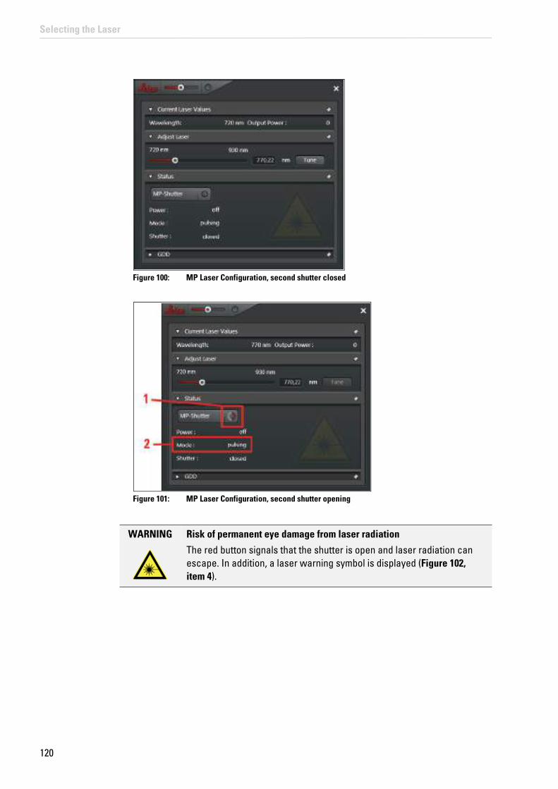
120
Selecting the Laser
Figure 100: MP Laser Configuration, second shutter closed
Figure 101: MP Laser Configuration, second shutter opening
WARNING Risk of permanent eye damage from laser radiation
The red button signals that the shutter is open and laser radiation can escape. In addition, a laser warning symbol is displayed (Figure 102, item 4).

121
Selecting the Laser
Figure 102: MP Laser Configuration, second shutter open
3. You can now set the wavelength of the MP laser. Use either the slider (Figure 102, item 3) or enter the desired wavelength directly.
4. Select a suitable neutral filter strength for the light incidence (Trans) and/or define the Gain and Offset from the EOM (Figure 99, item 3).
5. The position of the multifunction port (MFP) should be set to SP680 or SP700.
6. For beam splitter systems, set the beam splitter to substrate (Figure 103).
Figure 103: Setting the beam splitter to substrate
15.1.3 Using Pulsed VIS Lasers
1. Switch on the laser driver (PDL 800, SEPIA) as instructed in the corresponding manual.
2. Select External as the trigger on the front of the laser driver or, when using a SEPIA II, in the corresponding driver software.
3. Set the intensity to a value between 3.5 and 9 (on the lever on the front side of the PDL driver) or between 35 % and 90 % (in the SEPIA II software driver).

Notes about laser intensity
For intensities under 3.5 (PDL) or 35 % (SEPIA II), the pulsed output of the laser light can be interrupted. Do not select too high of values on the laser driver (PDL or SEPIA) unless the laser intensity is not sufficient. High values increase the laser pulse length.
122
Selecting the Laser
4. Adjust the laser intensity on the laser driver in order to obtain the shortest laser pulse length (see Chapter 17.12 with respect to measuring instrument response time – "IRF"). In a second step, adjust the laser intensity on the laser or the laser coupling module (LCU) (Chapter 9.6), to carry out a corresponding adjustment with respect to the correct fluorescence count rate for FLIM detection.
5. Close the shutter of the continuous wave VIS laser in Beam Path Settings and move all AOTF sliders to the 0 position.
6. Open the shutter for pulsed lasers by turning the button to ON (Figure 104, item 1).
7. Activate the desired laser by moving the corresponding slider up all the way (Figure 104, item 2).
In the control field of the pulsed lasers, the slider setting does not affect the laser intensity. The laser intensity is controlled outside the LAS AF on the laser driver (PDL800, SEPIA) and on the laser coupling module.
8. Make sure that the multifunction port (MFP, Figure 104, item 3) is in the right position (Table 18).
Figure 104: Settings for pulsed VIS lasers in Beam Path Settings
Observe the user manuals provided
Always observe all of the user manuals provided for the individual components and peripheral devices.

123
Selecting the Laser
Table 18: MFP settings based on the excitation wavelength used
You can use pulsed VIS lasers together with a pulsed UV laser. The MFP setting is not influenced by UV. It is defined by the selection of the pulsed VIS lasers.
9. If you work on a beam splitter system, set the beam splitter to Substrate in the Beam Path Settings in LAS AF (Figure 105). In case you want to use a pulsed laser combined with a continuous wave laser line, chose the corresponding main beam splitter that reflects the continuous wave laser line into the scan head.
Figure 105: Setting the beam splitter to substrate
Configuration Lasers used MFP settings in LAS AF
405 405 Substrate
405+440 405440
SubstrateRSP 445
405+470 405405+470470
SubstrateSD 470SD 470
405+470+640 405405+470405+640470470+640640
SubstrateDD 470+640DD 470+640DD 470+640DD 470+640DD 470+640
440 440 RSP 445
440+470 440470
RSP 445SD 470
470 470 RSP 445
470+640 470470+640640
DD 470+640DD 470+640DD 470+640
Combination pulsed and continuous wave VIS excitation
Do not use any pulsed VIS excitation together with continuous wave VIS excitation for continuous wave laser lines close to the wavelengths of the pulsed laser (such as the combination 470 nm pulsed + 488 nm continuous wave), as no optimum MFP setting exists for such a combination.

124
Selecting the Laser
15.1.4 Using Pulsed UV Lasers
1. Open the shutter for pulsed lasers.
2. Activate the 405 nm laser by moving the corresponding slider upwards (Figure 106, item 1).
Figure 106: Settings for the UV lasers in Beam Path Settings
3. If no other pulsed laser is used, you can set the multifunction port (MFP) to Substrate(Figure 106, item 2.
4. Follow the settings from Table 18 if you are using additional pulsed lasers at the same time.
15.1.5 Using a Pulsed White Light Laser
1. In the laser dialog in the Beam Path Settings, you can switch between the laser spectra for conventional laser lines or the white light laser. In order to call up the laser spectrum of the white light laser, click the Switch to Whitelight button (Figure 107).
Figure 107: Calling up the white light laser laser spectrum
2. Switch the white light laser to ON (Figure 108, item 1). The red-colored ON button signals that the shutter is open. Then, a laser line appears in the laser spectrum.

125
Selecting the Laser
3. You can activate up to eight laser lines simultaneously. Click the corresponding buttons (Figure 108, item 2). The position of the laser lines in the spectrum can be moved as desired.
4. Adjust the power of the line by adjusting the slider for the respective laser line.
5. Select Constant Power mode for excitation scans using the white light laser. This sets the laser power automatically to 100 %. When Constant Percentage (Figure 108, item 3) is selected, work can be done using less power (e.g. 70 %).
Figure 108: Adjusting Constant Percentage
6. Then, click on the nearby button (Figure 108, item 4) to call up the laser configuration window.
7. In the Currently available Lasers dialog, you can set the laser power (Figure 109). To do this, enable the laser (Figure 109, item 1). Set the desired laser power using the slider (Figure 109, item 2).
o
Figure 109: Settings in the Settings menu

126
Selecting the Laser
Automatic MFP positioning
Within the FLIM Wizard, the MFP positioning is done automatically. MFP positioning occurs at the corresponding beam splitters whenever a laser selection is changed. Outside of the wizard, the user must configure this setting on his or her own.
Settings made automatically can be modified later by the user. These user-defined settings can be saved and reloaded later.
Continuous wave mode (cw mode)
Depending on the configuration, the mode of the pulsed 405 nm laser can be changed to continuous wave mode on the PDL800D or SEPIA II driver (see corresponding manuals). In continuous wave mode, no beam blanking of the laser is active. This means that creating a special region of interest (ROI) and line-by-line sequential scanning do not work!

127
FLIM Data Acquisition
16 FLIM Data Acquisition
You can acquire a FLIM image using a pulsed laser, an internal or external FLIM detector, and an external PicoQuant TCSPC unit.
16.1 Setup Imaging Step – Image Acquisition
1. Start the FLIM Wizard in LAS AF. To do so, open the operating mode selector and select FLIM (Figure 110).
Figure 110: Selecting FLIM Wizard
2. Open the Setup Imaging step.
The scan mode xt and sequential scan are not supported. Except for this, the image acquisition procedure is the same as the general procedure outside the FLIM Wizard.
16.1.1 Selecting Detectors for the Image Acquisition
You can use PMTs or APDs for image acquisition. PMTs are distinguished by having wide dynamic range; APDs are distinguished by higher quantum efficiency.
16.1.1.1 Internal Photomultipliers (Including SP FLIM PMT)
1. In Beam Path Settings in the working area, check whether the Mirror option is set to X1 Port. If not, open the pull-down menu for X1 Port and select Mirror (Figure 111).

128
FLIM Data Acquisition
Figure 111: Selecting the Mirror setting for X1 Port
2. In Beam Path Settings, enable the desired photomultiplier by clicking the corresponding button (Figure 112, item 1).
3. When a detector is activated, it can be recognized by a shadow with a slider below the electromagnetic spectrum. This slider adjusts the wavelength range detected by the detector (Figure 112, item 2).
Figure 112: Selecting detector and wavelength range in Beam Path Settings
4. If the system has SP FLIM detectors, the FLIM option is displayed for the respective detector in Beam Path Settings and you can use SP FLIM detectors for the image acquisition. When you activate FLIM (switch is at ON – Figure 113, item 1), the Gain of the detectors is automatically set to a value of 990 V. When switched to OFF (Figure 113, item 2), the detector can be used for normal image acquisition. You can also adjust the gain of the detectors as usual.
Figure 113: Selecting the operating mode of the internal SP FLIM detectors in Beam Path Settings
5. For multi-channel image acquisition you can use the default image acquisition PMTs (Figure 114, item 1) along with the SP FLIM photomultipliers (Figure 114, item 2).

129
FLIM Data Acquisition
Figure 114: Beam Path Settings of LAS AF when using detectors for default image acquisition (1) and internal FLIM detectors for intensity image acquisition (2)
6. Acquire an image by clicking the Capture Image image acquisition button or acquire a stack by clicking the Start image acquisition button. The start and finish of the stack are defined interactively. The stack image is automatically added to your LAS AF experiment.
16.1.1.2 External APDs
1. First, switch on the APDs electrically.
2. Set X1 Port in Beam Path Settings in the working area to --- (Figure 115, item 1).
Figure 115: Acquiring the reference image using APDs

130
FLIM Data Acquisition
3. Deactivate all PMTs.
4. Activate the APDs by clicking the corresponding buttons (Figure 115, item 2).
5. Select low laser intensities.
6. You may also have to adapt the color look-up table (LUT). In the dialog of the respective detector, click the color scale to call up the LUT Selection dialog. There, you can select color look-up tables (LUT) for displaying the images to be acquired and create user-defined color look-up tables. You can also configure the intensity setting via Gain and the control panel. This function has no effect on the detector; it modifies the color look-up table, which renders low-intensity structures more visible. It may also be helpful to accumulate over several images. The Offset setting on the control panel has no effect on the image.
7. Optimize the image quality. The functions for this are the same as outside the wizard.
8. Acquire an image by clicking the Capture Image image acquisition button or acquire a stack by clicking the Start image acquisition button. The start and finish of the stack are defined interactively. The stack image is automatically added to your LAS AF experiment.
16.1.1.3 External FLIM Photomultiplier
1. For light to fall on the detector, select the --- option for X1 Port.
2. You can enable the PMT Extern option in Beam Path Settings. It is required for automated functions in the FLIM Wizard (Setup FLIM and Measurements steps). Activating it causes empty images to be created in LAS AF.
16.1.2 Selecting Laser Lines as an Excitation Source for Image Acquisition
All available lasers can be used for the image acquisition. You will find a description of the mode of operation in Chapter 15.
16.1.2.1 Using Continuous Wave Lasers
1. For capturing the emitted fluorescence, set the acousto-optical beam splitter to fluorescence (Figure 116).
Dependency of the spectral detection range of the APDs
The spectral detection range of the APDs is determined by the SMD filter cube used, not by the slider settings for the photomultipliers.
Images of the external FLIM PMT only in SymPhoTime
The signal of the external FLIM PMT is not displayed in LAS AF. You can view images created by this detector only in SymPhoTime. The corresponding detector displayed in LAS AF is a simulator required for the function of the wizard.

131
FLIM Data Acquisition
Figure 116: Dialog for AOBS configuration
2. Choose a suitable laser line and adjust the intensity to the desired level using the AOTF slider.
3. If the system has a multifunction port (MFP), set it to Substrate.
16.1.2.2 Using MP Lasers
1. For MP scanning operations, select the desired wavelength in Beam Path Settings.
2. Choose a suitable neutral density filter for the attenuation using the Trans slider and/or adjust the electro-optical modulator (EOM) using the Gain and Offset sliders.
3. If the system has a multifunction port, it should be set to SP680 or SP700.
For more detailed information about switching on the MP lasers, refer to Chapter 15.1.2.
16.1.2.3 Using Pulsed VIS Lasers
1. Close the shutter of the continuous wave VIS laser in Beam Path Settings and move all sliders to the 0 position.
2. Open the shutter for pulsed lasers by activating the corresponding button (Figure 117, item 1).
3. Activate the desired laser by moving the corresponding slider upwards (Figure 117, item 2).
Prevent light incidence during MP FLIM measurement
During an MP FLIM measurement (particularly with HyD RLD), the light in the room should be switched off and the shutter of the fluorescence lamp should be closed. Furthermore, the iris diaphragm on the condenser should be completely closed.
Controlling laser intensity of the pulsed laser
For pulsed lasers, the slider does not affect the laser intensity. Laser intensity needs to be controlled at the desired laser.

132
FLIM Data Acquisition
Figure 117: Settings for using pulsed VIS lasers as excitation source
4. Check whether the correct beam splitter (MFP) is selected (Table 18).
You can use the pulsed VIS lasers together with the pulsed UV laser (405 nm). The MFP setting is not influenced by the UV laser. It is defined by the selection of the pulsed VIS lasers.
16.1.2.4 Using Pulsed UV Lasers
1. Open the shutter for pulsed lasers by activating the corresponding button.
2. Activate the 405-nm laser by moving the corresponding slider.
3. If no other pulsed laser is used, you can set the multifunction port (MFP) to Substrate.
For more detailed information about using the pulsed UV laser, refer to Chapter 15.1.4.
Combination pulsed and continuous wave VIS excitation
Do not use any pulsed VIS excitation together with continuous wave VIS excitation for continuous wave laser lines close to the wavelengths of the pulsed laser (such as the combination 470 nm pulsed + 488 nm continuous wave), as no optimum MFP setting exists for such a combination.
Positioning the multifunction port
Within the FLIM Wizard, positioning of the multifunction port is automated; outside the wizard, it must be set by the user. The automatic configuration can be changed subsequently by the user.

133
FLIM Data Acquisition
16.1.2.5 Using White Light Lasers
1. Select the desired laser lines in the Whitelight dialog in Beam Path Settings.
2. Make sure that the AOBS is at fluorescence.
3. Set the desired intensity using the AOTF slider.
4. If the system has a multifunction port (MFP), it should be set to Substrate.
5. Open the Acquisition tab and adjust the rotation of the scan field to 0° using the slider (Figure 118, item 1).
Figure 118: Adjusting the diameter of the pinhole and rotation of the scan field
16.1.3 Adjusting the Pinhole for Image Acquisition
For VIS and UV excitation, set the Pinhole diameter to 1 Airy; for MP excitation set it to the maximum size (Figure 118, item 2).

134
FLIM Data Acquisition
16.2 Setup FLIM Step – Optimizing the FLIM Measurement Conditions
Go to the Setup FLIM step in the FLIM Wizard. Now set the instrument parameters for a FLIM measurement.
16.2.1 Selecting FLIM Detectors
For FLIM measurements, special detectors have to be used that are able to do single photon counting with a high time resolution. With FLIM excitation in the UV and VIS range, FLIM detectors are used in a descanned position: The light is either split off at the X1 port to APDs or a FLIM photomultiplier (external detection) or sent to the SP detection module on the SP FLIM photomultiplier (internal detection). With MP excitation, FLIM detectors may optionally be used at a non-descanned position. When doing so, the fluorescent light on the stand is split off directly behind the objective. The following options are available:
• External FLIM detection using two APDs
• External FLIM detection using a FLIM PMT
• Internal FLIM detection using one or two SP FLIM PMTs
• External FLIM detection using two APDs and internal FLIM detection using two SP FLIM PMTs; the internal and external detectors can only be used in alternation for this
• Detection at NDD position with one or two HyD RLD
If you use a system with both internal and external FLIM detection, first you have to select the detectors you want to use:
1. Select the Setup tab (Figure 119).
2. In the FLIM Detector pull-down menu, select either Internal (SP FLIM) for internal SP FLIM detection, External for external detection at the X1 port, or Non-descanned (MP FLIM) for detection at an NDD position (Figure 119).
Figure 119: Setup FLIM step
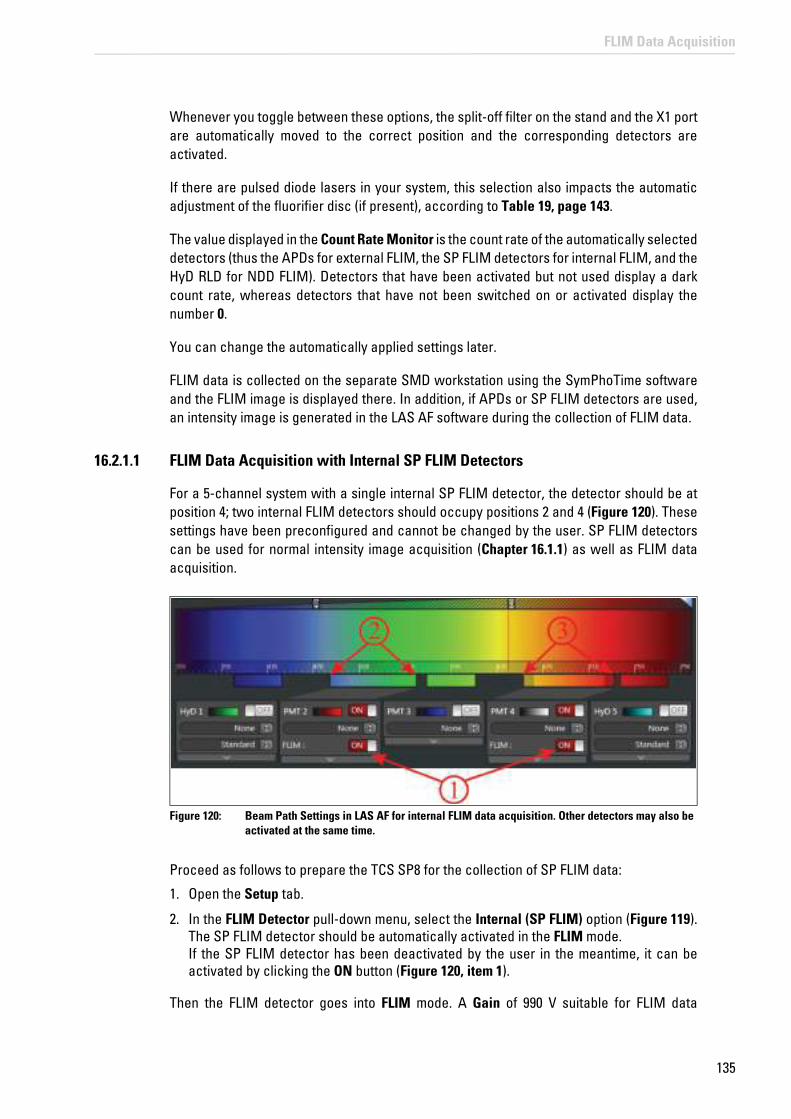
135
FLIM Data Acquisition
Whenever you toggle between these options, the split-off filter on the stand and the X1 port are automatically moved to the correct position and the corresponding detectors are activated.
If there are pulsed diode lasers in your system, this selection also impacts the automatic adjustment of the fluorifier disc (if present), according to Table 19, page 143.
The value displayed in the Count Rate Monitor is the count rate of the automatically selected detectors (thus the APDs for external FLIM, the SP FLIM detectors for internal FLIM, and the HyD RLD for NDD FLIM). Detectors that have been activated but not used display a dark count rate, whereas detectors that have not been switched on or activated display the number 0.
You can change the automatically applied settings later.
FLIM data is collected on the separate SMD workstation using the SymPhoTime software and the FLIM image is displayed there. In addition, if APDs or SP FLIM detectors are used, an intensity image is generated in the LAS AF software during the collection of FLIM data.
16.2.1.1 FLIM Data Acquisition with Internal SP FLIM Detectors
For a 5-channel system with a single internal SP FLIM detector, the detector should be at position 4; two internal FLIM detectors should occupy positions 2 and 4 (Figure 120). These settings have been preconfigured and cannot be changed by the user. SP FLIM detectors can be used for normal intensity image acquisition (Chapter 16.1.1) as well as FLIM data acquisition.
Figure 120: Beam Path Settings in LAS AF for internal FLIM data acquisition. Other detectors may also be activated at the same time.
Proceed as follows to prepare the TCS SP8 for the collection of SP FLIM data:
1. Open the Setup tab.
2. In the FLIM Detector pull-down menu, select the Internal (SP FLIM) option (Figure 119). The SP FLIM detector should be automatically activated in the FLIM mode. If the SP FLIM detector has been deactivated by the user in the meantime, it can be activated by clicking the ON button (Figure 120, item 1).
Then the FLIM detector goes into FLIM mode. A Gain of 990 V suitable for FLIM data

136
FLIM Data Acquisition
acquisition is applied to the detectors. In other words, the gain cannot be changed as long as FLIM is selected.
3. Select a suitable range for spectral detection by adjusting the spectral sliders of the SP FLIM detectors accordingly (Figure 120, item 2 and 3).
At the same time, additional detectors can be activated and used for intensity image acquisition. The data of these additional detectors is used for the intensity image acquisition, but not for FLIM.
4. If you do not obtain an image, check that the X1 port is in the Mirror position.
5. Check to ensure that the fluorifier disc is in a suitable position that blocks excitation light (see Chapter 16.2.3).
16.2.1.2 FLIM Data Acquisition with External MPD APDs
Proceed as follows to prepare the TCS SP8 for collecting FLIM data using external APDs:
1. Switch the APDs on electrically.
2. Select a suitable spectral range for the detection by choosing the appropriate SMD filter cube and mount it in the X1 port adapter (see Chapter 23).
3. Open the Setup tab.
4. In the FLIM detector pull-down menu, select the External option (Figure 121, item 1). In Beam Path Settings, the APDs should be selected automatically (Figure 121, item 2).
Overload protection for internal SP FLIM detectors
If too much light strikes a FLIM detector, it is temporarily switched off to prevent damage and automatically switched back on after a few seconds. If the detector count rate is not reduced, the detectors will continuously switch off and back on, resulting in horizontal streaks in the image. The overload protection of the internal FLIM detectors is active in FLIM mode and image acquisition mode. To avoid streaking, reduce the detector count rate. This can be done in a number of ways:
• Reduce the laser intensity
• Reduce the Gain (possible in image acquisition mode only)
• Reduce the Pinhole
• Use specimens with less intensive fluorescent dye

137
FLIM Data Acquisition
Figure 121: Selecting external APDs for FLIM data acquisition
5. If the APDs still have not been activated in Beam Path Settings, click the buttons allocated to the APDs and set them to ON.
6. Deactivate the internal photomultipliers. Internal photomultipliers cannot be used for imaging simultaneously with APD detection.
7. If no image is displayed, check whether the --- option is set at X1 Port (Figure 121, item 3).
8. Activate at least one detector (APD), even if no image in LAS AF is required. If no detector is activated in LAS AF at all, it will not be possible to start a scanning operation.
16.2.1.3 FLIM Data Acquisition with External Photomultiplier
Proceed as follows to prepare the TCS SP8 for the collection of FLIM data using an external photomultiplier:
1. Switch on the photomultiplier electrically.
2. Select a suitable range for spectral detection by choosing the appropriate SMD filter
Dependency of the spectral detection range of the APDs
The spectral detection range of the APDs is determined by the SMD filter cube used, not by the slider settings for the photomultipliers.
Overload protection for external APDs
APDs are deactivated when emission intensity gets too high. MPD APDs (SPADs) have to be manually reactivated. To do so, refer to the corresponding manuals of the APD unit or the DSN. PE APDs activate automatically. Reduce the incident light on the APD.

138
FLIM Data Acquisition
cube and mount it in the X1 port adapter (Chapter 23).
In LAS AF, a simulator photomultiplier is activated. This means that no image from the external photomultiplier will be displayed in LAS AF.
3. Internal photomultipliers cannot be used for image acquisition simultaneously with external PMT detection. Deactivate the internal PMTs in LAS AF.
4. If no FLIM image is displayed in the SymPhoTime software, check whether the --- option is set at X1 Port (Figure 121, item 3).
Activating the external PMT
Since the signal from the external FLIM PMT is not transferred to the TCS SP8, only a black intensity image is displayed in LAS AF. Despite this, let the external detector remain activated. If no detector is selected at all, it will not be possible to start a scanning operation.
16.2.1.4 FLIM Data Acquisition with Detectors at NDD Position (HyD RLD)
HyD RLD can only be used if the excitation occurs via an MP laser. They can be used for the intensity image acquisition in LAS AF as well as for the FLIM data acquisition in SymPhoTime.
Follow these steps for FLIM data acquisition:
1. Switch the HyD RLD on as described in Chapter 13.3 before starting the scanner and LAS AF. Observe this sequence, since otherwise the cooling for the detectors is not initialized.
2. Select a suitable spectral range for detection by choosing the appropriate NDD filter cube and mounting it in the NDD detection unit.
3. Go to the Setup tab in the Setup FLIM step.
4. In the FLIM Detector dialog, select the Non-descanned (MP FLIM) option. In Beam Path Settings, the HyD RLD should be selected automatically. If that is not the case, activate the detectors in Beam Path Settings with ON (Figure 122).
Dependency of the spectral detection range of the photomultiplier
The spectral detection range of the photomultiplier is determined by the SMD filter cube used, not by the slider settings for the photomultipliers.
Prevent light incidence during MP FLIM measurement
During an MP FLIM measurement (particularly with HyD RLD), the light in the room should be switched off and the shutter of the fluorescence lamp should be closed. Furthermore, the iris diaphragm on the condenser should be completely closed.

139
FLIM Data Acquisition
Figure 122: Selecting external HyD RLD for FLIM data acquisition
5. Deactivate the internal detectors. Internal spectral detectors cannot be used simultaneously with HyD RLD.
6. If no image is displayed, check on the stand display whether a decoupling mirror from the stand is in the RLD/TLD position. If not, set the filter cube on the stand to this position.
7. Activate at least one detector, even if no image in LAS AF is required. If no detector is activated in LAS AF at all, it will not be possible to start a scanning operation.
Overload protection for HyD RLD
HyD RLDs are temporarily deactivated when emission intensity gets too high. They switch back on automatically the next time a scan starts. Beforehand, reduce the incident light on the detector.
Dependency of the spectral detection range of the HyD RLD
The spectral detection range of the HyD RLD is determined by the NDD filter cube used, not by the slider settings for the photomultipliers.

140
FLIM Data Acquisition
Cooling of HyD RLDs: To achieve the minimum dark count rate and thereby optimum performance, the HyD RLDs are actively cooled. You can read the cooling status in the Setuptab in the Detection Unit Cooling State dialog (Figure 123). The colors here mean:
• Red: Detector is warm
• Yellow: Detector is cooling now
• Green: Detector has reached its optimum operating temperature
Figure 123: Cooling status of the HyD RLD
16.2.2 Selecting Laser Lines for FLIM
16.2.2.1 Do Not Use Continuous Wave VIS Lasers
Close the corresponding shutter (Figure 124, item 1) for continuous wave lasers in Beam Path Settings and move all AOTF slider settings to 0 (Figure 124, item 2).
Safety shut-off of the cooling system
The cooling system has a safety shut-off: If the humidity is too high, the cooling system switches off to prevent condensation from forming on the detector.
Use pulsed lasers for FLIM data acquisition
For FLIM, only pulsed lasers can be used. Continuous wave laser excitation must be disabled, since it disrupts the FLIM data acquisition.

141
FLIM Data Acquisition
Figure 124: Beam Path Settings in LAS AF: Activating the continuous wave VIS lasers
If the system has an FCS filter wheel, its setting is irrelevant for FLIM, as it is directly in front of the argon laser and thus does not affect the pulsed excitation.
16.2.2.2 Using Pulsed Diode Lasers (UV, VIS)
• For external FLIM with APDs or an external photomultiplier: Follow the instructions in Chapter 15.1. The fluorifier disc can be set to Empty as needed. If additional suppression of the excitation light is desired, follow the recommended settings in Table 19.
• For internal SP FLIM with SP FLIM detectors: Check the setting of the fluorifier disc. It contains an additional barrier filter that prevents excitation light from hitting the SP detection module. Recommended settings are given in Table 19 in Chapter 16.2.3.
16.2.2.3 Using MP Lasers
• For external FLIM at the X1 port and for internal FLIM: Follow the instructions in Chapter 15.1. With the fluorifier disc, an MP filter block has to be selected (SP680 or SP700); the pinhole should be open as far as possible.
• For FLIM detection at NDD position (HyD RLD): The setting of the fluorifier disc, X1 port, and pinhole play no role.
Prevent light incidence during MP FLIM measurement
During an MP FLIM measurement (particularly with HyD RLD), the light in the room should be switched off and the shutter of the fluorescence lamp should be closed. Furthermore, the iris diaphragm on the condenser should be completely closed.
No additional pulsed laser 470 or 640 for MP systems
Systems equipped with an MP laser cannot be complemented with a pulsed 440, 470, or 640-nm laser.
142
FLIM Data Acquisition
16.2.2.4 Using White Light Lasers
1. To activate the laser, follow the instructions in Chapter 15.1. In general we recommend using the filters available in the fluorifier disc.
2. If the white light laser is used as an excitation source for FLIM measurements, always use only one wavelength per FLIM measurement.
16.2.3 Adjusting the Fluorifier Disc
With the Show Fluorifier Settings button (Figure 125), you can call up the Fluorifier Disc Settings dialog to select a barrier filter or set a polarization angle.
16.2.3.1 Setting for SP FLIM
SMD systems equipped with SP FLIM detectors have a fluorifier disc with barrier filters for the excitation light. These filters prevent reflected excitation light from hitting the SP module.
Alternative selection of UV and MP FLIM excitation
Some systems feature both a pulsed diode laser (405 nm) and an MP laser. Only one of these two lasers can be used for FLIM at a time. Make sure that the correct synchronization cable is connected to the TCSPC unit PicoHarp 300 at channel 0. When changing between MP and 405 nm excitation for FLIM, you must also change the synchronization cable connected to the PicoHarp.
Alternative selection of excitation from a white light laser, pulsed diode, or MP FLIM
Some systems feature not only a white light laser, but also a pulsed laser and/or an MP laser. Only one of these three laser options can be used for FLIM at a time. Make sure that the correct synchronization cable is connected to the TCSPC unit PicoHarp 300 at channel 0. When changing between MP, white light laser, or diode laser for FLIM, you must also change the synchronization cable connected to the PicoHarp.

143
FLIM Data Acquisition
Recommended settings of the fluorifier disc for SP FLIM detection:
Table 19: Recommended settings for Fluorifier disc for SP FLIM
As long as the Fluorifier Disc Auto Select is active in the dialog window, the position of the Fluorifier disc is automatically set. It can be changed by the user if Auto Select is disabled. To do so, proceed as follows:
1. In Beam Path Settings, click on the Fluorifier Disc button (Figure 125).
Figure 125: Fluorifier Disc button in Beam Path Settings
The following dialog box opens:
Figure 126: Fluorifier Disc Settings
Excitation laser line Recommended setting of the fluorifier disc
1 405 Barrier filter 405/640
2 405+470 Barrier filter 405/470
3 405+ 640 Barrier filter 405/640
4 470 Barrier filter 405/470
5 470+640 Barrier filter 470/640
6 640 Barrier filter 405/640 or 470/640
7 MP SP680 or SP700
8 WLL Depending on the selected white light laser wavelength, there are barrier filters for: 488, 514, 561, 594, or 633

144
FLIM Data Acquisition
2. Click the upper radio button (Figure 126, item 1).
3. Filter selection:
• For automatic filter selection: Select the Auto Select (Figure 126, item 3) check box. Individual filters now cannot be manually selected.
• For manual filter selection: Remove the check in the Auto Select check box. From the filter list, select the suitable filter.
16.2.3.2 Setting for External FLIM or Intensity Image Acquisition
For external FLIM detection or normal intensity image acquisition, it is possible to use the Empty position (Figure 126, item 2) as needed in the Fluorifier Disc Settings. Remove the check in the Auto Select check box and select Empty in both menus.
Alternatively, if the effect of polarization is to be investigated, the lower radio button can be clicked (Figure 126, item 4) and the polarization direction defined by moving the slider position.
16.2.3.3 Setting for FLIM White Light Laser
If the white light laser is used as an excitation source, it is recommended - independent of the detectors used - to use the filters of the fluorifier disc and, thereby, to select the corresponding laser wavelengths (usually 488, 514, 561, 594, and 633 nm, Figure 127).
Figure 127: Selecting the laser lines for FLIM white light lasers
Selection switches to set the laser wavelength and the filter wheel can be found in the Setup FLIM and Measurements steps on the Acquisition tab (Figure 128).
o
Figure 128: Selection switches to set the laser wavelength and the filter wheel when using the white light laser

145
FLIM Data Acquisition
If you would like to use other wavelengths for excitation, the filter wheel should be in the Empty position (Figure 126, item 2).
16.2.4 Changing the Pulse Frequency for Pulsed Diode Lasers (405, 440, 470, 640 nm)
The frequency is controlled using LAS AF. The corresponding signal is transferred from the scan head via the pulse interface to the laser driver PDL or Sepia.
1. Make sure that the laser driver is set to external trigger.
2. In Beam Path Settings, in the area for controlling the pulsed lasers, select the desired frequency in the pull-down menu (Figure 129). The default setting is 40 MHz.
Figure 129: Beam Path Settings in LAS AF: Activating a pulsed diode laser and selecting the laser pulse rate.
After changing the frequency, it may be necessary to change the time resolution of the data acquisition in SymPhoTime. You can change the resolution in the oscilloscope window of the SymPhoTime software as follows:
3. Select Show Oscilloscope... in SymPhoTime.

146
FLIM Data Acquisition
The following window is displayed:
Figure 130: Oscilloscope window in SymPhoTime
4. In the Acquisition field, you can change the resolution under resol. Please confirm the settings by selecting apply. To cover the whole range between two consecutive laser pulses at the maximum resolution possible, the following settings are recommended:
Table 20: Recommended resolution for data acquisition with different laser frequencies
The default is a setting of 16 ps suitable for a laser repetition rate down to 20 MHz.
16.2.5 2-Laser PIE (405, 470, 640 nm)
PIE (pulsed interleaved excitation) means that two lasers pulse alternatingly. This method is used to identify crosstalk and cross excitation and remove them from the signal. In the SMD system, this option is available for certain combinations of pulsed diode lasers (405+470, 405+640, 470+640). Exactly two diode lasers have to be selected in order to activate 2-laser PIE. If this is not the case, the corresponding radio button is grayed out.
Laser frequency Resolution of data acquisition
80 MHz (MP laser, white light laser) 4 ps
40 MHz (pulsed diode laser, white light laser) 8 ps
20 MHz (pulsed diode laser, white light laser) 16 ps
10 MHz (pulsed diode laser, white light laser) 32 ps
5 MHz (pulsed diode laser) 64 ps

147
FLIM Data Acquisition
Enable the PIE function by clicking on the 2-laser PIE (Figure 131) button.
Select the base frequency in the pull-down menu. The frequency of both lasers is shown as a PIE frequency (Figure 132). it is half as high as the base frequency.
Figure 131: Beam Path Settings in LAS AF: Activating exactly two pulsed diode lasers
Figure 132: Dialog for selecting the laser pulse rate in the PIE mode; both lasers pulse at half the base frequency
Selecting 2-laser PIE is not possible when activating a pulsed diode laser or when selecting three pulsed diode lasers, and the corresponding button is grayed out (Figure 133).
Figure 133: Activating a pulsed diode laser; the radio button for 2-laser PIE is grayed out
16.2.6 Changing Pulse Frequency for White Light Lasers
If a white light laser has a pulse picker, the repetition rate can be selected via a pull-down menu in Beam Path Settings in LAS AF (Figure 134). The laser is at 80 MHz when starting the system. In the pull-down menu, you can select the following frequencies: 80, 40, 20 and 10 MHz.
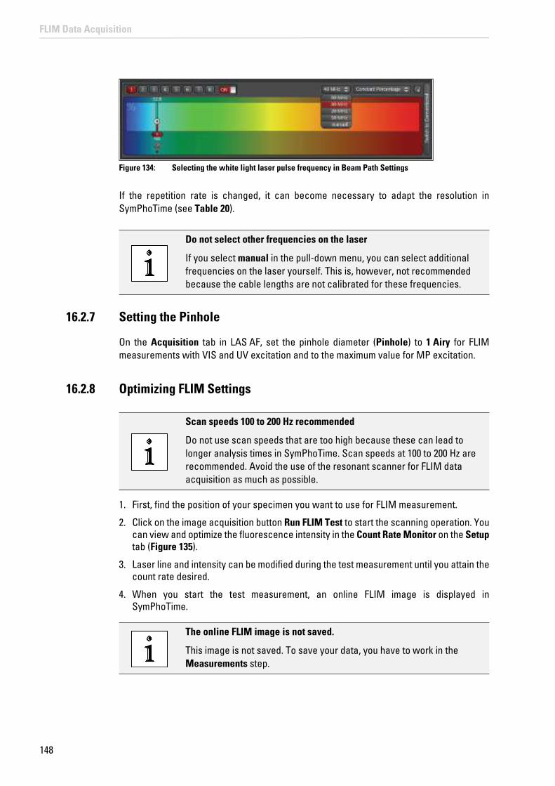
148
FLIM Data Acquisition
Figure 134: Selecting the white light laser pulse frequency in Beam Path Settings
If the repetition rate is changed, it can become necessary to adapt the resolution in SymPhoTime (see Table 20).
16.2.7 Setting the Pinhole
On the Acquisition tab in LAS AF, set the pinhole diameter (Pinhole) to 1 Airy for FLIM measurements with VIS and UV excitation and to the maximum value for MP excitation.
16.2.8 Optimizing FLIM Settings
1. First, find the position of your specimen you want to use for FLIM measurement.
2. Click on the image acquisition button Run FLIM Test to start the scanning operation. You can view and optimize the fluorescence intensity in the Count Rate Monitor on the Setuptab (Figure 135).
3. Laser line and intensity can be modified during the test measurement until you attain the count rate desired.
4. When you start the test measurement, an online FLIM image is displayed in SymPhoTime.
Do not select other frequencies on the laser
If you select manual in the pull-down menu, you can select additional frequencies on the laser yourself. This is, however, not recommended because the cable lengths are not calibrated for these frequencies.
Scan speeds 100 to 200 Hz recommended
Do not use scan speeds that are too high because these can lead to longer analysis times in SymPhoTime. Scan speeds at 100 to 200 Hz are recommended. Avoid the use of the resonant scanner for FLIM data acquisition as much as possible.
The online FLIM image is not saved.
This image is not saved. To save your data, you have to work in the Measurements step.

149
FLIM Data Acquisition
5. If you want to view an online lifetime histogram, close the fast FLIM image in SymPhoTime. Click the symbol Show Oscilloscope... and select the TCSPC histogramtab.
6. To cancel specimen illumination, select the Stop FLIM Test button in the LAS AF software. This will also stop the online FLIM display in SymPhoTime.
The instrument parameters set for the FLIM measurements (laser lines and associated intensity, pinhole, scan mode, image size etc.) are kept as separate FLIM settings that are independent from the image acquisition setting defined in the Setup Imaging step. The FLIM settings defined in the Setup FLIM step are automatically transferred to the Measurementsstep.
16.2.9 Count Rate Monitor
The count rate of each channel is displayed in the Setup tab. For FLIM, the count rate should be between 10,000 and 1,000,000 cps (counts per second).
Figure 135: Count rate monitor in the FLIM Wizard
In addition, the count rate monitor shows the number of photons in the brightest pixel of the image. This value allows you to evaluate the image quality. The higher the number of fluorescence photons (counts) per pixel, the more accurately the lifetime can be determined. This value is updated regularly whenever a new scanning operation starts in the Setup FLIM step of the FLIM Wizard.
16.2.10 Loading and Saving FLIM-specific Instrument Parameter Settings
The instrument parameter setting (IPS) for FLIM can be saved and loaded in the same way as IPSs for normal intensity imaging.
Save the FLIM settings in the Setup FLIM step and settings for intensity image acquisition in the Setup Imaging step.

150
FLIM Data Acquisition
You can also load FLIM instrument parameter settings in the Setup Imaging step or outside the FLIM Wizard. In this case, these settings are treated as settings for normal image capture intensities.
16.3 Measurements Step – Time Series for FLIM Measurement at Multiple Points
After optimizing the FLIM measurement conditions, it is possible to have FLIM measurements run automatically. To do so, go to the Measurements step.
16.3.1 FLIM Network Connection
The LAS AF and SymPhoTime programs are synchronized via a network connection. Each FLIM measurement started in LAS AF in the Measurements step of the FLIM Wizard generates a new data file in SymPhoTime.
In addition to the synchronization, the network also enables the automatic transmission and implementation of scan parameters (format, scan speed, unidirectional or bidirectional scanning). In addition, other relevant information, such as the file name, instrument parameter setting (IPS) or comments entered by the user in LAS AF are transferred and stored in SymPhoTime.
During the FLIM measurement, an online FLIM image is displayed that is automatically saved along with the raw data in SymPhoTime. After the data acquisition, a more detailed data analysis can then be carried out offline.
16.3.2 Definition of the FLIM Measurement File Names Transferred to SymPhoTime
1. Select the Setup tab.
2. Enter the name of the FLIM data file used in SymPhoTime in the Base name field in the pull-down menu File/Series Definitions (Figure 136).
Observe the SymPhoTime manual
For more detailed information about data analysis, refer to the SymPhoTime manual.
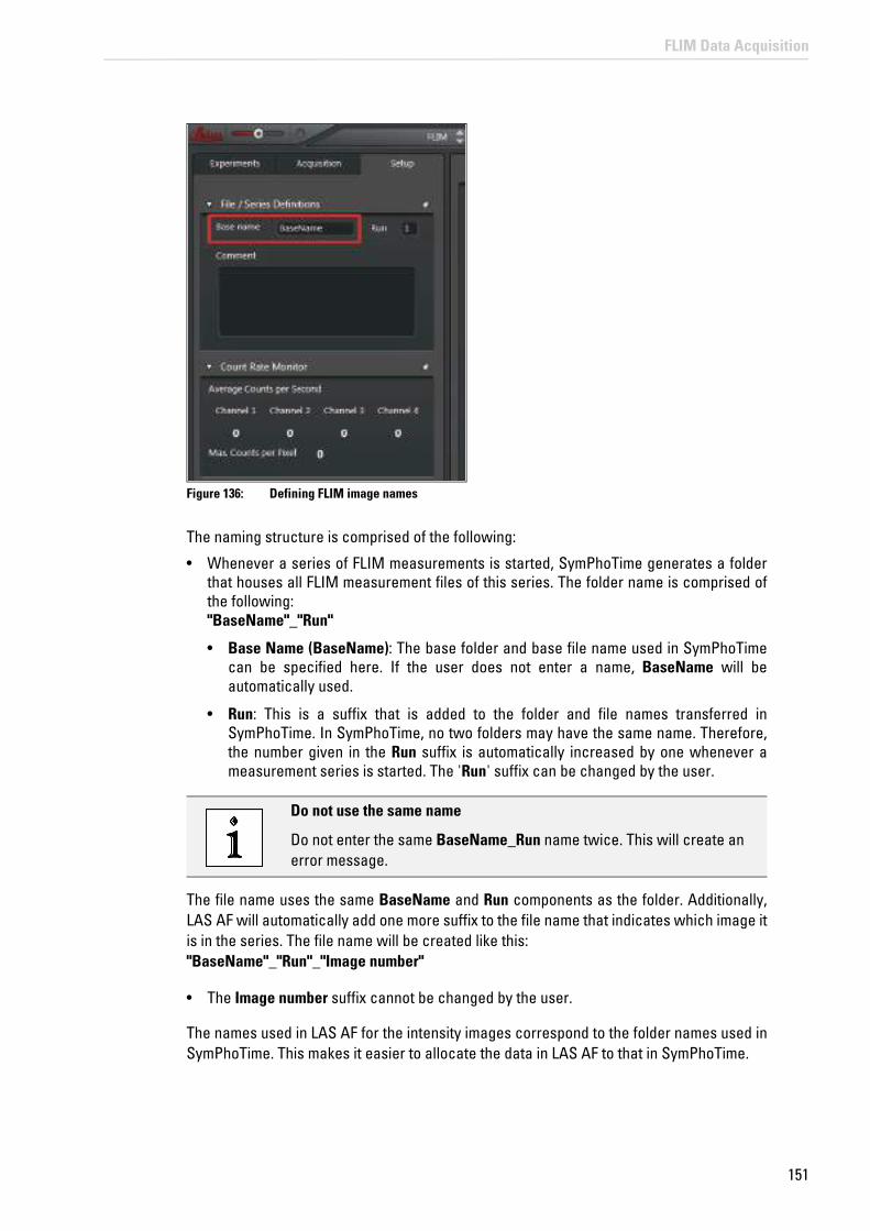
151
FLIM Data Acquisition
Figure 136: Defining FLIM image names
The naming structure is comprised of the following:
• Whenever a series of FLIM measurements is started, SymPhoTime generates a folder that houses all FLIM measurement files of this series. The folder name is comprised of the following: "BaseName"_"Run"
• Base Name (BaseName): The base folder and base file name used in SymPhoTime can be specified here. If the user does not enter a name, BaseName will be automatically used.
• Run: This is a suffix that is added to the folder and file names transferred in SymPhoTime. In SymPhoTime, no two folders may have the same name. Therefore, the number given in the Run suffix is automatically increased by one whenever a measurement series is started. The 'Run' suffix can be changed by the user.
The file name uses the same BaseName and Run components as the folder. Additionally, LAS AF will automatically add one more suffix to the file name that indicates which image it is in the series. The file name will be created like this: "BaseName"_"Run"_"Image number"
• The Image number suffix cannot be changed by the user.
The names used in LAS AF for the intensity images correspond to the folder names used in SymPhoTime. This makes it easier to allocate the data in LAS AF to that in SymPhoTime.
Do not use the same name
Do not enter the same BaseName_Run name twice. This will create an error message.

152
FLIM Data Acquisition
16.3.3 Defining a Single FLIM Image
To acquire a single FLIM image, proceed as follows:
1. Select the specimen position.
2. Select either the Acquisition Mode xyz or xzy as a scan mode in step Setup FLIM on the Acquisition tab. Optimize the instrument parameter setting for FLIM measurement.
Figure 137: Selecting a scan mode
3. Select a suitable format. The maximum possible size is 512 x 512.
4. Go to the Measurements step in the FLIM Wizard.
5. Define a file name (see Chapter 16.3.2) in the Setup tab.
6. Open the Acquisition tab. Do not activate the stack dialog for acquiring an individual image.

153
FLIM Data Acquisition
Figure 138: Defining a single FLIM image
7. In the Defining FLIM Image acquisition time dialog, you can define the duration of the acquisition of the individual image (Figure 138). To improve FLIM data statistics, multiple scanning operations are normally carried out with the specimen and the data is compiled into a final image. The following alternative options are possible:
• Duration of each image: You can enter how long the data acquisition of an individual FLIM image is to last. The corresponding number of scanning operations are carried out on the specimen. The entered duration is corrected automatically so that a scanning operation is always stopped at the end of an image.
• Repetitions: Enter the number of scans to be carried out.
• Acquire until max ___ photons/pixel: With this option, the data acquisition is not stopped at a fixed point in time. Image acquisition ends if the brightest pixel contains more photons than specified here. With this option, images with comparable brightness and therefore comparable photon statistics can be acquired.
8. Start FLIM measurement by clicking on the image acquisition button Run FLIM.
In LAS AF, an image averaged across the entire measurement duration is shown.
16.3.4 Defining an xyz or xzy FLIM Stack
To acquire an FLIM stack, proceed as follows:
1. Select the specimen position.
2. In the Setup FLIM step on the Acquisition tab, select either the Acquisition Mode xyz or xzy as the scan mode (Figure 137). Optimize the instrument parameter setting for FLIM measurement.
3. Go to the Measurements step in the FLIM Wizard.
4. Define a file name (see Chapter 16.3.2) in the Setup tab.
5. Open the Acquisition tab.

154
FLIM Data Acquisition
6. Define the first and last image of the stack and the number of planes via the stack dialog (z-stack or y-stack) (Figure 139).
Figure 139: FLIM stack definition xzy
7. Define the duration of the individual FLIM images as described in Chapter 16.3.3. The option Acquire until max ___ photons/pixel is of particular interest for acquiring FLIM stacks. It enables corrections due to intensity changes caused by different sample penetration depths.
8. Start the FLIM stack acquisition with the image acquisition button Run FLIM.
In LAS AF, you obtain a stack of averaged images and, in SymPhoTime, a series of FLIM images.
16.3.5 Defining an FLIM Time Series
To acquire an FLIM stack, proceed as follows:
1. Select the specimen position.
2. Select either Acquisition Mode xyt or xzt as the scan mode on the Acquisition tab. Optimize the instrument parameter setting for FLIM measurement.
3. Define a file name in the Setup tab (Chapter 16.3.2).
4. Open the Acquisition tab.

155
FLIM Data Acquisition
5. Define the duration of the individual FLIM images as described in Chapter 16.3.3. For recording a FLIM time series, use either Duration of each image or Repetitions, because the last option, (Acquire until max ___ photons/pixel), does not allow a fixed period of time to be specified.
6. You can define a time series using the time series dialog (Figure 140). The following inputs are possible:
• Time Interval: Defines the time between the beginning of one FLIM image and the next image. This duration cannot be shorter than the duration entered for a single FLIM image. To specify the smallest possible duration, select Minimize.
• Duration: Here, enter how long the entire time series is to last. The corresponding number of FLIM images is acquired. The duration entered is automatically corrected so that all FLIM images can be completed.
• Frames: You can specify the number of FLIM images to be acquired. The maximum specified number is 1000.
Figure 140: Defining an FLIM time series
7. Enter the desired value in the time series dialog.
8. Start the FLIM time series acquisition with the image acquisition button Run FLIM.
In LAS AF, you obtain a time series of averaged images and, in SymPhoTime, a series of FLIM images.
16.3.6 Defining a Time Series of xyz or xzy FLIM Stacks
Proceed as follows to take a time series of FLIM stacks:
1. Select the specimen position.
2. Select either Acquisition Mode xzyt or xyzt as the scan mode on the Acquisition tab. Optimize the instrument parameter setting for FLIM measurement.

156
FLIM Data Acquisition
3. Define a file name in the Setup tab (Chapter 16.3.2).
4. Open the Acquisition tab. Via the stack dialog, you define the first and last image of the stack and the number of planes (Figure 139).
5. Define the duration of the individual FLIM images as described in Chapter 16.3.3. Use either Duration of each image or Repetitions, because the last option, Acquire until max ___ photons/pixel, does not allow a fixed period of time to be specified.
6. You can define a time series using the time series dialog (Figure 141). The following inputs are possible:
• Time Interval: defines the duration between the beginning of an FLIM stack and the next stack. This time span cannot be shorter than the timespan required for an individual FLIM stack. To specify the smallest possible duration, select Minimize.
• Duration: Here, enter how long the entire time series is to last. The corresponding number of FLIM stacks is acquired. The entered duration is automatically corrected so that the last FLIM stack can be completed.
• Stacks: Here, you can specify the number of FLIM stacks to be acquired. The maximum specified number of FLIM images is 1000.
Figure 141: Defining a time series of xyzt FLIM stacks

157
FLIM Data Acquisition
7. Enter the desired value in the time series dialog.
8. Start the FLIM experiment recording with the Run FLIM button.
In LAS AF, you obtain a time series of averaged images of stacks and, in SymPhoTime, a series of FLIM images.
16.3.7 Defining an xyλ or xzλ FLIM Stack
These modes are only available for systems that are equipped with internal SP FLIM detectors. During the generation of stacks, the spectral sliders of the SP FLIM detectors are shifted incrementally. To acquire an FLIM stack, proceed as follows:
1. Select the specimen position.
2. In the Setup FLIM step on the Setup tab, select the Internal (SP FLIM) option (Chapter 16.2.1).
3. In the Measurements step on the Acquisition tab, select either the Acquisition Modexyλ or xzλ as the scan mode. Optimize the instrument parameter setting for FLIM measurement.
4. Define a file name in the Setup tab (Chapter 16.3.2).
5. Open the Acquisition tab. If the correct SP FLIM detector is not yet selected, select it in the PMT-Selection line. In Beam Path Settings, the detector selection cannot be changed.
6. Define the stack in the λ stack dialog as follows (Figure 142):
• Detection Begin and Detection End: Wavelength of the first and last FLIM image
• Detection Band Width: Width of the spectral range of an individual FLIM image
• No. of Detection Steps: Number of FLIM images that are acquired from different spectral ranges
• -Detection Stepsize: Step size of the spectral slider from one image to the next
λ
λ

158
FLIM Data Acquisition
Figure 142: Defining xy FLIM stacks
7. Define the duration of the individual FLIM images as described in Chapter 16.3.3. If all images are to have a comparable brightness, use the Acquire until max ___ photons/pixel option. It enables corrections of intensity changes which are caused by the emissions spectrum and by bleaching artefacts. If spectral intensity information is required, use Duration of each image or Repetitions.
8. Start the FLIM stack acquisition with the image acquisition button Run FLIM.
In LAS AF, you obtain a λ stack of averaged images and, in SymPhoTime, a series of FLIM images.
16.3.8 Defining a Time Series of xyλ or xzλ FLIM Stacks
These modes are only available for systems that are also equipped with internal SP FLIM detectors.
1. Select the specimen position.
2. In the Setup FLIM step on the Setup tab, select the Internal (SP FLIM) option (Chapter 16.2.1).
3. In the Measurements step on the Acquisition tab, select either the Acquisition Modexyλ t or xzλ t as the scan mode. Optimize the instrument parameter setting for FLIM measurement.
4. Define a file name in the Setup tab (Chapter 16.3.2).
5. Open the Acquisition tab. If the correct SP FLIM detector is not yet selected, select it in the PMT-Selection line. In Beam Path Settings, the detector selection cannot be changed.
λ

159
FLIM Data Acquisition
6. Via the λ stack dialog, define the stack as described in Chapter 16.3.7 (Figure 142).
7. Define the duration of the individual FLIM images as described in Chapter 16.3.3. Use either Duration of each image or Repetitions, because the last option, Acquire until max ___ photons/pixel, does not enable the specification of a fixed period of time.
8. You can define a time series using the time series dialog (Figure 143). The following inputs are possible:
• Time Interval: Defines the duration between the beginning of an FLIM stack and the next stack. This time span cannot be shorter than the timespan required for an individual FLIM stack. To specify the smallest possible duration, select Minimize.
• Duration: Here, enter how long the entire time series is to last. The corresponding number of FLIM stacks is acquired. The entered duration is automatically corrected so that the last FLIM stack can be completed.
• Stacks: Here, you can specify the number of FLIM stacks to be acquired. The maximum specified number of FLIM images is 1000.
Figure 143: Defining a time series of xz FLIM stacks
λ
λ
λλ
λ
λ

160
FLIM Data Acquisition
9. Start the FLIMλ stack acquisition with the image acquisition button Run FLIM.
In LAS AF, you obtain a λ stack of averaged images and, in SymPhoTime, a series of FLIM images.
16.3.9 Defining an xyΛ or xzΛ FLIM Stack
These modes are only available for systems that are equipped with variable-frequency lasers (white light lasers, MP lasers). In the following, the acquisition of xy or xz FLIM stacks with the white light laser is described:
1. Select the specimen position.
2. In Beam Path Settings in the white light laser dialog, select the mode Constant Power(Figure 144).
Figure 144: Selecting the Constant Power mode
3. In the Setup FLIM step on the Setup tab, select the option Internal (SP FLIM) or External (Chapter 16.2.1).
4. In the Measurements step on the Acquisition tab, select either the Acquisition ModexyΛ or xzΛ as the scan mode.
5. Check that the correct detector for the FLIM measurement is activated in the Λ stack dialog.
6. Optimize the instrument parameter setting for FLIM measurement. While doing so, test different excitation wavelengths.
7. Define a file name in the Setup tab (Chapter 16.3.2).
8. Open the Acquisition tab. If you want to use a spectral internal FLIM detector, select it in the PMT Selection field (Figure 146). If you remove the check next to Automatic SP Movement, you can manually select the external detector manually with white light or MP laser excitation in Beam Path Settings.
Λ Λ

161
FLIM Data Acquisition
Figure 145: Select the detector in Beam Path Settings
9. Define the stack in the Λ stack dialog as follows (Figure 146):
• Excitation Begin and Excitation End: Excitation wavelength of the first and last FLIM image
• No. of Excitation Steps: Number of FLIM images that are taken from the different excitation wavelengths
• Excitation Stepsize: Step size of the excitation wavelength from one image to the next
Figure 146: Defining xy FLIM stacks
Λ
Λ

162
FLIM Data Acquisition
10. Define the duration of the individual FLIM images as described in Chapter 16.3.3. If all images are to have a comparable brightness, use the Acquire until max ___ photons/pixel option. It enables corrections of intensity changes which are caused by the excitation spectrum and by bleaching artefacts. If intensity information is required, use Duration of each image or Repetitions.
11. Start the FLIM stack acquisition with the image acquisition button Run FLIM.
In LAS AF, you obtain a Λ stack of time-averaged images and, in SymPhoTime, a series of FLIM images.
16.3.10 Control of FLIM Measurements
The measurement series is started by clicking on the Start FLIM image acquisition button. It stops automatically after all measurements are taken. A user-defined stop is possible by clicking the Stop FLIM image acquisition button.
In the count rate monitor (Figure 147), the current count rate (in cps - counts per second) is displayed during the individual measurements. In the line Max. counts per pixel, the total number of photons accumulated so far in the brightest pixel of the image is shown. This gives an initial indication as to whether the photon statistics in the image are sufficient.
After start of the FLIM series, fast FLIM images are displayed in SymPhoTime online and saved together with the raw data.
Both the count rate and fast FLIM images give a first impression about the quality of the measurements.
Figure 147: Count rate monitor in the Measurements step of the FLIM Wizard

163
Summarized manual for FLIM experiments
17 Summarized Manual for FLIM Experiments
17.1 Prerequisites
The following description assumes that the following prerequisites are met:
• SymPhoTime has been started and a workspace has been loaded.
• LAS AF was started.
• All components (lasers, detectors, software) of the PicoQuant SMD upgrade are switched on. Detailed information on starting the components can be found inChapter 13.4.
• The right objective is chosen with high numerical aperture and - if present - the correction ring is adjusted to the specimen used (Chapter 18.1.1 and Chapter 18.1.4).
• Your specimen is already placed onto the microscope and brought into focus.
• The selected excitation lasers are switched on and activated (Chapter 15).
• The correct emission filter(s) was placed in front of the detectors. For external FLIM detectors, the correct SMD filter cube has to be set in the X1 port adapter (Chapter 23); for internal SP FLIM detection, the barrier filter in the fluorifier disc is used (Chapter 16.2.3). With HyD RLD, the correct barrier filter and a suitable filter cube must be used in the detector unit.
• For beam splitter systems: The correct beam splitter for your wavelength has been selected in LAS AF. If pulsed diode lasers are used, the beam splitter is to be in the Substrate position.
• With AOBS systems: The acousto-optical beam splitter is in fluorescence mode.
17.2 Selecting Position for the FLIM Measurement
1. Start the Wizard in LAS AF by selecting the FLIM operating mode.
2. Scan an image (for this, use the Setup Imaging step in the FLIM Wizard). To be able to get an initial overview, you can use continuous wave lasers and internal detectors.
3. Select the correct sample region at which the FLIM measurement is to be carried out.
17.3 Changing from Continuous to Pulsed Excitation
1. Make sure that the PicoQuant laser driver is set to external trigger.
2. In the FLIM Wizard in LAS AF, go to the Setup FLIM step.
3. Select a suitable laser wavelength for pulsed excitation (Chapter 16.2.2).
4. Check whether the selectable beam splitter for MFP is in the correct position (Chapter 16.2.2).
5. Select the laser pulse frequency (repetition rate) in LAS AF (Chapter 16.2.4). In general, 40 MHz is the best frequency to start with. Lower the frequency to 20 MHz only if you determine that your lifetime decay curve does not fit in the TCSPC histogram. This
164
Summarized manual for FLIM experiments
applies for pulsed diode lasers and white light lasers with a pulse picker only. The repetition rate of multiphoton lasers cannot be adapted (other than with a pulse picker). For details, see Chapter 17.9.
17.4 Changing from Internal Detection on the SP8 to External TCSPC Detectors
1. In the FLIM Wizard in LAS AF, go to step Setup FLIM.
2. If you want to carry out your time-resolved experiments with the external PicoQuant detectors, configure the detection beam path in the scan head to direct the fluorescence to the X1 output port (that means the X1 Port at position ---)(Chapter Chapter 16.2.1 and Chapter 16.2.1.2). This is done automatically when you select the External FLIM detector in the "Setup" tab (Chapter 16.2.1, Figure 119).
3. If you have two single detectors, set the appropriate SMD filter cube inside the X1 port adapter to split the appropriate spectral range of the emission light to the two detectors.
4. Make sure that suitable fluorescence detection filters (band pass / long pass) are present in the corresponding filter holders of the PicoQuant detector unit(s). If the detection filters and beam splitters are already placed inside the X1 port adapter, you can leave the filter holders in front of the detectors empty. However, a filter holder must be located in front of the detector in order to open its shutter.
17.5 Using Internal SP FLIM Detection
1. In the FLIM Wizard in LAS AF, go to step Setup FLIM.
2. Select the FLIM detector Internal (SP FLIM) on the Setup tab (Chapter 16.2.1, Figure 119). This automatically moves the X1 port to the position Mirror that reflects the emission light to the SP detection module within the SP8 scan head.
3. Select a suitable spectral detection range by moving the mirror sliders of the detectors in the Beam Path Settings (Chapter Chapter 16.2.1.1).
4. Check whether the fluorifier disc is in the correct position (Chapter 16.2.3).
17.6 Using FLIM Detectors at the NDD Position (HyD RLD)
1. In the FLIM Wizard in LAS AF, go to step Setup FLIM.
2. Select the FLIM detector Non descanned (MP FLIM) on the Setup tab (Chapter 16.2.1, Figure 119). By doing so, a beam splitter in the stand which decouples the florescent light to the HyD RLD automatically swings into the beam path.
3. Make sure that the correct barrier filter and the suitable filter cube are placed in the
Pay attention to the APD detection unit manual
When using a two-channel APD detector unit from PicoQuant, ensure that the beam splitter in the beam splitter turret is set so that it distributes the emission light to the detectors correctly. Detailed information can be found in the detection unit manual.

165
Summarized manual for FLIM experiments
detector module.
4. Check whether the fluorifier disc is in the correct position (Chapter 16.2.3).
17.7 Setting Suitable Scan Parameters
Determine the correct scan template in LAS AF in the FLIM Wizard's Setup FLIM step. The following settings should be made on the Acquisition tab:
• monodirectional scan (bidirectional scan is only supported for zoom >8)
• maximum 512 x 512 pixels Using a low number of pixels (e.g. 256 x 256) is recommended. With a low number of pixels, more photons can be collected in the individual pixels. In this way, a better allocation of the lifetime data is possible. Even the summary of pixels (binning) is possible later in the analysis range in order to calculate and analyze an image with low number of pixels. This will result in no loss of the acquired fluorescence.
• The averaging mode (as Average or Accumulation) of LAS AF is not accessible within the SMD-FLIM Wizard, because it is not to be used for scanning operations.
• moderate scan speed (100 to 200 Hz) With increasing numbers of acquired individual images, the calculation time increases for all steps of the FLIM analysis. Avoid the use of the resonant scanner for FLIM data acquisition.
17.8 Optimizing the Photon Count Rate
1. In the FLIM Wizard in LAS AF, go to the Setup FLIM step.
2. Start the scanning operation in the test mode by clicking on the image acquisition button Run FLIM Test. Normally, the SymPhoTime software will start the data acquisition and display automatically. You can also start the FLIM data acquisition by selecting the Acquire LSM Measurements button in SymPhoTime.
The Measurement Preview dialog in SymPhoTime software opens on the Image tab (Figure 148, right).
FLIM data is not saved with Run FLIM Test
The Run FLIM Test option is only intended for the optimization of the instrument parameter settings. The corresponding FLIM data is not saved.

166
Summarized manual for FLIM experiments
Figure 148: Online monitoring of the photon count rate in the SymPhoTime preview window. Left: Display of the count rate over time. Right: FLIM image preview specifying the maximum count rate (red rectangle).
3. Make sure that the maximum Peak Count Rate is below the values given in the table below Table 21.
Table 21: Upper count rate limit for FLIM detection with different detectors
The reason for limiting the detection count rate lies in the Pile-up effect that causes an apparently shorter lifetime at high detection count rates.
For example, using a laser repetition frequency of 40 MHz and a detection count rate of 1 MHz leads to an error of below 1 % for the calculated lifetime. At a 3 MHz count rate, the obtained lifetime will be 2 % too low. The error induced by the pile-up effect is proportional to the ratio between the detection count rate and the laser repetition frequency. The maximum measurement count rate is calculated from the maximum of the time tracedisplayed on the tab of the same name (see Figure 148, left). The binning (resolution) should be set to 1 ms. This allows you to see the changes of the count rate over time.
Laser pulse frequency (repetition rate)
Upper count rate limit for different detectors, in [kcounts/s]
PMA photomultiplier or MPD APD (MPD)
PE AQR APD PE APD (AQR)
40 MHz 1000 700
20 MHz 1000 700
10 MHz 500 500
5.0 MHz 250 250
2.5 MHz 125 125

167
Summarized manual for FLIM experiments
4. Make the settings in the Measurement Preview window (such as the selection of the displayed channels, the resolution of the time trace etc.) by selecting the Show Measurement Preview... button in SymPhoTime while no measurement is running. Defaults can be saved using the Set Defaults button.
5. Adjust the photon count rate by changing the intensity of the diode laser at the laser coupling unit (LCU) (Chapter 9.6) or, if you do not have an LCU, but rather a direct fiber coupled laser, in a similar way at the laser scaffold with the intensity regulation knob. Information on attenuation by modifying the laser current can be found in the manual on the laser driver (PDL or SEPIA). Keep in mind that changing the laser intensity via the laser current does alter the pulse shape of the laser.
6. Control the white light or MP laser intensity directly in LAS AF.
7. For adjustment use the peak count rate in the preview window in SymPhoTime, since the average count rate does not give you information about the count rate in the brightest parts of the image. Regions of the image recorded with photon count rates above the limit (Table 21) can lead to inaccurate fluorescence lifetimes being calculated.
8. To attain the shortest possible FLIM data acquisition time, we recommend increasing the photon count rate wherever possible to the TCSPC limit listed in Table 21. Of course, for weak fluorescent specimens, this upper limit cannot be attained, even at maximum laser power.
Using the Image tab in the Measurement Preview window in SymPhoTime, you can see a preview of the FLIM image. The lifetime displayed in the image by the color code is calculated by the mean arrival time of the fluorescence photons after the last laser pulse. The image is updated almost once each second if the scanning speed exceeds one frame per second. It will be slower at lower scanning frequencies.
9. Make sure that even in group measurements, these high count rates are not reached, as otherwise the group measurement will stop.
10. In order to reach even higher detection count rates for FLIM, the fast FLIM preview can be switched off using the check boxes under Previews in the FLIM preview window (Figure 148).

168
Summarized manual for FLIM experiments
17.9 Selecting the Correct Laser Repetition Rate
For pulsed diode lasers from PicoQuant and for the white light laser with pulse picker, the laser repetition rate can be determined in LAS AF (Chapter 16.2.4). In general, the repetition rate should be as high as possible to achieve the highest possible photon count rate. However, the time window after a laser pulse should still be large enough to allow complete fading of the fluorescence of the excited dye molecules before the next laser pulse.
For example, the duration between two laser pulses at a repetition rate of 80 MHz is 12.5 ns. If a fluorophore with a lifetime of 6 ns is measured, due to the statistical process, more than 12 % of the photons are emitted after 12.5 ns. In this case, the repetition rate must be decreased (Figure 149). At a laser repetition rate of 80 MHz, the fluorescence does not fade completely before the end of the time window. Due to a "wrapping effect", the end of the fading can be observed before the actual laser pulse (Figure 149 A). At 40 MHz the time window is optimally adapted (Figure 149 B), while at 20 MHz the fluorescence has already decayed at less than half of the detection window (Figure 149 C). Therefore, 40 MHz would be the optimal repetition rate in this case.
Upper limit for the count rate
Unnecessarily low photon count rates lead to an extension the data acquisition, because a certain number of photons is required for the FLIM analysis. On the other hand, too high of photon count rates can lead to artifacts and falsify the FLIM analysis due to the pile-up effect. The upper limit for the count rate is given by:
• TCSPC principle: To prevent pile-up artifacts (pile-up effect: overestimation of early photons), the identified photon count rate in general should lie at around 5 % under the laser repetition rate. When using a laser repetition rate of 20 MHz, this results in a photon count rate of 1 MHz (1,000 counts/ms). This setting leads to a maximum underestimation of the fluorescence lifetime of 1 % due to the pile-up effect.
• TCSPC detector: Some detectors lead to occurrence of artifacts if they are operated with a high count rate. The APD from type AQR by Perkin Elmer shows a substantial IRF widening at a photon count rate above 1 MHz and a count rate-dependent IRF movement.
• TCSPC electronics: The acquired photon data are transmitted continuously via a FIFO buffer from the TCSPC unit (PicoHarp) to the workstation. If average photon count rates above approx. 3 MHz are reached (depending on the workstation power), the data acquisition stops and an error message is displayed:

169
Summarized manual for FLIM experiments
1. Run a test measurement by selecting Run FLIM Test in LAS AF.
2. The Measurement Preview window opens in SymPhoTime (Figure 148 right). Close this window by selecting the Stop button.
3. You can now test the fading behavior of your specimen using the oscilloscope window in the SymPhoTime software. Select Show Oscilloscope...
4. Select the TCSPC tab Histogram, select Start and monitor the fading of the fluorescence as shown in Figure 149.
Figure 149: Fading of the fluorescence at too high of a laser repetition rate (A, 80 MHz), optimum laser repetition rate (B, 40 MHz) and unnecessarily low laser repetition rate (C, 20 MHz).
5. In this window, you can select the time resolution per bin of the TCSPC histogram with the slider under Acquisition.
6. Please confirm your selection by selecting Apply.
Repetition rate with pulsed diode lasers
In the supplied configuration, 40 MHz is the maximum repetition rate for the pulsed diode lasers. 80 MHz is available only if the trigger on the laser driver (PDL, SEPIA) is set to internal. This bypasses the laser settings in LAS AF. In addition, all functions related to beam blanking (such as ROI scanning or line-by-line sequential scanning) are deactivated. A change of synchronization cable length will be necessary as well.
p

170
Summarized manual for FLIM experiments
17.10 Starting FLIM Data Acquisition
1. Go to the Measurements step in the FLIM Wizard in LAS AF.
2. In the Setup tab, type in a file name that will be used in SPT (Chapter 16.3.2).
3. Specify the measurement time of the FLIM image (Chapter 16.3.3).
4. If you wish, define a volume or lambda stack or a time series (Chapter 16.3.4 to Chapter 16.3.8).
5. Start the scan procedure in LAS AF by selecting the Run FLIM image acquisition button. Normally, the SymPhoTime software will start the data acquisition automatically. However, for a single FLIM measurement, you can also start the FLIM data acquisition manually by selecting the Acquire LSM Measurements button.
During the SP8 data acquisition, the preview window is displayed in the SymPhoTime software (Figure 148), in which you can see the FLIM preview image. When scanning the specimen several times, all frames are accumulated over time. This display allows you to evaluate the quality of the FLIM data acquired. In doing so, note that the FLIM preview image is accumulated for display only. Based on the stored raw data, separate individual images can still be analyzed.
6. The SP8 scanning operation stops either after having scanned the chosen number of frames or can be stopped manually by selecting Stop FLIM to interrupt the data acquisition.
The recorded FLIM images will be stored in the SymPhoTime software and are accessible for further data analysis from the workspace.
17.11 Resulting Raw Data File and Documentation
The resulting raw data file and documentation is shown in the SymPhoTime software.
The measurement result is an FLIM image with a *.PT3 raw data file, which contains the greatest available data volume for each photon detected (temporal and spatial information related to the detection channel).
Each raw data file is saved with an annotation file. It is characterized in the working area overview by a symbol in the shape of a red dot (Figure 150). The raw data file contains all measurement parameters transferred to SymPhoTime software and contains a preview image (bitmap) which provides a first impression of the image scanned.
Prevent light incidence during MP FLIM measurement
During an MP FLIM measurement, the room light should be switched off and the shutter of the fluorescence lamp should be closed. Furthermore, the iris diaphragm on the condenser should be completely closed.

171
Summarized manual for FLIM experiments
Figure 150: Annotation file in the workspace overview in SymPhoTime
1. You can enter individual information (such as measurement type, specimen etc.) manually.
2. For access to certain acquired individual images of an individual FLIM measurement, the image can be recalculated using the options... button.
A window with image specifications pops up (Figure 151).
3. Enter the individual images to be selected for the analysis in the Accumulate Framesfield (from individual image No._to individual image No._).
Figure 151: Changing the selection of the individual image numbers for the analysis in the SymPhoTime Software

172
Summarized manual for FLIM experiments
17.12 Measuring the Instrument Response Function (IRF)
For accurate measurements of lifetimes near to the timing resolution, the instrument response function (IRF) should be taken into account. The width of the IRF displays the timing resolution of the instrument.
For determination and use of the instrument response function (IRF) in MP systems with HyD RLD, it is advisable to place a black, non-reflective piece of paper between the specimen and the condenser.
17.12.1 Preparing IRF Measurements
There are different ways to obtain an IRF.
17.12.1.1 Estimating the IRF
The IRF function normally has to be measured separately. However, SymPhoTime can also measure the IRF function starting from the ascending edge of the TCSPC decay curve.
17.12.1.2 With Reflection Mode
Only use the reflection mode if no suitable fluorescence specimen is available. It might create additional signals not relevant in real fluorescence experiments. Aside from that, the IRF is dependent on the wavelength APD.
1. Position a backscattering specimen (such as a cover slip or a mirror) in the laser focus on the specimen stage of the microscope. Alternatively, you can use Ludox or milk in a measurement chamber.
2. Remove all barrier filters from the emission path so that the laser line used reaches the detector.
3. For external FLIM detection, remove the band pass filters from the SMD filter cube.
4. Bring the fluorifier disc into the Substrate position.
5. Place an OD3 attenuating filter in the filter holder in front of the detector or apply very low laser intensity. The correct filter holder position can be taken from the detector manual.
Pay attention to the SymPhoTime online help
Further information can be found in the SymPhoTime online help.

173
Summarized manual for FLIM experiments
17.12.1.3 With Fluorescence Mode
This is the preferred mode for MP and pulsed VIS or UV excitation, because the conditions of the IRF measurement match the measurement conditions of the real experiment.
1. Use a dye with a very short lifetime (a few picoseconds) in a measurement chamber. A dye can be used for IRF measurements if the fluorescence decay time is much shorter than the IRF width. An example for such a dye is picric acid.
2. For external FLIM detection select an appropriate SMD filter cube which will be used for your final measurement. For SP FLIM detection, make sure the fluorifier disc is in the correct position (Chapter 16.2.3, Table 19).
3. An additional attenuation filter in the filter holder in front of the external detector may not be required.
Dyes with a very short lifetime can be made with the following recipe: A saturated aqueous dye solution is created from a spectrally suitable dye with good water solubility. Potassium iodide is added to this solution until the dye solution is saturated with it. The potassium iodide usually quenches the fluorescence so strongly that the fluorescence lifetime of the solution sinks to below 100 ps FWHM and thus can also be used for IRF measurements. The advantage of this method is that the IRF can be measured at the same emission wavelengths as it is in the final measurement. This method can also be used for multi-photon excitation (refer also to Szabelski M. et al., Collisional quenching of Erythrosine B as a potential reference dye for impulse response function evaluation, Applied Spectroscopy, 63, 2009).
17.12.1.4 With SHG (Second Harmonic Generation – Possible for MP Lasers Only)
1. Use a SHG-capable specimen without lifetime or with very short lifetime (a few picoseconds) in a measurement chamber. A typical example of a SHG specimen is muscle tissue, collagen or urea powder mounted on a cover slip.
2. Emission happens at roughly half the excitation wavelength (for instance excitation at 900 nm, emission at 450 nm). For external FLIM detection, select an appropriate SMD filter cube that allows SHG emission to pass through.
3. The fluorifier disc has to be in the in position SP700 or SP680.
4. For SP FLIM detectors, move the spectral slider such that the emitted light hits the SP FLIM detector.
5. For external detection, remove all additional filters from the filter holder in front of the detector.
WARNING Risk of severe injuries from picric acid
Picric acid is poisonous and causes a danger of explosion. Observe your country-specific regulations, which are indicated on the safety data sheet.

174
Summarized manual for FLIM experiments
17.12.2 Running IRF Measurement
Carry out the following steps to measure the IRF:
1. In the FLIM Wizard in LAS AF, go to step Setup FLIM.
2. Start the scanning operation in test mode by selecting the image acquisition button Run FLIM Test. Normally, the SymPhoTime software will start the data acquisition automatically. However, you can also start the FLIM data acquisition by selecting the Acquire LSM Measurements button.
3. Enable the Time Trace tab in the measurement preview window.
4. Adjust the focus of the microscope in order to maximize the displayed count rate.
5. Set the count rate to approximately 50,000 count/s.
6. The laser output power must not be changed on the laser driver itself, but only on the laser coupling module (LCU) or on the scaffold on the laser head.
Changing the laser driver settings typically changes the shape and temporal position of the laser pulse. You can use the driver settings to optimize the pulse shape of the laser for shortest IRF width.
7. You can now test the fading behavior of your specimen in the oscilloscope window in the SymPhoTime software. For this purpose, quit the preview and select Show Oscilloscope....
8. Select the TCSPC Histogram tab, select Start and monitor the fading of the fluorescence as shown in Figure 152. In the oscilloscope window, the time width per channel can also be set.
Data is not saved.
Data from a scan in test mode is not saved.

175
Summarized manual for FLIM experiments
Figure 152: IRF oscilloscope window, acquired with PH300, APD of type MPD and PQ laser source
9. The time width per channel can be set with the Resol. slider. After a change, select the Apply button.
10. Quit the oscilloscope display in SymPhoTime by selecting the Stop button. Steps 7 and 10 are used only to check the IRF shape; they do not have to be carried out routinely.
11. End the scanning operation in test mode in LAS AF by selecting Stop FLIM Test again.
12. Go to the Measurements step in the FLIM Wizard.
13. Start the scan procedure in LAS AF by selecting the Run FLIM image acquisition button. Normally, the SymPhoTime software will start the data acquisition automatically. You can also start the FLIM data acquisition by selecting the Acquire LSM Measurementsbutton. In both cases, data are saved.
14. Quit the image acquisition in LAS AF by clicking on Stop FLIM.
15. Replace the IRF specimen with your specimen and reinsert the correct filter for your specimen. Open the TCSPC histogram of the previously acquired image. It contains the IRF.

176
Summarized manual for FLIM experiments
17.13 Remarks
17.13.1 Ad-hoc-Inspection of a Specimen
For the ad hoc inspection of your specimens, you can also use the pulsed lasers in conjunction with the internal SP8 PMT detectors. Typical pulsed lasers have a lower power than continuous wave lasers (cw lasers). Therefore, images of weak fluorescing specimens should be acquired at a slower scan speed.
17.13.2 Bidirectional Scanning
Bidirectional scanning is only possible for a zoom >6. The SymPhoTime software can only partly compensate for mismatches caused by bidirectional scanning during image analysis. The Line Mismatch adjustments are set in the options... menu, which is opened with the options... button. If the hysteresis effects cannot be compensated, it is preferable to perform monodirectional scanning operations.
17.13.3 Setting the Laser Intensity of the Diode Lasers
The laser intensity of the diode lasers can be adjusted in two different ways:
• The light intensity can be reduced on the fiber coupling module (using the filter wheel and the scaffold - or only the scaffold for direct fiber-coupled laser heads).
• The intensity can be controlled via the PDL800 or SEPIA controller. If the intensity is changed at the PDL800 or the SEPIA, this changes the pulse shape and thus the instrument response function (IRF). Acquire the IRF and the fading of the fluorescence using the same laser settings on the PDL800 or SEPIA if you want to carry out another FLIM deconvolution. The pulse width of the laser and thus the time response of the instrument (width of the IRF) can be optimized by selecting the laser power setting at the laser driver.
17.13.4 Sensitivity of the Fluorescence Detection
The sensitivity of the fluorescence detection of the optical system can also be increased by opening the pinhole of the TCS SP8 in LAS AF. The signal-noise ratio and the optical resolution can be reduced in this way.
17.13.5 Optimum Lifetime Information
In order to obtain the optimal lifetime information, it is in general preferable to scan FLIM images with fewer pixels than standard intensity "only" images, as the accuracy of the lifetime information is directly dependent on the number of photons per pixel. That may become crucial if several lifetimes are present. Furthermore, the calculation time of a lifetime image increases linearly with the number of pixels in the image. However, the SymPhoTime software also enables you to perform post-acquisition pixel binning for optimization of the best compromise between lifetime accuracy and resolution.

177
F(L)CS Data Acquisition
18 F(L)CS Data Acquisition
With the TCS SP8 SMD, you can carry out point measurements and FCS and FLCS data acquisitions are possible.
With sensitive detectors such as APDs, FCS measurements can be carried out. In all point measurements, the fluorescence is recorded at a certain position in the specimen and analyzed in the SymPhoTime software.
If no pulsed lasers are attached to the system or if lifetime information is not needed, continuous wave lasers from TCS SP8 can be used for the fluorescence excitation.
18.1 Preparing the FCS Measurement
This chapter includes steps that are helpful in preparing for an FCS measurement, not the description of the FCS measurement itself. That information can be found in Chapter 18.2 to Chapter 18.4 and in Chapter 19.
18.1.1 Selecting an Objective
• Select a suitable objective: Since with FCS variations the focus size and shape have a particularly significant impact, we recommend using water immersion objectives for in vitro assays and in vivo experiments.
• For good FCS results, adjust the cover slip thickness with the correction ring (if available with the objective used).
• Select an objective with a high numerical aperture in order to maintain the smallest possible observation volume and yet to collect as many emitting photons as possible. We recommend the water immersion objective HCX PL APO 63x/1.2W CORR CS 0.14 to 0.18 with manual or motorized correction ring. This objective functions exclusively with specimen slides or (glass-bottomed) measurement chambers that are 140 μm to 180 μm thick (e.g. cover slip types #1.0 or #1.5).
18.1.2 Calibrating the Positioning Accuracy of the FCS Measuring Point
The measuring point is positioned via the scanner. Positioning accuracy can be optimized using a calibration function. Repeat this procedure about every 3 days. If you determine that the system is stable, you can also increase the time between fine-tuning sessions.
Use a bleach specimen with fixed fluorescence that is capable of being excited with a wavelength in the visible range and can also be photobleached with higher laser intensity. The bleach specimen may be a chroma slide (fluorescent dye that has been allowed to dry onto a cover slip), or you can mark the top side of a cover slip with a fluorescent marker.
1. Switch the confocal system on and start the LAS AF software as described in the instructions in Chapter 14.1. Select the conventional mode.
2. Activate the lasers in the Configuration step, Lasers button. Set the Gain for the argon laser to a value between 20 and 30 %.
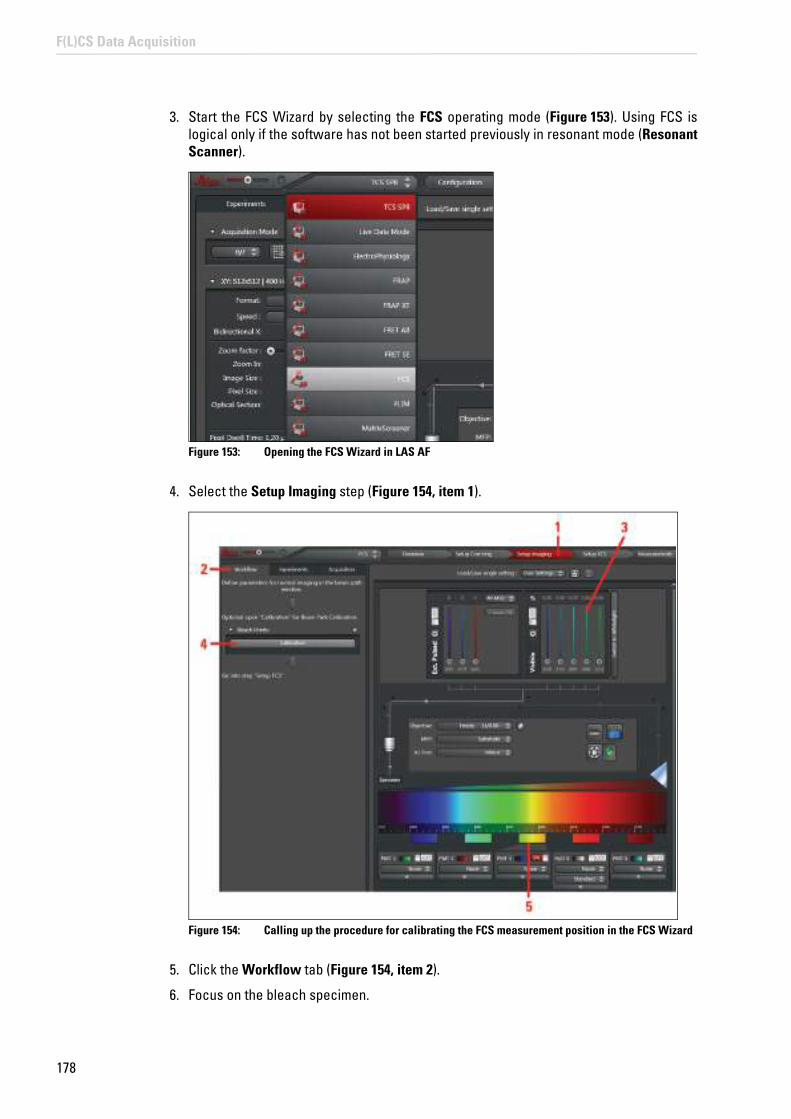
178
F(L)CS Data Acquisition
3. Start the FCS Wizard by selecting the FCS operating mode (Figure 153). Using FCS is logical only if the software has not been started previously in resonant mode (Resonant Scanner).
Figure 153: Opening the FCS Wizard in LAS AF
4. Select the Setup Imaging step (Figure 154, item 1).
Figure 154: Calling up the procedure for calibrating the FCS measurement position in the FCS Wizard
5. Click the Workflow tab (Figure 154, item 2).
6. Focus on the bleach specimen.

179
F(L)CS Data Acquisition
7. Select one (or more) suitable laser line(s) (Figure 154, item 3) and a suitable detection range on the detector (Figure 154, item 5),
8. Then specify the xyz mode and a scan speed of 400 Hz for an image.
9. Select Glow (O&U) in the color look-up table (LUT).
10. Click Calibration in the pull-down menu (Figure 154, item 4).
A window appears for the calibration procedure (Figure 155). The system automatically determines the following values: Zoom 32 and pixel format 1024x1024.
11. Start a continuous scan by clicking the Live button (Figure 155, item 1) and manipulate the Gain and Offset on the control panel to obtain a well-illuminated image.
Figure 155: Procedure for calibrating the FCS measurement position – Definition of instrument parameter settings
12. With Define bleach time, enter the bleaching period; The default value is 100 ms (Figure 155, item 2). For thin and easily bleached specimens, it may be more useful to select a bleaching period of 500 ms or shorter.
13. Now select the Calibrate button (Figure 155, item 3).
An image will be acquired automatically. Then, the previously selected laser lines will automatically be set to 100 % AOTF transmission for photobleaching, and the laser will bleach in the middle of the image for the set time. Then, another image will be acquired with the settings made previously.
14. Now position the crosshair in the middle of the bleach point (Figure 156, item 1) and

180
F(L)CS Data Acquisition
select the Set Calibration button (Figure 156, item 2).
Figure 156: Procedure for calibrating the FCS measurement position – Definition of the bleach point
The calibration data will be stored by the system and displayed under X and Y (Figure 157).
Figure 157: Display of the calibration data
Optimized calibration
The calibration is optimized primarily with regard to the scan speed defined during the calibration (default value: 400 Hz). The calibration applies for any zoom.

181
F(L)CS Data Acquisition
18.1.3 Testing the Positioning Accuracy
In order to test the positioning accuracy of the scanner on different pixels, the multipoint functionality for FCS can be used for a different purpose.
This test is not necessary to ensure the functional capability of the system as such; you use it only to confirm the performance capability of the system for yourself.
To carry out this test, proceed as follows:
1. Switch off all external detectors (the APD detector unit or the APDs with the DSN) electrically.
2. Start the SMD workstation.
3. Start the SymPhoTime software.
4. Create a new working area by selecting New Workspace in the File menu.
5. Using your bleach specimen, create a well-illuminated xy image as described in Chapter 18.1.2 in the Setup Imaging step of the FCS Wizard. Use the photomultipliers for this (Figure 154, item 5). Use the zoom that you want to test. Use the same scan speed as the one you used previously when calibrating the scanner.
6. Select the Measurements step in the FCS Wizard (Figure 158).
Observe the SymPhoTime manual
You will find information about creating a new working area in the SymPhoTime manual.

182
F(L)CS Data Acquisition
Figure 158: Testing the accuracy of the FCS measuring points – Setting the bleach points
7. Switch the APDs off electrically.
8. Select the initial bleach point in the xy image by clicking a point in the image display (Figure 158). Click the Add button (Figure 159, item 1).
Figure 159: Adding a bleach point and bleaching period
9. Select the next bleach point and click the Add button again. Continue until you have marked all the points you want.
10. Set the number of cycles to 1 by enabling the Image after each _ cycle check box in the

183
F(L)CS Data Acquisition
Setup tab and enter 1 (Figure 159, item 2). This will automatically take a new image after photobleaching all points.
11. Set the laser used for photobleaching to 100 %.
12. Under Measurement Duration, enter a suitable bleaching period; this will typically be a few seconds (Figure 159, item 3).
13. Start the bleaching series from LAS AF by clicking the image acquisition button Run FCS.
14. In the image acquired after photobleaching, compare the markings with the actual bleach points.
15. To archive your measurement, you can create a snapshot of the image with your bleach points. To do so, right-click this image and select Snapshot.
If the actual bleach points are not exactly what you want, repeat the calibration (Chapter 18.1.2).
18.1.4 Adjusting the Correction Ring on the Objective
To guarantee the correct form of the detection volume, the correction ring at the objective must be adjusted to the thickness of the specimen slide below the specimen. You must always make this adjustment when you change the specimen carrier, even if it comes from the same batch. You should also repeat this adjustment if the temperature changes. Follow these steps:
1. Start LAS AF.
2. Use the objective 63x Plan APO 1.2W CORR CS 0.14 to 0.18. Add immersion water to the objective and position the FCS specimen.
3. When you open the Setup Corr-ring step in the FCS Wizard, a preconfigured setting of the beam path is loaded. Adjust the settings as follows:
• Select scan mode xz-y (z-Galvo).
• Set the format to 512 x 512.
• Set the zoom to the smallest possible setting.
• Select the laser line at 488 nm.
• Use bidirectional scan.
• Set the AOBS to reflection.
• Enable a SP PMT (no HyD and no SP FLIM PMT).
• Adjust the detector range to detect the laser line as well.
• Select Glow (O&U) in the color look-up table (LUT).
4. Click the Live image acquisition button.
A live image of the reflection line is displayed, which you can now optimize.

184
F(L)CS Data Acquisition
Figure 160: Optimization of the correction ring in the Setup Corr-ring step
5. Move the focus using the z-drive of the microscope stand until you see the two reflection lines that appear between the immersion and the glass and between the glass and the specimen (Figure 161, only visible simultaneously at zoom 1).
Figure 161: Reflection at the transition between the cover slip and the immersion water (top) and between the cover slip and the specimen (bottom) on the inverted stand. The objective is optimized relative to the bottom reflection. (The top and bottom reflection are simultaneously visible only for zoom 1. However, this can be set only if the objective cap was previously disabled in LAS AF.)

185
F(L)CS Data Acquisition
6. Go to a higher zoom (e.g. 4 to 8) and activate a continuous xz scanning operation with the Live image acquisition button.
7. Rotate the correction ring into a position that provides the highest contrast in the reflection between the cover slip and the specimen (greatest possible intensity and symmetry, narrowest possible intensity maximum without secondary maximum values; Figure 162 and Figure 163).
Figure 162: Reflection between cover slip and measurement medium with poorly set position of the correction ring: The image is out of focus, several secondary peaks are visible
Figure 163: Reflection between cover slip and measurement medium with correctly set position of the correction ring: The image is sharp, and secondary peaks are scarcely visible
Reversed image with inverted microscope
Please note that with an inverted microscope the image is inverted. In this case, the bottom reflection (between glass and specimen) is the important signal that has to be optimized.

186
F(L)CS Data Acquisition
Repeat the correction ring adjustment whenever you insert a new FCS specimen.
18.1.5 Setting the Reference Position
When FCS measurements are taken in solutions, the measuring point must always be defined with the aid of a reference point. The reflection that is generated at the transition between cover slip and specimen serves as reference.
1. To do this, proceed as described in Chapter 18.1.4. Make sure that you obtain two reflections. On the inverted microscope, the upper reflection appears at the transition between the immersion and the cover slip; the lower reflection appears at the transition between the cover slip and specimen (Figure 161).
2. On the inverted microscope, place the reflection from the cover slip/specimen-transition approximately in the middle of the image.
3. Set the z-position to 0 on the stand.
Observe the user manuals for external lasers
Please refer to the information from the documents provided by the laser manufacturer for the external lasers. Pay particular attention to the laser manufacturer's notes!
4. Move the focus on the stand about 10-20 μm towards the specimen (positive numbers on the inverted stand). The reflection on the inverted stand should move towards the top edge of the image (Figure 164).
Figure 164: Selection of the FCS measurement position for measurements in solutions: The reflection between the cover slip and the solution must be above the middle of the image.
18.1.6 Acquiring a Reference Image
For measurements in cells or other structures, you will need an image of your specimen. You can acquire this image in any step of the FCS Wizard. However, you can change the settings for image acquisition only in the Setup Imaging step.

187
F(L)CS Data Acquisition
18.1.6.1 Image Acquisition Using Photomultipliers
Normally, reference images of sufficiently bright signals are acquired using the internal photomultipliers; this uses the high dynamic range of these detectors.
1. Switch the acousto-optical beam splitter (AOBS) to fluorescence (Figure 165).
Figure 165: Dialog for AOBS configuration
2. Search for a region of interest in the specimen.
3. You can create an image or stack in the Setup Imaging step of the FCS Wizard (Figure 166). Select suitable photomultipliers (Figure 166, item 2) and the laser (Figure 166, item 1). You can also use an xyz or xzy stack.

188
F(L)CS Data Acquisition
Figure 166: Settings for acquiring a reference image using photomultipliers
4. For a better comparison of the confocal image with the FCS measurement data, set the spectral detection window for image acquisition using the internal photomultipliers corresponding to the transmission of the SMD filter block used in the X1 port adapter. The laser lines and intensities for image acquisition may be the same as those for the FCS measurement, but they do not have to be.
5. Check that the external port X1 is switched to the Mirror position ( Figure 166, item 3).
6. Start a continuous scan by clicking the Live image acquisition button (Figure 166, item 4) and start an image acquisition by clicking the Capture Image image acquisition button (Figure 166, item 5).
18.1.6.2 Image Acquisition with PE APDs (AQR Type) or MPD APDs (PDM Type)
You can also acquire the image directly using the APDs. This procedure is recommended specifically for specimens with a low signal.
General recommendations for APD image acquisition:
• Slow scan speed (e.g. 10 to 100 Hz)
• Data accumulation (e.g. 4 to 8 frames)
• Best detection range for PE APDs: over 500 to approx. 800 nm, for MPD APDs: between 430 nm and 700 nm
• Adapt the scale of the color look-up table to the counting rate if necessary

189
F(L)CS Data Acquisition
1. First, switch on the APDs electrically.
2. Now activate the detectors APD1 and/or APD2 (Figure 167, item 1) in Beam Path Settingof LAS AF. Set the external port X1 to --- (Figure 167, item 2).
Figure 167: Settings for acquiring a reference image using APDs
3. If the audible warning signal for overload of the APDs sounds or the APDs shut off, reduce the illumination intensity immediately or switch off the APDs on the APD detector unit or on the DSN electrically. It is not sufficient to deactivate the APDs in Beam Path Settings.
4. Switch the MPD APDs back on manually. Activation of the MPD APDs takes about 20 seconds. The PE APDs switch on again automatically.
5. Start a continuous scan by clicking the image acquisition button Live (Figure 167, item 3) or start an individual image acquisition by clicking the image acquisition button Capture Image (Figure 167, item 4). Start with low laser intensity.
NOTICE Light that is too intense may damage the APDs
Never switch on the APDs under illumination. Otherwise, the detectors can be damaged irreparably.

190
F(L)CS Data Acquisition
18.2 Setup Imaging Step – Image Acquisition
1. Start the FCS Wizard in LAS AF. To do so, open the operating mode selector and select FCS.
2. For applications in cells or tissues, in the Setup Imaging step you first create an xy scan of your specimen in the desired z plane, or you acquire an xyz stack (with z-Galvo).
3. If you would like to display a 'z-section' of your specimen, you can also acquire an xz image or an xzy stack. This might be especially of interest when working on membranes.
Other imaging modes (like time series or lambda stack) are not supported. The image acquisition procedure is the same as the general procedure without using the FCS Wizard.
18.2.1 Selecting Detectors for the Image Acquisition
You can use photomultipliers as well as APDs for the image acquisition. Photomultipliers are distinguished by having wide dynamic range; APDs are distinguished by higher detection quantum efficiency. PE APDs are distinguished by very good red sensitivity.
18.2.1.1 Photomultiplier (PMT) / Internal Hybrid Detector (HyD)
1. Check that the external port X1 is switched to the Mirror position ( Figure 166, item 3).
2. In the beam path schema, activate the desired PMTs/HyD by clicking the appropriate check box.
3. Select the desired spectral range for detection.
4. Select low laser intensities.
5. You may also have to adapt the color look-up table (LUT). Click the color scale to call up the LUT selection dialog. There, you can select color look-up tables (LUT) for displaying the images to be acquired and create user-defined color look-up tables.
6. Optimize the image quality. The functions for this are the same as outside the wizard.
7. Acquire an image by clicking the Capture image acquisition button or acquire an xyz or xzy stack by clicking the Start image acquisition button. The start and finish of the stack are defined interactively, in the usual way. The stack image is automatically added to your LAS AF experiment.
18.2.1.2 PE / MPD APDs
1. First, switch on the APDs on the APD or DSN control unit electrically.
2. Set the external port X1 (X1 Port) to the position --- (Figure 168, item 1).
3. Deactivate all photomultipliers in Beam Path Settings.
4. Activate the APDs by clicking the corresponding check boxes (Figure 168, item 2).
5. Select low laser intensities.
6. You may also have to adapt the color look-up table (LUT). Click the color scale to call up the LUT Selection dialog. There, you can select color look-up tables (LUT) for displaying the images to be acquired and create user-defined color look-up tables. You can also configure the intensity setting via Gain and the control panel. This function

191
F(L)CS Data Acquisition
has no effect on the detector; it modifies the color look-up table, which renders low-intensity structures more visible. It may also be helpful to accumulate over several images. The Offset setting on the control panel has no effect on the image.
Figure 168: Acquiring the reference image using APDs, setting the X1 port
7. Optimize the image quality. The functions for this are the same as outside the wizard.
8. Acquire an image by clicking the Capture image acquisition button or acquire an xyz or xzy stack by clicking the Start image acquisition button. The start and finish of the stack are defined interactively, in the usual way. The stack image is automatically added to your LAS AF experiment.
18.2.2 Selecting Laser Lines as an Excitation Source for the Image Acquisition
All available lasers can be used for the image acquisition (Figure 169). You will find a description of the mode of operation in Chapter 15.
18.2.2.1 Using Continuous Wave Lasers
For capturing the emitted fluorescence, set the acousto-optical beam splitter to fluorescence (Figure 169). Choose a suitable laser line and adjust the intensity to the desired level using the AOTF slider. If the system has a multifunction port (MFP), it should be set to Substrate.
Dependency of the spectral detection range of the APDs
The spectral detection range of the APDs is determined by the SMD filter cube used, not by the slider settings for the photomultipliers.

192
F(L)CS Data Acquisition
Figure 169: Acquiring the reference image using continuous wave lasers and photomultipliers
18.2.2.2 Using MP Lasers
1. For MP scanning operations, select the desired wavelength.
2. Choose a suitable neutral density filter for the attenuation using the Trans slider and/or adjust the electro-optical modulator (EOM) using the Gain and Offset sliders.
3. If the system has a multifunction port, it should be set to SP680 or SP700.
For more detailed information about switching on the MP lasers, refer to Chapter 15.1.2.
18.2.2.3 Using Pulsed VIS Lasers
1. Close the shutter of the continuous wave VIS laser in Beam Path Settings and move all acousto-optical tunable filters to the 0 position.
2. Open the shutter for pulsed lasers (Figure 170, item 1).
3. Activate the desired laser by moving the corresponding slider upwards (Figure 170, item 2).

193
F(L)CS Data Acquisition
Figure 170: Settings for using pulsed VIS lasers as excitation source
4. Check whether the correct beam splitter (MFP) is selected (Table 18, page 123).
5. You can use the pulsed VIS lasers together with the pulsed UV laser (405 nm). The MFP setting is not influenced by UV. It is defined by the selection of the pulsed VIS lasers.
18.2.2.4 Using a Pulsed UV Laser
1. Open the shutter for pulsed lasers.
2. Activate the 405-nm laser by moving the corresponding slider.
3. If no other pulsed laser is used, you can set the multifunction port (MFP) to Substrate.
Controlling laser intensity of the pulsed laser
For pulsed lasers, the slider does not affect the laser intensity. Laser intensity needs to be controlled at the desired laser.
Combination pulsed and continuous wave VIS excitation
Do not use any pulsed VIS excitation together with continuous wave VIS excitation for continuous wave laser lines close to the wavelengths of the pulsed laser (such as the combination 470 nm pulsed + 488 nm continuous wave), as no optimum MFP setting exists for such a combination.

194
F(L)CS Data Acquisition
For more detailed information about using the pulsed UV laser, refer to Chapter 15.1.4.
18.2.2.5 Using White Light Lasers
1. Select the desired laser lines in the Whitelight dialog in Beam Path Settings.
2. Make sure that the AOBS is at fluorescence.
3. Set the desired intensity using the AOTF slider.
4. If the system has a multifunction port (MFP), it should be set to Substrate.
5. Open the Acquisition tab and adjust the rotation to 0° using the slider (Figure 171, item 1).
Figure 171: Adjusting the diameter of the pinhole and rotation
18.2.3 Adjusting the Pinhole for Image Acquisition
For VIS and UV excitation, set the Pinhole diameter to 1 Airy; for MP excitation set it to the maximum size (Figure 171, item 2).
Positioning the multifunction port
Within the FCS Wizard, positioning of the multifunction port is automated; outside the wizard, it must be set by the user. The automatic configuration can be changed subsequently by the user.

195
F(L)CS Data Acquisition
18.3 Setup FCS Step – Optimizing FCS Measurement Conditions
1. Open the Setup FCS step in the FCS Wizard.
2. Now set the instrument parameters for an FCS measurement.
18.3.1 Selecting APDs
The APDs are external detectors. For FCS, they do not have to be activated specially in the software.
1. Switch the APDs on electrically.
2. If you do not receive a signal after starting a test measurement, check that the external port (X1 Port) is set to ---.
Activation/deactivation of individual detectors in Beam Path Settings and settings for the spectral sliders for the photomultipliers are not relevant for the FCS measurement.
18.3.2 Selecting Laser Lines for FCS
Typically, FCS measurements are carried out using continuous wave VIS laser lines. UV laser lines are not specified and are also not recommended due to the reduced quantum efficiency of the APDs in the blue spectrum.
Furthermore, MP excitation is not specified for FCS. Pulsed visible lasers (diode lasers, white light lasers) can be used for time-resolved FCS measurements, like FLCS or gated FCS.
18.3.2.1 Using Continuous Wave VIS Lasers
1. Choose a suitable laser line and laser intensity by setting the AOTF slider.
2. The acousto-optical beam splitter must be set to fluorescence.
3. In front of the argon laser, there is an FCS filter wheel for additional clean up of selected laser lines and for further attenuation. When selecting a laser line by the AOTF setting, the FCS filter wheel is automatically moved to the right position. You can check the position in the pull-down menu from Filter Wheel in Beam Path Settings (Figure 172). Other laser lines are not affected by the FCS filter wheel.
Do not change Acquisition mode any more
Do not make any more changes to the Acquisition mode (xyz or xz) used in the last image. The positioning of the FCS point must be set in the same mode as the most recently acquired image.

196
F(L)CS Data Acquisition
Figure 172: Controlling the FCS filter wheel
Due to the configuration of the FCS filter wheel, the following laser lines are not available for FCS and are therefore grayed out in the software (Figure 172):
• 476 nm
• 496 nm
The following combinations are also not possible (although the individual lines can be used on their own):
• 458 nm with 488 nm
• 488 nm with 514 nm
The combination of 458 with 514 nm can be used, however.
The FCS filter wheel is used only in the Setup FCS and Measurements steps of the FCS Wizard. In all other cases it is in an empty position. This means that all argon laser lines used in the FCS measurement (Setup FCS and Measurements steps in the FCS Wizard) are attenuated for the image acquisition relative to the normal mode: The 458-nm line is attenuated by 25 percent, the 488-nm line by 75 percent, the 514-nm line by 75 percent, and the combination of 458 and 514-nm lines by 50 percent. The other lasers are not affected by attenuation.
18.3.2.2 Using Pulsed VIS Diode Lasers
For FCS, the pulsed diode lasers can be used in the VIS range. The observation volume and therefore the diffusion time are greater than when using the continuous wave lasers.
For what comes next, follow the instructions in Chapter 18.2.2.

197
F(L)CS Data Acquisition
18.3.2.3 Using White Light Lasers
The white light laser can be used for FCS. The signal-noise ratio is optimized when you select laser lines that are available in the fluorifier disc and position the filter wheel accordingly (Chapter 16.2.3). If you want to adjust other laser lines, the distance between displayed laser wavelength and detection range (FWHM) should be >12 nm.
Unlike FLIM and FLCS, with FCCS you can also use two white light laser excitation lines. For systems with a pulse picker, we recommend operating the laser for FSC and FCCS measurements at the maximum frequency (80 MHz). For FLCS, the recommended frequency is 40 MHz.
Figure 173: Setting of an FCCS measurement with the white light laser as excitation source
18.3.3 Fluorifier Disc
Most SMD FCS systems have a fluorifier disc. If there is such a fluorifier disc, select a barrier filter as described in Chapter 16.2.3. You can open the Fluorifier Disc dialog in Beam Path Settings.
Figure 174: Fluorifier Disc button in Beam Path Settings
18.3.4 Setting the Pinhole
Set the Pinhole diameter in the Setup tab to 1 Airy.

198
F(L)CS Data Acquisition
18.3.5 Optimizing FCS Settings
1. First, use the image display to find a measuring point in the image. Move the crosshair in the image display to the desired position (Figure 175).
Figure 175: Selecting the measuring points
2. Press the Run FCS Test button (Figure 176, item 1) on the Setup tab to start the illumination. You can view and optimize the fluorescence intensity in the count rate monitor. Laser line and intensity can be modified during the test measurement until you attain the count rate or counts per molecule desired.
3. The scanner cannot be moved out of its defined position while Run FCS Test is still active. To move the scanner to another position, you first have to stop the FCS measurement by clicking the Stop FCS Test button.
4. Then, move the crosshair to the desired position and restart the measurement by clicking the Run FCS Test button.
When you start the test measurement, an online correlation curve is displayed in SymPhoTime.
A scanning operation is required before an FCS measurement
After starting LAS AF, at least one scanning operation has to be carried out (using Live or Capture) before an FCS measurement can be started. This is also necessary when working in solutions only. Otherwise, no FCS measurement is started.

199
F(L)CS Data Acquisition
Figure 176: Starting the FCS test and applying the measuring point
5. To end illumination of the specimen, click the Stop FCS Test button in LAS AF. This will also stop the online correlation display in SymPhoTime.
6. If you would like to reuse a tested FCS measuring point later for the 'correct' FCS measurement, click Add Point (Figure 176, item 2) in the Setup tab. This measuring point is then written to a position list, which is used in the Measurements step in LAS AF. Do not make any more changes to the zoom. Changing the zoom in the Setup FCS step would render the position list invalid.
The instrument parameters set for the FCS measurements (laser lines and associated intensity, pinhole, AOBS) are kept as separate FCS settings that are independent from the image acquisition setting defined in the Setup Imaging step. The FCS settings defined in the Setup FCS step are automatically transferred to the Measurements step.
18.3.6 Count Rate Monitor
The count rate of each channel is displayed in the Setup tab. For FCS, the count rate should be between 10,000 and 500,000 cps (counts per second).
If the two detection channels are reversed, change the allocation in SymPhoTime. The allocation of the channels is preset and should not be changed.
• FCS Channel A: Check box 1
• FCS Channel B: Check box 2
Saving the data in Measurements
This curve is not saved. If you want to save your data, you have to work in the Measurements step.
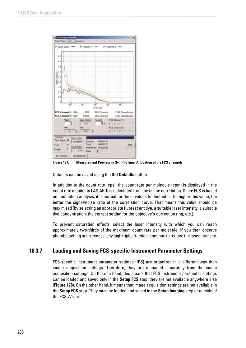
200
F(L)CS Data Acquisition
Figure 177: Measurement Preview in SymPhoTime: Allocation of the FCS channels
Defaults can be saved using the Set Defaults button.
In addition to the count rate (cps), the count rate per molecule (cpm) is displayed in the count rate monitor in LAS AF. It is calculated from the online correlation. Since FCS is based on fluctuation analysis, it is normal for these values to fluctuate. The higher this value, the better the signal/noise ratio of the correlation curve. That means this value should be maximized (by selecting an appropriate fluorescent dye, a suitable laser intensity, a suitable dye concentration, the correct setting for the objective's correction ring, etc.).
To prevent saturation effects, select the laser intensity with which you can reach approximately two-thirds of the maximum count rate per molecule. If you then observe photobleaching or an excessively high triplet fraction, continue to reduce the laser intensity.
18.3.7 Loading and Saving FCS-specific Instrument Parameter Settings
FCS-specific instrument parameter settings (IPS) are organized in a different way than image acquisition settings. Therefore, they are managed separately from the image acquisition settings. On the one hand, this means that FCS instrument parameter settings can be loaded and saved only in the Setup FCS step; they are not available anywhere else (Figure 178). On the other hand, it means that image acquisition settings are not available in the Setup FCS step. They must be loaded and saved in the Setup Imaging step or outside of the FCS Wizard.

201
F(L)CS Data Acquisition
Figure 178: Loading and saving FCS-specific instrument parameter settings
18.4 Measurements Step – FCS Measurement Time Series at Multiple Points
After optimizing the FCS measurement conditions, it is possible to have FCS measurements run automatically at previously defined measuring points with the previously defined settings. To do so, go to the Measurements step.
18.4.1 FCS Network Connection
The LAS AF and SymPhoTime programs are synchronized via a network connection. Each FCS measurement started in LAS AF in the Measurements step of the FCS Wizard generates a new data file in SymPhoTime. In addition to the synchronization, the network also enables transmission of relevant information such as the file name, instrument parameter settings (IPS), or comments entered by the user in LAS AF.
During the FCS measurement, an online correlation curve is displayed that is automatically saved along with the raw data in SymPhoTime. After the data acquisition, a more detailed data analysis can then be carried out offline.
Do not change Acquisition mode any more
Do not make any more changes to the Acquisition mode used to acquire the last image.
Observe the SymPhoTime manual
For more detailed information about data analysis, refer to the SymPhoTime manual.

202
F(L)CS Data Acquisition
18.4.2 Definition of Multiple FCS Measuring Points in an Image or Stack
Figure 179: Overview of the Measurements step in the FCS Wizard

203
F(L)CS Data Acquisition
Figure 180: Setting of multiple FCS measuring points in a previously acquired xyz image stack
To set the FCS measuring points for FCS measurement time series, proceed as follows:
1. Take an xy or xz image or take an xyz or xzy stack.
2. Select the instrument parameter setting for the FCS measurement in the Setup FCS step.
3. Move to the Measurements step in the FCS Wizard. If necessary, you can fine-tune the laser intensity here (Figure 179).
4. In the Experiments tab, check that the current image or xyz or xzy stack has been activated.
5. Select the first measuring point in the image or stack in the image display.
6. Click Add (Figure 179).
7. To document the measuring point, right-click in the image and then click Snapshot.
204
F(L)CS Data Acquisition
8. Select the next measuring point, click Add, and create another snapshot as necessary.
9. Continue until you have marked all the points you want. The maximum number of points is 200.
10. Different measuring points in an xyz or xzy stack can be located on different z or y planes, respectively. Select the z or y planes you want in the image display. Place the crosshair on the xy point you want in the desired z plane or xz point on a certain y position.
11. Then click Add (Figure 179).
12. After this, a position list is created that can be saved by selecting Save list and called up at a later time (Figure 179). Individual points can be deleted from the list with Remove, and the entire list can be deleted with Remove all (Figure 179).
13. Enter a measurement time in the LAS AF software, that is, the time required for a single measurement (Figure 179).
14. The selected measurement duration and the instrument parameter setting for the FCS measurement are applied to all individual measuring points.
15. If you are working in xyz mode, you can still change the zoom within the Measurementsstep.
18.4.3 FCS Time Series at Multiple Measuring Points
In the Setup tab, it is possible to define a time series in two ways:
• Repeated measurements at single points (definition in the Definition of Point Measurement field)
• Repeated processing of all points (definition in the Time Series field).
By combining both kinds of definition, a time series can be created within a time series.
For repeated measurement at individual points, the following functions are available:
• Pre-bleach: Enables you to define a time in which the laser is switched on before the measurement begins. This feature can be used to pre-bleach the specimen before the measurement (Figure 181, item 1).
• Measurement duration: Specifies the duration of an individual FCS measurement (Figure 181, item 2). The minimum measurement duration is 1 second; the maximum measurement duration is 10 minutes.
• Repetition at point: The entered number specifies how often the measurement at this point is repeated before the system moves on to the next point (Figure 181, item 3). The maximum number of repetitions is 1000.
• Repetition interval: Specifies the time between the beginning of one measurement and the following measurement at this point. The value cannot be smaller than the sum of measurement and pre-bleach time (Figure 181, item 4).
• Minimize: If the Minimize box is checked, repetitions will be carried out as fast as possible (Figure 181, item 5).
Do not leave the Measurements step until FCS data acquisition
You may no longer leave the Measurements step until the FCS data acquisition, otherwise the position list becomes invalid.

205
F(L)CS Data Acquisition
• Number of defined points: The user does not have access to this field. It serves to visualize the number of measuring points defined in the viewer (Figure 181, item 6).
The maximum number of FCS measurements in a measurement series is 1000.
Figure 181: Definition of an FCS Time Series
The following functions are available for repeated processing of all points:
• Number of cycles: A Cycle means that, in the sequence of their definition, the individual measuring points are processed exactly once in the image display with the number of repetitions specified in the Definition of point measurements dialog. The input field enables you to specify the repetitions to be carried out relative to a complete cycle (Figure 181, item 7). The maximum number of cycles is 1000.
• Cycle interval: Specifies the time between the beginning of one cycle and the next cycle (Figure 181, item 8). If the Minimize box is checked, processing cycles will be carried out as fast as possible (Figure 181, item 9).
• Image after each __ cycles: If you enable check boxes and enter the number 1, an image or stack is acquired with the current image acquisition settings after each cycle. If you enter the number 2, an image or stack is acquired after every second cycle; if you enter 3, after every third cycle, and so on. After processing all cycles, one last image or stack will be acquired (Figure 181, item 10).

206
F(L)CS Data Acquisition
• The user does not have access to the Total number of measurements field. It serves to visualize the number of FCS measurements carried out (Figure 181, item 11). This number is the product of Number of defined points times Repetition at point times Number of cycles.
The maximum number of FCS measurements in a measurement series is 1000.
Start the measurement series in LAS AF by clicking the Run FCS image acquisition button.
18.4.4 Definition of the File Names Transferred to SymPhoTime during the FCS Measurement
You can specify the name of the FCS data file used in SymPhoTime in the Setup tab in the Definition of point measurement field (Figure 181, item 12).
The following functions are available:
• Whenever a series of FCS measurements is started, SymPhoTime generates a folder that houses all FCS measurement files of this series. The name of the folder is composed as follows:
• BaseName_Run Base name: Enables you to specify the base folder and file name used in SymPhoTime (Figure 181, item 12). If the user does not enter a name, BaseName will be automatically used. Run: This is a suffix that is added to the file names transferred in SymPhoTime. In SymPhoTime, no two folders may have the same name. Therefore, the number given in the Run suffix is automatically increased by one whenever a measurement series is started. The Run suffix can be changed by the user (Figure 181, item 13).
• The file name uses the same BaseName and Run components as the folder. Additionally, LAS AF will automatically add some more suffixes to the file name that contain the following information:
• Cycle
• Measuring point
• Repetitions at this point
The file name structure is as follows:
• BaseName_Run_Cycle_Measuring point_Repetition
• The Measuring point number is identical to the number used in the image display.
These additional suffixes cannot be modified by the user.
• If Image after each __ cycles is enabled, an image or stack is automatically saved in LAS AF with the following name: BaseName_Run_Cycle
Do not use the same name
Do not enter the same BaseName_Run name twice. This will create an error message.

207
F(L)CS Data Acquisition
This makes it easier to allocate the images in LAS AF to the corresponding FCS data in SymPhoTime.
18.4.5 FCS z-Stack
An FCS z-stack can be particularly useful for FCS measurements on membranes. To create an FCS z-stack, follow these steps:
1. First acquire an xyz stack in the Setup Imaging step in the FCS Wizard (Chapter 18.2).
2. If necessary, optimize the measurement conditions in the Setup FCS step (Chapter 18.3).
3. Change to the Measurements step.
4. Use the image display to find the xy point in the z image stack at which you want to generate the FCS z-stack.
5. In the z image stack, go to the top z plane that is of interest to you. Click on the desired xy position and then on Add in Beam Path Settings (Figure 179). Go to the plane below; do not change the xy position, but click Add. Then go to the plane below that, etc. Continue until you reach the lowest plane that is of interest to you. If you wish, you can also acquire the z FCS stack from the bottom upwards.
6. Define the measurement duration, the number of repetitions at each point, and the number of cycles as described in Chapter 18.4.3. The FCS instrument parameter settings are identical at all measuring points.
7. Specify folder and file names as described in Chapter 18.4.4.
8. Click the Run FCS image acquisition button in LAS AF.
The maximum number of FCS measurements in a measurement series is 10,000.

208
F(L)CS Data Acquisition
18.4.6 Operating the FCS Measurement Series
The measurement series is started by clicking Run FCS image acquisition button. It stops automatically after all measurements are taken. A user-defined stop is possible by clicking Stop FCS (Figure 179).
In the count rate monitor (Figure 179), the current count rate (in cps – counts per second) of each channel as well as the counts per molecule (in cpm – counts per second per molecule) are displayed during the individual measurements.
In SymPhoTime, an online correlation curve is displayed and saved together with the raw data.
Both the count rate and correlation curve give a first impression about the quality of the measurements. Images acquired automatically during the FCS measurement series (with Image after each __ cycles, Figure 181) can indicate movements of the specimen.

209
Summarized manual for FCS or other point measurements
19 Summarized manual for FCS or other point measurements
19.1 Prerequisites
The following description assumes that the following prerequisites are met:
• SymPhoTime is started and a workspace is loaded.
• LAS AF was started.
• The right objective has been chosen and the correction ring adjusted to the specimen used (Chapter 18.1.1 and Chapter 18.1.4).
• Your specimen is already placed onto the microscope and brought into focus. If you are measuring in solution, it is assumed that the laser is focused into the solution (see Chapter 18.1.5).
• The selected excitation lasers are switched on and activated (Chapter 18.2.2 and Chapter 18.3.2).
• The correct emission filter(s) has/have been placed in your detector unit (Chapter 23).
• For beam splitter systems: The correct beam splitter for your wavelength has been selected in LAS AF.
• With AOBS systems: The acousto-optical beam splitter is in fluorescence mode.
19.1.1 Choosing the Location for the FCS Measurement
1. Start the FCS Wizard in LAS AF.
2. Scan an image. Also use the Setup Imaging step in the FCS Wizard.
3. Select the position at which you want to run a point measurement (Chapter 18.2).
4. Start the FCS test mode in LAS AF by selecting the image acquisition button Run FCS Testunder the Setup FCS step in the FCS Wizard (Chapter 18.3). Normally, the SymPhoTime software will start the data acquisition automatically. However, you can also start the FCS data acquisition by selecting the Acquire Point Measurements button in the SymPhoTime software.
The Measurement Preview dialog in SymPhoTime opens on the FCS tab (Figure 182, left).
5. The display of the cross-trace and the two autocorrelation traces can be selected using the check boxes above the trace.
6. The update time can be set in the Refresh field. Together with the average count rate, the G(0) value and the molecular brightness (Counts/Molec.) are shown for the individual channels.
The molecular brightness is calculated by G(0) times the average count rate and displays the mean fluorescence count rate per dye molecule. The system is optimized (for example by adjusting the laser intensity and the objective collar) when maximum molecular brightness is attained. In the Time Trace tab (Figure 182, right) the changes of the count rate over time can be observed. The binning (resolution) should be set to 1 ms.

210
Summarized manual for FCS or other point measurements
7. The settings in the Measurement Preview window in SymPhoTime can be preset by selecting Show Measurement Preview... when no measurement is running. Defaults can be saved using the Set Defaults button.
8. The number of calculated points per trace can be adjusted with NSub. The channel assignment is already preset, as shown in Figure 182. You should not change this assignment.
Figure 182: Online monitoring of the FCS trace and photon count rate in the SymPhoTime preview window. Left: FCS traces after 60 seconds of acquisition, cross and autocorrelation. G(0) near one corresponds to an average number of one dye molecule in the confocal detection volume. Right: Display of the count rate over time. The fluorescence bursts of single molecules are clearly visible.
19.2 Starting Point/ FCS Data Acquisition
1. Start the FCS Wizard in LAS AF.
2. Scan an image according to the Setup Imaging step (Chapter 18.2).
3. Optimize the FCS settings in step Setup FCS (Chapter 18.3 and Chapter 19.1.1).
4. Go to the Measurements step (Chapter 18.4).
5. Select the positions where you want to carry out a point measurement.
'Fifo overrun' error message
At very high count rates, depending on the computer power and number of calculated points per FCS trace, a Fifo overrun error can occur. In this case, use low Nsub values or switch off the FCS online correlation by unchecking the FCS check box under Previews.

211
Summarized manual for FCS or other point measurements
6. Select the measurement times.
7. Start the FCS measurement in LAS AF by selecting the image acquisition button Run FCSunder the step Measurements. Normally, the SymPhoTime software will start the data acquisition automatically. If you start the FCS data acquisition by selecting Acquire Point Measurements in the SymPhoTime software, the measurement is not synchronized with LAS AF. The file name, comments and instrument parameter settings are not transferred from LAS AF to SymPhoTime.
8. The Measurement Preview dialog opens in SymPhoTime on the FCS tab (Figure 182, left). The FCS curve is integrated over time.
Figure 183: Working area of the annotation file
9. At the end of the measurement, the result can be viewed in the annotation file which can be opened from the workspace (Figure 183). Open the Correlation tab as shown in Figure 184. The curves can be analyzed by selecting the FIT button that corresponds to the cross-correlation or autocorrelation curve.
10. Starting from the acquired raw data file (in this case, FCS 01.pt3), the FCS curve can be recalculated with enhanced functions, such as Time Gated FCS or Fluorescence Lifetime Correlation Spectroscopy (FLCS) using the FCS trace button. The prerequisite for both of these modes is that the FCS measurement was carried out using pulsed lasers for excitation.

212
Summarized manual for FCS or other point measurements
Figure 184: Display of the FCS curves in the "Correlation" tab of the annotation file
Using detectors with high quantum efficiency
FCS measurements can only be carried out with detectors with high quantum efficiency, such as APDs. Using cross-correlation between two detectors, detector after pulsing effects can be suppressed all the way to the correlation curve. With pulsed excitation, alternatively, FLCS can be used to calculate detector after-pulses for the individual detection channels from the raw data.
A stable count rate for FCS analysis is necessary
For a reliable FCS analysis, the count rate has to be stable. Signal attenuation due to photobleaching may lead to an increasing FCS correlation amplitude at long lag times.

213
Changing the Specimen
20 Changing the Specimen
WARNING Risk of permanent eye damage from laser radiation
Never change specimens during the scanning operation because laser radiation can escape uncontrolled from the specimen area.
20.1 Changing the Specimen on an Upright Microscope
To change specimens on an upright microscope, proceed as follows:
1. Finish the scanning operation.
2. Ensure that no laser radiation exists in the specimen area.
3. Replace the specimen. Insert the specimen correctly into the specimen holder.
4. If you carry out FCS measurements, you have to reset the correction ring of the objective after every specimen change.
20.2 Changing the Specimen on an Inverted Microscope
To change specimens on an inverted microscope, proceed as follows:
1. Finish the scanning operation.
2. Ensure that no laser radiation exists in the specimen area.
3. Tilt the transmitted light arm back.
4. Replace the specimen. Insert the specimen correctly into the specimen holder.
5. Tilt the transmitted light arm back into the working position.
6. If you carry out FCS measurements, you have to reset the correction ring of the objective after every specimen change.

214
Changing the Specimen
215
Changing the Objective
21 Changing the Objective
WARNING Risk of permanent eye and skin damage from laser radiation
Never change objectives during the scanning operation because laser radiation can escape uncontrolled from the specimen area.
To change objectives proceed as follows:
1. Finish the scanning operation.
2. Switch off the internal lasers using the detachable-key switch.
3. If any external lasers are present, switch them off with their detachable-key switch or as described in the laser manufacturer's user manual.
4. Rotate the objective nosepiece so that the objective to be changed is swiveled out of the beam path and points outward.
5. Exchange the objective.
6. Close all unoccupied positions in the objective nosepiece using the supplied caps. System operation with unlocked positions in the objective nosepiece is not allowed.
WARNING Risk of permanent eye and skin damage from laser radiation
All non-occupied positions in the objective nosepiece must beclosed with the caps provided in order to prevent the uncontrolled escape of laser radiation in the specimen area.

216
Changing the Objective

217
Piezo Focus on an Upright Microscope
22 Piezo Focus on Upright Microscope
If there is a piezo focus installed on your system (see Figure 185) pay careful attention to the following notes:
• Make sure that the specimen carrier is not against the objective and cannot be damaged by it or cause broken glass. The objective could likewise be damaged.
• Before switching the system on or launching the LAS AF software, ensure that there is no slide or specimen on the stage and that the specimen stage is in its lowest possible position. If this is not observed, specimens and objectives can be damaged or destroyed upon system/software startup by the initialization of the piezo focus.
• Do not carry out the objective change automatically. The automatic motion may damage the cable of the piezo focus.
• Do not make any adjustments to the piezo focus controller (see Figure 186), as it has already been optimally set up by Leica Service.
• When replacing the objective on the piezo focus, you must perform a teach-in for the new objective in LAS. Please see the instructions on this topic in the microscope operating manual.
• Please note that the focus position of an objective with piezo focus is 13 mm lower than those without piezo focus. In order to guarantee the same focal plane, a spacer is installed on all other objectives (see Figure 187).
Figure 185: Piezo focus on objective nosepiece
The objective can be moved by 150 μm in either direction. The total travel is 300 μm.
Piezo focus controller display:
• Highest position: 350 μm
• Middle position: 200 μm
• Lowest position: 50 μm
• xz scan range: 250 μm

218
Piezo Focus on an Upright Microscope
Figure 186: Piezo focus controller
Figure 187: Spacer on objective

219
Changing the Filter Cube
23 Changing the Filter Cube
SMD filter cubes for the following dye combinations are available for the Leica SMD system:
Table 22: List of available SMD filter cubes
WARNING Risk of permanent eye damage from laser radiation
Never change filter cubes during the scanning operation because laser radiation can escape uncontrolled from the specimen area.
Dye combination
Maximum number of external
detection channels
Possible excitation lines
Beam splitter
Bandpass I
Bandpass II
neutral 2 50/50 % - -
Polarization 2 Polarization - -
GFP wide / RFP 2 458, 470, 488, 561, 594
LP 560 500 – 550 607 – 683
Alexa 488 / Alexa 633
2 458, 470, 488, 561, 594, 633
LP 620 500 – 550 647 – 703
CFP / YFP 2 405, 458, 514 LP 505 467 – 499 535 – 585
CFP/RFP 2 405, 458, 561, 594 LP 560 470 – 550 607 – 683
GFP narrow / RFP
2 458, 470, 488, 543, 561, 594
LP 560 500 – 530 607 – 683
GFP / RFP 2 458, 470, 488, 561, 594
LP 560 500 – 550 607 – 683
FITC/TRITC 2 458, 470, 488, 543 LP 560 500 – 550 565 – 605
GFP/HcRed 2 458, 470, 488, 561 LP 560 500 – 550 581 – 654
Alexa 405/ cy2 2 405, 470, 488 LP 470 418 – 458 500-550
DAPI, Atto 647 2 405, 514, 543, 561, 594, 633, 640
LP 620 420 – 500 650-710
Cy2/Cy5 2 470, 561, 633, 640 LP 620 485 – 550 650-710
CFP 440/YFP 2 405, 440, 514 LP 505 465-500 535-585
CFP 440/HcRed 2 405, 440, 514, 543, 561
LP 560 465-500 581-654
empty 1 - - -
VIS 1 405 - - LP 430
DAPI 1 405 - - 420 - 500
FITC 1 405, 470, 488 - - 500 - 550
TRITC 1 514, 543 - - 565 - 605
Cy5 1 562, 594, 633 - - 650 - 710

220
Changing the Filter Cube
Because the locking screws are accessible from the outside, the filter cubes can be replaced without removing the housing.
1. Abort the scanning operation.
2. Turn the key switch on the supply unit into the "OFF" position.
3. Switch off the APDs.
4. Detach the screws:
Figure 188: Adaptation at X1 port with SMD filter cube
5. Replace the filter cubes.
6. Retighten the locking screws.
7. Switch the APDs back on. It takes about 15 seconds until these are ready to operate. Do not carry out any scanning operation during that time.
Correct orientation and exact positioning of the filter cubes are assured by a locating pin arrangement of the retainer.

221
Changing Detector Connections on the Scan Head and Router When Using HyD-RLD
24 Changing Detector Cable Connections on the Scan Head and Router When Using HyD-RLD
If you have a Leica TCS SP8 SMD with MP configuration and external MPD APDs, internal SP FLIM PMT and HyD-RLDs, you can use the different detectors for different SMD experiments.
Limitations when using HyD-RLDs
When using external MPD APDs and HyD-RLDs, there are two signals that are transferred over different cables: the image signal and the SMD signal. The SMD signal cable has to be connected with the PHR 800 router and the image signal cable with the connection of the APD printed circuit board on the scan head. When using multiple detectors, it is necessary that the detectors used are connected correctly with the PHR 800 router and the scan head's APD printed circuit board. For this purpose, changing the cable is necessary.
The following detectors can be used and have to be connected correspondingly:
• SP FLIM PMT: The SMD signal cables have to be connected with CH 1 IN and CH 2 IN at the router's CFD input.
• MPD APD (SPAD 1 and SPAD 2): The image signal cable has to be connected at the APD printed circuit board of the scan head and the SMD signal cable has to be connected to CH 1 (detector channel 1) and CH 2 (detector channel 2) of the router.
• HyD-RLD: The image signal cable has to be connected at the APD printed circuit board of the scan head and the SMD signal cable has to be connected to CH 1 IN and CH 2 IN at the router's CFD input.
The following lasers can be used and have to be synchronized with the Pico Harp 300 counting unit:
• MP (infrared laser): The MP synchronization cable has to be connected to CH 0 of the counting unit.
• White light laser The white light laser synchronization cable has to be connected to the counting unit's CH 0.
• Argon laser (if present): The argon laser has no synchronization cable, therefore the MP or white light laser synchronization cable can remain connected with CH 0 of the counting unit.
• APDs for FLCS and HyD-RLDs cannot be used simultaneously for confocal image acquisition
• SP FLIM PMTs and HyD-RLDs cannot be used simultaneously for FLIM experiments.
NOTICE Damage to the instrument when changing the cable connections is
Switch all electronic components off before changing the cable connection, as otherwise the detectors or the scan head could become damaged. Also switch off the LAS AF, the scan head and the detectors.

222
Changing Detector Connections on the Scan Head and Router When Using HyD-RLD
Figure 189: Overview of the terminals and cable connections
24.1 Hardware Trees
In order to enable all applications, your system is delivered with three different hardware trees: two for use of APDs and a third for use of HyD-RLDs. Select the correct hardware tree for the desired application when starting LAS AF:
• MP on FCS FLIM 2 APD (with use of SP-FLIM-PMTs and external APDs)
• MP off FCS FLIM 2 APD (with use of SP-FLIM-PMTs and external APDs)
• MP on HyD RLD FLIM (with use of HyD-RLD)
Depending on the hardware tree selected, various lasers and detectors are available to you which can be used for different applications. On the following page, you will find an overview of which applications are possible with the respective hardware configurations. The connections which must be created by the detector and the laser are on Page 221.

223
Changing Detector Connections on the Scan Head and Router When Using HyD-RLD
24.1.1 MP on FCS FLIM 2 APD
24.1.2 MP off FCS FLIM 2 APD
24.1.3 MP on HyD RLD FLIM
SP FLIM PMT MPD APD HyD-RLD (no connection)
MP laser Image acquisition, Descanned spectral MP FLIM
Image acquisition, Descanned MP FLIM
not possible
White light laser Image acquisition, Spectral WLL FLIM
Image acquisition, WLL FLIM, WLL FCS, WLL FLCS
not possible
Argon laser (if present)
Image acquisition Image acquisition,Continuous wave FCS
not possible
SP FLIM PMT MPD APD HyD-RLD (no connection)
White light laser Image acquisition, Spectral WLL FLIM
Image acquisition, WLL FLIM, WLL FCS, WLL FLCS
not possible
Argon laser (if present)
Image acquisition Image acquisitionContinuous wave FCS
not possible
SP FLIM PMT MPD APD (no connection between APDs and APD printed circuit board on the scan head)
HyD RLD
MP laser Image acquisition, no FLIM (SMD signal cable is not connected)
Descanned MP FLIM, no image acquisition in LAS AF
Image acquisition,Non-descanned MP FLIM
White light laser Image acquisition(SMD signal cable is not connected)
WLL FLIM, WLL FCS, WLL FLCS, no image acquisition in LAS AF
not possible
Argon laser (if present)
Image acquisition Continuous wave FCSno image acquisition in LAS AF
not possible

224
Changing Detector Connections on the Scan Head and Router When Using HyD-RLD
24.2 Connect and Use Detectors
24.2.1 Using SP FLIM PMT
If you would like to use SP FLIM PMT, you have to connect the SMD signal cable of the detector in the scan head with the router. Proceed as follows:
1. Close the LAS AF software.
2. Switch the system, including the detectors, off.
3. Connect the SMD signal cable of the detector in the scan head (Figure 192) to the PHR 800 router's CFD inputs (Figure 191).
4. Connect the synchronization cable of the MP or white light laser with Channel 0 of the PicoHarp 300 counting unit (Figure 197). The connection between Channel 1 and the PHR 800 router can remain.
5. Switch the system, including the detectors, on.
6. Start the LAS AF software and select the hardware tree MP on FCS FLIM 2 APD or MP off FCS FLIM 2 APD.
24.2.2 Using MPD APDs
If you would like to use MPD APDs, you have to connect the image signal cable and the SMD signal cable of the detector with the scan head and router. Proceed as follows:
1. Close the LAS AF software.
2. Switch the system, including the detectors, off.
3. Connect the image signal cable of the MPD APDs (SPAD 1 and SPAD 2, Figure 195) to the signal converter (Figure 196). The cables can always stay attached to the signal converter.
4. Connect the signal converter to the APD printed circuit board of the scan head (Figure 190).
5. Connect the SMD signal cable MPD APDs (Figure 195) to the PHR 800 router's detector connections (Figure 191). These cables can always stay attached to the router.
6. Connect the synchronization cable of the MP or white light laser with Channel 0 of the PicoHarp 300 counting unit (Figure 197). The connection between Channel 1 and the PHR 800 router can remain.
7. Switch the system, including the detectors, on.
8. Start the LAS AF software and select the hardware tree MP on FCS FLIM 2 APD or MP off FCS FLIM 2 APD.
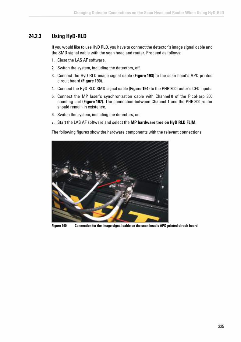
225
Changing Detector Connections on the Scan Head and Router When Using HyD-RLD
24.2.3 Using HyD-RLD
If you would like to use HyD RLD, you have to connect the detector's image signal cable and the SMD signal cable with the scan head and router. Proceed as follows:
1. Close the LAS AF software.
2. Switch the system, including the detectors, off.
3. Connect the HyD RLD image signal cable (Figure 193) to the scan head's APD printed circuit board (Figure 190).
4. Connect the HyD RLD SMD signal cable (Figure 194) to the PHR 800 router's CFD inputs.
5. Connect the MP laser's synchronization cable with Channel 0 of the PicoHarp 300 counting unit (Figure 197). The connection between Channel 1 and the PHR 800 router should remain in existence.
6. Switch the system, including the detectors, on.
7. Start the LAS AF software and select the MP hardware tree on HyD RLD FLIM.
The following figures show the hardware components with the relevant connections:
Figure 190: Connection for the image signal cable on the scan head's APD printed circuit board

226
Changing Detector Connections on the Scan Head and Router When Using HyD-RLD
Figure 191: PHR 800 router: CH 1 and CH 2 (left) to connect the two SMD signal cables of the MPD APDs (SPAD 1 and SPAD 2) and CH 1 IN and CH 2 IN of the CFD input (right) to connect the SMD signal cable from SP FLIM PMTs or HyD RLDs
Figure 192: SMD signal cable on the scan head's internal SP FLIM PMTs
Figure 193: Image signal cable on the HyD RLD, which is attached to the scan head's APD printed circuit board

227
Changing Detector Connections on the Scan Head and Router When Using HyD-RLD
Figure 194: Terminals for the FLIM signal cable on HyD RLD, which are connected to the CFD input connector on the PHR 800 router
Figure 195: MPD APD (SPAD): The upper cable of each SPAD unit is connected to the PHR 800 router (see Figure 191, terminals left); the respective lower cable is connected with the signal converter (see Figure 196)
Figure 196: Signal converters to connect the image signal cable of the MPD APDs (SPAD 1 and SPAD 2) to the scan head's APD printed circuit board (see Figure 190)

228
Changing Detector Connections on the Scan Head and Router When Using HyD-RLD
Figure 197: PicoHarp 300 counting unit: At Channel 0, the synchronization cable of the laser used (MP laser or white light laser) is connected

229
Switching Off the System
25 Switching Off the System
The TCS SP8 SMD is available in different versions. You must precisely follow the switch-off sequence that applies to your system variant. During FLIM experiments, it is also possible to operate the system with a compact supply unit.
NOTICE Damage to the instrument when not adhering to the switch-off sequence
The switch-off sequence must be followed! When not adhering to the below listed switch-off sequence, the laser can be damaged.
25.1 System with Flexible Supply Unit
1. Save the image data: To do so, click on the Experiments tab in LAS AF and click the Save all button.
Figure 198: Saving the image data in LAS AF
2. Close the LAS AF software: On the menu bar, select File > Exit.
Figure 199: Shutting down LAS AF

230
Switching Off the System
3. Save all relevant data in SymPhoTime and close the SymPhoTime software.
4. Turn off the lasers in the supply unit with the key switch on the main switch board of the flexible supply unit (see Figure 200, item 4).
Figure 200: Overview of the main switch board on the flexible supply unit
The emission warning indicator goes out.
5. If you are using a DSN-102 power supply, switch off the detectors by pressing the channel buttons on DSN 102.
6. If you are using the PDL 828 Sepia II laser driver, set the key switch to the "OFF" position.
7. If your system has a white light laser, check whether the emission warning indicator lights. Should the emission warning indicator on the front side of the white light laser be lit, press the key below it. This causes all internal white light laser components to shut off and the emission warning indicator to go out.
Figure 201: Emission Warning Indicator on the White Light Laser
8. Switch off the white light laser with the detachable-key switch on the front of the white light laser.

231
Switching Off the System
Figure 202: Key Switch for the White Light Laser
9. If you are using an external 355 and 405 (inclusive) UV laser, use the following key switch to turn it off (not possible for FLIM, FCS and FLCS images). The emission warning indicators go out.
Figure 203: Key switch on the power supply of external UV laser 355
Figure 204: Key switch on external UV laser 405
10. Switch off both external UV laser main power switches 355 and 405.

232
Switching Off the System
Figure 205: Power switch on external UV laser 355
Figure 206: Power switch on external UV laser 405
11. If you are using a HyD RLD, switch it off at its supply unit:
Figure 207: HyD RLD supply unit
12. If your system is equipped with an NDD detection unit, switch it off:

233
Switching Off the System
Figure 208: NDD detection unit
13. Shut down both workstations.
14. Switch off the lasers (see Figure 200, item 3), the scan head (see Figure 200, item 2), the workstation and the microscope (see Figure 200, item 1) on the flexible supply unit's main switch board.
15. Turn off any accessories being used.
16. Switch off the multiple socket outlet on the SMD trolley.
Observe the user manuals for external lasers
Please refer to the information from the documents provided by the laser manufacturer for the external lasers. Pay particular attention to the laser manufacturer's notes!
25.2 System with Compact Supply Unit (Only for FLIM)
1. Save the image data: To do so, click on the Experiments tab in LAS AF and click the Save all button.
Figure 209: Saving the image data in LAS AF
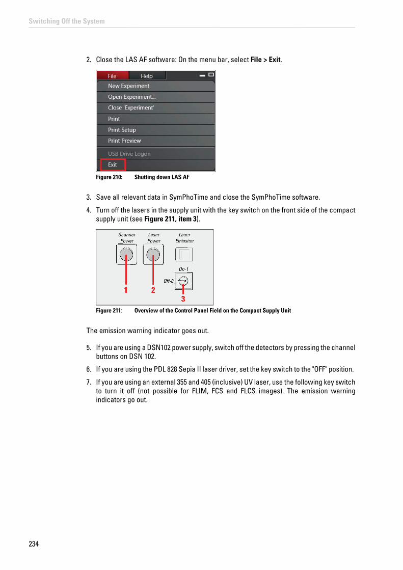
234
Switching Off the System
2. Close the LAS AF software: On the menu bar, select File > Exit.
Figure 210: Shutting down LAS AF
3. Save all relevant data in SymPhoTime and close the SymPhoTime software.
4. Turn off the lasers in the supply unit with the key switch on the front side of the compact supply unit (see Figure 211, item 3).
Figure 211: Overview of the Control Panel Field on the Compact Supply Unit
The emission warning indicator goes out.
5. If you are using a DSN102 power supply, switch off the detectors by pressing the channel buttons on DSN 102.
6. If you are using the PDL 828 Sepia II laser driver, set the key switch to the "OFF" position.
7. If you are using an external 355 and 405 (inclusive) UV laser, use the following key switch to turn it off (not possible for FLIM, FCS and FLCS images). The emission warning indicators go out.

235
Switching Off the System
Figure 212: Key switch on the power supply of external UV laser 355
Figure 213: Key switch on external UV laser 405
8. Switch off both external UV laser main power switches 355 and 405.
Figure 214: Power switch on external UV laser 355
Figure 215: Power switch on external UV laser 405
9. If you are using a HyD RLD, switch it off at its supply unit:

236
Switching Off the System
Figure 216: HyD RLD supply unit
10. If your system is equipped with an NDD detection unit, switch it off:
Figure 217: NDD detection unit
11. Shut down both workstations.
12. Switch off the lasers (see Figure 211, item 2) and the scan head (see Figure 211, item 1) on the front side of the compact supply unit.
13. Turn off the microscope by actuating the electronics box toggle switch (Figure 218, item 2). The readiness indicator (Figure 218, item 1) on the electronics box goes out.
Figure 218: Microscope electronics box
14. Turn off any accessories being used.

237
Switching Off the System
15. Switch off the multiple socket outlet on the SMD trolley.
Observe the user manuals for external lasers
Please refer to the information from the documents provided by the laser manufacturer for the external lasers. Pay particular attention to the laser manufacturer's notes!

238
Switching Off the System

239
Care and Cleaning
26 Care and Cleaning
Observe the user manuals provided
Always observe all of the user manuals provided for the individual components and peripheral devices.
WARNING Electric shock
Before cleaning, disconnect the entire system from the power supply. To do so, use the power switches of all components and disconnect all power cables from the power supply.
Ensure that no fluids enter the individual components or peripheral devices during cleaning!
26.1 Cleaning Surfaces
• Never use abrasives. Abrasives can scratch the surface and thus have a negative effect on the protection of the parts.
• Remove dust and loose dirt particles using a soft brush or lint-free cotton cloth.
• You may clean uncoated or plastic surfaces only using a dry cotton cloth or one moistened with a little water. Other cleaning agents can attack and tarnish the surface and cause it to become porous.
• Carefully remove clinging dirt on coated surfaces using a clean cloth slightly moistened with water.
• Never use acetone, xylene or nitro thinners as they attack the varnish.
26.2 Cleaning the Optical System
• Never open the objectives for cleaning.
• Remove dust with a fine, dry brush made from hair or with a clean, lint-free cloth moistened with distilled water.
• Prevent the optics and mechanical parts from coming into direct contact with acids, bases and other aggressive chemicals.
• Remove persistent dirt from glass surfaces using pure alcohol or chloroform.

240
Care and Cleaning
26.3 Cleaning Immersion Lenses
The immersion oil should be removed from oil immersion lenses immediately after it is applied:
1. First, remove the immersion oil using a clean cloth.
2. Once most of the oil has been removed with a clean tissue, a piece of lens tissue should be placed over the immersion end of the lens.
3. Apply a drop of the recommended solvent. Gently draw the tissue across the lens surface.
4. Repeat this procedure until the lens is completely clean. Use a clean piece of lens tissue each time.
Caution when objective lens is contaminated
If an objective lens is contaminated by unsuitable immersion oil or by the specimen, please contact your local Leica branch office. Certain solvents may dissolve the glue which holds the lens in place.
26.4 Care
• Always keep the optical components of the microscope clean.
• Never touch the optical components with your fingers or anything which may bear dust or grease.
• Always place dust caps over the objective nosepiece positions when no objective is in place in the nosepiece.
• When not in use, cover the system with a plastic cover or a clean piece of cotton cloth.
Avoid condensation
Allow the entire system to cool down to room temperature before covering the system with a dust cover. This prevents condensation from forming below it, which can enter the system and damage it.

241
Repairs and Service Work
27 Repairs and Service Work
WARNING Contamination with hazardous substances
Before each call from a service technician, the system has to be cleaned thoroughly to avoid contamination with hazardous biological materials. When returning system parts, it must be ensured that they are free of hazardous substances - otherwise they must not be sent. This applies in particular to systems that are located in biomedical research labs.
• Repairs and servicing may be performed only by service technicians authorized by Leica Microsystems CMS GmbH. Opening or working on the system in any way shall void any and all warranty claims.
• If housing parts have to be opened for repairs or service work, only Leica service technicians may be present in the room where the system is installed.
• Be sure to back up your data before any service or repair work is performed. Leica Microsystems CMS GmbH shall not be liable for any loss of data.
• Inside the system there are installed components that can cause potentially fatal injury if handled improperly. Opening these components will result in danger to people and the system. Therefore, only authorized Leica service personnel may open or work on the supply unit and the scan head.

242
Repairs and Service Work

243
Maintenance
28 Maintenance
NOTICE Damage to the instrument from not paying attention to the maintenance
Absolutely adhere to the prescribed maintenance intervals, as otherwise there can be serious damage to the instrument.
28.1 Having Coolant Replaced
The coolant (such as for scan head cooling and cooling the HyD RLD) must be replaced by Leica Service every two years.
You can find the safety data sheet for the coolant in the Chapter "Appendix".
Maintenance and replacement of the coolant may only be carried out by service technicians who are authorized by Leica Microsystems CMS GmbH. Opening or working on the system in any way shall void any and all warranty claims.
WARNING Contamination with hazardous substances
Before each call from a service technician, the system has to be cleaned thoroughly to avoid contamination with hazardous biological materials. When returning system parts, it must be ensured that they are free of hazardous substances - otherwise they must not be sent. This applies in particular to systems that are located in biomedical research labs.

244
Maintenance

245
Disassembly and Transport
29 Disassembly and Transport
Do not disassemble system components or housing parts yourself. Opening or working on the system in any way shall void any and all warranty claims.
Contact the Leica branch office in your country or your contact person if you need to move or transport the system or need to ship parts of it.
WARNING Contamination with hazardous substances
Before each call from a service technician, the system has to be cleaned thoroughly to avoid contamination with hazardous biological materials. When returning system parts, it must be ensured that they are free of hazardous substances - otherwise they must not be sent. This applies in particular to systems that are located in biomedical research labs.
Follow the notes provided in Chapter "Repairs and Service Work".

246
Disassembly and Transport

247
Disposal
30 Disposal
At the end of the product service life, please contact the Leica branch office in your country with regard to disposal.
Disposal
The system, its accessory components and consumable materials must not be disposed of together with general household waste! Be sure to follow the national laws and regulations.

248
Disposal

249
Troubleshooting
31 Troubleshooting
Make sure that all components of the TCS SP8 system as well as of the SMD upgrade are switched on.
31.1 Hardware Configuration Gets Lost or Software Needs to be Installed Again
The actual hardware configuration of your SMD upgrade (LSM trigger signal configuration, name of the TCSPC unit and corresponding settings, number of detection channels, etc.) is saved in a *.cfg file. Restoring the configuration using the CFG file is also useful if you have to reinstall the software.
Select the Restore from CFG file menu item in the Setup menu (Figure 219). The original settings of the SMD upgrade are stored in the Settings folder in the SymPhoTime program directory and in the MicroTime 200.cfg file on the external USB memory stick included in the standard delivery of the instrument.
Figure 219: SymPhoTime menu for restoring the configuration settings
If the hardware equipment is changed, the CFG file needs to be changed accordingly to adapt the software to the hardware changes. Please contact Leica Microsystems CMS GmbH in this case. As the system is delivered already configured, it is not recommended to change settings without the supervision of Leica Microsystems CMS GmbH.
31.2 The Instrument Is Losing Sensitivity
• We recommend installing a power meter in the lab in order to measure the laser intensities for selected wavelengths. This is especially true for FCS measurements, since the laser power is a crucial parameter for FCS.
• If you have purchased an SMD upgrade with one or two APD detectors attached, the performance of the instrument can be checked using FCS traces of a dye solution with a dye that can be effectively excited. At a given laser intensity, filters and objective, and distance to the cover slip surface, the molecular brightness is a stable, characteristic value that can be used to monitor the instrument's performance. Suitable dyes for various wavelengths:

250
Troubleshooting
• ATTO655 for 640 nm
• Rhodamine 6G for 532 nm or fluorescein (in a solution with a high pH value)
• ATTO488 for 470-nm excitation
• The molecular brightness is the count rate of the detectors divided by the number of molecules present in the detection volume. It is displayed in the FCS preview. In general, a 10-nM solution is used. For a day-to-day comparison, use the same laser power, ideally controlled using a power meter. A more detailed description of FCS measurements is provided in the point measurement section.
31.2.1 Causes for Decreased Performance
If a performance drop is noticed, the origin of the performance drop needs to be determined first. A drop in system performance may be caused by:
• Decreasing laser power: Check the laser intensity with a laser power meter. If the laser power from PQ lasers is too low, either the laser coupling unit has to be readjusted or the laser needs to be repaired or replaced. In this case, please contact customer support.
• Decreasing detection sensitivity:
• Misalignment of the TCS SP8: Contact Leica Service.
• Misalignment of the fiber decoupler for the fluorescent light: Contact Leica Service.
• Misalignment of the detector(s): In this case, please contact Leica customer support.
31.3 No FLIM Image is Displayed During Measurement
Can laser light be seen over the objective during measurement?
If not:
• Is the shutter open in LAS AF?
• Has the laser been activated by moving the corresponding slider?
• Is the multifunction port in the correct position?
• Is the pulse repetition rate of the pulsed lasers correct? This can be checked in the Time Trace preview window. When starting a measurement, at least background noise should be displayed (see Figure 148 at the right in Chapter 17.8). If the repetition rate is equal to 0, check whether the SYNCHRONIZATION is set to external on the PDL800B or PDL800D and whether the laser emission lamp is illuminated during scanning.
If yes:
• Do you see a dark count rate when activating the Time Trace tab in the Previewwindow? If not, check to ensure that the detectors are still activated. The DSN 102 (if present) deactivates a detector automatically if the count rate exceeds a certain limit. In
Observe additional manuals
For more information, refer to the manual for the PDL800B or D.

251
Troubleshooting
this case, the detector must be switched on again on the DSN.
• Check whether the correct SMD filter cube emission filters are placed in the X1 port adapter. If you have a 2 MPD detector unit from PicoQuant, make sure that the beam splitter is set to the correct position.
• When all detectors are on and background counts are displayed in the oscillator window, place a fluorescent specimen in the Leica microscope, configure all the settings for FLIM in LAS AF and start the scanning operation while the time trace measurement is active in the Preview window. The count rate should increase. If the count rate does not increase, make sure that the shutters in front of the detectors are not closed (the filter should sit in the filter holder correctly). Shutters should click quietly when opening and closing.
• Make sure that the X1 port setting of the Leica TCS SP8 is correct. In LAS AF, select the following in the beam path window:
• The --- position if you use external detectors
• The Mirror position if you use internal SP FLIM detectors.
• If the shutter is not the problem, take a FLIM image as described in Chapter 16.3. Although no counts are displayed, a PT3 file is generated. Calculate a time trace from your FLIM *.pt3 file, the same as if it were a point measurement, by choosing the MCS Trace button (only available if you have a software license for point analysis). The displayed time trace should contain the photon count. Select marker 1 - 3 to show line start, line stop, and frame markers that are transferred from the instrument. You may have to select a suited display range in order to display the marker signals. If there are no marker signals, check the cable connection between the Leica TCS SP8 and the SMD upgrade. If there are no marker signals even though the connection is intact, contact PicoQuant.

252
Troubleshooting
31.4 How to Handle PQ Error Codes in LAS AF
Error messages generated in SymPhoTime are also displayed in LAS AF. The following table provides a list of possible messages and recommended user actions.
Table 23: SymPhoTime error codes displayed in LAS AF and recommended measures
PQ error code displayed in LAS AF Recommended user action
PQ_ERRCODE_NO_ERROR Continue
PQ_ERRCODE_MEASUREMENT_READY
Retry
PQ_ERRCODE_USER_BREAK Measurement was stopped by user-> Retry
PQ_ERRCODE_MESSAGE_CORRUPTED =-1
Network communication problem -> Retry, report to Leica
PQ_ERRCODE_SERVER_BUSY = -2 Retry or restart system
PQ_ERRCODE_MESSAGE_TIMEOUT = -3
Retry
PQ_ERRCODE_INVALID_REC_VERSION =-10
SymPhoTime and LAS AF version incompatible -> Latest software versions installed?
PQ_ERRCODE_MEASUREMENT_TIMEOUT =-100
Retry
PQ_ERRCODE_FIFO_OVERRUN = -101 Count rates are too high -> Lower laser intensity
PQ_ERRCODE_DMA_ERROR = -102 Retry
PQ_ERRCODE_OSCILLOSCOPE_RUNNING = -103
Stop oscilloscope measurement in SymPhoTime
PQ_ERRCODE_HARDWARE_INIT = -104 Restart PicoHarp and SymPhoTime computer
PQ_ERRCODE_TTTR_INIT = -105 Restart PicoHarp and SymPhoTime computer
PQ_ERRCODE_TTTR_RUNNING = -106 Either another measurement is active -> Stop measurement in SymPhoTime or SymPhoTime is busy with saving data -> In an FCS or FLIM time series, increase the time between individual measurements
PQ_ERRCODE_NO_WORKSPACE = -107 Open workspace in SymPhoTime
PQ_ERRCODE_FILE_EXISTS = -108 Choose new file name in LAS AF that does not appear in the SymPhoTime workspace
PQ_ERRCODE_FILE_CREATE = -109 Folder is write-protected, choose other folder for workspace in SymPhoTime
PQ_ERRCODE_GROUPNAME_TOO_LONG =-110
Group name must be not longer than 63 characters -> Choose shorter base name in LAS AF
PQ_ERRCODE_FILENAME_TOO_LONG =-111
File name must be no longer than 255 characters -> Choose shorter base name in LAS AF
PQ_ERRCODE_TIMESTAMP_ARRAY_TOO_LONG =-112
Reduce frame size of FLIM image in x. Contact Leica
PQ_ERRCODE_INVALID_LICENSE =-999
The software license is not valid for this kind of measurement
PQ_ERRCODE_UNKNOWN_ERROR = -9999
Retry

253
Contact
32 Contact
If you have any further questions, please directly contact your country's Leica branch office or your local contact person. The appropriate contacts can be found on the Internet under:
http://www.confocal-microscopy.com

254
Contact

255
Recommended Literature
33 Recommended literature
Publications related to the LSM FLIM / FCS upgrade hardware, software, and underlying key technologies:
• Wahl M., Koberling F., Patting M., Rahn H., Erdmann R.: Time-resolved confocal fluorescence imaging and spectroscopy system with single molecule sensitivity and sub-micrometer resolution. Current Pharmaceutical Biotechnology, Ed. 05, S.299-308 (2004)
• Koberling F., Wahl M., Patting M., Rahn H.-J., Kapusta P., Erdmann R.: Two-channel fluorescence lifetime microscope with two colour laser excitation, single-molecule sensitivity, and submicrometer resolution. Proceedings of SPIE, 5143, p.181-192 (2003)
• Ortmann U., Dertinger T., Wahl M., Rahn H., Patting M., Erdmann R.: Compact TCSPC upgrade package for laser scanning microscopes based on 375 to 470 nm picosecond diode lasers Proceedings of SPIE 5325, S.179 (2004)
• Benda A., Hof. M., Wahl M., Patting M., Erdmann R., Kapusta P.: TCSPC upgrade of a confocal FCS microscope. Review of Scientific Instruments, Ed. 76, 033106 (2005)
Further literature can be found in the help menu of the SymPhoTime software.
The following application and technical notes are available from PicoQuant upon request:
• Koberling F., Schuler B.: FRET analysis of freely diffusing molecules using the MicroTime 200
• Krämer B., Koberling F.: Lifetime based hydrophobicity analysis of hepatocytes using the MicroTime 200
• Krämer B., Koberling F., Tannert A., Korte T., Hermann A.: Lifetime based analysis of lipid organization in hepatocytes using the MicroTime 200
• Ortmann U., Dertinger T., Wahl M., Bülter A., Erdmann R., Kahl H.: Compact FLIM and FCS upgrade kit for Olympus FV 300 and FV 1000 laser scanning microscopes
• Wahl M.: Time-correlated single photon counting in fluorescence lifetime analysis
• Wahl M.: Time tagged time resolved fluorescence data collection
Numerous measurement examples are published on the PicoQuant website. Visit the LSM FLIM / FCS Upgrade section on the following website:
http://www.picoquant.com/_systems.htm

256
Recommended Literature

257
Abbreviations
34 Abbreviations
AOBS Acousto-optical beam splitter
AOTF Acousto-optical tunable filter
APD Avalanche Photo Diode
AQR Product description of the APD by Perkin Elmer
BNC British Naval Connector or Bayonet Nut Connector or Bayonet Neill Concelman
CCD Charge-Coupled Device
CFD Constant Fraction Discriminator
cps Counts per second
cw Continuous wave (not pulsed)
DSN Product name of the Dual SPAD Power Supply
EOM Electro-optical modulator
FCCS Fluorescence Cross-Correlation Spectroscopy
FCS Fluorescence Correlation Spectroscopy
LCU Laser Coupling Unit
FIFO First In, First Out (buffer type)
FLIM Fluorescence Lifetime Imaging
FRET Förster Resonance Energy Transfer
FWHM Full Width at Half Maximum
IO Input-Output
IPS Instrument Parameter Setting
IRF Instrument Response Function
LAS AF Leica Application Suite Advanced Fluorescence
LED Light Emitting Diode
LSM Laser Scanning Microscope
MCS Multichannel Scaling
MPD Micro Photon Devices (manufacturer of the SPADs)
NDD Non-descanned detector
OD Optical Density
PC Personal Computer
PCI Peripheral Component Interface
PDL Product name for PQ Pulsed Laser Drivers
PE Perkin Elmer
PIE Pulsed Interleaved Excitation
PMT Photomultiplier Tube
RGB Red-Green-Blue (color scheme)
ROI Region of Interest
SHG Second Harmonic Generation
SMA SubMiniature version A (connector type)
SMD Single Molecule Detection
SPAD Single Photon Avalanche Diode

258
Abbreviations
SPT SymPhoTime (software from PicoQuant)
SYNC Synchronization (signal)
TCSPC Time-Correlated Single Photon Counting
TTL Transistor-Transistor Logic
TTTR Time-Tagged Time-Resolved

259
Appendix
35 Appendix
35.1 Patents
The Leica TCS SP8 product is protected by US patents:
5,886,784; 5,903,688; 6,137,627; 6,222,961; 6,285,019; 6,311,574; 6,355,919; 6,423,960; 6,433,814; 6,444,971; 6,466,381; 6,510,001; 6,614,031; 6,614,525; 6,614,526; 6,654,165; 6,657,187; 6,677,579; 6,678,443; 6,687,035; 6,738,190; 6,754,003; 6,771,405; 6,801,359; 6,831,780; 6,850,358; 6,852,964; 6,867,899; 7,016,101.
Further patents are pending.
The Leica TCS SP8 X product is protected by US patents:
5,886,784; 5,903,688; 6,137,627; 6,222,961; 6,285,019; 6,311,574; 6,355,919; 6,423,960; 6,433,814; 6,444,971; 6,466,381; 6,510,001; 6,611,643; 6,614,031; 6,614,525; 6,614,526; 6,654,165; 6,657,187; 6,677,579; 6,678,443; 6,687,035; 6,710,918; 6,738,190; 6,754,003; 6,771,405; 6,796,699; 6,801,359; 6,831,780; 6,850,358; 6,852,964; 6,867,899; 6,888,674; 6,898,367; 6,958,858; 7,016,101; 7,110,645; 7,123,408; 7,257,289; 7,679,822
Further patents are pending.
35.2 Safety Data Sheets from Third-Party Manufacturers
The scan head is liquid-cooled. Following are the safety data sheets from the manufacturer "Innovatek" for the coolant used.

EEC - SAFETY DATA SHEET Gem. 91/155/EG; 2001/58/EG
innovatek OS GmbH Dated: www.innovatek.deFebruary 28st 2011 / innovatek Protect application mixture [email protected]
1
1. Substance/preparation and company name
Trade name: innovatekProtect IP – application mixture company: innovatek OS GmbH, Stadtweg 9, 85134 Stammham Tel: 08405/92590 Fax: 08405/925921 Emergency phone No.: +49 (0) 8405/92590
2. Composition / information on ingredients
Chemical nature: Ethylene glycol (ethane diol). Corrosion inhibitors. Hazardous Compounds: Ethanediol Content (w/w): >25% +-5% CAS No: 107-21-1 EC No: 203-473-3 Hazard symbol: Xn INDEX No: 603-027-00-1 R-phrases: 22 2-ethylhexanoic acid, Content (w/w): 0,5 % - 0,75 % CAS No: 19766-89-3 sodium salt EC No: 243-283-8 Hazard symbol: Xn R-phrases: 63
The wording of the hazard symbols and R-phrases is specified in Chapter 16 if dangerous ingredients are mentioned.
3. Hazard identification
Special risks for people and environment: Damages caused to someone´s health by swallowing.
4. First aid measures
General advice: Remove contaminated clothing. If inhaled: If difficulties occur after vapour/aerosol has been inhaled: fresh air, summon physician. On skin contact: Wash thoroughly with soap and water. On contact with eyes: Wash affected eyes for at least 15 minutes under running
water with eyelids held open. On ingestion: Rinse mouth immediately and then drink plenty of water,
seek medical attention. Note to physician: Symptomatic treatment (decontamination, vital functions).
Administer 50 ml of pure ethanol in a drinkable concentration.
5. Fire fighting measures
Suitable extinguishing media: Water spray, alcohol-resistant foam, dry extinguishers, carbon dioxide (CO2).
Special protective In case of fire, wear a self contained breathing apparatus. equipment:Further information: The degree of risk is governed by the burning substance and
the fire conditions. Contaminated extinguishing water must be disposed of in accordance with local legislation.
260
Appendix
Figure 220: innovatek Protect application mixture safety data sheet page 1

EEC - SAFETY DATA SHEET Gem. 91/155/EG; 2001/58/EG
innovatek OS GmbH Dated: www.innovatek.deFebruary 28st 2011 / innovatek Protect application mixture [email protected]
2
6. Accidental release measures
Personal precautions: Avoid excessive contact with skin and eyes. In case of release of larger amounts remove contaminated clothing and wash bo- dy down thoroughly with water. Hand protection. Pick up im- mediately as product renders floors slippery.
Environmental pre- Contain contaminated water/firefighting water. Do not discharge cautions: product into natural waters without pretreatment (biological
treatment plant).Methods for cleaning Bind the liquid by using suitable absorbent material (saw dust, up / taking up: sand, etc.) and dispose of in accordance with the regulations.
Wash away spills thoroughly with large quantities of water. In case of release of larger quantities which might flow into the draining system or waters, contact appropriate authorities.
7. Handling and storage
Handling: Ensure thorough ventilation of stores and work areas. Protection against Take precautionary measures against static discharges. fire and explosion: If exposed to fire, keep containers cool by spraying with water. Storage: Product is hygroscopic. Containers should be stored tightly
sealed in a dry place. Storage in galvanized containers is not recommended.
8. Exposure controls and personal protection
Components with workplace control parameters: 107-21-1: Ethylene glycol MAK value (D): 26 mg/m³ = 10 ppm (TRGS 900 (DE)). Top limit
category 1. There is no reason to fear a risk of damage to the developing embryo when the MAK value is adhered to. Skin resorption hazard: wear suitable gloves (see below).
Personal protective equipment Respiratory Protection: Do not inhale gases/vapours/aerosols. Hand protection: Chemical resistant protective gloves (EN 374). Recommended:
nitrile rubber, protective index 6. Manufacturers directions for use should be observed because of great diversity of types.
Eye protection: Safety glasses with side-shields (frame goggles, EN 166) General safety and The usual precautions for the handling of chemicals must hygiene measures: be observed.
9. Physical and chemical properties
Form: Liquid Colour: Colourless Odour: Product specific pH value ( 500 g/l, 20 °C): 7.0 - 9.0 Solidification temperature: < -10 °C (DIN/ISO 3016) Boiling point/range: >= 105 °C (ASTM D 1120) Flash point: >120 °C (only valid für the Ethylenglykol part)(DIN/ISO 2592) Lower explosion limit: 3.0 % vol. (only valid für the Ethylenglykol – part)
261
Appendix
Figure 221: innovatek Protect application mixture safety data sheet page 2

EEC - SAFETY DATA SHEET Gem. 91/155/EG; 2001/58/EG
innovatek OS GmbH Dated: www.innovatek.deFebruary 28st 2011 / innovatek Protect application mixture [email protected]
3
Upper explosion limit: 15.0 % vol (only valid für the Ethylenglykol – part) Ignition point: >200°C (DIN 51794)(only valid für the Ethylenglykol – part) Vapor pressure (20°C): 2 mbar (DIN 51757) Density (20°C): ca. 1.04 g/cm³ Miscibility with water: optional mixable Solubility (quantitative) solvent: polar solvents: soluble Viscosity (kinematic, 20°C): 3-5 mm²/s
10. Stability and reactivity
Substances to avoid: Strong oxidizing agents. Hazardous reactions: No hazardous reactions when stored and handled according
to instructions. Hazardous decomposition No hazardous decomposition products if stored and handled products: as prescribed/indicated.
11. Toxicological data
LD50/oral/rat: >2000 mg/kg (only valid für the Ethylenglykol – part) LD50/dermal/rabbit: non- irritant (only valid für the Ethylenglykol – part) Primary skin irritation/rabbit/: non-irritant
Information on Ethylene glycol:Further information: Developmental toxicity was observed after oral ingestion of
high doses in studies with rats and mice, but this effect was not seen in a study with rabbits.
Experiences in humans: Lethal dose if swallowed approx. 1.5 g/kg body weight. Lethal dose approx. 90-110 g for adults, and correspondingly less for children. Smaller doses can result in: consciousness is affec- ted, kidney damage, damage to the central nervous system.
Additional information: The statements are based on the properties of the individual components. There is no reason to fear a risk of damage to the developing embryo or fetus when the MAK value is ad- hered to.The whole of the information available provides no indication of a carcinogenic effect.
12. Ecological information
Ecotoxicity: Toxicity to fish: Leuciscus idus/LC50 (96 h): >400 mg/l Aquatic invertebrates: daphnia magna/EC50 (48 h): >400 mg/l Aquatic plants: algae/EC50 (72 h): >400 mg/l Microorganisms/Effect on activated sludge: Inhibition of de- gradation activity in activated sludge is not to be anticipated during correct introduction of low concentrations.
Persistence and Elimination information: Degradability: Test method: OECD 301A (new version)
Method of analysis: DOC reduction Degree of elimination: >70 %Evaluation: readily biodegradable.
Additional information: Other ecotoxicological advice: Do not release untreated into na-
262
Appendix
Figure 222: innovatek Protect application mixture safety data sheet page 3

EEC - SAFETY DATA SHEET Gem. 91/155/EG; 2001/58/EG
innovatek OS GmbH Dated: www.innovatek.deFebruary 28st 2011 / innovatek Protect application mixture [email protected]
4
tural waters. The product has not been tested. The statement was derived from the properties of the individual components.
13. Disposal considerations
innovatekProtect must be dumped or incinerated in accordance with local regulations.
Contaminated Uncontaminated packs can be reused. Packs that cannot packaging: be cleaned should be disposed of in the same manner as the contents.
14. Transport information
Not dangerous according to transport regulations (ADR RID ADNR IMDG / GGVSee ICAO / IATA)
15. Regulatory information
Regulations of the European union (Labelling) / National legislation / Regulations: Directive 1999/45/EEC („Preparation Directive“) Hazard Symbol: Xn: Harmful R-phrases: 22: Harmful if swallowed S-phrases: 2: Keep out of reach of children
24/25: Avoid contact with skin and eyes 46: If swallowed, seek medical advice immediately
and show this container or label
Hazard determinant componentfor labelling: 1,2-Ethanediol Other regulations: Classification according to VbF (Germany): None
Categorization according to TA-Air (Germany)3.1.7 Category III Water compromises category (attachment 4 of VwVwS(Germany) from 17.Mai 1999): (1) low water compromising
16. Further Information
Full text of hazard symbols and R-phrases if mentioned as hazardous components in chapter 2: Xn: Harmful 22: Harmful if swallowed. 63: Possible risk of harm to the unborn child.
Vertical lines in the left hand margin indicate an amendment from the previous version. This safety data sheet is intended to provide information and recommendations as to: 1. how to handle chemical substances and preparations in accordance with the essential require- ments of safety precautions and physical, toxicological, and ecological data. 2. how to handle, store, use, and transport them safely. No liability for damage occured in connection with the use of this information or with the use, application, adaption, or processing of the products here described will be accepted. An ex- ception will be made in the case that our legal representatives should come to be held re-
263
Appendix
Figure 223: innovatek Protect application mixture safety data sheet page 4

EEC - SAFETY DATA SHEET Gem. 91/155/EG; 2001/58/EG
innovatek OS GmbH Dated: www.innovatek.deFebruary 28st 2011 / innovatek Protect application mixture [email protected]
5
sponsible and liable by reason of intent or gross negligence. No liability will be accepted for damage indirectly incured. We provide this information and data according to our present level of knowledge and expe- rience. No assurances concerning the characteristics of our product are hereby furnished.
264
Appendix
Figure 224: innovatek Protect application mixture safety data sheet page 5

265
Appendix
35.3 Compliance
This system has been tested and meets the requirements of the following standards:
IEC/EN 61010-1:2011 "Safety requirements for electrical equipment for measurement, control and laboratory use - Part 1: General requirements"
IEC/EN 60825-1:2007 "Safety of laser products - Part 1: Equipment classifications and requirements"
IEC/EN 61326-1:2006 "Electrical equipment for measurement, control and laboratory use - EMC requirements - Part 1: General requirements (class A)"
This is a Class A instrument for use in buildings that do not include domestic premises and buildings not directly connected to a low-voltage power supply network that supplies buildings used for domestic purposes.
You can find the Declaration of Conformity for the system on the following page of this User Manual.
For use in the USA:
CDRH 21 CFR 1040.10: Laser Products U.S. Food and Drug Administration (FDA) "Complies with FDA performance standards for laser products except for deviations pursuant to laser notice No. 50, dated June 24, 2007".
For the USA (area of validity of the CDRH/FDA), the designations of the laser class are to be changed in the text from 3B to IIIb and Class 4 to IV.

266
Appendix
Figure 225: Declaration of conformity

267
Appendix
35.4 People's Republic of China
- Administrative Measures on the Control of Pollution Caused by Electronic Information Products -
Note: The actual product may or may not include all the part types listed above.
printed circuit boards X O O O O O
electronic components
X O O O O O
mechanical parts
X O O X O O
optical components
X O X O O O
cables
O O O O X X
light sources
X X X O O O

268
Appendix


10
Leica Microsystems CMS GmbH Phone: +49 621 7028 - 0Am Friedensplatz 3 Fax: +49 621 7028 - 1028D-68165 Mannheim (Germany) http://www.leica-microsystems.com
Copyright © Leica Microsystems CMS GmbH • All rights reserved
User Manual Leica TCS SP8 SMDOrder number: 158000062 | V: 00
www.leica-microsystems.com