Embed Size (px)
Citation preview
Catalog Number HQ40d18
HQ Series Portable Meters
USER MANUAL
September 2006, Edition 5
© Hach Company, 2006. All rights reserved.
Table of Contents
Section 1 General Information ........................................................................................................ 71.1 Safety Information ....................................................................................................................... 7
1.1.1 Use of Hazard Information ................................................................................................. 71.1.2 Precautionary Labels ......................................................................................................... 7
1.2 Product Overview ........................................................................................................................ 81.3 Meter Description ........................................................................................................................ 8
Section 2 Specifications ................................................................................................................... 9Section 3 Installation ...................................................................................................................... 11
3.1 Unpacking the Instrument ......................................................................................................... 113.2 AC Power and Batteries ............................................................................................................ 12
3.2.1 Battery Power .................................................................................................................. 123.2.2 AC Power ......................................................................................................................... 14
3.3 Turning the Meter On and Off ................................................................................................... 143.4 Probe Connection ..................................................................................................................... 143.5 Data Transfer ............................................................................................................................ 16
Section 4 System Start Up ............................................................................................................. 194.1 Basic Start Up Overview ........................................................................................................... 194.2 Meter User Interface and Navigation ........................................................................................ 20
4.2.1 Keypad Description .......................................................................................................... 204.2.2 Display Description (Single and Dual) ............................................................................. 21
4.2.2.1 Using Single Screen Mode ...................................................................................... 214.2.2.2 Using Dual Screen Mode (HQ40d only) .................................................................. 21
4.3 Selecting the Language ............................................................................................................ 224.4 Setting the Date and Time ........................................................................................................ 22
Section 5 Standard Operation ....................................................................................................... 255.1 Setting the Sample and Operator Identification ........................................................................ 25
5.1.1 Sample ID ........................................................................................................................ 255.1.1.1 Creating a New Sample ID ...................................................................................... 255.1.1.2 Selecting a Sample ID ............................................................................................. 265.1.1.3 Deleting a Sample ID .............................................................................................. 26
5.1.2 Operator ID ...................................................................................................................... 275.1.2.1 Creating a New Operator ID .................................................................................... 275.1.2.2 Selecting an Operator ID ......................................................................................... 275.1.2.3 Deleting an Operator ID .......................................................................................... 28
5.2 Using the Data Log ................................................................................................................... 285.2.1 Storing Data ..................................................................................................................... 285.2.2 Viewing Stored Data ........................................................................................................ 285.2.3 Viewing Probe Data ......................................................................................................... 295.2.4 Deleting Data ................................................................................................................... 30
5.3 Transferring Data ...................................................................................................................... 315.3.1 Transferring Data Options ................................................................................................ 31
5.3.1.1 Selecting Printed Report Types .............................................................................. 315.3.1.2 Including Column Headers in Data Files ................................................................. 32
5.3.2 Sending Data to a Printer ................................................................................................. 335.3.3 Sending Data to a Flash Memory Stick ............................................................................ 335.3.4 Sending Data to a Computer using the HQd PC Application Software ............................ 345.3.5 Sending Probe Calibration Data ...................................................................................... 35
5.4 Viewing Printed Data Log Reports ............................................................................................ 365.4.1 Report Names .................................................................................................................. 365.4.2 Sample Results ................................................................................................................ 36
5.4.2.1 Basic Reports .......................................................................................................... 36
3
Table of Contents
5.4.2.2 Advanced Reports ...................................................................................................375.4.2.3 Total Reports ...........................................................................................................37
5.4.3 Calibration Results ...........................................................................................................385.4.4 Check Standard Results ...................................................................................................39
5.5 Viewing Printed Calibration Reports ..........................................................................................405.5.1 Current Calibration Reports ..............................................................................................405.5.2 Calibration History Reports ...............................................................................................41
5.6 Viewing Downloaded Data Files ................................................................................................425.7 Archiving and Exchanging User Methods .................................................................................45
Section 6 pH Operation and Methods .........................................................................................476.1 Calibrating the pH Probe ...........................................................................................................47
6.1.1 Calibration Errors ..............................................................................................................486.1.1.1 Standard Not Recognized .......................................................................................486.1.1.2 Slope Error ..............................................................................................................48
6.2 Taking a pH Measurement ........................................................................................................496.3 Running Check Standards ........................................................................................................49
6.3.1 Automatic or Custom Check Standards ...........................................................................496.3.2 Measuring Check Standards ............................................................................................506.3.3 Deferring a Check Standard .............................................................................................51
6.4 Setting the pH Method ...............................................................................................................516.5 Modify Current Method Menu for pH Summary ........................................................................52
6.5.1 Modifying pH Methods ......................................................................................................536.5.2 Modifying the pH Measurement Options ..........................................................................536.5.3 Modifying the pH Calibration Options ...............................................................................556.5.4 Modifying the pH Check Standard Options ......................................................................59
6.5.4.1 Selecting a Check Standard Buffer .........................................................................596.5.4.2 Using a Custom Check Standard ............................................................................596.5.4.3 Editing the Check Standard Reminder Options .......................................................606.5.4.4 Editing the Acceptance Criteria for Check Standards .............................................61
6.5.5 Modifying the pH Measurement Units ..............................................................................62Section 7 Conductivity Operation and Methods .......................................................................63
7.1 Calibrating the Conductivity Probe ............................................................................................637.2 Taking a Conductivity, Salinity, Resistivity, or TDS Measurement ............................................647.3 Running Check Standards Manually or Automatically ..............................................................65
7.3.0.1 Deferring a Check Standard ....................................................................................667.4 Setting the Conductivity Method ................................................................................................667.5 Modify Current Method Menu for Conductivity Summary ..........................................................67
7.5.1 Modifying a Conductivity Method ......................................................................................687.5.2 Modifying the Conductivity Parameter ..............................................................................687.5.3 Modifying the Conductivity Measurement Options ...........................................................697.5.4 Modifying the Conductivity Calibration Options ................................................................727.5.5 Modifying Conductivity Check Standard Options .............................................................75
Section 8 LDO Operation and Methods ......................................................................................798.1 Taking a Dissolved Oxygen Measurement ................................................................................798.2 Calibrating the LDO Probe ........................................................................................................79
8.2.1 Calibration Error- Slope Out of Range ..............................................................................818.3 Setting LDO Methods ................................................................................................................818.4 Modify Current Method Menu Summary ...................................................................................82
8.4.1 Entering a New LDO Method ............................................................................................828.4.2 Modifying an LDO Method ................................................................................................838.4.3 Modifying LDO Measurement Options .............................................................................838.4.4 Modifying the LDO Measurement Units ............................................................................86
4
Table of Contents
8.4.5 Modifying the LDO Calibration Standard ......................................................................... 868.4.5.1 Selecting Water-Saturated Air as the Calibration Standard .................................... 868.4.5.2 Selecting a Water Sample as the Calibration Standard .......................................... 87
8.4.6 Selecting a LDO Method .................................................................................................. 888.4.7 Deleting a Method ............................................................................................................ 89
Section 9 Advanced Operations .................................................................................................. 919.1 Meter Options Menu- Full Access ............................................................................................. 919.2 Operator Meter Options Menu .................................................................................................. 919.3 Using Access Control ................................................................................................................ 92
9.3.1 Turning Access Control On .............................................................................................. 929.3.2 Turning Access Control Off .............................................................................................. 93
9.4 Running Check Standards ........................................................................................................ 939.5 Setting the Measurement Mode ................................................................................................ 94
9.5.1 Setting Auto Measurement Intervals ................................................................................ 959.5.2 Starting Interval Measurements ....................................................................................... 969.5.3 Preventing Data Log Overflow in Interval Reading Mode ................................................ 96
9.6 Viewing Instrument Information ................................................................................................ 979.7 Setting the Display Options ....................................................................................................... 979.8 Setting the Sound Options ........................................................................................................ 989.9 Setting the Date and Time ........................................................................................................ 999.10 Changing the Temperature Units ............................................................................................ 999.11 Language ................................................................................................................................ 99
Section 10 Maintenance ............................................................................................................... 10110.1 General Meter Cleaning ........................................................................................................ 10110.2 General Probe Cleaning ....................................................................................................... 10110.3 Battery Replacement ............................................................................................................ 10110.4 Updating Instrument Software .............................................................................................. 101
Section 11 Parts and Accessories ............................................................................................. 10311.1 Parts ...................................................................................................................................... 10311.2 Accessories ........................................................................................................................... 10311.3 Consumables ........................................................................................................................ 104
Section 12 How to Order .............................................................................................................. 107Section 13 Repair Service ............................................................................................................ 109Section 14 Certification ................................................................................................................ 111Section 15 Limited Warranty ....................................................................................................... 113Appendix A Connecting the Citizen Handy Printer PD-24 ................................................... 115Index.................................................................................................................................................... 117
5
Section 1 General Information
1.1 Safety InformationPlease read this entire manual before unpacking, setting up, or operating this equipment. Pay attention to all danger and caution statements. Failure to do so could result in serious injury to the operator or damage to the equipment.
To ensure that the protection provided by this equipment is not impaired, do not use or install this equipment in any manner other than that specified in this manual.
1.1.1 Use of Hazard Information
DANGERIndicates a potentially or imminently hazardous situation which, if not avoided, could result in death or serious injury.
CAUTIONIndicates a potentially hazardous situation that may result in minor or moderate injury.
Important Note: Information that requires special emphasis.
Note: Information that supplements points in the main text.
1.1.2 Precautionary LabelsRead all labels and tags attached to the instrument. Personal injury or damage to the instrument could occur if not observed. A symbol, if noted on the instrument, will be included with a danger or caution statement in the manual.
This symbol, if noted on the instrument, references the instruction manual for operation and/or safety information.
Electrical equipment and manufacturer supplied accessories marked with this symbol may not be disposed of in European public disposal systems after 12 August of 2005. In conformity with European local and national regulations (EU Directive 2002/96/EC), European electrical equipment users must now return old or end-of life equipment to the Producer for disposal at no charge to the user. Note: For return for recycling, please contact the equipment producer or supplier for instructions on how to return end-of-life equipment, producer-supplied electrical accessories, and all auxiliary items for proper disposal.
This symbol, if noted on the product, indicates the need for protective eye wear.
7
General Information
1.2 Product OverviewThe HQ Series Portable Meters measure various parameters when used with IntelliCAL™ probes such as pH, conductivity, salinity, total dissolved solids (TDS), or dissolved oxygen (using Hach's patented luminescent dissolved oxygen probes, LDO®). The meter automatically recognizes the type of probe that is connected to the meter. IntelliCAL probes store the unique serial number, current calibration, and calibration history. When the default settings are used, an operator can take measurements right out of the box.
Data is easily managed by using the settings for operator ID, sample ID, and data storage. Supervisory control can be set by using the access function. Settings for measurement and calibration are stored as methods. The default method for each parameter follows suggested USEPA measurement techniques.
1.3 Meter DescriptionThe HQ series meters are available in four models:
• HQ11d—pH/mV
• HQ14d—conductivity, salinity, total dissolved solids (TDS)
• HQ30d—pH, conductivity, salinity, total dissolved solids (TDS) or dissolved oxygen (LDO), 1 probe connector
• HQ40d—pH, conductivity, salinity, total dissolved solids (TDS), or dissolved oxygen (LDO), 2 probe connectors.
Other features:
• Auto probe recognition including serial number
• Methods containing parameter settings for regulatory control
• Supervisory access control
• Long sensor life, LDO
• No polarization time, LDO
• Internal data storage of 500 results
• Sample ID and Operator ID for data traceability
• Adjustable automatic shut-off for extended battery life
• Automatic correction for barometric pressure and temperature, LDO
• IP67 (waterproof to 1 meter for 30 minutes, excluding battery housing. Battery compartment submersible to 2 feet for 15 seconds)
• Connectivity to PC/printer/flash memory stick/keyboard
• Power from four alkaline or Nickel Metal Hydride (NiMH) AA batteries, or AC adapter
8
Section 2 Specifications
Specifications are subject to change without notice.
Meter Enclosure
Enclosure Meter: IP67, waterproof to 1 meter for 30 minutesBattery Compartment: water resistant to 2 feet for 15 seconds
Power Requirements (internal) AA Alkaline or Nickel Metal Hydride (NiMH) Batteries (4)
Power Requirements (external USB/DC power adaptor)
100–240 V, 50/60 Hz input; 4.5 to 7.5 V (7 VA) output (center contact +, outer shield -)
Storage Temperature –20 to +60 °C (–4 to +140 °F)
Operating Temperature 0 to +60 °C (32 to 140 °F)
Operating Humidity 90% (non-condensing)
Weight 0.75 lb/11.6 oz/330 g 0.95 lb/15.2 oz/430 g (with four AA alkaline batteries installed)
Inputs
5-pin Custom M-12 for probes Meters accept IntelliCAL probes (HQ11d pH only; HQ14d conductivity only)
8-Pin Connector for USB and external AC power The 8-pin connector enables USB and external AC power connectivity
pH IntelliCAL Probes (standard and rugged)
pH RangePHC301 (refillable): 0.0–14.0 pH
PHC101 (gel filled): 2.0–14.0 pH
Sodium (Alkalinity) Error –0.6 pH at pH 12.6 in 1 M NaOH
Temperature Range 0.0–80.0 ºC
Temperature Accuracy ±0.3 ºC
Warranty PHC301 probe is covered by a one-year warrantyPHC101 probe is covered by a six-month warranty
LDO IntelliCAL Probes (standard and rugged)
Dissolved Oxygen Range0.1–20.0 mg/L (ppm)1–200% saturation
Dissolved Oxygen Accuracy±0.1 mg/L for 0.1–8 mg/L±0.2 mg/L for greater than 8.0 mg/L
% Saturation 1.0%
Temperature Range 0–50 ºC
Temperature Resolution 0.1 ºC
Temperature Accuracy ± 0.3 ºC
WarrantyProbe is covered by a three-year warranty.Sensor cap is covered by a one-year warranty.
Conductivity IntelliCAL Probe
Conductivity Range 0.01 µS/cm to 200.0 mS/cm
Conductivity Resolution
0.01–19.99 µS/cm: 0.01 µS/cm20.0–199.9 µS/cm: 0.1 µS/cm200.0–1999.0 µS/cm: 1.0 µS/cm2.0–19.99 mS/cm: 0.01 mS/cm20.0–200.0 mS/cm: 0.1 mS/cm
Conductivity Accuracy ±0.5% of Reading
TDS Range 0 to 50,000 mg/L as NaCl
TDS Accuracy ±0.5% of Reading
9
Specifications
Conductivity IntelliCAL Probe (continued)
TDS Resolution
0.0–199.9 mg/L: 0.1 mg/L200.0–1999.0 mg/L: 1.0 mg/L2.0–19.99 g/L: 0.01 g/L20.0–50.0 g/L: 0.1 g/L
Salinity Range 0 to 42 ppt (‰)
Salinity Accuracy ±0.1 ppt
Salinity Resolution 0.01 ppt
Temperature Range –10.0 to 110.0 ºC
Temperature Accuracy ±0.3 ºC
Warranty Probe is covered by a one-year warranty.
Outputs
USB Peripheral and Host
10
Section 3 Installation
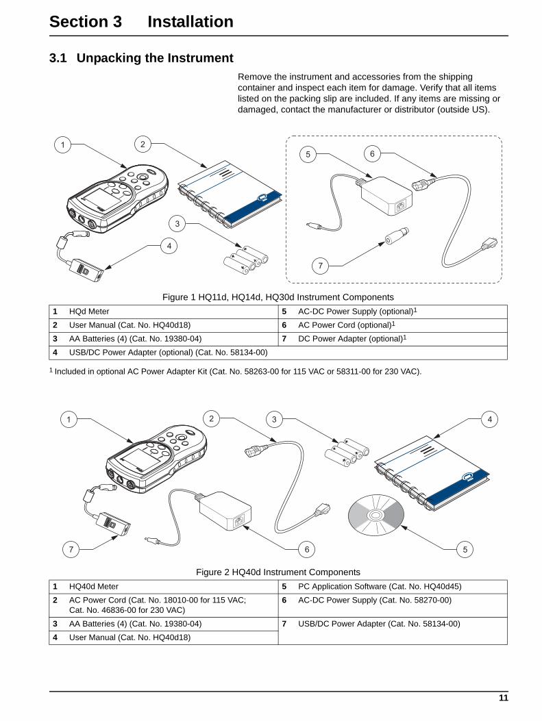
3.1 Unpacking the InstrumentRemove the instrument and accessories from the shipping container and inspect each item for damage. Verify that all items listed on the packing slip are included. If any items are missing or damaged, contact the manufacturer or distributor (outside US).
Figure 1 HQ11d, HQ14d, HQ30d Instrument Components1 HQd Meter 5 AC-DC Power Supply (optional)1
2 User Manual (Cat. No. HQ40d18) 6 AC Power Cord (optional)1
3 AA Batteries (4) (Cat. No. 19380-04) 7 DC Power Adapter (optional)1
4 USB/DC Power Adapter (optional) (Cat. No. 58134-00)
1 Included in optional AC Power Adapter Kit (Cat. No. 58263-00 for 115 VAC or 58311-00 for 230 VAC).
Figure 2 HQ40d Instrument Components1 HQ40d Meter 5 PC Application Software (Cat. No. HQ40d45)
2 AC Power Cord (Cat. No. 18010-00 for 115 VAC; Cat. No. 46836-00 for 230 VAC)
6 AC-DC Power Supply (Cat. No. 58270-00)
3 AA Batteries (4) (Cat. No. 19380-04) 7 USB/DC Power Adapter (Cat. No. 58134-00)
4 User Manual (Cat. No. HQ40d18)
11
Installation
3.2 AC Power and Batteries
DANGERUse only alkaline or nickel metal hydride type batteries in the meter. Other battery types might cause a fire or explosion.
DANGERMake sure that the batteries are installed according to the polarity markings in the meter battery compartment. Failure to correctly install the batteries can result in damage to the meter, fire, or explosion.
DANGERAC mains outlets in wet or potentially wet locations MUST ALWAYS be provided with a Ground Fault Circuit Interrupting (GFCI/GFI) circuit breaker. The AC-DC power adapter provided with this product is not sealed and must not be used on wet benches or in wet locations without GFCI protection.
CAUTIONNever mix battery types in the meter. Use four AA alkaline, or four AA nickel metal hydride batteries.
Important Note: The battery compartment of the meter and the USB/DC power adapter are not waterproof. Use care when operating these devices on a bench in wet environments. Water may infiltrate these devices and eventually cause performance or quality problems. Periodic inspection of the batteries and battery compartment is recommended, if the meter is used in wet environments: remove, clean, and dry the batteries, the interior of the battery compartment, and the battery contacts; then reinsert the batteries and close the compartment cover.
The meter can be battery powered using four AA batteries (alkaline or nickel metal hydride) or by AC power. Connection to AC power requires additional components (section 3.2.2 on page 14).
3.2.1 Battery PowerImportant Note: Rechargeable alkaline or nickel metal hydride batteries may also be used in the meter (do not mix battery types). Batteries are not charged in the meter.
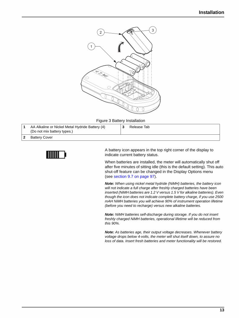
1. Pull the release tab on the battery cover and remove the cover as shown in Figure 3.
2. Insert four AA batteries (alkaline or nickel metal hydride) following polarity markings inside the battery housing.
3. Replace the battery cover.
12
Installation
A battery icon appears in the top right corner of the display to indicate current battery status.
When batteries are installed, the meter will automatically shut off after five minutes of sitting idle (this is the default setting). This auto shut-off feature can be changed in the Display Options menu (see section 9.7 on page 97).
Note: When using nickel metal hydride (NiMH) batteries, the battery icon will not indicate a full charge after freshly charged batteries have been inserted (NiMH batteries are 1.2 V versus 1.5 V for alkaline batteries). Even though the icon does not indicate complete battery charge, if you use 2500 mAH NiMH batteries you will achieve 90% of instrument operation lifetime (before you need to recharge) versus new alkaline batteries.
Note: NiMH batteries self-discharge during storage. If you do not insert freshly charged NiMH batteries, operational lifetime will be reduced from this 90%.
Note: As batteries age, their output voltage decreases. Whenever battery voltage drops below 4-volts, the meter will shut itself down, to assure no loss of data. Insert fresh batteries and meter functionality will be restored.
Figure 3 Battery Installation1 AA Alkaline or Nickel Metal Hydride Battery (4)
(Do not mix battery types.)3 Release Tab
2 Battery Cover
13
Installation
3.2.2 AC PowerAll meters can be powered by AC power using a power supply, adapter, and cord. The HQ40d meter ships with an AC-DC power supply, a USB/DC power adapter, and a power cord (see Figure 6 on page 17). The USB/DC power adaptor allows the meter to transfer data to a computer or flash memory stick (section 3.5 on page 16).
The HQ30d, HQ11d, and HQ14d meters can be powered by AC power using optional AC power adapter kits (Cat. No. 58263-00 for 115 VAC or 58311-00 for 230 VAC). Both kits include an AC-DC power supply, a DC power adapter, and a power cord. (Figure 1 on page 11).
3.3 Turning the Meter On and OffNote: The meter can be operated in several different languages. When the meter is turned on for the first time, the user must select a language before any other meter functions can be accessed. Additionally, the operator is prompted to enter the correct time and date during initial use, and to verify correct time and date whenever the batteries are changed. See section 4.3 on page 22.
Press the power ON/OFF key to turn the meter on. If the meter does not turn on, be sure the batteries are installed properly or that the AC-DC power supply is connected properly to an electrical outlet.
Press the power ON/OFF key to turn the meter off. When batteries are used, the display backlight will turn off after 1 minute, and the meter will automatically turn off after 5 minutes (default settings). These features can be changed in the Meter Options>Display Options>Auto Shut Off/Backlight menus.
3.4 Probe Connection
CAUTIONBEFORE ATTACHING THE PROBE FOR THE FIRST TIME: Set the date and time in the meter before attaching the IntelliCAL probe for its first use. If the meter date and time are incorrect when the probe is installed, the probe will retain this incorrect time stamp for the remainder of its service life, even if the meter time and date have subsequently been corrected.
14

Installation
The HQ11d, HQ14d, and the HQ30d support single connection and display of IntelliCAL™ probes (see Figure 4).
The HQ40d supports dual connection and display of IntelliCAL™ probes (see Figure 5).
Figure 4 Connectors on HQ11d, HQ14d, HQ30d Meters1 USB/DC Power Adapter Port (8-pin) 2 Probe Port (5-pin)
Figure 5 Connectors on HQ40d Meter1 Probe Port (5-pin) 2 USB/DC Power Adapter Port (8-pin)
15
Installation
3.5 Data TransferImportant Note: The battery compartment of the meter and the USB/DC power adapter are not waterproof. Use care when operating these devices on a bench in wet environments. Water may infiltrate these devices and eventually cause performance or quality problems. Periodic inspection of the batteries and battery compartment is recommended, if the meter is used in wet environments: remove, clean, and dry the batteries, the interior of the battery compartment, and the battery contacts; then reinsert the batteries and close the compartment cover.
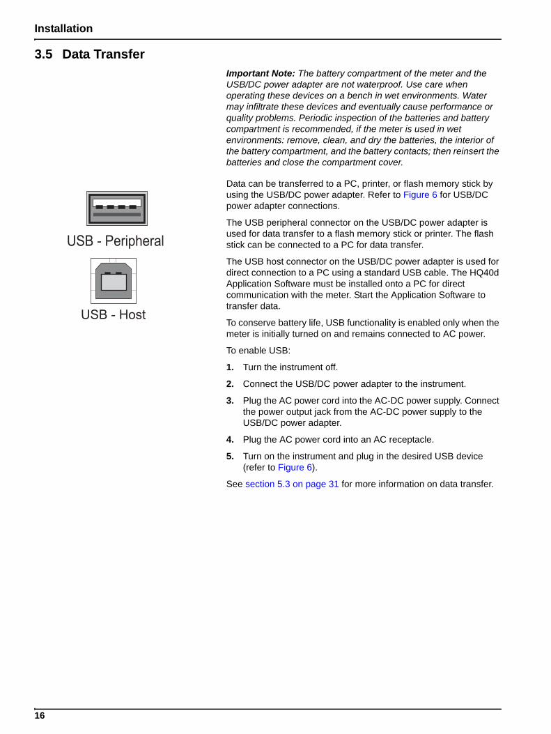
Data can be transferred to a PC, printer, or flash memory stick by using the USB/DC power adapter. Refer to Figure 6 for USB/DC power adapter connections.
The USB peripheral connector on the USB/DC power adapter is used for data transfer to a flash memory stick or printer. The flash stick can be connected to a PC for data transfer.
The USB host connector on the USB/DC power adapter is used for direct connection to a PC using a standard USB cable. The HQ40d Application Software must be installed onto a PC for direct communication with the meter. Start the Application Software to transfer data.
To conserve battery life, USB functionality is enabled only when the meter is initially turned on and remains connected to AC power.
To enable USB:
1. Turn the instrument off.
2. Connect the USB/DC power adapter to the instrument.
3. Plug the AC power cord into the AC-DC power supply. Connect the power output jack from the AC-DC power supply to the USB/DC power adapter.
4. Plug the AC power cord into an AC receptacle.
5. Turn on the instrument and plug in the desired USB device (refer to Figure 6).
See section 5.3 on page 31 for more information on data transfer.
USB - Peripheral
USB - Host
16
Installation
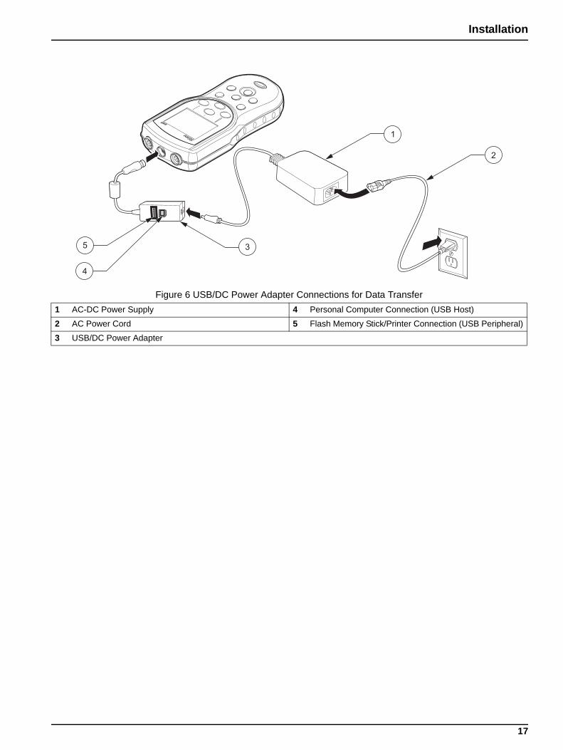
Figure 6 USB/DC Power Adapter Connections for Data Transfer1 AC-DC Power Supply 4 Personal Computer Connection (USB Host)
2 AC Power Cord 5 Flash Memory Stick/Printer Connection (USB Peripheral)
3 USB/DC Power Adapter
17
Section 4 System Start Up
4.1 Basic Start Up Overview1. Install batteries, close the battery compartment door and power
on the meter.
2. Select the language to display on the screen. Refer to section 4.3 on page 22.
3. Set the date and time. Refer to section 4.4 on page 22.
4. Set the Sample and Operator IDs. Refer to section 5.1 on page 25.
5. Connect the probe to the meter.
When an IntelliCAL probe is connected to a HQ30d or HQ40d meter, the meter automatically recognizes the parameter and is ready for use. The HQ11d measures only pH/mV. The HQ14d measures only conductivity, salinity, and total dissolved solids (TDS).
6. Calibrate the probe.
• pH Probe, section 6.1 on page 47
• Conductivity Probe, section 7.1 on page 63
• LDO Probe, section 8.2 on page 79 or use factory-default setting
7. Take a measurement reading.
• pH Probe, section 6.2 on page 49
• Conductivity Probe, section 7.2 on page 64
• LDO Probe, section 8.1 on page 79
8. Run Check Standards (pH and Conductivity only).
• pH Probe, section 6.3 on page 49
• Conductivity Probe, section 7.3 on page 65
9. Set the method.
• pH Probe, section 6.4 on page 51
• Conductivity Probe, section 7.4 on page 66
• LDO Probe, section 8.3 on page 81
10. Modify Meter Options. Refer to Section 9 on page 91.
19
System Start Up
4.2 Meter User Interface and Navigation
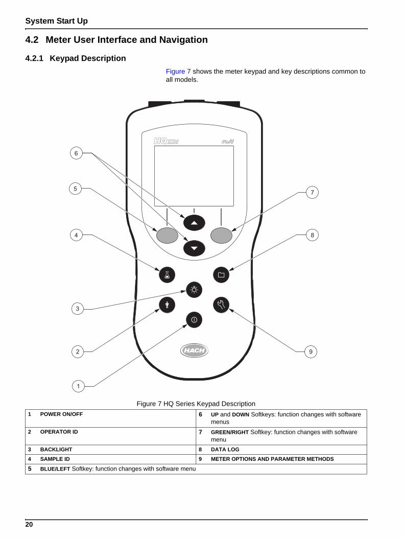
4.2.1 Keypad DescriptionFigure 7 shows the meter keypad and key descriptions common to all models.
Figure 7 HQ Series Keypad Description1 POWER ON/OFF 6 UP and DOWN Softkeys: function changes with software
menus2 OPERATOR ID 7 GREEN/RIGHT Softkey: function changes with software
menu3 BACKLIGHT 8 DATA LOG
4 SAMPLE ID 9 METER OPTIONS AND PARAMETER METHODS
5 BLUE/LEFT Softkey: function changes with software menu
20
System Start Up
4.2.2 Display Description (Single and Dual)
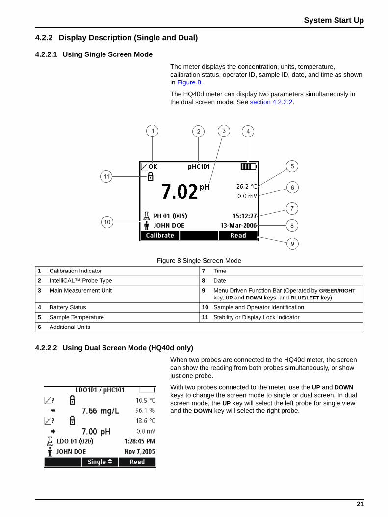
4.2.2.1 Using Single Screen ModeThe meter displays the concentration, units, temperature, calibration status, operator ID, sample ID, date, and time as shown in Figure 8 .
The HQ40d meter can display two parameters simultaneously in the dual screen mode. See section 4.2.2.2.
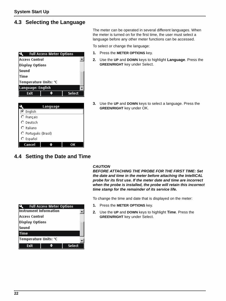
4.2.2.2 Using Dual Screen Mode (HQ40d only)When two probes are connected to the HQ40d meter, the screen can show the reading from both probes simultaneously, or show just one probe.
With two probes connected to the meter, use the UP and DOWN keys to change the screen mode to single or dual screen. In dual screen mode, the UP key will select the left probe for single view and the DOWN key will select the right probe.
Figure 8 Single Screen Mode1 Calibration Indicator 7 Time
2 IntelliCAL™ Probe Type 8 Date
3 Main Measurement Unit 9 Menu Driven Function Bar (Operated by GREEN/RIGHT key, UP and DOWN keys, and BLUE/LEFT key)
4 Battery Status 10 Sample and Operator Identification
5 Sample Temperature 11 Stability or Display Lock Indicator
6 Additional Units
21
System Start Up
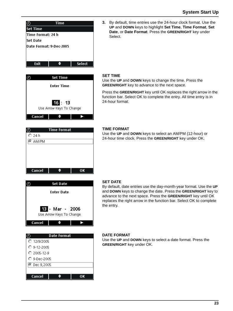
4.3 Selecting the LanguageThe meter can be operated in several different languages. When the meter is turned on for the first time, the user must select a language before any other meter functions can be accessed.
To select or change the language:
1. Press the METER OPTIONS key.
2. Use the UP and DOWN keys to highlight Language. Press the GREEN/RIGHT key under Select.
3. Use the UP and DOWN keys to select a language. Press the GREEN/RIGHT key under OK.
4.4 Setting the Date and Time
CAUTIONBEFORE ATTACHING THE PROBE FOR THE FIRST TIME: Set the date and time in the meter before attaching the IntelliCAL probe for its first use. If the meter date and time are incorrect when the probe is installed, the probe will retain this incorrect time stamp for the remainder of its service life.
To change the time and date that is displayed on the meter:
1. Press the METER OPTIONS key.
2. Use the UP and DOWN keys to highlight Time. Press the GREEN/RIGHT key under Select.
22
System Start Up
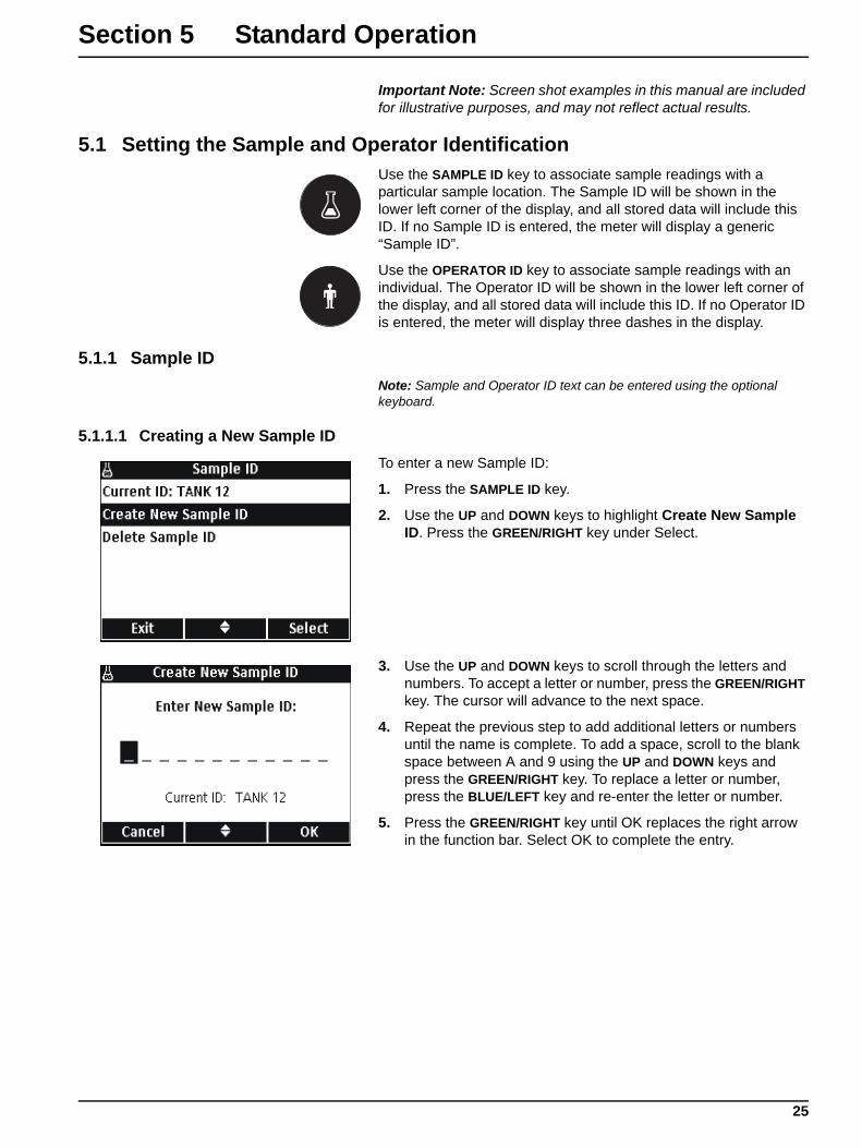
3. By default, time entries use the 24-hour clock format. Use the UP and DOWN keys to highlight Set Time, Time Format, Set Date, or Date Format. Press the GREEN/RIGHT key under Select.
SET TIMEUse the UP and DOWN keys to change the time. Press the GREEN/RIGHT key to advance to the next space.
Press the GREEN/RIGHT key until OK replaces the right arrow in the function bar. Select OK to complete the entry. All time entry is in 24-hour format.
TIME FORMATUse the UP and DOWN keys to select an AM/PM (12-hour) or 24-hour time clock. Press the GREEN/RIGHT key under OK.
SET DATEBy default, date entries use the day-month-year format. Use the UP and DOWN keys to change the date. Press the GREEN/RIGHT key to advance to the next space. Press the GREEN/RIGHT key until OK replaces the right arrow in the function bar. Select OK to complete the entry.
DATE FORMATUse the UP and DOWN keys to select a date format. Press the GREEN/RIGHT key under OK.
23
Section 5 Standard Operation
Important Note: Screen shot examples in this manual are included for illustrative purposes, and may not reflect actual results.
5.1 Setting the Sample and Operator IdentificationUse the SAMPLE ID key to associate sample readings with a particular sample location. The Sample ID will be shown in the lower left corner of the display, and all stored data will include this ID. If no Sample ID is entered, the meter will display a generic “Sample ID”.
Use the OPERATOR ID key to associate sample readings with an individual. The Operator ID will be shown in the lower left corner of the display, and all stored data will include this ID. If no Operator ID is entered, the meter will display three dashes in the display.
5.1.1 Sample IDNote: Sample and Operator ID text can be entered using the optional keyboard.
5.1.1.1 Creating a New Sample IDTo enter a new Sample ID:
1. Press the SAMPLE ID key.
2. Use the UP and DOWN keys to highlight Create New Sample ID. Press the GREEN/RIGHT key under Select.
3. Use the UP and DOWN keys to scroll through the letters and numbers. To accept a letter or number, press the GREEN/RIGHT key. The cursor will advance to the next space.
4. Repeat the previous step to add additional letters or numbers until the name is complete. To add a space, scroll to the blank space between A and 9 using the UP and DOWN keys and press the GREEN/RIGHT key. To replace a letter or number, press the BLUE/LEFT key and re-enter the letter or number.
5. Press the GREEN/RIGHT key until OK replaces the right arrow in the function bar. Select OK to complete the entry.
25
Standard Operation
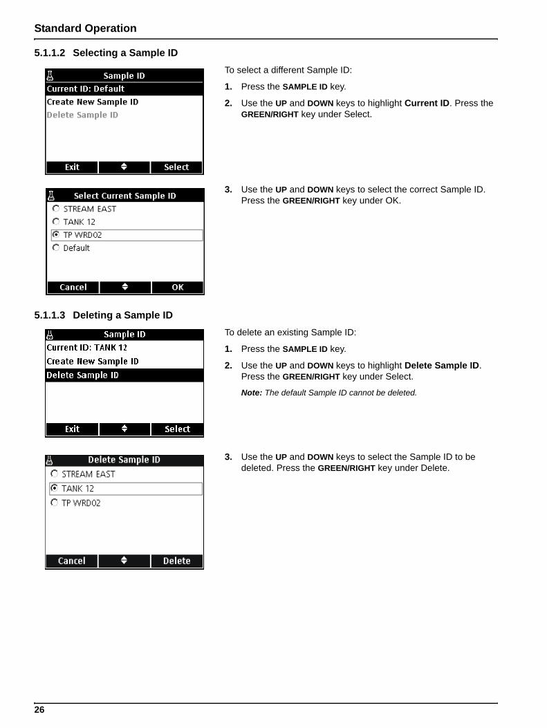
5.1.1.2 Selecting a Sample IDTo select a different Sample ID:
1. Press the SAMPLE ID key.
2. Use the UP and DOWN keys to highlight Current ID. Press the GREEN/RIGHT key under Select.
3. Use the UP and DOWN keys to select the correct Sample ID. Press the GREEN/RIGHT key under OK.
5.1.1.3 Deleting a Sample IDTo delete an existing Sample ID:
1. Press the SAMPLE ID key.
2. Use the UP and DOWN keys to highlight Delete Sample ID. Press the GREEN/RIGHT key under Select.
Note: The default Sample ID cannot be deleted.
3. Use the UP and DOWN keys to select the Sample ID to be deleted. Press the GREEN/RIGHT key under Delete.
26
Standard Operation
5.1.2 Operator ID
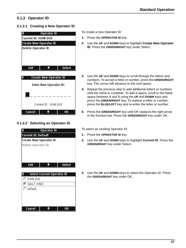
5.1.2.1 Creating a New Operator IDTo create a new Operator ID:
1. Press the OPERATOR ID key.
2. Use the UP and DOWN keys to highlight Create New Operator ID. Press the GREEN/RIGHT key under Select.
3. Use the UP and DOWN keys to scroll through the letters and numbers. To accept a letter or number, press the GREEN/RIGHT key. The cursor will advance to the next space.
4. Repeat the previous step to add additional letters or numbers until the name is complete. To add a space, scroll to the blank space between A and 9 using the UP and DOWN keys and press the GREEN/RIGHT key. To replace a letter or number, press the BLUE/LEFT key and re-enter the letter or number.
5. Press the GREEN/RIGHT key until OK replaces the right arrow in the function bar. Press the GREEN/RIGHT key under OK.
5.1.2.2 Selecting an Operator IDTo select an existing Operator ID:
1. Press the OPERATOR ID key.
2. Use the UP and DOWN keys to highlight Current ID. Press the GREEN/RIGHT key under Select.
3. Use the UP and DOWN keys to select the Operator ID. Press the GREEN/RIGHT key under OK.
27
Standard Operation
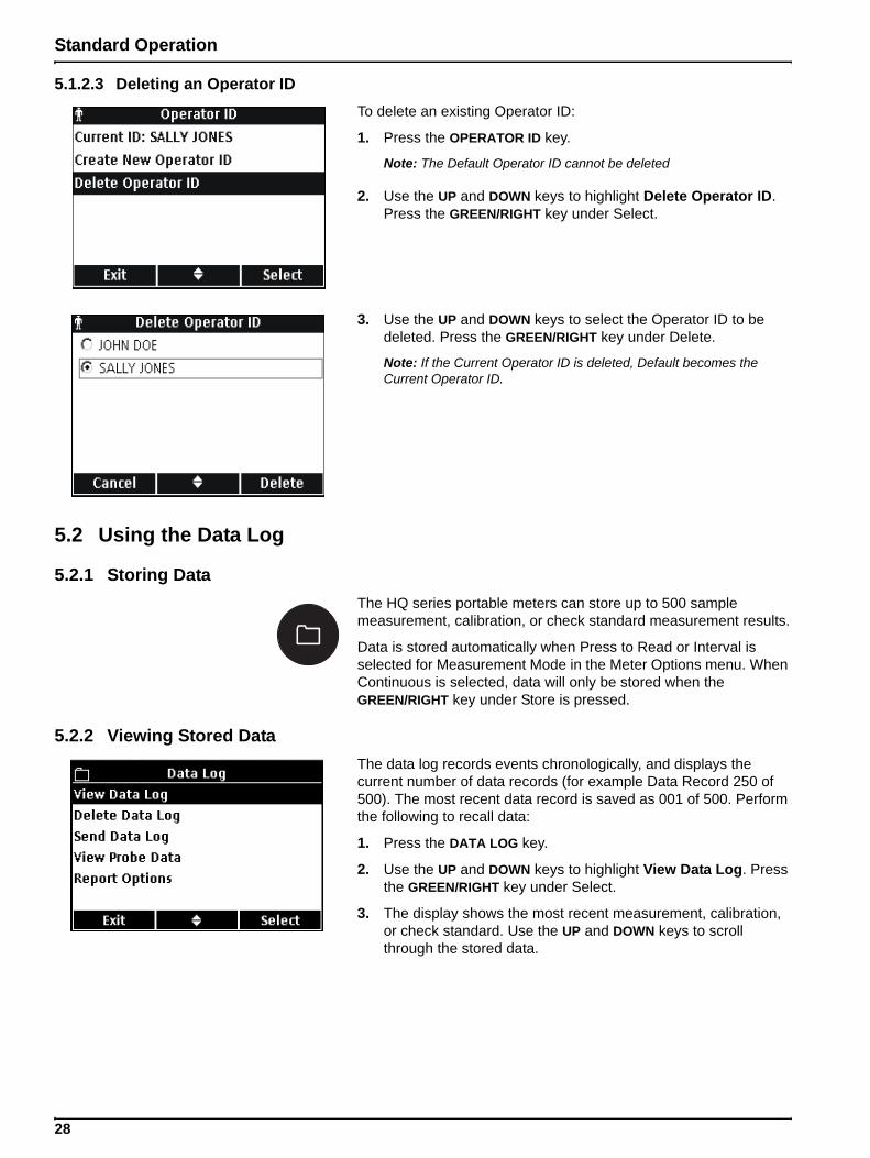
5.1.2.3 Deleting an Operator IDTo delete an existing Operator ID:
1. Press the OPERATOR ID key.
Note: The Default Operator ID cannot be deleted
2. Use the UP and DOWN keys to highlight Delete Operator ID. Press the GREEN/RIGHT key under Select.
3. Use the UP and DOWN keys to select the Operator ID to be deleted. Press the GREEN/RIGHT key under Delete.
Note: If the Current Operator ID is deleted, Default becomes the Current Operator ID.
5.2 Using the Data Log
5.2.1 Storing DataThe HQ series portable meters can store up to 500 sample measurement, calibration, or check standard measurement results.
Data is stored automatically when Press to Read or Interval is selected for Measurement Mode in the Meter Options menu. When Continuous is selected, data will only be stored when the GREEN/RIGHT key under Store is pressed.
5.2.2 Viewing Stored DataThe data log records events chronologically, and displays the current number of data records (for example Data Record 250 of 500). The most recent data record is saved as 001 of 500. Perform the following to recall data:
1. Press the DATA LOG key.
2. Use the UP and DOWN keys to highlight View Data Log. Press the GREEN/RIGHT key under Select.
3. The display shows the most recent measurement, calibration, or check standard. Use the UP and DOWN keys to scroll through the stored data.
28
Standard Operation
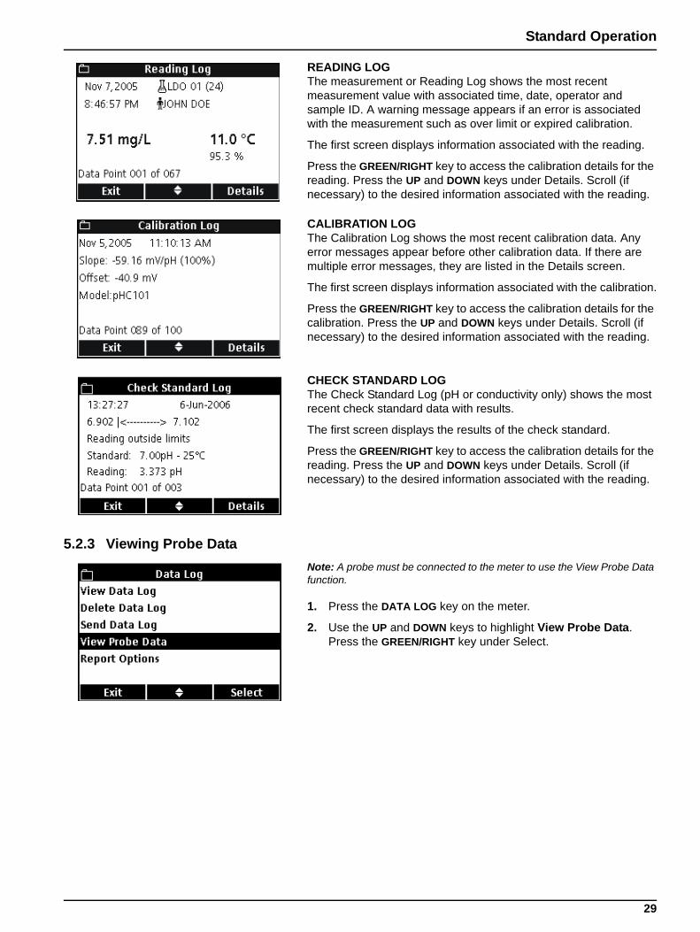
READING LOGThe measurement or Reading Log shows the most recent measurement value with associated time, date, operator and sample ID. A warning message appears if an error is associated with the measurement such as over limit or expired calibration.
The first screen displays information associated with the reading.
Press the GREEN/RIGHT key to access the calibration details for the reading. Press the UP and DOWN keys under Details. Scroll (if necessary) to the desired information associated with the reading.
CALIBRATION LOGThe Calibration Log shows the most recent calibration data. Any error messages appear before other calibration data. If there are multiple error messages, they are listed in the Details screen.
The first screen displays information associated with the calibration.
Press the GREEN/RIGHT key to access the calibration details for the calibration. Press the UP and DOWN keys under Details. Scroll (if necessary) to the desired information associated with the reading.
CHECK STANDARD LOGThe Check Standard Log (pH or conductivity only) shows the most recent check standard data with results.
The first screen displays the results of the check standard.
Press the GREEN/RIGHT key to access the calibration details for the reading. Press the UP and DOWN keys under Details. Scroll (if necessary) to the desired information associated with the reading.
5.2.3 Viewing Probe DataNote: A probe must be connected to the meter to use the View Probe Data function.
1. Press the DATA LOG key on the meter.
2. Use the UP and DOWN keys to highlight View Probe Data. Press the GREEN/RIGHT key under Select.
29

Standard Operation
3. If only one probe is connected, proceed to Step 4. If two probes are connected (HQ40d only), the connected probes will be displayed. Use the UP and DOWN keys to highlight the probe. Press the GREEN/RIGHT key under Select.
4. Use the UP and DOWN keys to highlight one of the selections for Probe Data. Press the GREEN/RIGHT key under Select.
5.2.4 Deleting DataData will be automatically deleted when the data log is full on a first in first out basis (oldest data deleted first).
Data can be deleted manually when Access Control is off, or when a valid password is entered.
1. Press the DATA LOG key.
2. Use the UP and DOWN keys to highlight Delete Data Log. Press the GREEN/RIGHT key under Select.
3. The display will show “Delete All Data?”. Press the GREEN/RIGHT key under Select to delete all stored data.
30
Standard Operation
5.3 Transferring DataData can be transferred to a printer, flash memory stick, or computer (PC) using the USB connection on the USB/DC power adapter. The meter must be powered on after connection to AC power for data transfer to occur.
Note: If the response time is slow when transferring data, reformat the flash memory stick or computer to use the file allocation table (FAT) format.
5.3.1 Transferring Data OptionsData that is sent to a printer can be configured to contain one, two, or three lines of information (Basic, Advanced, or Total Reports). Data that is transferred to a computer or flash memory stick can be configured to include or omit a column header row.
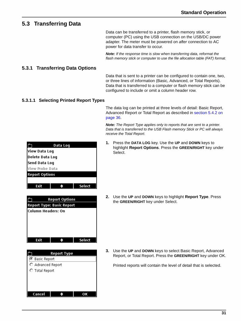
5.3.1.1 Selecting Printed Report TypesThe data log can be printed at three levels of detail: Basic Report, Advanced Report or Total Report as described in section 5.4.2 on page 36.
Note: The Report Type applies only to reports that are sent to a printer. Data that is transferred to the USB Flash memory Stick or PC will always receive the Total Report.
1. Press the DATA LOG key. Use the UP and DOWN keys to highlight Report Options. Press the GREEN/RIGHT key under Select.
2. Use the UP and DOWN keys to highlight Report Type. Press the GREEN/RIGHT key under Select.
3. Use the UP and DOWN keys to select Basic Report, Advanced Report, or Total Report. Press the GREEN/RIGHT key under OK.
Printed reports will contain the level of detail that is selected.
31

Standard Operation
5.3.1.2 Including Column Headers in Data FilesThe HQd meters include a row of column headings whenever data is stored in the meter. This header contains descriptions of the data so that the downloaded data is easily recognizable (section 5.6 on page 42). The header information is sent to a USB flash memory stick and/or PC when the column headers option is on.
Note: Column Headers applies only to data that is sent to a USB Flash memory Stick or PC.
The column headers option is on by default and should be left on for most users. If an application or post-processing method is used that is incompatible with the headers, the column headers can be turned off.
Note: If the column headers option is changed from off to on, or if the language setting is changed, a column header row will appear in the data table at the point where the change took place.
To turn column headers off or on:
1. Press the DATA LOG key. Use the UP and DOWN keys to highlight Report Options. Press the GREEN/RIGHT key under Select.
2. Use the UP and DOWN keys to highlight Column Headers. Press the GREEN/RIGHT key under Select.
3. Use the UP and DOWN keys to select On or Off. Press the GREEN/RIGHT key under OK.
32
Standard Operation
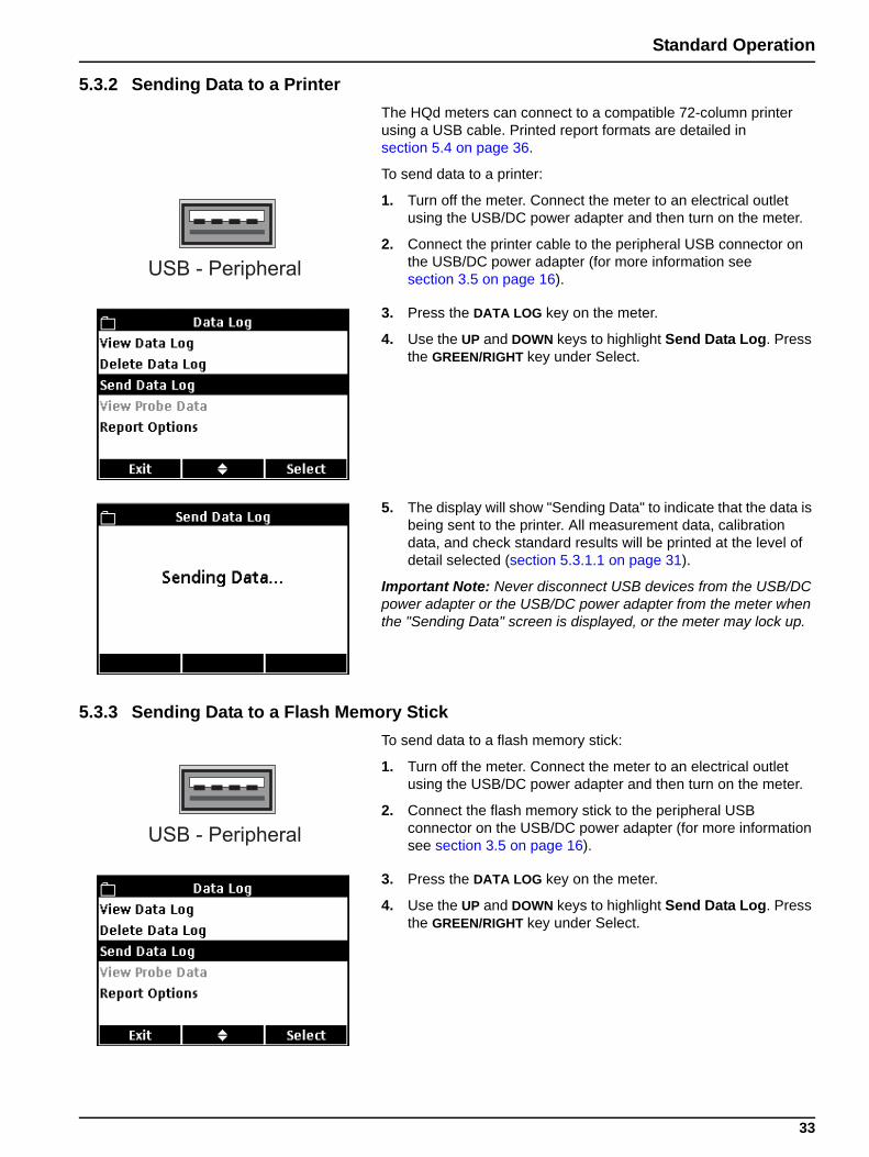
5.3.2 Sending Data to a PrinterThe HQd meters can connect to a compatible 72-column printer using a USB cable. Printed report formats are detailed in section 5.4 on page 36.
To send data to a printer:
1. Turn off the meter. Connect the meter to an electrical outlet using the USB/DC power adapter and then turn on the meter.
2. Connect the printer cable to the peripheral USB connector on the USB/DC power adapter (for more information see section 3.5 on page 16).
3. Press the DATA LOG key on the meter.
4. Use the UP and DOWN keys to highlight Send Data Log. Press the GREEN/RIGHT key under Select.
5. The display will show "Sending Data" to indicate that the data is being sent to the printer. All measurement data, calibration data, and check standard results will be printed at the level of detail selected (section 5.3.1.1 on page 31).
Important Note: Never disconnect USB devices from the USB/DC power adapter or the USB/DC power adapter from the meter when the "Sending Data" screen is displayed, or the meter may lock up.
5.3.3 Sending Data to a Flash Memory StickTo send data to a flash memory stick:
1. Turn off the meter. Connect the meter to an electrical outlet using the USB/DC power adapter and then turn on the meter.
2. Connect the flash memory stick to the peripheral USB connector on the USB/DC power adapter (for more information see section 3.5 on page 16).
3. Press the DATA LOG key on the meter.
4. Use the UP and DOWN keys to highlight Send Data Log. Press the GREEN/RIGHT key under Select.
USB - Peripheral
USB - Peripheral
33
Standard Operation
5. The display will show "Sending Data" to indicate that the data is being stored on the flash memory stick. All measurement data, calibration data, and check standard results will be stored on the memory stick in a text (.txt) file format.
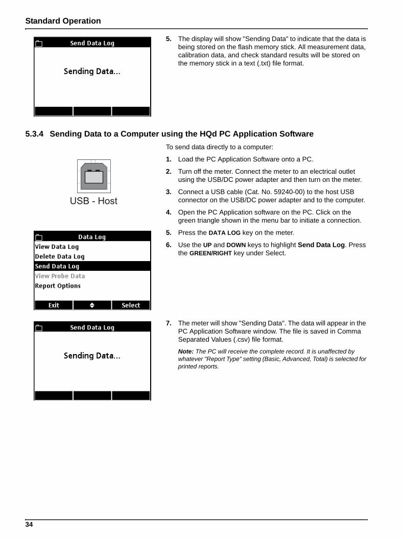
5.3.4 Sending Data to a Computer using the HQd PC Application SoftwareTo send data directly to a computer:
1. Load the PC Application Software onto a PC.
2. Turn off the meter. Connect the meter to an electrical outlet using the USB/DC power adapter and then turn on the meter.
3. Connect a USB cable (Cat. No. 59240-00) to the host USB connector on the USB/DC power adapter and to the computer.
4. Open the PC Application software on the PC. Click on the green triangle shown in the menu bar to initiate a connection.
5. Press the DATA LOG key on the meter.
6. Use the UP and DOWN keys to highlight Send Data Log. Press the GREEN/RIGHT key under Select.
7. The meter will show "Sending Data". The data will appear in the PC Application Software window. The file is saved in Comma Separated Values (.csv) file format.
Note: The PC will receive the complete record. It is unaffected by whatever "Report Type" setting (Basic, Advanced, Total) is selected for printed reports.
USB - Host
34
Standard Operation
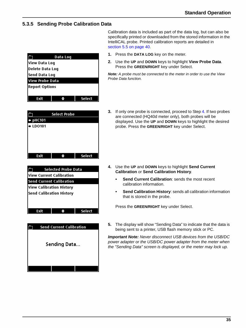
5.3.5 Sending Probe Calibration DataCalibration data is included as part of the data log, but can also be specifically printed or downloaded from the stored information in the IntelliCAL probe. Printed calibration reports are detailed in section 5.5 on page 40.
1. Press the DATA LOG key on the meter.
2. Use the UP and DOWN keys to highlight View Probe Data. Press the GREEN/RIGHT key under Select.
Note: A probe must be connected to the meter in order to use the View Probe Data function.
3. If only one probe is connected, proceed to Step 4. If two probes are connected (HQ40d meter only), both probes will be displayed. Use the UP and DOWN keys to highlight the desired probe. Press the GREEN/RIGHT key under Select.
4. Use the UP and DOWN keys to highlight Send Current Calibration or Send Calibration History.
• Send Current Calibration: sends the most recent calibration information.
• Send Calibration History: sends all calibration information that is stored in the probe.
Press the GREEN/RIGHT key under Select.
5. The display will show “Sending Data” to indicate that the data is being sent to a printer, USB flash memory stick or PC.
Important Note: Never disconnect USB devices from the USB/DC power adapter or the USB/DC power adapter from the meter when the "Sending Data" screen is displayed, or the meter may lock up.
35
Standard Operation
5.4 Viewing Printed Data Log ReportsWhen the data log is sent to a printer (section 5.3.2 on page 33), the printed report contains all stored sample data, check standard data, and calibration information.
Note: All error messages will print at the end of each report option selected (Basic Report, Advanced Report, or Total Report).
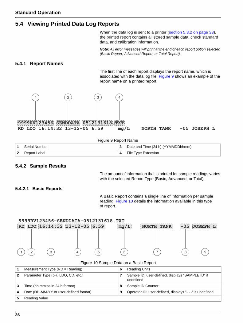
5.4.1 Report NamesThe first line of each report displays the report name, which is associated with the data log file. Figure 9 shows an example of the report name on a printed report.
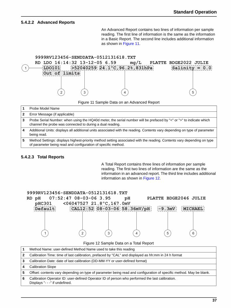
5.4.2 Sample ResultsThe amount of information that is printed for sample readings varies with the selected Report Type (Basic, Advanced, or Total).
5.4.2.1 Basic ReportsA Basic Report contains a single line of information per sample reading. Figure 10 details the information available in this type of report.
Figure 9 Report Name1 Serial Number 3 Date and Time (24 h) (YYMMDDhhmm)
2 Report Label 4 File Type Extension
Figure 10 Sample Data on a Basic Report1 Measurement Type (RD = Reading) 6 Reading Units
2 Parameter Type (pH, LDO, CD, etc.) 7 Sample ID: user-defined, displays "SAMPLE ID" if undefined
3 Time (hh:mm:ss in 24 h format) 8 Sample ID Counter
4 Date (DD-MM-YY or user-defined format) 9 Operator ID: user-defined, displays "- - -" if undefined
5 Reading Value
36
Standard Operation
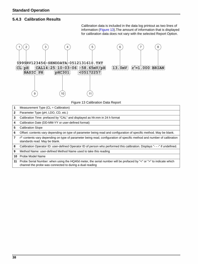
5.4.2.2 Advanced ReportsAn Advanced Report contains two lines of information per sample reading. The first line of information is the same as the information in a Basic Report. The second line includes additional information as shown in Figure 11.
5.4.2.3 Total ReportsA Total Report contains three lines of information per sample reading. The first two lines of information are the same as the information in an advanced report. The third line includes additional information as shown in Figure 12.
Figure 11 Sample Data on an Advanced Report1 Probe Model Name
2 Error Message (if applicable)
3 Probe Serial Number: when using the HQ40d meter, the serial number will be prefaced by "<" or ">" to indicate which channel the probe was connected to during a dual reading.
4 Additional Units: displays all additional units associated with the reading. Contents vary depending on type of parameter being read.
5 Method Settings: displays highest-priority method setting associated with the reading. Contents vary depending on type of parameter being read and configuration of specific method.
Figure 12 Sample Data on a Total Report1 Method Name: user-defined Method Name used to take this reading
2 Calibration Time: time of last calibration, prefaced by "CAL" and displayed as hh:mm in 24 h format
3 Calibration Date: date of last calibration (DD-MM-YY or user-defined format)
4 Calibration Slope
5 Offset: contents vary depending on type of parameter being read and configuration of specific method. May be blank.
6 Calibration Operator ID: user-defined Operator ID of person who performed the last calibration. Displays "- - -" if undefined.
37
Standard Operation
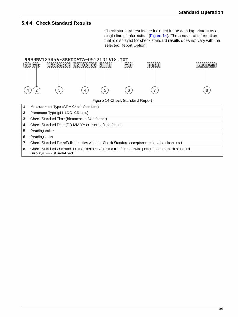
5.4.3 Calibration ResultsCalibration data is included in the data log printout as two lines of information (Figure 13).The amount of information that is displayed for calibration data does not vary with the selected Report Option.
Figure 13 Calibration Data Report1 Measurement Type (CL = Calibration)
2 Parameter Type (pH, LDO, CD, etc.)
3 Calibration Time: prefaced by "CAL" and displayed as hh:mm in 24 h format
4 Calibration Date (DD-MM-YY or user-defined format)
5 Calibration Slope
6 Offset: contents vary depending on type of parameter being read and configuration of specific method. May be blank.
7 r2: contents vary depending on type of parameter being read, configuration of specific method and number of calibration standards read. May be blank.
8 Calibration Operator ID: user-defined Operator ID of person who performed this calibration. Displays "- - -" if undefined.
9 Method Name: user-defined Method Name used to take this reading
10 Probe Model Name
11 Probe Serial Number: when using the HQ40d meter, the serial number will be prefaced by "<" or ">" to indicate which channel the probe was connected to during a dual reading
38
Standard Operation
5.4.4 Check Standard ResultsCheck standard results are included in the data log printout as a single line of information (Figure 14). The amount of information that is displayed for check standard results does not vary with the selected Report Option.
Figure 14 Check Standard Report1 Measurement Type (ST = Check Standard)
2 Parameter Type (pH, LDO, CD, etc.)
3 Check Standard Time (hh:mm:ss in 24 h format)
4 Check Standard Date (DD-MM-YY or user-defined format)
5 Reading Value
6 Reading Units
7 Check Standard Pass/Fail: identifies whether Check Standard acceptance criteria has been met
8 Check Standard Operator ID: user-defined Operator ID of person who performed the check standard. Displays "- - -" if undefined.
39
Standard Operation
5.5 Viewing Printed Calibration ReportsA report can be printed for current calibration information or calibration history as described in section 5.3.5 on page 35.
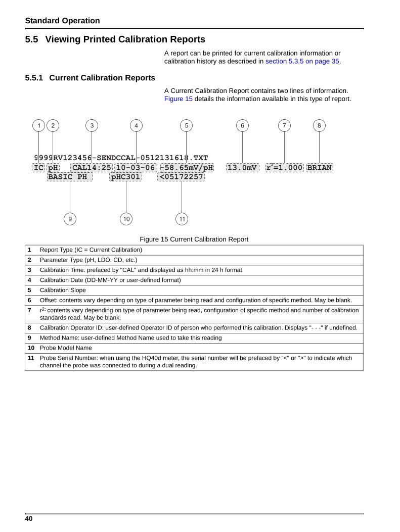
5.5.1 Current Calibration ReportsA Current Calibration Report contains two lines of information. Figure 15 details the information available in this type of report.
Figure 15 Current Calibration Report1 Report Type (IC = Current Calibration)
2 Parameter Type (pH, LDO, CD, etc.)
3 Calibration Time: prefaced by "CAL" and displayed as hh:mm in 24 h format
4 Calibration Date (DD-MM-YY or user-defined format)
5 Calibration Slope
6 Offset: contents vary depending on type of parameter being read and configuration of specific method. May be blank.
7 r2: contents vary depending on type of parameter being read, configuration of specific method and number of calibration standards read. May be blank.
8 Calibration Operator ID: user-defined Operator ID of person who performed this calibration. Displays "- - -" if undefined.
9 Method Name: user-defined Method Name used to take this reading
10 Probe Model Name
11 Probe Serial Number: when using the HQ40d meter, the serial number will be prefaced by "<" or ">" to indicate which channel the probe was connected to during a dual reading.
40

Standard Operation
5.5.2 Calibration History ReportsA Calibration History Report contains two lines of information per calibration. Figure 16 details the information available in this type of report.
Figure 16 Calibration History Report1 Report Type (CH = Calibration History)
2 Parameter Type (pH, LDO, CD, etc.)
3 Calibration Time: prefaced by "CAL" and displayed as hh:mm in 24 h format
4 Calibration Date (DD-MM-YY or user-defined format)
5 Calibration Slope
6 Offset: contents vary depending on type of parameter being read and configuration of specific method. May be blank.
7 Probe Model Name
8 Probe Serial Number: when using the HQ40d meter, the serial number will be prefaced by "<" or ">" to indicate which channel the probe was connected to during a dual reading.
41
Standard Operation
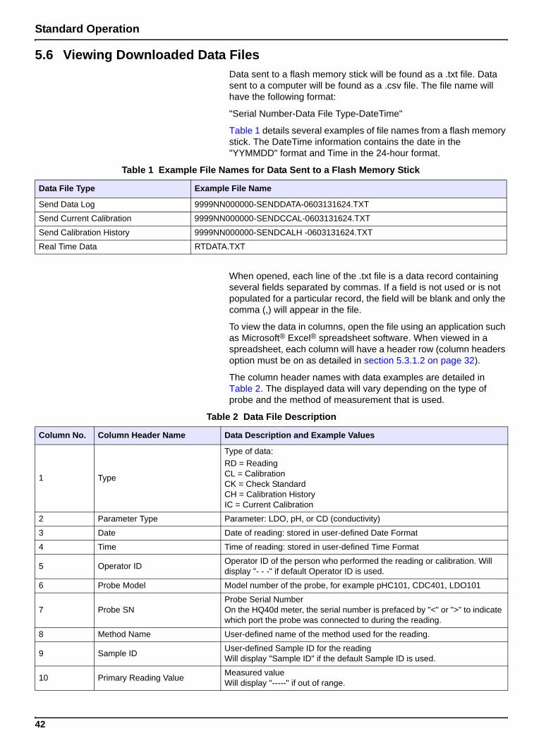
5.6 Viewing Downloaded Data FilesData sent to a flash memory stick will be found as a .txt file. Data sent to a computer will be found as a .csv file. The file name will have the following format:
"Serial Number-Data File Type-DateTime"
Table 1 details several examples of file names from a flash memory stick. The DateTime information contains the date in the "YYMMDD" format and Time in the 24-hour format.
When opened, each line of the .txt file is a data record containing several fields separated by commas. If a field is not used or is not populated for a particular record, the field will be blank and only the comma (,) will appear in the file.
To view the data in columns, open the file using an application such as Microsoft® Excel® spreadsheet software. When viewed in a spreadsheet, each column will have a header row (column headers option must be on as detailed in section 5.3.1.2 on page 32).
The column header names with data examples are detailed in Table 2. The displayed data will vary depending on the type of probe and the method of measurement that is used.
Table 1 Example File Names for Data Sent to a Flash Memory Stick
Data File Type Example File Name
Send Data Log 9999NN000000-SENDDATA-0603131624.TXT
Send Current Calibration 9999NN000000-SENDCCAL-0603131624.TXT
Send Calibration History 9999NN000000-SENDCALH -0603131624.TXT
Real Time Data RTDATA.TXT
Table 2 Data File Description
Column No. Column Header Name Data Description and Example Values
1 Type
Type of data:RD = ReadingCL = CalibrationCK = Check StandardCH = Calibration HistoryIC = Current Calibration
2 Parameter Type Parameter: LDO, pH, or CD (conductivity)
3 Date Date of reading: stored in user-defined Date Format
4 Time Time of reading: stored in user-defined Time Format
5 Operator ID Operator ID of the person who performed the reading or calibration. Will display "- - -" if default Operator ID is used.
6 Probe Model Model number of the probe, for example pHC101, CDC401, LDO101
7 Probe SNProbe Serial Number On the HQ40d meter, the serial number is prefaced by "<" or ">" to indicate which port the probe was connected to during the reading.
8 Method Name User-defined name of the method used for the reading.
9 Sample ID User-defined Sample ID for the readingWill display "Sample ID" if the default Sample ID is used.
10 Primary Reading Value Measured valueWill display "-----" if out of range.
42
Standard Operation
11 Primary Reading Units Measurement units defined for method, for example pH or mS/cm
12 Supp Reading 1 First Supplemental Reading if applicable, for example temperature.
13 Supp Units 1 Units for First Supplemental Reading, if applicable.
14 Supp Reading 2 Second Supplemental Reading, if applicable (example: “mV” for pH
15 Supp Units 2 Units for Second Supplemental Reading, if applicable.
16 Supp Reading 3 Third Supplemental Reading, if applicable.
17 Supp Units 3 Units for Third Supplemental Reading, if applicable.
18 Reading Setting 1
Any settings that affect the reading, for example "NaCl/Non-Linear"19 Reading Setting 2
20 Reading Setting 3
21 Reading Setting 4
22 Reading Message 1
Any message (warning, information, etc.) that was displayed during the measurement, for example "Out of limits".
23 Reading Message 2
24 Reading Message 3
25 Reading Message 4
26 Check Std ValueValue of the standard that was used to verify accuracy, for example:7.00pH–25ºC (pH, temp-compensated)7.01pH (pH, custom)
27 Check Std Units Check standard units, for example µS/cm.Note: pH is not displayed here as it is included in the previous column.
28 Check Std Graph Bar-graph showing the measurement in relation to the acceptance limitsExample: “6.901 <-----|----> 7.101"
29 Check Std Status Status of the check standard readingExample: "Reading within limits", "Reading outside limits"
30 Calibration Status OK = current calibration is valid? = calibration has expired
31 Cal Date Date of Calibration Reading: stored in user-defined Date Format
32 Cal Time Time of Calibration Reading: stored in user-defined Time Format
33 Cal Operator ID The Operator ID specified when the probe was calibrated Will display "- - -" if undefined.
34 Cal Slope Name Slope (pH or LDO) or Cell Constant (conductivity)
35 Cal Slope The slope value for the calibration
36 Cal Slope Aux Used by pH to give the percent of nominal slope
37 Cal Slope Units Units of the calibration slope Example: “mV/pH” for pH
38 Cal Offset Calibration offset value
39 Cal Offset Units Calibration offset units Example: "mV" for pH
40 Cal r2 Unitless calibration correlation coefficient
41 Cal Number of Std’s Number of standards used during calibration, for example 5. May be blank depending on Record Type, Parameter Type and Method Settings.
42 Cal Std 1 Known value of the first calibration standard
43 Cal Std 1 Units Units of the first calibration standard
44 Cal Std 1 Primary Value Measured value of the first calibration standard
45 Cal Std 1 Primary Units Associated units for the calibration measurement
46 Cal Std 1 Supp Value Value of supplemental measurement, for example temperature
Table 2 Data File Description
Column No. Column Header Name Data Description and Example Values
43
Standard Operation
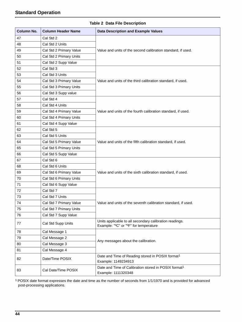
47 Cal Std 2
Value and units of the second calibration standard, if used.
48 Cal Std 2 Units
49 Cal Std 2 Primary Value
50 Cal Std 2 Primary Units
51 Cal Std 2 Supp Value
52 Cal Std 3
Value and units of the third calibration standard, if used.
53 Cal Std 3 Units
54 Cal Std 3 Primary Value
55 Cal Std 3 Primary Units
56 Cal Std 3 Supp value
57 Cal Std 4
Value and units of the fourth calibration standard, if used.
58 Cal Std 4 Units
59 Cal Std 4 Primary Value
60 Cal Std 4 Primary Units
61 Cal Std 4 Supp Value
62 Cal Std 5
Value and units of the fifth calibration standard, if used.
63 Cal Std 5 Units
64 Cal Std 5 Primary Value
65 Cal Std 5 Primary Units
66 Cal Std 5 Supp Value
67 Cal Std 6
Value and units of the sixth calibration standard, if used.
68 Cal Std 6 Units
69 Cal Std 6 Primary Value
70 Cal Std 6 Primary Units
71 Cal Std 6 Supp Value
72 Cal Std 7
Value and units of the seventh calibration standard, if used.
73 Cal Std 7 Units
74 Cal Std 7 Primary Value
75 Cal Std 7 Primary Units
76 Cal Std 7 Supp Value
77 Cal Std Supp Units Units applicable to all secondary calibration readings. Example: "ºC" or "ºF" for temperature
78 Cal Message 1
Any messages about the calibration.79 Cal Message 2
80 Cal Message 3
81 Cal Message 4
82 Date/Time POSIXDate and Time of Reading stored in POSIX format1 Example: 1149234913
83 Cal Date/Time POSIXDate and Time of Calibration stored in POSIX format1
Example: 1111320348
1 POSIX date format expresses the date and time as the number of seconds from 1/1/1970 and is provided for advanced post-processing applications.
Table 2 Data File Description
Column No. Column Header Name Data Description and Example Values
44
Standard Operation
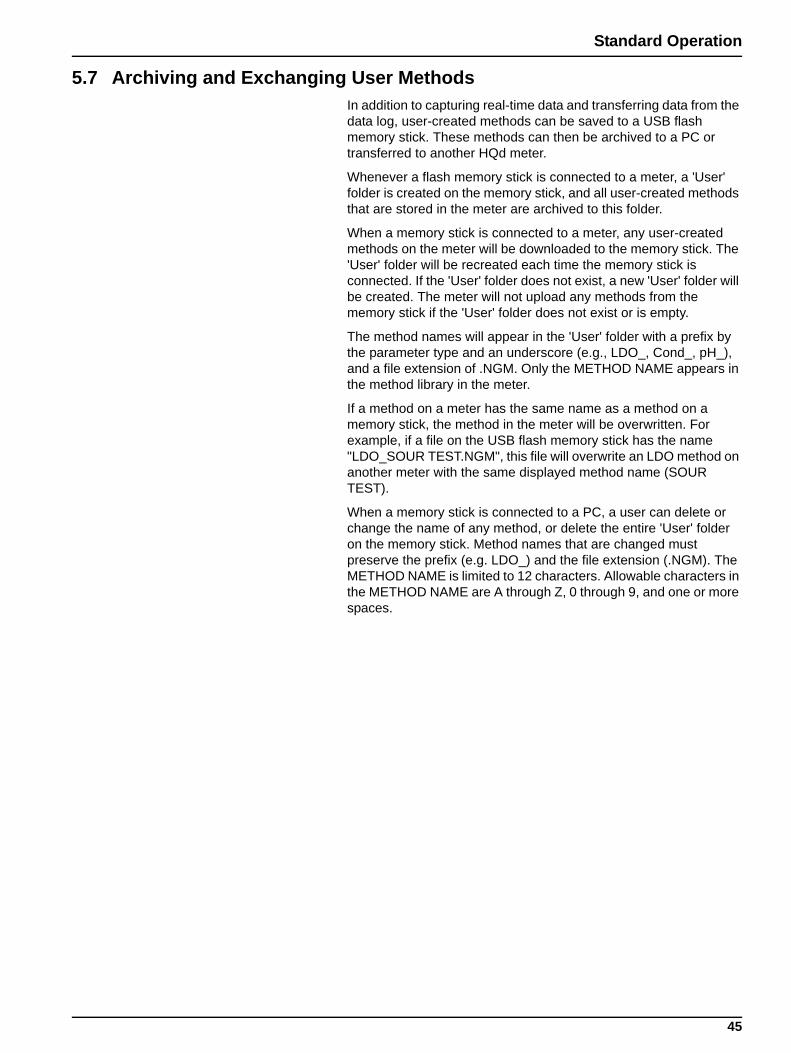
5.7 Archiving and Exchanging User MethodsIn addition to capturing real-time data and transferring data from the data log, user-created methods can be saved to a USB flash memory stick. These methods can then be archived to a PC or transferred to another HQd meter.
Whenever a flash memory stick is connected to a meter, a 'User' folder is created on the memory stick, and all user-created methods that are stored in the meter are archived to this folder.
When a memory stick is connected to a meter, any user-created methods on the meter will be downloaded to the memory stick. The 'User' folder will be recreated each time the memory stick is connected. If the 'User' folder does not exist, a new 'User' folder will be created. The meter will not upload any methods from the memory stick if the 'User' folder does not exist or is empty.
The method names will appear in the 'User' folder with a prefix by the parameter type and an underscore (e.g., LDO_, Cond_, pH_), and a file extension of .NGM. Only the METHOD NAME appears in the method library in the meter.
If a method on a meter has the same name as a method on a memory stick, the method in the meter will be overwritten. For example, if a file on the USB flash memory stick has the name "LDO_SOUR TEST.NGM", this file will overwrite an LDO method on another meter with the same displayed method name (SOUR TEST).
When a memory stick is connected to a PC, a user can delete or change the name of any method, or delete the entire 'User' folder on the memory stick. Method names that are changed must preserve the prefix (e.g. LDO_) and the file extension (.NGM). The METHOD NAME is limited to 12 characters. Allowable characters in the METHOD NAME are A through Z, 0 through 9, and one or more spaces.
45
Section 6 pH Operation and Methods
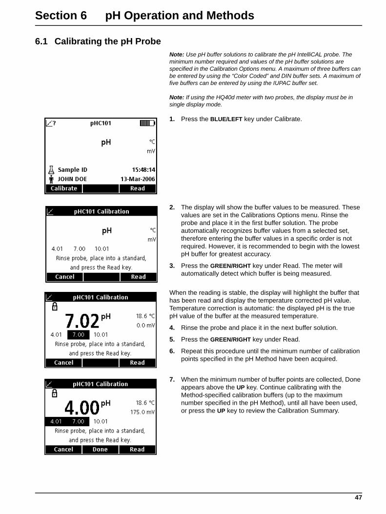
6.1 Calibrating the pH ProbeNote: Use pH buffer solutions to calibrate the pH IntelliCAL probe. The minimum number required and values of the pH buffer solutions are specified in the Calibration Options menu. A maximum of three buffers can be entered by using the “Color Coded” and DIN buffer sets. A maximum of five buffers can be entered by using the IUPAC buffer set.
Note: If using the HQ40d meter with two probes, the display must be in single display mode.
1. Press the BLUE/LEFT key under Calibrate.
2. The display will show the buffer values to be measured. These values are set in the Calibrations Options menu. Rinse the probe and place it in the first buffer solution. The probe automatically recognizes buffer values from a selected set, therefore entering the buffer values in a specific order is not required. However, it is recommended to begin with the lowest pH buffer for greatest accuracy.
3. Press the GREEN/RIGHT key under Read. The meter will automatically detect which buffer is being measured.
When the reading is stable, the display will highlight the buffer that has been read and display the temperature corrected pH value. Temperature correction is automatic: the displayed pH is the true pH value of the buffer at the measured temperature.
4. Rinse the probe and place it in the next buffer solution.
5. Press the GREEN/RIGHT key under Read.
6. Repeat this procedure until the minimum number of calibration points specified in the pH Method have been acquired.
7. When the minimum number of buffer points are collected, Done appears above the UP key. Continue calibrating with the Method-specified calibration buffers (up to the maximum number specified in the pH Method), until all have been used, or press the UP key to review the Calibration Summary.
47
pH Operation and Methods
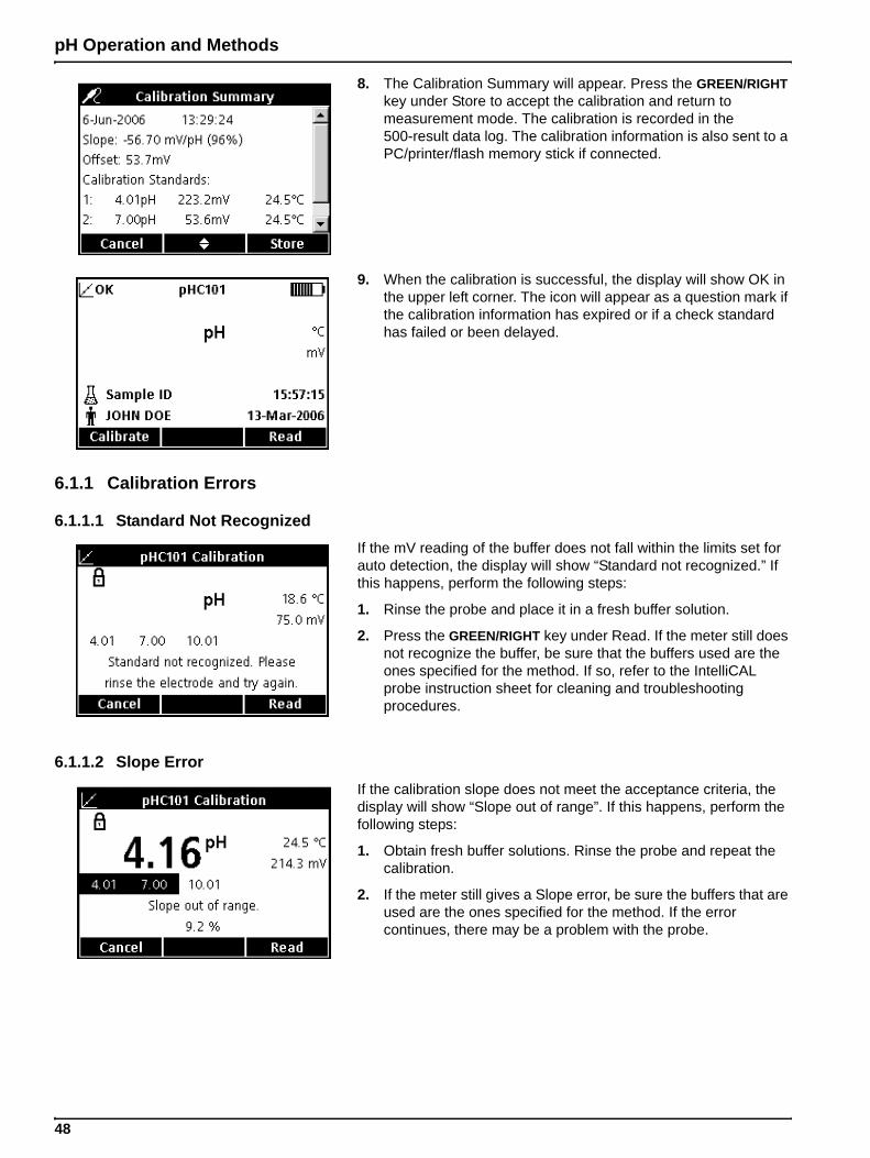
8. The Calibration Summary will appear. Press the GREEN/RIGHT key under Store to accept the calibration and return to measurement mode. The calibration is recorded in the 500-result data log. The calibration information is also sent to a PC/printer/flash memory stick if connected.
9. When the calibration is successful, the display will show OK in the upper left corner. The icon will appear as a question mark if the calibration information has expired or if a check standard has failed or been delayed.
6.1.1 Calibration Errors
6.1.1.1 Standard Not RecognizedIf the mV reading of the buffer does not fall within the limits set for auto detection, the display will show “Standard not recognized.” If this happens, perform the following steps:
1. Rinse the probe and place it in a fresh buffer solution.
2. Press the GREEN/RIGHT key under Read. If the meter still does not recognize the buffer, be sure that the buffers used are the ones specified for the method. If so, refer to the IntelliCAL probe instruction sheet for cleaning and troubleshooting procedures.
6.1.1.2 Slope ErrorIf the calibration slope does not meet the acceptance criteria, the display will show “Slope out of range”. If this happens, perform the following steps:
1. Obtain fresh buffer solutions. Rinse the probe and repeat the calibration.
2. If the meter still gives a Slope error, be sure the buffers that are used are the ones specified for the method. If the error continues, there may be a problem with the probe.
48
pH Operation and Methods
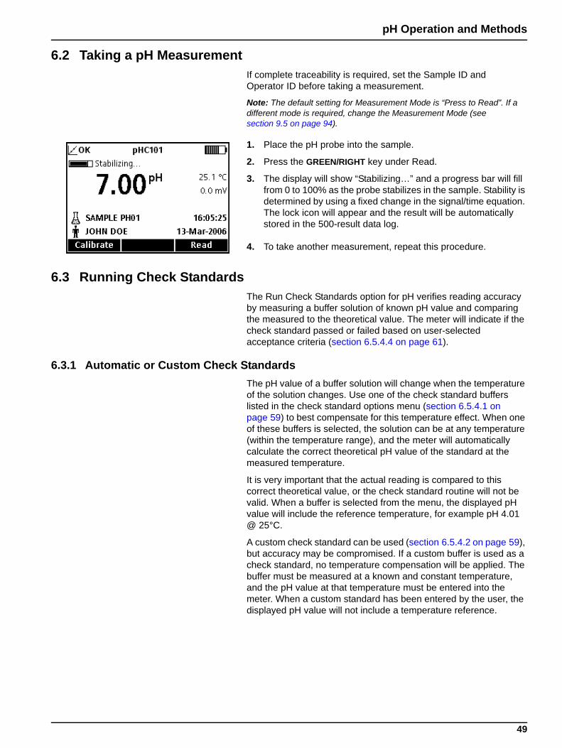
6.2 Taking a pH MeasurementIf complete traceability is required, set the Sample ID and Operator ID before taking a measurement.
Note: The default setting for Measurement Mode is “Press to Read”. If a different mode is required, change the Measurement Mode (see section 9.5 on page 94).
1. Place the pH probe into the sample.
2. Press the GREEN/RIGHT key under Read.
3. The display will show “Stabilizing…” and a progress bar will fill from 0 to 100% as the probe stabilizes in the sample. Stability is determined by using a fixed change in the signal/time equation. The lock icon will appear and the result will be automatically stored in the 500-result data log.
4. To take another measurement, repeat this procedure.
6.3 Running Check StandardsThe Run Check Standards option for pH verifies reading accuracy by measuring a buffer solution of known pH value and comparing the measured to the theoretical value. The meter will indicate if the check standard passed or failed based on user-selected acceptance criteria (section 6.5.4.4 on page 61).
6.3.1 Automatic or Custom Check StandardsThe pH value of a buffer solution will change when the temperature of the solution changes. Use one of the check standard buffers listed in the check standard options menu (section 6.5.4.1 on page 59) to best compensate for this temperature effect. When one of these buffers is selected, the solution can be at any temperature (within the temperature range), and the meter will automatically calculate the correct theoretical pH value of the standard at the measured temperature.
It is very important that the actual reading is compared to this correct theoretical value, or the check standard routine will not be valid. When a buffer is selected from the menu, the displayed pH value will include the reference temperature, for example pH 4.01 @ 25°C.
A custom check standard can be used (section 6.5.4.2 on page 59), but accuracy may be compromised. If a custom buffer is used as a check standard, no temperature compensation will be applied. The buffer must be measured at a known and constant temperature, and the pH value at that temperature must be entered into the meter. When a custom standard has been entered by the user, the displayed pH value will not include a temperature reference.
49
pH Operation and Methods
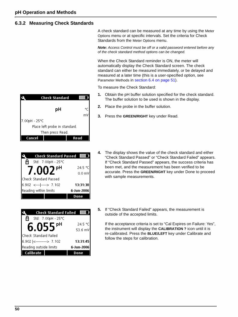
6.3.2 Measuring Check StandardsA check standard can be measured at any time by using the Meter Options menu or at specific intervals. Set the criteria for Check Standards from the Meter Options menu.
Note: Access Control must be off or a valid password entered before any of the check standard method options can be changed.
When the Check Standard reminder is ON, the meter will automatically display the Check Standard screen. The check standard can either be measured immediately, or be delayed and measured at a later time (this is a user-specified option, see Parameter Methods in section 6.4 on page 51).
To measure the Check Standard:
1. Obtain the pH buffer solution specified for the check standard. The buffer solution to be used is shown in the display.
2. Place the probe in the buffer solution.
3. Press the GREEN/RIGHT key under Read.
4. The display shows the value of the check standard and either “Check Standard Passed” or “Check Standard Failed” appears. If “Check Standard Passed” appears, the success criteria has been met, and the measurement has been verified to be accurate. Press the GREEN/RIGHT key under Done to proceed with sample measurements.
5. If “Check Standard Failed” appears, the measurement is outside of the accepted limits.
If the acceptance criteria is set to “Cal Expires on Failure: Yes”, the instrument will display the CALIBRATION ? icon until it is re-calibrated. Press the BLUE/LEFT key under Calibrate and follow the steps for calibration.
50
pH Operation and Methods
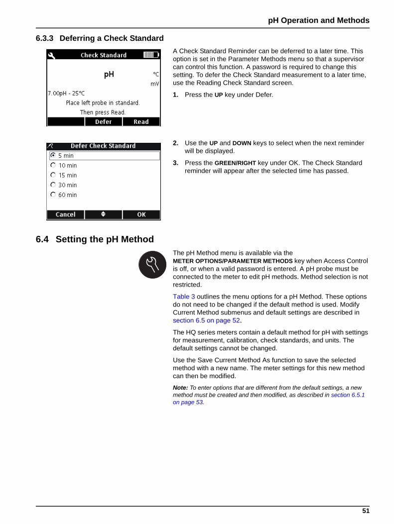
6.3.3 Deferring a Check StandardA Check Standard Reminder can be deferred to a later time. This option is set in the Parameter Methods menu so that a supervisor can control this function. A password is required to change this setting. To defer the Check Standard measurement to a later time, use the Reading Check Standard screen.
1. Press the UP key under Defer.
2. Use the UP and DOWN keys to select when the next reminder will be displayed.
3. Press the GREEN/RIGHT key under OK. The Check Standard reminder will appear after the selected time has passed.
6.4 Setting the pH MethodThe pH Method menu is available via the METER OPTIONS/PARAMETER METHODS key when Access Control is off, or when a valid password is entered. A pH probe must be connected to the meter to edit pH methods. Method selection is not restricted.
Table 3 outlines the menu options for a pH Method. These options do not need to be changed if the default method is used. Modify Current Method submenus and default settings are described in section 6.5 on page 52.
The HQ series meters contain a default method for pH with settings for measurement, calibration, check standards, and units. The default settings cannot be changed.
Use the Save Current Method As function to save the selected method with a new name. The meter settings for this new method can then be modified.
Note: To enter options that are different from the default settings, a new method must be created and then modified, as described in section 6.5.1 on page 53.
51
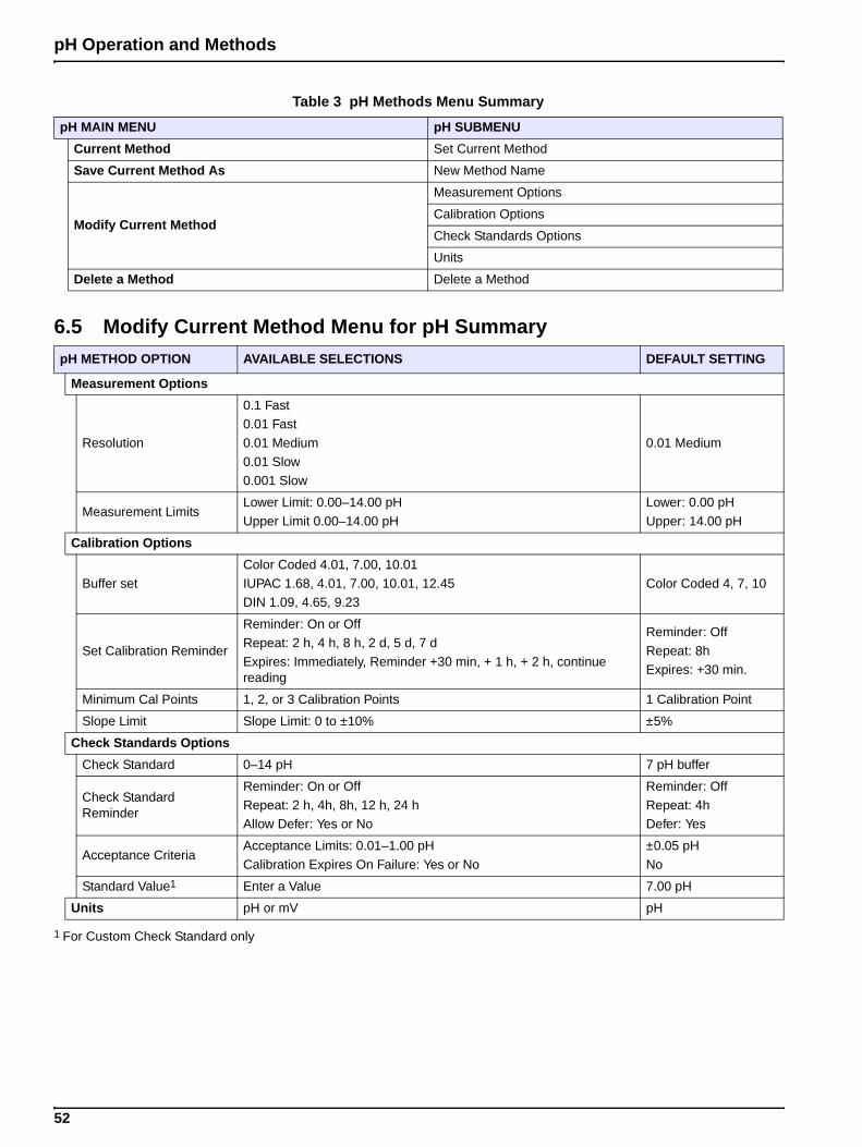
pH Operation and Methods
Table 3 pH Methods Menu Summary
pH MAIN MENU pH SUBMENU
Current Method Set Current Method
Save Current Method As New Method Name
Modify Current Method
Measurement Options
Calibration Options
Check Standards Options
Units
Delete a Method Delete a Method
6.5 Modify Current Method Menu for pH SummarypH METHOD OPTION AVAILABLE SELECTIONS DEFAULT SETTING
Measurement Options
Resolution
0.1 Fast0.01 Fast
0.01 Medium
0.01 Slow0.001 Slow
0.01 Medium
Measurement LimitsLower Limit: 0.00–14.00 pH
Upper Limit 0.00–14.00 pH
Lower: 0.00 pH
Upper: 14.00 pH
Calibration Options
Buffer setColor Coded 4.01, 7.00, 10.01
IUPAC 1.68, 4.01, 7.00, 10.01, 12.45DIN 1.09, 4.65, 9.23
Color Coded 4, 7, 10
Set Calibration Reminder
Reminder: On or Off
Repeat: 2 h, 4 h, 8 h, 2 d, 5 d, 7 d
Expires: Immediately, Reminder +30 min, + 1 h, + 2 h, continue reading
Reminder: Off
Repeat: 8hExpires: +30 min.
Minimum Cal Points 1, 2, or 3 Calibration Points 1 Calibration Point
Slope Limit Slope Limit: 0 to ±10% ±5%
Check Standards Options
Check Standard 0–14 pH 7 pH buffer
Check Standard Reminder
Reminder: On or Off
Repeat: 2 h, 4h, 8h, 12 h, 24 hAllow Defer: Yes or No
Reminder: Off
Repeat: 4hDefer: Yes
Acceptance CriteriaAcceptance Limits: 0.01–1.00 pH
Calibration Expires On Failure: Yes or No
±0.05 pH
No
Standard Value1 Enter a Value 7.00 pH
Units pH or mV pH
1 For Custom Check Standard only
52
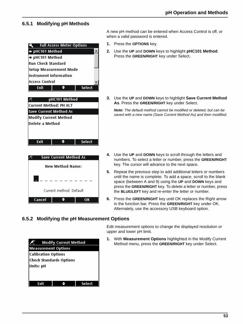
pH Operation and Methods
6.5.1 Modifying pH MethodsA new pH method can be entered when Access Control is off, or when a valid password is entered.
1. Press the OPTIONS key.
2. Use the UP and DOWN keys to highlight pHC101 Method. Press the GREEN/RIGHT key under Select.
3. Use the UP and DOWN keys to highlight Save Current Method As. Press the GREEN/RIGHT key under Select.
Note: The default method cannot be modified or deleted, but can be saved with a new name (Save Current Method As) and then modified.
4. Use the UP and DOWN keys to scroll through the letters and numbers. To select a letter or number, press the GREEN/RIGHT key. The cursor will advance to the next space.
5. Repeat the previous step to add additional letters or numbers until the name is complete. To add a space, scroll to the blank space (between A and 9) using the UP and DOWN keys and press the GREEN/RIGHT key. To delete a letter or number, press the BLUE/LEFT key and re-enter the letter or number.
6. Press the GREEN/RIGHT key until OK replaces the Right arrow in the function bar. Press the GREEN/RIGHT key under OK. Alternately, use the accessory USB keyboard option.
6.5.2 Modifying the pH Measurement OptionsEdit measurement options to change the displayed resolution or upper and lower pH limit.
1. With Measurement Options highlighted in the Modify Current Method menu, press the GREEN/RIGHT key under Select.
53
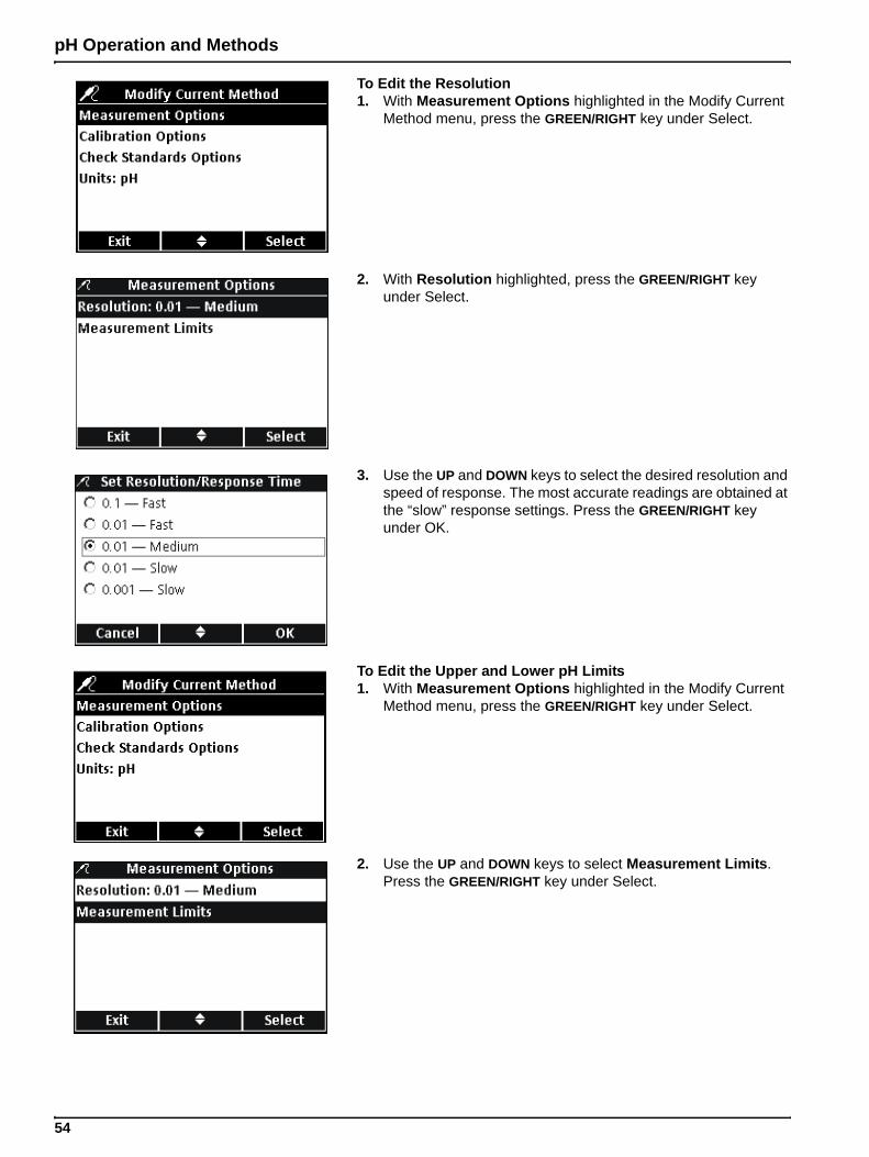
pH Operation and Methods
To Edit the Resolution1. With Measurement Options highlighted in the Modify Current
Method menu, press the GREEN/RIGHT key under Select.
2. With Resolution highlighted, press the GREEN/RIGHT key under Select.
3. Use the UP and DOWN keys to select the desired resolution and speed of response. The most accurate readings are obtained at the “slow” response settings. Press the GREEN/RIGHT key under OK.
To Edit the Upper and Lower pH Limits1. With Measurement Options highlighted in the Modify Current
Method menu, press the GREEN/RIGHT key under Select.
2. Use the UP and DOWN keys to select Measurement Limits. Press the GREEN/RIGHT key under Select.
54
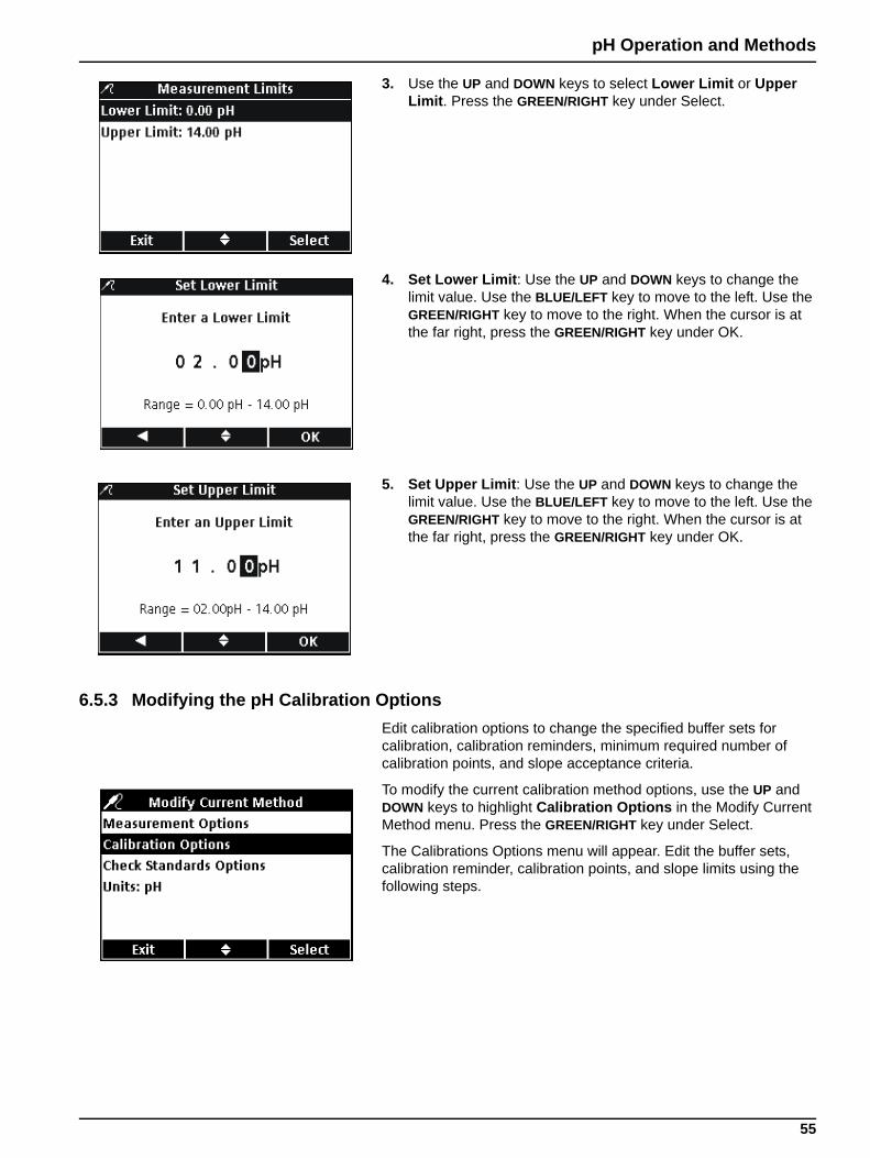
pH Operation and Methods
3. Use the UP and DOWN keys to select Lower Limit or Upper Limit. Press the GREEN/RIGHT key under Select.
4. Set Lower Limit: Use the UP and DOWN keys to change the limit value. Use the BLUE/LEFT key to move to the left. Use the GREEN/RIGHT key to move to the right. When the cursor is at the far right, press the GREEN/RIGHT key under OK.
5. Set Upper Limit: Use the UP and DOWN keys to change the limit value. Use the BLUE/LEFT key to move to the left. Use the GREEN/RIGHT key to move to the right. When the cursor is at the far right, press the GREEN/RIGHT key under OK.
6.5.3 Modifying the pH Calibration OptionsEdit calibration options to change the specified buffer sets for calibration, calibration reminders, minimum required number of calibration points, and slope acceptance criteria.
To modify the current calibration method options, use the UP and DOWN keys to highlight Calibration Options in the Modify Current Method menu. Press the GREEN/RIGHT key under Select.
The Calibrations Options menu will appear. Edit the buffer sets, calibration reminder, calibration points, and slope limits using the following steps.
55
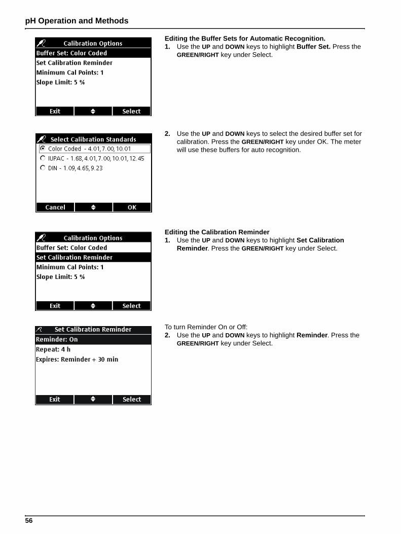
pH Operation and Methods
Editing the Buffer Sets for Automatic Recognition.1. Use the UP and DOWN keys to highlight Buffer Set. Press the
GREEN/RIGHT key under Select.
2. Use the UP and DOWN keys to select the desired buffer set for calibration. Press the GREEN/RIGHT key under OK. The meter will use these buffers for auto recognition.
Editing the Calibration Reminder1. Use the UP and DOWN keys to highlight Set Calibration
Reminder. Press the GREEN/RIGHT key under Select.
To turn Reminder On or Off:2. Use the UP and DOWN keys to highlight Reminder. Press the
GREEN/RIGHT key under Select.
56
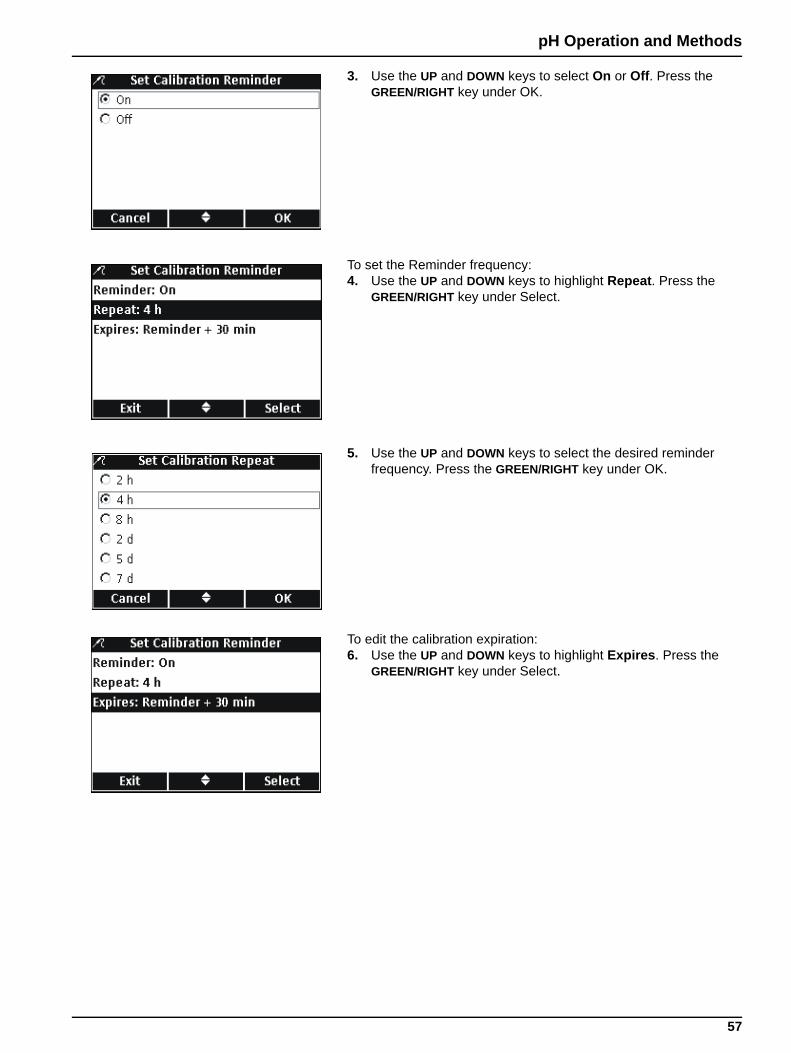
pH Operation and Methods
3. Use the UP and DOWN keys to select On or Off. Press the GREEN/RIGHT key under OK.
To set the Reminder frequency:4. Use the UP and DOWN keys to highlight Repeat. Press the
GREEN/RIGHT key under Select.
5. Use the UP and DOWN keys to select the desired reminder frequency. Press the GREEN/RIGHT key under OK.
To edit the calibration expiration:6. Use the UP and DOWN keys to highlight Expires. Press the
GREEN/RIGHT key under Select.
57
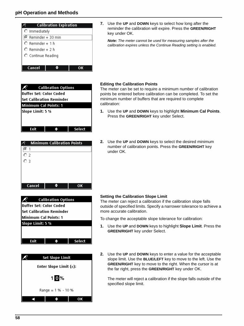
pH Operation and Methods
7. Use the UP and DOWN keys to select how long after the reminder the calibration will expire. Press the GREEN/RIGHT key under OK.
Note: The meter cannot be used for measuring samples after the calibration expires unless the Continue Reading setting is enabled.
Editing the Calibration PointsThe meter can be set to require a minimum number of calibration points be entered before calibration can be completed. To set the minimum number of buffers that are required to complete calibration:
1. Use the UP and DOWN keys to highlight Minimum Cal Points. Press the GREEN/RIGHT key under Select.
2. Use the UP and DOWN keys to select the desired minimum number of calibration points. Press the GREEN/RIGHT key under OK.
Setting the Calibration Slope LimitThe meter can reject a calibration if the calibration slope falls outside of specified limits. Specify a narrower tolerance to achieve a more accurate calibration.
To change the acceptable slope tolerance for calibration:
1. Use the UP and DOWN keys to highlight Slope Limit. Press the GREEN/RIGHT key under Select.
2. Use the UP and DOWN keys to enter a value for the acceptable slope limit. Use the BLUE/LEFT key to move to the left. Use the GREEN/RIGHT key to move to the right. When the cursor is at the far right, press the GREEN/RIGHT key under OK.
The meter will reject a calibration if the slope falls outside of the specified slope limit.
58
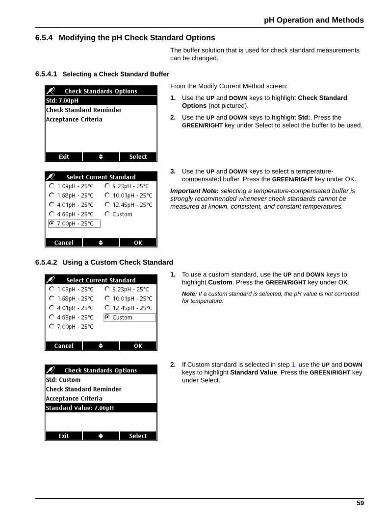
pH Operation and Methods
6.5.4 Modifying the pH Check Standard OptionsThe buffer solution that is used for check standard measurements can be changed.
6.5.4.1 Selecting a Check Standard Buffer
From the Modify Current Method screen:
1. Use the UP and DOWN keys to highlight Check Standard Options (not pictured).
2. Use the UP and DOWN keys to highlight Std:. Press the GREEN/RIGHT key under Select to select the buffer to be used.
3. Use the UP and DOWN keys to select a temperature- compensated buffer. Press the GREEN/RIGHT key under OK.
Important Note: selecting a temperature-compensated buffer is strongly recommended whenever check standards cannot be measured at known, consistent, and constant temperatures.
6.5.4.2 Using a Custom Check Standard1. To use a custom standard, use the UP and DOWN keys to
highlight Custom. Press the GREEN/RIGHT key under OK.
Note: If a custom standard is selected, the pH value is not corrected for temperature.
2. If Custom standard is selected in step 1, use the UP and DOWN keys to highlight Standard Value. Press the GREEN/RIGHT key under Select.
59
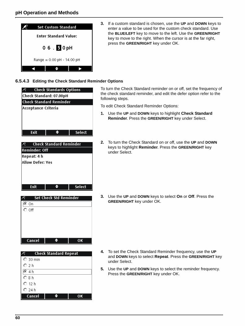
pH Operation and Methods
3. If a custom standard is chosen, use the UP and DOWN keys to enter a value to be used for the custom check standard. Use the BLUE/LEFT key to move to the left. Use the GREEN/RIGHT key to move to the right. When the cursor is at the far right, press the GREEN/RIGHT key under OK.
6.5.4.3 Editing the Check Standard Reminder Options
To turn the Check Standard reminder on or off, set the frequency of the check standard reminder, and edit the defer option refer to the following steps.
To edit Check Standard Reminder Options:
1. Use the UP and DOWN keys to highlight Check Standard Reminder. Press the GREEN/RIGHT key under Select.
2. To turn the Check Standard on or off, use the UP and DOWN keys to highlight Reminder. Press the GREEN/RIGHT key under Select.
3. Use the UP and DOWN keys to select On or Off. Press the GREEN/RIGHT key under OK.
4. To set the Check Standard Reminder frequency, use the UP and DOWN keys to select Repeat. Press the GREEN/RIGHT key under Select.
5. Use the UP and DOWN keys to select the reminder frequency. Press the GREEN/RIGHT key under OK.
60
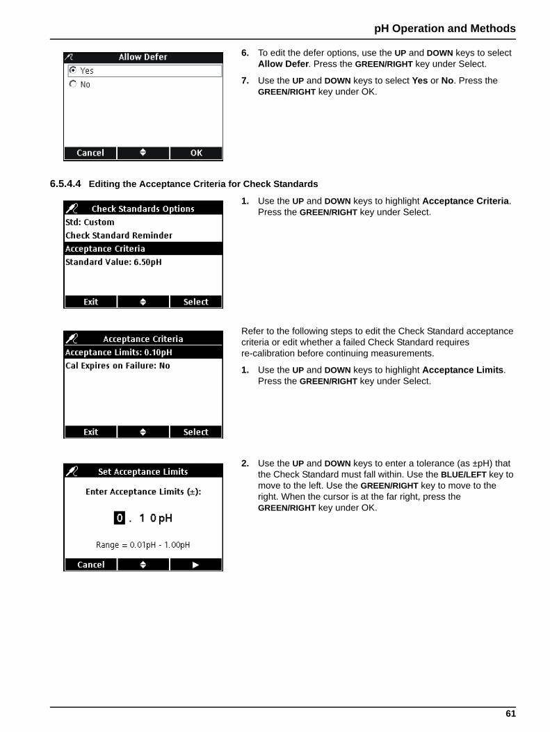
pH Operation and Methods
6. To edit the defer options, use the UP and DOWN keys to select Allow Defer. Press the GREEN/RIGHT key under Select.
7. Use the UP and DOWN keys to select Yes or No. Press the GREEN/RIGHT key under OK.
6.5.4.4 Editing the Acceptance Criteria for Check Standards
1. Use the UP and DOWN keys to highlight Acceptance Criteria. Press the GREEN/RIGHT key under Select.
Refer to the following steps to edit the Check Standard acceptance criteria or edit whether a failed Check Standard requires re-calibration before continuing measurements.
1. Use the UP and DOWN keys to highlight Acceptance Limits. Press the GREEN/RIGHT key under Select.
2. Use the UP and DOWN keys to enter a tolerance (as ±pH) that the Check Standard must fall within. Use the BLUE/LEFT key to move to the left. Use the GREEN/RIGHT key to move to the right. When the cursor is at the far right, press the GREEN/RIGHT key under OK.
61
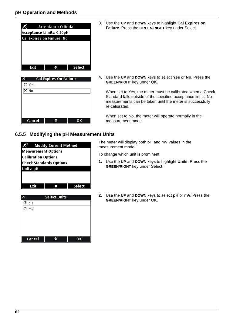
pH Operation and Methods
3. Use the UP and DOWN keys to highlight Cal Expires on Failure. Press the GREEN/RIGHT key under Select.
4. Use the UP and DOWN keys to select Yes or No. Press the GREEN/RIGHT key under OK.
When set to Yes, the meter must be calibrated when a Check Standard falls outside of the specified acceptance limits. No measurements can be taken until the meter is successfully re-calibrated.
When set to No, the meter will operate normally in the measurement mode.
6.5.5 Modifying the pH Measurement UnitsThe meter will display both pH and mV values in the measurement mode.
To change which unit is prominent:
1. Use the UP and DOWN keys to highlight Units. Press the GREEN/RIGHT key under Select.
2. Use the UP and DOWN keys to select pH or mV. Press the GREEN/RIGHT key under OK.
62
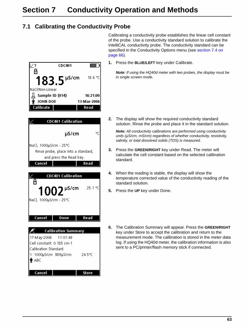
Section 7 Conductivity Operation and Methods
7.1 Calibrating the Conductivity ProbeCalibrating a conductivity probe establishes the linear cell constant of the probe. Use a conductivity standard solution to calibrate the IntelliCAL conductivity probe. The conductivity standard can be specified in the Conductivity Options menu (see section 7.4 on page 66).
1. Press the BLUE/LEFT key under Calibrate.
Note: If using the HQ40d meter with two probes, the display must be in single screen mode.
2. The display will show the required conductivity standard solution. Rinse the probe and place it in the standard solution.
Note: All conductivity calibrations are performed using conductivity units (µS/cm, mS/cm) regardless of whether conductivity, resistivity, salinity, or total dissolved solids (TDS) is measured.
3. Press the GREEN/RIGHT key under Read. The meter will calculate the cell constant based on the selected calibration standard.
4. When the reading is stable, the display will show the temperature corrected value of the conductivity reading of the standard solution.
5. Press the UP key under Done.
6. The Calibration Summary will appear. Press the GREEN/RIGHT key under Store to accept the calibration and return to the measurement mode. The calibration is stored in the meter data log. If using the HQ40d meter, the calibration information is also sent to a PC/printer/flash memory stick if connected.
63
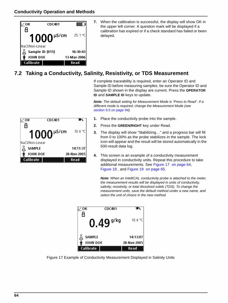
Conductivity Operation and Methods
7. When the calibration is successful, the display will show OK in the upper left corner. A question mark will be displayed if a calibration has expired or if a check standard has failed or been delayed.
7.2 Taking a Conductivity, Salinity, Resistivity, or TDS MeasurementIf complete traceability is required, enter an Operator ID and Sample ID before measuring samples: be sure the Operator ID and Sample ID shown in the display are current. Press the OPERATOR ID and SAMPLE ID keys to update.
Note: The default setting for Measurement Mode is “Press to Read”. If a different mode is required, change the Measurement Mode (see section 9.5 on page 94).
1. Place the conductivity probe into the sample.
2. Press the GREEN/RIGHT key under Read.
3. The display will show “Stabilizing…” and a progress bar will fill from 0 to 100% as the probe stabilizes in the sample. The lock icon will appear and the result will be stored automatically in the 500-result data log.
4. This screen is an example of a conductivity measurement displayed in conductivity units. Repeat this procedure to take additional measurements. See Figure 17 on page 64, Figure 18 , and Figure 19 on page 65.
Note: When an IntelliCAL conductivity probe is attached to the meter, the measurement results will be displayed in units of conductivity, salinity, resistivity, or total dissolved solids (TDS). To change the measurement units, save the default method under a new name, and select the unit of choice in the new method.
Figure 17 Example of Conductivity Measurement Displayed in Salinity Units
64

Conductivity Operation and Methods
7.3 Running Check Standards Manually or AutomaticallyWhen the Check Standard reminder is on, the meter will automatically display the Check Standard screen. The check standard can either be measured immediately, or the measurement can be delayed until a later time.
To measure the Check Standard:
1. Obtain the conductivity standard solution specified for the check standard. The conductivity solution to be used is shown on the display.
2. Place the probe in the conductivity standard.
3. Press the GREEN/RIGHT key under Read.
4. The display will show the value of the check standard and either “Check Standard Passed” or “Check Standard Failed”.
5. If “Check Standard Passed” is displayed, the reading is verified to be accurate. Press the GREEN/RIGHT key under Done to proceed with sample measurements.
Figure 18 Example of Conductivity Measurement Displayed in TDS Units
Figure 19 Example of Conductivity Measurement Displayed in Resistivity Units
65
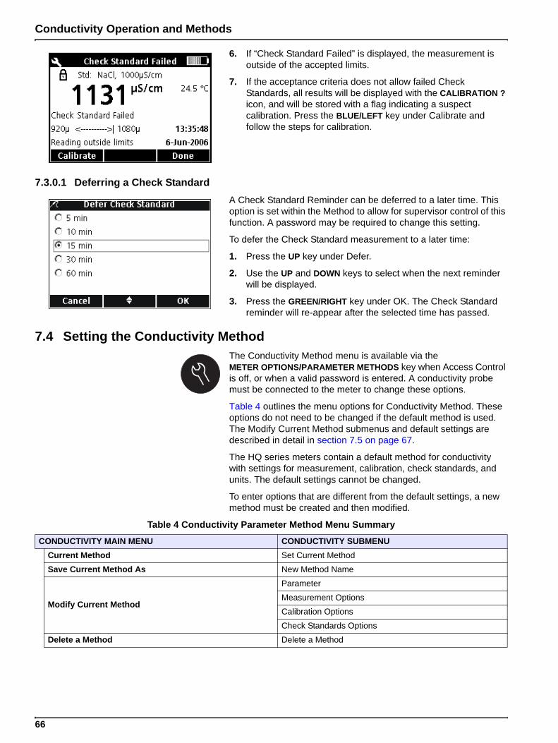
Conductivity Operation and Methods
6. If “Check Standard Failed” is displayed, the measurement is outside of the accepted limits.
7. If the acceptance criteria does not allow failed Check Standards, all results will be displayed with the CALIBRATION ? icon, and will be stored with a flag indicating a suspect calibration. Press the BLUE/LEFT key under Calibrate and follow the steps for calibration.
7.3.0.1 Deferring a Check StandardA Check Standard Reminder can be deferred to a later time. This option is set within the Method to allow for supervisor control of this function. A password may be required to change this setting.
To defer the Check Standard measurement to a later time:
1. Press the UP key under Defer.
2. Use the UP and DOWN keys to select when the next reminder will be displayed.
3. Press the GREEN/RIGHT key under OK. The Check Standard reminder will re-appear after the selected time has passed.
7.4 Setting the Conductivity MethodThe Conductivity Method menu is available via the METER OPTIONS/PARAMETER METHODS key when Access Control is off, or when a valid password is entered. A conductivity probe must be connected to the meter to change these options.
Table 4 outlines the menu options for Conductivity Method. These options do not need to be changed if the default method is used. The Modify Current Method submenus and default settings are described in detail in section 7.5 on page 67.
The HQ series meters contain a default method for conductivity with settings for measurement, calibration, check standards, and units. The default settings cannot be changed.
To enter options that are different from the default settings, a new method must be created and then modified.
Table 4 Conductivity Parameter Method Menu Summary
CONDUCTIVITY MAIN MENU CONDUCTIVITY SUBMENU
Current Method Set Current Method
Save Current Method As New Method Name
Modify Current Method
Parameter
Measurement Options
Calibration Options
Check Standards Options
Delete a Method Delete a Method
66
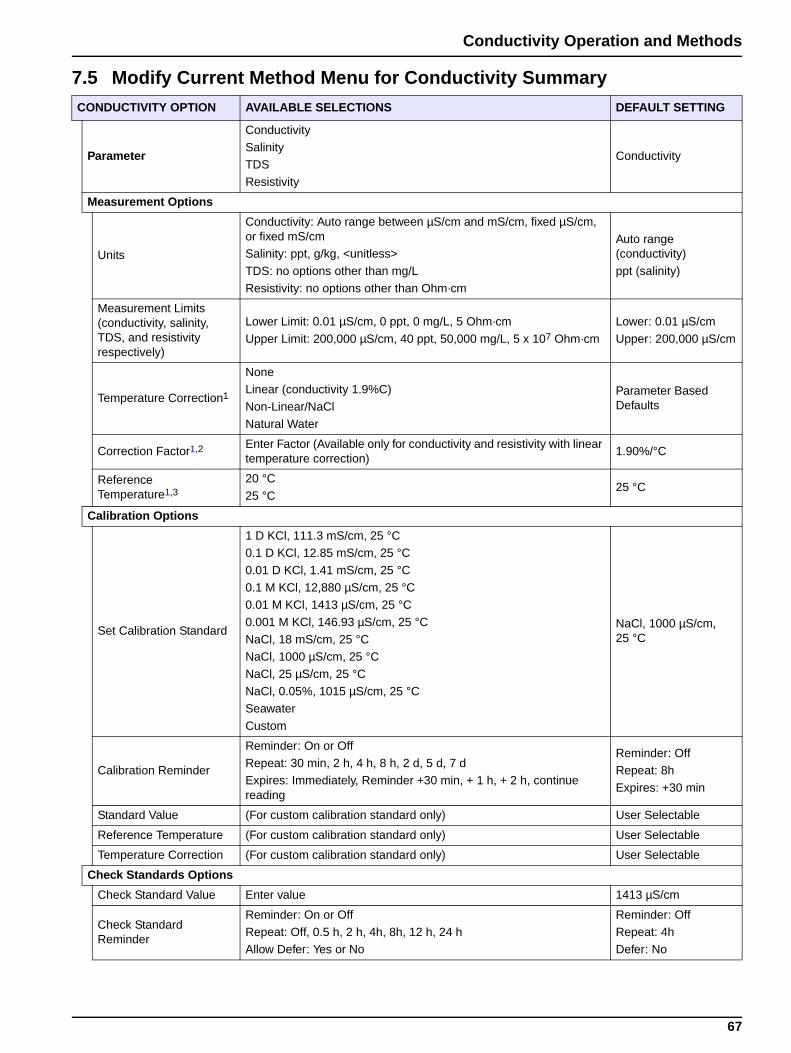
Conductivity Operation and Methods
7.5 Modify Current Method Menu for Conductivity SummaryCONDUCTIVITY OPTION AVAILABLE SELECTIONS DEFAULT SETTING
Parameter
Conductivity
SalinityTDS
Resistivity
Conductivity
Measurement Options
Units
Conductivity: Auto range between µS/cm and mS/cm, fixed µS/cm, or fixed mS/cmSalinity: ppt, g/kg, <unitless>
TDS: no options other than mg/L
Resistivity: no options other than Ohm·cm
Auto range (conductivity)
ppt (salinity)
Measurement Limits (conductivity, salinity, TDS, and resistivity respectively)
Lower Limit: 0.01 µS/cm, 0 ppt, 0 mg/L, 5 Ohm·cm
Upper Limit: 200,000 µS/cm, 40 ppt, 50,000 mg/L, 5 x 10⁷ Ohm·cm
Lower: 0.01 µS/cm
Upper: 200,000 µS/cm
Temperature Correction1
NoneLinear (conductivity 1.9%C)
Non-Linear/NaCl
Natural Water
Parameter Based Defaults
Correction Factor1,2 Enter Factor (Available only for conductivity and resistivity with linear temperature correction)
1.90%/°C
Reference Temperature1,3
20 °C
25 °C25 °C
Calibration Options
Set Calibration Standard
1 D KCl, 111.3 mS/cm, 25 °C0.1 D KCl, 12.85 mS/cm, 25 °C
0.01 D KCl, 1.41 mS/cm, 25 °C
0.1 M KCl, 12,880 µS/cm, 25 °C0.01 M KCl, 1413 µS/cm, 25 °C
0.001 M KCl, 146.93 µS/cm, 25 °C
NaCl, 18 mS/cm, 25 °CNaCl, 1000 µS/cm, 25 °C
NaCl, 25 µS/cm, 25 °C
NaCl, 0.05%, 1015 µS/cm, 25 °CSeawater
Custom
NaCl, 1000 µS/cm, 25 °C
Calibration Reminder
Reminder: On or Off
Repeat: 30 min, 2 h, 4 h, 8 h, 2 d, 5 d, 7 dExpires: Immediately, Reminder +30 min, + 1 h, + 2 h, continue reading
Reminder: OffRepeat: 8h
Expires: +30 min
Standard Value (For custom calibration standard only) User Selectable
Reference Temperature (For custom calibration standard only) User Selectable
Temperature Correction (For custom calibration standard only) User Selectable
Check Standards Options
Check Standard Value Enter value 1413 µS/cm
Check Standard Reminder
Reminder: On or Off
Repeat: Off, 0.5 h, 2 h, 4h, 8h, 12 h, 24 hAllow Defer: Yes or No
Reminder: Off
Repeat: 4hDefer: No
67
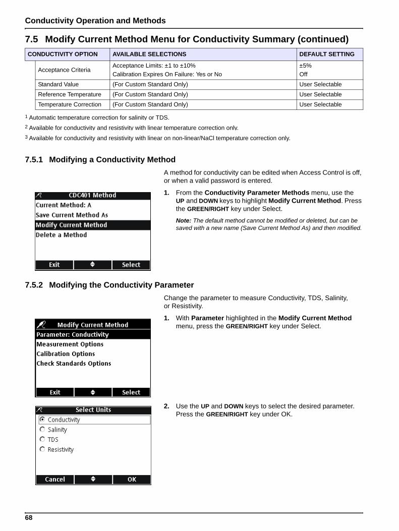
Conductivity Operation and Methods
7.5.1 Modifying a Conductivity MethodA method for conductivity can be edited when Access Control is off, or when a valid password is entered.
1. From the Conductivity Parameter Methods menu, use the UP and DOWN keys to highlight Modify Current Method. Press the GREEN/RIGHT key under Select.
Note: The default method cannot be modified or deleted, but can be saved with a new name (Save Current Method As) and then modified.
7.5.2 Modifying the Conductivity ParameterChange the parameter to measure Conductivity, TDS, Salinity, or Resistivity.
1. With Parameter highlighted in the Modify Current Method menu, press the GREEN/RIGHT key under Select.
2. Use the UP and DOWN keys to select the desired parameter. Press the GREEN/RIGHT key under OK.
Acceptance CriteriaAcceptance Limits: ±1 to ±10%
Calibration Expires On Failure: Yes or No
±5%
Off
Standard Value (For Custom Standard Only) User Selectable
Reference Temperature (For Custom Standard Only) User Selectable
Temperature Correction (For Custom Standard Only) User Selectable
1 Automatic temperature correction for salinity or TDS.2 Available for conductivity and resistivity with linear temperature correction only.3 Available for conductivity and resistivity with linear on non-linear/NaCl temperature correction only.
7.5 Modify Current Method Menu for Conductivity Summary (continued)CONDUCTIVITY OPTION AVAILABLE SELECTIONS DEFAULT SETTING
68
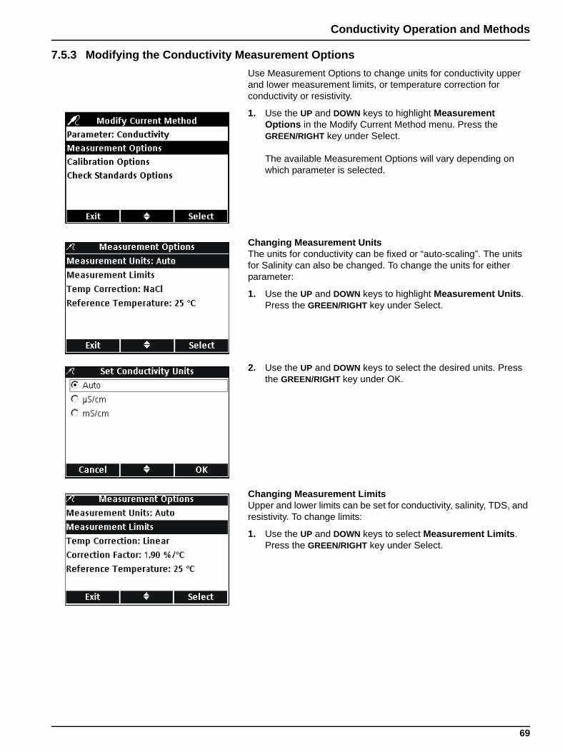
Conductivity Operation and Methods
7.5.3 Modifying the Conductivity Measurement OptionsUse Measurement Options to change units for conductivity upper and lower measurement limits, or temperature correction for conductivity or resistivity.
1. Use the UP and DOWN keys to highlight Measurement Options in the Modify Current Method menu. Press the GREEN/RIGHT key under Select.
The available Measurement Options will vary depending on which parameter is selected.
Changing Measurement UnitsThe units for conductivity can be fixed or “auto-scaling”. The units for Salinity can also be changed. To change the units for either parameter:
1. Use the UP and DOWN keys to highlight Measurement Units. Press the GREEN/RIGHT key under Select.
2. Use the UP and DOWN keys to select the desired units. Press the GREEN/RIGHT key under OK.
Changing Measurement LimitsUpper and lower limits can be set for conductivity, salinity, TDS, and resistivity. To change limits:
1. Use the UP and DOWN keys to select Measurement Limits. Press the GREEN/RIGHT key under Select.
69
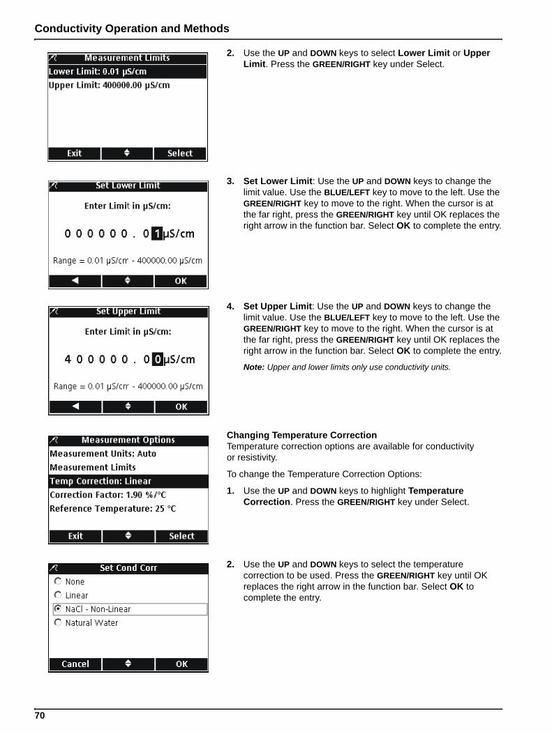
Conductivity Operation and Methods
2. Use the UP and DOWN keys to select Lower Limit or Upper Limit. Press the GREEN/RIGHT key under Select.
3. Set Lower Limit: Use the UP and DOWN keys to change the limit value. Use the BLUE/LEFT key to move to the left. Use the GREEN/RIGHT key to move to the right. When the cursor is at the far right, press the GREEN/RIGHT key until OK replaces the right arrow in the function bar. Select OK to complete the entry.
4. Set Upper Limit: Use the UP and DOWN keys to change the limit value. Use the BLUE/LEFT key to move to the left. Use the GREEN/RIGHT key to move to the right. When the cursor is at the far right, press the GREEN/RIGHT key until OK replaces the right arrow in the function bar. Select OK to complete the entry.
Note: Upper and lower limits only use conductivity units.
Changing Temperature CorrectionTemperature correction options are available for conductivity or resistivity.
To change the Temperature Correction Options:
1. Use the UP and DOWN keys to highlight Temperature Correction. Press the GREEN/RIGHT key under Select.
2. Use the UP and DOWN keys to select the temperature correction to be used. Press the GREEN/RIGHT key until OK replaces the right arrow in the function bar. Select OK to complete the entry.
70
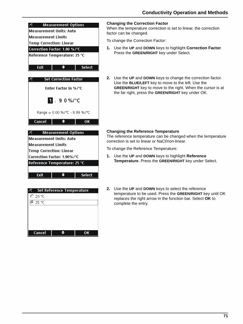
Conductivity Operation and Methods
Changing the Correction FactorWhen the temperature correction is set to linear, the correction factor can be changed.
To change the Correction Factor:
1. Use the UP and DOWN keys to highlight Correction Factor. Press the GREEN/RIGHT key under Select.
2. Use the UP and DOWN keys to change the correction factor. Use the BLUE/LEFT key to move to the left. Use the GREEN/RIGHT key to move to the right. When the cursor is at the far right, press the GREEN/RIGHT key under OK.
Changing the Reference TemperatureThe reference temperature can be changed when the temperature correction is set to linear or NaCl/non-linear.
To change the Reference Temperature:
1. Use the UP and DOWN keys to highlight Reference Temperature. Press the GREEN/RIGHT key under Select.
2. Use the UP and DOWN keys to select the reference temperature to be used. Press the GREEN/RIGHT key until OK replaces the right arrow in the function bar. Select OK to complete the entry.
71
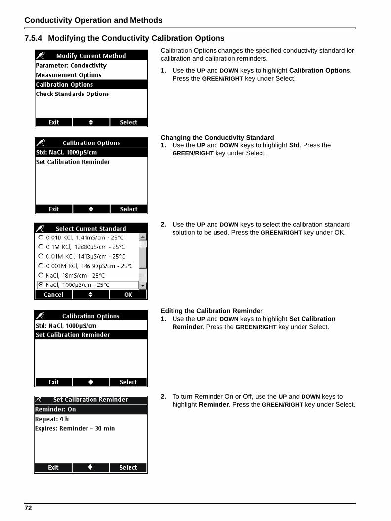
Conductivity Operation and Methods
7.5.4 Modifying the Conductivity Calibration OptionsCalibration Options changes the specified conductivity standard for calibration and calibration reminders.
1. Use the UP and DOWN keys to highlight Calibration Options. Press the GREEN/RIGHT key under Select.
Changing the Conductivity Standard1. Use the UP and DOWN keys to highlight Std. Press the
GREEN/RIGHT key under Select.
2. Use the UP and DOWN keys to select the calibration standard solution to be used. Press the GREEN/RIGHT key under OK.
Editing the Calibration Reminder1. Use the UP and DOWN keys to highlight Set Calibration
Reminder. Press the GREEN/RIGHT key under Select.
2. To turn Reminder On or Off, use the UP and DOWN keys to highlight Reminder. Press the GREEN/RIGHT key under Select.
72
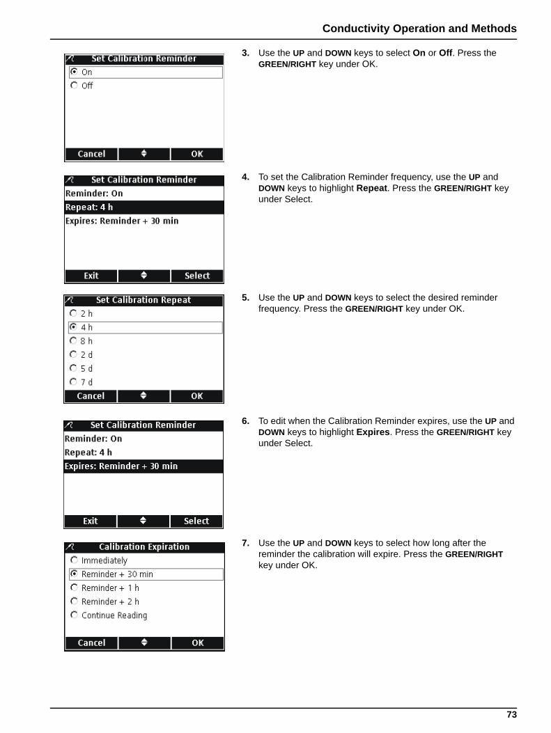
Conductivity Operation and Methods
3. Use the UP and DOWN keys to select On or Off. Press the GREEN/RIGHT key under OK.
4. To set the Calibration Reminder frequency, use the UP and DOWN keys to highlight Repeat. Press the GREEN/RIGHT key under Select.
5. Use the UP and DOWN keys to select the desired reminder frequency. Press the GREEN/RIGHT key under OK.
6. To edit when the Calibration Reminder expires, use the UP and DOWN keys to highlight Expires. Press the GREEN/RIGHT key under Select.
7. Use the UP and DOWN keys to select how long after the reminder the calibration will expire. Press the GREEN/RIGHT key under OK.
73
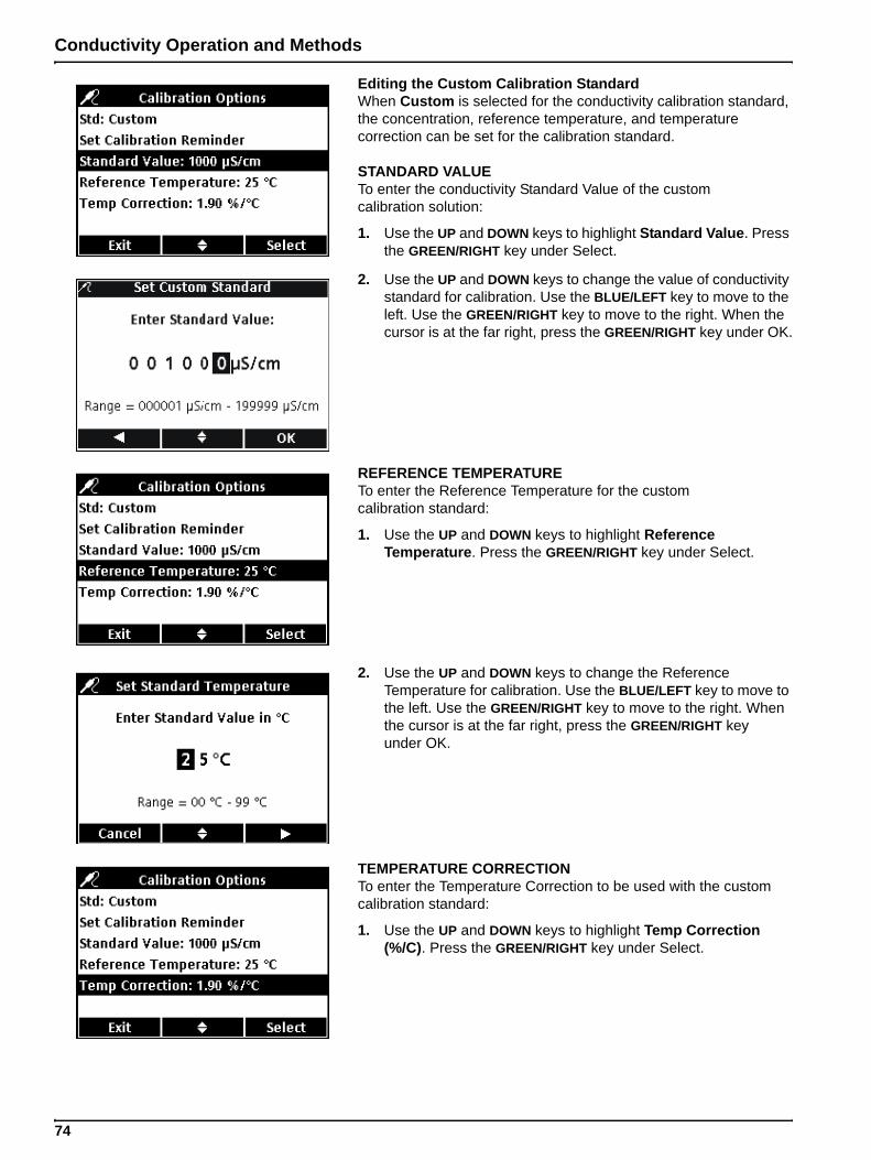
Conductivity Operation and Methods
Editing the Custom Calibration StandardWhen Custom is selected for the conductivity calibration standard, the concentration, reference temperature, and temperature correction can be set for the calibration standard.
STANDARD VALUETo enter the conductivity Standard Value of the custom calibration solution:
1. Use the UP and DOWN keys to highlight Standard Value. Press the GREEN/RIGHT key under Select.
2. Use the UP and DOWN keys to change the value of conductivity standard for calibration. Use the BLUE/LEFT key to move to the left. Use the GREEN/RIGHT key to move to the right. When the cursor is at the far right, press the GREEN/RIGHT key under OK.
REFERENCE TEMPERATURETo enter the Reference Temperature for the custom calibration standard:
1. Use the UP and DOWN keys to highlight Reference Temperature. Press the GREEN/RIGHT key under Select.
2. Use the UP and DOWN keys to change the Reference Temperature for calibration. Use the BLUE/LEFT key to move to the left. Use the GREEN/RIGHT key to move to the right. When the cursor is at the far right, press the GREEN/RIGHT key under OK.
TEMPERATURE CORRECTIONTo enter the Temperature Correction to be used with the custom calibration standard:
1. Use the UP and DOWN keys to highlight Temp Correction (%/C). Press the GREEN/RIGHT key under Select.
74
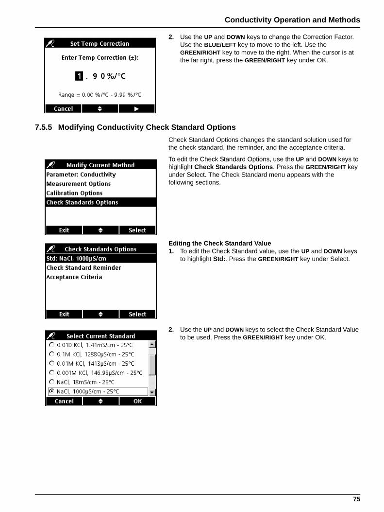
Conductivity Operation and Methods
2. Use the UP and DOWN keys to change the Correction Factor. Use the BLUE/LEFT key to move to the left. Use the GREEN/RIGHT key to move to the right. When the cursor is at the far right, press the GREEN/RIGHT key under OK.
7.5.5 Modifying Conductivity Check Standard OptionsCheck Standard Options changes the standard solution used for the check standard, the reminder, and the acceptance criteria.
To edit the Check Standard Options, use the UP and DOWN keys to highlight Check Standards Options. Press the GREEN/RIGHT key under Select. The Check Standard menu appears with the following sections.
Editing the Check Standard Value1. To edit the Check Standard value, use the UP and DOWN keys
to highlight Std:. Press the GREEN/RIGHT key under Select.
2. Use the UP and DOWN keys to select the Check Standard Value to be used. Press the GREEN/RIGHT key under OK.
75
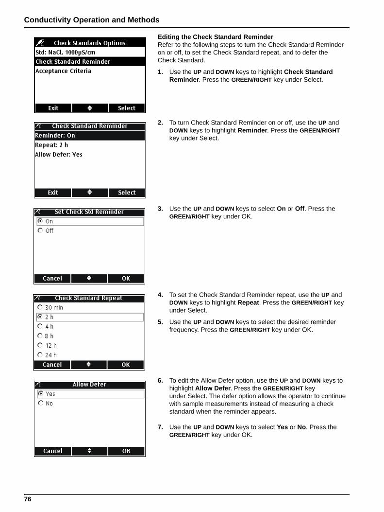
Conductivity Operation and Methods
Editing the Check Standard ReminderRefer to the following steps to turn the Check Standard Reminder on or off, to set the Check Standard repeat, and to defer the Check Standard.
1. Use the UP and DOWN keys to highlight Check Standard Reminder. Press the GREEN/RIGHT key under Select.
2. To turn Check Standard Reminder on or off, use the UP and DOWN keys to highlight Reminder. Press the GREEN/RIGHT key under Select.
3. Use the UP and DOWN keys to select On or Off. Press the GREEN/RIGHT key under OK.
4. To set the Check Standard Reminder repeat, use the UP and DOWN keys to highlight Repeat. Press the GREEN/RIGHT key under Select.
5. Use the UP and DOWN keys to select the desired reminder frequency. Press the GREEN/RIGHT key under OK.
6. To edit the Allow Defer option, use the UP and DOWN keys to highlight Allow Defer. Press the GREEN/RIGHT key under Select. The defer option allows the operator to continue with sample measurements instead of measuring a check standard when the reminder appears.
7. Use the UP and DOWN keys to select Yes or No. Press the GREEN/RIGHT key under OK.
76
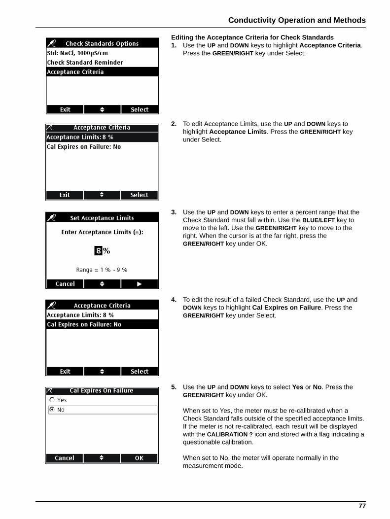
Conductivity Operation and Methods
Editing the Acceptance Criteria for Check Standards1. Use the UP and DOWN keys to highlight Acceptance Criteria.
Press the GREEN/RIGHT key under Select.
2. To edit Acceptance Limits, use the UP and DOWN keys to highlight Acceptance Limits. Press the GREEN/RIGHT key under Select.
3. Use the UP and DOWN keys to enter a percent range that the Check Standard must fall within. Use the BLUE/LEFT key to move to the left. Use the GREEN/RIGHT key to move to the right. When the cursor is at the far right, press the GREEN/RIGHT key under OK.
4. To edit the result of a failed Check Standard, use the UP and DOWN keys to highlight Cal Expires on Failure. Press the GREEN/RIGHT key under Select.
5. Use the UP and DOWN keys to select Yes or No. Press the GREEN/RIGHT key under OK.
When set to Yes, the meter must be re-calibrated when a Check Standard falls outside of the specified acceptance limits. If the meter is not re-calibrated, each result will be displayed with the CALIBRATION ? icon and stored with a flag indicating a questionable calibration.
When set to No, the meter will operate normally in the measurement mode.
77
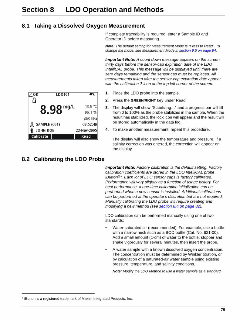
Section 8 LDO Operation and Methods
8.1 Taking a Dissolved Oxygen MeasurementIf complete traceability is required, enter a Sample ID and Operator ID before measuring.
Note: The default setting for Measurement Mode is “Press to Read”. To change the mode, see Measurement Mode in section 9.5 on page 94.
Important Note: A count down message appears on the screen thirty days before the sensor-cap expiration date of the LDO IntelliCAL probe. This message will be displayed until there are zero days remaining and the sensor cap must be replaced. All measurements taken after the sensor cap expiration date appear with the calibration ? icon at the top left corner of the screen.
1. Place the LDO probe into the sample.
2. Press the GREEN/RIGHT key under Read.
3. The display will show “Stabilizing…” and a progress bar will fill from 0 to 100% as the probe stabilizes in the sample. When the result has stabilized, the lock icon will appear and the result will be stored automatically in the data log.
4. To make another measurement, repeat this procedure.
The display will also show the temperature and pressure. If a salinity correction was entered, the correction will appear on the display.
8.2 Calibrating the LDO ProbeImportant Note: Factory calibration is the default setting. Factory calibration coefficients are stored in the LDO IntelliCAL probe iButton®*. Each lot of LDO sensor caps is factory calibrated. Performance will vary slightly as a function of usage history. For best performance, a one-time calibration initialization can be performed when a new sensor is installed. Additional calibrations can be performed at the operator's discretion but are not required. Manually calibrating the LDO probe will require creating and modifying a new method (see section 8.4 on page 82).
LDO calibration can be performed manually using one of two standards:
• Water-saturated air (recommended). For example, use a bottle with a narrow neck such as a BOD bottle (Cat. No. 621-00). Add a small amount (1-cm) of water to the bottle, stopper and shake vigorously for several minutes, then insert the probe.
• A water sample with a known dissolved oxygen concentration. The concentration must be determined by Winkler titration, or by calculation of a saturated-air water sample using existing pressure, temperature, and salinity conditions.
Note: Modify the LDO Method to use a water sample as a standard.
* iButton is a registered trademark of Maxim Integrated Products, Inc.
79
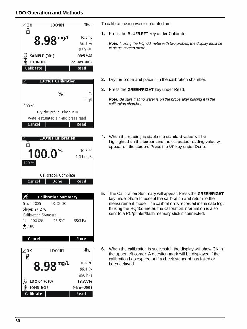
LDO Operation and Methods
To calibrate using water-saturated air:
1. Press the BLUE/LEFT key under Calibrate.
Note: If using the HQ40d meter with two probes, the display must be in single screen mode.
2. Dry the probe and place it in the calibration chamber.
3. Press the GREEN/RIGHT key under Read.
Note: Be sure that no water is on the probe after placing it in the calibration chamber.
4. When the reading is stable the standard value will be highlighted on the screen and the calibrated reading value will appear on the screen. Press the UP key under Done.
5. The Calibration Summary will appear. Press the GREEN/RIGHT key under Store to accept the calibration and return to the measurement mode. The calibration is recorded in the data log. If using the HQ40d meter, the calibration information is also sent to a PC/printer/flash memory stick if connected.
6. When the calibration is successful, the display will show OK in the upper left corner. A question mark will be displayed if the calibration has expired or if a check standard has failed or been delayed.
80
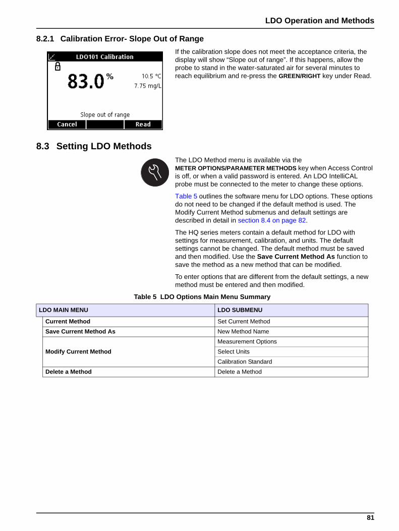
LDO Operation and Methods
8.2.1 Calibration Error- Slope Out of RangeIf the calibration slope does not meet the acceptance criteria, the display will show “Slope out of range”. If this happens, allow the probe to stand in the water-saturated air for several minutes to reach equilibrium and re-press the GREEN/RIGHT key under Read.
8.3 Setting LDO MethodsThe LDO Method menu is available via the METER OPTIONS/PARAMETER METHODS key when Access Control is off, or when a valid password is entered. An LDO IntelliCAL probe must be connected to the meter to change these options.
Table 5 outlines the software menu for LDO options. These options do not need to be changed if the default method is used. The Modify Current Method submenus and default settings are described in detail in section 8.4 on page 82.
The HQ series meters contain a default method for LDO with settings for measurement, calibration, and units. The default settings cannot be changed. The default method must be saved and then modified. Use the Save Current Method As function to save the method as a new method that can be modified.
To enter options that are different from the default settings, a new method must be entered and then modified.
Table 5 LDO Options Main Menu Summary
LDO MAIN MENU LDO SUBMENU
Current Method Set Current Method
Save Current Method As New Method Name
Modify Current MethodMeasurement Options
Select Units
Calibration Standard
Delete a Method Delete a Method
81
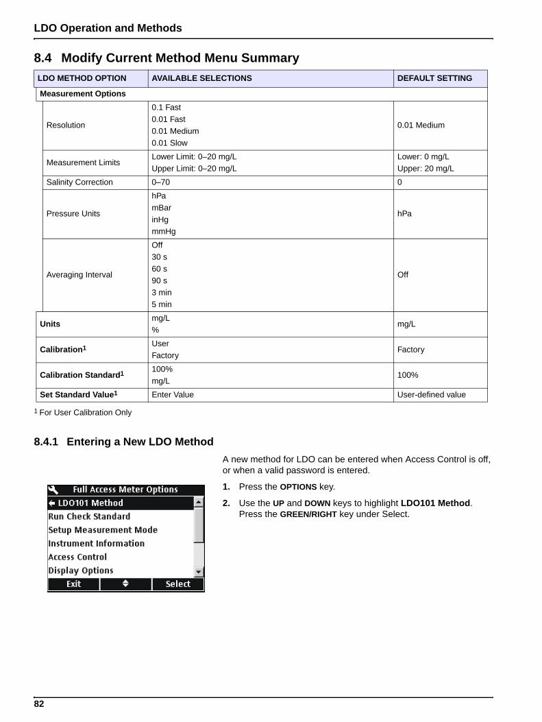
LDO Operation and Methods
8.4.1 Entering a New LDO MethodA new method for LDO can be entered when Access Control is off, or when a valid password is entered.
1. Press the OPTIONS key.
2. Use the UP and DOWN keys to highlight LDO101 Method. Press the GREEN/RIGHT key under Select.
8.4 Modify Current Method Menu SummaryLDO METHOD OPTION AVAILABLE SELECTIONS DEFAULT SETTING
Measurement Options
Resolution
0.1 Fast
0.01 Fast
0.01 Medium
0.01 Slow
0.01 Medium
Measurement LimitsLower Limit: 0–20 mg/LUpper Limit: 0–20 mg/L
Lower: 0 mg/LUpper: 20 mg/L
Salinity Correction 0–70 0
Pressure Units
hPa
mBar
inHgmmHg
hPa
Averaging Interval
Off
30 s
60 s90 s
3 min
5 min
Off
Unitsmg/L %
mg/L
Calibration1 User
FactoryFactory
Calibration Standard1 100%
mg/L100%
Set Standard Value1 Enter Value User-defined value
1 For User Calibration Only
82
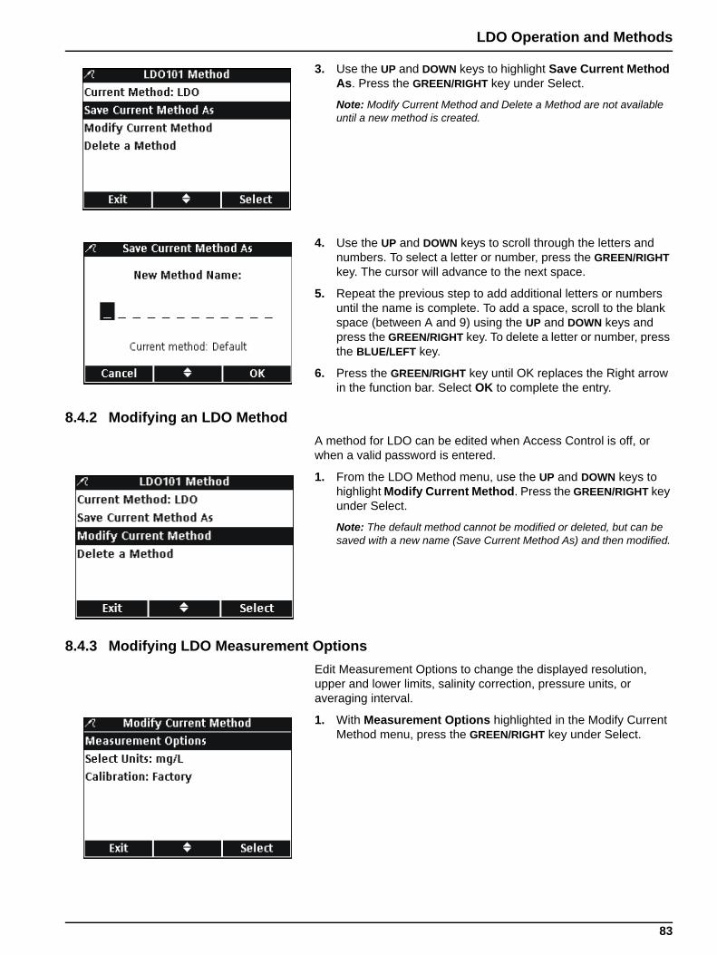
LDO Operation and Methods
3. Use the UP and DOWN keys to highlight Save Current Method As. Press the GREEN/RIGHT key under Select.
Note: Modify Current Method and Delete a Method are not available until a new method is created.
4. Use the UP and DOWN keys to scroll through the letters and numbers. To select a letter or number, press the GREEN/RIGHT key. The cursor will advance to the next space.
5. Repeat the previous step to add additional letters or numbers until the name is complete. To add a space, scroll to the blank space (between A and 9) using the UP and DOWN keys and press the GREEN/RIGHT key. To delete a letter or number, press the BLUE/LEFT key.
6. Press the GREEN/RIGHT key until OK replaces the Right arrow in the function bar. Select OK to complete the entry.
8.4.2 Modifying an LDO MethodA method for LDO can be edited when Access Control is off, or when a valid password is entered.
1. From the LDO Method menu, use the UP and DOWN keys to highlight Modify Current Method. Press the GREEN/RIGHT key under Select.
Note: The default method cannot be modified or deleted, but can be saved with a new name (Save Current Method As) and then modified.
8.4.3 Modifying LDO Measurement OptionsEdit Measurement Options to change the displayed resolution, upper and lower limits, salinity correction, pressure units, or averaging interval.
1. With Measurement Options highlighted in the Modify Current Method menu, press the GREEN/RIGHT key under Select.
83
LDO Operation and Methods
Changing Resolution1. With Resolution highlighted, press the GREEN/RIGHT key
under Select.
2. Use the UP and DOWN keys to select the desired resolution and speed of response. Press the GREEN/RIGHT key under OK.
Changing Measurement Limits1. Use the UP and DOWN keys to select Measurement Limits.
Press the GREEN/RIGHT key under Select.
2. Use the UP and DOWN keys to select Lower Limit or Upper Limit. Press the GREEN/RIGHT key under Select.
3. Lower Limit: Use the UP and DOWN keys to change the limit value. Use the BLUE/LEFT key to move to the left. Use the GREEN/RIGHT key to move to the right. When the cursor is at the far right, press the GREEN/RIGHT key under OK.
84
LDO Operation and Methods
4. Upper Limit: Use the UP and DOWN keys to change the limit value. Use the BLUE/LEFT key to move to the left. Use the GREEN/RIGHT key to move to the right. When the cursor is at the far right, press the GREEN/RIGHT key under OK.
Changing Salinity CorrectionCorrect dissolved oxygen values for high concentrations of dissolved salts by entering the sample salinity. Use a conductivity probe to measure the salinity.
1. Use the UP and DOWN keys to enter the sample salinity/salinity correction factor. Use the BLUE/LEFT key to move to the left. Use the GREEN/RIGHT key to move to the right. When the cursor is at the far right, press the GREEN/RIGHT key under OK.
Changing Pressure Units1. Use the UP and DOWN keys to select the desired pressure
units. Press the GREEN/RIGHT key under OK.
Changing the Averaging IntervalIn samples containing a high amount of air bubbles such as aeration basins, results will appear unstable or noisy. Use the averaging function to improve stability.
To select the interval for averaging results:
1. Use the UP and DOWN keys to select the desired Averaging Interval. Press the GREEN/RIGHT key under OK.
Displayed results will be averaged over the selected interval.
2. Whenever the average function is enabled, the averaging icon ( ) will be displayed along with the averaging interval.x
85
LDO Operation and Methods
8.4.4 Modifying the LDO Measurement UnitsThe meter will display both mg/L DO and % saturation in the measurement mode. To change which unit is prominent:
1. Use the UP and DOWN keys to highlight Select Units. Press the GREEN/RIGHT key under Select.
2. Use the UP and DOWN keys to select the units. Press the GREEN/RIGHT key under OK.
8.4.5 Modifying the LDO Calibration StandardImportant Note: Factory calibration is the default setting. Factory calibration coefficients are stored in the iButton.
Each lot of LDO sensor caps is factory calibrated. Performance will vary slightly as a function of usage history. For best performance, a one-time calibration initialization can be performed when a new sensor is installed. Additional calibrations can be performed at the operator's discretion but are not required. See section 8.2 on page 79 for calibration instructions.
8.4.5.1 Selecting Water-Saturated Air as the Calibration StandardTo use water-saturated air as the calibration standard:
1. Use the UP and DOWN keys to highlight Calibration Standard in the Modify Current Method menu. Press the GREEN/RIGHT key under Select.
86

LDO Operation and Methods
2. Use the UP and DOWN keys to select 100%. Press the GREEN/RIGHT key under OK.
8.4.5.2 Selecting a Water Sample as the Calibration StandardWater-saturated air is recommended for calibration of the HQ series meters, however a water sample with a known dissolved oxygen concentration can also be used. The dissolved oxygen concentration must be determined by Winkler titration, or by calculation of a saturated-air water sample using existing pressure, temperature, and salinity conditions.
1. Use the UP and DOWN keys to highlight Calibration Standard in the Modify Current Method menu. Press the GREEN/RIGHT key under Select.
2. Use the UP and DOWN keys to select mg/L. Press the GREEN/RIGHT key under OK.
When using a water sample as the calibration standard, a default value of 7.00 mg/L is used. Change the standard value to the exact concentration determined for the sample as follows:
3. Use the UP and DOWN keys to select Set Standard Value. Press the GREEN/RIGHT key under Select.
87

LDO Operation and Methods
4. Use the UP and DOWN keys to change the standard value. Use the BLUE/LEFT key to move to the left. Use the GREEN/RIGHT key to move to the right. When the cursor is at the far right, press the GREEN/RIGHT key under OK.
8.4.6 Selecting a LDO MethodSelect which method to use when additional methods have been entered in the LDO Options menu.
1. Use the UP and DOWN keys to highlight Current Method. Press the GREEN/RIGHT key under Select.
2. Use the UP and DOWN keys to select the desired method. Press the GREEN/RIGHT key under OK.
88
LDO Operation and Methods
8.4.7 Deleting a MethodTo delete an existing LDO method:
1. Use the UP and DOWN keys to highlight Delete a Method. Press the GREEN/RIGHT key under Select.
2. Use the UP and DOWN keys to select the desired method. Press the GREEN/RIGHT key under Delete. Once a method has been deleted, it cannot be recovered.
89
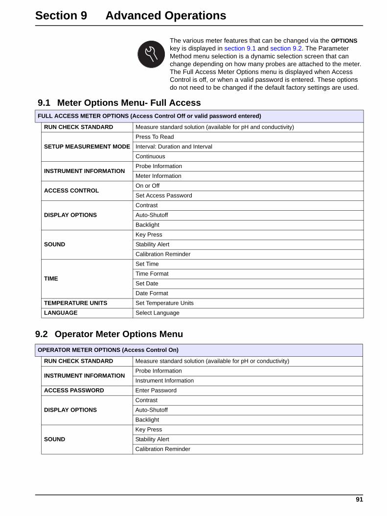
Section 9 Advanced Operations
The various meter features that can be changed via the OPTIONS key is displayed in section 9.1 and section 9.2. The Parameter Method menu selection is a dynamic selection screen that can change depending on how many probes are attached to the meter. The Full Access Meter Options menu is displayed when Access Control is off, or when a valid password is entered. These options do not need to be changed if the default factory settings are used.
9.2 Operator Meter Options Menu
9.1 Meter Options Menu- Full AccessFULL ACCESS METER OPTIONS (Access Control Off or valid password entered)
RUN CHECK STANDARD Measure standard solution (available for pH and conductivity)
SETUP MEASUREMENT MODEPress To Read
Interval: Duration and Interval
Continuous
INSTRUMENT INFORMATIONProbe Information
Meter Information
ACCESS CONTROLOn or Off
Set Access Password
DISPLAY OPTIONSContrast
Auto-Shutoff
Backlight
SOUNDKey Press
Stability Alert
Calibration Reminder
TIME
Set Time
Time Format
Set Date
Date Format
TEMPERATURE UNITS Set Temperature Units
LANGUAGE Select Language
OPERATOR METER OPTIONS (Access Control On)
RUN CHECK STANDARD Measure standard solution (available for pH or conductivity)
INSTRUMENT INFORMATIONProbe Information
Instrument Information
ACCESS PASSWORD Enter Password
DISPLAY OPTIONSContrast
Auto-Shutoff
Backlight
SOUNDKey Press
Stability Alert
Calibration Reminder
91
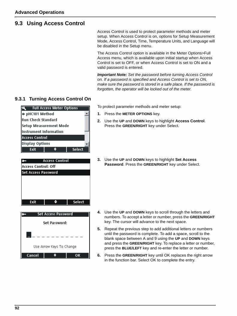
Advanced Operations
9.3 Using Access ControlAccess Control is used to protect parameter methods and meter setup. When Access Control is on, options for Setup Measurement Mode, Access Control, Time, Temperature Units, and Language will be disabled in the Setup menu.
The Access Control option is available in the Meter Options>Full Access menu, which is available upon initial startup when Access Control is set to OFF, or when Access Control is set to ON and a valid password is entered.
Important Note: Set the password before turning Access Control on. If a password is specified and Access Control is set to ON, make sure the password is stored in a safe place. If the password is forgotten, the operator will be locked out of the meter.
9.3.1 Turning Access Control OnTo protect parameter methods and meter setup:
1. Press the METER OPTIONS key.
2. Use the UP and DOWN keys to highlight Access Control. Press the GREEN/RIGHT key under Select.
3. Use the UP and DOWN keys to highlight Set Access Password. Press the GREEN/RIGHT key under Select.
4. Use the UP and DOWN keys to scroll through the letters and numbers. To accept a letter or number, press the GREEN/RIGHT key. The cursor will advance to the next space.
5. Repeat the previous step to add additional letters or numbers until the password is complete. To add a space, scroll to the blank space between A and 9 using the UP and DOWN keys and press the GREEN/RIGHT key. To replace a letter or number, press the BLUE/LEFT key and re-enter the letter or number.
6. Press the GREEN/RIGHT key until OK replaces the right arrow in the function bar. Select OK to complete the entry.
92
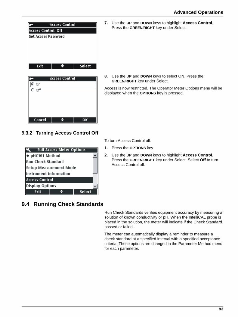
Advanced Operations
7. Use the UP and DOWN keys to highlight Access Control. Press the GREEN/RIGHT key under Select.
8. Use the UP and DOWN keys to select ON. Press the GREEN/RIGHT key under Select.
Access is now restricted. The Operator Meter Options menu will be displayed when the OPTIONS key is pressed.
9.3.2 Turning Access Control OffTo turn Access Control off:
1. Press the OPTIONS key.
2. Use the UP and DOWN keys to highlight Access Control. Press the GREEN/RIGHT key under Select. Select Off to turn Access Control off.
9.4 Running Check StandardsRun Check Standards verifies equipment accuracy by measuring a solution of known conductivity or pH. When the IntelliCAL probe is placed in the solution, the meter will indicate if the Check Standard passed or failed.
The meter can automatically display a reminder to measure a check standard at a specified interval with a specified acceptance criteria. These options are changed in the Parameter Method menu for each parameter.
93
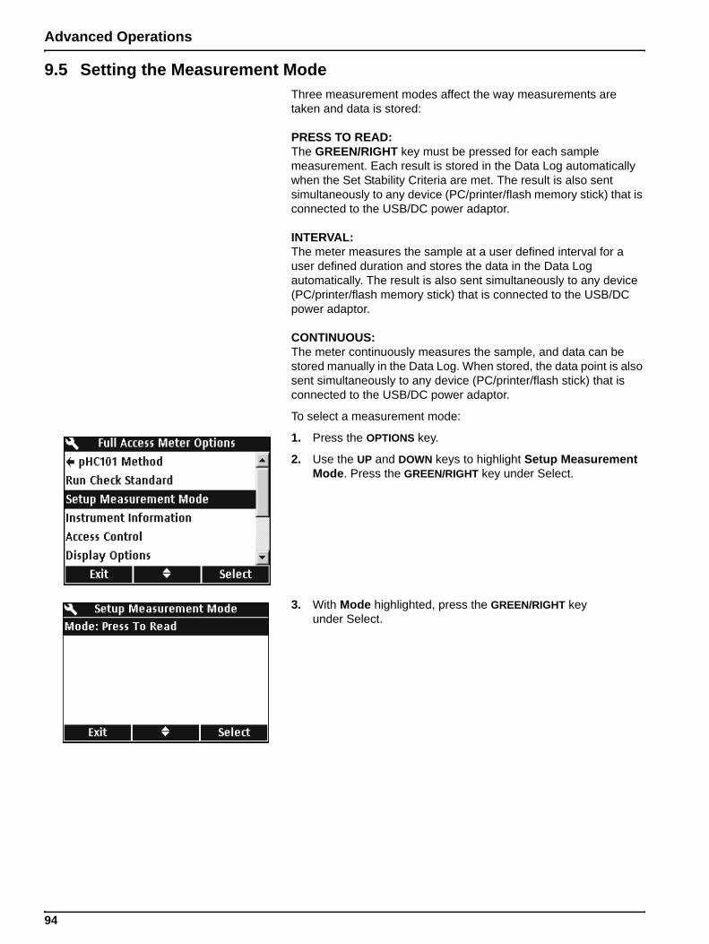
Advanced Operations
9.5 Setting the Measurement ModeThree measurement modes affect the way measurements are taken and data is stored:
PRESS TO READ: The GREEN/RIGHT key must be pressed for each sample measurement. Each result is stored in the Data Log automatically when the Set Stability Criteria are met. The result is also sent simultaneously to any device (PC/printer/flash memory stick) that is connected to the USB/DC power adaptor.
INTERVAL: The meter measures the sample at a user defined interval for a user defined duration and stores the data in the Data Log automatically. The result is also sent simultaneously to any device (PC/printer/flash memory stick) that is connected to the USB/DC power adaptor.
CONTINUOUS: The meter continuously measures the sample, and data can be stored manually in the Data Log. When stored, the data point is also sent simultaneously to any device (PC/printer/flash stick) that is connected to the USB/DC power adaptor.
To select a measurement mode:
1. Press the OPTIONS key.
2. Use the UP and DOWN keys to highlight Setup Measurement Mode. Press the GREEN/RIGHT key under Select.
3. With Mode highlighted, press the GREEN/RIGHT key under Select.
94
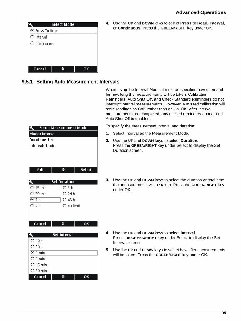
Advanced Operations
4. Use the UP and DOWN keys to select Press to Read, Interval, or Continuous. Press the GREEN/RIGHT key under OK.
9.5.1 Setting Auto Measurement IntervalsWhen using the Interval Mode, it must be specified how often and for how long the measurements will be taken. Calibration Reminders, Auto Shut Off, and Check Standard Reminders do not interrupt interval measurements. However, a missed calibration will store readings as Cal? rather than as Cal OK. After interval measurements are completed, any missed reminders appear and Auto Shut Off is enabled.
To specify the measurement interval and duration:
1. Select Interval as the Measurement Mode.
2. Use the UP and DOWN keys to select Duration. Press the GREEN/RIGHT key under Select to display the Set Duration screen.
3. Use the UP and DOWN keys to select the duration or total time that measurements will be taken. Press the GREEN/RIGHT key under OK.
4. Use the UP and DOWN keys to select Interval. Press the GREEN/RIGHT key under Select to display the Set Interval screen.
5. Use the UP and DOWN keys to select how often measurements will be taken. Press the GREEN/RIGHT key under OK.
95
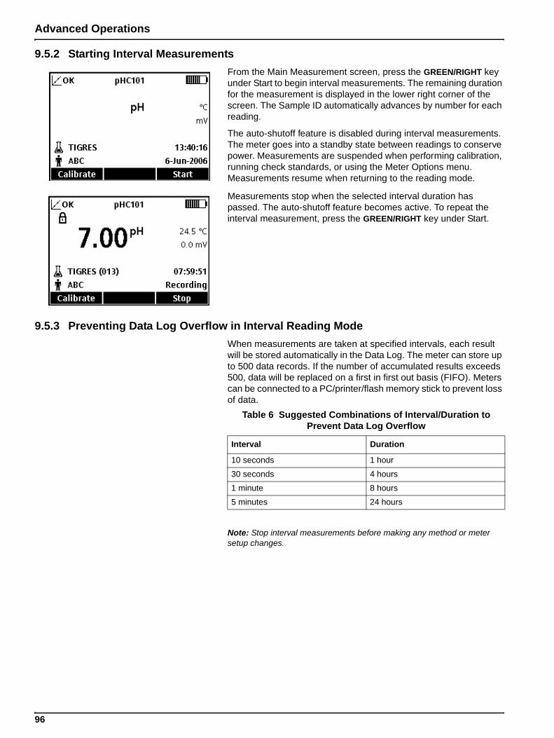
Advanced Operations
9.5.2 Starting Interval MeasurementsFrom the Main Measurement screen, press the GREEN/RIGHT key under Start to begin interval measurements. The remaining duration for the measurement is displayed in the lower right corner of the screen. The Sample ID automatically advances by number for each reading.
The auto-shutoff feature is disabled during interval measurements. The meter goes into a standby state between readings to conserve power. Measurements are suspended when performing calibration, running check standards, or using the Meter Options menu. Measurements resume when returning to the reading mode.
Measurements stop when the selected interval duration has passed. The auto-shutoff feature becomes active. To repeat the interval measurement, press the GREEN/RIGHT key under Start.
9.5.3 Preventing Data Log Overflow in Interval Reading ModeWhen measurements are taken at specified intervals, each result will be stored automatically in the Data Log. The meter can store up to 500 data records. If the number of accumulated results exceeds 500, data will be replaced on a first in first out basis (FIFO). Meters can be connected to a PC/printer/flash memory stick to prevent loss of data.
Note: Stop interval measurements before making any method or meter setup changes.
Table 6 Suggested Combinations of Interval/Duration to Prevent Data Log Overflow
Interval Duration
10 seconds 1 hour
30 seconds 4 hours
1 minute 8 hours
5 minutes 24 hours
96
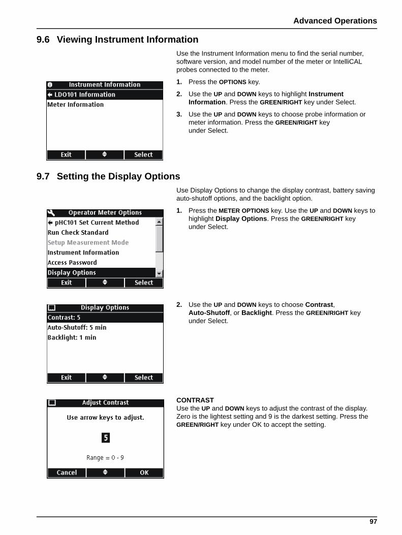
Advanced Operations
9.6 Viewing Instrument InformationUse the Instrument Information menu to find the serial number, software version, and model number of the meter or IntelliCAL probes connected to the meter.
1. Press the OPTIONS key.
2. Use the UP and DOWN keys to highlight Instrument Information. Press the GREEN/RIGHT key under Select.
3. Use the UP and DOWN keys to choose probe information or meter information. Press the GREEN/RIGHT key under Select.
9.7 Setting the Display OptionsUse Display Options to change the display contrast, battery saving auto-shutoff options, and the backlight option.
1. Press the METER OPTIONS key. Use the UP and DOWN keys to highlight Display Options. Press the GREEN/RIGHT key under Select.
2. Use the UP and DOWN keys to choose Contrast, Auto-Shutoff, or Backlight. Press the GREEN/RIGHT key under Select.
CONTRAST Use the UP and DOWN keys to adjust the contrast of the display. Zero is the lightest setting and 9 is the darkest setting. Press the GREEN/RIGHT key under OK to accept the setting.
97
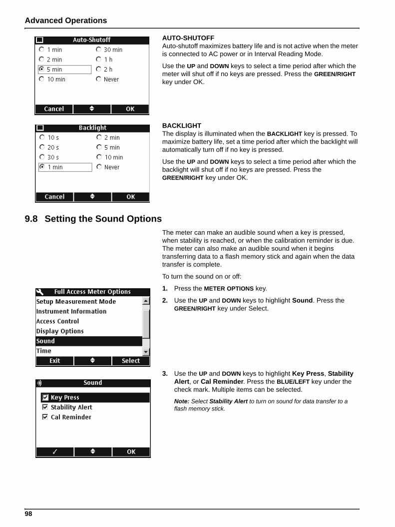
Advanced Operations
AUTO-SHUTOFFAuto-shutoff maximizes battery life and is not active when the meter is connected to AC power or in Interval Reading Mode.
Use the UP and DOWN keys to select a time period after which the meter will shut off if no keys are pressed. Press the GREEN/RIGHT key under OK.
BACKLIGHTThe display is illuminated when the BACKLIGHT key is pressed. To maximize battery life, set a time period after which the backlight will automatically turn off if no key is pressed.
Use the UP and DOWN keys to select a time period after which the backlight will shut off if no keys are pressed. Press the GREEN/RIGHT key under OK.
9.8 Setting the Sound OptionsThe meter can make an audible sound when a key is pressed, when stability is reached, or when the calibration reminder is due. The meter can also make an audible sound when it begins transferring data to a flash memory stick and again when the data transfer is complete.
To turn the sound on or off:
1. Press the METER OPTIONS key.
2. Use the UP and DOWN keys to highlight Sound. Press the GREEN/RIGHT key under Select.
3. Use the UP and DOWN keys to highlight Key Press, Stability Alert, or Cal Reminder. Press the BLUE/LEFT key under the check mark. Multiple items can be selected.
Note: Select Stability Alert to turn on sound for data transfer to a flash memory stick.
98
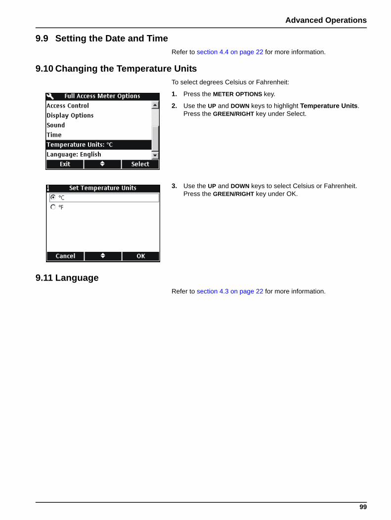
Advanced Operations
9.9 Setting the Date and TimeRefer to section 4.4 on page 22 for more information.
9.10 Changing the Temperature UnitsTo select degrees Celsius or Fahrenheit:
1. Press the METER OPTIONS key.
2. Use the UP and DOWN keys to highlight Temperature Units. Press the GREEN/RIGHT key under Select.
3. Use the UP and DOWN keys to select Celsius or Fahrenheit. Press the GREEN/RIGHT key under OK.
9.11 LanguageRefer to section 4.3 on page 22 for more information.
99
Section 10 Maintenance
DANGEROnly qualified personnel should conduct the tasks described in this section of the manual.
10.1 General Meter CleaningThe meter is designed to be maintenance-free. If the meter is dirty, wipe the surface with a damp cloth. Use a cotton-tipped applicator to clean or dry the connectors if they get wet.
10.2 General Probe CleaningFor information about cleaning the probes, see the instruction sheet that comes with the IntelliCAL probe.
10.3 Battery ReplacementSee section 3.2 on page 12.
10.4 Updating Instrument SoftwareFrom time to time Hach Company may release updates to the meter software. A flash stick connected to the USB/DC power adapter can be used to update the instrument software or transfer data from the instrument.
Note: The manufacturer will determine if an update to the software is necessary to make sure that the HQd Series correctly functions.
101
Section 11 Parts and Accessories
11.1 PartsDescription Quantity Catalog Number
LDO Probe, standard, with 1 m cable 1 LDO101-01
LDO Probe, standard, with 3 m cable 1 LDO101-03
LDO Probe, rugged, with 5 m cable 1 LDO101-05
LDO Probe, rugged, with 10 m cable 1 LDO101-10
LDO Probe, rugged, with 15 m cable 1 LDO101-15
LDO Probe, rugged, with 30 m cable 1 LDO101-30
pH Gel Probe, standard, with 1m cable 1 PHC101-01
pH Gel Probe, standard, with 3m cable 1 PHC101-03
pH Liquid Probe, standard, with 1m cable 1 PHC301-01
pH Liquid Probe, standard, with 3m cable 1 PHC301-03
pH Gel Probe, rugged, with 5m cable 1 PHC101-05
pH Gel Probe, rugged, with 10m cable 1 PHC101-10
pH Gel Probe, rugged, with 15m cable 1 PHC101-15
pH Gel Probe, rugged, with 30m cable 1 PHC101-30
Conductivity Probe, standard with 1m cable 1 CDC401-01
Conductivity Probe, standard with 3m cable 1 CDC401-03
Conductivity Probe, rugged with 5m cable 1 CDC401-05
Conductivity Probe, rugged with 10m cable 1 CDC401-10
Conductivity Probe, rugged with 15m cable 1 CDC401-15
Conductivity Probe, rugged with 30m cable 1 CDC401-30
11.2 AccessoriesDescription Quantity Catalog Number
Probe Depth Marker (Rugged Cable Markers) 5 58286-10
LDO Sensor Cap, Replacement (includes iButton, cap seal, and probe-tip o-ring) 1 58112-00
Glove Kit 1 58287-00
Field Kit 1 52258-00
Standard Probe Holder 1 58294-00
Rugged Shroud Kit 1 58259-00
Color Coded Probe Clips (five colors, two clips in each color) 1 58184-00
AC Power Adapter Kit, 115 VAC 1 58263-00
AC Power Adapter Kit, 230 VAC 1 58311-00
Batteries, Alkaline AA 4/pkg 19380-04
USB/DC Power Adapter 1 58134-00
USB Cable, 6 ft. (1.8 m), Type A Male, Type B Male 1 59240-00
Keyboard (QWERTY) 1 LZV582
BOD Bottle (300 mL) 1 621-00
BOD Stirrer/Funnel Accessory Kit (US) 1 58266-00
BOD Stirrer/Funnel Accessory Kit (EU) 1 58267-00
Software for direct connection to PC 1 HQ40d45
103
Parts and Accessories
11.3 ConsumablesDescription Quantity Catalog Number
IUPAC Series Certified pH Standards (Buffers)1:
pH 1.679 ± 0.010 @ 25 °C 500 mL S11M001
pH 4.005 ± 0.010 @ 25 °C 500 mL S11M002
pH 7.000 (Radiometer Analytical) ± 0.010 @ 25 °C 500 mL S11M004
pH 10.012 ± 0.010 @ 25 °C 500 mL S11M007
pH 12.45 ± 0.05 @ 25 °C 500 mL S11M008
Color-coded pH Standards (Buffers):
pH 4.01 ±0.02 @ 25 °C 500 mL 22834-49
pH 7.00 ±0.02 @ 25 °C 500 mL 22835-49
pH 10.01 ±0.02 @ 25 °C 500 mL 22836-49
pH 4.01 ±0.02 @ 25 °C 4 L 22834-56
pH 7.00 ±0.02 @ 25 °C 4 L 22835-56
pH 10.01 ±0.02 @ 25 °C 4 L 22836-56
pH 4.01 ±0.02 @ 25 °C 20 L 22834-61
pH 7.00 ±0.02 @ 25 °C 20 L 22835-61
pH 10.01 ±0.02 @ 25 °C 20 L 22836-61
Certified Conductivity Standards1:
KCl, 1 Demal, 111.3 mS/cm ± 0.5% @ 25 °C 500 mL S51M001
KCl, 0.1 Demal, 12.85 mS/cm ± 0.35% @ 25 °C 500 mL S51M002
KCl, 0.01 Demal, 1408 µS/cm ± 0.5% @ 25 °C 500 mL S51M003
NaCl, 0.05%, 1015 µS/cm ± 0.5% @ 25 °C 500 mL S51M004
KCl Conductivity Standards:
0.1 Molar KCl, 12.88 mS/cm @ 25 °C 500 mL C20C250
0.01 Molar KCl, 1413 µS/cm @ 25 °C 500 mL C20C270
0.001 Molar KCl, 148 µS/cm @ 25 °C 500 mL C20C280
NaCl Conductivity Standards:
180 µS/cm @ 25 °C 100 mL 23075-42
1000 µS/cm @ 25 °C 100 mL 14400-42
18.00 mS/cm @ 25 °C 100 mL 23074-42
BOD Consumables:
Nitrification Inhibitor (TCMP) - (200 tests) 35 g 2533-35
Nitrification inhibitor (TCMP) - (2500 tests) 500 g 2533-34
Nitrification Inhibitor (ATU) 50 g 28454-25
BOD Seed (50 tests) 50 capsules 24712-00
BOD Standard Solution, 300 mg/L GGA, 10-mL Voluette® Ampules 25/pkg 14865-10
Nutrient Buffer Pillow, 0.5 mL (for preparing 300 mL of dilution water) 50/pkg 14160-66
Nutrient Buffer Pillow, 3 mL (for preparing 3 L of dilution water) 50/pkg 14861-66
Nutrient Buffer Pillow, 4 mL (for preparing 4 L of dilution water) 50/pkg 24364-66
Nutrient Buffer Pillow, 6 mL (for preparing 6 L of dilution water) 50/pkg 14862-66
Nutrient Buffer Pillow, 19 mL (for preparing 19 L of dilution water) 25/pkg 14863-98
Buffer Solution, APHA, for BOD, pH 7.2, phosphate type 1 L 431-53
Calcium Chloride Solution, APHA 1 L 428-53
104
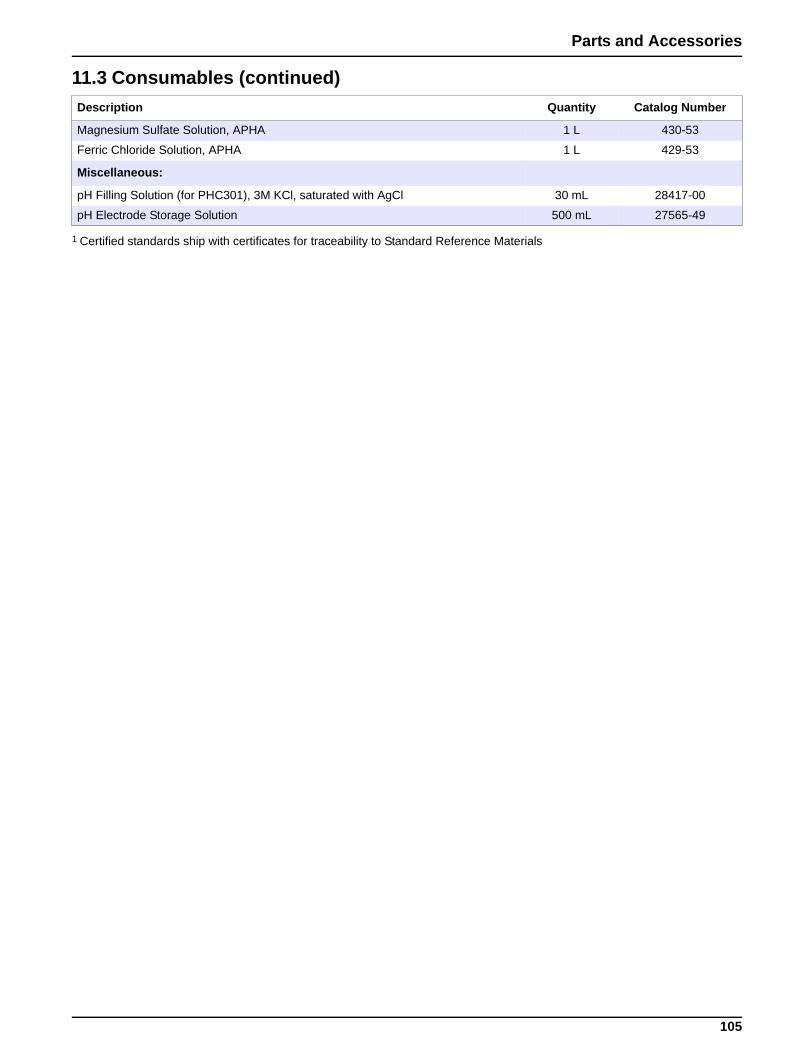
Parts and Accessories
Magnesium Sulfate Solution, APHA 1 L 430-53
Ferric Chloride Solution, APHA 1 L 429-53
Miscellaneous:
pH Filling Solution (for PHC301), 3M KCl, saturated with AgCl 30 mL 28417-00
pH Electrode Storage Solution 500 mL 27565-49
1 Certified standards ship with certificates for traceability to Standard Reference Materials
11.3 Consumables (continued)Description Quantity Catalog Number
105
Section 12 How to Order
U.S.A. CustomersBy Telephone:6:30 a.m. to 5:00 p.m. MSTMonday through Friday(800) 227-HACH (800-227-4224)
By Fax:(970) 669-2932
By Mail:Hach CompanyP.O. Box 389Loveland, Colorado 80539-0389 U.S.A.
By E-mail:[email protected]
Information Required
International CustomersHach maintains a worldwide network of dealers and distributors. To locate the representative nearest you, send an e-mail to: [email protected] or contact:
Hach Company World Headquarters; Loveland, Colorado, U.S.A.Telephone: (970) 669-3050; Fax: (970) 669-2932
Technical and Customer Service (U.S.A. only)Hach Technical and Customer Service Department personnel are eager to answer questions about our products and their use. Specialists in analytical methods, they are happy to put their talents to work for you.
Call 1-800-227-4224 or e-mail [email protected]
• Hach account number (if available) • Billing address
• Your name and phone number • Shipping address
• Purchase order number • Catalog number
• Brief description or model number • Quantity
107
Section 13 Repair Service
Authorization must be obtained from Hach Company before sending any items for repair. Please contact the Hach Service Center serving your location.
In the United States:Hach CompanyAmes Service100 Dayton AvenueAmes, Iowa 50010(800) 227-4224 (U.S.A. only)FAX: (515) 232-3835
In Canada:Hach Sales & Service Canada Ltd.1313 Border Street, Unit 34Winnipeg, ManitobaR3H 0X4(800) 665-7635 (Canada only)Telephone: (204) 632-5598FAX: (204) 694-5134E-mail: [email protected]
In Latin America, the Caribbean, the Far East,Indian Subcontinent, Africa, Europe, or the Middle East:Hach Company World Headquarters,P.O. Box 389Loveland, Colorado, 80539-0389 U.S.A.Telephone: (970) 669-3050FAX: (970) 669-2932E-mail: [email protected]
109
Section 14 Certification
Hach Company certifies this instrument was tested thoroughly, inspected and found to meet its published specifications when it was shipped from the factory.
The HQ Series Portable Meters have been tested and are certified as indicated to the following instrumentation standards:
Product Safety (power supply only)115/230 VAC External Power Supply
Certified to CSA and Listed to UL safety standards (cULus mark), TUV-GS & CE marked per 73/23/EEC
EMI ImmunityInstrument tested with the external Power Supply:
Per 89/336/EEC EMC: EN 61326:1998 (Electrical Equipment for measurement, control and laboratory use— EMC requirements) Supporting test records by Hach Company, certified compliance by Hach Company.
Standards include:IEC 1000-4-2:1995 (EN 61000-4-2:1995) Electro-Static Discharge Immunity (Criteria B)
IEC 1000-4-3:1995 (EN 61000-4-3:1996) Radiated RF Electro-Magnetic Field Immunity (Criteria B)
IEC 1000-4-4:1995 (EN 61000-4-5:1995) Electrical Fast Transients/Burst (Criteria B)
IEC 1000-4-5:1995 (EN 61000-4-5:1995) Surge (Criteria B)
IEC 1000-4-6:1996 (EN 61000-4-6:1996) Conducted Disturbances Induced by RF Fields (Criteria A)
IEC 1000-4-11:1994 (EN 61000-4-11:1994) Voltage Dip/Short Interruptions (Criteria B)
Additional immunity Standard/s include:
ENV 50204:1996 Radiated Electro-Magnetic Field from Digital Telephones (Criteria B)
EmissionsInstrument tested with the external Power Supply:
Per 89/336/EEC EMC: EN 61326:1998 (Electrical Equipment for measurement, control and laboratory use—EMC requirements) Class “B” emission limits all models except HQ40D Multi-Portable Meter with “2” LDO probes. The HQ40D when used with “2” LDO probes meets only Class “A” limits. Supporting test records by Hewlett Packard, Fort Collins, Colorado Hardware Test Center (A2LA # 0905-01) and certified compliance by Hach Company.
Standards include:EN 61000-3-2 Harmonic Disturbances Caused by Electrical Equipment
EN 61000-3-3 Voltage Fluctuation (Flicker) Disturbances Caused by Electrical Equipment
111

Certification
Additional Emissions Standard/s includeEN 55011 (CISPR 11), Class “B” emission limits all models except HQ40D Multi-Portable Meter with “2” LDO probes. The HQ40D when used with “2” LDO probes meets only Class “A” limits.
CANADIAN INTERFERENCE-CAUSING EQUIPMENT REGULATIONIECS-003: Class “A” emission limits. Supporting test records by Hewlett Packard, Fort Collins, Colorado Hardware Test Center (A2LA # 0905-01) and certified compliance by Hach Company.
This Class “A” digital apparatus meets all requirements of the Canadian Interference- Causing Equipment Regulations.
Cet appareil numérique de la classe “A” respecte toutes les exigences du Règlement sur le matériel brouilleur du Canada.
FCC PART 15: Class emission A limits Supporting test records by Hewlett Packard, Fort Collins, Colorado Hardware Test Center (A2LA # 0905-01) and certified compliance by Hach Company.
This device complies with Part 15 of the FCC Rules. Operation is subject to the following two conditions:
(1) this device may not cause harmful interference, and (2) this device must accept any interference received, including interference that may cause undesired operation.
Changes or modifications to this unit not expressly approved by the party responsible for compliance could void the user's authority to operate the equipment.
This equipment has been tested and found to comply with the limits for a Class “A” digital device, pursuant to Part 15 of the FCC Rules. These limits are designed to provide reasonable protection against harmful interference when the equipment is operated in a commercial environment. This equipment generates, uses, and can radiate radio frequency energy and, if not installed and used in accordance with the instruction manual, may cause harmful interference to radio communications. Operation of this equipment in a residential area is likely to cause harmful interference, in which case the user will be required to correct the interference at their own expense. The following techniques of reducing the interference problems are applied easily.
1. Disconnect the external power supply from the meter and/or remove one of the meter’s batteries to verify that meter is or is not the source of the interference.
2. Move the meter and it’s power supply away from the device receiving the interference.
3. Reposition the receiving antenna for the device receiving the interference.
4. Try combinations of the above.
112
Section 15 Limited Warranty
Hach Company warrants its products to the original purchaser against any defects that are due to faulty material or workmanship for a period of one year from date of shipment unless otherwise noted in the product manual.
In the event that a defect is discovered during the warranty period, Hach Company agrees that, at its option, it will repair or replace the defective product or refund the purchase price excluding original shipping and handling charges. Any product repaired or replaced under this warranty will be warranted only for the remainder of the original product warranty period.
This warranty does not apply to consumable products such as chemical reagents; or consumable components of a product, such as, but not limited to, lamps and tubing.
Contact Hach Company or your distributor to initiate warranty support. Products may not be returned without authorization from Hach Company.
LimitationsThis warranty does not cover:
• Damage caused by acts of God, natural disaster, labor unrest, acts of war (declared or undeclared), terrorism, civil strife or acts of any governmental jurisdiction
• Damage caused by misuse, neglect, accident or improper application or installation
• Damage caused by any repair or attempted repair not authorized by Hach Company
• Any product not used in accordance with the instructions furnished by Hach Company
• Freight charges to return merchandise to Hach Company
• Freight charges on expedited or express shipment of warranted parts or product
• Travel fees associated with on-site warranty repair
This warranty contains the sole express warranty made by Hach Company in connection with its products. All implied warranties, including without limitation, the warranties of merchantability and fitness for a particular purpose, are expressly disclaimed.
Some states within the United States do not allow the disclaimer of implied warranties and if this is true in your state the above limitation may not apply to you. This warranty gives you specific rights, and you may also have other rights that vary from state to state.
This warranty constitutes the final, complete, and exclusive statement of warranty terms and no person is authorized to make any other warranties or representations on behalf of Hach Company.
Limitation of RemediesThe remedies of repair, replacement or refund of purchase price as stated above are the exclusive remedies for the breach of this warranty. On the basis of strict liability or under any other legal theory, in no event shall Hach Company be liable for any incidental or consequential damages of any kind for breach of warranty or negligence.
113
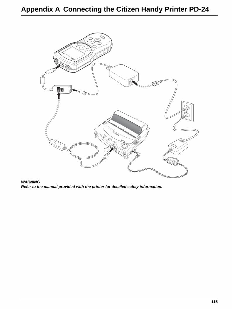
Appendix A Connecting the Citizen Handy Printer PD-24
WARNINGRefer to the manual provided with the printer for detailed safety information.
115
Index
AAC power supply ...................................................... 12Access Control
passwords ......................................................... 92turning off ........................................................... 93turning on ........................................................... 92
accessories ............................................................ 103auto-shutoff, batteries ........................................ 14, 98averaging interval, LDO methods ............................ 85
BBacklight options ...................................................... 98batteries
auto-shutoff .................................................. 14, 98features ................................................................ 8installing ............................................................. 12
beep options ............................................................ 98box contents ............................................................. 11
Ccables, part numbers ............................................. 103calibrating probes
conductivity ........................................................ 63LDO ................................................................... 79pH ...................................................................... 47Slope out of range error ............................... 48, 81Standard not recognized error ........................... 48
Calibration ................................................................ 41Calibration Log
displaying ........................................................... 29calibration options
conductivity .................................................. 67, 72LDO ................................................................... 86pH ...................................................................... 55
calibration reportsviewing ............................................................... 40
Canadian safety regulations .................................. 112Celsius, settings ....................................................... 99certification ............................................................. 111Check Standards
conductivity method options ........................ 67, 75deferring (conductivity) ...................................... 66deferring (pH) .................................................... 51log, displaying .................................................... 29pH method options ............................................ 59running manually or automatically (conductivity) 65running manually or automatically (pH) ............. 49settings .............................................................. 93
cleaning .................................................................. 101column headers ....................................................... 32components, unpacking ........................................... 11
computers, transferring data to ................................ 16conductivity
calibrating probe ................................................ 63deferring Check Standards ................................ 66measuring .......................................................... 64probe specifications ............................................. 9running Check Standards .................................. 65
conductivity methodscalibration options ........................................ 67, 72Check Standards options ............................ 67, 75limits .................................................................. 69measurement options .................................. 67, 69menu options ..................................................... 66modifying ........................................................... 68parameters ........................................................ 67parameters, changing ........................................ 68reference temperature ....................................... 71temperature correction ...................................... 70units ................................................................... 69
connectors, probe .................................................... 14contact information
ordering parts .................................................. 107repair service ................................................... 109support ............................................................. 107
Continuous measurement mode .............................. 94contrast, display ....................................................... 97Current ..................................................................... 40customer support ................................................... 107
Ddata
deleting .............................................................. 30overflow, preventing .......................................... 96viewing downloaded data files ........................... 42viewing probe .................................................... 29viewing stored .................................................... 28
data transferarchiving and exchanging methods ................... 45calibration data from probe ................................ 35computer ............................................................ 34features .............................................................. 16flash memory stick ............................................. 33formatting ........................................................... 31
date, setting ............................................................. 22deferring Check Standards
conductivity ........................................................ 66pH ...................................................................... 51
deletingmethods ............................................................. 89Operator ID ........................................................ 28Sample IDs ........................................................ 26stored data ......................................................... 30
117
Index
Display Options ........................................................ 97display screen .......................................................... 21dissolved oxygen, measuring ................................... 79
See also LDO methods; LDO probedownloading data
sending data to a computer ............................... 34sending data to a printer .................................... 33transferring calibration data ............................... 34viewing downloaded data files ........................... 42
dual display screen .................................................. 21
Ee-mail customer support ........................................ 107EMI Immunity ......................................................... 111Emissions Standards ............................................. 112end-of-life waste disposal .......................................... 7errors, probe calibration
Slope out of range ....................................... 48, 81Standard not recognized ................................... 48
European Union regulations ...................................... 7
FFahrenheit, settings ................................................. 99FCC statement ....................................................... 112features ...................................................................... 8flash sticks, transferring data to ............................... 16
Iinstalling batteries .................................................... 12Instrument Information, viewing ............................... 97Interval measurement mode
auto measurement intervals, setting .................. 95data log overflow ............................................... 96selecting ............................................................ 94starting measurements ...................................... 96
Kkey press options ..................................................... 98keypad ..................................................................... 20
Llabels, precautionary .................................................. 7language, selecting .................................................. 22
LDO methodsaveraging interval .............................................. 85calibration options .............................................. 86limits .................................................................. 84measurement options ........................................ 83modifying ........................................................... 83new, creating ..................................................... 82pressure units .................................................... 85resolution ........................................................... 84salinity correction ............................................... 85units ................................................................... 86
LDO probecalibrating .......................................................... 79measuring dissolved oxygen ............................. 79specifications ....................................................... 9
limitsconductivity ........................................................ 69LDO ................................................................... 84pH ...................................................................... 54
logsCalibration ......................................................... 29Check Standards ............................................... 29data overflow ..................................................... 96Reading ............................................................. 29
luminescent dissolved oxygen. See LDO methods; LDOprobe
Mmaintenance .......................................................... 101measurement modes, selecting ............................... 94measurement options
conductivity .................................................. 67, 69LDO ................................................................... 83pH ...................................................................... 53
measuringconductivity, salinity, resistivity, or TDS ............. 64dissolved oxygen ............................................... 79pH ...................................................................... 49
meter cleaning ....................................................... 101methods
archiving and exchanging .................................. 45deleting .............................................................. 89pH ...................................................................... 51selecting ............................................................ 88
model number .......................................................... 97models ....................................................................... 8
Oon/off key ................................................................. 14
118
Index
Operator IDcreating .............................................................. 27deleting .............................................................. 28displaying ........................................................... 26selecting ............................................................ 27
ordering parts ......................................................... 107overflow, data ........................................................... 96oxygen, measuring dissolved ................................... 79
See also LDO methods; LDO probe
Ppacking slip .............................................................. 11part number, AC power supply ................................ 12parts
numbers ........................................................... 103ordering ........................................................... 107
passwords, Access Control ...................................... 92PCs, transferring data to .......................................... 16pH
calibrating probe ................................................ 47deferring Check Standards ................................ 51measuring .......................................................... 49probe specifications ............................................. 9running Check Standards .................................. 49
pH methodscalibration options .............................................. 55Check Standard options .................................... 59creating new ...................................................... 51limits .................................................................. 54measurement options ........................................ 53modifying ........................................................... 53resolution ........................................................... 54units ................................................................... 62
phone numbersordering parts .................................................. 107repair service ................................................... 109support ............................................................. 107
power on/off key ....................................................... 14power requirements ................................................... 9power supply, AC ............................................. 12, 111Press to Read measurement mode ......................... 94pressure units, LDO methods .................................. 85printers, transferring data to ..................................... 16printing
sending data to a printer .................................... 33
probescalibrating conductivity ...................................... 63calibrating LDO .................................................. 79calibrating pH ..................................................... 47cleaning ........................................................... 101connectors ......................................................... 14display screen .................................................... 21Instrument Information ....................................... 97measuring conductivity, salinity, resistivity, or TDS
64measuring dissolved oxygen ............................. 79measuring pH .................................................... 49part numbers ................................................... 103Slope out of range error ............................... 48, 81specifications ....................................................... 9Standard not recognized error ........................... 48viewing data ....................................................... 29
RReading Log
displaying ........................................................... 29rechargeable batteries ............................................. 12recycling ..................................................................... 7reference temperature, conductivity methods .......... 71reminders, calibration
conductivity ........................................................ 72pH ...................................................................... 56
repair ...................................................................... 109report options ........................................................... 31resistivity, measuring ............................................... 64resolution
LDO methods .................................................... 84pH method ......................................................... 54
Run Check Standardsconductivity ........................................................ 65pH ...................................................................... 49settings .............................................................. 93
Ssafety information ............................................... 7, 111salinity
correction, LDO methods ................................... 85measuring .......................................................... 64
Sample IDcreating .............................................................. 25deleting .............................................................. 26Reading Log ...................................................... 29selecting ............................................................ 26
screen, display ......................................................... 21sending data
features .............................................................. 16to flash stick or printer ....................................... 31
119
Index
serial number ....................................................... 8, 97service .................................................................... 109single display screen ................................................ 21Slope out of range error ..................................... 48, 81softkeys .................................................................... 20software
updating ........................................................... 101sound options ........................................................... 98specifications ............................................................. 9Standard not recognized calibration error ................ 48standards. See Check Standardsstored data
deleting .............................................................. 30viewing ............................................................... 28
support ................................................................... 107symbols, safety .......................................................... 7
TTDS, measuring ....................................................... 64technical support .................................................... 107telephone numbers
ordering parts .................................................. 107repair service ................................................... 109support ............................................................. 107
temperaturecorrection, conductivity methods ....................... 70specifications ....................................................... 9units, setting ...................................................... 99
time, setting .............................................................. 22transferring data
features .............................................................. 16to flash stick or printer ....................................... 31
troubleshooting probe calibrationSlope out of range error ............................... 48, 81Standard not recognized error ........................... 48
Uunits
conductivity methods ......................................... 69LDO methods .................................................... 86pH methods ....................................................... 62temperature, setting ........................................... 99
unpacking instrument components .......................... 11updating software ................................................... 101USB connector ......................................................... 16USB update function .............................................. 101user interface ........................................................... 91
Vversion number ........................................................ 97Viewing .................................................................... 40
Wwarranty ................................................................. 113waste disposal ........................................................... 7waterproof features .................................................... 8
120