Embed Size (px)
Citation preview

1 UM/SWHM/V3/0115
User Manual
PREPAID METER
THREE PHASE | SINGLE PHASE
www.elmeasure.com

2 UM/SWHM/V3/0115
Table of Contents
1 INTRODUCTION 3
1.1. IMPORTANT INSTRUCTIONS 3
1.2. ABOUT THIS GUIDE 4
1.3. PREPAID METER UNIQUE FEATURES 4
1.3.1. BENEFITS OF PREPAID METER 4
1.3.2. APPLICATIONS OF PREPAID METER 5
2. INSTALLATION 5
2.1. SAFETY WARNINGS 5
2.2. WIRING THE PREPAID METER 7
Wire the Dual Input 9
Wire the Digital Inputs (Max.4) 9
Wire the Communication (RS485) 9
Wire the Remote Unit 9
2.3. INSTALLING THE METER 9
2.3.1 INSTALLING A METER IN A NEW LOCATION 10
2.3.2 REPLACING AN EXISTING METER 10
2.3.3 INSTALLING THE SIM CARD INTO THE
DEVICE (GSM/GPRS METERS) 11
2.3.4 INSTALLING THE REMOTE UNIT 11
3. PREPAID METER CONFIGURATION 12
3.1. PREPAID METER PRODUCT DESCRIPTION 12
Physical Description 12
Models & Display parameters of Prepaid meter 14
3.2. PREPAID METER OPTIONS 14
4. PREPAID METER OPERATION 15
4.1. KEY FUNCTIONS 15
4.2. Wi-Fi RESET OPTION 16
4.3. PROGRAMMING GUIDE FOR 3PHASE
(PE5120)/1PHASE (PE5121) PREPAID METER 16
4.4. PREPAID OPTIONS 19
RF based 19
GSM/GPRS based 20
WI-FI based 20
RS485 with Aggregator 21
4.5. PREPAID FUNCTIONS 22
5. FEATURES OF PREPAID METER 23
5.1. COMMON FEATURES 23
5.2. OPTIONAL FEATURES 24
6. TECHNICAL SPECIFICATIONS 24
7. COMMUNICATION 26
7.1. COMMUNICATION OPTIONS 26
7.1.1. RS485 26
7.1.2. SMARTCARD 26
7.1.3. GSM/GPRS 27
7.1.4. WI-FI 28
7.1.5. REMOTE UNIT 28
7.2. COMMUNICATION REGISTER MAP FOR PREPAID
METER 29
8. TROUBLESHOOTING 30
9. DISCLAIMER 31

3 UM/SWHM/V3/0115
1. INTRODUCTION A Prepaid Energy Meter enables power utilities and the maintenance team to collect electricity bills
from the consumers prior to its consumption. The prepaid meter is not only limited to Automated
Meter Reading [AMR] but is also attributed with prepaid recharging ability and information exchange
with the utilities pertaining to customer’s consumption details.
The idea of prepaid metering will be very important for the new research fields of Micro-grid and Smart
Grid and is an inevitable step in making any grid smarter than it is now. Prepaid is a plan that deducts
usage charges and any fixed charges from account balance each day. Consumer is expected to take
responsibility.
This Unique product termed as Contactless prepaid energy meter developed by Elmeasure, is
probably the first of its kind in the Indian meter manufacturing history. The design is completely
microcontroller based thus provides effective solution to the electrical service providers. The action
required by the service provider is just to install the meter and further activities involve only the
consumer, which then is a very simple procedure to be followed. It is sufficient for the service provider
to have only one man power or no man power to recharge the meter as per the consumer's
requirement. This is not only limited to power and energy, Elmeasure devices also can integrate gas
and water meter with the different inlets of the house and deduct the balance based on consumption.
The meters can be networked with RS485, GSM/GPRS. The unique data communication enables the
secured recharging of the meter. Elmeasure has developed ELNet PPS software which enables the
customer to recharge the meters 24x7 using the payment gateway without even visiting the service
provider.
The microcontroller acquires signals from the metering element(s), processes them and calculates
values of measured energy or gas and water. The results are stored in registers for particular tariffs.
The microcontroller also generates pulses for the LED and, enables two-way communication via the
RS485 and drives the LCD and the control outputs.
1.1. IMPORTANT INSTRUCTIONS This Unit is meant to be installed on electrical panels for measurement / analysis / control of
electricity. It should be installed only by qualified, competent personnel who have the
appropriate training and experience with high voltage and current devices.
DANGER
Failure to observe the following may result in serious injury or death
! During normal operation of the Unit, hazardous voltages are present on its terminal strips.
Follow standard safety precautions while performing any installation or servicing work (i.e.
removing PT fuses, shorting CT secondary’s, etc.)
! Voltage inputs including auxiliary supply must be protected by fuses in each circuit.
! Under no circumstances should the current input to the Unit be disconnected while current is
flowing in the primary circuit of the Current Transformer on the line.

4 UM/SWHM/V3/0115
CAUTION
For reliable operations establish input connections for voltage, Current and
Aux. supply through spade lugs crimped to wire ends
! The front panel of the Unit lists the voltage and current limits that may be applied to various
terminals. Application of inputs beyond these limits may result in permanent damage to the Unit
and will render the warranty void.
1.2. ABOUT THIS GUIDE This document describes the Features of prepaid meter, Installation, Operation, Technical
Specifications and Communication options. It is intended for use by metering administrators,
installers, and meter technicians.
1.3. PREPAID METER UNIQUE FEATURES • User friendly Prepaid Energy Metering Solutions
• Money based recharging. No separate recharging for EB and DG
• Integration of Gas and Water with the electrical parameters thereby, extending the flexibility
for the user to budget expenses
• Threshold point of kVA separately for EB and DG programmable to the individual customers
with the ON/OFF profiling to save the equipment in the house
• Direct current measurement 10/ 60A (default) for Single or three phase measurements
• Charging the meter with credit revenue through secured communication
• Elmeasure encryption is added on top of this to provide the better security
• Emergency credit for the selected customer
• Remote ON / OFF load by the service provider
• Pulse data collection from up to four external devices, such as gas or water meters, with
tamper monitoring included (optional feature)
• LED pulse outputs for accuracy verification of kWh
• Meter can be manufactured with kWh and kVAh
• Signal relay for control of external contactor or other devices, with activation linked to the
currently active tariff period or controlled by remote command (optional feature)
• Visual blinking on display indication to customer for low balance, over voltage, over KVA etc
• Remote Display Unit allowing customer to recharge and monitor consumption
• Elmeasure prepaid meter has great optional feature i.e. individual phases on for DG (R, Y, B or
RYB or No DG). This feature can avoid ACCL to individual houses.
• Optional Battery-backed Real Time Clock (RTC) to maintain time accuracy and tamper detection
during power outages.
1.3.1. BENEFITS OF PREPAID METER • Improved operational efficiencies: The prepaid meters are likely to cut the cost of meter
reading as no meter readers are required. In addition, they eliminate administrative hassles
associated with disconnection and reconnection

5 UM/SWHM/V3/0115
!
• Reduced financial risks: Since the payment is up-front, it reduces the financial risk by
improving the cash flows and necessitates an improved revenue management system
• Better customer service: The system eliminates billing delay, removes cost involved in
disconnection/reconnection, enables controlled use of energy, and helps customers to save
money through better energy management
• The whole process of billing can be centralized
• Cost of manpower for billing / collection is reduced or Nil
• This avoids the hassles of human intervention as there is no need to enter the data into the
meter. This makes the system more users friendly
• Displays balance Energy in the meter, thus enabling the consumer to plan when to recharge
• The smart recharge software (ELNet PPS) running in the service room has the option of
deducting the common lighting charges/maintenance charges either fixed for a month or
based on the amount of area occupied
1.3.2. APPLICATIONS OF PREPAID METER • Large scale development by utilities for Residential and Commercial connections
• Sub-metering in Apartments, Shopping malls and Building complexes
• Convenient mode of payment in housing colonies
• As a second meter between utility meter and distribution board for housing tenants
• Selective deployment by utilities in regions with poor credit history
• Electricity supply for vendors, contractors and temporary connections
2. INSTALLATION
2.1. SAFETY WARNINGS
Before you install and operate your meters, it is important to be familiar with all regulatory
agency, manufacturer, and utility industry safety precautions. Observe these safety
precautions during all steps of meter installation, operation, and service. Failure to comply
with these precautions, or with specific warnings or instructions elsewhere in this guide,
violates safety standards of design, manufacture, and the intended use of the meter.
Elmeasure assumes no liability for failure to comply with these requirements.
The information presented in this guide is intended to be an aid to qualified metering
personnel. It does not replace the extensive training necessary to handle metering equipment
in a safe manner.
Safety Warning: Any work on or near energized meters or other metering
equipment presents the danger of electrical shock. Only qualified electricians and
metering specialists should be authorized to work with the meters, in accordance
with local utility safety practices, utility requirements, and other safety precautions
as dictated by local code, regulations, or statutes.

6 UM/SWHM/V3/0115
!
INCOMING INSPECTION Before the meter is installed, visual inspection, for any damage in the process of
transportation, has to be carried out.
Safety Warning: Return damaged meters and components to Elmeasure do not
attempt to repair the damage. The meter has no user-serviceable parts. Any
attempt to remove or repair internal parts voids the meter warranty.
REPACKING If the meter has to be returned to the supplier, repack the unit in the packing in which it was
supplied.
OPTIMUM FIELD CONDITIONS
For the reliability and better life of the product the unit has to be operated at moderate
temperatures and humidity. The meter is designed to work from -5 to 60 degree C and
humidity of 95% RH non condensing.
STORAGE In case if the meter is not installed after receiving, it has to be stored in a dry place in the
original packing material.
MOUNTING Figure shows the location of the meter mounting holes. The Mount the Prepaid Energy Meter in
a dry location free from corrosive vapours. To mount the Unit: In the real panel side we have wall
mountable clamp, by using that mount the prepaid meter on the wall.
Fig. 1: Drawing for Single phase mounting details

7 UM/SWHM/V3/0115
Fig. 2: Drawing for Three phase Mounting details
Mounting: The front bezel of the basic model is molded plastic. Bezel dimensions are 160 x
112 mm (Depth 58mm behind bezel) for single phase prepaid meter and 173 × 262 mm (Depth
82mm behind the bezel) for three phase prepaid meter.
EXTRA PRECAUTIONS Make sure of supply voltage, supply current and configuration. Wrong connection can severely
damage the instrument, which is not covered under our warranty.
We recommended installing necessary protective device along with the meter like circuit
breaker / Fuse/ MCB/ Switch/ Isolator to take care of unexpected faults.
CONNECTION The meter uses a polycarbonate casing and so is a good insulator. Hence it DOES NOT HAVE
ANY EARTH TERMINAL.
Terminal cover is to be used to protect the meter terminals from being tampered with. As soon
as the connections are made the terminal block has to be covered and sealed by terminal
cover. It can be fixed using two sealable screws.
VENTILATION No specific ventilation is recommended. Meter is capable of working satisfactory at Ambient
between -5 to 60 degree C.
2.2. WIRING THE PREPAID METER The inputs to be connected to the Prepaid Energy Meter are clearly indicated on the Front Panel.
Connect the Voltage inputs: For LT Models (415 V AC L-Nominal), connect the voltage inputs
directly to the terminals. For HT Models, the inputs should be from the secondary of the Potential
Transformer. In a 3-wire system, the Neutral terminal is not connected. In a 4-wire system, the
neutral may or may not be connected to the terminal marked ‘N’.

8 UM/SWHM/V3/0115
Connect the Current inputs: It is important to maintain the direction of the current flow from S1
to S2. If this reversed in one or more phases, the Power computation will be negative in the
corresponding element(s). Though the computation is internally corrected to an equivalent
positive value, it is not advisable to leave a reversal of current flow uncorrected.
It is important to adhere to phase relationships. Current ‘IR’ must correspond to the phase
that has the Voltage connected to the ‘VR’ terminal. The same holds good for current inputs ‘IY’
and ‘IB’. If the current and voltage inputs are swapped, the Power and Energy computations may
be erroneous.
Fig. 1: Connection diagram for Single Phase Prepaid Energy Meter
Fig.2: Connection diagram for Three Phase Prepaid Energy Meter (Whole current
measurement)

9 UM/SWHM/V3/0115
Fig. 3: Connection diagram for CT Operated Three Phase Prepaid Energy Meter
Wire the Dual Input The Unit is capable of monitoring electricity consumed from two separate sources. One of these could
be the supply from the electricity authorities while the other could be from the in-house generator. For the
meter to recognize that the supply is from the alternate source, the meter requires a voltage input
between 240 V AC that should go live when the supply is from the alternate source as shown in Fig 2.
Wire the Digital Inputs (Max.4) Integration of Gas and Water with the electrical parameters thereby, extending the flexibility for the
user to budget expenses. The four digital inputs, any gas and water meter can be configured. It is
important to program the price / Pulse in the corresponding ElNet PPS.
Wire the Communication (RS485) The Prepaid Energy Meter is equipped with an RS-485 Serial Communication Port or GSM/GPRS and
operates on the MODBUS-RTU protocol.
Wire the Remote Unit The Prepaid Energy Meter is equipped with Remote Unit; it has four terminals, two terminals for 5V
supply to Remote Unit and two terminals for RS485 communication to Remote Unit.
2.3. INSTALLING THE METER The device should be installed in a place where it will not be at risk of damage or near any
unauthorized current connection. The sealing of the distributor housing is recommended. The
producer is not responsible for any damage caused by improper assembly, service and product
maintenance.

10 UM/SWHM/V3/0115
2.3.1. INSTALLING A METER IN A NEW LOCATION To install the Elmeasure’s prepaid meter in a new location:
• Remove the terminal cover from the meter
• Install the meter in an upright position, using mounting hardware that is appropriate for the
type of surface material
• Connect the line and load wires to the meter terminals, being careful to use the correct
phase, neutral, and line/load configuration
• Turn the supply line power to the meter on
• Test each phase line terminal of the meter to make sure power is on to each phase, and that
the neutrals are connected to the proper terminals
• Test the load terminals of the meter to make sure power is available to each phase of the
load.
• Check the display for proper operation of the meter
• Replace the terminal cover. Apply a seal to the sealing screw if necessary or desired. The
installation is complete
2.3.2. REPLACING AN EXISTING METER To install the Elmeasure’s prepaid meter in a existing meter location:
Precaution: Make sure the existing meter and Elmeasure meter mounting mechanism is same.
• Turn off the line power to the existing meter
Caution: Test existing meter terminals to be sure the voltage is off.
• Remove the line and load wires from the existing meter terminals. Make sure you label the
wires, or have a method to identify the line and load wires of each phase, R, Y, B, and neutral,
for proper installation in the new meter
• Remove the old meter
• Install the Elmeasure’s prepaid meter in the same location as the previous meter, using
mounting hardware that is appropriate for the type of surface material
• Inspect the line and load wires to make sure they are not damaged or frayed. (Replace if
needed.)
• Connect the line and load wires to the meter terminals, being careful to use the correct
phase, neutral, and line/load configuration
• Turn the supply line power to the meter on
• Test each phase line terminal of the meter to make sure power is on to each phase, and that
the neutrals are connected to the proper terminals
• Test the load terminals of the meter to make sure power is available to each phase of the
load.
• Check the display for proper operation of the meter
• Replace the terminal cover. Apply a seal to the sealing screw if necessary or desired. The
installation is complete

11 UM/SWHM/V3/0115
2.3.3. INSTALLING THE SIM CARD INTO THE DEVICE
(GSM/GPRS METERS) GSM/GPRS based prepaid meters SIM holder having two symbols on the downside. Down symbol for
opening the SIM holder and up symbol for locking the SIM holder.
• Open the SIM holder by click down symbol of the SIM holder
• Insert the SIM into the holder
• Lock the SIM holder by click up symbol of the SIM holder
2.3.4. INSTALLING THE REMOTE UNIT • Connect the Remote unit power supply and RS485 terminals to Prepaid meter Remote Unit
terminals as shown in the connection diagrams
• Connect the EB/DG input to Prepaid meter and output of prepaid meter connected to load
Fig.1: Connection diagram for single phase prepaid energy meter with remote and charging unit

12 UM/SWHM/V3/0115
Fig2: Connection diagram for three phase prepaid energy meter with remote and charging unit
3. PREPAID METER CONFIGURATION
3.1. PREPAID METER PRODUCT DESCRIPTION
Physical Description
FRONT: The front panel of prepaid meter contains the two parts:
1. Display
2. Wiring Diagram
The Display part has one row of six digits/characters each, with auto scaling Kilo, Mega, and
minus indications. Two smart keys make navigating the parameters very quick and intuitive
for viewing data and configuring the prepaid meter.
The Display part of front panel contains the following indicators and controls:
7-segment LED display: One row of alphanumeric displays, six digits each, displays all
parameters simultaneously. For every second the display updated.
Indicators: One row has Kilo, Mega and Minus indicators, Electricity Board, Old energy and
DG indicators, communication indicator, and for Digital inputs 4 indicators(T1,T2,T3,T4) as
shown in the front panel figure.
Keys: Two smart keys to scroll through the display pages.
7-segment LED display: One row, six digits, segment LED display. The Energy meter
displays the parameter name prominently right on the large, alphanumeric readouts. In
Energy all the 6 digits contains the value of parameters. In Power, Basic first 4 digits
correspond to Value and remaining 2 digits corresponds to Name.

13 UM/SWHM/V3/0115
The Indicators-Kilo, Mega, Minus, COM and 4-D/I
LED indications for prepaid meter
LED Status Meaning
KILO ON Kilo
MEGA ON Mega
MINUS(-) ON Lag
MINUS(-) OFF Lead
EB ON Meter displays EB energy
OLD ON Old energy values for EB and DG separately
DG ON Meter displays DG energy
EB LED Blinking Meter is running in EB
DG LED Blinking Meter is running in DG
T1 ON Gas meter1
T2 ON Water meter1
T3 ON Gas meter2
T4 ON Water meter2
W1 WIFI Status
W2 WIFI Status
W3 WIFI Status
W4 WIFI Status
COM ON Meter Communication with software
The second part of front panel of prepaid meter is wiring diagram as shown in the section 2.2
KILO Kilo: When lit, indicates that the reading is in Kilo (103). 10,000 is
displayed as 10.00 K.
MEGA Mega: When lit, indicates that the reading is in Mega, (106). 10,000 K
is shown as 10.00 M. and 1.0 M as 1000 K.
MINUS
Minus: When lit, indicates that the reading is negative. When PF
(power factor) is lead (capacitive load): Both PF and VAR (reactive
power) sign will be negative. When current is reversed: W (active
power) of that particular phase is negative.
EB: EB indicator blinking indicates that meter running on electricity
coming from Electricity board.
OLD OLD: OLD indictor indicates the old energy values for both EB and DG
separately.
DG: DG indicator blinking indicates that meter running on Digital
Generator.
COM: Communication indicator indicates the meter communicating
with the software or not.
D/I (T1, T2, T3, and T4): These four LEDs represent gas and water
meters connected to the prepaid meter.
Pulse output: This is the blinking LED indicates the load pattern. It
produces 1000 pulses / kWh for 10/60A meter.
(W1, W2, W3, and W4): These four LEDs represent WIFI status. These
four LEDs intermittent on and off wifi reset condition, W1 and W3 not
connected to the access point, W3 for Wifi communication.
14 UM/SWHM/V3/0115
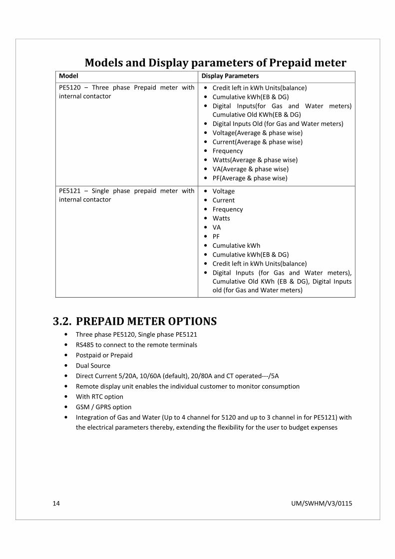
Models and Display parameters of Prepaid meter Model Display Parameters
PE5120 – Three phase Prepaid meter with
internal contactor
• Credit left in kWh Units(balance)
• Cumulative kWh(EB & DG)
• Digital Inputs(for Gas and Water meters)
Cumulative Old KWh(EB & DG)
• Digital Inputs Old (for Gas and Water meters)
• Voltage(Average & phase wise)
• Current(Average & phase wise)
• Frequency
• Watts(Average & phase wise)
• VA(Average & phase wise)
• PF(Average & phase wise)
PE5121 – Single phase prepaid meter with
internal contactor
• Voltage
• Current
• Frequency
• Watts
• VA
• PF
• Cumulative kWh
• Cumulative kWh(EB & DG)
• Credit left in kWh Units(balance)
• Digital Inputs (for Gas and Water meters),
Cumulative Old KWh (EB & DG), Digital Inputs
old (for Gas and Water meters)
3.2. PREPAID METER OPTIONS • Three phase PE5120, Single phase PE5121
• RS485 to connect to the remote terminals
• Postpaid or Prepaid
• Dual Source
• Direct Current 5/20A, 10/60A (default), 20/80A and CT operated---/5A
• Remote display unit enables the individual customer to monitor consumption
• With RTC option
• GSM / GPRS option
• Integration of Gas and Water (Up to 4 channel for 5120 and up to 3 channel in for PE5121) with
the electrical parameters thereby, extending the flexibility for the user to budget expenses

15 UM/SWHM/V3/0115
4. PREPAID METER OPERATION The meter is suitable for Three-phase four wire (PE5120)/ Single Phase 2 wire system (PE5121).
Meter measures electrical energy consumed and decrements the available credit register in accordance
with the energy consumption-KWh or kVAh. The available credit register is incremented as and when
payment is made. Meter continuously calculates the balance credit against the consumption.
As the balance credit decreases beyond the pre-defined level, a switch (latching relay) is used to
disconnect the supply to the load. Meter display starts blinking when the credit balance falls to a
programmed value.
Over voltage (OVER.VOL) Tripping: This is the unique feature from the Elmeasure meter to protect the
equipment when the over voltage occurs. When the Line voltage is more than programmed value the
prepaid meter trips the load, thus protecting the house hold equipments. This replaces the need for
over voltage relays in individual houses.
Over.KVA (EB or DG): Elmeasure meters have the unique feature to program the set limit for
consumption when it is operating on EB and DG in terms of kVA. When the consumption is above the
set value then the LOAD gets disconnected for a span of 1 minute (programmable through
configuration) after which the LOAD gets connected for the SET DELAY time to see the load is reduced
and if the consumption is still higher it trips the load for the 2nd
delay time (programmable) and this
process gets repeated with the different programmable delay time until the consumption is reduced.
DG SELECTION: Elmeasure prepaid meter has great optional feature i.e. individual phases on for DG (R,
Y, B or RYB or No DG). This feature can avoid ACCL to individual houses.
COMMUNICATION SETTINGS:
4.1. KEY FUNCTIONS
Smart Keys Operating the energy meter is easy, using the two smart keys to navigate through the display
pages. The display shows where you are headed.
Protocol Modbus RTU
Data bits 8
Baud rate 9600 Baud, User set 1200 to 19200
Range:1200, 2400, 4800, 9600, 19200
Normal use: 9600 Baud
Noisy, EMI, RFI, long data cable: 4800/2400 Baud
Short cable (< 300 meters or 975 feet): 19200 Baud
Parity Even/odd/no
Device ID 1
Stop bit 1
16 UM/SWHM/V3/0115
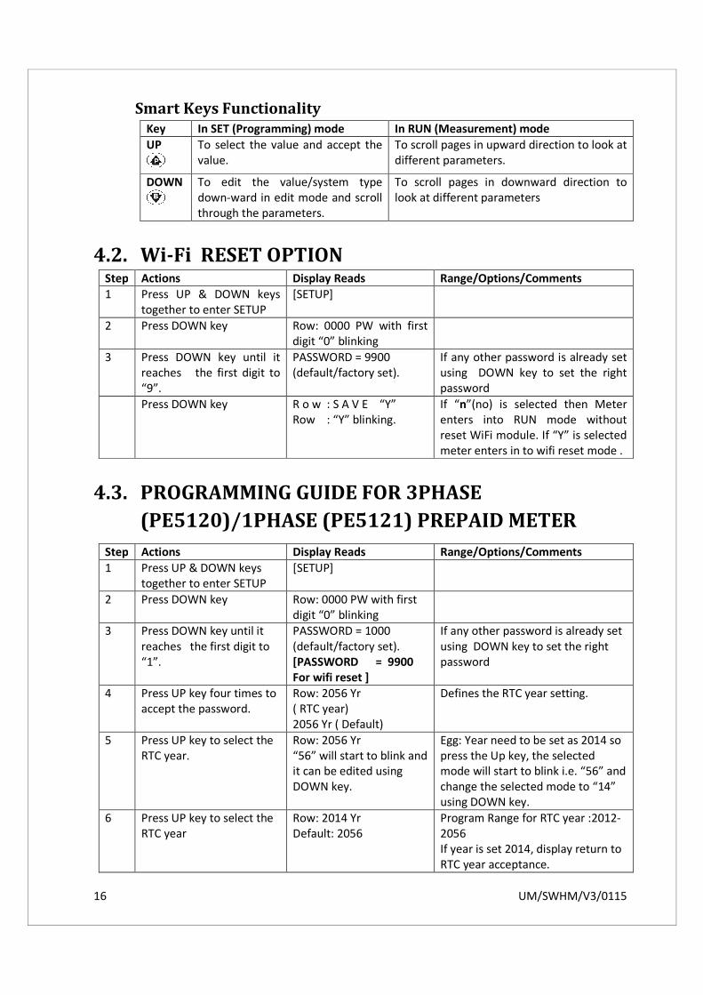
Smart Keys Functionality
Key In SET (Programming) mode In RUN (Measurement) mode
UP
To select the value and accept the
value.
To scroll pages in upward direction to look at
different parameters.
DOWN
To edit the value/system type
down-ward in edit mode and scroll
through the parameters.
To scroll pages in downward direction to
look at different parameters
4.2. Wi-Fi RESET OPTION Step Actions Display Reads Range/Options/Comments
1 Press UP & DOWN keys
together to enter SETUP
[SETUP]
2 Press DOWN key Row: 0000 PW with first
digit “0” blinking
3 Press DOWN key until it
reaches the first digit to
“9”.
PASSWORD = 9900
(default/factory set).
If any other password is already set
using DOWN key to set the right
password
Press DOWN key R o w : S A V E “Y”
Row : “Y” blinking.
If “n”(no) is selected then Meter
enters into RUN mode without
reset WiFi module. If “Y” is selected
meter enters in to wifi reset mode .
4.3. PROGRAMMING GUIDE FOR 3PHASE
(PE5120)/1PHASE (PE5121) PREPAID METER
Step Actions Display Reads Range/Options/Comments
1 Press UP & DOWN keys
together to enter SETUP
[SETUP]
2 Press DOWN key Row: 0000 PW with first
digit “0” blinking
3 Press DOWN key until it
reaches the first digit to
“1”.
PASSWORD = 1000
(default/factory set).
[PASSWORD = 9900
For wifi reset ]
If any other password is already set
using DOWN key to set the right
password
4 Press UP key four times to
accept the password.
Row: 2056 Yr
( RTC year)
2056 Yr ( Default)
Defines the RTC year setting.
5 Press UP key to select the
RTC year.
Row: 2056 Yr
“56” will start to blink and
it can be edited using
DOWN key.
Egg: Year need to be set as 2014 so
press the Up key, the selected
mode will start to blink i.e. “56” and
change the selected mode to “14”
using DOWN key.
6 Press UP key to select the
RTC year
Row: 2014 Yr
Default: 2056
Program Range for RTC year :2012-
2056
If year is set 2014, display return to
RTC year acceptance.

17 UM/SWHM/V3/0115
7 Press DOWN key to go to
the next parameter
Row: 01.01. d Defines the Month & Date of the
clock.
First two digits define the month
selection & another two digits
mention the date.
8 Press the UP key to select
the Month & Date
Row: 01. 01. d (default).
First two digits blinking
which is “month”
selection can be edited
using down key.
Selected mode will blinks and it can
be set to the desired range using
Down key.
Eg: Month need to be set April , set
the selected blink value as “04”
using DOWN key
9 Press UP key to accept the
edited value for month.
Row: 04.01. d
Second digit blinking
which is “Date” selection,
it can be edited using
DOWN key. Press UP key
to accept the edited
value.
10 Press DOWN key to go to
the next parameter
Row: 00.01. t ( Default)
It defines the RTC time settings.
It is in HH:MM format.
11 Press the UP key to select
the Hour & Minute.
Row: 01.01. t
Follow the procedure
steps 8 & 9 for set the
Hour & minute.
12 Press DOWN key to go to
the next parameter
Row: 52.00 Eb (Default in
3phase).
17.50 Eb(Default in single
phase)
Over KVA EB
It defines the over KVA tripping
value for Eb.
Range: up to 9999 Mega
13 Press UP key to select the
over KVA value.
Row: 52.00 Eb.
First digit starts blinking
can be edited using
DOWN key.
(selected mode blinks)
14 Press UP key to accept the
edited value for first digit.
Row: 52.00 Eb
Second digit blinking, can
be edited using DOWN
key. Press UP key to
accept the edited value.
Continue the same
method until fourth digit.
Program range for Over KVA: 52.00
Kilo- 9999.0 Mega.
15 Press UP key Row: 52.00 K Eb.
Decimal point blinking. It
can be set at appropriate
location using DOWN key.
Ascertain the correct
scale (Kilo, Mega) is
selected. Press UP key to
accept the edited value.
Egg. To set 11.00 K.
Set first four digits (1100) as
explained above. Press DOWN key
to place decimal point at
appropriate location with
respective LED (kilo, Mega)
indication.

18 UM/SWHM/V3/0115
16 Press DOWN key to go to
the next parameter
Row: ryb dG. (Default)
Phase selection in DG
(only in 3 phase meter)
It defines which phase needs to be
work in DG.
Ranges: ryb,r,y,b
17 Press UP key to select the
edited value.
Row: ryb dG.
Selected mode blinks and
select any of the phase
selection as mentioned in
the range using DOWN
key. Press UP key to
accept the selected mode.
18 Press DOWN key to go to
the next parameter
Row : display 285.0 O.V
(over voltage)
285.0 O.V (Default)
Defines the over voltage settings
between Line to neutral.
Range: 80-310 V
19 Press UP key to select the
over voltage value
Row: 285.0 O.V (Over
Voltage)
First digit blinking can be
edited using DOWN key.
(selected mode blinks)
20 Press UP key to accept the
edited value for first digit.
Row : 285.0 O.V
Second digit blinking, can
be edited using DOWN
key. Press UP key to
accept the edited value.
Continue the same
method until fourth digit.
Program Range for Over Voltage :
80V to 310V
If value set is above this limit,
display returns to the maximum O.V
value acceptable.
21 Press DOWN key to go to
the next parameter
Row: 5.000 d.t (Delay
Time). Follow the
procedure as described in
steps 5 & 6
5.000 (default)
It defines the delay time for relay
tripping
Range: 1-180 sec
22 Press DOWN key Row : 9600.b (Baud rate)
Communication Speed
(9600-Default / factory
set)
Defines the Baud rate Option:
2400, 4800, 9600, 19.2k.
23 Press DOWN key Row : EVEn P (Parity)
Even/ Odd/ None
Even(even)/ Odd( odd)/ No( No
parity)
(Internal Communication error
Check)
24 Press DOWN key Row : 1.000 Id( Device ID)
1.000 (Default)
Defines the ID.
Communication identification
Number. Option :1- 247
25 Press DOWN key Row: ------ (Password).
User Programmable
password, range 1000 to
9999.
If the password is forgotten the
meter will be reset and calibrated
at factory only.
20 Press DOWN key Row : rESO E.S (Energy
Selection) rESO (Default)
Option: resolution/counter
(rESO/COUN).Energy value format
i.e., the energy accumulated in the
meter to be displayed in resolution
or counter format

19 UM/SWHM/V3/0115
21 Press DOWN key Row : 5.000 A.t. ( Auto
scroll time)5.000 (
Default)
Range: 1 to 10 seconds
Display increment during auto
scroll.
22 Press DOWN key R o w : S A V E
Row 2: “Y” blinking.
If “n”(no) is selected then Meter
enters into RUN mode without
memorizing any edited Values in
the setup
The List of parameters that can be configured and the range is given below
Sl. No. Parameter Default setup Range
1 Over Voltage(L-N) [ O.V ] 285.0 80V-310V
2 Over KVA 52.00 52-999K
3 Individual phases change on DG RYB R (or) Y (or) B (or) RYB
(or) No DG
4 Delay Time [d.t] 5.000 1-180s
5 Baud rate [b] 9600 2400 to 19.2k
6 Parity(P) EVEn Even/ Odd/ no
7 Device Id (I d) 1.000 1.000 to 247.0
8 Password 1000 1000 to 9999
9 Energy selection mode [E.S] rESO rESO /COUΠ
10 Display increment time during auto scroll [A.t] 5.000 1 to 10 seconds
Enabling and Disabling of Auto scrolling: Enabling Auto Scrolling: Press DOWN key continuously for 5 seconds or until display shows EnAb.Au
for downward scrolling. The auto scrolling will be enabled automatically when the meter is OFF and
ON.
Disabling Auto Scrolling: Press UP/DOWN key to disable auto scrolling. Display shows dlSA.Au and
returns to normal mode.
4.4. PREPAID OPTIONS
RF based • Secured Encrypted RF Smart Card based recharging
• Elmeasure encryption also added for improving the security
• Can have multiple card- one with low value charged for emergency
• Over KVA tripping when the meter is running in DG (programmable through the smart card)
• Reconnection time is programmable-10sec, 1 min, 10 min, 2 hrs. monthly fixed charges based
on KVA/KW
• RTC option available: Holiday and night time cutoff prevention, Grace amount can be set from
factory, Option of programming for non tripping during week end

20 UM/SWHM/V3/0115
GSM/GPRS based • Recharging with the secure authentication code and secure reply
• Meter with Real Time Clock (RTC option)
• Sends power outage & power resumption timings with date & time stamp after the power
resumes to the server
• Response for all the successful, failure recharge with the reasons
• Force ON and OFF the load through SMS (Resets with the power cycle)
• Remote configuration of unit cost (cost per KWh) and the slab wise cost
• Remote Configuration of change in Threshold, Negative balance, Tariff in the secure mode
• Initiate the SMS when balance reaches the 20% or 15% of the threshold value
• Information like profiling, recharge history can be available through smart mobile applications
• Avoids Remote display
WI-FI based • Recharging with the secure authentication code and secure reply
• Meter with Real Time Clock (RTC option)
• Sends power outage & power resumption timings with date & time stamp after the power
resumes to the server
• Response for all the successful, failure recharge with the reasons

21 UM/SWHM/V3/0115
• Remote configuration of unit cost (cost per KWh) and the slab wise cost
• Remote Configuration of change in Threshold, Negative balance, Tariff in the secure mode
• Initiate the message when balance reaches the 20% or 15% of the threshold value
• Information like profiling, recharge history can be available through smart mobile applications
• Avoids Remote display
RS485 with Aggregator • Cost effective solution
• Aggregator collects information and transfer data through Ethernet/Wifi/USB/GPRS to the
server
• ELNet billing software for profiling
Aggregator-AG 1000
Aggregator AG1000 is a web based high end data concentrator and All-In-One multi protocol
communication interfacing unit that supports the Modbus protocol and has different types of
communication channels. Introduction of the Aggregator allows for flexibility to cater to wired
or wireless environments with built in storage, providing the end user with a robust solution of
Energy Management. One of the major advantages of AG1000 is the data storage capacity of
upto 64GB which can be transferred to a remote server at pre-defined time intervals that
allows for built in data redundancy. Data for 64 devices recording 62 parameters each at 1 min
intervals can be stored for up to 5 years. The same data can be directly viewed and can also can
22 UM/SWHM/V3/0115
be pushed to the cloud with the built in web server software, enabling the user to collect and
monitor the system without the system without geographical boundaries. Communication
channels of RS485, Ethernet, Wi-Fi, Zigbee and GPRS (2G & 3G) are available in the unit.
Key Features:
• Rugged construction meet harsh industrial environments
• Data reliability improved through redundancy
• Isolated communication channels for better safety and reliable operation
• Data can be pushed to the cloud server for integration with customer end applications
• Flexible installation can be configured to match the customer requirements
• Remotely monitoring- generate alarms in case of any error
• Signal strength notification for easy installation and maintenance
• Compact construction –Din rail and wall mountable
Communication channels available in AG1000:
• RS485 with Isolated wired
• Ethernet wired
• Wi-Fi wireless
• Bluetooth Wireless
• Zigbee Wireless
• GPRS (2G & 3G) wireless
4.5. PREPAID FUNCTIONS • Advanced collection of revenue before electrical power consumption.
• Charging the meter with credit revenue through multiple options (Smart card or Wired or
GSM/GPRS).
• The loaded revenue decrements based on the rate of electricity at that time (Currency/unit),
which may change from time to time.
• Provides visible and audible alarm to the user when the credit balance falls to a particular value
at the meter as well as at the remote display unit (Optional).
• Secured transactions, bill and report generation.
• The implementation of prepayment accounting functions can be separated into credit and
charge functions. The credit functions include:
1. Token credit function
2. Emergency credit function
Two types of charge functions are implemented:
1. Consumption-based tariff charges
2. Time-based auxiliary charges

23 UM/SWHM/V3/0115
Token credit function:
Token Credit function deals with managing credit registers according to credit token transfer.
When credit transfer is accepted, the values of “Available Credit Register” and “Total Purchase
Register” are increased for the amount credit transferred.
Emergency credit function:
Emergency credit function is used in situations when “Available Credit Register Value” approaches
or goes under zero. For this purpose, three parameter objects are implemented:
1. Emergency Credit Initial Limit
2. Emergency Credit Limit
3. Emergency Credit Threshold
“Emergency Credit Initial Limit” is used once after meter installation for the purpose of enabling
the customer to make the first buy (or transferring the first credit from the management centre).
It defines the credit value which is available when emergency credit is first selected by the
customer.
“Emergency Credit Limit” defines the credit value which is available after the value of “Available
Credit Register” reaches zero and the customer selects the emergency credit.
“Emergency Credit Threshold” defines the positive value of “Available Credit Register” at which
the meter begins to notify the customer that the credit will expire. When the value of “Available
Credit Register” falls below the value of “Emergency Credit Threshold”, the meter starts
notification.
5. FEATURES OF PREPAID METER
5.1. COMMON FEATURES • User friendly, compact wall mounting design
• Dual source measurements up to 80A whole current/CT operated
• Currency based recharging for EB, DG, Gas and Water (Up to 4), pricing can be programmed
independently
• No separate EB and DG recharging
• Displays and communicates balance, VLL, VLN, A, F, W, PF, VA, KWh EB and DG, Gas and Water
input pulse
• Tripping of EB or DG consumption at pre-determined set point for protection and effective use
of energy
• Current Limiting facility for DG/EB separately
• History of recharge
• Protect your equipment against overload/over voltage/harmonics

24 UM/SWHM/V3/0115
• Selection of DG powers either 3phase or single phase programmable at site- replaces ACCL &
minimize wiring complexity
• Over voltage protection at 285v default (programmable at site)
• Display blinks in the frequent interval to indicate low balance
• EB to DG to EB changeover through 240V AMF / RS485 communication
• For DG phase wise (R or Y or b or RYB or No DG)
• EB over consumption limit
• Programmable Time delay
• 4DI (except RF) / 2DI
• Programmable alarm value to blink the display
5.2. OPTIONAL FEATURES • Optional RTC
• Monthly (on programmable day)/Weekly (on day of the week) /Daily (on time) deduction
programmable
• 14 programmable holidays
• 2 programmable Weekend holidays (can be programmed to any 2 days or 1day)
• Happy Hours (can be programmed to any time of the day)
• Service provider can Force off and on the load
• Emergency credit to take of residence / occupants even with zero balance
• Programmable 4 slab based on the tariff
• Programmable 2 TOD based on the time (slab programmable independently)
6. TECHNICAL SPECIFICATIONS The following table gives the Technical Specifications of the prepaid single phase meters PE5121 /
Three phase energy meter PE5120.
Parameter Range
Connection Single Phase,2 wire, PE5121 / Three phase, 4wire,
PE5120
Accuracy Class 1 (Default) IEC 61036, CBIP 88
Sensing / Measurement True RMS, 1 Sec update time, 2 Quadrant Power &
Energy
Voltage
Burden
External Fuse Rating
80- 240V Phase to Neutral
5VA Max.
60A
Current Basic Current Ib = 10A
Maximum Current Imax = 60A

25 UM/SWHM/V3/0115
Frequency 50Hz ± 5 %
Pulse Constant 1000 pulses/Kwh
Display Resolution 1 Rows, 6 digits (10mm height)
Operating Temperature -10o
C to +55o
C (14o
F - 131o
F)
Storage Temperature -25o C to +70o C (-13o F - 158o F)
Humidity 5% to 95% non condensing
Communication RS 485 serial channel connection Industry standard
Modbus RTU protocol
Baud rate 2400 bps to 19200 bps (preferred 9600 bps)
Isolation 2000 volts AC isolation for 1 minute between
communication and other circuits
Gas/Water input option Factory configurable Digital input with Maximum
Frequency 3Hz for up to 4 channel or Analog Input
4-20mA or 0-20mA for 2 channel programmable at
field or 1-10DC voltage
Weight (appox.) unpacked 670 gms for PE5121 / 1650 for PE5120
Shipping(packed) 750 gms for PE5121 / 1750 for PE5120
Dimensions(mm) 160 × 112 mm (Depth 58mm behind bezel)
The following table gives the Technical Specifications of the Prepaid Three phase meters (PE5120) CT
operated meter.
Parameter Range
Connection 3 Phase,4 wire, PE5120 CT operated
Accuracy Class 1 (Default) IEC 61036, CBIP 88
Sensing / Measurement True RMS, 1 Sec update time, 2 Quadrant Power & Energy
Input voltage (Measurement) 4 voltage inputs(VR,VY,VB,VN)
Programmable 110 or 415VLL Nominal(Range 80 to 550VLL),
Primary Programmable up to 999kV
Burden
External Fuse Rating
0.2VA Max. per phase
2A
Input Current(Measurement)
Current Inputs (AR,AY,AB) 50mA-6A(Field programmable 1A or
5A) , Primary Programmable up to 99kA for CT operated one.
Overload
Burden
10VA Max. Continuous, 50A max. for 3 sec.
0.5VA Max. per phase
CT PT Ratio Max 2000MVA programmable
Display Resolution 1 Rows, 6 digits (10mm height)

26 UM/SWHM/V3/0115
Humidity 5% to 95% non condensing
Operating Temperature -10o
C to +55o
C (14o
F - 131o
F)
Storage Temperature -25o C to +70o C (-13o F - 158o F)
Communication RS 485 serial channel connection, Industry standard. Modbus
RTU protocol.
Baud rate 2400 bps to 19200 bps (preferred 9600 bps)
Isolation 2000 volts AC isolation for 1 minute between communication
and other circuits
Gas/Water input option Factory configurable Digital input with Maximum Frequency
3Hz for up to 4 channel or Analog Input 4-20mA or 0-20mA for
2 channel programmable at field or 1-10DC voltage
Weight 3 phase: Unpacked-1650 gms, Packed 1850gms
Dimension Bezel 173 × 262 mm (Depth 82mm behind bezel)
7. COMMUNICATION
7.1. COMMUNICATION OPTIONS
7.1.1. RS485 The RS-485 bus standard is one of the most widely used physical layer bus designs in
industrial applications. The key features of RS-485 that make it ideal for use in industrial
communications and the applications are
• Bi directional communication in the single pair of twisted cables
• Multiple Driver can be connected to the same bus
• Differential communication makes it work for long distance upto 3000 feets or
approximately 900 meters (depending on the cable and environment)
7.1.2. SMARTCARD A smart card, chip card, or integrated circuit card (ICC) is any pocket-sized card with
embedded integrated circuits.
The benefits of smart cards are directly related to the volume of information and applications
that are programmed for use on a card. A single contact/contactless smart card can be
programmed with multiple banking credentials, medical entitlement, driver’s license/public
transport entitlement, loyalty programs and club memberships to name just a few. Multi-
factor and proximity authentication can and has been embedded into smart cards to increase
the security of all services on the card.
27 UM/SWHM/V3/0115
Commercial Applications:
The smart card’s portability and ability to be updated make it a technology well suited for
connecting the virtual and physical worlds, as well as multi-partner card programs.
• Banking/payment
• Loyalty and promotions
• Access control
• Stored value
• Identification
• Ticketing
• Parking and toll collection
7.1.3. GSM/GPRS GSM (Global System for Mobile communications) is an open, digital cellular technology used
for transmitting mobile voice and data services. GSM supports voice calls and data transfer
speeds of up to 9.6 kbps, together with the transmission of SMS (Short Message Service).
GPRS stands for General Packet Radio Service and is a second generation (2G) and third
generation (3G)--or sometimes referred to as in-between both generations, 2.5G--wireless
data service that extends GSM data capabilities for Internet access, multimedia messaging
services, and early mobile Internet applications via the wireless application protocol (WAP),
as well as other wireless data services.
GPRS was one of the earliest cell phone data access technologies
GPRS is the most widely supported packet-data wireless technology in the world. Like GSM,
GPRS supports international roaming so customers can access data services whether they are
at home or abroad. When users travel to areas that have not yet been upgraded to GPRS,
they still can access many data services via circuit-switched GSM.
Features and benefits of GSM/GPRS Modem
• Designed for use at energy meter
• The modem takes readings at scheduled intervals
• Stored data is transfer in fast mode on request from central station
• SMS to predefined mobile numbers for anomalous events of meter
• Flexibility to enable reading of any type of electronic meters (pre-configured)
• Suitable for HT and LT metering installations
• Modem with built-in wide range power supply
• Sealing provision
• Suitable for wall mounting
• Connection types
o Single meter
o Multiple meters (Secure make) via optional multiplexer interface
• Meter connectivity through
o Optical communication port
o Serial RS232 communication port
o Serial RS485 communication port (for Secure make meters)

28 UM/SWHM/V3/0115
• IP 51 compliant
• Multiple LEDs for Status indication
• SIM card holder (sliding with sealing provision)
GSM/GPRS Specification:
• Works with global Quad band. Can be used with any GSM operators
• GPRS class B mobile station
• Compliant with GSM phase 2/2- class 4 (2W @850/900 MHZ, class1
(1W@1800/1900MHZ))
7.1.4. WI-FI Wi-Fi is a local area wireless technology that allows an electronic device to exchange data or
connect to the internet using 2.4 GHz UHF and 5 GHz SHF radio waves. These can connect to
a network resource such as the Internet via a wireless network access point. Such an access
point (or hotspot) has a range of about 20 meters (66 feet) indoors and a greater range
outdoors. Hotspot coverage can comprise an area as small as a single room with walls that
block radio waves, or as large as many square kilometers achieved by using multiple
overlapping access points.
Features and benefits of WI-FI
• Enable staff to carry portable Wi-Fi handsets giving them the ability to work
anywhere, anytime.
• Using Wi-Fi enables PDA’s and Laptops to deliver quick and easy access to information
• Eliminate cellular usage charge.
• Eliminate cabling and wiring for PC’s
• Eliminate switches, adapters, plugs, pins, and connectors.
• Secure networking using the latest secure networking protocols
• Simplified management software.
• Radio Frequency sweeping technology that disables rogue and ad hoc wireless devices
not relevant to the network
• Fast roaming and seamless data packet transfer
• Quality of Service or QO
7.1.5. REMOTE UNIT A Remote Unit (RU) is a microprocessor-controlled electronic device that interfaces objects
in the physical world to a distributed control system by transmitting telemetry data to a
master system, and by using messages from the master supervisory system to control
connected objects.

29 UM/SWHM/V3/0115
Features:
• Elegant design
• Displays all parameters including balance
• No separate power is required
• 100 meter distance from the meter using CAT 5 cable
• Display blinks and buzzer on in the frequent interval to individual
• When idle state remote unit shows balance only
• Manual SET button for re-connection
Applications:
Remote monitoring of functions and instrumentation for:
• Oil and gas (offshore platforms, onshore oil wells)
• Networks of pump stations (wastewater collection, or for water supply)
• Environmental monitoring systems (pollution, air quality, emissions monitoring)
• Mine sites
• Air traffic equipment such as navigation aids (DVOR, DME, ILS and GP)
Remote monitoring and control of functions and instrumentation for:
• Hydro-graphic (water supply, reservoirs, sewerage systems)
• Electrical power transmission networks and associated equipment
• Natural gas networks and associated equipment
• Outdoor warning sirens
7.2. COMMUNICATION REGISTER MAP FOR PREPAID
METER All the parameters declared in the communication map are float and follows the standard
Modbus RTU protocol. The data can be retrieved individually or together as a block.
Sl. No. Parameter Data type Address
1 Watts Total float 40101
2 Watts R phase float 40103
3 Watts Y phase float 40105
4 Watts B phase float 40107
5 Reserved, communicates zero float 40109
6 Reserved, communicates zero float 40111
7 Reserved, communicates zero float 40113
8 Reserved, communicates zero float 40115
9 PF Ave. (Instantaneous) float 40117
10 PF R phase float 40119
11 PF Y phase float 40121
12 PF B phase float 40123

30 UM/SWHM/V3/0115
13 VA total float 40125
14 VA R phase float 40127
15 VA Y phase float 40129
16 VA B phase float 40131
17 VLL average float 40133
18 Vry phase float 40135
19 Vyb phase float 40137
20 Vbr phase float 40139
21 VLN average float 40141
22 V R phase float 40143
23 V Y phase float 40145
24 V B phase float 40147
25 Current Total float 40149
26 Current R phase float 40151
27 Current Y phase float 40153
28 Current B phase float 40155
29 Frequency float 40157
30 Wh EB (if meters is manufactured for Wh), VAh
EB(if the meter is manufactured for VAh) float 40159
31 Reserved, communicates zero float 40161
32 Reserved, communicates zero float 40161
33 Reserved, communicates zero float 40161
34 Wh DG (if meters is manufactured for Wh), VAh
DG(if the meter is manufactured for VAh) float 40167
8. TROUBLESHOOTING
CAUTION
During reparation and maintenance, do not touch the meter connecting clamps directly with your
bare hands, with metal, blank wire or other material as you will have the chance of an electricity
shock and a possible chance for health damage.
Turn off and lock out all power supplying the energy meter and the equipment to which it is installed
before opening the protection cover to prevent the hazard of an electric shock.
WARNING
Maintenance or reparations should be performed by qualified personnel familiar with applicable
codes and regulations.
Use insulated tools to maintain or repair the meter.
Make sure the protection cover is in place after maintenance or repair

31 UM/SWHM/V3/0115
Due to programming error, site conditions, some problems can cause the Meter malfunction. The
fault symptoms and their remedial action for correction is given below.
If the display does not turn ON
• Check that there is at least 110 V available in power supply
• Check the link connected or not
Recharging not happening through RS 485
• Check the connectivity for RS485
• Check the meter ID correct or not
• Check the Elnet PPS selection correct or not
Recharging not happening through RF card.
• Check the RF card serial no and meter serial no is correct or not
• Check proper PPS select or not
• Check the RF card recharge properly
Display blinking
• Balance is below the limit
• Load off condition
• Check the balance is zero
• Check the over voltage occur
• Check the over KVA occur
If RS-485 communication does not work:
• Check that the baud rate of the host computer/PLC is the same as Meter
• Check that the device ID of the meter is unique and should not replicate
• Check all communications wiring is complete
• Check that the number of data bits is set to 8, with one stop bit and even parity
9. DISCLAIMER Sufficient care is taken to provide all information regarding the product but ElMeasure does not
responsible the product which has been damaged due to improper installation, improper handling,
improper connections, neglect, misuse, accident, and abnormal conditions of operation and natural
calamities or acts of god.