Embed Size (px)
Citation preview
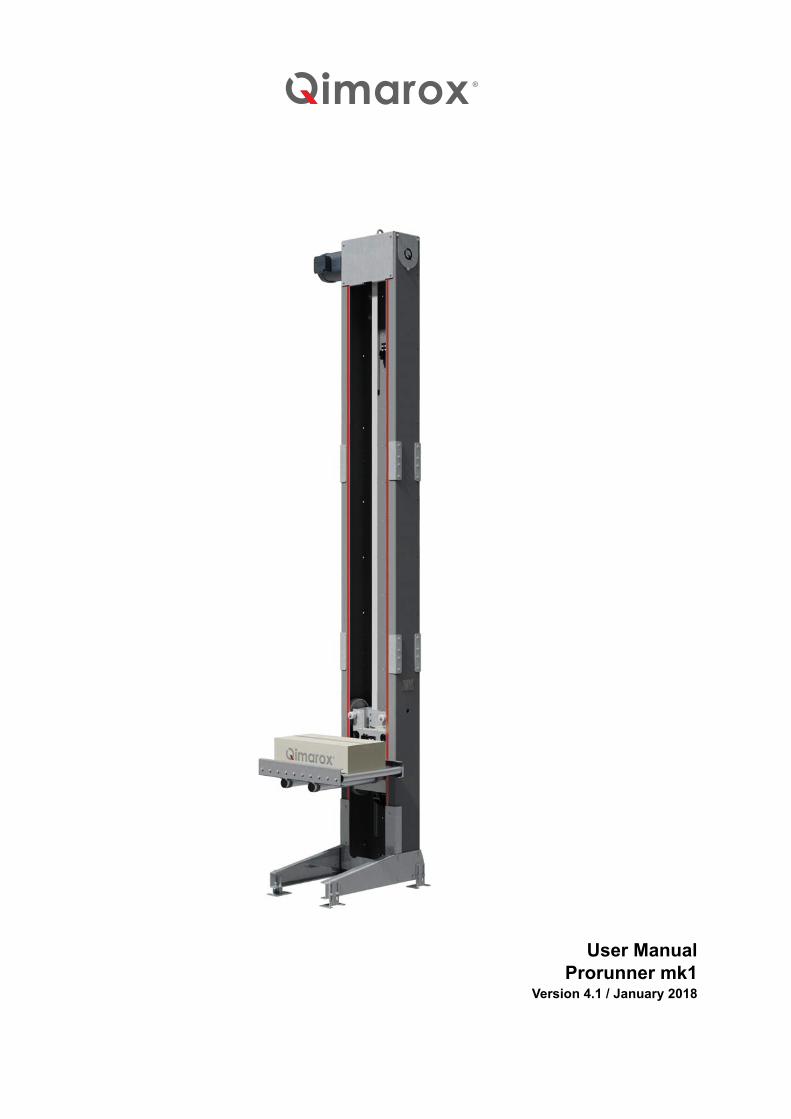
User ManualProrunner mk1
Version 4.1 / January 2018
2 UM-Prorunner_mk1-4.1-EN
/i
QimaroxNobelstraat 43 3846 CE Harderwijk The Netherlands
Tel: +31 341 436 700 Fax: +31 341 436 701 E-mail: [email protected] Internet: www.Qimarox.com
Copyright © Qimarox B.V. All rights reserved. No part of this publication may be reproduced, stored in a computer database or published in any form or in any way electronically, mechanically, by means of photocopying, recordings or in any manner without prior written permission from Qimarox.
UM-Prorunner_mk1-4.1-EN 3
Table of contents1 About this manual
1.1 Introduction............................................................................................................................. 51.2 Product documentation .......................................................................................................... 51.3 Source language .................................................................................................................... 51.4 Symbols used in the manual .................................................................................................. 61.5 Terminology list ...................................................................................................................... 61.6 Further support and information ............................................................................................. 7
2 General2.1 Machine identification............................................................................................................. 82.2 Machine layout drawing and specifications ............................................................................ 82.3 Warranty ................................................................................................................................. 92.4 Liability ................................................................................................................................... 92.5 CE Declaration of Conformity ............................................................................................... 10
3 Safety3.1 Intended use of the machine ................................................................................................ 113.2 User types and qualifications ............................................................................................... 113.3 Safety instructions ................................................................................................................ 113.4 Safety provisions .................................................................................................................. 123.5 Potential risks ....................................................................................................................... 143.6 Machine end of life and environment disposal ..................................................................... 14
4 Description4.1 General overview ................................................................................................................. 154.2 Working principle .................................................................................................................. 164.3 Sensors ................................................................................................................................ 164.4 Motor .................................................................................................................................... 194.5 Control .................................................................................................................................. 204.6 Machine in a system............................................................................................................. 214.7 Specifications ....................................................................................................................... 23
5 Installation5.1 Delivery ................................................................................................................................ 245.2 Unpacking ............................................................................................................................ 245.3 Location................................................................................................................................ 255.4 On-site transport................................................................................................................... 255.5 Preparations for a Qimarox installation (optional) ................................................................ 265.6 Installing the machine........................................................................................................... 27
6 Maintenance6.1 Specific safety regulations.................................................................................................... 326.2 Preventive maintenance schedule, machine excluding the transporter ............................... 33
4 UM-Prorunner_mk1-4.1-EN
6.3 Cleaning ............................................................................................................................... 356.4 Replace parts ....................................................................................................................... 36
7 Troubleshooting7.1 Vertical conveyor .................................................................................................................. 44
8 CE declaration of conformity9 Exploded views
9.1 Frame parts .......................................................................................................................... 479.2 Carrier................................................................................................................................... 549.3 Assembly .............................................................................................................................. 569.4 Labels ................................................................................................................................... 58
10 Electrical drawings10.1 Standard electric drawings ................................................................................................... 6010.2 Drives ................................................................................................................................... 61

UM-Prorunner_mk1-4.1-EN 5
About this manual
1 About this manual1.1 Introduction
This manual provides information about the Prorunner mk1, which is used for the vertical movement of products within a transport system. From here in the manual, the Prorunner mk1 will be referred to as the “machine”.
This manual is intended for:
• Retailers/Original Equipment Manufacturers (OEM) project engineers and mechanics.• Operator, installation and maintenance engineers and other users.
It is important to carefully read this manual as soon as possible after purchase of the machine.
Before you operate the machine, this manual should be read by all users. This is necessary to make sure that all new users are familiar with the content of this manual.
System integrators/OEMsThis manual explains machine configurations you can use to set up the machine. It also provides instructions on how to add or change the machine technical components.
UsersThe machine may be supplied fully assembled. If so, some chapters in this manual will not be applicable. To integrate the machine within a transport system, Qimarox advises you to refer to documentation provided by the OEM of the transport system.
1.2 Product documentation/i
1.3 Source languageThis manual was originally written in the English language.
Document Reference
Machine manual1
1 Generic information for each machine, apart from exceptions outlined in the machine lay-out drawing.
UM-Prorunner_mk1-4.1-EN
Machine assembly instructions1 AI-Prorunner_mk1-1.4-EN
Electrical components Refer to the manufacturer
Electrical drawings1 Refer to chapter 10
Specification sheet2
2 Machine specific information.
Refer to section 2.2
About this manual
6 UM-Prorunner_mk1-4.1-EN
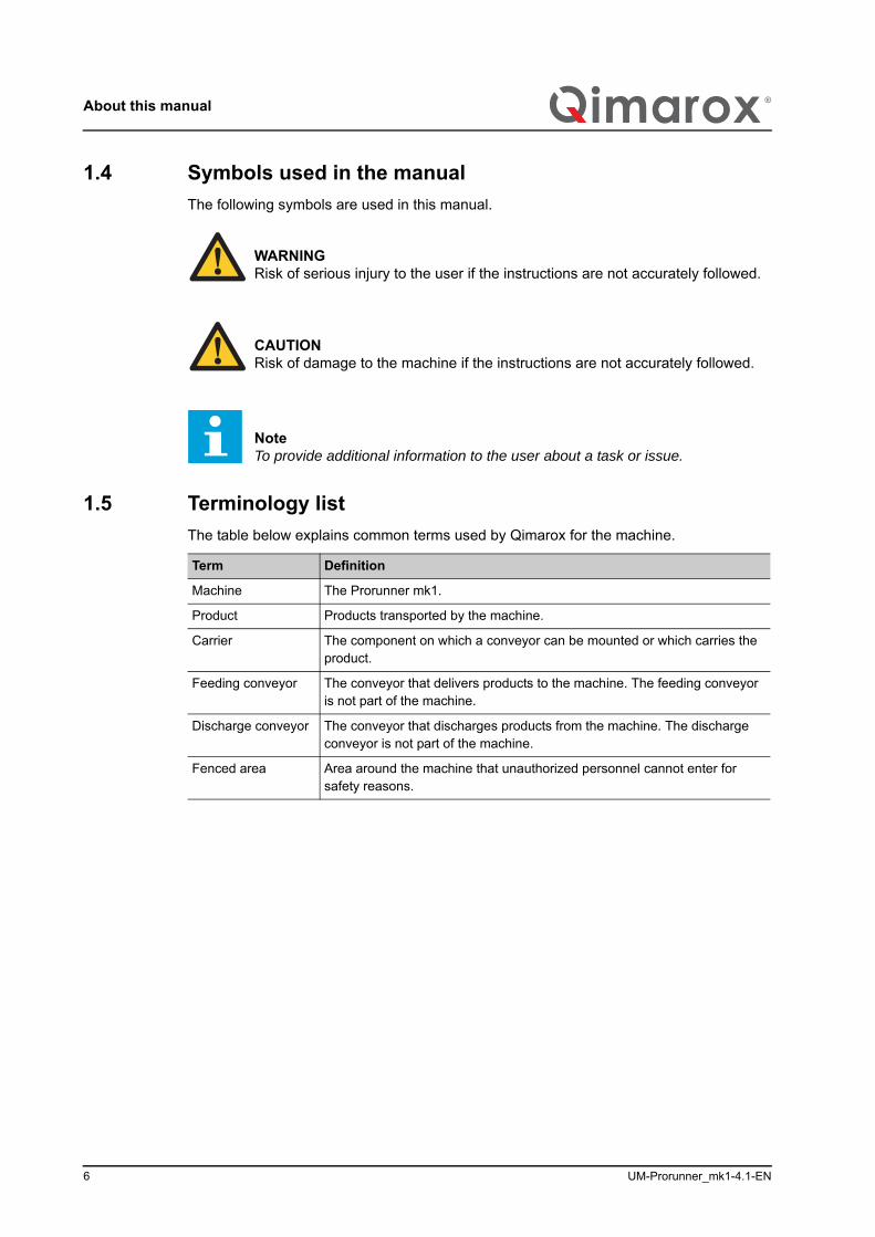
1.4 Symbols used in the manualThe following symbols are used in this manual.
1.5 Terminology listThe table below explains common terms used by Qimarox for the machine.
WARNINGRisk of serious injury to the user if the instructions are not accurately followed.
CAUTIONRisk of damage to the machine if the instructions are not accurately followed.
NoteTo provide additional information to the user about a task or issue.
Term Definition
Machine The Prorunner mk1.
Product Products transported by the machine.
Carrier The component on which a conveyor can be mounted or which carries the product.
Feeding conveyor The conveyor that delivers products to the machine. The feeding conveyor is not part of the machine.
Discharge conveyor The conveyor that discharges products from the machine. The discharge conveyor is not part of the machine.
Fenced area Area around the machine that unauthorized personnel cannot enter for safety reasons.

UM-Prorunner_mk1-4.1-EN 7
About this manual
1.6 Further support and information
Qimarox can supply additional expertise and support services, for:
• Training• Global support• Service contracts
For more information please contact Qimarox.
General
8 UM-Prorunner_mk1-4.1-EN
2 General2.1 Machine identification
The machine identification is given on the type plate. The type plate is located on the side of the machine.
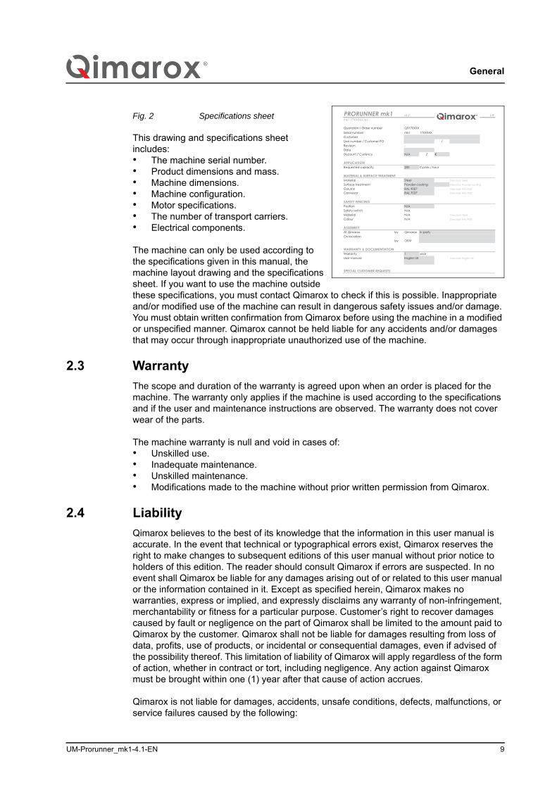
2.2 Machine layout drawing and specificationsAfter a machine order is placed, you will receive a machine drawing and specifications sheet for approval. After your approval this sheet is used as a reference for this manual.
Fig. 1 Machine drawing
PRORUNNER mk
PRORUNNER mk1(kg)
PRORUNNER mk
mk
PRORUNNER mk
NoteThe machine layout drawing illus-trated shows an example.
Fro
A A
nt view
Side view
Top view
Footprint
Bottom section
ProductsMax. contour
Scale 1:25
Surface roughness (Ra): Unless indicated otherwise
Roughness indications according to EN-ISO-1302 / NPR 3634Weld symbols according to NEN-EN-ISO 2553Tolerancing of form and location according to NEN-EN-ISO 1101
Scale:
Sheet size: 1 / 1
Third angle
Date:20-3-2017Drawn:
Appr:
Author:VvE
Item:
Layout PRORUNNER mk1 17XXXXX
Tolerancesunless indicatedotherwise.
Angle: ±1°
0 - 20 - 200 - 2000Machining
±0.2 - ±0.5 - ±1.0Sheet and weld constructions
±0.5 - ±1.0 - ±2.0
Size fillet weldunless indicatedotherwise.
2 - 3 - 4 - 5 - 6| | | | |
1 - 2 - 4 - 6 - 8 - 10Sheet thickness [mm]
a =
Weight:
imar
ox
Revision: Document:
Projectnumber: Customer:QS17XXXX [customer] - [reference]
482,6 kg
1 : 50
AE0022426 A AE0024011.dwg
A3 Sheet number:
ADoc. rev:
For ReviewLayout PRORUNNER mk1 17XXXXX
140
580
930
94
67- 2
050+
7037
600
3321
6010
Tra
vel
6610
32�
Rem
ain
ing
trave
l
75
436
245
825
Plug-in terminal
760
250
Keep
cle
ar f o
r m
aint
ena
nce
0�
Rem
ain
i ng
trave
l
610600
300
UM-Prorunner_mk1-4.1-EN 9
General
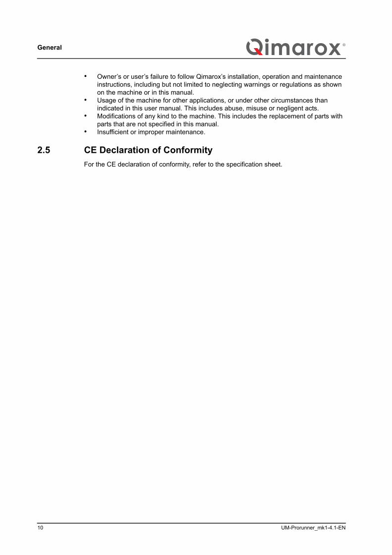
Fig. 2 Specifications sheet
This drawing and specifications sheet includes:• The machine serial number.• Product dimensions and mass.• Machine dimensions.• Machine configuration.• Motor specifications.• The number of transport carriers.• Electrical components.
The machine can only be used according to the specifications given in this manual, the machine layout drawing and the specifications sheet. If you want to use the machine outside these specifications, you must contact Qimarox to check if this is possible. Inappropriate and/or modified use of the machine can result in dangerous safety issues and/or damage. You must obtain written confirmation from Qimarox before using the machine in a modified or unspecified manner. Qimarox cannot be held liable for any accidents and/or damages that may occur through inappropriate unauthorized use of the machine.
2.3 WarrantyThe scope and duration of the warranty is agreed upon when an order is placed for the machine. The warranty only applies if the machine is used according to the specifications and if the user and maintenance instructions are observed. The warranty does not cover wear of the parts.
The machine warranty is null and void in cases of:• Unskilled use.• Inadequate maintenance.• Unskilled maintenance.• Modifications made to the machine without prior written permission from Qimarox.
2.4 LiabilityQimarox believes to the best of its knowledge that the information in this user manual is accurate. In the event that technical or typographical errors exist, Qimarox reserves the right to make changes to subsequent editions of this user manual without prior notice to holders of this edition. The reader should consult Qimarox if errors are suspected. In no event shall Qimarox be liable for any damages arising out of or related to this user manual or the information contained in it. Except as specified herein, Qimarox makes no warranties, express or implied, and expressly disclaims any warranty of non-infringement, merchantability or fitness for a particular purpose. Customer’s right to recover damages caused by fault or negligence on the part of Qimarox shall be limited to the amount paid to Qimarox by the customer. Qimarox shall not be liable for damages resulting from loss of data, profits, use of products, or incidental or consequential damages, even if advised of the possibility thereof. This limitation of liability of Qimarox will apply regardless of the form of action, whether in contract or tort, including negligence. Any action against Qimarox must be brought within one (1) year after that cause of action accrues.
Qimarox is not liable for damages, accidents, unsafe conditions, defects, malfunctions, or service failures caused by the following:
v3.2 1/8
mk1
/-
N/A / €
Requested capacity 200 Cycles / hour
by Qimarox
by OEM
1 yearStandard: English UK
Customer
Warranty
At Qimarox In parts
WARRANTY & DOCUMENTATION
ASSEMBLY
On location
SPECIAL CUSTOMER REQUESTS
PRORUNNER mk1
Quotation / Order numberSerial number 17XXXXX
mk1 17XXXXX rev -
User manual
MATERIAL & SURFACE TREATMENT
Column
Standard: Steel
Conveyor
Discount / Currency
QS170XXX
Line number / Customer PO
MaterialPowder coating
N/A
Standard: Powder coating
Date
APPLICATION
Revision
Surface treatmentStandard: RAL 9007
English UK
Colour Standard: RAL 9005
Standard: SteelMaterial N/AN/ASafety switchN/A
Standard: RAL 7037
Steel
RAL 9007RAL 7037
SAFETY FENCINGPosition
General
10 UM-Prorunner_mk1-4.1-EN
• Owner’s or user’s failure to follow Qimarox’s installation, operation and maintenance instructions, including but not limited to neglecting warnings or regulations as shown on the machine or in this manual.
• Usage of the machine for other applications, or under other circumstances than indicated in this user manual. This includes abuse, misuse or negligent acts.
• Modifications of any kind to the machine. This includes the replacement of parts with parts that are not specified in this manual.
• Insufficient or improper maintenance.
2.5 CE Declaration of ConformityFor the CE declaration of conformity, refer to the specification sheet.

UM-Prorunner_mk1-4.1-EN 11
Safety
3 Safety3.1 Intended use of the machine
The machine is exclusively intended for the vertical transportation of products, as described in this manual. Refer to chapter 4 for a detailed description of the specifications of use.
The machine is always set up within a larger transport system in which products are automatically loaded on and off the machine.
3.2 User types and qualifications
The following user types are referred to in this manual:• The operator.• The electrical installer.• The maintenance engineer.• The mechanical installer.
The maintenance engineer must be familiar with the full content of this manual.
Before any person operates, sets up, electrically installs or maintains the machine, permission to carry out these tasks must be obtained from Qimarox. Qimarox determines if the person is qualified for carrying out the given task. The machine should only be operated by qualified personnel.
An electrical installer is only qualified if a person has attended appropriate training and/or attained appropriate industry standard recognized qualifications. Qimarox can provide training if required.
Qimarox can also give advice about actions and tasks to be carried out on the machine.
3.3 Safety instructions
3.3.1 General• Comply with the safety regulations given in this manual. Deviation from these
regulations can lead to unacceptable risks.• Never close doors (if present) in the fenced area of the machine, when a person is
inside this area.• Switch off the machine and secure the main power supply switch in the off position
with a padlock to prevent the machine from being switched on while personnel works within the fenced area.
• Comply with all relevant local legislation and regulations.
WARNINGAny other use of the machine is strictly forbidden.

Safety
12 UM-Prorunner_mk1-4.1-EN
3.3.2 Set up• Connect the machine in accordance with the local laws and regulations concerning
health and safety.• Before putting the machine into use, check if the machine has been set up in
accordance with the instructions in this manual and with the layout drawing.• Make sure that the transport system complies with all relevant health and safety
directives and regulations.
3.3.3 Start the machine• Do not switch the main power supply on when persons are in contact with the
machine.• Do not start the machine when persons are in contact with the machine.• Do not start the machine when persons are present in the fenced area of the machine.• Before the machine is put into operation, all machine parts must comply with all
relevant health and safety directives and regulations.
3.3.4 During machine operation• Keep your hands and feet away from the fenced area.• Make sure you do not wear loose clothing and secure long or loose hair.• Make sure that no persons or objects are within the range of any moving parts of the
machine.• Make sure that users know and observe all safety rules with regard to the machine
and the environment in which it operates.
3.3.5 Maintenance and repair• Turn off the power supply to the machine with the main power supply switch before
starting any maintenance or repair tasks. Secure the main power supply switch in the off position with a padlock.
• Replace damaged or defective parts before putting the machine back into operation.• Changes and modifications that may affect the safety of the machine can only be
carried out when these changes and modifications comply with the relevant regulations, legislation, directives and recognized industry standards.If changes and modifications are outside the scope of specifications given by Qimarox in this manual and Qimarox has not granted permission changes and modifications, then the changes and modifications will entirely be the responsibility of those persons responsible for carrying out the changes and modifications.
• Electrical installation tasks must only be carried out by qualified personnel.
3.4 Safety provisions
3.4.1 Safety equipment• You must not disassemble, bypass or disable any safety equipment on the machine.• The machine may not be started and must be immediately taken out of operation if
even a single item of machine safety equipment is defective.• After maintenance tasks are complete, always replace all safety equipment that have
been removed from the machine.
The machine has been equipped with the following safety equipment:
UM-Prorunner_mk1-4.1-EN 13
Safety
• Covers• Safety locking pin• Labels
Qimarox requires a protection fenced area around the machine. Any access doors must be secured with (interlock) door switches. These switches must be included in the emergency stop and safety circuit. Refer to section 3.4.2 for information about how to set up the fenced area.
The machine is equipped with a safety locking pin which protects the carrier from falling down during maintenance or inspection. The safety locking pin is located on the side of the machine and must be manually inserted in its slot. After inserting the locking pin, slowly lower the carrier until it rests on the pin. This pin is installed for personnel safety and cannot be used as fall protection during operation.
In case of non-compliance with the required safety measures, the CE Declaration of Conformity will become null and void.
3.4.2 Safety fenceThe fenced area must comply with EN ISO and EN 619 standards.
The infeed and outfeed openings of the machine must be designed such, that they protect persons against reaching the danger zone. When this is not possible, these openings must be equipped with a light curtain.
Make sure that the fenced area complies with local law and rules for protection against danger. If the fenced area is fitted with a door, it must have a safety switch to shut down the system when opened.
If Qimarox supplies the safety fencing, a layout drawing of the safety fencing will be provided.
3.4.3 Safety controlsThe provisions must be designed according to a so-called Performance Level (PL) corresponding with the current standard for safety functions of a machine or a machine control in compliance with EN ISO 13849-1:2016. To the machine a PL_d applies, in which d indicates that the risk must be substantially reduced.
NoteReplace labels on the machine if they become unreadable or damaged.
CAUTIONMake sure that the safety pin is removed before the machine is turned on to prevent damage to the machine.
WARNINGIf the machine moves the products through a floor to another level, apply safety measures to all levels.

Safety
14 UM-Prorunner_mk1-4.1-EN
Emergency stop circuitThe machine must have an emergency stop circuit. When one of the emergency stop buttons is pressed, the main power and the control current of the machine are switched off immediately.
Set the motor protection relayMotor protection devices must be set to the nominal motor current. A relay set too low prevents optimum use of the motor. A relay set too high does not guarantee full thermal protection.
Thermistor protection (TF contact)For motors that are frequently started and stopped, intermittently operated, use a high switching frequency or power controller, it is essential to use a motor protection relay and thermistor protection. This is to avoid prematurely switching the motor protection relay or overheating of the motor winding in these operational conditions.
Check continuously moving of productsIt is necessary to check if the products are continuously moving during transport to the infeed and outfeed position by means of time monitoring in the software. When the time is exceeded, the machine must immediately stop to avoid damage.
3.5 Potential risks
The machine is intended to be integrated into a transport system. Qimarox has attempted to protect against as many hazards as possible. The following potential risks should be addressed before machine and assembled parts are put into operation:
• Risk of injury caused by falling products.• Risk of injury as a result of moving carrier and conveyor.• Hazards occurring at places where the machine connects to other parts of the
production line, such as supply and discharge conveyors.
The interior of the machine can be accessed through the large openings in the frame at the front side. Protection is required for the supply, discharge, infeed and outfeed conveyors.
Protective measures must be applied on each floor level.
3.6 Machine end of life and environment disposalProper use and maintenance of the machine will not involve any environmental risks. After the machine is no longer useable, the machine should be dismantled and disposed of in an environmentally responsible manner.
WARNING
Observe all relevant legislation, regulations, instructions and precautions with regard to health and safety when dismantling the machine.
Observe all relevant legislation, regulations, instructions and precautions with regard to the disposal of products in the environment.
UM-Prorunner_mk1-4.1-EN 15
Description
4 Description4.1 General overview
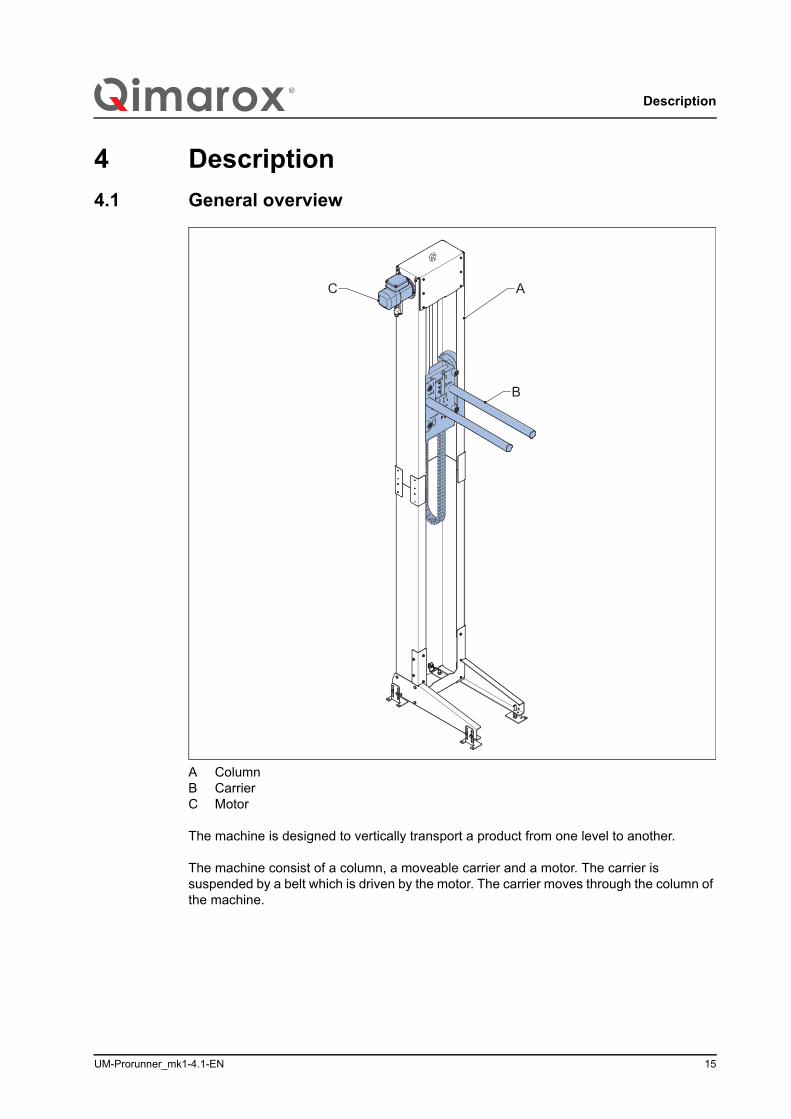
A ColumnB Carrier C Motor
The machine is designed to vertically transport a product from one level to another.
The machine consist of a column, a moveable carrier and a motor. The carrier is suspended by a belt which is driven by the motor. The carrier moves through the column of the machine.
B
AC
Description
16 UM-Prorunner_mk1-4.1-EN
4.2 Working principle
4.2.1 Product transportation
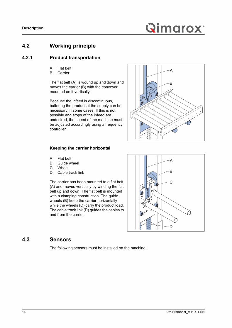
A Flat beltB Carrier
The flat belt (A) is wound up and down and moves the carrier (B) with the conveyor mounted on it vertically.
Because the infeed is discontinuous, buffering the product at the supply can be necessary in some cases. If this is not possible and stops of the infeed are undesired, the speed of the machine must be adjusted accordingly using a frequency controller.
Keeping the carrier horizontal
A Flat beltB Guide wheelC WheelD Cable track link
The carrier has been mounted to a flat belt (A) and moves vertically by winding the flat belt up and down. The flat belt is mounted with a clamping construction. The guide wheels (B) keep the carrier horizontally while the wheels (C) carry the product load. The cable track link (D) guides the cables to and from the carrier.
4.3 SensorsThe following sensors must be installed on the machine:
A
B
A
B
C
D
UM-Prorunner_mk1-4.1-EN 17
Description
/i
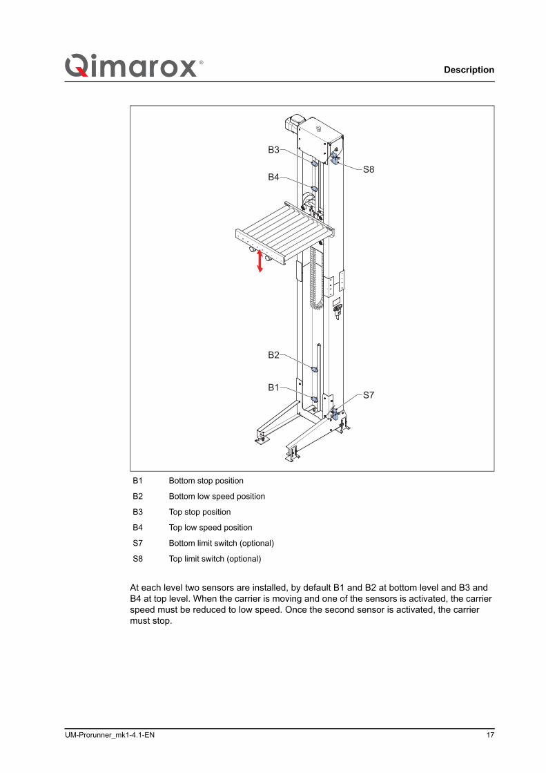
At each level two sensors are installed, by default B1 and B2 at bottom level and B3 and B4 at top level. When the carrier is moving and one of the sensors is activated, the carrier speed must be reduced to low speed. Once the second sensor is activated, the carrier must stop.
B1 Bottom stop position
B2 Bottom low speed position
B3 Top stop position
B4 Top low speed position
S7 Bottom limit switch (optional)
S8 Top limit switch (optional)
B1
B2
B4
B3
S8
S7
Description
18 UM-Prorunner_mk1-4.1-EN
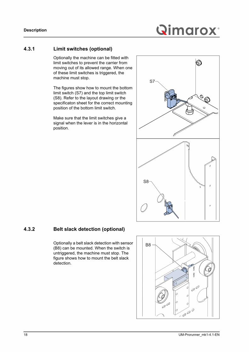
4.3.1 Limit switches (optional)Optionally the machine can be fitted with limit switches to prevent the carrier from moving out of its allowed range. When one of these limit switches is triggered, the machine must stop.
The figures show how to mount the bottom limit switch (S7) and the top limit switch (S8). Refer to the layout drawing or the specificaton sheet for the correct mounting position of the bottom limit switch.
Make sure that the limit switches give a signal when the lever is in the horizontal position.
4.3.2 Belt slack detection (optional)
Optionally a belt slack detection with sensor (B8) can be mounted. When the switch is untriggered, the machine must stop. The figure shows how to mount the belt slack detection.
S7
S8
B8
UM-Prorunner_mk1-4.1-EN 19
Description
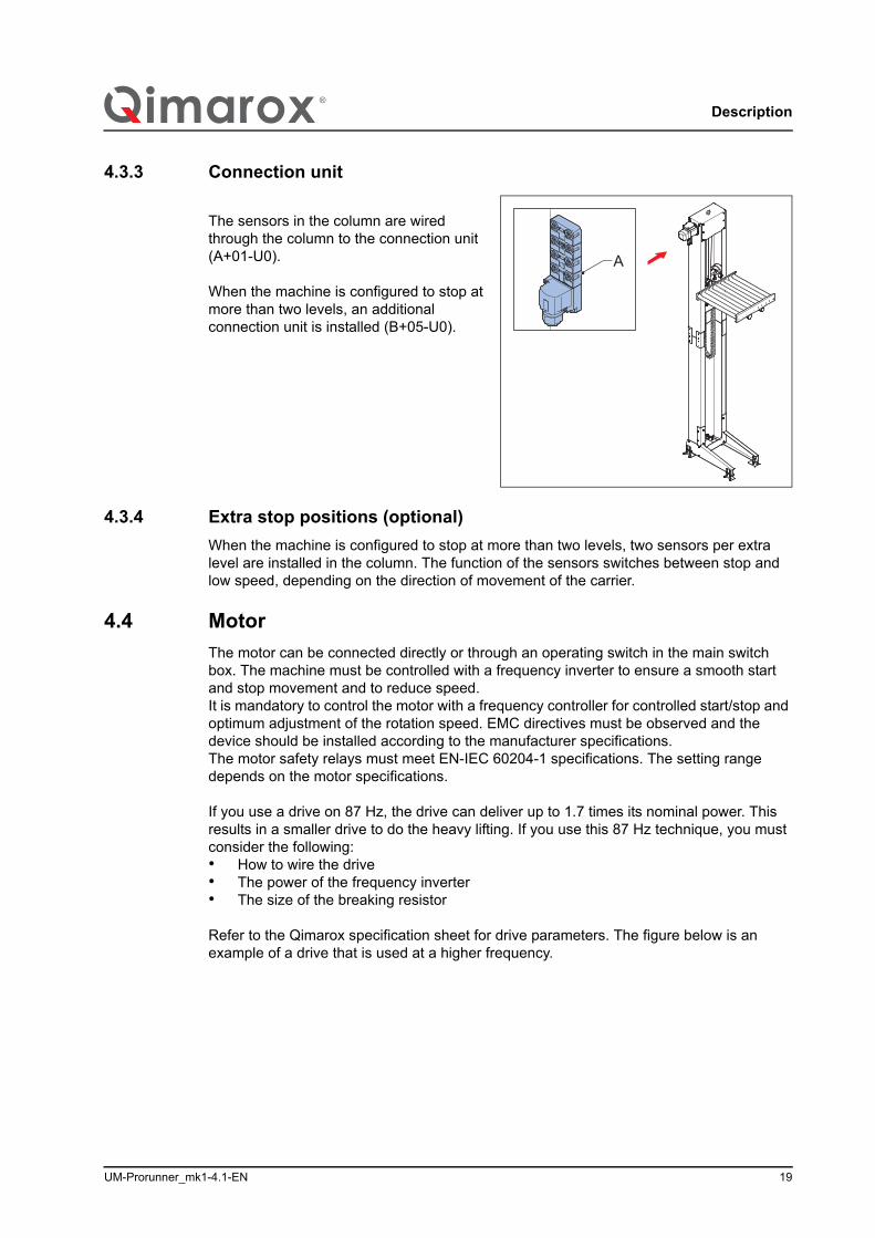
4.3.3 Connection unit
The sensors in the column are wired through the column to the connection unit (A+01-U0).
When the machine is configured to stop at more than two levels, an additional connection unit is installed (B+05-U0).
4.3.4 Extra stop positions (optional)When the machine is configured to stop at more than two levels, two sensors per extra level are installed in the column. The function of the sensors switches between stop and low speed, depending on the direction of movement of the carrier.
4.4 MotorThe motor can be connected directly or through an operating switch in the main switch box. The machine must be controlled with a frequency inverter to ensure a smooth start and stop movement and to reduce speed.It is mandatory to control the motor with a frequency controller for controlled start/stop and optimum adjustment of the rotation speed. EMC directives must be observed and the device should be installed according to the manufacturer specifications.The motor safety relays must meet EN-IEC 60204-1 specifications. The setting range depends on the motor specifications.
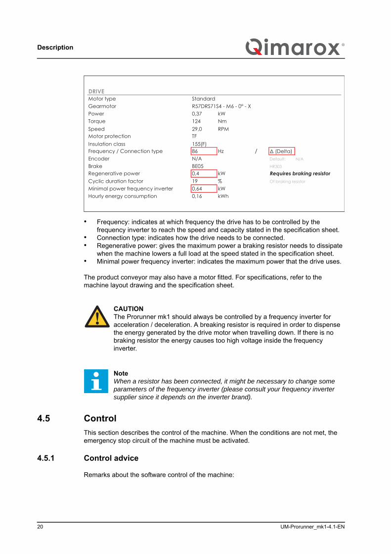
If you use a drive on 87 Hz, the drive can deliver up to 1.7 times its nominal power. This results in a smaller drive to do the heavy lifting. If you use this 87 Hz technique, you must consider the following:• How to wire the drive• The power of the frequency inverter• The size of the breaking resistor
Refer to the Qimarox specification sheet for drive parameters. The figure below is an example of a drive that is used at a higher frequency.
A
Description
20 UM-Prorunner_mk1-4.1-EN
• Frequency: indicates at which frequency the drive has to be controlled by the frequency inverter to reach the speed and capacity stated in the specification sheet.
• Connection type: indicates how the drive needs to be connected.• Regenerative power: gives the maximum power a braking resistor needs to dissipate
when the machine lowers a full load at the speed stated in the specification sheet.• Minimal power frequency inverter: indicates the maximum power that the drive uses.
The product conveyor may also have a motor fitted. For specifications, refer to the machine layout drawing and the specification sheet.
4.5 ControlThis section describes the control of the machine. When the conditions are not met, the emergency stop circuit of the machine must be activated.
4.5.1 Control advice
Remarks about the software control of the machine:
CAUTIONThe Prorunner mk1 should always be controlled by a frequency inverter for acceleration / deceleration. A breaking resistor is required in order to dispense the energy generated by the drive motor when travelling down. If there is no braking resistor the energy causes too high voltage inside the frequency inverter.
NoteWhen a resistor has been connected, it might be necessary to change some parameters of the frequency inverter (please consult your frequency inverter supplier since it depends on the inverter brand).
Standard
0,37 kW124 Nm29,0 RPMTF155(F)86 Hz / Δ (Delta)N/A Default: N/A
BE050,4 kW
Cyclic duration factor 19 %0,64 kW0,16 kWh
R57DRS71S4 - M6 - 0° - X
BrakeRegenerative power Requires braking resistor
Of braking resistor
Minimal power frequency inverter
Frequency / Connection typeEncoder
DRIVE
Torque
Motor protectionSpeed
HR303
Motor typeGearmotor
Insulation class
Power
Hourly energy consumption
UM-Prorunner_mk1-4.1-EN 21
Description
• Make sure that the products are fed to the machine with a spacing between them. If products run into each other, sufficient space must be created between these products on the transition to the infeed conveyor.
• Make sure that all the photocells and sensors (see chapter 4.3) have been adjusted correctly to the product and the carrier. Inaccurate settings can result in machine malfunction.
• The time it takes for the carrier to move from one level to another must be monitored by the software. If this time is exceeded, the machine must stop immediately.
• The time the in- or outfeed of a product takes must be monitored by the software. If this time is exceeded, the machine must stop immediately.
• A configuration with a cross transfer involves special control requirements.
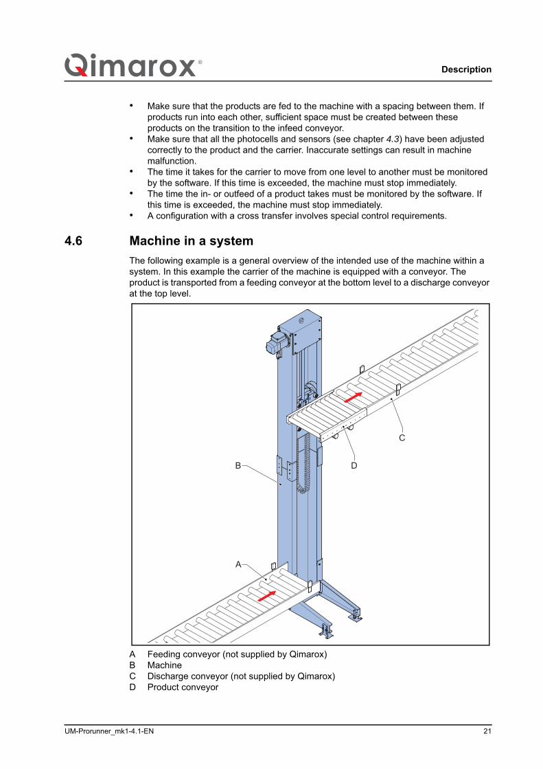
4.6 Machine in a systemThe following example is a general overview of the intended use of the machine within a system. In this example the carrier of the machine is equipped with a conveyor. The product is transported from a feeding conveyor at the bottom level to a discharge conveyor at the top level.
A Feeding conveyor (not supplied by Qimarox)B MachineC Discharge conveyor (not supplied by Qimarox)D Product conveyor
B
A
C
D
Description
22 UM-Prorunner_mk1-4.1-EN
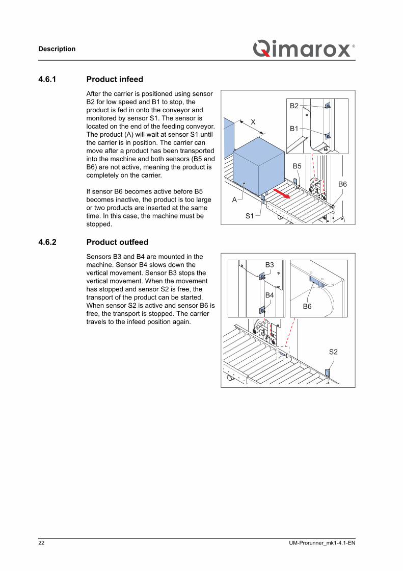
4.6.1 Product infeedAfter the carrier is positioned using sensor B2 for low speed and B1 to stop, the product is fed in onto the conveyor and monitored by sensor S1. The sensor is located on the end of the feeding conveyor. The product (A) will wait at sensor S1 until the carrier is in position. The carrier can move after a product has been transported into the machine and both sensors (B5 and B6) are not active, meaning the product is completely on the carrier.
If sensor B6 becomes active before B5 becomes inactive, the product is too large or two products are inserted at the same time. In this case, the machine must be stopped.
4.6.2 Product outfeedSensors B3 and B4 are mounted in the machine. Sensor B4 slows down the vertical movement. Sensor B3 stops the vertical movement. When the movement has stopped and sensor S2 is free, the transport of the product can be started. When sensor S2 is active and sensor B6 is free, the transport is stopped. The carrier travels to the infeed position again.
XB1
B2
S1
A
B5
B6
B6
B3
S2
B4
UM-Prorunner_mk1-4.1-EN 23
Description
4.7 SpecificationsThe information below together with the machine layout drawing and the specification sheet give specifications for the transportation of products.
4.7.1 Product transport specificationsRefer to the specification sheet for the product specifications that are applicable to your machine configuration.
Data concerning product type, dimensions, bottom sides and weights must always be verified with Qimarox. For example, moldable products in bags will usually not be transported along rollers, but along belts.
When permitted weight and distance deviate from the specifications in the machine layout drawing, the machine must be adjusted to accommodate this. These type of adjustments may only carried out by Qimarox or after written permission from Qimarox has been obtained.
If Qimarox does not supply the product conveyor, the weight of the applied conveyor needs to be checked by Qimarox to determine the correct drive on the vertical movement.
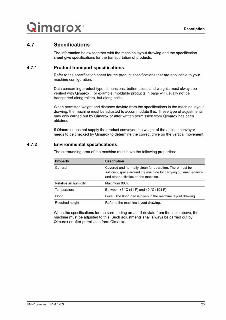
4.7.2 Environmental specificationsThe surrounding area of the machine must have the following properties:/i
When the specifications for the surrounding area still deviate from the table above, the machine must be adjusted to this. Such adjustments shall always be carried out by Qimarox or after permission from Qimarox.
Property Description
General Covered and normally clean for operation. There must be sufficient space around the machine for carrying out maintenance and other activities on the machine.
Relative air humidity Maximum 80%.
Temperature Between +5 °C (41 F) and 40 °C (104 F).
Floor Level. The floor load is given in the machine layout drawing.
Required height Refer to the machine layout drawing.
Installation
24 UM-Prorunner_mk1-4.1-EN
5 InstallationThis chapter describes installation instructions. Refer to the assembly manual for machine assembly instructions.
5.1 Delivery
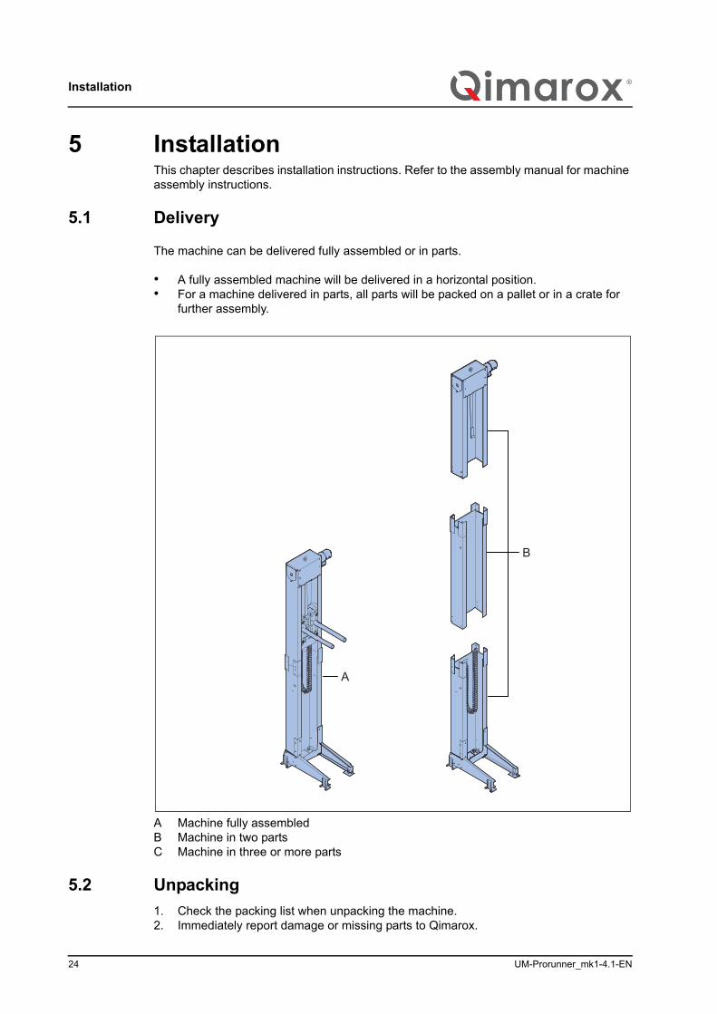
The machine can be delivered fully assembled or in parts.
• A fully assembled machine will be delivered in a horizontal position. • For a machine delivered in parts, all parts will be packed on a pallet or in a crate for
further assembly.
A Machine fully assembledB Machine in two partsC Machine in three or more parts
5.2 Unpacking1. Check the packing list when unpacking the machine.2. Immediately report damage or missing parts to Qimarox.
A
B
UM-Prorunner_mk1-4.1-EN 25
Installation
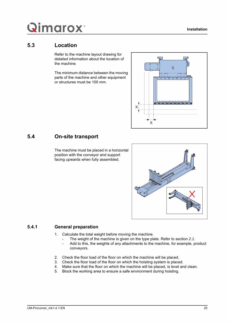
5.3 LocationRefer to the machine layout drawing for detailed information about the location of the machine.
The minimum distance between the moving parts of the machine and other equipment or structures must be 100 mm.
5.4 On-site transport
The machine must be placed in a horizontal position with the conveyor and support facing upwards when fully assembled.
5.4.1 General preparation1. Calculate the total weight before moving the machine.
- The weight of the machine is given on the type plate. Refer to section 2.1.- Add to this, the weights of any attachments to the machine, for example, product
conveyors.
2. Check the floor load of the floor on which the machine will be placed.3. Check the floor load of the floor on which the hoisting system is placed.4. Make sure that the floor on which the machine will be placed, is level and clean.5. Block the working area to ensure a safe environment during hoisting.
X
X
Installation
26 UM-Prorunner_mk1-4.1-EN
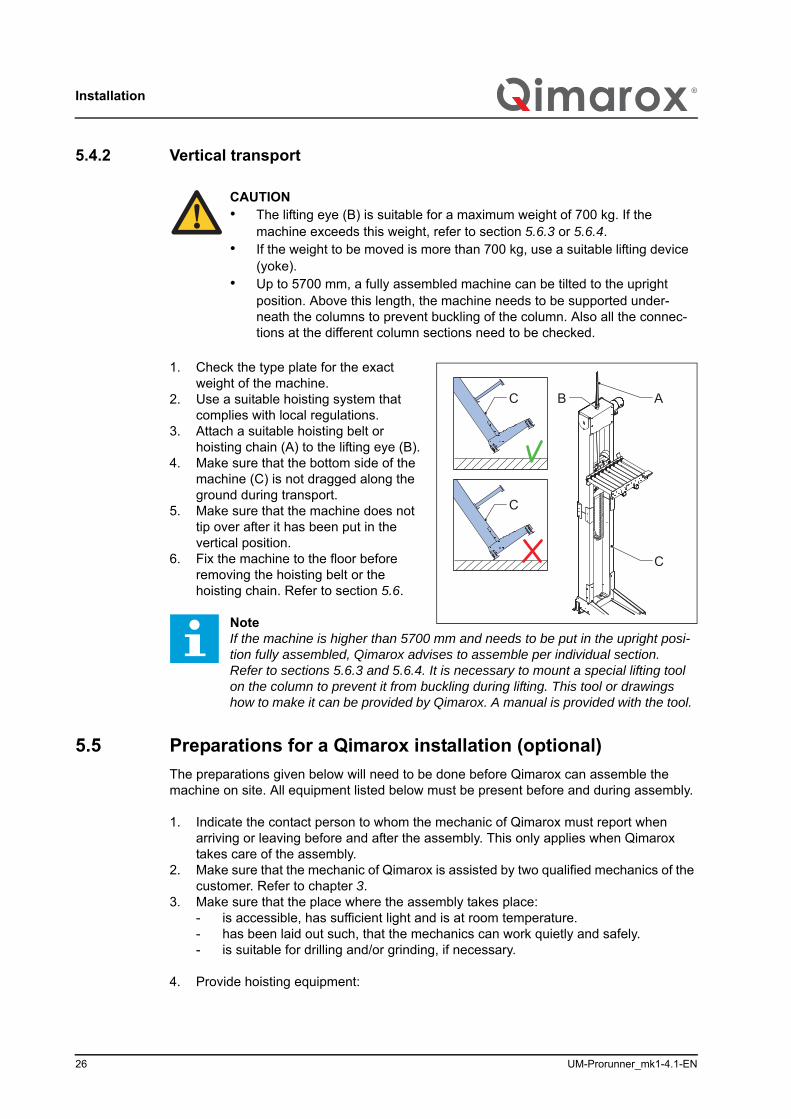
5.4.2 Vertical transport
1. Check the type plate for the exact weight of the machine.
2. Use a suitable hoisting system that complies with local regulations.
3. Attach a suitable hoisting belt or hoisting chain (A) to the lifting eye (B).
4. Make sure that the bottom side of the machine (C) is not dragged along the ground during transport.
5. Make sure that the machine does not tip over after it has been put in the vertical position.
6. Fix the machine to the floor before removing the hoisting belt or the hoisting chain. Refer to section 5.6.
5.5 Preparations for a Qimarox installation (optional)The preparations given below will need to be done before Qimarox can assemble the machine on site. All equipment listed below must be present before and during assembly.
1. Indicate the contact person to whom the mechanic of Qimarox must report when arriving or leaving before and after the assembly. This only applies when Qimarox takes care of the assembly.
2. Make sure that the mechanic of Qimarox is assisted by two qualified mechanics of the customer. Refer to chapter 3.
3. Make sure that the place where the assembly takes place:- is accessible, has sufficient light and is at room temperature.- has been laid out such, that the mechanics can work quietly and safely.- is suitable for drilling and/or grinding, if necessary.
4. Provide hoisting equipment:
CAUTION• The lifting eye (B) is suitable for a maximum weight of 700 kg. If the
machine exceeds this weight, refer to section 5.6.3 or 5.6.4.• If the weight to be moved is more than 700 kg, use a suitable lifting device
(yoke).• Up to 5700 mm, a fully assembled machine can be tilted to the upright
position. Above this length, the machine needs to be supported under-neath the columns to prevent buckling of the column. Also all the connec-tions at the different column sections need to be checked.
NoteIf the machine is higher than 5700 mm and needs to be put in the upright posi-tion fully assembled, Qimarox advises to assemble per individual section. Refer to sections 5.6.3 and 5.6.4. It is necessary to mount a special lifting tool on the column to prevent it from buckling during lifting. This tool or drawings how to make it can be provided by Qimarox. A manual is provided with the tool.
B A
C
C
C
UM-Prorunner_mk1-4.1-EN 27
Installation
- preferably a bridge crane with a minimum carrying capacity of 1.5 x the weight of the machine.
- or hoist with hoisting equipment with a minimum capacity of 2 x the weight of the machine.
5. Provide electric power (230 V AC) at a maximum of 5 meters from the place of assembly of the machine.
6. Provide the correct safety provisions:- Moveable scaffolding or a hydraulic hoist.- Personal protection equipment.
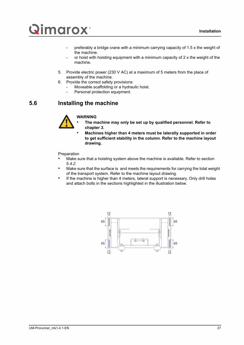
5.6 Installing the machine
Preparation• Make sure that a hoisting system above the machine is available. Refer to section
5.4.2.• Make sure that the surface is and meets the requirements for carrying the total weight
of the transport system. Refer to the machine layout drawing.• If the machine is higher than 4 meters, lateral support is necessary. Only drill holes
and attach bolts in the sections highlighted in the illustration below.
WARNING• The machine may only be set up by qualified personnel. Refer to
chapter 3.• Machines higher than 4 meters must be laterally supported in order
to get sufficient stability in the column. Refer to the machine layout drawing.
12
12
12
12
65
65
65
65
Installation
28 UM-Prorunner_mk1-4.1-EN
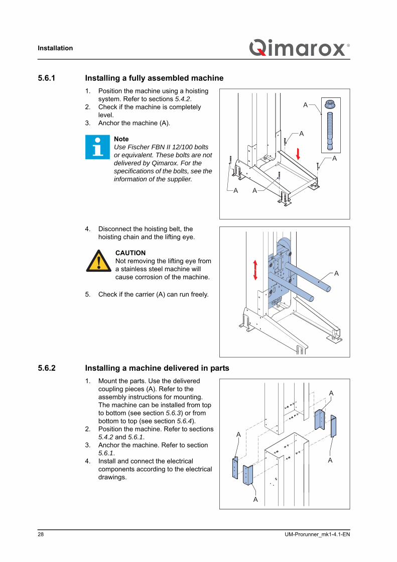
5.6.1 Installing a fully assembled machine 1. Position the machine using a hoisting
system. Refer to sections 5.4.2.2. Check if the machine is completely
level.3. Anchor the machine (A).
4. Disconnect the hoisting belt, the hoisting chain and the lifting eye.
5. Check if the carrier (A) can run freely.
5.6.2 Installing a machine delivered in parts1. Mount the parts. Use the delivered
coupling pieces (A). Refer to the assembly instructions for mounting. The machine can be installed from top to bottom (see section 5.6.3) or from bottom to top (see section 5.6.4).
2. Position the machine. Refer to sections 5.4.2 and 5.6.1.
3. Anchor the machine. Refer to section 5.6.1.
4. Install and connect the electrical components according to the electrical drawings.
NoteUse Fischer FBN II 12/100 bolts or equivalent. These bolts are not delivered by Qimarox. For the specifications of the bolts, see the information of the supplier.
A
A
A
AA
CAUTIONNot removing the lifting eye from a stainless steel machine will cause corrosion of the machine. A
A
A
A
A
UM-Prorunner_mk1-4.1-EN 29
Installation
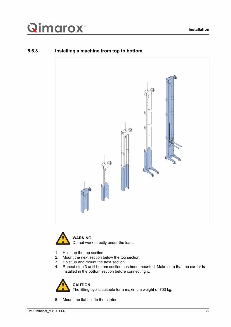
5.6.3 Installing a machine from top to bottom
1. Hoist up the top section.2. Mount the next section below the top section.3. Hoist up and mount the next section.4. Repeat step 3 until bottom section has been mounted. Make sure that the carrier is
installed in the bottom section before connecting it.
5. Mount the flat belt to the carrier.
WARNINGDo not work directly under the load.
CAUTIONThe lifting eye is suitable for a maximum weight of 700 kg.
Installation
30 UM-Prorunner_mk1-4.1-EN
6. Mount the conveyor.7. Remove the lifting eye.
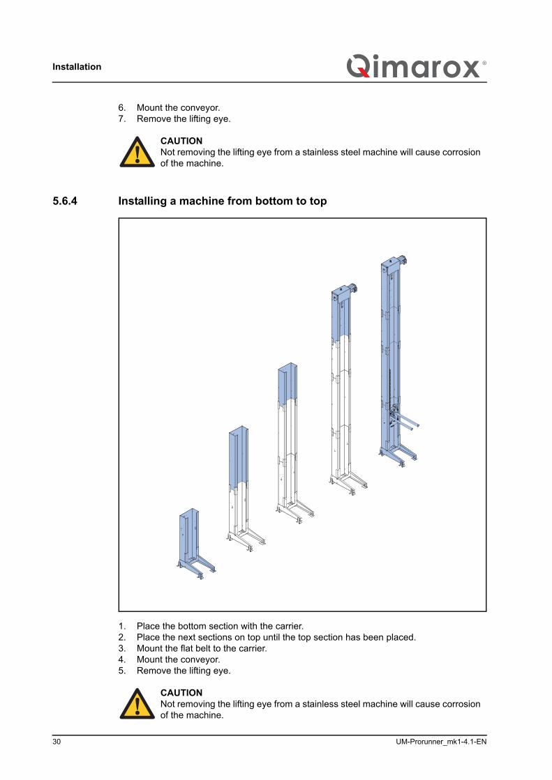
5.6.4 Installing a machine from bottom to top
1. Place the bottom section with the carrier.2. Place the next sections on top until the top section has been placed.3. Mount the flat belt to the carrier.4. Mount the conveyor.5. Remove the lifting eye.
CAUTIONNot removing the lifting eye from a stainless steel machine will cause corrosion of the machine.
CAUTIONNot removing the lifting eye from a stainless steel machine will cause corrosion of the machine.
UM-Prorunner_mk1-4.1-EN 31
Installation
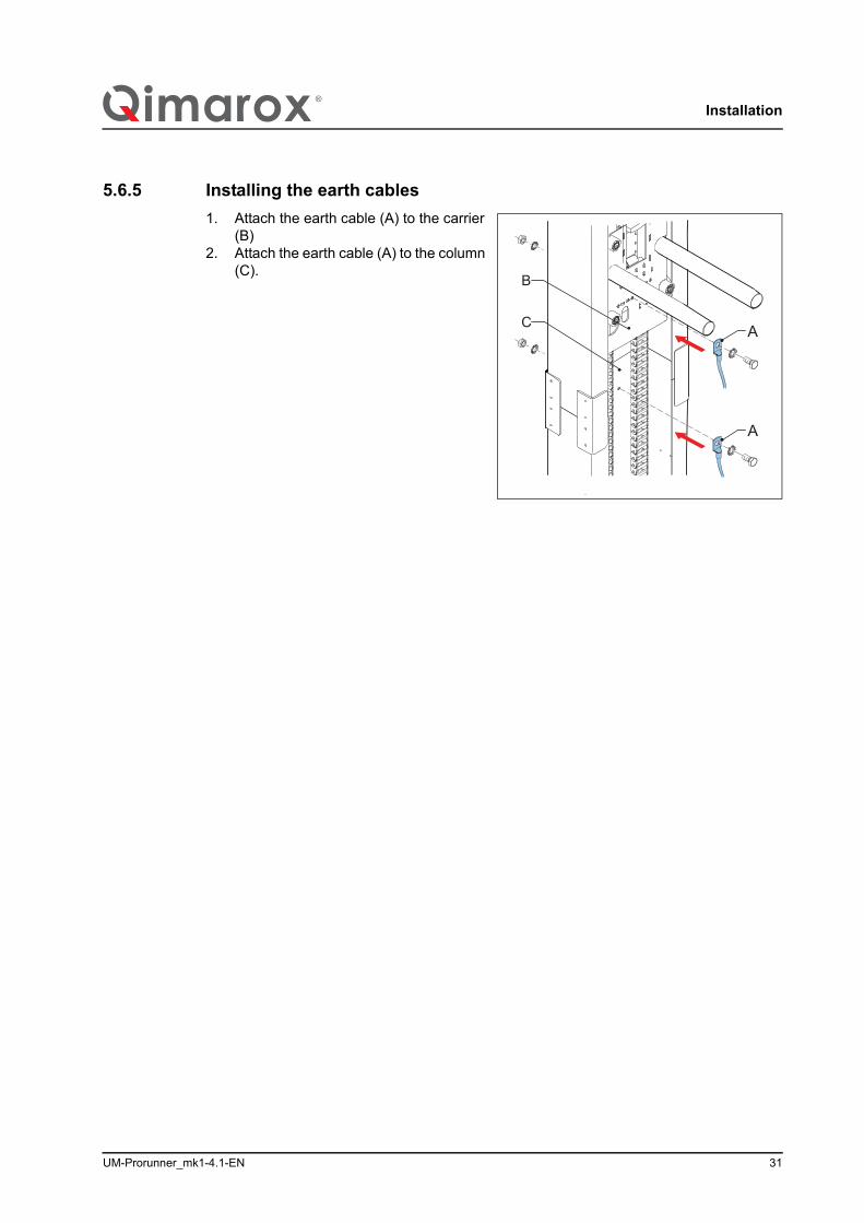
5.6.5 Installing the earth cables1. Attach the earth cable (A) to the carrier
(B)2. Attach the earth cable (A) to the column
(C).B
A
AC

Maintenance
32 UM-Prorunner_mk1-4.1-EN
6 Maintenance
6.1 Specific safety regulationsFor the proper functioning of the machine the various machine parts must be regularly maintained. In this way defects and inaccuracies of the machine are prevented.
CAUTION• The maintenance as described in this chapter is based on 2000 running
hours per year. Adjust the maintenance frequency to the actual number of running hours per year.
• If required, Qimarox can carry out the maintenance activities.
WARNING• Only a qualified maintenance engineer is allowed to carry out mainte-
nance activities on the machine. Refer to section 3.2.• Turn off the power supply to the machine with the main switch before
starting any maintenance or repair activities. Secure the main switch with a padlock.
• Insert the safety locking pin.• Do not use any corrosive and inflammable solvents or cleaning
agents on the machine that contain TRI, PER, TETRA or FCHC. Obey the instructions on the packaging when chemical substances (clean-ing agents), are used.
• After having completed maintenance activities, always put all safety provisions that have been removed in place again.
• Make sure that the machine always runs empty before carrying out any activities. No products may be present in the machine.
• Take the appropriate measures for safely working at heights.
UM-Prorunner_mk1-4.1-EN 33
Maintenance
6.2 Preventive maintenance schedule, machine excluding the transporter
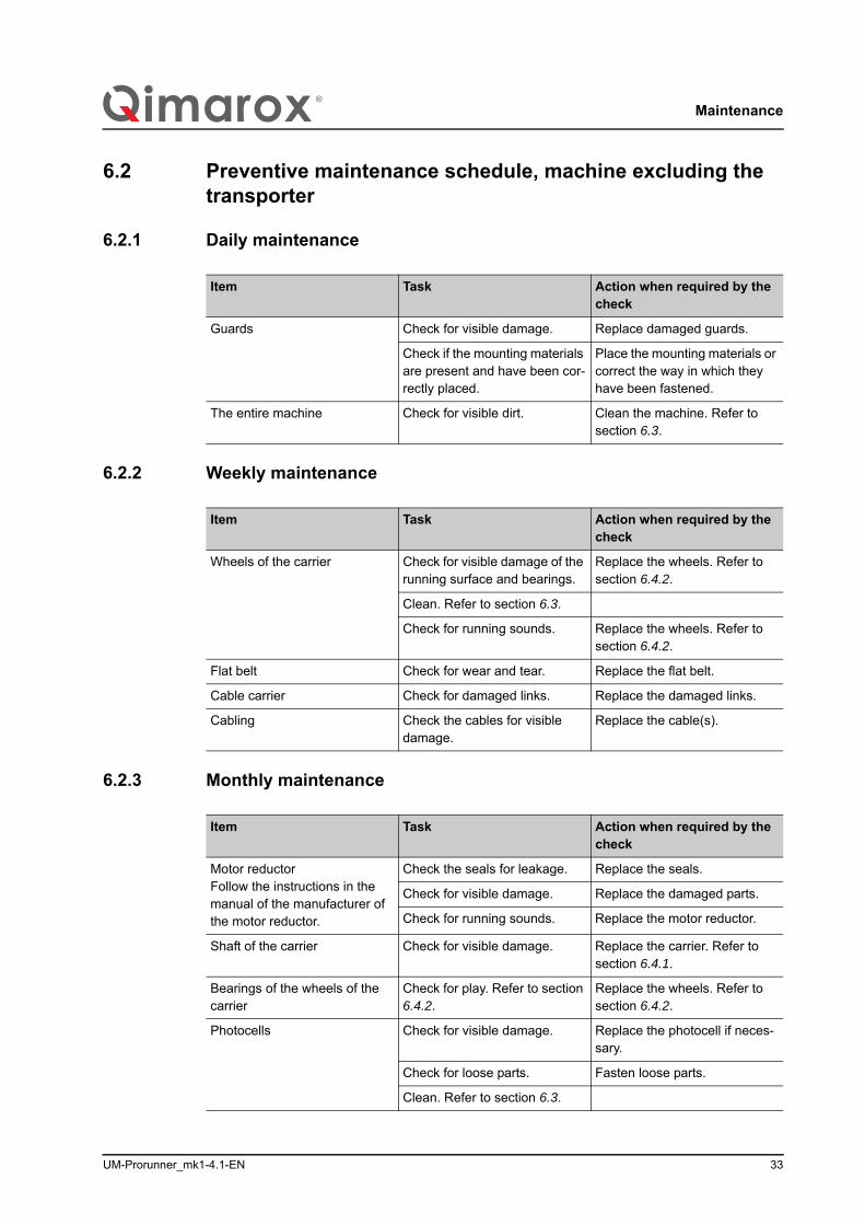
6.2.1 Daily maintenance/i
6.2.2 Weekly maintenance/i
6.2.3 Monthly maintenance/i
Item Task Action when required by the check
Guards Check for visible damage. Replace damaged guards.
Check if the mounting materials are present and have been cor-rectly placed.
Place the mounting materials or correct the way in which they have been fastened.
The entire machine Check for visible dirt. Clean the machine. Refer to section 6.3.
Item Task Action when required by the check
Wheels of the carrier Check for visible damage of the running surface and bearings.
Replace the wheels. Refer to section 6.4.2.
Clean. Refer to section 6.3.
Check for running sounds. Replace the wheels. Refer to section 6.4.2.
Flat belt Check for wear and tear. Replace the flat belt.
Cable carrier Check for damaged links. Replace the damaged links.
Cabling Check the cables for visible damage.
Replace the cable(s).
Item Task Action when required by the check
Motor reductorFollow the instructions in the manual of the manufacturer of the motor reductor.
Check the seals for leakage. Replace the seals.
Check for visible damage. Replace the damaged parts.
Check for running sounds. Replace the motor reductor.
Shaft of the carrier Check for visible damage. Replace the carrier. Refer to section 6.4.1.
Bearings of the wheels of the carrier
Check for play. Refer to section 6.4.2.
Replace the wheels. Refer to section 6.4.2.
Photocells Check for visible damage. Replace the photocell if neces-sary.
Check for loose parts. Fasten loose parts.
Clean. Refer to section 6.3.
Maintenance
34 UM-Prorunner_mk1-4.1-EN
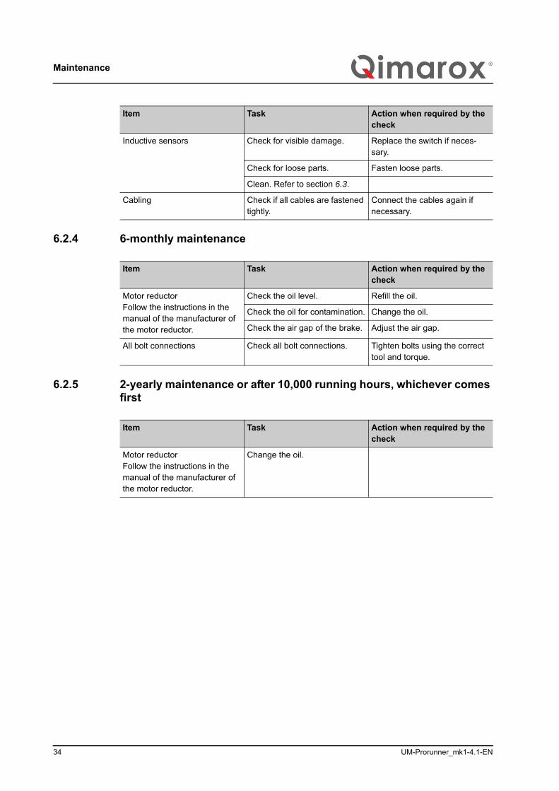
6.2.4 6-monthly maintenance/i
6.2.5 2-yearly maintenance or after 10,000 running hours, whichever comes first/i
Inductive sensors Check for visible damage. Replace the switch if neces-sary.
Check for loose parts. Fasten loose parts.
Clean. Refer to section 6.3.
Cabling Check if all cables are fastened tightly.
Connect the cables again if necessary.
Item Task Action when required by the check
Item Task Action when required by the check
Motor reductorFollow the instructions in the manual of the manufacturer of the motor reductor.
Check the oil level. Refill the oil.
Check the oil for contamination. Change the oil.
Check the air gap of the brake. Adjust the air gap.
All bolt connections Check all bolt connections. Tighten bolts using the correct tool and torque.
Item Task Action when required by the check
Motor reductorFollow the instructions in the manual of the manufacturer of the motor reductor.
Change the oil.

UM-Prorunner_mk1-4.1-EN 35
Maintenance
6.3 Cleaning
1. Place the safety locking pin and ensure that the carrier is resting on the pin to prevent the carrier from falling down.
2. Switch off the machine.3. Secure the main power supply switch with a padlock.4. Remove deposit and dirt by hand.5. Report any damage to the technically responsible person or to Qimarox and make
sure that any damage is remedied before restarting the machine.
CAUTION• Do not use any corrosive and inflammable solvents or cleaning agents on
the machine that contain TRI, PER, TETRA or FCHC. Read the instruc-tions on the packaging when chemical substances (cleaning agents) are used.
• Electrical components should not make contact with water or other liquids.• Do not clean the machine with water under high pressure.• Avoid parts made of rubber or plastic, such as cables and gaskets, from
making contact with oil, solvents or other chemicals.
Maintenance
36 UM-Prorunner_mk1-4.1-EN
6.4 Replace partsSome machine parts are subject to wear. See the type plate and the exploded view for the specifications of the machine parts.
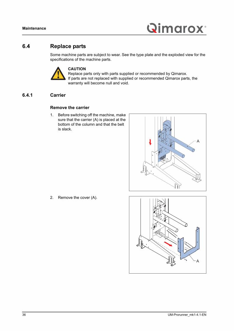
6.4.1 Carrier
Remove the carrier1. Before switching off the machine, make
sure that the carrier (A) is placed at the bottom of the column and that the belt is slack.
2. Remove the cover (A).
CAUTIONReplace parts only with parts supplied or recommended by Qimarox.If parts are not replaced with supplied or recommended Qimarox parts, the warranty will become null and void.
A
A
UM-Prorunner_mk1-4.1-EN 37
Maintenance
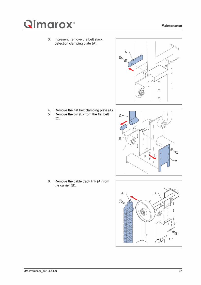
3. If present, remove the belt slack detection clamping plate (A).
4. Remove the flat belt clamping plate (A).5. Remove the pin (B) from the flat belt
(C).
6. Remove the cable track link (A) from the carrier (B).
A
C
B
A
A B
Maintenance
38 UM-Prorunner_mk1-4.1-EN
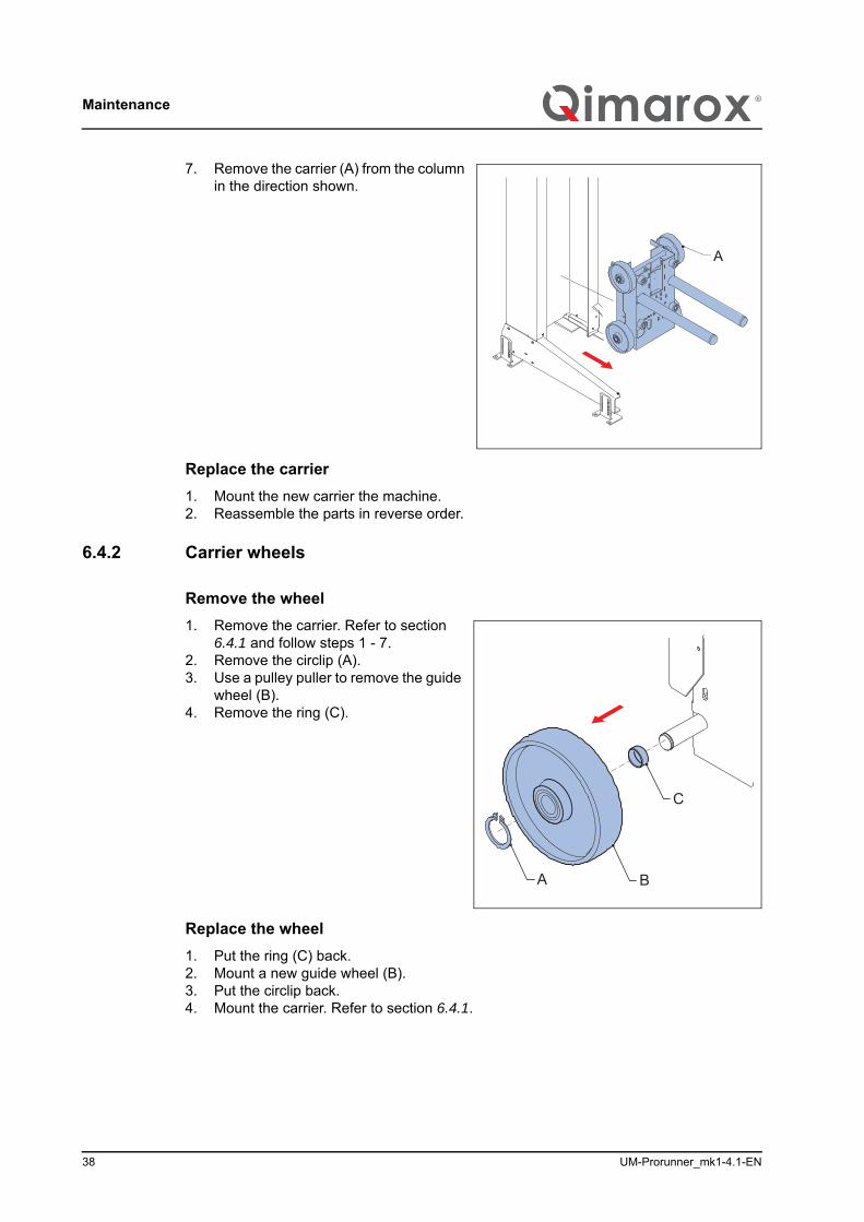
7. Remove the carrier (A) from the column in the direction shown.
Replace the carrier1. Mount the new carrier the machine.2. Reassemble the parts in reverse order.
6.4.2 Carrier wheels
Remove the wheel1. Remove the carrier. Refer to section
6.4.1 and follow steps 1 - 7.2. Remove the circlip (A).3. Use a pulley puller to remove the guide
wheel (B).4. Remove the ring (C).
Replace the wheel1. Put the ring (C) back.2. Mount a new guide wheel (B).3. Put the circlip back.4. Mount the carrier. Refer to section 6.4.1.
A
A B
C
UM-Prorunner_mk1-4.1-EN 39
Maintenance
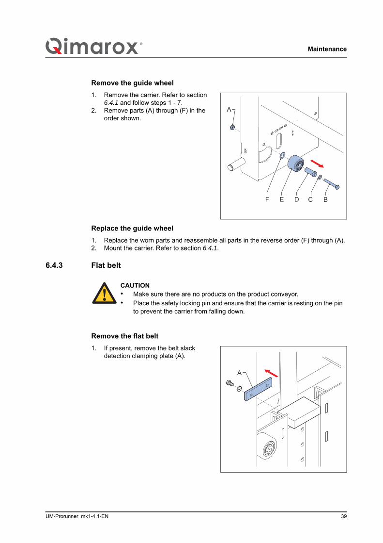
Remove the guide wheel1. Remove the carrier. Refer to section
6.4.1 and follow steps 1 - 7.2. Remove parts (A) through (F) in the
order shown.
Replace the guide wheel1. Replace the worn parts and reassemble all parts in the reverse order (F) through (A).2. Mount the carrier. Refer to section 6.4.1.
6.4.3 Flat belt
Remove the flat belt1. If present, remove the belt slack
detection clamping plate (A).
BDEF C
A
CAUTION• Make sure there are no products on the product conveyor.• Place the safety locking pin and ensure that the carrier is resting on the pin
to prevent the carrier from falling down.
A
Maintenance
40 UM-Prorunner_mk1-4.1-EN
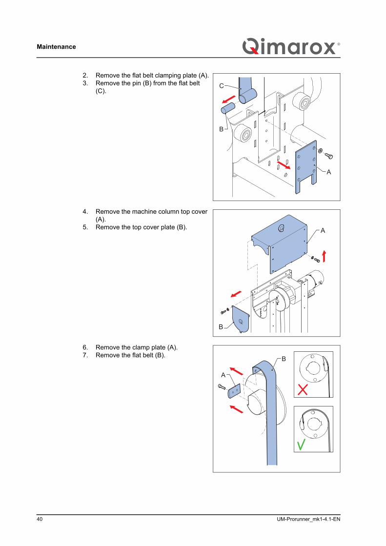
2. Remove the flat belt clamping plate (A).3. Remove the pin (B) from the flat belt
(C).
4. Remove the machine column top cover (A).
5. Remove the top cover plate (B).
6. Remove the clamp plate (A).7. Remove the flat belt (B).
C
B
A
A
B
B
A
UM-Prorunner_mk1-4.1-EN 41
Maintenance
Replace the flat belt1. Replace the worn flat belt.2. Reassemble the parts in reverse order.
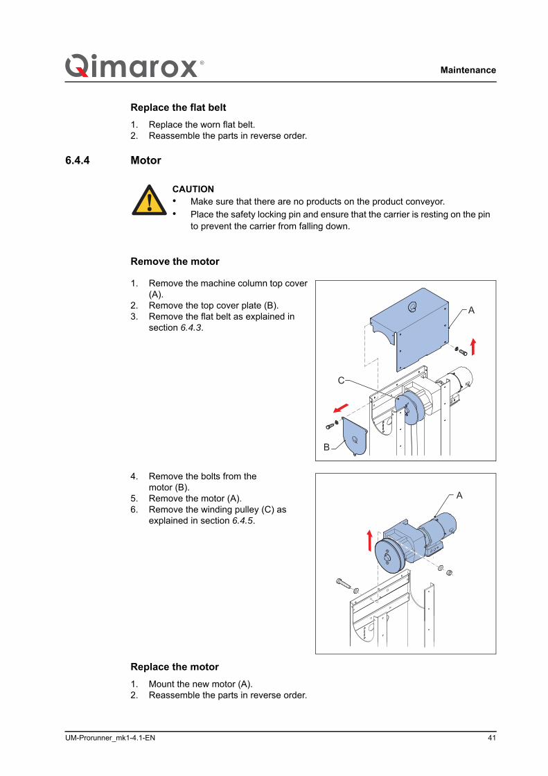
6.4.4 Motor
Remove the motor
1. Remove the machine column top cover (A).
2. Remove the top cover plate (B).3. Remove the flat belt as explained in
section 6.4.3.
4. Remove the bolts from the motor (B).
5. Remove the motor (A). 6. Remove the winding pulley (C) as
explained in section 6.4.5.
Replace the motor1. Mount the new motor (A).2. Reassemble the parts in reverse order.
CAUTION• Make sure that there are no products on the product conveyor.• Place the safety locking pin and ensure that the carrier is resting on the pin
to prevent the carrier from falling down.
A
B
C
A
Maintenance
42 UM-Prorunner_mk1-4.1-EN
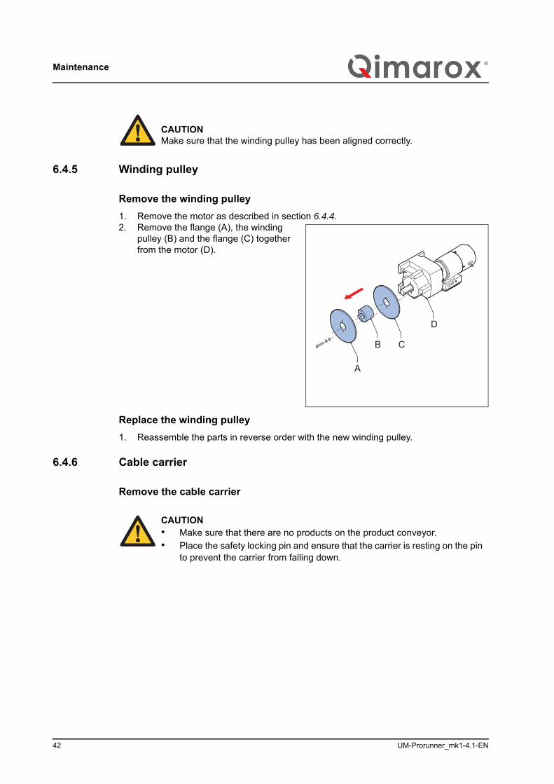
6.4.5 Winding pulley
Remove the winding pulley1. Remove the motor as described in section 6.4.4.2. Remove the flange (A), the winding
pulley (B) and the flange (C) together from the motor (D).
Replace the winding pulley1. Reassemble the parts in reverse order with the new winding pulley.
6.4.6 Cable carrier
Remove the cable carrier
CAUTIONMake sure that the winding pulley has been aligned correctly.
A
C
D
B
CAUTION• Make sure that there are no products on the product conveyor.• Place the safety locking pin and ensure that the carrier is resting on the pin
to prevent the carrier from falling down.
UM-Prorunner_mk1-4.1-EN 43
Maintenance
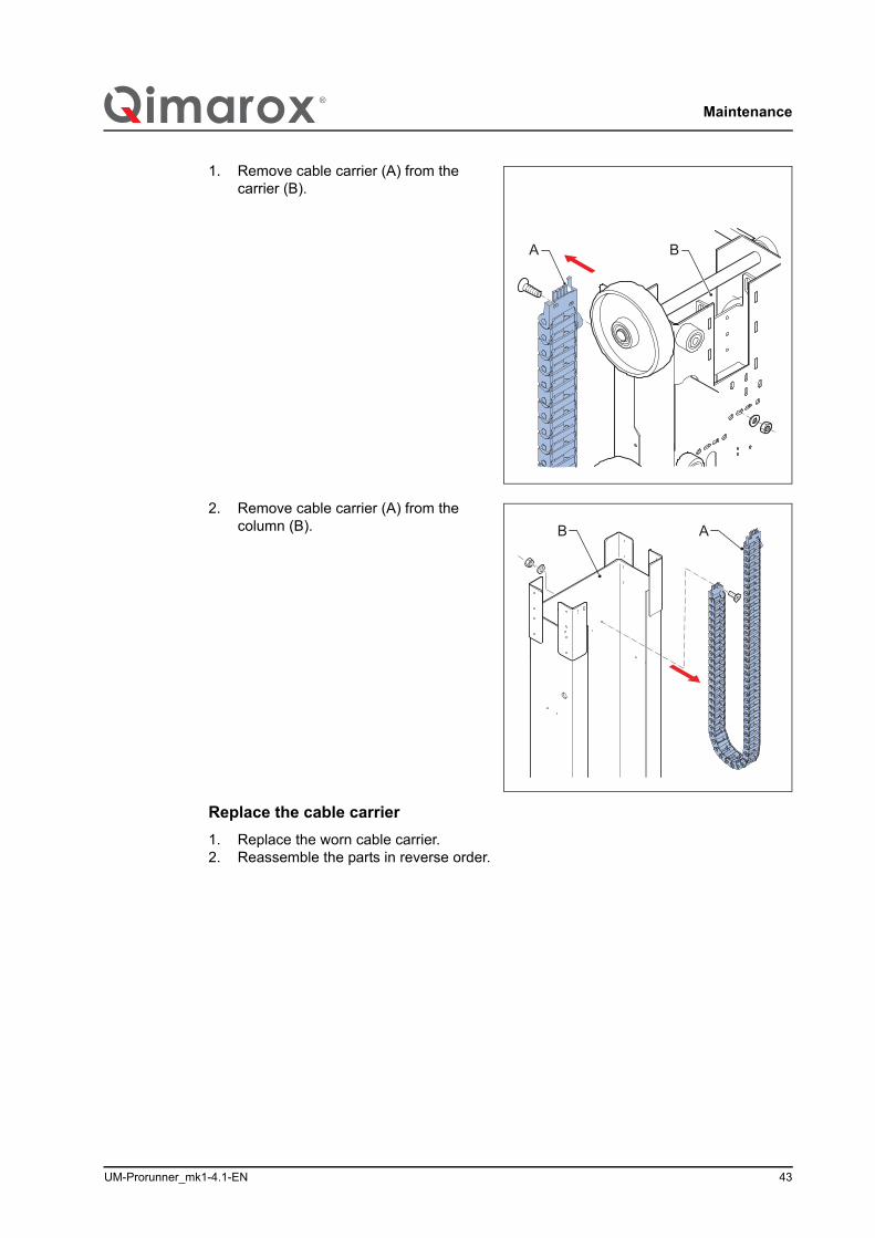
1. Remove cable carrier (A) from the carrier (B).
2. Remove cable carrier (A) from the column (B).
Replace the cable carrier1. Replace the worn cable carrier.2. Reassemble the parts in reverse order.
A B
AB
Troubleshooting
44 UM-Prorunner_mk1-4.1-EN
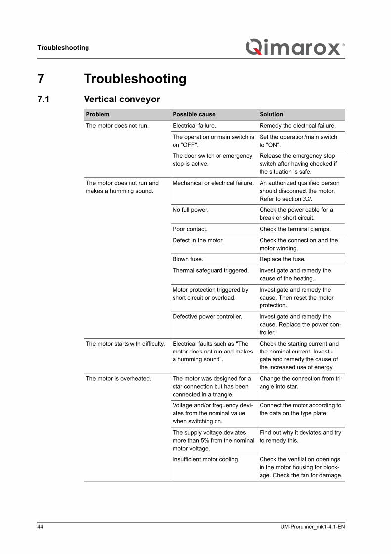
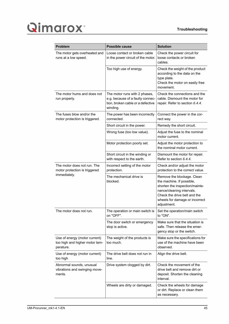
7 Troubleshooting7.1 Vertical conveyor
Problem Possible cause Solution
The motor does not run. Electrical failure. Remedy the electrical failure.
The operation or main switch is on "OFF".
Set the operation/main switch to "ON".
The door switch or emergency stop is active.
Release the emergency stop switch after having checked if the situation is safe.
The motor does not run and makes a humming sound.
Mechanical or electrical failure. An authorized qualified person should disconnect the motor. Refer to section 3.2.
No full power. Check the power cable for a break or short circuit.
Poor contact. Check the terminal clamps.
Defect in the motor. Check the connection and the motor winding.
Blown fuse. Replace the fuse.
Thermal safeguard triggered. Investigate and remedy the cause of the heating.
Motor protection triggered by short circuit or overload.
Investigate and remedy the cause. Then reset the motor protection.
Defective power controller. Investigate and remedy the cause. Replace the power con-troller.
The motor starts with difficulty. Electrical faults such as "The motor does not run and makes a humming sound".
Check the starting current and the nominal current. Investi-gate and remedy the cause of the increased use of energy.
The motor is overheated. The motor was designed for a star connection but has been connected in a triangle.
Change the connection from tri-angle into star.
Voltage and/or frequency devi-ates from the nominal value when switching on.
Connect the motor according to the data on the type plate.
The supply voltage deviates more than 5% from the nominal motor voltage.
Find out why it deviates and try to remedy this.
Insufficient motor cooling. Check the ventilation openings in the motor housing for block-age. Check the fan for damage.
UM-Prorunner_mk1-4.1-EN 45
Troubleshooting
The motor gets overheated and runs at a low speed.
Loose contact or broken cable in the power circuit of the motor.
Check the power circuit for loose contacts or broken cables.
Too high use of energy. Check the weight of the product according to the data on the type plate.Check the motor on easily free movement.
The motor hums and does not run properly.
The motor runs with 2 phases, e.g. because of a faulty connec-tion, broken cable or a defective winding.
Check the connections and the cable. Dismount the motor for repair. Refer to section 6.4.4.
The fuses blow and/or the motor protection is triggered.
The power has been incorrectly connected.
Connect the power in the cor-rect way.
Short circuit in the power. Remedy the short circuit.
Wrong fuse (too low value). Adjust the fuse to the nominal motor current.
Motor protection poorly set. Adjust the motor protection to the nominal motor current.
Short circuit in the winding or with respect to the earth.
Dismount the motor for repair. Refer to section 6.4.4.
The motor does not run. The motor protection is triggered immediately.
Incorrect setting of the motor protection.
Check and/or adjust the motor protection to the correct value.
The mechanical drive is blocked.
Remove the blockage. Clean the machine. If possible, shorten the inspection/mainte-nance/cleaning intervals. Check the drive belt and the wheels for damage or incorrect adjustment.
The motor does not run. The operation or main switch is on "OFF".
Set the operation/main switch to "ON".
The door switch or emergency stop is active.
Make sure that the situation is safe. Then release the emer-gency stop or the switch.
Use of energy (motor current) too high and higher motor tem-perature.
The weight of the products is too much.
Make sure the specifications for use of the machine have been observed.
Use of energy (motor current) too high
The drive belt does not run in line.
Align the drive belt.
Abnormal sounds, unusual vibrations and swinging move-ments.
Drive system clogged by dirt. Check the movement of the drive belt and remove dirt or deposit. Shorten the cleaning interval.
Wheels are dirty or damaged. Check the wheels for damage or dirt. Replace or clean them as necessary.
Problem Possible cause Solution
CE declaration of conformity
46 UM-Prorunner_mk1-4.1-EN
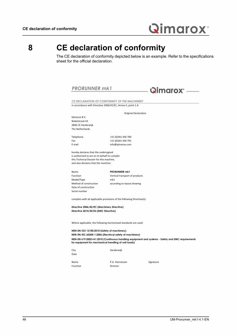
8 CE declaration of conformityThe CE declaration of conformity depicted below is an example. Refer to the specifications sheet for the official declaration.
UM-Prorunner_mk1-4.1-EN 47
Exploded views
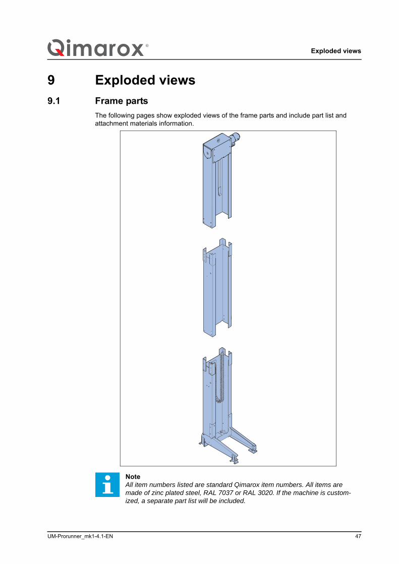
9 Exploded views9.1 Frame parts
The following pages show exploded views of the frame parts and include part list and attachment materials information.
NoteAll item numbers listed are standard Qimarox item numbers. All items are made of zinc plated steel, RAL 7037 or RAL 3020. If the machine is custom-ized, a separate part list will be included.
Exploded views
48 UM-Prorunner_mk1-4.1-EN
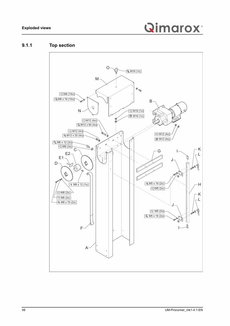
9.1.1 Top section
B
CE2
D
A
M
N
O
G ILK
J
M8 (2x)
M8 x 70 (2x)
M8 (2x)
M8 x 12 (1x)
F
M12 (4x)M12 x 20 (4x)
M12 x 60 (4x)M12 (4x)
M6 (3x)M6 x 12 (3x)
H
M16 (1x)
M8 (14x)
M8 x 16 (14x)
M16 (1x)
M16 (1x)
M5 (2x)
M5 x 16 (2x)
I
M5 x 16 (2x)
M5 (2x)
E1
JLK
M12 (4x)
M12 (4x)
UM-Prorunner_mk1-4.1-EN 49
Exploded views
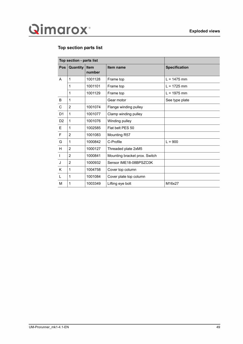
Top section parts list/i
Top section - parts list
Pos Quantity Itemnumber
Item name Specification
A 1 1001128 Frame top L = 1475 mm
1 1001101 Frame top L = 1725 mm
1 1001129 Frame top L = 1975 mm
B 1 Gear motor See type plate
C 2 1001074 Flange winding pulley
D1 1 1001077 Clamp winding pulley
D2 1 1001076 Winding pulley
E 1 1002585 Flat belt PES 50
F 2 1001083 Mounting R57
G 1 1000842 C-Profile L = 900
H 2 1000127 Threaded plate 2xM5
I 2 1000841 Mounting bracket prox. Switch
J 2 1000932 Sensor IME18-08BPSZC0K
K 1 1004758 Cover top column
L 1 1001084 Cover plate top column
M 1 1003349 Lifting eye bolt M16x27
Exploded views
50 UM-Prorunner_mk1-4.1-EN
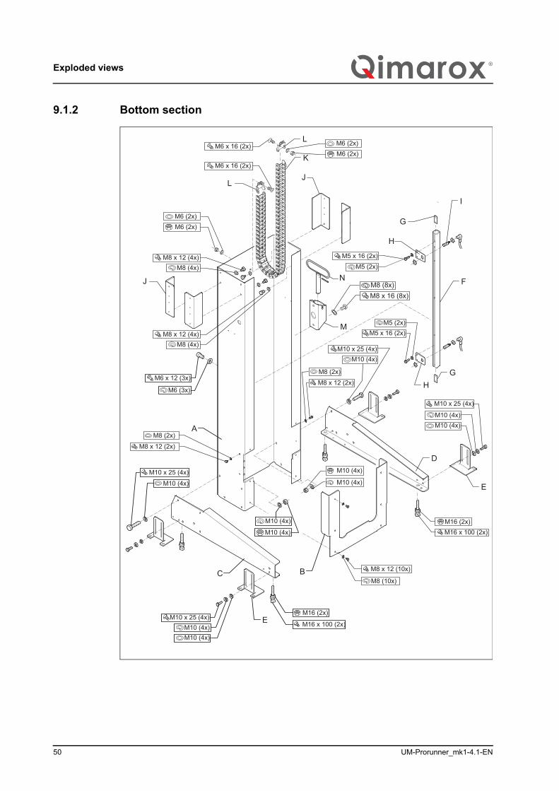
9.1.2 Bottom section
M6 (2x)
F
M5 x 16 (2x)M5 (2x)
H
I
G
M8 (10x)
M8 x 12 (10x)B
A
M16 x 100 (2x)
M16 (2x)
M16 (2x)M16 x 100 (2x)
M10 (4x)
M10 (4x)
M10 (4x)
M10 (4x)M10 x 25 (4x)
M10 (4x)
M10 (4x)M10 x 25 (4x)
M10 (4x)
M10 x 25 (4x)
M10 (4x)
C
D
E
E
M10 (4x)
M10 x 25 (4x)M10 (4x)
M5 x 16 (2x)M5 (2x)
M6 x 12 (3x)
M6 (3x)
J
LJ
M
N
K
HG
L
M8 (8x)M8 x 16 (8x)
M8 x 12 (2x)
M8 (2x)
M8 x 12 (2x)
M8 (2x)
M6 (2x)
M8 (4x)M8 x 12 (4x)
M6 x 16 (2x)
M8 (4x)M8 x 12 (4x)
M6 x 16 (2x)M6 (2x)M6 (2x)
UM-Prorunner_mk1-4.1-EN 51
Exploded views
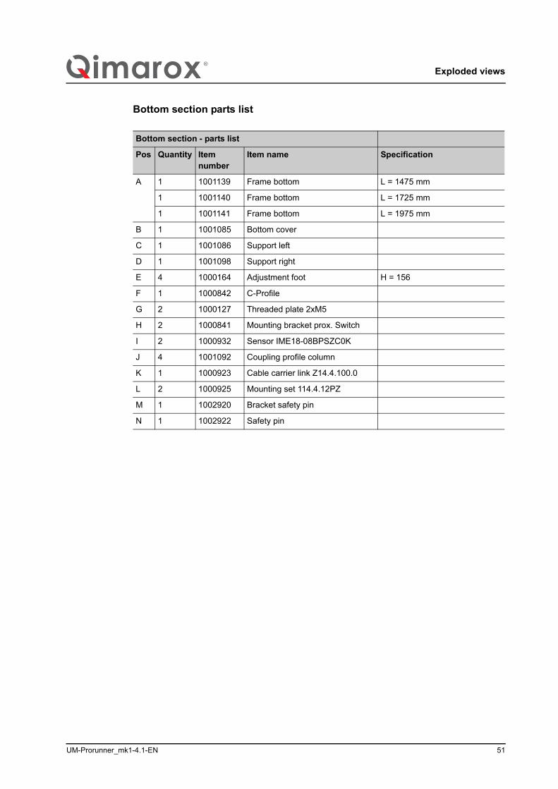
Bottom section parts list/i
Bottom section - parts list
Pos Quantity Itemnumber
Item name Specification
A 1 1001139 Frame bottom L = 1475 mm
1 1001140 Frame bottom L = 1725 mm
1 1001141 Frame bottom L = 1975 mm
B 1 1001085 Bottom cover
C 1 1001086 Support left
D 1 1001098 Support right
E 4 1000164 Adjustment foot H = 156
F 1 1000842 C-Profile
G 2 1000127 Threaded plate 2xM5
H 2 1000841 Mounting bracket prox. Switch
I 2 1000932 Sensor IME18-08BPSZC0K
J 4 1001092 Coupling profile column
K 1 1000923 Cable carrier link Z14.4.100.0
L 2 1000925 Mounting set 114.4.12PZ
M 1 1002920 Bracket safety pin
N 1 1002922 Safety pin
Exploded views
52 UM-Prorunner_mk1-4.1-EN
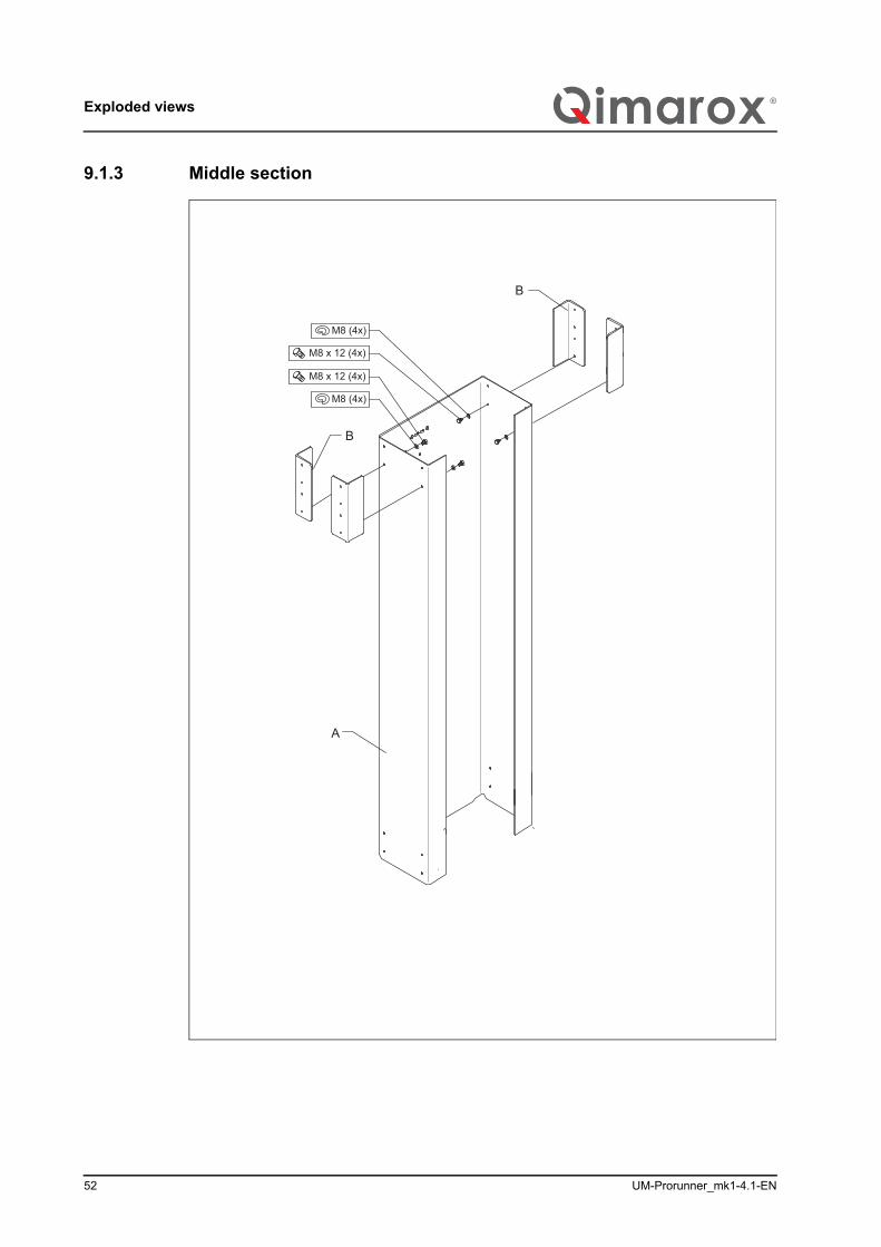
9.1.3 Middle section
M8 x 12 (4x)
M8 (4x)
M8 x 12 (4x)
M8 (4x)
B
B
A
UM-Prorunner_mk1-4.1-EN 53
Exploded views
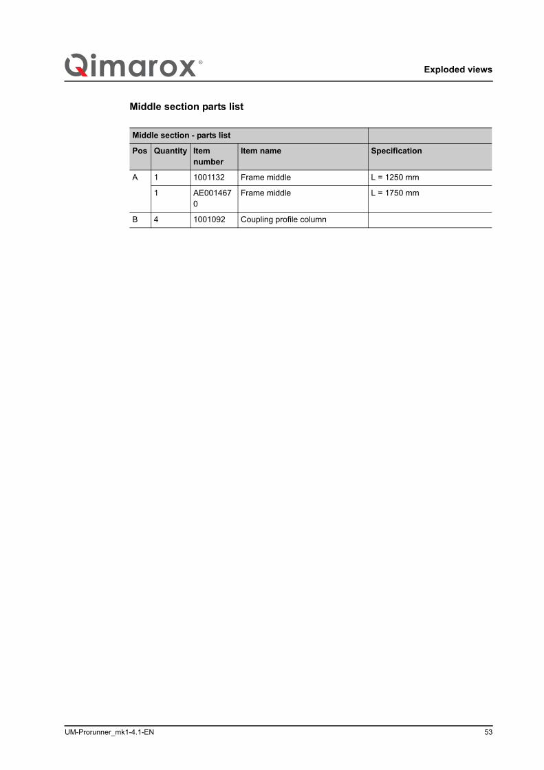
Middle section parts list/i
Middle section - parts list
Pos Quantity Itemnumber
Item name Specification
A 1 1001132 Frame middle L = 1250 mm
1 AE0014670
Frame middle L = 1750 mm
B 4 1001092 Coupling profile column
Exploded views
54 UM-Prorunner_mk1-4.1-EN
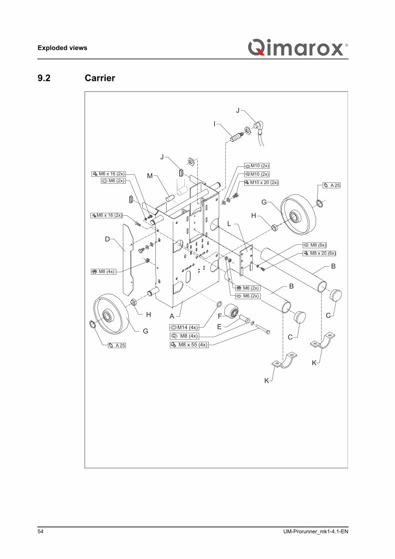
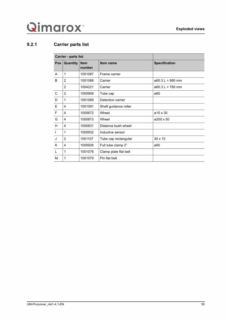
9.2 Carrier
M10 (2x)
M10 x 20 (2x)
M10 (2x)M6 (2x)
M6 x 16 (2x)
A 25
A 25
M8 x 20 (6x)
M8 (6x)
C
B
B
C
A
G
H
G
H
I
J
D
J
K
K
LM6 x 16 (2x)
M6 (2x)
M6 (2x)
M8 (4x)
M
FEM14 (4x)
M8 (4x)
M8 x 55 (4x)
UM-Prorunner_mk1-4.1-EN 55
Exploded views
9.2.1 Carrier parts list/i
Carrier - parts list
Pos Quantity Itemnumber
Item name Specification
A 1 1001087 Frame carrier
B 2 1001088 Carrier ø60.3 L = 995 mm
2 1004221 Carrier ø60.3 L = 780 mm
C 2 1000909 Tube cap ø60
D 1 1001089 Detection carrier
E 4 1001091 Shaft guidance roller
F 4 1000672 Wheel ø15 x 30
G 4 1000873 Wheel ø200 x 50
H 4 1000831 Distance bush wheel
I 1 1000932 Inductive sensor
J 2 1001107 Tube cap rectangular 30 x 10
K 4 1000926 Full tube clamp 2” ø60
L 1 1001078 Clamp plate flat belt
M 1 1001079 Pin flat belt
Exploded views
56 UM-Prorunner_mk1-4.1-EN
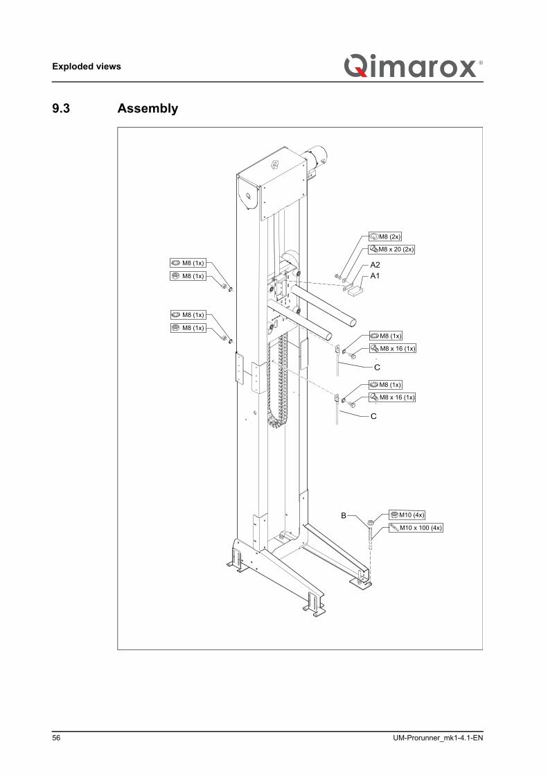
9.3 Assembly
B
A1A2
M8 x 20 (2x)
M8 (2x)
M10 x 100 (4x)
M10 (4x)
M8 (1x)
M8 (1x)
M8 (1x)
M8 (1x)
M8 x 16 (1x)
M8 (1x)
M8 x 16 (1x)
M8 (1x)
C
C
UM-Prorunner_mk1-4.1-EN 57
Exploded views
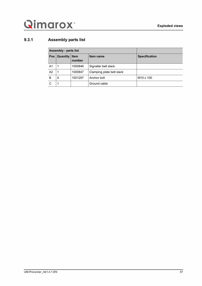
9.3.1 Assembly parts list/i
Assembly - parts list
Pos Quantity Itemnumber
Item name Specification
A1 1 1000846 Signaller belt slack
A2 1 1000847 Clamping plate belt slack
B 4 1001297 Anchor bolt M10 x 100
C 1 Ground cable
Exploded views
58 UM-Prorunner_mk1-4.1-EN
9.4 Labels
A
B
PRORUNNER mk
PRORUNNER mk1(kg)
PRORUNNER mk
mk
PRORUNNER mk

UM-Prorunner_mk1-4.1-EN 59
Exploded views
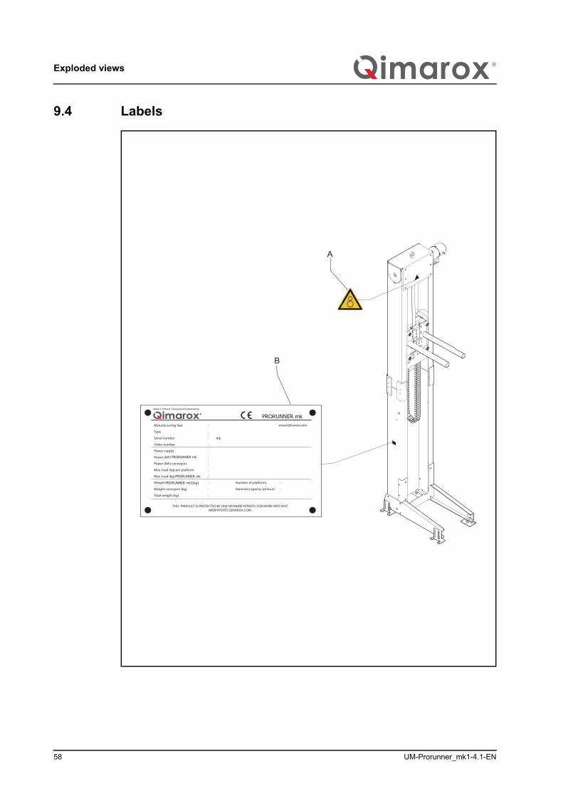
9.4.1 Labels/i
Labels
Pos Quantity Itemnumber
Item name Specification
A 1 1001535 Label jamming
B 1 1000795 Type plate
Electrical drawings
60 UM-Prorunner_mk1-4.1-EN
10 Electrical drawings
10.1 Standard electric drawingshttps://www.qimarox.nl/media/upload/original/56/electrical-drawings-prmk1-v6-0-1515144656.pdf
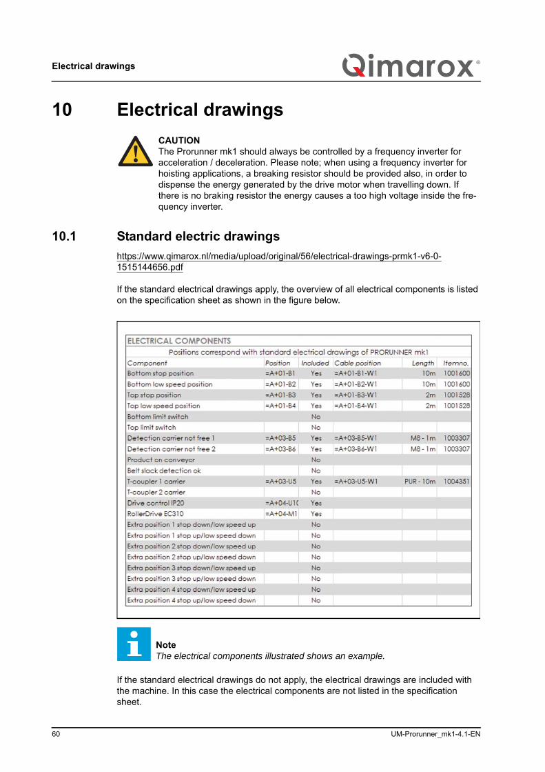
If the standard electrical drawings apply, the overview of all electrical components is listed on the specification sheet as shown in the figure below.
If the standard electrical drawings do not apply, the electrical drawings are included with the machine. In this case the electrical components are not listed in the specification sheet.
CAUTIONThe Prorunner mk1 should always be controlled by a frequency inverter for acceleration / deceleration. Please note; when using a frequency inverter for hoisting applications, a breaking resistor should be provided also, in order to dispense the energy generated by the drive motor when travelling down. If there is no braking resistor the energy causes a too high voltage inside the fre-quency inverter.
NoteThe electrical components illustrated shows an example.
UM-Prorunner_mk1-4.1-EN 61
Electrical drawings
10.2 Drives
10.2.1 Drive type: SEW 3PHConnection main power:http://www.productliften.nl/media/text/240/247/680010306.pdf
Connection TF:http://www.productliften.nl/media/text/240/247/681510306.pdf
Connection BR:http://www.productliften.nl/media/text/240/247/69001006.pdf
Other connection diagrams DR:http://www.productliften.nl/media/text/240/247/9pd0058us.pdf
10.2.2 Drive type: MovimotConnections Movimot:http://www.productliften.nl/media/text/240/247/17000017.pdf
http://www.productliften.nl/media/text/240/247/16742419en.pdf

/i
Nobelstraat 43 3846 CE Harderwijk Tel: +31 341 436 700 Fax: +31 341 436 701 E-mail: [email protected] Internet: www.Qimarox.com