Embed Size (px)
Citation preview

1
E
MERGENC
Y
STOP
USER MANUAL
Heat presses Transmatic TS 2P/3 P / TS 5 P / TS 5 PA
Original Manual in Englisch ! To keep for future purpose !
Stand: 21/07/2016 Version: 01
2
INTRODUCTION
ARTICLE
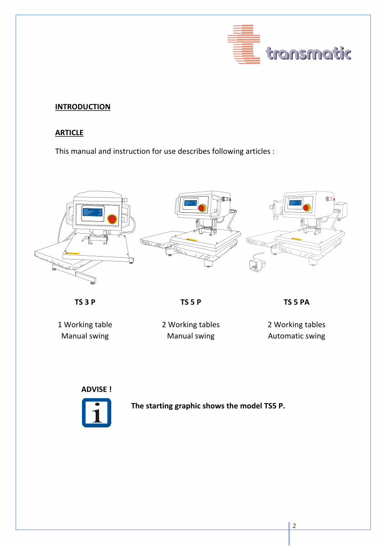
This manual and instruction for use describes following articles :
E
MERGENC
Y
STOP
E
MERGENC
Y
STOP
TS 3 P
1 Working table
Manual swing
TS 5 P
2 Working tables
Manual swing
TS 5 PA
2 Working tables
Automatic swing
ADVISE !
The starting graphic shows the model TS5 P.

3
GENERAL INFORMATION
This user manual must be at all times available to the operators and the service team of the machine.
The owner of this machine must make sure that the operators, service, and maintenance team have available the fault finding chart and that all work is carried out by competent staff. This manual will help you:
to understand the use of the machine
to use the machine properly
to extend the life time of the machine
The change of the power cable has to be effected by qualified or trained persons in order to avoid injury
Please read this manual carefully. It contains important information in order to use the machine safely and efficiently.
The operation of this machine in compliance of the manual will assure :
The safety of the operating personal and the avoidance of working accidents.
Transmatic Srl. assumes no liability of damage or malfunctions resulting from failure to observe this manual
Power cables and pneumatic pipes are to be connected properly in order to avoid tripping hazards.
The machine must be placed on a flat (No slope) surface with sufficient structural strength.
4
WARRANTY AND LIABILITY
The present operating and maintenance manual was written with utmost care. All information and instructions for operations and maintenance is written while taking into account our experience and knowledge in good faith. This operating and maintenance instruction corresponds with text and illustrations from recent technical information. The contents of the manual lay no claims by the purchaser. If you note any omissions and or errors, we ask you in your own interest to inform us about it, for correction.
The time of the warranty of this machine is one year for mechanic and electric parts, 3 years for electronic parts. Consumable parts as PTFE covers, felts and silicone rubber are excluded from the warranty.
Warranty and liability for personal injury are excluded in case of:
• Improper operation and/or maintenance of the machine • Operation of the machine with defective or non-functioning safety and protective devices.
• Operation of the machine with broken or not fully functional parts and assemblies. • Failure to follow the instructions in detail • Unauthorized modifications or changes to the machine • Improper repair • Acts of God or vandalism • Unauthorized changes and modifications on machines and machine systems, in particular to control, mechanical, hydraulic or pneumatic components.
The above will also lead to cancellation of our EG declaration of conformity and the loss of the CE mark.
5
SPECIAL WARNINGS AND SPECIAL INFORMATIONS
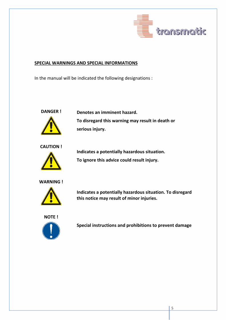
In the manual will be indicated the following designations :
DANGER !
Denotes an imminent hazard.
To disregard this warning may result in death or
serious injury.
CAUTION !
Indicates a potentially hazardous situation.
To ignore this advice could result injury.
WARNING !
Indicates a potentially hazardous situation. To disregard this notice may result of minor injuries.
NOTE !
Special instructions and prohibitions to prevent damage

6
SECURITY – AVOIDING HAZARDS PROPER USE
The heat presses Transmatic TS3P / TS5P / TS5 PA are exclusivly designed to be used to print on textiles as well as subarticles as T-Shirts, Sweaters, Flag fabrics, Mousepad etc. Any other use is considerated improper ! The supplier will not be liable of damages resulting from improper use.The risk lies entirely by the user.
Before using the heat presses Transmatic TS3P/ TS5P/ TS5PA outside the above range of application, the customer service is to be consulted. Anything to the contrary of this eliminates warranty.
The intended use includes the oberservance of the operating and maintenance instructions and the regular service of the machine.
The heat presses have to be used and maintained only by trained persons.
The heat presses have to be used only with original accessories and spare parts.
NOTE !
Wrong use could cause injury or hinderence to:
- body and life
- objects
- efficient use of the machine
7
DANGER SOURCES ACCIDENT PREVENTION
SOURCES OF DANGER
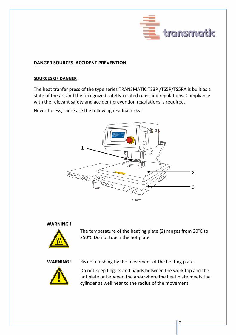
The heat tranfer press of the type series TRANSMATIC TS3P /TS5P/TS5PA is built as a state of the art and the recognized safetly-related rules and regulations. Compliance with the relevant safety and accident prevention regulations is required.
Nevertheless, there are the following residual risks :
E
MERGENC
Y
STOP
WARNING !
The temperature of the heating plate (2) ranges from 20°C to 250°C.Do not touch the hot plate.
WARNING!
Risk of crushing by the movement of the heating plate.
Do not keep fingers and hands between the work top and the hot plate or between the area where the heat plate meets the cylinder as well near to the radius of the movement.
2
3
1

8
SAFETY DEVICES
CAUTION !
Never remove or modify safety devices.
Do not operate the machine if safety devices are not working correctly.
EMERGENCY
STOP BUTTON
E
MERGENC
Y
ST
Pressing the emergency stop button only raises the hot plate. Voltage and compressed air supply is not interrupted. Risk of accident !
PERSONAL PROTECTIVE EQUIPMENT
Not required.
CE-MARK
The heat presses Transmatic TS3P / TS5P/TS5PA has been built in accordance with all relevant EU standards and is fitted with the CE mark.
The attached declaration of conformity loses it‘s validity when the machines altered or changed without our consent.
9
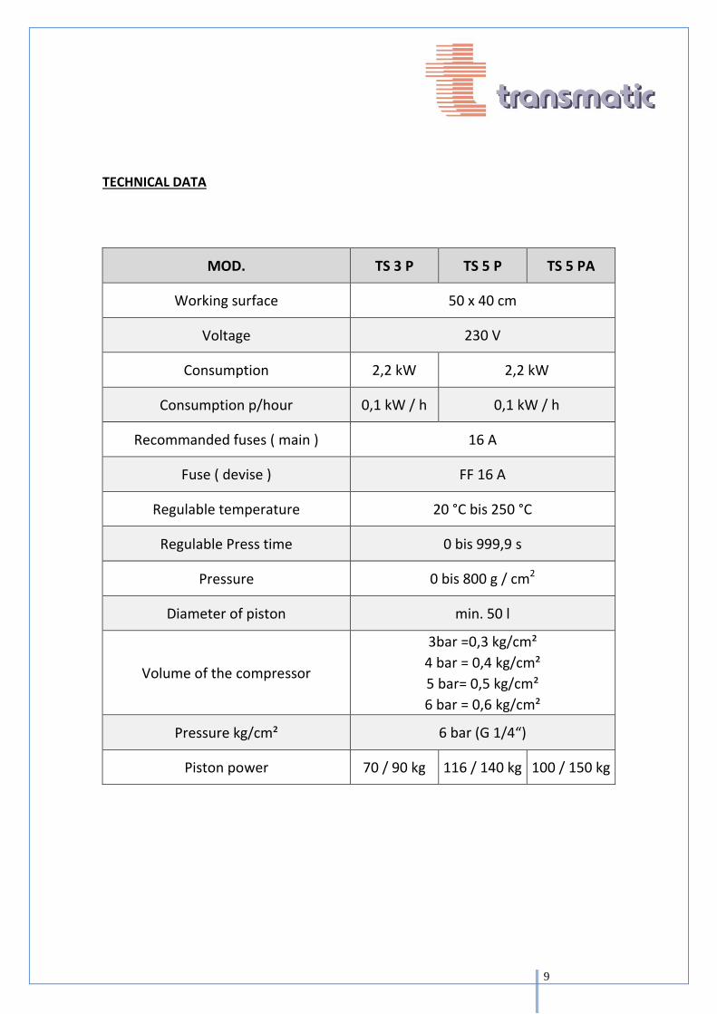
TECHNICAL DATA
MOD. TS 3 P TS 5 P TS 5 PA
Working surface 50 x 40 cm
Voltage 230 V
Consumption 2,2 kW 2,2 kW
Consumption p/hour 0,1 kW / h 0,1 kW / h
Recommanded fuses ( main ) 16 A
Fuse ( devise ) FF 16 A
Regulable temperature 20 °C bis 250 °C
Regulable Press time 0 bis 999,9 s
Pressure 0 bis 800 g / cm2
Diameter of piston min. 50 l
Volume of the compressor
3bar =0,3 kg/cm²
4 bar = 0,4 kg/cm²
5 bar= 0,5 kg/cm²
6 bar = 0,6 kg/cm²
Pressure kg/cm² 6 bar (G 1/4“)
Piston power 70 / 90 kg 116 / 140 kg 100 / 150 kg

10
INSTALLATION
WORKSTATION
Place the heat press on a sturdy work table.
Set up the press with the feet ( 1 ) Make sure that it is resting flat and not wobbling.
WARNING !
The working table has to be aligned and be strong enough to support the weight of the press. The movement of the head of the press may move the machine. It is recommanded to fasten the feet to the table.
INSTALLATION AND ASSEMBLY
Remove the packing.
Check the machine after unpacking and setting on the table. Check to be sure there are no obvious defects.
1

11
ELECTRICAL CONNECTION
Check, that the power switch of the machine is switched off.
Insert the plug into the socket ( 230 V )
WARNIG!
Connect the cable in a manner to avoid tripping hazards
PNEUMATIC CONNECTION
DANGER!
Connection to the pneumatic hose will cause the heat plate to raise up immediately. Risk of Accident !
Connect the hose to the pneumatic air supply ( 1 ) Slide valve to “ ON “ Position
ADVISE: Regulation of the air pressure see capt. 6.4.2
WARNING!
Connect the pneumatic hose and cables in a way to avoid tripping hazards
1 2

12
FEATURES OF THE MACHINE TS3P/TS5P/TS5PA
1. General Switch On/Off 2. Speed regulator ( Regulates the speed of
opening of the plate) 3. Fuse 4. Main Cable 5. Heat plate plug 6. Pressure regulation (In- coming
pressure) 7. Maintenace unit 8. Slide valve 9. Compressed air supply 10. Pressure regulator (Working pressure) 11. Quick release lever of the working plate
Automatic opening
High productivity
Pre-press Funtion
Easy exchangeable underplates
Strong and rugged design for industrial use
5
1 2
3
4
7
10
8
6
9
11

13
TS 3 P
Detail “A”
1. Working plate with Nomex cover
2. Lever to change the top plate
3. Automatic Closing by pressing of 2 buttons
4. 2 Handles
5. Display
6. Emergency Stop
7. Guide
8. Heating plate with PTFE cover
9. Feet
10. Micro switch
9
1 8
2
3
4
5 6
7
“A”
10
14
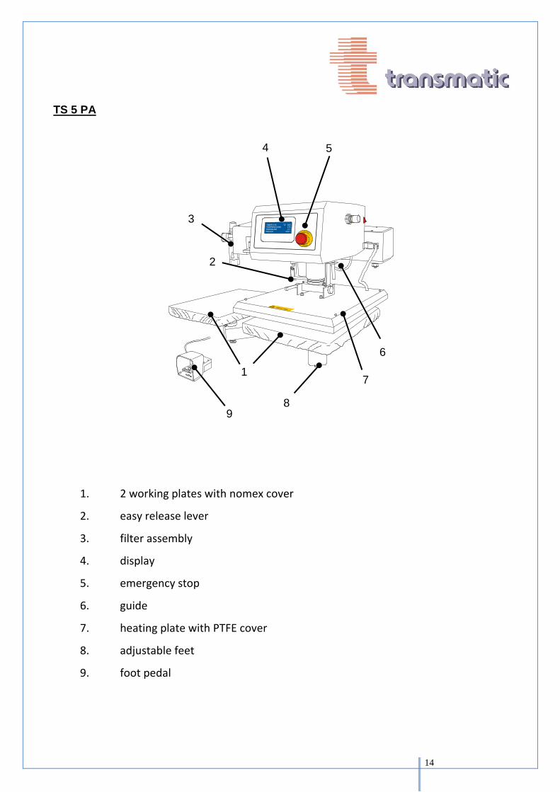
TS 5 PA
E
MERGENC
Y
STOP
1. 2 working plates with nomex cover
2. easy release lever
3. filter assembly
4. display
5. emergency stop
6. guide
7. heating plate with PTFE cover
8. adjustable feet
9. foot pedal
8
1 7
2
4 5
6
9
3

15
START UP
NOTICE !
Electrical Plug must be inserted
Compressed air should be connected
Press must stand firm and level
Place main switcher to position 1.
INSTRUCTION TOUCH SCREEN
Temperature Heating Plate Set Temperature Menu Pressure SETPOINT SETTINGS
Follow the indications of your transfer paper manufacturer. To change temperature setting ,touch box digit the new value and press enter to store. The first value on the display (*) shows you the real temperature on the heating plate, the second value (**) shows the set temperature. The machine is ready to press when both values are the same. Temperature alarm is activated until heating does not reach the set temperature. (*) (**)
Timer
Piece counter
Activated Allarms
1 2A
1 2A

16
SETTING TIMER
To change timer settings press on box , use fingerboard to write in the new value – press enter to store.
RESET PIECE COUNTER
on the main MENU touch this box Touch here to reset the counter PS: It is not possible to reset the historical value.
2 2A
2 2A

17
SUBMENU TOUCH SCREEN Touching MENU you login the submenu
INPUT/OUTPUT PLC
SETTING AND CHANGE OF SETPOINTS PRESET You may create 4 customized presetting’s. Press “ Cycle set “ to activate or change a preset.
Setting and change of setpoints preset
Acustic signal on/off
In/out PLC
Manual pdf
Allows the visual on the exits of the PLC and eventual faults. In case of fault contact TRANSMATIC .

18
1. CHANGE PRESET
- Touch arrow to enter the menu
- Set requested setpoints
2. ACTIVATE PRESET
To activate Preset press on the number of the program
Set 2 °C: Underplaten Heating if machine with this option
Preheating Remember to activate Quantities of timers( see page 16)
Type: Name of Preset Press here to change name of the preset.
- Control on the main menu if the program is activated. - Control that the pressure is the same than The preset ( If the box light yellow – the pressure is >< di 0,3 bar respect of the set value )(see page 19 for change pressure)
Preset pressure
Real pressure

19
E
MERGENC
Y
ST
SETTING QUANTITY OF TIMERS ( ADD PREHEATING) Touch “ Main set “ to increase quantities of the timers. Touch symbol to activate : 1 : timer for the pressing time 2 : timer for the pressing time and timer for the preheating/ironing of the material before printing OPTION : ACTIVATE AUTOMATIC START ( ONLY TS5PA )
1)Attivate WAIT TIMER 2)Select waiting time between one and another print 3)Control , on the main menu If the program is active 4)Once the program is active – press the start pedal - 5)From this moment the machine works automatically
In case of emergency press the emergency stop

20
REGULATION OF THE PRESSURE
OPERATING PRESSURE
Set the operating pressure on the knob ( 1 ) of the maintenance unit. Pull the knob up until the yellow ring is visibile. Set the maximum Pressure. The display on the gauge ( 2 ) should show 5 to 8 bar. Press the knob again untill the yellow ring is no longer visible.
PRESSURE
Regulate the cylinder pressure with the regulator on the opposite side of the machine. Pull out the knob untill you can see the yellow ring.
Turning to the + direction you increase the pressure
Turning to the – direction you decrease the pressure
The pressure can be adjusted between min. 1.5 bar and a maximum of 6 Bar.
After the setting of the value you have to push the controller until the 'yellow ring is no longer visible.
1
2
1

21
ADVISE!
The regulated pressure is indicated on the display only when the heat plate is pressing. Change or correct the value until you reach the desired pressure.
The display reacts a little slow and can change sometimes if the machine stands still.
BACK PRESSURE OPTION
Machines equipped with back pressure: You have to set the desired pressure on the pressure gauge located on the right of the machine (we recommend a minimum pressure of 4 bar) Subsequently pressure has to be set on the pressure gauge on the left side of the machine back pressure (for example 2 bar). At this point the pressure setting on the plate is set on 2 bar effective
The back pressure must be inserted in the case you need to apply transfers on a very high flor or to prevent marks on the material to be printed. We suggest to put the pressure to 0 in the case of using transfers of common use.
SELECT THE SPEED OF THE PISTON
You can regulate the speed of piston on the speed regulator ( 1 ) on the back of the machine.
1

22
CAUTION !
Take care of the temperature of the working plate if you want to change it during the operation.
1. Swing both of the quick- relaese levers und the working plate ( 1 ) for 180°.
2. Withdraw the plate ( if you want to change the silicon rubber for example )
1. When re-installing the countertop make sure the the mounting holes (3) of the working plate are placed correctly to the locking pins of the holder.
2. Swing the quick – release levers once again for 180 ° to the old position. The plate is locked.
3
4
1
1
2

23
MAINTENANCE, CARE AND CLEANING
DAILY AND AS NEEDED
After work, clean the PTFE cover of possible adhesive residue, with a soft and clean cloth.
MONTHLY
Check the PTFE covering the hot plate. If the PTFE cover is torn or damaged it must be replaced.
Check the nomex cover and the silicon rubber on the bottom plate. Change the cover if it is damaged. If the silicon rubber has no indentations or high and low spots, it should also be replaced.
After switching off the pressure and any collected moisture will drain out alone.
2
1
2 1

24
6 MONTHS
Test the effective temperature on the plate using a temperature strip. If the real temperature is lower or higher please increase the temperature on the display accordingly.
YEARLY
Electrical testing in accordance with accident prevention
Check if joints are moving smoothly, oil or grease with ordinary bearing grease.
Grease guide rod ( 1 ) and locking pins with normal grease.
HOW TO CHANGE THE PTFE COVER
If the PTFE cover is damaged it has be be replaced. Switch off the machine and make sure that the heating plate is cold.Unscrew the 4 screws ( 1 ) and you loose the 2 rods holding the teflon sheet. Change the PTFE cover and punch 4 little holes in the PTFE textiles in order to fix again the teflon as before.
ADVICE!
On the 2 rods there are 2 threadend pins which fits into the screws.
1
2
2 1

25
CHANGING THE ACCESSORY
To change out the flat working plate with an cap accessory:
1. Unscrew the Allen screw. ( 2 )
2. Change the plate together with its base.(1)
3. Align the hole oft he punch( 3 ) to the bolt position.
4. Tighten the allen screw very firmly.
2
1
3
26
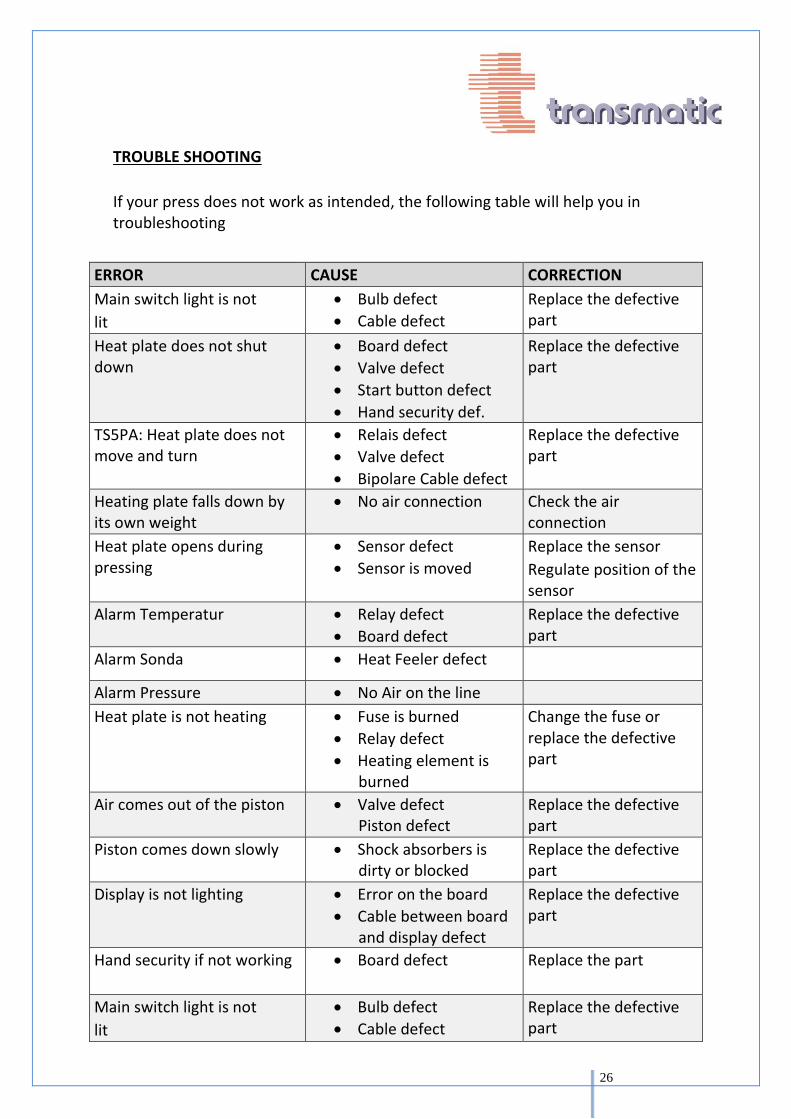
TROUBLE SHOOTING
If your press does not work as intended, the following table will help you in troubleshooting
ERROR CAUSE CORRECTION
Main switch light is not
lit
Bulb defect
Cable defect
Replace the defective part
Heat plate does not shut down
Board defect
Valve defect
Start button defect
Hand security def.
Replace the defective part
TS5PA: Heat plate does not move and turn
Relais defect
Valve defect
Bipolare Cable defect
Replace the defective part
Heating plate falls down by its own weight
No air connection Check the air connection
Heat plate opens during pressing
Sensor defect
Sensor is moved
Replace the sensor
Regulate position of the sensor
Alarm Temperatur Relay defect
Board defect
Replace the defective part
Alarm Sonda Heat Feeler defect
Alarm Pressure No Air on the line
Heat plate is not heating Fuse is burned
Relay defect
Heating element is burned
Change the fuse or replace the defective part
Air comes out of the piston Valve defect Piston defect
Replace the defective part
Piston comes down slowly Shock absorbers is dirty or blocked
Replace the defective part
Display is not lighting Error on the board
Cable between board and display defect
Replace the defective part
Hand security if not working Board defect Replace the part
Main switch light is not
lit
Bulb defect
Cable defect
Replace the defective part
27
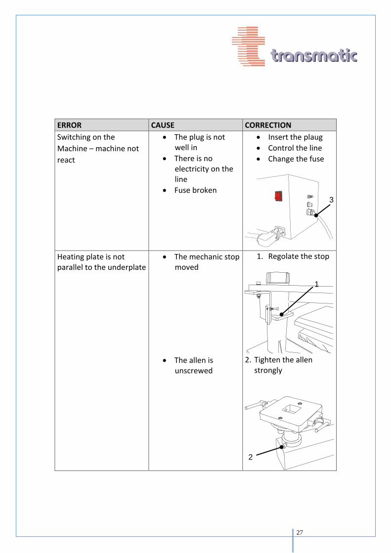
ERROR CAUSE CORRECTION
Switching on the
Machine – machine not
react
The plug is not well in
There is no electricity on the line
Fuse broken
Insert the plaug
Control the line
Change the fuse
Heating plate is not parallel to the underplate
The mechanic stop moved
1. Regolate the stop
The allen is
unscrewed
2. Tighten the allen strongly
1
3
2

28
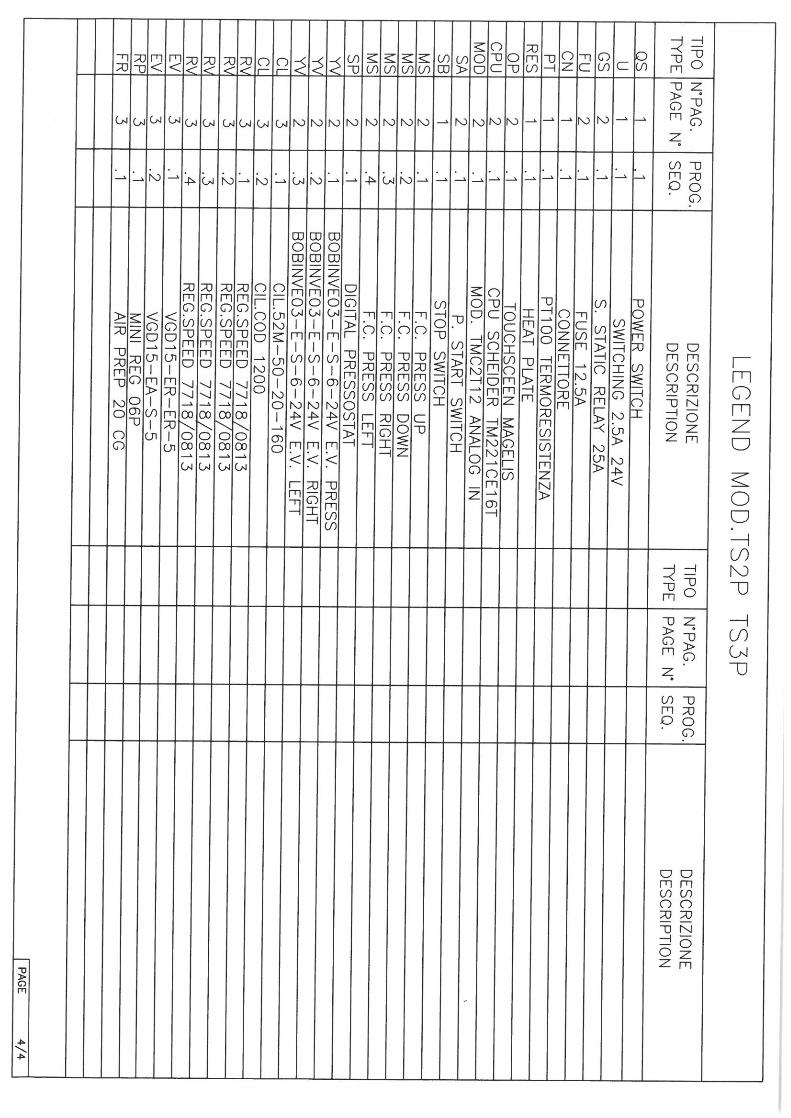
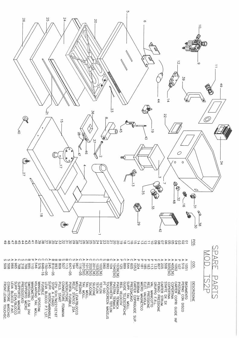
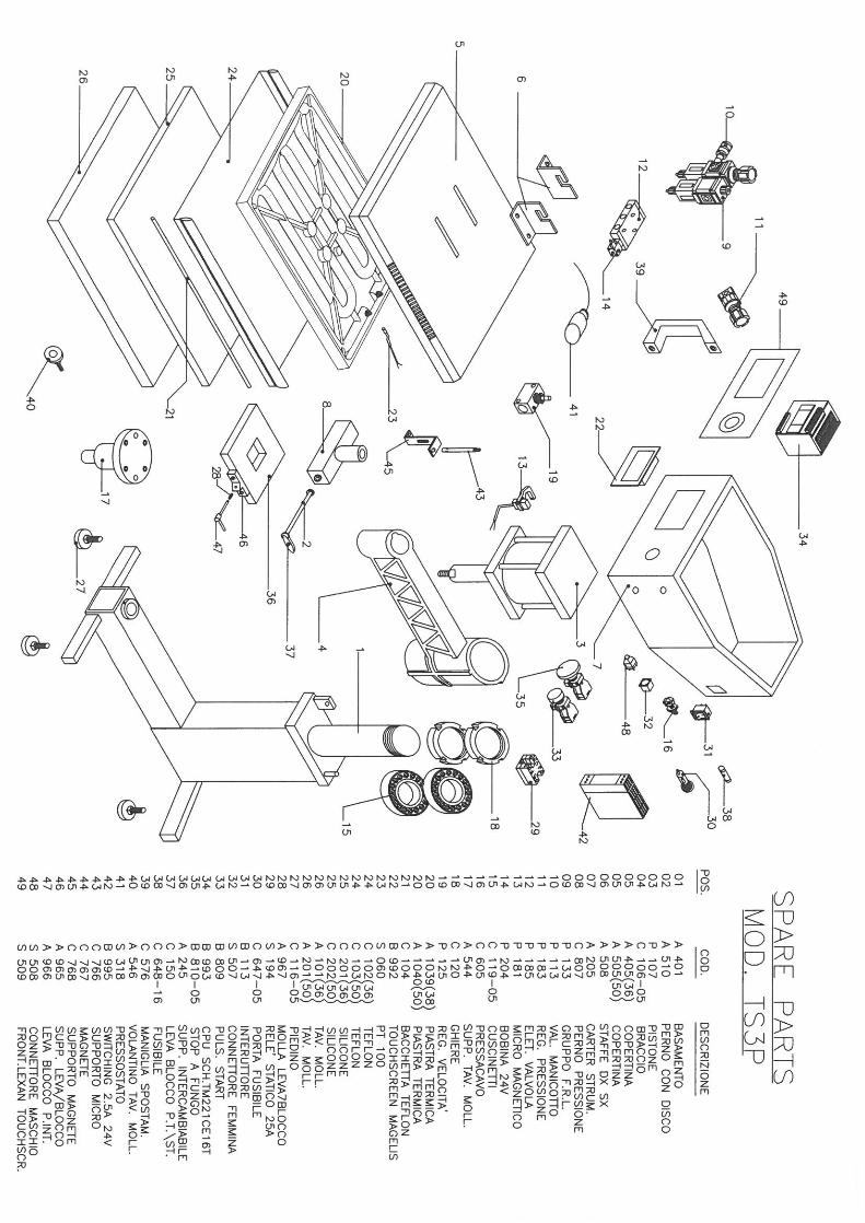
SPARE PARTS
Ordering spare parts or asking for a technical assistance.
ADVISE!
The machine number and the year of construction are always to be comunicated before asking for assistance.
You find the serial number (1 ) on the back of the base.
DISPOSAL
This product may not be released to the normal disposal at the end of it’s life.
Transmatic Srl Via E. Ferrari 9/11/13 20020 Lazzate (MI) Italy Tel +39 02 96329816 / +39 02 96728422 fax
1