Embed Size (px)
Citation preview
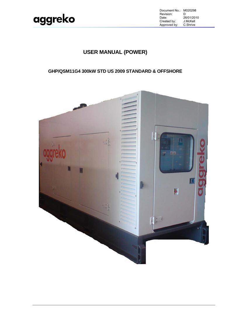
Document No.: M020298 Revision: D Date: 26/01/2010 Created by: J.McKell Approved by: C.Shrive
USER MANUAL (POWER)
GHP/QSM11G4 300kW STD US 2009 STANDARD & OFFSHORE
Document No.: M020298 Revision: D Date: 26/01/2010 Created by: J.McKell Approved by: C.Shrive
- i -
TABLE OF CONTENTS
1.0 SAFETY 1.1. GENERAL INFORMATION.....................................................................................................1 1.2. ELECTRICAL POWER ...........................................................................................................1 1.3. MATERIALS............................................................................................................................1 1.4. OPERATIONAL PRECAUTIONS ...........................................................................................1 1.5. SAFETY LABELS ...................................................................................................................2
2.0 NOISE EMISSION 2.1. NOISE CONTROL PROHIBITED ACTS.................................................................................4 2.2. GENERATOR NOISE EMISSION CONTROL INFORMATION .............................................4
3.0 HANDLING 3.1. LIFTING / HANDLING.............................................................................................................5 3.2. STORAGE / TRANSPORT .....................................................................................................5
4.0 INSTALLATION 4.1. UNPACKING...........................................................................................................................6 4.2. LOCATION OF THE PLANT...................................................................................................6 4.3. COMMISSIONING...................................................................................................................6 4.4. PRIOR TO STARTING............................................................................................................6 4.5. ELECTRICAL CONNECTION.................................................................................................6 4.6. EARTHING..............................................................................................................................6 4.7. REMOTE FUELLING ..............................................................................................................7
5.0 GENERAL DATA 5.1. GENERAL OPERATION.........................................................................................................8 5.2. DESIGN LOAD CAPACITY ....................................................................................................8 5.3. DESIGN TEMPERATURES ....................................................................................................8 5.4. CANOPY & BASE FRAME.....................................................................................................8 5.5. DIESEL ENGINE.....................................................................................................................9 5.6. ENGINE LUBRICATION SYSTEM .........................................................................................9 5.7. ENGINE COOLING SYSTEM .................................................................................................9 5.8. ENGINE FUEL SYSTEM.........................................................................................................9 5.9. EXHAUST SYSTEM..............................................................................................................10 5.10. ENGINE CONTROL SYSTEM ..............................................................................................10 5.11. GENERATOR........................................................................................................................10 5.12. MAIN CIRCUIT BREAKER ...................................................................................................10
6.0 OPERATING INSTRUCTIONS
Document No.: M020298 Revision: D Date: 26/01/2010 Created by: J.McKell Approved by: C.Shrive
- ii -
6.1. OPERATING CONTROLS AND INSTRUMENTS................................................................12 6.2. OPERATING PROCEDURE .................................................................................................16 6.3. MODES OF OPERATION .....................................................................................................17 6.4. ALARM FUNCTIONS............................................................................................................19 6.5. CHANGING PARAMETERS.................................................................................................20
7.0 MAINTENANCE 7.1. GENERAL .............................................................................................................................23 7.2. MAINTENANCE SCHEDULE ...............................................................................................24 7.3. DAILY MAINTENANCE ........................................................................................................25 7.4. WEEKLY MAINTENANCE....................................................................................................26
8.0 LUBRICATION 8.1. GENERAL INFORMATION...................................................................................................27 8.2. GENERATOR OIL CHANGE ................................................................................................27 8.3. OIL SPECIFICATION............................................................................................................27
9.0 TROUBLE SHOOTING 9.1. INTRODUCTION ...................................................................................................................28 9.2. ACTION PLAN ......................................................................................................................28 9.3. TROUBLE SHOOTING CHART ...........................................................................................29
APPENDIX A: Material Safety Data Sheets APPENDIX B: Equipment Data Sheet Document No. Rev. G080337.1 to 3 A
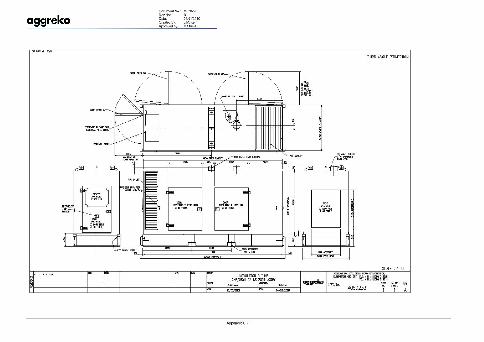
APPENDIX C: Installation Arrangement Drawing No. Rev. A050233.1 A
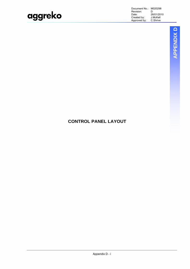
APPENDIX D: Control Panel Layout Drawing No. Rev. D210683.1 A
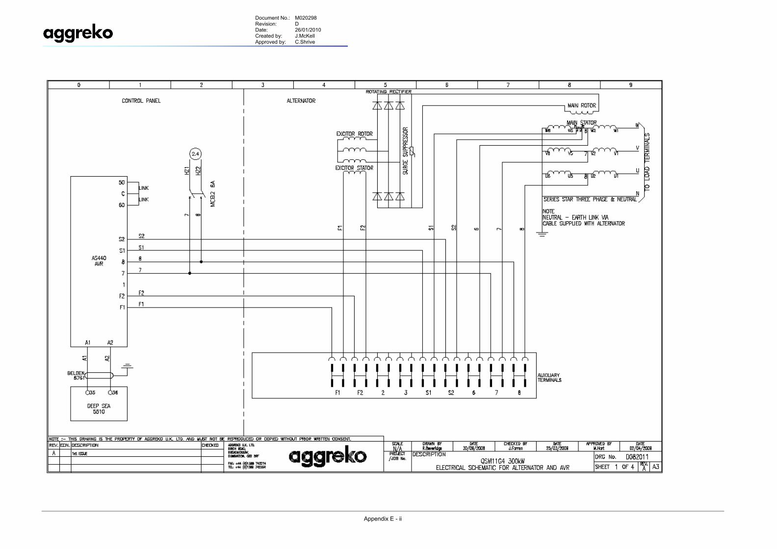
APPENDIX E: Electrical Schematic for Alternator & AVR Type AS440 Drawing No. Rev. D082011.1 A
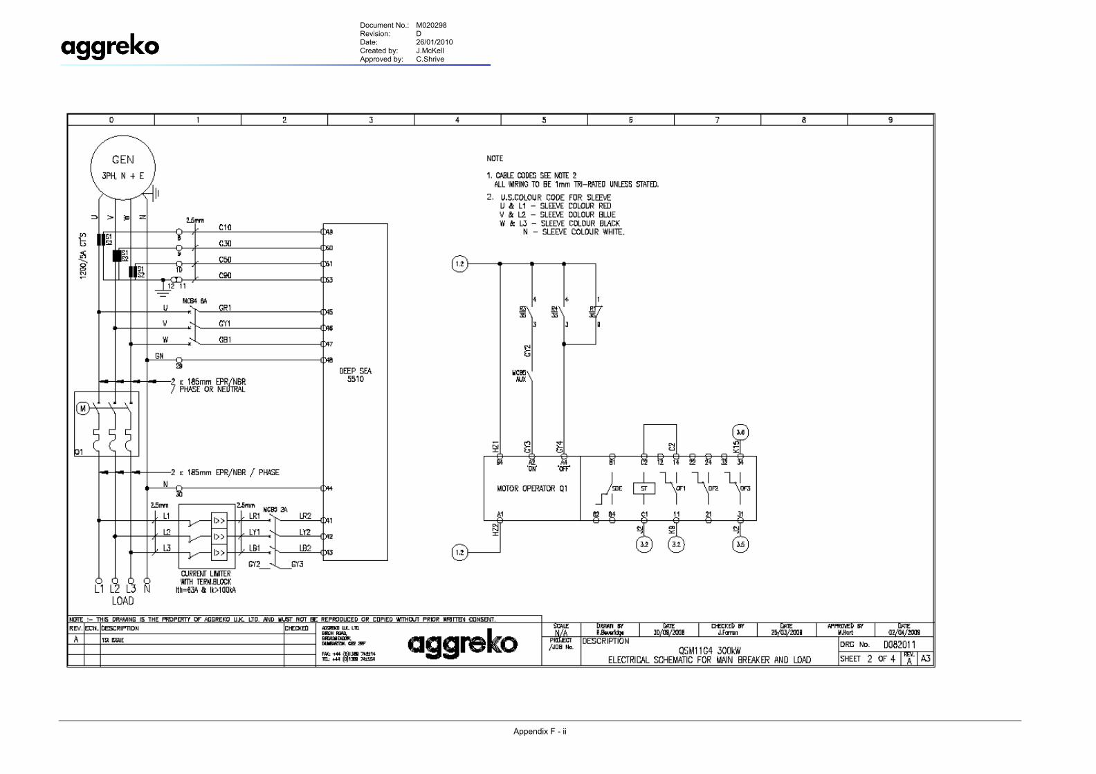
APPENDIX F: Electrical Schematic for Main Break & Load Drawing No. Rev. D082011.2 A
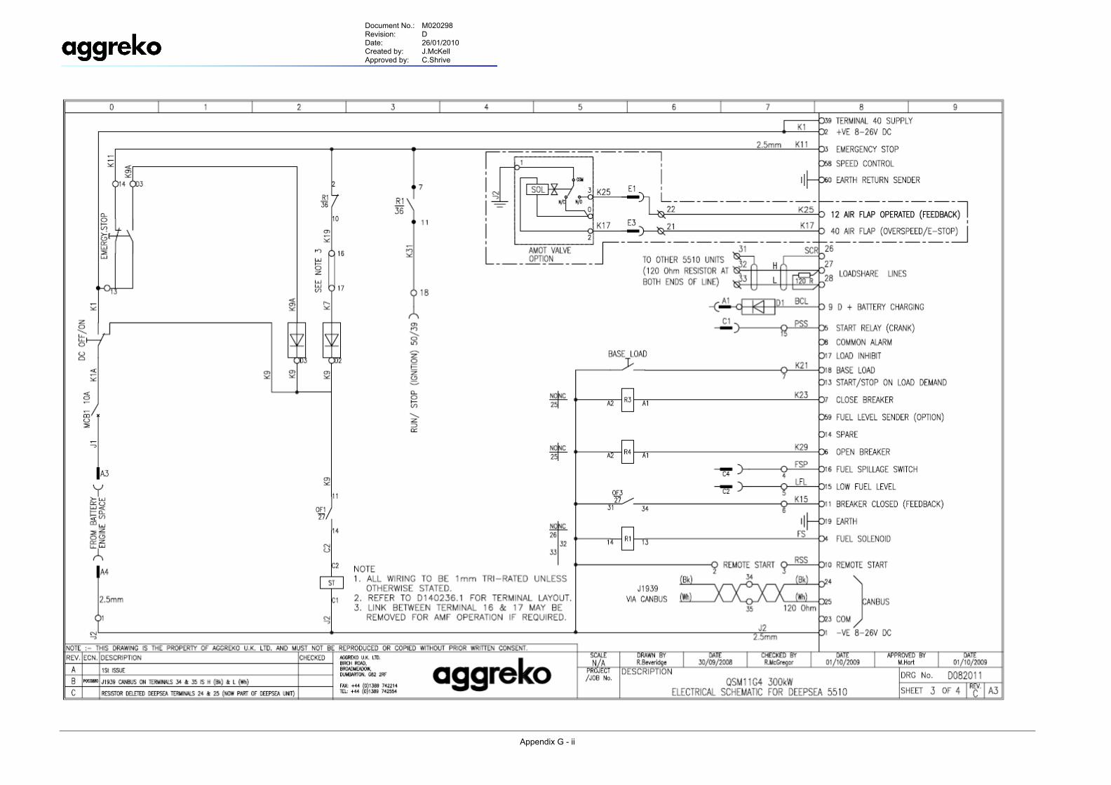
APPENDIX G: Electrical Schematic for Deep Sea 5510 Drawing No. Rev. D082011.3 C
APPENDIX H: Electrical Schematic for Engine & Cummins ECM876
Document No.: M020298 Revision: D Date: 26/01/2010 Created by: J.McKell Approved by: C.Shrive
- iii -
Drawing No. Rev. D082011.4 B
APPENDIX J: Livery Layout Drawing No. Rev.
D200207.1 A
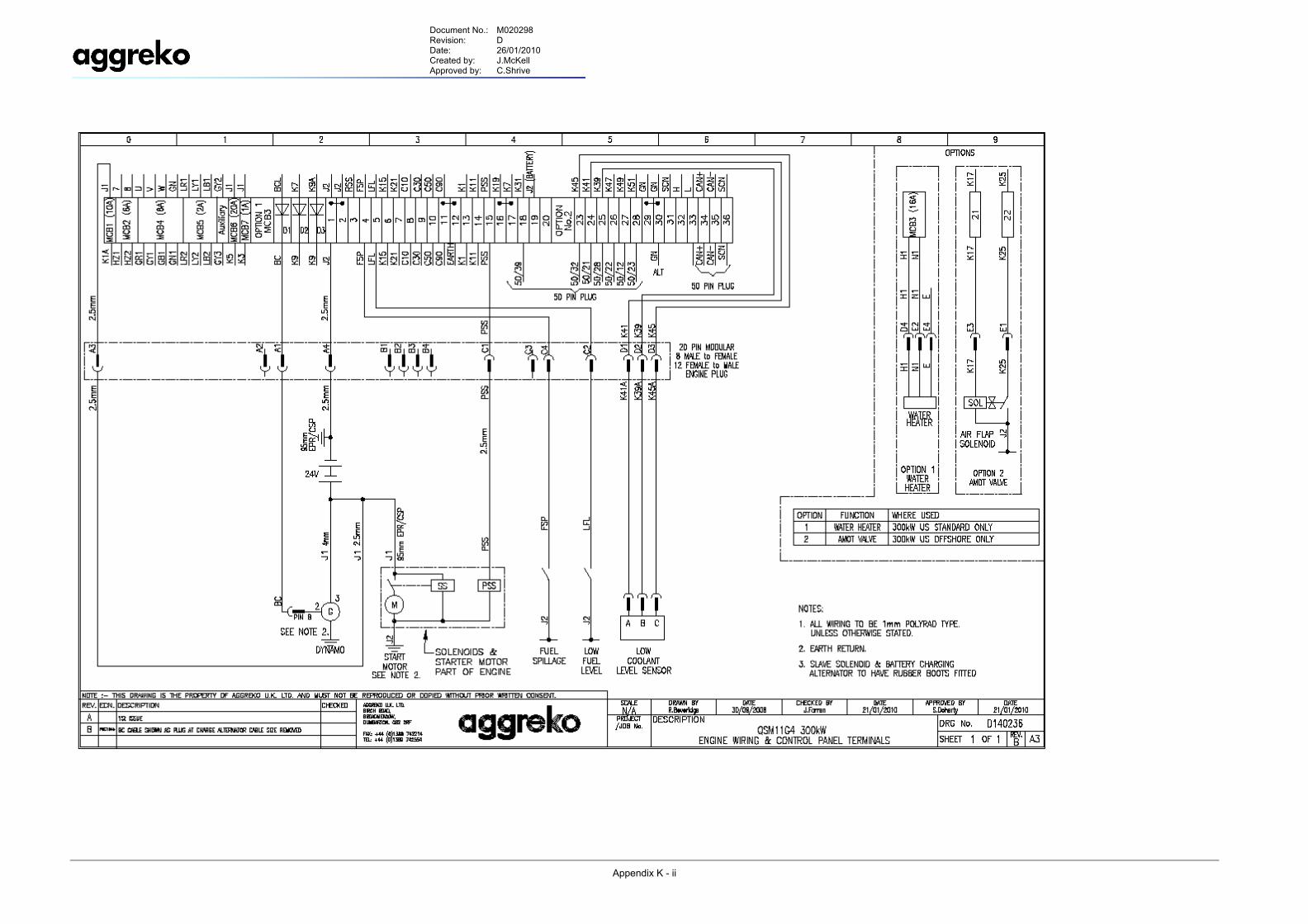
APPENDIX K: Engine Wiring & Control Panel Terminals Drawing No. Rev.
D140236.1 B
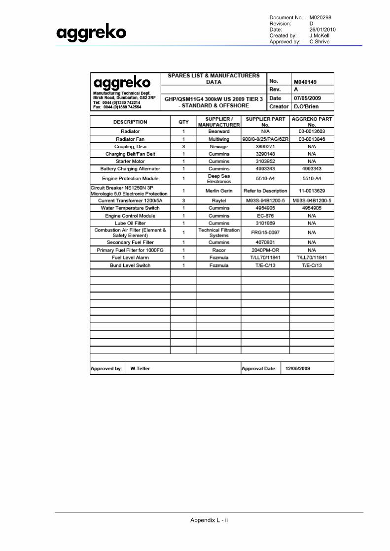
APPENDIX L: Spares List & Manufacturers Component Data Document No. Rev. M040149 A
APPENDIX M: Lifting Beam Certificate – 14700842/001 APPENDIX N: DNV Spark Arrestor Certificate – M10651 APPENDIX P: International Contact Information
Document No.: M020298 Revision: D Date: 26/01/2010 Created by: J.McKell Approved by: C.Shrive
- 1 -
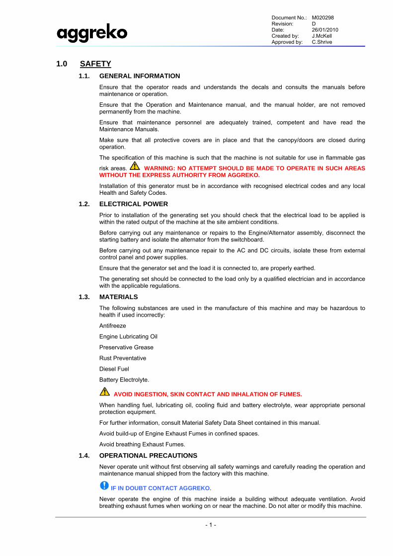
1.0 SAFETY 1.1. GENERAL INFORMATION
Ensure that the operator reads and understands the decals and consults the manuals before maintenance or operation.
Ensure that the Operation and Maintenance manual, and the manual holder, are not removed permanently from the machine.
Ensure that maintenance personnel are adequately trained, competent and have read the Maintenance Manuals.
Make sure that all protective covers are in place and that the canopy/doors are closed during operation.
The specification of this machine is such that the machine is not suitable for use in flammable gas
risk areas. WARNING: NO ATTEMPT SHOULD BE MADE TO OPERATE IN SUCH AREAS WITHOUT THE EXPRESS AUTHORITY FROM AGGREKO.
Installation of this generator must be in accordance with recognised electrical codes and any local Health and Safety Codes.
1.2. ELECTRICAL POWER Prior to installation of the generating set you should check that the electrical load to be applied is within the rated output of the machine at the site ambient conditions.
Before carrying out any maintenance or repairs to the Engine/Alternator assembly, disconnect the starting battery and isolate the alternator from the switchboard.
Before carrying out any maintenance repair to the AC and DC circuits, isolate these from external control panel and power supplies.
Ensure that the generator set and the load it is connected to, are properly earthed.
The generating set should be connected to the load only by a qualified electrician and in accordance with the applicable regulations.
1.3. MATERIALS The following substances are used in the manufacture of this machine and may be hazardous to health if used incorrectly:
Antifreeze
Engine Lubricating Oil
Preservative Grease
Rust Preventative
Diesel Fuel
Battery Electrolyte.
AVOID INGESTION, SKIN CONTACT AND INHALATION OF FUMES.
When handling fuel, lubricating oil, cooling fluid and battery electrolyte, wear appropriate personal protection equipment.
For further information, consult Material Safety Data Sheet contained in this manual.
Avoid build-up of Engine Exhaust Fumes in confined spaces.
Avoid breathing Exhaust Fumes.
1.4. OPERATIONAL PRECAUTIONS Never operate unit without first observing all safety warnings and carefully reading the operation and maintenance manual shipped from the factory with this machine.
IF IN DOUBT CONTACT AGGREKO.
Never operate the engine of this machine inside a building without adequate ventilation. Avoid breathing exhaust fumes when working on or near the machine. Do not alter or modify this machine.
Document No.: M020298 Revision: D Date: 26/01/2010 Created by: J.McKell Approved by: C.Shrive
- 2 -
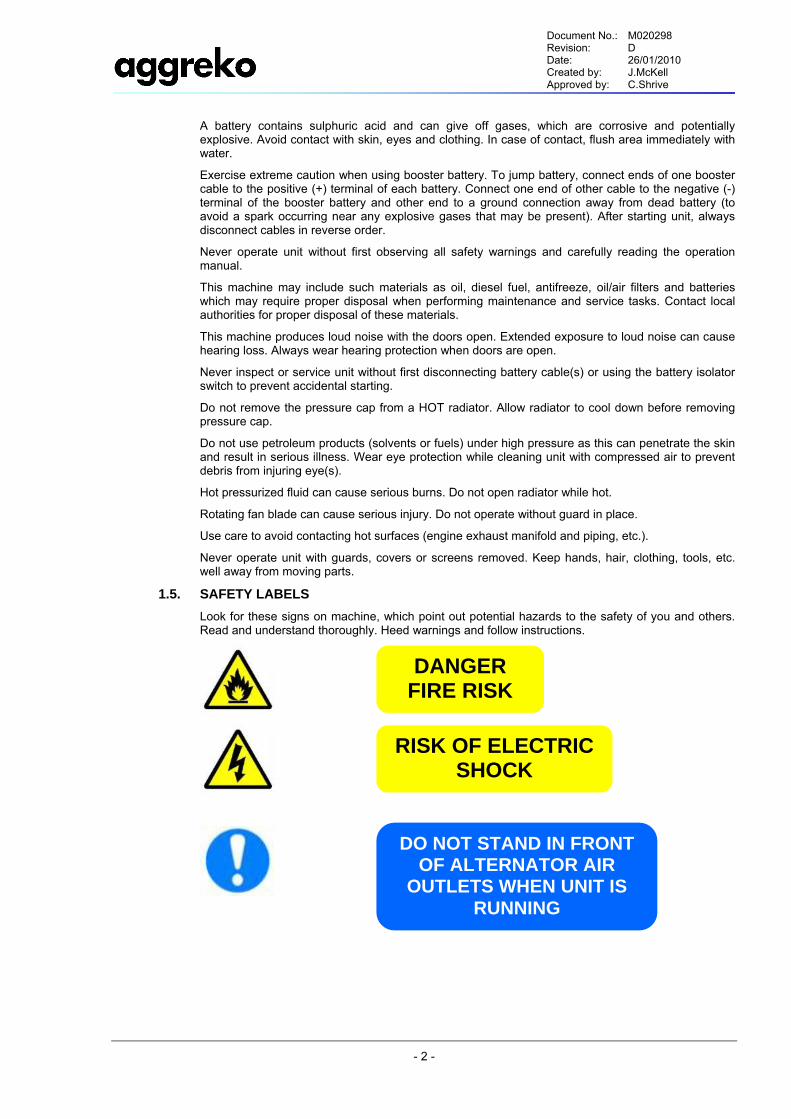
DANGER FIRE RISK
DO NOT STAND IN FRONT OF ALTERNATOR AIR
OUTLETS WHEN UNIT IS RUNNING
RISK OF ELECTRIC SHOCK
A battery contains sulphuric acid and can give off gases, which are corrosive and potentially explosive. Avoid contact with skin, eyes and clothing. In case of contact, flush area immediately with water.
Exercise extreme caution when using booster battery. To jump battery, connect ends of one booster cable to the positive (+) terminal of each battery. Connect one end of other cable to the negative (-) terminal of the booster battery and other end to a ground connection away from dead battery (to avoid a spark occurring near any explosive gases that may be present). After starting unit, always disconnect cables in reverse order.
Never operate unit without first observing all safety warnings and carefully reading the operation manual.
This machine may include such materials as oil, diesel fuel, antifreeze, oil/air filters and batteries which may require proper disposal when performing maintenance and service tasks. Contact local authorities for proper disposal of these materials.
This machine produces loud noise with the doors open. Extended exposure to loud noise can cause hearing loss. Always wear hearing protection when doors are open.
Never inspect or service unit without first disconnecting battery cable(s) or using the battery isolator switch to prevent accidental starting.
Do not remove the pressure cap from a HOT radiator. Allow radiator to cool down before removing pressure cap.
Do not use petroleum products (solvents or fuels) under high pressure as this can penetrate the skin and result in serious illness. Wear eye protection while cleaning unit with compressed air to prevent debris from injuring eye(s).
Hot pressurized fluid can cause serious burns. Do not open radiator while hot.
Rotating fan blade can cause serious injury. Do not operate without guard in place.
Use care to avoid contacting hot surfaces (engine exhaust manifold and piping, etc.).
Never operate unit with guards, covers or screens removed. Keep hands, hair, clothing, tools, etc. well away from moving parts.
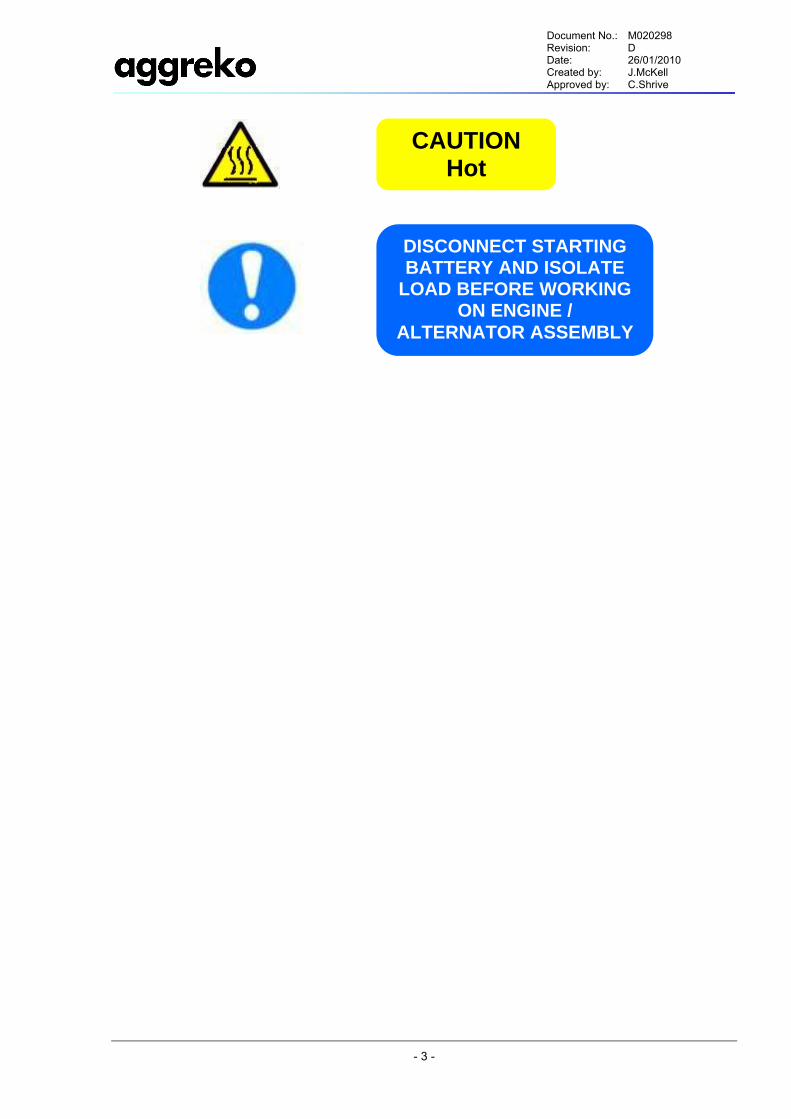
1.5. SAFETY LABELS Look for these signs on machine, which point out potential hazards to the safety of you and others. Read and understand thoroughly. Heed warnings and follow instructions.
Document No.: M020298 Revision: D Date: 26/01/2010 Created by: J.McKell Approved by: C.Shrive
- 3 -
DISCONNECT STARTING BATTERY AND ISOLATE
LOAD BEFORE WORKING ON ENGINE /
ALTERNATOR ASSEMBLY
CAUTION Hot
Document No.: M020298 Revision: D Date: 26/01/2010 Created by: J.McKell Approved by: C.Shrive
- 4 -
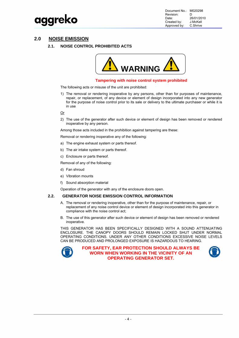
2.0 NOISE EMISSION 2.1. NOISE CONTROL PROHIBITED ACTS
Tampering with noise control system prohibited The following acts or misuse of the unit are prohibited:
1) The removal or rendering inoperative by any persons, other than for purposes of maintenance, repair, or replacement, of any device or element of design incorporated into any new generator for the purpose of noise control prior to its sale or delivery to the ultimate purchaser or while it is in use
Or
2) The use of the generator after such device or element of design has been removed or rendered inoperative by any person.
Among those acts included in the prohibition against tampering are these:
Removal or rendering inoperative any of the following:
a) The engine exhaust system or parts thereof.
b) The air intake system or parts thereof.
c) Enclosure or parts thereof.
Removal of any of the following:
d) Fan shroud
e) Vibration mounts
f) Sound absorption material
Operation of the generator with any of the enclosure doors open.
2.2. GENERATOR NOISE EMISSION CONTROL INFORMATION A. The removal or rendering inoperative, other than for the purpose of maintenance, repair, or
replacement of any noise control device or element of design incorporated into this generator in compliance with the noise control act;
B. The use of this generator after such device or element of design has been removed or rendered inoperative.
THIS GENERATOR HAS BEEN SPECIFICALLY DESIGNED WITH A SOUND ATTENUATING ENCLOSURE. THE CANOPY DOORS SHOULD REMAIN LOCKED SHUT UNDER NORMAL OPERATING CONDITIONS. UNDER ANY OTHER CONDITIONS EXCESSIVE NOISE LEVELS CAN BE PRODUCED AND PROLONGED EXPOSURE IS HAZARDOUS TO HEARING.
FOR SAFETY, EAR PROTECTION SHOULD ALWAYS BE WORN WHEN WORKING IN THE VICINITY OF AN
OPERATING GENERATOR SET.
WARNING
Document No.: M020298 Revision: D Date: 26/01/2010 Created by: J.McKell Approved by: C.Shrive
- 5 -
3.0 HANDLING 3.1. LIFTING / HANDLING
The generator set includes 1 lifting beam and forklift pockets. There is the option for a two-point lift configuration suitable for offshore service.
All lifting and handling equipment must be adequately rated for applicable weights.
During all lifting and handling operations the following weights must be considered.
Complete Package Max. Fuel 6690 kgs (14748 lbs)
Complete Package Without Fuel 5800 kgs (12787 lbs)
Bolt on steel buffers are located at the front and rear of the base to protect the body of the generator.
Where 2 point lifting is provided, ensure that the correct length of strap / wire rope is used on each lifting beam to ensure a level lift. Also ensure that the included angle does not exceed 90°.
CAUTION: THE GENERATOR SET SHOULD NOT BE LIFTED OR DRAGGED BY THE END BUFFERS.
3.2. STORAGE / TRANSPORT Carry out the following points before transporting the generator or preparing the generator for storage.
Empty the fuel tank (in case of overseas transport).
Disconnect the battery terminals (in case of overseas transport).
Close all fuel valves.
Seal the remote fuel connection with a blind stop.
Ensure that the radiator cap is fitted securely and the exhaust rain cap is closed.
Close all doors.
All units are to be loaded flat onto transport and properly secured.
Document No.: M020298 Revision: D Date: 26/01/2010 Created by: J.McKell Approved by: C.Shrive
- 6 -
4.0 INSTALLATION 4.1. UNPACKING
Ensure that the correct fork lift truck slots or marked lifting / tie down points are used whenever the machine is lifted or transported.
4.2. LOCATION OF THE PLANT The generator can be installed on any solid, flat and level surface capable of supporting the full operating load of the package. A dry, well-ventilated area where the atmosphere is as clean as possible is recommended. Ensure that the machine is positioned securely and on a stable foundation.
CAUTION: A minimum of 1 metre (3 ft) all round the generator is recommended. Hot air will exit from the roof outlet. It is important that this hot air does not re-circulate to the package inlet.
The generator must be allowed sufficient space all round and above, to enable the effective removal of the cooling air which, in turn, will reduce the risk of re–circulating the cooling air back through the generator. Adequate clearance needs to be allowed around and above the machine to permit safe access for specified maintenance tasks. Hard surfaces may reflect noise with an apparent increase in the decibel level. It is recommended that provision be made for lifting heavy components during major overhaul.
NOTE: When operating at elevated altitude please refer to engine manufacturer’s guidelines for power deration.
4.3. COMMISSIONING Upon receipt of the unit, and prior to putting it into service, it is important to adhere strictly to the instructions given below in section 4.4 PRIOR TO STARTING.
Ensure all persons concerned are suitably competent with generator installations.
Ensure that the operator reads and understands the decals and consults the manuals before maintenance or operation.
Ensure that the position of the emergency stop device is known and recognised by its markings. Ensure that it is functioning correctly and that the method of operation is known.
4.4. PRIOR TO STARTING Ensure that the unit is clean, free from debris and fluids. All connections, joints, seals must be correctly fitted and tightened. All filters, louvers and air inlets are free and open.
Ensure that there is a safe working procedure which has been issued by supervisory personnel, and that all persons concerned with the operation of the generator understand it.
Ensure that the safety procedure to be applied is based on the appropriate national and local regulations.
Ensure that the safety procedure is followed at all times.
4.5. ELECTRICAL CONNECTION A suitably trained electrician should carry out all electrical connections.
Ensure the generator main isolator is off and that the power cables are in good condition.
Ensure that the phases are correct after the cables have been connected.
Ensure all safety covers are back in place after electrical connection is complete.
4.6. EARTHING An external earthing boss is fitted onto the base frame. This allows a dedicated earthing connection if required.
Document No.: M020298 Revision: D Date: 26/01/2010 Created by: J.McKell Approved by: C.Shrive
- 7 -
4.7. REMOTE FUELLING An external fuel tank supply can be connected to the generator set. The connections required on the remote side are:
One ½” Female Connector (supply)
One ½” Male Connector (Return)
There is an access hole in the base frame to allow access to the internal fuel connections.
Move the fuel change over valve lever to the external fuel position as indicated on the label.
Document No.: M020298 Revision: D Date: 26/01/2010 Created by: J.McKell Approved by: C.Shrive
- 8 -
5.0 GENERAL DATA NOTE: Each generator of this type is uniquely identified by a Plant Number and Serial Number indicated on the identification plate affixed to the outside of the control panel. This information is required when ordering spare parts. Major component serial numbers are contained within the manual.
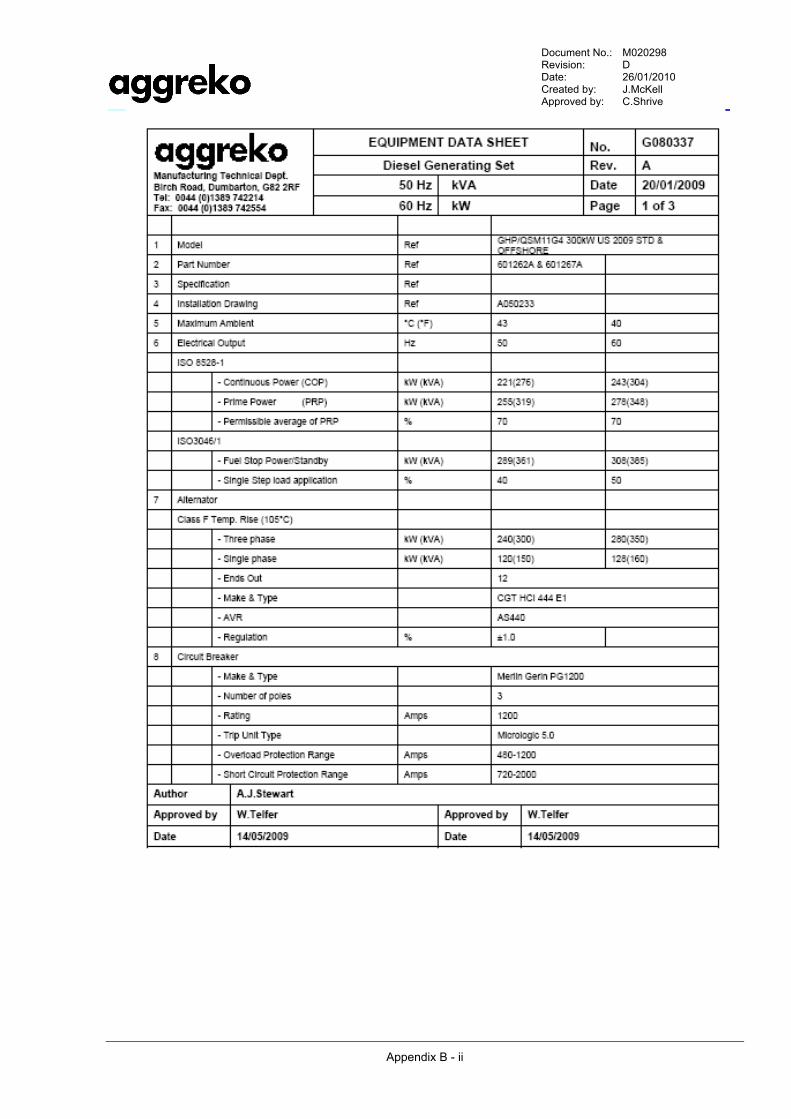
The technical data defining the generator and the limits on its operating environment are tabulated in the Equipment Data Sheet. A copy of the Equipment Data Sheet has been included in the manual.
In order to assist in the operation and maintenance of the generator, a full set of electrical and installation drawings has been included in the manual.
5.1. GENERAL OPERATION The generator is a diesel engine driven alternator with control electronics, mounted on a bedplate with internal fuel tank. The standard package is composed of the following:
Alternator and engine assembly
Pressurised oil system
Automated control system
Instrumentation
Safety provisions
Engine cooler pack
Spark arrestor / Silencer
Internal fuel tank
The engine and alternator are integrally mounted. This assembly is isolated from the base by rubber isolation mounts.
5.2. DESIGN LOAD CAPACITY The GHP/QSM11G4 (300kW) generator set can be run up to a maximum of 243 kW at continuous power rating (60Hz).
5.3. DESIGN TEMPERATURES The GHP/QSM11G4 (300kW) generator set can operate through an ambient temperature range of:
-10°C (14°F) to 40°C (104°F)
5.4. CANOPY & BASE FRAME The overall dimensions for the generator set are 4640 X 1500 X 2575 mm.
The canopy is manufactured from welded Zintec and has access to the inside of the generator through lockable doors.
The base frame has 120% capacity of the fuel tank to prevent fuel leaking out of the generator set in the event of a fuel leakage inside the generator. A level switch is fitted inside the bund for spillage indication. This will shut down the engine when activated.
Document No.: M020298 Revision: D Date: 26/01/2010 Created by: J.McKell Approved by: C.Shrive
- 9 -
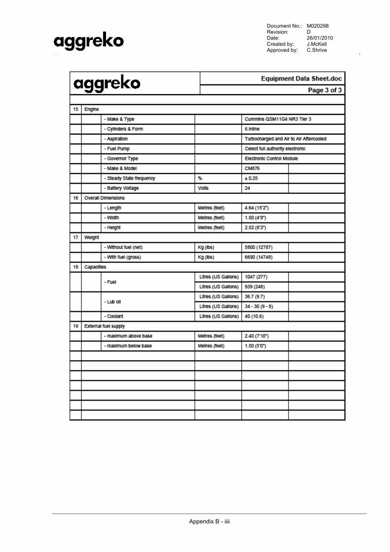
5.5. DIESEL ENGINE The generator set uses a Cummins QSM11G4 diesel engine, which is capable for either 50 Hz or 60 Hz. Details of the engine are outlined below.
Type: Four Stroke, 6 Cylinder In-line, Water Cooled
Model: Cummins QSM11G4
RPM: 1500 / 1800
Nominal Engine Output @ 1800rpm: 278 kW @ Prime Power
Governor: CM876 Electronic
Starting System: 24V Battery System
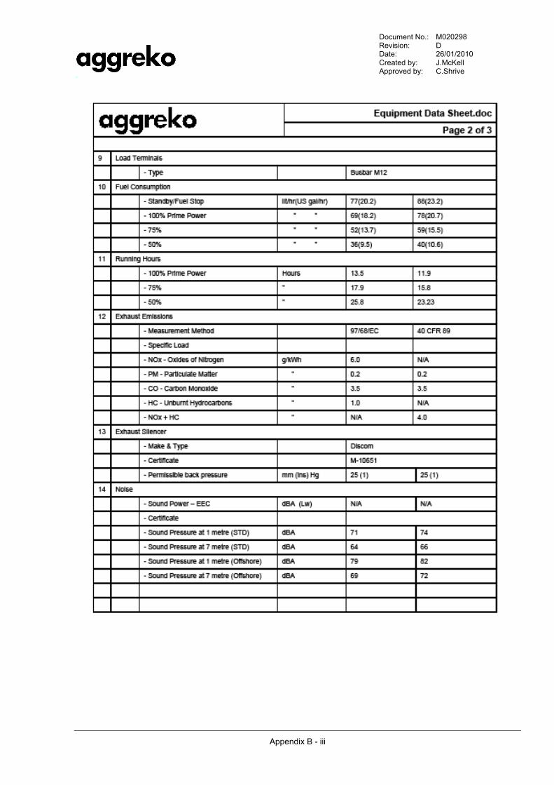
Fuel Consumption @ Continuous 1800rpm: 20.7 US gal/Hr @ 100% Prime Power
5.6. ENGINE LUBRICATION SYSTEM The engine oil lubrication system includes pump, strainer and sump all fitted internally within the engine block. Oil filtration is fitted to the side of the engine block for ease of access and maintenance.
Total Oil Capacity: 9.7 US gal
The Lube oil specification is as per API/ASTM/SAE/CD (equivalent to series MIL-L-415993). Recommended oils are Castrol Tection T 15W-40 (previously called RX Super Plus), Shell Rimula 15W 40.
The sump can be drained using the K1 pump via a Ball valve.
Refer to manufacturers data for all filter information.
5.7. ENGINE COOLING SYSTEM The engine cooling consists of a pump, thermostat, heater and radiator assembly.
Cooling fluid is from the radiator, through the pump, which is belt driven from the engine pulley. The thermostat controls the flow to the radiator. The radiator assembly is mounted at the front of the engine, with the fan mounted on the front of the pump.
Cooling air enters the generator through the canopy end louvers and noise attenuation baffles. This air then passes into the canopy space then across the radiator assembly.
The heated air from the radiator exits through the roof of the package.
The coolant is factory filled with Valvoline HD Extended Life RTU coolant, providing protection to –37°C. Please consult Aggreko if filling is required.
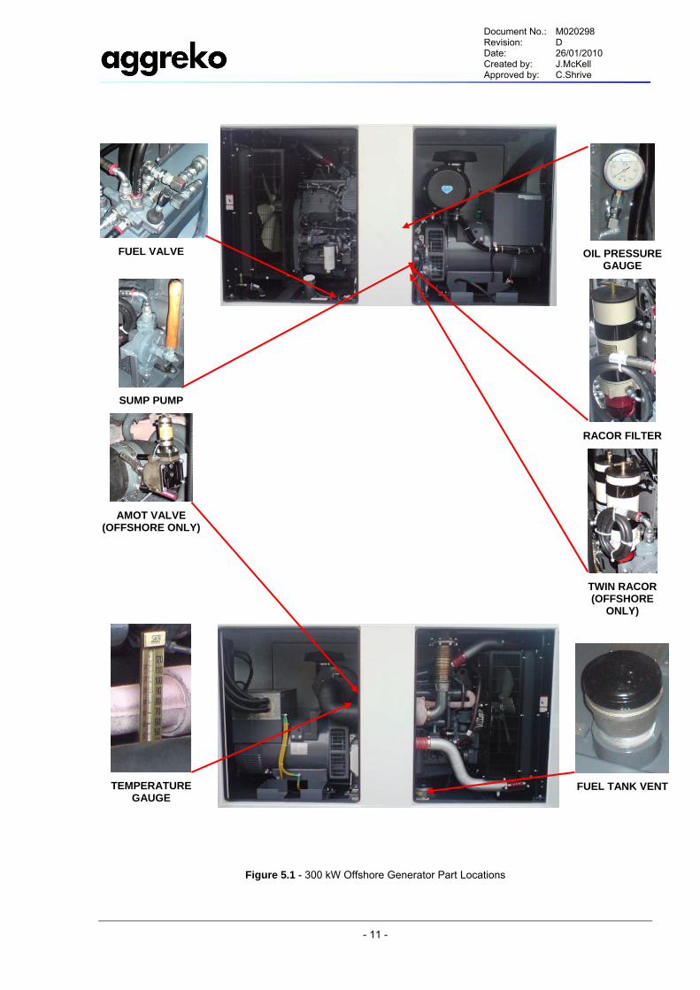
5.8. ENGINE FUEL SYSTEM The engine fuel system consists of an internal fuel tank, Racor filter (see Figure 5.1), fuel pump, injection pump, nozzles and supply selection valve.
Fuel can be taken from either an external or the internal fuel tank. A manual selection valve is used to select the fuel supply direction. Fuel is then pumped through the Racor filter to the fine fuel filters and then passed to the injectors and then to the injection nozzles.
The internal fuel tank has a useable fuel capacity of 248 US gal. Low warning and low shut-off sensors are fitted in the internal fuel tank. A fuel level mechanical gauge is also fitted in the internal tank. The fuel tank fill point is internal. There are 2 cleaning ports on the fuel tank that are all accessible through the canopy doors.
External fuel supply can be connected to the package using the quick release connections at the side of the baseframe (see Figure 5.1). Internal supply and return fittings/valves must be re-configured to ensure that the engine fuel is not drawn from the onboard supply.
The use of ASTM No. 2D fuel is recommended for optimum engine performance. At operating temperatures below 0°C, acceptable performance can be obtained using blends of No. 1 and No. 2D. The use of lighter fuels can reduce economy. The viscosity of fuels must be kept above 1.3 cSt to provide adequate lubrication.
Refer to manufacturers data for all filter information.
Document No.: M020298 Revision: D Date: 26/01/2010 Created by: J.McKell Approved by: C.Shrive
- 10 -
5.9. EXHAUST SYSTEM The exhaust system consists of the exhaust piping, exhaust silencer complete with spark arrestor and rain cap assembly. The exhaust gases exit the engine and are passed through the exhaust piping and exhaust silencer, out the top of the canopy through the rain cap assembly. Insulation is fitted to the exhaust piping and silencer to prevent user contact with high temperature surfaces.
Manufacturer: Discom
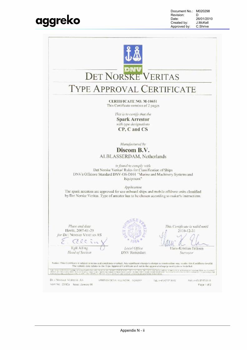
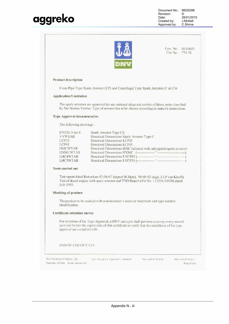
Spark Arrestor: DNV Certificate No M10651
5.10. ENGINE CONTROL SYSTEM An Electronic Cummins CM750 governor controls the engine output.
A Deep Sea Electronics protection module is used to monitor the safety circuits and set the operation mode of the generator. See section 6.1.2 Control Module for more detail.
5.11. GENERATOR Manufacturer: Newage Stamford
Type: HCI444E1
50Hz: 380-440 Volts Voltage Range
60Hz: 416-480 Volts
Voltage Regulator within 1% from no load to full load AS440
1 Phase configurable on Alternator TB
5.12. MAIN CIRCUIT BREAKER Manufacturer: Merlin Gerin
Type:
NS 1200N Fixed Three Pole, Electronic Overload Protection Micrologic 5.0 Motor Operated. Lockable Off Position
UL Approved
Document No.: M020298 Revision: D Date: 26/01/2010 Created by: J.McKell Approved by: C.Shrive
- 11 -
FUEL VALVE
OIL PRESSURE
GAUGE
SUMP PUMP
AMOT VALVE
(OFFSHORE ONLY)
RACOR FILTER
TWIN RACOR (OFFSHORE
ONLY)
TEMPERATURE
GAUGE
FUEL TANK VENT
Figure 5.1 - 300 kW Offshore Generator Part Locations
Document No.: M020298 Revision: D Date: 26/01/2010 Created by: J.McKell Approved by: C.Shrive
- 12 -
6.0 OPERATING INSTRUCTIONS 6.1. OPERATING CONTROLS AND INSTRUMENTS
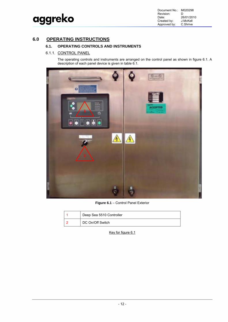
6.1.1. CONTROL PANEL The operating controls and instruments are arranged on the control panel as shown in figure 6.1. A description of each panel device is given in table 6.1.
Figure 6.1 – Control Panel Exterior
1 Deep Sea 5510 Controller
2 DC On/Off Switch
Key for figure 6.1
2
1
Document No.: M020298 Revision: D Date: 26/01/2010 Created by: J.McKell Approved by: C.Shrive
- 13 -
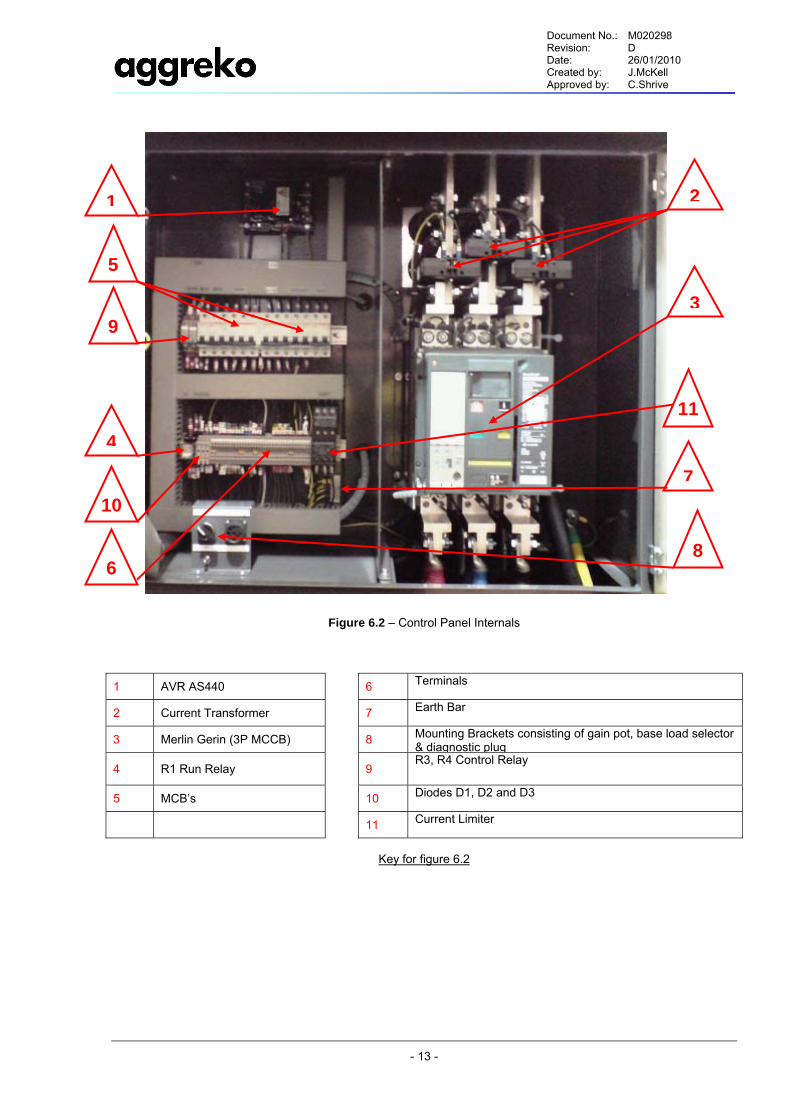
Figure 6.2 – Control Panel Internals
1 AVR AS440 6 Terminals
2 Current Transformer 7 Earth Bar
3 Merlin Gerin (3P MCCB) 8 Mounting Brackets consisting of gain pot, base load selector & diagnostic plug
4 R1 Run Relay
9 R3, R4 Control Relay
5 MCB’s 10 Diodes D1, D2 and D3
11 Current Limiter
Key for figure 6.2
1 2
6
7
8
3
4
5
9
10
11
Document No.: M020298 Revision: D Date: 26/01/2010 Created by: J.McKell Approved by: C.Shrive
- 14 -
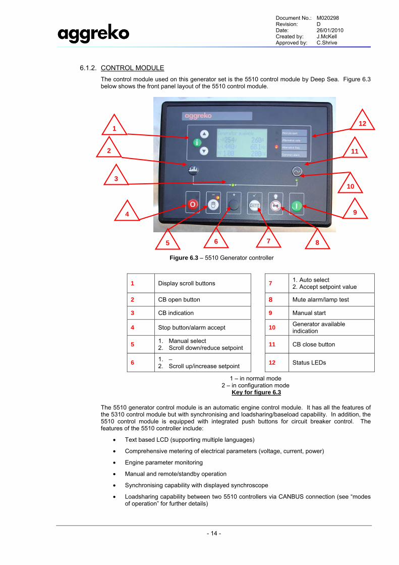
6.1.2. CONTROL MODULE The control module used on this generator set is the 5510 control module by Deep Sea. Figure 6.3 below shows the front panel layout of the 5510 control module.
The 5510 generator control module is an automatic engine control module. It has all the features of the 5310 control module but with synchronising and loadsharing/baseload capability. In addition, the 5510 control module is equipped with integrated push buttons for circuit breaker control. The features of the 5510 controller include:
• Text based LCD (supporting multiple languages)
• Comprehensive metering of electrical parameters (voltage, current, power)
• Engine parameter monitoring
• Manual and remote/standby operation
• Synchronising capability with displayed synchroscope
• Loadsharing capability between two 5510 controllers via CANBUS connection (see “modes of operation” for further details)
Figure 6.3 – 5510 Generator controller
1 Display scroll buttons
7 1. Auto select 2. Accept setpoint value
2 CB open button 8 Mute alarm/lamp test
3 CB indication 9 Manual start
4 Stop button/alarm accept
10 Generator available indication
5 1. Manual select 2. Scroll down/reduce setpoint
11 CB close button
6 1. – 2. Scroll up/increase setpoint
12 Status LEDs
1 – in normal mode 2 – in configuration mode
Key for figure 6.3
3
4
5 6
12
10
9
8 7
2 11
1
Document No.: M020298 Revision: D Date: 26/01/2010 Created by: J.McKell Approved by: C.Shrive
- 15 -
• Loadsharing capability between 5510 and older units with conventional parallel loadsharing lines (see “modes of operation” for further details)
• Baseload or parallel to mains operation (see “modes of operation” for further details)
• Comprehensive range of alarms
• Compatible with different alternator configurations
• Support of electronic engines via J1939 CANBUS interface
• On Aggreko canopy sets, binary inputs on the 5510 controller are configured for remote start input, circuit breaker status and alarms, e.g. Low fuel level or fuel spillage.
• Analogue inputs are typically configured for low oil pressure, high water temperature (either senders or discrete switches) and fuel gauge (where fitted).
• Binary outputs are configured for circuit breaker open and close and, where fitted, for Air flap closed (on offshore sets). In addition, one output is dedicated to provide a common alarm output which provides a positive DC signal in the event of any alarm.
6.1.3. DISPLAY PAGES The 5510 module displays the following pages on the LCD. Pressing the green Info button will scroll between these pages. Pressing the Up or Down arrow buttons will scroll between instrumentation parameters. If no parameters are selected, then autoscroll through the parameters with begin.
i. Status page
This shows the current status of the generator; e.g. generator at rest, manual mode, auto mode. When the generator is running, generator parameters are also shown (as displayed in figure 6.3).
ii. Engine instrumentation
Displays information related to the engine such as engine speed, battery voltage and run time. If connected to an electronic engine, a range of additional engine parameters are displayed which is dependent upon the engine type. These include parameters such as inlet temperature, turbo pressure and fuel consumption.
iii. Gen instrumentation
Displays electrical parameters relating to the engine. These include:
- Generator phase voltages
- Generator line voltages
- Frequency
- Generator currents
- Generator real power and apparent power
- Power factor and reactive power
- kWh
- Phase sequence
- Synchroscope
iv. Bus instrumentation
As the 5510 controller is capable of synchronising, bus information is displayed separately to generator information. This includes:
- Generator phase voltages
- Generator line voltages
- Frequency
- Phase sequence
v. Current alarm page
Displays the current alarms in clear text.
Document No.: M020298 Revision: D Date: 26/01/2010 Created by: J.McKell Approved by: C.Shrive
- 16 -
vi. Event log page
Stores the last 25 shutdown conditions and CB operations. Pressing the Up or Down arrow buttons will scroll through the event log.
6.1.4. FRONT PANEL LEDS The following LEDs are provided.
• Green LED to indicate circuit breaker closed [symbol 3 in figure 6.3]
• Green LED to indicate Generator available (lit after starting timers have expired) [symbol 10 in figure 6.3]
• Red LEDs for stop, manual and auto indication
• Status LEDs to indicate:
- Remote start input signal present.
- Alternative voltage selected. When alternative voltage is selected, under and overvoltage protection is halved. In addition, overcurrent protection is doubled. Alternative voltage is intended for use when the generator set alternator windings are configured in parallel, as opposed to series configuration.
- Alternative frequency selected. For US generator sets, normal frequency is 60Hz and alternative frequency is 50Hz. For European and AI generator sets, normal frequency is 50Hz and alternative frequency is 60Hz. When alternative frequency is selected protection settings for over/under frequency and over/under speed are moved accordingly.
- Common alarm indication. This LED is lit if any alarm condition is detected.
6.2. OPERATING PROCEDURE
CAUTION:- Always open the battery isolator switch to avoid unauthorised starting during transport and maintenance.
This section describes the basic operation of the generator set. For more details on the different modes of operation, see section 6.3 Modes of operation below.
6.2.1. MANUAL OPERATION To start generator:
1. Prior to starting, exercise daily maintenance. See section 7.1.
2. Turn on DC power.
3. Check that no alarms are present. If a shutdown condition is present, the generator set will not be allowed to start.
4. Ensure that the baseload switch inside the panel is OFF.
5. Press the manual select button. The display will read “Generator at rest” and “Waiting in Manual”.
6. Press the manual start button.
7. Once the generator has run-up to speed, check the frequency and voltage. Voltage can be adjusted via the AVR. Frequency can only be adjusted on non-electronic engines.
8. Walk around the engine and check for any leakages.
9. After the start up timers have expired, close the circuit breaker by pressing the CB close push button. Once the circuit breaker is closed, the 5510 will regulate the voltage and frequency to its nominal values. These can be adjusted from the front panel display. See section 6.5 Changing parameters for details on how to adjust these parameters.
To stop generator:
1. Open circuit breaker by pressing the CB open push button.
Document No.: M020298 Revision: D Date: 26/01/2010 Created by: J.McKell Approved by: C.Shrive
- 17 -
2. Allow the engine to cool down for at least 5 minutes, especially when the set has been running with a high load.
3. Press engine stop.
6.2.2. REMOTE/STANDBY OPERATION
CAUTION: In remote operation, motorised breakers will close automatically. The 5510 controller will close onto a dead bus or synchronise onto a live bus after the start-up timers have expired.
1. Turn on DC power
2. Check for alarms
3. Ensure that the busload switch inside the panel is OFF
4. Press Auto select. The display will read “Generator at rest” and “Auto mode”
5. The generator set can be started by providing a connection between terminals 2 and 3.
6. Generator set can be stopped by removing the connection between terminals 2 and 3.
7. A test run should be carried out at least once a week.
6.3. MODES OF OPERATION Please read section 6.2 Operating procedure for details on the basic operation of the 5510 controller. For 50 or 60 Hz operation (the vast majority of operating conditions) it will not be necessary to manually adjust the nominal frequency as this is automatically changed when alternative frequency is selected. For more details, see section 6.5 Changing parameters.
6.3.1. SINGLE SET OPERATION When used as a stand alone generator, the 5510 will regulate to its internal voltage and frequency nominal settings as soon as the breaker is closed. If any adjustment to frequency or voltage is made when the breaker is closed, the controller will regulate back to its nominal setpoints.
6.3.2. LOADSHARING WITH ANOTHER 5510 CONTROLLER Loadsharing between 2 or more 5510 controllers is achieved via the Multiset Communications (MSC) CANBUS link.
Communications link
The connection is made using 2 core screened cable. See diagram 6.4 below.
Document No.: M020298 Revision: D Date: 26/01/2010 Created by: J.McKell Approved by: C.Shrive
- 18 -
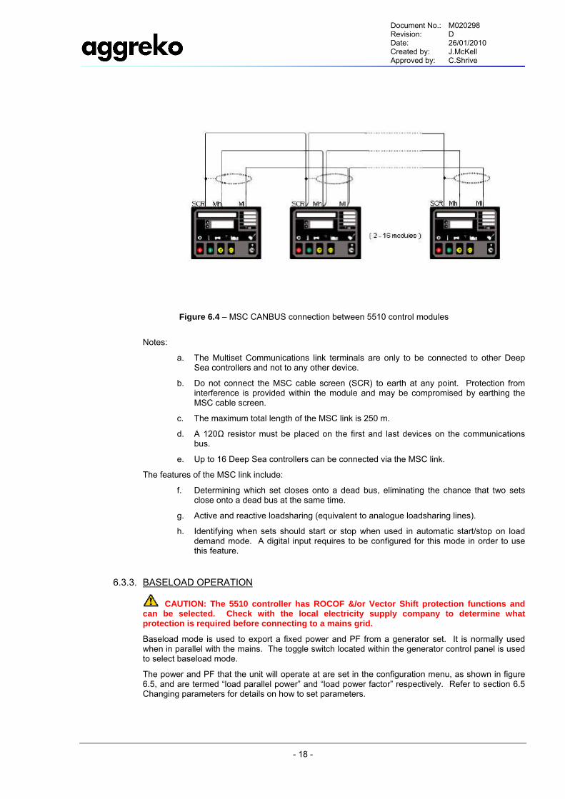
Notes:
a. The Multiset Communications link terminals are only to be connected to other Deep Sea controllers and not to any other device.
b. Do not connect the MSC cable screen (SCR) to earth at any point. Protection from interference is provided within the module and may be compromised by earthing the MSC cable screen.
c. The maximum total length of the MSC link is 250 m.
d. A 120Ω resistor must be placed on the first and last devices on the communications bus.
e. Up to 16 Deep Sea controllers can be connected via the MSC link.
The features of the MSC link include:
f. Determining which set closes onto a dead bus, eliminating the chance that two sets close onto a dead bus at the same time.
g. Active and reactive loadsharing (equivalent to analogue loadsharing lines).
h. Identifying when sets should start or stop when used in automatic start/stop on load demand mode. A digital input requires to be configured for this mode in order to use this feature.
6.3.3. BASELOAD OPERATION
CAUTION: The 5510 controller has ROCOF &/or Vector Shift protection functions and can be selected. Check with the local electricity supply company to determine what protection is required before connecting to a mains grid.
Baseload mode is used to export a fixed power and PF from a generator set. It is normally used when in parallel with the mains. The toggle switch located within the generator control panel is used to select baseload mode.
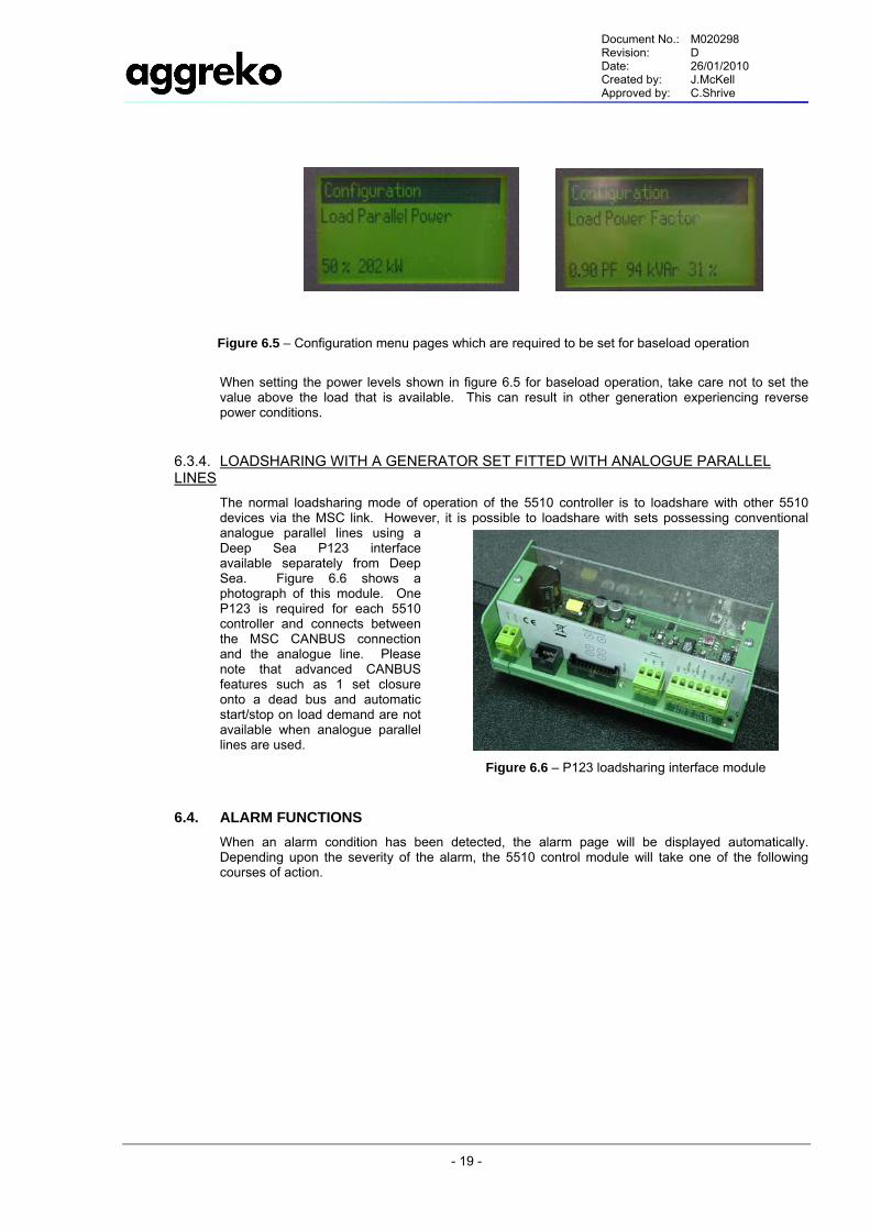
The power and PF that the unit will operate at are set in the configuration menu, as shown in figure 6.5, and are termed “load parallel power” and “load power factor” respectively. Refer to section 6.5 Changing parameters for details on how to set parameters.
Figure 6.4 – MSC CANBUS connection between 5510 control modules
Document No.: M020298 Revision: D Date: 26/01/2010 Created by: J.McKell Approved by: C.Shrive
- 19 -
When setting the power levels shown in figure 6.5 for baseload operation, take care not to set the value above the load that is available. This can result in other generation experiencing reverse power conditions.
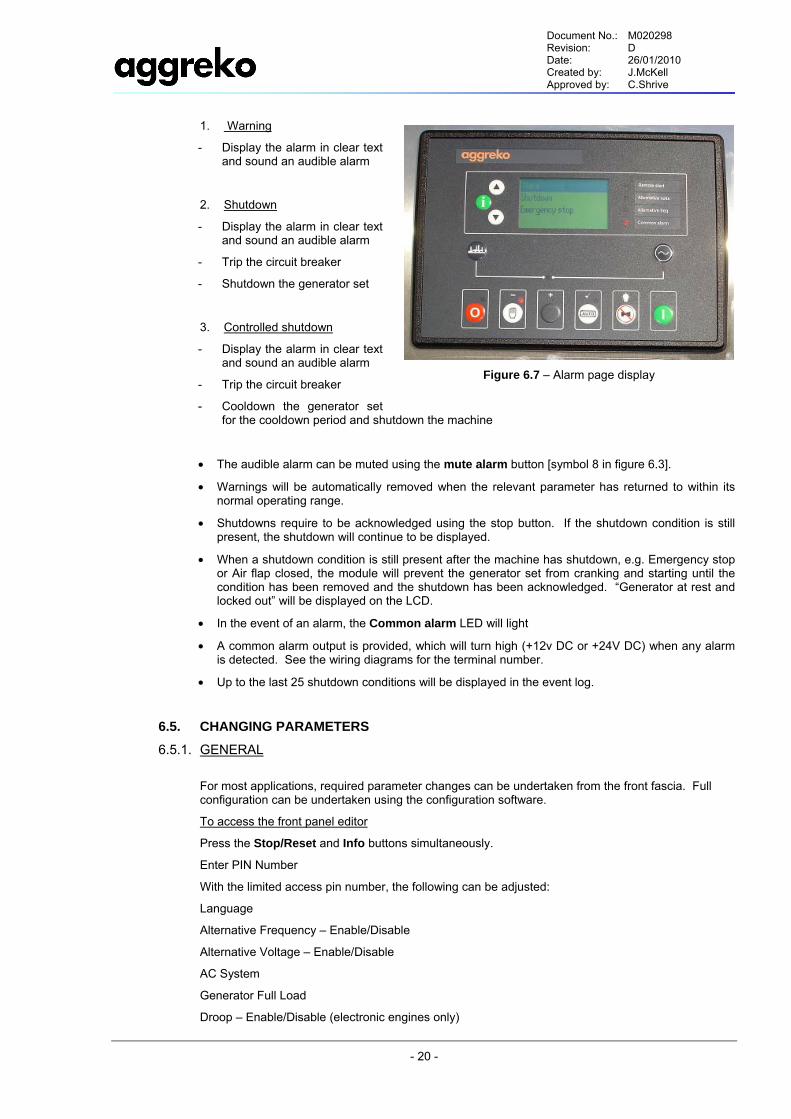
6.3.4. LOADSHARING WITH A GENERATOR SET FITTED WITH ANALOGUE PARALLEL LINES
The normal loadsharing mode of operation of the 5510 controller is to loadshare with other 5510 devices via the MSC link. However, it is possible to loadshare with sets possessing conventional analogue parallel lines using a Deep Sea P123 interface available separately from Deep Sea. Figure 6.6 shows a photograph of this module. One P123 is required for each 5510 controller and connects between the MSC CANBUS connection and the analogue line. Please note that advanced CANBUS features such as 1 set closure onto a dead bus and automatic start/stop on load demand are not available when analogue parallel lines are used.
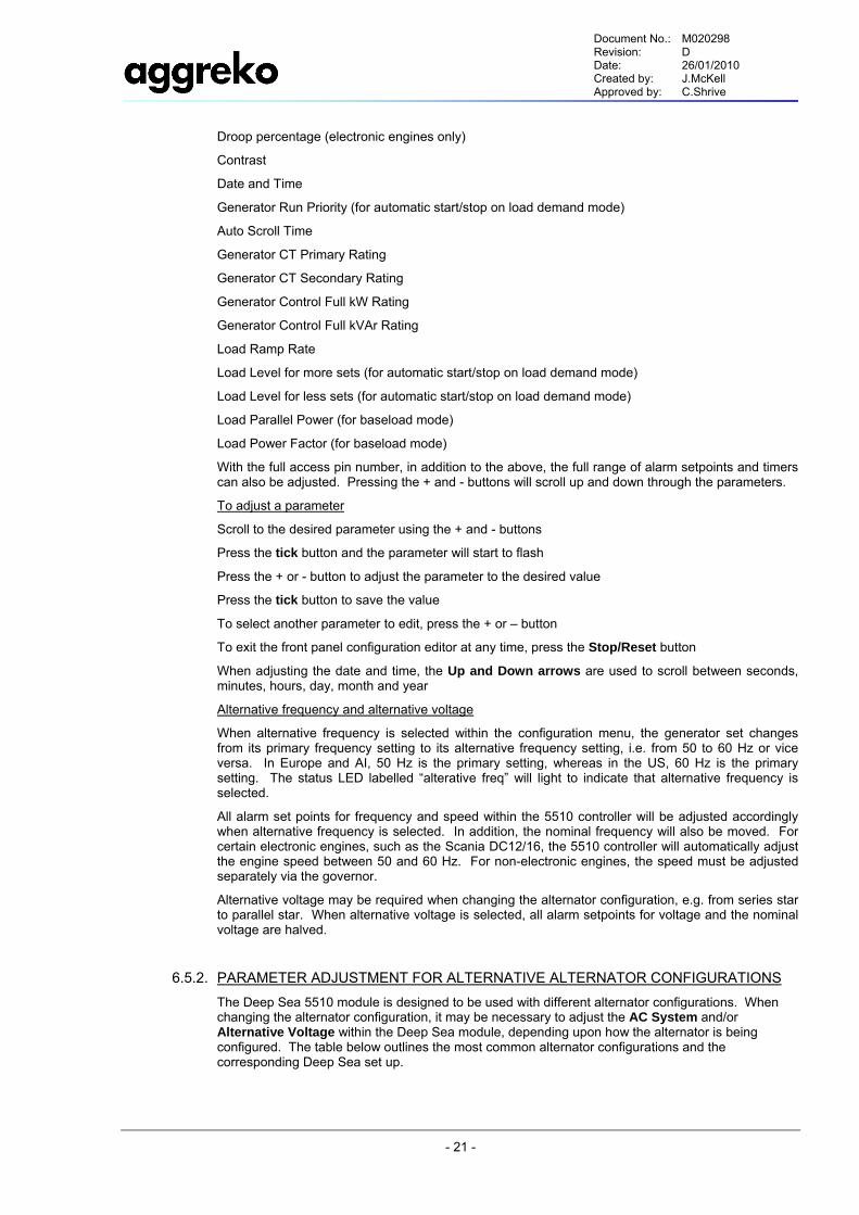
6.4. ALARM FUNCTIONS When an alarm condition has been detected, the alarm page will be displayed automatically. Depending upon the severity of the alarm, the 5510 control module will take one of the following courses of action.
Figure 6.5 – Configuration menu pages which are required to be set for baseload operation
Figure 6.6 – P123 loadsharing interface module
Document No.: M020298 Revision: D Date: 26/01/2010 Created by: J.McKell Approved by: C.Shrive
- 20 -
1. Warning
- Display the alarm in clear text and sound an audible alarm
2. Shutdown
- Display the alarm in clear text and sound an audible alarm
- Trip the circuit breaker
- Shutdown the generator set
3. Controlled shutdown
- Display the alarm in clear text and sound an audible alarm
- Trip the circuit breaker
- Cooldown the generator set for the cooldown period and shutdown the machine
• The audible alarm can be muted using the mute alarm button [symbol 8 in figure 6.3].
• Warnings will be automatically removed when the relevant parameter has returned to within its normal operating range.
• Shutdowns require to be acknowledged using the stop button. If the shutdown condition is still present, the shutdown will continue to be displayed.
• When a shutdown condition is still present after the machine has shutdown, e.g. Emergency stop or Air flap closed, the module will prevent the generator set from cranking and starting until the condition has been removed and the shutdown has been acknowledged. “Generator at rest and locked out” will be displayed on the LCD.
• In the event of an alarm, the Common alarm LED will light
• A common alarm output is provided, which will turn high (+12v DC or +24V DC) when any alarm is detected. See the wiring diagrams for the terminal number.
• Up to the last 25 shutdown conditions will be displayed in the event log.
6.5. CHANGING PARAMETERS
6.5.1. GENERAL
For most applications, required parameter changes can be undertaken from the front fascia. Full configuration can be undertaken using the configuration software.
To access the front panel editor
Press the Stop/Reset and Info buttons simultaneously.
Enter PIN Number
With the limited access pin number, the following can be adjusted:
Language
Alternative Frequency – Enable/Disable
Alternative Voltage – Enable/Disable
AC System
Generator Full Load
Droop – Enable/Disable (electronic engines only)
Figure 6.7 – Alarm page display
Document No.: M020298 Revision: D Date: 26/01/2010 Created by: J.McKell Approved by: C.Shrive
- 21 -
Droop percentage (electronic engines only)
Contrast
Date and Time
Generator Run Priority (for automatic start/stop on load demand mode)
Auto Scroll Time
Generator CT Primary Rating
Generator CT Secondary Rating
Generator Control Full kW Rating
Generator Control Full kVAr Rating
Load Ramp Rate
Load Level for more sets (for automatic start/stop on load demand mode)
Load Level for less sets (for automatic start/stop on load demand mode)
Load Parallel Power (for baseload mode)
Load Power Factor (for baseload mode)
With the full access pin number, in addition to the above, the full range of alarm setpoints and timers can also be adjusted. Pressing the + and - buttons will scroll up and down through the parameters.
To adjust a parameter
Scroll to the desired parameter using the + and - buttons
Press the tick button and the parameter will start to flash
Press the + or - button to adjust the parameter to the desired value
Press the tick button to save the value
To select another parameter to edit, press the + or – button
To exit the front panel configuration editor at any time, press the Stop/Reset button
When adjusting the date and time, the Up and Down arrows are used to scroll between seconds, minutes, hours, day, month and year
Alternative frequency and alternative voltage
When alternative frequency is selected within the configuration menu, the generator set changes from its primary frequency setting to its alternative frequency setting, i.e. from 50 to 60 Hz or vice versa. In Europe and AI, 50 Hz is the primary setting, whereas in the US, 60 Hz is the primary setting. The status LED labelled “alterative freq” will light to indicate that alternative frequency is selected.
All alarm set points for frequency and speed within the 5510 controller will be adjusted accordingly when alternative frequency is selected. In addition, the nominal frequency will also be moved. For certain electronic engines, such as the Scania DC12/16, the 5510 controller will automatically adjust the engine speed between 50 and 60 Hz. For non-electronic engines, the speed must be adjusted separately via the governor.
Alternative voltage may be required when changing the alternator configuration, e.g. from series star to parallel star. When alternative voltage is selected, all alarm setpoints for voltage and the nominal voltage are halved.
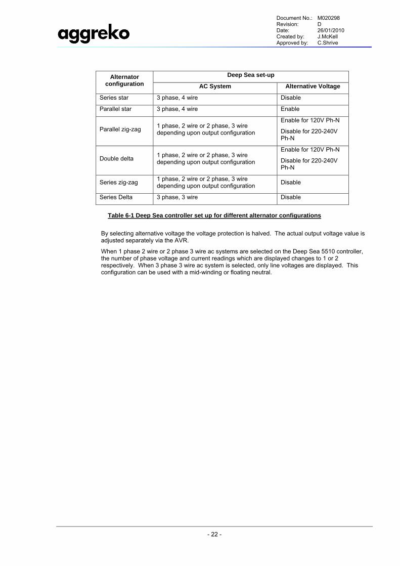
6.5.2. PARAMETER ADJUSTMENT FOR ALTERNATIVE ALTERNATOR CONFIGURATIONS The Deep Sea 5510 module is designed to be used with different alternator configurations. When changing the alternator configuration, it may be necessary to adjust the AC System and/or Alternative Voltage within the Deep Sea module, depending upon how the alternator is being configured. The table below outlines the most common alternator configurations and the corresponding Deep Sea set up.
Document No.: M020298 Revision: D Date: 26/01/2010 Created by: J.McKell Approved by: C.Shrive
- 22 -
Deep Sea set-up Alternator configuration AC System Alternative Voltage
Series star 3 phase, 4 wire Disable
Parallel star 3 phase, 4 wire Enable
Parallel zig-zag 1 phase, 2 wire or 2 phase, 3 wire depending upon output configuration
Enable for 120V Ph-N
Disable for 220-240V Ph-N
Double delta 1 phase, 2 wire or 2 phase, 3 wire depending upon output configuration
Enable for 120V Ph-N
Disable for 220-240V Ph-N
Series zig-zag 1 phase, 2 wire or 2 phase, 3 wire depending upon output configuration Disable
Series Delta 3 phase, 3 wire Disable
Table 6-1 Deep Sea controller set up for different alternator configurations
By selecting alternative voltage the voltage protection is halved. The actual output voltage value is adjusted separately via the AVR.
When 1 phase 2 wire or 2 phase 3 wire ac systems are selected on the Deep Sea 5510 controller, the number of phase voltage and current readings which are displayed changes to 1 or 2 respectively. When 3 phase 3 wire ac system is selected, only line voltages are displayed. This configuration can be used with a mid-winding or floating neutral.
Document No.: M020298 Revision: D Date: 26/01/2010 Created by: J.McKell Approved by: C.Shrive
- 23 -
7.0 MAINTENANCE 7.1. GENERAL
In addition to periodic inspections, many of the components in these units require periodic servicing to provide maximum output and performance. Servicing may consist of pre-operation and post-operation procedures to be performed by the operating or maintenance personnel. The primary function of preventive maintenance is to prevent failure, and consequently, the need for repair. Preventive maintenance is the easiest and the least expensive type of maintenance. Maintaining your unit and keeping it clean at all times will facilitate servicing.
Ensure that maintenance personnel are adequately trained, competent and have read the Maintenance Manuals.
Prior to attempting any maintenance work, be aware of the following:
Any unauthorized modification or failure to maintain this equipment may make it unsafe and out of factory warranty.
Use extreme care to avoid contacting hot surfaces (engine exhaust manifold and piping, etc.).
Never operate this machine with any guards removed.
Imperial and Metric hardware was used in the design and assembly of this unit. Consult the parts manual for clarification of usage.
The machine cannot be started accidentally or otherwise, by posting warning signs and/or fitting appropriate anti–start devices.
All residual electrical power sources (mains and battery) are isolated.
Prior to opening or removing panels or covers to work inside a machine, ensure that:
Anyone entering the machine is aware of the reduced level of protection and the additional hazards, including hot surfaces and intermittently moving parts.
The machine cannot be started accidentally or otherwise, by posting warning signs and/or fitting appropriate anti–start devices.
Prior to attempting any maintenance work on a running machine, ensure that:
The work carried out is limited to only those tasks which require the machine to run.
The work carried out with safety protection devices disabled or removed is limited to only those tasks which require the machine to be running with safety protection devices disabled or removed.
All hazards present are known (e.g. pressurised components, electrically live components, removed panels, covers and guards, extreme temperatures, inflow and outflow of air, intermittently moving parts, safety valve discharge etc.).
Appropriate personal protective equipment is worn.
Loose clothing, jewellery, long hair etc. is made safe.
Warning signs indicating that Maintenance Work is in Progress are posted in a position that can be clearly seen.
Upon completion of maintenance tasks and prior to returning the machine into service, ensure that:
The machine is suitably tested.
All guards and safety protection devices are refitted.
All panels are replaced, canopy and doors closed.
Hazardous materials are effectively contained and disposed of.
To assist with ordering spare parts and other service activities, a short form list of Component Manufacturers data has been included in this manual.
Prior to engine starting, check the oil and coolant levels.
Carry out a visual check of the following:
Leaks.
Loose or damage parts.
Document No.: M020298 Revision: D Date: 26/01/2010 Created by: J.McKell Approved by: C.Shrive
- 24 -
Worn or damaged belts, change in engine appearance.
Refer to the Maintenance Schedule for quick reference.
Report unusual noise/vibration and/or exhaust smoke and ensure the generator set is kept clean, both inside and out.
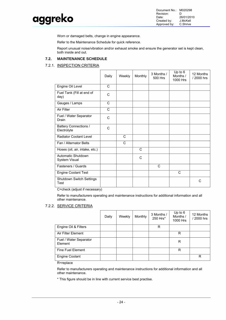
7.2. MAINTENANCE SCHEDULE
7.2.1. INSPECTION CRITERIA
Daily Weekly Monthly 3 Months / 500 Hrs
Up to 6 Months / 1000 Hrs
12 Months / 2000 hrs
Engine Oil Level C
Fuel Tank (Fill at end of day) C
Gauges / Lamps C
Air Filter C
Fuel / Water Separator Drain C
Battery Connections / Electrolyte C
Radiator Coolant Level C
Fan / Alternator Belts C
Hoses (oil, air, intake, etc.) C
Automatic Shutdown System Visual C
Fasteners / Guards C
Engine Coolant Test C
Shutdown Switch Settings Test C
C=check (adjust if necessary)
Refer to manufacturers operating and maintenance instructions for additional information and all other maintenance.
7.2.2. SERVICE CRITERIA
Daily Weekly Monthly 3 Months / 250 Hrs*
Up to 6 Months / 1000 Hrs
12 Months / 2000 hrs
Engine Oil & Filters R
Air Filter Element R
Fuel / Water Separator Element R
Fine Fuel Element R
Engine Coolant R
R=replace
Refer to manufacturers operating and maintenance instructions for additional information and all other maintenance.
* This figure should be in line with current service best practise.
Document No.: M020298 Revision: D Date: 26/01/2010 Created by: J.McKell Approved by: C.Shrive
- 25 -
7.3. DAILY MAINTENANCE
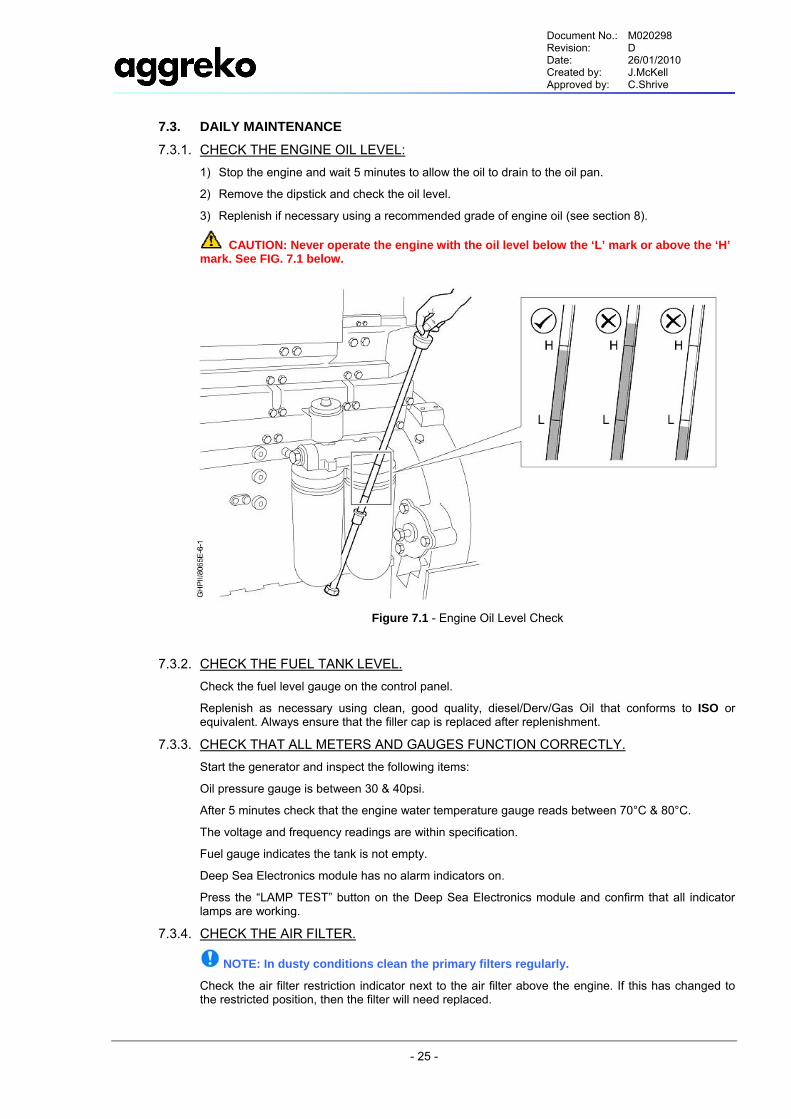
7.3.1. CHECK THE ENGINE OIL LEVEL: 1) Stop the engine and wait 5 minutes to allow the oil to drain to the oil pan.
2) Remove the dipstick and check the oil level.
3) Replenish if necessary using a recommended grade of engine oil (see section 8).
CAUTION: Never operate the engine with the oil level below the ‘L’ mark or above the ‘H’ mark. See FIG. 7.1 below.
Figure 7.1 - Engine Oil Level Check
7.3.2. CHECK THE FUEL TANK LEVEL. Check the fuel level gauge on the control panel.
Replenish as necessary using clean, good quality, diesel/Derv/Gas Oil that conforms to ISO or equivalent. Always ensure that the filler cap is replaced after replenishment.
7.3.3. CHECK THAT ALL METERS AND GAUGES FUNCTION CORRECTLY. Start the generator and inspect the following items:
Oil pressure gauge is between 30 & 40psi.
After 5 minutes check that the engine water temperature gauge reads between 70°C & 80°C.
The voltage and frequency readings are within specification.
Fuel gauge indicates the tank is not empty.
Deep Sea Electronics module has no alarm indicators on.
Press the “LAMP TEST” button on the Deep Sea Electronics module and confirm that all indicator lamps are working.
7.3.4. CHECK THE AIR FILTER.
NOTE: In dusty conditions clean the primary filters regularly.
Check the air filter restriction indicator next to the air filter above the engine. If this has changed to the restricted position, then the filter will need replaced.
Document No.: M020298 Revision: D Date: 26/01/2010 Created by: J.McKell Approved by: C.Shrive
- 26 -
7.3.5. CHECK THE BATTERY. Check that the battery connections are properly installed and that the electrolyte level in each cell covers the top plates. If necessary, top up with clean distilled water.
7.3.6. CHECK FOR LEAKS. There are several fluids used inside the generator, e.g. diesel, oil, coolant. Look for signs of leakage all around the engine.
Any source of leak should be checked and fixed. Clean up any fluid lying inside the generator and dispose of according to the appropriate local regulations.
Recurring leaks should be reported to AGGREKO.
7.4. WEEKLY MAINTENANCE
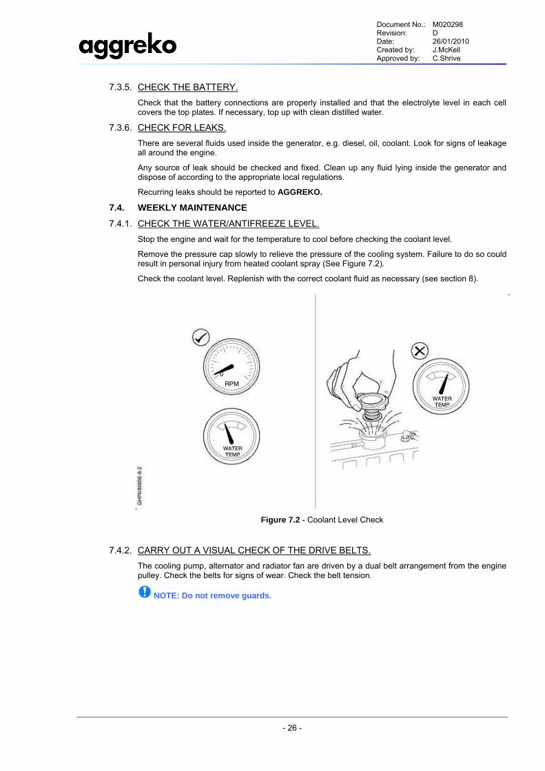
7.4.1. CHECK THE WATER/ANTIFREEZE LEVEL. Stop the engine and wait for the temperature to cool before checking the coolant level.
Remove the pressure cap slowly to relieve the pressure of the cooling system. Failure to do so could result in personal injury from heated coolant spray (See Figure 7.2).
Check the coolant level. Replenish with the correct coolant fluid as necessary (see section 8).
Figure 7.2 - Coolant Level Check
7.4.2. CARRY OUT A VISUAL CHECK OF THE DRIVE BELTS. The cooling pump, alternator and radiator fan are driven by a dual belt arrangement from the engine pulley. Check the belts for signs of wear. Check the belt tension.
NOTE: Do not remove guards.
Document No.: M020298 Revision: D Date: 26/01/2010 Created by: J.McKell Approved by: C.Shrive
- 27 -
8.0 LUBRICATION 8.1. GENERAL INFORMATION
Lubrication is an essential part of preventive maintenance, affecting to a great extent the useful life of the unit. Different lubricants are needed and some components in the unit require more frequent lubrication than others. Therefore, it is important that the instructions regarding types of lubricants and the frequency of their application be explicitly followed. Periodic lubrication of the moving parts reduces to a minimum the possibility of mechanical failures.
The Preventive Maintenance Schedule shows those items requiring regular service and the interval in which they should be performed. A regular service program should be developed to include all items and fluids. These intervals are based on average operating conditions. In the event of extremely severe (hot, cold, dusty or wet) operating conditions, more frequent lubrication than specified may be necessary. Details concerning lubrication of the running gear are in Maintenance Section.
8.2. GENERATOR OIL CHANGE These units are normally furnished with an initial supply of oil sufficient to allow operation of the unit for approximately 6 months or 250 hours, whichever comes first. The unit will however need to be topped up with oil during this period. If a unit has been completely drained of all oil, it must be refilled with new oil before it is placed in operation. Refer to specifications in Lubrication Table.
NOTICE: Some oil types are incompatible when mixed and result in the formation of varnishes, shellacs, or lacquers that may be insoluble. Such deposits can cause serious problems including clogging of the filters. Where possible, do NOT mix oils of different types and avoid mixing different brands. A type or brand change is best made at the time of a complete oil drain and refill.
If the unit has been operated for the time/ hours mentioned above, it should be completely drained of oil. If the unit has been operated under adverse conditions, or after long periods in storage, an earlier change period may be necessary as oil deteriorates with time as well as by operating conditions.
An oil change is good insurance against the accumulation of dirt, sludge, or oxidized oil products.
Completely drain the reservoir, piping, and Purafiner system. If the oil is drained immediately after the unit has been run for some time, most of the sediment will be in suspension and, therefore, will drain more readily. However, the fluid will be hot and care must be taken to avoid contact with the skin or eyes.
After the unit has been completely drained of all old fluid, close the drain valve. Add oil in the specified quantity at the filler plug. Tighten the filler plug and run the machine to circulate the oil. Check the oil level when unit is warm and not running. If not near the middle of the dipstick, stop the unit and make corrections. DO NOT OVERFILL.
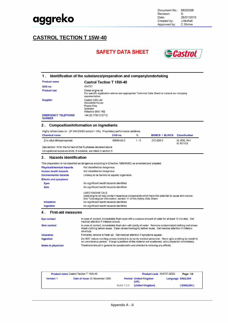
8.3. OIL SPECIFICATION The oil required for this engine is:
Manufacturer: Castrol
Product Name: Tection T 15W-40 (Formerly RX Super Plus)
Relative Density @ 25°C 0.89 g/cm³
Viscosity @ 40°C 110 mm²/s
Viscosity @ 100°C 14.5 mm²/s
Viscosity Index 135
CCS –20ºC 6450 mPA.s
Total Base Number (TBN) 11.6 mgKOH/g
Flash Point (COC) 228 °C
Pour Point -36 °C
Sulphated Ash 1.5 %m
Document No.: M020298 Revision: D Date: 26/01/2010 Created by: J.McKell Approved by: C.Shrive
- 28 -
9.0 TROUBLE SHOOTING 9.1. INTRODUCTION
Trouble shooting for a generator set is an organized study of a particular problem or series of problems and a planned method of procedure for investigation and correction. The trouble-shooting chart that follows in Section 9.3 includes some of the problems that an operator may encounter during the operation of a generator set.
The chart does not attempt to list all of the troubles that may occur, nor does it attempt to give all of the answers for correction of the problems. The chart does give those problems that are most probable to occur. To use the trouble shooting chart:
4) Find the problem being experienced in the Symptom column on the far left.
5) Proceed to work through the possible causes in the next column, instigating the appropriate corrective action where required from the next column.
9.2. ACTION PLAN A. Think Before Acting: Study the problem thoroughly and ask yourself these questions:
1) What were the warning signals that preceded the trouble? 2) Has a similar trouble occurred before? 3) What previous maintenance work has been done? If the generator will still operate, is it safe to continue operating it to make further checks?
B. Do The Simplest Things First: Most problems are simple and easily corrected. Always check the easiest and most obvious things first, following this simple rule will save time and trouble.
Note: For trouble shooting electrical problems, refer to the Wiring Diagram Schematic found in Appendix C.
C. Double Check Before Disassembly: The source of most generator troubles can be traced not to one component alone, but to the relationship of one component with another. Too often, a generator can be partially disassembled in search of the cause of a certain trouble and all evidence is destroyed during disassembly. Check again to be sure an easy solution to the problem has not been overlooked.
D. Find And Correct Basic Cause: After a mechanical failure has been corrected, be sure to locate and correct the cause of the trouble so the same failure will not be repeated. A complaint of "premature breakdown" may be corrected by repairing any improper wiring connections, but something caused the defective wiring. The cause may be excessive vibration.
Document No.: M020298 Revision: D Date: 26/01/2010 Created by: J.McKell Approved by: C.Shrive
- 29 -
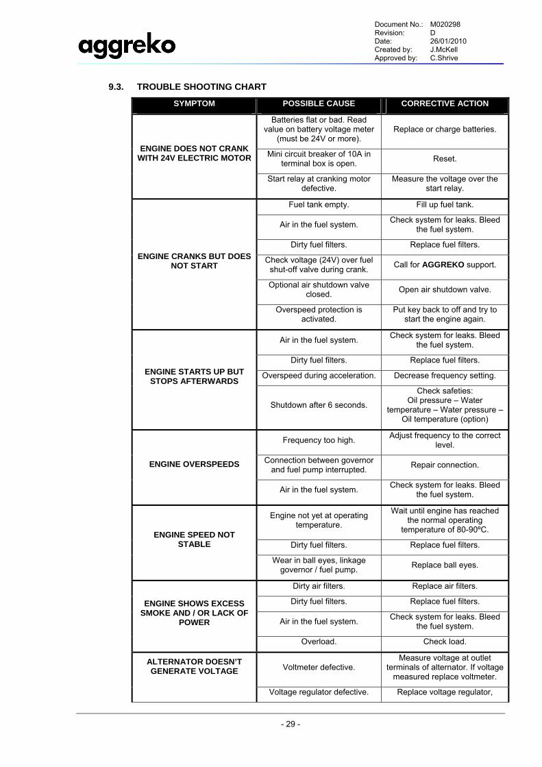
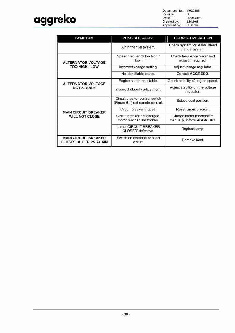
9.3. TROUBLE SHOOTING CHART
SYMPTOM POSSIBLE CAUSE CORRECTIVE ACTION
Batteries flat or bad. Read value on battery voltage meter
(must be 24V or more). Replace or charge batteries.
Mini circuit breaker of 10A in terminal box is open. Reset.
ENGINE DOES NOT CRANK WITH 24V ELECTRIC MOTOR
Start relay at cranking motor defective.
Measure the voltage over the start relay.
Fuel tank empty. Fill up fuel tank.
Air in the fuel system. Check system for leaks. Bleed the fuel system.
Dirty fuel filters. Replace fuel filters.
Check voltage (24V) over fuel shut-off valve during crank. Call for AGGREKO support.
Optional air shutdown valve closed. Open air shutdown valve.
ENGINE CRANKS BUT DOES NOT START
Overspeed protection is activated.
Put key back to off and try to start the engine again.
Air in the fuel system. Check system for leaks. Bleed the fuel system.
Dirty fuel filters. Replace fuel filters.
Overspeed during acceleration. Decrease frequency setting. ENGINE STARTS UP BUT STOPS AFTERWARDS
Shutdown after 6 seconds.
Check safeties: Oil pressure – Water
temperature – Water pressure – Oil temperature (option)
Frequency too high. Adjust frequency to the correct level.
Connection between governor and fuel pump interrupted. Repair connection. ENGINE OVERSPEEDS
Air in the fuel system. Check system for leaks. Bleed the fuel system.
Engine not yet at operating temperature.
Wait until engine has reached the normal operating
temperature of 80-90ºC.
Dirty fuel filters. Replace fuel filters. ENGINE SPEED NOT
STABLE
Wear in ball eyes, linkage governor / fuel pump. Replace ball eyes.
Dirty air filters. Replace air filters.
Dirty fuel filters. Replace fuel filters.
Air in the fuel system. Check system for leaks. Bleed the fuel system.
ENGINE SHOWS EXCESS SMOKE AND / OR LACK OF
POWER
Overload. Check load.
Voltmeter defective. Measure voltage at outlet
terminals of alternator. If voltage measured replace voltmeter.
ALTERNATOR DOESN’T GENERATE VOLTAGE
Voltage regulator defective. Replace voltage regulator,
Document No.: M020298 Revision: D Date: 26/01/2010 Created by: J.McKell Approved by: C.Shrive
- 30 -
SYMPTOM POSSIBLE CAUSE CORRECTIVE ACTION
Air in the fuel system. Check system for leaks. Bleed the fuel system.
Speed frequency too high / low.
Check frequency meter and adjust if required.
Incorrect voltage setting. Adjust voltage regulator. ALTERNATOR VOLTAGE
TOO HIGH / LOW
No identifiable cause. Consult AGGREKO.
Engine speed not stable. Check stability of engine speed. ALTERNATOR VOLTAGE
NOT STABLE Incorrect stability adjustment. Adjust stability on the voltage regulator.
Circuit breaker control switch (Figure 6.1) set remote control. Select local position.
Circuit breaker tripped. Reset circuit breaker.
Circuit breaker not charged, motor mechanism broken.
Charge motor mechanism manually, inform AGGREKO.
MAIN CIRCUIT BREAKER WILL NOT CLOSE
Lamp ‘CIRCUIT BREAKER CLOSED’ defective. Replace lamp.
MAIN CIRCUIT BREAKER CLOSES BUT TRIPS AGAIN
Switch on overload or short circuit. Remove load.

Document No.: M020298 Revision: D Date: 26/01/2010 Created by: J.McKell Approved by: C.Shrive
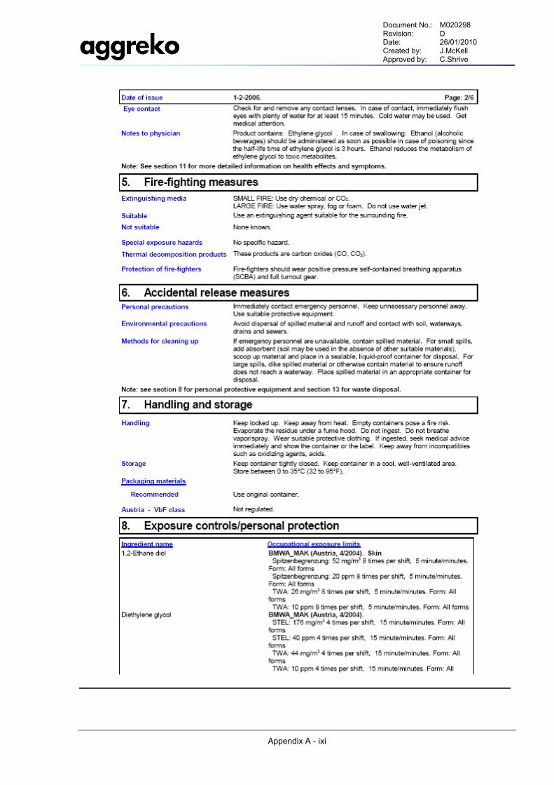
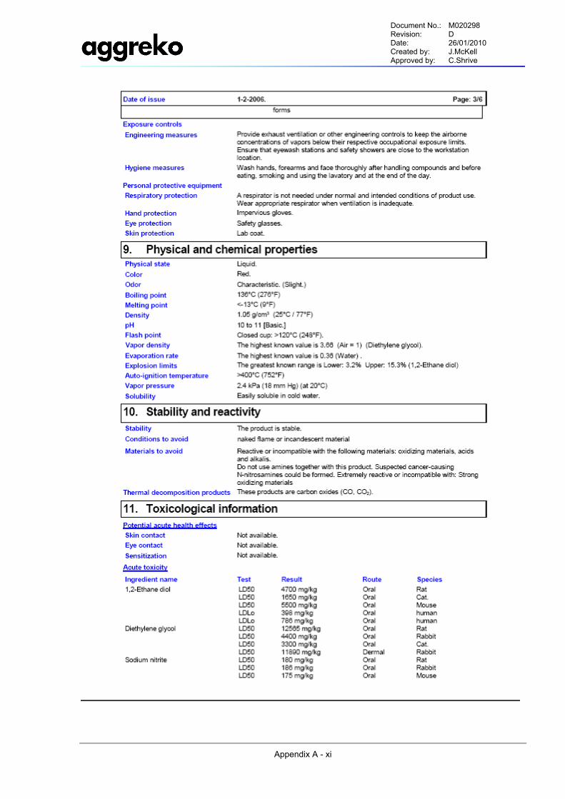
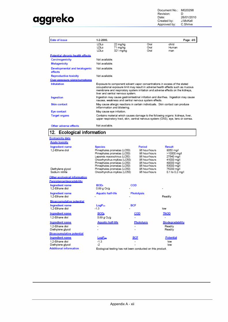
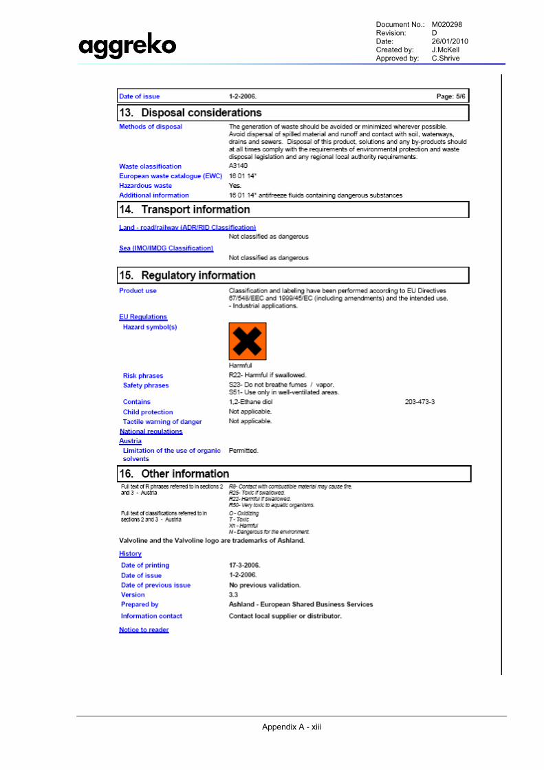
Appendix A - ii
MATERIAL SAFETY DATA SHEETS
APP
END
IX A
Document No.: M020298 Revision: D Date: 26/01/2010 Created by: J.McKell Approved by: C.Shrive
Appendix A - iii
CASTROL TECTION T 15W-40
Document No.: M020298 Revision: D Date: 26/01/2010 Created by: J.McKell Approved by: C.Shrive
Appendix A - iiii
Document No.: M020298 Revision: D Date: 26/01/2010 Created by: J.McKell Approved by: C.Shrive
Appendix A - ivi
Document No.: M020298 Revision: D Date: 26/01/2010 Created by: J.McKell Approved by: C.Shrive
Appendix A - vi
Document No.: M020298 Revision: D Date: 26/01/2010 Created by: J.McKell Approved by: C.Shrive
Appendix A - vii
LEAD ACID BATTERIES
HEALTH & SAFETY LEAD ACID BATTERIES #################################
The handling and proper use of lead-acid batteries is not hazardous provided sensible precautions are observed and that Operatives having been trained in their use are adequately supervised. The purpose of this letter is threefold:- [ i] to indicate potential hazards that may arise. [ ii] to outline the precautions to be taken to minimise such hazards. [iii] to indicate action to be taken in the event of an accident. 1. SULPHURIC ACID [S.G. 1.260 - 1.300] Batteries contain sulphuric acid which may leak for a variety of reasons and may be given off as droplets and/or spray during recharging. [The Hazards] Sulphuric Acid is a poisonous and corrosive clear liquid which can burn/irritate skin and eyes and could burn clothing. [Precautions] Always handle batteries with care Always store upright Never over-fill with acid Always charge in a well ventilated area. Maximum voltage 15v per each 12v Battery. Use eye protection and protective clothing if there is any risk of acid splashing. [Emergency Action] Skin Contact: Immediately wash the affected area with copious amounts of clean water. Remove any contaminated clothing. Eye Contact Immediately irrigate eyes for at least 10 minutes with clean water. Swallowing Make the victim drink volumes of water, milk or milk of magnesia. DO NOT GIVE EMETIC In all cases seek medical attention. Speed of action is vital. [Spillages] Small spillages can be swilled away with volumes of water. [Disposal] See Section 5. 2. ELECTRICAL ENERGY [The Hazards] The accidental connection of battery terminals by conductive objects, e.g. metal tools or metal personal jewellery etc., may generate sufficient heat to cause burns, create arcing or cause molten metal to splash.
Document No.: M020298 Revision: D Date: 26/01/2010 Created by: J.McKell Approved by: C.Shrive
Appendix A - viii
[PAGE TWO]. [Precautions] Always ensure correct installation. The positive cable must be attached to the terminal marked [+] and the negative to the terminal marked [-]. Cables and terminals should be kept clean and securely fitted. Before using metallic tools on a battery remove metallic objects from hands and wrists. Before working on a vehicle electrical system disconnect the Battery, disconnecting the earth strap first and reconnecting last. Do not place tools on top of batteries. [Emergency Action] Burns: Apply sterile bandage. Electric Shock: Approach victim with care. Switch off or otherwise break current. If not possible, detach victim from contact by means of insulating material [wood, rubber or plastic hosepipe, folded newspaper etc] Do not touch with bare hands. In each case seek medical advice. Speed of action is vital. 3. EMISSION OF GASES A mixture of oxygen and hydrogen is emitted during charging and may be emitted if a battery is moved or shaken. [The Hazards] An explosive atmosphere exists if the concentration of hydrogen exceeds 4%. [Precautions] Always charge in a well ventilated environment. No naked flames NO SMOKING Be certain that current is switched off before making breaking connection. Always remove earth strap first and re-connect last. [Emergency Action] Explosion: Seek medical advice remembering that acid may have been sprayed. 4. WEIGHT In general terms batteries are heavy and awkward to handle. Care should be taken and correct lifting techniques employed. 5. DISPOSAL Batteries, Battery Acid, Lead and Lead compounds must be disposed of in accordance with: [a] The deposit of Poisonous Waste Act 1972 [b] The Control of Pollution Act 1974 [c] Consumer Protection Act 1987 If in doubt, consult the Environmental Department of your Local Authority. For further information refer to:- BRITISH STANDARD BS 6604; 1985 SAFE OPERATION OF STARTER BATTERIES.
Document No.: M020298 Revision: D Date: 26/01/2010 Created by: J.McKell Approved by: C.Shrive
Appendix A - viiii
Valvoline HD Extended Life RTU
Document No.: M020298 Revision: D Date: 26/01/2010 Created by: J.McKell Approved by: C.Shrive
Appendix A - ixi
Document No.: M020298 Revision: D Date: 26/01/2010 Created by: J.McKell Approved by: C.Shrive
Appendix A - xi
Document No.: M020298 Revision: D Date: 26/01/2010 Created by: J.McKell Approved by: C.Shrive
Appendix A - xii
Document No.: M020298 Revision: D Date: 26/01/2010 Created by: J.McKell Approved by: C.Shrive
Appendix A - xiii
Document No.: M020298 Revision: D Date: 26/01/2010 Created by: J.McKell Approved by: C.Shrive
Appendix A - xiiii

Document No.: M020298 Revision: D Date: 26/01/2010 Created by: J.McKell Approved by: C.Shrive
Appendix B - ii
EQUIPMENT DATA SHEET
APP
END
IX B
Document No.: M020298 Revision: D Date: 26/01/2010 Created by: J.McKell Approved by: C.Shrive
Appendix B - ii
Document No.: M020298 Revision: D Date: 26/01/2010 Created by: J.McKell Approved by: C.Shrive
Appendix B - iii
Document No.: M020298 Revision: D Date: 26/01/2010 Created by: J.McKell Approved by: C.Shrive
Appendix B - iiii

Document No.: M020298 Revision: D Date: 26/01/2010 Created by: J.McKell Approved by: C.Shrive
Appendix C - i
INSTALLATION ARRANGEMENT
APP
END
IX C
Document No.: M020298 Revision: D Date: 26/01/2010 Created by: J.McKell Approved by: C.Shrive
Appendix C - ii
Document No.: M020298 Revision: D Date: 26/01/2010 Created by: J.McKell Approved by: C.Shrive
Appendix D - i
CONTROL PANEL LAYOUT
APP
END
IX D
Document No.: M020298 Revision: D Date: 26/01/2010 Created by: J.McKell Approved by: C.Shrive
Appendix D - ii
Document No.: M020298 Revision: D Date: 26/01/2010 Created by: J.McKell Approved by: C.Shrive
Appendix E - i
ELECTRICAL SCHEMATIC FOR ALTERNATOR & AVR TYPE AS440
APP
END
IX E
Document No.: M020298 Revision: D Date: 26/01/2010 Created by: J.McKell Approved by: C.Shrive
Appendix E - ii
Document No.: M020298 Revision: D Date: 26/01/2010 Created by: J.McKell Approved by: C.Shrive
Appendix F - i
ELECTRICAL SCHEMATIC FOR MAIN BREAKER & LOAD
APP
END
IX F
Document No.: M020298 Revision: D Date: 26/01/2010 Created by: J.McKell Approved by: C.Shrive
Appendix F - ii

Document No.: M020298 Revision: D Date: 26/01/2010 Created by: J.McKell Approved by: C.Shrive
Appendix G - i
ELECTRICAL SCHEMATIC FOR DEEP SEA 5510
APP
END
IX G
Document No.: M020298 Revision: D Date: 26/01/2010 Created by: J.McKell Approved by: C.Shrive
Appendix G - ii

Document No.: M020298 Revision: D Date: 26/01/2010 Created by: J.McKell Approved by: C.Shrive
Appendix H - i
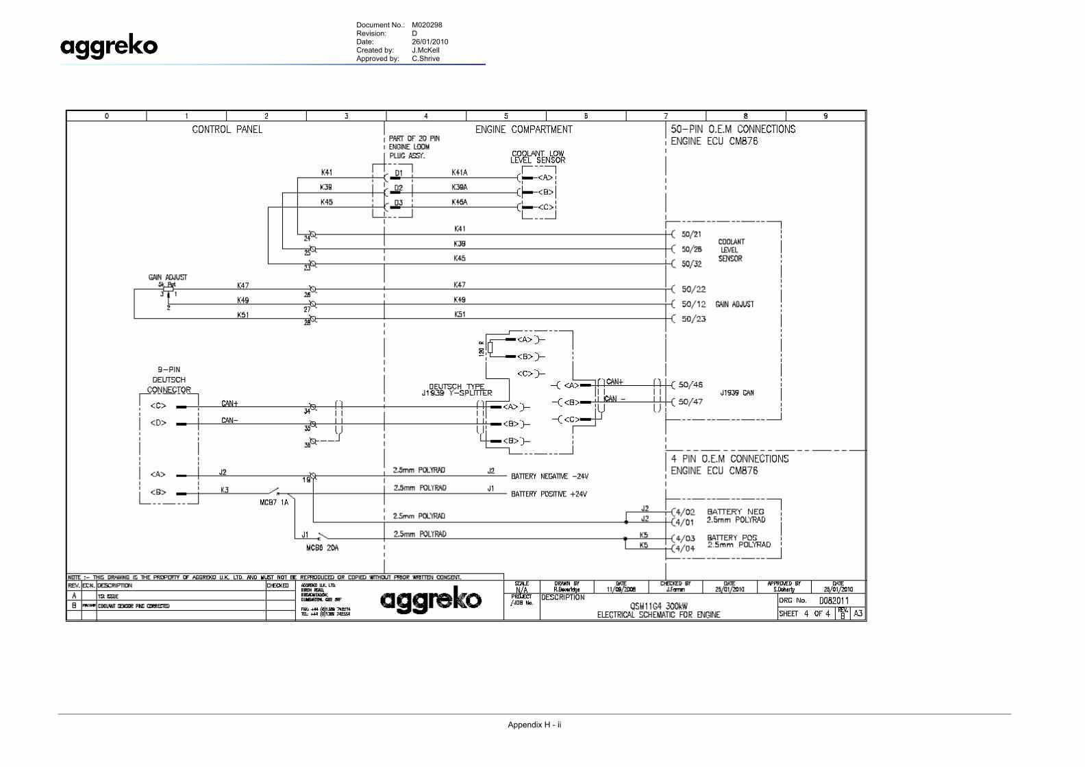
ELECTRICAL SCHEMATIC FOR ENGINE & CUMMINS ECM876
APP
END
IX H
Document No.: M020298 Revision: D Date: 26/01/2010 Created by: J.McKell Approved by: C.Shrive
Appendix H - ii
Document No.: M020298 Revision: D Date: 26/01/2010 Created by: J.McKell Approved by: C.Shrive
Appendix J - i
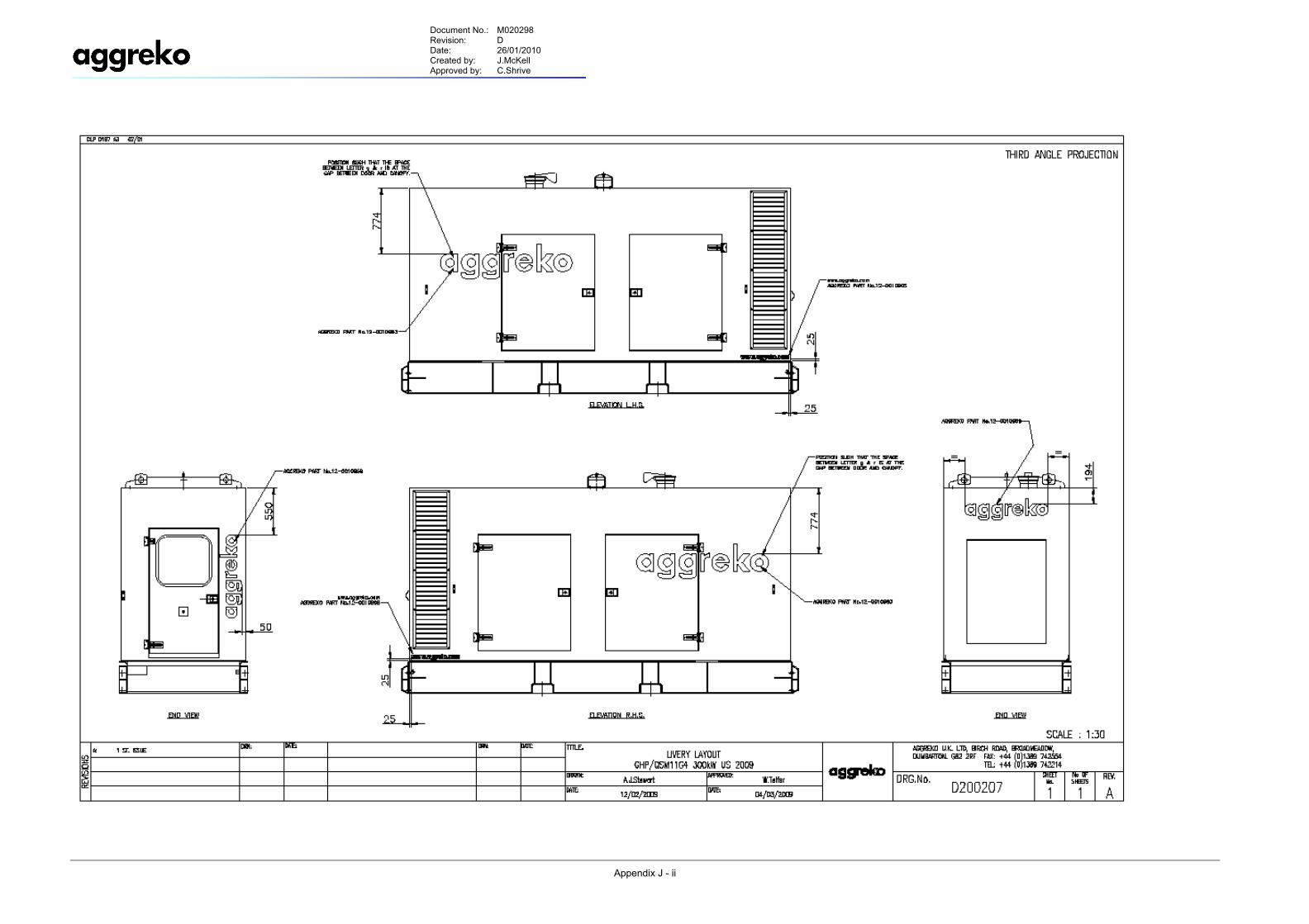
LIVERY LAYOUT
APP
END
IX J
Document No.: M020298 Revision: D Date: 26/01/2010 Created by: J.McKell Approved by: C.Shrive
Appendix J - ii
Document No.: M020298 Revision: D Date: 26/01/2010 Created by: J.McKell Approved by: C.Shrive
Appendix K - i
ENGINE WIRING & CONTROL PANEL TERMINALS
APP
END
IX K
Document No.: M020298 Revision: D Date: 26/01/2010 Created by: J.McKell Approved by: C.Shrive
Appendix K - ii
Document No.: M020298 Revision: D Date: 26/01/2010 Created by: J.McKell Approved by: C.Shrive
Appendix L - i
SPARES LIST & MANUFACTURERS DATA
APP
END
IX L
Document No.: M020298 Revision: D Date: 26/01/2010 Created by: J.McKell Approved by: C.Shrive
Appendix L - ii

Document No.: M020298 Revision: D Date: 26/01/2010 Created by: J.McKell Approved by: C.Shrive
Appendix M - i
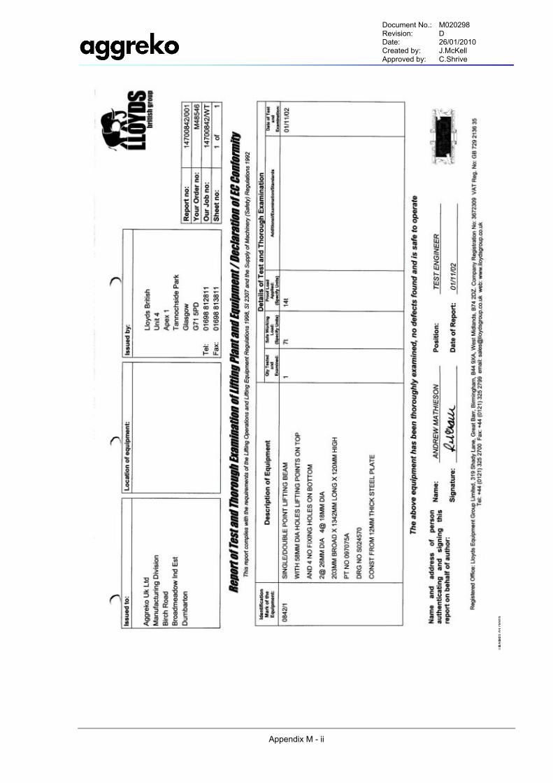
LIFTING BEAM CERTIFICATE
APP
END
IX M
Document No.: M020298 Revision: D Date: 26/01/2010 Created by: J.McKell Approved by: C.Shrive
Appendix M - ii
Document No.: M020298 Revision: D Date: 26/01/2010 Created by: J.McKell Approved by: C.Shrive
Appendix N - i
DNV SPARK ARRESTOR CERTIFICATE
APP
END
IX N
Document No.: M020298 Revision: D Date: 26/01/2010 Created by: J.McKell Approved by: C.Shrive
Appendix N - ii
Document No.: M020298 Revision: D Date: 26/01/2010 Created by: J.McKell Approved by: C.Shrive
Appendix N - iii

Document No.: M020298 Revision: D Date: 26/01/2010 Created by: J.McKell Approved by: C.Shrive
Appendix P - i
INTERNATIONAL CONTACT INFORMATION
APP
END
IX P
Document No.: M020298 Revision: D Date: 26/01/2010 Created by: J.McKell Approved by: C.Shrive
Appendix P - ii
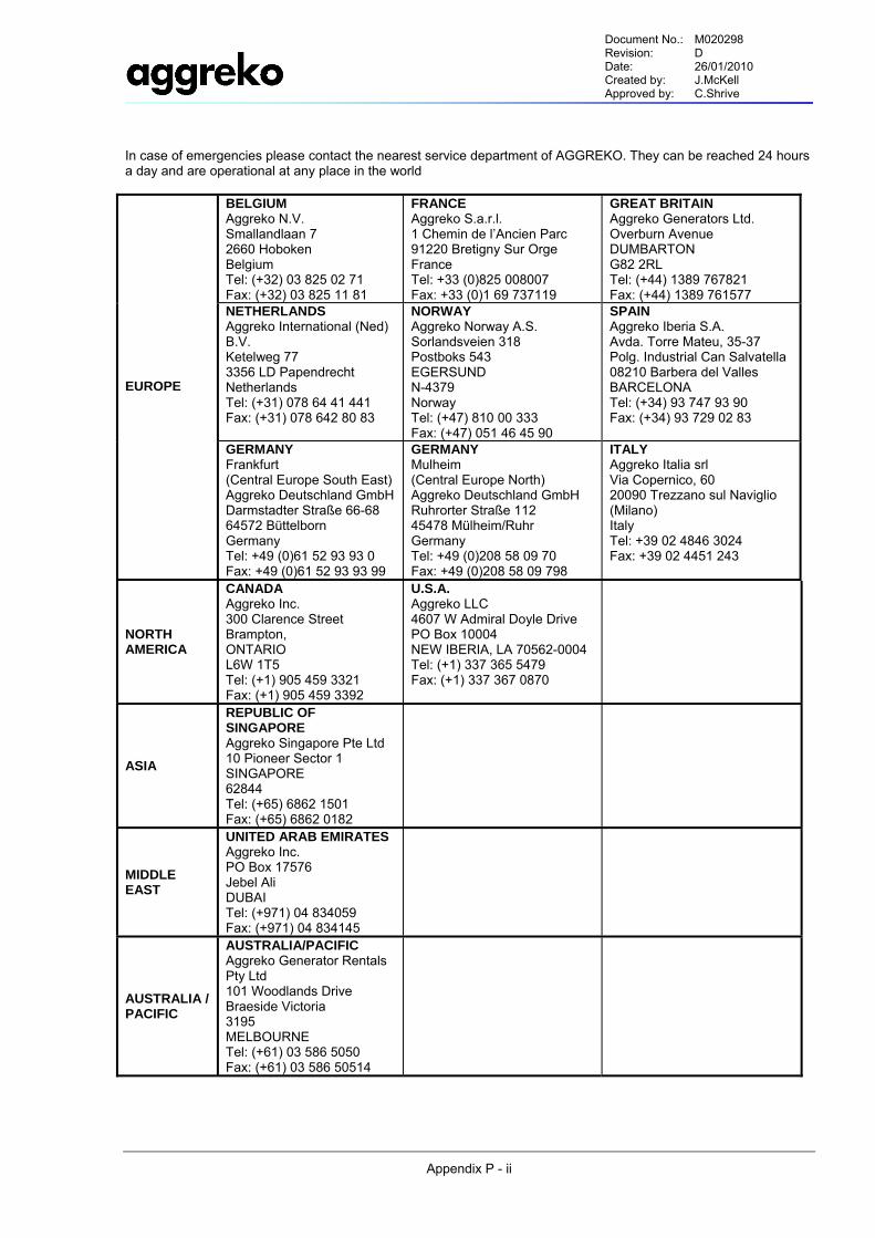
In case of emergencies please contact the nearest service department of AGGREKO. They can be reached 24 hours a day and are operational at any place in the world
BELGIUM Aggreko N.V. Smallandlaan 7 2660 Hoboken Belgium Tel: (+32) 03 825 02 71 Fax: (+32) 03 825 11 81
FRANCE Aggreko S.a.r.l. 1 Chemin de l’Ancien Parc 91220 Bretigny Sur Orge France Tel: +33 (0)825 008007 Fax: +33 (0)1 69 737119
GREAT BRITAIN Aggreko Generators Ltd. Overburn Avenue DUMBARTON G82 2RL Tel: (+44) 1389 767821 Fax: (+44) 1389 761577
NETHERLANDS Aggreko International (Ned) B.V. Ketelweg 77 3356 LD Papendrecht Netherlands Tel: (+31) 078 64 41 441 Fax: (+31) 078 642 80 83
NORWAY Aggreko Norway A.S. Sorlandsveien 318 Postboks 543 EGERSUND N-4379 Norway Tel: (+47) 810 00 333 Fax: (+47) 051 46 45 90
SPAIN Aggreko Iberia S.A. Avda. Torre Mateu, 35-37 Polg. Industrial Can Salvatella 08210 Barbera del Valles BARCELONA Tel: (+34) 93 747 93 90 Fax: (+34) 93 729 02 83
EUROPE
GERMANY Frankfurt (Central Europe South East) Aggreko Deutschland GmbHDarmstadter Straße 66-68 64572 Büttelborn Germany Tel: +49 (0)61 52 93 93 0 Fax: +49 (0)61 52 93 93 99
GERMANY Mulheim (Central Europe North) Aggreko Deutschland GmbH Ruhrorter Straße 112 45478 Mülheim/Ruhr Germany Tel: +49 (0)208 58 09 70 Fax: +49 (0)208 58 09 798
ITALY Aggreko Italia srl Via Copernico, 60 20090 Trezzano sul Naviglio (Milano) Italy Tel: +39 02 4846 3024 Fax: +39 02 4451 243
NORTH AMERICA
CANADA Aggreko Inc. 300 Clarence Street Brampton, ONTARIO L6W 1T5 Tel: (+1) 905 459 3321 Fax: (+1) 905 459 3392
U.S.A. Aggreko LLC 4607 W Admiral Doyle Drive PO Box 10004 NEW IBERIA, LA 70562-0004 Tel: (+1) 337 365 5479 Fax: (+1) 337 367 0870
ASIA
REPUBLIC OF SINGAPORE Aggreko Singapore Pte Ltd 10 Pioneer Sector 1 SINGAPORE 62844 Tel: (+65) 6862 1501 Fax: (+65) 6862 0182
MIDDLE EAST
UNITED ARAB EMIRATES Aggreko Inc. PO Box 17576 Jebel Ali DUBAI Tel: (+971) 04 834059 Fax: (+971) 04 834145
AUSTRALIA / PACIFIC
AUSTRALIA/PACIFIC Aggreko Generator Rentals Pty Ltd 101 Woodlands Drive Braeside Victoria 3195 MELBOURNE Tel: (+61) 03 586 5050 Fax: (+61) 03 586 50514