Embed Size (px)
Citation preview

PCT100i Operation Manual
1
PONOVO POWER CO., LTD
2F, 4Cell, Tower C, In.Do Mansion
No.48A Zhichun Road, Haidian District
Beijing, China (Post Code 100098)
Office TEL. +86 (10) 82755151 ext. 8887
FAX +86 (10) 82755257
E-Mail [email protected]
Website www.ponovo.com.cn
PCT100I
OPERATION MANUAL
VERSION: PCT100I-AE-1.10
DATE: 14/07/2011
This manual is the publication of PONOVO POWER CO., LTD. Any form of copy should obtain the
consent of it.
This manual represents the technical status for the moment of publishing. The product information,
description and specifications mentioned in the manual do not have any contact binding force and
PONOVO POWER CO., LTD remains the right to make modifications to the technical
specifications and configurations without prior notice. PONOVO POWER does not take
responsibility to the possible error/mistakes in this manual.

PCT100i Operation Manual
2
Content
1. General Description ....................................................................................................... 5
1.1 Functions .............................................................................................................. 5
1.2 Features ............................................................................................................... 5
1.3 Operation Preparation .......................................................................................... 6
2. Panel Description ........................................................................................................... 8
3. Technical Specification ................................................................................................... 9
3.1 Output and Input ................................................................................................... 9
3.2 Main Supply .......................................................................................................... 9
3.3 Environment Conditions ........................................................................................ 9
3.4 Dimension and Weight ........................................................................................ 10
4. Operation Instruction ................................................................................................... 11
4.1 Select Test Functions .......................................................................................... 11
4.2 Set Test Parameters ........................................................................................... 11
4.3 Control Output .................................................................................................... 12
4.4 Save Test Report ................................................................................................ 12
5. Burden Test .................................................................................................................. 14
5.1 Wiring Connection .............................................................................................. 14
5.2 Test Operation .................................................................................................... 15
6. CT Test ........................................................................................................................ 16
6.1 Wiring Connection .............................................................................................. 16
6.2 Test Operation .................................................................................................... 17
6.2.1 Settings .................................................................................................... 17
6.2.2 Rct Measuring .......................................................................................... 18
6.2.3 Demagnetization ....................................................................................... 19
6.2.4 Polarity Check .......................................................................................... 20
6.2.5 Excitation Test .......................................................................................... 21
6.2.6 Ratio Test .................................................................................................. 25
6.2.7 Auto Test ................................................................................................... 26
6.3 Application Examples.......................................................................................... 27

PCT100i Operation Manual
3
6.3.1 Transmission line CT Test ......................................................................... 27
6.3.2 CT Test in Y Voltage Transformer ............................................................. 28
6.3.3 CT Test in the Star Connection Voltage Transformer ................................ 29
6.3.4 Bushing CT Test ....................................................................................... 30
6.3.5 Test CT with Tapping ................................................................................ 31
7. PT test ......................................................................................................................... 32
7.1 Wiring Connection .............................................................................................. 32
7.1.1 Polarity and Ratio Test .............................................................................. 32
7.1.2 Excitation Test .......................................................................................... 34
7.2 Test Operation .................................................................................................... 35
7.2.1 Settings .................................................................................................... 35
7.2.2 Polarity and Ratio Test .............................................................................. 35
7.2.3 Excitation Test .......................................................................................... 36

PCT100i Operation Manual
4
Notes:
In order to prevent static electricity, the tester must be connected to ground
before testing.
Avoid electric shock accident when the output voltage is above 36V.
Short circuit is prohibited at output side while testing.
Connect wires in accordance with instructions.
External voltages and currents are prohibited to apply on the tester’s output.
Avoid the equipment being wet by rain.
Contact manufacturer timely and do not repair it when device works abnormally.

PCT100i Operation Manual
5
1. General Description
1.1 Functions
CT testing:
Secondary side burden test
Secondary side winding resistance test
Excitation test with automatic calculation of knee point
Polarity test
Ratio test
Ratio and angular difference at rated load
Demagnetization
PT Testing:
Polarity test
Ratio test
Excitation test
1.2 Features
Testing CT by voltage method
Based on frequency test principle and can test knee point voltage up to 20kV
Requiring low output voltage and power. Portable design with small size and lightweight
Whole machine integration design, adopting anti-vibration and anti-electromagnetic
interference combination chassis.
Embedded microprocessor digital platform without external PC, easy to operate and

PCT100i Operation Manual
6
finishing automatic testing in a few seconds.
Testing results can be led out by U disk.
Internal linear amplifier, fast response time, high precision and reliability. With maximum
output AC voltage 120V, maximum output current 5 Arms.
1.3 Operation Preparation
Preparation:
CT secondary side load loop disconnection and secondary winding off-grounded
CT primary side disconnects with busbar
Order of connection:

PCT100i Operation Manual
7
Utility line
Burden
1
2
3
4
5
6
1. The chassis of PCT is grounded.
2. One end of CT primary side grounded (P2)
Note: There is a grounding switch in one side of primary. No matter the grounding switch is in P1
or P2, only one end is supposed to ground.
3. The test lead connects with P1, P2 of CT.
4. The other end of the lead connects with P1, P2 of PCT100i.
5. One secondary side connects with one group of CT’s S1 and S2
6. The other Secondary side connects with S1, S2 of PCT100i.
7. Power on

PCT100i Operation Manual
8
2. Panel Description
1) Connecting CT secondary side
2) Secondary side voltage test while testing CT
3) Primary side voltage test while testing CT
4) Connecting PT primary side
5) Secondary side voltage test while testing PT
6) Run lamp: output indicator--flashing while outputting
Stop lamp: indicating output stop--flashing without output
7) Rotary encoder: selecting menu and setting specifications
8) USB interface: lead-out report by U disk
9) Instrument chassis ground terminal
10) Power switch
11) Function control button
12) LCD display

PCT100i Operation Manual
9
3. Technical Specification
3.1 Output and Input
Voltage output range: 0~120V
Current output range: 0~5Arms
Max. ratio: 30,000:1 ,45,000:5
Accuracy: ±0.2%
Max. Knee point voltage: 20KV
Secondary burden measuring range: 0.1Ω~100Ω
Secondary burden measuring accuracy: 0.2%±1mΩ
Secondary winding resistance measuring range: 0.1Ω~100Ω
Secondary winding resistance measuring accuracy: 0.2%±1mΩ
Current measuring accuracy: 0.2%+0.2mA
Voltage measuring accuracy: 0.2%+0.2mV
3.2 Main Supply
Input voltage: 110/240 VAC,50/60HZ
3.3 Environment Conditions
Operation temperature: -10~50
Operation humidity:≤90%, non-condensing

PCT100i Operation Manual
10
3.4 Dimension and Weight
Aluminum alloy extrusion, EMC enclosure chassis:320mm x364mm x 155(W*H*L)
Weight: 11Kg
PCT100i Operation Manual
11
4. Operation Instruction
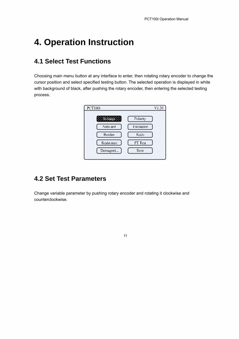
4.1 Select Test Functions
Choosing main menu button at any interface to enter, then rotating rotary encoder to change the
cursor position and select specified testing button. The selected operation is displayed in white
with background of black, after pushing the rotary encoder, then entering the selected testing
process.
4.2 Set Test Parameters
Change variable parameter by pushing rotary encoder and rotating it clockwise and
counterclockwise.

PCT100i Operation Manual
12
4.3 Control Output
Pushing run and stop buttons can control the functions of output and stop output. While output,
the operation indicator will flash.
4.4 Save Test Report
After testing, a U disk should be inserted through the USB interface, selecting the save key,
pushing rotary encoder to save test report which is saved as TXT format. The following picture
indicates the save is in process, and the U disk cannot be pulled out. When the cursor moves
automatically from save unit to parameter setting, the save process is finished and the U disk can
be extracted.
Notes: Please use the distributed U disk while saving the results.
Other profiles are not permit in the U disk while saving the report. Otherwise, there will be
some mistakes or other profiles will be damaged.

PCT100i Operation Manual
13
While pushing rotary encoder to save test report, if it displays like the following picture, the U disk
should be inserted once again or be changed a new one.

PCT100i Operation Manual
14
5. Burden Test
5.1 Wiring Connection
Connecting the instrument transformer according to the below direction, while doing secondary
load impedance test.
Wiring direction: The instrument transformer’s output end S1 and testing end S1 are connected
with the secondary load side of the CT.
The instrument transformer’s output end S2 and testing end S2 are connected
with the other side of secondary load of the CT.

PCT100i Operation Manual
15
5.2 Test Operation
Entering the main menu and selecting the burden measuring unit, CT secondary burden
measuring can be done. After entering burden measuring unit, the process can automatically run
after pushing the button. The testing result is displayed in Z zone. It stops automatically and the
lamp turns off.

PCT100i Operation Manual
16
6. CT Test
6.1 Wiring Connection
While doing the CT secondary coil resistance, polarity, excitation demagnetization and ratio test,
The instrument transformer tester should be connected according to the below diagram.
Wiring direction: The instrument transformer’s output side S1 and testing side S1 are
connected with the secondary side of the CT.
The instrument transformer’s output side S2 and testing side S2 are
connected with the other side of secondary side of the CT.
The instrument transformer’s primary test side P1 is connected with one
side of the CT primary test.
The instrument transformer’s primary test end P2 is connected with the
other side of the CT primary test.

PCT100i Operation Manual
17
6.2 Test Operation
6.2.1 Settings
The CT parameters are set by rotary encoder properly; otherwise, the test results are not correct.
f: rated frequency; VA: rated capacity; COSφ: power factor; P/TP: the CT type; I-sn: secondary
side rated current; I-pn: primary side rated current; Substation: name of substation; Standard: test
standard based on; Winding: the number of the winding; SN: the serial number of the winding;
Date: date of test.

PCT100i Operation Manual
18
6.2.2 Rct Measuring
CT secondary winding resistance test can be done after selecting the Rct measuring unit.
Entering the Rct measuring unit, the temperature of rotary encoder is present test temperature.
The secondary side winding resistance test will automatically run after pushing the run button. The
test results display at R. R75 is the resistance at 75. After testing, it stops automatically and
the lamp is off.

PCT100i Operation Manual
19
6.2.3 Demagnetization
CT demagnetization can be done after selecting the demagnetization unit. The process will
automatically run when entering the unit and pushing the run button. After the process, it will
automatically stop and the lamp is off.

PCT100i Operation Manual
20
6.2.4 Polarity Check
CT polarity check can be done after selecting the polarity check unit. The polarity check is
automatically finished while pushing the run button. It stops automatically and the lamp is off. The
test method is negative polar.

PCT100i Operation Manual
21
6.2.5 Excitation Test
CT excitation test can be done after selecting the excitation unit.
The test will automatically run while entering the excitation unit. It stops automatically after test
and the lamp is off.
The test result displays in curve, and the voltage and current are shown at knee point. Pushing
rotary encoder will go back to the top.

PCT100i Operation Manual
22
After excitation curve test, V-A data should be selected.
Every voltage and current can be checked while entering the V-A data. The voltage and current
are displayed at lower right corner in the diagram.

PCT100i Operation Manual
23
Select “3” through rotary encoder as illustrated in the below diagram.
Push rotary encoder and enter the below interface. Any 10 sets of excitation data can be checked
in the unit.

PCT100i Operation Manual
24
The excitation current can be changed by moving cursor to any set of excitation current and
the relative excitation voltage is automatically displayed. The step can be also changed
according to “coarse/fine”. The coarse step is 0.1A, and the fine step is 0.001A.
>
After setting the excitation current, moving cursor to “ ” and pushing rotary button, the 10 sets excitation current values are automatically saved in the FLASH, and they will be led out
automatically next power-on.

PCT100i Operation Manual
25
6.2.6 Ratio Test
Firstly do RCT test to make sure the angular difference before doing CT ratio.
The angular difference and ratio show the error at rated load.
CT ratio test can be done after selecting the ratio test unit and pushing run button. When the test
is completed, it stops automatically and the lamp is off.
PCT100i Operation Manual
26
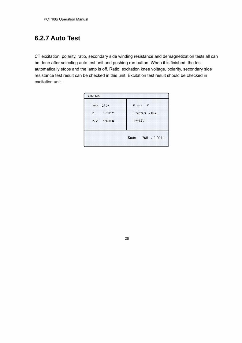
6.2.7 Auto Test
CT excitation, polarity, ratio, secondary side winding resistance and demagnetization tests all can
be done after selecting auto test unit and pushing run button. When it is finished, the test
automatically stops and the lamp is off. Ratio, excitation knee voltage, polarity, secondary side
resistance test result can be checked in this unit. Excitation test result should be checked in
excitation unit.

PCT100i Operation Manual
27
6.3 Application Examples
6.3.1 Transmission line CT Test

PCT100i Operation Manual
28
6.3.2 CT Test in Y Voltage Transformer
In order to reduce interference, other windings of the CT voltage transformer should be short
circuit.

PCT100i Operation Manual
29
6.3.3 CT Test in the Star Connection Voltage Transformer
In order to reduce interference, other voltage transformer’s windings should be short circuit.

PCT100i Operation Manual
30
6.3.4 Bushing CT Test In order to reduce interference, other windings of the CT voltage transformer should be short
circuit.

PCT100i Operation Manual
31
6.3.5 Test CT with Tapping
All the windings in the same shank are all switched on while testing CT with tapping.

PCT100i Operation Manual
32
7. PT test
7.1 Wiring Connection
7.1.1 Polarity and Ratio Test
Connect instrument transformer tester as illustrated in below when doing PT polarity, ratio test.

PCT100i Operation Manual
33
Wiring directions:The output A of transformer is connected with one side of PT primary.
The output N of transformer is connected with one side of PT primary.
The secondary testing end “a” of transformer is connected with one side of
PT secondary.
The secondary testing end “n” of transformer is connected with
the other end of PT secondary.
Note: The wiring for primary and secondary cannot be wrong, otherwise, it may give thousands of
voltage.

PCT100i Operation Manual
34
7.1.2 Excitation Test
Connect transformer tester as illustrated in below when doing PT excitation test.
Single-phase voltage transformer
Three-phase voltage transformer
Wiring directions: The output S1 of transformer is connected with one side of PT secondary.
The output S1 of transformer is connected with the other side of PT
secondary.
PT primary end is connected with a reliable ground, and other windings are
open circuit.
Notes: Keep off the instrument, in case that thousands of voltage may occur while doing
excitation test.

PCT100i Operation Manual
35
7.2 Test Operation
7.2.1 Settings
U-an is rated voltage of secondary and is set as PT secondary rated voltage.
7.2.2 Polarity and Ratio Test
The PT polarity, ratio test can be automatically finished after selecting polarity ratio and pushing
run button. It stops automatically and the lamp is off.

PCT100i Operation Manual
36
7.2.3 Excitation Test
Select PT test unit, and then choose excitation test.
PT excitation is finished automatically when selecting V-A Curve and pushing rotary button. It
stops automatically and the lamp is off.
After testing excitation curve, every voltage and current on the excitation curve can be checked in
V-A Data.