Embed Size (px)
Citation preview
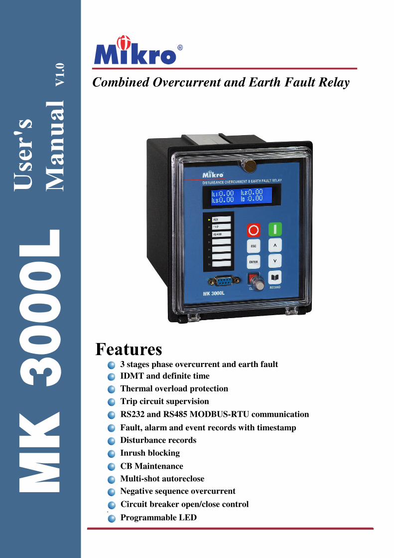
MK 3000L
V1.0
Combined Overcurrent and Earth Fault Relay
3 stages phase overcurrent and earth fault
IDMT and definite time
Thermal overload protection
Fault, alarm and event records with timestamp
Disturbance records
CB Maintenance
Multi-shot autoreclose
Trip circuit supervision
RS232 and RS485 MODBUS-RTU communication
Negative sequence overcurrent
Circuit breaker open/close control
Programmable LED
Inrush blocking

2
Table of Contents
1.0 Introduction ........................................................................................................... 3
1.1 Symbols and Definitions ............................................................................................................ 3
1.2 Main Functions .......................................................................................................................... 4
2.0 Front Panel ............................................................................................................. 5
2.1 LCD Display .............................................................................................................................. 5
2.2 Keypad ....................................................................................................................................... 5
2.3 LEDs .......................................................................................................................................... 6
2.4 RS232 Port ................................................................................................................................. 6
2.5 Default Display .......................................................................................................................... 6
2.6 Alarm Condition ......................................................................................................................... 6
2.6.1 Alarm Auto Scrolling .............................................................................................................. 6
3.0 Password ................................................................................................................. 7
3.1 Password Protection ................................................................................................................... 7
3.2 Password Entry .......................................................................................................................... 7
3.3 Changing Password .................................................................................................................... 7
4.0 Menus...................................................................................................................... 7
4.1 Menu Contents ........................................................................................................................... 7
MEASUREMENTS Menu ............................................................................................................... 9
RECORDS Menu ........................................................................................................................... 12
CONFIGURATION Menu ............................................................................................................. 14
PROTECTION G1 Menu .............................................................................................................. 17
PROTECTION G2 Menu .............................................................................................................. 22
INPUT Menu.................................................................................................................................. 22
OUTPUT Menu.............................................................................................................................. 24
COMMUNICATION Menu ........................................................................................................... 26
MISC CONTROL Menu ................................................................................................................ 27
5.0 Functions and Descriptions ................................................................................ 31
5.1 Circuit Breaker Failure Protection ........................................................................................... 31
5.2 Inrush Blocking ........................................................................................................................ 31
5.3 Thermal Overload Protection ................................................................................................... 32
5.4 Trip Circuit Supervision ........................................................................................................... 33
5.5 Disturbance Recorder ............................................................................................................... 35
5.6 Autoreclose .............................................................................................................................. 35
5.7 Open CB & Close CB Control ................................................................................................. 36
5.8 Characteristic Curves ............................................................................................................... 37
6.0 Case Dimensions .................................................................................................. 39
7.0 Connection Diagram and Terminal ................................................................... 39
7.1 Terminal Connection at Rear View .......................................................................................... 39
7.2 Typical Connection Diagram ................................................................................................... 41
8.0 Technical Data ...................................................................................................... 42
9.0 MODBUS Protocol .............................................................................................. 47
9.1 MODBUS Functions ................................................................................................................ 47
9.2 MODBUS Register .................................................................................................................. 49
9.3 MODBUS Mapping Format .................................................................................................... 57
3
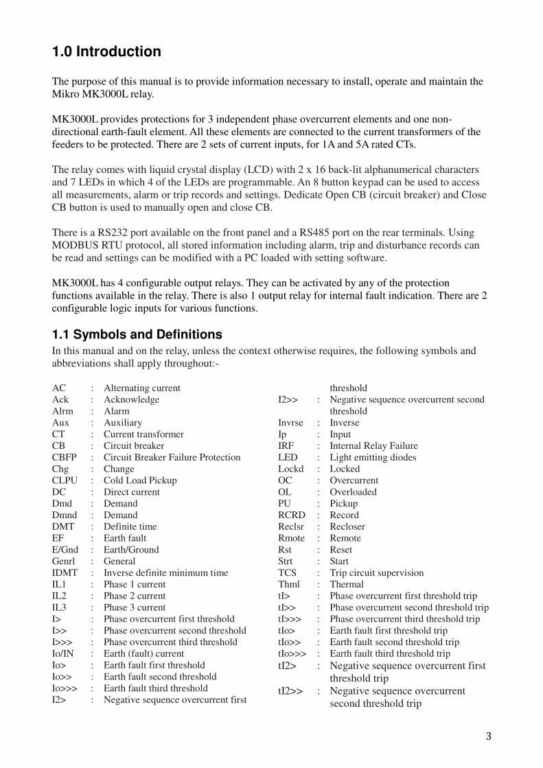
1.0 Introduction
The purpose of this manual is to provide information necessary to install, operate and maintain the
Mikro MK3000L relay.
MK3000L provides protections for 3 independent phase overcurrent elements and one non-
directional earth-fault element. All these elements are connected to the current transformers of the
feeders to be protected. There are 2 sets of current inputs, for 1A and 5A rated CTs.
The relay comes with liquid crystal display (LCD) with 2 x 16 back-lit alphanumerical characters
and 7 LEDs in which 4 of the LEDs are programmable. An 8 button keypad can be used to access
all measurements, alarm or trip records and settings. Dedicate Open CB (circuit breaker) and Close
CB button is used to manually open and close CB.
There is a RS232 port available on the front panel and a RS485 port on the rear terminals. Using
MODBUS RTU protocol, all stored information including alarm, trip and disturbance records can
be read and settings can be modified with a PC loaded with setting software.
MK3000L has 4 configurable output relays. They can be activated by any of the protection
functions available in the relay. There is also 1 output relay for internal fault indication. There are 2
configurable logic inputs for various functions.
1.1 Symbols and Definitions
In this manual and on the relay, unless the context otherwise requires, the following symbols and
abbreviations shall apply throughout:-
AC : Alternating current
Ack : Acknowledge
Alrm : Alarm
Aux : Auxiliary
CT : Current transformer
CB : Circuit breaker
CBFP : Circuit Breaker Failure Protection
Chg : Change
CLPU : Cold Load Pickup
DC : Direct current
Dmd : Demand
Dmnd : Demand
DMT : Definite time
EF : Earth fault
E/Gnd : Earth/Ground
Genrl : General
IDMT : Inverse definite minimum time
IL1 : Phase 1 current
IL2 : Phase 2 current
IL3 : Phase 3 current
I> : Phase overcurrent first threshold
I>> : Phase overcurrent second threshold
I>>> : Phase overcurrent third threshold
Io/IN : Earth (fault) current
Io> : Earth fault first threshold
Io>> : Earth fault second threshold
Io>>> : Earth fault third threshold
I2> : Negative sequence overcurrent first
threshold
I2>> : Negative sequence overcurrent second
threshold
Invrse : Inverse
Ip : Input
IRF : Internal Relay Failure
LED : Light emitting diodes
Lockd : Locked
OC : Overcurrent
OL : Overloaded
PU : Pickup
RCRD : Record
Reclsr : Recloser
Rmote : Remote
Rst : Reset
Strt : Start
TCS : Trip circuit supervision
Thml : Thermal
tI> : Phase overcurrent first threshold trip
tI>> : Phase overcurrent second threshold trip
tI>>> : Phase overcurrent third threshold trip
tIo> : Earth fault first threshold trip
tIo>> : Earth fault second threshold trip
tIo>>> : Earth fault third threshold trip
tI2> : Negative sequence overcurrent first
threshold trip
tI2>> : Negative sequence overcurrent
second threshold trip
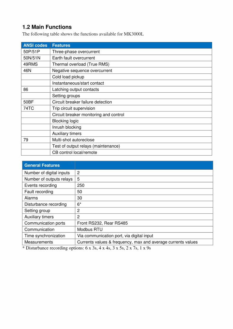
1.2 Main Functions
The following table shows the functions available for MK3000L
ANSI codes Features
50P/51P Three-phase overcurrent
50N/51N Earth fault overcurrent
49RMS Thermal overload (True RMS)
46N Negative sequence overcurrent
Cold load pickup
Instantaneous/start contact
86 Latching output contacts
Setting groups
50BF Circuit breaker failure detection
74TC Trip circuit supervision
Circuit breaker monitoring and control
Blocking logic
Inrush blocking
Auxiliary timers
79 Multi-shot autoreclose
Test of output relays (maintenance)
CB control local/remote
General Features
Number of digital inputs 2
Number of outputs relays 5
Events recording 250
Fault recording 50
Alarms 30
Disturbance recording 6*
Setting group 2
Auxiliary timers 2
Communication ports Front RS232, Rear RS485
Communication Modbus RTU
Time synchronization Via communication port, via digital input
Measurements Currents values & frequency, max and average currents values
* Disturbance recording options: 6 x 3s, 4 x 4s, 3 x 5s, 2 x 7s, 1 x 9s
5
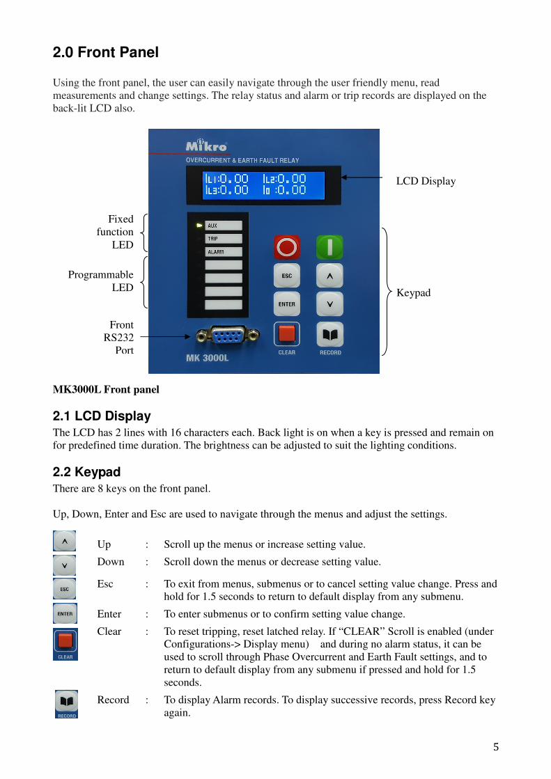
2.0 Front Panel
Using the front panel, the user can easily navigate through the user friendly menu, read
measurements and change settings. The relay status and alarm or trip records are displayed on the
back-lit LCD also.
MK3000L Front panel
2.1 LCD Display
The LCD has 2 lines with 16 characters each. Back light is on when a key is pressed and remain on
for predefined time duration. The brightness can be adjusted to suit the lighting conditions.
2.2 Keypad
There are 8 keys on the front panel.
Up, Down, Enter and Esc are used to navigate through the menus and adjust the settings.
Up : Scroll up the menus or increase setting value.
Down : Scroll down the menus or decrease setting value.
Esc : To exit from menus, submenus or to cancel setting value change. Press and
hold for 1.5 seconds to return to default display from any submenu.
Enter : To enter submenus or to confirm setting value change.
Clear : To reset tripping, reset latched relay. If “CLEAR” Scroll is enabled (under
Configurations-> Display menu) and during no alarm status, it can be
used to scroll through Phase Overcurrent and Earth Fault settings, and to
return to default display from any submenu if pressed and hold for 1.5
seconds.
Record : To display Alarm records. To display successive records, press Record key
again.
LCD Display
Keypad
Front
RS232
Port
Fixed
function
LED
Programmable
LED
6
Open CB : To open circuit breaker from front panel.
Close CB : To close circuit breaker from front panel.
2.3 LEDs
Aux LED : Indicates auxiliary power to the device
Trip LED : Indicates tripping.
Alarm LED : Blinks to indicate non acknowledge alarm (or tripping). Steady on when
the alarm is acknowledged by pressing any key
Programmable LED : 4 Programmable LED can be programmed to turn on when one or more
linked function trigger.
2.4 RS232 Port
The front panel RS232 port has the same MODBUS RTU protocol as the RS485 port on the rear
terminal, though with fixed communication settings: 38400bps, 1 stop bit, even parity, address 1.
All stored information can be read and settings can be modified with a PC loaded with the supplied
setting software.
2.5 Default Display
By default the LCD displays the current value measured for IL1, IL2, IL3 and Io. Input and output
status as well as date and time can be shown by pressing Up key or Down key to change the default
display page. Pressing Esc key always return to current value display.
As soon as an alarm or trip is detected, the display jumps to alarm record display to show the latest
record.
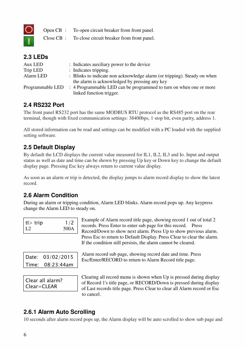
2.6 Alarm Condition
During an alarm or tripping condition, Alarm LED blinks. Alarm record pops up. Any keypress
change the Alarm LED to steady on.
Example of Alarm record title page, showing record 1 out of total 2
records. Press Enter to enter sub page for this record. Press
Record/Down to show next alarm. Press Up to show previous alarm.
Press Esc to return to Default Display. Press Clear to clear the alarm.
If the condition still persists, the alarm cannot be cleared.
Alarm record sub page, showing record date and time. Press
Esc/Enter/RECORD to return to Alarm Record title page.
Clearing all record menu is shown when Up is pressed during display
of Record 1's title page, or RECORD/Down is pressed during display
of Last records title page. Press Clear to clear all Alarm record or Esc
to cancel.
2.6.1 Alarm Auto Scrolling
10 seconds after alarm record pops up, the Alarm display will be auto scrolled to show sub page and
tI> trip 1/2 L2 500A
Date: 03/02/2015
Time: 08:23:44am
Clear all alarm? Clear=CLEAR
7
subsequently next records until all the records are shown and repeats. Each page is shown for 5
seconds. Example when there are 2 alarm records:
Record 1 Title Page � Record 1 Sub Page � Record 2 Title Page � Record 2 Sub Page � Record
1 Title Page � ….
Any key pressed stops auto scrolling. After 2 minutes of no activity, with which display still
showing the alarm record, auto scrolling starts again.
3.0 Password
3.1 Password Protection
Relay settings can be view anytime but locked from being changed. A password is required for
changing setting and CB Open, CB Close button pressed.
The password consists of four digit numbers. The factory default password is set as 0000.
The programming mode is indicated with the letter "P" on the right hand side of the display. The
letter "P" remains present as long as the password is active. (2 minutes if there is no key action).
3.2 Password Entry
The input of the password is requested as soon as a modification of a parameter is made or
Open/Close CB button is pressed. The user enters each one of the 4 digits by using up or down key
and validates each digit with Enter. If Esc is pressed in between, the password entering is
terminated.
“Password OK” is shown if correct password is entered. “Password ERROR” is shown if wrong
password is entered.
The display returns to the point of the preceding menu. Pressed Enter again to modify the setting.
If no key is pressed after 2 minutes, the settings are locked. A new password
request is associated with any subsequent setting change.
3.3 Changing Password
To change the password, go to Op Parameter -> Password menu. Enter current password to unlock,
after that the display shows current password. Press Enter again to enter the new password.
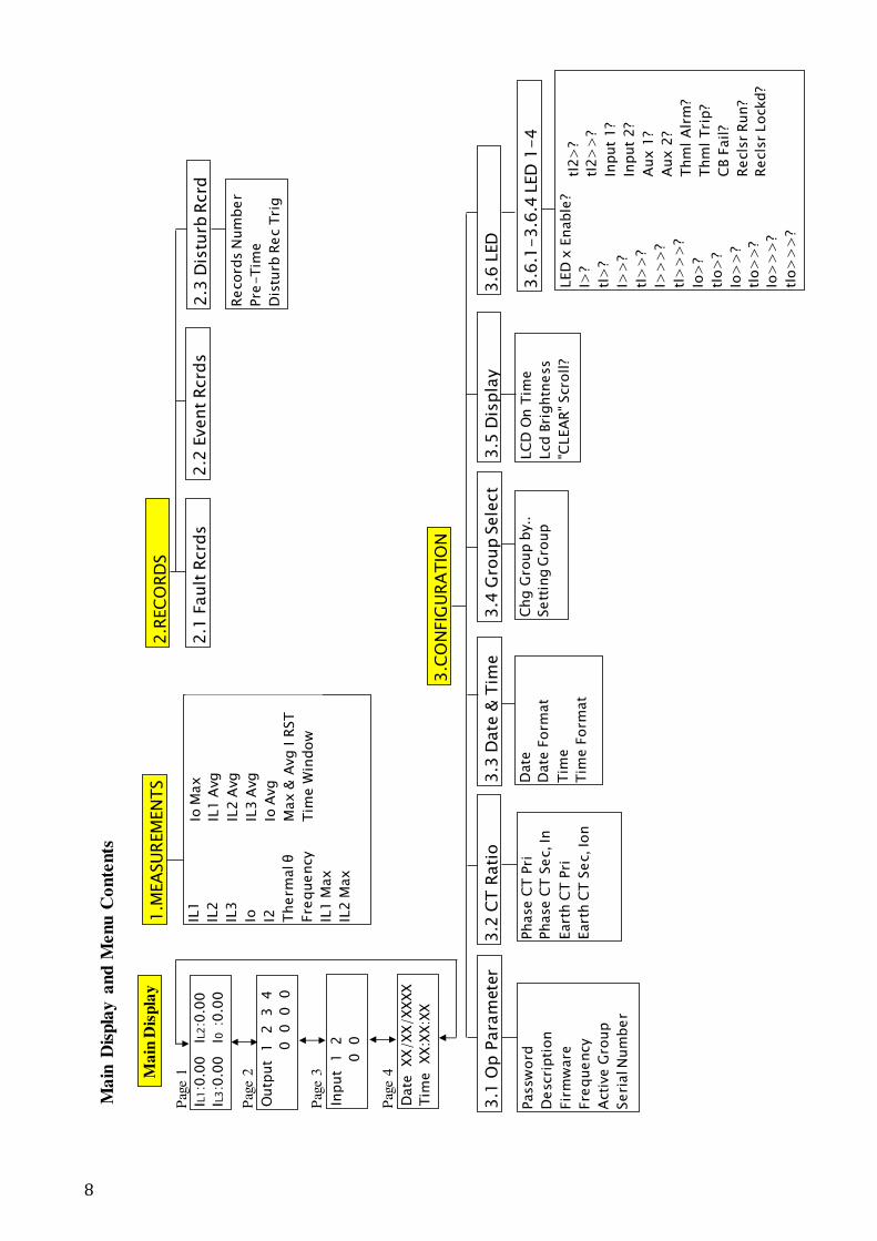
4.0 Menus The menu is divided into 9 main menus and their corresponding submenus. To enter Main menu,
press Enter during default display.
The menu can be navigated by pressing Up, Down, Enter and Esc keys. There is no need of a
password when reading settings and measured values.
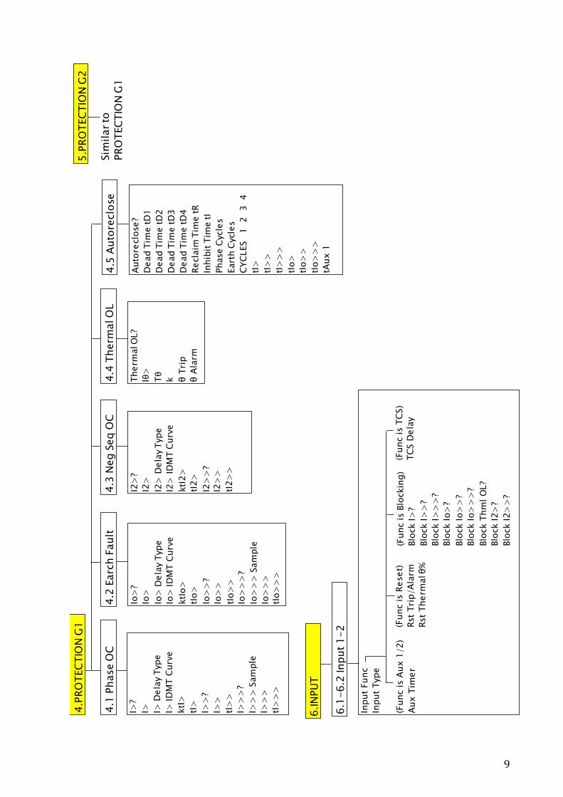
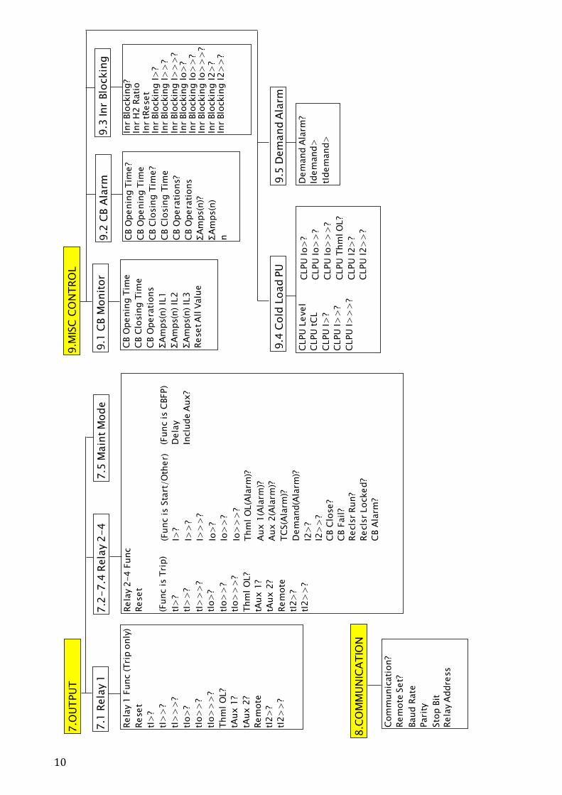
4.1 Menu Contents
The Main menu consists of 9 items. The menu structure is shown below:
8
LED
x E
nable
?
I>?
tI>
?
I>>
?
tI>
>?
I>>
>?
tI>
>>
?
Io>
?
tIo>
?
Io>
>?
tIo>
>?
Io>
>>
?
tIo>
>>
?
Ma
in D
isp
lay
Pag
e 1
Ma
in D
isp
lay a
nd
Men
u C
on
ten
ts
IL1:0
.00 I
L2:0
.00
IL3:0
.00 I
0 :0
.00
Pag
e 2
Outp
ut
1
2 3 4
0 0 0 0
Pag
e 3
Input
1 2
0 0
Pag
e 4
Date
XX/X
X/XXXX
Tim
e XX:X
X:X
X
1.M
EA
SU
REM
EN
TS
IL1
IL2
IL3
Io I2 Therm
al θ
Fre
quency
IL1 M
ax
IL2 M
ax
2.R
EC
ORD
S
2.1
Fau
lt R
crd
s2
.2 E
ven
t Rcrd
s2
.3 D
istu
rb R
crd
Record
s N
um
ber
Pre
-Tim
e
Dis
turb
Rec T
rig
3.C
ON
FIG
UR
ATIO
N
3.1
Op
Para
mete
r3
.2 C
T R
ati
o3
.3 D
ate
& T
ime
Date
Date
Form
at
Tim
e
Tim
e F
orm
at
Passw
ord
Descri
pti
on
Fir
mw
are
Fre
quency
Acti
ve G
roup
Seri
al N
um
ber
Phase C
T P
ri
Phase C
T S
ec,
In
Eart
h C
T P
ri
Eart
h C
T S
ec,
Ion
3.4
Gro
up
Sele
ct
Chg G
roup b
y..
Sett
ing G
roup
3.5
Dis
pla
y
LC
D O
n T
ime
Lcd B
rightn
ess
"CLEA
R" Scr
oll?
3.6
LED
3.6
.1-3.6
.4 L
ED
1-4
tI2>
?
tI2>
>?
Input
1?
Input
2?
Aux 1
?
Aux 2
?
Thm
l A
lrm
?
Thm
l Tri
p?
CB F
ail?
Recls
r Run?
Recls
r Lockd?
Io M
ax
IL1 A
vg
IL2 A
vg
IL3 A
vg
Io A
vg
Max &
Avg I R
ST
Tim
e W
indow
9
Input
Func
Input
Type
(Func is A
ux 1
/2)
Aux T
imer
4.P
RO
TEC
TIO
N G
1
4.1
Ph
ase O
C
I>?
I> I> D
ela
y Typ
e
I> ID
MT C
urv
e
ktI
>
tI>
I>>
?
I>>
tI>
>
I>>
>?
I>>
> S
am
ple
I>>
>
tI>
>>
4.2
Earc
h F
ault
Io>
?
Io>
Io>
Dela
y T
ype
Io>
ID
MT C
urv
e
ktI
o>
tIo>
Io>
>?
Io>
>
tIo>
>
Io>
>>
?
Io>
>>
Sam
ple
Io>
>>
tIo>
>>
4.3
Neg S
eq O
C
I2>
?
I2>
I2>
Dela
y T
ype
I2>
ID
MT C
urv
e
ktI
2>
tI2>
I2>
>?
I2>
>
tI2>
>
4.4
Therm
al O
L
Therm
al O
L?
Iθ>
Tθ
k θ T
rip
θ A
larm
5.P
RO
TEC
TIO
N G
2
Sim
ilar to
PRO
TEC
TIO
N G
14.5
Auto
reclo
se
Auto
recl
ose
?
Dead T
ime tD
1
Dead T
ime tD
2
Dead T
ime tD
3
Dead T
ime tD
4
Recl
aim
Tim
e tR
Inhib
it T
ime tI
Phase C
ycle
s
Eart
h C
ycl
es
CYC
LES 1
2
3 4
tI>
tI>
>
tI>
>>
tIo>
tIo>
>
tIo>
>>
tAux 1
6.IN
PU
T
6.1
-6.2
Input 1-2 (F
unc
is R
eset)
Rst
Tri
p/A
larm
Rst
Therm
al θ
%
(Func is
Blo
ckin
g)
Blo
ck I>
?
Blo
ck I>
>?
Blo
ck I>
>>
?
Blo
ck Io>
?
Blo
ck Io>
>?
Blo
ck Io>
>>
?
Blo
ck T
hm
l O
L?
Blo
ck I2>
?
Blo
ck I2>
>?
(Func is
TC
S)
TC
S D
ela
y
10
Rela
y 2
-4 F
unc
Reset
(Func is T
rip)
tI>
?
tI>
>?
tI>
>>
?
tIo>
?
tIo>
>?
tIo>
>>
?
Thm
l O
L?
tAux 1
?
tAux 2
?
Rem
ote
tI2>
?
tI2>
>?
7.O
UT
PU
T
7.1
Rela
y 1
(Func is S
tart
/O
ther)
I>?
I>>
?
I>>
>?
Io>
?
Io>
>?
Io>
>>
?
Thm
l O
L(A
larm
)?
Aux 1
(Ala
rm)?
Aux 2
(Ala
rm)?
TC
S(A
larm
)?
Dem
and(A
larm
)?
I2>
?
I2>
>?
CB C
lose?
CB F
ail?
Recls
r Run?
Recls
r Locked?
CB A
larm
?
(Func is C
BFP)
Dela
y
Inclu
de A
ux?
Rela
y 1
Func (Tri
p o
nly
)
Reset
tI>
?
tI>
>?
tI>
>>
?
tIo>
?
tIo>
>?
tIo>
>>
?
Thm
l O
L?
tAux 1
?
tAux 2
?
Rem
ote
tI2>
?
tI2>
>?
7.2
-7
.4 R
ela
y 2
-4
7.5
Main
t M
od
e
9.M
ISC
CO
NT
RO
L
9.1
CB M
on
itor
CB O
penin
g T
ime
CB C
losin
g T
ime
CB O
pera
tions
ΣA
mps(n
) IL
1
ΣA
mps(n
) IL
2
ΣA
mps(n
) IL
3
Reset A
ll V
alu
e
9.2
CB A
larm
CB O
penin
g T
ime?
CB O
penin
g T
ime
CB C
losin
g T
ime?
CB C
losin
g T
ime
CB O
pera
tions?
CB O
pera
tions
ΣA
mps(n
)?
ΣA
mps(n
)
n
8.C
OM
MU
NIC
ATIO
N
Com
munic
ati
on?
Rem
ote
Set?
Baud R
ate
Pari
ty
Sto
p B
it
Rela
y A
ddre
ss
9.3
Inr
Blo
ckin
g
Inr
Blo
ckin
g?
Inr
H2 R
ati
oIn
r tR
eset
Inr
Blo
ckin
g I>
?In
r Blo
ckin
g I>
>?
Inr
Blo
ckin
g I>
>>
?In
r Blo
ckin
g Io>
?In
r Blo
ckin
g Io>
>?
Inr
Blo
ckin
g Io>
>>
?In
r Blo
ckin
g I2>
?In
r Blo
ckin
g I2>
>?
CLPU
Level
CLPU
tC
L
CLPU
I>
?
CLPU
I>
>?
CLPU
I>
>>
?
CLPU
Io>
?
CLPU
Io>
>?
CLPU
Io>
>>
?
CLPU
Thm
l O
L?
CLPU
I2>
?
CLPU
I2>
>?
9.4
Co
ld L
oad P
U9
.5 D
em
and
Ala
rm
Dem
and A
larm
?
Idem
and>
tIdem
and>
11
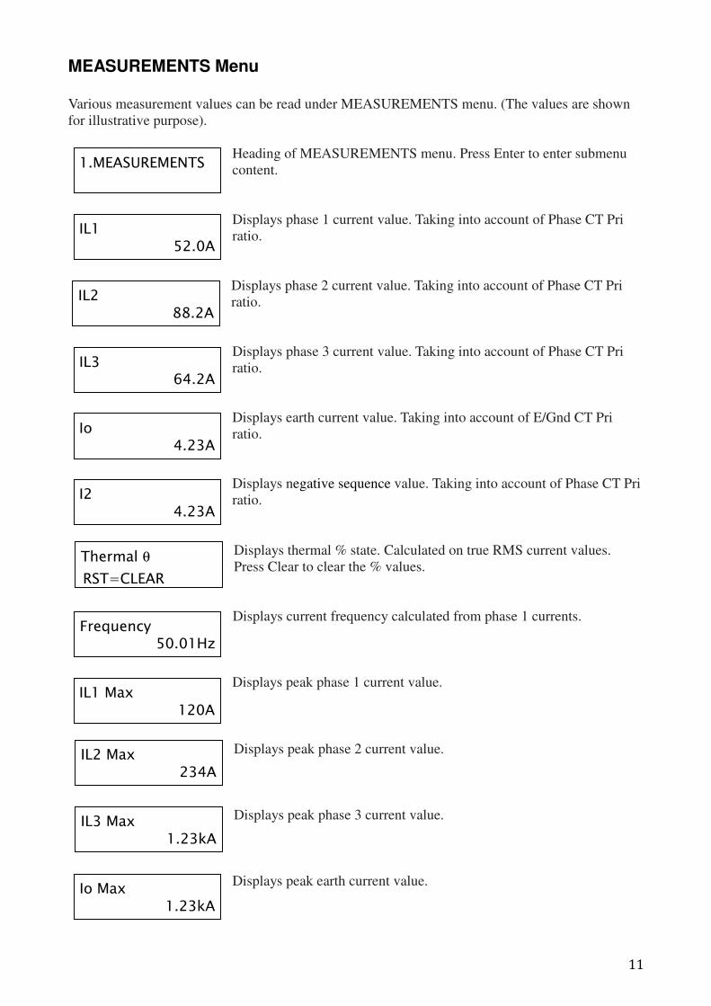
MEASUREMENTS Menu
Various measurement values can be read under MEASUREMENTS menu. (The values are shown
for illustrative purpose).
Heading of MEASUREMENTS menu. Press Enter to enter submenu
content.
Displays phase 1 current value. Taking into account of Phase CT Pri
ratio.
Displays phase 2 current value. Taking into account of Phase CT Pri
ratio.
Displays phase 3 current value. Taking into account of Phase CT Pri
ratio.
Displays earth current value. Taking into account of E/Gnd CT Pri
ratio.
Displays negative sequence value. Taking into account of Phase CT Pri
ratio.
Displays thermal % state. Calculated on true RMS current values.
Press Clear to clear the % values.
Displays current frequency calculated from phase 1 currents.
Displays peak phase 1 current value.
Displays peak phase 2 current value.
Displays peak phase 3 current value.
Displays peak earth current value.
IL1 52.0A
IL2 88.2A
IL3 64.2A
Io 4.23A
Thermal θ
RST=CLEAR
Frequency 50.01Hz
IL1 Max 120A
IL2 Max 234A
IL3 Max 1.23kA
Io Max 1.23kA
1.MEASUREMENTS
I2 4.23A
12
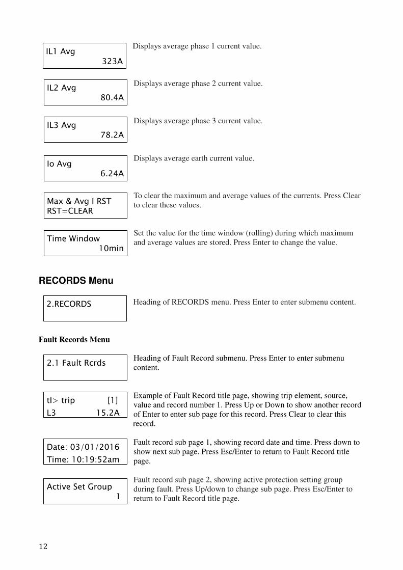
Displays average phase 1 current value.
Displays average phase 2 current value.
Displays average phase 3 current value.
Displays average earth current value.
To clear the maximum and average values of the currents. Press Clear
to clear these values.
Set the value for the time window (rolling) during which maximum
and average values are stored. Press Enter to change the value.
RECORDS Menu
Heading of RECORDS menu. Press Enter to enter submenu content.
Fault Records Menu
Heading of Fault Record submenu. Press Enter to enter submenu
content.
Example of Fault Record title page, showing trip element, source,
value and record number 1. Press Up or Down to show another record
of Enter to enter sub page for this record. Press Clear to clear this
record.
Fault record sub page 1, showing record date and time. Press down to
show next sub page. Press Esc/Enter to return to Fault Record title
page.
Fault record sub page 2, showing active protection setting group
during fault. Press Up/down to change sub page. Press Esc/Enter to
return to Fault Record title page.
IL1 Avg 323A
IL2 Avg 80.4A
IL3 Avg 78.2A
Io Avg 6.24A
Max & Avg I RST RST=CLEAR
Time Window 10min
2.RECORDS
2.1 Fault Rcrds
tI> trip [1]
L3 15.2A
Date: 03/01/2016
Time: 10:19:52am
Active Set Group 1
13
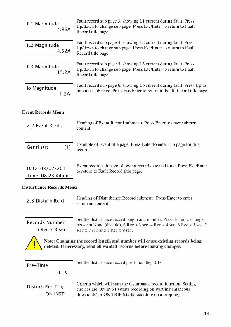
Fault record sub page 3, showing L1 current during fault. Press
Up/down to change sub page. Press Esc/Enter to return to Fault
Record title page.
Fault record sub page 4, showing L2 current during fault. Press
Up/down to change sub page. Press Esc/Enter to return to Fault
Record title page.
Fault record sub page 5, showing L3 current during fault. Press
Up/down to change sub page. Press Esc/Enter to return to Fault
Record title page.
Fault record sub page 6, showing Lo current during fault. Press Up to
previous sub page. Press Esc/Enter to return to Fault Record title page.
Event Records Menu
Heading of Event Record submenu. Press Enter to enter submenu
content.
Example of Event title page. Press Enter to enter sub page for this
record.
Event record sub page, showing record date and time. Press Esc/Enter
to return to Fault Record title page.
Disturbance Records Menu
Heading of Disturbance Record submenu. Press Enter to enter
submenu content.
Set the disturbance record length and number. Press Enter to change
between None (disable), 6 Rec x 3 sec, 4 Rec x 4 sec, 3 Rec x 5 sec, 2
Rec x 7 sec and 1 Rec x 9 sec.
Note: Changing the record length and number will cause existing records being
deleted. If necessary, read all wanted records before making changes.
Set the disturbance record pre-time. Step 0.1s.
Criteria which will start the disturbance record function. Setting
choices are ON INST (starts recording on start/instantaneous
thresholds) or ON TRIP (starts recording on a tripping).
IL1 Magnitude 4.86A
IL2 Magnitude 4.52A
IL3 Magnitude 15.2A
Io Magnitude 1.2A
2.2 Event Rcrds
Genrl strt [1]
Date: 03/02/2011
Time: 08:23:44am
2.3 Disturb Rcrd
Records Number
6 Rec x 3 sec
Pre-Time
0.1s
Disturb Rec Trig
ON INST
!!!!
14
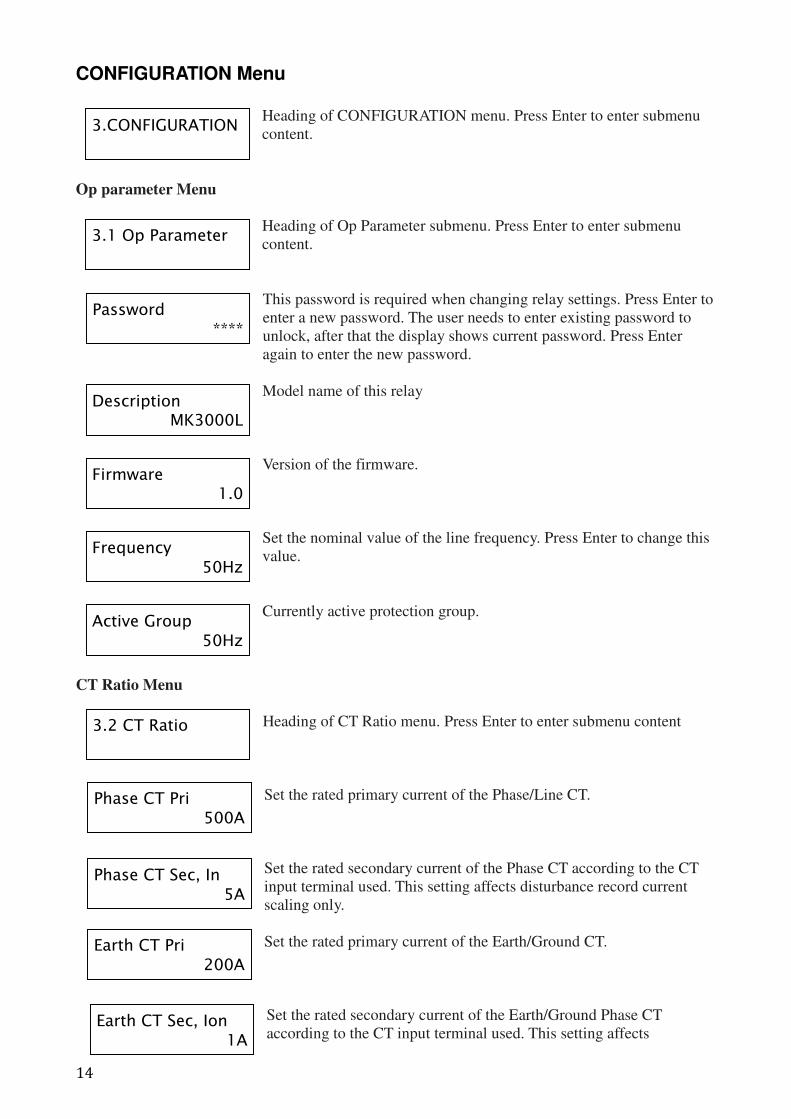
CONFIGURATION Menu
Heading of CONFIGURATION menu. Press Enter to enter submenu
content.
Op parameter Menu
Heading of Op Parameter submenu. Press Enter to enter submenu
content.
This password is required when changing relay settings. Press Enter to
enter a new password. The user needs to enter existing password to
unlock, after that the display shows current password. Press Enter
again to enter the new password.
Model name of this relay
Version of the firmware.
Set the nominal value of the line frequency. Press Enter to change this
value.
Currently active protection group.
CT Ratio Menu
Heading of CT Ratio menu. Press Enter to enter submenu content
Set the rated primary current of the Phase/Line CT.
Set the rated secondary current of the Phase CT according to the CT
input terminal used. This setting affects disturbance record current
scaling only.
Set the rated primary current of the Earth/Ground CT.
Set the rated secondary current of the Earth/Ground Phase CT
according to the CT input terminal used. This setting affects
3.CONFIGURATION
3.1 Op Parameter
Password ****
Description MK3000L
Firmware 1.0
Frequency 50Hz
3.2 CT Ratio
Phase CT Pri 500A
Earth CT Pri 200A
Active Group 50Hz
Phase CT Sec, In 5A
Earth CT Sec, Ion 1A
15
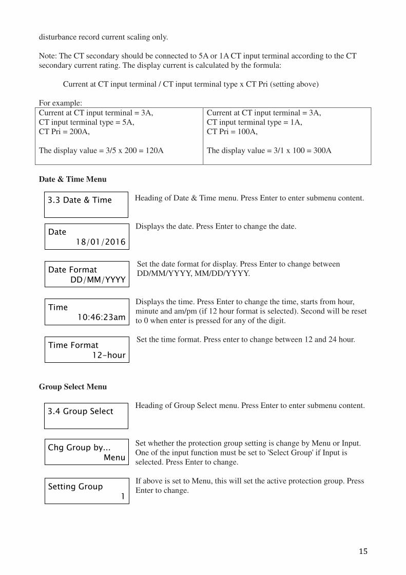
disturbance record current scaling only.
Note: The CT secondary should be connected to 5A or 1A CT input terminal according to the CT
secondary current rating. The display current is calculated by the formula:
Current at CT input terminal / CT input terminal type x CT Pri (setting above)
For example:
Current at CT input terminal = 3A,
CT input terminal type = 5A,
CT Pri = 200A,
The display value = 3/5 x 200 = 120A
Current at CT input terminal = 3A,
CT input terminal type = 1A,
CT Pri = 100A,
The display value = 3/1 x 100 = 300A
Date & Time Menu
Heading of Date & Time menu. Press Enter to enter submenu content.
Displays the date. Press Enter to change the date.
Set the date format for display. Press Enter to change between
DD/MM/YYYY, MM/DD/YYYY.
Displays the time. Press Enter to change the time, starts from hour,
minute and am/pm (if 12 hour format is selected). Second will be reset
to 0 when enter is pressed for any of the digit.
Set the time format. Press enter to change between 12 and 24 hour.
Group Select Menu
Heading of Group Select menu. Press Enter to enter submenu content.
Set whether the protection group setting is change by Menu or Input.
One of the input function must be set to 'Select Group' if Input is
selected. Press Enter to change.
If above is set to Menu, this will set the active protection group. Press
Enter to change.
3.3 Date & Time
Date 18/01/2016
Date Format DD/MM/YYYY
Time 10:46:23am
Time Format 12-hour
3.4 Group Select
Chg Group by... Menu
Setting Group 1
16
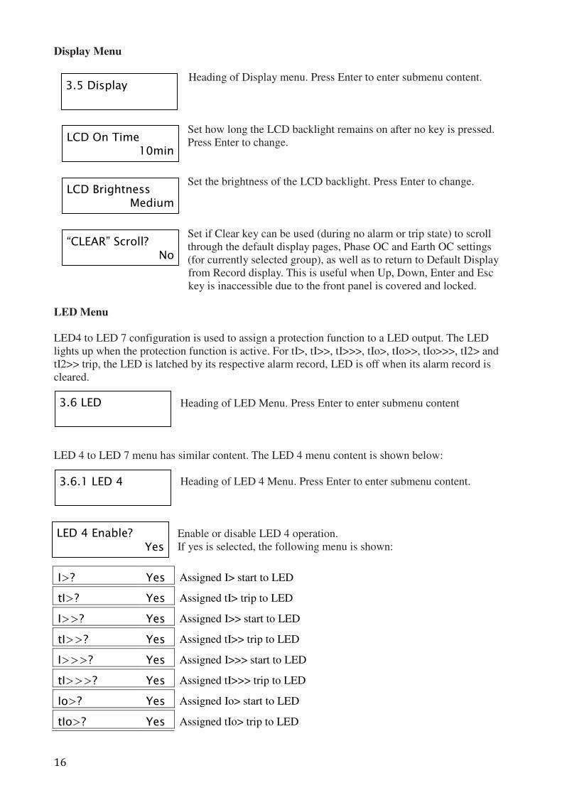
Display Menu
Heading of Display menu. Press Enter to enter submenu content.
Set how long the LCD backlight remains on after no key is pressed.
Press Enter to change.
Set the brightness of the LCD backlight. Press Enter to change.
Set if Clear key can be used (during no alarm or trip state) to scroll
through the default display pages, Phase OC and Earth OC settings
(for currently selected group), as well as to return to Default Display
from Record display. This is useful when Up, Down, Enter and Esc
key is inaccessible due to the front panel is covered and locked.
LED Menu
LED4 to LED 7 configuration is used to assign a protection function to a LED output. The LED
lights up when the protection function is active. For tI>, tI>>, tI>>>, tIo>, tIo>>, tIo>>>, tI2> and
tI2>> trip, the LED is latched by its respective alarm record, LED is off when its alarm record is
cleared.
Heading of LED Menu. Press Enter to enter submenu content
LED 4 to LED 7 menu has similar content. The LED 4 menu content is shown below:
Heading of LED 4 Menu. Press Enter to enter submenu content.
Enable or disable LED 4 operation.
If yes is selected, the following menu is shown:
I>? Yes Assigned I> start to LED
tI>? Yes Assigned tI> trip to LED
I>>? Yes Assigned I>> start to LED
tI>>? Yes Assigned tI>> trip to LED
I>>>? Yes Assigned I>>> start to LED
tI>>>? Yes Assigned tI>>> trip to LED
Io>? Yes Assigned Io> start to LED
tIo>? Yes Assigned tIo> trip to LED
3.5 Display
LCD On Time 10min
LCD Brightness Medium
“CLEAR” Scroll? No
3.6 LED
3.6.1 LED 4
LED 4 Enable? Yes
17
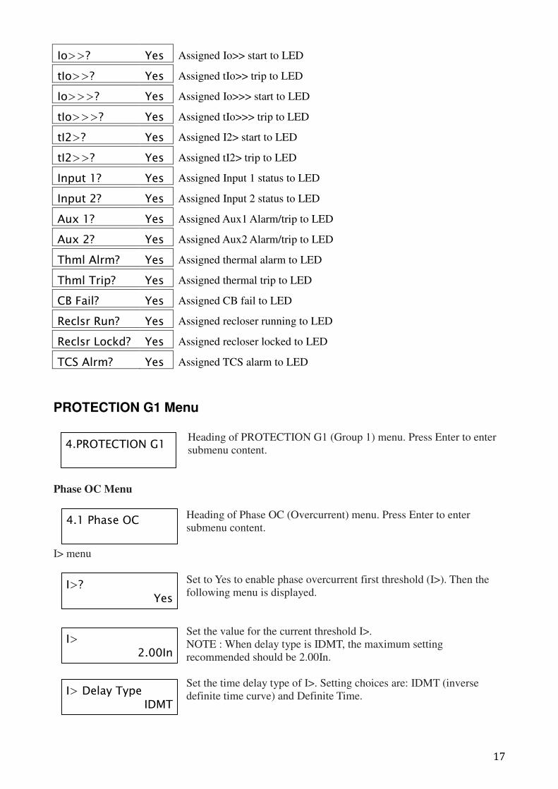
Io>>? Yes Assigned Io>> start to LED
tIo>>? Yes Assigned tIo>> trip to LED
Io>>>? Yes Assigned Io>>> start to LED
tIo>>>? Yes Assigned tIo>>> trip to LED
tI2>? Yes Assigned I2> start to LED
tI2>>? Yes Assigned tI2> trip to LED
Input 1? Yes Assigned Input 1 status to LED
Input 2? Yes Assigned Input 2 status to LED
Aux 1? Yes Assigned Aux1 Alarm/trip to LED
Aux 2? Yes Assigned Aux2 Alarm/trip to LED
Thml Alrm? Yes Assigned thermal alarm to LED
Thml Trip? Yes Assigned thermal trip to LED
CB Fail? Yes Assigned CB fail to LED
Reclsr Run? Yes Assigned recloser running to LED
Reclsr Lockd? Yes Assigned recloser locked to LED
TCS Alrm? Yes Assigned TCS alarm to LED
PROTECTION G1 Menu
Heading of PROTECTION G1 (Group 1) menu. Press Enter to enter
submenu content.
Phase OC Menu
Heading of Phase OC (Overcurrent) menu. Press Enter to enter
submenu content.
I> menu
Set to Yes to enable phase overcurrent first threshold (I>). Then the
following menu is displayed.
Set the value for the current threshold I>.
NOTE : When delay type is IDMT, the maximum setting
recommended should be 2.00In.
Set the time delay type of I>. Setting choices are: IDMT (inverse
definite time curve) and Definite Time.
4.PROTECTION G1
4.1 Phase OC
I>? Yes
I> 2.00In
I> Delay Type IDMT
18
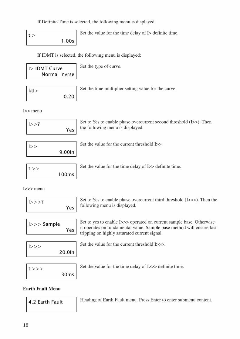
If Definite Time is selected, the following menu is displayed:
Set the value for the time delay of I> definite time.
If IDMT is selected, the following menu is displayed:
Set the type of curve.
Set the time multiplier setting value for the curve.
I>> menu
Set to Yes to enable phase overcurrent second threshold (I>>). Then
the following menu is displayed.
Set the value for the current threshold I>>.
Set the value for the time delay of I>> definite time.
I>>> menu
Set to Yes to enable phase overcurrent third threshold (I>>>). Then the
following menu is displayed.
Set to yes to enable I>>> operated on current sample base. Otherwise
it operates on fundamental value. Sample base method will ensure fast
tripping on highly saturated current signal.
Set the value for the current threshold I>>>.
Set the value for the time delay of I>>> definite time.
Earth Fault Menu
Heading of Earth Fault menu. Press Enter to enter submenu content.
tI> 1.00s
I> IDMT Curve Normal Invrse
ktI> 0.20
I>>? Yes
I>> 9.00In
tI>> 100ms
I>>>? Yes
I>>> Sample Yes
I>>> 20.0In
tI>>> 30ms
4.2 Earth Fault
19
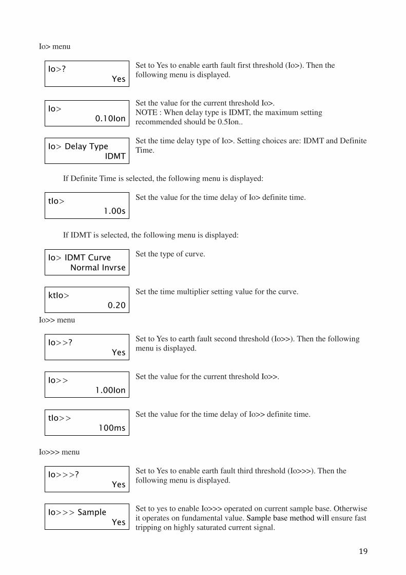
Io> menu
Set to Yes to enable earth fault first threshold (Io>). Then the
following menu is displayed.
Set the value for the current threshold Io>.
NOTE : When delay type is IDMT, the maximum setting
recommended should be 0.5Ion..
Set the time delay type of Io>. Setting choices are: IDMT and Definite
Time.
If Definite Time is selected, the following menu is displayed:
Set the value for the time delay of Io> definite time.
If IDMT is selected, the following menu is displayed:
Set the type of curve.
Set the time multiplier setting value for the curve.
Io>> menu
Set to Yes to earth fault second threshold (Io>>). Then the following
menu is displayed.
Set the value for the current threshold Io>>.
Set the value for the time delay of Io>> definite time.
Io>>> menu
Set to Yes to enable earth fault third threshold (Io>>>). Then the
following menu is displayed.
Set to yes to enable Io>>> operated on current sample base. Otherwise
it operates on fundamental value. Sample base method will ensure fast
tripping on highly saturated current signal.
Io>? Yes
Io> 0.10Ion
Io> Delay Type IDMT
tIo> 1.00s
Io> IDMT Curve Normal Invrse
ktIo> 0.20
Io>>? Yes
Io>> 1.00Ion
tIo>> 100ms
Io>>>? Yes
Io>>> Sample Yes
20
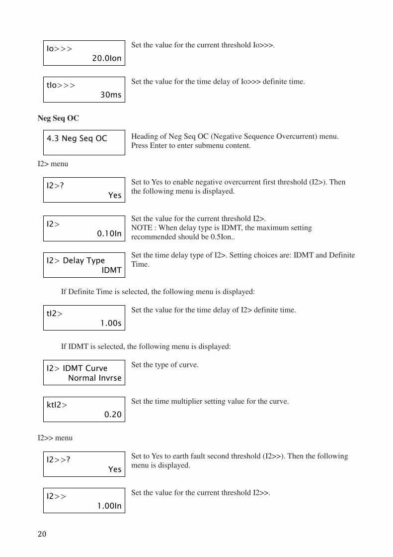
Set the value for the current threshold Io>>>.
Set the value for the time delay of Io>>> definite time.
Neg Seq OC
Heading of Neg Seq OC (Negative Sequence Overcurrent) menu.
Press Enter to enter submenu content.
I2> menu
Set to Yes to enable negative overcurrent first threshold (I2>). Then
the following menu is displayed.
Set the value for the current threshold I2>.
NOTE : When delay type is IDMT, the maximum setting
recommended should be 0.5Ion..
Set the time delay type of I2>. Setting choices are: IDMT and Definite
Time.
If Definite Time is selected, the following menu is displayed:
Set the value for the time delay of I2> definite time.
If IDMT is selected, the following menu is displayed:
Set the type of curve.
Set the time multiplier setting value for the curve.
I2>> menu
Set to Yes to earth fault second threshold (I2>>). Then the following
menu is displayed.
Set the value for the current threshold I2>>.
Io>>> 20.0Ion
tIo>>> 30ms
4.3 Neg Seq OC
I2>? Yes
I2> 0.10In
I2> Delay Type IDMT
tI2> 1.00s
I2> IDMT Curve Normal Invrse
ktI2> 0.20
I2>>? Yes
I2>> 1.00In
21
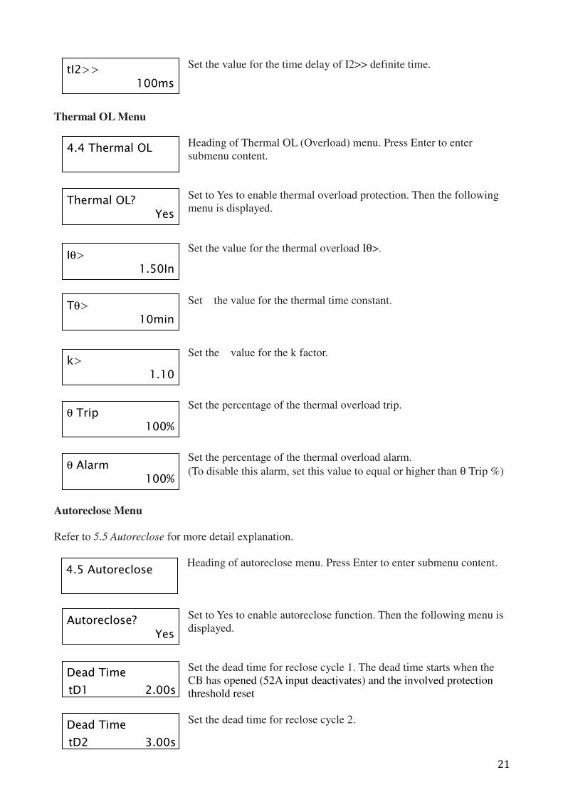
Set the value for the time delay of I2>> definite time.
Thermal OL Menu
Heading of Thermal OL (Overload) menu. Press Enter to enter
submenu content.
Set to Yes to enable thermal overload protection. Then the following
menu is displayed.
Set the value for the thermal overload Iθ>.
Set the value for the thermal time constant.
Set the value for the k factor.
Set the percentage of the thermal overload trip.
Set the percentage of the thermal overload alarm.
(To disable this alarm, set this value to equal or higher than θ Trip %)
Autoreclose Menu
Refer to 5.5 Autoreclose for more detail explanation.
Heading of autoreclose menu. Press Enter to enter submenu content.
Set to Yes to enable autoreclose function. Then the following menu is
displayed.
Set the dead time for reclose cycle 1. The dead time starts when the
CB has opened (52A input deactivates) and the involved protection
threshold reset
Set the dead time for reclose cycle 2.
4.4 Thermal OL
Thermal OL? Yes
Iθ> 1.50In
Tθ> 10min
k> 1.10
θ Trip 100%
θ Alarm 100%
tI2>> 100ms
4.5 Autoreclose
Autoreclose? Yes
Dead Time
tD1 2.00s
Dead Time
tD2 3.00s
22
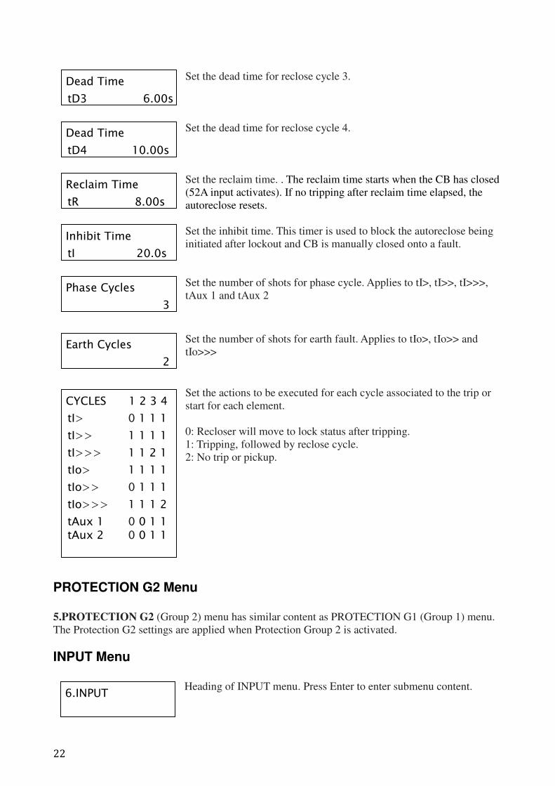
Set the dead time for reclose cycle 3.
Set the dead time for reclose cycle 4.
Set the reclaim time. . The reclaim time starts when the CB has closed
(52A input activates). If no tripping after reclaim time elapsed, the
autoreclose resets.
Set the inhibit time. This timer is used to block the autoreclose being
initiated after lockout and CB is manually closed onto a fault.
Set the number of shots for phase cycle. Applies to tI>, tI>>, tI>>>,
tAux 1 and tAux 2
Set the number of shots for earth fault. Applies to tIo>, tIo>> and
tIo>>>
Set the actions to be executed for each cycle associated to the trip or
start for each element.
0: Recloser will move to lock status after tripping.
1: Tripping, followed by reclose cycle.
2: No trip or pickup.
PROTECTION G2 Menu
5.PROTECTION G2 (Group 2) menu has similar content as PROTECTION G1 (Group 1) menu.
The Protection G2 settings are applied when Protection Group 2 is activated.
INPUT Menu
Heading of INPUT menu. Press Enter to enter submenu content.
6.INPUT
Dead Time
tD3 6.00s
Dead Time
tD4 10.00s
Reclaim Time
tR 8.00s
Inhibit Time
tI 20.0s
Phase Cycles
3
Earth Cycles
2
CYCLES 1 2 3 4
tI> 0 1 1 1
tI>> 1 1 1 1
tI>>> 1 1 2 1
tIo> 1 1 1 1
tIo>> 0 1 1 1
tIo>>> 1 1 1 2
tAux 1 0 0 1 1 tAux 2 0 0 1 1
23
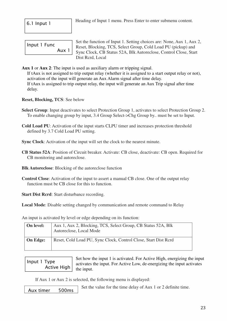
Heading of Input 1 menu. Press Enter to enter submenu content.
Set the function of Input 1. Setting choices are: None, Aux 1, Aux 2,
Reset, Blocking, TCS, Select Group, Cold Load PU (pickup) and
Sync Clock, CB Status 52A, Blk Autoreclose, Control Close, Start
Dist Rcrd, Local
Aux 1 or Aux 2: The input is used as auxiliary alarm or tripping signal.
If tAux is not assigned to trip output relay (whether it is assigned to a start output relay or not),
activation of the input will generate an Aux Alarm signal after time delay.
If tAux is assigned to trip output relay, the input will generate an Aux Trip signal after time
delay.
Reset, Blocking, TCS: See below
Select Group: Input deactivates to select Protection Group 1, activates to select Protection Group 2.
To enable changing group by input, 3.4 Group Select->Chg Group by.. must be set to Input.
Cold Load PU: Activation of the input starts CLPU timer and increases protection threshold
defined by 3.7 Cold Load PU setting.
Sync Clock: Activation of the input will set the clock to the nearest minute.
CB Status 52A: Position of Circuit breaker. Activate: CB close, deactivate: CB open. Required for
CB monitoring and autoreclose.
Blk Autoreclose: Blocking of the autoreclose function
Control Close: Activation of the input to assert a manual CB close. One of the output relay
function must be CB close for this to function.
Start Dist Rcrd: Start disturbance recording.
Local Mode: Disable setting changed by communication and remote command to Relay
An input is activated by level or edge depending on its function:
On level: Aux 1, Aux 2, Blocking, TCS, Select Group, CB Status 52A, Blk
Autoreclose, Local Mode
On Edge:
Reset, Cold Load PU, Sync Clock, Control Close, Start Dist Rcrd
Set how the input 1 is activated. For Active High, energizing the input
activates the input. For Active Low, de-energizing the input activates
the input.
If Aux 1 or Aux 2 is selected, the following menu is displayed:
Set the value for the time delay of Aux 1 or 2 definite time.
Aux timer 500ms
6.1 Input 1
Input 1 Func Aux 1
Input 1 Type Active High
24
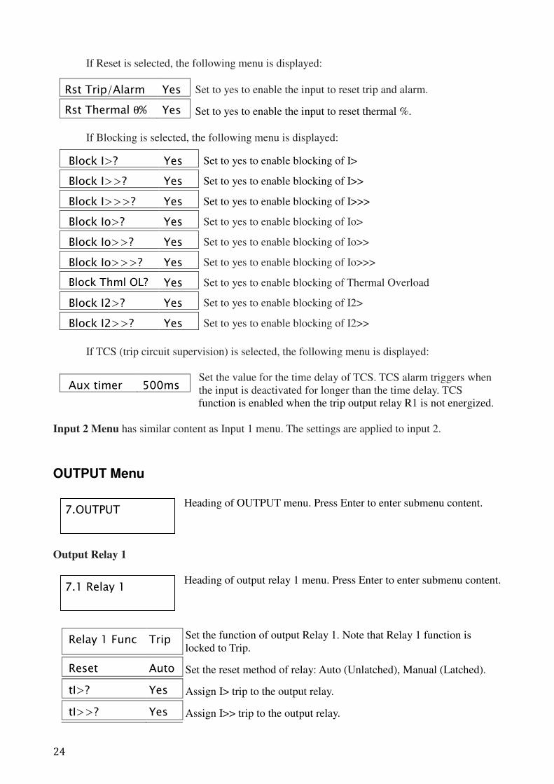
If Reset is selected, the following menu is displayed:
If Blocking is selected, the following menu is displayed:
Block I>? Yes Set to yes to enable blocking of I>
Block I>>? Yes Set to yes to enable blocking of I>>
Block I>>>? Yes Set to yes to enable blocking of I>>>
Block Io>? Yes Set to yes to enable blocking of Io>
Block Io>>? Yes Set to yes to enable blocking of Io>>
Block Io>>>? Yes Set to yes to enable blocking of Io>>>
Block Thml OL? Yes Set to yes to enable blocking of Thermal Overload
Block I2>? Yes Set to yes to enable blocking of I2>
Block I2>>? Yes Set to yes to enable blocking of I2>>
If TCS (trip circuit supervision) is selected, the following menu is displayed:
Set the value for the time delay of TCS. TCS alarm triggers when
the input is deactivated for longer than the time delay. TCS
function is enabled when the trip output relay R1 is not energized.
Input 2 Menu has similar content as Input 1 menu. The settings are applied to input 2.
OUTPUT Menu
Heading of OUTPUT menu. Press Enter to enter submenu content.
Output Relay 1
Heading of output relay 1 menu. Press Enter to enter submenu content.
Rst Trip/Alarm Yes Set to yes to enable the input to reset trip and alarm.
Rst Thermal θ% Yes Set to yes to enable the input to reset thermal %.
Aux timer 500ms
Relay 1 Func Trip Set the function of output Relay 1. Note that Relay 1 function is
locked to Trip.
Reset Auto Set the reset method of relay: Auto (Unlatched), Manual (Latched).
tI>? Yes Assign I> trip to the output relay.
tI>>? Yes Assign I>> trip to the output relay.
7.OUTPUT
7.1 Relay 1
25
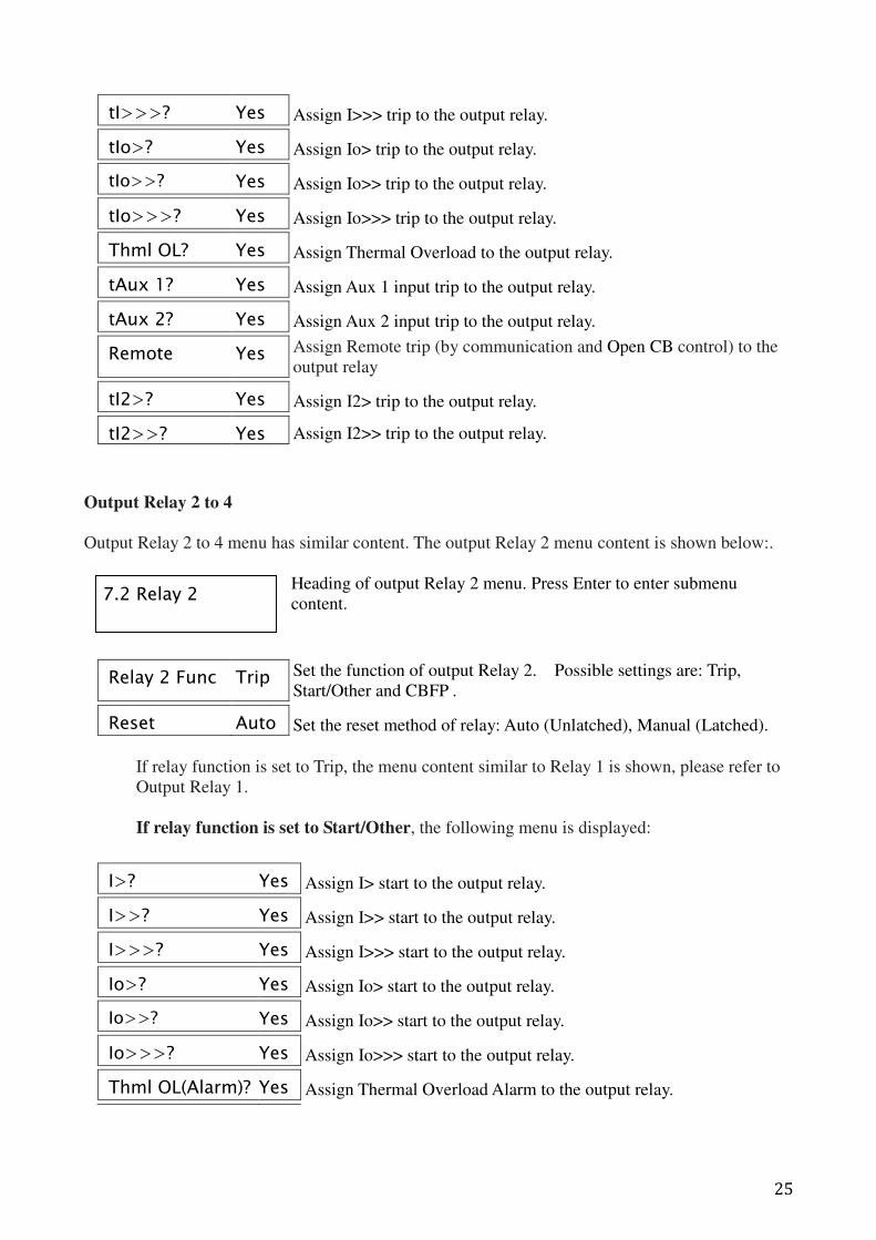
Output Relay 2 to 4
Output Relay 2 to 4 menu has similar content. The output Relay 2 menu content is shown below:.
Heading of output Relay 2 menu. Press Enter to enter submenu
content.
If relay function is set to Trip, the menu content similar to Relay 1 is shown, please refer to
Output Relay 1.
If relay function is set to Start/Other, the following menu is displayed:
tI>>>? Yes Assign I>>> trip to the output relay.
tIo>? Yes Assign Io> trip to the output relay.
tIo>>? Yes Assign Io>> trip to the output relay.
tIo>>>? Yes Assign Io>>> trip to the output relay.
Thml OL? Yes Assign Thermal Overload to the output relay.
tAux 1? Yes Assign Aux 1 input trip to the output relay.
tAux 2? Yes Assign Aux 2 input trip to the output relay.
Remote Yes Assign Remote trip (by communication and Open CB control) to the
output relay
tI2>? Yes Assign I2> trip to the output relay.
tI2>>? Yes Assign I2>> trip to the output relay.
Relay 2 Func Trip Set the function of output Relay 2. Possible settings are: Trip,
Start/Other and CBFP .
Reset Auto Set the reset method of relay: Auto (Unlatched), Manual (Latched).
I>? Yes Assign I> start to the output relay.
I>>? Yes Assign I>> start to the output relay.
I>>>? Yes Assign I>>> start to the output relay.
Io>? Yes Assign Io> start to the output relay.
Io>>? Yes Assign Io>> start to the output relay.
Io>>>? Yes Assign Io>>> start to the output relay.
Thml OL(Alarm)? Yes Assign Thermal Overload Alarm to the output relay.
7.2 Relay 2
26
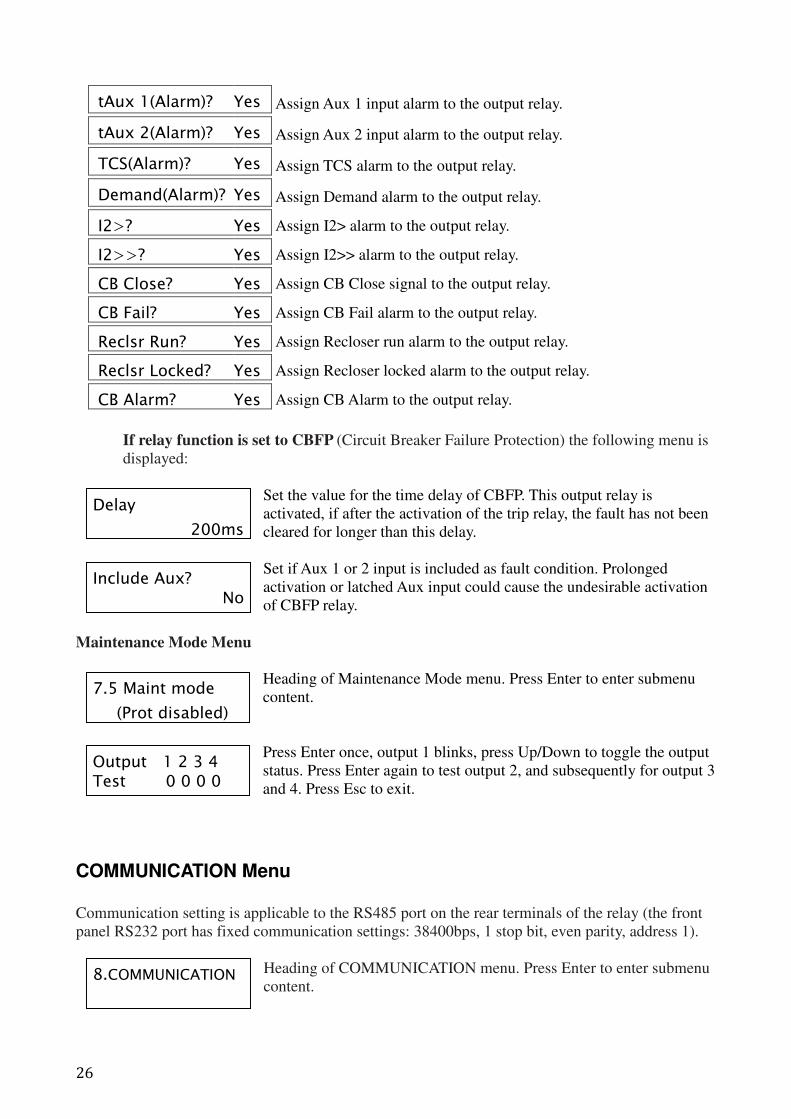
If relay function is set to CBFP (Circuit Breaker Failure Protection) the following menu is
displayed:
Set the value for the time delay of CBFP. This output relay is
activated, if after the activation of the trip relay, the fault has not been
cleared for longer than this delay.
Set if Aux 1 or 2 input is included as fault condition. Prolonged
activation or latched Aux input could cause the undesirable activation
of CBFP relay.
Maintenance Mode Menu
Heading of Maintenance Mode menu. Press Enter to enter submenu
content.
Press Enter once, output 1 blinks, press Up/Down to toggle the output
status. Press Enter again to test output 2, and subsequently for output 3
and 4. Press Esc to exit.
COMMUNICATION Menu
Communication setting is applicable to the RS485 port on the rear terminals of the relay (the front
panel RS232 port has fixed communication settings: 38400bps, 1 stop bit, even parity, address 1).
Heading of COMMUNICATION menu. Press Enter to enter submenu
content.
tAux 1(Alarm)? Yes Assign Aux 1 input alarm to the output relay.
tAux 2(Alarm)? Yes Assign Aux 2 input alarm to the output relay.
TCS(Alarm)? Yes Assign TCS alarm to the output relay.
Demand(Alarm)? Yes Assign Demand alarm to the output relay.
I2>? Yes Assign I2> alarm to the output relay.
I2>>? Yes Assign I2>> alarm to the output relay.
CB Close? Yes Assign CB Close signal to the output relay.
CB Fail? Yes Assign CB Fail alarm to the output relay.
Reclsr Run? Yes Assign Recloser run alarm to the output relay.
Reclsr Locked? Yes Assign Recloser locked alarm to the output relay.
CB Alarm? Yes Assign CB Alarm to the output relay.
Delay
200ms
Include Aux? No
8.COMMUNICATION
7.5 Maint mode
(Prot disabled)
Output 1 2 3 4 Test 0 0 0 0
27
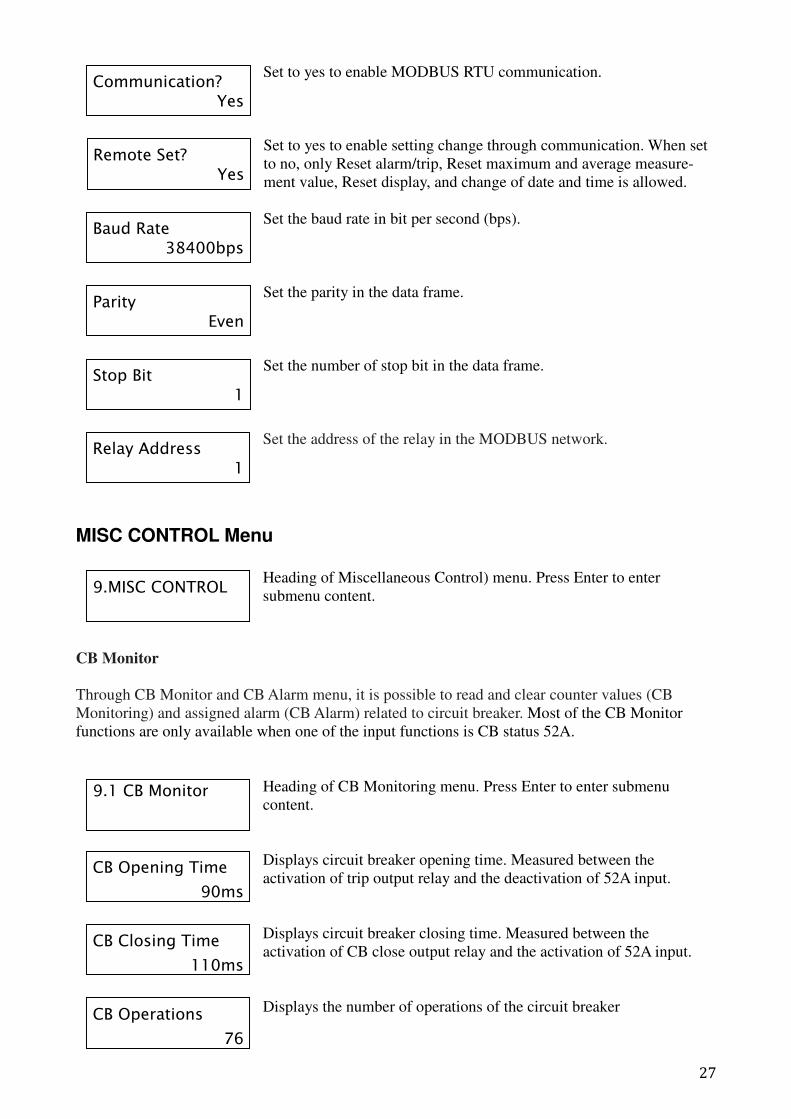
Set to yes to enable MODBUS RTU communication.
Set to yes to enable setting change through communication. When set
to no, only Reset alarm/trip, Reset maximum and average measure-
ment value, Reset display, and change of date and time is allowed.
Set the baud rate in bit per second (bps).
Set the parity in the data frame.
Set the number of stop bit in the data frame.
Set the address of the relay in the MODBUS network.
MISC CONTROL Menu
Heading of Miscellaneous Control) menu. Press Enter to enter
submenu content.
CB Monitor
Through CB Monitor and CB Alarm menu, it is possible to read and clear counter values (CB
Monitoring) and assigned alarm (CB Alarm) related to circuit breaker. Most of the CB Monitor
functions are only available when one of the input functions is CB status 52A.
Heading of CB Monitoring menu. Press Enter to enter submenu
content.
Displays circuit breaker opening time. Measured between the
activation of trip output relay and the deactivation of 52A input.
Displays circuit breaker closing time. Measured between the
activation of CB close output relay and the activation of 52A input.
Displays the number of operations of the circuit breaker
Baud Rate 38400bps
Parity Even
Stop Bit 1
Relay Address 1
Communication? Yes
Remote Set? Yes
9.1 CB Monitor
CB Opening Time
90ms
CB Closing Time
110ms
CB Operations
76
9.MISC CONTROL
28
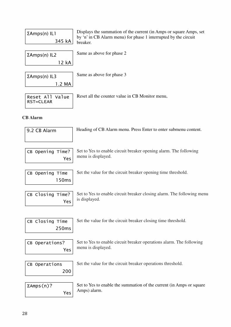
Displays the summation of the current (in Amps or square Amps, set
by ‘n’ in CB Alarm menu) for phase 1 interrupted by the circuit
breaker.
Same as above for phase 2
Same as above for phase 3
Reset all the counter value in CB Monitor menu,
CB Alarm
Heading of CB Alarm menu. Press Enter to enter submenu content.
Set to Yes to enable circuit breaker opening alarm. The following
menu is displayed.
Set the value for the circuit breaker opening time threshold.
Set to Yes to enable circuit breaker closing alarm. The following menu
is displayed.
Set the value for the circuit breaker closing time threshold.
Set to Yes to enable circuit breaker operations alarm. The following
menu is displayed.
Set the value for the circuit breaker operations threshold.
Set to Yes to enable the summation of the current (in Amps or square
Amps) alarm.
9.2 CB Alarm
ΣAmps(n) IL1
345 kA
ΣAmps(n) IL2
12 kA
ΣAmps(n) IL3
1.2 MA
Reset All Value RST=CLEAR
CB Opening Time?
Yes
CB Opening Time
150ms
CB Closing Time?
Yes
CB Closing Time
250ms
CB Operations?
Yes
CB Operations
200
ΣAmps(n)?
Yes
29
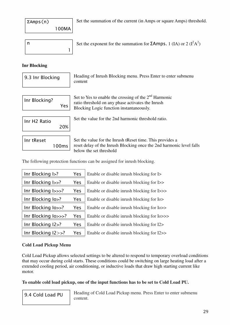
Set the summation of the current (in Amps or square Amps) threshold.
Set the exponent for the summation for ΣAmps. 1 (IA) or 2 (I2A
2)
Inr Blocking
Heading of Inrush Blocking menu. Press Enter to enter submenu
content
Set to Yes to enable the crossing of the 2nd
Harmonic
ratio threshold on any phase activates the Inrush
Blocking Logic function instantaneously.
Set the value for the 2nd harmonic threshold ratio.
Set the value for the Inrush tReset time. This provides a
reset delay of the Inrush Blocking once the 2nd harmonic level falls
below the set threshold
The following protection functions can be assigned for inrush blocking.
Inr Blocking I>? Yes Enable or disable inrush blocking for I>
Inr Blocking I>>? Yes Enable or disable inrush blocking for I>>
Inr Blocking I>>>? Yes Enable or disable inrush blocking for I>>>
Inr Blocking Io>? Yes Enable or disable inrush blocking for Io>
Inr Blocking Io>>? Yes Enable or disable inrush blocking for Io>>
Inr Blocking Io>>>? Yes Enable or disable inrush blocking for Io>>>
Inr Blocking I2>? Yes Enable or disable inrush blocking for I2>
Inr Blocking I2>>? Yes Enable or disable inrush blocking for I2>>
Cold Load Pickup Menu
Cold Load Pickup allows selected settings to be altered to respond to temporary overload conditions
that may occur during cold starts. These conditions could be switching on large heating load after a
extended cooling period, air conditioning, or inductive loads that draw high starting current like
motor.
To enable cold load pickup, one of the input functions has to be set to Cold Load PU.
Heading of Cold Load Pickup menu. Press Enter to enter submenu
content.
ΣAmps(n)
100MA
n
1
9.4 Cold Load PU
9.3 Inr Blocking
Inr Blocking? Yes
Inr H2 Ratio 20%
Inr tReset 100ms
30
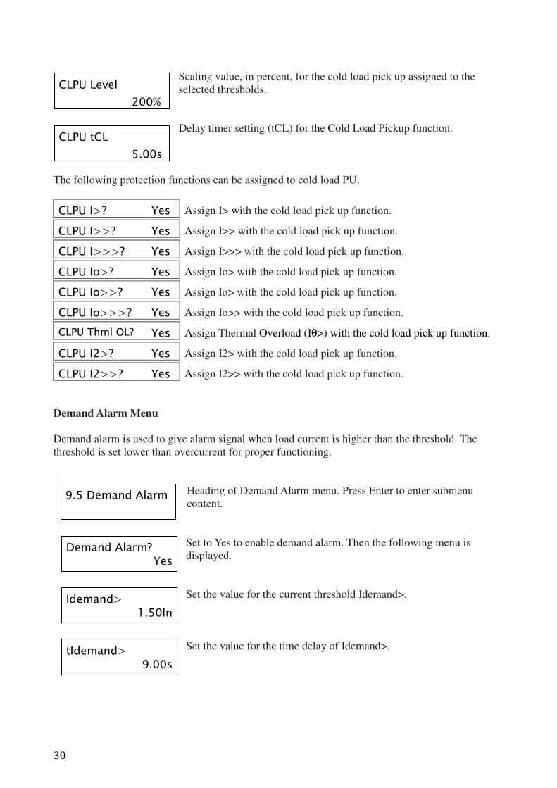
Scaling value, in percent, for the cold load pick up assigned to the
selected thresholds.
Delay timer setting (tCL) for the Cold Load Pickup function.
The following protection functions can be assigned to cold load PU.
CLPU I>? Yes Assign I> with the cold load pick up function.
CLPU I>>? Yes Assign I>> with the cold load pick up function.
CLPU I>>>? Yes Assign I>>> with the cold load pick up function.
CLPU Io>? Yes Assign Io> with the cold load pick up function.
CLPU Io>>? Yes Assign Io> with the cold load pick up function.
CLPU Io>>>? Yes Assign Io>> with the cold load pick up function.
CLPU Thml OL? Yes Assign Thermal Overload (Iθ>) with the cold load pick up function.
CLPU I2>? Yes Assign I2> with the cold load pick up function.
CLPU I2>>? Yes Assign I2>> with the cold load pick up function.
Demand Alarm Menu
Demand alarm is used to give alarm signal when load current is higher than the threshold. The
threshold is set lower than overcurrent for proper functioning.
Heading of Demand Alarm menu. Press Enter to enter submenu
content.
Set to Yes to enable demand alarm. Then the following menu is
displayed.
Set the value for the current threshold Idemand>.
Set the value for the time delay of Idemand>.
CLPU Level
200%
CLPU tCL
5.00s
9.5 Demand Alarm
Demand Alarm? Yes
Idemand> 1.50In
tIdemand> 9.00s
31
5.0 Functions and Descriptions
5.1 Circuit Breaker Failure Protection
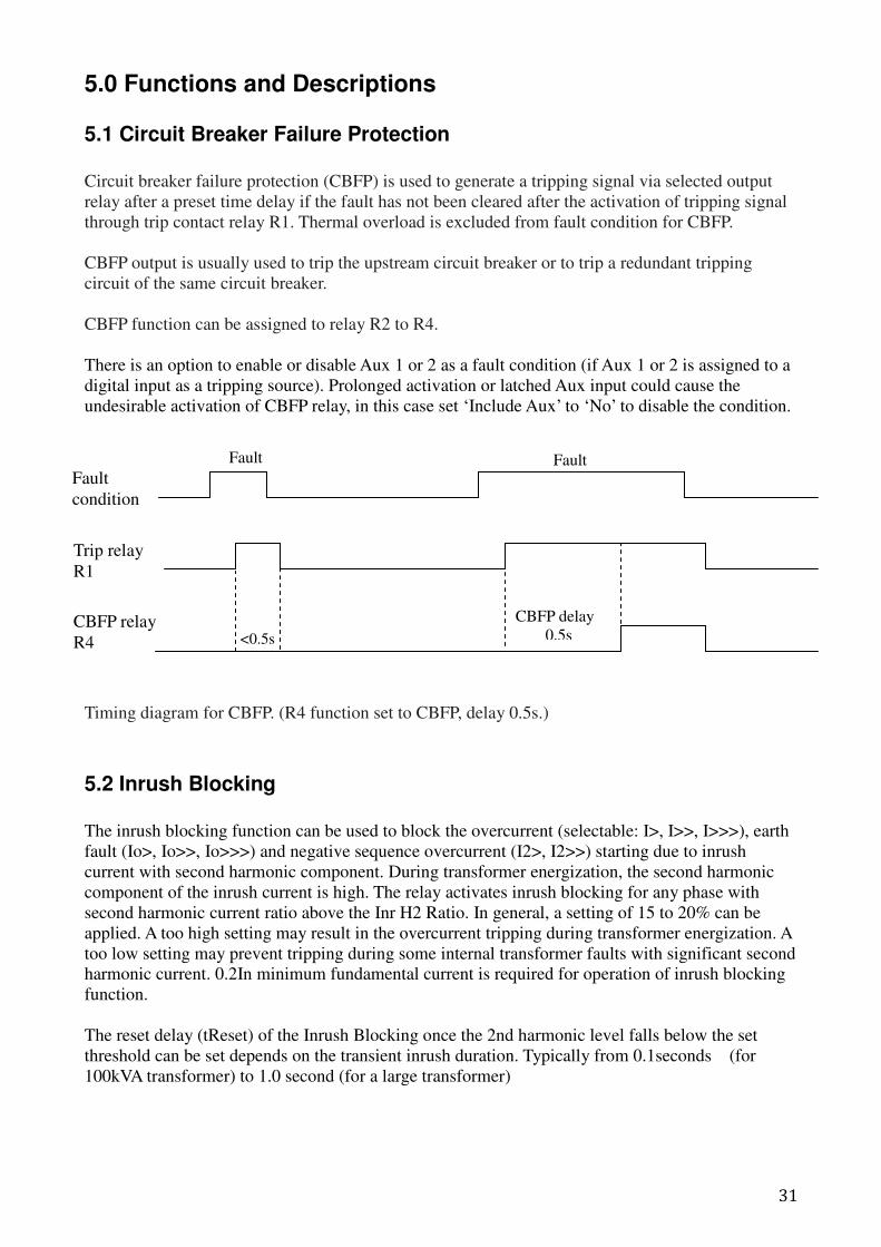
Circuit breaker failure protection (CBFP) is used to generate a tripping signal via selected output
relay after a preset time delay if the fault has not been cleared after the activation of tripping signal
through trip contact relay R1. Thermal overload is excluded from fault condition for CBFP.
CBFP output is usually used to trip the upstream circuit breaker or to trip a redundant tripping
circuit of the same circuit breaker.
CBFP function can be assigned to relay R2 to R4.
There is an option to enable or disable Aux 1 or 2 as a fault condition (if Aux 1 or 2 is assigned to a
digital input as a tripping source). Prolonged activation or latched Aux input could cause the
undesirable activation of CBFP relay, in this case set ‘Include Aux’ to ‘No’ to disable the condition.
Timing diagram for CBFP. (R4 function set to CBFP, delay 0.5s.)
5.2 Inrush Blocking
The inrush blocking function can be used to block the overcurrent (selectable: I>, I>>, I>>>), earth
fault (Io>, Io>>, Io>>>) and negative sequence overcurrent (I2>, I2>>) starting due to inrush
current with second harmonic component. During transformer energization, the second harmonic
component of the inrush current is high. The relay activates inrush blocking for any phase with
second harmonic current ratio above the Inr H2 Ratio. In general, a setting of 15 to 20% can be
applied. A too high setting may result in the overcurrent tripping during transformer energization. A
too low setting may prevent tripping during some internal transformer faults with significant second
harmonic current. 0.2In minimum fundamental current is required for operation of inrush blocking
function.
The reset delay (tReset) of the Inrush Blocking once the 2nd harmonic level falls below the set
threshold can be set depends on the transient inrush duration. Typically from 0.1seconds (for
100kVA transformer) to 1.0 second (for a large transformer)
Trip relay
R1
Fault
condition
CBFP relay
R4
CBFP delay
0.5s
Fault Fault
<0.5s
32
Ieq
k.Iθ>
5.3 Thermal Overload Protection
Thermal overload protection can be used to prevent damages to the equipment of the electrical plant.
A prolonged overloading causes excessive heating, which may result in deterioration of the
insulation, or in extreme cases, insulation failure.
Load current is used to calculate the heating and cooling effect of the equipment to be protected.
The highest phase current is automatically used as input information for the thermal model.
The thermal overload protection can be set with both alarm and trip stages, θ Trip % and θ Alarm
%, with 5% below the set % for resetting.
The heating within any plant equipment, such as cables or transformers, is of resistive type (I²R x t).
Thus the thermal time characteristic used in the relay is based on current squared, integrated over
time.
Protection equipment is designed to operate continuously at a temperature corresponding to its full
load rating, where heat generated is balanced with heat dissipated. Over-temperature conditions
occur when currents in excess of rating flow for a certain period of time. It can be shown that
temperatures during heating follow exponential time constants and a similar exponential decrease of
temperature occurs during cooling.
In order to apply this protection element, the thermal time constant (Tθ) of the plant equipment to
be protected is therefore required.
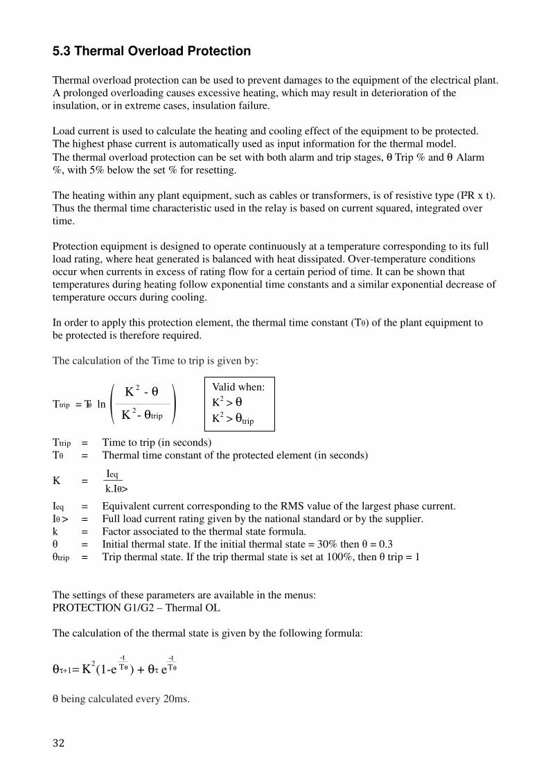
The calculation of the Time to trip is given by:
Ttrip = Time to trip (in seconds)
Tθ = Thermal time constant of the protected element (in seconds)
K =
Ieq = Equivalent current corresponding to the RMS value of the largest phase current.
Iθ > = Full load current rating given by the national standard or by the supplier.
k = Factor associated to the thermal state formula.
θ = Initial thermal state. If the initial thermal state = 30% then θ = 0.3
θtrip = Trip thermal state. If the trip thermal state is set at 100%, then θ trip = 1
The settings of these parameters are available in the menus:
PROTECTION G1/G2 – Thermal OL
The calculation of the thermal state is given by the following formula:
θ being calculated every 20ms.
θτ+1= K 2 (1-e ) +
-t
Tθ θτ e-t
Tθ
Ttrip = Tθ ln-
- θ
θtripK
K
2
2
( )Valid when:
K2 > θ
K2 > θtrip
33
5.4 Trip Circuit Supervision
Trip Circuit Supervision (TCS) enables the trip circuit to be monitor. To enable TCS function, set
one of the Digital Input function to TCS (at the INPUT Menu), Input Type as Active High and set
the appropriate TCS delay time.
The continuity of trip circuit is monitor when Trip contact R1 is not energized. When the input
detects no signal for a time longer than the TCS delay time, TCS alarm pops up to warn the failure
of trip circuit. Three examples of application are given below.
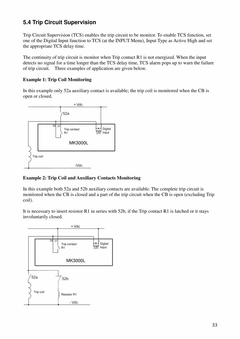
Example 1: Trip Coil Monitoring
In this example only 52a auxiliary contact is available; the trip coil is monitored when the CB is
open or closed.
Example 2: Trip Coil and Auxiliary Contacts Monitoring
In this example both 52a and 52b auxiliary contacts are available. The complete trip circuit is
monitored when the CB is closed and a part of the trip circuit when the CB is open (excluding Trip
coil).
It is necessary to insert resistor R1 in series with 52b, if the Trip contact R1 is latched or it stays
involuntarily closed.
+ Vdc
-Vdc
52a
38 37
MK2200H
Trip coil
Trip contactR1
Digital
Input
MK3000L
- Vdc
52a 52b
Trip coilResistor R1
+ Vdc
38 37
MK2200H
Trip contact
R1
Digital
Input
MK3000L
34
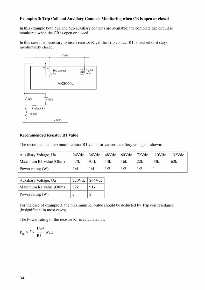
Examples 3: Trip Coil and Auxiliary Contacts Monitoring when CB is open or closed
In this example both 52a and 52b auxiliary contacts are available; the complete trip circuit is
monitored when the CB is open or closed.
In this case it is necessary to insert resistor R1, if the Trip contact R1 is latched or it stays
involuntarily closed.
Recommended Resistor R1 Value
The recommended maximum resistor R1 value for various auxiliary voltage is shown:
Auxiliary Voltage, Ua 24Vdc 36Vdc 48Vdc 60Vdc 72Vdc 110Vdc 132Vdc
Maximum R1 value (Ohm) 4.7k 9.1k 13k 16k 22k 43k 62k
Power rating (W) 1/4 1/4 1/2 1/2 1/2 1 1
Auxiliary Voltage, Ua 220Vdc 264Vdc
Maximum R1 value (Ohm) 82k 91k
Power rating (W) 2 2
For the case of example 3, the maximum R1 value should be deducted by Trip coil resistance
(insignificant in most cases).
The Power rating of the resistor R1 is calculated as:
PR1 > 2 x
R1
Ua 2
Watt
52a 52b
Resistor R1
- Vdc
Trip coil
+ Vdc
38 37
MK2200H
Trip contact
R1
DigitalInput
MK3000L
35
5.5 Disturbance Recorder
The disturbance recorder can be initiated by starting, tripping, input or remote (disturbance). The
total disturbance recording time is 6 records of 3 seconds, or 4 × 4s, or 3 × 5s, or 2 × 7s or 1 × 9s.
When the available memory space is used up, the new record automatically overwrites the oldest
record.
The pre-time is the length of time before the disturbance. For example if the pre-time time is set to
100ms, the record starts 100 ms before the disturbance.
Note: Changing the record length and number will result in deletion of existing records. If
necessary, read all wanted records before making changes.
The recorder stores actual samples that are taken at a rate of 32 samples per cycle. Each disturbance
record consists of 5 analogue and 7 digital channels.
5.6 Autoreclose
Autoreclose is used for clearing transient/non-permanent fault. Autoreclose can minimize power
blackout time and reduces the time and costs required for site servicing. With autoreclose,
instantaneous protection can be used, which shorten the time to clear a fault and minimize damages
and to reduce the number of permanent faults.
For recloser to function, the following setting is required:
1. One of the digital input function is CB Status 52A.
2. One of the output relay function is start/other, CB Close is assigned and reset method is auto
(unlatched)
3. Output Relay 1 (trip) reset method is auto (unlatched).
4. Reclose cycle assigned to phase or earth cycle (>0).
The phase cycle and earth cycle are used to set the number of shots (reclose attempts), recloser can
perform 2, 3 or 4 shot cycle. Dead times can be independently adjusted for each shots. The phase
cycle is applied for tAux1 and tAux2 tripping also.
CYCLE setting (for tI>, tI>>, tI>>>, tIo>, tIo>>, tIo>>>, tAux 1, tAux2):
0: Recloser will move to lock status after tripping.
1: Tripping, followed by reclosing cycle.
2: No trip of pickup.
The dead time starts when the CB has opened (52A input deactivates) and the involved protection
threshold reset. At the end of the relevant dead time, a CB close signal is sent. The reclaim time
starts when the CB has closed (52A input activates). If no tripping after reclaim time elapsed, the
recloser resets (reclose successful).
If tripping operates during reclaim time, the relay either advances to the next shot, or if all the
reclose attempts have been accomplished, the recloser locks out (recloser final trip). The recloser
will not be initiated for any fault during lockout.
CB Fail Alarm
If CB not open or close as expected for 2 seconds during reclose cycle, recloser locks out and CB
Fail alarm generated.
36
Lockout Reset
After lockout the CB can be closed by control close input, CB close button or remote CB close
command or by manual CB Close. The inhibit timer starts counting after CB close (52A input
activates). When the timer elapsed, lockout condition reset.
Block Autoreclose Input
If this input activate during reclose cycle , recloser locks out.
If activate when recloser not running, next tripping is definitive trip.
Other Notes
- During reclose cycle, Close CB button, control close by input and remote CB close command is
disabled. Open CB button and remote tripping command will lock the recloser.
- Maintenance mode will stop the reclose cycle without any locking. Power down the relay also
stops the reclose cycle.
- If the relay receives an order to change setting group, the order will only be executed after the
reclose cycle has elapsed.
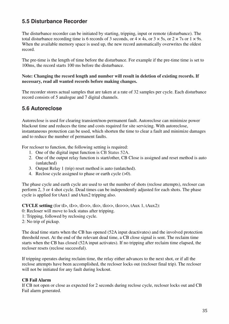
5.7 Open CB & Close CB Control
Open CB : To manually open circuit breaker
Close CB : To manually close circuit breaker
The Open CB and Close CB button allows circuit breaker (CB) to be opened and closed from the
relay front panel. Password is required for this operation. The control is available in the default
display. The control will work with or without CB Status 52A input. Open CB control is using
Output Relay 1 (Trip) for the signal.
For Open CB control, ‘Remote’ is assigned to output relay R1 or any other output relay with trip
function. Otherwise the display shows “Remote Trip output not found”
For Close CB control, one of the output relay function should be start/other and ‘CB Close’ is
assigned. Otherwise “CB close output not found” warning will be shown.
To Open CB
To open CB, press Open CB button once, password is required if not yet entered, then the display
shows “Press again to open CB…”, press Open CB button again to open the CB. Output relay 1
energize until CB Status 52A input deactivates. If CB Status 52A input is unavailable, Output relay
1 will energize for 2 seconds. The display shows “CB Opened” when CB opens successfully.
If Open CB button press but CB already opened (CB Status 52A input deactivates), the display
shows “CB is open” and ends.
To Close CB
To close CB, press Close CB button once, password is required if not yet entered. The display
shows “Press again to close CB…”, press Close CB button again to close the CB. Output relay for
CB Close energize until CB Status 52A input activates. If CB Status 52A input is unavailable,
Output relay will energize for 2 seconds. The display shows “CB Closed” when CB closes
successfully.
If Close CB button press but CB already closed (CB Status 52A input energizes), the display shows
“CB is close” and ends.
CB Fail Alarm
If CB Status 52A input is available and CB does not open or close after 2 seconds, CB Fail alarm
generated.
37
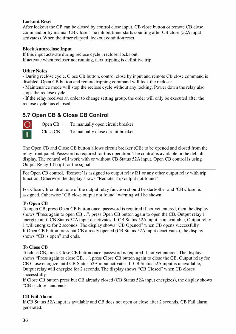
5.8 Characteristic Curves
1.00.90.80.70.60.5
0.4
0.3
0.2
0.1
0.05
Normal Inverse
Normal Inverse 1.3/10
Very Inverse
Long-time Inverse
38
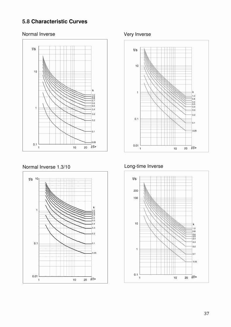
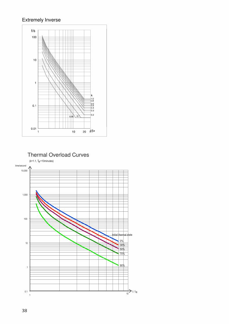
Extremely Inverse
(k=1.1, T =10minutes)
0.1
1
10
100
1,000
10,000
110
I / I
30%
50%
70%
90%
Initial thermal state
0%
time/second
Thermal Overload Curves
θ
θ
39
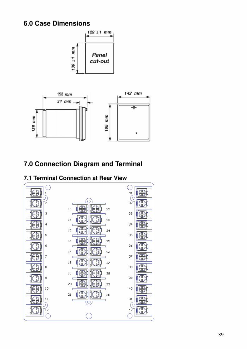
6.0 Case Dimensions
7.0 Connection Diagram and Terminal
7.1 Terminal Connection at Rear View
40
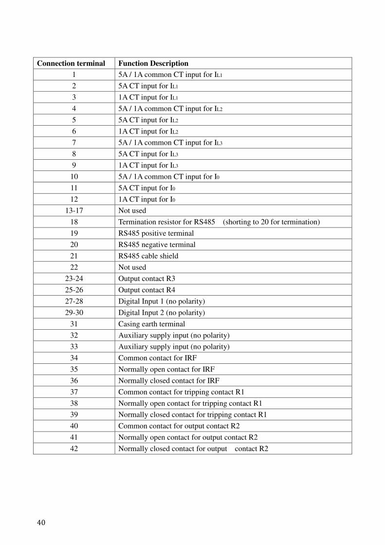
Connection terminal Function Description
1 5A / 1A common CT input for IL1
2 5A CT input for IL1
3 1A CT input for IL1
4 5A / 1A common CT input for IL2
5 5A CT input for IL2
6 1A CT input for IL2
7 5A / 1A common CT input for IL3
8 5A CT input for IL3
9 1A CT input for IL3
10 5A / 1A common CT input for I0
11 5A CT input for I0
12 1A CT input for I0
13-17 Not used
18 Termination resistor for RS485 (shorting to 20 for termination)
19 RS485 positive terminal
20 RS485 negative terminal
21 RS485 cable shield
22 Not used
23-24 Output contact R3
25-26 Output contact R4
27-28 Digital Input 1 (no polarity)
29-30 Digital Input 2 (no polarity)
31 Casing earth terminal
32 Auxiliary supply input (no polarity)
33 Auxiliary supply input (no polarity)
34 Common contact for IRF
35 Normally open contact for IRF
36 Normally closed contact for IRF
37 Common contact for tripping contact R1
38 Normally open contact for tripping contact R1
39 Normally closed contact for tripping contact R1
40 Common contact for output contact R2
41 Normally open contact for output contact R2
42 Normally closed contact for output contact R2
41
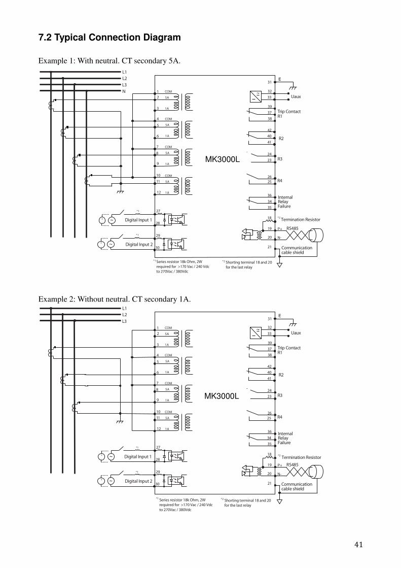
7.2 Typical Connection Diagram
Example 1: With neutral. CT secondary 5A.
3
2
1
6
5
4
9
8
7
12
11
10
27
28
39
37
38
24
23
26
25
36
34
35
21
20
18
19
Digital Input 1
RS485
Communicationcable shield
FailureRelayInternal
R1
R3
R4
L1
L2
L3
N
Trip Contact
P+
N-
42
40
41R2
32
33 Uaux
29
30
E
Shorting terminal 18 and 20
for the last relay
31
Series resistor 18k Ohm, 2W
required for >170 Vac / 240 Vdc
to 270Vac / 380Vdc
*1
*1 *2
*2
*1
+
-
+
-
5A
1A
COM
5A
1A
COM
5A
1A
COM
5A
1A
COM
Digital Input 2
Termination Resistor
Example 2: Without neutral. CT secondary 1A.
3
2
1
6
5
4
9
8
7
12
11
10
27
28
39
37
38
24
23
26
25
36
34
35
21
20
18
19 RS485
Communicationcable shield
FailureRelayInternal
R1
R3
R4
L1
L2
L3
Trip Contact
P+
N-
42
40
41R2
32
33 Uaux
29
30
E31
*1 *2
*2
*1
+
-
*1
+
-
5A
1A
COM
5A
1A
COM
5A
1A
COM
5A
1A
COM
Digital Input 1
Digital Input 2
Termination Resistor
Series resistor 18k Ohm, 2W
required for >170 Vac / 240 Vdc
to 270Vac / 380Vdc
Shorting terminal 18 and 20
for the last relay
MK3000L
MK3000L
42
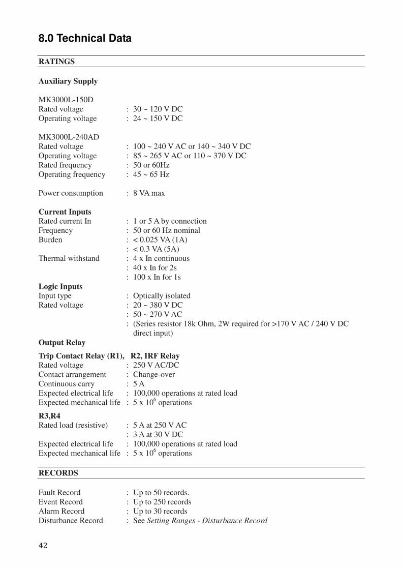
8.0 Technical Data
RATINGS
Auxiliary Supply
MK3000L-150D
Rated voltage : 30 ~ 120 V DC
Operating voltage : 24 ~ 150 V DC
MK3000L-240AD
Rated voltage : 100 ~ 240 V AC or 140 ~ 340 V DC
Operating voltage : 85 ~ 265 V AC or 110 ~ 370 V DC
Rated frequency : 50 or 60Hz
Operating frequency : 45 ~ 65 Hz
Power consumption : 8 VA max
Current Inputs
Rated current In : 1 or 5 A by connection
Frequency : 50 or 60 Hz nominal
Burden : < 0.025 VA (1A)
: < 0.3 VA (5A)
Thermal withstand : 4 x In continuous
: 40 x In for 2s
: 100 x In for 1s
Logic Inputs
Input type : Optically isolated
Rated voltage : 20 ~ 380 V DC
: 50 ~ 270 V AC
: (Series resistor 18k Ohm, 2W required for >170 V AC / 240 V DC
direct input)
Output Relay
Trip Contact Relay (R1), R2, IRF Relay
Rated voltage : 250 V AC/DC
Contact arrangement : Change-over
Continuous carry : 5 A
Expected electrical life : 100,000 operations at rated load
Expected mechanical life : 5 x 10⁶ operations
R3,R4
Rated load (resistive) : 5 A at 250 V AC
: 3 A at 30 V DC
Expected electrical life : 100,000 operations at rated load
Expected mechanical life : 5 x 10⁶ operations
RECORDS
Fault Record : Up to 50 records.
Event Record : Up to 250 records
Alarm Record : Up to 30 records
Disturbance Record : See Setting Ranges - Disturbance Record
43
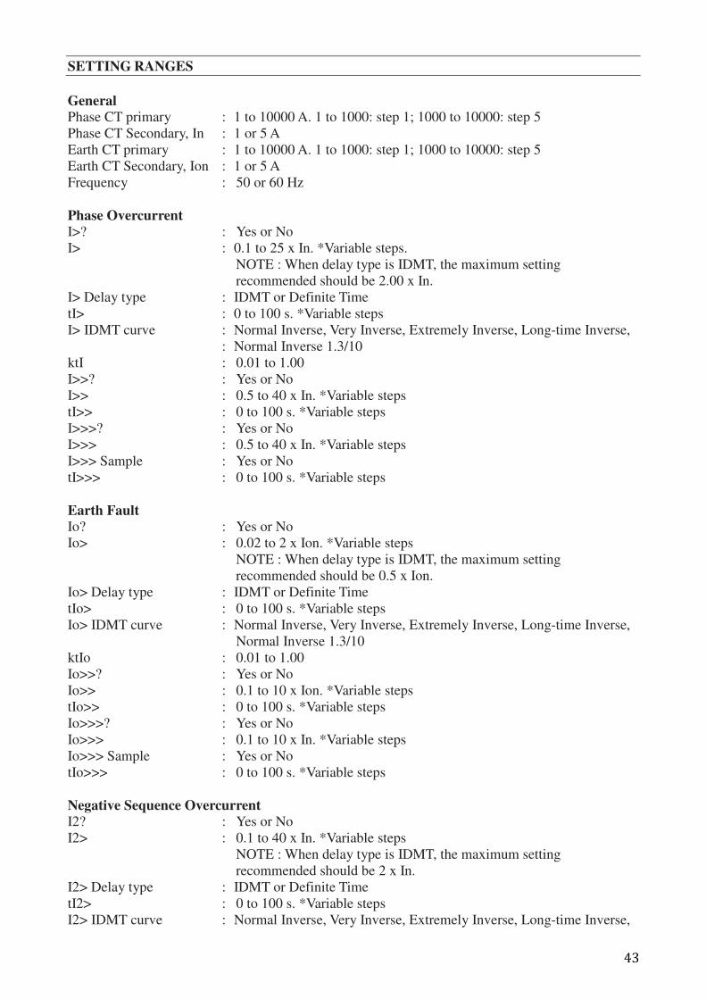
SETTING RANGES
General
Phase CT primary : 1 to 10000 A. 1 to 1000: step 1; 1000 to 10000: step 5
Phase CT Secondary, In : 1 or 5 A
Earth CT primary : 1 to 10000 A. 1 to 1000: step 1; 1000 to 10000: step 5
Earth CT Secondary, Ion : 1 or 5 A
Frequency : 50 or 60 Hz
Phase Overcurrent
I>? : Yes or No
I> : 0.1 to 25 x In. *Variable steps.
NOTE : When delay type is IDMT, the maximum setting
recommended should be 2.00 x In.
I> Delay type : IDMT or Definite Time
tI> : 0 to 100 s. *Variable steps
I> IDMT curve : Normal Inverse, Very Inverse, Extremely Inverse, Long-time Inverse,
: Normal Inverse 1.3/10
ktI : 0.01 to 1.00
I>>? : Yes or No
I>> : 0.5 to 40 x In. *Variable steps
tI>> : 0 to 100 s. *Variable steps
I>>>? : Yes or No
I>>> : 0.5 to 40 x In. *Variable steps
I>>> Sample : Yes or No
tI>>> : 0 to 100 s. *Variable steps
Earth Fault
Io? : Yes or No
Io> : 0.02 to 2 x Ion. *Variable steps
NOTE : When delay type is IDMT, the maximum setting
recommended should be 0.5 x Ion.
Io> Delay type : IDMT or Definite Time
tIo> : 0 to 100 s. *Variable steps
Io> IDMT curve : Normal Inverse, Very Inverse, Extremely Inverse, Long-time Inverse,
Normal Inverse 1.3/10
ktIo : 0.01 to 1.00
Io>>? : Yes or No
Io>> : 0.1 to 10 x Ion. *Variable steps
tIo>> : 0 to 100 s. *Variable steps
Io>>>? : Yes or No
Io>>> : 0.1 to 10 x In. *Variable steps
Io>>> Sample : Yes or No
tIo>>> : 0 to 100 s. *Variable steps
Negative Sequence Overcurrent
I2? : Yes or No
I2> : 0.1 to 40 x In. *Variable steps
NOTE : When delay type is IDMT, the maximum setting
recommended should be 2 x In.
I2> Delay type : IDMT or Definite Time
tI2> : 0 to 100 s. *Variable steps
I2> IDMT curve : Normal Inverse, Very Inverse, Extremely Inverse, Long-time Inverse,
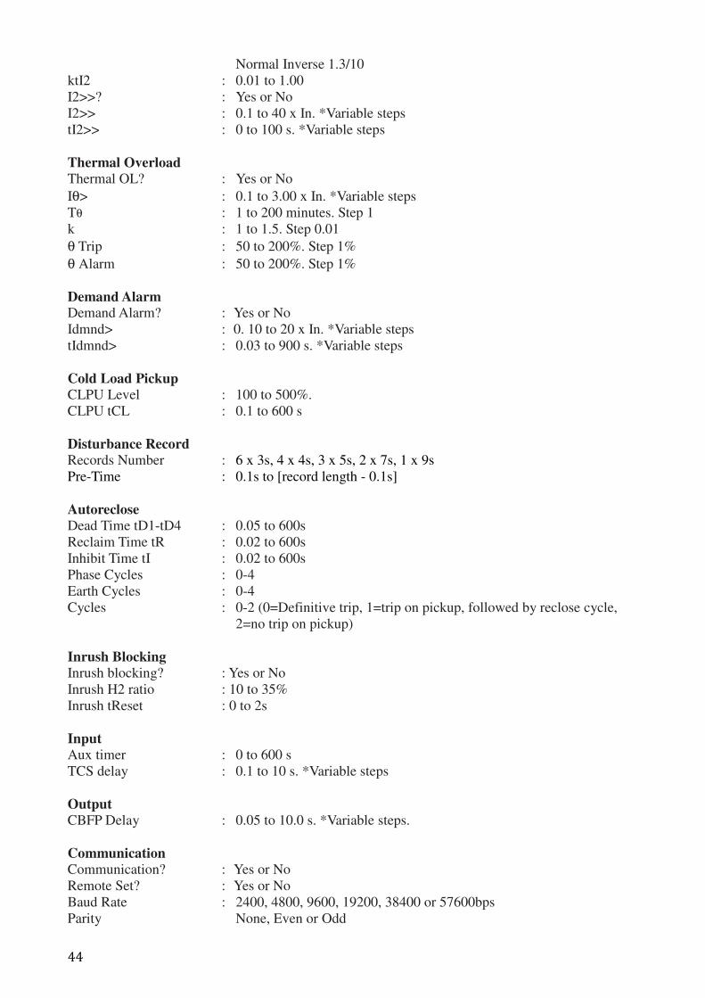
44
Normal Inverse 1.3/10
ktI2 : 0.01 to 1.00
I2>>? : Yes or No
I2>> : 0.1 to 40 x In. *Variable steps
tI2>> : 0 to 100 s. *Variable steps
Thermal Overload
Thermal OL? : Yes or No
Iθ> : 0.1 to 3.00 x In. *Variable steps
Tθ : 1 to 200 minutes. Step 1
k : 1 to 1.5. Step 0.01
θ Trip : 50 to 200%. Step 1%
θ Alarm : 50 to 200%. Step 1%
Demand Alarm Demand Alarm? : Yes or No
Idmnd> : 0. 10 to 20 x In. *Variable steps
tIdmnd> : 0.03 to 900 s. *Variable steps
Cold Load Pickup
CLPU Level : 100 to 500%.
CLPU tCL : 0.1 to 600 s
Disturbance Record
Records Number : 6 x 3s, 4 x 4s, 3 x 5s, 2 x 7s, 1 x 9s
Pre-Time : 0.1s to [record length - 0.1s]
Autoreclose
Dead Time tD1-tD4 : 0.05 to 600s
Reclaim Time tR : 0.02 to 600s
Inhibit Time tI : 0.02 to 600s
Phase Cycles : 0-4
Earth Cycles : 0-4
Cycles : 0-2 (0=Definitive trip, 1=trip on pickup, followed by reclose cycle,
2=no trip on pickup)
Inrush Blocking
Inrush blocking? : Yes or No
Inrush H2 ratio : 10 to 35%
Inrush tReset : 0 to 2s
Input
Aux timer : 0 to 600 s
TCS delay : 0.1 to 10 s. *Variable steps
Output
CBFP Delay : 0.05 to 10.0 s. *Variable steps.
Communication
Communication? : Yes or No
Remote Set? : Yes or No
Baud Rate : 2400, 4800, 9600, 19200, 38400 or 57600bps
Parity None, Even or Odd
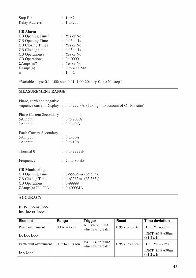
45
Stop Bit : 1 or 2
Relay Address : 1 to 255
CB Alarm
CB Opening Time? : Yes or No
CB Opening Time : 0.05 to 1s
CB Closing Time? : Yes or No
CB Closing time : 0.05 to 1s
CB Operations? : Yes or No
CB Operations : 0-10000
ΣAmps(n)? : Yes or No
ΣAmps(n) : 0 to 4000MA
n : 1 or 2
*Variable steps: 0.1-1.00: step 0.01; 1.00-20: step 0.1; >20: step 1
MEASUREMENT RANGE
Phase, earth and negative
sequence current Display : 0 to 999 kA. (Taking into account of CT Pri ratio)
Phase Current Secondary
5A input : 0 to 200 A
1A input : 0 to 40 A
Earth Current Secondary
5A input : 0 to 50A
1A input : 0 to 10A
Thermal θ : 0 to 9999%
Frequency : 20 to 80 Hz
CB Monitoring
CB Opening Time : 0-65535ms (65.535s)
CB Closing Time : 0-65535ms (65.535s)
CB Operations : 0-99999
ΣAmps(n) IL1-IL3 : 0-4000MA
ACCURACY
Is: I>, I>> or I>>>
Ios: Io> or Io>>
Element Range Trigger Reset Time deviation
Phase overcurrent 0.1 to 40 x In Is ± 3% or 30mA
whichever greater 0.95 x Is ± 2% DT: ±2% +30ms
I>, I>>, I>>> IDMT: ±5% +30ms
(>1.2 x Is)
Earth fault overcurrent 0.02 to 10 x Ion Ios ± 3% or 30mA
whichever greater 0.95 x Ios ± 2% DT: ±2% +30ms
Io>, Io>> IDMT: ±5% +30ms
(>1.2 x Is)
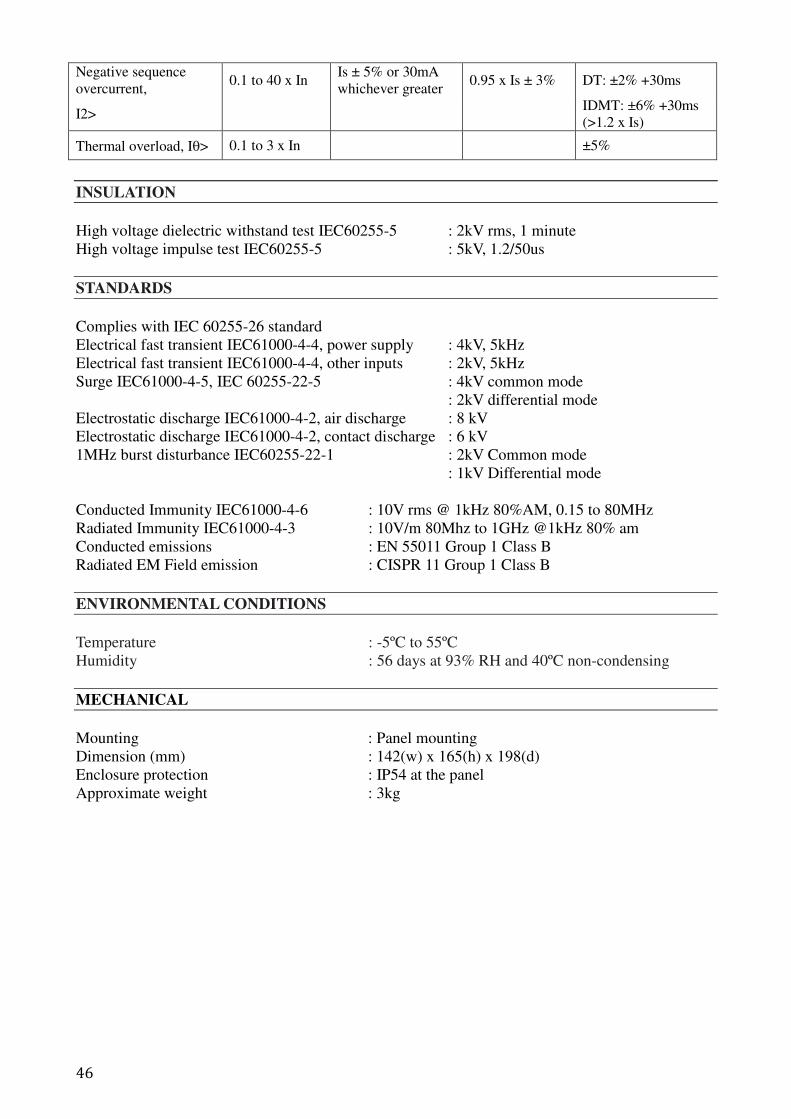
46
Negative sequence
overcurrent, 0.1 to 40 x In
Is ± 5% or 30mA
whichever greater 0.95 x Is ± 3% DT: ±2% +30ms
I2> IDMT: ±6% +30ms
(>1.2 x Is)
Thermal overload, Iθ> 0.1 to 3 x In ±5%
INSULATION
High voltage dielectric withstand test IEC60255-5 : 2kV rms, 1 minute
High voltage impulse test IEC60255-5 : 5kV, 1.2/50us
STANDARDS
Complies with IEC 60255-26 standard
Electrical fast transient IEC61000-4-4, power supply : 4kV, 5kHz
Electrical fast transient IEC61000-4-4, other inputs : 2kV, 5kHz
Surge IEC61000-4-5, IEC 60255-22-5 : 4kV common mode
: 2kV differential mode
Electrostatic discharge IEC61000-4-2, air discharge : 8 kV
Electrostatic discharge IEC61000-4-2, contact discharge : 6 kV
1MHz burst disturbance IEC60255-22-1 : 2kV Common mode
: 1kV Differential mode
Conducted Immunity IEC61000-4-6 : 10V rms @ 1kHz 80%AM, 0.15 to 80MHz
Radiated Immunity IEC61000-4-3 : 10V/m 80Mhz to 1GHz @1kHz 80% am
Conducted emissions : EN 55011 Group 1 Class B
Radiated EM Field emission : CISPR 11 Group 1 Class B
ENVIRONMENTAL CONDITIONS
Temperature : -5ºC to 55ºC
Humidity : 56 days at 93% RH and 40ºC non-condensing
MECHANICAL
Mounting : Panel mounting
Dimension (mm) : 142(w) x 165(h) x 198(d)
Enclosure protection : IP54 at the panel
Approximate weight : 3kg
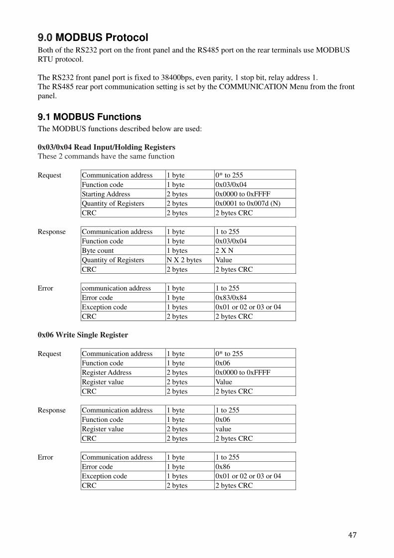
47
9.0 MODBUS Protocol Both of the RS232 port on the front panel and the RS485 port on the rear terminals use MODBUS
RTU protocol.
The RS232 front panel port is fixed to 38400bps, even parity, 1 stop bit, relay address 1.
The RS485 rear port communication setting is set by the COMMUNICATION Menu from the front
panel.
9.1 MODBUS Functions
The MODBUS functions described below are used:
0x03/0x04 Read Input/Holding Registers
These 2 commands have the same function
Request Communication address 1 byte 0* to 255
Function code 1 byte 0x03/0x04
Starting Address 2 bytes 0x0000 to 0xFFFF
Quantity of Registers 2 bytes 0x0001 to 0x007d (N)
CRC 2 bytes 2 bytes CRC
Response Communication address 1 byte 1 to 255
Function code 1 byte 0x03/0x04
Byte count 1 bytes 2 X N
Quantity of Registers N X 2 bytes Value
CRC 2 bytes 2 bytes CRC
Error communication address 1 byte 1 to 255
Error code 1 byte 0x83/0x84
Exception code 1 bytes 0x01 or 02 or 03 or 04
CRC 2 bytes 2 bytes CRC
0x06 Write Single Register
Request Communication address 1 byte 0* to 255
Function code 1 byte 0x06
Register Address 2 bytes 0x0000 to 0xFFFF
Register value 2 bytes Value
CRC 2 bytes 2 bytes CRC
Response Communication address 1 byte 1 to 255
Function code 1 byte 0x06
Register value 2 bytes value
CRC 2 bytes 2 bytes CRC
Error Communication address 1 byte 1 to 255
Error code 1 byte 0x86
Exception code 1 bytes 0x01 or 02 or 03 or 04
CRC 2 bytes 2 bytes CRC
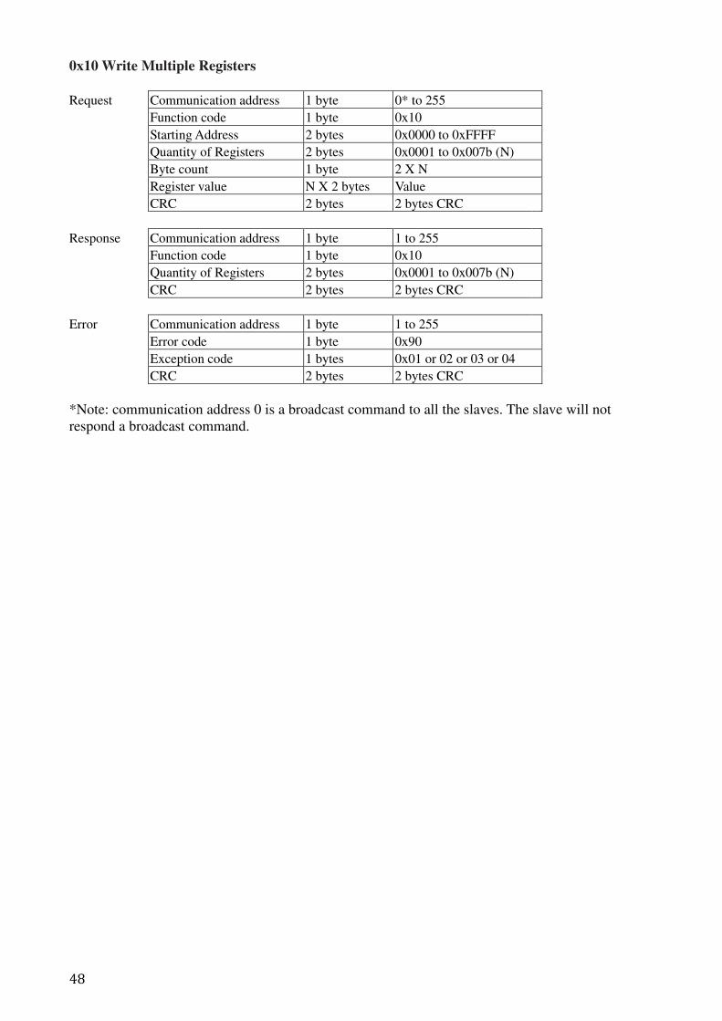
48
0x10 Write Multiple Registers
Request Communication address 1 byte 0* to 255
Function code 1 byte 0x10
Starting Address 2 bytes 0x0000 to 0xFFFF
Quantity of Registers 2 bytes 0x0001 to 0x007b (N)
Byte count 1 byte 2 X N
Register value N X 2 bytes Value
CRC 2 bytes 2 bytes CRC
Response Communication address 1 byte 1 to 255
Function code 1 byte 0x10
Quantity of Registers 2 bytes 0x0001 to 0x007b (N)
CRC 2 bytes 2 bytes CRC
Error Communication address 1 byte 1 to 255
Error code 1 byte 0x90
Exception code 1 bytes 0x01 or 02 or 03 or 04
CRC 2 bytes 2 bytes CRC
*Note: communication address 0 is a broadcast command to all the slaves. The slave will not
respond a broadcast command.
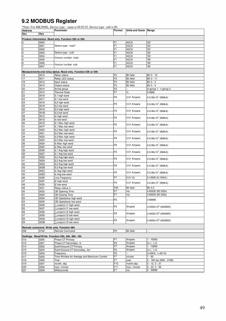
49
9.2 MODBUS Register *Note: For MK3000L, Device type – main is 00 02 03. Device type –sub is 00.
Dec Hex
Product information. Read only. Function 03h or 04h
0 0000 F1 ASCII '00'
1 0001 F1 ASCII '02'
2 0002 F1 ASCII '03'
3 0003 Device type - sub* F1 ASCII '00'
4 0004 F1 ASCII 'XX'
5 0005 F1 ASCII 'XX'
6 0006 F1 ASCII 'XX'
7 0007 F1 ASCII 'XX'
Measurements and relay status. Read only. Function 03h or 04h
16 0010 Relay status F2 Bit field Bit 0 - 15
17 0011 Relay LED status F3 Bit field Bit 0 - 11
18 0012 Input status F4 Bit field Bit 0 - 3
19 0013 Output status F5 Bit field Bit 0 - 4
20 0014 Active group F6 -- 0=group 1, 1=group 2
21 0015 Thermal State F7 % 0-9999
22 0016 IL1 high word
23 0017 IL1 low word
24 0018 IL2 high word
25 0019 IL2 low word
26 001A IL3 high word
27 001B IL3 low word
28 001C Io high word
29 001D Io low word
30 001E IL1 Max high word
31 001F IL1 Max low word
32 0020 IL2 Max high word
33 0021 IL2 Max low word
34 0022 IL3 Max high word
35 0023 IL3 Max low word
36 0024 Io Max high word
37 0025 Io Max low word
38 0026 IL1 Avg high word
39 0027 IL1 Avg low word
40 0028 IL2 Avg high word
41 0029 IL2 Avg low word
42 002A IL3 Avg high word
43 002B IL3 Avg low word
44 002C Io Avg high word
45 002D Io Avg low word
46 002E Line Frequency F7 0.01 Hz 0-10000 (0-100Hz)
47 002F I2 high word
48 0030 I2 low word
49 0031 Relay status 2 F25 Bit field Bit 0-2
50 0032 CB Opening Time F7 ms 0-65535 (65.535s)
51 0033 CB Closing Time F7 ms 0-65535 (65.535s)
52 0034 CB Operations high word
53 0035 CB Operations low word
54 0036 ∑Αmps(n) I1 high word
55 0037 ∑Αmps(n) I1 low word
56 0038 ∑Αmps(n) I2 high word
57 0039 ∑Αmps(n) I2 low word
58 003A ∑Αmps(n) I3 high word
59 003B ∑Αmps(n) I3 low word
Remote command. Write only. Function 06h
256 0100 Remote Command F9 Bit field --
Settings. Read/Write. Function 03h, 04h, 06h, 10h
512 0200 Phase CT Primary F7 Ampere 1 - 10000
513 0201 Phase CT Secondary, In F6 Ampere 0=1, 1=5
514 0202 Earth/Ground CT Primary F7 Ampere 1 - 10000
515 0203 Earth/Ground CT Secondary, Ion F6 Ampere 0=1, 1=5
516 0204 Frequency F6 -- 0=50Hz, 1=60 Hz
517 0205 Time Window for Average and Maximum Current F7 minute 1 - 60
518 0206 Year F7 year 0 - 199 (as 2000 - 2199)
519 0207 month, day F10 month,day 0 - 12, 0 - 31
520 0208 hour, minute F11 hour, minute 0 - 23, 0 - 59
521 0209 Milliseconds F7 ms 0 - 59999
Address Parameter Format Units and Scale Range
Device type - main*
Version number -main
Version number -sub
F8 0.01 Ampere 0-9.99x10⁷ (999kA)
F8 0.01 Ampere 0-9.99x10⁷ (999kA)
F8 0.01 Ampere 0-9.99x10⁷ (999kA)
F8 0.01 Ampere 0-9.99x10⁷ (999kA)
F8 0.01 Ampere 0-9.99x10⁷ (999kA)
F8 0.01 Ampere 0-9.99x10⁷ (999kA)
F8 0.01 Ampere 0-9.99x10⁷ (999kA)
F8 0.01 Ampere 0-9.99x10⁷ (999kA)
F8 0.01 Ampere 0-9.99x10⁷ (999kA)
F8 0.01 Ampere 0-9.99x10⁷ (999kA)
F8 0.01 Ampere 0-9.99x10⁷ (999kA)
F8 0.01 Ampere 0-9.99x10⁷ (999kA)
F8 0.01 Ampere 0-9.99x10⁷ (999kA)
F8 -- 0-99999
F8 Ampere 0-4000x106 (4000MA)
F8 Ampere 0-4000x106 (4000MA)
F8 Ampere 0-4000x106 (4000MA)
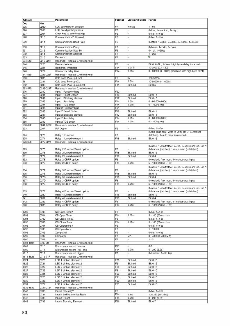
50
Dec Hex
525 020D LCD backlight on duration F7 minute 1 - 60
526 020E LCD backlight brightness F6 -- 0=low, 1=medium, 2=high
527 020F Clear' key to scroll settings F6 -- 0=No, 1=Yes
528 0210 Communication? (Unused) F6 -- 0=No, 1=Yes
529 0211 Communication Baud Rate F6 -- 0=2400, 1=4800, 2=9600, 3=19200, 4=38400
530 0212 Communication Parity F6 -- 0=None, 1=Odd, 2=Even
531 0213 Communication Stop Bit F6 -- 0=1bit, 1=2bits
532 0214 Communication Address F7 -- 1 - 255
533 0215 Password F7 -- 0
534-543 0216-021F Reserved - read as 0, write to void
544 0220 Demand Alarm F6 -- Bit 0: 0=No, 1=Yes. High byte=delay time msb
545 0221 Idemand> threshold F14 0.01 In 10-2000 (0.1 - 20)
546 0222 tIdemand> delay time F14 0.01s 0 - 90000 (0 - 900s) (combine with high byte 0221)
547-559 0223-022F Reserved - read as 0, write to void
560 0230 Cold Load Pick-up Level F7 % 100-500%
561 0231 Cold Load Pick-up tCL F14 0.01s 10-60000 (0.1-600s)
562 0232 Cold Load Pick-up element F15 Bit field Bit 0-5
563-575 0233-023F Reserved - read as 0, write to void
576 0240 Input 1 Function/Type F22 -- --
577 0241 Input 1 Reset Option F16 Bit field Bit 0 - 1
578 0242 Input 1 Blocking element F17 Bit field Bit 0 - 5
579 0243 Input 1 Aux delay F14 0.01s 0 - 60,000 (600s)
580 0244 Input 1 TCS delay F14 0.01s 0 - 1000 (10s)
581 0245 Input 2 Function/Type F21 -- --
582 0246 Input 2 Reset Option F16 Bit field Bit 0 - 1
583 0247 Input 2 Blocking element F17 Bit field Bit 0 - 5
584 0248 Input 2 Aux delay F14 0.01s 0 - 60,000 (600s)
585 0249 Input 2 TCS delay F14 0.01s 0 - 1000 (10s)
586-622 024A-026E Reserved - read as 0, write to void
623 026F IRF Option F6 -- 0=No, 1=Yes
624 0270 Relay 1 Function F6 --
2=trip (read only, write to void). Bit 7: 0=Manual
(latched), 1=auto reset (unlatched)
625 0271 Relay 1 Linked element 1 F18 Bit field Bit 0-13
626-628 0272-0274 Reserved - read as 0, write to void
629 0275 Relay 2 Function/Reset option F6 --
0=none, 1=start/other, 2=trip, 3=upstream trip. Bit 7:
0=Manual (latched), 1=auto reset (unlatched)
630 0276 Relay 2 Linked element 1 F18 Bit field Bit 0-13
631 0277 Relay 2 Linked element 2 F19 Bit field Bit 0-4
632 0278 Relay 2 CBFP option F6 -- 0=exclude Aux input, 1=include Aux input
633 0279 Relay 2 CBFP delay F14 0.01s 5 - 1000 (50ms - 10s)
634 027A Relay 3 Function/Reset option F6 --
0=none, 1=start/other, 2=trip, 3=upstream trip. Bit 7:
0=Manual (latched), 1=auto reset (unlatched)
635 027B Relay 3 Linked element 1 F18 Bit field Bit 0-13
636 027C Relay 3 Linked element 2 F19 Bit field Bit 0-4
637 027D Relay 3 CBFP option F6 -- 0=exclude Aux input, 1=include Aux input
638 027E Relay 3 CBFP delay F14 0.01s 5 - 1000 (50ms - 10s)
639 027F Relay 4 Function/Reset option F6 --
0=none, 1=start/other, 2=trip, 3=upstream trip. Bit 7:
0=Manual (latched), 1=auto reset (unlatched)
640 0280 Relay 4 Linked element 1 F18 Bit field Bit 0-13
641 0281 Relay 4 Linked element 2 F19 Bit field Bit 0-4
642 0282 Relay 4 CBFP option F6 -- 0=exclude Aux input, 1=include Aux input
643 0283 Relay 4 CBFP delay F14 0.01s 5 - 1000 (50ms - 10s)
1792 0700 CB Open Time? F6 -- 0=No, 1=Yes
1793 0701 CB Open Time F14 0.01s 5 - 100 (50ms - 1s)
1794 0702 CB Close Time? F6 -- 0=No, 1=Yes
1795 0703 CB Close Time F14 0.01s 5 - 100 (50ms - 1s)
1796 0704 CB Operations? F6 -- 0=No, 1=Yes
1797 0705 CB Operations F7 -- 1 - 10000
1798 0706 Σamps(n)? F6 -- 0=No, 1=Yes
1799 0707 Σamps(n) F7 MA 0 - 4000 (0-4000MA)
1800 0708 n F7 -- 1 - 2
1801-1807 0709-70F Reserved - read as 0, write to void
1808 0710 Disturbance record number F23 -- 0-5
1809 0711 Disturbance record Pre-Time F14 0.01s 0 - 290 (2.9s)
1810 0712 Disturbance record trigger F6 -- 0=On Inst, 1=On Trip
1811-1823 0713-71F Reserved - read as 0, write to void
1824 0720 LED 1 Linked element 1 F20 Bit field Bit 0-15
1825 0721 LED 1 Linked element 2 F21 Bit field Bit 0-15
1826 0722 LED 2 Linked element 1 F20 Bit field Bit 0-15
1827 0723 LED 2 Linked element 2 F21 Bit field Bit 0-15
1828 0724 LED 3 Linked element 1 F20 Bit field Bit 0-15
1829 0725 LED 3 Linked element 2 F21 Bit field Bit 0-15
1830 0726 LED 4 Linked element 1 F20 Bit field Bit 0-15
1831 0727 LED 4 Linked element 2 F21 Bit field Bit 0-15
1832-1839 0727-072F Reserved - read as 0, write to void
1840 0730 Inrush Blocking? F6 -- 0=No, 1=Yes
1841 0731 Inrush 2nd Harmonics Ratio F14 0.1% 100-350 (10-35%)
1842 0732 Inrush tReset F14 0.01s 0 - 200 (0-2s)
1843 0733 Inrush Blocking Element F26 Bit field Bit 0-7
Address Parameter Format Units and Scale Range
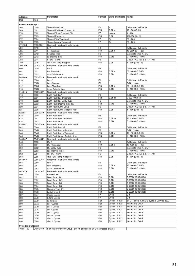
51
Dec Hex
Protection Group 1
768 0300 Thermal Overload? F6 -- 0=Disable, 1=Enable
769 0301 Thermal Full Load Current, Iθ F14 0.01 In 10 - 300 (0.1-3)
770 0302 Thermal Time Constant, Tθ F7 minute 1 - 200
771 0303 Thermal Factor, k F14 0.01 100-150 (1-1.5)
772 0304 Thermal Trip Threshold F7 % 50 - 200
773 0305 Thermal Alarm Threshold F7 % 50 - 200
774-783 0306-030F Reserved - read as 0, write to void
784 0310 I> ? F6 -- 0=Disable, 1=Enable
785 0311 I> Threshold F14 0.01 In 10-2500 (0.1 - 25)
786 0312 I> Delay Type F6 -- 0=definite time, 1=IDMT
787 0313 tI> Definite Time F14 0.01s 0 - 10000 (0 - 100s)
788 0314 I> IDMT Curve F6 -- 0=NI,1=VI,2=EI, 3=LTI, 4=NI1
789 0315 ktI> IDMT time multiplier F14 0.01 1 - 100 (0.01 - 1)
790-799 0316-031F Reserved - read as 0, write to void
800 0320 I>> ? F6 -- 0=Disable, 1=Enable
801 0321 I>> Threshold F14 0.01 In 50 - 4000 (0.5-40)
802 0322 tI>> Definite time F14 0.01s 0 - 10000 (0 - 100s)
803-809 0323-0329 Reserved - read as 0, write to void
810 032A I>>>? F6 -- 0=Disable, 1=Enable
811 032B I>>> Sample F6 -- 0=No, 1=Yes
812 032C I>>> Threshold F14 0.01 In 50 - 4000 (0.5-40)
813 032D tI>>> Definite time F14 0.01s 0 - 10000 (0 - 100s)
814-815 032E-032F Reserved - read as 0, write to void
816 0330 Earth Fault Io>? F6 -- 0=Disable, 1=Enable
817 0331 Earth Fault Io> Threshold F14 0.01 Ion 2-200 (0.02 - 2)
818 0332 Earth Fault Io> Delay Type F6 -- 0=definite time, 1=IDMT
819 0333 Earth Fault Definite Time tIo> F14 0.01s 0 - 10000 (0 - 100s)
820 0334 Earth Fault IDMT Curve F6 -- 0=NI,1=VI,2=EI, 3=LTI, 4=NI1
821 0335 Earth Fault IDMT Multiplier kto> F14 0.01 1 - 100 (0.01 - 1)
822-831 0336-0339 Reserved - read as 0, write to void
832 0340 Earth Fault Io>>? F6 -- 0=Disable, 1=Enable
833 0341 Earth Fault Io>> Threshold F14 0.01 Ion 10 - 1000 (0.1-10)
834 0342 Earth Fault tIo>> F14 0.01s 0 - 10000 (0 - 100s)
835-841 0343-0349 Reserved - read as 0, write to void
842 034A Earth Fault Io>>>? F6 -- 0=Disable, 1=Enable
843 034B Earth Fault Io>>> Sample F6 -- 0=No, 1=Yes
844 034C Earth Fault Io>>> Threshold F14 0.01 In 10 - 1000 (0.1-10)
845 034D Earth Fault tIo>>> Definite time F14 0.01s 0 - 10000 (0 - 100s)
846-847 034E-034F Reserved - read as 0, write to void
848 0350 I2> ? F6 -- 0=Disable, 1=Enable
849 0351 I2> Threshold F14 0.01 In 10-4000 (0.1 - 40)
850 0352 I2> Delay Type F6 -- 0=definite time, 1=IDMT
851 0353 tI2> Definite Time F14 0.01s 0 - 10000 (0 - 100s)
852 0354 I2> IDMT Curve F6 -- 0=NI,1=VI,2=EI, 3=LTI, 4=NI1
853 0355 ktI2> IDMT time multiplier F14 0.01 1 - 100 (0.01 - 1)
854-863 0356-035F Reserved - read as 0, write to void
864 0360 I2>> ? F6 -- 0=Disable, 1=Enable
865 0361 I2>> Threshold F14 0.01 In 10 - 4000 (0.1-40)
866 0362 tI2>> Definite time F14 0.01s 0 - 10000 (0 - 100s)
867-879 0363-036F Reserved - read as 0, write to void
880 0370 Autoreclose? F6 -- 0=Disable, 1=Enable
881 0371 Dead Time, tD1 F14 0.01s 5-60000 (0.05-600s)
882 0372 Dead Time, tD2 F14 0.01s 5-60000 (0.05-600s)
883 0373 Dead Time, tD3 F14 0.01s 5-60000 (0.05-600s)
884 0374 Dead Time, tD4 F14 0.01s 5-60000 (0.05-600s)
885 0375 Reclaim Time, tR F14 0.01s 2-60000 (0.02-600s)
886 0376 Inhibit Time, tI F14 0.01s 2-60000 (0.02-600s)
887 0377 Phase Cycles F7 Cycle 0-4
888 0378 E/Gnd Cycles F7 Cycle 0-4
889 0379 tI> Cycles F24 Cycles 4 3 2 1 bit 0-1: cycle 1, bit 2-3 cycle 2, 0000 to 2222
890 037A tI>> Cycles F24 Cycles 4 3 2 1 Hex 0x0 to 0xAA
891 037B tI>>> Cycles F24 Cycles 4 3 2 1 Hex 0x0 to 0xAA
892 037C tIo> Cycles F24 Cycles 4 3 2 1 Hex 0x0 to 0xAA
893 037D tIo>> Cycles F24 Cycles 4 3 2 1 Hex 0x0 to 0xAA
894 037E tIo>>> Cycles F24 Cycles 4 3 2 1 Hex 0x0 to 0xAA
895 037F tAux 1 Cycles F24 Cycles 4 3 2 1 Hex 0x0 to 0xAA
896 0380 tAux 2 Cycles F24 Cycles 4 3 2 1 Hex 0x0 to 0xAA
Protection Group 2
1024-1152 0400-0480 Same as Protection Group1 except addresses are 04xx instead of 03xx
Address Parameter Format Units and Scale Range
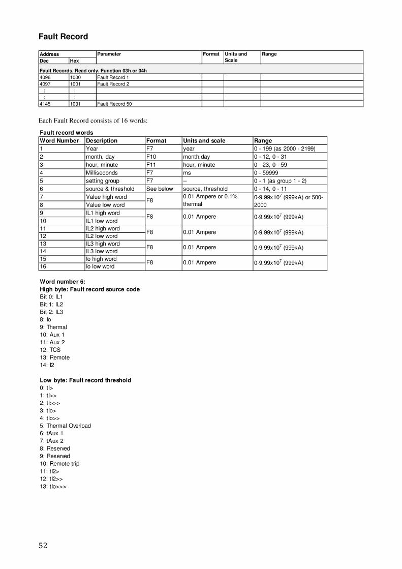
52
Fault Record
Dec Hex
Fault Records. Read only. Function 03h or 04h
4096 1000 Fault Record 1
4097 1001 Fault Record 2
: :
: :
4145 1031 Fault Record 50
Address Parameter Format Units and
Scale
Range
Each Fault Record consists of 16 words:
Fault record words
Word Number Description Format Units and scale Range
1 Year F7 year 0 - 199 (as 2000 - 2199)
2 month, day F10 month,day 0 - 12, 0 - 31
3 hour, minute F11 hour, minute 0 - 23, 0 - 59
4 Milliseconds F7 ms 0 - 59999
5 setting group F7 -- 0 - 1 (as group 1 - 2)
6 source & threshold See below source, threshold 0 - 14, 0 - 11
7 Value high word
8 Value low word
9 IL1 high word
10 IL1 low word
11 IL2 high word
12 IL2 low word
13 IL3 high word
14 IL3 low word
15 Io high word
16 Io low word
Word number 6:
High byte: Fault record source code
Bit 0: IL1
Bit 1: IL2
Bit 2: IL3
8: Io
9: Thermal
10: Aux 1
11: Aux 2
12: TCS
13: Remote
14: I2
Low byte: Fault record threshold
0: tI>
1: tI>>
2: tI>>>
3: tIo>
4: tIo>>
5: Thermal Overload
6: tAux 1
7: tAux 2
8: Reserved
9: Reserved
10: Remote trip
11: tI2>
12: tI2>>
13: tIo>>>
0-9.99x10⁷ (999kA) or 500-
2000
0-9.99x10⁷ (999kA)0.01 Ampere
0.01 Ampere 0-9.99x10⁷ (999kA)
F8 0.01 Ampere 0-9.99x10⁷ (999kA)
F8
F8
F8
F8 0.01 Ampere 0-9.99x10⁷ (999kA)
0.01 Ampere or 0.1%
thermal
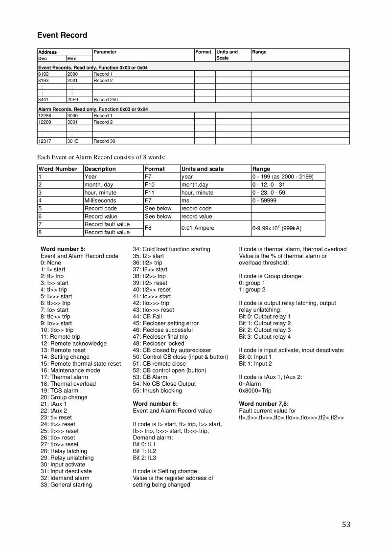
53
Event Record
Dec Hex
Event Records. Read only. Function 0x03 or 0x04
8192 2000 Record 1
8193 2001 Record 2
: :
: :
8441 20F9 Record 250
Alarm Records. Read only. Function 0x03 or 0x04
12288 3000 Record 1
12289 3001 Record 2
: :
: :
12317 301D Record 30
Address Parameter Format Units and
Scale
Range
Each Event or Alarm Record consists of 8 words:
Word Number Description Format Units and scale Range
1 Year F7 year 0 - 199 (as 2000 - 2199)
2 month, day F10 month,day 0 - 12, 0 - 31
3 hour, minute F11 hour, minute 0 - 23, 0 - 59
4 Milliseconds F7 ms 0 - 59999
5 Record code See below record code
6 Record value See below record value
7 Record fault value
8 Record fault value0-9.99x10⁷ (999kA)F8 0.01 Ampere
Word number 5: Event and Alarm Record code 0: None 1: I> start 2: tI> trip 3: I>> start 4: tI>> trip 5: I>>> start 6: tI>>> trip 7: Io> start 8: tIo>> trip 9: Io>> start 10: tIo>> trip 11: Remote trip 12: Remote acknowledge 13: Remote reset 14: Setting change 15: Remote thermal state reset 16: Maintenance mode 17: Thermal alarm 18: Thermal overload 19: TCS alarm 20: Group change 21: tAux 1 22: tAux 2 23: tI> reset 24: tI>> reset 25: tI>>> reset 26: tIo> reset 27: tIo>> reset 28: Relay latching 29: Relay unlatching 30: Input activate 31: Input deactivate 32: Idemand alarm 33: General starting
34: Cold load function starting 35: I2> start 36: tI2> trip 37: I2>> start 38: tI2>> trip 39: tI2> reset 40: tI2>> reset 41: Io>>> start 42: tIo>>> trip 43: tIo>>> reset 44: CB Fail 45: Recloser setting error 46: Reclose successful 47: Recloser final trip 48: Recloser locked 49: CB closed by autorecloser 50: Control CB close (input & button) 51: CB remote close 52: CB control open (button) 53: CB Alarm 54: No CB Close Output 55: Inrush blocking Word number 6: Event and Alarm Record value If code is I> start, tI> trip, I>> start, tI>> trip, I>>> start, tI>>> trip, Demand alarm: Bit 0: IL1 Bit 1: IL2 Bit 2: IL3 If code is Setting change: Value is the register address of setting being changed
If code is thermal alarm, thermal overload Value is the % of thermal alarm or overload threshold: If code is Group change: 0: group 1 1: group 2 If code is output relay latching, output relay unlatching: Bit 0: Output relay 1 Bit 1: Output relay 2 Bit 2: Output relay 3 Bit 3: Output relay 4 If code is input activate, input deactivate: Bit 0: Input 1 Bit 1: Input 2 If code is tAux 1, tAux 2: 0=Alarm 0x8000=Trip Word number 7,8: Fault current value for tI>,tI>>,tI>>>,tIo>,tIo>>,tIo>>>,tI2>,tI2>>
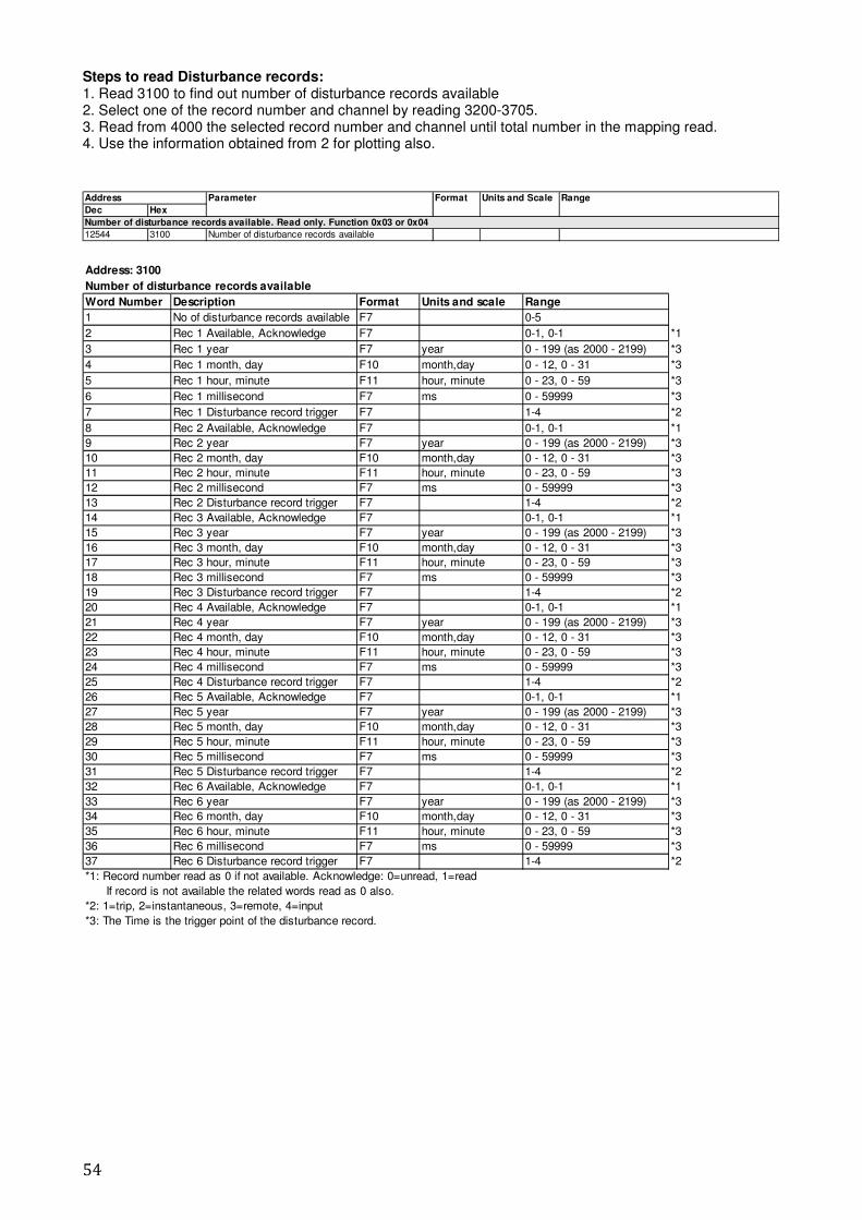
54
Steps to read Disturbance records: 1. Read 3100 to find out number of disturbance records available 2. Select one of the record number and channel by reading 3200-3705. 3. Read from 4000 the selected record number and channel until total number in the mapping read. 4. Use the information obtained from 2 for plotting also.
Dec Hex
Number of disturbance records available. Read only. Function 0x03 or 0x04
12544 3100 Number of disturbance records available
Address Parameter Format Units and Scale Range
Address: 3100
Number of disturbance records available
Word Number Description Format Units and scale Range
1 No of disturbance records available F7 0-5
2 Rec 1 Available, Acknowledge F7 0-1, 0-1 *1
3 Rec 1 year F7 year 0 - 199 (as 2000 - 2199) *3
4 Rec 1 month, day F10 month,day 0 - 12, 0 - 31 *3
5 Rec 1 hour, minute F11 hour, minute 0 - 23, 0 - 59 *3
6 Rec 1 millisecond F7 ms 0 - 59999 *3
7 Rec 1 Disturbance record trigger F7 1-4 *2
8 Rec 2 Available, Acknowledge F7 0-1, 0-1 *1
9 Rec 2 year F7 year 0 - 199 (as 2000 - 2199) *3
10 Rec 2 month, day F10 month,day 0 - 12, 0 - 31 *3
11 Rec 2 hour, minute F11 hour, minute 0 - 23, 0 - 59 *3
12 Rec 2 millisecond F7 ms 0 - 59999 *3
13 Rec 2 Disturbance record trigger F7 1-4 *2
14 Rec 3 Available, Acknowledge F7 0-1, 0-1 *1
15 Rec 3 year F7 year 0 - 199 (as 2000 - 2199) *3
16 Rec 3 month, day F10 month,day 0 - 12, 0 - 31 *3
17 Rec 3 hour, minute F11 hour, minute 0 - 23, 0 - 59 *3
18 Rec 3 millisecond F7 ms 0 - 59999 *3
19 Rec 3 Disturbance record trigger F7 1-4 *2
20 Rec 4 Available, Acknowledge F7 0-1, 0-1 *1
21 Rec 4 year F7 year 0 - 199 (as 2000 - 2199) *3
22 Rec 4 month, day F10 month,day 0 - 12, 0 - 31 *3
23 Rec 4 hour, minute F11 hour, minute 0 - 23, 0 - 59 *3
24 Rec 4 millisecond F7 ms 0 - 59999 *3
25 Rec 4 Disturbance record trigger F7 1-4 *2
26 Rec 5 Available, Acknowledge F7 0-1, 0-1 *1
27 Rec 5 year F7 year 0 - 199 (as 2000 - 2199) *3
28 Rec 5 month, day F10 month,day 0 - 12, 0 - 31 *3
29 Rec 5 hour, minute F11 hour, minute 0 - 23, 0 - 59 *3
30 Rec 5 millisecond F7 ms 0 - 59999 *3
31 Rec 5 Disturbance record trigger F7 1-4 *2
32 Rec 6 Available, Acknowledge F7 0-1, 0-1 *1
33 Rec 6 year F7 year 0 - 199 (as 2000 - 2199) *3
34 Rec 6 month, day F10 month,day 0 - 12, 0 - 31 *3
35 Rec 6 hour, minute F11 hour, minute 0 - 23, 0 - 59 *3
36 Rec 6 millisecond F7 ms 0 - 59999 *3
37 Rec 6 Disturbance record trigger F7 1-4 *2
*1: Record number read as 0 if not available. Acknowledge: 0=unread, 1=read
If record is not available the related words read as 0 also.
*2: 1=trip, 2=instantaneous, 3=remote, 4=input
*3: The Time is the trigger point of the disturbance record.
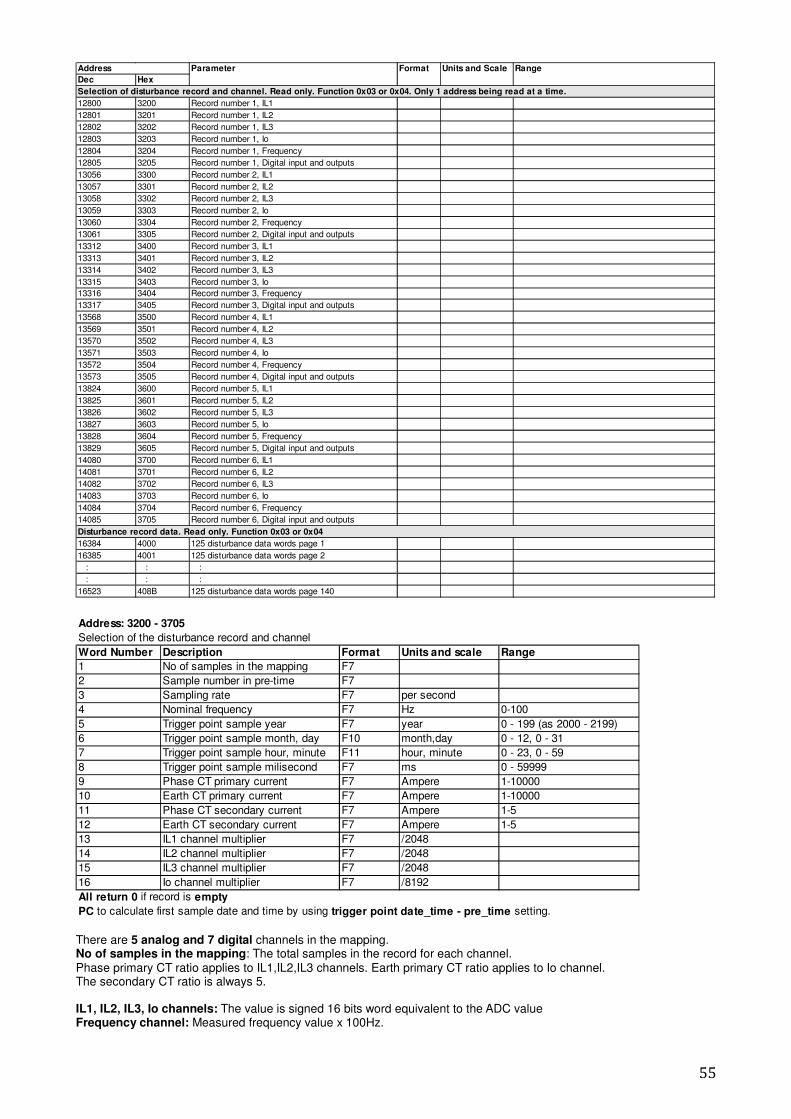
55
Dec Hex
Selection of disturbance record and channel. Read only. Function 0x03 or 0x04. Only 1 address being read at a time.
12800 3200 Record number 1, IL1
12801 3201 Record number 1, IL2
12802 3202 Record number 1, IL3
12803 3203 Record number 1, Io
12804 3204 Record number 1, Frequency
12805 3205 Record number 1, Digital input and outputs
13056 3300 Record number 2, IL1
13057 3301 Record number 2, IL2
13058 3302 Record number 2, IL3
13059 3303 Record number 2, Io
13060 3304 Record number 2, Frequency
13061 3305 Record number 2, Digital input and outputs
13312 3400 Record number 3, IL1
13313 3401 Record number 3, IL2
13314 3402 Record number 3, IL3
13315 3403 Record number 3, Io
13316 3404 Record number 3, Frequency
13317 3405 Record number 3, Digital input and outputs
13568 3500 Record number 4, IL1
13569 3501 Record number 4, IL2
13570 3502 Record number 4, IL3
13571 3503 Record number 4, Io
13572 3504 Record number 4, Frequency
13573 3505 Record number 4, Digital input and outputs
13824 3600 Record number 5, IL1
13825 3601 Record number 5, IL2
13826 3602 Record number 5, IL3
13827 3603 Record number 5, Io
13828 3604 Record number 5, Frequency
13829 3605 Record number 5, Digital input and outputs
14080 3700 Record number 6, IL1
14081 3701 Record number 6, IL2
14082 3702 Record number 6, IL3
14083 3703 Record number 6, Io
14084 3704 Record number 6, Frequency
14085 3705 Record number 6, Digital input and outputs
Disturbance record data. Read only. Function 0x03 or 0x04
16384 4000 125 disturbance data words page 1
16385 4001 125 disturbance data words page 2
: : :
: : :
16523 408B 125 disturbance data words page 140
Address Parameter Format Units and Scale Range
Address: 3200 - 3705
Selection of the disturbance record and channel
Word Number Description Format Units and scale Range
1 No of samples in the mapping F7
2 Sample number in pre-time F7
3 Sampling rate F7 per second
4 Nominal frequency F7 Hz 0-100
5 Trigger point sample year F7 year 0 - 199 (as 2000 - 2199)
6 Trigger point sample month, day F10 month,day 0 - 12, 0 - 31
7 Trigger point sample hour, minute F11 hour, minute 0 - 23, 0 - 59
8 Trigger point sample milisecond F7 ms 0 - 59999
9 Phase CT primary current F7 Ampere 1-10000
10 Earth CT primary current F7 Ampere 1-10000
11 Phase CT secondary current F7 Ampere 1-5
12 Earth CT secondary current F7 Ampere 1-5
13 IL1 channel multiplier F7 /2048
14 IL2 channel multiplier F7 /2048
15 IL3 channel multiplier F7 /2048
16 Io channel multiplier F7 /8192
All return 0 if record is empty
PC to calculate first sample date and time by using trigger point date_time - pre_time setting. There are 5 analog and 7 digital channels in the mapping. No of samples in the mapping: The total samples in the record for each channel. Phase primary CT ratio applies to IL1,IL2,IL3 channels. Earth primary CT ratio applies to Io channel. The secondary CT ratio is always 5. IL1, IL2, IL3, Io channels: The value is signed 16 bits word equivalent to the ADC value Frequency channel: Measured frequency value x 100Hz.

56
Digital input and outputs channel: 16 Bits word Bit 0: Input 1 Bit 1: Input 2 Bit 2-Bit 7: Unused Bit 8: Output Relay 1 Bit 9: Output Relay 2 Bit 10: Output Relay 3 Bit 11: Output Relay 4 Bit 12-Bit 14: Unused Bit 15: Output Relay IRF IL1, IL2, IL3 channel multiplier: This value divided by 204800 to get channel multiplier. Io channel multiplier: This value divided by 819200 to get channel multiplier. Frequency channel multiplier: 0.01
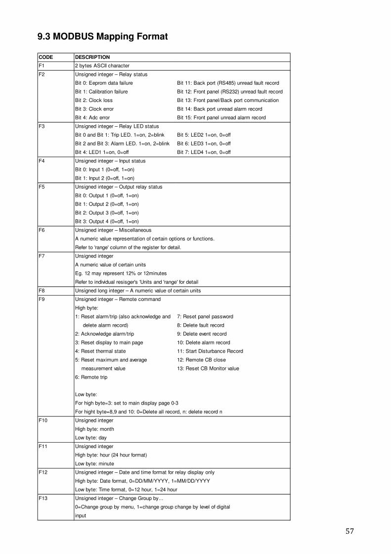
57
CODE DESCRIPTION
F1 2 bytes ASCII character
F2 Unsigned integer – Relay status
Bit 0: Eeprom data failure Bit 11: Back port (RS485) unread fault record
Bit 1: Calibration failure Bit 12: Front panel (RS232) unread fault record
Bit 2: Clock loss Bit 13: Front panel/Back port communication
Bit 3: Clock error Bit 14: Back port unread alarm record
Bit 4: Adc error Bit 15: Front panel unread alarm record
F3 Unsigned integer – Relay LED status
Bit 0 and Bit 1: Trip LED. 1=on, 2=blink Bit 5: LED2 1=on, 0=off
Bit 2 and Bit 3: Alarm LED. 1=on, 2=blink Bit 6: LED3 1=on, 0=off
Bit 4: LED1 1=on, 0=off Bit 7: LED4 1=on, 0=off
F4 Unsigned integer – Input status
Bit 0: Input 1 (0=off, 1=on)
Bit 1: Input 2 (0=off, 1=on)
F5 Unsigned integer – Output relay status
Bit 0: Output 1 (0=off, 1=on)
Bit 1: Output 2 (0=off, 1=on)
Bit 2: Output 3 (0=off, 1=on)
Bit 3: Output 4 (0=off, 1=on)
F6 Unsigned integer – Miscellaneous
A numeric value representation of certain options or functions.
Refer to 'range' column of the register for detail.
F7 Unsigned integer
A numeric value of certain units
Eg. 12 may represent 12% or 12minutes
Refer to individual resisger's 'Units and 'range' for detail
F8 Unsigned long integer – A numeric value of certain units
F9 Unsigned integer – Remote command
High byte:
1: Reset alarm/trip (also acknowledge and 7: Reset panel password
delete alarm record) 8: Delete fault record
2: Acknowledge alarm/trip 9: Delete event record
3: Reset display to main page 10: Delete alarm record
4: Reset thermal state 11: Start Disturbance Record
5: Reset maximum and average 12: Remote CB close
measurement value 13: Reset CB Monitor value
6: Remote trip
Low byte:
For high byte=3: set to main display page 0-3
For hight byte=8,9 and 10: 0=Delete all record, n: delete record n
F10 Unsigned integer
High byte: month
Low byte: day
F11 Unsigned integer
High byte: hour (24 hour format)
Low byte: minute
F12 Unsigned integer – Date and time format for relay display only
High byte: Date format, 0=DD/MM/YYYY, 1=MM/DD/YYYY
Low byte: Time format, 0=12 hour, 1=24 hour
F13 Unsigned integer – Change Group by...
0=Change group by menu, 1=change group change by level of digital
input
9.3 MODBUS Mapping Format
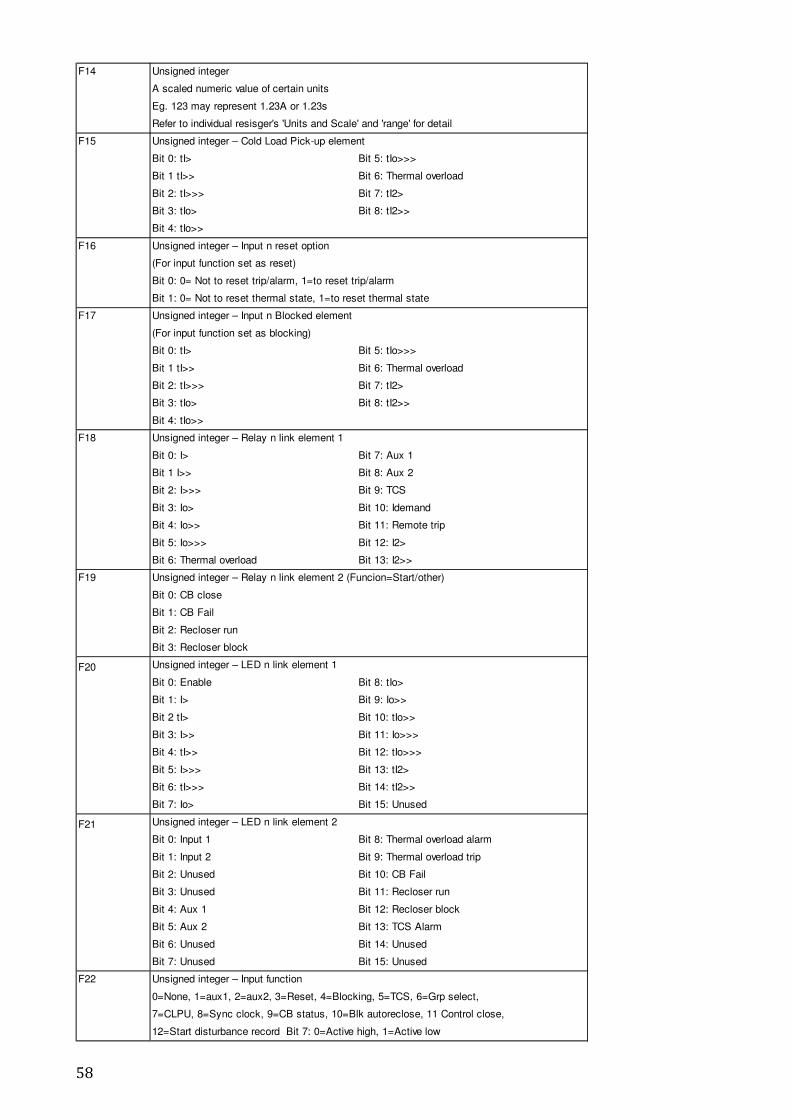
58
F14 Unsigned integer
A scaled numeric value of certain units
Eg. 123 may represent 1.23A or 1.23s
Refer to individual resisger's 'Units and Scale' and 'range' for detail
F15 Unsigned integer – Cold Load Pick-up element
Bit 0: tI> Bit 5: tIo>>>
Bit 1 tI>> Bit 6: Thermal overload
Bit 2: tI>>> Bit 7: tI2>
Bit 3: tIo> Bit 8: tI2>>
Bit 4: tIo>>
F16 Unsigned integer – Input n reset option
(For input function set as reset)
Bit 0: 0= Not to reset trip/alarm, 1=to reset trip/alarm
Bit 1: 0= Not to reset thermal state, 1=to reset thermal state
F17 Unsigned integer – Input n Blocked element
(For input function set as blocking)
Bit 0: tI> Bit 5: tIo>>>
Bit 1 tI>> Bit 6: Thermal overload
Bit 2: tI>>> Bit 7: tI2>
Bit 3: tIo> Bit 8: tI2>>
Bit 4: tIo>>
F18 Unsigned integer – Relay n link element 1
Bit 0: I> Bit 7: Aux 1
Bit 1 I>> Bit 8: Aux 2
Bit 2: I>>> Bit 9: TCS
Bit 3: Io> Bit 10: Idemand
Bit 4: Io>> Bit 11: Remote trip
Bit 5: Io>>> Bit 12: I2>
Bit 6: Thermal overload Bit 13: I2>>
F19 Unsigned integer – Relay n link element 2 (Funcion=Start/other)
Bit 0: CB close
Bit 1: CB Fail
Bit 2: Recloser run
Bit 3: Recloser block
F20 Unsigned integer – LED n link element 1
Bit 0: Enable Bit 8: tIo>
Bit 1: I> Bit 9: Io>>
Bit 2 tI> Bit 10: tIo>>
Bit 3: I>> Bit 11: Io>>>
Bit 4: tI>> Bit 12: tIo>>>
Bit 5: I>>> Bit 13: tI2>
Bit 6: tI>>> Bit 14: tI2>>
Bit 7: Io> Bit 15: Unused
F21 Unsigned integer – LED n link element 2
Bit 0: Input 1 Bit 8: Thermal overload alarm
Bit 1: Input 2 Bit 9: Thermal overload trip
Bit 2: Unused Bit 10: CB Fail
Bit 3: Unused Bit 11: Recloser run
Bit 4: Aux 1 Bit 12: Recloser block
Bit 5: Aux 2 Bit 13: TCS Alarm
Bit 6: Unused Bit 14: Unused
Bit 7: Unused Bit 15: Unused
F22 Unsigned integer – Input function
0=None, 1=aux1, 2=aux2, 3=Reset, 4=Blocking, 5=TCS, 6=Grp select,
7=CLPU, 8=Sync clock, 9=CB status, 10=Blk autoreclose, 11 Control close,
12=Start disturbance record Bit 7: 0=Active high, 1=Active low
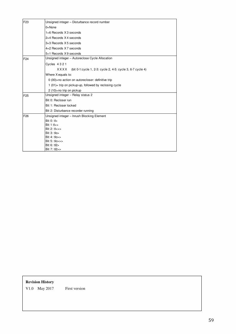
59
F23 Unsigned integer – Disturbance record number
0=None
1=6 Records X 3 seconds
2=4 Records X 4 seconds
3=3 Records X 5 seconds
4=2 Records X 7 seconds
5=1 Records X 9 seconds
F24 Unsigned integer – Autoreclose Cycle Allocation
Cycles 4 3 2 1
X X X X (bit 0-1:cycle 1, 2-3: cycle 2, 4-5: cycle 3, 6-7 cycle 4)
Where X equals to:
0 (00)=no action on autorecloser: definitive trip
1 (01)= trip on pickup-up, followed by reclosing cycle
2 (10)=no trip on pickup
F25 Unsigned integer – Relay status 2
Bit 0: Recloser run
Bit 1: Recloser locked
Bit 2: Disturbance recorder running
F26 Unsigned integer – Inrush Blocking Element
Bit 0: tI>
Bit 1 tI>>
Bit 2: tI>>>
Bit 3: tIo>
Bit 4: tIo>>
Bit 5: tIo>>>
Bit 6: tI2>
Bit 7: tI2>>
Revision History
V1.0 May 2017 First version