Embed Size (px)
Citation preview
USER MANUAL
MODEL:
FC-404NET 4X4 Dante Interface
P/N: 2900-300477 Rev 2 www.kramerAV.com
FC-404NET – Contents i
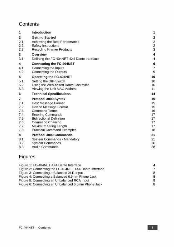
Contents
1 Introduction 1 2 Getting Started 2 2.1 Achieving the Best Performance 2 2.2 Safety Instructions 2 2.3 Recycling Kramer Products 3 3 Overview 4 3.1 Defining the FC-404NET 4X4 Dante Interface 4 4 Connecting the FC-404NET 6 4.1 Connecting the Inputs 7 4.2 Connecting the Outputs 9 5 Operating the FC-404NET 10 5.1 Setting the DIP-Switch 10 5.2 Using the Web-based Dante Controller 10 5.3 Viewing the Unit MAC Address 11 6 Technical Specifications 14 7 Protocol 3000 Syntax 15 7.1 Host Message Format 15 7.2 Device Message Format 15 7.3 Command Terms 16 7.4 Entering Commands 17 7.5 Bidirectional Definition 17 7.6 Command Chaining 17 7.7 Maximum String Length 17 7.8 Practical Command Examples 18 8 Protocol 3000 Commands 21 8.1 System Commands - Mandatory 21 8.2 System Commands 26 8.3 Audio Commands 28
Figures
Figure 1: FC-404NET 4X4 Dante Interface 4 Figure 2: Connecting the FC-404NET 4X4 Dante Interface 7 Figure 3: Connecting a Balanced XLR Input 8 Figure 4: Connecting a Balanced 6.5mm Phone Jack 8 Figure 5: Connecting an Unbalanced RCA Input 8 Figure 6: Connecting an Unbalanced 6.5mm Phone Jack 8

FC-404NET – Introduction 1
1 Introduction
Welcome to Kramer Electronics! Since 1981, Kramer Electronics has been
providing a world of unique, creative, and affordable solutions to the vast range
of problems that confront video, audio, presentation, and broadcasting
professionals on a daily basis. In recent years, we have redesigned and
upgraded most of our line, making the best even better!
Our 1,000-plus different models now appear in 14 groups that are clearly defined
by function: GROUP 1: Distribution Amplifiers; GROUP 2: Switchers and
Routers; GROUP 3: Control Systems; GROUP 4: Format/Standards Converters;
GROUP 5: Range Extenders and Repeaters; GROUP 6: Specialty AV Products;
GROUP 7: Scan Converters and Scalers; GROUP 8: Cables and Connectors;
GROUP 9: Room Connectivity; GROUP 10: Accessories and Rack Adapters;
GROUP 11: Sierra Video Products; GROUP 12: Digital Signage; GROUP 13:
Audio; and GROUP 14: Collaboration.
Congratulations on purchasing your Kramer FC-404NET 4X4 Dante Interface,
which is ideal for the following typical applications:
Boardrooms
Education
Hospitality
Airline and rail transportation
Retail
Entertainment
Houses of worship
2 FC-404NET - Getting Started
2 Getting Started
We recommend that you:
Unpack the equipment carefully and save the original box and packaging
materials for possible future shipment
Review the contents of this user manual
Go to www.kramerav.com/downloads/FC-404NET to check for up-to-date
user manuals, application programs, and to check if firmware upgrades are
available (where appropriate).
2.1 Achieving the Best Performance
To achieve the best performance:
Use only good quality connection cables (we recommend Kramer high-
performance, high-resolution cables) to avoid interference, deterioration in
signal quality due to poor matching, and elevated noise levels (often
associated with low quality cables)
Do not secure the cables in tight bundles or roll the slack into tight coils
Avoid interference from neighbouring electrical appliances that may
adversely influence signal quality
Position your FC-404NET away from moisture, excessive sunlight and dust
This equipment is to be used only inside a building. It may only be
connected to other equipment that is installed inside a building.
2.2 Safety Instructions
Caution: There are no operator serviceable parts inside the unit
Warning: Use only the Kramer Electronics power supply that is
provided with the unit
Warning: Disconnect the power and unplug the unit from the wall
before installing
FC-404NET – Getting Started 3
2.3 Recycling Kramer Products
The Waste Electrical and Electronic Equipment (WEEE) Directive 2002/96/EC
aims to reduce the amount of WEEE sent for disposal to landfill or incineration
by requiring it to be collected and recycled. To comply with the WEEE Directive,
Kramer Electronics has made arrangements with the European Advanced
Recycling Network (EARN) and will cover any costs of treatment, recycling and
recovery of waste Kramer Electronics branded equipment on arrival at the EARN
facility. For details of Kramer’s recycling arrangements in your particular country
go to our recycling pages at
http://www.kramerelectronics.com/support/recycling/.
4 FC-404NET - Overview
3 Overview
The Kramer FC-404NET is a four−input/four−output Dante™ interface with line
or microphone level inputs and line level outputs. It connects analog inputs to a
digital Dante network or outputs four channels from a Dante network.
The FC-404NET 4X4 Dante Interface features:
A Dante network interface
Four balanced, line-level/mic inputs
Four balanced, line-level outputs from the network
Independent input gain/output volume settings per channel
DIP-switch controlled input settings – line level ( 0db) or mic level
(+20dB) with phantom +48 volts
Control via the Dante IP control matrix or Kramer Protocol 3000 via
RS-232 connection
Compact MegaTOOLS® housing where 2 units can be rack mounted
side-by-side in a 1U rack space with the optional RK-T2B rack adapter.
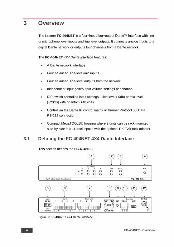
3.1 Defining the FC-404NET 4X4 Dante Interface
This section defines the FC-404NET.
Figure 1: FC-404NET 4X4 Dante Interface
FC-404NET – Overview 5
# Feature Function
1 CLIPPING 1-4, IN-OUT LEDs Lights when in/out signal is clipped
2 SYS LEDs Lights green when Dante network available or red if error
3 SYNC LEDs Lights green for digital audio normal or red if error
4 ON LED Lights green when the unit is powered on
5 MIC PHANTOM/+48V ON 1-4 DIP-Switches
Set up (OFF) for line level input, set down (ON) for mic level input and +48v phantom supply to the microphones
6 INPUTS 5-pin Terminal Blocks (1-4)
Connect to balanced line-level audio sources 1-4, (+, –, G) (line or mic levels)
7 OUTPUTS 5-pin Terminal Blocks (1-4)
Connect to balanced line-level audio acceptors 1-4, (+, –, G)
8 DANTE NET RJ-45 Connector Connects to the IP network
9 DEF Button To reset/reboot the device, press and release the button
To reset to factory settings, press and hold the button for 30 secs
10 CONTROL RS-232 3-pin Terminal Block
Connects to a control unit or PC running Protocol 3000
11 CONTROL USB Connector N/A
12 5V DC Power Connector Connects to the power supply

6 FC-404NET - Connecting the FC-404NET
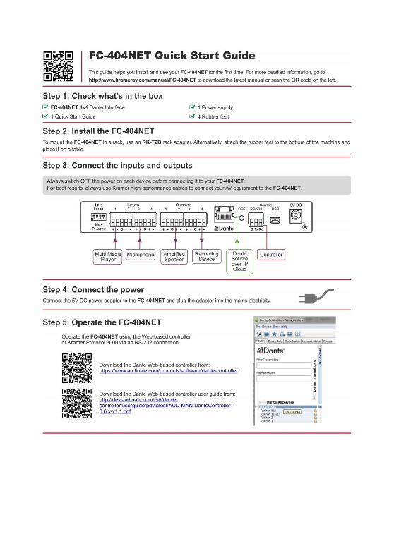
4 Connecting the FC-404NET
Always switch off the power to each device before connecting it to
your FC-404NET. After connecting your FC-404NET, connect its
power and then switch on the power to each device.
You do not have to connect all the inputs and outputs, connect only
those that are required.
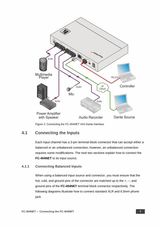
To connect the FC-404NET, as illustrated in the example in Figure 2, do the
following:
1. Connect up to four balanced audio sources, (for example, multimedia
player, microphone) to the 3-pin Input terminal blocks 1-4.
2. Set the MIC Phantom DIP-switches according to the input type: up (OFF)
for line level inputs or down (ON) for microphone inputs.
3. Connect the Output 3-pin terminal block to up to four balanced audio
acceptors, (for example, an amplifier with speaker, a recording device).
4. Connect the Dante RJ-45 connector to the any available IP network.
5. If needed, connect a PC or controller to the FC-404NET via the RS-232
connection (PC only).
6. Connect the power adapter to the FC-404NET and plug the power
adapter into the mains power supply.
FC-404NET – Connecting the FC-404NET 7
Figure 2: Connecting the FC-404NET 4X4 Dante Interface
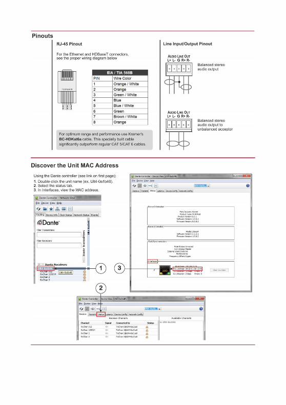
4.1 Connecting the Inputs
Each input channel has a 3-pin terminal block connector that can accept either a
balanced or an unbalanced connection; however, an unbalanced connection
requires some modifications. The next two sections explain how to connect the
FC-404NET to its input source.
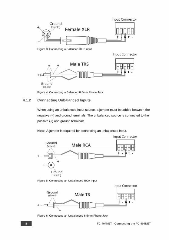
4.1.1 Connecting Balanced Inputs
When using a balanced input source and connector, you must ensure that the
hot, cold, and ground pins of the connector are matched up to the +, –, and
ground pins of the FC-404NET terminal block connector respectively. The
following diagrams illustrate how to connect standard XLR and 6.5mm phone
jack.
8 FC-404NET - Connecting the FC-404NET
Figure 3: Connecting a Balanced XLR Input
Figure 4: Connecting a Balanced 6.5mm Phone Jack
4.1.2 Connecting Unbalanced Inputs
When using an unbalanced input source, a jumper must be added between the
negative (–) and ground terminals. The unbalanced source is connected to the
positive (+) and ground terminals.
Note: A jumper is required for connecting an unbalanced input.
Figure 5: Connecting an Unbalanced RCA Input
Figure 6: Connecting an Unbalanced 6.5mm Phone Jack
FC-404NET – Connecting the FC-404NET 9
4.2 Connecting the Outputs
Your FC-404NET is provided with a 3-pin terminal block for each output channel.
This connector offers a balanced output to interface with the input of another
device.
Connection methods for balanced and unbalanced outputs are identical as the
methods for inputs as referenced in Section 4.1.
For any microphone that needs +48 volts of power, set the DIP-switch for that
channel ON (down).
10 FC-404NET - Operating the FC-404NET
5 Operating the FC-404NET
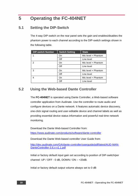
5.1 Setting the DIP-Switch
The 4-way DIP-switch on the rear panel sets the gain and enables/disables the
phantom power to each channel according to the DIP-switch settings shown in
the following table.
DIP-switch Number Switch Setting State
1 On Mic level + Phantom
Off Line level
2 On Mic level + Phantom
Off Line level
3 On Mic level + Phantom
Off Line level
4 On Mic level + Phantom
Off Line level
5.2 Using the Web-based Dante Controller
The FC-404NET is operated using Dante Controller, a Web-based software
controller application from Audinate. Use the controller to route audio and
configure devices on a Dante network. It features automatic device discovery,
one-click signal routing and user-editable device and channel labels as well as
providing essential device status information and powerful real-time network
monitoring.
Download the Dante Web-based Controller from:
https://www.audinate.com/products/software/dante-controller
Download the Dante Web-based controller User Guide from:
http://dev.audinate.com/GA/dante-controller/userguide/pdf/latest/AUD-MAN-DanteController-3.6.x-v1.1.pdf
Initial or factory default input gain set according to position of DIP-switch/per
channel: UP / OFF - 0 dB, DOWN / ON – +20dB.
Initial or factory default output volume always set to 0 dB
FC-404NET – Operating the FC-404NET 11
These values can be changed in any time through RS-232 interface by Kramer
3000 protocol commands. Input gain can be set in range -12 dB to +60 dB and
output volume can be set in range +9 dB to -80 dB or Mute.
Recycling the power doesn’t change the last current values of input gain and
output volume.
To execute factory default setup press and hold pushbutton DEF for about 30
sec.
The working status of the LEDs are as follows:
SYS: System ON – green, system OFF - red
SYNC: unit is Master Green is flashing –, lights on – unit is Slave, Red lights
OFF
Clipping – all 8 LEDs must be light OFF
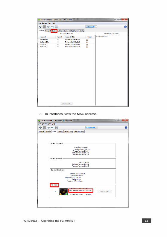
5.3 Viewing the Unit MAC Address
The MAC address of the unit is supplied by the Dante network. To view the MAC
address, perform the following:

12 FC-404NET - Operating the FC-404NET
1. In the Dante controller, double-click the unit name (in this example, Ult4-
0a1b46).
2. Select the Status tab.
FC-404NET – Operating the FC-404NET 13
3. In Interfaces, view the MAC address.
14 FC-404NET - Technical Specifications
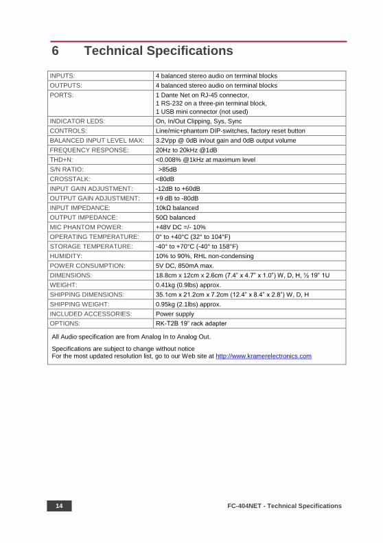
6 Technical Specifications
INPUTS: 4 balanced stereo audio on terminal blocks
OUTPUTS: 4 balanced stereo audio on terminal blocks
PORTS: 1 Dante Net on RJ-45 connector,
1 RS-232 on a three-pin terminal block,
1 USB mini connector (not used)
INDICATOR LEDS: On, In/Out Clipping, Sys, Sync
CONTROLS: Line/mic+phantom DIP-switches, factory reset button
BALANCED INPUT LEVEL MAX: 3.2Vpp @ 0dB in/out gain and 0dB output volume
FREQUENCY RESPONSE: 20Hz to 20kHz @1dB
THD+N: <0.008% @1kHz at maximum level
S/N RATIO: >85dB
CROSSTALK: <80dB
INPUT GAIN ADJUSTMENT: -12dB to +60dB
OUTPUT GAIN ADJUSTMENT: +9 dB to -80dB
INPUT IMPEDANCE: 10kΩ balanced
OUTPUT IMPEDANCE: 50Ω balanced
MIC PHANTOM POWER: +48V DC =/- 10%
OPERATING TEMPERATURE: 0° to +40°C (32° to 104°F)
STORAGE TEMPERATURE: -40° to +70°C (-40° to 158°F)
HUMIDITY: 10% to 90%, RHL non-condensing
POWER CONSUMPTION: 5V DC, 850mA max.
DIMENSIONS: 18.8cm x 12cm x 2.6cm (7.4” x 4.7” x 1.0”) W, D, H, ½ 19” 1U
WEIGHT: 0.41kg (0.9lbs) approx.
SHIPPING DIMENSIONS: 35.1cm x 21.2cm x 7.2cm (12.4” x 8.4” x 2.8”) W, D, H
SHIPPING WEIGHT: 0.95kg (2.1lbs) approx.
INCLUDED ACCESSORIES: Power supply
OPTIONS: RK-T2B 19” rack adapter
All Audio specification are from Analog In to Analog Out.
Specifications are subject to change without notice For the most updated resolution list, go to our Web site at http://www.kramerelectronics.com
FC-404NET – Protocol 3000 Syntax 15
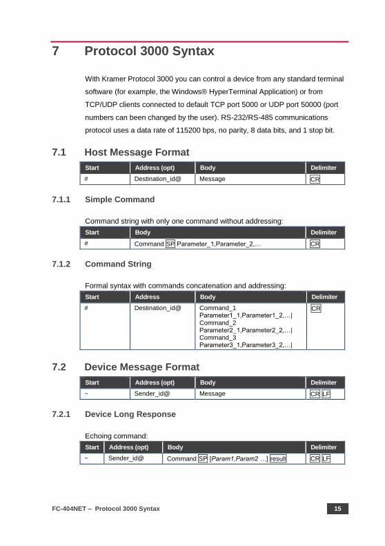
7 Protocol 3000 Syntax
With Kramer Protocol 3000 you can control a device from any standard terminal
software (for example, the Windows® HyperTerminal Application) or from
TCP/UDP clients connected to default TCP port 5000 or UDP port 50000 (port
numbers can been changed by the user). RS-232/RS-485 communications
protocol uses a data rate of 115200 bps, no parity, 8 data bits, and 1 stop bit.
7.1 Host Message Format
Start Address (opt) Body Delimiter
# Destination_id@ Message CR
7.1.1 Simple Command
Command string with only one command without addressing:
Start Body Delimiter
# Command SP Parameter_1,Parameter_2,… CR
7.1.2 Command String
Formal syntax with commands concatenation and addressing:
Start Address Body Delimiter
# Destination_id@ Command_1 Parameter1_1,Parameter1_2,…| Command_2 Parameter2_1,Parameter2_2,…| Command_3 Parameter3_1,Parameter3_2,…|
CR
7.2 Device Message Format
Start Address (opt) Body Delimiter
~ Sender_id@ Message CR LF
7.2.1 Device Long Response
Echoing command:
Start Address (opt) Body Delimiter
~ Sender_id@ Command SP [Param1,Param2 …] result CR LF
16 FC-404NET - Protocol 3000 Syntax
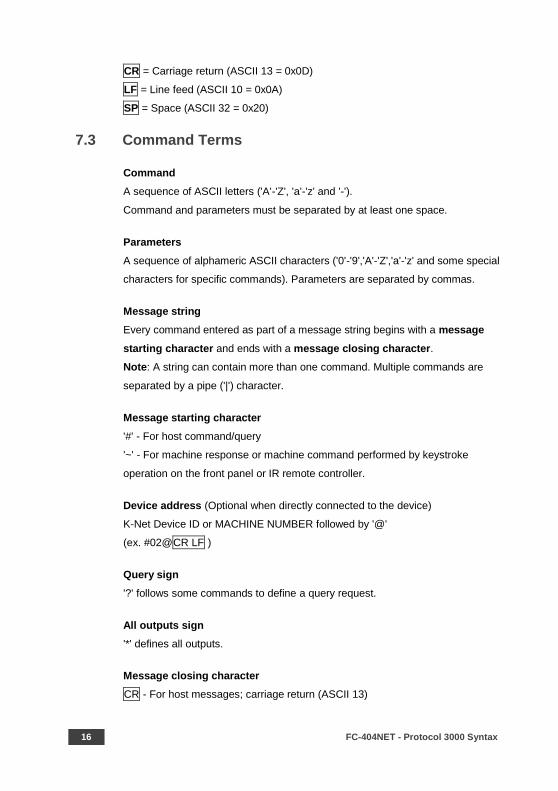
CR = Carriage return (ASCII 13 = 0x0D)
LF = Line feed (ASCII 10 = 0x0A)
SP = Space (ASCII 32 = 0x20)
7.3 Command Terms
Command
A sequence of ASCII letters ('A'-'Z', 'a'-'z' and '-').
Command and parameters must be separated by at least one space.
Parameters
A sequence of alphameric ASCII characters ('0'-'9','A'-'Z','a'-'z' and some special
characters for specific commands). Parameters are separated by commas.
Message string
Every command entered as part of a message string begins with a message
starting character and ends with a message closing character.
Note: A string can contain more than one command. Multiple commands are
separated by a pipe ('|') character.
Message starting character
'#' - For host command/query
'~' - For machine response or machine command performed by keystroke
operation on the front panel or IR remote controller.
Device address (Optional when directly connected to the device)
K-Net Device ID or MACHINE NUMBER followed by '@'
(ex. #02@CR LF )
Query sign
'?' follows some commands to define a query request.
All outputs sign
'*' defines all outputs.
Message closing character
CR - For host messages; carriage return (ASCII 13)
FC-404NET – Protocol 3000 Syntax 17
CR LF - For machine messages; carriage return (ASCII 13) + line-feed (ASCII
10)
Command chain separator character
When a message string contains more than one command, a pipe ('|') character
separates each command.
Spaces between parameters or command terms are ignored.
7.4 Entering Commands
You can directly enter all commands using a terminal with ASCII communication
software, such as HyperTerminal, Hercules, etc. Connect the terminal to the
serial or Ethernet port on the Kramer device. To enter CR, press the Enter key.
(LF is also sent but is ignored by the command parser).
For commands sent from some non-Kramer controllers such as Crestron, some
characters require special coding (such as, /X##). Refer to the controller manual.
7.5 Bidirectional Definition
All commands are bidirectional. That is, if the device receives the code, it
performs the instruction. If the instruction is performed (due to a keystroke
operation on the front panel or IR controller) these codes are sent to the PC or
other RS-232 / Ethernet controller.
7.6 Command Chaining
Multiple commands can be chained in the same string. Each command is
delimited by a pipe character ('|'). When chaining commands, enter the
message starting character and the message closing character once only, at
the beginning of the string and at the end.
Commands in the string do not execute until the closing character is entered. A
separate response is sent for every command in the chain.
7.7 Maximum String Length
64 characters (except for special commands that are defined in the command
syntax description).
18 FC-404NET - Protocol 3000 Syntax
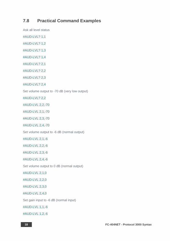
7.8 Practical Command Examples
Ask all level status
#AUD-LVL? 1,1
#AUD-LVL? 1,2
#AUD-LVL? 1,3
#AUD-LVL? 1,4
#AUD-LVL? 2,1
#AUD-LVL? 2,2
#AUD-LVL? 2,3
#AUD-LVL? 2,4
Set volume output to -70 dB (very low output)
#AUD-LVL? 2,2
#AUD-LVL 2,2,-70
#AUD-LVL 2,1,-70
#AUD-LVL 2,3,-70
#AUD-LVL 2,4,-70
Set volume output to -6 dB (normal output)
#AUD-LVL 2,1,-6
#AUD-LVL 2,2,-6
#AUD-LVL 2,3,-6
#AUD-LVL 2,4,-6
Set volume output to 0 dB (normal output)
#AUD-LVL 2,1,0
#AUD-LVL 2,2,0
#AUD-LVL 2,3,0
#AUD-LVL 2,4,0
Set gain input to -6 dB (normal input)
#AUD-LVL 1,1,-6
#AUD-LVL 1,2,-6
FC-404NET – Protocol 3000 Syntax 19
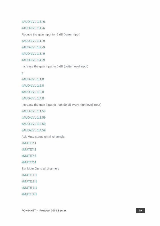
#AUD-LVL 1,3,-6
#AUD-LVL 1,4,-6
Reduce the gain input to -9 dB (lower input)
#AUD-LVL 1,1,-9
#AUD-LVL 1,2,-9
#AUD-LVL 1,3,-9
#AUD-LVL 1,4,-9
Increase the gain input to 0 dB (better level input)
#
#AUD-LVL 1,1,0
#AUD-LVL 1,2,0
#AUD-LVL 1,3,0
#AUD-LVL 1,4,0
Increase the gain input to max 59 dB (very high level input)
#AUD-LVL 1,1,59
#AUD-LVL 1,2,59
#AUD-LVL 1,3,59
#AUD-LVL 1,4,59
Ask Mute status on all channels
#MUTE? 1
#MUTE? 2
#MUTE? 3
#MUTE? 4
Set Mute On to all channels
#MUTE 1,1
#MUTE 2,1
#MUTE 3,1
#MUTE 4,1
20 FC-404NET - Protocol 3000 Syntax
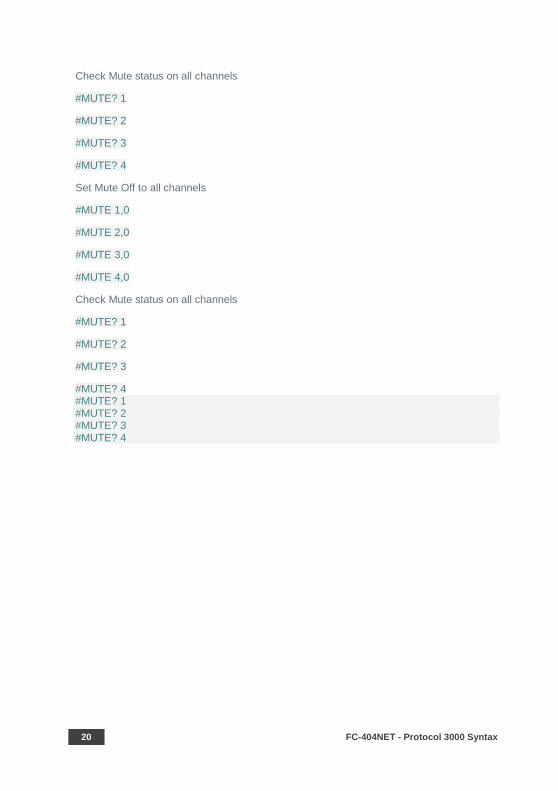
Check Mute status on all channels
#MUTE? 1
#MUTE? 2
#MUTE? 3
#MUTE? 4
Set Mute Off to all channels
#MUTE 1,0
#MUTE 2,0
#MUTE 3,0
#MUTE 4,0
Check Mute status on all channels
#MUTE? 1
#MUTE? 2
#MUTE? 3
#MUTE? 4 #MUTE? 1 #MUTE? 2 #MUTE? 3 #MUTE? 4
FC-404NET – Protocol 3000 Commands 21
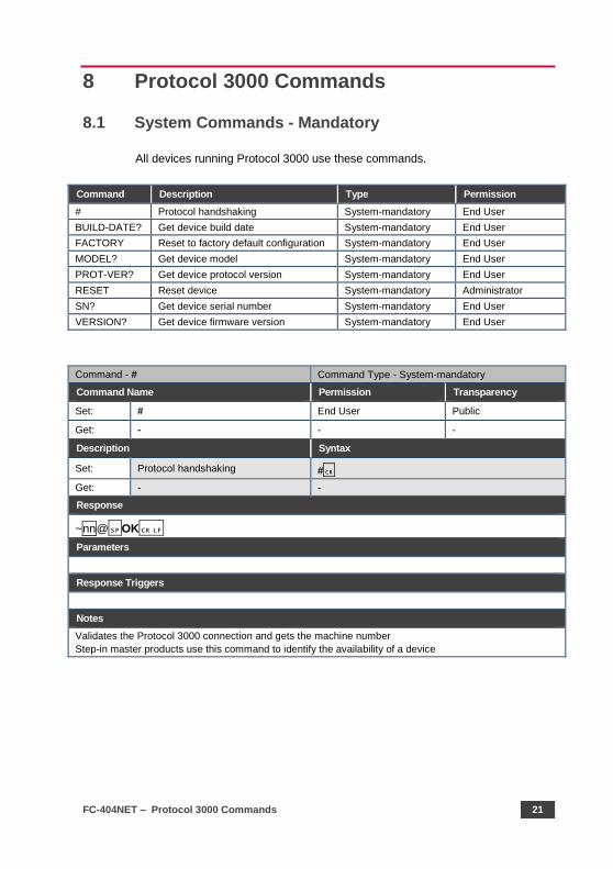
8 Protocol 3000 Commands
8.1 System Commands - Mandatory
All devices running Protocol 3000 use these commands.
Command Description Type Permission
# Protocol handshaking System-mandatory End User
BUILD-DATE? Get device build date System-mandatory End User
FACTORY Reset to factory default configuration System-mandatory End User
MODEL? Get device model System-mandatory End User
PROT-VER? Get device protocol version System-mandatory End User
RESET Reset device System-mandatory Administrator
SN? Get device serial number System-mandatory End User
VERSION? Get device firmware version System-mandatory End User
Command - # Command Type - System-mandatory
Command Name Permission Transparency
Set: # End User Public
Get: - - -
Description Syntax
Set: Protocol handshaking #
Get: - -
Response
~nn@OK
Parameters
Response Triggers
Notes
Validates the Protocol 3000 connection and gets the machine number
Step-in master products use this command to identify the availability of a device
22 FC-404NET - Protocol 3000 Commands
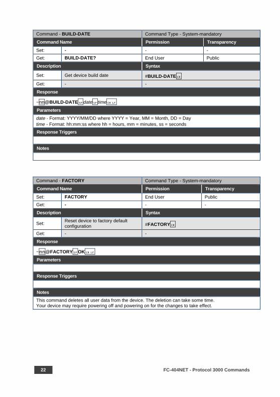
Command - BUILD-DATE Command Type - System-mandatory
Command Name Permission Transparency
Set: - - -
Get: BUILD-DATE? End User Public
Description Syntax
Set: Get device build date #BUILD-DATE
Get: - -
Response
~nn@BUILD-DATEdatetime
Parameters
date - Format: YYYY/MM/DD where YYYY = Year, MM = Month, DD = Day
time - Format: hh:mm:ss where hh = hours, mm = minutes, ss = seconds
Response Triggers
Notes
Command - FACTORY Command Type - System-mandatory
Command Name Permission Transparency
Set: FACTORY End User Public
Get: - - -
Description Syntax
Set: Reset device to factory default configuration #FACTORY
Get: - -
Response
~nn@FACTORYOK
Parameters
Response Triggers
Notes
This command deletes all user data from the device. The deletion can take some time. Your device may require powering off and powering on for the changes to take effect.
FC-404NET – Protocol 3000 Commands 23
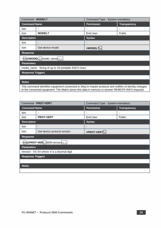
Command - MODEL? Command Type - System-mandatory
Command Name Permission Transparency
Set: - - -
Get: MODEL? End User Public
Description Syntax
Set: - -
Get: Get device model #MODEL?
Response
~nn@MODELmodel_name
Parameters
model_name - String of up to 19 printable ASCII chars
Response Triggers
Notes
This command identifies equipment connected to Step-in master products and notifies of identity changes to the connected equipment. The Matrix saves this data in memory to answer REMOTE-INFO requests
Command - PROT-VER? Command Type - System-mandatory
Command Name Permission Transparency
Set: - - -
Get: PROT-VER? End User Public
Description Syntax
Set: - -
Get: Get device protocol version #PROT-VER?
Response
~nn@PROT-VER3000:version
Parameters
Version - XX.XX where X is a decimal digit
Response Triggers
Notes
24 FC-404NET - Protocol 3000 Commands
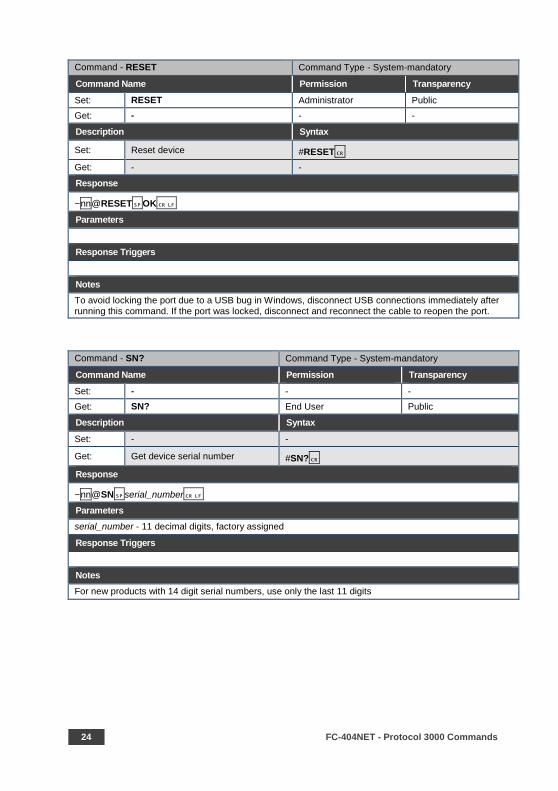
Command - RESET Command Type - System-mandatory
Command Name Permission Transparency
Set: RESET Administrator Public
Get: - - -
Description Syntax
Set: Reset device #RESET
Get: - -
Response
~nn@RESETOK
Parameters
Response Triggers
Notes
To avoid locking the port due to a USB bug in Windows, disconnect USB connections immediately after running this command. If the port was locked, disconnect and reconnect the cable to reopen the port.
Command - SN? Command Type - System-mandatory
Command Name Permission Transparency
Set: - - -
Get: SN? End User Public
Description Syntax
Set: - -
Get: Get device serial number #SN?
Response
~nn@SNserial_number
Parameters
serial_number - 11 decimal digits, factory assigned
Response Triggers
Notes
For new products with 14 digit serial numbers, use only the last 11 digits
FC-404NET – Protocol 3000 Commands 25
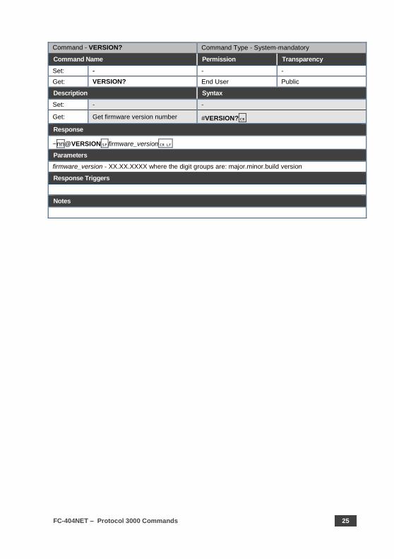
Command - VERSION? Command Type - System-mandatory
Command Name Permission Transparency
Set: - - -
Get: VERSION? End User Public
Description Syntax
Set: - -
Get: Get firmware version number #VERSION?
Response
~nn@VERSIONfirmware_version
Parameters
firmware_version - XX.XX.XXXX where the digit groups are: major.minor.build version
Response Triggers
Notes
26 FC-404NET - Protocol 3000 Commands
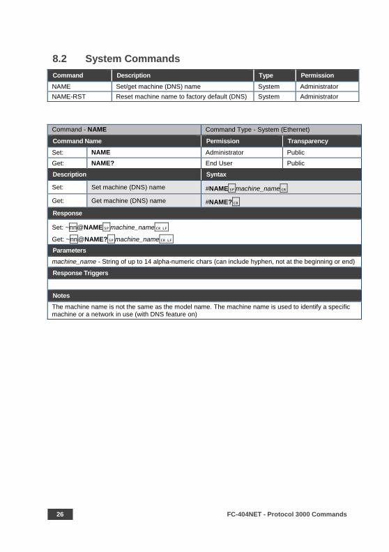
8.2 System Commands
Command Description Type Permission
NAME Set/get machine (DNS) name System Administrator
NAME-RST Reset machine name to factory default (DNS) System Administrator
Command - NAME Command Type - System (Ethernet)
Command Name Permission Transparency
Set: NAME Administrator Public
Get: NAME? End User Public
Description Syntax
Set: Set machine (DNS) name #NAMEmachine_name
Get: Get machine (DNS) name #NAME?
Response
Set: ~nn@NAMEmachine_name
Get: ~nn@NAME?machine_name
Parameters
machine_name - String of up to 14 alpha-numeric chars (can include hyphen, not at the beginning or end)
Response Triggers
Notes
The machine name is not the same as the model name. The machine name is used to identify a specific machine or a network in use (with DNS feature on)
FC-404NET – Protocol 3000 Commands 27
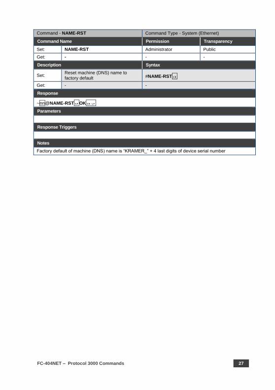
Command - NAME-RST Command Type - System (Ethernet)
Command Name Permission Transparency
Set: NAME-RST Administrator Public
Get: - - -
Description Syntax
Set: Reset machine (DNS) name to factory default #NAME-RST
Get: - -
Response
~nn@NAME-RSTOK
Parameters
Response Triggers
Notes
Factory default of machine (DNS) name is “KRAMER_” + 4 last digits of device serial number
28 FC-404NET - Protocol 3000 Commands
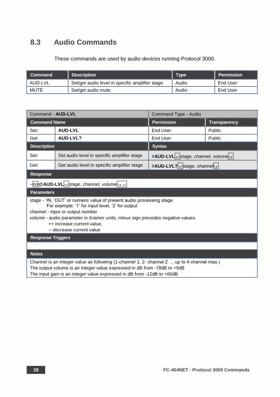
8.3 Audio Commands
These commands are used by audio devices running Protocol 3000.
Command Description Type Permission
AUD-LVL Set/get audio level in specific amplifier stage Audio End User
MUTE Set/get audio mute Audio End User
Command - AUD-LVL Command Type - Audio
Command Name Permission Transparency
Set: AUD-LVL End User Public
Get: AUD-LVL? End User Public
Description Syntax
Set: Set audio level in specific amplifier stage #AUD-LVLstage, channel, volume
Get: Get audio level in specific amplifier stage #AUD-LVL?stage, channel
Response
~nn@AUD-LVLstage, channel, volume
Parameters
stage - ‘IN, ’OUT’ or numeric value of present audio processing stage For example: ‘1’ for input level, ‘2’ for output
channel - input or output number
volume - audio parameter in Kramer units, minus sign precedes negative values.
++ increase current value,
-- decrease current value
Response Triggers
Notes
Channel is an integer value as following (1-channel 1, 2- channel 2 … up to 4 channel max.)
The output volume is an integer value expressed in dB from -78dB to +9dB
The input gain is an integer value expressed in dB from -12dB to +60dB
FC-404NET – Protocol 3000 Commands 29
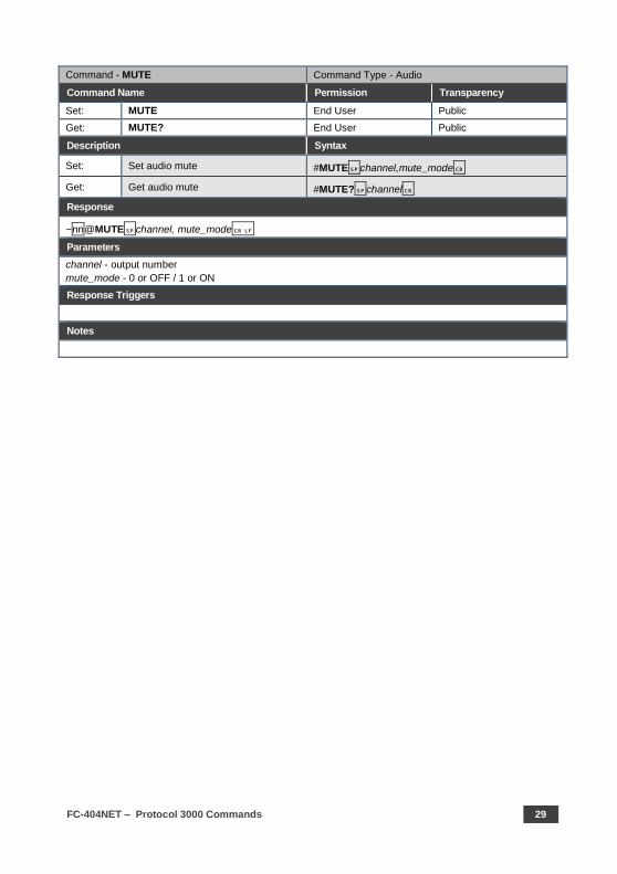
Command - MUTE Command Type - Audio
Command Name Permission Transparency
Set: MUTE End User Public
Get: MUTE? End User Public
Description Syntax
Set: Set audio mute #MUTEchannel,mute_mode
Get: Get audio mute #MUTE?channel
Response
~nn@MUTEchannel, mute_mode
Parameters
channel - output number
mute_mode - 0 or OFF / 1 or ON
Response Triggers
Notes

1
SAFETY WARNING
Disconnect the unit from the power supply before opening and servicing
For the latest information on our products and a list of Kramer distributors,
visit our Web site to find updates to this user manual.
We welcome your questions, comments, and feedback.
www.kramerAV.com [email protected]
P/N: 2900- 300477 Rev: 2