Embed Size (px)
Citation preview
User Manual – June 2013
visit our website: www.hydraforce.com download a copy of i-Design: info.hydraforce.com/downloadi-Design
questions about i-Design, contact: [email protected] need help designing a custom manifold: info.hydraforce.com/Free-Custom-Circuit-Consultation/

HydraForce i-Design User's Manual
ii
FAMIC Technologies Inc.
All rights reserved.
User’s Guide for the HydraForce i-Design. (Revision 204)
REPRODUCTION
Reproduction of this manual or software, in whole or in part, is strictly prohibited without the
express written consent of HydraForce Inc.
It is allowed to print this document from the electronic format
WINDOWS is a registered trademark of Microsoft Corp.
AUTOMATION STUDIO is a registered trademark of FAMIC Technologies Inc.
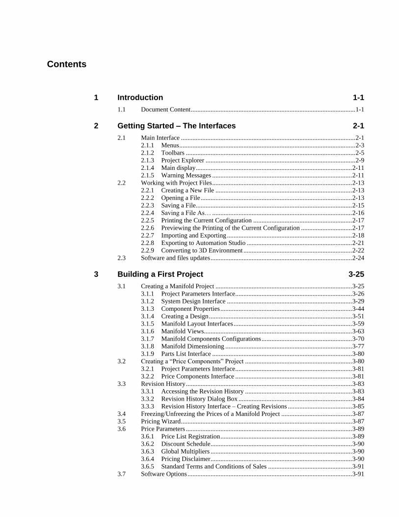
Contents
1 Introduction 1-1
1.1 Document Content .................................................................................................... 1-1
2 Getting Started – The Interfaces 2-1
2.1 Main Interface .......................................................................................................... 2-1 2.1.1 Menus ........................................................................................................... 2-3 2.1.2 Toolbars ....................................................................................................... 2-5 2.1.3 Project Explorer ........................................................................................... 2-9 2.1.4 Main display ............................................................................................... 2-11 2.1.5 Warning Messages ..................................................................................... 2-11
2.2 Working with Project Files ..................................................................................... 2-13 2.2.1 Creating a New File ................................................................................... 2-13 2.2.2 Opening a File ............................................................................................ 2-13 2.2.3 Saving a File ............................................................................................... 2-15 2.2.4 Saving a File As… ..................................................................................... 2-16 2.2.5 Printing the Current Configuration ............................................................ 2-17 2.2.6 Previewing the Printing of the Current Configuration ............................... 2-17 2.2.7 Importing and Exporting ............................................................................ 2-18 2.2.8 Exporting to Automation Studio ................................................................ 2-21 2.2.9 Converting to 3D Environment .................................................................. 2-22
2.3 Software and files updates ...................................................................................... 2-24
3 Building a First Project 3-25
3.1 Creating a Manifold Project ................................................................................... 3-25 3.1.1 Project Parameters Interface ....................................................................... 3-26 3.1.2 System Design Interface ............................................................................ 3-29 3.1.3 Component Properties ................................................................................ 3-44 3.1.4 Creating a Design ....................................................................................... 3-51 3.1.5 Manifold Layout Interfaces ........................................................................ 3-59 3.1.6 Manifold Views .......................................................................................... 3-63 3.1.7 Manifold Components Configurations ....................................................... 3-70 3.1.8 Manifold Dimensioning ............................................................................. 3-77 3.1.9 Parts List Interface ..................................................................................... 3-80
3.2 Creating a “Price Components” Project ................................................................. 3-80 3.2.1 Project Parameters Interface ....................................................................... 3-81 3.2.2 Price Components Interface ....................................................................... 3-81
3.3 Revision History ..................................................................................................... 3-83 3.3.1 Accessing the Revision History ................................................................. 3-83 3.3.2 Revision History Dialog Box ..................................................................... 3-84 3.3.3 Revision History Interface – Creating Revisions ....................................... 3-85
3.4 Freezing/Unfreezing the Prices of a Manifold Project ........................................... 3-87 3.5 Pricing Wizard ........................................................................................................ 3-87 3.6 Price Parameters ..................................................................................................... 3-89
3.6.1 Price List Registration ................................................................................ 3-89 3.6.2 Discount Schedule ...................................................................................... 3-90 3.6.3 Global Multipliers ...................................................................................... 3-90 3.6.4 Pricing Disclaimer ...................................................................................... 3-90 3.6.5 Standard Terms and Conditions of Sales ................................................... 3-91
3.7 Software Options .................................................................................................... 3-91
HydraForce i-Design User's Manual
1-2
3.8 3D Options ............................................................................................................. 3-92 3.9 Best Practices for Cost Effective Design ................................................................ 3-94
3.9.1 General Design Considerations .................................................................. 3-94 3.9.2 Valve Placement Suggestions .................................................................... 3-95 3.9.3 Port Placement Suggestions ....................................................................... 3-95 3.9.4 Manifold Mounting Holes and Mounting Surface ..................................... 3-96
4 Documentation (B.O.M) 4-97
4.1 Introduction ............................................................................................................ 4-97 4.2 Generating the report .............................................................................................. 4-97
4.2.1 Saving the report ........................................................................................ 4-98 4.2.2 Printing ....................................................................................................... 4-98 4.2.3 Working with the Report ............................................................................ 4-98 4.2.4 Report Contents .......................................................................................... 4-99
5 Index 5-101
1 Introduction
I-Design V.4.0 allows you to create custom integrated manifolds from the very beginning design stages all the way
through pricing and quoting to your customers. This innovative software allows you to integrate, simplify, and cut costs
in your hydraulic system by creating custom integrated manifolds using HydraForce components.
The integrated product selector and configurator permit the user to determine the price of individual HydraForce
components or of a custom manifold product. You can then generate an i-Design manifold quote. With the new 3D
modeling capabilities, you can create a port and component layout, with manifold dimensions, and an estimated
weight. This 3D layout will then be used to assist engineers in designing HydraForce manifold systems, or to show
customers a visual and dimensional estimation of what their manifold block could look like upon completion. After a
manifold has been designed by HydraForce Engineering, the 3D modeling tool can be used to view the final design
1.1 Document Content The main goal of the i-Design software is to allow selection and configuration of
elements that constitute a custom manifold assembly.
We have included in the i-Design User’s Guide, all the instructions on how to use
the software and to configure components or a HydraForce manifold. The content
has been organized so that each section follows the order in a logical way.
However, this document does not cover the technical aspects of the components or
manifold systems. For more information, refer to the HydraForce documentation or
the HydraForce internet website: http://www.HydraForce.com.
The i-Design User’s Guide contains the following chapters:
Chapter Contents
1 Introduction
2 Getting Started – The Interfaces
3 Building a First Project
4 Documentation
5 Index
HydraForce i-Design User's Manual
2-1
2 Getting Started – The Interfaces
2.1 Main Interface The main interface is composed of multiple elements that will change depending on the section of the software
that is currently in use. Therefore, the main interface is designed in a way that permits the user to easily access
the various sections of the software. The major parts of i-Design are based on standard Windows interfaces but
include items specifically designed for this application.
The main interface is composed of the following major sections:
1. The header: Contains the menus and toolbars;
2. The “Project Explorer” window: Permits the user to switch from one interface to another;
3. The main display: This section will change depending on the selection made in the project explorer;
4. The “Library Explorer” windows: Permits the user to access the application components that can be used in
the system design. This interface changes depending on the main display in use. The libraries will be
covered in more details later with the main interfaces;
5. The “Messages” window: List all the warnings that occurred during the manifold design process.
HydraForce i-Design User's Manual
2-2
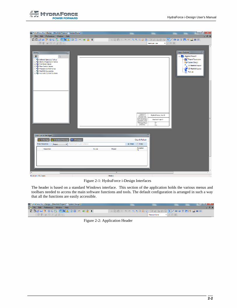
Figure 2-1: HydraForce i-Design Interfaces
The header is based on a standard Windows interface. This section of the application holds the various menus and
toolbars needed to access the main software functions and tools. The default configuration is arranged in such a way
that all the functions are easily accessible.
Figure 2-2: Application Header

HydraForce i-Design User's Manual
2-3
2.1.1 Menus
The menus found in i-Design works as any other standard Windows application. There are five or six menus,
depending on the active interface.
1. File
2. Edit
3. Preferences
4. Manifold Layout
5. Window
6. Help
Figure 2-3: Common Menus
Figure 2-4: Menus in the Manifold Layout Interfaces
2.1.1.1 Contents of the Menus
Menus contents are:
1. File
New
o Price a Manifold
o Price Components
Open File
Close File
Save File
Save File As
I-Design Web
o Open From i-Design Web
o Save to i-Design Web
o Manage i-Design Web User Account
Revision
Import / Export
o Export Current View to DXF
o Export Formatted Schematic to DXF
o Export 3D Components to Folder
o Export 3D Components to STEP
o Export to XML 3D
HydraForce i-Design User's Manual
2-4
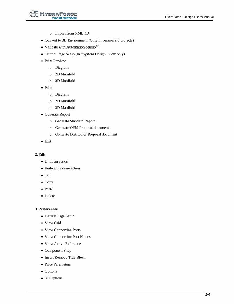
o Import from XML 3D
Convert to 3D Environment (Only in version 2.0 projects)
Validate with Automation StudioTM
Current Page Setup (In “System Design” view only)
Print Preview
o Diagram
o 2D Manifold
o 3D Manifold
o Diagram
o 2D Manifold
o 3D Manifold
Generate Report
o Generate Standard Report
o Generate OEM Proposal document
o Generate Distributor Proposal document
Exit
2. Edit
Undo an action
Redo an undone action
Cut
Copy
Paste
Delete
3. Preferences
Default Page Setup
View Grid
View Connection Ports
View Connection Port Names
View Active Reference
Component Snap
Insert/Remove Title Block
Price Parameters
Options
3D Options
HydraForce i-Design User's Manual
2-5
4. Manifold Layout
Transparency
View Components
View Components ID
View Satellites Owner
View Interferences
View References Axis
Set Manifold Dimensions
Manifold Grid Properties
Set Location
Set Angle
Counterboring
5. Window
Horizontal Tile
Vertical Tile
Cascade
6. Help
I-Design Help
HydraForce, Inc. Website
Software Registration
Check for Update
About
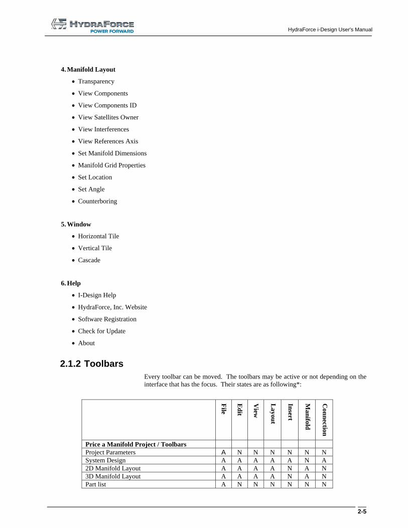
2.1.2 Toolbars
Every toolbar can be moved. The toolbars may be active or not depending on the
interface that has the focus. Their states are as following*:
File
Ed
it
View
La
yo
ut
Insert
Ma
nifo
ld
Co
nn
ection
Price a Manifold Project / Toolbars
Project Parameters A N N N N N N
System Design A A A A A N A
2D Manifold Layout A A A A N A N
3D Manifold Layout A A A A N A N
Part list A N N N N N N
HydraForce i-Design User's Manual
2-6
Price Components Project / Toolbars
Project Parameters A N N N N N N
Price Components A N N N N N N
*A = Active, N=Not Active
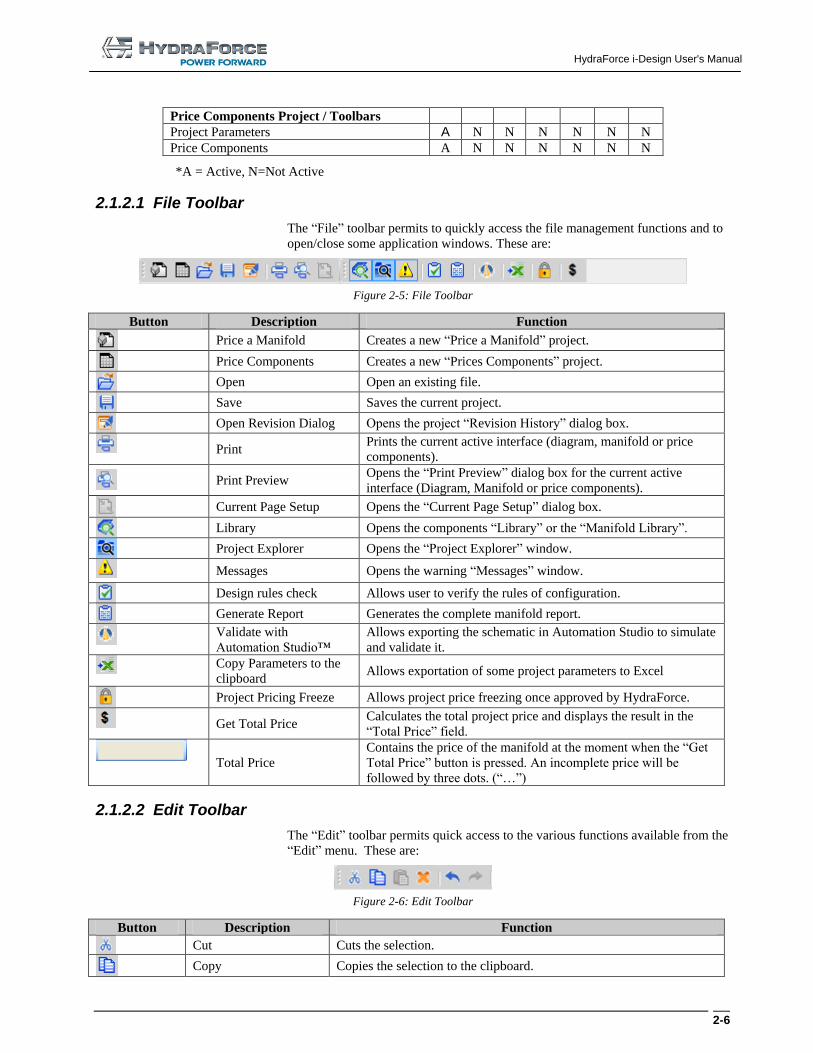
2.1.2.1 File Toolbar
The “File” toolbar permits to quickly access the file management functions and to
open/close some application windows. These are:
Figure 2-5: File Toolbar
Button Description Function
Price a Manifold Creates a new “Price a Manifold” project.
Price Components Creates a new “Prices Components” project.
Open Open an existing file.
Save Saves the current project.
Open Revision Dialog Opens the project “Revision History” dialog box.
Print Prints the current active interface (diagram, manifold or price
components).
Print Preview Opens the “Print Preview” dialog box for the current active
interface (Diagram, Manifold or price components).
Current Page Setup Opens the “Current Page Setup” dialog box.
Library Opens the components “Library” or the “Manifold Library”.
Project Explorer Opens the “Project Explorer” window.
Messages Opens the warning “Messages” window.
Design rules check Allows user to verify the rules of configuration.
Generate Report Generates the complete manifold report.
Validate with
Automation Studio™
Allows exporting the schematic in Automation Studio to simulate
and validate it.
Copy Parameters to the
clipboard Allows exportation of some project parameters to Excel
Project Pricing Freeze Allows project price freezing once approved by HydraForce.
Get Total Price Calculates the total project price and displays the result in the
“Total Price” field.
Total Price
Contains the price of the manifold at the moment when the “Get
Total Price” button is pressed. An incomplete price will be
followed by three dots. (“…”)
2.1.2.2 Edit Toolbar
The “Edit” toolbar permits quick access to the various functions available from the
“Edit” menu. These are:
Figure 2-6: Edit Toolbar
Button Description Function
Cut Cuts the selection.
Copy Copies the selection to the clipboard.
HydraForce i-Design User's Manual
2-7
Button Description Function
Paste Pastes the contents from the clipboard.
Delete Deletes the selection.
Undo Undo the last actions (i.e. Cut, Paste, Delete, Position, Size and Rotate
a component as well as links).
Redo Redo an undone action.
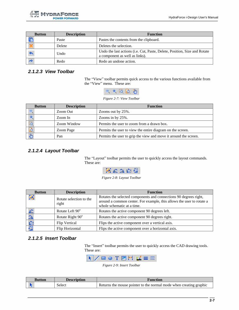
2.1.2.3 View Toolbar
The “View” toolbar permits quick access to the various functions available from
the “View” menu. These are:
Figure 2-7: View Toolbar
Button Description Function
Zoom Out Zooms out by 25%.
Zoom In Zooms in by 25%.
Zoom Window Permits the user to zoom from a drawn box.
Zoom Page Permits the user to view the entire diagram on the screen.
Pan Permits the user to grip the view and move it around the screen.
2.1.2.4 Layout Toolbar
The “Layout” toolbar permits the user to quickly access the layout commands.
These are:
Figure 2-8: Layout Toolbar
Button Description Function
Rotate selection to the
right
Rotates the selected components and connections 90 degrees right,
around a common center. For example, this allows the user to rotate a
whole schematic at a time.
Rotate Left 90o Rotates the active component 90 degrees left.
Rotate Right 90o Rotates the active component 90 degrees right.
Flip Vertical Flips the active component over a vertical axis.
Flip Horizontal Flips the active component over a horizontal axis.
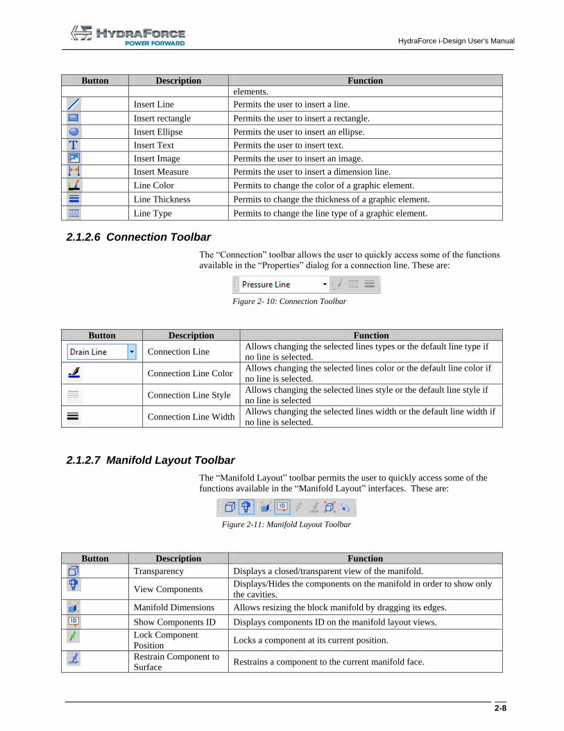
2.1.2.5 Insert Toolbar
The “Insert” toolbar permits the user to quickly access the CAD drawing tools.
These are:
Figure 2-9: Insert Toolbar
Button Description Function
Select Returns the mouse pointer to the normal mode when creating graphic
HydraForce i-Design User's Manual
2-8
Button Description Function
elements.
Insert Line Permits the user to insert a line.
Insert rectangle Permits the user to insert a rectangle.
Insert Ellipse Permits the user to insert an ellipse.
Insert Text Permits the user to insert text.
Insert Image Permits the user to insert an image.
Insert Measure Permits the user to insert a dimension line.
Line Color Permits to change the color of a graphic element.
Line Thickness Permits to change the thickness of a graphic element.
Line Type Permits to change the line type of a graphic element.
2.1.2.6 Connection Toolbar
The “Connection” toolbar allows the user to quickly access some of the functions
available in the “Properties” dialog for a connection line. These are:
Figure 2- 10: Connection Toolbar
Button Description Function
Connection Line
Allows changing the selected lines types or the default line type if
no line is selected.
Connection Line Color
Allows changing the selected lines color or the default line color if
no line is selected.
Connection Line Style
Allows changing the selected lines style or the default line style if
no line is selected
Connection Line Width
Allows changing the selected lines width or the default line width if
no line is selected.
2.1.2.7 Manifold Layout Toolbar
The “Manifold Layout” toolbar permits the user to quickly access some of the
functions available in the “Manifold Layout” interfaces. These are:
Figure 2-11: Manifold Layout Toolbar
Button Description Function
Transparency Displays a closed/transparent view of the manifold.
View Components Displays/Hides the components on the manifold in order to show only
the cavities.
Manifold Dimensions Allows resizing the block manifold by dragging its edges.
Show Components ID Displays components ID on the manifold layout views.
Lock Component
Position Locks a component at its current position.
Restrain Component to
Surface Restrains a component to the current manifold face.
HydraForce i-Design User's Manual
2-9
Button Description Function
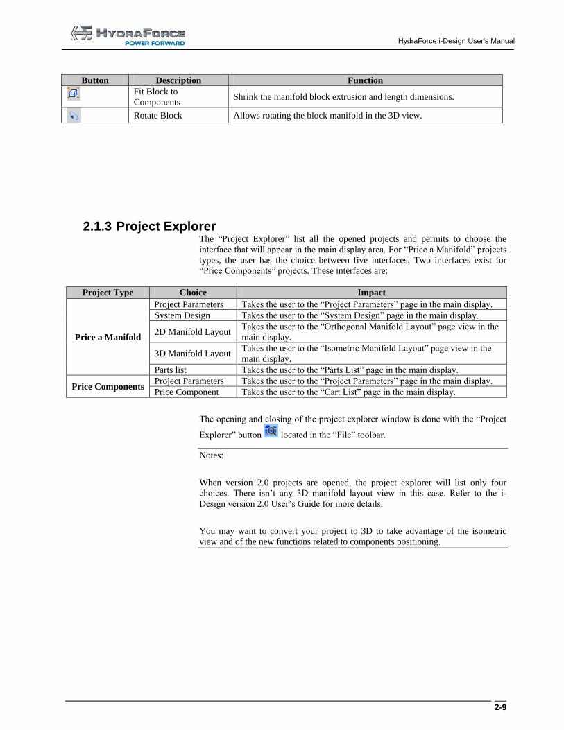
Fit Block to
Components Shrink the manifold block extrusion and length dimensions.
Rotate Block Allows rotating the block manifold in the 3D view.
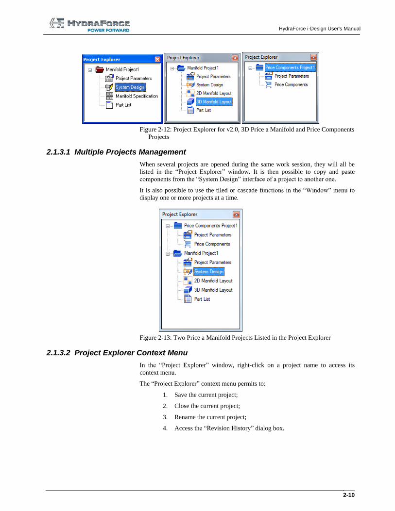
2.1.3 Project Explorer The “Project Explorer” list all the opened projects and permits to choose the
interface that will appear in the main display area. For “Price a Manifold” projects
types, the user has the choice between five interfaces. Two interfaces exist for
“Price Components” projects. These interfaces are:
Project Type Choice Impact
Price a Manifold
Project Parameters Takes the user to the “Project Parameters” page in the main display.
System Design Takes the user to the “System Design” page in the main display.
2D Manifold Layout Takes the user to the “Orthogonal Manifold Layout” page view in the
main display.
3D Manifold Layout Takes the user to the “Isometric Manifold Layout” page view in the
main display.
Parts list Takes the user to the “Parts List” page in the main display.
Price Components Project Parameters Takes the user to the “Project Parameters” page in the main display.
Price Component Takes the user to the “Cart List” page in the main display.
The opening and closing of the project explorer window is done with the “Project
Explorer” button located in the “File” toolbar.
Notes:
When version 2.0 projects are opened, the project explorer will list only four
choices. There isn’t any 3D manifold layout view in this case. Refer to the i-
Design version 2.0 User’s Guide for more details.
You may want to convert your project to 3D to take advantage of the isometric
view and of the new functions related to components positioning.
HydraForce i-Design User's Manual
2-10
Figure 2-12: Project Explorer for v2.0, 3D Price a Manifold and Price Components
Projects
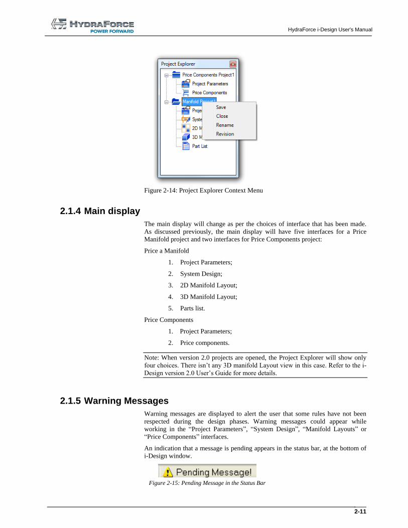
2.1.3.1 Multiple Projects Management
When several projects are opened during the same work session, they will all be
listed in the “Project Explorer” window. It is then possible to copy and paste
components from the “System Design” interface of a project to another one.
It is also possible to use the tiled or cascade functions in the “Window” menu to
display one or more projects at a time.
Figure 2-13: Two Price a Manifold Projects Listed in the Project Explorer
2.1.3.2 Project Explorer Context Menu
In the “Project Explorer” window, right-click on a project name to access its
context menu.
The “Project Explorer” context menu permits to:
1. Save the current project;
2. Close the current project;
3. Rename the current project;
4. Access the “Revision History” dialog box.
HydraForce i-Design User's Manual
2-11
Figure 2-14: Project Explorer Context Menu
2.1.4 Main display
The main display will change as per the choices of interface that has been made.
As discussed previously, the main display will have five interfaces for a Price
Manifold project and two interfaces for Price Components project:
Price a Manifold
1. Project Parameters;
2. System Design;
3. 2D Manifold Layout;
4. 3D Manifold Layout;
5. Parts list.
Price Components
1. Project Parameters;
2. Price components.
Note: When version 2.0 projects are opened, the Project Explorer will show only
four choices. There isn’t any 3D manifold Layout view in this case. Refer to the i-
Design version 2.0 User’s Guide for more details.
2.1.5 Warning Messages
Warning messages are displayed to alert the user that some rules have not been
respected during the design phases. Warning messages could appear while
working in the “Project Parameters”, “System Design”, “Manifold Layouts” or
“Price Components” interfaces.
An indication that a message is pending appears in the status bar, at the bottom of
i-Design window.
Figure 2-15: Pending Message in the Status Bar
HydraForce i-Design User's Manual
2-12
To make the warning disappear from the status bar, you need to open the
“Messages” window. There is two ways to open it:
1. Click on the warning message directly in the status bar;
2. Click on the “Messages” button in the “File” toolbar. This will open the
“Messages” windows if it was closed or close it if it was opened.
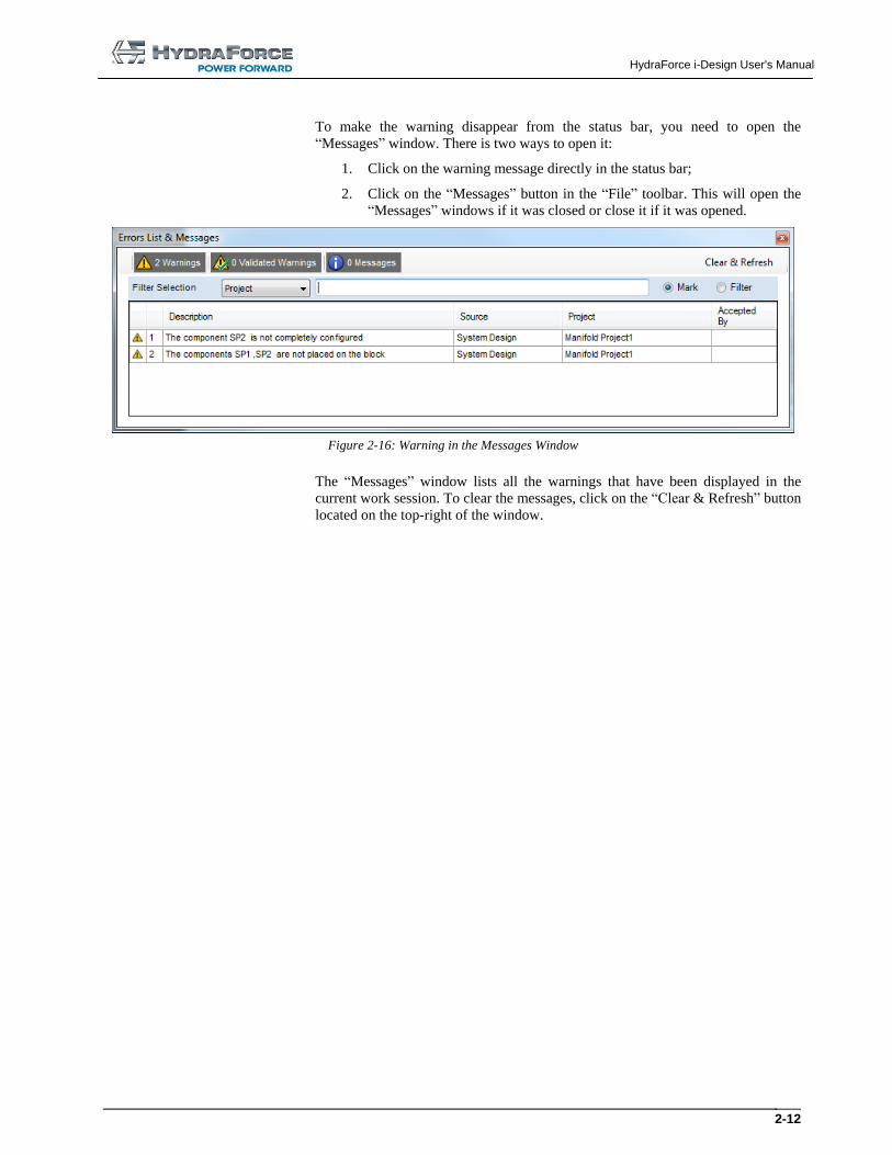
Figure 2-16: Warning in the Messages Window
The “Messages” window lists all the warnings that have been displayed in the
current work session. To clear the messages, click on the “Clear & Refresh” button
located on the top-right of the window.
HydraForce i-Design User's Manual
2-13
2.2 Working with Project Files
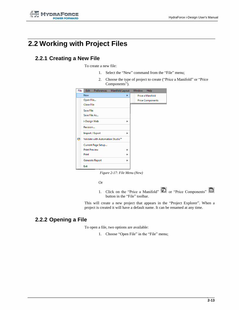
2.2.1 Creating a New File
To create a new file:
1. Select the “New” command from the “File” menu;
2. Choose the type of project to create (“Price a Manifold” or “Price
Components”).
Figure 2-17: File Menu (New)
Or
1. Click on the “Price a Manifold” or “Price Components”
button in the “File” toolbar.
This will create a new project that appears in the “Project Explorer”. When a
project is created it will have a default name. It can be renamed at any time.
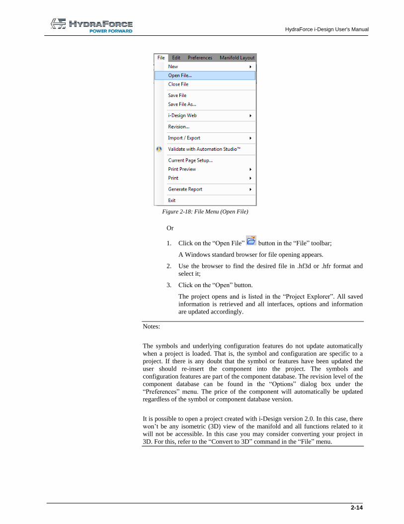
2.2.2 Opening a File
To open a file, two options are available:
1. Choose “Open File” in the “File” menu;
HydraForce i-Design User's Manual
2-14
Figure 2-18: File Menu (Open File)
Or
1. Click on the “Open File” button in the “File” toolbar;
A Windows standard browser for file opening appears.
2. Use the browser to find the desired file in .hf3d or .hfr format and
select it;
3. Click on the “Open” button.
The project opens and is listed in the “Project Explorer”. All saved
information is retrieved and all interfaces, options and information
are updated accordingly.
Notes:
The symbols and underlying configuration features do not update automatically
when a project is loaded. That is, the symbol and configuration are specific to a
project. If there is any doubt that the symbol or features have been updated the
user should re-insert the component into the project. The symbols and
configuration features are part of the component database. The revision level of the
component database can be found in the “Options” dialog box under the
“Preferences” menu. The price of the component will automatically be updated
regardless of the symbol or component database version.
It is possible to open a project created with i-Design version 2.0. In this case, there
won’t be any isometric (3D) view of the manifold and all functions related to it
will not be accessible. In this case you may consider converting your project in
3D. For this, refer to the “Convert to 3D” command in the “File” menu.
HydraForce i-Design User's Manual
2-15
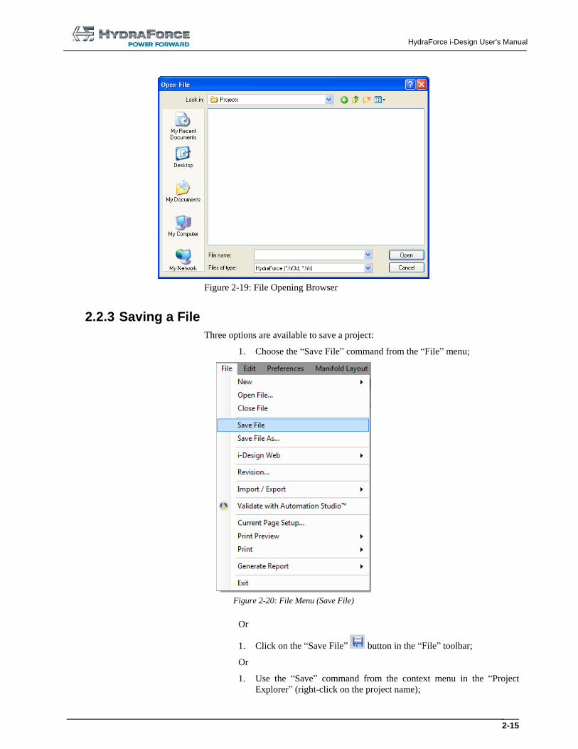
Figure 2-19: File Opening Browser
2.2.3 Saving a File
Three options are available to save a project:
1. Choose the “Save File” command from the “File” menu;
Figure 2-20: File Menu (Save File)
Or
1. Click on the “Save File” button in the “File” toolbar;
Or
1. Use the “Save” command from the context menu in the “Project
Explorer” (right-click on the project name);
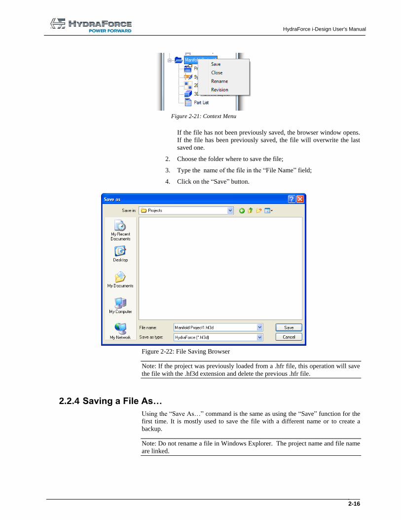
HydraForce i-Design User's Manual
2-16
Figure 2-21: Context Menu
If the file has not been previously saved, the browser window opens.
If the file has been previously saved, the file will overwrite the last
saved one.
2. Choose the folder where to save the file;
3. Type the name of the file in the “File Name” field;
4. Click on the “Save” button.
Figure 2-22: File Saving Browser
Note: If the project was previously loaded from a .hfr file, this operation will save
the file with the .hf3d extension and delete the previous .hfr file.
2.2.4 Saving a File As…
Using the “Save As…” command is the same as using the “Save” function for the
first time. It is mostly used to save the file with a different name or to create a
backup.
Note: Do not rename a file in Windows Explorer. The project name and file name
are linked.
HydraForce i-Design User's Manual
2-17
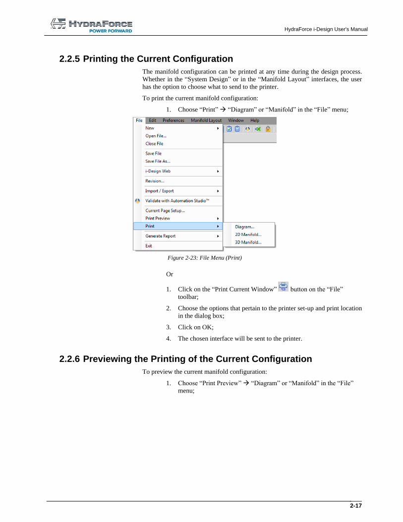
2.2.5 Printing the Current Configuration
The manifold configuration can be printed at any time during the design process.
Whether in the “System Design” or in the “Manifold Layout” interfaces, the user
has the option to choose what to send to the printer.
To print the current manifold configuration:
1. Choose “Print” “Diagram” or “Manifold” in the “File” menu;
Figure 2-23: File Menu (Print)
Or
1. Click on the “Print Current Window” button on the “File”
toolbar;
2. Choose the options that pertain to the printer set-up and print location
in the dialog box;
3. Click on OK;
4. The chosen interface will be sent to the printer.
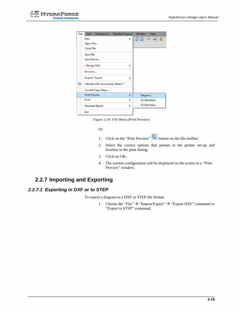
2.2.6 Previewing the Printing of the Current Configuration
To preview the current manifold configuration:
1. Choose “Print Preview” “Diagram” or “Manifold” in the “File”
menu;
HydraForce i-Design User's Manual
2-18
Figure 2-24: File Menu (Print Preview)
Or
1. Click on the “Print Preview” button on the file toolbar;
2. Select the correct options that pertain to the printer set-up and
location in the print dialog;
3. Click on OK;
4. The current configuration will be displayed on the screen in a “Print
Preview” window;
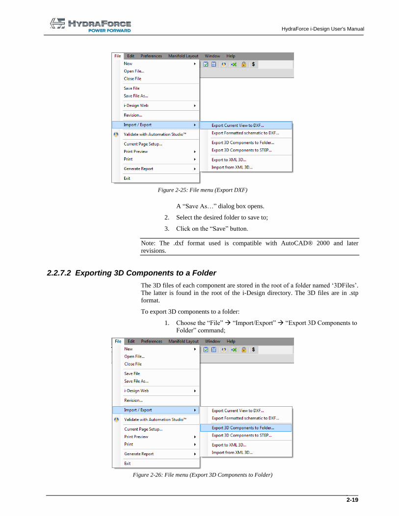
2.2.7 Importing and Exporting
2.2.7.1 Exporting in DXF or to STEP
To export a diagram to a DXF or STEP file format:
1. Choose the “File” “Import/Export” “Export DXF” command or
“Export to STEP” command;
HydraForce i-Design User's Manual
2-19
Figure 2-25: File menu (Export DXF)
A “Save As…” dialog box opens.
2. Select the desired folder to save to;
3. Click on the “Save” button.
Note: The .dxf format used is compatible with AutoCAD® 2000 and later
revisions.
2.2.7.2 Exporting 3D Components to a Folder
The 3D files of each component are stored in the root of a folder named ‘3DFiles’.
The latter is found in the root of the i-Design directory. The 3D files are in .stp
format.
To export 3D components to a folder:
1. Choose the “File” “Import/Export” “Export 3D Components to
Folder” command;
Figure 2-26: File menu (Export 3D Components to Folder)
HydraForce i-Design User's Manual
2-20
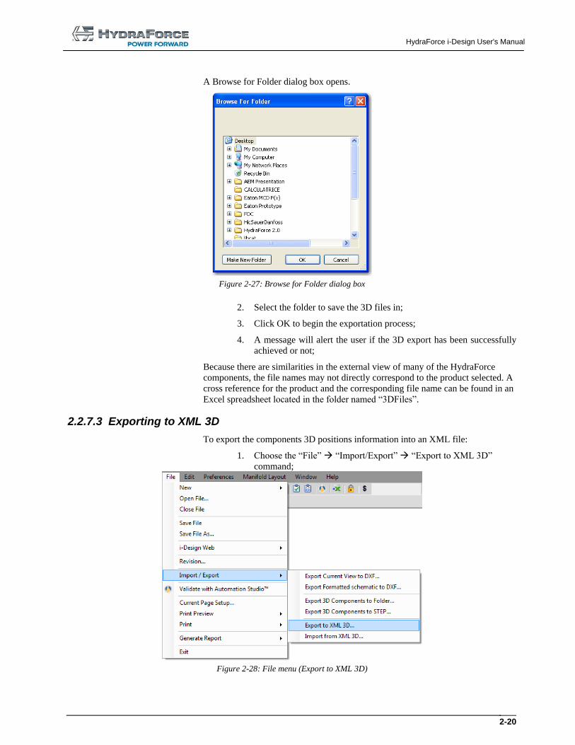
A Browse for Folder dialog box opens.
Figure 2-27: Browse for Folder dialog box
2. Select the folder to save the 3D files in;
3. Click OK to begin the exportation process;
4. A message will alert the user if the 3D export has been successfully
achieved or not;
Because there are similarities in the external view of many of the HydraForce
components, the file names may not directly correspond to the product selected. A
cross reference for the product and the corresponding file name can be found in an
Excel spreadsheet located in the folder named “3DFiles”.
2.2.7.3 Exporting to XML 3D
To export the components 3D positions information into an XML file:
1. Choose the “File” “Import/Export” “Export to XML 3D”
command;
Figure 2-28: File menu (Export to XML 3D)
HydraForce i-Design User's Manual
2-21
A “Save As” dialog box opens.
2. Select the folder to save to;
3. Click on the “Save” button.
Note: All the components are exported to the XML file, even if they are not
inserted on the manifold block.
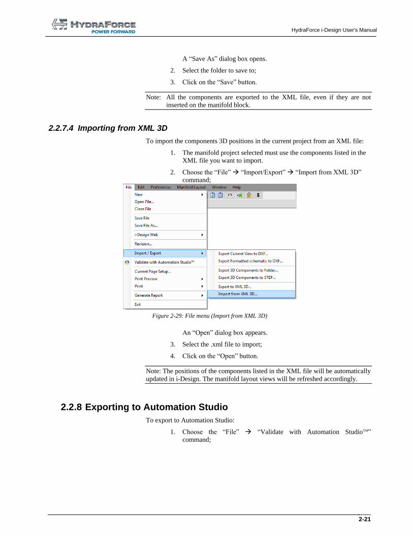
2.2.7.4 Importing from XML 3D
To import the components 3D positions in the current project from an XML file:
1. The manifold project selected must use the components listed in the
XML file you want to import.
2. Choose the “File” “Import/Export” “Import from XML 3D”
command;
Figure 2-29: File menu (Import from XML 3D)
An “Open” dialog box appears.
3. Select the .xml file to import;
4. Click on the “Open” button.
Note: The positions of the components listed in the XML file will be automatically
updated in i-Design. The manifold layout views will be refreshed accordingly.
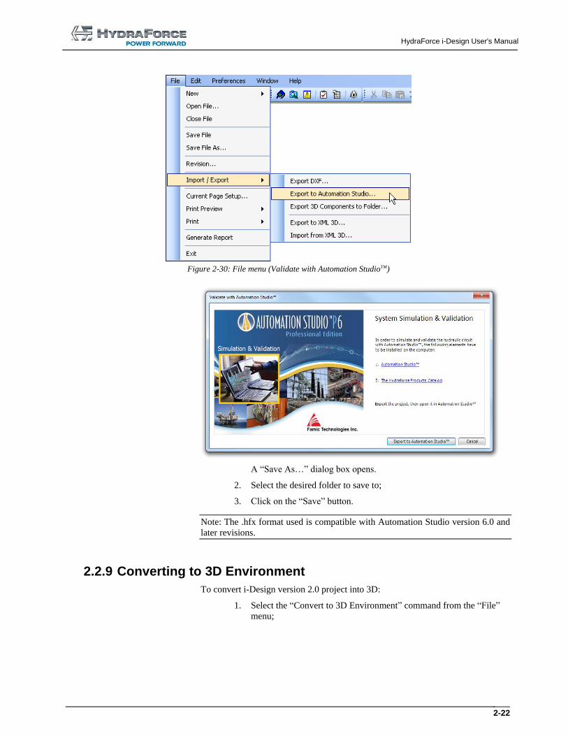
2.2.8 Exporting to Automation Studio
To export to Automation Studio:
1. Choose the “File” “Validate with Automation StudioTM”
command;
HydraForce i-Design User's Manual
2-22
Figure 2-30: File menu (Validate with Automation StudioTM)
A “Save As…” dialog box opens.
2. Select the desired folder to save to;
3. Click on the “Save” button.
Note: The .hfx format used is compatible with Automation Studio version 6.0 and
later revisions.
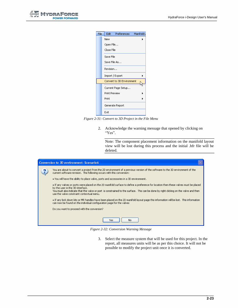
2.2.9 Converting to 3D Environment
To convert i-Design version 2.0 project into 3D:
1. Select the “Convert to 3D Environment” command from the “File”
menu;
HydraForce i-Design User's Manual
2-23
Figure 2-31: Convert to 3D Project in the File Menu
2. Acknowledge the warning message that opened by clicking on
“Yes”.
Note: The component placement information on the manifold layout
view will be lost during this process and the initial .hfr file will be
deleted.
Figure 2-32: Conversion Warning Message
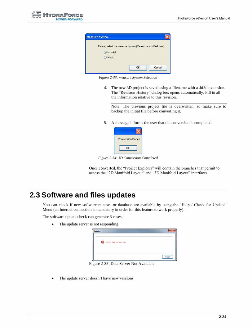
3. Select the measure system that will be used for this project. In the
report, all measures units will be as per this choice. It will not be
possible to modify the project unit once it is converted.
HydraForce i-Design User's Manual
2-24
Figure 2-33: measure System Selection
4. The new 3D project is saved using a filename with a .hf3d extension.
The “Revision History” dialog box opens automatically. Fill in all
the information relative to this revision.
Note: The previous project file is overwritten, so make sure to
backup the initial file before converting it.
5. A message informs the user that the conversion is completed.
Figure 2-34: 3D Conversion Completed
Once converted, the “Project Explorer” will contain the branches that permit to
access the “2D Manifold Layout” and “3D Manifold Layout” interfaces.
2.3 Software and files updates You can check if new software releases or database are available by using the “Help / Check for Update”
Menu (an Internet connection is mandatory in order for this feature to work properly).
The software update check can generate 3 cases:
The update server is not responding
Figure 2-35: Data Server Not Available
The update server doesn’t have new versions
HydraForce i-Design User's Manual
3-25
Figure 2-36: Software is Up-to-date
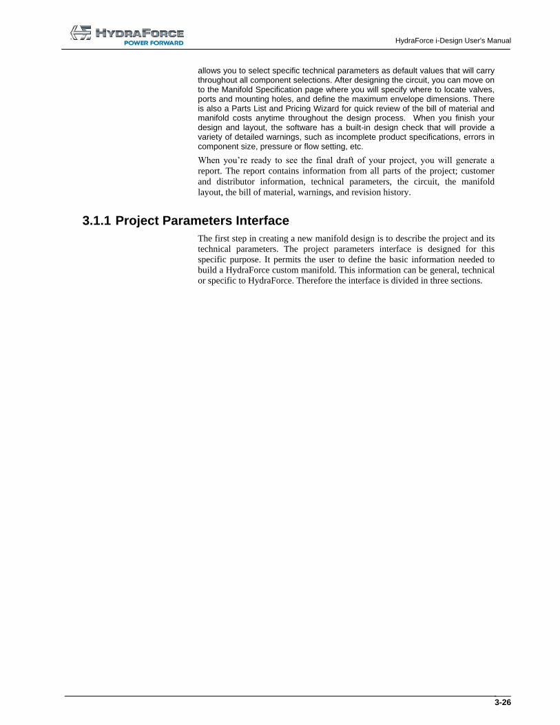
The update server has an available update
Figure 2-37: Software Updates are Available
You can click on the “i-Design Installation Package – v4.X.X.XXXX” button or the “US Price –
vX.X.XXXX” button when available; otherwise the window can only be closed. This action launches the
current browser with the Hydraforce server address. Then the user can download the latest version and install it
in its computer (i-Design needs to be closed prior to the update operation).
3 Building a First Project
3.1 Creating a Manifold Project When you begin a new project, you will start on the System Design page where you can quickly and easily create your circuit using drag-and- drop technology. Or you may choose to start on the Project Parameters page where i-Design
HydraForce i-Design User's Manual
3-26
allows you to select specific technical parameters as default values that will carry throughout all component selections. After designing the circuit, you can move on to the Manifold Specification page where you will specify where to locate valves, ports and mounting holes, and define the maximum envelope dimensions. There is also a Parts List and Pricing Wizard for quick review of the bill of material and manifold costs anytime throughout the design process. When you finish your design and layout, the software has a built-in design check that will provide a variety of detailed warnings, such as incomplete product specifications, errors in component size, pressure or flow setting, etc.
When you’re ready to see the final draft of your project, you will generate a
report. The report contains information from all parts of the project; customer
and distributor information, technical parameters, the circuit, the manifold
layout, the bill of material, warnings, and revision history.
3.1.1 Project Parameters Interface
The first step in creating a new manifold design is to describe the project and its
technical parameters. The project parameters interface is designed for this
specific purpose. It permits the user to define the basic information needed to
build a HydraForce custom manifold. This information can be general, technical
or specific to HydraForce. Therefore the interface is divided in three sections.
HydraForce i-Design User's Manual
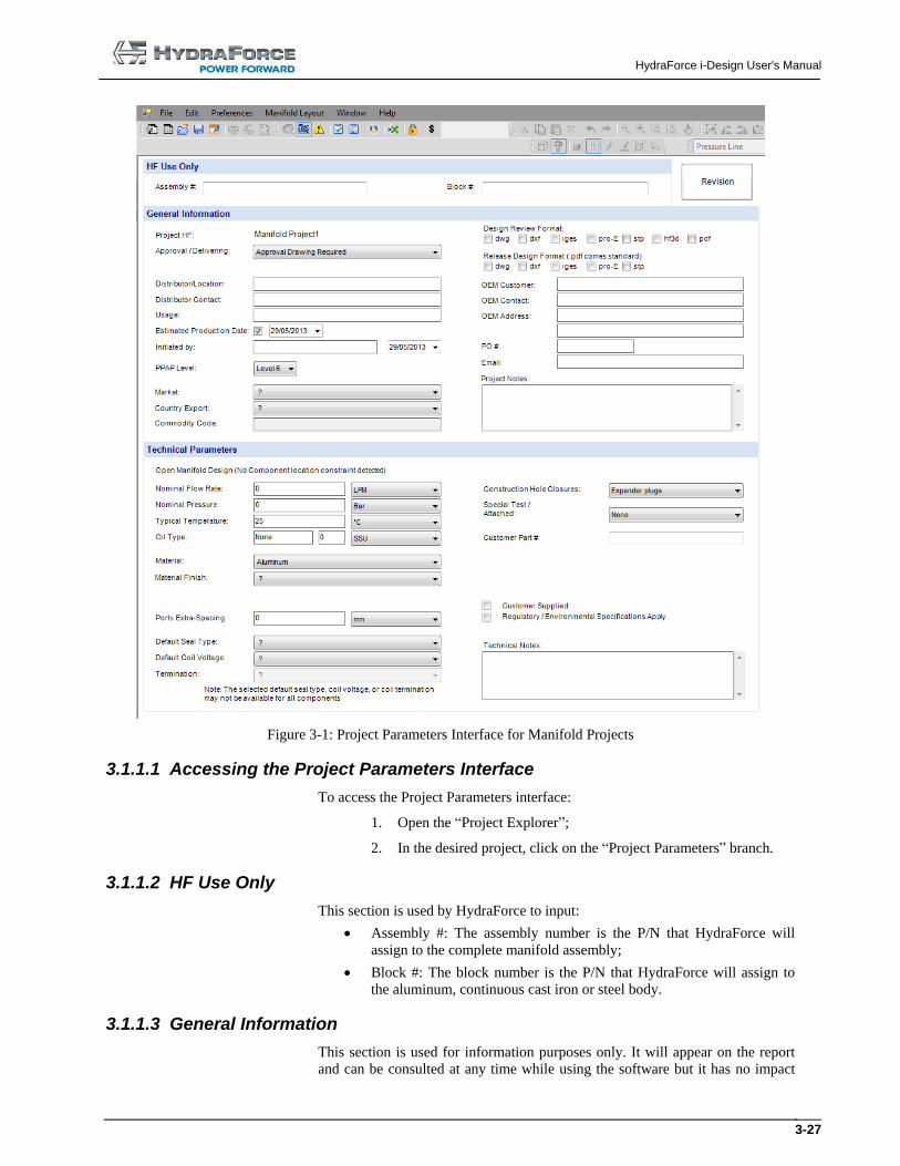
3-27
Figure 3-1: Project Parameters Interface for Manifold Projects
3.1.1.1 Accessing the Project Parameters Interface
To access the Project Parameters interface:
1. Open the “Project Explorer”;
2. In the desired project, click on the “Project Parameters” branch.
3.1.1.2 HF Use Only
This section is used by HydraForce to input:
Assembly #: The assembly number is the P/N that HydraForce will
assign to the complete manifold assembly;
Block #: The block number is the P/N that HydraForce will assign to
the aluminum, continuous cast iron or steel body.
3.1.1.3 General Information
This section is used for information purposes only. It will appear on the report
and can be consulted at any time while using the software but it has no impact
HydraForce i-Design User's Manual
3-28
on the choices offered to the user during the design process. Fields found in this
section of the interface permit the user to define:
Project HF (Same as the filename);
Approval / Delivering field with these choices:
o Approval drawing required;
o No Approval Drawing – Release Drawing;
o “Fast-Track” Delivered – No approval Drawing (PO required).
Design Review Format (DWG, DXF, Iges, Pro-E, STEP, hf3d and
PDF);
Released Design format (DWG, DXF, Iges, Pro-E and STEP);
Distributor/Location;
OEM Customer;
Distributor Contact;
OEM Contact;
OEM Address;
Email;
Estimated Annual Usage;
Estimated Production Date;
PO#;
Initiated By and Date;
Additional project notes;
PPAP Level (Selection list from level 1 to level 6, with level 6 as
default).
Market
Country Export
Commodity Code
3.1.1.4 Technical Project Parameters
Technical project parameters are used as reference while the user is designing
the system. Therefore, the choices made / entered in this section of the interface
will have an impact on the design process. Fields found in this section of the
interface permit the user to define:
Nominal Flow Rate;
Nominal Pressure;
Oil Type and viscosity;
Typical (operating) Temperature;
Ports Extra-Spacing;
Default Value for Seal Type;
Default Value for Coil Voltage;
Default Value for Coil termination;
Material:
o Aluminum (Default if the nominal pressure is less than or
equal to 3499 psi);
o Durabar: CC SG Iron (Default if the nominal pressure is
greater or equal to 3500 psi) ;
HydraForce i-Design User's Manual
3-29
o Steel.
Material Finish;
Special Port Spacing for Fittings;
Construction Hole Closures:
o SAE threaded plugs (Automatically selected if the Nominal
pressure is greater or equal to 3500 psi);
o Expander plugs (Automatically selected as default if the
Nominal pressure is less than or equal to 3499 psi). The user
has the possibility to change it back to Expander plugs.
Special Test/Certification Requirements Attached:
o None;
o Prototype only;
o Production.
Customer P/N:
o Shown on block:
With HF number;
Without HF number.
o Not shown on block :
With HF number.
Regulatory / Environmental Specifications Apply;
Technical Notes.
3.1.1.5 Selecting Default Values
Default values are selected so that they will appear by default in the component
properties interface. If a selection is made and it happens that it does not exist in
the component options, the first option available will be selected by default. The
fields, which a default value can be set for are:
1. Seal Type;
2. Coil Voltage;
3. Coil Termination.
Note: Default values can be overwritten during the configuration process.
3.1.2 System Design Interface
The system design interface permits to design the actual hydraulic circuit that
will compose the HydraForce custom manifold. The system design interface is
split into two major parts:
1. The parts library;
2. The diagram editor.
3.1.2.1 Accessing the Main Design Interface
To access the main design interface:
1. Click on the “Project Explorer” button on the “File” toolbar;
2. In the desired project, click on the “System Design” branch.
HydraForce i-Design User's Manual
3-30
The main display will show the design interface.
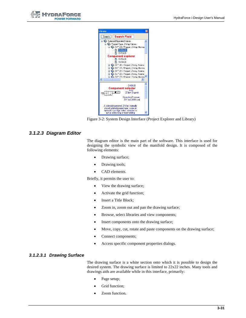
3.1.2.2 Parts Library
The “Library Explorer” is the main tool for selecting components and building
circuits. To access the “Library Explorer”:
1. Click on the “Library Explorer” button on the “File” toolbar;
2. Browse the various categories using the + sign and selecting
various categories in the library.
Or
Use the search engine to find the component you want.
Components and their description / model code appear in the
component viewer / selector window.
Note: The contents of the library will change depending on the selected interface
and project type currently used.
3.1.2.2.1 Search Field
The search field permits the user to search through the library for a specific
string. When the search is started from anywhere in the library, the search
engine will close the search loop by restarting from the beginning.
3.1.2.2.2 Library Explorer
The “Library Explorer” is a navigational tool. It permits the user to:
View different component categories;
Expand / Retract component categories.
3.1.2.2.3 Component Selector
The component selector permits the user to:
Visualize the component symbols;
Visualize the component description. If selected in the subfolder, the
complete component description is shown;
The component selector permits the user to drag and drop a component
onto the design surface. (See the Working with Components chapter)
HydraForce i-Design User's Manual
3-31
Figure 3-2: System Design Interface (Project Explorer and Library)
3.1.2.3 Diagram Editor
The diagram editor is the main part of the software. This interface is used for
designing the symbolic view of the manifold design. It is composed of the
following elements:
Drawing surface;
Drawing tools;
CAD elements.
Briefly, it permits the user to:
View the drawing surface;
Activate the grid function;
Insert a Title Block;
Zoom in, zoom out and pan the drawing surface;
Browse, select libraries and view components;
Insert components onto the drawing surface;
Move, copy, cut, rotate and paste components on the drawing surface;
Connect components;
Access specific component properties dialogs.
3.1.2.3.1 Drawing Surface
The drawing surface is a white section onto which it is possible to design the
desired system. The drawing surface is limited to 22x22 inches. Many tools and
drawings aids are available while in this interface, primarily:
Page setup;
Grid function;
Zoom function.
HydraForce i-Design User's Manual
3-32
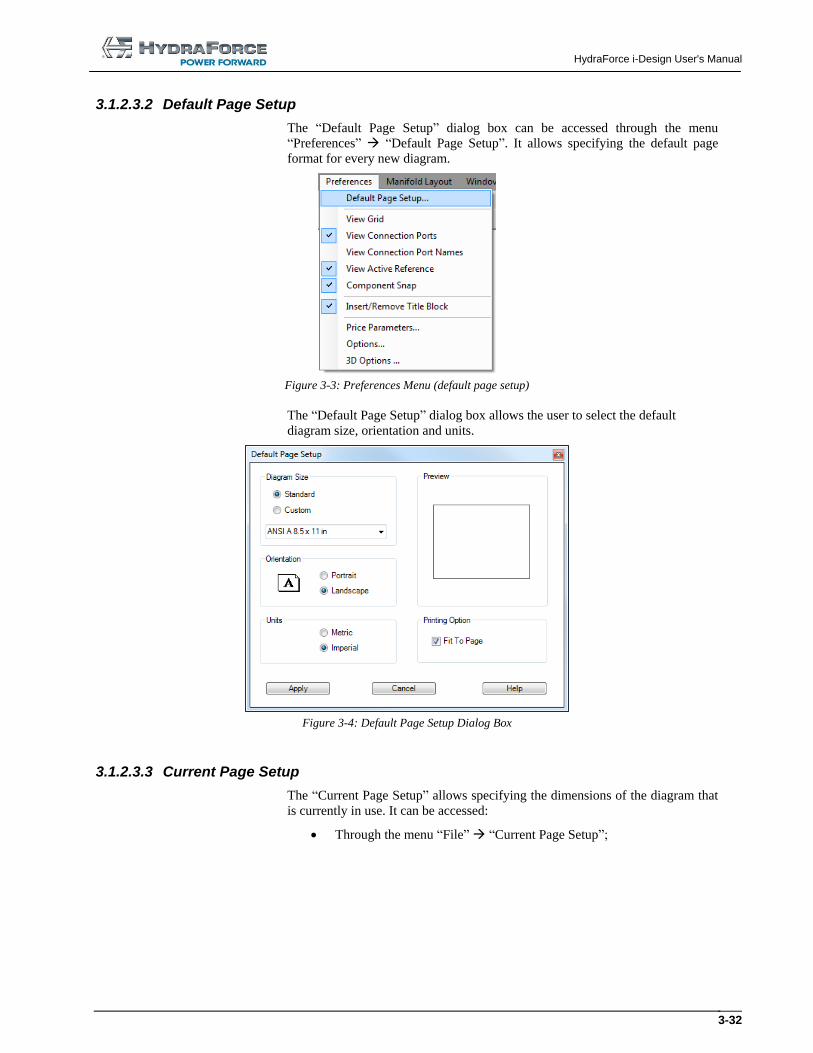
3.1.2.3.2 Default Page Setup
The “Default Page Setup” dialog box can be accessed through the menu
“Preferences” “Default Page Setup”. It allows specifying the default page
format for every new diagram.
Figure 3-3: Preferences Menu (default page setup)
The “Default Page Setup” dialog box allows the user to select the default
diagram size, orientation and units.
Figure 3-4: Default Page Setup Dialog Box
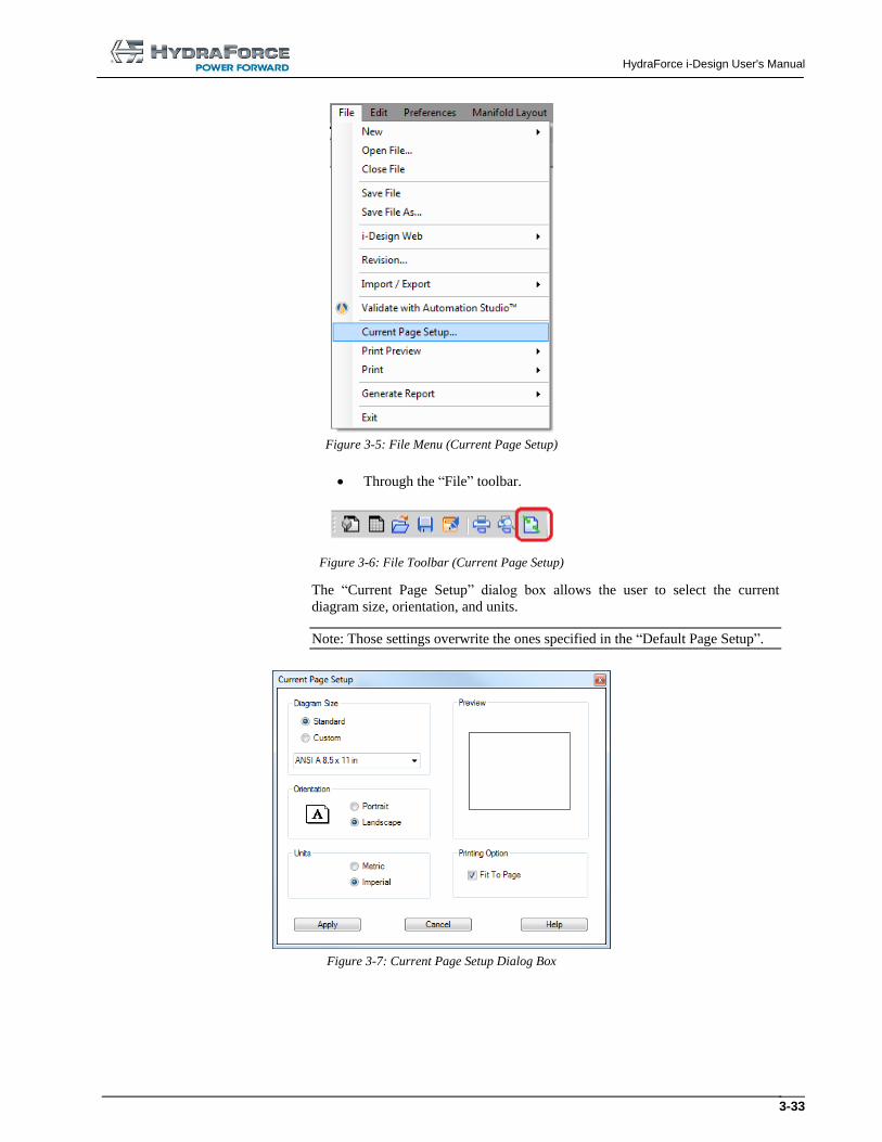
3.1.2.3.3 Current Page Setup
The “Current Page Setup” allows specifying the dimensions of the diagram that
is currently in use. It can be accessed:
Through the menu “File” “Current Page Setup”;
HydraForce i-Design User's Manual
3-33
Figure 3-5: File Menu (Current Page Setup)
Through the “File” toolbar.
Figure 3-6: File Toolbar (Current Page Setup)
The “Current Page Setup” dialog box allows the user to select the current
diagram size, orientation, and units.
Note: Those settings overwrite the ones specified in the “Default Page Setup”.
Figure 3-7: Current Page Setup Dialog Box
HydraForce i-Design User's Manual
3-34
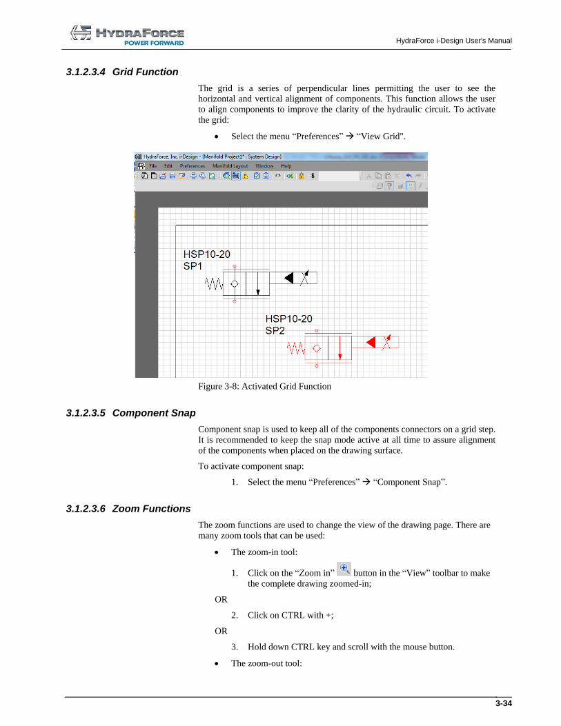
3.1.2.3.4 Grid Function
The grid is a series of perpendicular lines permitting the user to see the
horizontal and vertical alignment of components. This function allows the user
to align components to improve the clarity of the hydraulic circuit. To activate
the grid:
Select the menu “Preferences” “View Grid".
Figure 3-8: Activated Grid Function
3.1.2.3.5 Component Snap
Component snap is used to keep all of the components connectors on a grid step.
It is recommended to keep the snap mode active at all time to assure alignment
of the components when placed on the drawing surface.
To activate component snap:
1. Select the menu “Preferences” “Component Snap”.
3.1.2.3.6 Zoom Functions
The zoom functions are used to change the view of the drawing page. There are
many zoom tools that can be used:
The zoom-in tool:
1. Click on the “Zoom in” button in the “View” toolbar to make
the complete drawing zoomed-in;
OR
2. Click on CTRL with +;
OR
3. Hold down CTRL key and scroll with the mouse button.
The zoom-out tool:
HydraForce i-Design User's Manual
3-35
1. Click on the “Zoom out” button in the “View” toolbar to make
the complete drawing zoomed-out;
OR
2. Click on CTRL with -;
OR
3. Hold down CTRL and scroll with the mouse button.
The zoom box tool:
1. Click on the “Zoom Box” button in the “View” toolbar to
make it active;
2. Make a box on the drawing space around the components you wish
to zoom in.
The zoom-page tool:
1. Click on the “Zoom Page” button on the “View” toolbar;
2. The grid and the components symbols are zoomed-out or in so that
all of the components on the drawing surface are visible.
The pan tool:
1. Click on the “Pan” button on the “View” toolbar;
2. The mouse pointer takes the shape of a hand;
3. Move the drawing surface and all of the components on it by
clicking and dragging the hand on the drawing surface;
4. De-select the tool by clicking on the icon again.
OR
1. Hold down the SHIFT button;
2. The mouse pointer becomes a hand;
3. Move the drawing surface and all of the components on it by
clicking and dragging the hand on the drawing surface.
3.1.2.4 Working with Components
The first step in designing a system is to select and position components onto the
drawing surface. More precisely this section details:
1. Dragging and dropping components on the design surface;
2. Components representation on the design surface;
3. Selecting, deleting, copying, cutting, and pasting components;
4. Rotating and moving components;
5. Accessing the component properties dialog box;
6. Components context menu.
3.1.2.4.1 Dragging and Dropping Components on the Drawing Surface
Once the desired component has been found in the component library, the user
needs to do the following steps to insert it onto the drawing surface:
HydraForce i-Design User's Manual
3-36
1. Select the image of the component in the bottom part of the library;
2. Click and drag the component to the desired location on the
drawing surface;
An image of the component is dragged along with the mouse
pointer.
If the component cannot be dropped at the position of the mouse
pointer, the cursor changes to an interdiction symbol (circle with
oblique bar).
3. Release the mouse button.
If the position is valid, the component stays in place and a purple
rectangle (boundary box) with handle points surrounding the
component is visible.
The component appears in red. It means that it is not completely
configured.
Ports for the component appear in red until they get connected to
other ports.
Component labels (satellites) appear besides the symbol. The
“Displayed Information” dialog box permits to choose what to
display on the schematic.
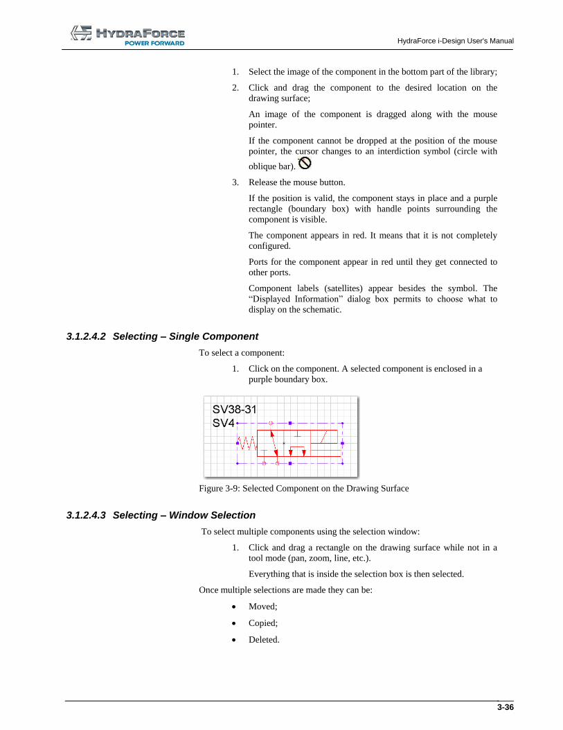
3.1.2.4.2 Selecting – Single Component
To select a component:
1. Click on the component. A selected component is enclosed in a
purple boundary box.
Figure 3-9: Selected Component on the Drawing Surface
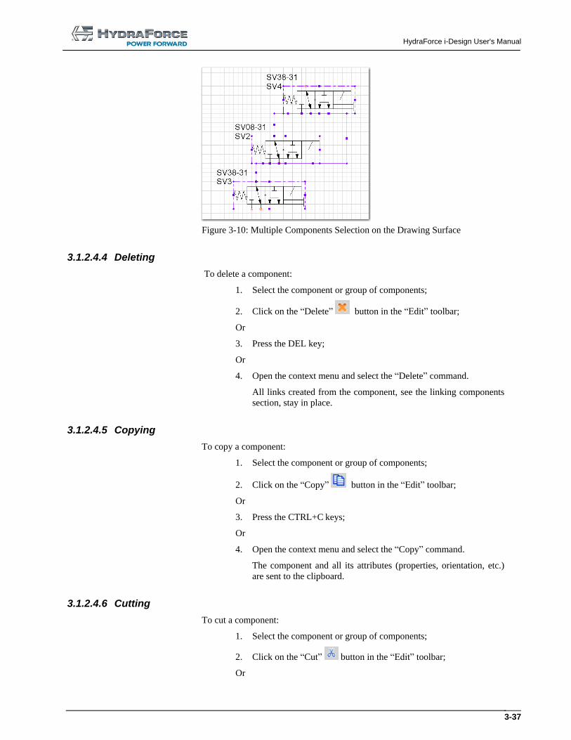
3.1.2.4.3 Selecting – Window Selection
To select multiple components using the selection window:
1. Click and drag a rectangle on the drawing surface while not in a
tool mode (pan, zoom, line, etc.).
Everything that is inside the selection box is then selected.
Once multiple selections are made they can be:
Moved;
Copied;
Deleted.
HydraForce i-Design User's Manual
3-37
Figure 3-10: Multiple Components Selection on the Drawing Surface
3.1.2.4.4 Deleting
To delete a component:
1. Select the component or group of components;
2. Click on the “Delete” button in the “Edit” toolbar;
Or
3. Press the DEL key;
Or
4. Open the context menu and select the “Delete” command.
All links created from the component, see the linking components
section, stay in place.
3.1.2.4.5 Copying
To copy a component:
1. Select the component or group of components;
2. Click on the “Copy” button in the “Edit” toolbar;
Or
3. Press the CTRL+C keys;
Or
4. Open the context menu and select the “Copy” command.
The component and all its attributes (properties, orientation, etc.)
are sent to the clipboard.
3.1.2.4.6 Cutting
To cut a component:
1. Select the component or group of components;
2. Click on the “Cut” button in the “Edit” toolbar;
Or
HydraForce i-Design User's Manual
3-38
3. Press the CTRL+X keys;
Or
4. Open the context menu and select the “Cut” command;
The component and all of its attributes (properties, orientation,
etc.) are sent to the clipboard. The component is removed from the
drawing surface.
3.1.2.4.7 Pasting
To paste a component:
1. Click on the drawing surface at the location where you want to
paste the component;
2. Click on the “Paste” button in the “Edit” toolbar;
Or
3. Press the CTRL+V keys;
Or
4. Open the context menu and select the “Paste” command.
Note: A component can only be pasted if it exists in the clipboard.
3.1.2.4.8 Rapid Copy/Paste
To accelerate the Copy/Paste function, press the CTRL key while moving a
component, this will automatically copy the component to the new position.
The mouse pointer changes to when the CTRL key is used.
3.1.2.4.9 Rotating
To rotate a component:
1. Select a component;
2. Use the clockwise rotation command in the “Layout” toolbar;
Or
3. Use the counter clockwise rotation command in the “Layout”
toolbar;
Or
4. Press on the CTRL+R or CTRL+H rotation right shortcut keys on
the keyboard;
Or
5. Press on the CTRL+L rotation left shortcut keys on the keyboard;
Or
6. Select the “Rotate Right” command from the context menu;
Or
HydraForce i-Design User's Manual
3-39
7. Select the “Rotate Left” command from the context menu.
The rotation of a component will rotate the symbol but not the satellite texts
associated to it.
3.1.2.4.10 Flipping
To flip a component:
1. Select a component;
2. Use the “Flip Horizontal” command on the “Layout” toolbar;
Or
3. Use the “Flip Vertical” command in the “Layout” toolbar;
Or
4. Press on the CTRL+T keys on the keyboard (Horizontal);
Or
5. Press on the CTRL+F keys on the keyboard (Vertical);
Or
6. Select the “Flip Horizontal” command from the context menu;
Or
7. Select the “Flip Vertical” command from the context menu.
The flipping of a component will flip the symbol but not the satellite texts
associated to it.
3.1.2.4.11 Moving
To move a component:
1. Drag and drop the component to a new position;
Or
2. Select the component and move it using the arrow keys.
The same rules apply if a component is dragged from the “Library”.
If links are attached to the component, the links remain attached when moving
it.
3.1.2.5 Context Menus
To access context menus, right-click with the mouse in one of the following
situations:
Mouse pointer is on Contents of the context menu
Component inserted in the drawing surface Undo (grayed if not available)
Redo (grayed if not available)
Cut
Copy
Paste (grayed if not available)
Delete
HydraForce i-Design User's Manual
3-40
Mouse pointer is on Contents of the context menu
Rotate Left
Rotate Right
Flip Horizontal
Flip Vertical
Properties
Help
Empty drawing space Paste (grayed if not available)
Help
3.1.2.6 Viewing Component Properties
To view component properties:
1. Double-click on the component;
2. Select the “Properties” command from the context menu of the
selected item.
See the “Component Properties” section of this manual for more details.
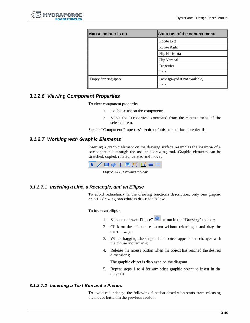
3.1.2.7 Working with Graphic Elements
Inserting a graphic element on the drawing surface resembles the insertion of a
component but through the use of a drawing tool. Graphic elements can be
stretched, copied, rotated, deleted and moved.
Figure 3-11: Drawing toolbar
3.1.2.7.1 Inserting a Line, a Rectangle, and an Ellipse
To avoid redundancy in the drawing functions description, only one graphic
object’s drawing procedure is described below.
To insert an ellipse:
1. Select the “Insert Ellipse” button in the “Drawing” toolbar;
2. Click on the left-mouse button without releasing it and drag the
cursor away;
3. While dragging, the shape of the object appears and changes with
the mouse movements;
4. Release the mouse button when the object has reached the desired
dimensions;
The graphic object is displayed on the diagram.
5. Repeat steps 1 to 4 for any other graphic object to insert in the
diagram.
3.1.2.7.2 Inserting a Text Box and a Picture
To avoid redundancy, the following function description starts from releasing
the mouse button in the previous section.
HydraForce i-Design User's Manual
3-41
To insert a text box:
1. Repeat steps 1 to 4 of the previous procedure, making sure the
“Insert Text” tool is selected from the “Drawing” toolbar;
2. In the entry box, type-in the text to include in the diagram.
To insert a picture:
1. Repeat steps 1 to 4 of the previous procedure making sure the
“Insert Image” tool is selected from the “Drawing” toolbar;
The “Open” dialog box pops up.
2. Select the image you wish to insert in the diagram;
Accepted formats are .JPG, .GIF and .BMP.
3. Click on Open.
The image appears on the diagram.
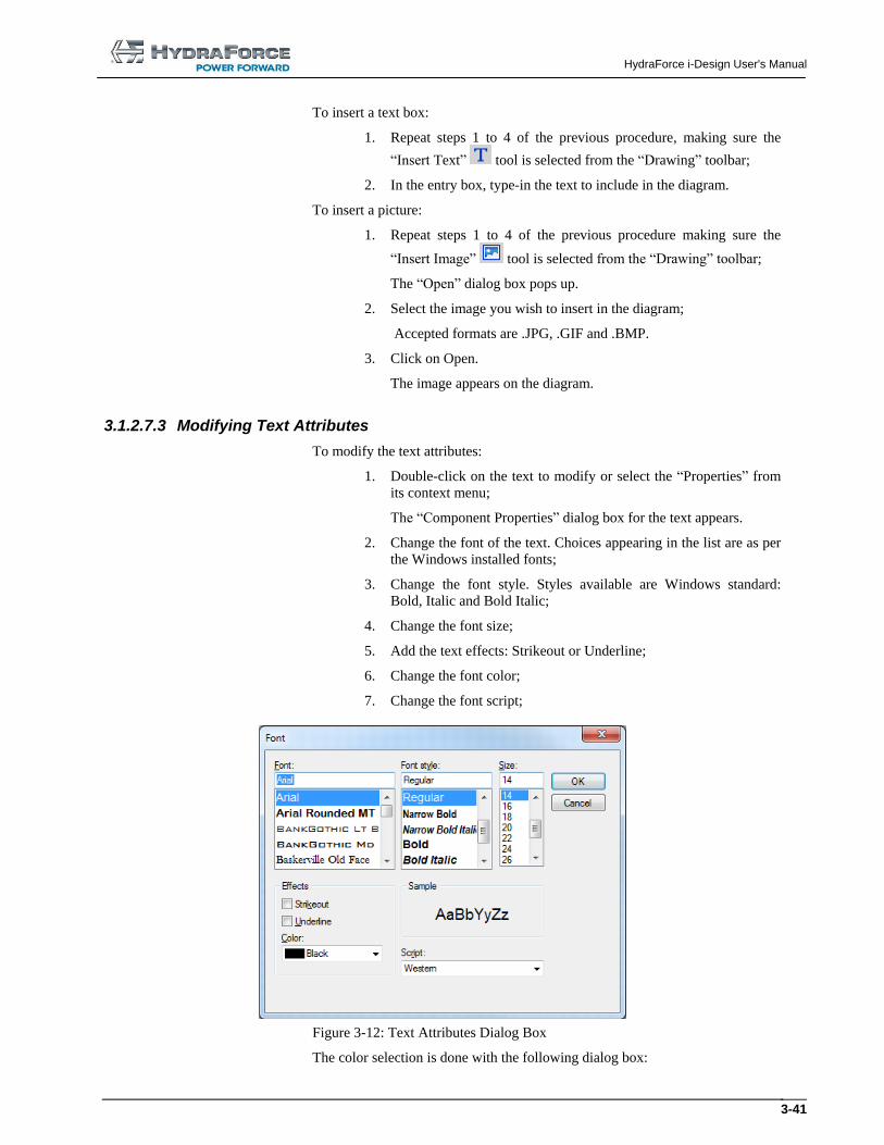
3.1.2.7.3 Modifying Text Attributes
To modify the text attributes:
1. Double-click on the text to modify or select the “Properties” from
its context menu;
The “Component Properties” dialog box for the text appears.
2. Change the font of the text. Choices appearing in the list are as per
the Windows installed fonts;
3. Change the font style. Styles available are Windows standard:
Bold, Italic and Bold Italic;
4. Change the font size;
5. Add the text effects: Strikeout or Underline;
6. Change the font color;
7. Change the font script;
Figure 3-12: Text Attributes Dialog Box
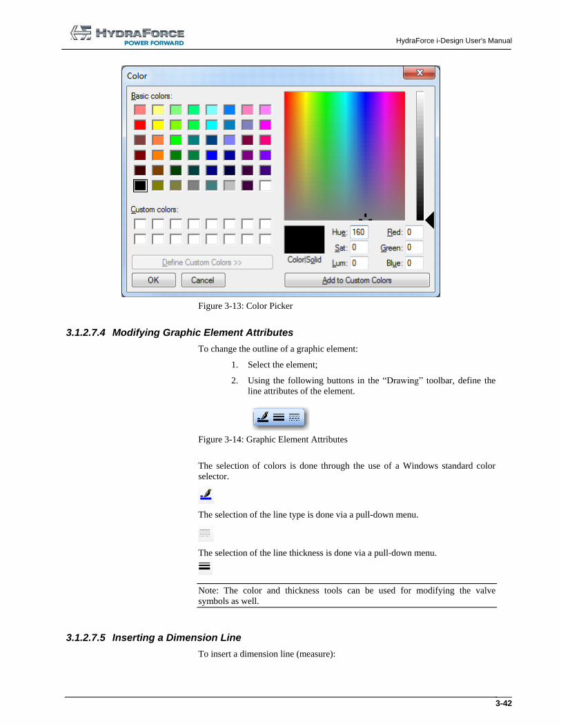
The color selection is done with the following dialog box:
HydraForce i-Design User's Manual
3-42
Figure 3-13: Color Picker
3.1.2.7.4 Modifying Graphic Element Attributes
To change the outline of a graphic element:
1. Select the element;
2. Using the following buttons in the “Drawing” toolbar, define the
line attributes of the element.
Figure 3-14: Graphic Element Attributes
The selection of colors is done through the use of a Windows standard color
selector.
The selection of the line type is done via a pull-down menu.
The selection of the line thickness is done via a pull-down menu.
Note: The color and thickness tools can be used for modifying the valve
symbols as well.
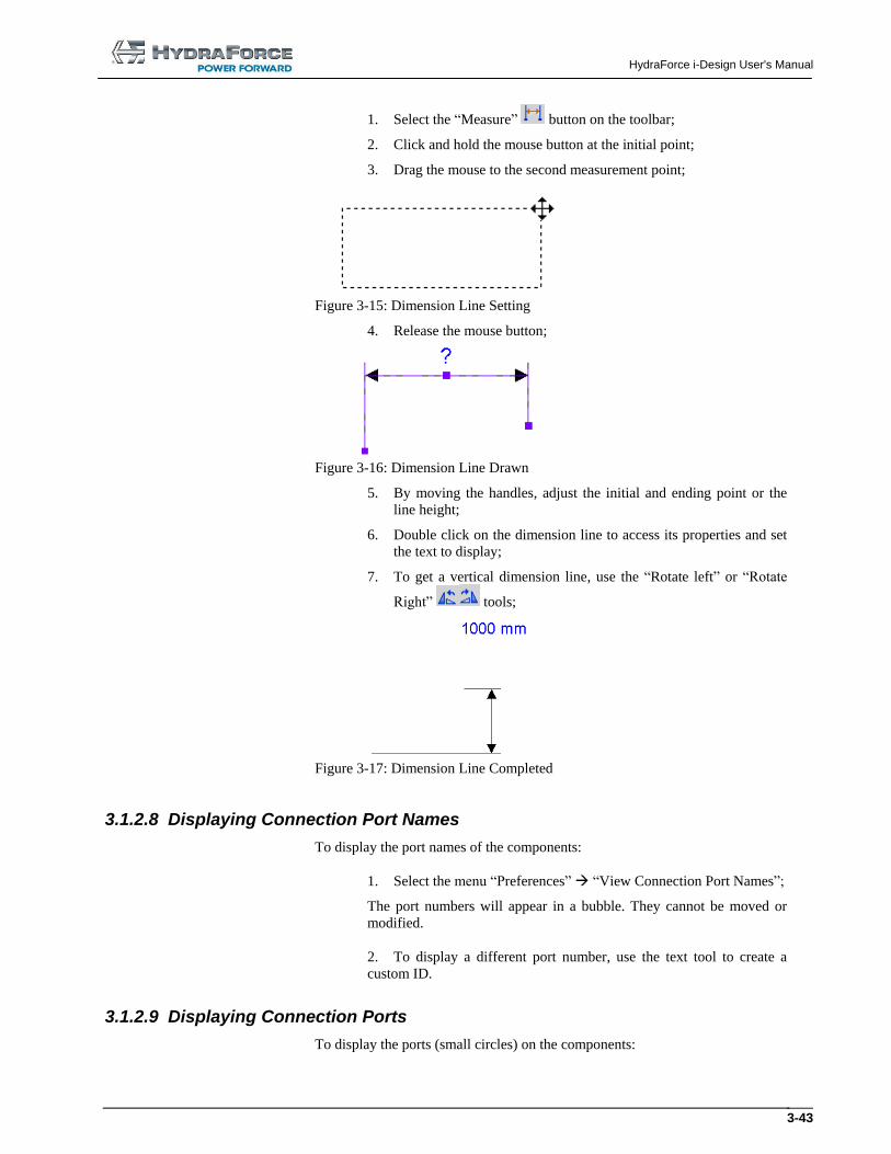
3.1.2.7.5 Inserting a Dimension Line
To insert a dimension line (measure):
HydraForce i-Design User's Manual
3-43
1. Select the “Measure” button on the toolbar;
2. Click and hold the mouse button at the initial point;
3. Drag the mouse to the second measurement point;
Figure 3-15: Dimension Line Setting
4. Release the mouse button;
Figure 3-16: Dimension Line Drawn
5. By moving the handles, adjust the initial and ending point or the
line height;
6. Double click on the dimension line to access its properties and set
the text to display;
7. To get a vertical dimension line, use the “Rotate left” or “Rotate
Right” tools;
Figure 3-17: Dimension Line Completed
3.1.2.8 Displaying Connection Port Names
To display the port names of the components:
1. Select the menu “Preferences” “View Connection Port Names”;
The port numbers will appear in a bubble. They cannot be moved or
modified.
2. To display a different port number, use the text tool to create a
custom ID.
3.1.2.9 Displaying Connection Ports
To display the ports (small circles) on the components:
HydraForce i-Design User's Manual
3-44
1. Select the menu “Preferences” “View Connection Ports”.
The ports will appear or disappear depending on their current state.
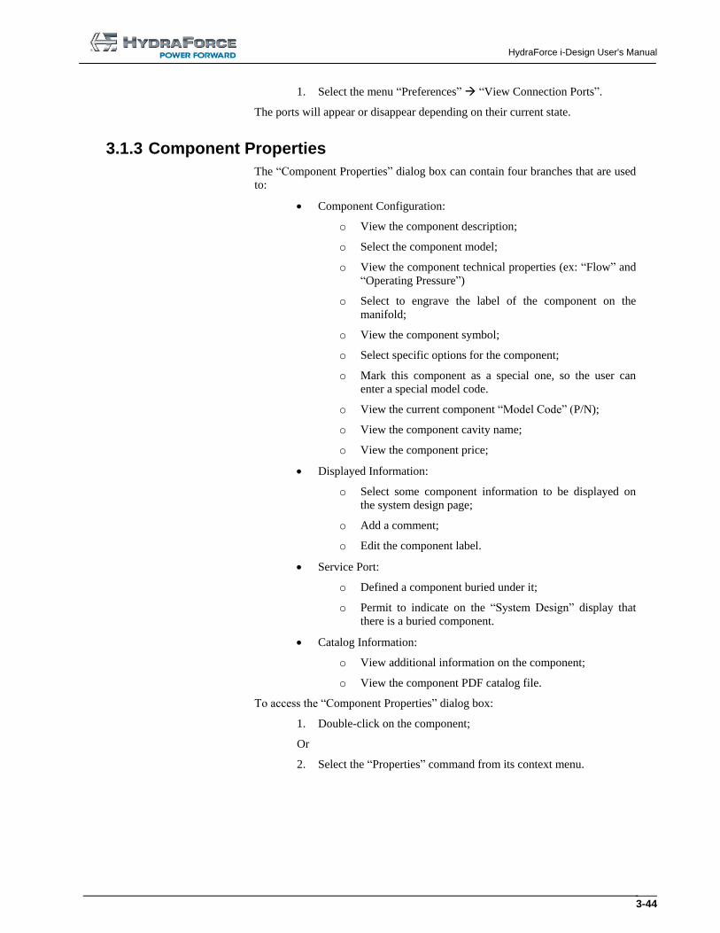
3.1.3 Component Properties
The “Component Properties” dialog box can contain four branches that are used
to:
Component Configuration:
o View the component description;
o Select the component model;
o View the component technical properties (ex: “Flow” and
“Operating Pressure”)
o Select to engrave the label of the component on the
manifold;
o View the component symbol;
o Select specific options for the component;
o Mark this component as a special one, so the user can
enter a special model code.
o View the current component “Model Code” (P/N);
o View the component cavity name;
o View the component price;
Displayed Information:
o Select some component information to be displayed on
the system design page;
o Add a comment;
o Edit the component label.
Service Port:
o Defined a component buried under it;
o Permit to indicate on the “System Design” display that
there is a buried component.
Catalog Information:
o View additional information on the component;
o View the component PDF catalog file.
To access the “Component Properties” dialog box:
1. Double-click on the component;
Or
2. Select the “Properties” command from its context menu.
HydraForce i-Design User's Manual
3-45
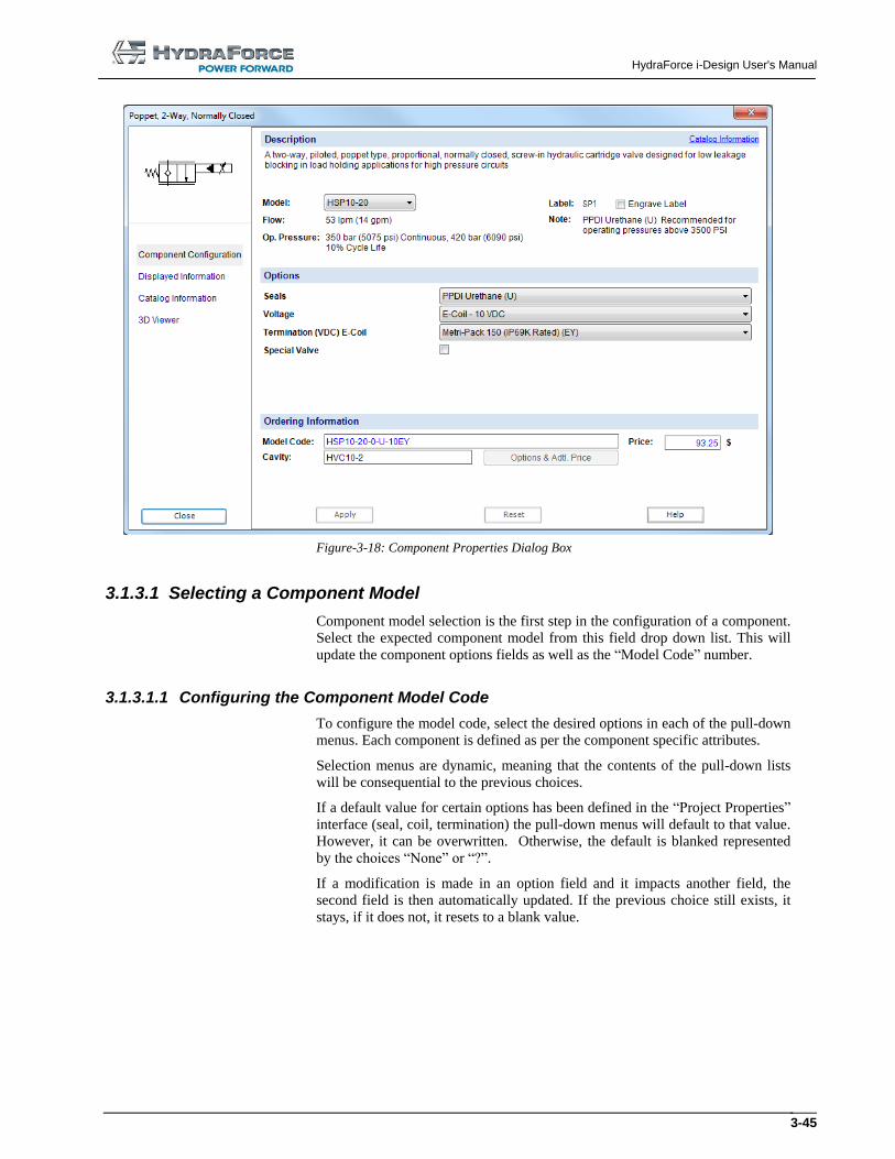
Figure-3-18: Component Properties Dialog Box
3.1.3.1 Selecting a Component Model
Component model selection is the first step in the configuration of a component.
Select the expected component model from this field drop down list. This will
update the component options fields as well as the “Model Code” number.
3.1.3.1.1 Configuring the Component Model Code
To configure the model code, select the desired options in each of the pull-down
menus. Each component is defined as per the component specific attributes.
Selection menus are dynamic, meaning that the contents of the pull-down lists
will be consequential to the previous choices.
If a default value for certain options has been defined in the “Project Properties”
interface (seal, coil, termination) the pull-down menus will default to that value.
However, it can be overwritten. Otherwise, the default is blanked represented
by the choices “None” or “?”.
If a modification is made in an option field and it impacts another field, the
second field is then automatically updated. If the previous choice still exists, it
stays, if it does not, it resets to a blank value.
HydraForce i-Design User's Manual
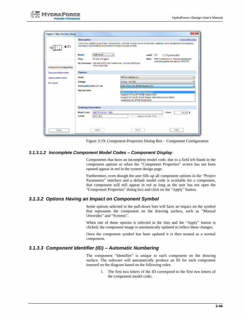
3-46
Figure 3-19: Component Properties Dialog Box – Component Configuration
3.1.3.1.2 Incomplete Component Model Codes – Component Display
Components that have an incomplete model code, due to a field left blank in the
component options or when the “Component Properties” screen has not been
opened appear in red in the system design page.
Furthermore, even though the user fills up all component options in the “Project
Parameters” interface and a default model code is available for a component,
that component will still appear in red as long as the user has not open the
“Component Properties” dialog box and click on the “Apply” button.
3.1.3.2 Options Having an Impact on Component Symbol
Some options selected in the pull-down lists will have an impact on the symbol
that represents the component on the drawing surface, such as “Manual
Overrides” and “Screens”.
When one of these options is selected in the lists and the “Apply” button is
clicked, the component image is automatically updated to reflect these changes.
Once the component symbol has been updated it is then treated as a normal
component.
3.1.3.3 Component Identifier (ID) – Automatic Numbering
The component “Identifier” is unique to each component on the drawing
surface. The software will automatically produce an ID for each component
inserted on the diagram based on the following rules:
1. The first two letters of the ID correspond to the first two letters of
the component model code;
HydraForce i-Design User's Manual
3-47
2. The following two digits are a sequential number in function of the
first two digits. Example: the first valve will be CV01, the second
CV02 and so on.
Note: There is no check for “Component ID” uniqueness. The “Component
Label” can be edited in the “Displayed Information” dialog box, but not the
“Component ID”. The “Component ID” is a sequential number and will always
take the value of a free number or increment the last available one. For example:
There is SV1, SV2, SV4 and SV3 was deleted. The new inserted component will
have the “Component ID” SV03. The next component inserted will take the ID
SV5.
3.1.3.4 Component Cavity
For each component, a cavity is identified. This cavity is defined as per the
specific component options found in the manufacturer’s catalog. Furthermore,
the corresponding cavity will appear in the “Component Properties”
“Component Configuration” dialog box.
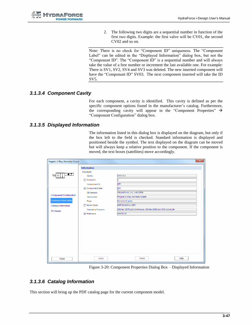
3.1.3.5 Displayed Information
The information listed in this dialog box is displayed on the diagram, but only if
the box left to the field is checked. Standard information is displayed and
positioned beside the symbol. The text displayed on the diagram can be moved
but will always keep a relative position to the component. If the component is
moved, the text boxes (satellites) move accordingly.
Figure 3-20: Component Properties Dialog Box – Displayed Information
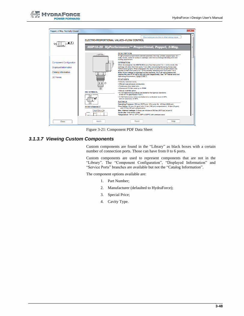
3.1.3.6 Catalog Information
This section will bring up the PDF catalog page for the current component model.
HydraForce i-Design User's Manual
3-48
Figure 3-21: Component PDF Data Sheet
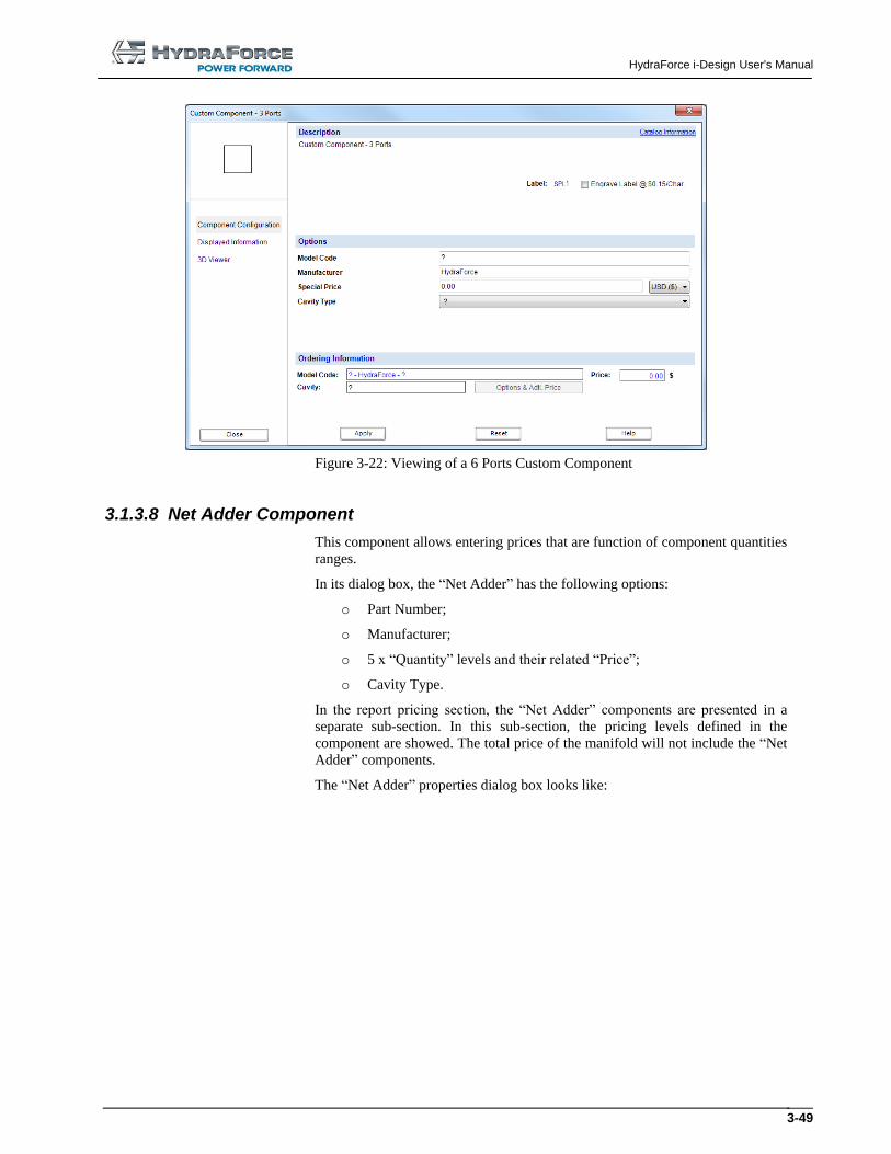
3.1.3.7 Viewing Custom Components
Custom components are found in the “Library” as black boxes with a certain
number of connection ports. Those can have from 0 to 6 ports.
Custom components are used to represent components that are not in the
“Library”. The “Component Configuration”, “Displayed Information” and
“Service Ports” branches are available but not the “Catalog Information”.
The component options available are:
1. Part Number;
2. Manufacturer (defaulted to HydraForce);
3. Special Price;
4. Cavity Type.
HydraForce i-Design User's Manual
3-49
Figure 3-22: Viewing of a 6 Ports Custom Component
3.1.3.8 Net Adder Component
This component allows entering prices that are function of component quantities
ranges.
In its dialog box, the “Net Adder” has the following options:
o Part Number;
o Manufacturer;
o 5 x “Quantity” levels and their related “Price”;
o Cavity Type.
In the report pricing section, the “Net Adder” components are presented in a
separate sub-section. In this sub-section, the pricing levels defined in the
component are showed. The total price of the manifold will not include the “Net
Adder” components.
The “Net Adder” properties dialog box looks like:

HydraForce i-Design User's Manual
3-50
Figure 3-23: Net Adder Component (Component Configuration)
HydraForce i-Design User's Manual
3-51
3.1.4 Creating a Design
3.1.4.1 Connecting Components
To connect components:
1. Click on one of the symbol connection ports to define the starting
point. The connection ports appear in red when a component is
inserted onto the drawing surface and still not connected;
The mouse pointer takes the shape of a cross.
2. Each click, other than on another connection port, defines a new
elbow in the link;
3. Click on another port to create a connection. The link is established
between the two components;
Or
4. Double clicked on the drawing where there is no connection port.
The link will terminate at that point with a connection port at its
end.
The mouse pointer reverts to its initial shape once the link is
finished, as described in steps 3 and 4.
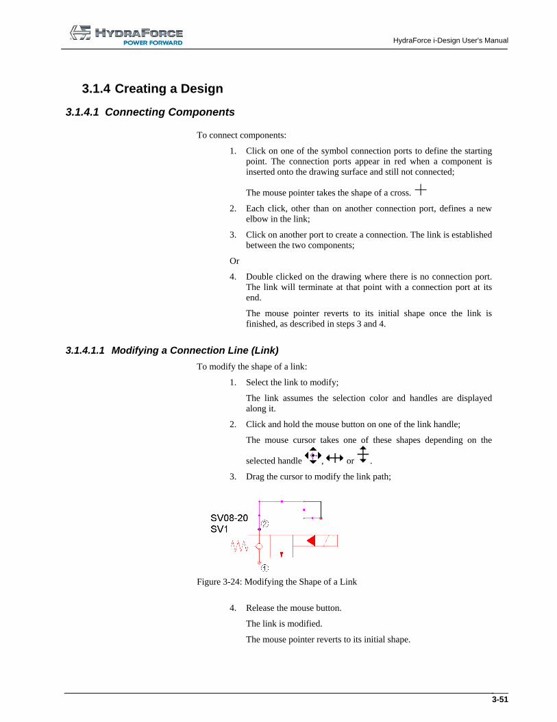
3.1.4.1.1 Modifying a Connection Line (Link)
To modify the shape of a link:
1. Select the link to modify;
The link assumes the selection color and handles are displayed
along it.
2. Click and hold the mouse button on one of the link handle;
The mouse cursor takes one of these shapes depending on the
selected handle , or .
3. Drag the cursor to modify the link path;
Figure 3-24: Modifying the Shape of a Link
4. Release the mouse button.
The link is modified.
The mouse pointer reverts to its initial shape.
HydraForce i-Design User's Manual
3-52
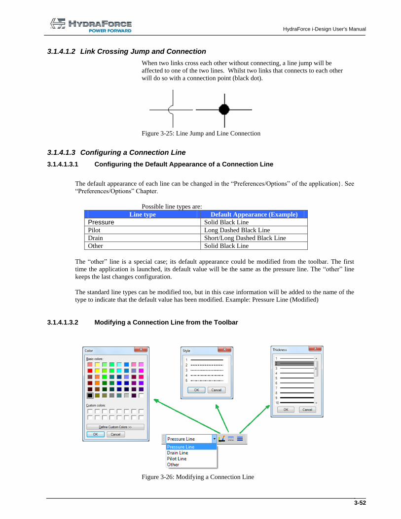
3.1.4.1.2 Link Crossing Jump and Connection
When two links cross each other without connecting, a line jump will be
affected to one of the two lines. Whilst two links that connects to each other
will do so with a connection point (black dot).
Figure 3-25: Line Jump and Line Connection
3.1.4.1.3 Configuring a Connection Line
3.1.4.1.3.1 Configuring the Default Appearance of a Connection Line
The default appearance of each line can be changed in the “Preferences/Options” of the application}. See
“Preferences/Options” Chapter.
Possible line types are:
Line type Default Appearance (Example)
Pressure Solid Black Line
Pilot Long Dashed Black Line
Drain Short/Long Dashed Black Line
Other Solid Black Line
The “other” line is a special case; its default appearance could be modified from the toolbar. The first
time the application is launched, its default value will be the same as the pressure line. The “other” line
keeps the last changes configuration.
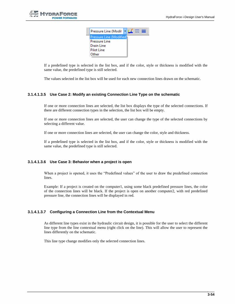
The standard line types can be modified too, but in this case information will be added to the name of the
type to indicate that the default value has been modified. Example: Pressure Line (Modified)
3.1.4.1.3.2 Modifying a Connection Line from the Toolbar
Figure 3-26: Modifying a Connection Line
HydraForce i-Design User's Manual
3-53
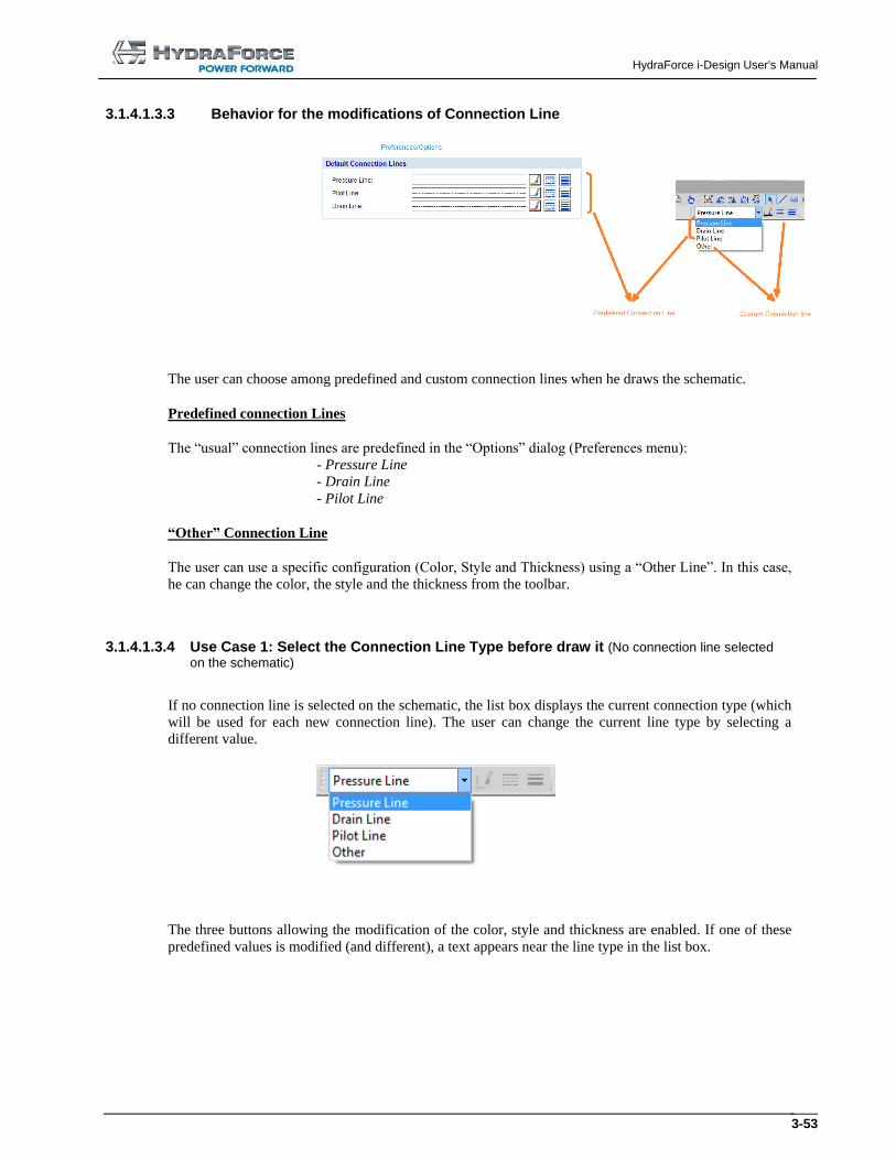
3.1.4.1.3.3 Behavior for the modifications of Connection Line
The user can choose among predefined and custom connection lines when he draws the schematic.
Predefined connection Lines
The “usual” connection lines are predefined in the “Options” dialog (Preferences menu):
- Pressure Line
- Drain Line
- Pilot Line
“Other” Connection Line
The user can use a specific configuration (Color, Style and Thickness) using a “Other Line”. In this case,
he can change the color, the style and the thickness from the toolbar.
3.1.4.1.3.4 Use Case 1: Select the Connection Line Type before draw it (No connection line selected
on the schematic)
If no connection line is selected on the schematic, the list box displays the current connection type (which
will be used for each new connection line). The user can change the current line type by selecting a
different value.
The three buttons allowing the modification of the color, style and thickness are enabled. If one of these
predefined values is modified (and different), a text appears near the line type in the list box.
HydraForce i-Design User's Manual
3-54
If a predefined type is selected in the list box, and if the color, style or thickness is modified with the
same value, the predefined type is still selected.
The values selected in the list box will be used for each new connection lines drawn on the schematic.
3.1.4.1.3.5 Use Case 2: Modify an existing Connection Line Type on the schematic
If one or more connection lines are selected, the list box displays the type of the selected connections. If
there are different connection types in the selection, the list box will be empty.
If one or more connection lines are selected, the user can change the type of the selected connections by
selecting a different value.
If one or more connection lines are selected, the user can change the color, style and thickness.
If a predefined type is selected in the list box, and if the color, style or thickness is modified with the
same value, the predefined type is still selected.
3.1.4.1.3.6 Use Case 3: Behavior when a project is open
When a project is opened, it uses the “Predefined values” of the user to draw the predefined connection
lines.
Example: If a project is created on the computer1, using some black predefined pressure lines, the color
of the connection lines will be black. If the project is open on another computer2, with red predefined
pressure line, the connection lines will be displayed in red.
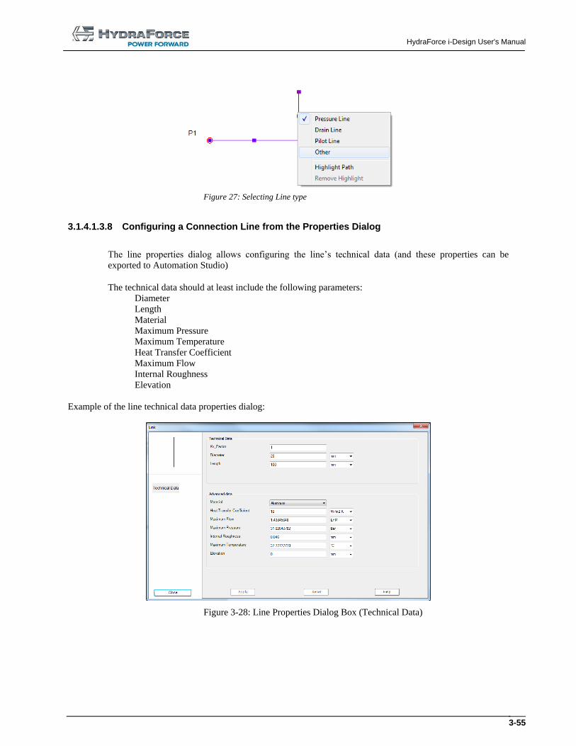
3.1.4.1.3.7 Configuring a Connection Line from the Contextual Menu
As different line types exist in the hydraulic circuit design, it is possible for the user to select the different
line type from the line contextual menu (right click on the line). This will allow the user to represent the
lines differently on the schematic.
This line type change modifies only the selected connection lines.
HydraForce i-Design User's Manual
3-55
Figure 27: Selecting Line type
3.1.4.1.3.8 Configuring a Connection Line from the Properties Dialog
The line properties dialog allows configuring the line’s technical data (and these properties can be
exported to Automation Studio)
The technical data should at least include the following parameters:
Diameter
Length
Material
Maximum Pressure
Maximum Temperature
Heat Transfer Coefficient
Maximum Flow
Internal Roughness
Elevation
Example of the line technical data properties dialog:
Figure 3-28: Line Properties Dialog Box (Technical Data)
HydraForce i-Design User's Manual
3-56
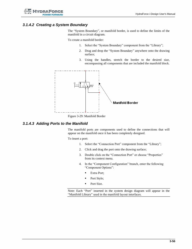
3.1.4.2 Creating a System Boundary
The “System Boundary”, or manifold border, is used to define the limits of the
manifold in a circuit diagram.
To create a manifold border:
1. Select the “System Boundary” component from the “Library”;
2. Drag and drop the “System Boundary” anywhere onto the drawing
surface;
3. Using the handles, stretch the border to the desired size,
encompassing all components that are included the manifold block.
Figure 3-29: Manifold Border
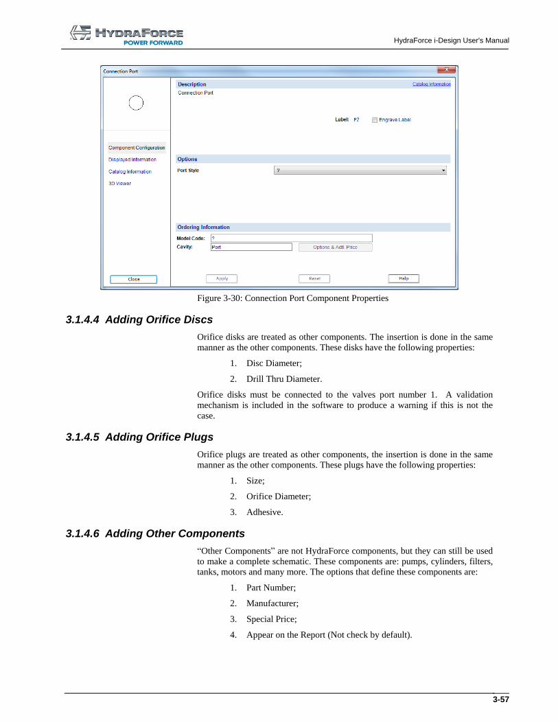
3.1.4.3 Adding Ports to the Manifold
The manifold ports are components used to define the connections that will
appear on the manifold once it has been completely designed.
To insert a port:
1. Select the “Connection Port” component from the “Library”;
2. Click and drag the port onto the drawing surface;
3. Double click on the “Connection Port” or choose “Properties”
from its context menu.
4. In the “Component Configuration” branch, enter the following
“Component Options”:
Extra Port;
Port Style;
Port Size.
Note: Each “Port” inserted in the system design diagram will appear in the
“Manifold Library” used in the manifold layout interfaces.
HydraForce i-Design User's Manual
3-57
Figure 3-30: Connection Port Component Properties
3.1.4.4 Adding Orifice Discs
Orifice disks are treated as other components. The insertion is done in the same
manner as the other components. These disks have the following properties:
1. Disc Diameter;
2. Drill Thru Diameter.
Orifice disks must be connected to the valves port number 1. A validation
mechanism is included in the software to produce a warning if this is not the
case.
3.1.4.5 Adding Orifice Plugs
Orifice plugs are treated as other components, the insertion is done in the same
manner as the other components. These plugs have the following properties:
1. Size;
2. Orifice Diameter;
3. Adhesive.
3.1.4.6 Adding Other Components
“Other Components” are not HydraForce components, but they can still be used
to make a complete schematic. These components are: pumps, cylinders, filters,
tanks, motors and many more. The options that define these components are:
1. Part Number;
2. Manufacturer;
3. Special Price;
4. Appear on the Report (Not check by default).
HydraForce i-Design User's Manual
3-58
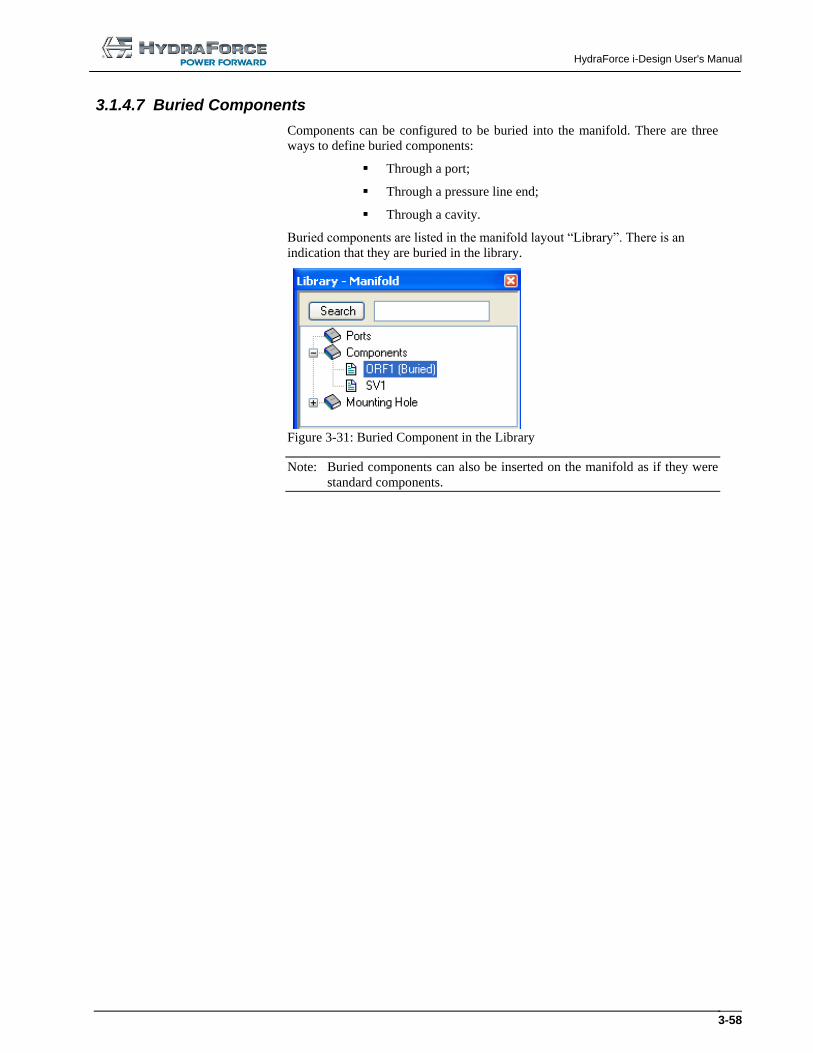
3.1.4.7 Buried Components
Components can be configured to be buried into the manifold. There are three
ways to define buried components:
Through a port;
Through a pressure line end;
Through a cavity.
Buried components are listed in the manifold layout “Library”. There is an
indication that they are buried in the library.
Figure 3-31: Buried Component in the Library
Note: Buried components can also be inserted on the manifold as if they were
standard components.
HydraForce i-Design User's Manual
3-59
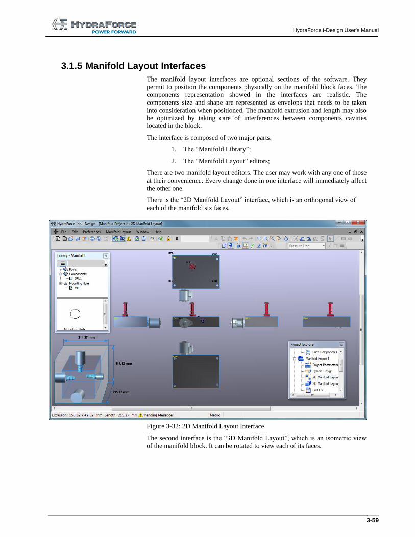
3.1.5 Manifold Layout Interfaces
The manifold layout interfaces are optional sections of the software. They
permit to position the components physically on the manifold block faces. The
components representation showed in the interfaces are realistic. The
components size and shape are represented as envelops that needs to be taken
into consideration when positioned. The manifold extrusion and length may also
be optimized by taking care of interferences between components cavities
located in the block.
The interface is composed of two major parts:
1. The “Manifold Library”;
2. The “Manifold Layout” editors;
There are two manifold layout editors. The user may work with any one of those
at their convenience. Every change done in one interface will immediately affect
the other one.
There is the “2D Manifold Layout” interface, which is an orthogonal view of
each of the manifold six faces.
Figure 3-32: 2D Manifold Layout Interface
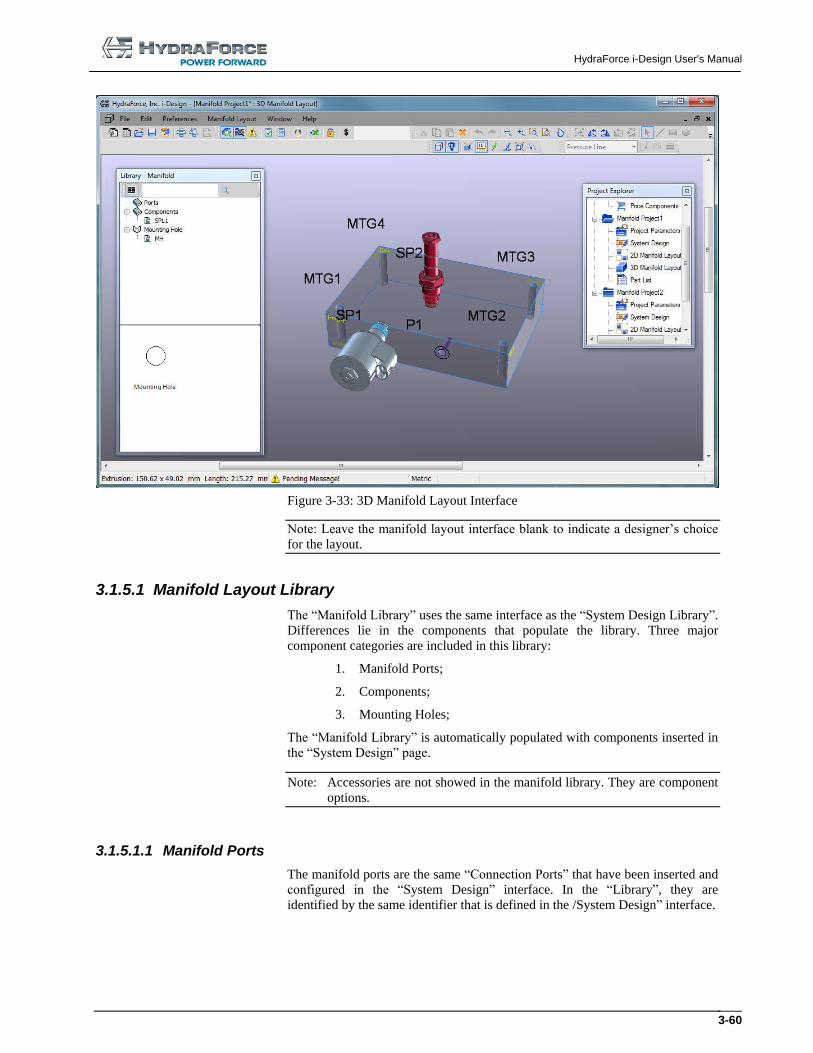
The second interface is the “3D Manifold Layout”, which is an isometric view
of the manifold block. It can be rotated to view each of its faces.
HydraForce i-Design User's Manual
3-60
Figure 3-33: 3D Manifold Layout Interface
Note: Leave the manifold layout interface blank to indicate a designer’s choice
for the layout.
3.1.5.1 Manifold Layout Library
The “Manifold Library” uses the same interface as the “System Design Library”.
Differences lie in the components that populate the library. Three major
component categories are included in this library:
1. Manifold Ports;
2. Components;
3. Mounting Holes;
The “Manifold Library” is automatically populated with components inserted in
the “System Design” page.
Note: Accessories are not showed in the manifold library. They are component
options.
3.1.5.1.1 Manifold Ports
The manifold ports are the same “Connection Ports” that have been inserted and
configured in the “System Design” interface. In the “Library”, they are
identified by the same identifier that is defined in the /System Design” interface.
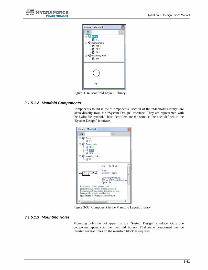
HydraForce i-Design User's Manual
3-61
Figure 3-34: Manifold Layout Library
3.1.5.1.2 Manifold Components
Components found in the “Components” section of the “Manifold Library” are
taken directly from the “System Design” interface. They are represented with
the hydraulic symbol. Their identifiers are the same as the ones defined in the
“System Design” interface.
Figure 3-35: Component in the Manifold Layout Library
3.1.5.1.3 Mounting Holes
Mounting holes do not appear in the “System Design” interface. Only one
component appears in the manifold library. That same component can be
inserted several times on the manifold block as required.
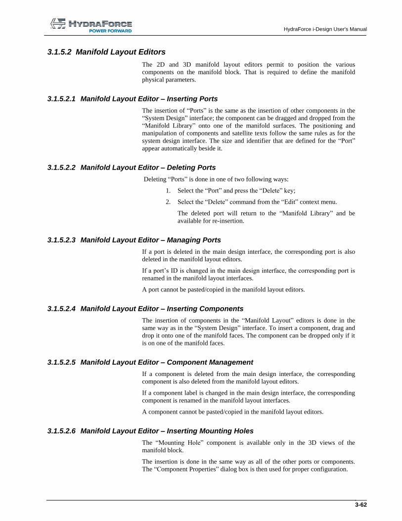
HydraForce i-Design User's Manual
3-62
3.1.5.2 Manifold Layout Editors
The 2D and 3D manifold layout editors permit to position the various
components on the manifold block. That is required to define the manifold
physical parameters.
3.1.5.2.1 Manifold Layout Editor – Inserting Ports
The insertion of “Ports” is the same as the insertion of other components in the
“System Design” interface; the component can be dragged and dropped from the
“Manifold Library” onto one of the manifold surfaces. The positioning and
manipulation of components and satellite texts follow the same rules as for the
system design interface. The size and identifier that are defined for the “Port”
appear automatically beside it.
3.1.5.2.2 Manifold Layout Editor – Deleting Ports
Deleting “Ports” is done in one of two following ways:
1. Select the “Port” and press the “Delete” key;
2. Select the “Delete” command from the “Edit” context menu.
The deleted port will return to the “Manifold Library” and be
available for re-insertion.
3.1.5.2.3 Manifold Layout Editor – Managing Ports
If a port is deleted in the main design interface, the corresponding port is also
deleted in the manifold layout editors.
If a port’s ID is changed in the main design interface, the corresponding port is
renamed in the manifold layout interfaces.
A port cannot be pasted/copied in the manifold layout editors.
3.1.5.2.4 Manifold Layout Editor – Inserting Components
The insertion of components in the “Manifold Layout” editors is done in the
same way as in the “System Design” interface. To insert a component, drag and
drop it onto one of the manifold faces. The component can be dropped only if it
is on one of the manifold faces.
3.1.5.2.5 Manifold Layout Editor – Component Management
If a component is deleted from the main design interface, the corresponding
component is also deleted from the manifold layout editors.
If a component label is changed in the main design interface, the corresponding
component is renamed in the manifold layout interfaces.
A component cannot be pasted/copied in the manifold layout editors.
3.1.5.2.6 Manifold Layout Editor – Inserting Mounting Holes
The “Mounting Hole” component is available only in the 3D views of the
manifold block.
The insertion is done in the same way as all of the other ports or components.
The “Component Properties” dialog box is then used for proper configuration.
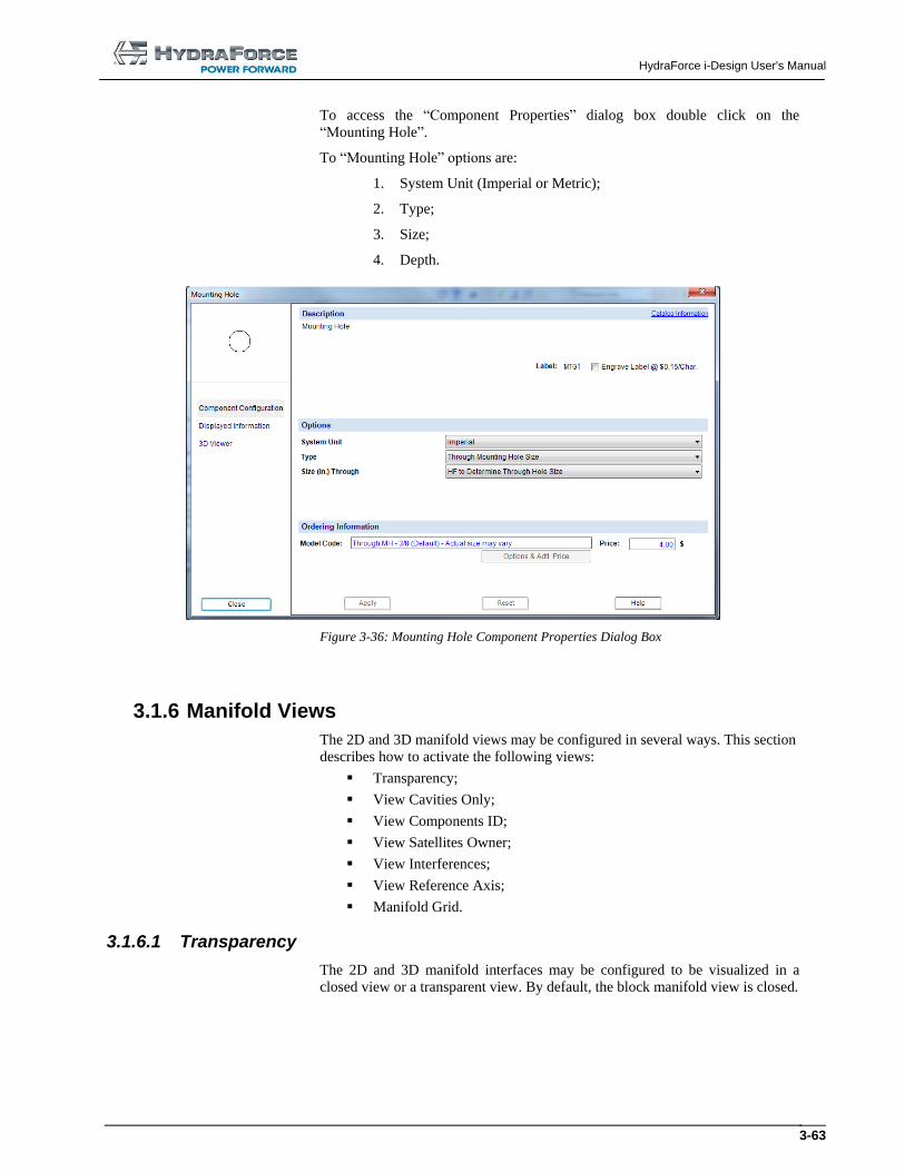
HydraForce i-Design User's Manual
3-63
To access the “Component Properties” dialog box double click on the
“Mounting Hole”.
To “Mounting Hole” options are:
1. System Unit (Imperial or Metric);
2. Type;
3. Size;
4. Depth.
Figure 3-36: Mounting Hole Component Properties Dialog Box
3.1.6 Manifold Views
The 2D and 3D manifold views may be configured in several ways. This section
describes how to activate the following views:
Transparency;
View Cavities Only;
View Components ID;
View Satellites Owner;
View Interferences;
View Reference Axis;
Manifold Grid.
3.1.6.1 Transparency
The 2D and 3D manifold interfaces may be configured to be visualized in a
closed view or a transparent view. By default, the block manifold view is closed.
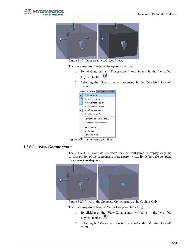
HydraForce i-Design User's Manual
3-64
Figure 3-37: Transparent vs. Closed Views
There is 2 ways to change the transparency setting:
1. By clicking on the “Transparency” tool button in the “Manifold
Layout” toolbar.
2. Selecting the “Transparency” command in the “Manifold Layout”
menu.
Figure 3-38: Transparency Option
3.1.6.2 View Components
The 2D and 3D manifold interfaces may be configured to display only the
cavities portion of the components in transparent view. By default, the complete
components are displayed.
Figure 3-39: View of the Complete Components vs. the Cavities Only
There is 2 ways to change the “View Components” setting:
1. By clicking on the “View Components” tool button in the “Manifold
Layout” toolbar.
2. Selecting the “View Components” command in the “Manifold Layout”
menu.
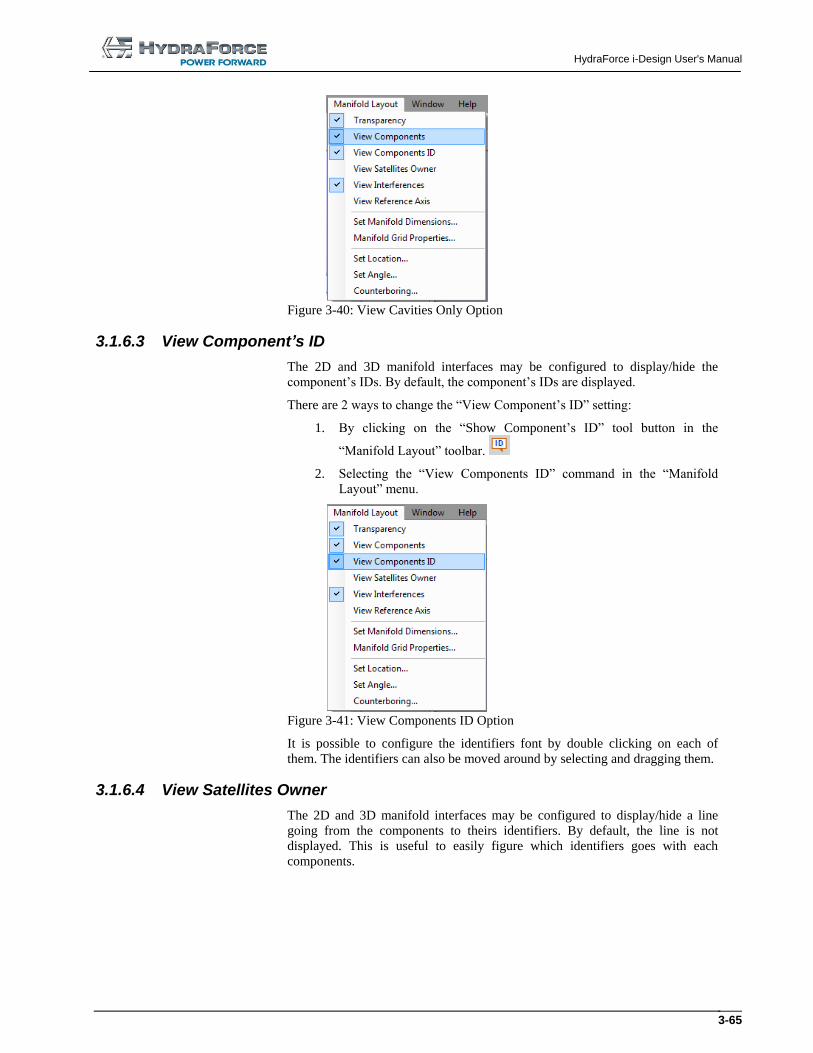
HydraForce i-Design User's Manual
3-65
Figure 3-40: View Cavities Only Option
3.1.6.3 View Component’s ID
The 2D and 3D manifold interfaces may be configured to display/hide the
component’s IDs. By default, the component’s IDs are displayed.
There are 2 ways to change the “View Component’s ID” setting:
1. By clicking on the “Show Component’s ID” tool button in the
“Manifold Layout” toolbar.
2. Selecting the “View Components ID” command in the “Manifold
Layout” menu.
Figure 3-41: View Components ID Option
It is possible to configure the identifiers font by double clicking on each of
them. The identifiers can also be moved around by selecting and dragging them.
3.1.6.4 View Satellites Owner
The 2D and 3D manifold interfaces may be configured to display/hide a line
going from the components to theirs identifiers. By default, the line is not
displayed. This is useful to easily figure which identifiers goes with each
components.
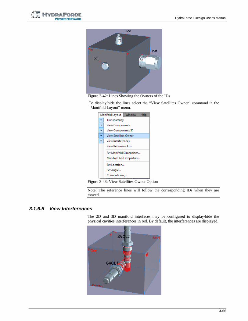
HydraForce i-Design User's Manual
3-66
Figure 3-42: Lines Showing the Owners of the IDs
To display/hide the lines select the “View Satellites Owner” command in the
“Manifold Layout” menu.
Figure 3-43: View Satellites Owner Option
Note: The reference lines will follow the corresponding IDs when they are
moved.
3.1.6.5 View Interferences
The 2D and 3D manifold interfaces may be configured to display/hide the
physical cavities interferences in red. By default, the interferences are displayed.
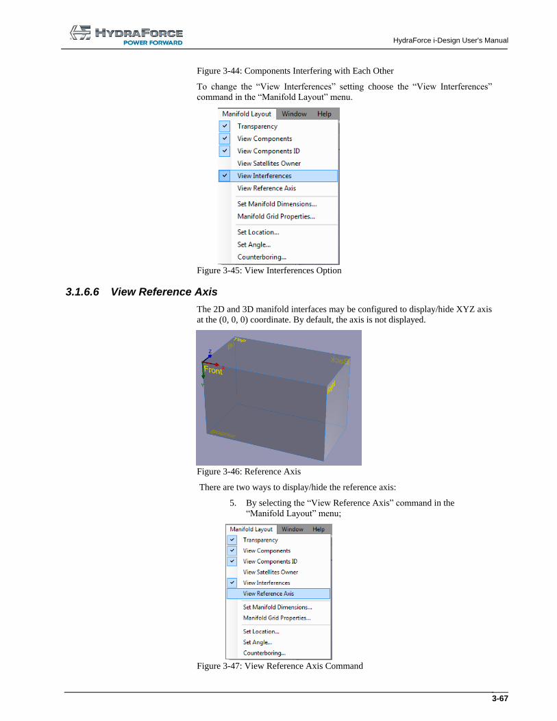
HydraForce i-Design User's Manual
3-67
Figure 3-44: Components Interfering with Each Other
To change the “View Interferences” setting choose the “View Interferences”
command in the “Manifold Layout” menu.
Figure 3-45: View Interferences Option
3.1.6.6 View Reference Axis
The 2D and 3D manifold interfaces may be configured to display/hide XYZ axis
at the (0, 0, 0) coordinate. By default, the axis is not displayed.
Figure 3-46: Reference Axis
There are two ways to display/hide the reference axis:
5. By selecting the “View Reference Axis” command in the
“Manifold Layout” menu;
Figure 3-47: View Reference Axis Command
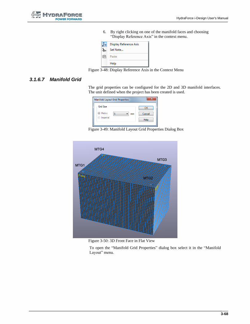
HydraForce i-Design User's Manual
3-68
6. By right clicking on one of the manifold faces and choosing
“Display Reference Axis” in the context menu.
Figure 3-48: Display Reference Axis in the Context Menu
3.1.6.7 Manifold Grid
The grid properties can be configured for the 2D and 3D manifold interfaces.
The unit defined when the project has been created is used.
Figure 3-49: Manifold Layout Grid Properties Dialog Box
Figure 3-50: 3D Front Face in Flat View
To open the “Manifold Grid Properties” dialog box select it in the “Manifold
Layout” menu.
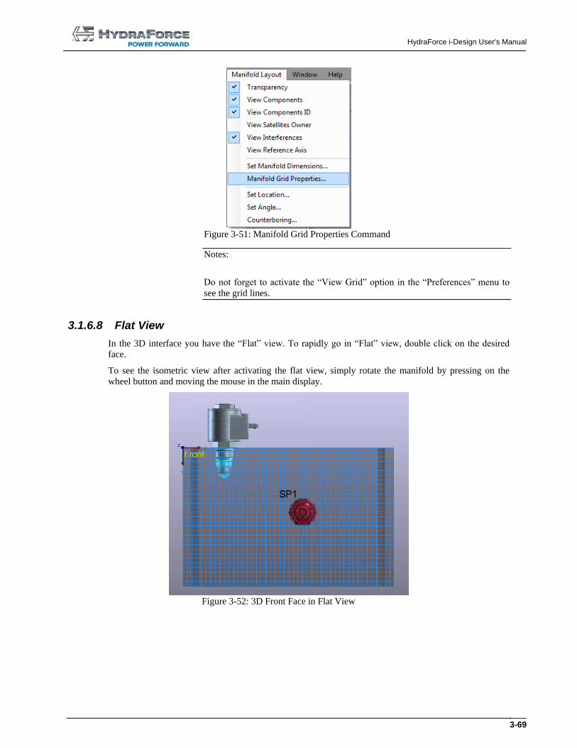
HydraForce i-Design User's Manual
3-69
Figure 3-51: Manifold Grid Properties Command
Notes:
Do not forget to activate the “View Grid” option in the “Preferences” menu to
see the grid lines.
3.1.6.8 Flat View
In the 3D interface you have the “Flat” view. To rapidly go in “Flat” view, double click on the desired
face.
To see the isometric view after activating the flat view, simply rotate the manifold by pressing on the
wheel button and moving the mouse in the main display.
Figure 3-52: 3D Front Face in Flat View
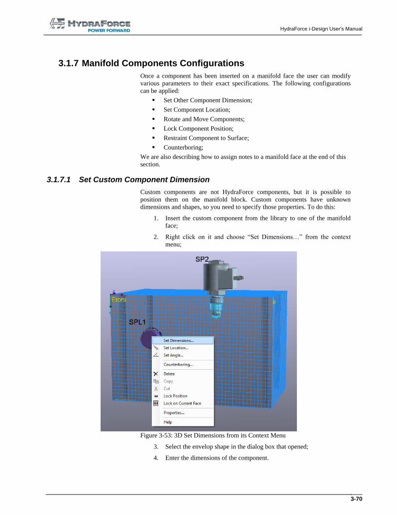
HydraForce i-Design User's Manual
3-70
3.1.7 Manifold Components Configurations
Once a component has been inserted on a manifold face the user can modify
various parameters to their exact specifications. The following configurations
can be applied:
Set Other Component Dimension;
Set Component Location;
Rotate and Move Components;
Lock Component Position;
Restraint Component to Surface;
Counterboring;
We are also describing how to assign notes to a manifold face at the end of this
section.
3.1.7.1 Set Custom Component Dimension
Custom components are not HydraForce components, but it is possible to
position them on the manifold block. Custom components have unknown
dimensions and shapes, so you need to specify those properties. To do this:
1. Insert the custom component from the library to one of the manifold
face;
2. Right click on it and choose “Set Dimensions…” from the context
menu;
Figure 3-53: 3D Set Dimensions from its Context Menu
3. Select the envelop shape in the dialog box that opened;
4. Enter the dimensions of the component.
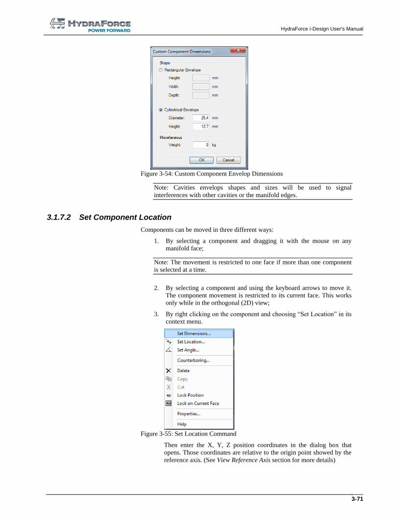
HydraForce i-Design User's Manual
3-71
Figure 3-54: Custom Component Envelop Dimensions
Note: Cavities envelops shapes and sizes will be used to signal
interferences with other cavities or the manifold edges.
3.1.7.2 Set Component Location
Components can be moved in three different ways:
1. By selecting a component and dragging it with the mouse on any
manifold face;
Note: The movement is restricted to one face if more than one component
is selected at a time.
2. By selecting a component and using the keyboard arrows to move it.
The component movement is restricted to its current face. This works
only while in the orthogonal (2D) view;
3. By right clicking on the component and choosing “Set Location” in its
context menu.
Figure 3-55: Set Location Command
Then enter the X, Y, Z position coordinates in the dialog box that
opens. Those coordinates are relative to the origin point showed by the
reference axis. (See View Reference Axis section for more details)
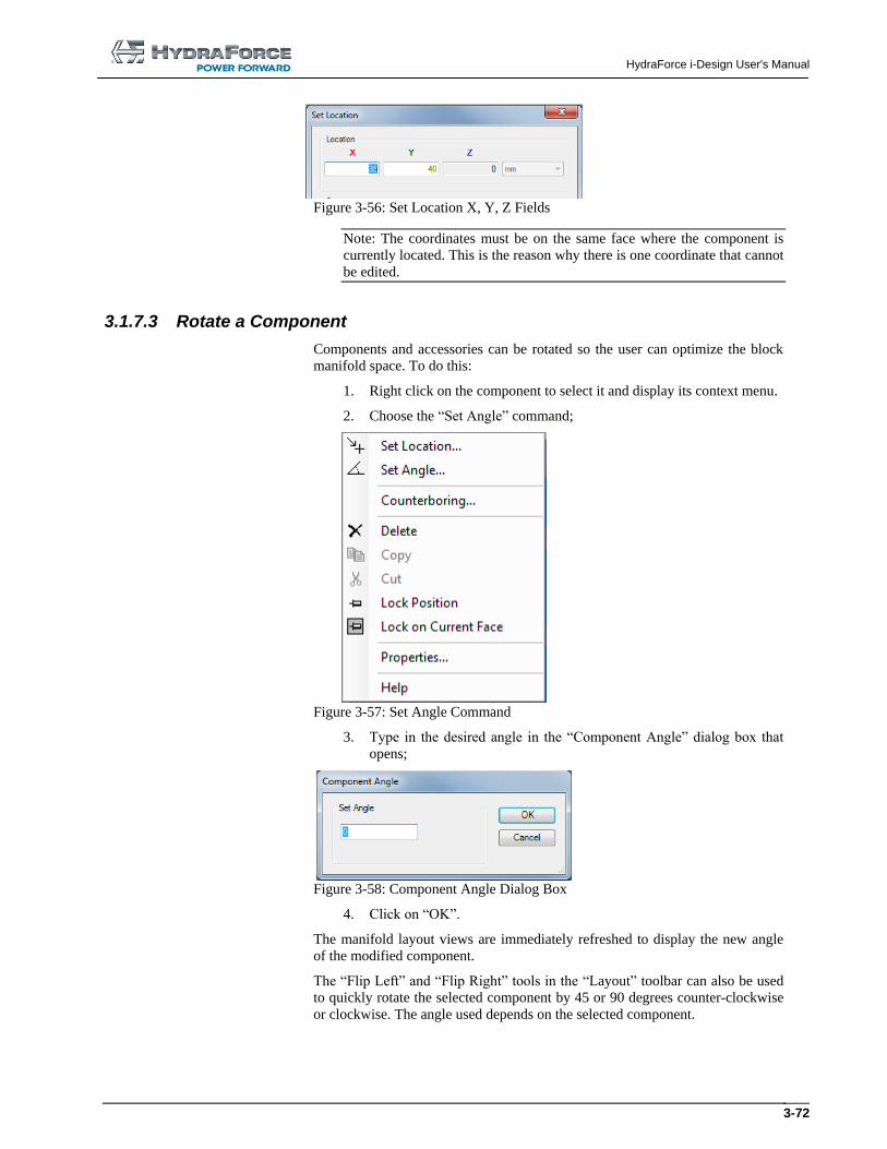
HydraForce i-Design User's Manual
3-72
Figure 3-56: Set Location X, Y, Z Fields
Note: The coordinates must be on the same face where the component is
currently located. This is the reason why there is one coordinate that cannot
be edited.
3.1.7.3 Rotate a Component
Components and accessories can be rotated so the user can optimize the block
manifold space. To do this:
1. Right click on the component to select it and display its context menu.
2. Choose the “Set Angle” command;
Figure 3-57: Set Angle Command
3. Type in the desired angle in the “Component Angle” dialog box that
opens;
Figure 3-58: Component Angle Dialog Box
4. Click on “OK”.
The manifold layout views are immediately refreshed to display the new angle
of the modified component.
The “Flip Left” and “Flip Right” tools in the “Layout” toolbar can also be used
to quickly rotate the selected component by 45 or 90 degrees counter-clockwise
or clockwise. The angle used depends on the selected component.
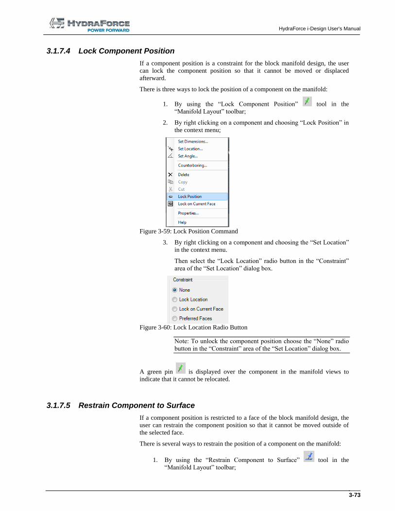
HydraForce i-Design User's Manual
3-73
3.1.7.4 Lock Component Position
If a component position is a constraint for the block manifold design, the user
can lock the component position so that it cannot be moved or displaced
afterward.
There is three ways to lock the position of a component on the manifold:
1. By using the “Lock Component Position” tool in the
“Manifold Layout” toolbar;
2. By right clicking on a component and choosing “Lock Position” in
the context menu;
Figure 3-59: Lock Position Command
3. By right clicking on a component and choosing the “Set Location”
in the context menu.
Then select the “Lock Location” radio button in the “Constraint”
area of the “Set Location” dialog box.
Figure 3-60: Lock Location Radio Button
Note: To unlock the component position choose the “None” radio
button in the “Constraint” area of the “Set Location” dialog box.
A green pin is displayed over the component in the manifold views to
indicate that it cannot be relocated.
3.1.7.5 Restrain Component to Surface
If a component position is restricted to a face of the block manifold design, the
user can restrain the component position so that it cannot be moved outside of
the selected face.
There is several ways to restrain the position of a component on the manifold:
1. By using the “Restrain Component to Surface” tool in the
“Manifold Layout” toolbar;
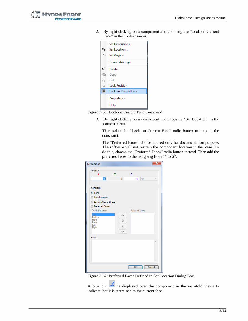
HydraForce i-Design User's Manual
3-74
2. By right clicking on a component and choosing the “Lock on Current
Face” in the context menu.
Figure 3-61: Lock on Current Face Command
3. By right clicking on a component and choosing “Set Location” in the
context menu.
Then select the “Lock on Current Face” radio button to activate the
constraint.
The “Preferred Faces” choice is used only for documentation purpose.
The software will not restrain the component location in this case. To
do this, choose the “Preferred Faces” radio button instead. Then add the
preferred faces to the list going from 1st to 6th.
Figure 3-62: Preferred Faces Defined in Set Location Dialog Box
A blue pin is displayed over the component in the manifold views to
indicate that it is restrained to the current face.
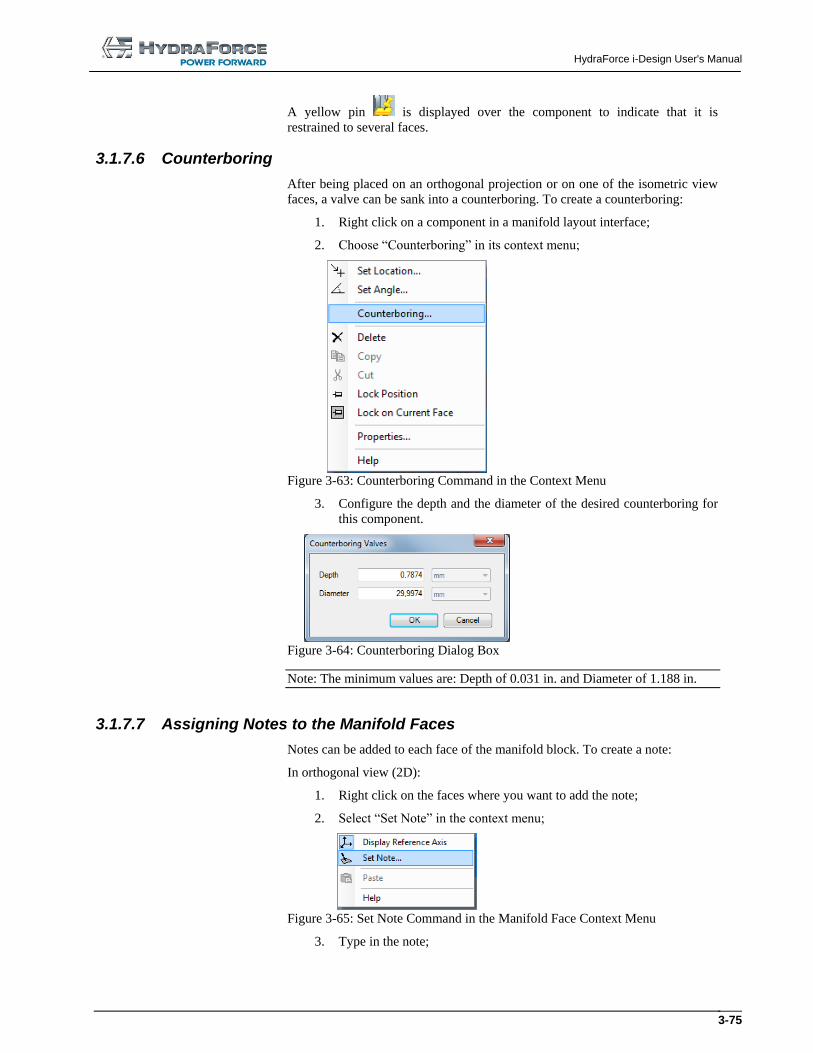
HydraForce i-Design User's Manual
3-75
A yellow pin is displayed over the component to indicate that it is
restrained to several faces.
3.1.7.6 Counterboring
After being placed on an orthogonal projection or on one of the isometric view
faces, a valve can be sank into a counterboring. To create a counterboring:
1. Right click on a component in a manifold layout interface;
2. Choose “Counterboring” in its context menu;
Figure 3-63: Counterboring Command in the Context Menu
3. Configure the depth and the diameter of the desired counterboring for
this component.
Figure 3-64: Counterboring Dialog Box
Note: The minimum values are: Depth of 0.031 in. and Diameter of 1.188 in.
3.1.7.7 Assigning Notes to the Manifold Faces
Notes can be added to each face of the manifold block. To create a note:
In orthogonal view (2D):
1. Right click on the faces where you want to add the note;
2. Select “Set Note” in the context menu;
Figure 3-65: Set Note Command in the Manifold Face Context Menu
3. Type in the note;
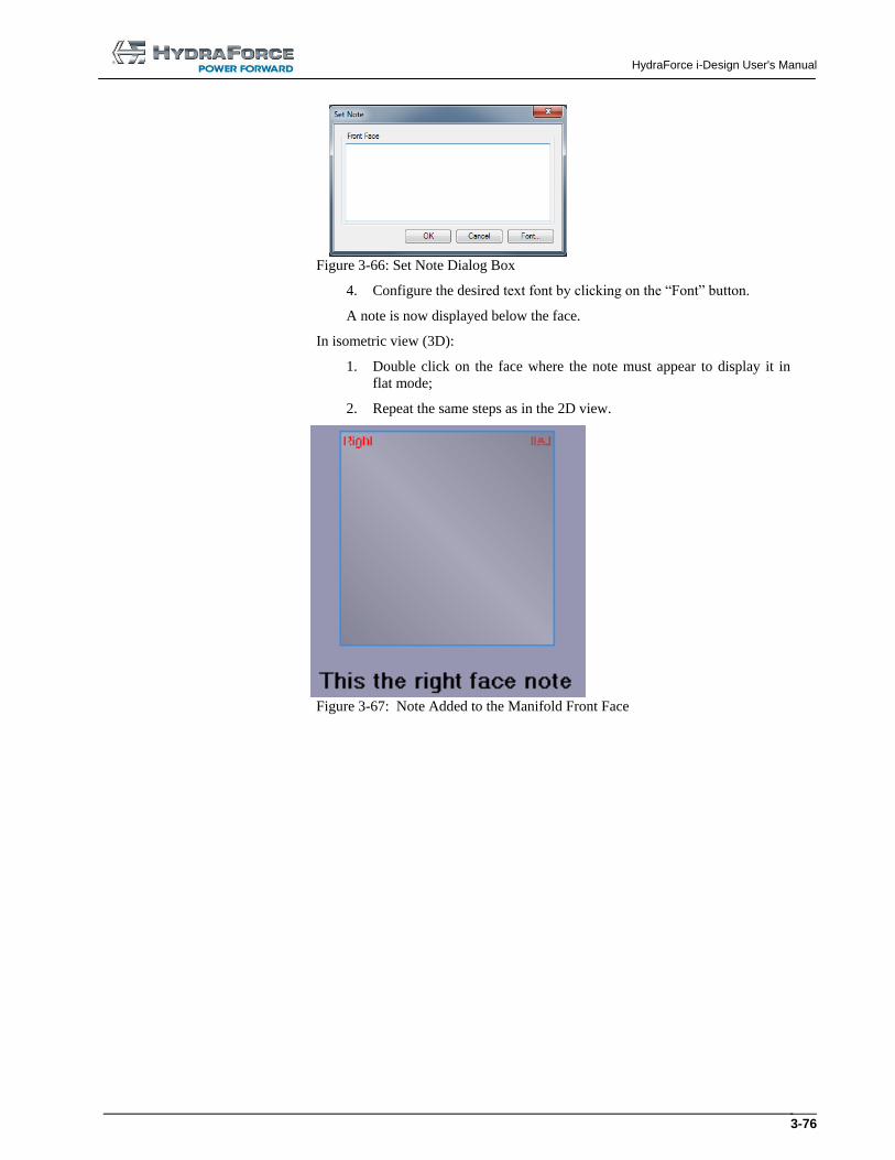
HydraForce i-Design User's Manual
3-76
Figure 3-66: Set Note Dialog Box
4. Configure the desired text font by clicking on the “Font” button.
A note is now displayed below the face.
In isometric view (3D):
1. Double click on the face where the note must appear to display it in
flat mode;
2. Repeat the same steps as in the 2D view.
Figure 3-67: Note Added to the Manifold Front Face
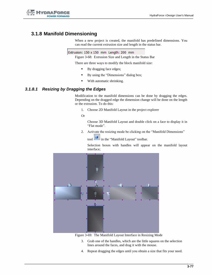
HydraForce i-Design User's Manual
3-77
3.1.8 Manifold Dimensioning
When a new project is created, the manifold has predefined dimensions. You
can read the current extrusion size and length in the status bar.
Figure 3-68: Extrusion Size and Length in the Status Bar
There are three ways to modify the block manifold size:
By dragging face edges;
By using the “Dimensions” dialog box;
With automatic shrinking.
3.1.8.1 Resizing by Dragging the Edges
Modification to the manifold dimensions can be done by dragging the edges.
Depending on the dragged edge the dimension change will be done on the length
or the extrusion. To do this:
1. Choose 2D Manifold Layout in the project explorer
Or
Choose 3D Manifold Layout and double click on a face to display it in
“Flat mode”.
2. Activate the resizing mode be clicking on the “Manifold Dimensions”
tool in the “Manifold Layout” toolbar.
Selection boxes with handles will appear on the manifold layout
interface;
Figure 3-69: The Manifold Layout Interface in Resizing Mode
3. Grab one of the handles, which are the little squares on the selection
lines around the faces, and drag it with the mouse.
4. Repeat dragging the edges until you obtain a size that fits your need.
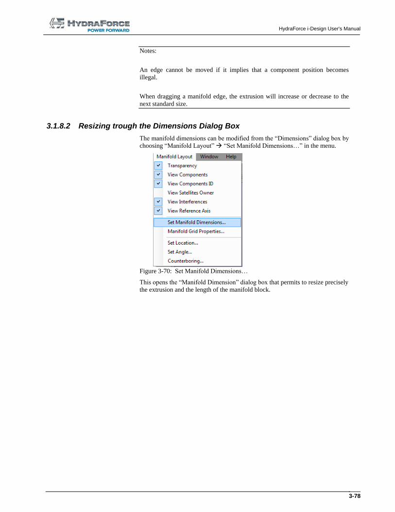
HydraForce i-Design User's Manual
3-78
Notes:
An edge cannot be moved if it implies that a component position becomes
illegal.
When dragging a manifold edge, the extrusion will increase or decrease to the
next standard size.
3.1.8.2 Resizing trough the Dimensions Dialog Box
The manifold dimensions can be modified from the “Dimensions” dialog box by
choosing “Manifold Layout” “Set Manifold Dimensions…” in the menu.
Figure 3-70: Set Manifold Dimensions…
This opens the “Manifold Dimension” dialog box that permits to resize precisely
the extrusion and the length of the manifold block.
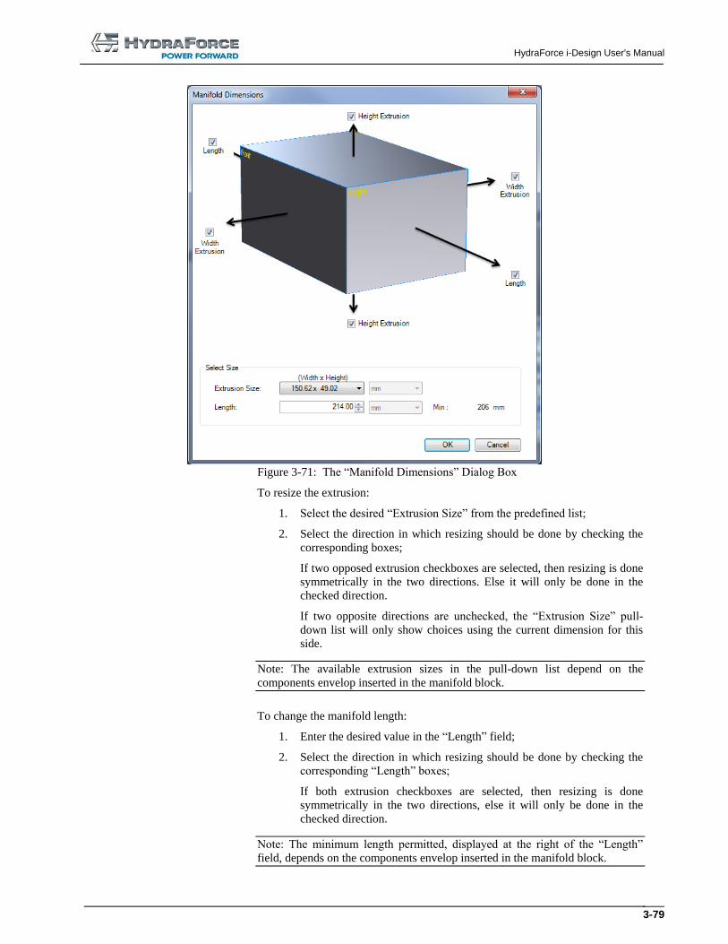
HydraForce i-Design User's Manual
3-79
Figure 3-71: The “Manifold Dimensions” Dialog Box
To resize the extrusion:
1. Select the desired “Extrusion Size” from the predefined list;
2. Select the direction in which resizing should be done by checking the
corresponding boxes;
If two opposed extrusion checkboxes are selected, then resizing is done
symmetrically in the two directions. Else it will only be done in the
checked direction.
If two opposite directions are unchecked, the “Extrusion Size” pull-
down list will only show choices using the current dimension for this
side.
Note: The available extrusion sizes in the pull-down list depend on the
components envelop inserted in the manifold block.
To change the manifold length:
1. Enter the desired value in the “Length” field;
2. Select the direction in which resizing should be done by checking the
corresponding “Length” boxes;
If both extrusion checkboxes are selected, then resizing is done
symmetrically in the two directions, else it will only be done in the
checked direction.
Note: The minimum length permitted, displayed at the right of the “Length”
field, depends on the components envelop inserted in the manifold block.
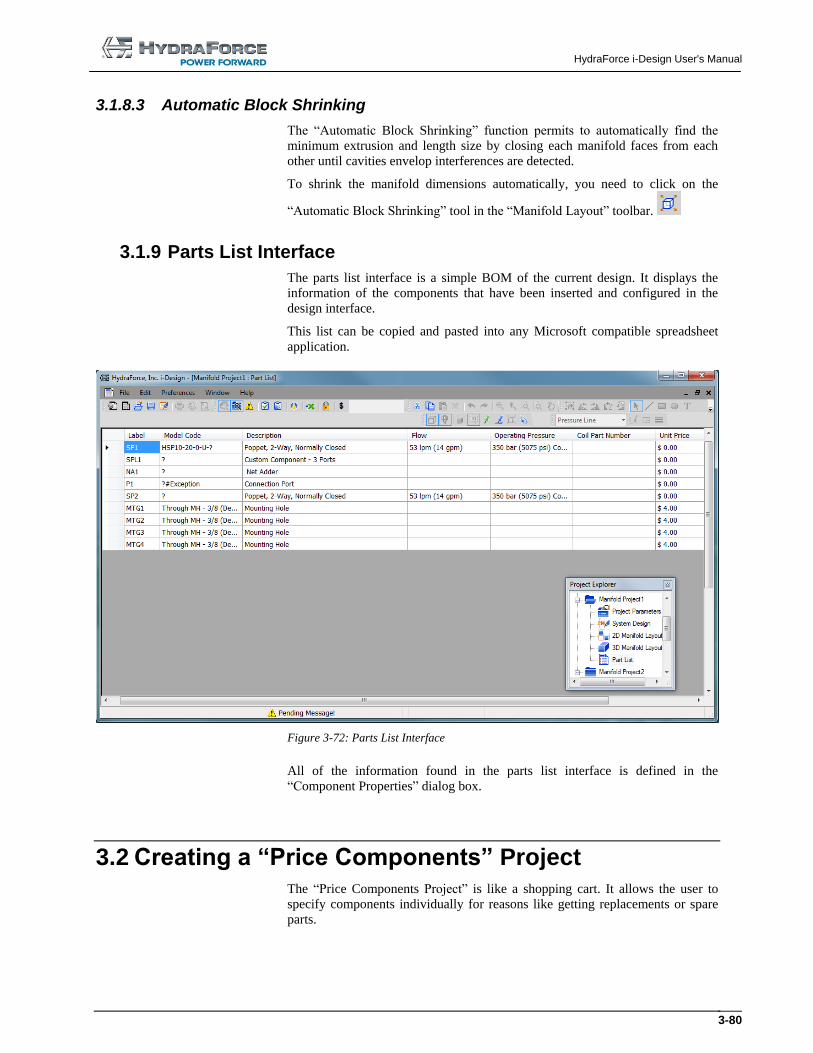
HydraForce i-Design User's Manual
3-80
3.1.8.3 Automatic Block Shrinking
The “Automatic Block Shrinking” function permits to automatically find the
minimum extrusion and length size by closing each manifold faces from each
other until cavities envelop interferences are detected.
To shrink the manifold dimensions automatically, you need to click on the
“Automatic Block Shrinking” tool in the “Manifold Layout” toolbar.
3.1.9 Parts List Interface
The parts list interface is a simple BOM of the current design. It displays the
information of the components that have been inserted and configured in the
design interface.
This list can be copied and pasted into any Microsoft compatible spreadsheet
application.
Figure 3-72: Parts List Interface
All of the information found in the parts list interface is defined in the
“Component Properties” dialog box.
3.2 Creating a “Price Components” Project The “Price Components Project” is like a shopping cart. It allows the user to
specify components individually for reasons like getting replacements or spare
parts.
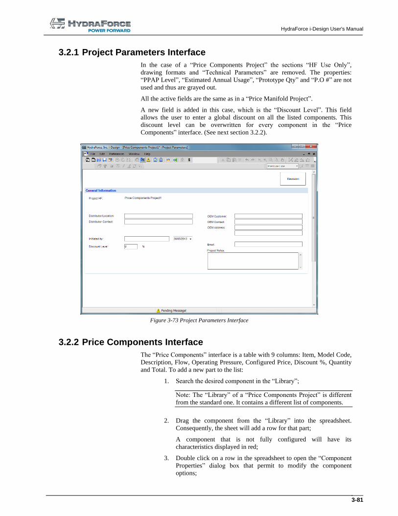
HydraForce i-Design User's Manual
3-81
3.2.1 Project Parameters Interface
In the case of a “Price Components Project” the sections “HF Use Only”,
drawing formats and “Technical Parameters” are removed. The properties:
“PPAP Level”, “Estimated Annual Usage”, “Prototype Qty” and “P.O #” are not
used and thus are grayed out.
All the active fields are the same as in a “Price Manifold Project”.
A new field is added in this case, which is the “Discount Level”. This field
allows the user to enter a global discount on all the listed components. This
discount level can be overwritten for every component in the “Price
Components” interface. (See next section 3.2.2).
Figure 3-73 Project Parameters Interface
3.2.2 Price Components Interface
The “Price Components” interface is a table with 9 columns: Item, Model Code,
Description, Flow, Operating Pressure, Configured Price, Discount %, Quantity
and Total. To add a new part to the list:
1. Search the desired component in the “Library”;
Note: The “Library” of a “Price Components Project” is different
from the standard one. It contains a different list of components.
2. Drag the component from the “Library” into the spreadsheet.
Consequently, the sheet will add a row for that part;
A component that is not fully configured will have its
characteristics displayed in red;
3. Double click on a row in the spreadsheet to open the “Component
Properties” dialog box that permit to modify the component
options;
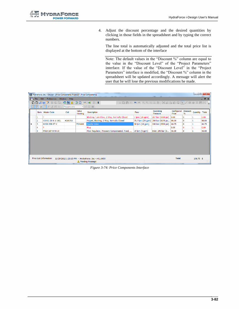
HydraForce i-Design User's Manual
3-82
4. Adjust the discount percentage and the desired quantities by
clicking in those fields in the spreadsheet and by typing the correct
numbers.
The line total is automatically adjusted and the total price list is
displayed at the bottom of the interface
Note: The default values in the “Discount %” column are equal to
the value in the “Discount Level” of the “Project Parameters”
interface. If the value of the “Discount Level” in the “Project
Parameters” interface is modified, the “Discount %” column in the
spreadsheet will be updated accordingly. A message will alert the
user that he will lose the previous modifications he made.
Figure 3-74: Price Components Interface
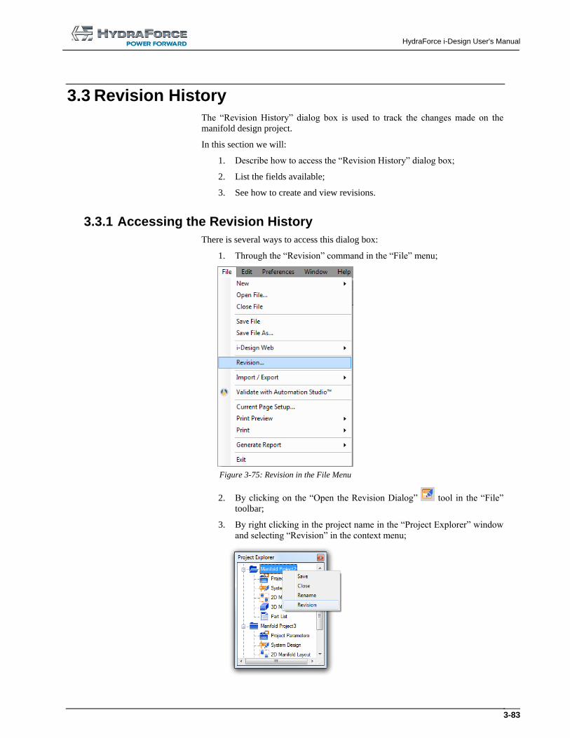
HydraForce i-Design User's Manual
3-83
3.3 Revision History The “Revision History” dialog box is used to track the changes made on the
manifold design project.
In this section we will:
1. Describe how to access the “Revision History” dialog box;
2. List the fields available;
3. See how to create and view revisions.
3.3.1 Accessing the Revision History
There is several ways to access this dialog box:
1. Through the “Revision” command in the “File” menu;
Figure 3-75: Revision in the File Menu
2. By clicking on the “Open the Revision Dialog” tool in the “File”
toolbar;
3. By right clicking in the project name in the “Project Explorer” window
and selecting “Revision” in the context menu;
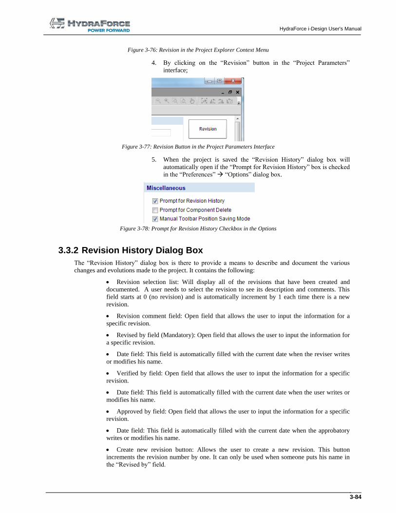
HydraForce i-Design User's Manual
3-84
Figure 3-76: Revision in the Project Explorer Context Menu
4. By clicking on the “Revision” button in the “Project Parameters”
interface;
Figure 3-77: Revision Button in the Project Parameters Interface
5. When the project is saved the “Revision History” dialog box will
automatically open if the “Prompt for Revision History” box is checked
in the “Preferences” “Options” dialog box.
Figure 3-78: Prompt for Revision History Checkbox in the Options
3.3.2 Revision History Dialog Box
The “Revision History” dialog box is there to provide a means to describe and document the various
changes and evolutions made to the project. It contains the following:
Revision selection list: Will display all of the revisions that have been created and
documented. A user needs to select the revision to see its description and comments. This
field starts at 0 (no revision) and is automatically increment by 1 each time there is a new
revision.
Revision comment field: Open field that allows the user to input the information for a
specific revision.
Revised by field (Mandatory): Open field that allows the user to input the information for
a specific revision.
Date field: This field is automatically filled with the current date when the reviser writes
or modifies his name.
Verified by field: Open field that allows the user to input the information for a specific
revision.
Date field: This field is automatically filled with the current date when the user writes or
modifies his name.
Approved by field: Open field that allows the user to input the information for a specific
revision.
Date field: This field is automatically filled with the current date when the approbatory
writes or modifies his name.
Create new revision button: Allows the user to create a new revision. This button
increments the revision number by one. It can only be used when someone puts his name in
the “Revised by” field.
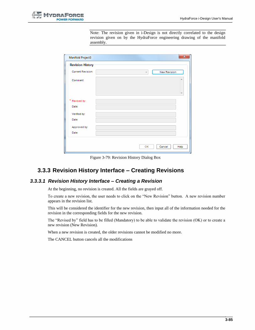
HydraForce i-Design User's Manual
3-85
Note: The revision given in i-Design is not directly correlated to the design
revision given on by the HydraForce engineering drawing of the manifold
assembly.
Figure 3-79: Revision History Dialog Box
3.3.3 Revision History Interface – Creating Revisions
3.3.3.1 Revision History Interface – Creating a Revision
At the beginning, no revision is created. All the fields are grayed off.
To create a new revision, the user needs to click on the “New Revision” button. A new revision number
appears in the revision list.
This will be considered the identifier for the new revision, then input all of the information needed for the
revision in the corresponding fields for the new revision.
The “Revised by” field has to be filled (Mandatory) to be able to validate the revision (OK) or to create a
new revision (New Revision).
When a new revision is created, the older revisions cannot be modified no more.
The CANCEL button cancels all the modifications
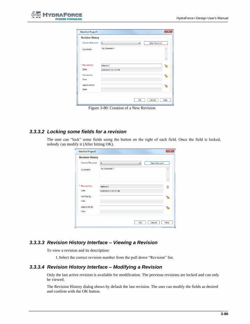
HydraForce i-Design User's Manual
3-86
Figure 3-80: Creation of a New Revision
3.3.3.2 Locking some fields for a revision
The user can “lock” some fields using the button on the right of each field. Once the field is locked,
nobody can modify it (After hitting OK).
3.3.3.3 Revision History Interface – Viewing a Revision
To view a revision and its description:
1. Select the correct revision number from the pull down “Revision” list.
3.3.3.4 Revision History Interface – Modifying a Revision
Only the last active revision is available for modification. The previous revisions are locked and can only
be viewed.
The Revision History dialog shows by default the last revision. The user can modify the fields as desired
and confirm with the OK button.
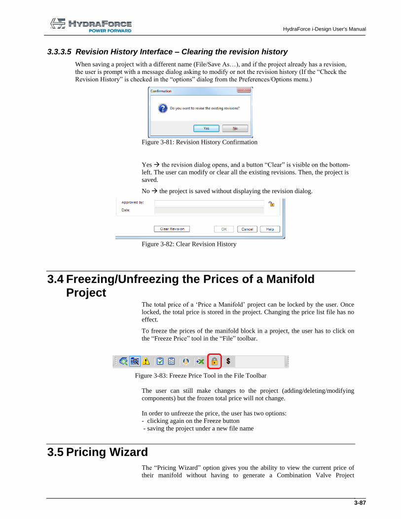
HydraForce i-Design User's Manual
3-87
3.3.3.5 Revision History Interface – Clearing the revision history
When saving a project with a different name (File/Save As…), and if the project already has a revision,
the user is prompt with a message dialog asking to modify or not the revision history (If the “Check the
Revision History” is checked in the “options” dialog from the Preferences/Options menu.)
Figure 3-81: Revision History Confirmation
Yes the revision dialog opens, and a button “Clear” is visible on the bottom-
left. The user can modify or clear all the existing revisions. Then, the project is
saved.
No the project is saved without displaying the revision dialog.
Figure 3-82: Clear Revision History
3.4 Freezing/Unfreezing the Prices of a Manifold Project
The total price of a ‘Price a Manifold’ project can be locked by the user. Once
locked, the total price is stored in the project. Changing the price list file has no
effect.
To freeze the prices of the manifold block in a project, the user has to click on
the “Freeze Price” tool in the “File” toolbar.
Figure 3-83: Freeze Price Tool in the File Toolbar
The user can still make changes to the project (adding/deleting/modifying
components) but the frozen total price will not change.
In order to unfreeze the price, the user has two options:
- clicking again on the Freeze button
- saving the project under a new file name
3.5 Pricing Wizard The “Pricing Wizard” option gives you the ability to view the current price of
their manifold without having to generate a Combination Valve Project

HydraForce i-Design User's Manual
3-88
Worksheet pricing report. This option is only available to those with access to
the HydraForce Pricelist update.
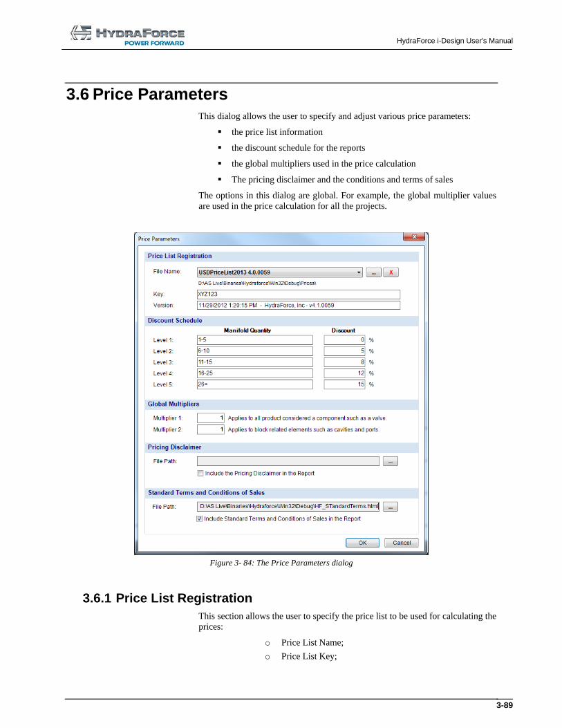
HydraForce i-Design User's Manual
3-89
3.6 Price Parameters This dialog allows the user to specify and adjust various price parameters:
the price list information
the discount schedule for the reports
the global multipliers used in the price calculation
The pricing disclaimer and the conditions and terms of sales
The options in this dialog are global. For example, the global multiplier values
are used in the price calculation for all the projects.
Figure 3- 84: The Price Parameters dialog
3.6.1 Price List Registration
This section allows the user to specify the price list to be used for calculating the
prices:
o Price List Name;
o Price List Key;
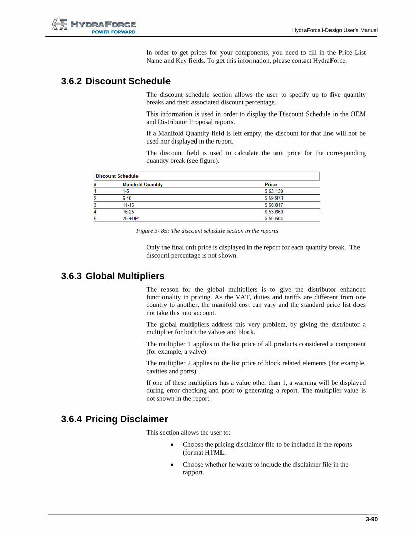
HydraForce i-Design User's Manual
3-90
In order to get prices for your components, you need to fill in the Price List
Name and Key fields. To get this information, please contact HydraForce.
3.6.2 Discount Schedule
The discount schedule section allows the user to specify up to five quantity
breaks and their associated discount percentage.
This information is used in order to display the Discount Schedule in the OEM
and Distributor Proposal reports.
If a Manifold Quantity field is left empty, the discount for that line will not be
used nor displayed in the report.
The discount field is used to calculate the unit price for the corresponding
quantity break (see figure).
Figure 3- 85: The discount schedule section in the reports
Only the final unit price is displayed in the report for each quantity break. The
discount percentage is not shown.
3.6.3 Global Multipliers
The reason for the global multipliers is to give the distributor enhanced
functionality in pricing. As the VAT, duties and tariffs are different from one
country to another, the manifold cost can vary and the standard price list does
not take this into account.
The global multipliers address this very problem, by giving the distributor a
multiplier for both the valves and block.
The multiplier 1 applies to the list price of all products considered a component
(for example, a valve)
The multiplier 2 applies to the list price of block related elements (for example,
cavities and ports)
If one of these multipliers has a value other than 1, a warning will be displayed
during error checking and prior to generating a report. The multiplier value is
not shown in the report.
3.6.4 Pricing Disclaimer
This section allows the user to:
Choose the pricing disclaimer file to be included in the reports
(format HTML.
Choose whether he wants to include the disclaimer file in the
rapport.
HydraForce i-Design User's Manual
3-91
3.6.5 Standard Terms and Conditions of Sales
This section allows the user to:
Choose the standard terms and conditions of sales file to be
included in the reports (format HTML).
Choose whether he wants to include this file in the rapport.
3.7 Software Options Software options permit to customize some parameters globally in the
application. The options include:
1. Title Block:
o Company name;
o The disclaimer that appear in the title block;
o The option to activate globally the title blocks insertion. It
is checked by default;
o “Apply to Current Diagram” changes done on the
company name and disclaimer fields.
2. Settings:
o Language;
o Units used trough out the application: Imperial or Metric.
It cannot be modified for after a project has been created.
o View Models in Library From different levels
(Component Families);
3. Miscellaneous:
o Prompt for revision history when saving a project. It is
checked by default;
o Prompt for component delete;
o Toolbar Position Saving Mode (Manual or Automatic)
o Automatic Catalog File Update (pdf). Get from a
HydraForce’s server.
o Show tip message to convert 3D environment. If checked,
a message will be displayed when a project saved with the
previous version of i-Design is opened. It is checked by
default;
o Show warning if insufficient video memory. If checked, a
warning message will be displayed when starting I-
Design if the video memory is less than the recommended
value (128 Mb). This option is checked by default;
o Ask for confirmation for the ‘Fit to Block’ function. If
checked, a confirmation dialog will be displayed each
time that the user clicks the ‘Resize to Fit’ button in the
Manifold Layout Toolbar ( ). This option is checked
by default;
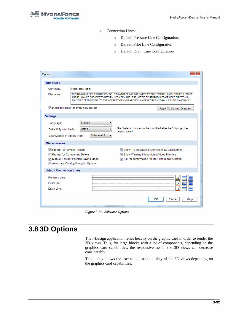
HydraForce i-Design User's Manual
3-92
4. Connection Lines:
o Default Pressure Line Configuration;
o Default Pilot Line Configuration
o Default Drain Line Configuration
Figure 3-86: Software Options
3.8 3D Options The i-Design application relies heavily on the graphic card in order to render the
3D views. Thus, for large blocks with a lot of components, depending on the
graphics card capabilities, the responsiveness in the 3D views can decrease
considerably.
This dialog allows the user to adjust the quality of the 3D views depending on
the graphics card capabilities:
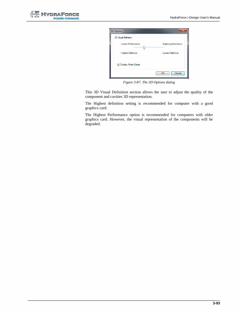
HydraForce i-Design User's Manual
3-93
Figure 3-87: The 3D Options dialog
This 3D Visual Definition section allows the user to adjust the quality of the
component and cavities 3D representation.
The Highest definition setting is recommended for computer with a good
graphics card.
The Highest Performance option is recommended for computers with older
graphics card. However, the visual representation of the components will be
degraded.
HydraForce i-Design User's Manual
3-94
3.9 Best Practices for Cost Effective Design The following guidelines should be considered during manifold design to ensure
you receive the most cost effective manifold assembly.
3.9.1 General Design Considerations
1. All designs are subject to change in size shape and layout at the desecration
of the designer. The 3D design tool in i-Design is for the sole purpose to
give the user an estimate of what the design might look like.
2. When valves, ports and mounting holes are placed on the manifold surface
portions of the components may turn red. This is to indicate that the
components are too close together. To visualize a manifold that most likely
can be realized in an actual design, move the components and expand the
block size until none of the elements are red.
3. Open Design; it is best to leave the design open to the discretion of the
manifold designer. The valves and ports can be placed on the various
surfaces to get an idea of the overall manifold size. However, if these
elements are not specifically constrained the designer will assume the design
is open. In general the designer does try to limit the number of surfaces
where ports and valves are place. The designer does try to group the work
ports in a logical order. For example, the A and B port for a given
directional control will typically be on the same surface. At least one surface
will be free of valves or valves protruding from the surface so that this
surface can serve as the mounting surface. The open design is denoted by a
note on the Project Parameter page under Technical Parameters.
4. Constraints; if the machine design dictates that some of the valves or ports
must be on a given surface clearly mark these components as such. The
constraint can be applied be right clicking on the valve or port while in the
2D or 3D layout screens and then selecting set location. The constrained
design is denoted by a note on the Project Parameter page under Technical
Parameters.
o It is recommended that the user does not constrain all
valves and ports. This may force the size of the manifold
to be objectionably large or the designer may not be able to
accommodate the request. In general do not constrain
valves that do not have coils or adjustments, for example
CV’s, EC’s and PD’s.
5. Manifold surface names: The manifold surface names may have no relation
to how a manifold is installed in a machine. These names were placed on the
surface to facilitate discussion between HF sales and engineering as well as
with our customer.
HydraForce i-Design User's Manual
3-95
6. Size of manifold body:
a. The left and right face of the body is limited by standard material sizes available to HF. The length of the manifold increments by 0.5 inch, or 10 mm.
b. Once components have been placed the overall size of the manifold can be reduced by selecting the Fit Block to Components icon. If space still remains between components these can be moved closer and the icon selected again.
3.9.2 Valve Placement Suggestions
1. Five and six ported solenoid operated valves: We recommend that these valves be placed on the top surface.
2. Five and six ported PD’s and PE’s: We recommend that these valves be placed on the left or right surface. After these valves are placed the valve that controls the pilot pressure to the pilot of these valves can then be placed on a surface that is perpendicular to the left or right face. It is suggested that this pilot valve be located near the pilot port.
3. Valves with manual adjustments: These valves can be placed on any surface that is convenient for accessing these adjustments when the manifold is installed in the machine.
4. Non-adjustable valves: Non-adjustable valves can be placed on any surface.
3.9.3 Port Placement Suggestions
1. We recommend placing the work ports after placing the associated valve.
These ports normally are placed on the surface perpendicular to the valve
cavity axis. The exception could be that the port related to the valve port 1
can be placed in line with the cavity axis.
HydraForce i-Design User's Manual
3-96
3.9.4 Manifold Mounting Holes and Mounting Surface
1. Mounting surface: Remember during the valve and port placement that at
least one surface will be required to mount the manifold. It is recommended
that no ports be place on this surface. Low profile, non-adjustable valves can
be placed on this surface. The cavity and valve can be counter sunk below
the surface using the counter bore tool.
2. Mounting holes: After the valves and ports have been placed and the
manifold size has been minimized the mounting holes can be placed.
HydraForce i-Design User's Manual
4-97
4 Documentation (B.O.M)
4.1 Introduction The report is the main objective of i-Design application. It permits to
communicate to HydraForce all the information required to build your manifold
block. It includes: the components list, placement, configuration, the manifold
parameters and the costs.
Note: If no pricing appears in the report, contact HydraForce to get the most
recent price list and its key. The price list file needs to be copied in i-Design root
folder. The price list file name and key information must be entered in the
“Preferences” “Options” dialog box.
4.2 Generating the report To generate the report:
1. Click on the “Generate Standard Report” tool in the “File”
toolbar or
2. Choose one of the three options of the “File/Generate Report”
menu.
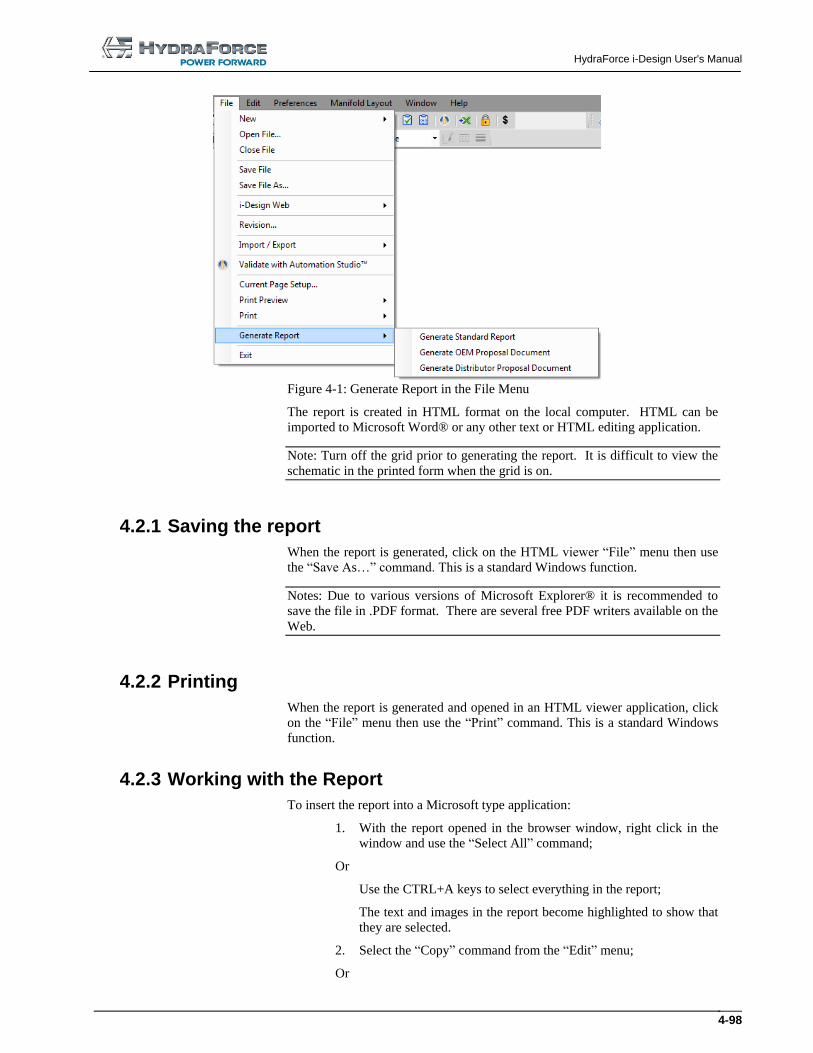
HydraForce i-Design User's Manual
4-98
Figure 4-1: Generate Report in the File Menu
The report is created in HTML format on the local computer. HTML can be
imported to Microsoft Word® or any other text or HTML editing application.
Note: Turn off the grid prior to generating the report. It is difficult to view the
schematic in the printed form when the grid is on.
4.2.1 Saving the report
When the report is generated, click on the HTML viewer “File” menu then use
the “Save As…” command. This is a standard Windows function.
Notes: Due to various versions of Microsoft Explorer® it is recommended to
save the file in .PDF format. There are several free PDF writers available on the
Web.
4.2.2 Printing
When the report is generated and opened in an HTML viewer application, click
on the “File” menu then use the “Print” command. This is a standard Windows
function.
4.2.3 Working with the Report
To insert the report into a Microsoft type application:
1. With the report opened in the browser window, right click in the
window and use the “Select All” command;
Or
Use the CTRL+A keys to select everything in the report;
The text and images in the report become highlighted to show that
they are selected.
2. Select the “Copy” command from the “Edit” menu;
Or
HydraForce i-Design User's Manual
4-99
Use the CTRL+C keys to send all of the information to the
clipboard.
3. Open the desired application;
4. Select the “Paste” command;
Or
Use the CTRL+V keys to paste the information in the targeted
application.
4.2.4 Report Contents
The report contents will vary depending on the design. For a standard report,
the following information is included:
Section 1: Project information sheet;
Section 2: Technical information;
Section 3: Manifold layout in orthogonal view (2D);
Section 4: Manifold layout in isometric view (3D);
Section 5: Bill of material and pricing;
Section 6: Manifold summary information;
Section 7: Net adder components;
Section 8: Placement constraints;
Section 9: Revision history;
Section 10: Warnings and revision history page;
Section 11: Disclaimer and hydraulic diagram.
Section 12: Standard terms and conditions of sales.

HydraForce i-Design User's Manual
4-100
HydraForce i-Design User's Manual
5-101
5 Index
2D Manifold Layout, 2-11, 3-34
3D Conversion, 2-22
3D Manifold Layout, 2-11
3D Options, 3-67
3D view quality, 3-67
Automatic Manifold Block Resizing, 3-55
Automation Studio Format, 2-21
Axis, 3-42
Catalog Information, 3-23
Cavities Only View, 3-39
Cavity, 3-22
Closing, 2-10
Coil Voltage, 3-4
Color, 3-17
Colors Selection, 3-18
Component
Buried, 3-33
Copy, 3-12
Counterboring, 3-50
Custom, 3-23, 3-32
Cut, 3-12
Delete, 3-12
Dimensions, 3-45
Flip, 3-14
Identifier, 3-22
Location, 3-46
Lock Position, 3-48
Model, 3-20
Move, 3-14
Multiple Select, 3-11
Net Adder, 3-24
Paste, 3-13
Properties, 3-19
Rapid Copy/Paste, 3-13
Restrain to Surface, 3-48
Rotate, 3-13, 3-47
Select, 3-11
Snap, 3-9
Components Configurations, 3-45
Connect Components, 3-26
Contents, 1-1
Context Menus, 3-14
Converting to 3D, 2-22
Copy, 3-12
Copy/Paste, 3-13
Counterboring, 3-50
Current Page Setup, 3-7
Custom Components, 3-23
Cut, 3-12
Default Page Setup, 3-7
Delete, 3-12
Diagram Editor, 3-4, 3-6
Dimension Line, 3-18
Discount and Multipliers, 3-64
Discount Schedule, 3-65
Global Multipliers, 3-65
Displayed Information, 3-22
Drawing Surface, 3-6
DXF Format, 2-18
Ellipse, 3-15
Export
3D Components to a Folder, 2-19
Automation Studio, 2-21
DXF, 2-18
XML 3D, 2-20
File
Create, 2-13
New, 2-13
Open, 2-13
Save, 2-15
Save As…, 2-16
Flip, 3-14
Freezing Prices, 3-62
General Information, 3-3
Graphic Elements, 3-15
Grid, 3-6
Activating, 3-9
Manifold, 3-43
Header Section, 2-1
Import from XML, 2-21
Inserting Components, 3-11
Interface
2D Manifold Layout, 3-34
Component Properties, 3-19
Header Section, 2-1
Main Display, 2-1
HydraForce i-Design User's Manual
5-102
Navigation Pane, 2-1
Parts List, 3-55
Price Components, 3-56
Price Components Project Parameters, 3-56
Project Parameters, 3-1
System Design, 3-4
Interferences, 3-41
Library Explorer, 3-5
Line, 3-15
Cross Settings, 3-27
Jump, 3-27
Thickness, 3-18
Link
Create, 3-26
Modify, 3-26
Lock Component Position, 3-48
Main Design Interface, 3-5
Main Display, 2-1, 2-11
Main Interface, 2-1
Manifold
Automatic Shrinking, 3-55
Border, 3-31
Component Library, 3-35
Components, 3-36
Dimensioning, 3-52
Edges Resizing, 3-52
Grid, 3-43
Notes, 3-50
Ports, 3-31, 3-35
Resizing Dialog Box, 3-53
Views, 3-38
Manifold Component
Inserting, 3-37
Managing, 3-37
Manifold Layout
2D, 3-34
Editor, 3-37
Interfaces, 3-34
Manual Overrides, 3-21
Menu
Contents, 2-3
Edit, 2-3
File, 2-3
Help, 2-3
Manifold Layout, 2-3
Options, 2-3
Preferences, 2-3
Menus, 2-3
Model Code Configuration, 3-21
Modifying Text Attributes, 3-16
Mounting Holes, 3-36
Defining, 3-38
Move, 3-14
Multiple File Management, 2-10
Navigation Pane, 2-1
Net Adder, 3-24
New File, 2-13
Notes, 3-50
Open File, 2-13
Open v2.0 File, 2-14
Options, 3-63, 3-66
Grid, 2-5
Help, 2-5
Orifice Disks, 3-32
Orifice Plugs, 3-32
Orthogonal Manifold Layout Interface, 3-34
Other Component Envelop, 3-45
Other Components, 3-32
Pan, 3-10
Parts Library, 3-4
Parts List, 3-55
Paste, 3-13
Performance, 3-67
Picture, 3-16
Ports, 3-31
Deleting, 3-37
Inserting, 3-37
Managing, 3-37
Manifold, 3-31
Price Components Interface, 3-56
Price Components Project Parameters Interface, 3-56
Price Unfreezing, 3-62
Prices Freezing, 3-62
Print, 2-17
Print Preview, 2-17
Project Parameters, 2-11
Price a Manifold, 3-1
Price Components, 3-56
Rectangle, 3-15
Reference Axis, 3-42
Renaming, 2-10
Report
Contents, 4-74
Generating, 4-72
Importing, 4-73
Resizing
Dialog Box, 3-53
Dragging the Edges, 3-52
Manifold Automatically, 3-55
Restrain to Surface, 3-48
Revision
History, 2-10
Modify, 3-61
Rotate, 3-13
Rotate a Component, 3-47
Satellite Owner Lines, 3-40
Save File, 2-15
Save v2.0 File, 2-16, 2-19, 2-21, 2-22
Saving, 2-10
Screens, 3-21
Seal Type, 3-4
Search in Library, 3-5
Set Location, 3-46
Snap, 3-9
HydraForce i-Design User's Manual
5-103
Software Options, 3-63, 3-66
System Boundary, 3-31
System Design, 2-11
System Design Interface, 3-4
Technical Parameters, 3-3
Text Box, 3-16
Toolbar
Connection, 2-8
Edit, 2-6
File, 2-6
Insert, 2-7
Layout, 2-7
Manifold Layout, 2-8
View, 2-7
Transparency, 3-38
Unfreezing Prices, 3-62
View
Cavities Only, 3-39
Component Properties, 3-15
Component’s ID, 3-40
Connection Port, 3-19
Interferences, 3-41
Manifold Grid, 3-43
Port Names, 3-19
Reference Axis, 3-42
Revision, 3-61
Satellite Owner, 3-40
Transparency, 3-38
Warning Messages, 2-11
XML 3D Export, 2-20
XML 3D Import, 2-21
Zoom, 3-7, 3-9
Zoom-all, 3-10
Zoom-in, 3-9
Zoom-out, 3-10