Embed Size (px)
Citation preview
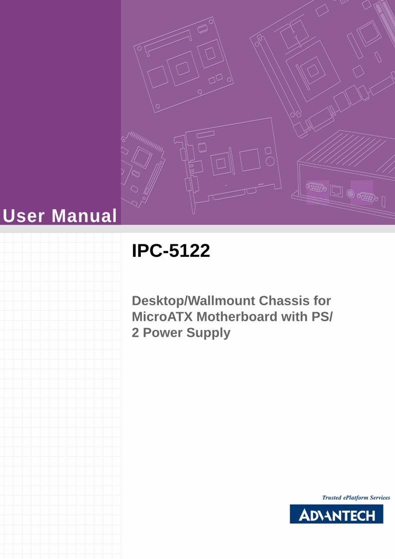
User Manual
IPC-5122
Desktop/Wallmount Chassis for MicroATX Motherboard with PS/2 Power Supply
CopyrightThe documentation and the software included with this product are copyrighted 2009by Advantech Co., Ltd. All rights are reserved. Advantech Co., Ltd. reserves the rightto make improvements in the products described in this manual at any time withoutnotice. No part of this manual may be reproduced, copied, translated or transmittedin any form or by any means without the prior written permission of Advantech Co.,Ltd. Information provided in this manual is intended to be accurate and reliable. How-ever, Advantech Co., Ltd. assumes no responsibility for its use, nor for any infringe-ments of the rights of third parties, which may result from its use.
AcknowledgementsIntel®, Pentium® M, Core 2 Duo® and Core 2 Quad® are trademarks of Intel Corpo-ration.The IPC-5122, AIMB-566, AIMB-564, AIMB-562, AIMB-556, AIMB-554, AIMB-552are trademarks of Advantech Co., Ltd.All other product names or trademarks are the properties of their respective owners.
On-Line Technical Support
For technical support and service, please visit our support website at:http://www.advantech.com/support
Part No. 2002512200 Edition 1Printed in China May 2009
IPC-5122 User Manual ii

spray detergents for cleaning. 4. For pluggable equipment, the power outlet shall be installed near the equipment
and shall be easily accessible.5. Keep this equipment away from humidity.6. Put this equipment on a reliable surface during installation. Dropping it or letting
it fall could cause damage.7. Do not leave this equipment in an environment unconditioned where the storage
temperature under 0°C (32°F) or above 40°C (104°F), it may damage the equip-ment.
8. The openings on the enclosure are for air convection hence protects the equip-ment from overheating. DO NOT COVER THE OPENINGS.
9. Make sure the voltage of the power source is correct before connecting the equipment to the power outlet.
10. Place the power cord such a way that people can not step on it. Do not place anything over the power cord. The voltage and current rating of the cord should be greater than the voltage and current rating marked on the product.
11. All cautions and warnings on the equipment should be noted.12. If the equipment is not used for long time, disconnect it from the power source to
avoid being damaged by transient over-voltage.13. Never pour any liquid into ventilation openings. This could cause fire or electri-
cal shock.14. Never open the equipment. For safety reasons, the equipment should be
opened only by qualified service personnel.15. If any of the following situations arises, get the equipment checked by service
personnel:a. The power cord or plug is damaged.b. Liquid has penetrated into the equipment.c. The equipment has been exposed to moisture.d. The equipment does not work well or you cannot get it to work according to
user manual.e. The equipment has been dropped and damaged.f. The equipment has obvious signs of breakage.
16. CAUTION: The computer is provided with a battery-powered real-time clock cir-cuit. There is a danger of explosion if battery is incorrectly replaced. Replace only with same or equivalent type recommended by the manufacture. Discard used batteries according to the manufacturer’s instructions.
17. THE COMPUTER IS PROVIDED WITH CD DRIVES COMPLY WITH APPRO-PRIATE SAFETY STANDARDS INCLUDING IEC 60825.
CLASS 1 LASER PRODUCT KLASSE 1 LASER PRODUKT
iii IPC-5122 User Manual
18. This device complies with Part 15 of the FCC rules. Operation is subject to the following two conditions:1). This device may not cause harmful interference, and 2). This device must accept any interference received, including interference
that may cause undesired operation.19. CAUTION: Always completely disconnect the power cord from your chassis
whenever you work with the hardware. Do not make connections while the power is on. Sensitive electronic components can be damaged by sudden power surges.
20. CAUTION: Always ground yourself to remove any static charge before touching the motherboard, backplane, or add-on cards. Modern electronic devices are very sensitive to static electric charges. As a safety precaution, use a grounding wrist strap at all times. Place all electronic components on a static-dissipative surface or in a static-shielded bag when they are not in the chassis.
21. CAUTION: Any unverified component could cause unexpected damage. To ensure the correct installation, please always use the components (ex. screws) provided with the accessory box.
A Message to the Customer
Advantech Customer Services
Each and every Advantech product is built to the most exacting specifications toensure reliable performance in the harsh and demanding conditions typical of indus-trial environments. Whether your new Advantech equipment is destined for the labo-ratory or the factory floor, you can be assured that your product will provide thereliability and ease of operation for which the name Advantech has come to beknown. Your satisfaction is our primary concern. Here is a guide to Advantech's cus-tomer services. To ensure you get the full benefit of our services, please follow theinstructions below carefully.
Technical Support
We want you to get the maximum performance from your products. If you run intotechnical difficulties, we are here to help. For the most frequently asked questions,you can easily find answers in your product documentation. These answers are nor-mally a lot more detailed than the ones we can give over the phone.Please consult this manual first. If you still cannot find the answer, gather all the infor-mation or questions that apply to your problem, and with the product close at hand,call your dealer. Our dealers are well trained and ready to give you the support youneed to get the most from your Advantech products. In fact, most problems reportedare minor and are easily solved over the phone.In addition, free technical support is available from Advantech engineers every busi-ness day. We are always ready to give advice on application requirements or specificinformation on the installation and operation of any of our products.
IPC-5122 User Manual iv

speed, Advantech products used, other hardware and software used, etc.) Note anything abnormal and list any onscreen messages you get when the problem occurs.
2. Call your dealer and describe the problem. Please have your manual, product, and any helpful information readily available.
3. If your product is diagnosed as defective, obtain an RMA (return merchandize authorization) number from your dealer. This allows us to process your return more quickly.
4. Carefully pack the defective product, a fully-completed Repair and Replacement Order Card and a photocopy proof of purchase date (such as your sales receipt) in a shippable container. A product returned without proof of the purchase date is not eligible for warranty service.
5. Write the RMA number visibly on the outside of the package and ship it prepaid to your dealer.
Initial InspectionWhen you open the carton, please make sure that the following materials have beenshipped:
IPC-5122 ChassisUser ManualWarranty CardAccessory box with four rubber foots, a pair of wallmount brackets, and a pack-age of screws (for fastening the motherboard, disk drives, rubber foots or wall-mount brackets, etc.)
If any of these items are missing or damaged, contact your distributor or sales repre-sentative immediately. We have carefully inspected the IPC-5122 mechanically andelectrically before shipment. It should be free of marks and scratches and in perfectworking order upon receipt. As you unpack the IPC-5122, check it for signs of ship-ping damage. (For example, damaged box, scratches, dents, etc.) If it is damaged orit fails to meet the specifications, notify our service department or your local salesrepresentative immediately. Also notify the carrier. Retain the shipping carton andpacking material for inspection by the carrier. After inspection, we will make arrange-ments to repair or replace the unit.
v IPC-5122 User Manual

IPC-5122 User Manual vi
1.1 Introduction ............................................................................................... 21.2 Specifications ............................................................................................ 21.3 Power Supply Options............................................................................... 2
Table 1.1: Power Supply Options ................................................ 21.4 Environment Specifications....................................................................... 3
Table 1.2: Environment Specifications ........................................ 31.5 Dimension Diagram................................................................................... 3
Figure 1.1 Dimension diagram..................................................... 3Figure 1.2 Installation .................................................................. 4
Chapter 2 System Setup.......................................52.1 Removing the Side Cover ......................................................................... 6
Figure 2.1 Removing the side cover ............................................ 62.2 Installing MicroATX Motherboard.............................................................. 7
Figure 2.2 Installing a motherboard ............................................. 72.3 Installing Add-on Card............................................................................... 8
Figure 2.3 Installing an add-on card ............................................ 82.4 Installing Disk Drives................................................................................. 9
Figure 2.4 Installing 3.5” HDD disk drive, FDD and slim ODD .... 9Figure 2.5 Installing disk drive ..................................................... 9
2.5 Installing Wallmount Bracket................................................................... 10Figure 2.6 Installing wallmount brackets.................................... 10Figure 2.7 Installing wallmount brackets.................................... 10
Chapter 3 Operation............................................113.1 The Front Panel ...................................................................................... 12
Figure 3.1 Closed front door ...................................................... 12Figure 3.2 Open front door ........................................................ 12
3.1.1 Switch, Buttons and I/O Interface ............................................... 123.1.2 LED Indicators for System Status ............................................... 12
Table 3.1: LED Indicators for System Status............................. 123.2 The Rear Panel ....................................................................................... 13
Figure 3.3 The rear panel .......................................................... 133.3 Replacing the Cooling Fan...................................................................... 14
Figure 3.4 Replacing the cooling fan ......................................... 14Figure 3.5 Replacing the cooling fan from fan bracket .............. 14
3.4 Cleaning the Filter ................................................................................... 15Figure 3.6 Replacing the filters .................................................. 15
3.5 Replacing the Power Supply ................................................................... 16Figure 3.7 Replacing the single power supply ........................... 16
Chapter 4 Alarm Board .......................................174.1 Alarm Board Layout ................................................................................ 18
Figure 4.1 Alarm board layout ................................................... 184.2 Alarm Board Specifications .................................................................... 18
4.2.1 Connectors, Jumper and Pin Definition ..................................... 19Table 4.1: PWR1, Auxiliary External Power Connector, Standard
Mini 4-Pin Power Connector..................................... 19
vii IPC-5122 User Manual
Table 4.2: RDUPG1, Redundant Power Connector .................. 19Table 4.3: ALMRST, Alarm Reset Connector ........................... 19Table 4.4: FAN1, System Fan Connector ................................. 19Table 4.5: FAN2, System Fan Connector ................................. 19Table 4.6: HDD, HDD Connector .............................................. 19Table 4.7: I2C1, I2C Connector................................................. 19Table 4.8: TEMP1, Temperature Connector ............................. 19Table 4.9: JSYS1 & JSYS2, System Fan & System Temperature
(Jumper Selection) ................................................... 19Table 4.10:JSYS1 & JSYS2, System Fan & System Temperature
(Jumper Selection) ................................................... 204.3 Thermal Sensor ...................................................................................... 20
Figure 4.2 Thermal sensor location ........................................... 20
Appendix A Exploded Diagram & Parts List ....... 21A.1 Exploded Diagram & Parts List ............................................................... 22
Figure A.1 Exploded Diagram.................................................... 22Table A.1: Parts List .................................................................. 22
Appendix B Motherboard Options ....................... 23B.1 Motherboard Options .............................................................................. 24
Table B.1: Motherboard Options................................................ 24
IPC-5122 User Manual viii
Chapter 1
1 General InformationThis chapter provides generalinformation about the IPC-5122.Sections include:Introduction Specifications Power Supply Options Environment Specification Dimension Diagram
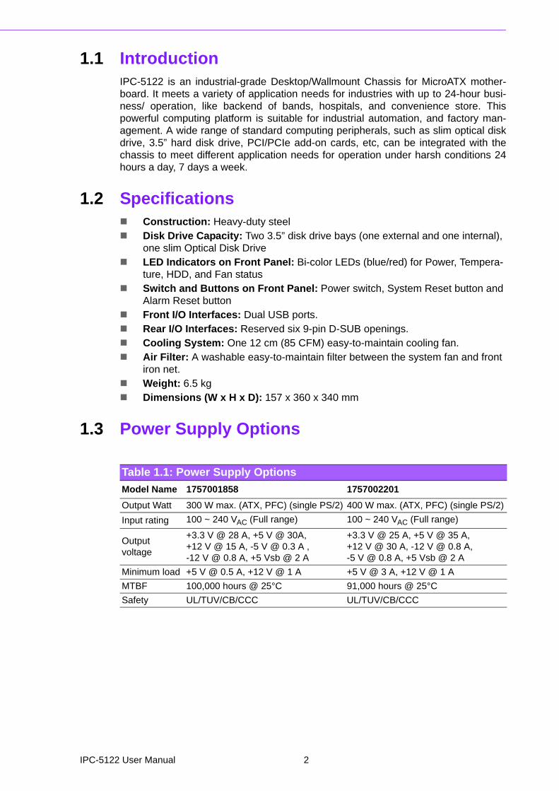
1.1 IntroductionIPC-5122 is an industrial-grade Desktop/Wallmount Chassis for MicroATX mother-board. It meets a variety of application needs for industries with up to 24-hour busi-ness/ operation, like backend of bands, hospitals, and convenience store. Thispowerful computing platform is suitable for industrial automation, and factory man-agement. A wide range of standard computing peripherals, such as slim optical diskdrive, 3.5” hard disk drive, PCI/PCIe add-on cards, etc, can be integrated with thechassis to meet different application needs for operation under harsh conditions 24hours a day, 7 days a week.
1.2 Specifications Construction: Heavy-duty steelDisk Drive Capacity: Two 3.5” disk drive bays (one external and one internal), one slim Optical Disk DriveLED Indicators on Front Panel: Bi-color LEDs (blue/red) for Power, Tempera-ture, HDD, and Fan statusSwitch and Buttons on Front Panel: Power switch, System Reset button and Alarm Reset buttonFront I/O Interfaces: Dual USB ports. Rear I/O Interfaces: Reserved six 9-pin D-SUB openings. Cooling System: One 12 cm (85 CFM) easy-to-maintain cooling fan.Air Filter: A washable easy-to-maintain filter between the system fan and front iron net.Weight: 6.5 kgDimensions (W x H x D): 157 x 360 x 340 mm
1.3 Power Supply Options
Table 1.1: Power Supply Options Model Name 1757001858 1757002201Output Watt 300 W max. (ATX, PFC) (single PS/2) 400 W max. (ATX, PFC) (single PS/2)Input rating 100 ~ 240 VAC (Full range) 100 ~ 240 VAC (Full range)
Output voltage
+3.3 V @ 28 A, +5 V @ 30A,+12 V @ 15 A, -5 V @ 0.3 A ,-12 V @ 0.8 A, +5 Vsb @ 2 A
+3.3 V @ 25 A, +5 V @ 35 A,+12 V @ 30 A, -12 V @ 0.8 A,-5 V @ 0.8 A, +5 Vsb @ 2 A
Minimum load +5 V @ 0.5 A, +12 V @ 1 A +5 V @ 3 A, +12 V @ 1 AMTBF 100,000 hours @ 25°C 91,000 hours @ 25°CSafety UL/TUV/CB/CCC UL/TUV/CB/CCC
IPC-5122 User Manual 2
Chapter 1
GeneralInform
ation
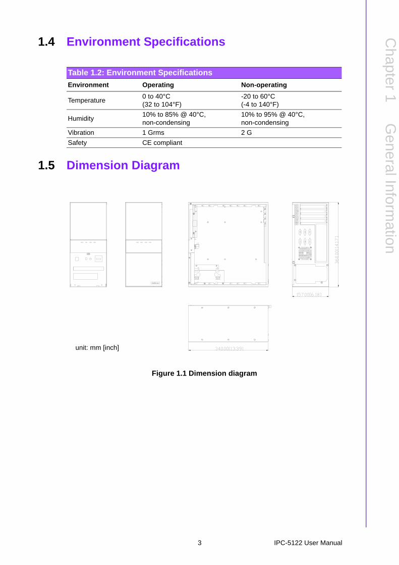
1.4 Environment Specifications
1.5 Dimension Diagram
Figure 1.1 Dimension diagram
Table 1.2: Environment SpecificationsEnvironment Operating Non-operating
Temperature 0 to 40°C (32 to 104°F)
-20 to 60°C (-4 to 140°F)
Humidity 10% to 85% @ 40°C, non-condensing
10% to 95% @ 40°C, non-condensing
Vibration 1 Grms 2 GSafety CE compliant
unit: mm [inch]
3 IPC-5122 User Manual
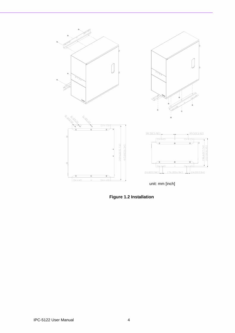
Figure 1.2 Installation
unit: mm [inch]
IPC-5122 User Manual 4
Chapter 2
2 System SetupThis chapter introduces the instal-lation process.Sections include:Removing the Side CoverInstalling MicroATX Mother-boardInstalling Add-on CardInstalling Disk DrivesInstalling Wallmount Bracket
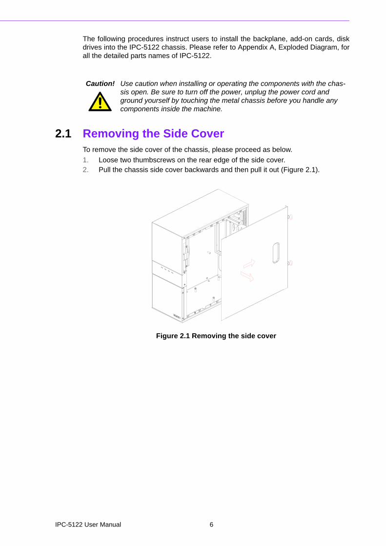
The following procedures instruct users to install the backplane, add-on cards, diskdrives into the IPC-5122 chassis. Please refer to Appendix A, Exploded Diagram, forall the detailed parts names of IPC-5122.
2.1 Removing the Side CoverTo remove the side cover of the chassis, please proceed as below.1. Loose two thumbscrews on the rear edge of the side cover.2. Pull the chassis side cover backwards and then pull it out (Figure 2.1).
Figure 2.1 Removing the side cover
Caution! Use caution when installing or operating the components with the chas-sis open. Be sure to turn off the power, unplug the power cord and ground yourself by touching the metal chassis before you handle any components inside the machine.
IPC-5122 User Manual 6
Chapter 2
System
Setup
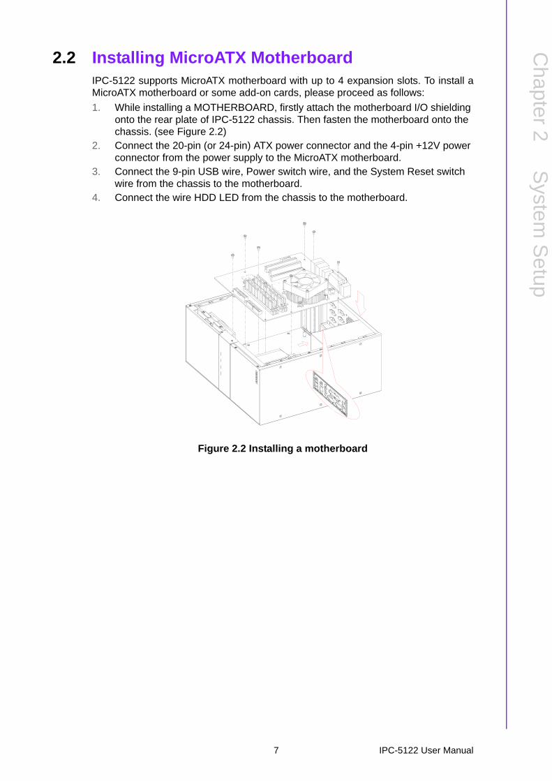
2.2 Installing MicroATX Motherboard IPC-5122 supports MicroATX motherboard with up to 4 expansion slots. To install aMicroATX motherboard or some add-on cards, please proceed as follows:1. While installing a MOTHERBOARD, firstly attach the motherboard I/O shielding
onto the rear plate of IPC-5122 chassis. Then fasten the motherboard onto the chassis. (see Figure 2.2)
2. Connect the 20-pin (or 24-pin) ATX power connector and the 4-pin +12V power connector from the power supply to the MicroATX motherboard.
3. Connect the 9-pin USB wire, Power switch wire, and the System Reset switch wire from the chassis to the motherboard.
4. Connect the wire HDD LED from the chassis to the motherboard.
Figure 2.2 Installing a motherboard
7 IPC-5122 User Manual
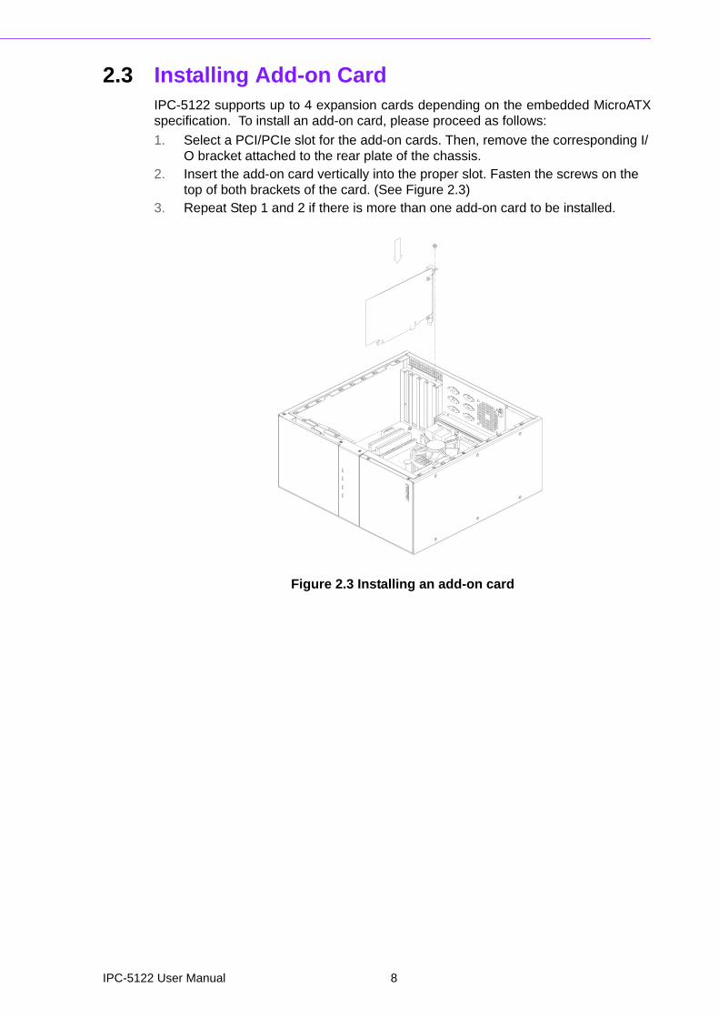
2.3 Installing Add-on Card IPC-5122 supports up to 4 expansion cards depending on the embedded MicroATXspecification. To install an add-on card, please proceed as follows:1. Select a PCI/PCIe slot for the add-on cards. Then, remove the corresponding I/
O bracket attached to the rear plate of the chassis.2. Insert the add-on card vertically into the proper slot. Fasten the screws on the
top of both brackets of the card. (See Figure 2.3)3. Repeat Step 1 and 2 if there is more than one add-on card to be installed.
Figure 2.3 Installing an add-on card
IPC-5122 User Manual 8
Chapter 2
System
Setup
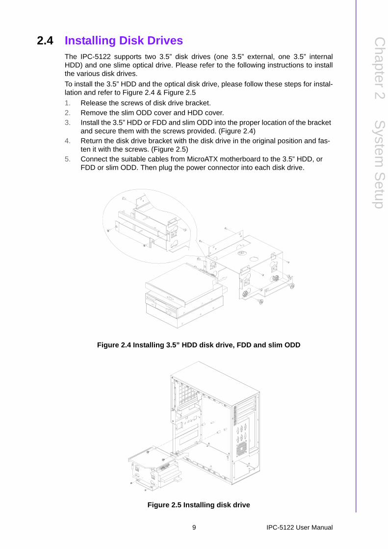
2.4 Installing Disk Drives The IPC-5122 supports two 3.5” disk drives (one 3.5” external, one 3.5” internalHDD) and one slime optical drive. Please refer to the following instructions to installthe various disk drives. To install the 3.5” HDD and the optical disk drive, please follow these steps for instal-lation and refer to Figure 2.4 & Figure 2.51. Release the screws of disk drive bracket.2. Remove the slim ODD cover and HDD cover.3. Install the 3.5” HDD or FDD and slim ODD into the proper location of the bracket
and secure them with the screws provided. (Figure 2.4)4. Return the disk drive bracket with the disk drive in the original position and fas-
ten it with the screws. (Figure 2.5)5. Connect the suitable cables from MicroATX motherboard to the 3.5” HDD, or
FDD or slim ODD. Then plug the power connector into each disk drive.
Figure 2.4 Installing 3.5” HDD disk drive, FDD and slim ODD
Figure 2.5 Installing disk drive
9 IPC-5122 User Manual
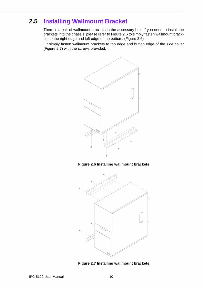
2.5 Installing Wallmount Bracket There is a pair of wallmount brackets in the accessory box. If you need to install thebrackets into the chassis, please refer to Figure 2.6 to simply fasten wallmount brack-ets to the right edge and left edge of the bottom. (Figure 2.6)Or simply fasten wallmount brackets to top edge and button edge of the side cover(Figure 2.7) with the screws provided.
Figure 2.6 Installing wallmount brackets
Figure 2.7 Installing wallmount brackets
IPC-5122 User Manual 10

Chapter 3
3 OperationThis chapter introduces the sys-tem operation information.Sections include:The Front PanelThe Real PanelReplacing the Cooling FanCleaning the FiltersReplacing the Power Supply
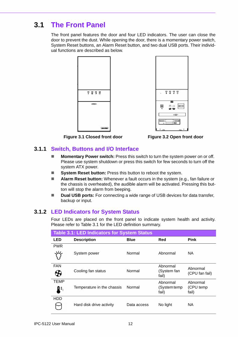
3.1 The Front PanelThe front panel features the door and four LED indicators. The user can close thedoor to prevent the dust. While opening the door, there is a momentary power switch,System Reset buttons, an Alarm Reset button, and two dual USB ports. Their individ-ual functions are described as below.
3.1.1 Switch, Buttons and I/O InterfaceMomentary Power switch: Press this switch to turn the system power on or off. Please use system shutdown or press this switch for few seconds to turn off the system ATX power.System Reset button: Press this button to reboot the system.Alarm Reset button: Whenever a fault occurs in the system (e.g., fan failure or the chassis is overheated), the audible alarm will be activated. Pressing this but-ton will stop the alarm from beeping.Dual USB ports: For connecting a wide range of USB devices for data transfer, backup or input.
3.1.2 LED Indicators for System StatusFour LEDs are placed on the front panel to indicate system health and activity.Please refer to Table 3.1 for the LED definition summary.
Figure 3.1 Closed front door Figure 3.2 Open front door
Table 3.1: LED Indicators for System StatusLED Description Blue Red PinkPWR
System power Normal Abnormal NA
FANCooling fan status Normal
Abnormal (System fan fail)
Abnormal (CPU fan fail)
TEMPTemperature in the chassis Normal
Abnormal (System temp fail)
Abnormal (CPU temp fail)
HDDHard disk drive activity Data access No light NA
IPC-5122 User Manual 12
Chapter 3
Operation
When the system power is on, the power LED is always BLUE.When the system power LED is RED, it indicates a failure of power supply. To stopthe alarm beep, press the Alarm Reset button. Examine the power supply right awayand replace the failed power supply with a good one. When the fan LED is RED, it indicates a failed system fan, and the alarm is activated.When the fan LED is PINK, it indicates a failed CPU cooler and the alarm is also acti-vated. To stop the alarm beep, press the Alarm Reset button and then replace thefailed fan with a good one If the temperature LED is RED, it means that it is overheated inside of the chassis(more than 50°C). And if the temperature LED is PINK, it means that it is overheatedon the CPU card (more than 65°C). An audible alarm will be activated. To stop thealarm beep, press the Alarm Reset button. Inspect the fan filter or temperature ofCPU card and the upper section of the chassis immediately. Make sure the airflowinside the chassis is smooth and not blocked by dust or other particles.
When HDD LED is BLINKING, it indicates the data access from HDD. And whenHDD LED is NO LIGHT, it indicates no activity from HDD.
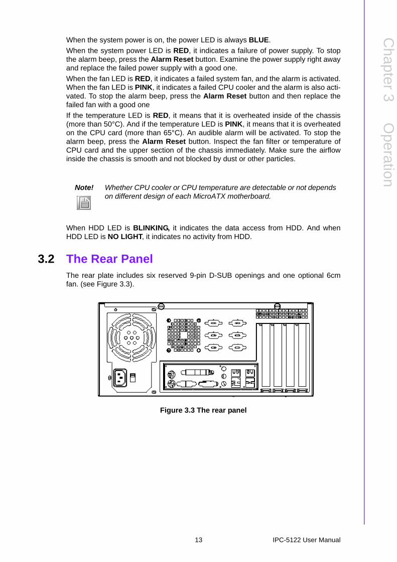
3.2 The Rear PanelThe rear plate includes six reserved 9-pin D-SUB openings and one optional 6cmfan. (see Figure 3.3).
Figure 3.3 The rear panel
Note! Whether CPU cooler or CPU temperature are detectable or not depends on different design of each MicroATX motherboard.
13 IPC-5122 User Manual
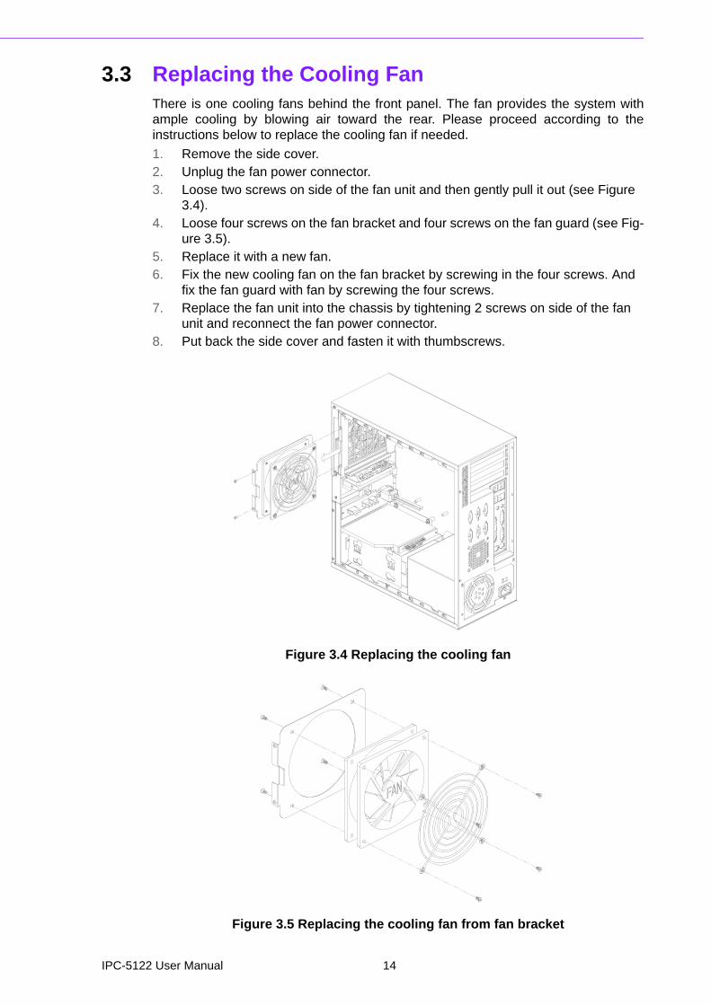
3.3 Replacing the Cooling Fan There is one cooling fans behind the front panel. The fan provides the system withample cooling by blowing air toward the rear. Please proceed according to theinstructions below to replace the cooling fan if needed.1. Remove the side cover.2. Unplug the fan power connector.3. Loose two screws on side of the fan unit and then gently pull it out (see Figure
3.4).4. Loose four screws on the fan bracket and four screws on the fan guard (see Fig-
ure 3.5).5. Replace it with a new fan. 6. Fix the new cooling fan on the fan bracket by screwing in the four screws. And
fix the fan guard with fan by screwing the four screws. 7. Replace the fan unit into the chassis by tightening 2 screws on side of the fan
unit and reconnect the fan power connector.8. Put back the side cover and fasten it with thumbscrews.
Figure 3.4 Replacing the cooling fan
Figure 3.5 Replacing the cooling fan from fan bracket
IPC-5122 User Manual 14
Chapter 3
Operation
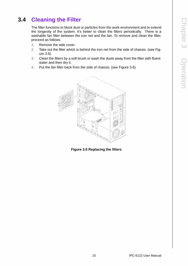
3.4 Cleaning the Filter The filter functions to block dust or particles from the work environment and to extendthe longevity of the system. It’s better to clean the filters periodically. There is awashable fan filter between the iron net and the fan. To remove and clean the filter,proceed as follows.1. Remove the side cover.2. Take out the filter which is behind the iron net from the side of chassis. (see Fig-
ure 3.6)3. Clean the filters by a soft brush or wash the dusts away from the filter with fluent
water and then dry it. 4. Put the fan filter back from the side of chassis. (see Figure 3.6)
Figure 3.6 Replacing the filters
15 IPC-5122 User Manual
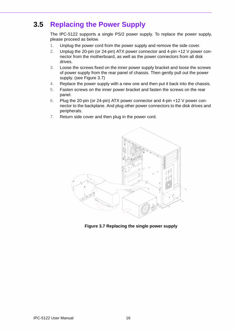
3.5 Replacing the Power Supply The IPC-5122 supports a single PS/2 power supply. To replace the power supply,please proceed as below.1. Unplug the power cord from the power supply and remove the side cover.2. Unplug the 20-pin (or 24-pin) ATX power connector and 4-pin +12 V power con-
nector from the motherboard, as well as the power connectors from all disk drives.
3. Loose the screws fixed on the inner power supply bracket and loose the screws of power supply from the rear panel of chassis. Then gently pull out the power supply. (see Figure 3.7)
4. Replace the power supply with a new one and then put it back into the chassis. 5. Fasten screws on the inner power bracket and fasten the screws on the rear
panel. 6. Plug the 20-pin (or 24-pin) ATX power connector and 4-pin +12 V power con-
nector to the backplane. And plug other power connectors to the disk drives and peripherals.
7. Return side cover and then plug in the power cord.
Figure 3.7 Replacing the single power supply
IPC-5122 User Manual 16
Chapter 4
4 Alarm BoardThis chapter introduces the alarm board and thermal sensor specifi-cations.Sections include:Alarm Board LayoutAlarm Board SpecificationsThermal SensorSensor I.D. Number Setting
The alarm board is located behind the cooling fan near the middle section. The alarmboard makes an audible alarm when:
The ATX power supply fails One of the cooling fans fai1sInternal temperature of the chassis is too highOne of hard drive transmits data
To stop the alarm beep, simply press the Alarm Reset button on the front panelbehind the front door and then take the necessary action to fix it.
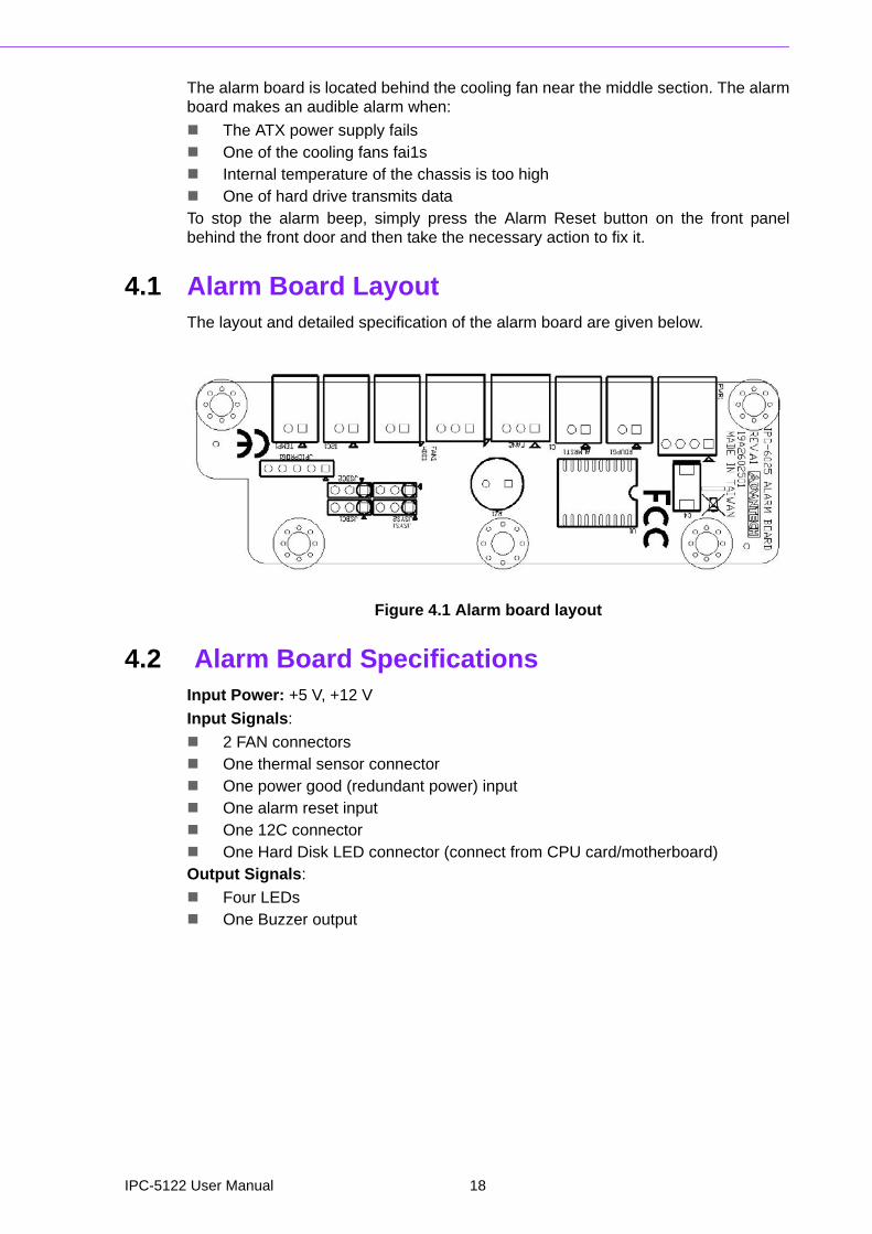
4.1 Alarm Board LayoutThe layout and detailed specification of the alarm board are given below.
Figure 4.1 Alarm board layout
4.2 Alarm Board SpecificationsInput Power: +5 V, +12 VInput Signals:
2 FAN connectorsOne thermal sensor connectorOne power good (redundant power) inputOne alarm reset inputOne 12C connectorOne Hard Disk LED connector (connect from CPU card/motherboard)
Output Signals: Four LEDs One Buzzer output
IPC-5122 User Manual 18
Chapter 4
Alarm
Board
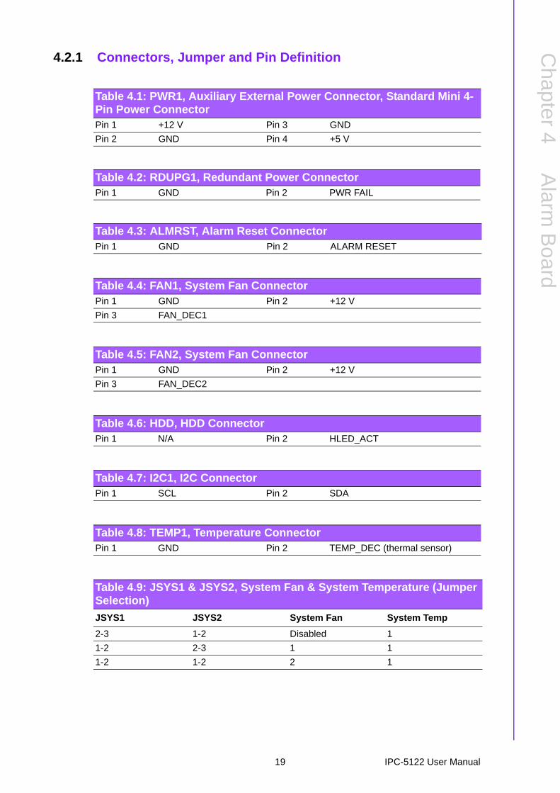
4.2.1 Connectors, Jumper and Pin Definition
Table 4.1: PWR1, Auxiliary External Power Connector, Standard Mini 4-Pin Power ConnectorPin 1 +12 V Pin 3 GNDPin 2 GND Pin 4 +5 V
Table 4.2: RDUPG1, Redundant Power ConnectorPin 1 GND Pin 2 PWR FAIL
Table 4.3: ALMRST, Alarm Reset ConnectorPin 1 GND Pin 2 ALARM RESET
Table 4.4: FAN1, System Fan ConnectorPin 1 GND Pin 2 +12 VPin 3 FAN_DEC1
Table 4.5: FAN2, System Fan ConnectorPin 1 GND Pin 2 +12 VPin 3 FAN_DEC2
Table 4.6: HDD, HDD ConnectorPin 1 N/A Pin 2 HLED_ACT
Table 4.7: I2C1, I2C ConnectorPin 1 SCL Pin 2 SDA
Table 4.8: TEMP1, Temperature ConnectorPin 1 GND Pin 2 TEMP_DEC (thermal sensor)
Table 4.9: JSYS1 & JSYS2, System Fan & System Temperature (Jumper Selection)JSYS1 JSYS2 System Fan System Temp2-3 1-2 Disabled 11-2 2-3 1 11-2 1-2 2 1
19 IPC-5122 User Manual
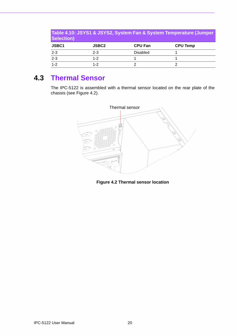
4.3 Thermal Sensor The IPC-5122 is assembled with a thermal sensor located on the rear plate of thechassis (see Figure 4.2).
Figure 4.2 Thermal sensor location
Table 4.10: JSYS1 & JSYS2, System Fan & System Temperature (Jumper Selection)JSBC1 JSBC2 CPU Fan CPU Temp2-3 2-3 Disabled 12-3 1-2 1 11-2 1-2 2 2
Thermal sensor
IPC-5122 User Manual 20

Appendix A
A Exploded Diagram & Parts List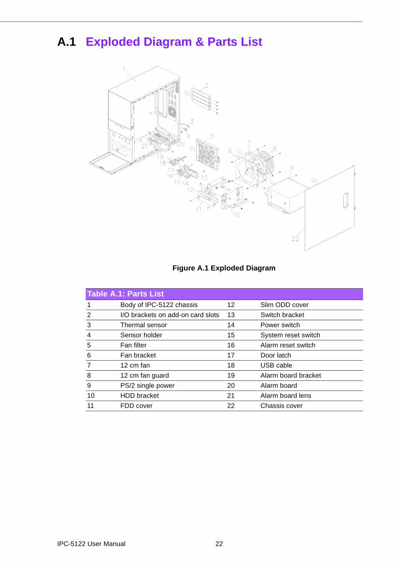
A.1 Exploded Diagram & Parts List
Figure A.1 Exploded Diagram
Table A.1: Parts List1 Body of IPC-5122 chassis 12 Slim ODD cover2 I/O brackets on add-on card slots 13 Switch bracket3 Thermal sensor 14 Power switch4 Sensor holder 15 System reset switch5 Fan filter 16 Alarm reset switch6 Fan bracket 17 Door latch7 12 cm fan 18 USB cable8 12 cm fan guard 19 Alarm board bracket9 PS/2 single power 20 Alarm board 10 HDD bracket 21 Alarm board lens11 FDD cover 22 Chassis cover
1
2
3
4 5
87
6
9
22
1011
121415
16 13
17
1819
2021
IPC-5122 User Manual 22

Appendix B
B Motherboard Options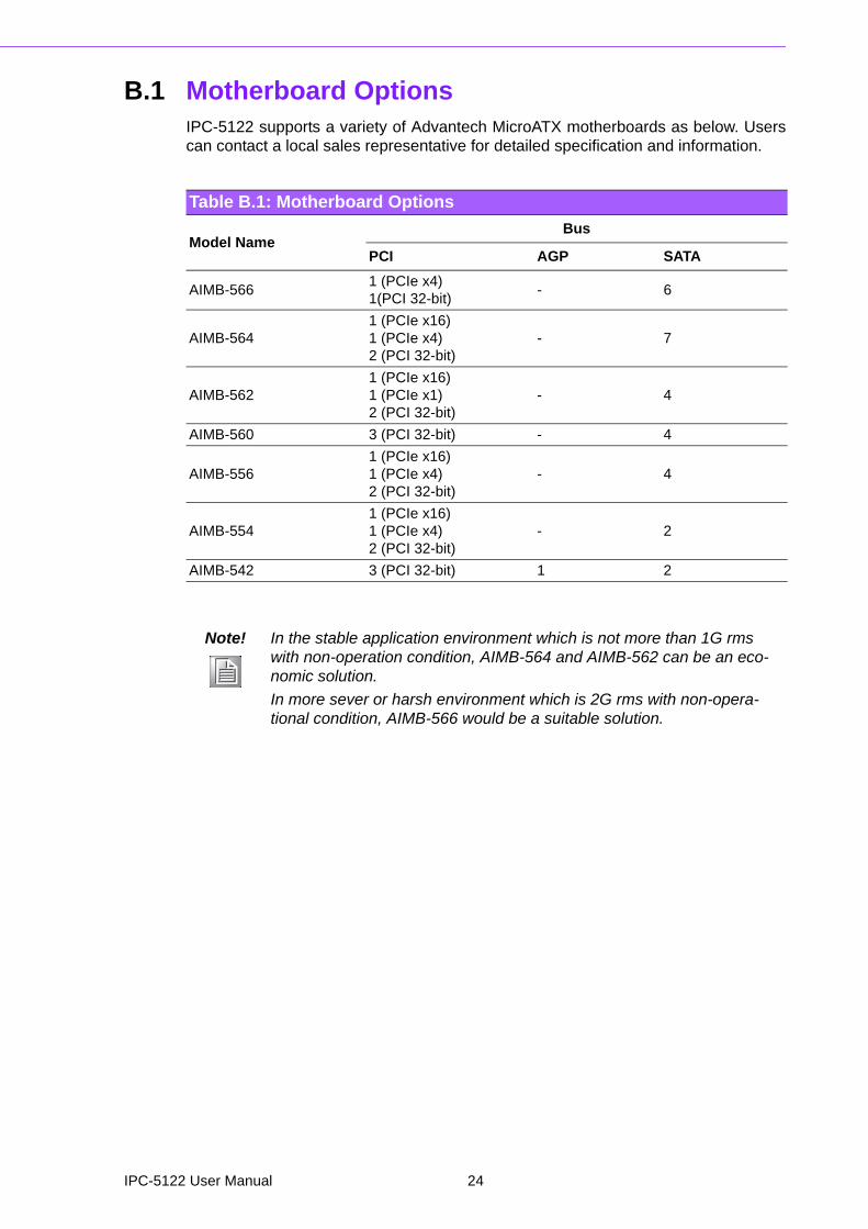
B.1 Motherboard OptionsIPC-5122 supports a variety of Advantech MicroATX motherboards as below. Userscan contact a local sales representative for detailed specification and information.
Table B.1: Motherboard Options
Model NameBus
PCI AGP SATA
AIMB-566 1 (PCIe x4)1(PCI 32-bit) - 6
AIMB-5641 (PCIe x16)1 (PCIe x4)2 (PCI 32-bit)
- 7
AIMB-5621 (PCIe x16)1 (PCIe x1)2 (PCI 32-bit)
- 4
AIMB-560 3 (PCI 32-bit) - 4
AIMB-5561 (PCIe x16)1 (PCIe x4)2 (PCI 32-bit)
- 4
AIMB-5541 (PCIe x16)1 (PCIe x4)2 (PCI 32-bit)
- 2
AIMB-542 3 (PCI 32-bit) 1 2
Note! In the stable application environment which is not more than 1G rms with non-operation condition, AIMB-564 and AIMB-562 can be an eco-nomic solution.In more sever or harsh environment which is 2G rms with non-opera-tional condition, AIMB-566 would be a suitable solution.
IPC-5122 User Manual 24

Appendix B
Motherboard
Options
25 IPC-5122 User Manual

www.advantech.comPlease verify specifications before quoting. This guide is intended for referencepurposes only.All product specifications are subject to change without notice.No part of this publication may be reproduced in any form or by any means,electronic, photocopying, recording or otherwise, without prior written permis-sion of the publisher.All brand and product names are trademarks or registered trademarks of theirrespective companies.© Advantech Co., Ltd. 2009