Embed Size (px)
Citation preview
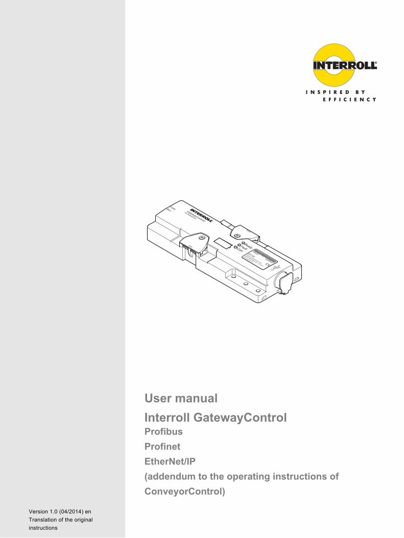
User manual
Interroll GatewayControlProfibus
Profinet
EtherNet/IP
(addendum to the operating instructions of
ConveyorControl)Chapter-ID: User manualChapter-ID: VersionChapter-ID: Translation of the original instructions
Version 1.0 (04/2014) en
Translation of the original
instructions

Manufacturer's addressInterroll Engineering GmbH Hoeferhof 16D-42929 WermelskirchenTel. +49 2193 23 0Fax. +49 2190 2022www.interroll.com
CopyrightThe copyright of this manual remains with Interroll Engineering GmbH. The operating instructions contain technical regulations and drawings which may not be reproduced partially or in full, transmitted by any means, utilized without permission for competitive purposes or disclosed to third parties.
Version 1.0 (04/2014) en
Translation of the original instructions
GatewayControl
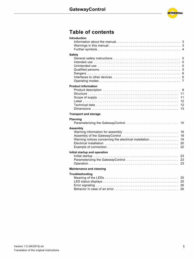
Table of contentsIntroduction
Information about the manual . . . . . . . . . . . . . . . . . . . . . . . . . . . . . . . . . . . 3Warnings in this manual . . . . . . . . . . . . . . . . . . . . . . . . . . . . . . . . . . . . . . . 3Further symbols . . . . . . . . . . . . . . . . . . . . . . . . . . . . . . . . . . . . . . . . . . . . . 4
SafetyGeneral safety instructions. . . . . . . . . . . . . . . . . . . . . . . . . . . . . . . . . . . . . 5Intended use . . . . . . . . . . . . . . . . . . . . . . . . . . . . . . . . . . . . . . . . . . . . . . . 5Unintended use . . . . . . . . . . . . . . . . . . . . . . . . . . . . . . . . . . . . . . . . . . . . . 5Qualified persons . . . . . . . . . . . . . . . . . . . . . . . . . . . . . . . . . . . . . . . . . . . . 5Dangers . . . . . . . . . . . . . . . . . . . . . . . . . . . . . . . . . . . . . . . . . . . . . . . . . . . 6Interfaces to other devices . . . . . . . . . . . . . . . . . . . . . . . . . . . . . . . . . . . . . 6Operating modes . . . . . . . . . . . . . . . . . . . . . . . . . . . . . . . . . . . . . . . . . . . . 7
Product informationProduct description . . . . . . . . . . . . . . . . . . . . . . . . . . . . . . . . . . . . . . . . . . 8Structure . . . . . . . . . . . . . . . . . . . . . . . . . . . . . . . . . . . . . . . . . . . . . . . . . 11Scope of supply . . . . . . . . . . . . . . . . . . . . . . . . . . . . . . . . . . . . . . . . . . . . 11Label . . . . . . . . . . . . . . . . . . . . . . . . . . . . . . . . . . . . . . . . . . . . . . . . . . . . 12Technical data . . . . . . . . . . . . . . . . . . . . . . . . . . . . . . . . . . . . . . . . . . . . . 12Dimensions . . . . . . . . . . . . . . . . . . . . . . . . . . . . . . . . . . . . . . . . . . . . . . . 13
Transport and storage
PlanningParameterizing the GatewayControl . . . . . . . . . . . . . . . . . . . . . . . . . . . . . 15
AssemblyWarning information for assembly . . . . . . . . . . . . . . . . . . . . . . . . . . . . . . 18Assembly of the GatewayControl . . . . . . . . . . . . . . . . . . . . . . . . . . . . . . . 18Warning notices concerning the electrical installation. . . . . . . . . . . . . . . . 19Electrical installation . . . . . . . . . . . . . . . . . . . . . . . . . . . . . . . . . . . . . . . . 20Example of connection . . . . . . . . . . . . . . . . . . . . . . . . . . . . . . . . . . . . . . . 22
Initial startup and operationInitial startup . . . . . . . . . . . . . . . . . . . . . . . . . . . . . . . . . . . . . . . . . . . . . . 23Parameterizing the GatewayControl . . . . . . . . . . . . . . . . . . . . . . . . . . . . . 23Operation . . . . . . . . . . . . . . . . . . . . . . . . . . . . . . . . . . . . . . . . . . . . . . . . . 23
Maintenance and cleaning
TroubleshootingMeaning of the LEDs . . . . . . . . . . . . . . . . . . . . . . . . . . . . . . . . . . . . . . . . 25LED status displays . . . . . . . . . . . . . . . . . . . . . . . . . . . . . . . . . . . . . . . . . 25Error signaling . . . . . . . . . . . . . . . . . . . . . . . . . . . . . . . . . . . . . . . . . . . . . 26Behavior in case of an error . . . . . . . . . . . . . . . . . . . . . . . . . . . . . . . . . . . 26
1Version 1.0 (04/2014) en
Translation of the original instructions
GatewayControl
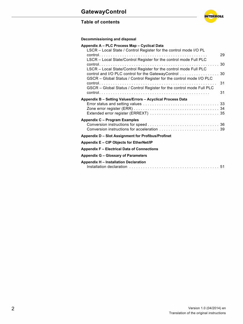
Table of contents
Decommissioning and disposal
Appendix A – PLC Process Map – Cyclical DataLSCR – Local State / Control Register for the control mode I/O PLcontrol . . . . . . . . . . . . . . . . . . . . . . . . . . . . . . . . . . . . . . . . . . . . . . . 29LSCR – Local State/Control Register for the control mode Full PLCcontrol . . . . . . . . . . . . . . . . . . . . . . . . . . . . . . . . . . . . . . . . . . . . . . . . . . . . 30LSCR – Local State/Control Register for the control mode Full PLCcontrol and I/O PLC control for the GatewayControl . . . . . . . . . . . . . . . . . 30GSCR – Global Status / Control Register for the control mode I/O PLCcontrol . . . . . . . . . . . . . . . . . . . . . . . . . . . . . . . . . . . . . . . . . . . . . . . . . . . 31GSCR – Global Status / Control Register for the control mode Full PLCcontrol . . . . . . . . . . . . . . . . . . . . . . . . . . . . . . . . . . . . . . . . . . . . . . . . 31
Appendix B – Setting Values/Errors – Acyclical Process DataError status and setting values . . . . . . . . . . . . . . . . . . . . . . . . . . . . . . . . . 33Zone error register (ERR) . . . . . . . . . . . . . . . . . . . . . . . . . . . . . . . . . . . . . 34Extended error register (ERREXT) . . . . . . . . . . . . . . . . . . . . . . . . . . . . . . 35
Appendix C – Program ExamplesConversion instructions for speed . . . . . . . . . . . . . . . . . . . . . . . . . . . . . . . 36Conversion instructions for acceleration . . . . . . . . . . . . . . . . . . . . . . . . . . 39
Appendix D – Slot Assignment for Profibus/Profinet
Appendix E – CIP Objects for EtherNet/IP
Appendix F – Electrical Data of Connections
Appendix G – Glossary of Parameters
Appendix H – Installation DeclarationInstallation declaration . . . . . . . . . . . . . . . . . . . . . . . . . . . . . . . . . . . . . . . 51
2 Version 1.0 (04/2014) en
Translation of the original instructions
GatewayControl
Introduction
Information about the manual
Contents These operating instructions contain important notes and information about the following topics:• Connection of GatewayControl• Data and error transmission
Details about transport, planning, assembly, commissioning, maintenance and cleaning are located in the operating instructions of the ConveyorControl system.
Other applicable documents: These operating instructions are valid only in conjunction with the following documents:
• ConveyorControl system operating instructions
Validity of the manual The manual describes the GatewayControl as it is delivered by Interroll.
In addition to this manual, special contractual agreements and technical documents apply to special versions.
The manual is part of theproduct
For trouble-free, safe operation and warranty claims, read the manual and follow the instructions before handling the GatewayControl.
Keep the manual near to the GatewayControl. Pass the manual on to any subsequent operator or occupant of the
GatewayControl. Interroll does not accept any liability for faults or defects due to non-
observance of this manual. If you have any questions after reading the operation manual, feel free to
contact our customer service. Contact persons close to you can be found on the Internet under www.interroll.com/contacts.
Warnings in this manual
The warnings in this document refer to risks which may arise while using the GatewayControl. For relevant warnings, see "Safety", page 5 and the warnings at the beginning of each chapter.
There are three categories of danger. The following signal words are used in the document as required:• Danger • Warning• Caution
Signal word Meaning
Danger Indicates a hazardous situation which, if not avoided, will result in death or serious injury.
Warning Indicates a hazardous situation which, if not avoided, could result in death or serious injury.
Caution Indicates a hazardous situation which, if not avoided, may result in minor or moderate injury.
3Version 1.0 (04/2014) en
Translation of the original instructions
GatewayControl
Introduction
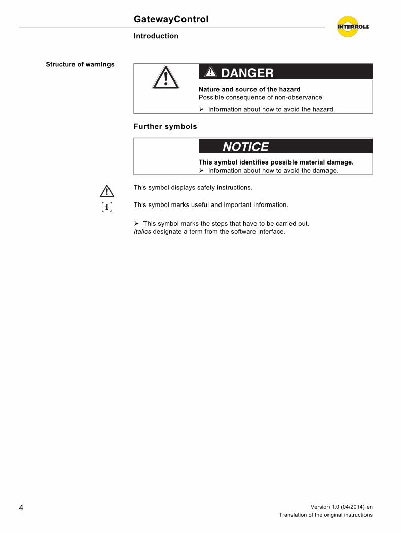
Structure of warnings
Further symbols
This symbol marks the steps that have to be carried out.Italics designate a term from the software interface.
Nature and source of the hazardPossible consequence of non-observance
Information about how to avoid the hazard.
DANGER
This symbol identifies possible material damage. Information about how to avoid the damage.
Important
This symbol displays safety instructions.Hint
This symbol marks useful and important information.
4 Version 1.0 (04/2014) en
Translation of the original instructions
GatewayControl
Safety
General safety instructions
The GatewayControl has been built to comply with the state of the art and is operationally safe in its delivered state. Nevertheless, users may encounter hazards during use:• Risks of physical injury to the user or bystanders• Adverse effects of the GatewayControl and other material.
Always read the entire operating and safety instructions before starting to work with the GatewayControl and follow the information contained therein in full.
Only instructed and qualified persons may work with the GatewayControl. Always keep the user manual at hand when working at the GatewayControl so
you can consult it quickly if required. Always comply with relevant national safety regulations. If you have any questions after reading the operation manual, feel free to
contact our customer service. See the last page for your local contact information.
Intended use
The GatewayControl may only be used for industrial applications and in an industrial environment to control the RollerDrive EC310.
The GatewayControl must be integrated into a conveyor module or conveyor system. Any other use is considered inappropriate.
Any modifications that affect the safety of the product are not permitted.
The GatewayControl may only be operated within the defined operating limits.
Unintended use
Use for anything other than the intended purpose requires approval by Interroll.
Qualified persons
Qualified persons are persons who read and understand the manual and, taking national regulations into account, can competently execute incidental work.
Only trained and qualified persons may work with the ConveyorControl system, taking the following into account:• the relevant manuals and diagrams,• the warning and safety instructions in this manual,• the system specific regulations and requirements,• national or local regulations and requirements for safety and accident
prevention.
Important
Disregarding the warning notices in this manual may lead to serious injury.
5Version 1.0 (04/2014) en
Translation of the original instructions
GatewayControl
Safety
Dangers
Bodily injury Maintenance or repair work must only be performed by authorized and qualified persons in accordance with the applicable regulations.
Before using the GatewayControl, ensure that no unauthorized persons are near the conveyor.
Electricity Only perform installation and maintenance work after you have switched off the power.
Ensure that the power cannot be turned on accidentally.
Working environment Do not use the GatewayControl in areas where there is a hazard of explosion. Remove equipment or material which is not required from the workspace.
Faults during operation Regularly inspect the ConveyorControl components for visible damage. If you notice smoke, switch off the power immediately and ensure that it
cannot be switched on again accidentally. Contact qualified personnel immediately to find the source of the fault.
Maintenance Because the product does not require maintenance, you only need to inspect the ConveyorControl components regularly for visible damage and that all cables and screws are firmly in place.
Accidental motor starts Exercise caution when installing or performing maintenance on the ConveyorControl components and when troubleshooting, as a start signal may accidentally be triggered, unintentionally starting one of the connected motors.
Interfaces to other devices
When assembling the ConveyorControl components in a conveyor, further hazards may occur. These hazards are not part of this manual and have to be analyzed during the design, installation and startup of the conveyor.
After assembling the GatewayControl in a conveyor, check the whole system for new potential dangerous spots before switching on.
Important
The following list provides information about the various types of danger or damage that may occur while working with the GatewayControl.
6 Version 1.0 (04/2014) en
Translation of the original instructions
GatewayControl
Safety
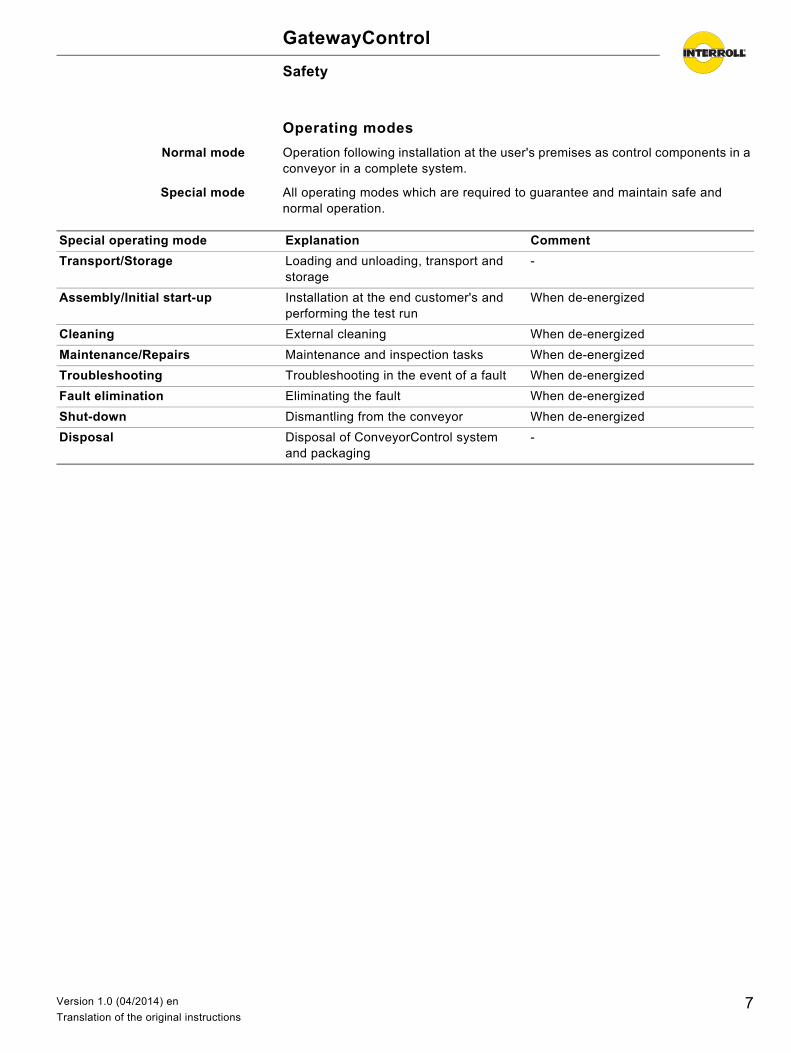
Operating modes
Normal mode Operation following installation at the user's premises as control components in a conveyor in a complete system.
Special mode All operating modes which are required to guarantee and maintain safe and normal operation.
Special operating mode Explanation Comment
Transport/Storage Loading and unloading, transport and storage
-
Assembly/Initial start-up Installation at the end customer's and performing the test run
When de-energized
Cleaning External cleaning When de-energized
Maintenance/Repairs Maintenance and inspection tasks When de-energized
Troubleshooting Troubleshooting in the event of a fault When de-energized
Fault elimination Eliminating the fault When de-energized
Shut-down Dismantling from the conveyor When de-energized
Disposal Disposal of ConveyorControl system and packaging
-
7Version 1.0 (04/2014) en
Translation of the original instructions
GatewayControl
Product information
Product description
The GatewayControl is part of the ConveyorControl system and represents an alternative to the CentralControl. It allows connecting the system to Profibus, Profinet or EtherNet/IP.
The ConveyorControl system consists of the following additional components:• SegmentControl• ComControl• Configurator• Accessories
Details about the additional components are located in the operating instructions of the ConveyorControl system.
GatewayControl The GatewayControl monitors the correct connection and functioning of the individual ConveyorControl modules. It is connected via the bus communication with these modules and can thus recognize and assess various system fault types. The GatewayControl is connected to a master control (PLC) via Profibus, Profinet or EtherNet/IP. It is implemented as IO adapter (slave) and supports implicit (cyclical) and explicit (acyclical) data exchange.
Tasks of the GatewayControl at a glance:• Manage the ConveyorControl system with a maximum of 200 zones and
control their communication• Control central functions such as Empty conveyor or Reversal of direction• Address and parameterize SegmentControl and ComControl• Monitor the ConveyorControl system• Form interface to PLC via Profibus, Profinet or EtherNet/IP
The GatewayControl must be connected to one end of the bus line. It features a terminating resistor which is required for the bus line. A ComControl with activated terminating resistor must be connected to the other end of the bus line.
Control modes A GatewayControl can be operated in two different control modes:• I/O PLC control: In this control mode, SegmentControls and ComControls
control the conveying process. The master PLC can monitor and influence the conveying process using the process map for individual zones or the entire conveyor (start, stop, reversal of direction).
• Full PLC control: In this control mode, the master PLC controls the conveying process. The process map of the PLC shows the current states of the sensors and the RollerDrive and individual RollerDrives can be switched on or off. In this control mode, the ConveyorControl system does not offer a zero pressure accumulation control logic, which must be programmed via the PLC.
Web server The GatewayControl for EtherNet/IP and for Profinet contains a web server which can be used to perform software updates. The Internet or intranet access to the device made possible via the integrated web server also comes with the risk of abuse. Access to the web server is secured with a user ID and a password.
8 Version 1.0 (04/2014) en
Translation of the original instructions
GatewayControl
Product information
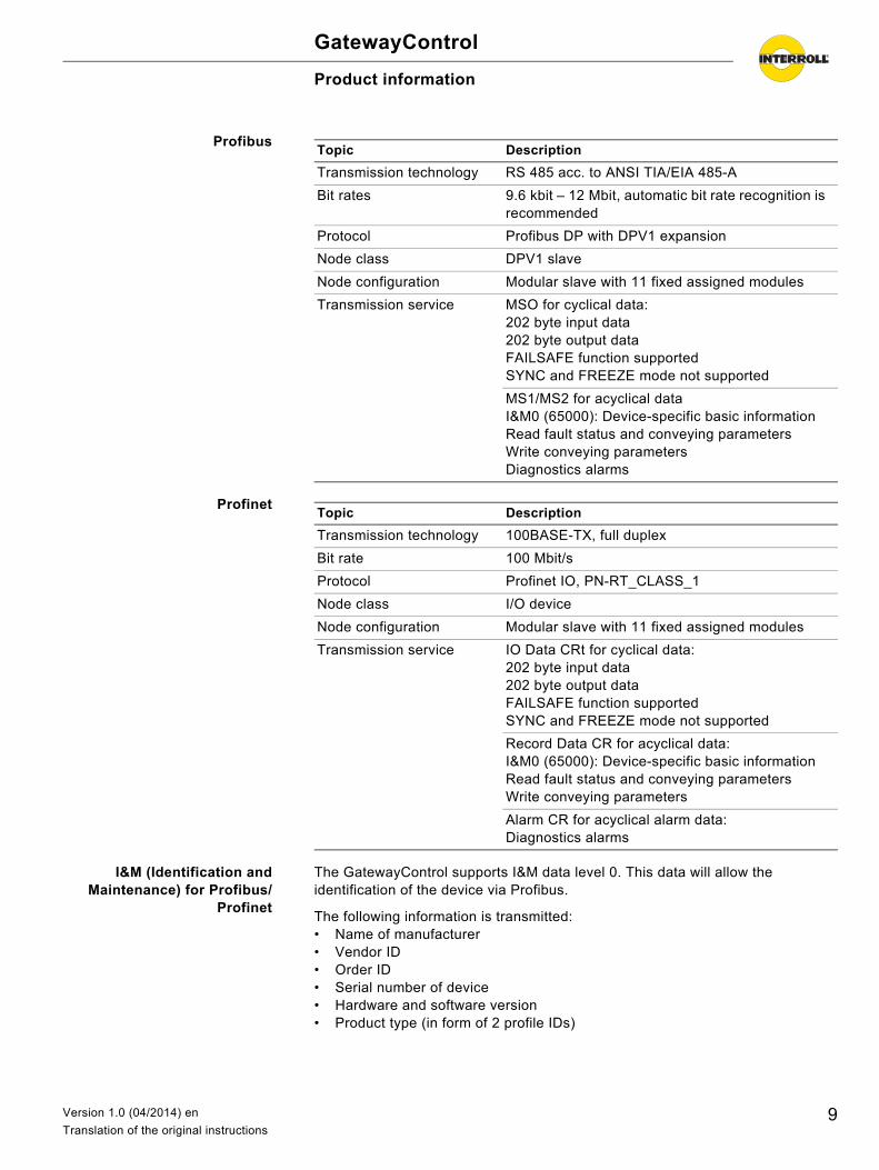
Profibus
Profinet
I&M (Identification andMaintenance) for Profibus/
Profinet
The GatewayControl supports I&M data level 0. This data will allow the identification of the device via Profibus.
The following information is transmitted:• Name of manufacturer• Vendor ID• Order ID• Serial number of device• Hardware and software version• Product type (in form of 2 profile IDs)
Topic Description
Transmission technology RS 485 acc. to ANSI TIA/EIA 485-A
Bit rates 9.6 kbit – 12 Mbit, automatic bit rate recognition is recommended
Protocol Profibus DP with DPV1 expansion
Node class DPV1 slave
Node configuration Modular slave with 11 fixed assigned modules
Transmission service MSO for cyclical data:202 byte input data202 byte output dataFAILSAFE function supportedSYNC and FREEZE mode not supported
MS1/MS2 for acyclical dataI&M0 (65000): Device-specific basic informationRead fault status and conveying parametersWrite conveying parametersDiagnostics alarms
Topic Description
Transmission technology 100BASE-TX, full duplex
Bit rate 100 Mbit/s
Protocol Profinet IO, PN-RT_CLASS_1
Node class I/O device
Node configuration Modular slave with 11 fixed assigned modules
Transmission service IO Data CRt for cyclical data:202 byte input data202 byte output dataFAILSAFE function supportedSYNC and FREEZE mode not supported
Record Data CR for acyclical data:I&M0 (65000): Device-specific basic informationRead fault status and conveying parametersWrite conveying parameters
Alarm CR for acyclical alarm data:Diagnostics alarms
9Version 1.0 (04/2014) en
Translation of the original instructions
GatewayControl
Product information
Diagnostics and alarms forProfibus/Profinet
The GatewayControl provides an expanded diagnostics according to the Profibus/Profinet standard.
The manufacturer-specific diagnostics data consist of 4 bytes with the following content:• 2 bytes, global error register (ERR)• 2 bytes, extended error register (ERR_EXT)
The content of the ERR and ERR_EXT register is described in (see "Error status and setting values", page 33).
The slot assignment for the data modules is described in appendix D (see page 42).
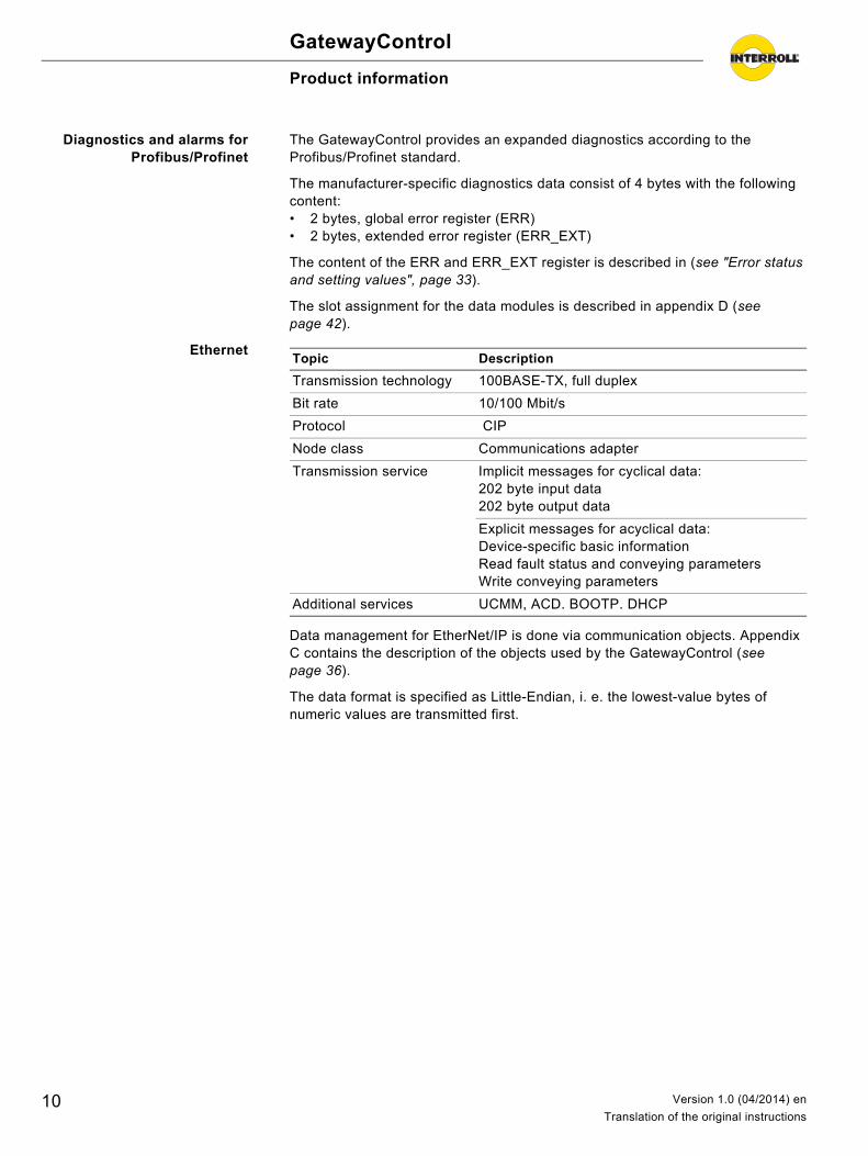
Ethernet
Data management for EtherNet/IP is done via communication objects. Appendix C contains the description of the objects used by the GatewayControl (see page 36).
The data format is specified as Little-Endian, i. e. the lowest-value bytes of numeric values are transmitted first.
Topic Description
Transmission technology 100BASE-TX, full duplex
Bit rate 10/100 Mbit/s
Protocol CIP
Node class Communications adapter
Transmission service Implicit messages for cyclical data:202 byte input data202 byte output data
Explicit messages for acyclical data:Device-specific basic informationRead fault status and conveying parametersWrite conveying parameters
Additional services UCMM, ACD. BOOTP. DHCP
10 Version 1.0 (04/2014) en
Translation of the original instructions
GatewayControl
Product information
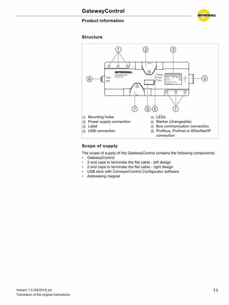
Structure
Scope of supply
The scope of supply of the GatewayControl contains the following components:• GatewayControl• 2 end caps to terminate the flat cable - left design• 2 end caps to terminate the flat cable - right design• USB stick with ConveyorControl Configurator software• Addressing magnet
1 Mounting holes2 Power supply connection3 Label4 USB connection
5 LEDs6 Marker (changeable)7 Bus communication connection8 Profibus, Profinet or EtherNet/IP
connection
11Version 1.0 (04/2014) en
Translation of the original instructions
GatewayControl
Product information
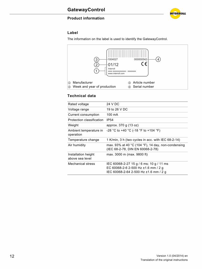
Label
The information on the label is used to identify the GatewayControl.
Technical data
1 Manufacturer2 Week and year of production
3 Article number4 Serial number
xxxx xxxxxxxxxxxxx - xxxxxxxx
Rated voltage 24 V DC
Voltage range 19 to 26 V DC
Current consumption 100 mA
Protection classification IP54
Weight approx. 370 g (13 oz)
Ambient temperature in operation
-28 °C to +40 °C (-18 °F to +104 °F)
Temperature change 1 K/min, 3 h (two cycles in acc. with IEC 68-2-14)
Air humidity max. 93% at 40 °C (104 °F), 14 day, non-condensing (IEC 68-2-78, DIN EN 60068-2-78)
Installation height above sea level
max. 3000 m (max. 9800 ft)
Mechanical stress IEC 60068-2-27 15 g / 6 ms; 10 g / 11 ms EC 60068-2-6 2-500 Hz ±1.6 mm / 2 g IEC 60068-2-64 2-500 Hz ±1.6 mm / 2 g
12 Version 1.0 (04/2014) en
Translation of the original instructions
GatewayControl
Product information
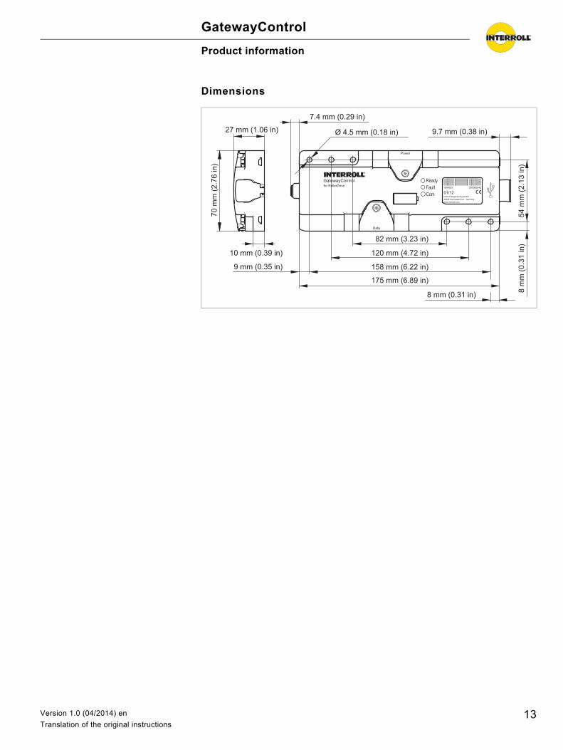
Dimensions
GatewayControl
70 m
m (2
.76
in)
10 mm (0.39 in)
27 mm (1.06 in)
82 mm (3.23 in)
120 mm (4.72 in)
158 mm (6.22 in)
175 mm (6.89 in)
8 mm (0.31 in)
9.7 mm (0.38 in)
54 m
m (2
.13
in)
8 m
m (0
.31
in)
7.4 mm (0.29 in)
9 mm (0.35 in)
Ø 4.5 mm (0.18 in)
13Version 1.0 (04/2014) en
Translation of the original instructions

GatewayControl
Transport and storageDetails about the transport and storage are located in the operating instructions of the ConveyorControl system.
14 Version 1.0 (04/2014) en
Translation of the original instructions
GatewayControl
PlanningThe planning of a ConveyorControl system with GatewayControl is done with the ConveyorControl Configurator (henceforth referred to solely as Configurator). All the module parameters can be set offline and then downloaded collectively to the ConveyorControl modules.
The following steps are required for this purpose:• Map: Map the zones of the conveyor path and all ConveyorControl modules
with the Configurator• Prepare to address: The assignment of a unique address for each module is
being prepared• Address: Assign modules a unique address suing the addressing magnet• Parameterize: Define settings for each module• Download: Parameters are downloaded to the modules
Details about the Configurator and planning the conveying path with all ConveyorControl modules are located in the operating instructions of the ConveyorControl system.
This chapter contains notes about the parameterization of the GatewayControl.
Parameterizing the GatewayControl
In this step, the settings for the GatewayControl can be defined. They only take effect once they have been downloaded to the module.
Requirement: The conveying path was completely mapped in the Configurator (see operating instructions of the ConveyorControl system).
In the work step bar, click on the Parameterize button. Select GatewayControl. Click on the value of the Control mode parameter and select I/O PLC control
or Full PLC control. Change the parameters according to the requirements.
15Version 1.0 (04/2014) en
Translation of the original instructions
GatewayControl
Planning
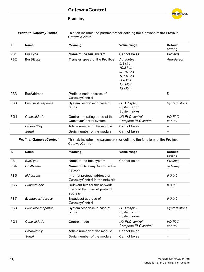
Profibus GatewayControl This tab includes the parameters for defining the functions of the Profibus GatewayControl.
Profinet GatewayControl This tab includes the parameters for defining the functions of the Profinet GatewayControl.
ID Name Meaning Value range Default setting
PB1 BusType Name of the bus system Cannot be set Profibus
PB2 BusBitrate Transfer speed of the Profibus Autodetect9.6 kbit19.2 kbit93.75 kbit187.5 kbit500 kbit1.5 Mbit12 Mbit
Autodetect
PB3 BusAddress Profibus node address of GatewayControl
5
PB8 BusErrorResponse System response in case of faults
LED displaySystem errorSystem stops
System stops
PG1 ControlMode Control operating mode of the ConveyorControl system
I/O PLC controlComplete PLC control
I/O PLC control
ProductKey Article number of the module Cannot be set –
Serial Serial number of the module Cannot be set –
ID Name Meaning Value range Default setting
PB1 BusType Name of the bus system Cannot be set Profinet
PB4 HostName Name of GatewayControl in the network
gateway
PB5 IPAddress Internet protocol address of GatewayControl in the network
0.0.0.0
PB6 SubnetMask Relevant bits for the network prefix of the Internet protocol address
0.0.0.0
PB7 BroadcastAddress Broadcast address of GatewayControl
0.0.0.0
PB8 BusErrorResponse System response in case of faults
LED displaySystem errorSystem stops
System stops
PG1 ControlMode Control mode I/O PLC controlComplete PLC control
I/O PLC control.
ProductKey Article number of the module Cannot be set –
Serial Serial number of the module Cannot be set –
16 Version 1.0 (04/2014) en
Translation of the original instructions
GatewayControl
Planning
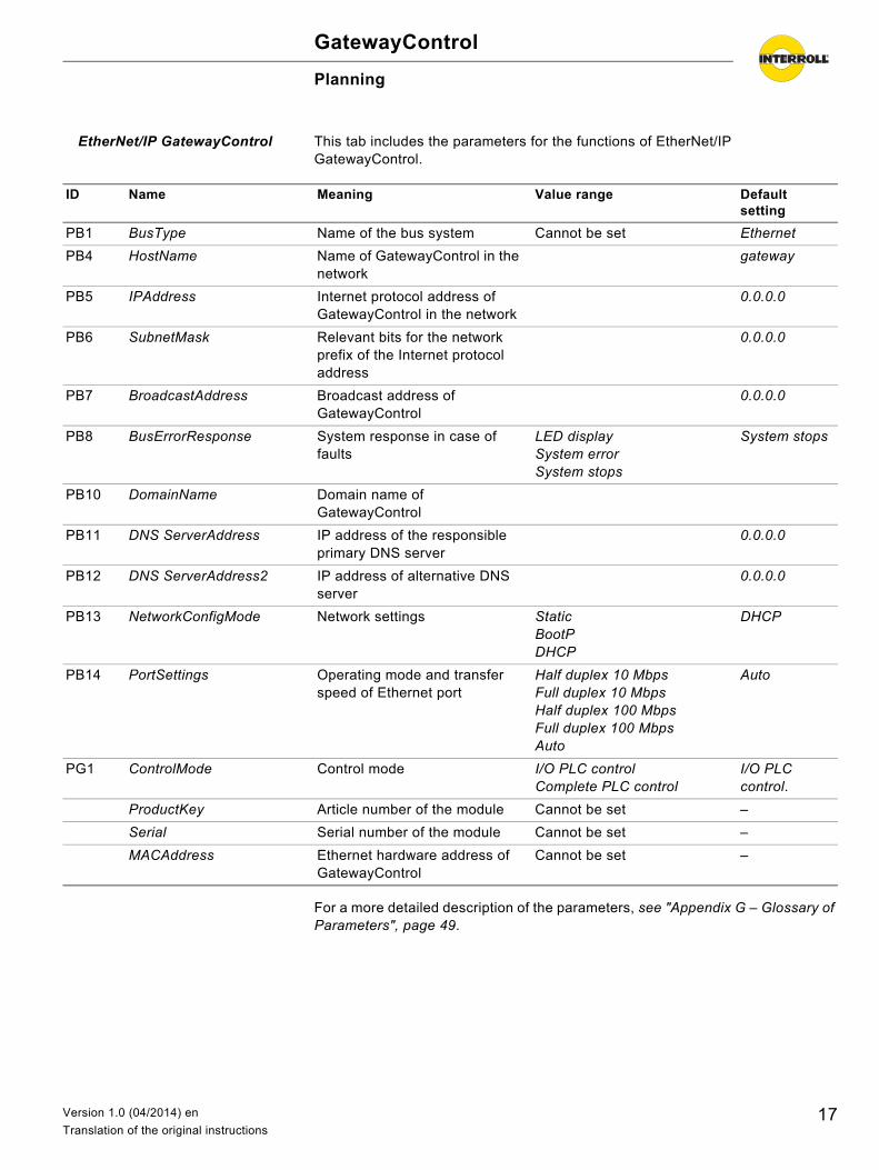
EtherNet/IP GatewayControl This tab includes the parameters for the functions of EtherNet/IP GatewayControl.
For a more detailed description of the parameters, see "Appendix G – Glossary of Parameters", page 49.
ID Name Meaning Value range Default setting
PB1 BusType Name of the bus system Cannot be set Ethernet
PB4 HostName Name of GatewayControl in the network
gateway
PB5 IPAddress Internet protocol address of GatewayControl in the network
0.0.0.0
PB6 SubnetMask Relevant bits for the network prefix of the Internet protocol address
0.0.0.0
PB7 BroadcastAddress Broadcast address of GatewayControl
0.0.0.0
PB8 BusErrorResponse System response in case of faults
LED displaySystem errorSystem stops
System stops
PB10 DomainName Domain name of GatewayControl
PB11 DNS ServerAddress IP address of the responsible primary DNS server
0.0.0.0
PB12 DNS ServerAddress2 IP address of alternative DNS server
0.0.0.0
PB13 NetworkConfigMode Network settings StaticBootPDHCP
DHCP
PB14 PortSettings Operating mode and transfer speed of Ethernet port
Half duplex 10 MbpsFull duplex 10 MbpsHalf duplex 100 MbpsFull duplex 100 MbpsAuto
Auto
PG1 ControlMode Control mode I/O PLC controlComplete PLC control
I/O PLC control.
ProductKey Article number of the module Cannot be set –
Serial Serial number of the module Cannot be set –
MACAddress Ethernet hardware address of GatewayControl
Cannot be set –
17Version 1.0 (04/2014) en
Translation of the original instructions
GatewayControl
Assembly
Warning information for assembly
Assembly of the GatewayControl
For notes about the assembly, see the operating instructions of the ConveyorControl system.
Risk of damage leading to failure or shortened life expectancy Check each GatewayControl module visually for
damage before assembly. Make sure that these modules are not warped during
installation (no bending or torsion). Do not drill additional mounting holes in the casing or
enlarge the holes provided. Do not drop the modules to prevent internal damage.
18 Version 1.0 (04/2014) en
Translation of the original instructions
GatewayControl
Assembly
Warning notices concerning the electrical installation
Electrical work should only be performed by qualified and authorized persons. Protection rating IP54 is only achieved with correct installation.
Disconnect the power supply before installing, removing or rewiring the ConveyorControl modules.
Ensure that no hazardous voltage can come into contact with the connections or the housing, not even in the event of a malfunction or fault.
ConveyorControlmodules are never to be operated with AC current as this will cause irreparable damage.
Do not use earth connections or earth wires as a protective conductor (PE). Do not apply too much tension or load to the plug. The cable insulation can
become damaged if the cable is bent at the plug and the ConveyorControl modules or the RollerDrive could fail.
Only use cables that are dimensioned sufficiently for the application. Ensure that the switching power supply unit supplying the ConveyorControl
system supplies a nominal DC voltage of 24 V with a maximum deviation of ±8 %.
Ensure that the RollerDrive and the voltage source are connected to the conveyor frame or supporting structure in such a way that they are properly earthed. Incorrect earthing can result in the build-up of static charge, causing the RollerDrive or the ConveyorControl modules to malfunction or fail prematurely.
Use suitable switching equipment to ensure safe operation. Only apply operating voltage when all of the cables have been connected.
Damage to ConveyorControl modules Observe the following safety information.
Damage to the flat cable following incorrect wiring Do not bend the flat cable on the narrow side. When bending on the broad side, ensure a minimum
bending radius of 12 mm / 0.5 in (when in a fixed installation) or 30 mm / 1,2 in (at moving points and during storage and transportation).
When laying and when in a fixed installation ensure that the flat cable is not subject to tensile stress.
Avoid excessive vibrations, unsupported free-hanging cable, bending and crushing.
19Version 1.0 (04/2014) en
Translation of the original instructions
GatewayControl
Assembly
Electrical installation
For general notes about the installation of GatewayControl, see the operating instructions of the ConveyorControl system.
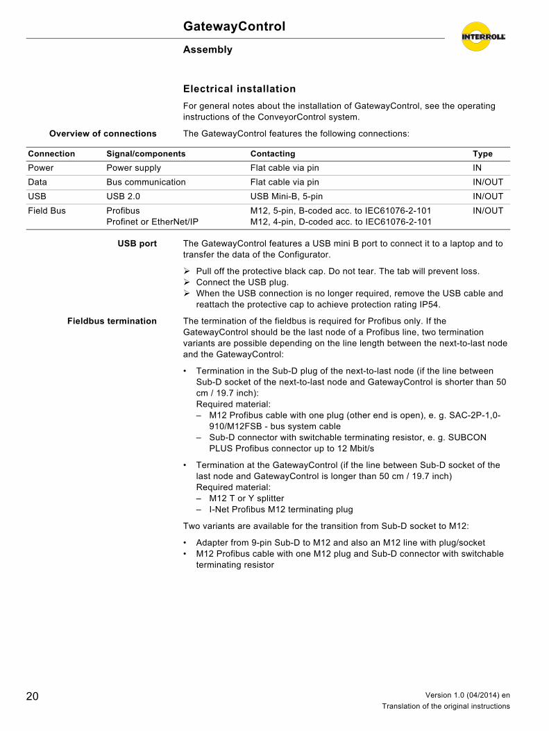
Overview of connections The GatewayControl features the following connections:
USB port The GatewayControl features a USB mini B port to connect it to a laptop and to transfer the data of the Configurator.
Pull off the protective black cap. Do not tear. The tab will prevent loss. Connect the USB plug. When the USB connection is no longer required, remove the USB cable and
reattach the protective cap to achieve protection rating IP54.
Fieldbus termination The termination of the fieldbus is required for Profibus only. If the GatewayControl should be the last node of a Profibus line, two termination variants are possible depending on the line length between the next-to-last node and the GatewayControl:
• Termination in the Sub-D plug of the next-to-last node (if the line between Sub-D socket of the next-to-last node and GatewayControl is shorter than 50 cm / 19.7 inch):Required material:– M12 Profibus cable with one plug (other end is open), e. g. SAC-2P-1,0-
910/M12FSB - bus system cable– Sub-D connector with switchable terminating resistor, e. g. SUBCON
PLUS Profibus connector up to 12 Mbit/s
• Termination at the GatewayControl (if the line between Sub-D socket of the last node and GatewayControl is longer than 50 cm / 19.7 inch)Required material:– M12 T or Y splitter– I-Net Profibus M12 terminating plug
Two variants are available for the transition from Sub-D socket to M12:
• Adapter from 9-pin Sub-D to M12 and also an M12 line with plug/socket• M12 Profibus cable with one M12 plug and Sub-D connector with switchable
terminating resistor
Connection Signal/components Contacting Type
Power Power supply Flat cable via pin IN
Data Bus communication Flat cable via pin IN/OUT
USB USB 2.0 USB Mini-B, 5-pin IN/OUT
Field Bus ProfibusProfinet or EtherNet/IP
M12, 5-pin, B-coded acc. to IEC61076-2-101M12, 4-pin, D-coded acc. to IEC61076-2-101
IN/OUT
20 Version 1.0 (04/2014) en
Translation of the original instructions
GatewayControl
Assembly
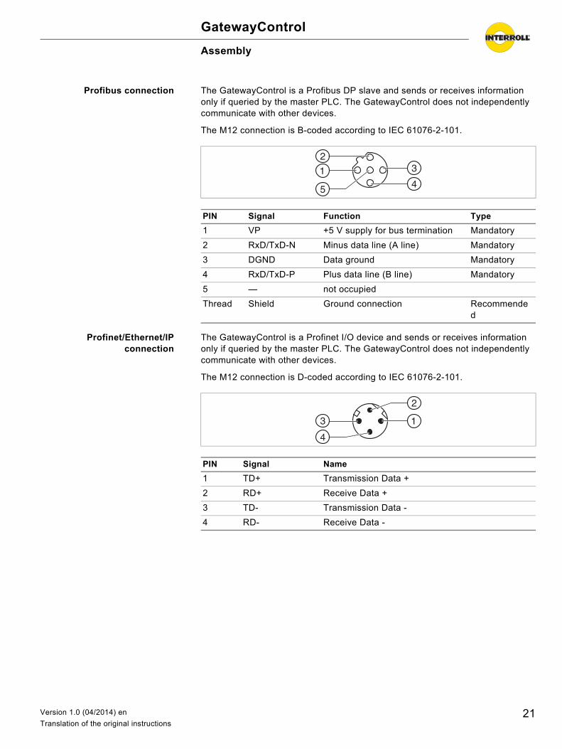
Profibus connection The GatewayControl is a Profibus DP slave and sends or receives information only if queried by the master PLC. The GatewayControl does not independently communicate with other devices.
The M12 connection is B-coded according to IEC 61076-2-101.
Profinet/Ethernet/IPconnection
The GatewayControl is a Profinet I/O device and sends or receives information only if queried by the master PLC. The GatewayControl does not independently communicate with other devices.
The M12 connection is D-coded according to IEC 61076-2-101.
PIN Signal Function Type
1 VP +5 V supply for bus termination Mandatory
2 RxD/TxD-N Minus data line (A line) Mandatory
3 DGND Data ground Mandatory
4 RxD/TxD-P Plus data line (B line) Mandatory
5 — not occupied
Thread Shield Ground connection Recommended
PIN Signal Name
1 TD+ Transmission Data +
2 RD+ Receive Data +
3 TD- Transmission Data -
4 RD- Receive Data -
21Version 1.0 (04/2014) en
Translation of the original instructions
GatewayControl
Assembly
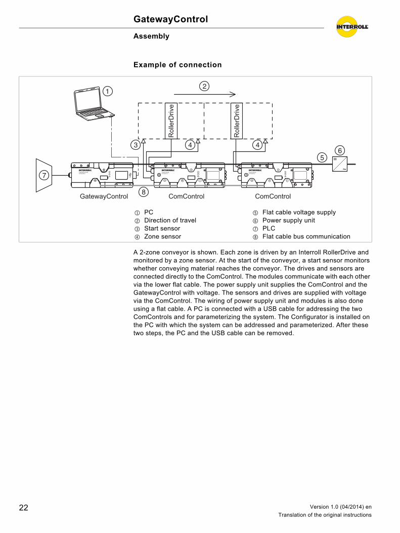
Example of connection
A 2-zone conveyor is shown. Each zone is driven by an Interroll RollerDrive and monitored by a zone sensor. At the start of the conveyor, a start sensor monitors whether conveying material reaches the conveyor. The drives and sensors are connected directly to the ComControl. The modules communicate with each other via the lower flat cable. The power supply unit supplies the ComControl and the GatewayControl with voltage. The sensors and drives are supplied with voltage via the ComControl. The wiring of power supply unit and modules is also done using a flat cable. A PC is connected with a USB cable for addressing the two ComControls and for parameterizing the system. The Configurator is installed on the PC with which the system can be addressed and parameterized. After these two steps, the PC and the USB cable can be removed.
1 PC2 Direction of travel3 Start sensor4 Zone sensor
5 Flat cable voltage supply6 Power supply unit7 PLC8 Flat cable bus communication
GatewayControl ComControl
Rol
lerD
rive
Rol
lerD
rive
ComControl
=
22 Version 1.0 (04/2014) en
Translation of the original instructions
GatewayControl
Initial startup and operation
Initial startup
Checks before initial startup Ensure that all ConveyorControl modules have been correctly fastened to the profile and that all screws have been correctly tightened.
Ensure that there are no additional areas of danger caused by interfaces to other components.
Ensure that the wiring is in accordance with the specification and legal directives.
Check all protection devices. Ensure there are no bystanders in dangerous areas around the conveyor.
Pre-commissioning checks Check all ConveyorControl modules for visible damage. Check all protection devices. Ensure that no RollerDrive is blocked. Clearly specify and monitor the way goods are placed on the conveyor. Ensure there are no bystanders in dangerous areas around the conveyor.
Parameterizing the GatewayControl
Below is a description of only the steps required for parameterizing the GatewayControl. All other details for commissioning and operation of the complete system are located in the operating instructions of the ConveyorControl system.
Using the USB cable, connect the computer with the GatewayControl. Map the ConveyorControl system. In the process, select the type of
GatewayControl (Profibus, Profinet or EtherNet/IP). Prepare the addressing.
Address the ConveyorControl system. Download the parameters. De-energize all ConveyorControl components, insert the fieldbus cable in
connector M12 and secure it with the coupling ring. Switch the supply voltage on again.
After a maximum of 20 seconds, the control connects with the GatewayControl.
Operation
Details about the operation are located in the operating instructions of the ConveyorControl system.
Hint
The GatewayControl is set to node ID 1 at the factory. It cannot be changed in the context of the addressing procedure required for the other modules or assigned to another module.
23Version 1.0 (04/2014) en
Translation of the original instructions

GatewayControl
Maintenance and cleaningDetails about the maintenance and cleaning are located in the operating instructions of the ConveyorControl system.
24 Version 1.0 (04/2014) en
Translation of the original instructions
GatewayControl
Troubleshooting
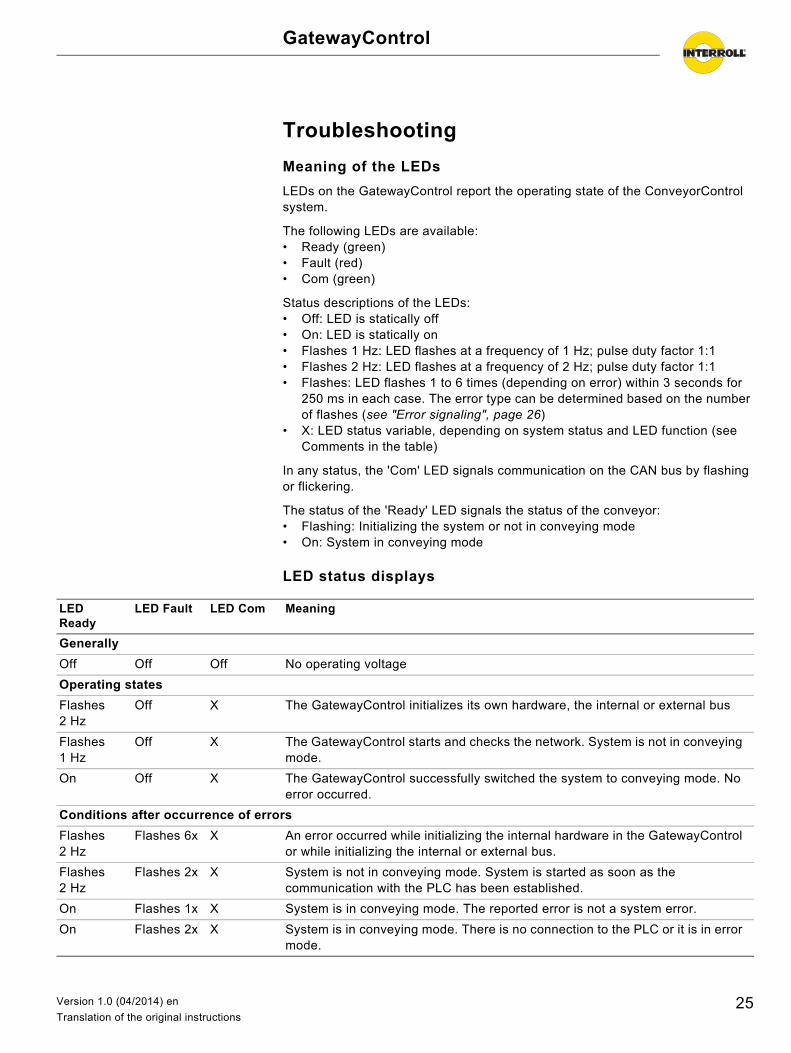
Meaning of the LEDs
LEDs on the GatewayControl report the operating state of the ConveyorControl system.
The following LEDs are available:• Ready (green)• Fault (red)• Com (green)
Status descriptions of the LEDs:• Off: LED is statically off• On: LED is statically on• Flashes 1 Hz: LED flashes at a frequency of 1 Hz; pulse duty factor 1:1• Flashes 2 Hz: LED flashes at a frequency of 2 Hz; pulse duty factor 1:1• Flashes: LED flashes 1 to 6 times (depending on error) within 3 seconds for
250 ms in each case. The error type can be determined based on the number of flashes (see "Error signaling", page 26)
• X: LED status variable, depending on system status and LED function (see Comments in the table)
In any status, the 'Com' LED signals communication on the CAN bus by flashing or flickering.
The status of the 'Ready' LED signals the status of the conveyor:• Flashing: Initializing the system or not in conveying mode• On: System in conveying mode
LED status displays
LED Ready
LED Fault LED Com Meaning
Generally
Off Off Off No operating voltage
Operating states
Flashes 2 Hz
Off X The GatewayControl initializes its own hardware, the internal or external bus
Flashes 1 Hz
Off X The GatewayControl starts and checks the network. System is not in conveying mode.
On Off X The GatewayControl successfully switched the system to conveying mode. No error occurred.
Conditions after occurrence of errors
Flashes 2 Hz
Flashes 6x X An error occurred while initializing the internal hardware in the GatewayControl or while initializing the internal or external bus.
Flashes 2 Hz
Flashes 2x X System is not in conveying mode. System is started as soon as the communication with the PLC has been established.
On Flashes 1x X System is in conveying mode. The reported error is not a system error.
On Flashes 2x X System is in conveying mode. There is no connection to the PLC or it is in error mode.
25Version 1.0 (04/2014) en
Translation of the original instructions
GatewayControl
Troubleshooting
Error signaling
The error type can be determined by the number of flashes of the Fault LED (in a 3-second interval):
Behavior in case of an error
Occurring errors are distinguished in 2 categories: Status errors and system errors.
If errors occurred in the system (status errors or system errors), the control can query the current error status from zones or the GatewayControl itself (zone address = 0) by querying the error register (ERR) via acyclical accesses.
Status error Status errors are non-critical errors of nodes in the ConveyorControl system. They can potentially limit the operation of the system, but they do not cause the system to be switched out of conveying mode. This includes all the errors that are not parameterized or defined as system errors for the respective node, such as logic errors, sensor errors or RollerDrive errors.nbsp
When status errors occur, the error bit in the zone process data (LSCR) of the respective control module is set to signal the presence of an error for this zone. Depending on the control variant (Full PLC control or I/O PLC control), additional error bits are set in the zone process data (LSCR) of the pertinent zone that can already specify the error in more detail. In addition, the error bit is set in the global status register of the system (GSCR). This register should represent the first starting point when checking for errors since it reflects the summary status of errors in the GRC system.
Off Flashes 4x X The GatewayControl detected a critical system error in the voltage level. The system was stopped due to a critical error.
Off Flashes 6x X The system was stopped due to a critical error and is not in conveying mode.
LED Ready
LED Fault LED Com Meaning
Number of flashes
Error Comment
1 Non-critical error within the ConveyorControl system
2 No connection to PLC System cannot be started or is being stopped. After solving the error, the system can be restarted.
4 Voltage error at the GatewayControl
System is stopped due to the voltage error. A voltage reset must be performed (same as system error).
6 The GatewayControl detected a system error
System is stopped due to the system error. A voltage reset must be performed.
26 Version 1.0 (04/2014) en
Translation of the original instructions
GatewayControl
Troubleshooting
An additional notification to the master control does not take place. That is, the control must cyclically analyze the status register of the system (GSCR) to determine existing status errors.
System error System errors are critical errors by nodes in the ConveyorControl system, including the GatewayControl itself. This includes all the errors that are parameterized or defined as system error for the respective node (e.g. voltage errors, temperature errors, communication errors or similar). These errors cause the system to be switched out of conveying mode to ensure system safety. Acyclical services are still possible if the cause was not a failure of communication to the master control.
When system errors occur, the error bit in the zone process data (LSCR) of the respective control module is set to signal the presence of an error for this zone. In addition, the error bit is set in the global status register of the system (GSCR). Since system errors are potentially critical errors that could place the system integrity at risk, the system is switched out of conveying mode and stopped. The exchange of cyclical zone process data is no longer possible on the bus. That means, whenever system errors occur, the cyclical process data (except for error bits) must be evaluated as invalid! Acyclical services are still possible if the cause was not a failure of communication to the master control.
When system errors occur, the GatewayControl transmits a diagnostics alarm to the master control for Profibus or Profinet fieldbus. The diagnostics alarm must have been activated earlier during project planning. An acknowledgment of the alarm by the control is not required. The cause of the occurring error is specified in more detail in the data for the diagnostics alarm. The useful data content of the diagnostics alarm consists of 4 bytes of manufacturer-specific data, identical to the expanded diagnostics, that provide information about the cause of the system error. Once a diagnostics alarm has been reported, it is no longer reset by the GatewayControl since system errors can be reset only by a voltage reset.
27Version 1.0 (04/2014) en
Translation of the original instructions

GatewayControl
Decommissioning and disposalDetails about the decommissioning and disposal are located in the operating instructions of the ConveyorControl system.
28 Version 1.0 (04/2014) en
Translation of the original instructions
GatewayControl
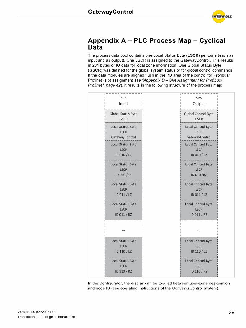
Appendix A – PLC Process Map – Cyclical DataThe process data pool contains one Local Status Byte (LSCR) per zone (each as input and as output). One LSCR is assigned to the GatewayControl. This results in 201 bytes of IO data for local zone information. One Global Status Byte (GSCR) was defined for the global system status or for global control commands. If the data modules are aligned flush in the I/O area of the control for Profibus/Profinet (slot assignment see "Appendix D – Slot Assignment for Profibus/Profinet", page 42), it results in the following structure of the process map:
In the Configurator, the display can be toggled between user-zone designation and node ID (see operating instructions of the ConveyorControl system).
Global Status Byte GSCR
SPS -
Local Status Byte LSCR
ID 010 / LZ
…
Local Status Byte LSCR
GatewayControl
SPS Input
Local Status Byte LSCR
ID 010 /RZ
Local Status Byte LSCR
ID 011 / LZ
Local Status Byte LSCR
ID 011 / RZ
Local Status Byte LSCR
ID 110 / LZ
Local Status Byte LSCR
ID 110 / RZ
Global Control Byte GSCR
SPS-
Local Control Byte LSCR
ID 010 / LZ
…
Local Control Byte LSCR
GatewayControl
SPSOutput
Local Control Byte LSCR
ID 010 /RZ
Local Control Byte LSCR
ID 011 / LZ
Local Control Byte LSCR
ID 011 / RZ
Local Control Byte LSCR
ID 110 / LZ
Local Control Byte LSCR
ID 110 / RZ
29Version 1.0 (04/2014) en
Translation of the original instructions
GatewayControl
Appendix A – PLC Process Map – Cyclical Data
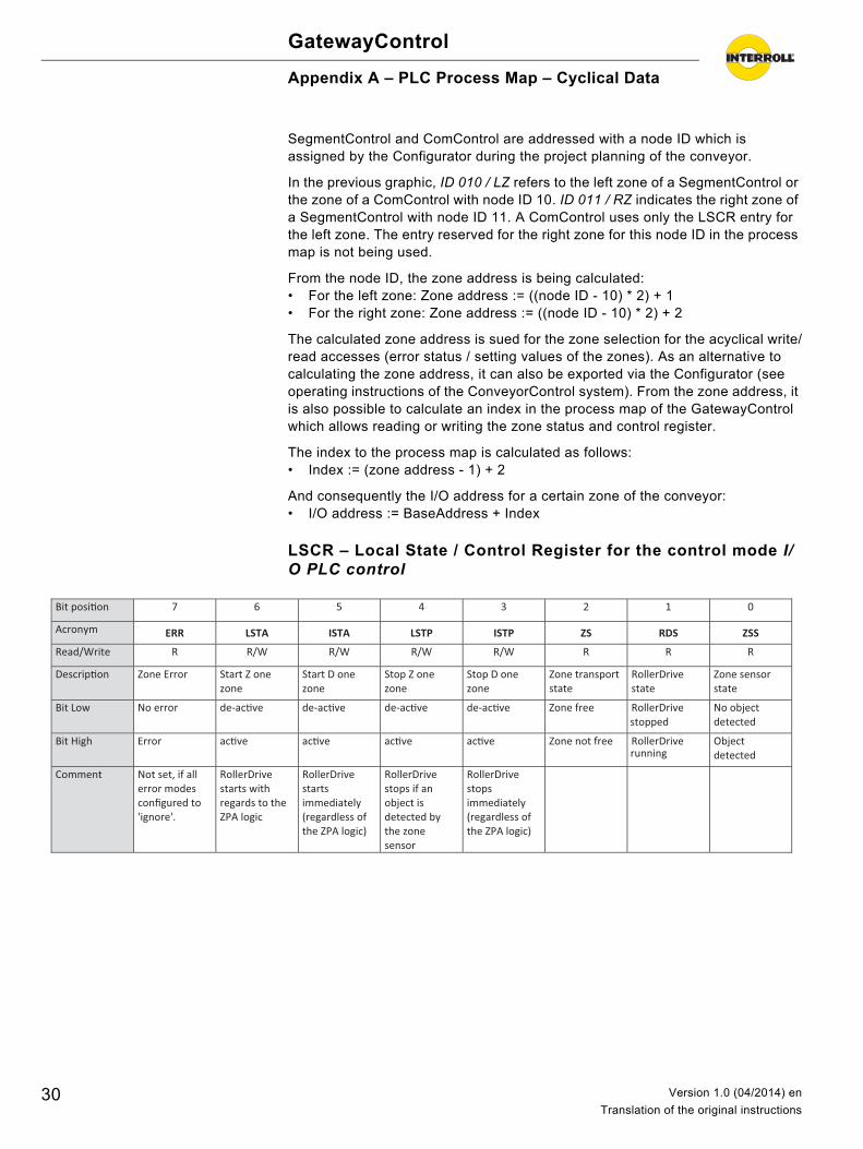
SegmentControl and ComControl are addressed with a node ID which is assigned by the Configurator during the project planning of the conveyor.
In the previous graphic, ID 010 / LZ refers to the left zone of a SegmentControl or the zone of a ComControl with node ID 10. ID 011 / RZ indicates the right zone of a SegmentControl with node ID 11. A ComControl uses only the LSCR entry for the left zone. The entry reserved for the right zone for this node ID in the process map is not being used.
From the node ID, the zone address is being calculated:• For the left zone: Zone address := ((node ID - 10) * 2) + 1• For the right zone: Zone address := ((node ID - 10) * 2) + 2
The calculated zone address is sued for the zone selection for the acyclical write/read accesses (error status / setting values of the zones). As an alternative to calculating the zone address, it can also be exported via the Configurator (see operating instructions of the ConveyorControl system). From the zone address, it is also possible to calculate an index in the process map of the GatewayControl which allows reading or writing the zone status and control register.
The index to the process map is calculated as follows:• Index := (zone address - 1) + 2
And consequently the I/O address for a certain zone of the conveyor:• I/O address := BaseAddress + Index
LSCR – Local State / Control Register for the control mode I/O PLC control
Bit posi�on 7 6 5 4 3 2 1 0
Acronym ERR LSTA ISTA LSTP ISTP ZS RDS ZSS
Read/Write R R/W R/W R/W R/W R R R
Descrip�on Zone Error Start Z one zone
Start D one zone
Stop Z one zone
Stop D one zone
Zone transport state
RollerDrive state
Zone sensor state
Bit Low No error de-ac�ve de-ac�ve de-ac�ve de-ac�ve Zone free RollerDrive stopped
No object detected
Bit High Error ac�ve ac�ve ac�ve ac�ve Zone not free RollerDrive running
Object detected
Comment Not set, if all error modes configured to 'ignore'.
RollerDrive starts with regards to the ZPA logic
RollerDrive starts immediately (regardless of the ZPA logic)
RollerDrive stops if an object is detected by the zone sensor
RollerDrive stops immediately (regardless of the ZPA logic)
30 Version 1.0 (04/2014) en
Translation of the original instructions
GatewayControl
Appendix A – PLC Process Map – Cyclical Data
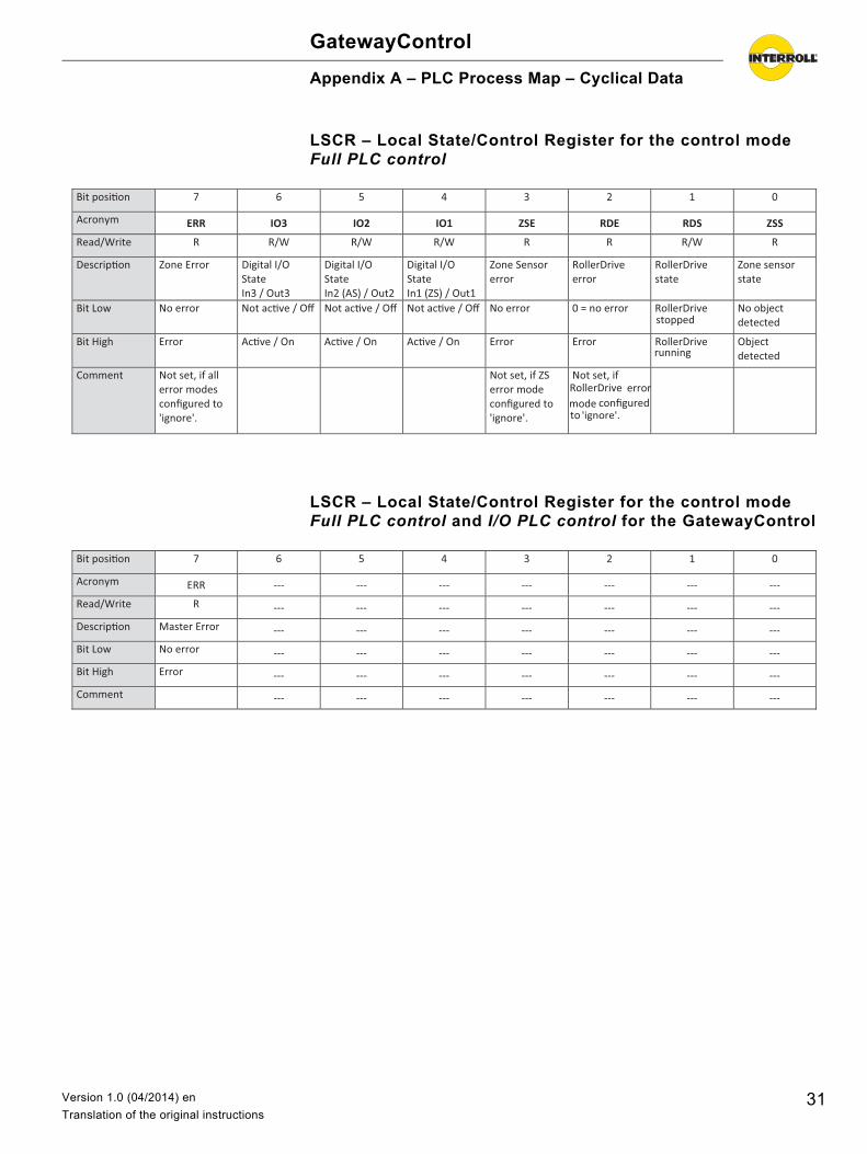
LSCR – Local State/Control Register for the control mode Full PLC control
LSCR – Local State/Control Register for the control mode Full PLC control and I/O PLC control for the GatewayControl
Bit posi�on 7 6 5 4 3 2 1 0
Acronym ERR IO3 IO2 IO1 ZSE RDE RDS ZSS
Read/Write R R/W R/W R/W R R R/W R
Descrip�on Zone Error Digital I/O State In3 / Out3
Digital I/O State In2 (AS) / Out2
Digital I/O State In1 (ZS) / Out1
Zone Sensor error
RollerDrive error
RollerDrive state
Zone sensor state
Bit Low No error Not ac�ve / Off Not ac�ve / Off Not ac�ve / Off No error 0 = no error RollerDrive stopped
No object detected
Bit High Error Ac�ve / On Ac�ve / On Ac�ve / On Error Error RollerDrive running
Object detected
Comment Not set, if all error modes configured to 'ignore'.
Not set, if ZS error mode configured to 'ignore'.
Not set, if RollerDrive
error
mode
configured to
'ignore'.
Bit posi�on 7 6 5 4 3 2 1 0
Acronym ERR --- --- --- --- --- --- ---
Read/Write R --- --- --- --- --- --- ---
Descrip�on Master Error --- --- --- --- --- --- ---
Bit Low No error --- --- --- --- --- --- ---
Bit High Error --- --- --- --- --- --- ---
Comment --- --- --- --- --- --- ---
31Version 1.0 (04/2014) en
Translation of the original instructions
GatewayControl
Appendix A – PLC Process Map – Cyclical Data
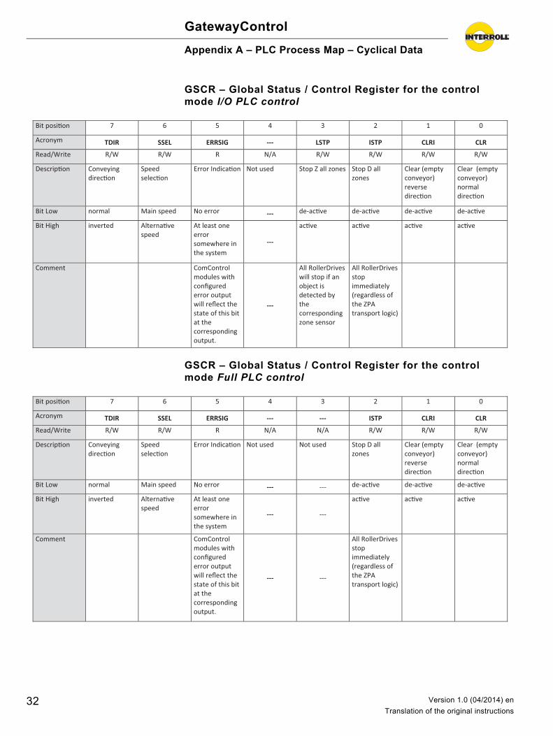
GSCR – Global Status / Control Register for the control mode I/O PLC control
GSCR – Global Status / Control Register for the control mode Full PLC control
Bit posi�on 7 6 5 4 3 2 1 0
Acronym TDIR SSEL ERRSIG --- LSTP ISTP CLRI CLR
Read/Write R/W R/W R N/A R/W R/W R/W R/W
Descrip�on Conveying direc�on
Speed selec�on
Error Indica�on Not used Stop Z all zones Stop D all zones
Clear (empty conveyor) reverse direc�on
Clear (empty conveyor) normal direc�on
Bit Low normal Main speed No error --- de-ac�ve de-ac�ve de-ac�ve de-ac�ve
Bit High inverted Alterna�ve speed
At least one error somewhere in the system
---
ac�ve ac�ve ac�ve ac�ve
Comment ComControl modules with configured error output will reflect the state of this bit at the corresponding output.
---
All RollerDrives will stop if an object is detected by the corresponding zone sensor
All RollerDrives stop immediately (regardless of the ZPA transport logic)
Bit posi�on 7 6 5 4 3 2 1 0
Acronym TDIR SSEL ERRSIG --- --- ISTP CLRI CLR
Read/Write R/W R/W R N/A N/A R/W R/W R/W
Descrip�on Conveying direc�on
Speed selec�on
Error Indica�on Not used Not used Stop D all zones
Clear (empty conveyor) reverse direc�on
Clear (empty conveyor) normal direc�on
Bit Low normal Main speed No error --- --- de-ac�ve de-ac�ve de-ac�ve
Bit High inverted Alterna�ve speed
At least one error somewhere in the system
--- ---
ac�ve ac�ve ac�ve
Comment ComControl modules with configured error output will reflect the state of this bit at the corresponding output.
--- ---
All RollerDrives stop immediately (regardless of the ZPA transport logic)
32 Version 1.0 (04/2014) en
Translation of the original instructions
GatewayControl
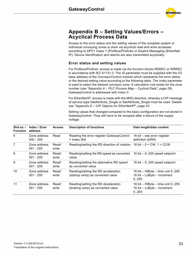
Appendix B – Setting Values/Errors – Acyclical Process DataAccess to the error status and the setting values of the complete system or individual conveying zones is done via acyclical read and write accesses according to DPV1 Class 1 (Profibus/Profinet) or Explicit Messaging (EtherNet/IP). Device identification and alarms are also transmitted acyclically.
Error status and setting values
For Profibus/Profinet, access is made via the function blocks RDREC or WRREC in accordance with IEC 61131-3. The ID parameter must be supplied with the I/O base address of the ConveyorControl module which represents the error status or the desired setting value according to the following table. The Index parameter is used to select the desired conveyor zone. A calculation rule exists for the zone number (see "Appendix A – PLC Process Map – Cyclical Data", page 29). GatewayControl is addressed with index 0.
For EtherNet/IP, access is made with the MSG directive, whereby a CIP message of service type GetAttribute_Single or SetAttribute_Single must be used. Details see "Appendix E – CIP Objects for EtherNet/IP", page 43.
Setting values that changed compared to the basic configuration are not stored in GatewayControl. They will have to be recopied after a failure of the supply voltage.
Slot no. / Function
Index / Zone address
Access Description of functions Data length/data content
6 Zone address000 - 200
Read Reading the error register GatewayControl = Index 000
16 bit – see error register definition (ERR)
7 Zone address001 - 200
Read/write
Reading/setting the RD direction of rotation 16 bit – 0 = CW, 1 = CCW
8 Zone address001 - 200
Read/write
Reading/setting the RD speed as converted value
16 bit – 0..255 speed setpoint
9 Zone address001 - 200
Read/write
Reading/setting the alternative RD speed as converted value
16 bit – 0..255 speed setpoint
10 Zone address001 - 200
Read/write
Reading/setting the RD acceleration (startup ramp) as converted value
16 bit – HiByte – time unit 0..25516 bit – LoByte – increment 0..255
11 Zone address001 - 200
Read/write
Reading/setting the RD deceleration (braking ramp) as converted value
16 bit – HiByte – time unit 0..25516 bit – LoByte – increment 0..255
33Version 1.0 (04/2014) en
Translation of the original instructions
GatewayControl
Appendix B – Setting Values/Errors – Acyclical Process Data
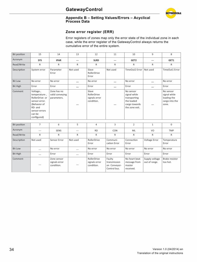
Zone error register (ERR)
Error registers of zones map only the error state of the individual zone in each case, while the error register of the GatewayControl always returns the cumulative error of the entire system.
Bit posi�on 15 14 13 12 11 10 9 8
Acronym SYS IPAR --- SLRD --- GET2 --- GET1
Read/Write R R R R R R R R
Descrip�on System error Parameter Error
Not used Slave RollerDrive Error
Not used TimeOut2 Error Not used TimeOut1 Error
Bit Low No error No error --- No error --- No error --- No error
Bit High Error Error --- Error --- Error --- Error
Comment Voltage-, temperature-, RollerDrive- or sensor-error. (Behavior of RD- and sensor-errors can be configured)
Zone has no valid conveying parameters.
---
Slave RollerDrive signals error condi�on.
---
No sensor signal while transpor�ng the loaded cargo towards the zone exit.
---
No sensor signal while loading the cargo into the zone.
Bit posi�on 7 6 5 4 3 2 1 0
Acronym --- SENS --- RD CON ML VO TMP
Read/Write R R R R R R R R
Descrip�on Not used Sensor Error Not used RollerDrive Error
Communi-ca�on Error
Connec�on Error
Voltage Error Temperature Error
Bit Low --- No error --- No error No error No error No error No error
Bit High --- Error --- Error Error Error Error Error
Comment
---
Zone sensor signals error condi�on. ---
RollerDrive signals error condi�on.
Faulty transmission on Conveyor-Control bus.
No heart beat message from master received.
Supply voltage out of range.
Brake resistor too hot.
34 Version 1.0 (04/2014) en
Translation of the original instructions
GatewayControl
Appendix B – Setting Values/Errors – Acyclical Process Data
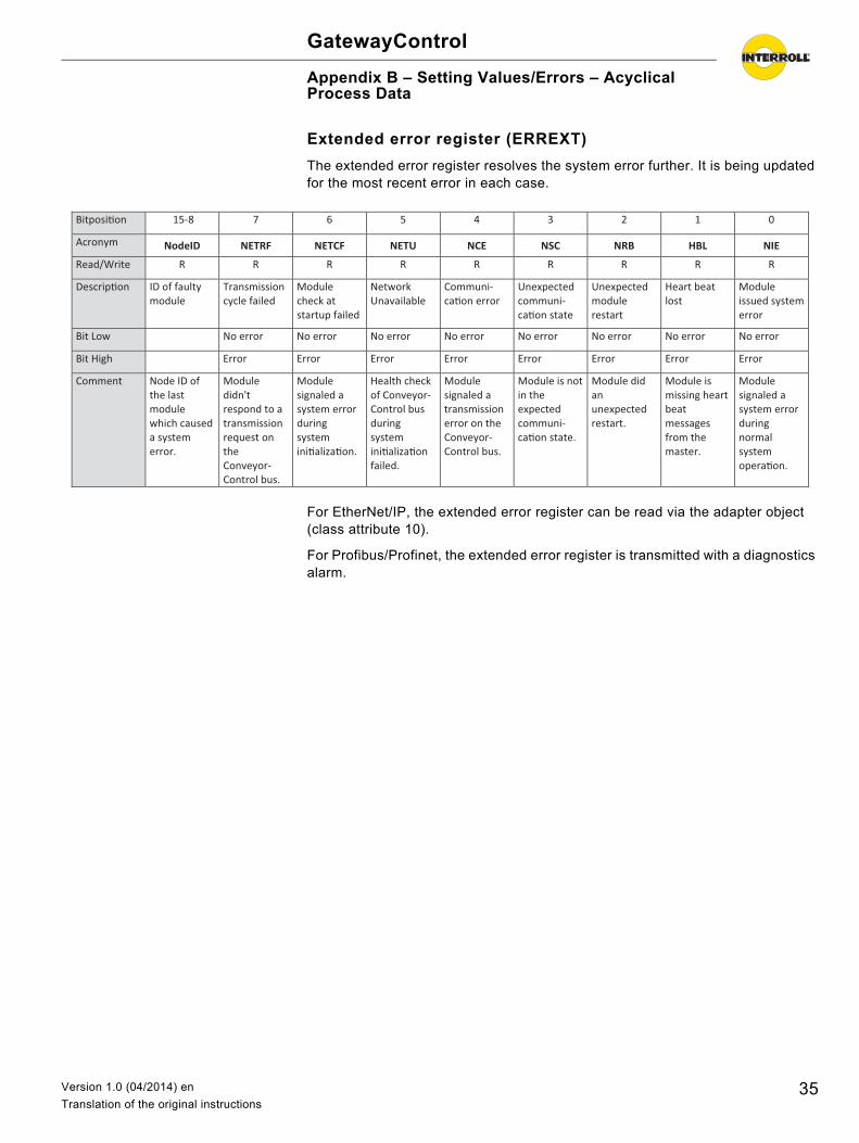
Extended error register (ERREXT)
The extended error register resolves the system error further. It is being updated for the most recent error in each case.
For EtherNet/IP, the extended error register can be read via the adapter object (class attribute 10).
For Profibus/Profinet, the extended error register is transmitted with a diagnostics alarm.
Bitposi�on 15-8 7 6 5 4 3 2 1 0
Acronym NodeID NETRF NETCF NETU NCE NSC NRB HBL NIE
Read/Write R R R R R R R R R
Descrip�on ID of faulty module
Transmission cycle failed
Module check at startup failed
Network Unavailable
Communi-ca�on error
Unexpected communi-ca�on state
Unexpected module restart
Heart beat lost
Module issued system error
Bit Low No error No error No error No error No error No error No error No error
Bit High Error Error Error Error Error Error Error Error
Comment Node ID of the last module which caused a system error.
Module didn't respond to a transmission request on the Conveyor-Control bus.
Module signaled a system error during system ini�aliza�on.
Health check of Conveyor-Control bus during system ini�aliza�on failed.
Module signaled a transmission error on the Conveyor-Control bus.
Module is not in the expected communi-ca�on state.
Module did an unexpected restart.
Module is missing heart beat messages from the master.
Module signaled a system error during normal system opera�on.
35Version 1.0 (04/2014) en
Translation of the original instructions
GatewayControl
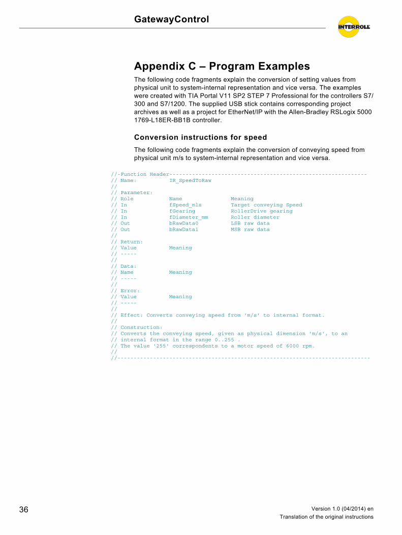
Appendix C – Program ExamplesThe following code fragments explain the conversion of setting values from physical unit to system-internal representation and vice versa. The examples were created with TIA Portal V11 SP2 STEP 7 Professional for the controllers S7/300 and S7/1200. The supplied USB stick contains corresponding project archives as well as a project for EtherNet/IP with the Allen-Bradley RSLogix 5000 1769-L18ER-BB1B controller.
Conversion instructions for speed
The following code fragments explain the conversion of conveying speed from physical unit m/s to system-internal representation and vice versa.
//-Function Header------------------------------------------------------------- // Name: IR_SpeedToRaw // // Parameter: // Role Name Meaning // In fSpeed_mls Target conveying Speed // In fGearing RollerDrive gearing // In fDiameter_mm Roller diameter // Out bRawData0 LSB raw data // Out bRawData1 MSB raw data // // Return: // Value Meaning // ----- // // Data: // Name Meaning // ----- // // Error: // Value Meaning // ----- // // Effect: Converts conveying speed from 'm/s' to internal format. // // Construction: // Converts the conveying speed, given as physical dimension 'm/s', to an // internal format in the range 0..255 . // The value '255' correspondents to a motor speed of 6000 rpm. // //------------------------------------------------------------------------------
36 Version 1.0 (04/2014) en
Translation of the original instructions
GatewayControl
Appendix C – Program Examples
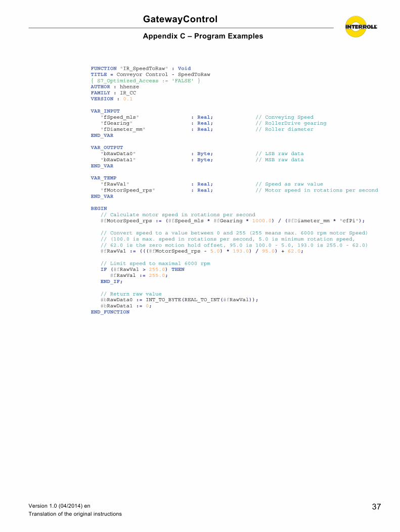
FUNCTION "IR_SpeedToRaw" : Void TITLE = Conveyor Control - SpeedToRaw { S7_Optimized_Access := 'FALSE' }AUTHOR : hhenze FAMILY : IR_CC VERSION : 0.1
VAR_INPUT "fSpeed_mls" : Real; // Conveying Speed "fGearing" : Real; // RollerDrive gearing "fDiameter_mm" : Real; // Roller diameter END_VAR
VAR_OUTPUT "bRawData0" : Byte; // LSB raw data "bRawData1" : Byte; // MSB raw data END_VAR
VAR_TEMP "fRawVal" : Real; // Speed as raw value "fMotorSpeed_rps" : Real; // Motor speed in rotations per second END_VAR
BEGIN // Calculate motor speed in rotations per second #fMotorSpeed_rps := (#fSpeed_mls * #fGearing * 1000.0) / (#fDiameter_mm * "cfPi");
// Convert speed to a value between 0 and 255 (255 means max. 6000 rpm motor Speed) // (100.0 is max. speed in rotations per second, 5.0 is minimum rotation speed, // 62.0 is the zero motion hold offset, 95.0 is 100.0 - 5.0, 193.0 is 255.0 - 62.0) #fRawVal := (((#fMotorSpeed_rps - 5.0) * 193.0) / 95.0) + 62.0;
// Limit speed to maximal 6000 rpm IF (#fRawVal > 255.0) THEN #fRawVal := 255.0; END_IF;
// Return raw value #bRawData0 := INT_TO_BYTE(REAL_TO_INT(#fRawVal)); #bRawData1 := 0; END_FUNCTION
37Version 1.0 (04/2014) en
Translation of the original instructions
GatewayControl
Appendix C – Program Examples
//-Function Header------------------------------------------------------------- // Name: IR_RawToSpeed // // Parameter: // Role Name Meaning // In aRawData Speed as raw value // In fGearing RollerDrive gearing // In fDiameter_mm Roller diameter // // Return: // Value Meaning // >=0.0 Conveying speed in m/s // // Data: // Name Meaning // ----- // // Error: // Value Meaning // ----- // // Effect: Converts conveying speed from internal format to 'm/s'. // // Construction: // Converts the conveying speed, given as internal format in the range 0..255, // to the physical dimension 'm/s' . // The value '255' correspondents to a motor speed of 6000 rpm. // //------------------------------------------------------------------------------
FUNCTION "IR_RawToSpeed" : Real TITLE = Conveyor Control - RawToSpeed { S7_Optimized_Access := 'FALSE' }AUTHOR : hhenze FAMILY : IR_CC VERSION : 0.1
VAR_INPUT "aRawData" : Array [0..1] of Byte; // Speed as raw value "fGearing" : Real; // RollerDrive gearing "fDiameter_mm" : Real; // Roller diameter END_VAR
VAR_TEMP "fRawVal" : Real; // Raw value as float "fMotorSpeed_rps" : Real; // Motor speed in rotations per second END_VAR
BEGIN // Convert raw value to float #fRawVal := INT_TO_REAL(BYTE_TO_INT(#aRawData[0]));
// Calculate motor speed in rotations per second (255 means max. 6000 rpm motor Speed) // (100.0 is max. speed in rotations per second, 5.0 is minimum rotation speed, // 62.0 is the zero motion hold offset, 95.0 is 100.0 - 5.0, 193.0 is 255.0 - 62.0) #fMotorSpeed_rps := (((#fRawVal - 62.0) * 95.0) / 193.0) + 5.0;
// Convert raw speed to conveying speed in 'm/s' ('255' raw value means 6000 rpm motor) #IR_RawToSpeed := (#fMotorSpeed_rps * #fDiameter_mm * "cfPi") / (#fGearing * 1000.0); END_FUNCTION
38 Version 1.0 (04/2014) en
Translation of the original instructions
GatewayControl
Appendix C – Program Examples
Conversion instructions for acceleration
The following code fragments explain the conversion of the acceleration (deceleration= analogous) from physical unit m/s2 to system-internal representation and vice versa.
//-Function Header------------------------------------------------------------- // Name: IR_AccelToRaw // // Parameter: // Role Name Meaning // In fAccel_mls2 Target acceleration // In fGearing RollerDrive gearing // In fDiameter_mm Roller diameter // Out bRawData0 LSB raw data // Out bRawData1 MSB raw data // // Return: // Value Meaning // ----- // // Data: // Name Meaning // ----- // // Error: // Value Meaning // ----- // // Effect: Converts acceleration from 'm/s2' to internal format. // // Construction: // Converts the acceleration, given as physical dimension 'm/s2', to// an internal format. This is a value pair, comprising speed increment // per acceleration intervall and the acceleration intervall time. // Maximum possible motor speed is 6000 rpm and correspondents to a // speed value of '255'. // //------------------------------------------------------------------------------
39Version 1.0 (04/2014) en
Translation of the original instructions
GatewayControl
Appendix C – Program Examples
FUNCTION "IR_AccelToRaw" : Void TITLE = Conveyor Control - IR_AccelToRaw { S7_Optimized_Access := 'FALSE' }AUTHOR : hhenze FAMILY : IR_CC VERSION : 0.2
VAR_INPUT "fAccel_mls2" : Real; // Acceleration "fGearing" : Real; // RollerDrive gearing "fDiameter_mm" : Real; // Roller diameter END_VAR
VAR_OUTPUT "bRawData0" : Byte; // LSB raw data "bRawData1" : Byte; // MSB raw data END_VAR
VAR_TEMP "fMaxSpeed_mls" : Real; // Maximum possible speed "fDeltaSpeed_mls" : Real; // Speed increment per accel. intervall "fAccelTime_ms" : Real; // Acceleration time "fIntervallTime_ms" : Real; // Acceleration intervall time "iRawIncrement" : Int; // Raw increment per intervall "iRawIntervall" : Int; // Raw intervall [10 ms] END_VAR
BEGIN // Check, if maximum acceleration requested (0.0) IF (#fAccel_mls2 = 0.0) THEN // Set speed increment and time intervall to 'maximum acceleration' #iRawIncrement := 0; #iRawIntervall := 128; ELSE // Normal processing: // Calculate the maximum possible speed #fMaxSpeed_mls := (#fDiameter_mm * "cfPi" * 0.1) / #fGearing;
// Calculate the acceleration time #fAccelTime_ms := (#fMaxSpeed_mls * 1000.0) / #fAccel_mls2;
// Calculate the acceleration intervall time (20 steps to max. speed) #fIntervallTime_ms := #fAccelTime_ms / 20.0; #fIntervallTime_ms := DINT_TO_REAL(ROUND(#fIntervallTime_ms / 10.0)) * 10.0; IF (#fIntervallTime_ms < 10.0) THEN #fIntervallTime_ms := 10.0; END_IF;
// Calculate raw speed increment and raw time intervall #iRawIncrement := REAL_TO_INT((193.0 * #fIntervallTime_ms * 8.0
) / #fAccelTime_ms); IF (#iRawIncrement > 255) THEN #iRawIncrement := 255; END_IF; #iRawIntervall := REAL_TO_INT(#fIntervallTime_ms / 10.0); IF (#iRawIntervall > 255) THEN #iRawIntervall := 255; END_IF; END_IF;
// Return raw value #bRawData0 := INT_TO_BYTE(#iRawIntervall); #bRawData1 := INT_TO_BYTE(#iRawIncrement); END_FUNCTION
40 Version 1.0 (04/2014) en
Translation of the original instructions
GatewayControl
Appendix C – Program Examples
//-Function Header------------------------------------------------------------- // Name: IR_RawToAccel // // Parameter: // Role Name Meaning // In aRawData Acceleration in internal format// In fGearing RollerDrive gearing // In fDiameter_mm Roller diameter // // Return: // Value Meaning // >=0.0 Acceleration in m/s^2 // // Data: // Name Meaning // ----- // // Error: // Value Meaning // ----- // // Effect: Converts acceleration from internal format to 'm/s2'. // // Construction: // Converts the acceleration, given in an internal format (the speed increment per // acceleration interval and the acceleration intervall time), to the physical // dimension 'm/s2'. // Maximum possible motor speed is 6000 rpm and correspondents to a // speed value of '255'. //------------------------------------------------------------------------------
FUNCTION "IR_RawToAccel" : Real TITLE = Conveyor Control - IR_RawToAccel { S7_Optimized_Access := 'FALSE' }AUTHOR : hhenze FAMILY : IR_CC VERSION : 0.2
VAR_INPUT "aRawData" : Array[0..1] of Byte; // Acceleration in internal format "fGearing" : Real; // RollerDrive gearing "fDiameter_mm" : Real; // Roller diameter END_VAR
VAR_TEMP "fMaxSpeed_mls" : Real; // Maximum possible speed "fIntervalllTime_ms" : Real; // Acceleration intervall time "fMaxSpeed_mls" : Real; // Maximum possible speed "fIntervallTime_ms" : Real; // Acceleration intervall time "fAccelTime_ms" : Real; // Acceleration time "iIncrement" : Int; // Raw increment value "iIntervall" : Int; // Raw intervall value END_VAR
BEGIN // The raw value is split into a speed increment and an acceleration intervall time. #iIntervall := BYTE_TO_INT(#aRawData[0]); #iIncrement := BYTE_TO_INT(#aRawData[1]); // Check, if 'maximum possible acceleration' configured IF (#iIncrement = 0) THEN // Return an acceleration value of '0.0' #IR_RawToAccel := 0.0; ELSE // Normal processing: // Calculate the maximum possible speed #fMaxSpeed_mls := (#fDiameter_mm * "cfPi" * 0.1) / #fGearing;
// Calculate acceleration time #fIntervallTime_ms := INT_TO_REAL(#iIntervall) * 10.0; #fAccelTime_ms := (193.0 * #fIntervallTime_ms * 8.0) / INT_TO_REAL(#iIncrement);
// Calculate the acceleration in m/s2 #IR_RawToAccel := (#fMaxSpeed_mls * 1000.0) / #fAccelTime_ms; END_IF; END_FUNCTION
41Version 1.0 (04/2014) en
Translation of the original instructions
GatewayControl
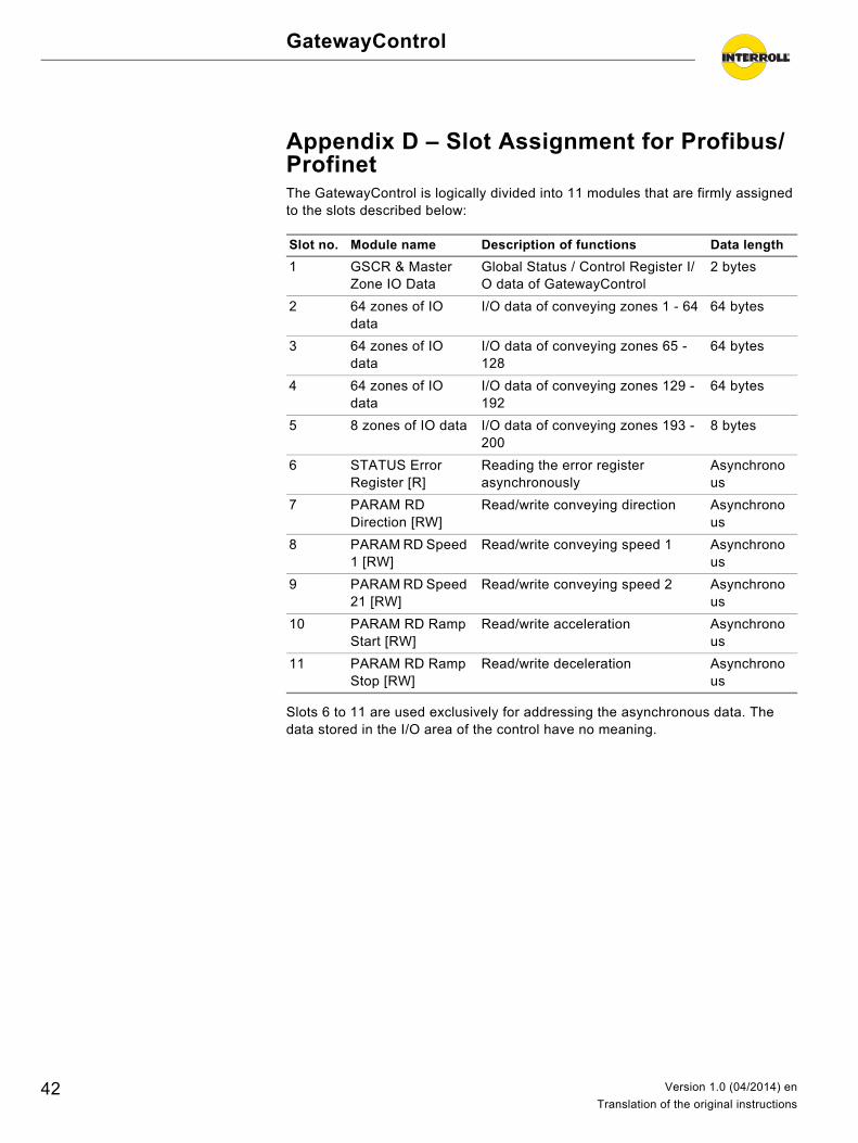
Appendix D – Slot Assignment for Profibus/ProfinetThe GatewayControl is logically divided into 11 modules that are firmly assigned to the slots described below:
Slots 6 to 11 are used exclusively for addressing the asynchronous data. The data stored in the I/O area of the control have no meaning.
Slot no. Module name Description of functions Data length
1 GSCR & Master Zone IO Data
Global Status / Control Register I/O data of GatewayControl
2 bytes
2 64 zones of IO data
I/O data of conveying zones 1 - 64 64 bytes
3 64 zones of IO data
I/O data of conveying zones 65 - 128
64 bytes
4 64 zones of IO data
I/O data of conveying zones 129 - 192
64 bytes
5 8 zones of IO data I/O data of conveying zones 193 - 200
8 bytes
6 STATUS Error Register [R]
Reading the error register asynchronously
Asynchronous
7 PARAM RD Direction [RW]
Read/write conveying direction Asynchronous
8 PARAM RD Speed 1 [RW]
Read/write conveying speed 1 Asynchronous
9 PARAM RD Speed 21 [RW]
Read/write conveying speed 2 Asynchronous
10 PARAM RD Ramp Start [RW]
Read/write acceleration Asynchronous
11 PARAM RD Ramp Stop [RW]
Read/write deceleration Asynchronous
42 Version 1.0 (04/2014) en
Translation of the original instructions
GatewayControl
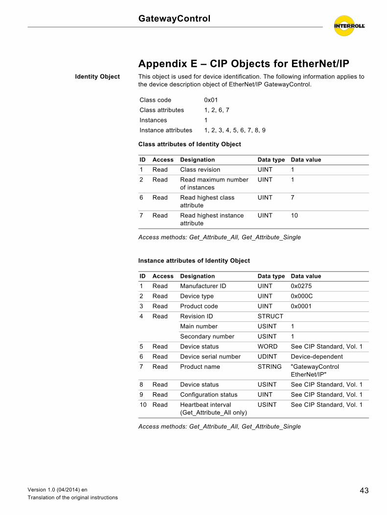
Appendix E – CIP Objects for EtherNet/IPIdentity Object This object is used for device identification. The following information applies to
the device description object of EtherNet/IP GatewayControl.
Class attributes of Identity Object
Access methods: Get_Attribute_All, Get_Attribute_Single
Instance attributes of Identity Object
Access methods: Get_Attribute_All, Get_Attribute_Single
Class code 0x01
Class attributes 1, 2, 6, 7
Instances 1
Instance attributes 1, 2, 3, 4, 5, 6, 7, 8, 9
ID Access Designation Data type Data value
1 Read Class revision UINT 1
2 Read Read maximum number of instances
UINT 1
6 Read Read highest class attribute
UINT 7
7 Read Read highest instance attribute
UINT 10
ID Access Designation Data type Data value
1 Read Manufacturer ID UINT 0x0275
2 Read Device type UINT 0x000C
3 Read Product code UINT 0x0001
4 Read Revision ID STRUCT
Main number USINT 1
Secondary number USINT 1
5 Read Device status WORD See CIP Standard, Vol. 1
6 Read Device serial number UDINT Device-dependent
7 Read Product name STRING "GatewayControl EtherNet/IP"
8 Read Device status USINT See CIP Standard, Vol. 1
9 Read Configuration status UINT See CIP Standard, Vol. 1
10 Read Heartbeat interval (Get_Attribute_All only)
USINT See CIP Standard, Vol. 1
43Version 1.0 (04/2014) en
Translation of the original instructions
GatewayControl
Appendix E – CIP Objects for EtherNet/IP
Assembly object This object allows exchanging cyclical useful data. The following information applies to the device description object of EtherNet/IP GatewayControl.
Class attributes of assembly object
Access methods: Get_Attribute_Single
Instance attributes of assembly object
Access methods: Get_Attribute_Single, Set_Attribute_Single
Connection manager object This object indicates the connection options to the adapter and configures them. The following information applies to the connection manager object of EtherNet/IP GatewayControl.
Class attributes of connection manager object
Access methods: Get_Attribute_Single
Class code 0x04
Class attributes 1, 2
Instances 1
Instance attributes 3, 4
ID Access Designation Data type Data value
1 Read Class revision UINT 1
2 Read Maximum number of instances
UINT X
ID Access Designation Data type Data value
3 Read/set
Data BYTE[] see "Appendix A – PLC Process Map – Cyclical Data", page 29
4 Read Data length UINT 202
Class code 0x06
Class attributes 1, 2
Instances 0
Instance attributes
ID Access Designation Data type Data value
1 Read Class revision UINT 1
2 Read Maximum number of instances
UINT 1
44 Version 1.0 (04/2014) en
Translation of the original instructions
GatewayControl
Appendix E – CIP Objects for EtherNet/IP
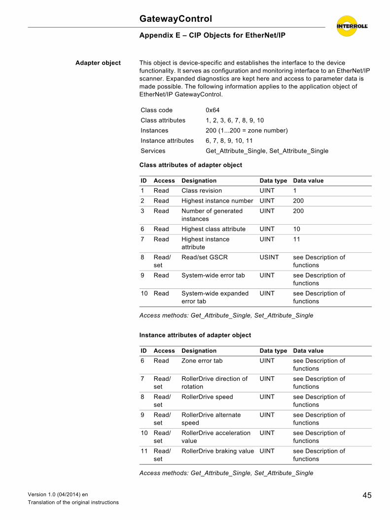
Adapter object This object is device-specific and establishes the interface to the device functionality. It serves as configuration and monitoring interface to an EtherNet/IP scanner. Expanded diagnostics are kept here and access to parameter data is made possible. The following information applies to the application object of EtherNet/IP GatewayControl.
Class attributes of adapter object
Access methods: Get_Attribute_Single, Set_Attribute_Single
Instance attributes of adapter object
Access methods: Get_Attribute_Single, Set_Attribute_Single
Class code 0x64
Class attributes 1, 2, 3, 6, 7, 8, 9, 10
Instances 200 (1...200 = zone number)
Instance attributes 6, 7, 8, 9, 10, 11
Services Get_Attribute_Single, Set_Attribute_Single
ID Access Designation Data type Data value
1 Read Class revision UINT 1
2 Read Highest instance number UINT 200
3 Read Number of generated instances
UINT 200
6 Read Highest class attribute UINT 10
7 Read Highest instance attribute
UINT 11
8 Read/set
Read/set GSCR USINT see Description of functions
9 Read System-wide error tab UINT see Description of functions
10 Read System-wide expanded error tab
UINT see Description of functions
ID Access Designation Data type Data value
6 Read Zone error tab UINT see Description of functions
7 Read/set
RollerDrive direction of rotation
UINT see Description of functions
8 Read/set
RollerDrive speed UINT see Description of functions
9 Read/set
RollerDrive alternate speed
UINT see Description of functions
10 Read/set
RollerDrive acceleration value
UINT see Description of functions
11 Read/set
RollerDrive braking value UINT see Description of functions
45Version 1.0 (04/2014) en
Translation of the original instructions
GatewayControl
Appendix E – CIP Objects for EtherNet/IP
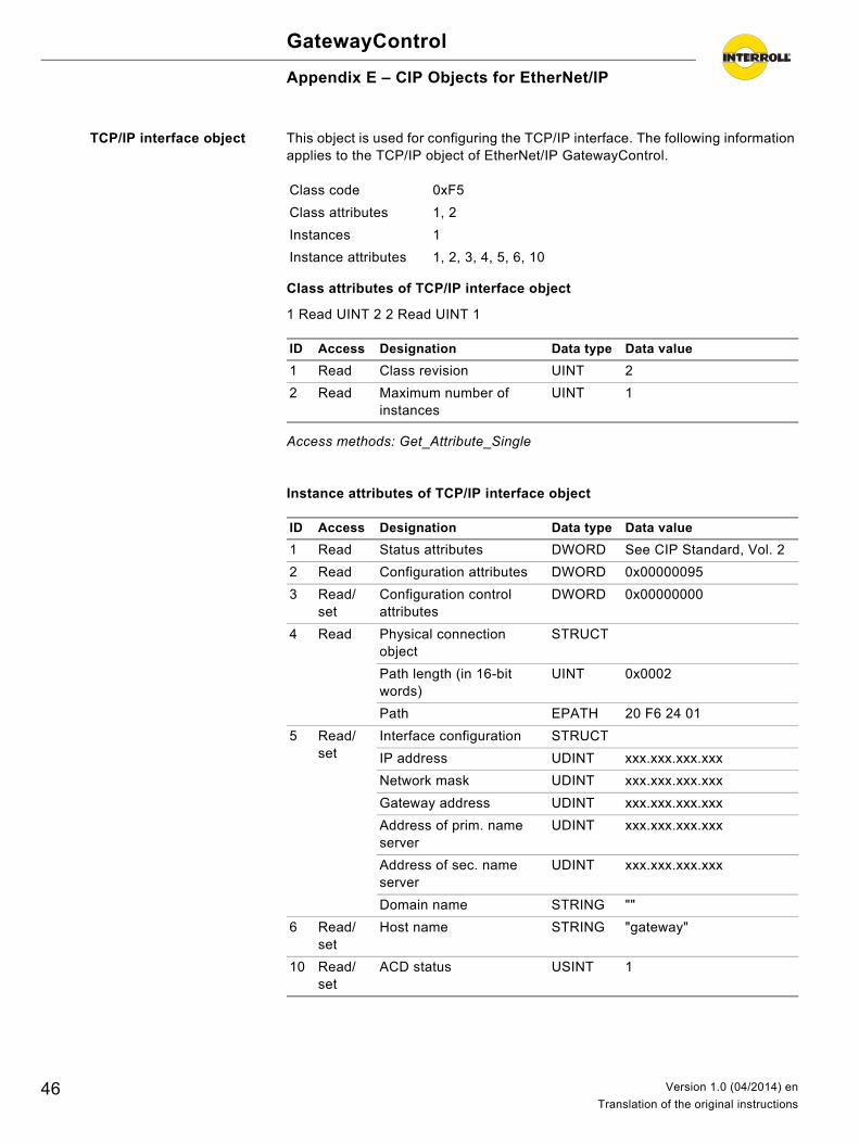
TCP/IP interface object This object is used for configuring the TCP/IP interface. The following information applies to the TCP/IP object of EtherNet/IP GatewayControl.
Class attributes of TCP/IP interface object
1 Read UINT 2 2 Read UINT 1
Access methods: Get_Attribute_Single
Instance attributes of TCP/IP interface object
Class code 0xF5
Class attributes 1, 2
Instances 1
Instance attributes 1, 2, 3, 4, 5, 6, 10
ID Access Designation Data type Data value
1 Read Class revision UINT 2
2 Read Maximum number of instances
UINT 1
ID Access Designation Data type Data value
1 Read Status attributes DWORD See CIP Standard, Vol. 2
2 Read Configuration attributes DWORD 0x00000095
3 Read/set
Configuration control attributes
DWORD 0x00000000
4 Read Physical connection object
STRUCT
Path length (in 16-bit words)
UINT 0x0002
Path EPATH 20 F6 24 01
5 Read/set
Interface configuration STRUCT
IP address UDINT xxx.xxx.xxx.xxx
Network mask UDINT xxx.xxx.xxx.xxx
Gateway address UDINT xxx.xxx.xxx.xxx
Address of prim. name server
UDINT xxx.xxx.xxx.xxx
Address of sec. name server
UDINT xxx.xxx.xxx.xxx
Domain name STRING ""
6 Read/set
Host name STRING "gateway"
10 Read/set
ACD status USINT 1
46 Version 1.0 (04/2014) en
Translation of the original instructions
GatewayControl
Appendix E – CIP Objects for EtherNet/IP
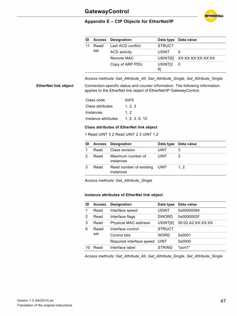
Access methods: Get_Attribute_All, Get_Attribute_Single, Set_Attribute_Single
EtherNet link object Connection-specific status and counter information. The following information applies to the EtherNet link object of EtherNet/IP GatewayControl.
Class attributes of EtherNet link object
1 Read UINT 3 2 Read UINT 2 3 UINT 1,2
Access methods: Get_Attribute_Single
Instance attributes of EtherNet link object
Access methods: Get_Attribute_All, Get_Attribute_Single, Set_Attribute_Single
11 Read/set
Last ACD conflict STRUCT
ACD activity USINT 0
Remote MAC USINT[6] XX:XX:XX:XX:XX:XX
Copy of ARP PDU USINT[28]
0
ID Access Designation Data type Data value
Class code 0xF6
Class attributes 1, 2, 3
Instances 1, 2
Instance attributes 1, 2, 3, 6, 10
ID Access Designation Data type Data value
1 Read Class revision UINT 3
2 Read Maximum number of instances
UINT 2
3 Read Read number of existing instances
UINT 1, 2
ID Access Designation Data type Data value
1 Read Interface speed UDINT 0x00000064
2 Read Interface flags DWORD 0x0000002F
3 Read Physical MAC address USINT[6] 00:02:A2:XX:XX:XX
6 Read/set
Interface control STRUCT
Control bits WORD 0x0001
Required interface speed UINT 0x0000
10 Read Interface label STRING "port1"
47Version 1.0 (04/2014) en
Translation of the original instructions
GatewayControl
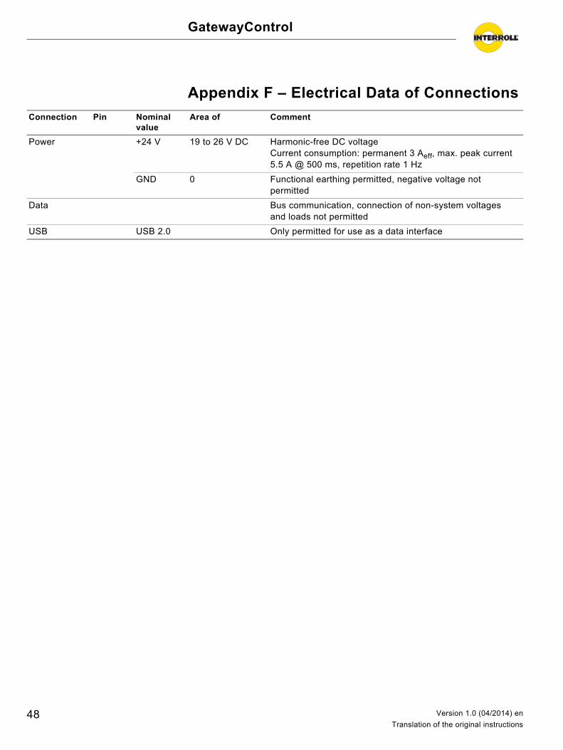
Appendix F – Electrical Data of Connections
Connection Pin Nominal value
Area of Comment
Power +24 V 19 to 26 V DC Harmonic-free DC voltageCurrent consumption: permanent 3 Aeff, max. peak current 5.5 A @ 500 ms, repetition rate 1 Hz
GND 0 Functional earthing permitted, negative voltage not permitted
Data Bus communication, connection of non-system voltages and loads not permitted
USB USB 2.0 Only permitted for use as a data interface
48 Version 1.0 (04/2014) en
Translation of the original instructions
GatewayControl
Appendix G – Glossary of ParametersPB1 BusType: A GatewayControl was selected via the Map step. PB1 designates the
fieldbus selected with it. The parameter value cannot be changed.
PB2 BusBitrate: Transfer speed of Profibus (Profibus only).
Default is Autodetect.
PB3 BusAddress: The GatewayControl is a Profibus node. The Profibus node address intended for the GatewayControl Profibus must be entered here.
Default is 5.
PB4 HostName: Name of the GatewayControl in the network (Profinet, EtherNet/IP).
Default is Gateway.
This name must match the name specified in the PLC.
PB5 IPAddress: Internet protocol address of the GatewayControl in the network (Profinet, EtherNet/IP).
Default is 0.0.0.0.
PB6 SubnetMask: Definition of the relevant bits for the network prefix of the Internet protocol address (Profinet, EtherNet/IP).
Default is 0.0.0.0.
PB7 BroadcastAddress: Broadcast address of the GatewayControl in the Internet protocol subnet (Profinet, EtherNet/IP).
Default is 0.0.0.0.
PB8 BusErrorResponse: Response of the system in case of transmission interruptions on the fieldbus or faults in the PLC (Profibus, Profinet, EtherNet/IP).
• LED display: Conveyor remains in operating state. The error is indicated via fault LED. The LED fault display is automatically reset once the fault has been removed.
• System stops: Conveyor is being stopped. The error is indicated via fault LED. The LED fault display is automatically reset and the system automatically returns to operation once the fault has been removed.
• System error: Conveyor is being stopped and changes to the System error state. The error is indicated via fault LED. The system error can be reset only via voltage reset.
Default is System stops.
PB10 DomainName: Domain name of the GatewayControl in the Internet Domain Name System (DNS) (EtherNet/IP only).
Default: ""
PB11 DNS ServerAddress: IP address of the primary DNS server responsible for the name resolution (EtherNet/IP only).
Default is 0.0.0.0
PB12 DNS ServerAddress2: IP address of the alternate DNS server responsible for the name resolution (EtherNet/IP only).
Default is 0.0.0.0
49Version 1.0 (04/2014) en
Translation of the original instructions
GatewayControl
Appendix G – Glossary of Parameters
PB13 NetworkConfigMode: Procedure for the network settings (EtherNet/IP only).
• Static: Settings are made via the Configurator (PB4, PB5, PB6, PB7, PB10, PB11, PB12)
• BOOTP: Settings are made via network using a BOOTP server (PB4, PB5, PB6, PB7, PB10, PB11, PB12)
• DHCP: Settings are made via network using a DHCP server (PB4, PB5, PB6, PB7, PB10, PB11, PB12)
Default is DHCP
PB14 Port setting: Operating mode and transfer speed of the Ethernet port (EtherNet/IP only).
• HalfDuplex 10 Mbps: Half-duplex transmission with 10 Megabit per second• FullDuplex 10 Mbps: Full-duplex transmission with 10 Megabit per second• HalfDuplex 100 Mbps: Half-duplex transmission with 100 Megabit per second• FullDuplex 100 Mbps: Full-duplex transmission with 100 Megabit per second• Auto: Automatic configuration of Ethernet port
Default is Auto
PG1 ControlMode: Control operating mode of the ConveyorControl system (Profibus, Profinet, EtherNet/IP).
• I/O PLC control: The control of the conveyor process is done decentrally in the ConveyorControl modules. The PLC can monitor errors and the conveyor process and affect it by setting global or zone-based control signals (signals correspond to the selection under PIN4)
• Complete PLC control: Control is done exclusively via PLC; for this purpose, it receives the status messages of sensors and RollerDrive. The ConveyorControl modules serve only as decentral I/O module.
Default is I/O PLC control.
ProductKey If the Configurator is connected with the ConveyorControl, the Interroll article number is displayed for the selected module.
Serial If the Configurator is connected with the ConveyorControl, the Interroll serial number is displayed for the selected module.
MACAddress Ethernet hardware address of GatewayControl (read value only). The address is displayed only if a USB connection exists to the GatewayControl and the ConveyorControl modules have been addressed.
50 Version 1.0 (04/2014) en
Translation of the original instructions
GatewayControl
Appendix H – Installation Declaration
Installation declaration
in accordance with the EC Machinery Directive 2006/42/EC, Appendix II B
The manufacturer:
hereby declares with sole responsibility that the product range
• GatewayControl
is not a ready-to-use machine as defined by the EC Machinery Directive and, therefore, does not fully comply with the requirements of this directive. The commissioning of these conveyor modules is not permitted unless conformity of the entire machine/system in which they are installed has been declared in compliance with the EC Machinery Directive.
The health and safety requirements as stated in Appendix I have been applied. The special technical documents mentioned in Appendix VII B have been prepared and will be sent to the responsible authority if necessary.
Person authorized to prepare the technical documents: Interroll Engineering GmbH, Hoeferhof 16, D - 42929 Wermelskirchen
Applicable EC directives:• Machinery Directive 2006/42/EC• EMC Directive 2004/108/EC• RoHS Directive 2002/95/EC
Applicable harmonized standards:• EN ISO 12100-03 "Safety of machinery - Basic concepts - risk assessment
and reduction"
Wermelskirchen, 31 September 2013
Armin Lindholm
(Managing Director)
(This declaration can be obtained at www.interroll.com, if needed.)
Interroll Engineering GmbH Hoeferhof 16 D - 42929 WermelskirchenGermany
51Version 1.0 (04/2014) en
Translation of the original instructions

©copyright
Version 1.0 (04/2014) en For your local contacts please visit
Translation of the original instructions interroll.com/contacts