Embed Size (px)
Citation preview
GSK980T
Turning Machine CNC System
User Manual
GSK980T CNC SYSTEM USER MANUAL
GUANGZHOU CNC EQUIPMENT CO., LTD.
Ⅰ INTRODUCTION······························································································································1
1.1 Introduction································································································································· 1
1.2 Type Signification························································································································ 1
1.3 Type Table ··································································································································· 1
II. Programming ······································································································································2
2.1 General······································································································································ 2 2.1.1 Axes Definition ·················································································································· 2 2.1.2 Reference Point (Machine Zero Point) ··············································································· 2 2.1.3 Coordinate value and direction and dimension··································································· 2 2.1.4 Unit and Range of coordinate ····························································································· 3 2.1.5 Initial and Modal Status of the Command ·········································································· 3 2.1.6 The Start of a Program········································································································ 3 2.1.7 The End of a Program········································································································· 3 2.1.8 Program Configuration······································································································· 3 2.1.9 Program Configuration······································································································· 3
2.2 controlled Axis ·························································································································· 5 2.2.1 Number of Controlled Axis ································································································ 5 2.2.2 Unit Setting ························································································································ 5 2.2.3 Maximum Strokes ·············································································································· 5
2.3 Preparatory Function (G Function)···························································································· 6 2.3.1 Positioning(G00) ················································································································ 7 2.3.2 Linear Interpolation (G01)·································································································· 7 2.3.3 Circular Interpolation (G02,G03) ······················································································· 8 2.3.4 Thread Cutting (G32) ······································································································· 11 2.3.5 Return to Reference Point Automatically (G28) ······························································· 14 2.3.6 Dwell(G04) ······················································································································ 14 2.3.7 Work Coordinate System Setting(G0) ·············································································· 14 2.3.8 Feed per Minute (G98) ····································································································· 15 2.3.9 Feed per Revolution(G99) ································································································ 15 2.3.10 Constant Surface Speed Control(G96, G97)··································································· 17 2.3.11 Canned Cycle(G90, G92 G94)························································································ 20 2.3.12 Multiple Repetitive Cycle (G70~G75) ··········································································· 25 2.3.13 Notes on Multiple Repetitive Cutting Cycle (G70~G75)················································ 34
2.4 Spindle Function(S Function)·································································································· 34 2.4.1 Spindle Speed Command·································································································· 34
2.5 Tool Function·························································································································· 35 2.5.1 Procedures of tool Change································································································ 35 2.5.2 Tool selection (Change) Related Parameters ···································································· 36
2.6 Auxiliary Function(M function) ······························································································ 36 2.6.1 Description of M F unction ······························································································ 37 2.6.2 M function Related Data··································································································· 37
2.7 Program Configuration············································································································ 39 2.7.1 Program···························································································································· 39 2.7.2 Program Number ·············································································································· 41
GSK980T CNC SYSTEM USER MANUAL
GUANGZHOU CNC EQUIPMENT CO., LTD.
2.7.3 Sequence Number and Block···························································································· 42 2.7.4 Word and Address ············································································································ 42 2.7.5 Basic Addresses and Ranges of Command Values···························································· 43 2.7.6 End of Program ················································································································ 43
2.8 Coordinate Values and Dimensions························································································· 43 2.8.1 Absolute Commands and Incremental Commands ··························································· 43 2.8.2 Decimal Point Programming ···························································································· 45 2.8.3 Diameter Designation and Radius Designation ································································ 45
2.9 Tool Offset ······························································································································ 46 2.9.1 Geometry Tool Offset ······································································································· 46 2.9.2 T Code for Tool offset ······································································································ 46 2.9.3 Tool Offset Value Input by Moving the Tool To a Fixed Point ········································· 47 2.9.4 Direct Input of Tool Offset by Trial Cutting ····································································· 47
2.10 Automatic Acceleration and Deceleration ············································································· 49 2.10.1 Speed Control In the Corner Between Blocks ··································································· 50
2.11 The Macro Program to User ·································································································· 50 2.11.1 The Macro Command ········································································································ 51 2.11.2 The Macro Program Body ······························································································ 51 2.11.3 Operation and Transfer Dictate(G65) ··········································································· 52 2.11.4 The Note about the Macro Program Body ······································································ 54 2.11.5 Example for User··············································································································· 55
III. Operation ·········································································································································56
3.1 Operation Panel······················································································································· 56 3.1.1 LCD/MDI Panel ··············································································································· 56 3.1.2 Screen Change Keys········································································································· 57 3.1.3 Explanation of Key Board ································································································ 57 3.1.4 Machine Operation Panel ································································································· 58
3.2 Manual Operation···················································································································· 59 3.2.1 Manual Reference Point Return························································································ 59 3.2.2 Manual start Point Return································································································· 59 3.2.3 Manual Continuous Feed·································································································· 60 3.2.4 Step Feed·························································································································· 61 3.2.5 Manual Handle Feed (Optional function) ········································································· 62 3.2.6 Manual auxiliary operation······························································································· 62
3.3 Automatic Operation ··············································································································· 64 3.3.1 Automatic Operation mode ······························································································ 64 3.3.2 Starting Automatic Operation ··························································································· 65 3.3.3 Executing Automatic Operation ······················································································· 65 3.3.4 Stopping and Terminating Memory Operation ································································· 65
3.4 TEST OPERATION················································································································ 67 3.4.1 All Axis Machine Lock ···································································································· 67 3.4.2 Auxiliary Function Lock ·································································································· 67 3.4.3 Feedrate Override ············································································································· 67 3.4.4 Rapid Traverse Override··································································································· 68 3.4.5 Dry Running····················································································································· 68 3.4.6 Restart After Feed Hold···································································································· 68
GSK980T CNC SYSTEM USER MANUAL
GUANGZHOU CNC EQUIPMENT CO., LTD.
3.4.7 Single Block ····················································································································· 68
3.5 Safety Operation······················································································································ 69 3.5.1 Emergency Operation······································································································· 69 3.5.2 Overtravel························································································································· 70
3.6 Alarm ······································································································································ 70
3.7 Program Storage & Edit ······································································································· 70 3.7.1 Preparation for Part Program Storage & Edit Operation ················································ 70 3.7.2 Registering Program to Memory ······················································································ 70 3.7.3 Program Number Searching ····························································································· 71 3.7.4 Deleting Program ············································································································· 71 3.7.5 Deleting All Program········································································································ 71 3.7.6 Output a program ············································································································· 72 3.7.7 Output All Programs········································································································· 72 3.7.8 Sequence Number Search································································································· 72 3.7.9 Inserting, Amending and Deleting of word······································································· 73 3.7.10 Number of Registered Programs····················································································· 76 3.7.11 Capacity of System Memory ·························································································· 76
3.8 Display and Setting Data ········································································································· 76 3.8.1 Offset Amount ·················································································································· 76 3.8.2 The setting of setting parameter························································································ 77 3.8.3 The Setting and Display of Custom Macro Variable························································· 79 3.8.4 Parameter ························································································································· 80 3.8.5 Diagnoses ························································································································· 82
3.9 Display ···································································································································· 82 3.9.1 Status display···················································································································· 82 3.9.2 Display of key in data······································································································· 83 3.9.3 Program Number, Sequence Number Display ·································································· 83 3.9.4 The Display of Program Memory Used.··········································································· 84 3.9.5 Display of Command Value ([PRG] key) ········································································· 84 3.9.6 Current position display ([POS] key) ··············································································· 85 3.9.7 Display of Run Time and Parts Count ·············································································· 86 3.9.8 Alarm Display([ALM] key)······························································································ 86 3.9.9 Adjusting Brightness of LCD ··························································································· 87
IV CONNECTION ·································································································································88
4.1 SYSTEM CONNECTION DIAGRAM··················································································· 88 4.1.1 Layout diagram of interfaces ···························································································· 88 4.1.2 Descriptions of Interfaces································································································· 88 4.1.3 Connection Diagram········································································································· 89
4.2 Detail of connection ················································································································ 89 4.2.1 From CNC to Axis Driver ································································································ 89 4.2.2 Description of Signal········································································································ 90
4.3 Connection between CNC and Axis Driver············································································· 92
4.4 Spindle Encoder ······················································································································ 93
4.5 RS232-C Serial Interface(Optional) ························································································ 93
GSK980T CNC SYSTEM USER MANUAL
GUANGZHOU CNC EQUIPMENT CO., LTD.
4-6 Spindle Analogue Control Interface(Optional) ······································································· 94
4-7 Handwheel ······························································································································ 94
4.8 Connection of power supply···································································································· 95
4.9 In put/output Interface ············································································································· 96 4.9.1 Connecting Diagram········································································································· 96 4.9.2 Input Signals····················································································································· 96 4.9.3 Signal Description ············································································································ 97 4.9.4 Output Signal ················································································································· 100 4.9.5 Diagnose Address Table of Input and Output Signal ······················································ 101
V Adjustment of Machine ····················································································································102
5.1 Preparation before Power On ································································································ 102
5.2 Adjustment of Machine ········································································································· 102 5.2.1 Emergency Stop Button·································································································· 102 5.2.2 Adjustment of Drive Axis······························································································· 102 5.2.3 Toolpost Adjustment······································································································· 104 5.2.4 Spindle Adjustment ········································································································ 104 5.2.5 Single step/ Handle Feed ································································································ 104 5.2.6 Others Adjustment·········································································································· 104
5.3 Standard Parameter Setting and the Storage of Parameter, Diagnosis and Program ·············· 105
Appendix Ⅰ Parameter ·····················································································································106
Appendix II Diagnosis ·························································································································114
Appendix III Alarm Code List ·············································································································119
Appendix IV Binary to Decimal Conversion Table·············································································122
Appendix V Installation dimension ········································································································· I
GSK980T CNC SYSTEM USER MANUAL
GUANGZHOU CNC EQUIPMENT CO., LTD. 1
Production symbol of GSK
Ⅰ INTRODUCTION
1.1 Introduction
GSK980T is a well-pervading machine numerical-controlled system produced by my factory. As a upgrading production of the economical CNC,GSK980T has following characteristic:
△ Adopting 16-bit CPU,CPLD and hardware interpolation to realize high-speed and um level control
△ Adopting 4-layer PCB and having high integration, reasonable technology and high reliability
△ Having Chinese display with LCD and friendly interface, convenient operation △ Being able to adjusting accelerating or decelerating speed, matching step- motor or servo
motor △ Being able to adjust the ratio of electronic gear and having convenient application
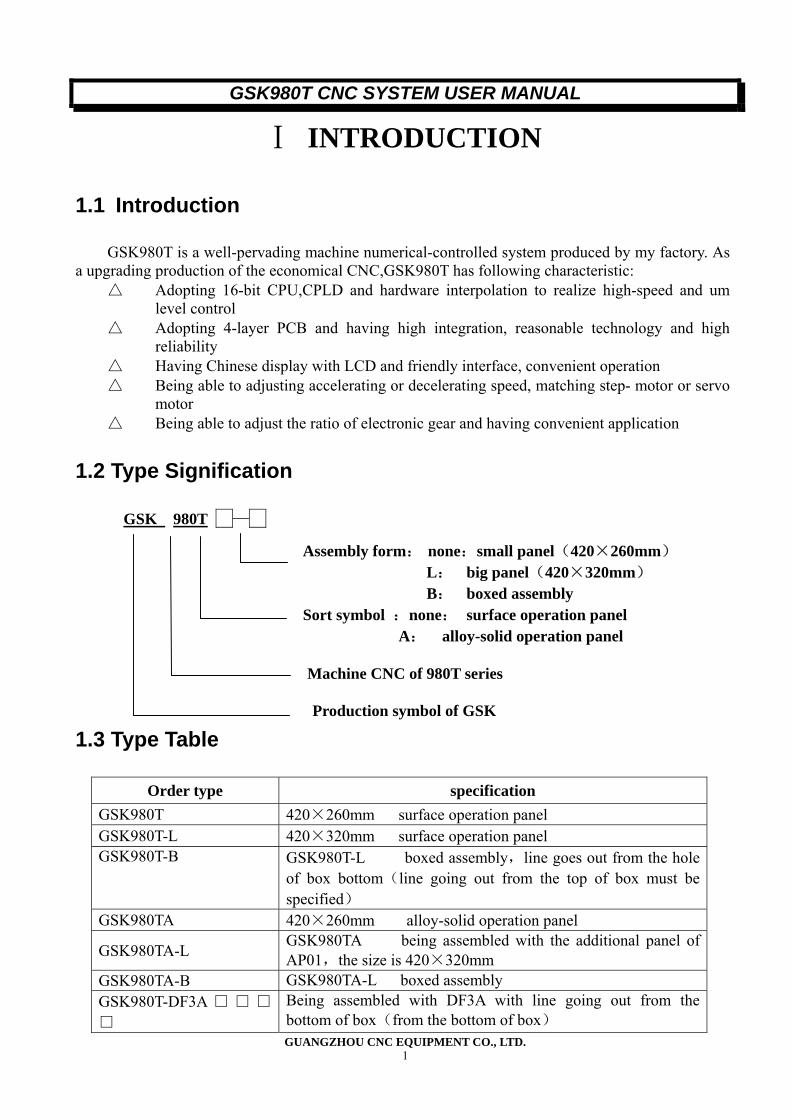
1.2 Type Signification
GSK 980T — 。
Assembly form: none:small panel(420×260mm) L: big panel(420×320mm) B: boxed assembly Sort symbol :none: surface operation panel A: alloy-solid operation panel
Machine CNC of 980T series
1.3 Type Table
Order type specification GSK980T 420×260mm surface operation panel GSK980T-L 420×320mm surface operation panel GSK980T-B GSK980T-L boxed assembly,line goes out from the hole
of box bottom(line going out from the top of box must be specified)
GSK980TA 420×260mm alloy-solid operation panel
GSK980TA-L GSK980TA being assembled with the additional panel of AP01,the size is 420×320mm
GSK980TA-B GSK980TA-L boxed assembly GSK980T-DF3A □ □ □
□ Being assembled with DF3A with line going out from the bottom of box(from the bottom of box)
GSK980T CNC SYSTEM USER MANUAL
GUANGZHOU CNC EQUIPMENT CO., LTD. 2
GSK980T-DF3A □ □ □
□-B Being assembled with DF3A with line going out from back(from aerial socket in the back of box)
GSK980T-DY3□□□□-B
Being assembled with DY3 with line going out from back(from aerial socket in the back of box)
GSK980T-DY3□□□□ Being assembled with DY3 with line going out from the bottom of box(from the bottom of box)
Note :“□□□□”is 4-bit digit. the first 2-bit means the specification of driver in X axis, the second 2-bit means the specification of driver in Z axis. “00” means no driver being assembled in that axis.
II. Programming
2.1 General
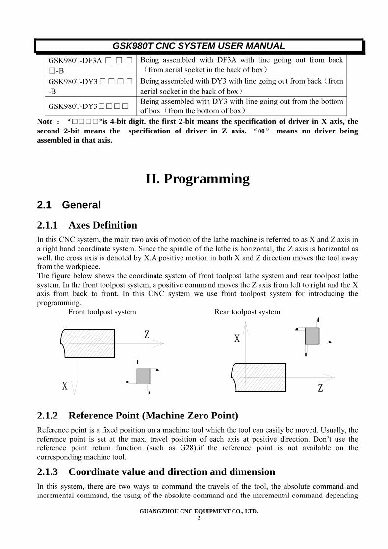
2.1.1 Axes Definition In this CNC system, the main two axis of motion of the lathe machine is referred to as X and Z axis in a right hand coordinate system. Since the spindle of the lathe is horizontal, the Z axis is horizontal as well, the cross axis is denoted by X.A positive motion in both X and Z direction moves the tool away from the workpiece. The figure below shows the coordinate system of front toolpost lathe system and rear toolpost lathe system. In the front toolpost system, a positive command moves the Z axis from left to right and the X axis from back to front. In this CNC system we use front toolpost system for introducing the programming. Front toolpost system Rear toolpost system
Z
X Z
X
2.1.2 Reference Point (Machine Zero Point) Reference point is a fixed position on a machine tool which the tool can easily be moved. Usually, the reference point is set at the max. travel position of each axis at positive direction. Don’t use the reference point return function (such as G28).if the reference point is not available on the corresponding machine tool.
2.1.3 Coordinate value and direction and dimension In this system, there are two ways to command the travels of the tool, the absolute command and incremental command, the using of the absolute command and the incremental command depending
GSK980T CNC SYSTEM USER MANUAL
GUANGZHOU CNC EQUIPMENT CO., LTD. 3
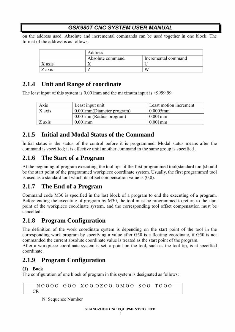
on the address used. Absolute and incremental commands can be used together in one block. The format of the address is as follows:
Address Absolute command Incremental command X axis X U Z axis Z W
2.1.4 Unit and Range of coordinate The least input of this system is 0.001mm and the maximum input is ±9999.99.
2.1.5 Initial and Modal Status of the Command Initial status is the status of the control before it is programmed. Modal status means after the command is specified; it is effective until another command in the same group is specified .
2.1.6 The Start of a Program At the beginning of program executing, the tool tips of the first programmed tool(standard tool)should be the start point of the programmed workpiece coordinate system. Usually, the first programmed tool is used as a standard tool which its offset compensation value is (0,0).
2.1.7 The End of a Program Command code M30 is specified in the last block of a program to end the executing of a program. Before ending the executing of grogram by M30, the tool must be programmed to return to the start point of the workpiece coordinate system, and the corresponding tool offset compensation must be cancelled.
2.1.8 Program Configuration The definition of the work coordinate system is depending on the start point of the tool in the corresponding work program by specifying a value after G50 is a floating coordinate, if G50 is not commanded the current absolute coordinate value is treated as the start point of the program. After a workpiece coordinate system is set, a point on the tool, such as the tool tip, is at specified coordinate.
2.1.9 Program Configuration (1) Bock The configuration of one block of program in this system is designated as follows:
N: Sequence Number
Axis Least input unit Least motion increment 0.001mm(Diameter program) 0.0005mm X axis 0.001mm(Radius program) 0.001mm
Z axis 0.001mm 0.001mm
N O O O O G O O X O O .O Z O O . O M O O S O O T O O O CR
GSK980T CNC SYSTEM USER MANUAL
GUANGZHOU CNC EQUIPMENT CO., LTD. 4
G: Preparatory Function X,Z: Dimension word M: Miscellaneous function S: spindle function T: Tool function CR: End of block
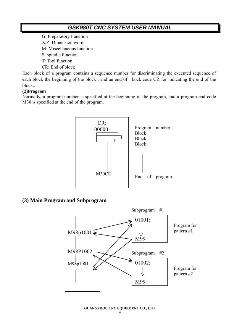
Each block of a program contains a sequence number for discriminating the executed sequence of each block the beginning of the block , and an end of bock code CR for indicating the end of the block.. (2)Program Normally, a program number is specified at the beginning of the program, and a program end code M30 is specified at the end of the program. (3) Main Program and Subprogram
CR: 00000:
M30CR
Program number Block Block Block End of program
M98p1001 M98P1002 M98p1001
01001; M99
01002; M99
Subprogram #1
Program for pattern #1
Subprogram #2
Program for pattern #2
GSK980T CNC SYSTEM USER MANUAL
GUANGZHOU CNC EQUIPMENT CO., LTD. 5
When machining of the same pattern appears at many sections of a workpiece program, a program for this pattern is created first, this is called the subprogram, on the other hand, the original program is called the main program. When a subprogram execution command is executed during the executing of the main program, commands of the subprogram are executed. When the executing of the subprogram is finished, the sequence returns to the main program.
2.2 controlled Axis
2.2.1 Number of Controlled Axis
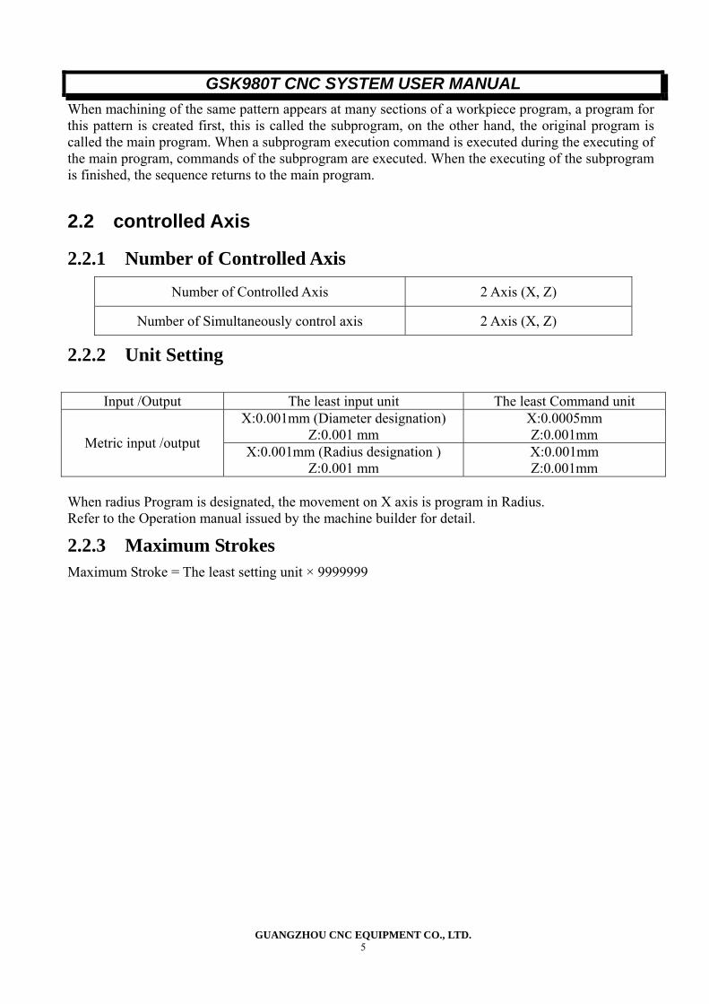
Number of Controlled Axis 2 Axis (X, Z)
Number of Simultaneously control axis 2 Axis (X, Z)
2.2.2 Unit Setting
Input /Output The least input unit The least Command unit X:0.001mm (Diameter designation)
Z:0.001 mm X:0.0005mm Z:0.001mm Metric input /output X:0.001mm (Radius designation )
Z:0.001 mm X:0.001mm Z:0.001mm
When radius Program is designated, the movement on X axis is program in Radius. Refer to the Operation manual issued by the machine builder for detail.
2.2.3 Maximum Strokes Maximum Stroke = The least setting unit × 9999999
GSK980T CNC SYSTEM USER MANUAL
GUANGZHOU CNC EQUIPMENT CO., LTD. 6
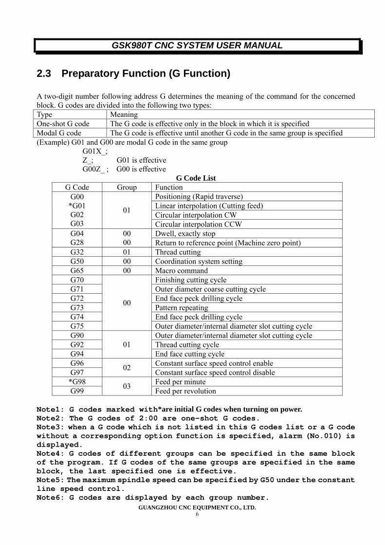
2.3 Preparatory Function (G Function)
A two-digit number following address G determines the meaning of the command for the concerned block. G codes are divided into the following two types: Type Meaning One-shot G code The G code is effective only in the block in which it is specified Modal G code The G code is effective until another G code in the same group is specified (Example) G01 and G00 are modal G code in the same group
G01X_; Z_; G01 is effective G00Z_ ; G00 is effective
G Code List G Code Group Function
Positioning (Rapid traverse) Linear interpolation (Cutting feed) Circular interpolation CW
G00 *G01 G02 G03
01
Circular interpolation CCW Dwell, exactly stop G04
G28 00 00 Return to reference point (Machine zero point)
G32 01 Thread cutting G50 00 Coordination system setting G65 00 Macro command G70 Finishing cutting cycle G71 Outer diameter coarse cutting cycle G72 End face peck drilling cycle G73 Pattern repeating G74 End face peck drilling cycle G75
00
Outer diameter/internal diameter slot cutting cycle G90 Outer diameter/internal diameter slot cutting cycle G92 Thread cutting cycle G94
01 End face cutting cycle
G96 Constant surface speed control enable G97 02 Constant surface speed control disable *G98 Feed per minute G99 03 Feed per revolution
Note1: G codes marked with*are initial G codes when turning on power. Note2: The G codes of 2:00 are one-shot G codes. Note3: when a G code which is not listed in this G codes list or a G code without a corresponding option function is specified, alarm (No.010) is displayed. Note4: G codes of different groups can be specified in the same block of the program. If G codes of the same groups are specified in the same block, the last specified one is effective. Note5: The maximum spindle speed can be specified by G50 under the constant line speed control. Note6: G codes are displayed by each group number.
GSK980T CNC SYSTEM USER MANUAL
GUANGZHOU CNC EQUIPMENT CO., LTD. 7
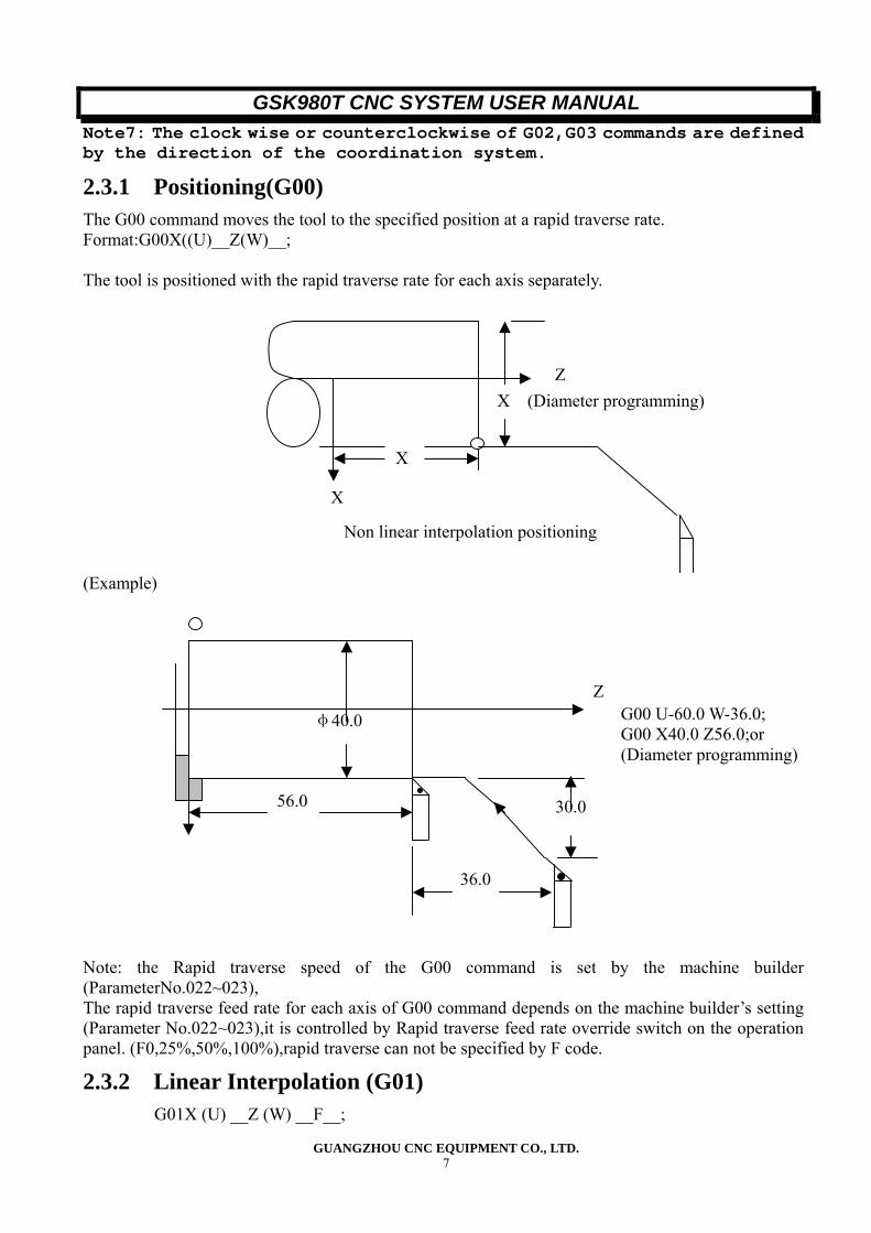
Note7: The clock wise or counterclockwise of G02,G03 commands are defined by the direction of the coordination system.
2.3.1 Positioning(G00) The G00 command moves the tool to the specified position at a rapid traverse rate. Format:G00X((U)__Z(W)__; The tool is positioned with the rapid traverse rate for each axis separately. (Example) Note: the Rapid traverse speed of the G00 command is set by the machine builder (ParameterNo.022~023), The rapid traverse feed rate for each axis of G00 command depends on the machine builder’s setting (Parameter No.022~023),it is controlled by Rapid traverse feed rate override switch on the operation panel. (F0,25%,50%,100%),rapid traverse can not be specified by F code.
2.3.2 Linear Interpolation (G01) G01X (U) __Z (W) __F__;
Z
X
X (Diameter programming)
X
Non linear interpolation positioning
Z
56.0
36.0
30.0
φ40.0 G00 U-60.0 W-36.0; G00 X40.0 Z56.0;or (Diameter programming)
GSK980T CNC SYSTEM USER MANUAL
GUANGZHOU CNC EQUIPMENT CO., LTD. 8
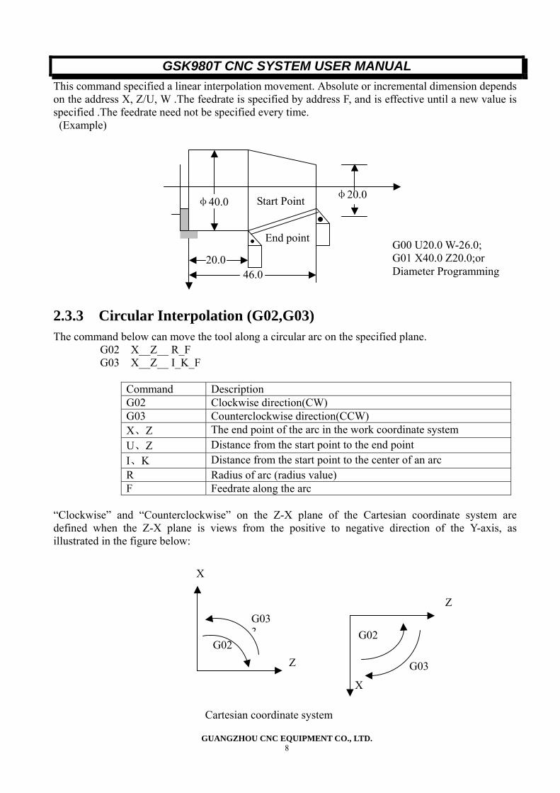
This command specified a linear interpolation movement. Absolute or incremental dimension depends on the address X, Z/U, W .The feedrate is specified by address F, and is effective until a new value is specified .The feedrate need not be specified every time. (Example)
2.3.3 Circular Interpolation (G02,G03) The command below can move the tool along a circular arc on the specified plane.
G02 X__Z__ R_F G03 X__Z__ I_K_F
Command Description G02 Clockwise direction(CW) G03 Counterclockwise direction(CCW) X、Z The end point of the arc in the work coordinate system U、Z Distance from the start point to the end point I、K Distance from the start point to the center of an arc R Radius of arc (radius value) F Feedrate along the arc
“Clockwise” and “Counterclockwise” on the Z-X plane of the Cartesian coordinate system are defined when the Z-X plane is views from the positive to negative direction of the Y-axis, as illustrated in the figure below:
φ40.0
20.0 46.0
φ20.0Start Point
End point G00 U20.0 W-26.0; G01 X40.0 Z20.0;or Diameter Programming
Cartesian coordinate system
G033
G02
X
Z
Z
G02
G03
X
GSK980T CNC SYSTEM USER MANUAL
GUANGZHOU CNC EQUIPMENT CO., LTD. 9
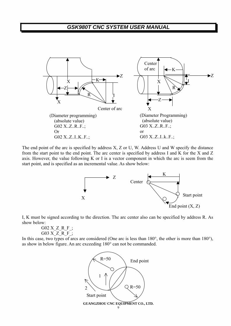
The end point of the arc is specified by address X, Z or U, W. Address U and W specify the distance from the start point to the end point. The arc center is specified by address I and K for the X and Z axis. However, the value following K or I is a vector component in which the arc is seem from the start point, and is specified as an incremental value. As show below: I, K must be signed according to the direction. The arc center also can be specified by address R. As show below:
G02 X_Z_R_F_; G03 X_Z_R_F_;
In this case, two types of arcs are considered (One arc is less than 180°, the other is more than 180°), as show in below figure. An arc exceeding 180° can not be commanded.
K
X
Z X
R
Z
I
X
Z
R I
Z K
Center of arc
X
(Diameter programming) (absolute value) G02 X..Z..R..F..; Or G02 X..Z..I..K..F..;
Center of arc (Diameter Programming) (absolute value) G03 X..Z..R..F..; or G03 X..Z..I..k..F..;
Center K
Start point
End point (X, Z)
Z
X
Start point
R=50 End point
R=50
1
2
GSK980T CNC SYSTEM USER MANUAL
GUANGZHOU CNC EQUIPMENT CO., LTD. 10
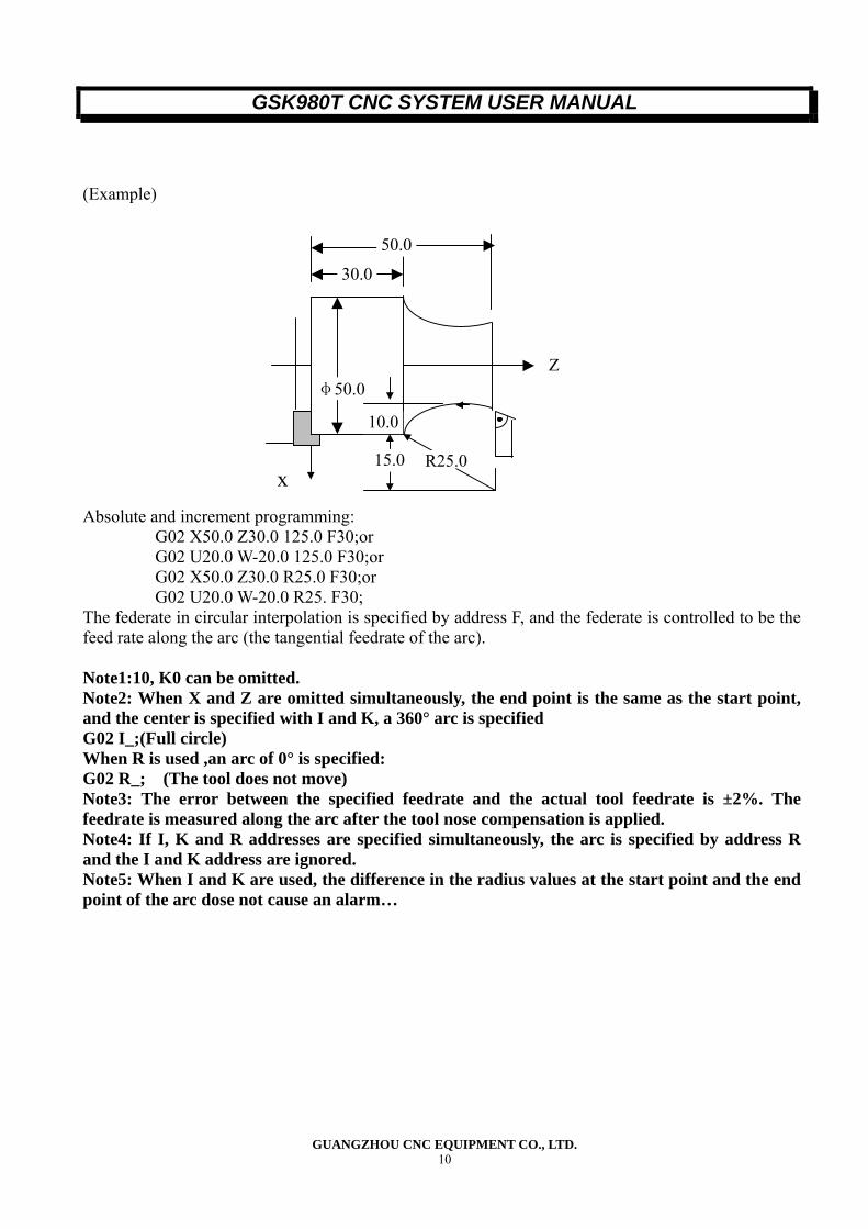
(Example) Absolute and increment programming:
G02 X50.0 Z30.0 125.0 F30;or G02 U20.0 W-20.0 125.0 F30;or G02 X50.0 Z30.0 R25.0 F30;or G02 U20.0 W-20.0 R25. F30;
The federate in circular interpolation is specified by address F, and the federate is controlled to be the feed rate along the arc (the tangential feedrate of the arc). Note1:10, K0 can be omitted. Note2: When X and Z are omitted simultaneously, the end point is the same as the start point, and the center is specified with I and K, a 360° arc is specified G02 I_;(Full circle) When R is used ,an arc of 0° is specified: G02 R_; (The tool does not move) Note3: The error between the specified feedrate and the actual tool feedrate is ±2%. The feedrate is measured along the arc after the tool nose compensation is applied. Note4: If I, K and R addresses are specified simultaneously, the arc is specified by address R and the I and K address are ignored. Note5: When I and K are used, the difference in the radius values at the start point and the end point of the arc dose not cause an alarm…
R25.0
50.0
30.0
Z φ50.0
10.0
15.0x
GSK980T CNC SYSTEM USER MANUAL
GUANGZHOU CNC EQUIPMENT CO., LTD. 11
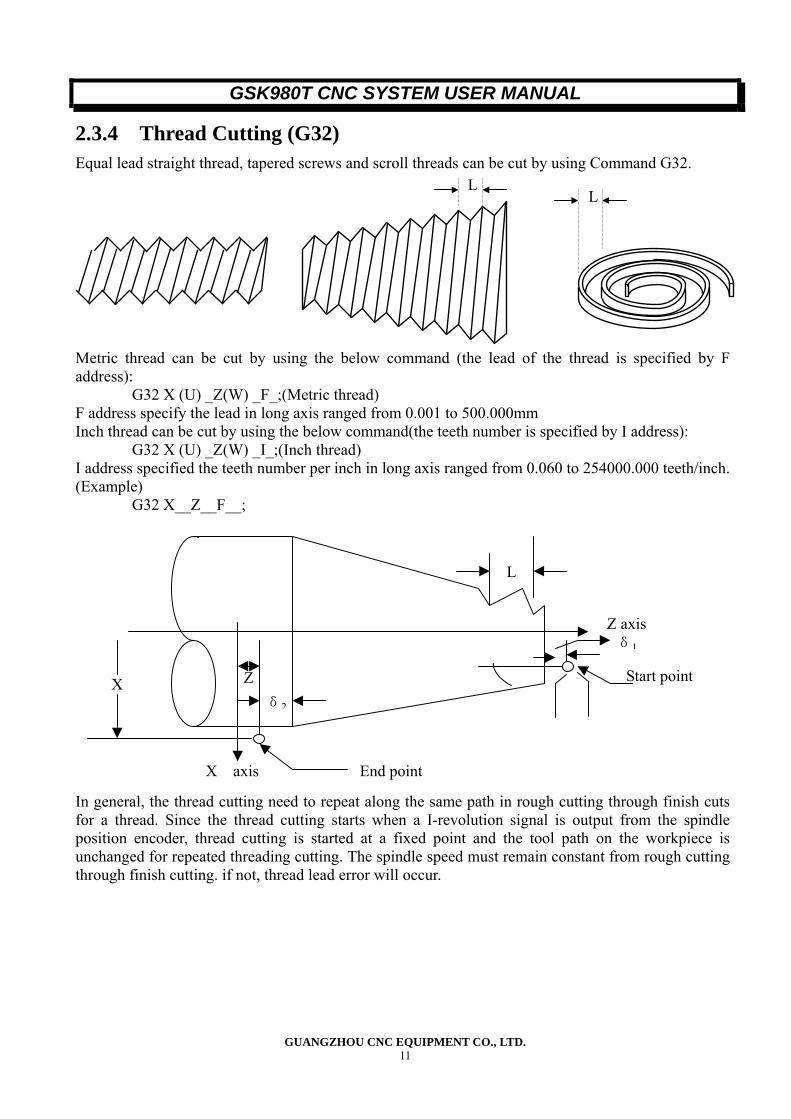
2.3.4 Thread Cutting (G32) Equal lead straight thread, tapered screws and scroll threads can be cut by using Command G32.
Metric thread can be cut by using the below command (the lead of the thread is specified by F address):
G32 X (U) _Z(W) _F_;(Metric thread) F address specify the lead in long axis ranged from 0.001 to 500.000mm Inch thread can be cut by using the below command(the teeth number is specified by I address):
G32 X (U) _Z(W) _I_;(Inch thread) I address specified the teeth number per inch in long axis ranged from 0.060 to 254000.000 teeth/inch. (Example)
G32 X__Z__F__; In general, the thread cutting need to repeat along the same path in rough cutting through finish cuts for a thread. Since the thread cutting starts when a I-revolution signal is output from the spindle position encoder, thread cutting is started at a fixed point and the tool path on the workpiece is unchanged for repeated threading cutting. The spindle speed must remain constant from rough cutting through finish cutting. if not, thread lead error will occur.
LL
L
Z δ2
X
X axis End point
Z axis δ1
Start point
GSK980T CNC SYSTEM USER MANUAL
GUANGZHOU CNC EQUIPMENT CO., LTD. 12
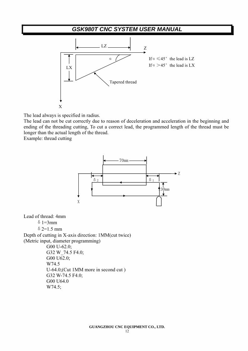
Ifα≤45°the lead is LZ Ifα>45°the lead is LX
LZ
LX
X
Z
Tapered thread
α
The lead always is specified in radius. The lead can not be cut correctly due to reason of deceleration and acceleration in the beginning and ending of the threading cutting, To cut a correct lead, the programmed length of the thread must be longer than the actual length of the thread. Example: thread cutting
30mm
70mm
δ1δ2 Z
X
Lead of thread: 4mm
δ1=3mm δ2=1.5 mm
Depth of cutting in X-axis direction: 1MM(cut twice) (Metric input, diameter programming)
G00 U-62.0; G32 W_74.5 F4.0; G00 U62.0; W74.5 U-64.0;(Cut 1MM more in second cut ) G32 W-74.5 F4.0; G00 U64.0 W74.5;
GSK980T CNC SYSTEM USER MANUAL
GUANGZHOU CNC EQUIPMENT CO., LTD. 13
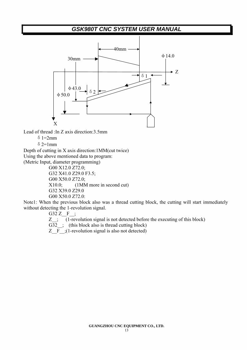
Lead of thread :In Z axis direction:3.5mm δ1=2mm δ2=1mm
Depth of cutting in X axis direction:1MM(cut twice) Using the above mentioned data to program: (Metric Input, diameter programming)
G00 X12.0 Z72.0; G32 X41.0 Z29.0 F3.5; G00 X50.0 Z72.0; X10.0; (1MM more in second cut) G32 X39.0 Z29.0 G00 X50.0 Z72.0:
Note1: When the previous block also was a thread cutting block, the cutting will start immediately without detecting the 1-revolution signal.
G32 Z__F__; Z__; (1-revolution signal is not detected before the executing of this block) G32__; (this block also is thread cutting block) Z__F__;(1-revolution signal is also not detected)
δ2
30mm
40mm
X
φ50.0 φ43.0
δ1Z
φ14.0
GSK980T CNC SYSTEM USER MANUAL
GUANGZHOU CNC EQUIPMENT CO., LTD. 14
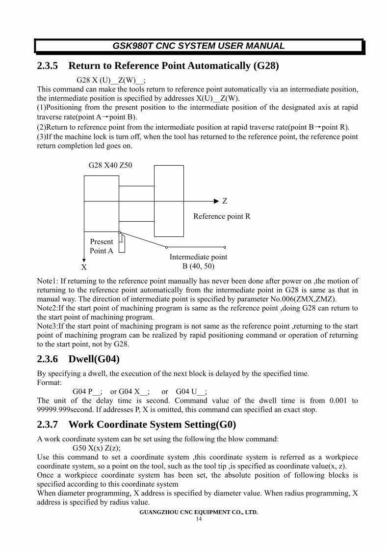
2.3.5 Return to Reference Point Automatically (G28) G28 X (U)__Z(W)__;
This command can make the tools return to reference point automatically via an intermediate position, the intermediate position is specified by addresses X(U)__Z(W). (1)Positioning from the present position to the intermediate position of the designated axis at rapid traverse rate(point A→point B). (2)Return to reference point from the intermediate position at rapid traverse rate(point B→point R). (3)If the machine lock is turn off, when the tool has returned to the reference point, the reference point return completion led goes on. Note1: If returning to the reference point manually has never been done after power on ,the motion of returning to the reference point automatically from the intermediate point in G28 is same as that in manual way. The direction of intermediate point is specified by parameter No.006(ZMX,ZMZ). Note2:If the start point of machining program is same as the reference point ,doing G28 can return to the start point of machining program. Note3:If the start point of machining program is not same as the reference point ,returning to the start point of machining program can be realized by rapid positioning command or operation of returning to the start point, not by G28.
2.3.6 Dwell(G04) By specifying a dwell, the execution of the next block is delayed by the specified time. Format:
G04 P__; or G04 X__; or G04 U__; The unit of the delay time is second. Command value of the dwell time is from 0.001 to 99999.999second. If addresses P, X is omitted, this command can specified an exact stop.
2.3.7 Work Coordinate System Setting(G0) A work coordinate system can be set using the following the blow command:
G50 X(x) Z(z); Use this command to set a coordinate system ,this coordinate system is referred as a workpiece coordinate system, so a point on the tool, such as the tool tip ,is specified as coordinate value(x, z). Once a workpiece coordinate system has been set, the absolute position of following blocks is specified according to this coordinate system When diameter programming, X address is specified by diameter value. When radius programming, X address is specified by radius value.
G28 X40 Z50
Reference point R
Intermediate point B (40, 50)
Present Point A
X
Z
GSK980T CNC SYSTEM USER MANUAL
GUANGZHOU CNC EQUIPMENT CO., LTD. 15
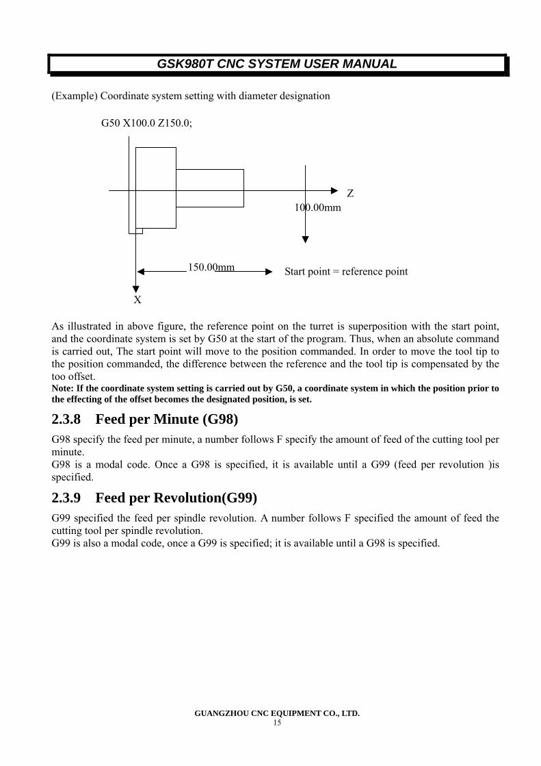
(Example) Coordinate system setting with diameter designation
G50 X100.0 Z150.0;
As illustrated in above figure, the reference point on the turret is superposition with the start point, and the coordinate system is set by G50 at the start of the program. Thus, when an absolute command is carried out, The start point will move to the position commanded. In order to move the tool tip to the position commanded, the difference between the reference and the tool tip is compensated by the too offset. Note: If the coordinate system setting is carried out by G50, a coordinate system in which the position prior to the effecting of the offset becomes the designated position, is set.
2.3.8 Feed per Minute (G98) G98 specify the feed per minute, a number follows F specify the amount of feed of the cutting tool per minute. G98 is a modal code. Once a G98 is specified, it is available until a G99 (feed per revolution )is specified.
2.3.9 Feed per Revolution(G99) G99 specified the feed per spindle revolution. A number follows F specified the amount of feed the cutting tool per spindle revolution. G99 is also a modal code, once a G99 is specified; it is available until a G98 is specified.
Z 100.00mm
Start point = reference point 150.00mm
X
GSK980T CNC SYSTEM USER MANUAL
GUANGZHOU CNC EQUIPMENT CO., LTD. 16
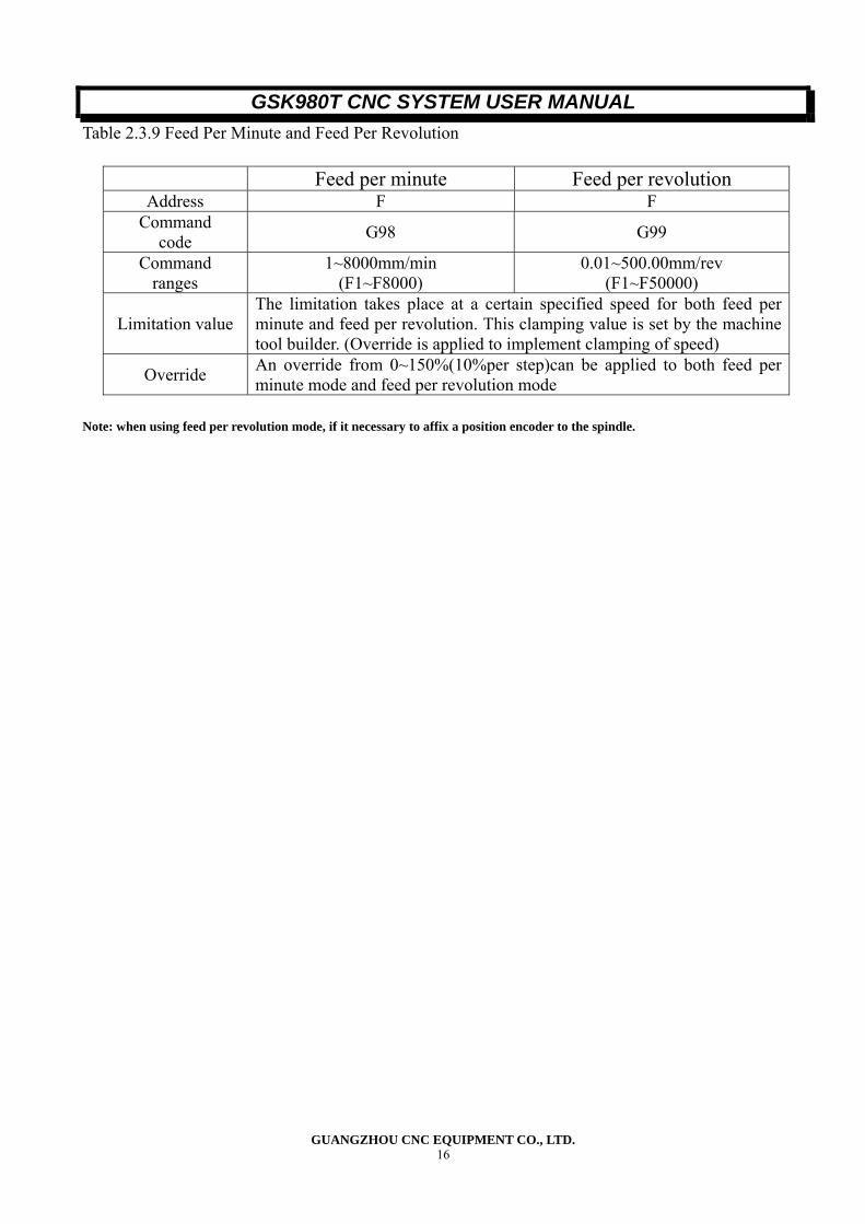
Table 2.3.9 Feed Per Minute and Feed Per Revolution
Feed per minute Feed per revolution Address F F
Command code G98 G99
Command ranges
1~8000mm/min (F1~F8000)
0.01~500.00mm/rev (F1~F50000)
Limitation value The limitation takes place at a certain specified speed for both feed per minute and feed per revolution. This clamping value is set by the machine tool builder. (Override is applied to implement clamping of speed)
Override An override from 0~150%(10%per step)can be applied to both feed per minute mode and feed per revolution mode
Note: when using feed per revolution mode, if it necessary to affix a position encoder to the spindle.
GSK980T CNC SYSTEM USER MANUAL
GUANGZHOU CNC EQUIPMENT CO., LTD. 17
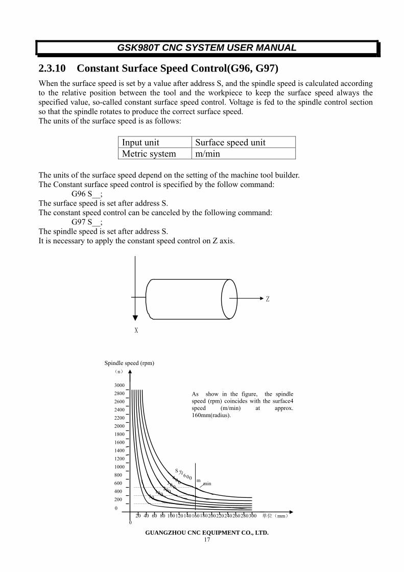
2.3.10 Constant Surface Speed Control(G96, G97) When the surface speed is set by a value after address S, and the spindle speed is calculated according to the relative position between the tool and the workpiece to keep the surface speed always the specified value, so-called constant surface speed control. Voltage is fed to the spindle control section so that the spindle rotates to produce the correct surface speed. The units of the surface speed is as follows:
Input unit Surface speed unit Metric system m/min
The units of the surface speed depend on the setting of the machine tool builder. The Constant surface speed control is specified by the follow command:
G96 S__; The surface speed is set after address S. The constant speed control can be canceled by the following command:
G97 S__; The spindle speed is set after address S. It is necessary to apply the constant speed control on Z axis.
Z
X
20 40 60 80 100120140160180200220240260280300
200
600400
800
12001000
140016001800200022002400260028003000
0
0
0 510 0
2 00
300
400
S为600 m min
As show in the figure, the spindlespeed (rpm) coincides with the surface4speed (m/min) at approx.160mm(radius).
单位(mm)
(n) Spindle speed (rpm)
GSK980T CNC SYSTEM USER MANUAL
GUANGZHOU CNC EQUIPMENT CO., LTD. 18
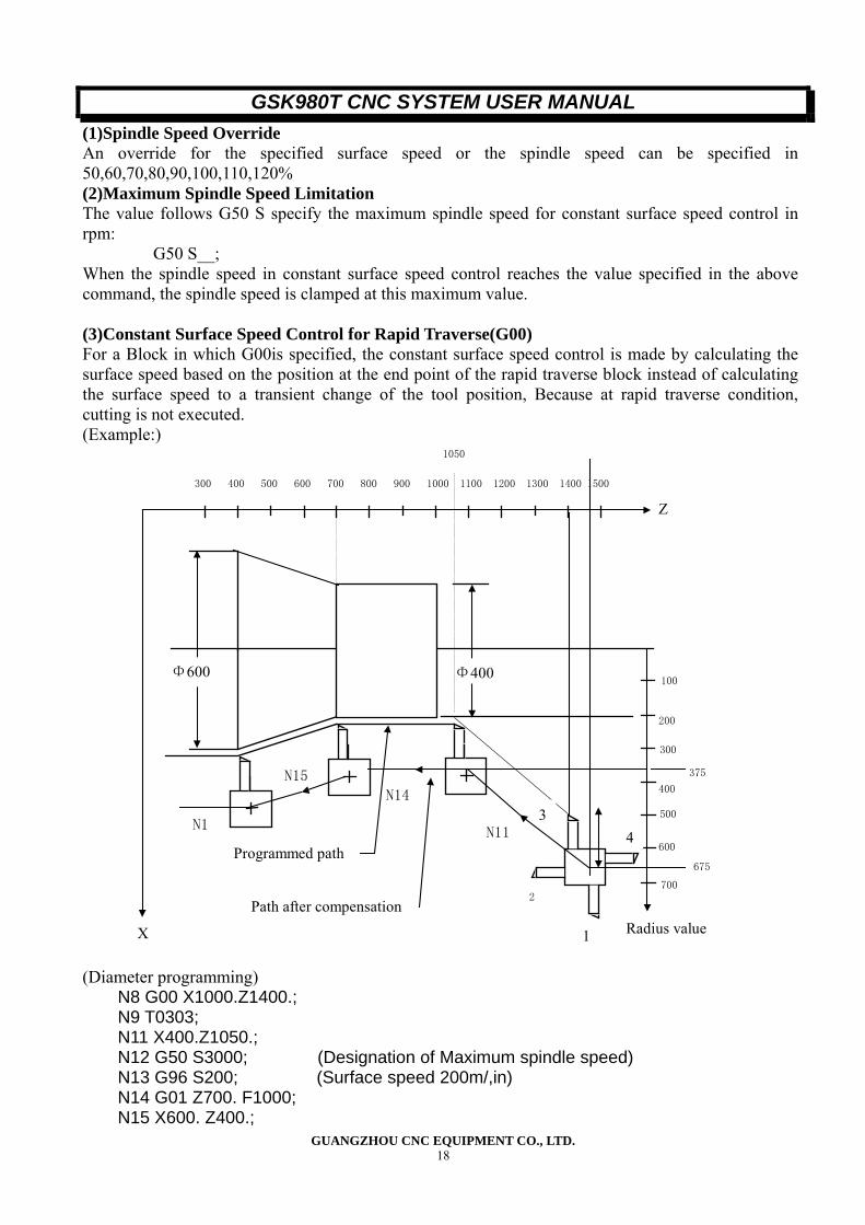
(1)Spindle Speed Override An override for the specified surface speed or the spindle speed can be specified in 50,60,70,80,90,100,110,120% (2)Maximum Spindle Speed Limitation The value follows G50 S specify the maximum spindle speed for constant surface speed control in rpm:
G50 S__; When the spindle speed in constant surface speed control reaches the value specified in the above command, the spindle speed is clamped at this maximum value. (3)Constant Surface Speed Control for Rapid Traverse(G00) For a Block in which G00is specified, the constant surface speed control is made by calculating the surface speed based on the position at the end point of the rapid traverse block instead of calculating the surface speed to a transient change of the tool position, Because at rapid traverse condition, cutting is not executed. (Example:)
1 300 400 500 600 700 800 900 1000 1100 1200 1300 1400 1500
100
200
300
400
600
700
500
Programmed path
Path after compensation 2
Radius value
675
375
Φ400 Φ600
N11
N14
N15
N1
1050
X
Z
1
34
(Diameter programming)
N8 G00 X1000.Z1400.; N9 T0303; N11 X400.Z1050.; N12 G50 S3000; (Designation of Maximum spindle speed) N13 G96 S200; (Surface speed 200m/,in) N14 G01 Z700. F1000; N15 X600. Z400.;
GSK980T CNC SYSTEM USER MANUAL
GUANGZHOU CNC EQUIPMENT CO., LTD. 19
N16 Z....; The CNC use the programmed coordinate value on the X axis to calculate the surface speed. When offset compensation is valid, this is not the value calculated according to the X axis coordinate after offset. At the end point N15 in example above is not the turret center, but the tool nose, that is to say at 600dia, the surface speed is 200m/min. If X axis coordinate value is negative, the CNC uses the absolute value.
GSK980T CNC SYSTEM USER MANUAL
GUANGZHOU CNC EQUIPMENT CO., LTD. 20
2.3.11 Canned Cycle(G90, G92 G94) For repetitive machining peculiar to turning, such as the metal removal in rough cutting, the cutting of the same path is made repetitively, by using these cycles. The said cutting specified in a range of three to several dozen blocks can be specified in one block. In addition, only the values to be changed need to be specified for repetition, the program using this cycle is very simple and useful. The drawings in the examples below are for diameter programming. In radius programming, change U/2 or X/2 to U or X respectively. (1)Outer Diameter/Internal Diameter Cutting Cycle(G90) (a)Cylinder cutting cycle
G90 X (U)__Z(W)__F__;
3(F)
2(F)
1(R)
R:Rapid traverse
F:Cutting feed
U/2
Z
X/2
W
Tool
4(R)
Xaxis
Z axis
In incremental programming, the signs of the numbers following address U and W depend on the direction of paths1 and 2, in the cycle of above figure, the signs of U and W are negative. In single block mode, Operation of 1,2,3,4 are performed by pressing the cycle start key. (b)Taper cutting cycle
G90 X (U)__Z(W)__R__F__;
Tool
Z
X axis
Z axis
R:Rapid traverse
F:Cutting feed
W
RX/2
U/2 1(R)
2(F)
3(F)
4(R)
GSK980T CNC SYSTEM USER MANUAL
GUANGZHOU CNC EQUIPMENT CO., LTD. 21
In incremental programming, the relation between the signs of the numbers following the address U、
W、R, and the tool paths are as follows: 1) U <, W<0, R<0 2) U >0, W<0, R>0
R
W
U/2 1(R)
2(F)
3(F)
4(R)
Z
X
R
W
U/2 1(R)
2(F)
3(F)
4(R)
Z
X
U<0, W<0, R>0 4) U>0, W<0, R<0 But ︱R︱≤︱U/2︱ But ︱R︱≤︱U/2︱
1(R)
4(R)
Z
X
R
W
U/2
2(F)
3(F)
Z
X
R
W
U/2 1(R)
2(F)
3(F)
4(R)
(2) Thread Cutting Cycle (G92) (a) Straight thread cutting
G92X (U)__Z(W)__F__; (Metric thread)
G92X (U)__Z(W)__I__; (Inch thread)
Pitch specified (L)
GSK980T CNC SYSTEM USER MANUAL
GUANGZHOU CNC EQUIPMENT CO., LTD. 22
lead specified (number of teeth/inch)
Note: Address I for inch thread is not a modal command.
U/2
Z
X/2
W
Tool
4(R)
3(R)
2(F)
1(R)
X axis
Z axis
R:Rapid traverse
F:Cutting feel
L
Width of chanferring
In incremental programming, the signs of values of U and W commands depend on the direction of paths 1 and 2. It is to say, if the direction of path 1 is negative along X axis, the value of U is negative. The command of the lead of thread and the limitation of spindle is same with command G32. In single block mode, single block is effective for operation1,2,3,4. The length of the chamfering is set by parameter No.019THDCH. The width of the chamfering is set by parameter No.THDCH*1/10*L (lead of thread) Note 1:As mentioned in Note of G32.And, When the FEED HOLD key is pressed during the execution of the thread cutting block, the feed would not stop until path 3 is finished. (b)Taper Thread Cutting Cycle:
G92 X (U)__Z (W)__R__F__;
G92 X (U)__ Z (W)__R__I__; Note: Address I for inch thread is not a modal command.
Pitch specified (Number of teeth/inch)
lead specified (L)
GSK980T CNC SYSTEM USER MANUAL
GUANGZHOU CNC EQUIPMENT CO., LTD. 23
Z axis
Z W
Tool
4(R)
3(R)
2(F)
1(R)
X axis
R:Rapid traverse
F:Cutting feed
L
U/2
X/2
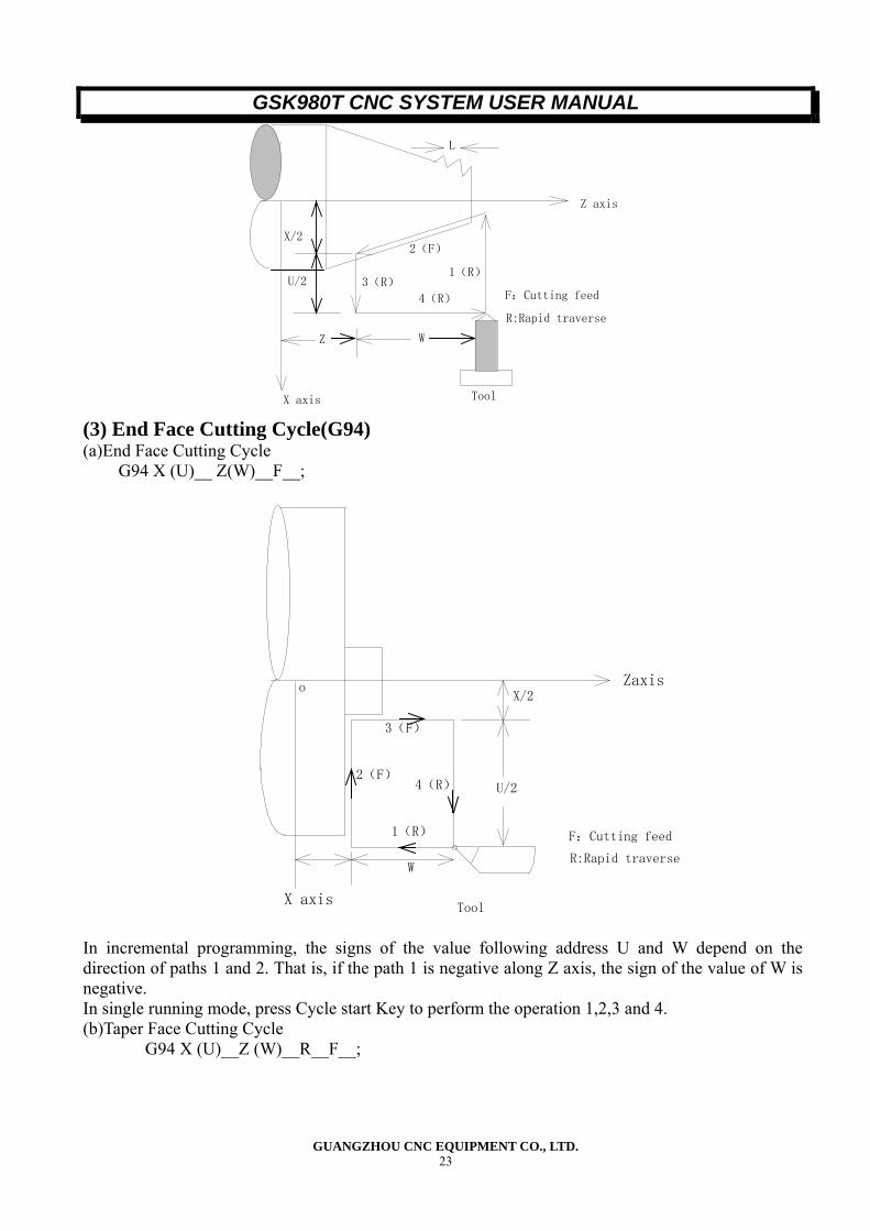
(3) End Face Cutting Cycle(G94) (a)End Face Cutting Cycle
G94 X (U)__ Z(W)__F__;
U/2
X/2
W
Tool
4(R)
3(F)
2(F)
1(R)
X axis
Zaxis
R:Rapid traverse
F:Cutting feed
o
In incremental programming, the signs of the value following address U and W depend on the direction of paths 1 and 2. That is, if the path 1 is negative along Z axis, the sign of the value of W is negative. In single running mode, press Cycle start Key to perform the operation 1,2,3 and 4. (b)Taper Face Cutting Cycle
G94 X (U)__Z (W)__R__F__;
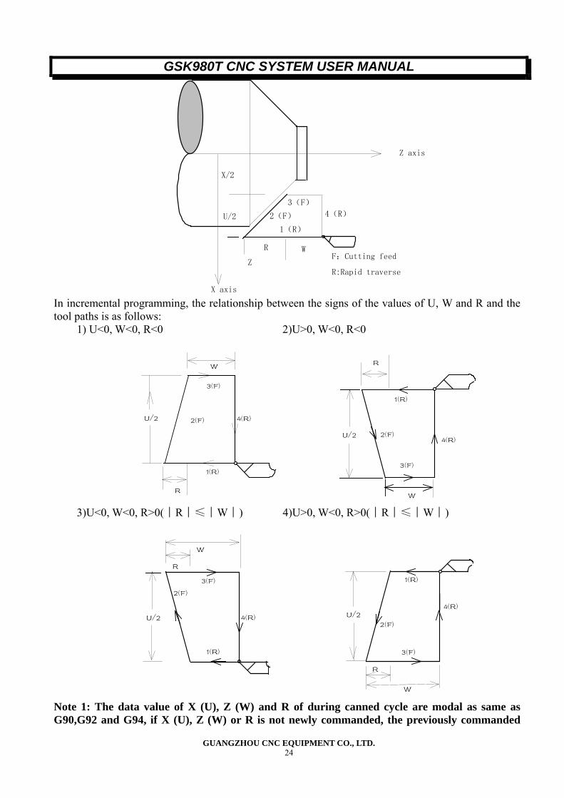
GSK980T CNC SYSTEM USER MANUAL
GUANGZHOU CNC EQUIPMENT CO., LTD. 24
X axis
Z axis
R:Rapid traverse
F:Cutting feed Z
X/2
U/2 4(R)
1(R)
2(F)
3(F)
WR
In incremental programming, the relationship between the signs of the values of U, W and R and the tool paths is as follows:
1) U<0, W<0, R<0 2)U>0, W<0, R<0
R
W
U/2
1(R)
2(F)
3(F)
4(R)
R
W
U/2
1(R)
2(F)
3(F)
4(R)
3)U<0, W<0, R>0(︱R︱≤︱W︱) 4)U>0, W<0, R>0(︱R︱≤︱W︱)
R
R
W
U/2
1(R)
2(F)
3(F)
4(R)
W
U/2
1(R)
2(F)
3(F)
4(R)
Note 1: The data value of X (U), Z (W) and R of during canned cycle are modal as same as G90,G92 and G94, if X (U), Z (W) or R is not newly commanded, the previously commanded
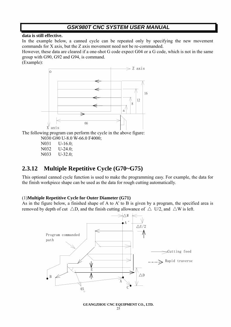
GSK980T CNC SYSTEM USER MANUAL
GUANGZHOU CNC EQUIPMENT CO., LTD. 25
data is still effective. In the example below, a canned cycle can be repeated only by specifying the new movement commands for X axis, but the Z axis movement need not be re-commanded. However, these data are cleared if a one-shot G code expect G04 or a G code, which is not in the same group with G90, G92 and G94, is command. (Example):
66
4
812
16
Z axis
X axis
O
The following program can perform the cycle in the above figure:
N030 G90 U-8.0 W-66.0 F4000; N031 U-16.0; N032 U-24.0; N033 U-32.0;
2.3.12 Multiple Repetitive Cycle (G70~G75) This optional canned cycle function is used to make the programming easy. For example, the data for the finish workpiece shape can be used as the data for rough cutting automatically.
(1)Multiple Repetitive Cycle for Outer Diameter (G71) As in the figure below, a finished shape of A to A’ to B is given by a program, the specified area is removed by depth of cut △D, and the finish cutting allowance of △ U/2, and △W is left.
A
Aˊ
B
C
△D
E
△U/2
△W
Program commanded
path
45
Rapid traverse
Cutting feed
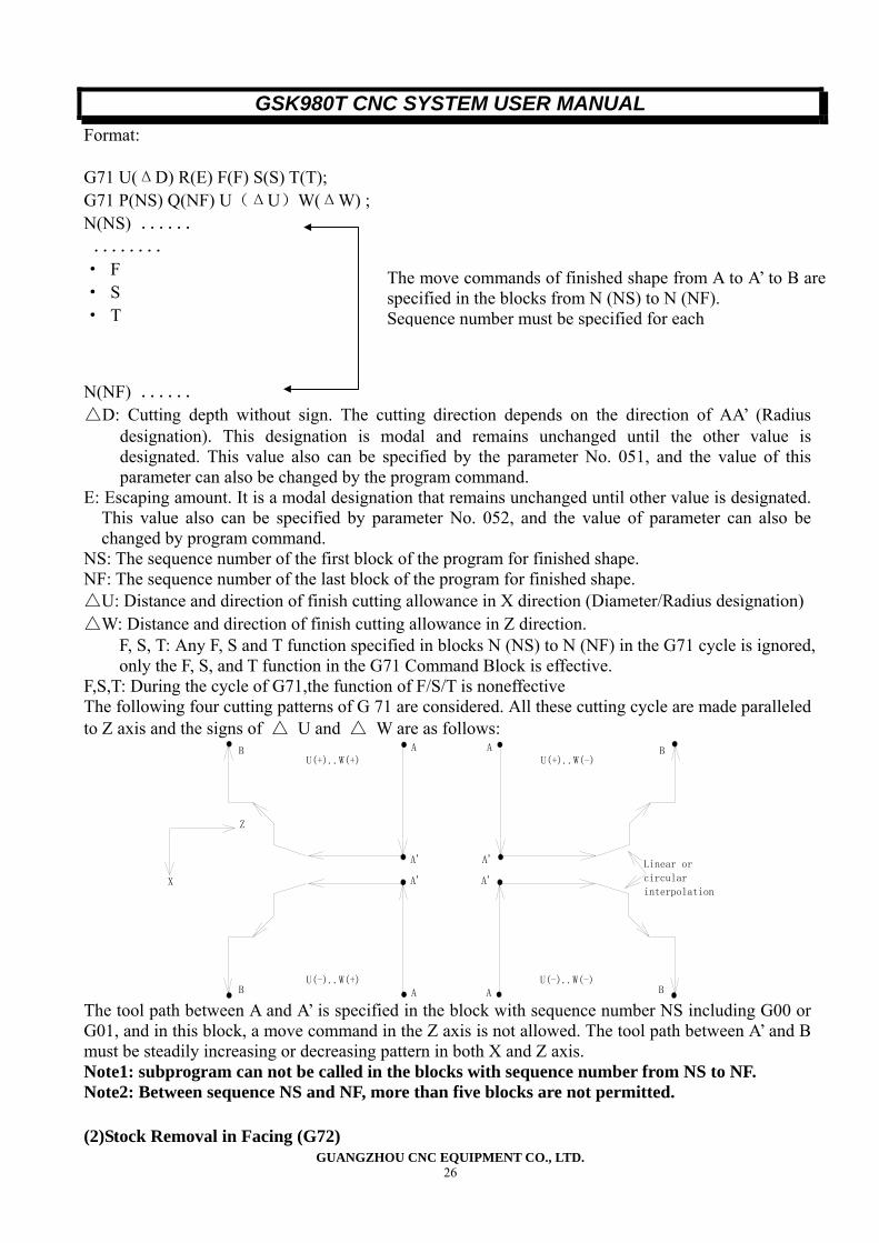
GSK980T CNC SYSTEM USER MANUAL
GUANGZHOU CNC EQUIPMENT CO., LTD. 26
Format: G71 U(ΔD) R(E) F(F) S(S) T(T); G71 P(NS) Q(NF) U(ΔU)W(ΔW) ; N(NS) ...... ........ · F · S · T N(NF) ...... △D: Cutting depth without sign. The cutting direction depends on the direction of AA’ (Radius
designation). This designation is modal and remains unchanged until the other value is designated. This value also can be specified by the parameter No. 051, and the value of this parameter can also be changed by the program command.
E: Escaping amount. It is a modal designation that remains unchanged until other value is designated. This value also can be specified by parameter No. 052, and the value of parameter can also be changed by program command.
NS: The sequence number of the first block of the program for finished shape. NF: The sequence number of the last block of the program for finished shape. △U: Distance and direction of finish cutting allowance in X direction (Diameter/Radius designation) △W: Distance and direction of finish cutting allowance in Z direction.
F, S, T: Any F, S and T function specified in blocks N (NS) to N (NF) in the G71 cycle is ignored, only the F, S, and T function in the G71 Command Block is effective.
F,S,T: During the cycle of G71,the function of F/S/T is noneffective The following four cutting patterns of G 71 are considered. All these cutting cycle are made paralleled to Z axis and the signs of △ U and △ W are as follows:
A
A'
B U(+)..W(+)
A
A'
B U(+)..W(-)
A
A'
B U(-)..W(+)
A
A'
B U(-)..W(-)
Z
X
Linear or
circular
interpolation
The tool path between A and A’ is specified in the block with sequence number NS including G00 or G01, and in this block, a move command in the Z axis is not allowed. The tool path between A’ and B must be steadily increasing or decreasing pattern in both X and Z axis. Note1: subprogram can not be called in the blocks with sequence number from NS to NF. Note2: Between sequence NS and NF, more than five blocks are not permitted. (2)Stock Removal in Facing (G72)
The move commands of finished shape from A to A’ to B arespecified in the blocks from N (NS) to N (NF). Sequence number must be specified for each
GSK980T CNC SYSTEM USER MANUAL
GUANGZHOU CNC EQUIPMENT CO., LTD. 27
As show in the figure below, this cycle is the same as G71 except that the cutting is made by an operation parallel to X axis.
△D
A
A'
B
C
E
△W
Program command
path
45
Rapid traverse
Cutting feed
△U/2
Tool path
G72 W (△D) R(E) F(F) S(S) T(T); G72 P(NS)Q(NF)U(△U)W(△W);
The means of △D, E, NS, △U, △W, F, S, T are the same as those in G71. Using G72, the following four cutting patterns are considered. All of these cutting cycles are made paralleled to X axis. The signs of △ U and △ W are as follows: The tool path between A and A’ is specified in the block with sequence number “NS” in which G00 or G01 can be included, but in and in this block, a move command in the X axis can not be specified. The tool path between A’ and B must be steadily increasing or decreasing pattern in both X and Z axis. Note1:The subprogram is not called in the block with the sequence number from NS to NF. Note2: Between sequence NS and NF, more than five blocks are not permitted.
U (-)..W (-).. R
U(+)..W(-)..
U (+)..W (+)..
U (-)..W (+).. X
RR
Z
A’A
Both linear and circular interpolation is possible
A’
A’ A A’ A
A
R
GSK980T CNC SYSTEM USER MANUAL
GUANGZHOU CNC EQUIPMENT CO., LTD. 28
(3)Pattern Repetitive Cutting Cycle (G73) Using cutting cycle permits cutting a fixed pattern repeatedly, with a pattern being displaced bit by bit. By this cutting cycle, it is possible to efficiently cut work whose rough shape has already been made by forging or casting method, etc.
A
A'
B
C
△U/2
△W
△U/2
△W
△K+△W
△u/2 △i+
D
The pattern commanded in the program should be as follows: A to A’ to B. G73 U(△I)W(△K)R(D) F(F) S(S) T(T); G73 P(NS)Q(NF)U(△U)W(△W);
N (NS)……… · · · · · · · · · · · · · ·
· N (NF) · · · ·
△ I: Distance and direction of relief in the X axis direction (Radius designation). This designation is modal and is not changed until the other value is designated. This value also can be specified by parameter No.053, and the parameter is changes by the program command. △K: Distance and direction of relief in the Z axis direction (Radius designation). This designation is modal and is not changed until the other value is designated. This value also can be specified by parameter No.054, and the parameter is changes by the program command. D: The number of division, which is the same as the repetitive count for rough cutting. This designation is modal and is not changed until the other value is designated. This value also can be set by parameter No.055, and the parameter is changed by the program command. NS: The sequence number of the last block of the program of finish shape. NF: The sequence number of the last block of the program of finish shape. △U: The finish cutting allowance in X direction (Diameter/Radius designation). △W: The finish cutting allowance in Z direction.
F, S, and T: Any F, S, and T function specified in the blocks between sequence number from NS to NF are non effective, but the F, S and T function is effective in the G73 block. Note1: △I, △K, or△U, △W is specified by address U and W respectively, the difference of them is determined by the address of P and Q.
The finish move command between A and B isspecified in the block from sequence number NS toNF
GSK980T CNC SYSTEM USER MANUAL
GUANGZHOU CNC EQUIPMENT CO., LTD. 29
Note 2:The cutting cycle is performed by G73 command with P and Q specification. The four cutting patterns are considered. Take care of the sign of △U, △W, △I, △K. When the cutting cycle is terminated, the tool returns to point A. Note3: Between sequence NS and NF, more than five blocks are not permitted. (4) Finish Cutting Cycle (G70) After rough cutting by G71, G72 and G73, the finish cutting can be performed by the following command:
G70 P (NS)Q(NF); NS: The sequence number of the first block of the program of finish shape. NF: The sequence number of the last block of the program of finish shape. Note 1: F, S and T specified in the block G71, G72 and G73 are noneffective for the G70 block .but F, S and T specified in the blocks between sequence number from Ns to NF for finish cutting are effective. Note 2: When the cutting specified by G70 is terminated, the tool returns to the start point and the next block is read. Note3: The subprogram can not be called in the blocks with sequence number from NS to NF between G70 and G73. Note4:Between sequence NS and NF, more than five blocks are not permitted. Example: ●Multiple repetitive cycle for outer diameter(G71):
b
100 60
30
40
0.2
80 20 30
Z axis
X axis
Start point
End point`
2 10
a
c
d e
10
(Diameter designation, metric input)
N010 G50 X200.0 Z220.0 ;(Workpiece coordinate system setting) N020 M3 S300;(Spindle CW rotation, spindle speed: 300 rpm) N030 M8;(Coolant on) N040 T0101;(Rough cutting tool) N050 G00 X160.0 Z180.0 ;(Positioning, come close to the workpiece) N060 G71 U4.0 R1.0 F300 S200;(Cutting depth 8mm[diameter designation] for each cut,1mm
relief)
GSK980T CNC SYSTEM USER MANUAL
GUANGZHOU CNC EQUIPMENT CO., LTD. 30
N070 G71 P080 Q120 U0.2 W2.0; N080 G00 X40.0 ; N090 G01 Z140.0 F100 S800 ;(The federate and spindle speed in finish cutting of G70) N100 X60.0 W-30.0 ; N110 W-20.0 ; N120 X100.0 W-10.0 ; N130 G00 X200.0 Z220.0 (Rapid traverse to a safe point) N140 T0202;(Tool No.2 and No.2 Offset) N150 G00 Z175.0(Positioning at rapid traverse speed) N160 G70 P80 Q120;(finish cutting a---d) N170 G00 X200.0 Z220.0 M05 S0; (Return to start point, stop the spindle) N180 M09;(Coolant off) N190 T0100;(Standard tool, cancel tool offset) N200 M30;(End of program) ●Multiple repetitive cycle(G70 G72)
201570
160
80
40
X
Z
7
88
Start poinp
110
190
220
a
b
c
d
O0002; N010 G50 X220.0 Z190.0 ; (Workpiece coordinate system setting) N015 T0202; (Exchange the tool No.2 and do No.2 tool-compensation) N017 M03 S200; (Spindle CW rotation and the speed is 200rpm)
( rough cutting a---d ,Finishing allowance in Xdirection 0.2mm, Z direction 2mm)
GSK980T CNC SYSTEM USER MANUAL
GUANGZHOU CNC EQUIPMENT CO., LTD. 31
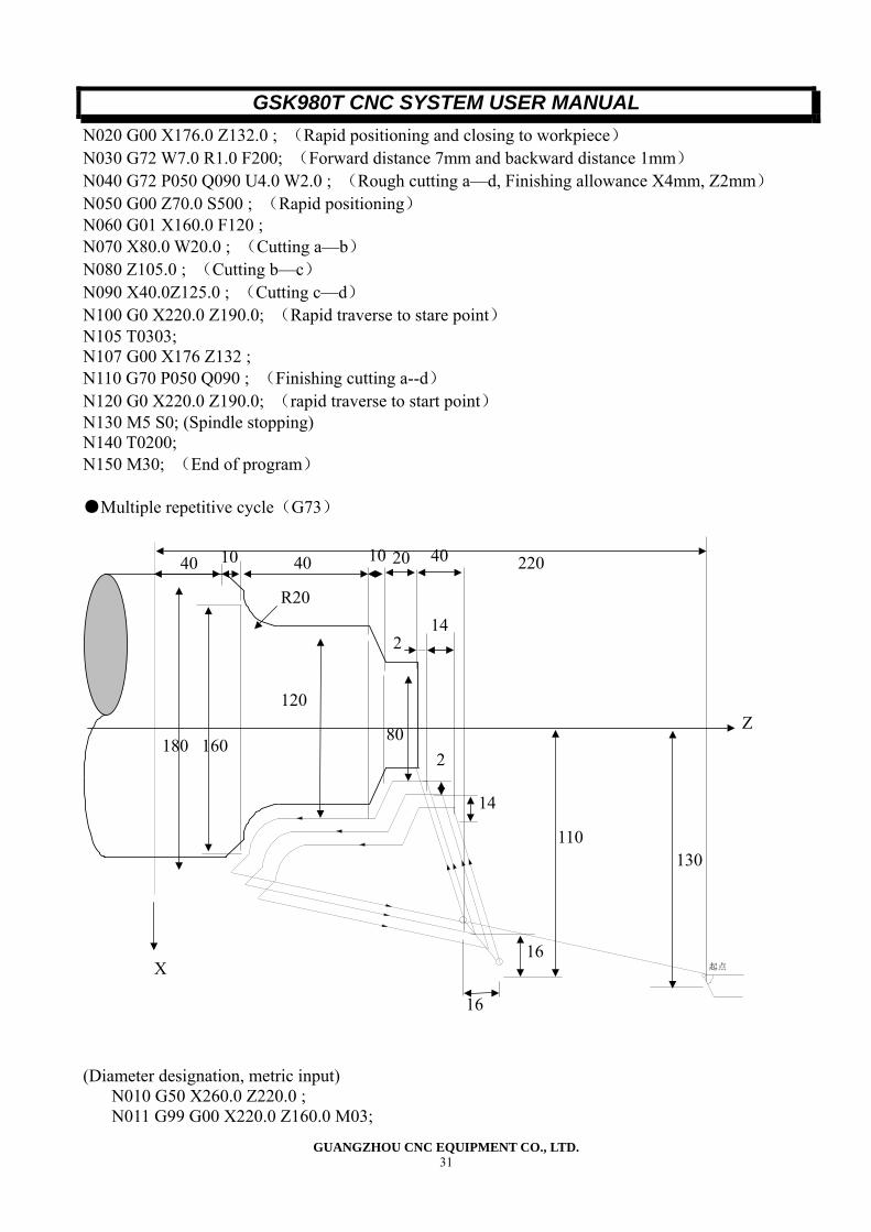
N020 G00 X176.0 Z132.0 ; (Rapid positioning and closing to workpiece) N030 G72 W7.0 R1.0 F200; (Forward distance 7mm and backward distance 1mm) N040 G72 P050 Q090 U4.0 W2.0 ; (Rough cutting a—d, Finishing allowance X4mm, Z2mm) N050 G00 Z70.0 S500 ; (Rapid positioning) N060 G01 X160.0 F120 ; N070 X80.0 W20.0 ; (Cutting a—b) N080 Z105.0 ; (Cutting b—c) N090 X40.0Z125.0 ; (Cutting c—d) N100 G0 X220.0 Z190.0; (Rapid traverse to stare point) N105 T0303; N107 G00 X176 Z132 ; N110 G70 P050 Q090 ; (Finishing cutting a--d) N120 G0 X220.0 Z190.0; (rapid traverse to start point) N130 M5 S0; (Spindle stopping) N140 T0200; N150 M30; (End of program) ●Multiple repetitive cycle(G73)
起点
(Diameter designation, metric input)
N010 G50 X260.0 Z220.0 ; N011 G99 G00 X220.0 Z160.0 M03;
16
2
80
10 40
R20
10 20 40 220
180 160
120
14
2
14
110130
Z
16X
40
GSK980T CNC SYSTEM USER MANUAL
GUANGZHOU CNC EQUIPMENT CO., LTD. 32
N012 G73 U14.0 W14.0 R0.003 F0.3 S280;(R0.003 means cycling 3 times) N013 G73 P014 Q018 U4.0 W2.0 ; N014 G00 X80.0 W-40.0 ; N015 G01 W-20.0 F0.15 S0600 ; N016 X120.0 W-10.0 ; N017 W-20.0 S0400 ; N018 G02 X160.0 W-20.0 R20.0 ; N019 G0 X250.0 Z200.0 ; N020 G70 P014 G018; N021 G0 X260.0 Z220.0; N022 M30;
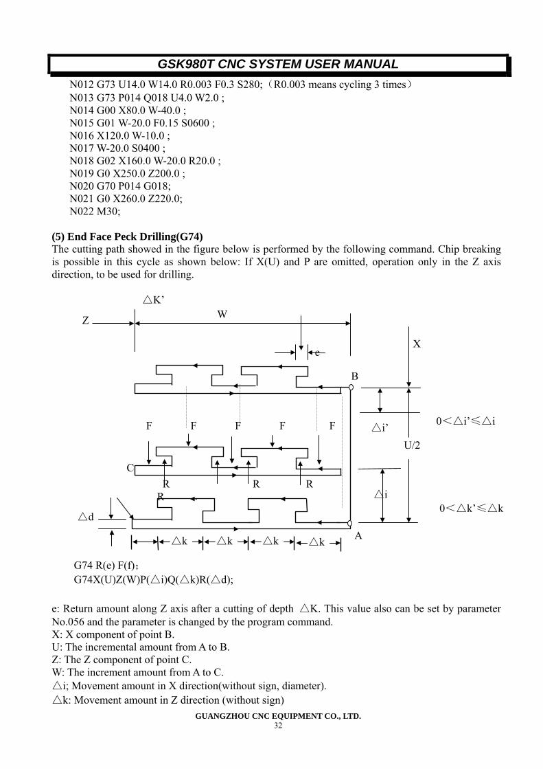
(5) End Face Peck Drilling(G74) The cutting path showed in the figure below is performed by the following command. Chip breaking is possible in this cycle as shown below: If X(U) and P are omitted, operation only in the Z axis direction, to be used for drilling.
G74 R(e) F(f); G74X(U)Z(W)P(△i)Q(△k)R(△d);
e: Return amount along Z axis after a cutting of depth △K. This value also can be set by parameter No.056 and the parameter is changed by the program command. X: X component of point B. U: The incremental amount from A to B. Z: The Z component of point C. W: The increment amount from A to C. △i; Movement amount in X direction(without sign, diameter). △k: Movement amount in Z direction (without sign)
e
C
W
△i
△i’
△d
△k△k△k△k
F F F F F
R R RR
Z
U/2
A
B
X
0<△k’≤△k
0<△i’≤△i
△K’
GSK980T CNC SYSTEM USER MANUAL
GUANGZHOU CNC EQUIPMENT CO., LTD. 33
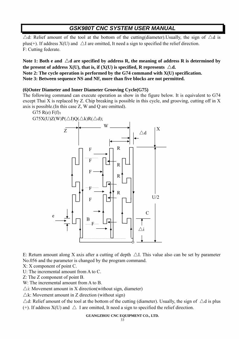
△d: Relief amount of the tool at the bottom of the cutting(diameter).Usually, the sign of △d is plus(+). If address X(U) and △I are omitted, It need a sign to specified the relief direction. F: Cutting federate. Note 1: Both e and △d are specified by address R, the meaning of address R is determined by the present of address X(U), that is, if (X(U) is specified, R represents △d. Note 2: The cycle operation is performed by the G74 command with X(U) specification. Note 3: Between sequence NS and NF, more than five blocks are not permitted. (6)Outer Diameter and Inner Diameter Grooving Cycle(G75) The following command can execute operation as show in the figure below. It is equivalent to G74 except Thai X is replaced by Z. Chip breaking is possible in this cycle, and grooving, cutting off in X axis is possible.(In this case Z, W and Q are omitted).
G75 R(e) F(f); G75X(U)Z(W)P(△I)Q(△k)R(△d);
E: Return amount along X axis after a cutting of depth △I. This value also can be set by parameter No.056 and the parameter is changed by the program command. X: X component of point C. U: The incremental amount from A to C. Z: The Z component of point B. W: The incremental amount from A to B. △i: Movement amount in X direction(without sign, diameter) △k: Movement amount in Z direction (without sign) △d: Relief amount of the tool at the bottom of the cutting (diameter). Usually, the sign of △d is plus (+). If address X(U) and △ I are omitted, It need a sign to specified the relief direction.
F F F F F
R
R
R R
XZ
△i
e
U/2
△d W
C
F B
GSK980T CNC SYSTEM USER MANUAL
GUANGZHOU CNC EQUIPMENT CO., LTD. 34
F: Cutting federate. Both G74 and G75 are used for grooving, cutting off and drilling. They can control the tool relief automatically. Note: Between sequence NS and NF, more than five blocks are not permitted.
2.3.13 Notes on Multiple Repetitive Cutting Cycle (G70~G75) (1). In the where the multiple repetitive cutting cycle is command, the address P, Q. X, Z, U, W, and R must be specified correctly for each block. (2). In the block which is specified by the address P in G71, G72 and G73 commands, G00 or G01 of 01 group must be commanded, if it is not commanded, alarm No.065 is generated. (3)G70,G71 and G72 can not be commanded in MDI mode. If on of them is commanded, alarm No.67 is generated. G74 and G75 can be command in MDI mode. (4) In the blocks in which G70,G71,G72 or G73 are commanded and in the blocks between the sequence number specified by address P and Q, M98/M99 can not be commanded. (5) in the blocks between the sequence number specified by address P and Q of G70, G71 G72, G73,the following commands can not be specified:
★ One shot G code except for G04 (Dwell) ★ 01 group G code except G00, G01 G02 and G03 ★ 06 group G code. ★ M98/M99
(6) While multiple repetitive cutting cycle(G70~G75) is being executed, it is permitted to stop the cycle operation to perform manual operation. But when the cycle operation is restart the tool should be returned to the position where the cycle operation is stop. It the cycle operation is added to the absolute value. And operation following is not correct, the tool path is shifted by the movement amount in manual operation. (7) When G70,G71,G72,and G73 is being executed, the sequence number specified by address P and Q should not be specified twice or more in the same program. (8) In G70,G71,G72and G73 cutting cycle, the last block of the finishing shape blocks group specified by address P and Q can not be chamfering or corner rounding, if is ,alarm No.69 is generated.
2.4 Spindle Function(S Function)
2.4.1 Spindle Speed Command By specified a numerical value following address S, to transmitted code signal to the machine tool for spindle speed control. Only one S code can be specified in one block. Refer to the appropriate operator manual issued by the machine tool builder for detail such as the number of digits of S code of how to use S code, etc… When a movement command and a S command is specified in the same block, they are executed at the sam4e time. (1) S 2-digit By specifying address S followed by 2-digit numerical value to control the speed of the spindle (Parameter No.001BIT-0). This system support 4 levels mechanical spindle speed gear change.(When the spindle analogue control in not available). Refer to the operation manual issued by the machine tool builder for the detail of the number of the levels of the spindle speed change and the relation between the S code and the spindle speed.
GSK980T CNC SYSTEM USER MANUAL
GUANGZHOU CNC EQUIPMENT CO., LTD. 35
S1~S4 The execution time of S code is set by diagnosis No.081. Setting value:0~255(128msec.~32.640msec.) Setting time=Setting value ×128 m sec. (2)S4-digit(Optional function) The spindle speed can be specified directly by address S followed by a 4-digit value (unit: rpm)(Parameter No.001BIT4=1), The unit for specifying the spindle speed may vary depending s the machine tool builder.
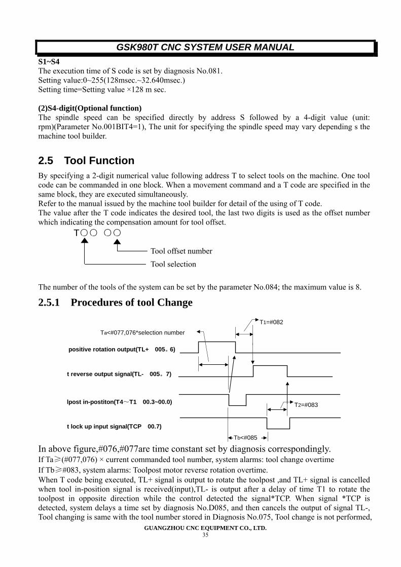
2.5 Tool Function By specifying a 2-digit numerical value following address T to select tools on the machine. One tool code can be commanded in one block. When a movement command and a T code are specified in the same block, they are executed simultaneously. Refer to the manual issued by the machine tool builder for detail of the using of T code. The value after the T code indicates the desired tool, the last two digits is used as the offset number which indicating the compensation amount for tool offset.
T○○ ○○ The number of the tools of the system can be set by the parameter No.084; the maximum value is 8.
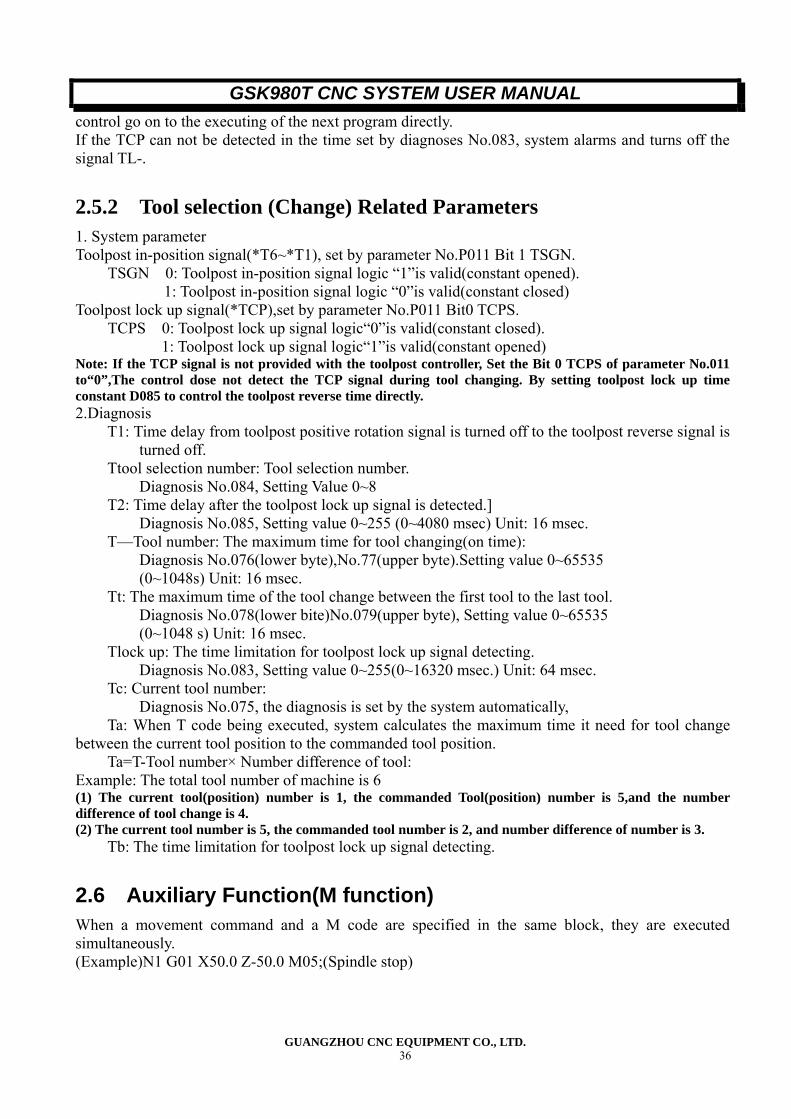
2.5.1 Procedures of tool Change
positive rotation output(TL+ 005。6)
t lock up input signal(TCP 00.7)
lpost in-postiton(T4~T1 00.3~00.0)
t reverse output signal(TL- 005。7)
T1=#082
T2=#083
Tb<#085
Ta<#077,076*selection number
In above figure,#076,#077are time constant set by diagnosis correspondingly. If Ta≥(#077,076) × current commanded tool number, system alarms: tool change overtime If Tb≥#083, system alarms: Toolpost motor reverse rotation overtime. When T code being executed, TL+ signal is output to rotate the toolpost ,and TL+ signal is cancelled when tool in-position signal is received(input),TL- is output after a delay of time T1 to rotate the toolpost in opposite direction while the control detected the signal*TCP. When signal *TCP is detected, system delays a time set by diagnosis No.D085, and then cancels the output of signal TL-, Tool changing is same with the tool number stored in Diagnosis No.075, Tool change is not performed,
Tool offset number Tool selection
GSK980T CNC SYSTEM USER MANUAL
GUANGZHOU CNC EQUIPMENT CO., LTD. 36
control go on to the executing of the next program directly. If the TCP can not be detected in the time set by diagnoses No.083, system alarms and turns off the signal TL-.
2.5.2 Tool selection (Change) Related Parameters 1. System parameter Toolpost in-position signal(*T6~*T1), set by parameter No.P011 Bit 1 TSGN.
TSGN 0: Toolpost in-position signal logic “1”is valid(constant opened). 1: Toolpost in-position signal logic “0”is valid(constant closed)
Toolpost lock up signal(*TCP),set by parameter No.P011 Bit0 TCPS. TCPS 0: Toolpost lock up signal logic“0”is valid(constant closed).
1: Toolpost lock up signal logic“1”is valid(constant opened) Note: If the TCP signal is not provided with the toolpost controller, Set the Bit 0 TCPS of parameter No.011 to“0”,The control dose not detect the TCP signal during tool changing. By setting toolpost lock up time constant D085 to control the toolpost reverse time directly. 2.Diagnosis
T1: Time delay from toolpost positive rotation signal is turned off to the toolpost reverse signal is turned off.
Ttool selection number: Tool selection number. Diagnosis No.084, Setting Value 0~8
T2: Time delay after the toolpost lock up signal is detected.] Diagnosis No.085, Setting value 0~255 (0~4080 msec) Unit: 16 msec.
T—Tool number: The maximum time for tool changing(on time): Diagnosis No.076(lower byte),No.77(upper byte).Setting value 0~65535 (0~1048s) Unit: 16 msec.
Tt: The maximum time of the tool change between the first tool to the last tool. Diagnosis No.078(lower bite)No.079(upper byte), Setting value 0~65535 (0~1048 s) Unit: 16 msec.
Tlock up: The time limitation for toolpost lock up signal detecting. Diagnosis No.083, Setting value 0~255(0~16320 msec.) Unit: 64 msec.
Tc: Current tool number: Diagnosis No.075, the diagnosis is set by the system automatically,
Ta: When T code being executed, system calculates the maximum time it need for tool change between the current tool position to the commanded tool position.
Ta=T-Tool number× Number difference of tool: Example: The total tool number of machine is 6 (1) The current tool(position) number is 1, the commanded Tool(position) number is 5,and the number difference of tool change is 4. (2) The current tool number is 5, the commanded tool number is 2, and number difference of number is 3.
Tb: The time limitation for toolpost lock up signal detecting.
2.6 Auxiliary Function(M function) When a movement command and a M code are specified in the same block, they are executed simultaneously. (Example)N1 G01 X50.0 Z-50.0 M05;(Spindle stop)
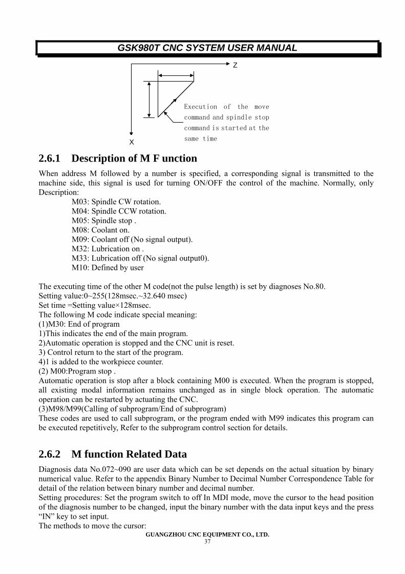
GSK980T CNC SYSTEM USER MANUAL
GUANGZHOU CNC EQUIPMENT CO., LTD. 37
Execution of the move
command and spindle stop
command is started at the
same time
Z
X 2.6.1 Description of M F unction When address M followed by a number is specified, a corresponding signal is transmitted to the machine side, this signal is used for turning ON/OFF the control of the machine. Normally, only Description:
M03: Spindle CW rotation. M04: Spindle CCW rotation. M05: Spindle stop . M08: Coolant on. M09: Coolant off (No signal output). M32: Lubrication on . M33: Lubrication off (No signal output0). M10: Defined by user
The executing time of the other M code(not the pulse length) is set by diagnoses No.80. Setting value:0~255(128msec.~32.640 msec) Set time =Setting value×128msec. The following M code indicate special meaning: (1)M30: End of program 1)This indicates the end of the main program. 2)Automatic operation is stopped and the CNC unit is reset. 3) Control return to the start of the program. 4)1 is added to the workpiece counter. (2) M00:Program stop . Automatic operation is stop after a block containing M00 is executed. When the program is stopped, all existing modal information remains unchanged as in single block operation. The automatic operation can be restarted by actuating the CNC. (3)M98/M99(Calling of subprogram/End of subprogram) These codes are used to call subprogram, or the program ended with M99 indicates this program can be executed repetitively, Refer to the subprogram control section for details.
2.6.2 M function Related Data Diagnosis data No.072~090 are user data which can be set depends on the actual situation by binary numerical value. Refer to the appendix Binary Number to Decimal Number Correspondence Table for detail of the relation between binary number and decimal number. Setting procedures: Set the program switch to off In MDI mode, move the cursor to the head position of the diagnosis number to be changed, input the binary number with the data input keys and the press “IN” key to set input. The methods to move the cursor:
GSK980T CNC SYSTEM USER MANUAL
GUANGZHOU CNC EQUIPMENT CO., LTD. 38
1)Use the pages change keys or the cursor move keys: 2)Use the searching function: P→The diagnoses number→IN No.076,077: The maximum time of tool change when the number difference of tool change is 1. (T---tool position)
Unit:16 msec. Setting range:0~65535 Setting value:[№077×256+№076]×16 msec Setting range: 0~1048.560 s
No.078, 079: The upper limit of the time for rating the toolpost from the first position to the last positions.
Unit: 16msec. Setting range:0~65535 Setting value:[№079×256+№078]×16 msec Setting range: 0~1048.560 s
No.080: The execution time of M code. Unit: 128 msec. Setting range:0~255 Setting value: (No.080+1)×128 msec Setting range: 128~32.768 s
No.081: The execution time of S code. Unit: 128 msec. Setting range:0~255 Setting value: (No.081+1)×128 msec Setting range: 128~32.768 s
No.082: Time change time T1 (The delay time required from the toolpost positive rotation signal end to the tool post reverse rotation signal issue).
Unit: 16 msec. Setting range:0~255 Setting value: (No.082+1)×16 msec Setting range: 16~4.096 s
No.083: The delay time for checking the *TCP signal(the upper limit time for the toolpost reverse rotation).
Unit: 64 msec. Setting range:0~255 Setting value: (№.083+1)×64 msec Setting range: 64~16.32 s
No.084: Maximum tool number selectable. Setting range:1~6
No.085: When signal*TCP is detected, system delays a time set by diagnosis No.D085, and then cancels the output of signal TL-, Tool changing is compete.
Unit:16 msec. Setting range:0~255 Setting value: (No.083+1)×16 msec Setting range:16~4.096 s
No.087,088: T2(Time from spindle command end to spindle brake issue) Unit:16 msec. Setting range:0~65535 Setting value: (No.088×256+No.087)×16 msec Setting range:0~1048.560 s
No.089,090: T3(Spindle brake signal output time).
GSK980T CNC SYSTEM USER MANUAL
GUANGZHOU CNC EQUIPMENT CO., LTD. 39
Unit:16 msec. Setting range:0~65535 Setting value: (No.090×256+No.089)×16 msec Setting range:0~1048.560 s
2.7 Program Configuration
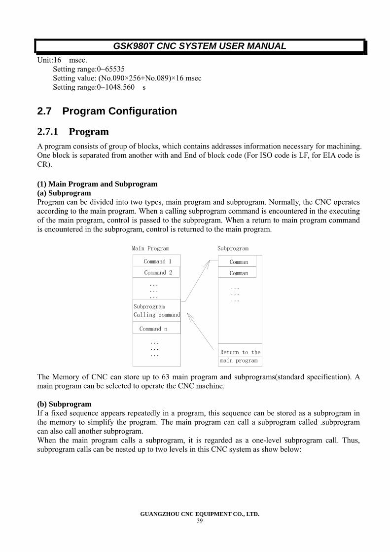
2.7.1 Program A program consists of group of blocks, which contains addresses information necessary for machining. One block is separated from another with and End of block code (For ISO code is LF, for EIA code is CR). (1) Main Program and Subprogram (a) Subprogram Program can be divided into two types, main program and subprogram. Normally, the CNC operates according to the main program. When a calling subprogram command is encountered in the executing of the main program, control is passed to the subprogram. When a return to main program command is encountered in the subprogram, control is returned to the main program.
Main Program Subprogram
Command 1
Command 2
Subprogram
Calling command
Command n
...
...
...
...
...
...
Comman
Comman
Return to the
main program
...
...
...
The Memory of CNC can store up to 63 main program and subprograms(standard specification). A main program can be selected to operate the CNC machine. (b) Subprogram If a fixed sequence appears repeatedly in a program, this sequence can be stored as a subprogram in the memory to simplify the program. The main program can call a subprogram called .subprogram can also call another subprogram. When the main program calls a subprogram, it is regarded as a one-level subprogram call. Thus, subprogram calls can be nested up to two levels in this CNC system as show below:
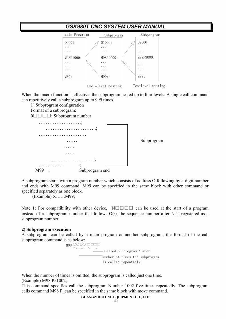
GSK980T CNC SYSTEM USER MANUAL
GUANGZHOU CNC EQUIPMENT CO., LTD. 40
O0001; ... ... ... M98P1000; ... ... ... ... M30;
Main Programm
O1000;.........M98P2000; ............M99;
Subprogram
O2000;.........M98P3000; ............M99;
Subprogram
One –level nesting Two-level nesting
When the macro function is effective, the subprogram nested up to four levels. A single call command can repetitively call a subprogram up to 999 times.
1) Subprogram configuration Format of a subprogram: 0□□□□; Subprogram number
……………………; ………………………..;
……………………… …… …… …… ……………………….;
………….. .; M99 ; Subprogram end
A subprogram starts with a program number which consists of address O following by a-digit number and ends with M99 command. M99 can be specified in the same block with other command or specified separately as one block.
(Example) X……M99; Note 1: For compatibility with other device, N□□□□ can be used at the start of a program instead of a subprogram number that follows O(:), the sequence number after N is registered as a subprogram number. 2) Subprogram execution A subprogram can be called by a main program or another subprogram, the format of the call subprogram command is as below:
M98
Number of times the subprogram
is called repeatedly
Called Subprogram Number
When the number of times is omitted, the subprogram is called just one time. (Example) M98 P51002; This command specifies call the subprogram Number 1002 five times repeatedly. The subprogram calls command M98 P_can be specified in the same block with move command.
Subprogram
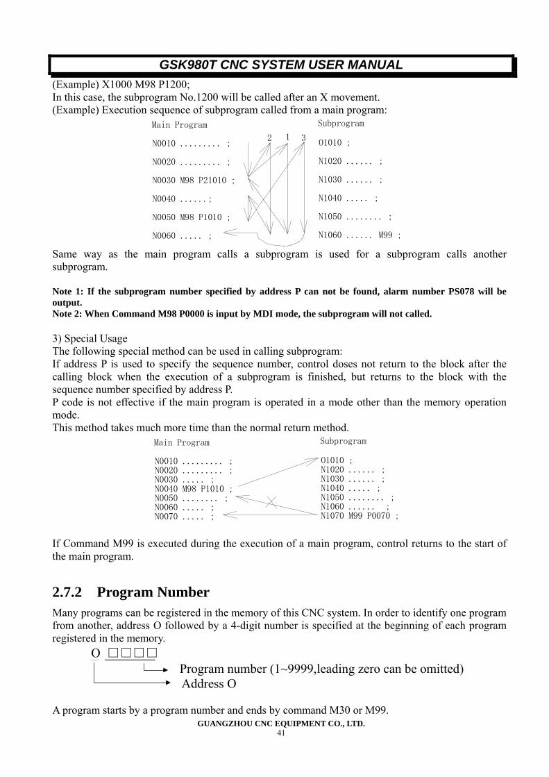
GSK980T CNC SYSTEM USER MANUAL
GUANGZHOU CNC EQUIPMENT CO., LTD. 41
(Example) X1000 M98 P1200; In this case, the subprogram No.1200 will be called after an X movement. (Example) Execution sequence of subprogram called from a main program:
N0010 ......... ; N0020 ......... ; N0030 M98 P21010 ; N0040 ......; N0050 M98 P1010 ; N0060 ..... ;
O1010 ;
N1020 ...... ;
N1030 ...... ;
N1040 ..... ;
N1050 ........ ;
N1060 ...... M99 ;
12 3
Main Program Subprogram
Same way as the main program calls a subprogram is used for a subprogram calls another subprogram. Note 1: If the subprogram number specified by address P can not be found, alarm number PS078 will be output. Note 2: When Command M98 P0000 is input by MDI mode, the subprogram will not called. 3) Special Usage The following special method can be used in calling subprogram: If address P is used to specify the sequence number, control doses not return to the block after the calling block when the execution of a subprogram is finished, but returns to the block with the sequence number specified by address P. P code is not effective if the main program is operated in a mode other than the memory operation mode. This method takes much more time than the normal return method.
N0010 ......... ; N0020 ......... ; N0030 ..... ; N0040 M98 P1010 ; N0050 ........ ; N0060 ..... ; N0070 ..... ;
O1010 ;N1020 ...... ; N1030 ...... ; N1040 ..... ; N1050 ........ ; N1060 ...... ; N1070 M99 P0070 ;
Main Program Subprogram
If Command M99 is executed during the execution of a main program, control returns to the start of the main program.
2.7.2 Program Number Many programs can be registered in the memory of this CNC system. In order to identify one program from another, address O followed by a 4-digit number is specified at the beginning of each program registered in the memory.
O □□□□ Program number (1~9999,leading zero can be omitted) Address O
A program starts by a program number and ends by command M30 or M99.
GSK980T CNC SYSTEM USER MANUAL
GUANGZHOU CNC EQUIPMENT CO., LTD. 42
2.7.3 Sequence Number and Block A program consists of several commands. One command unit is called a block. One block is separated from another with an End of block code. Notation “;”or “;” is used as an End of block code in this operation manual. At the head of a block, a sequence number consisting of address N followed by a number not longer than four digits can be specified. Sequence number may be specified in a random order and any numbers can be skipped. Sequence can be specified for all the block of a program or only for desired blocks of a program. For normal machining procedures, the sequence number should be arranged blocks in ascending order. It is convenient to specified sequence number for the blocks specifying important machining step (such as tool change or machining proceeds to a mew surface with table indexing). Note: Because 0 can not be as program number, 0 must not be used for a sequence number for the reason of compatibility with program number.
2.7.4 Word and Address Word is the basic of a block, a block consists of one or more words. A word consists of and address followed by a number (the plus sign (+) or minus sign (-)may be prefixed to a number).
X 1000
Address Number
Word
One of the letters A to Z can be used as an address. An address defines the meaning of a number that follows the address. The addresses and their meanings used in this system are as showed as the below table: Depending on the preparatory function, the same address may have deferent meanings. Function Address Meaning Program number O Program number Sequence number N Sequence number Preparatory function G Specified a movement mode (linear, arc etc )
X, Z, U, W Coordinate axis move command R Radius of arc Dimension words
I, K Coordinate of the center of arc Feedrate F Feedrate Spindle function S Spindle speed Tool function T Tool number Auxiliary function M ON/OFF control of the machine tool Dwell P, U, X Dwell time Program number P Subprogram number Number of repetitions P Number of subprogram repetition Parameter P, Q, R Specified the sequence number of the
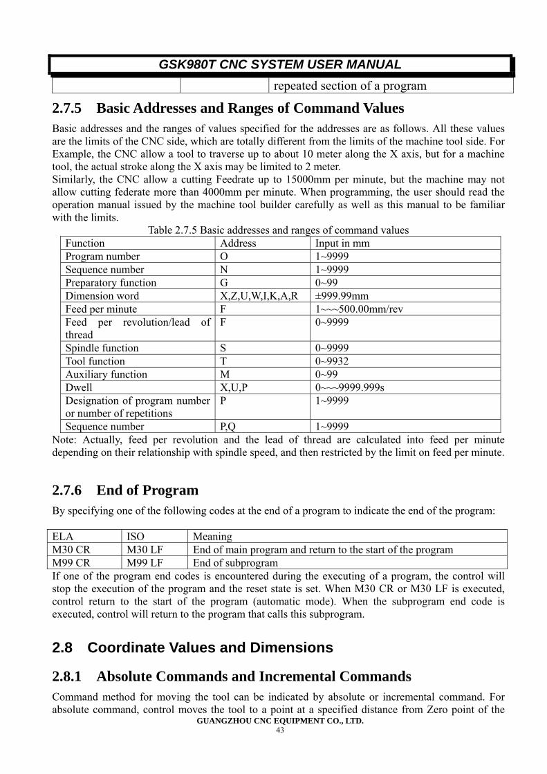
GSK980T CNC SYSTEM USER MANUAL
GUANGZHOU CNC EQUIPMENT CO., LTD. 43
repeated section of a program
2.7.5 Basic Addresses and Ranges of Command Values Basic addresses and the ranges of values specified for the addresses are as follows. All these values are the limits of the CNC side, which are totally different from the limits of the machine tool side. For Example, the CNC allow a tool to traverse up to about 10 meter along the X axis, but for a machine tool, the actual stroke along the X axis may be limited to 2 meter. Similarly, the CNC allow a cutting Feedrate up to 15000mm per minute, but the machine may not allow cutting federate more than 4000mm per minute. When programming, the user should read the operation manual issued by the machine tool builder carefully as well as this manual to be familiar with the limits.
Table 2.7.5 Basic addresses and ranges of command values Function Address Input in mm Program number O 1~9999 Sequence number N 1~9999 Preparatory function G 0~99 Dimension word X,Z,U,W,I,K,A,R ±999.99mm Feed per minute F 1~~~500.00mm/rev Feed per revolution/lead of thread
F 0~9999
Spindle function S 0~9999 Tool function T 0~9932 Auxiliary function M 0~99 Dwell X,U,P 0~~~9999.999s Designation of program number or number of repetitions
P 1~9999
Sequence number P,Q 1~9999 Note: Actually, feed per revolution and the lead of thread are calculated into feed per minute depending on their relationship with spindle speed, and then restricted by the limit on feed per minute. 2.7.6 End of Program By specifying one of the following codes at the end of a program to indicate the end of the program: ELA ISO Meaning M30 CR M30 LF End of main program and return to the start of the program M99 CR M99 LF End of subprogram If one of the program end codes is encountered during the executing of a program, the control will stop the execution of the program and the reset state is set. When M30 CR or M30 LF is executed, control return to the start of the program (automatic mode). When the subprogram end code is executed, control will return to the program that calls this subprogram.
2.8 Coordinate Values and Dimensions
2.8.1 Absolute Commands and Incremental Commands Command method for moving the tool can be indicated by absolute or incremental command. For absolute command, control moves the tool to a point at a specified distance from Zero point of the
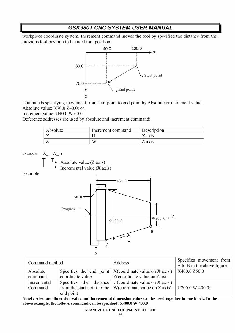
GSK980T CNC SYSTEM USER MANUAL
GUANGZHOU CNC EQUIPMENT CO., LTD. 44
workpiece coordinate system. Increment command moves the tool by specified the distance from the previous tool position to the next tool position.
100.040.0
70.0
30.0
Start point
End point
Z
X Commands specifying movement from start point to end point by Absolute or increment value: Absolute value: X70.0 Z40.0; or Increment value: U40.0 W-60.0; Deference addresses are used by absolute and increment command:
Absolute Increment command Description X U X axis Z W Z axis
Example: X_ W_ ;
Absolute value (Z axis) Incremental value (X axis) Example:
Φ400.0Φ200.0
450.0
50.0
Program
B
A
X
Z
Command method Address Specifies movement from
A to B in the above figure Absolute command
Specifies the end point coordinate value
X(coordinate value on X axis ) Z(coordinate value on Z axis
X400.0 Z50.0
Incremental Command
Specifies the distance from the start point to the end point
U(coordinate value on X axis ) W(coordinate value on Z axis) U200.0 W-400.0;
Note1: Absolute dimension value and incremental dimension value can be used together in one block. In the above example, the follows command can be specified: X400.0 W-400.0
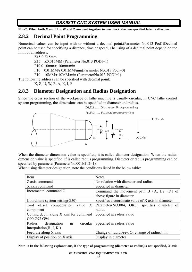
GSK980T CNC SYSTEM USER MANUAL
GUANGZHOU CNC EQUIPMENT CO., LTD. 45
Note2: When both X and U or W and Z are used together in one block, the one specified later is effective.
2.8.2 Decimal Point Programming Numerical values can be input with or without a decimal point.(Parameter No.013 Pod1)Decimal point can be used for specifying a distance, time or speed, The using of a decimal point depend on the limit of an address.
Z15.0 Z15mm Z15 Z0.015MM (Parameter No.013 PODI=1) F10.0 10mm/r, 10mm/min F10 0.01MM/r 0.01MM/min(Parameter No,013 Podi=0) F10 10MM/r 10MM/min (ParameterNo.013 PODI=1)
The following address can be specified with decimal point: X, Z, U, W, R, A, K, I, F
2.8.3 Diameter Designation and Radius Designation Since the cross section of the workpiece of lathe machine is usually circular, In CNC lathe control system programming, the dimensions can be specified in diameter and radius.
R2
D2D1R
A
B
Z axis
X axis
D1,D2 ..... Diameter Programming
R1,R2 ..... Radius programming
When the diameter dimension value is specified, it is called diameter designation. When the radius dimension value is specified, if is called radius programming. Diameter or radius programming can be specified by parameter(ParameterNo.001BIT2=1). When using diameter designation, note the conditions listed in the below table:
Item Notes Z axis command No relation with diameter and radius X axis command Specified in diameter Incremental command U Command the movement path B→A, D2→D1 of
above figure in diameter Coordinate system setting(G50) Specifies a coordinate value of X axis in diameter Tool offset compensation value X component
Parameter(NO.004, ORC) specifies diameter of radius
Cutting depth along X axis for command G90,G92 G94
Specified in radius value
Radius designation in circular interpolation(R, I, K )
Specified in radius value
Feedrate along X axis Change of radius/rev. Or change of radius/min Display of position on X axis Display in diameter
Note 1: In the following explanations, if the type of programming (diameter or radius)is not specified, X axis
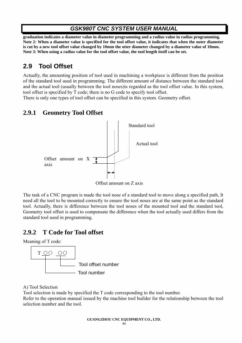
GSK980T CNC SYSTEM USER MANUAL
GUANGZHOU CNC EQUIPMENT CO., LTD. 46
graduation indicates a diameter value in diameter programming and a radius value in radius programming. Note 2: When a diameter value is specified for the tool offset value, it indicates that when the outer diameter is cut by a new tool offset value changed by 10mm the otter diameter changed by a diameter value of 10mm. Note 3: When using a radius value for the tool offset value, the tool length itself can be set.
2.9 Tool Offset Actually, the amounting position of tool used in machining a workpiece is different from the position of the standard tool used in programming. The different amount of distance between the standard tool and the actual tool (usually between the tool noses)is regarded as the tool offset value. In this system, tool offset is specified by T code; there is no G code to specify tool offset. There is only one types of tool offset can be specified in this system. Geometry offset.
2.9.1 Geometry Tool Offset
The task of a CNC program is made the tool nose of a standard tool to move along a specified path, It need all the tool to be mounted correctly to ensure the tool noses are at the same point as the standard tool. Actually, there is difference between the tool noses of the mounted tool and the standard tool, Geometry tool offset is used to compensate the difference when the tool actually used differs from the standard tool used in programming.
2.9.2 T Code for Tool offset Meaning of T code:
T ○○ ○○ A) Tool Selection Tool selection is made by specified the T code corresponding to the tool number. Refer to the operation manual issued by the machine tool builder for the relationship between the tool selection number and the tool.
Tool offset number
Tool number
Standard tool
Actual tool
Offset amount on Z axis
Offset amount on Xaxis
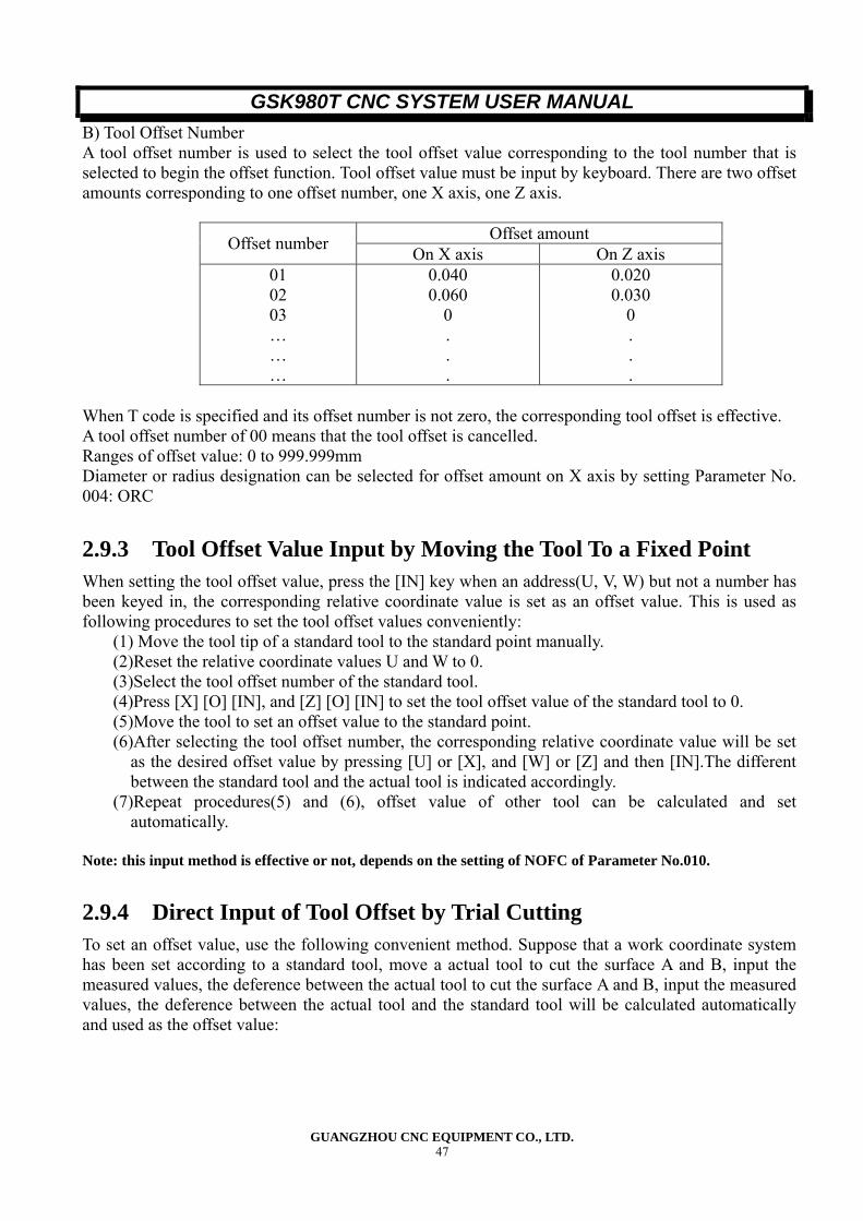
GSK980T CNC SYSTEM USER MANUAL
GUANGZHOU CNC EQUIPMENT CO., LTD. 47
B) Tool Offset Number A tool offset number is used to select the tool offset value corresponding to the tool number that is selected to begin the offset function. Tool offset value must be input by keyboard. There are two offset amounts corresponding to one offset number, one X axis, one Z axis.
Offset amount Offset number On X axis On Z axis 01 02 03 … … …
0.040 0.060
0 . . .
0.020 0.030
0 . . .
When T code is specified and its offset number is not zero, the corresponding tool offset is effective. A tool offset number of 00 means that the tool offset is cancelled. Ranges of offset value: 0 to 999.999mm Diameter or radius designation can be selected for offset amount on X axis by setting Parameter No. 004: ORC
2.9.3 Tool Offset Value Input by Moving the Tool To a Fixed Point When setting the tool offset value, press the [IN] key when an address(U, V, W) but not a number has been keyed in, the corresponding relative coordinate value is set as an offset value. This is used as following procedures to set the tool offset values conveniently:
(1) Move the tool tip of a standard tool to the standard point manually. (2)Reset the relative coordinate values U and W to 0. (3)Select the tool offset number of the standard tool. (4)Press [X] [O] [IN], and [Z] [O] [IN] to set the tool offset value of the standard tool to 0. (5)Move the tool to set an offset value to the standard point. (6)After selecting the tool offset number, the corresponding relative coordinate value will be set
as the desired offset value by pressing [U] or [X], and [W] or [Z] and then [IN].The different between the standard tool and the actual tool is indicated accordingly.
(7)Repeat procedures(5) and (6), offset value of other tool can be calculated and set automatically.
Note: this input method is effective or not, depends on the setting of NOFC of Parameter No.010.
2.9.4 Direct Input of Tool Offset by Trial Cutting To set an offset value, use the following convenient method. Suppose that a work coordinate system has been set according to a standard tool, move a actual tool to cut the surface A and B, input the measured values, the deference between the actual tool to cut the surface A and B, input the measured values, the deference between the actual tool and the standard tool will be calculated automatically and used as the offset value:
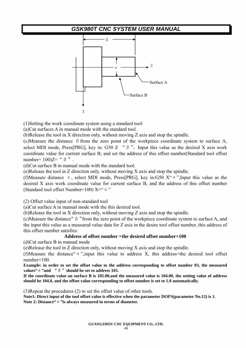
GSK980T CNC SYSTEM USER MANUAL
GUANGZHOU CNC EQUIPMENT CO., LTD. 48
Z
X
β
α
Surface A
Surface B
(1)Setting the work coordinate system using a standard tool: (a)Cut surfaces A in manual mode with the standard tool. (b)Release the tool in X direction only, without moving Z axis and stop the spindle. (c)Measure the distance βfrom the zero point of the workpiece coordinate system to surface A, select MDI mode, Press[PRG], key in: G50 Z “β”,Input this value as the desired X axis work coordinate value for current surface B, and set the address of this offset number(Standard tool offset number+ 100)Z=“β”. (d)Cut surface B in manual mode with the standard tool. (e)Release the tool in Z direction only, without moving X axis and stop the spindle. (f)Measure distance α, select MDI mode, Press[PRG], key in:G50 X“α”,Input this value as the desired X axis work coordinate value for current surface B, and the address of this offset number (Standard tool offset Number=100) X=“α” (2) Offset value input of non-standard tool (a)Cut surface A in manual mode with the this desired tool. (b)Release the tool in X direction only, without moving Z axis and stop the spindle. (c)Measure the distance“β”from the zero point of the workpiece coordinate system to surface A, and the input this value as a measured value data for Z axis in the desire tool offset number, this address of this offset number satisfies:
Address of offset number =the desired offset number+100 (d)Cut surface B in manual mode (e)Release the tool in Z direction only, without moving X axis and stop the spindle. (f)Measure the distance“α”,input this value to address X, this address=the desired tool offset number+100. Example: in order to set the offset value to the address corresponding to offset number 03, the measured values“α”and “β”should be set to address 103. If the coordinate value on surface B is 105.00,and the measured value is 104.00, the setting value of address should be 104.0, and the offset value corresponding to offset number is set to 1.0 automatically. (3)Repeat the procedures (2) to set the offset value of other tools. Note1: Direct input of the tool offset value is effective when the parameter DOFS(parameter No.12) is 1. Note 2: Distance“α”is always measured in terms of diameter.
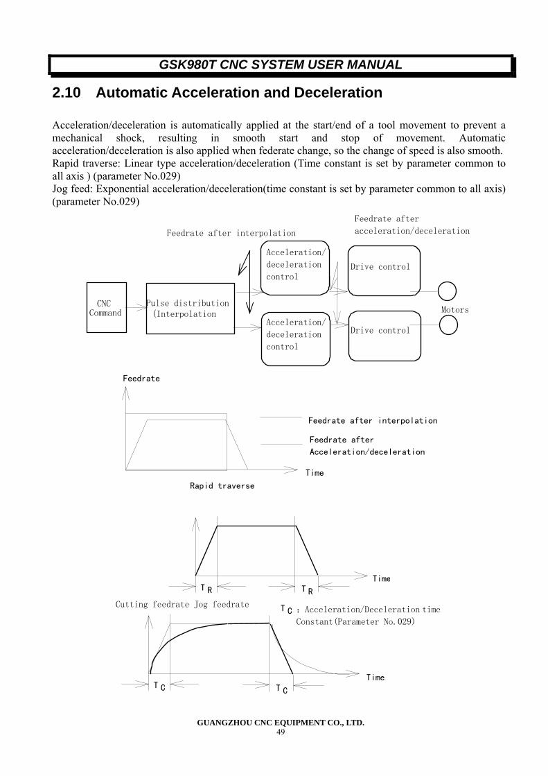
GSK980T CNC SYSTEM USER MANUAL
GUANGZHOU CNC EQUIPMENT CO., LTD. 49
2.10 Automatic Acceleration and Deceleration
Acceleration/deceleration is automatically applied at the start/end of a tool movement to prevent a mechanical shock, resulting in smooth start and stop of movement. Automatic acceleration/deceleration is also applied when federate change, so the change of speed is also smooth. Rapid traverse: Linear type acceleration/deceleration (Time constant is set by parameter common to all axis ) (parameter No.029) Jog feed: Exponential acceleration/deceleration(time constant is set by parameter common to all axis) (parameter No.029)
CNC Command
Pulse distribution(Interpolation
Acceleration/
deceleration
control
Acceleration/
deceleration
control
Drive control
Drive control
Feedrate after interpolation
Feedrate after
acceleration/deceleration
Motors
Feedrate after interpolation
Feedrate after
Acceleration/deceleration
Time
Feedrate
Time
Rapid traverse
T RT R
T CTime
T C
Cutting feedrate Jog feedrate T C :Acceleration/Deceleration time
Constant(Parameter No.029)
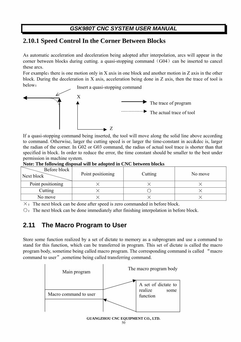
GSK980T CNC SYSTEM USER MANUAL
GUANGZHOU CNC EQUIPMENT CO., LTD. 50
X
2.10.1 Speed Control In the Corner Between Blocks
As automatic acceleration and deceleration being adopted after interpolation, arcs will appear in the corner between blocks during cutting. a quasi-stopping command(G04)can be inserted to cancel these arcs. For example:there is one motion only in X axis in one block and another motion in Z axis in the other block. During the deceleration in X axis, acceleration being done in Z axis, then the trace of tool is below: If a quasi-stopping command being inserted, the tool will move along the solid line above according to command. Otherwise, larger the cutting speed is or larger the time-constant in acc&dec is, larger the radian of the corner. In G02 or G03 command, the radius of actual tool trace is shorter than that specified in block. In order to reduce the error, the time constant should be smaller to the best under permission in machine system. Note: The following disposal will be adopted in CNC between blocks
Point positioning Cutting No move
Point positioning × × × Cutting × ○ ×
No move × × × ×:The next block can be done after speed is zero commanded in before block. ○:The next block can be done immediately after finishing interpolation in before block.
2.11 The Macro Program to User
Store some function realized by a set of dictate to memory as a subprogram and use a command to stand for this function, which can be transferred in program. This set of dictate is called the macro program body, sometime being called macro program. The corresponding command is called “macro command to user”,sometime being called transferring command.
Insert a quasi-stopping command
Z
The trace of program
The actual trace of tool
Next block Before block
Main program
Macro command to user
A set of dictate torealize somefunction
The macro program body
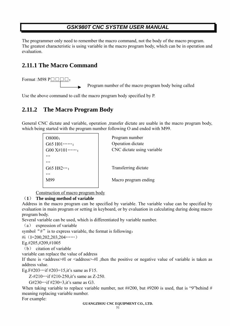
GSK980T CNC SYSTEM USER MANUAL
GUANGZHOU CNC EQUIPMENT CO., LTD. 51
The programmer only need to remember the macro command, not the body of the macro program. The greatest characteristic is using variable in the macro program body, which can be in operation and evaluation.
2.11.1 The Macro Command
Format :M98 P□□□□; Use the above command to call the macro program body specified by P.
2.11.2 The Macro Program Body
General CNC dictate and variable, operation ,transfer dictate are usable in the macro program body, which being started with the program number following O and ended with M99.
Construction of macro program body (1) The using method of variable Address in the macro program can be specified by variable. The variable value can be specified by evaluation in main program or setting in keyboard, or by evaluation in calculating during doing macro program body. Several variable can be used, which is differentiated by variable number. (a) expression of variable symbol“#”is to express variable, the format is following: #i(I=200,202,203,204……) Eg.#205,#209,#1005 (b) citation of variable variable can replace the value of address If there is <address>#I or <address>-#I ,then the positive or negative value of variable is taken as address value. Eg.F#203…if #203=15,it’s same as F15. Z-#210…if #210-250,it’s same as Z-250. G#230…if #230=3,it’s same as G3. When taking variable to replace variable number, not ##200, but #9200 is used, that is “9”behind # meaning replacing variable number. For example:
Program number of the macro program body being called
O8000; G65 H01……; G00 X#101……; … … G65 H82…; … M99
Program number Operation dictate CNC dictate using variable
Transferring dictate
Macro program ending
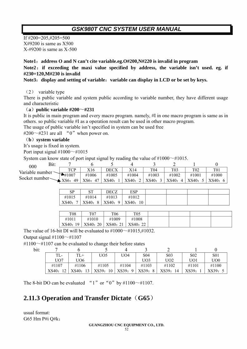
GSK980T CNC SYSTEM USER MANUAL
GUANGZHOU CNC EQUIPMENT CO., LTD. 52
000 Variable number Socket number
If #200=205,#205=500 X#9200 is same as X500 X-#9200 is same as X-500 Note1:address O and N can’t cite variable.eg.O#200,N#220 is invalid in program Note2: if exceeding the maxi value specified by address, the variable isn’t used. eg. if #230=120,M#230 is invalid Note3:display and setting of variable:variable can display in LCD or be set by keys. (2) variable type There is public variable and system public according to variable number, they have different usage and characteristic (a)public variable #200~#231 It is public in main program and every macro program. namely, #I in one macro program is same as in others. so public variable #I as a operation result can be used in other macro program. The usage of public variable isn’t specified in system can be used free #200~#231 are all “0”when power on. (b)system variable It’s usage is fixed in system. Port input signal #1000~#1015 System can know state of port input signal by reading the value of #1000~#1015. Bit: 7 6 5 4 3 2 1 0
TCP X16 DECX X14 T04 T03 T02 T01 #1007
XS6:49 #1006
XS6:47 #1005
XS40:1#1004
XS40:2#1003
XS40:3#1002
XS40:4 #1001
XS40:5 #1000
XS40:6
SP ST DECZ ESP #1015
XS40:7 #1014
XS40:8 #1013
XS40:9#1012
XS40:10
T08 T07 T06 T05
#1011 XS40:19
#1010 XS40:20
#1009 XS40:21
#1008 XS40:22
The value of 16-bit DI will be evaluated to #1000~#1015,#1032. Output signal #1100~#1107 #1100~#1107 can be evaluated to change their before states
bit: 7 6 5 4 3 2 1 0 TL- UO7
TL+ UO6
UO5 UO4 S04 UO3
S03 UO2
S02 UO1
S01 UO0
#1107 XS40:12
#1106 XS40:13
#1105 XS39:10
#1104 XS39:9
#1103 XS39:8
#1102 XS39:14
#1101 XS39:1
#1100 XS39:5
The 8-bit DO can be evaluated “1”or“0”by #1100~#1107.
2.11.3 Operation and Transfer Dictate(G65)
usual format: G65 Hm P#i Q#k;
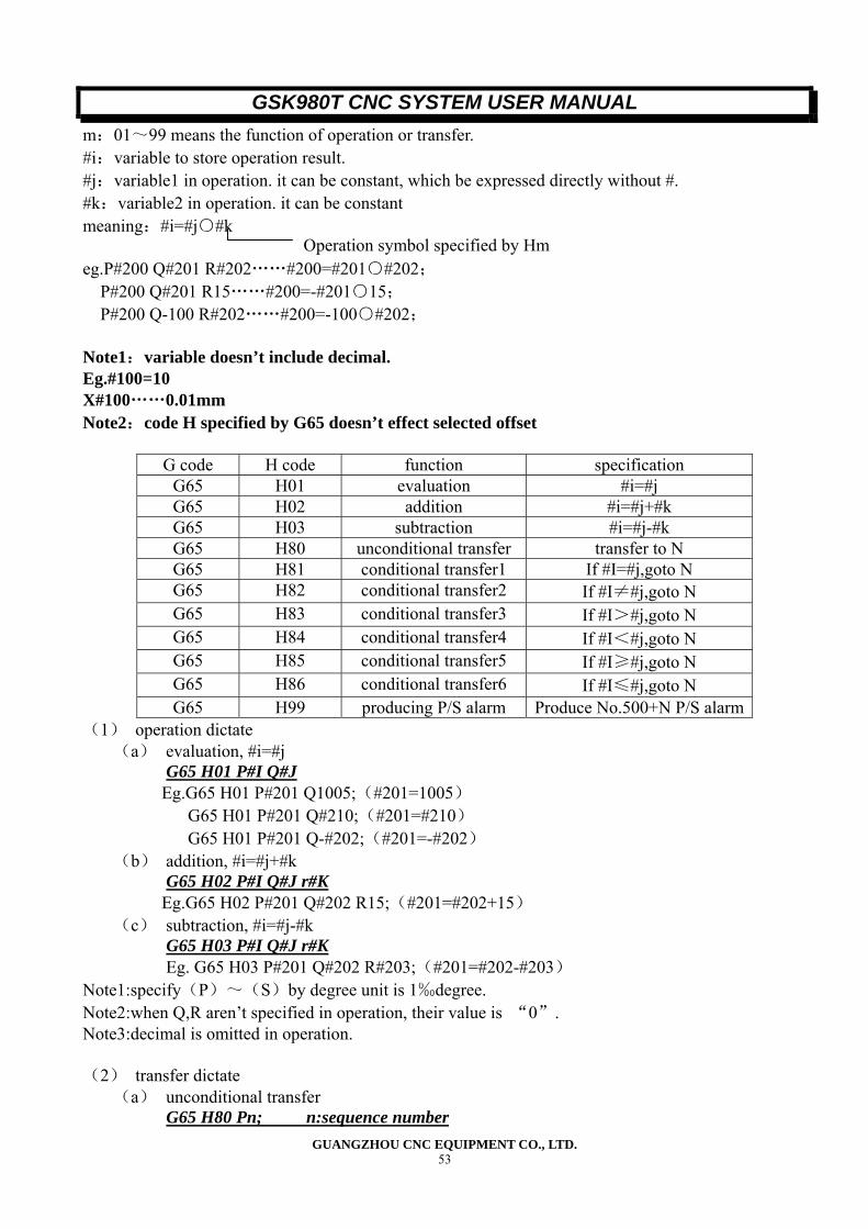
GSK980T CNC SYSTEM USER MANUAL
GUANGZHOU CNC EQUIPMENT CO., LTD. 53
m:01~99 means the function of operation or transfer. #i:variable to store operation result. #j:variable1 in operation. it can be constant, which be expressed directly without #. #k:variable2 in operation. it can be constant meaning:#i=#j○#k eg.P#200 Q#201 R#202……#200=#201○#202; P#200 Q#201 R15……#200=-#201○15; P#200 Q-100 R#202……#200=-100○#202; Note1:variable doesn’t include decimal. Eg.#100=10 X#100……0.01mm Note2:code H specified by G65 doesn’t effect selected offset
G code H code function specification G65 H01 evaluation #i=#j G65 H02 addition #i=#j+#k G65 H03 subtraction #i=#j-#k G65 H80 unconditional transfer transfer to N G65 H81 conditional transfer1 If #I=#j,goto N G65 H82 conditional transfer2 If #I≠#j,goto N G65 H83 conditional transfer3 If #I>#j,goto N G65 H84 conditional transfer4 If #I<#j,goto N G65 H85 conditional transfer5 If #I≥#j,goto N G65 H86 conditional transfer6 If #I≤#j,goto N G65 H99 producing P/S alarm Produce No.500+N P/S alarm
(1) operation dictate (a) evaluation, #i=#j
G65 H01 P#I Q#J Eg.G65 H01 P#201 Q1005;(#201=1005)
G65 H01 P#201 Q#210;(#201=#210) G65 H01 P#201 Q-#202;(#201=-#202)
(b) addition, #i=#j+#k G65 H02 P#I Q#J r#K
Eg.G65 H02 P#201 Q#202 R15;(#201=#202+15) (c) subtraction, #i=#j-#k
G65 H03 P#I Q#J r#K Eg. G65 H03 P#201 Q#202 R#203;(#201=#202-#203)
Note1:specify(P)~(S)by degree unit is 1‰degree. Note2:when Q,R aren’t specified in operation, their value is “0”. Note3:decimal is omitted in operation. (2) transfer dictate
(a) unconditional transfer G65 H80 Pn; n:sequence number
Operation symbol specified by Hm
GSK980T CNC SYSTEM USER MANUAL
GUANGZHOU CNC EQUIPMENT CO., LTD. 54
Eg.G65 H80 P120; (transfer to N120 block) (b) conditional transfer1 #j.EQ.#k(=)
G65 H81 Pn Q#J R#K; n:sequence number Eg.G65 H81 P1000 Q#201 R#202; When #201=#202,transfer to N1000 block, when #201≠#202,run sequently.
(c) conditional transfer2 #j.NE.#k(≠) G65 H82 Pn Q#J R#K; n:sequence number Eg.G65 H82 P1000 Q#201 R#202; When #201≠#202,transfer to N1000 block, when #201=#202,run sequently.
(d) conditional transfer3 #j.GT.#k(>) G65 H83 Pn Q#J R#K; n:sequence number Eg.G65 H83 P1000 Q#201 R#202; When #201>#202,transfer to N1000 block,when #201≤#202,run sequently.
(e) conditional transfer4 #j.LT.#k(<) G65 H84 Pn Q#J R#K; n:sequence number Eg.G65 H84 P1000 Q#201 R#202; When #201<#202,transfer to N1000 block,when #201≥#202,run sequently.
(f) conditional transfer5 #j.GE.#k(≥) G65 H85 Pn Q#J R#K; n:sequence number Eg.G65 H85 P1000 Q#201 R#202; When #201≥#202,transfer to N1000 block,when #201<#202,run sequently.
(g) conditional transfer6 #j.LE.#k(≤) G65 H86 Pn Q#J R#K; n:sequence number Eg.G65 H86 P1000 Q#201 R#202; When #201≤#202,transfer to N1000 block,when #201>#202,run sequently.
(h) produce P/S alarm G65 H99 Pi; i:alarm number+500 Eg.G65 H99 P15; Produce P/S alarm No.515.
Note1:when the transfer address is positive, searching direction is sequent first ,then restrorse. when negative, searching direction is retrorse first ,then sequent. Note2:sequence number can be specified by variable also.
G65 H81 P#200 Q#201 R#202 When condition is satisfied, transfer to the block specified by #200
2.11.4 The Note about the Macro Program Body
(1) the method of using key press # after G,X,Z,U,W,R,I,K,F,H,M,S,T,P,Q to input # (2) operation and transfer dictate can be commanded in MDI mode expect G65,other address only can be input, not be displayed. (3) H,P,Q, R must be written behind G65 in operation and transfer, only O and N can be written before G65. H02 G65 P#200 Q#201 R#202; error N100 G65 H01 P#201 Q10; right (4) single block usually, program doesn’t stop in doing operation or transfer when program switch is ON. but, single
GSK980T CNC SYSTEM USER MANUAL
GUANGZHOU CNC EQUIPMENT CO., LTD. 55
block can stop according to parameter(No.013 SBKM),which is used in debugging. (5) variable range is -232~+232-1,while right display range is -9999999~+9999999,******* will displayed when exceeding this range. (6) subprogram nesting is 4 layers (7) variable only is integer, decimal in operation result will be omitted. (8) Doing time of operation and transfer is different conditionally. the average time is 10ms.
2.11.5 Example for User
eg. user dictate M61(feed automatically) main program O0001: N10 G50 X100 Z100;(define coordinate system) N20 G00 U50 F100;(fast traverse) N30 G01 U0.8;(feed) N40 M61;(call subprogram No.O9061) N50 G0 X100 Z100;(finish feed and clear point) N60 M99;(repeat doing) subprogram(M61) O9061: N10 G65 H01 P#1104 Q1;(U04=1 output feed signal)
G65 H82 P20 Q#1004 R1;(if X14=1,sequently do.if X14=0,do N20 block) G65 H01 P#1100 Q0;(cancel feed signal,U04=0) M99 P50;(transfer N50 block)
N20 M99 P30;(transfer N30 block)
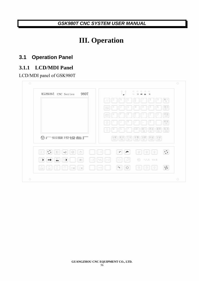
GSK980T CNC SYSTEM USER MANUAL
GUANGZHOU CNC EQUIPMENT CO., LTD. 56
III. Operation
3.1 Operation Panel
3.1.1 LCD/MDI Panel LCD/MDI panel of GSK980T
980T MST
GSK980T CNC SYSTEM USER MANUAL
GUANGZHOU CNC EQUIPMENT CO., LTD. 57
3.1.2 Screen Change Keys Screen change keys are used to switch display screen, For GSK980T, there are seven types of display screen can be selected: Position, Program, and Tool offset, Alarm, Setting, Parameter and Diagnosis. Explanation of screens: [POS]:Current position display, there are total four pages corresponding to absolute coordinate display, relative coordinate display, Overall, Position/program. They can be selected by page change keys. [PRG];Program display and edit, there are total three pages: MDI/MODAL, PRG, Content/Program memory used. [OFT]:Display and setting compensation data and micro variable including:[Offset],[Macro variable]. [PAR]:Parameter display and setting. [DGN]:Display of diagnosis data. [ALM]:Display of alarm messages. [SET]:Display and setting parameter, parameter ON/OFF and Program ON/OFF.
3.1.3 Explanation of Key Board Number Name Description 1 Reset Key(∥) Reset CNC and cancel alarm 2 Output key(OUT) Starts the file output from RS232 interface 3 Address/numeric keys Input letter, numeric, and other characters
4 Input key(IN) Confirm the input of parameter, offset value, etc, Start
the input of file from RS232 interface; confirm the input of command from MDI mode.
5
Cancel (CAN) Cancel the character of symbol input to the key input buffer. Then content of the key input buffer is displayed by the LCD screen. For example: when the key input buffer is displayed as: N001 And the cancel key(CAN)is pressed, N0001 is canceled.
6
Cursor move keys There are four kings cursor move keys: ↓: moves the cursor in a downward direction. ↓: Depress the cursor move key, the cursor moves continuously W\L: Used to set the ON/OFF of the parameter switch and the display bit of the bit parameter and bit diagnosis.
7
Page change keys There are two kinds of page change keys: ↓: Changeover the page on the LCD screen in the forward direction; ↓: Changeover the page on the LCD screen in the reverse direction.
8 Edit keys(INS, DEL, ALT) For editing program including Insertion, deletion and amend.
9 CHC key Display mode change key for the meaning of Bit parameter and bit diagnosis.
GSK980T CNC SYSTEM USER MANUAL
GUANGZHOU CNC EQUIPMENT CO., LTD. 58
3.1.4 Machine Operation Panel Buttons and switches on the operation panel are listed at the below table: Description of button and switches
Name Function
Cycle start button Start the automatic operation cycle. The indicator indicating automatic operation is on during the automatic operation.
Feed hold button The tool decelerates and the stops. Mode select button Select operation mode Rapid traverse button By pressing this button, the tool is fed rapidly. Feed direction select push button
Select the movement direction for manual continuous feed and step feed.
Start point return button When this switch is in the ON positron, start point return mode is selected.
Rapid traverse override Select the amount of rapid traverse override. Step/handle feed amount During step mode, select the moving amount per step. Emergency stop . By pressing this button, the machine is stop emergently Machine lock Machine lock. Feedrate override Select the amount of override for automatic operation Manual continuous federate Select the feed rate of manual continuous feed. Handle feed axis selection Select the axis moved by the manual handle
Step/handle feed amount During manual handle feed, select the multiplier of the moving amount per step.
Spindle start Manual spindle forward rotation, reverse rotation, spindle jog, spindle stop
Spindle override Spindle override selecting(analogue spindle speed control signal)
Coolant on Coolant pump start (refer to the operation manual issued by machine tool builder for detail)
Lubrication on Lubrication on (refer to the operation manual issued by machine tool builder for detail)
Manual tool change Manual change of tools (refer to the Operation Manual issued by machine tool builder for detail
GSK980T CNC SYSTEM USER MANUAL
GUANGZHOU CNC EQUIPMENT CO., LTD. 59
3.2 Manual Operation
3.2.1 Manual Reference Point Return (1) Push the Reference point return key to select the reference point return operation mode. “Mach ZRN” will be displayed at the right bottom of the LCD screen. (2) Depress the feed direction key until the reference point of the selected axis is reached.
The tool moves along the selected axis to the decelerated point at the rapid traverse rate, the moves to the reference point at the speed FL(Parameter No.032). A rapid traverse override is effective during rapid traverse motion. FL speed is set by parameter No.032.(When reference point return mode Bis selected) (3) When the reference point is reached, the reference point return completion LED lights.
Reference point return completion LED
3.2.2 Manual start Point Return (1)Push the start point return key to select the start point return operation mode,[程序回零]
will be displayed at the right bottom of the LCD screen. (2)Select the axis. The tool moves along the selected axis to the start point and stops, then the address of the
position[X], [Z], [U], [W] is flickering. After the start point return is complete, the tool-offset compensation will be canceled automatically.
Start point return completion LED
GSK980T CNC SYSTEM USER MANUAL
GUANGZHOU CNC EQUIPMENT CO., LTD. 60
3.2.3 Manual Continuous Feed (1) Push the Manual operation key to select the MDI mode. “MDI” will be displayed at the right bottom of the LCD screen.
(2) Select the axis to be moved.
The selected axis moves along the selected direction. (3) Select the JOG federate.
Feedrate Feedrate override(percentage) Metric input Mm/min
0 0 10 2.0 20 3.2 30 5.0 40 7.9 50 12.6 60 20 70 32 80 50 90 79 100 126 110 200 120 320 130 500 140 790 150 1260
Note: The federate in the above table is about3%
GSK980T CNC SYSTEM USER MANUAL
GUANGZHOU CNC EQUIPMENT CO., LTD. 61
(4) Rapid Traverse Once press the Rapid traverse key, the status of this key switch between ON and OFF, when the switch is ON, the Rapid traverse LED on the operation is lit, the tool is fed rapidly.
PAPID TRAVERSE RAPIDTRAVERSELED
It is possible to move the axis in the selected direction at rapid traverse while this key is switched ON. Note 1: The rapid traverse federate and the time constant, Acceleration/Deceleration mode are the same with G00. Note 2: IF the Zero point return operation does not executed after power on or the release of the emergency stop, IF the Rapid traverse LED is on, the manual federate is jog feed rate or raid traverse federate depending on the setting of parameter No.012(ISOT).
3.2.4 Step Feed (1) Press the Step feed mode key to select the step feed/Handle mode, “HANDLE”is displayed at the right bottom of the LCD screen (When handle feed function is not available).
(2) Select the desired amount of movement: Press the step feed amount select key to select the desired step feed amount. The corresponding value is displayed at the left bottom of the LCD screen. This function is available only for the machine without manual pulse generator.
Step feed amount
Input system 0.001 0.01 0.1 1 Metric input(mm) 0.001 0.01 0.1 1
(3) Select the axis
When the key is press once, the axis moves by the amount specified in the selected direction.
GSK980T CNC SYSTEM USER MANUAL
GUANGZHOU CNC EQUIPMENT CO., LTD. 62
3.2.5 Manual Handle Feed (Optional function) Rotating the manual pulse generator can minutely move the tool. (1) Press the HANKLE key to select the manual handle feed mode, “HANDLE” is displayed at the right bottom of the LCD screen.
(2) Select the axis along which the tool is moved by pressing a handle feed axis selection key. The address[U]or [W] corresponding to the selected axis is flickering.
Handle feed axis selection key
Note: These keys are available only in handle feed mode. (3) Rotating the Handle
Manual Pulse generator CW: +direction CCW: -direction
(4)Select the magnification for the distance the tool is to be moved by pressing a handle feed magnification key (These keys are used as the step feed amount keys in step feed mode)
Handle feed magnification key (step feed amount key)
Movement amount per graduation Input system 0.001 0.01 0.1 1
Metric input (mm) 0.001 0.01 0.1 1
3.2.6 Manual auxiliary operation (1) Tool Post indexing
In Manual/Handle feed /Step feed mode, Depress this key, the tool post indexes to the next position(Refer to the Operation Manual issued by the machine tool builder for detail information).
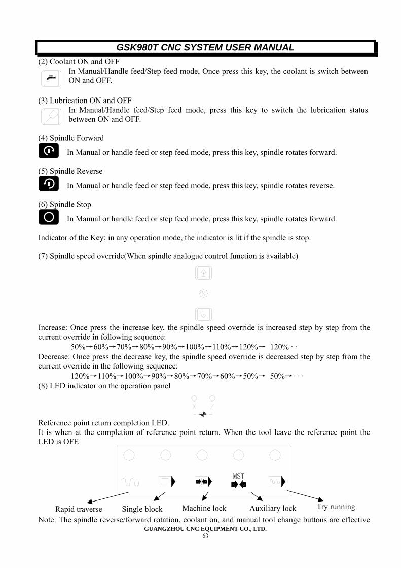
GSK980T CNC SYSTEM USER MANUAL
GUANGZHOU CNC EQUIPMENT CO., LTD. 63
(2) Coolant ON and OFF In Manual/Handle feed/Step feed mode, Once press this key, the coolant is switch between ON and OFF.
(3) Lubrication ON and OFF In Manual/Handle feed/Step feed mode, press this key to switch the lubrication status between ON and OFF.
(4) Spindle Forward
In Manual or handle feed or step feed mode, press this key, spindle rotates forward. (5) Spindle Reverse
In Manual or handle feed or step feed mode, press this key, spindle rotates reverse. (6) Spindle Stop
In Manual or handle feed or step feed mode, press this key, spindle rotates forward. Indicator of the Key: in any operation mode, the indicator is lit if the spindle is stop. (7) Spindle speed override(When spindle analogue control function is available)
Increase: Once press the increase key, the spindle speed override is increased step by step from the current override in following sequence:
50%→60%→70%→80%→90%→100%→110%→120%→ 120% · · Decrease: Once press the decrease key, the spindle speed override is decreased step by step from the current override in the following sequence:
120%→110%→100%→90%→80%→70%→60%→50%→ 50%→· · · (8) LED indicator on the operation panel
Reference point return completion LED. It is when at the completion of reference point return. When the tool leave the reference point the LED is OFF.
MST
Note: The spindle reverse/forward rotation, coolant on, and manual tool change buttons are effective
Rapid traverse Single block Machine lock Auxiliary lock Try running
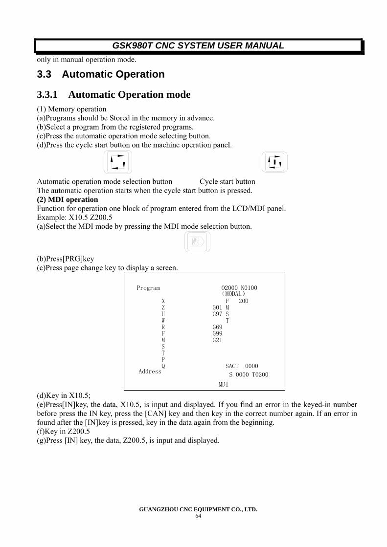
GSK980T CNC SYSTEM USER MANUAL
GUANGZHOU CNC EQUIPMENT CO., LTD. 64
only in manual operation mode.
3.3 Automatic Operation
3.3.1 Automatic Operation mode (1) Memory operation (a)Programs should be Stored in the memory in advance. (b)Select a program from the registered programs. (c)Press the automatic operation mode selecting button. (d)Press the cycle start button on the machine operation panel.
Automatic operation mode selection button Cycle start button The automatic operation starts when the cycle start button is pressed. (2) MDI operation Function for operation one block of program entered from the LCD/MDI panel. Example: X10.5 Z200.5 (a)Select the MDI mode by pressing the MDI mode selection button.
(b)Press[PRG]key (c)Press page change key to display a screen.
Program O2000 N0100
Address
MDI
(MODAL) X Z U W R F M S T P Q
F 200 G01 MG97 S TG69G99G21
SACT 0000
S 0000 T0200
(d)Key in X10.5; (e)Press[IN]key, the data, X10.5, is input and displayed. If you find an error in the keyed-in number before press the IN key, press the [CAN] key and then key in the correct number again. If an error in found after the [IN]key is pressed, key in the data again from the beginning. (f)Key in Z200.5 (g)Press [IN] key, the data, Z200.5, is input and displayed.
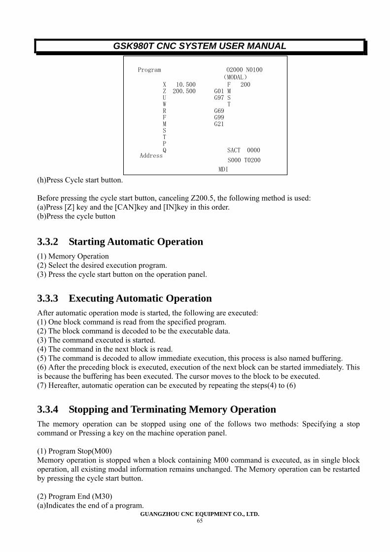
GSK980T CNC SYSTEM USER MANUAL
GUANGZHOU CNC EQUIPMENT CO., LTD. 65
Program O2000 N0100
Address
MDI
(MODAL) X 10.500 Z 200.500 U W R F M S T P Q
F 200 G01 MG97 S TG69G99G21
SACT 0000
S000 T0200
(h)Press Cycle start button. Before pressing the cycle start button, canceling Z200.5, the following method is used: (a)Press [Z] key and the [CAN]key and [IN]key in this order. (b)Press the cycle button
3.3.2 Starting Automatic Operation (1) Memory Operation (2) Select the desired execution program. (3) Press the cycle start button on the operation panel.
3.3.3 Executing Automatic Operation After automatic operation mode is started, the following are executed: (1) One block command is read from the specified program. (2) The block command is decoded to be the executable data. (3) The command executed is started. (4) The command in the next block is read. (5) The command is decoded to allow immediate execution, this process is also named buffering. (6) After the preceding block is executed, execution of the next block can be started immediately. This is because the buffering has been executed. The cursor moves to the block to be executed. (7) Hereafter, automatic operation can be executed by repeating the steps(4) to (6)
3.3.4 Stopping and Terminating Memory Operation The memory operation can be stopped using one of the follows two methods: Specifying a stop command or Pressing a key on the machine operation panel. (1) Program Stop(M00) Memory operation is stopped when a block containing M00 command is executed, as in single block operation, all existing modal information remains unchanged. The Memory operation can be restarted by pressing the cycle start button. (2) Program End (M30) (a)Indicates the end of a program.
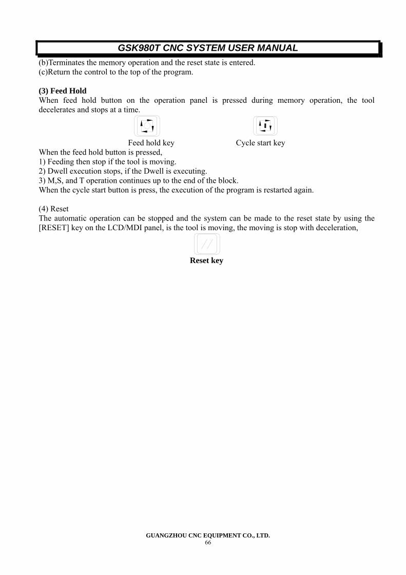
GSK980T CNC SYSTEM USER MANUAL
GUANGZHOU CNC EQUIPMENT CO., LTD. 66
(b)Terminates the memory operation and the reset state is entered. (c)Return the control to the top of the program. (3) Feed Hold When feed hold button on the operation panel is pressed during memory operation, the tool decelerates and stops at a time.
Feed hold key Cycle start key
When the feed hold button is pressed, 1) Feeding then stop if the tool is moving. 2) Dwell execution stops, if the Dwell is executing. 3) M,S, and T operation continues up to the end of the block. When the cycle start button is press, the execution of the program is restarted again. (4) Reset The automatic operation can be stopped and the system can be made to the reset state by using the [RESET] key on the LCD/MDI panel, is the tool is moving, the moving is stop with deceleration,
Reset key
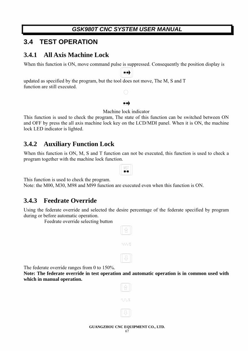
GSK980T CNC SYSTEM USER MANUAL
GUANGZHOU CNC EQUIPMENT CO., LTD. 67
3.4 TEST OPERATION
3.4.1 All Axis Machine Lock When this function is ON, move command pulse is suppressed. Consequently the position display is
updated as specified by the program, but the tool does not move, The M, S and T function are still executed.
Machine lock indicator
This function is used to check the program, The state of this function can be switched between ON and OFF by press the all axis machine lock key on the LCD/MDI panel. When it is ON, the machine lock LED indicator is lighted.
3.4.2 Auxiliary Function Lock When this function is ON, M, S and T function can not be executed, this function is used to check a program together with the machine lock function.
This function is used to check the program. Note: the M00, M30, M98 and M99 function are executed even when this function is ON.
3.4.3 Feedrate Override Using the federate override and selected the desire percentage of the federate specified by program during or before automatic operation.
Feedrate override selecting button
The federate override ranges from 0 to 150%. Note: The federate override in test operation and automatic operation is in common used with which in manual operation.
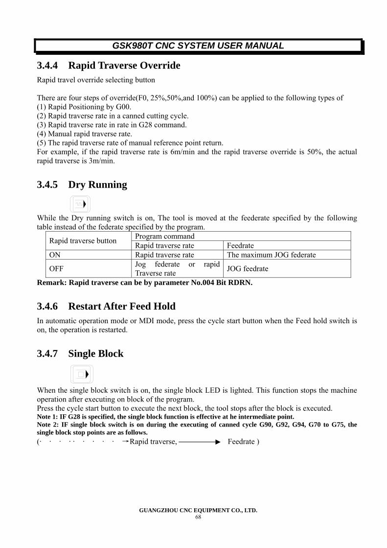
GSK980T CNC SYSTEM USER MANUAL
GUANGZHOU CNC EQUIPMENT CO., LTD. 68
3.4.4 Rapid Traverse Override Rapid travel override selecting button There are four steps of override(F0, 25%,50%,and 100%) can be applied to the following types of (1) Rapid Positioning by G00. (2) Rapid traverse rate in a canned cutting cycle. (3) Rapid traverse rate in rate in G28 command. (4) Manual rapid traverse rate. (5) The rapid traverse rate of manual reference point return. For example, if the rapid traverse rate is 6m/min and the rapid traverse override is 50%, the actual rapid traverse is 3m/min.
3.4.5 Dry Running
While the Dry running switch is on, The tool is moved at the feederate specified by the following table instead of the federate specified by the program.
Program command Rapid traverse button Rapid traverse rate Feedrate ON Rapid traverse rate The maximum JOG federate
OFF Jog federate or rapid Traverse rate JOG feedrate
Remark: Rapid traverse can be by parameter No.004 Bit RDRN.
3.4.6 Restart After Feed Hold In automatic operation mode or MDI mode, press the cycle start button when the Feed hold switch is on, the operation is restarted.
3.4.7 Single Block
When the single block switch is on, the single block LED is lighted. This function stops the machine operation after executing on block of the program. Press the cycle start button to execute the next block, the tool stops after the block is executed. Note 1: IF G28 is specified, the single block function is effective at he intermediate point. Note 2: IF single block switch is on during the executing of canned cycle G90, G92, G94, G70 to G75, the single block stop points are as follows. (· · · · · · · · · →Rapid traverse, Feedrate )
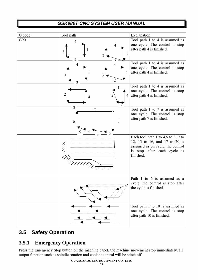
GSK980T CNC SYSTEM USER MANUAL
GUANGZHOU CNC EQUIPMENT CO., LTD. 69
G code Tool path Explanation G90
Tool path 1 to 4 is assumed as one cycle. The control is stop after path 4 is finished.
Tool path 1 to 4 is assumed as one cycle. The control is stop after path 4 is finished.
Tool path 1 to 4 is assumed as one cycle. The control is stop after path 4 is finished.
Tool path 1 to 7 is assumed as one cycle. The control is stop after path 7 is finished.
Each tool path 1 to 4,5 to 8, 9 to 12, 13 to 16, and 17 to 20 is assumed as on cycle, the control is stop after each cycle is finished.
Path 1 to 6 is assumed as a cycle, the control is stop after the cycle is finished.
Tool path 1 to 10 is assumed as one cycle. The control is stop after path 10 is finished.
3.5 Safety Operation
3.5.1 Emergency Operation Press the Emergency Stop button on the machine panel, the machine movement stop immediately, all output function such as spindle rotation and coolant control will be stitch off.
2
1
4
3
2
1
4
3
2
1
4
3
2
1
4
3
1
4
3
2 2
1
4
3
24
7
1
35
6
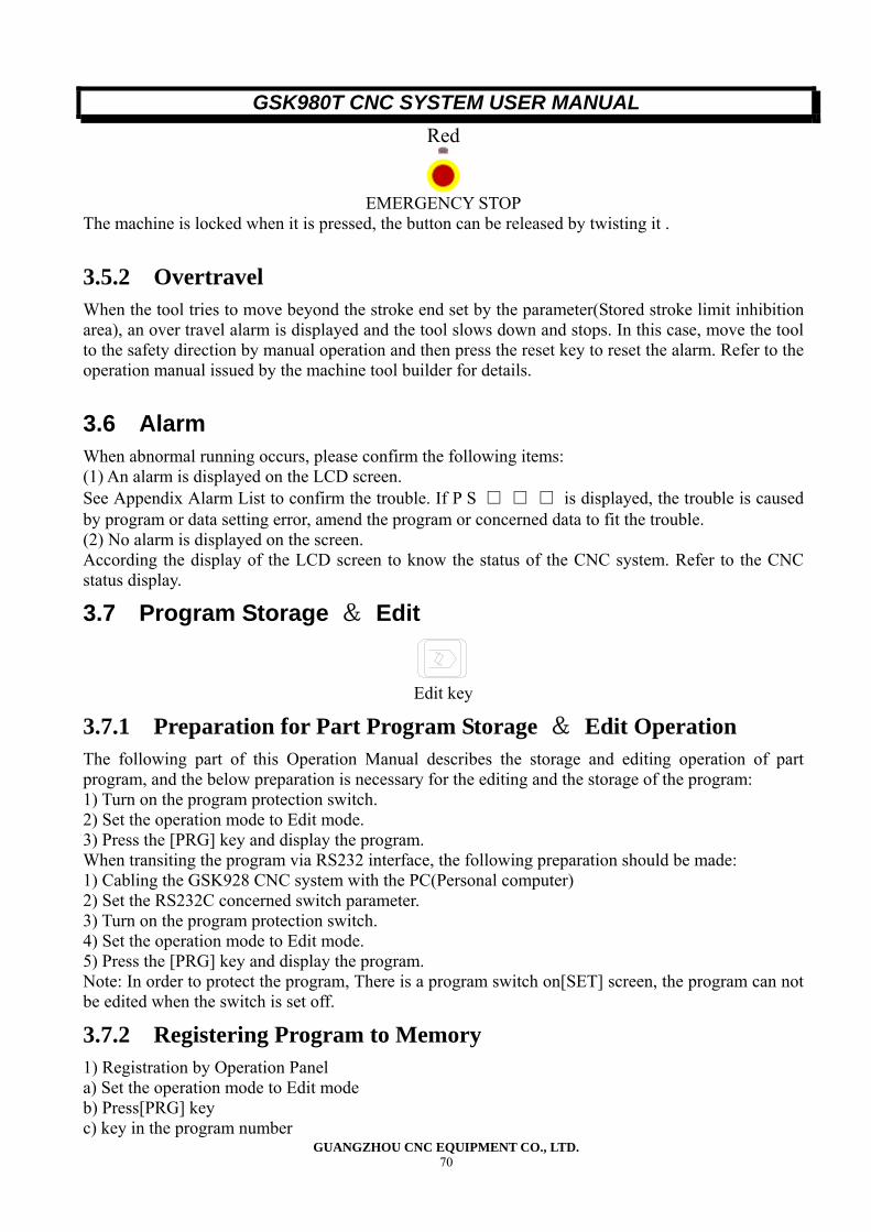
GSK980T CNC SYSTEM USER MANUAL
GUANGZHOU CNC EQUIPMENT CO., LTD. 70
Red
EMERGENCY STOP
The machine is locked when it is pressed, the button can be released by twisting it .
3.5.2 Overtravel When the tool tries to move beyond the stroke end set by the parameter(Stored stroke limit inhibition area), an over travel alarm is displayed and the tool slows down and stops. In this case, move the tool to the safety direction by manual operation and then press the reset key to reset the alarm. Refer to the operation manual issued by the machine tool builder for details.
3.6 Alarm When abnormal running occurs, please confirm the following items: (1) An alarm is displayed on the LCD screen. See Appendix Alarm List to confirm the trouble. If P S □ □ □ is displayed, the trouble is caused by program or data setting error, amend the program or concerned data to fit the trouble. (2) No alarm is displayed on the screen. According the display of the LCD screen to know the status of the CNC system. Refer to the CNC status display.
3.7 Program Storage & Edit
Edit key
3.7.1 Preparation for Part Program Storage & Edit Operation The following part of this Operation Manual describes the storage and editing operation of part program, and the below preparation is necessary for the editing and the storage of the program: 1) Turn on the program protection switch. 2) Set the operation mode to Edit mode. 3) Press the [PRG] key and display the program. When transiting the program via RS232 interface, the following preparation should be made: 1) Cabling the GSK928 CNC system with the PC(Personal computer) 2) Set the RS232C concerned switch parameter. 3) Turn on the program protection switch. 4) Set the operation mode to Edit mode. 5) Press the [PRG] key and display the program. Note: In order to protect the program, There is a program switch on[SET] screen, the program can not be edited when the switch is set off.
3.7.2 Registering Program to Memory 1) Registration by Operation Panel a) Set the operation mode to Edit mode b) Press[PRG] key c) key in the program number
GSK980T CNC SYSTEM USER MANUAL
GUANGZHOU CNC EQUIPMENT CO., LTD. 71
e) Press [EOB] key With the above procedure, the program number is registered to the memory, and then key in the words of the program and press [INSRT] key to register(refer to the section of Inserting the Word). 2) Registration from PC a) Set the operation mode to Edit mode. b) Press[PRG] key and display the Program screen. c) key in the address O and the program number. d) Start the PC and set it to output mode. e) Press[IN] key to register the program to memory, when registering is processing, [Input is twinkling on the screen.
3.7.3 Program Number Searching When there are many programs in the memory, when the[PRG] key is press, the pointer always point to one of the program number, even though the power is turn off, the program pointer is not lose. The desired program can be called by program number searching. 1) Searching Method 1 a) Set the operation mode to Edit mode b) Press [PRG] key and display the program screen. c) Press[O] key, d) Key in the program number to be searched. e) Push [↓] key . f) When searching is over, the program number searched is displayed at the right top of the LCD screen. 2) Searching Method 2 a) Set operation mode to Edit mode or Automatic Operation mode. b) Press [PRG] key c) Press[O] key d) Press [↓] key, in the Edit mode, if the [O], [↓] keys are pushed tautologically, the registered programs are displayed sequentially.
3.7.4 Deleting Program The deleting operation is used to delete the program in the memory. 1) Set the operation mode to Edit mode. 2) Press the [PRG] key and display the program screen. 3) Press [O] key 4) Press[DEL] key, the program with the key in number is deleted.
3.7.5 Deleting All Program The operation is used to delete the program in the memory. 1) Set the operation mode to Edit mode. 2) Press the [PRG] key and display the program screen . 3) Press[O]key, 4) Key in [--], [9], [9],[9],[9] and then press[DEL] key.
GSK980T CNC SYSTEM USER MANUAL
GUANGZHOU CNC EQUIPMENT CO., LTD. 72
3.7.6 Output a program This operation is used to output a program in the memory to the PC. 1) Enabling the GSD980 and PC. 2) Setting the output code(ISO) 3) Set the operation mode to Edit mode. 4) Press[PRG] key to display the program screen. 5) Make the PC ready. 6) Press [O] key . 7) Key in the desired program number and then press[OUT] key.
3.7.7 Output All Programs This operation is used to output all programs in the memory to the PC. 1) Enabling the GSK980 and PC. 2) Setting the output code(ISO). 3) Set the operation mode to Edit mode. 4) Press [PRG] key to display the program screen. 5) Make the PC ready. 6) Press[O] key . 7) Key in [--], [9],[9],[9],[9], and then press[OUT] key. Note: pressing [∥] key can halt the outputting.
3.7.8 Sequence Number Search This operation is used to find a sequence number in one program. It is usually used to edit or start the program at the block of that sequence number. The block or blocks skipped during the searching dose not affect the status of the CNC. It is to say that the coordinate values, M, S, T code of the skipped do not affect the coordinate values and the modal values of the CNC system. So specify the necessary M, S, T code and coordinate system setting etc, in the first block of which the program is to be started or restart with the sequence number searched. The block to be searched by sequence number search is usually at break point of the procedure of the part. If it is necessary to search and start a program from a d3esired block during program process, examine the condition of the CNC system and the machine tool. The specify of the necessary M, S, T code, coordinate system setting, etc, can be made from MDI panel. a) Set the operation mode to Edit mode. b) Press [PRG] key to display the program screen. c) Select the program number of which the sequence number to be searched d) Press[N] key e) Key in the desired sequence number. f) Press [↓] key . g) When the searching is over, the sequence number searched is displayed at the right top of the LCD screen. Note: During program search, M98××××(subprogram call) is not executed, so a search for a sequence number within a subprogram called from a currently selected program in Automatic Operation mode generates P/S alarm( alarm No060)
GSK980T CNC SYSTEM USER MANUAL
GUANGZHOU CNC EQUIPMENT CO., LTD. 73
O1000 ;
M98 P8000 ; N8888
M99 ;
Subprogram O8000 ;
In the above example, search for N8888 will generate an alarm.
3.7.9 Inserting, Amending and Deleting of word This function is used to modify the content of a program in the memory. a) Set the operation mode to Edit mode. b) Press[PRG] key to display the program screen. c) select the desired program. d) Search the word to be modified. A scan or a word search can be used. e) Inset, amend or delete the word . (1) Word Search a) Word scan Scan word by word.
N100 X100.0 Z120.0 ; M03; N110 M30 ;
1) Press the [↓] key, the cursor moves forward word by word on the screen. The cursor is displayed below the address character of the selected word. 2) Press the [↑] key, the cursor moves backward word by word on the screen.
N100 X100.0 Z120.0 ; M03 ; N110 M30 ;
3) Keep pressing the cursor key can move the cursor continuously. 4) Press the page change key ↓ to display the following page and search the first word of the page. 5) Press the page change key ↑to display the preceding page and search the first word of the page. 6) Keep press the page change key can display one page after another. b) Word Search A specified word is searched for from the current position in the forward or backward direction.
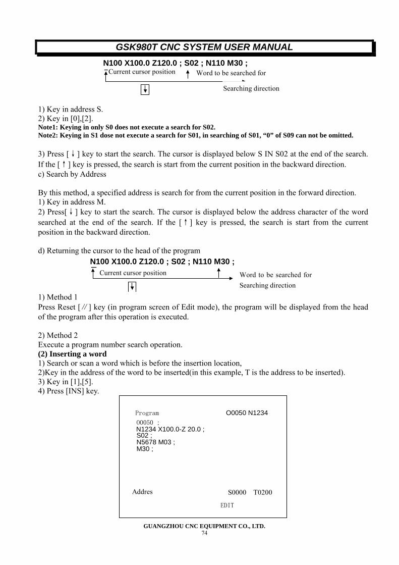
GSK980T CNC SYSTEM USER MANUAL
GUANGZHOU CNC EQUIPMENT CO., LTD. 74
Word to be searched forCurrent cursor position
Searching direction
N100 X100.0 Z120.0 ; S02 ; N110 M30 ;
1) Key in address S. 2) Key in [0],[2]. Note1: Keying in only S0 does not execute a search for S02. Note2: Keying in S1 dose not execute a search for S01, in searching of S01, “0” of S09 can not be omitted. 3) Press [↓] key to start the search. The cursor is displayed below S IN S02 at the end of the search. If the [↑] key is pressed, the search is start from the current position in the backward direction. c) Search by Address By this method, a specified address is search for from the current position in the forward direction. 1) Key in address M. 2) Press[↓] key to start the search. The cursor is displayed below the address character of the word searched at the end of the search. If the [↑] key is pressed, the search is start from the current position in the backward direction. d) Returning the cursor to the head of the program
Current cursor position Word to be searched for
Searching direction
N100 X100.0 Z120.0 ; S02 ; N110 M30 ;
1) Method 1 Press Reset [∥] key (in program screen of Edit mode), the program will be displayed from the head of the program after this operation is executed. 2) Method 2 Execute a program number search operation. (2) Inserting a word 1) Search or scan a word which is before the insertion location, 2)Key in the address of the word to be inserted(in this example, T is the address to be inserted). 3) Key in [1],[5]. 4) Press [INS] key.
Program O0050 N1234
EDIT
Addres S0000 T0200
O0050 ; N1234 X100.0-Z 20.0 ; S02 ; N5678 M03 ;M30 ;
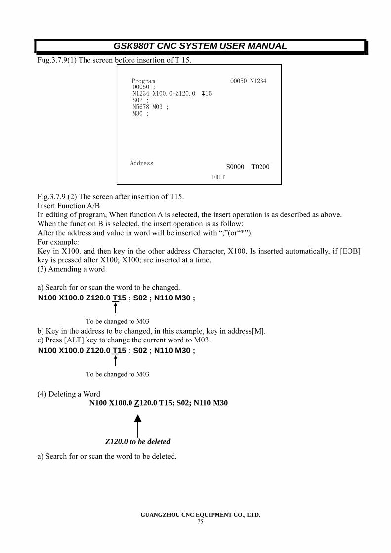
GSK980T CNC SYSTEM USER MANUAL
GUANGZHOU CNC EQUIPMENT CO., LTD. 75
Fug.3.7.9(1) The screen before insertion of T 15.
Program O0050 N1234
EDIT
Address
S0000 T0200
O0050 ; N1234 X100.0-Z120.0 T15 S02 ; N5678 M03 ; M30 ;
Fig.3.7.9 (2) The screen after insertion of T15. Insert Function A/B In editing of program, When function A is selected, the insert operation is as described as above. When the function B is selected, the insert operation is as follow: After the address and value in word will be inserted with “;”(or“*”). For example: Key in X100. and then key in the other address Character, X100. Is inserted automatically, if [EOB] key is pressed after X100; X100; are inserted at a time. (3) Amending a word a) Search for or scan the word to be changed.
To be changed to M03
N100 X100.0 Z120.0 T15 ; S02 ; N110 M30 ;
b) Key in the address to be changed, in this example, key in address[M]. c) Press [ALT] key to change the current word to M03.
To be changed to M03
N100 X100.0 Z120.0 T15 ; S02 ; N110 M30 ;
(4) Deleting a Word a) Search for or scan the word to be deleted.
N100 X100.0 Z120.0 T15; S02; N110 M30
Z120.0 to be deleted
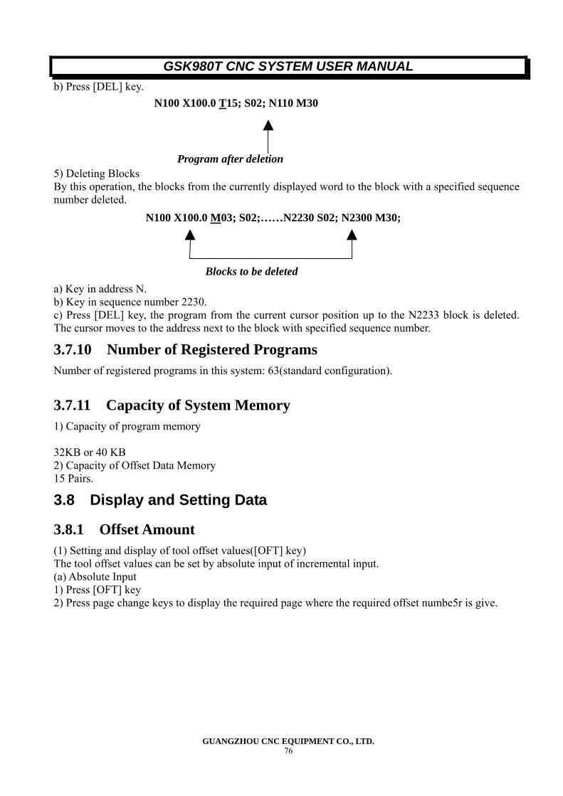
GSK980T CNC SYSTEM USER MANUAL
GUANGZHOU CNC EQUIPMENT CO., LTD. 76
b) Press [DEL] key. 5) Deleting Blocks By this operation, the blocks from the currently displayed word to the block with a specified sequence number deleted. a) Key in address N. b) Key in sequence number 2230. c) Press [DEL] key, the program from the current cursor position up to the N2233 block is deleted. The cursor moves to the address next to the block with specified sequence number.
3.7.10 Number of Registered Programs Number of registered programs in this system: 63(standard configuration).
3.7.11 Capacity of System Memory 1) Capacity of program memory 32KB or 40 KB 2) Capacity of Offset Data Memory 15 Pairs.
3.8 Display and Setting Data
3.8.1 Offset Amount (1) Setting and display of tool offset values([OFT] key) The tool offset values can be set by absolute input of incremental input. (a) Absolute Input 1) Press [OFT] key 2) Press page change keys to display the required page where the required offset numbe5r is give.
N100 X100.0 T15; S02; N110 M30
Program after deletion
N100 X100.0 M03; S02;……N2230 S02; N2300 M30;
Blocks to be deleted
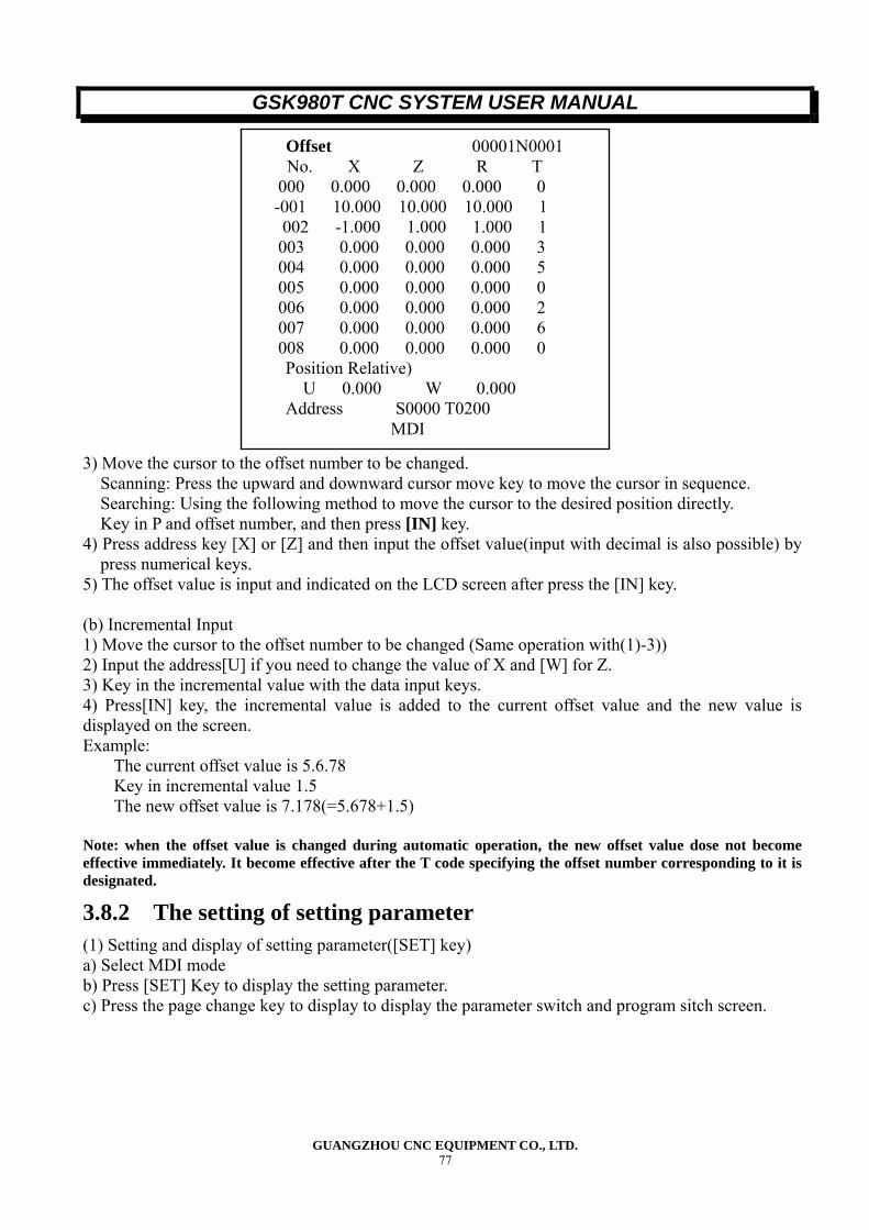
GSK980T CNC SYSTEM USER MANUAL
GUANGZHOU CNC EQUIPMENT CO., LTD. 77
3) Move the cursor to the offset number to be changed. Scanning: Press the upward and downward cursor move key to move the cursor in sequence.
Searching: Using the following method to move the cursor to the desired position directly. Key in P and offset number, and then press [IN] key.
4) Press address key [X] or [Z] and then input the offset value(input with decimal is also possible) by press numerical keys.
5) The offset value is input and indicated on the LCD screen after press the [IN] key. (b) Incremental Input 1) Move the cursor to the offset number to be changed (Same operation with(1)-3)) 2) Input the address[U] if you need to change the value of X and [W] for Z. 3) Key in the incremental value with the data input keys. 4) Press[IN] key, the incremental value is added to the current offset value and the new value is displayed on the screen. Example:
The current offset value is 5.6.78 Key in incremental value 1.5 The new offset value is 7.178(=5.678+1.5)
Note: when the offset value is changed during automatic operation, the new offset value dose not become effective immediately. It become effective after the T code specifying the offset number corresponding to it is designated.
3.8.2 The setting of setting parameter (1) Setting and display of setting parameter([SET] key) a) Select MDI mode b) Press [SET] Key to display the setting parameter. c) Press the page change key to display to display the parameter switch and program sitch screen.
Offset 00001N0001 No. X Z R T
000 0.000 0.000 0.000 0 -001 10.000 10.000 10.000 1 002 -1.000 1.000 1.000 1 003 0.000 0.000 0.000 3 004 0.000 0.000 0.000 5 005 0.000 0.000 0.000 0 006 0.000 0.000 0.000 2 007 0.000 0.000 0.000 6 008 0.000 0.000 0.000 0 Position Relative) U 0.000 W 0.000 Address S0000 T0200 MDI
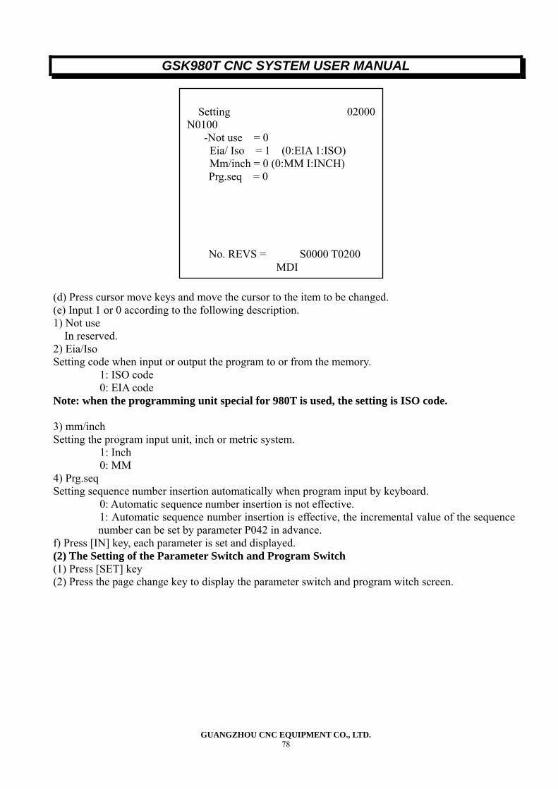
GSK980T CNC SYSTEM USER MANUAL
GUANGZHOU CNC EQUIPMENT CO., LTD. 78
(d) Press cursor move keys and move the cursor to the item to be changed. (e) Input 1 or 0 according to the following description. 1) Not use In reserved. 2) Eia/Iso Setting code when input or output the program to or from the memory.
1: ISO code 0: EIA code
Note: when the programming unit special for 980T is used, the setting is ISO code. 3) mm/inch Setting the program input unit, inch or metric system.
1: Inch 0: MM
4) Prg.seq Setting sequence number insertion automatically when program input by keyboard.
0: Automatic sequence number insertion is not effective. 1: Automatic sequence number insertion is effective, the incremental value of the sequence number can be set by parameter P042 in advance.
f) Press [IN] key, each parameter is set and displayed. (2) The Setting of the Parameter Switch and Program Switch (1) Press [SET] key (2) Press the page change key to display the parameter switch and program witch screen.
Setting 02000
N0100 -Not use = 0 Eia/ Iso = 1 (0:EIA 1:ISO) Mm/inch = 0 (0:MM I:INCH) Prg.seq = 0 No. REVS = S0000 T0200 MDI
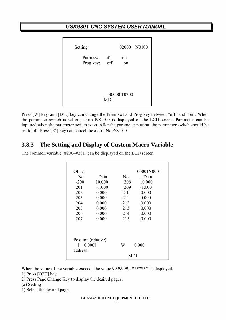
GSK980T CNC SYSTEM USER MANUAL
GUANGZHOU CNC EQUIPMENT CO., LTD. 79
Press [W] key, and [D/L] key can change the Pram swt and Prog key between “off” and “on”. When the parameter switch is set on, alarm P/S 100 is displayed on the LCD screen. Parameter can be inputted when the parameter switch is on. After the parameter putting, the parameter switch should be set to off. Press [∥] key can cancel the alarm No.P/S 100.
3.8.3 The Setting and Display of Custom Macro Variable The common variable (#200~#231) can be displayed on the LCD screen. When the value of the variable exceeds the value 9999999, ‘*******’ is displayed. 1) Press [OFT] key 2) Press Page Change Key to display the desired pages. (2) Setting 1) Select the desired page.
Setting 02000 N0100
Parm swt: off on Prog key: off on
S0000 T0200
MDI
Offset 00001N0001
No. Data No. Data -200 10.000 208 10.000 201 -1.000 209 -1.000
202 0.000 210 0.000 203 0.000 211 0.000 204 0.000 212 0.000 205 0.000 213 0.000 206 0.000 214 0.000 207 0.000 215 0.000
Position (relative) [ 0.000] W 0.000 address
MDI
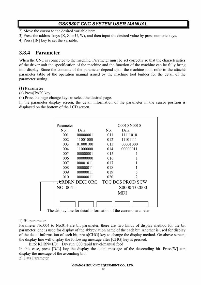
GSK980T CNC SYSTEM USER MANUAL
GUANGZHOU CNC EQUIPMENT CO., LTD. 80
2) Move the cursor to the desired variable item. 3) Press the address keys (X, Z or U, W), and then input the desired value by press numeric keys. 4) Press [IN] key to set the variable.
3.8.4 Parameter When the CNC is connected to the machine, Parameter must be set correctly so that the characteristics of the driver unit the specification of the machine and the function of the machine can be fully bring into display. Since the contents of the parameter depend upon the machine tool, refer to the attaché parameter table of the operation manual issued by the machine tool builder for the detail of the parameter setting. (1) Parameter (a) Press[PAR] key (b) Press the page change keys to select the desired page. In the parameter display screen, the detail information of the parameter in the cursor position is displayed on the bottom of the LCD screen. 1) Bit parameter Parameter No.004 to No.014 are bit parameter, there are two kinds of display method for the bit parameter: one is used for display of the abbreviation name of the each bit. Another is used for display of the detail information of each bit, press[CHG] key to change the display method. On above screen, the display line will display the following message after [CHG] key is pressed.
Bit6: RDRN=1/0: Dry run G00 rapid travel/manual feed In this case, press [D/L] key the display the detail message of the descending bit. Press[W] can display the message of the ascending bit . 2) Data Parameter
Parameter O0010 N0010
No.. Data No. Data 001 00000001 011 11111010 002 11001000 012 11101111 003 01000100 013 00001000 _004 11000000 014 00000011 005 00000001 015 1 006 00000000 016 1 007 00001011 017 1 008 00000011 018 1 009 00000011 019 5 010 00000011 020 2
…RDRN DECI ORC TOC DCS PROD SCW NO. 004 = S0000 T02000 MDI
The display line for detail information of the current parameter
GSK980T CNC SYSTEM USER MANUAL
GUANGZHOU CNC EQUIPMENT CO., LTD. 81
In data parameter, only one data can be set. For example, when the cursor moves to parameter No.15, the message is follow:
X command numerator. (2) Parameter Setting Parameter can be set by MDI panel or input from PC (personal computer). (a) Parameter Setting by MDI Panel 1) Set the parameter switch to on. 2) Select MDI operation mode (or the emergency stop button is pressed) 3) Press[PAR] key to display parameter screen. 4) Press page change key to display the page with the desired parameter. 5) Move the cursor to the position of the desired parameter. Method 1: Press [↓] or [↑] key to shift the cursor to the position of the desired parameter. If the cursor key is depressed continuously, the cursor shifts sequentially. If the cursor exceeds a page, the previous/next page appears on the screen. Method 2: Input [P] [parameter number] and [IN] (step 4 can be omitted) 6) Key in the parameter by data input keys. 7) Press [IN] key, the parameter value is input and displayed. 8) After all parameter have been set and confirmed, select the parameter switch and program switch screens and set the parameter switch to off. 9) Press the Reset [∥] key to cancel the alarm, when alarm No.000 has occurred, turn off the power supply of the CNC system and turn it on.. (b) Input Parameter from PC The method is effective only when the input /output interface option function is combined. 1) The file is head by “%LF”. 2) The format of parameter number and parameter value are as follows: N__ P__ LF(N- parameter number, P-parameter value) Step (b) can be repeated according to requirement. The leading zero of the parameter value can be omitted. 3) The file is ended by “LF” or “%”.Data input is finished when these codes are input. Parameter not specified on the file remains unchanged even if the parameter setting file is input from PC. The parameter setting file prepared by the above procedure can be input according to the following procedure: 1) Set the parameter switch to on. 2) Select Edit operation mode. 3) Select parameter screen, and make the programming unit stand by to output.(Refer to the Operation Manual of the programming unit). 4) Press [ IN] key to input the parameter setting, when the input is being processed, “Input ” is flickering in the status display line. 5) Set the parameter switch to off.. 6) Press Reset key. (If alarm No.000 occurred, turn off and on the power supply of the CNC system). Note1: When any of the following alarm is detected, the input is halted: 1) An address other than N and P was input . 2) The value of N or P is not correct. Note2: If it is desired to halt the parameter setting file input, press Reset key . Note3: Apart of parameters do not become effective until the power supply is turn off and turn on (When alarm No.000 occurred) Note4: Parameter related to the RS232C interface must be set from MDI operation panel before inputting parameter from PC.
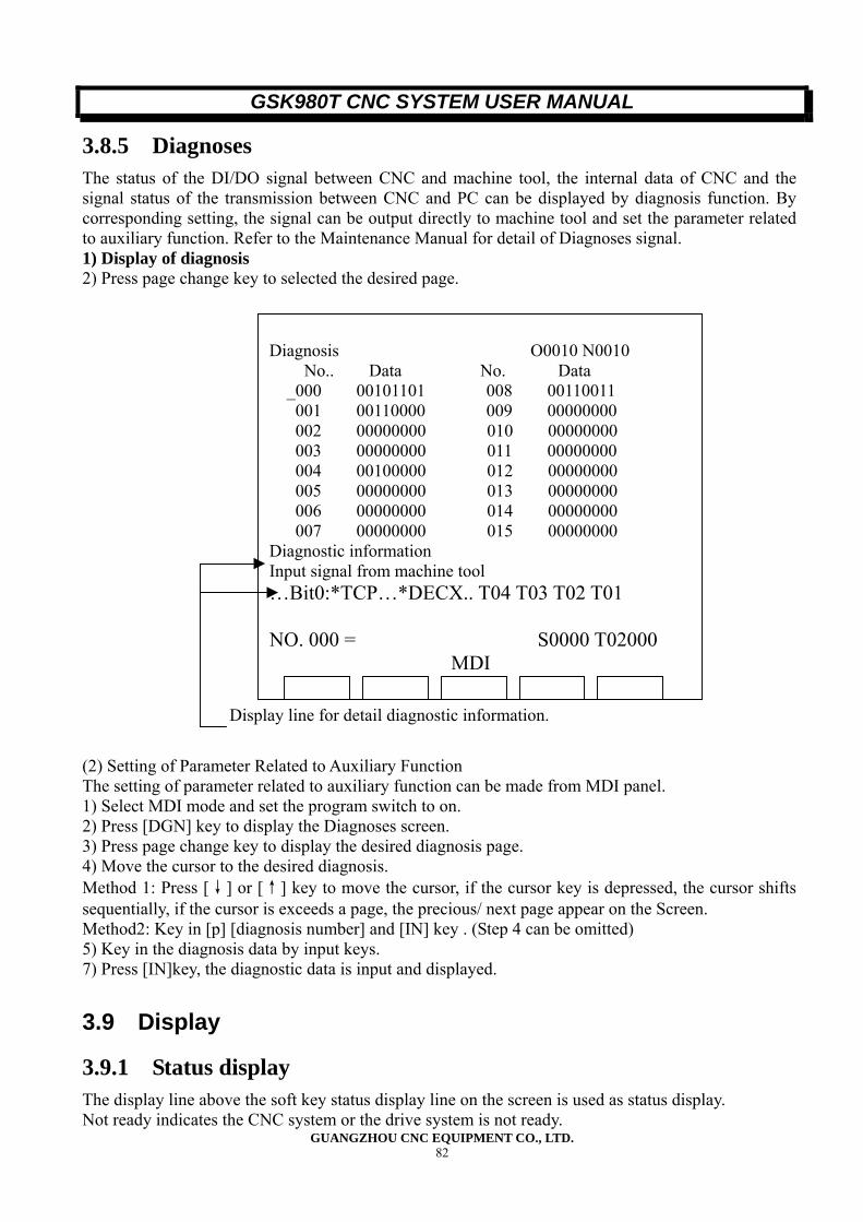
GSK980T CNC SYSTEM USER MANUAL
GUANGZHOU CNC EQUIPMENT CO., LTD. 82
3.8.5 Diagnoses The status of the DI/DO signal between CNC and machine tool, the internal data of CNC and the signal status of the transmission between CNC and PC can be displayed by diagnosis function. By corresponding setting, the signal can be output directly to machine tool and set the parameter related to auxiliary function. Refer to the Maintenance Manual for detail of Diagnoses signal. 1) Display of diagnosis 2) Press page change key to selected the desired page. (2) Setting of Parameter Related to Auxiliary Function The setting of parameter related to auxiliary function can be made from MDI panel. 1) Select MDI mode and set the program switch to on. 2) Press [DGN] key to display the Diagnoses screen. 3) Press page change key to display the desired diagnosis page. 4) Move the cursor to the desired diagnosis. Method 1: Press [↓] or [↑] key to move the cursor, if the cursor key is depressed, the cursor shifts sequentially, if the cursor is exceeds a page, the precious/ next page appear on the Screen. Method2: Key in [p] [diagnosis number] and [IN] key . (Step 4 can be omitted) 5) Key in the diagnosis data by input keys. 7) Press [IN]key, the diagnostic data is input and displayed.
3.9 Display
3.9.1 Status display The display line above the soft key status display line on the screen is used as status display. Not ready indicates the CNC system or the drive system is not ready.
Diagnosis O0010 N0010
No.. Data No. Data _000 00101101 008 00110011 001 00110000 009 00000000 002 00000000 010 00000000 003 00000000 011 00000000
004 00100000 012 00000000 005 00000000 013 00000000 006 00000000 014 00000000 007 00000000 015 00000000
Diagnostic information Input signal from machine tool …Bit0:*TCP…*DECX.. T04 T03 T02 T01 NO. 000 = S0000 T02000 MDI
Display line for detail diagnostic information.
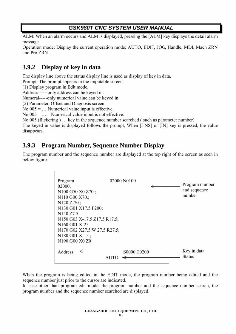
GSK980T CNC SYSTEM USER MANUAL
GUANGZHOU CNC EQUIPMENT CO., LTD. 83
ALM: When an alarm occurs and ALM is displayed, pressing the [ALM] key displays the detail alarm message. Operation mode: Display the current operation mode: AUTO, EDIT, JOG, Handle, MDI, Mach ZRN and Pro ZRN.
3.9.2 Display of key in data The display line above the status display line is used as display of key in data. Prompt: The prompt appears in the imputable screen. (1) Display program in Edit mode. Address------only address can be keyed in. Numeral-----only numerical value can be keyed in (2) Parameter, Offset and Diagnosis screen: No.005 = … Numerical value input is effective. No.005 … Numerical value input is not effective. No.005 (flickering ) … key in the sequence number searched ( such as parameter number) The keyed in value is displayed follows the prompt, When [I NS] or [IN] key is pressed, the value disappears.
3.9.3 Program Number, Sequence Number Display The program number and the sequence number are displayed at the top right of the screen as seen in below figure. When the program is being edited in the EDIT mode, the program number being edited and the sequence number just prior to the cursor are indicated. In case other than program edit mode, the program number and the sequence number search, the program number and the sequence number searched are displayed.
Program 02000 N0100 02000; N100 G50 X0 Z70.; N110 G00 X70.; N120 Z-70.; N130 G01 X17.5 F200; N140 Z7.5 N150 G03 X-17.5 Z17.5 R17.5; N160 G01 X-25 N170 G02 X27.5 W 27.5 R27.5; N180 G01 X-15.; N190 G00 X0 Z0 Address S0000 T0200 AUTO
Program numberand sequence number
Key in data Status
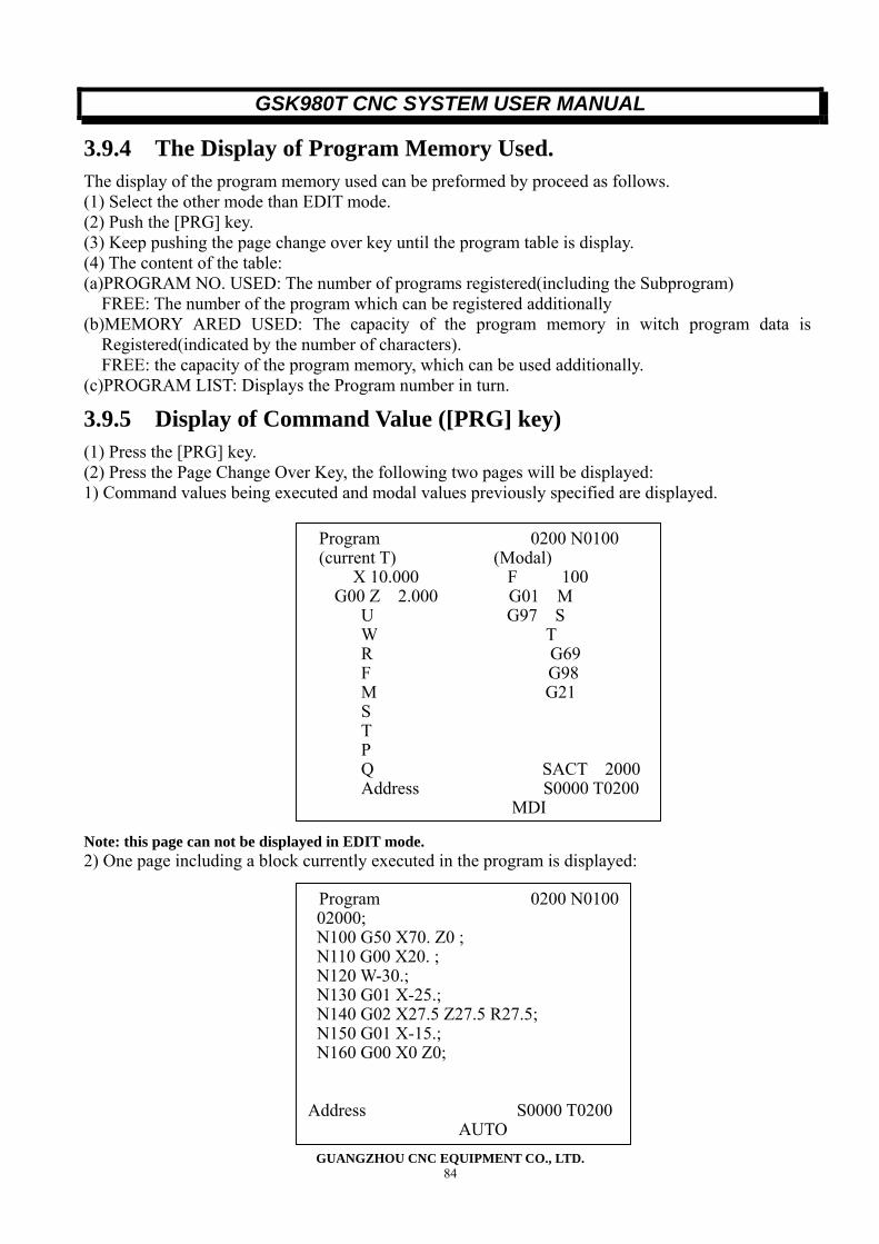
GSK980T CNC SYSTEM USER MANUAL
GUANGZHOU CNC EQUIPMENT CO., LTD. 84
3.9.4 The Display of Program Memory Used. The display of the program memory used can be preformed by proceed as follows. (1) Select the other mode than EDIT mode. (2) Push the [PRG] key. (3) Keep pushing the page change over key until the program table is display. (4) The content of the table: (a)PROGRAM NO. USED: The number of programs registered(including the Subprogram)
FREE: The number of the program which can be registered additionally (b)MEMORY ARED USED: The capacity of the program memory in witch program data is
Registered(indicated by the number of characters). FREE: the capacity of the program memory, which can be used additionally.
(c)PROGRAM LIST: Displays the Program number in turn.
3.9.5 Display of Command Value ([PRG] key) (1) Press the [PRG] key. (2) Press the Page Change Over Key, the following two pages will be displayed: 1) Command values being executed and modal values previously specified are displayed.
Note: this page can not be displayed in EDIT mode. 2) One page including a block currently executed in the program is displayed:
Program 0200 N0100(current T) (Modal)
X 10.000 F 100 G00 Z 2.000 G01 M
U G97 S W T R G69 F G98 M G21 S T P Q SACT 2000 Address S0000 T0200 MDI
Program 0200 N0100 02000; N100 G50 X70. Z0 ; N110 G00 X20. ; N120 W-30.; N130 G01 X-25.; N140 G02 X27.5 Z27.5 R27.5; N150 G01 X-15.; N160 G00 X0 Z0; Address S0000 T0200 AUTO
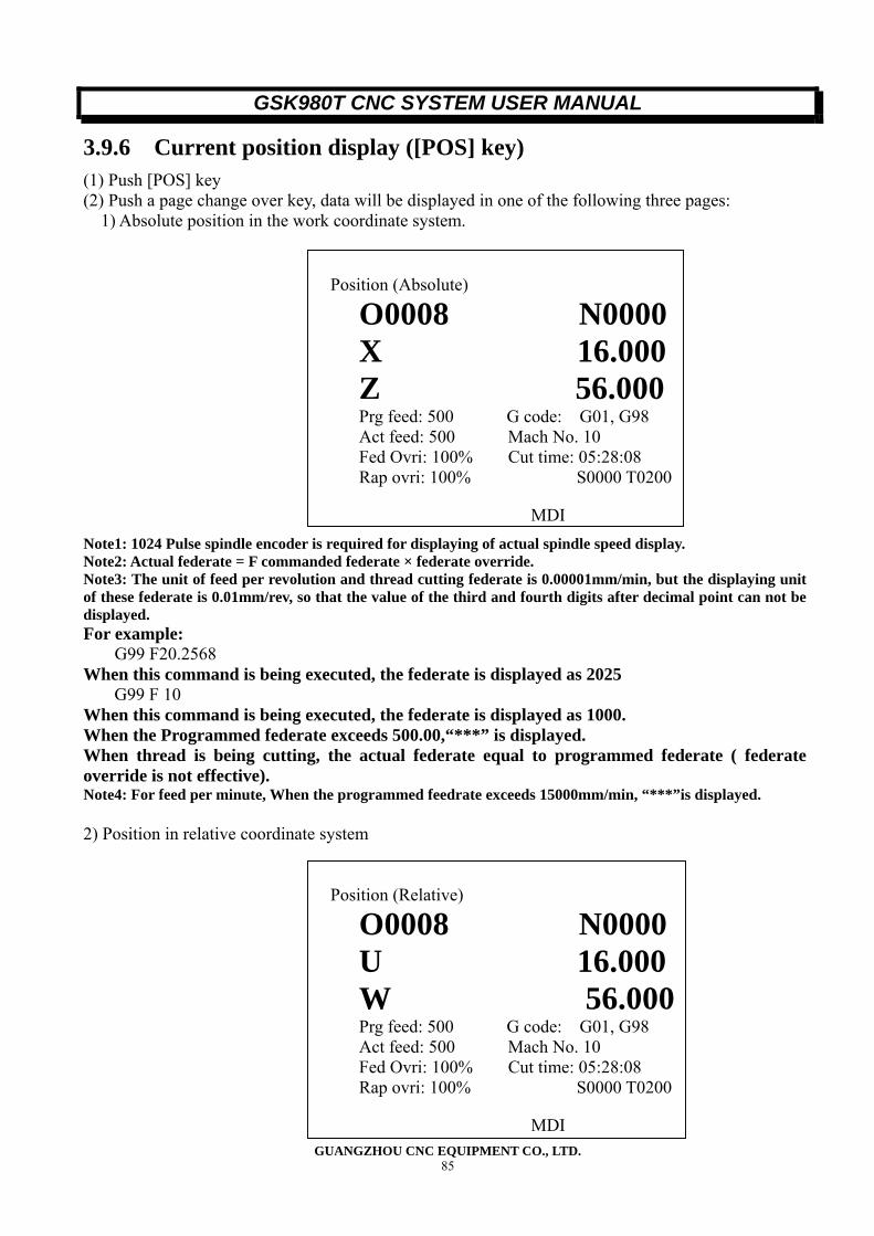
GSK980T CNC SYSTEM USER MANUAL
GUANGZHOU CNC EQUIPMENT CO., LTD. 85
3.9.6 Current position display ([POS] key) (1) Push [POS] key (2) Push a page change over key, data will be displayed in one of the following three pages: 1) Absolute position in the work coordinate system.
Note1: 1024 Pulse spindle encoder is required for displaying of actual spindle speed display. Note2: Actual federate = F commanded federate × federate override. Note3: The unit of feed per revolution and thread cutting federate is 0.00001mm/min, but the displaying unit of these federate is 0.01mm/rev, so that the value of the third and fourth digits after decimal point can not be displayed. For example:
G99 F20.2568 When this command is being executed, the federate is displayed as 2025
G99 F 10 When this command is being executed, the federate is displayed as 1000. When the Programmed federate exceeds 500.00,“***” is displayed. When thread is being cutting, the actual federate equal to programmed federate ( federate override is not effective). Note4: For feed per minute, When the programmed feedrate exceeds 15000mm/min, “***”is displayed. 2) Position in relative coordinate system
Position (Absolute)
O0008 N0000 X 16.000 Z 56.000 Prg feed: 500 G code: G01, G98 Act feed: 500 Mach No. 10 Fed Ovri: 100% Cut time: 05:28:08 Rap ovri: 100% S0000 T0200
MDI
Position (Relative)
O0008 N0000 U 16.000 W 56.000 Prg feed: 500 G code: G01, G98 Act feed: 500 Mach No. 10 Fed Ovri: 100% Cut time: 05:28:08 Rap ovri: 100% S0000 T0200
MDI
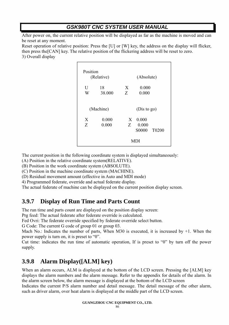
GSK980T CNC SYSTEM USER MANUAL
GUANGZHOU CNC EQUIPMENT CO., LTD. 86
After power on, the current relative position will be displayed as far as the machine is moved and can be reset at any moment. Reset operation of relative position: Press the [U] or [W] key, the address on the display will flicker, then press the[CAN] key. The relative position of the flickering address will be reset to zero. 3) Overall display The current position in the following coordinate system is displayed simultaneously: (A) Position in the relative coordinate system(RELATIVE). (B) Position in the work coordinate system (ABSOLUTE). (C) Position in the machine coordinate system (MACHINE). (D) Residual movement amount (effective in Auto and MDI mode) 4) Programmed federate, override and actual federate display. The actual federate of machine can be displayed on the current position display screen.
3.9.7 Display of Run Time and Parts Count The run time and parts count are displayed on the position display screen: Prg feed: The actual federate after federate override is calculated. Fed Ovri: The federate override specified by federate override select button. G Code: The current G code of group 01 or group 03. Mach No.: Indicates the number of parts, When M30 is executed, it is increased by +1. When the power supply is turn on, it is preset to “0”. Cut time: indicates the run time of automatic operation, If is preset to “0” by turn off the power supply.
3.9.8 Alarm Display([ALM] key) When an alarm occurs, ALM is displayed at the bottom of the LCD screen. Pressing the [ALM] key displays the alarm numbers and the alarm message. Refer to the appendix for details of the alarm. In the alarm screen below, the alarm message is displayed at the bottom of the LCD screen Indicates the current P/S alarm number and detail message. The detail message of the other alarm, such as driver alarm, over heat alarm is displayed at the middle part of the LCD screen.
Position
(Relative) (Absolute)
U 18 X 0.000 W 38.000 Z 0.000
(Machine) (Dis to go)
X 0.000 X 0.000 Z 0.000 Z 0.000 S0000 T0200
MDI
GSK980T CNC SYSTEM USER MANUAL
GUANGZHOU CNC EQUIPMENT CO., LTD. 87
Note: When an alarm occurs, the alarm message is automatically displayed on the screen.
3.9.9 Adjusting Brightness of LCD There are two kind of methods for adjusting brightness of the LCD: 1) Classifying adjusting: In the first page of Position screen (Relative Coordinate), Depress [U] key or [W] until Address U or W is flickering, Then press. [↓] key: become dark, (for the first time, the screen becomes light, afterwards, when the [↑] key is pressed once, the screen becomes darker) [↓] key: become lighter gradually 2) Adjust by adjustable resistor (option)
Alarm 02000 N0100
Program/ operation error: 007
P/S alarm: decimal point input error Alarm MDI
GSK980T CNC SYSTEM USER MANUAL
GUANGZHOU CNC EQUIPMENT CO., LTD. 88
IV CONNECTION
4.1 SYSTEM CONNECTION DIAGRAM
4.1.1 Layout diagram of interfaces
4.1.2 Descriptions of Interfaces (1) XS2: Power supply interface (+5V、+24V、+12V、-12V、0V) 9 Pins connector, Power supply interface for main modules and interface. (2) XS30, XS31: X, Z axis control signal interface 15 pole female D connecter. (3) XS32: Spindle encoder interface (incremental encoder 1024pulse/revolution) 15 pole female D connector. (4) XS36: Standard RS232 interface. 9 pole female D connector. (5) XS37: Analogue signal interface for Frequency convertor(0—10V) 9 pins D connector. (6) XS38: Handwheel interface. 9 pins D connector. (7) XS39, XS40 Input/ output interface. XS39: 25-contact female D connector plug. XS40: 25-pin D connector plug.
XS30 X axis XS31 Z axis XS32 encoder
XS36 PC XS37 frequency conversion
XS38 handwheel
XS39 IO XS40 IO
XS2 power supply
GSK980T CNC SYSTEM USER MANUAL
GUANGZHOU CNC EQUIPMENT CO., LTD. 89
4.1.3 Connection Diagram
4.2 Detail of connection
4.2.1 From CNC to Axis Driver (1) Interface Diagram of CNC Side:
XS30 XS31 XS32 XS36 XS37 XS38 XS39 XS40
GSK980T XS2
Power supplyInput/ output interface Handwheel
Frequency convertor Personal computer
Spindle encoder Z axis driver
X axis driver
AM26LS31 +5V
220
4。7K
4。7K
12V
CP+ 1
CP- 9
DIR+
DIR- 10
*SET
EN17
EN28
PC3
DALM
GSK980T CNC SYSTEM USER MANUAL
GUANGZHOU CNC EQUIPMENT CO., LTD. 90
(2) Signal list
1
2
3
4
5
6
7
8
9
10
11
12
13
14
15
1
2
3
4
5
6
7
8
9
10
11
12
13
14
15
XS30: DB15F (X axis) XS31: DB15F (Z axis)
XCP+
XDIR+
XPC
XDALM
*XSET
XEN1
XEN2
XCP-
XDIR-
0V
+5V
+5V
0V
0V
ZCP+
ZDIR+
ZPC
ZDALM
*ZSET
ZEN1
ZEN2
ZCP-
ZDIR-
0V
+5V
+5V
(Single pulse)
1
2
3
4
5
6
7
8
9
10
11
12
13
14
15
1
2
3
4
5
6
7
8
9
10
11
12
13
14
15
XS30: DB15F (X axis) XS31: DB15F (Z axis)
LPAX
LPBX
LPCX
*XSET
XDALM
0V
0V
0V
0V
+5V
+5V
XPC
LPAZ
LPBZ
LPCZ
*ZSET
ZDALM
0V
0V
0V
0V
+5V
+5V
ZPC
(3 phases loop pulse distribution)
4.2.2 Description of Signal (1) Single Pulse Movement Command Signal XCP+ XCP- ZCP_, ZCP-: command pulse signals. XDIR+, XDIR-, ZDIR+, ZDIR_: Move direction command signal. These two groups of signal are differential output. Equivalent circuit diagram:
GSK980T CNC SYSTEM USER MANUAL
GUANGZHOU CNC EQUIPMENT CO., LTD. 91
(2) Pulse Distribution LPAX, LPBX, LPCX, LPAZ, LPBZ, LPCZ are three phases six steps pulse distribution signals, TTL level. (3) Driver Alarm Signal ALM( input) The receiving circuit of this signal is as fig. 4-2-2a. Alarms when the signal is logic 1 or logic 0 is determined by parameter.
+5V +12V
Input signal
R=2K
XDALM
Fig 4-2-2a
(4) NC ready signal EN1、EN2(contact output) When this contact closed, indicates that the CNC system is ready to operation. When alarm is detected by CNC system, this signal is turn off. (5) Setting signal*SET(output) When movement command is output, this signal is at logic“1”, otherwise logic“0”. (6) Reference Point Return Signal PC The receiving circuit in the system side is as fig.4-2-2b.
CP+
CP- 6N137
CNC side
GSK980T CNC SYSTEM USER MANUAL
GUANGZHOU CNC EQUIPMENT CO., LTD. 92
PC
Input signal
R=4.7K
Fig. 4-2-2b
4.3 Connection between CNC and Axis Driver (1) GSK980T and DF3 stepping motor driver
Plug XS30,XS31
DF3
Signal Ping No. Pin No. Signal
CP+ 1 1 CP/CW
CP- 9 2 CP-/CW-
DIR+ 2 3 DIR/CCW
DIR- 10 4 DIR-/CCW-
0V 11 9 OUT COM
+5V 12 8 DC5-24V
DALM 5 7 ALM OUT
EN1 7 5 FREE-
EN2 8
0V 14
Note: Soldering the shielding is metal covers of the connector.
Figure4.3.1
Shor
t con
nect
GSK980T CNC SYSTEM USER MANUAL
GUANGZHOU CNC EQUIPMENT CO., LTD. 93
(2) GSK980T and Sinano/Panasonic Axis Servo Driver Unit CN1 socket of Sinano side GSK980 XS30、31 Panasonic MINAS V series XS40
Signal Pin No. Signal Pin No. Pin No., Signal PP 14 ←----- CP+ 1 -----→ 4 PULS+
PD 15 ←----- CP- 9 -----→ 3 PULS-
DD 16 ←----- DIR+ 2 -----→ 6 SIGN+
DN 17 ←----- DIR- 10 -----→ 5 SIGN-
PC 39 -----→ PC 3 ←----- 23 OZ+
DG 46 ←----- 0V 11 -----→ 13 GND
ALM 19 -----→ DALM 5 ←----- 37 ALM
SON 1 ←----- EN1 7 -----→ 29 SRV-ON
FSTP EN2 2
RSTP 0V
8
14 1
DG
4
5
48
33
DG 47、49 ←----- 0V 15 -----→ 34
CCWL
CCW
INH
COM-
PC- 40 串 300Ω 0V 15 7 COM+ 24V(23)
FG Shielding
50 25、50 FG Shielding
Remark: For full digital AC servo connection, the Resistor R(R14, R15) should be 470Ω.Soldering
the shielding to the metal cover of connector 980TXS30.31
4.4 Spindle Encoder This GSK90T CNC system requires an incremental rotary Position encoder with 1024 pulses per revolution. *PCS, PCS, *PBS, PBS*PAS, PAS showed in below figure corresponding to /Z, Z, /B, B, /A, A.
1
2
3
4
5
6
7
8
9
10
11
12
13
14
15
XS32: DB15F (Spindle positionn encoder)
*PCS
PCS
*PBS
PBS
*PAS
PAS
0V
+5V
+5V
0V
0V
4.5 RS232-C Serial Interface(Optional) The communication between the CNC system and the personal computer is made via the serial interface.(The communication software for 980T must be provided)
Short connectShot connect Shot connect
GSK980T CNC SYSTEM USER MANUAL
GUANGZHOU CNC EQUIPMENT CO., LTD. 94
Connecting diagram: XS36 COM1/COM2 (9 pole D female connector)
CNC SIDE
DCD
RXD
TXD
DTR
GND
DSR
RTS
CTS
1
2
3
4
5
6
7
8 DCD
RXD
TXD
DTR
GND
DSR
RTS
CTS
1
2
3
4
5
6
7
8
PERSONAL COMPUTER
REMARKS: The shielding of the cable must be firmed at the metal cover of the connector.
Figure 4.5
4-6 Spindle Analogue Control Interface(Optional) Spindle analogue control interface, output range: SVC 0-10V Connecting diagram:
1
2
3
4
5
6
7
8
9
0V 0V
SVC
XS37:(DB9M) CNC SIDE
XS37
Ana
logu
e co
ntro
l sig
nal
in
put i
nter
face
Frequency converter
Remarks: soldering the shielding of the cable on the metal of the connector.
Figure 4-6
4-7 Handwheel Connecting diagram:
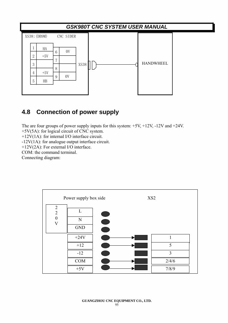
GSK980T CNC SYSTEM USER MANUAL
GUANGZHOU CNC EQUIPMENT CO., LTD. 95
1
2
3
4
5
6
7
8
9
+5V
0V+5V
HB
0V
XS38:(DB9M) CNC SIDER
XS38 HANDWHEEL
HA
4.8 Connection of power supply The are four groups of power supply inputs for this system: +5V, +12V, -12V and +24V. +5V(5A): for logical circuit of CNC system. +12V(1A): for internal I/O interface circuit. -12V(1A): for analogue output interface circuit. +12V(2A): For external I/O interface. COM: the command terminal. Connecting diagram:
Power supply box side
2 2 0 V
L
N
GND
+24V
+12
-12
COM
+5V
XS2
1
5
3
2/4/6
7/8/9
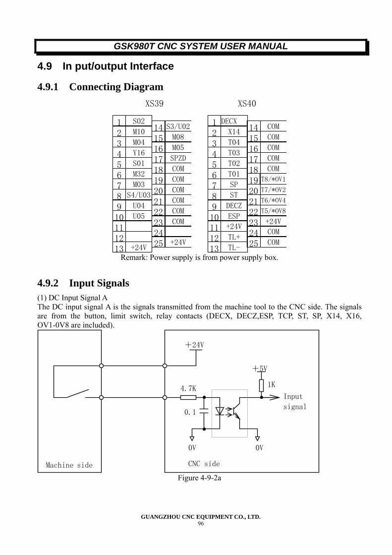
GSK980T CNC SYSTEM USER MANUAL
GUANGZHOU CNC EQUIPMENT CO., LTD. 96
4.9 In put/output Interface
4.9.1 Connecting Diagram
S021M102M043Y164S015M326M037
S4/U038U049U0510
1112
+24V13
S3/U0214M0815M0516SPZD17COM18COM19COM20COM21COM22COM23
24+24V25
XS39
DECX1X142T043T034T025T016SP7ST8DECZ9ESP10+24V11TL+12TL-13
COM14COM15COM16COM17COM18
T8/*OV119T7/*OV220T6/*OV421T5/*OV822+24V23COM24COM25
XS40
Remark: Power supply is from power supply box.
4.9.2 Input Signals (1) DC Input Signal A The DC input signal A is the signals transmitted from the machine tool to the CNC side. The signals are from the button, limit switch, relay contacts (DECX, DECZ,ESP, TCP, ST, SP, X14, X16, OV1-0V8 are included).
+24V
+5V
Machine side CNC side
0V
Input
signal
1K4.7K
0.1
0V
Figure 4-9-2a
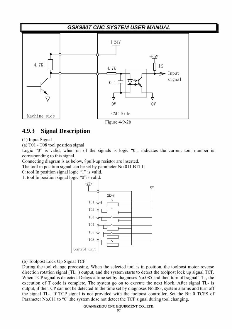
GSK980T CNC SYSTEM USER MANUAL
GUANGZHOU CNC EQUIPMENT CO., LTD. 97
+24V
+5V
Machine sideCNC Side
0V
Input
signal
1K4.7K
0.1
0V
4.7K
Figure 4-9-2b
4.9.3 Signal Description (1) Input Signal (a) T01~ T08 tool position signal Logic “0” is valid, when on of the signals is logic “0”, indicates the current tool number is corresponding to this signal. Connecting diagram is as below, 8pull-up resistor are inserted. The tool in position signal can be set by parameter No.011 B1T1: 0: tool In position signal logic “1” is valid. 1: tool In position signal logic “0”is valid.
+24V
T01
T02
T03
T04
T05
T08
Control unit
2K*8
0V
(b) Toolpost Lock Up Signal TCP During the tool change processing, When the selected tool is in position, the toolpost motor reverse direction rotation signal (TL+) output, and the system starts to detect the toolpost lock up signal TCP. When TCP signal is detected. Delays a time set by diagnoses No.085 and then turn off signal TL-, the execution of T code is complete, The system go on to execute the next block. After signal TL- is output, if the TCP can not be detected In the time set by diagnoses No.083, system alarms and turn off the signal TL-. If TCP signal is not provided with the toolpost controller, Set the Bit 0 TCPS of Parameter No.011 to “0”,the system dose not detect the TCP signal during tool changing.
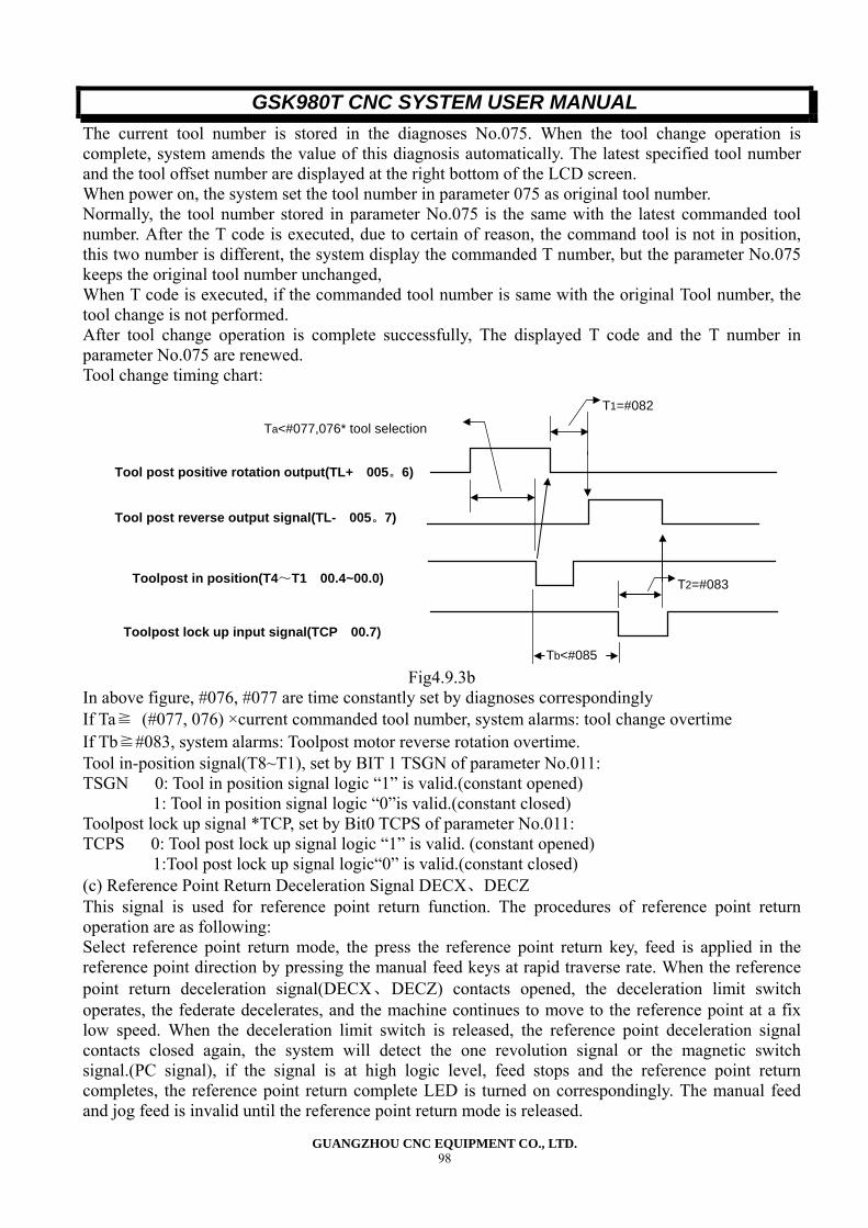
GSK980T CNC SYSTEM USER MANUAL
GUANGZHOU CNC EQUIPMENT CO., LTD. 98
The current tool number is stored in the diagnoses No.075. When the tool change operation is complete, system amends the value of this diagnosis automatically. The latest specified tool number and the tool offset number are displayed at the right bottom of the LCD screen. When power on, the system set the tool number in parameter 075 as original tool number. Normally, the tool number stored in parameter No.075 is the same with the latest commanded tool number. After the T code is executed, due to certain of reason, the command tool is not in position, this two number is different, the system display the commanded T number, but the parameter No.075 keeps the original tool number unchanged, When T code is executed, if the commanded tool number is same with the original Tool number, the tool change is not performed. After tool change operation is complete successfully, The displayed T code and the T number in parameter No.075 are renewed. Tool change timing chart:
Tool post positive rotation output(TL+ 005。6)
Toolpost lock up input signal(TCP 00.7)
Toolpost in position(T4~T1 00.4~00.0)
Tool post reverse output signal(TL- 005。7)
T1=#082
T2=#083
Tb<#085
Ta<#077,076* tool selection
Fig4.9.3b
In above figure, #076, #077 are time constantly set by diagnoses correspondingly If Ta≧ (#077, 076) ×current commanded tool number, system alarms: tool change overtime If Tb≧#083, system alarms: Toolpost motor reverse rotation overtime. Tool in-position signal(T8~T1), set by BIT 1 TSGN of parameter No.011: TSGN 0: Tool in position signal logic “1” is valid.(constant opened) 1: Tool in position signal logic “0”is valid.(constant closed) Toolpost lock up signal *TCP, set by Bit0 TCPS of parameter No.011: TCPS 0: Tool post lock up signal logic “1” is valid. (constant opened) 1:Tool post lock up signal logic“0” is valid.(constant closed) (c) Reference Point Return Deceleration Signal DECX、DECZ This signal is used for reference point return function. The procedures of reference point return operation are as following: Select reference point return mode, the press the reference point return key, feed is applied in the reference point direction by pressing the manual feed keys at rapid traverse rate. When the reference point return deceleration signal(DECX、DECZ) contacts opened, the deceleration limit switch operates, the federate decelerates, and the machine continues to move to the reference point at a fix low speed. When the deceleration limit switch is released, the reference point deceleration signal contacts closed again, the system will detect the one revolution signal or the magnetic switch signal.(PC signal), if the signal is at high logic level, feed stops and the reference point return completes, the reference point return complete LED is turned on correspondingly. The manual feed and jog feed is invalid until the reference point return mode is released.
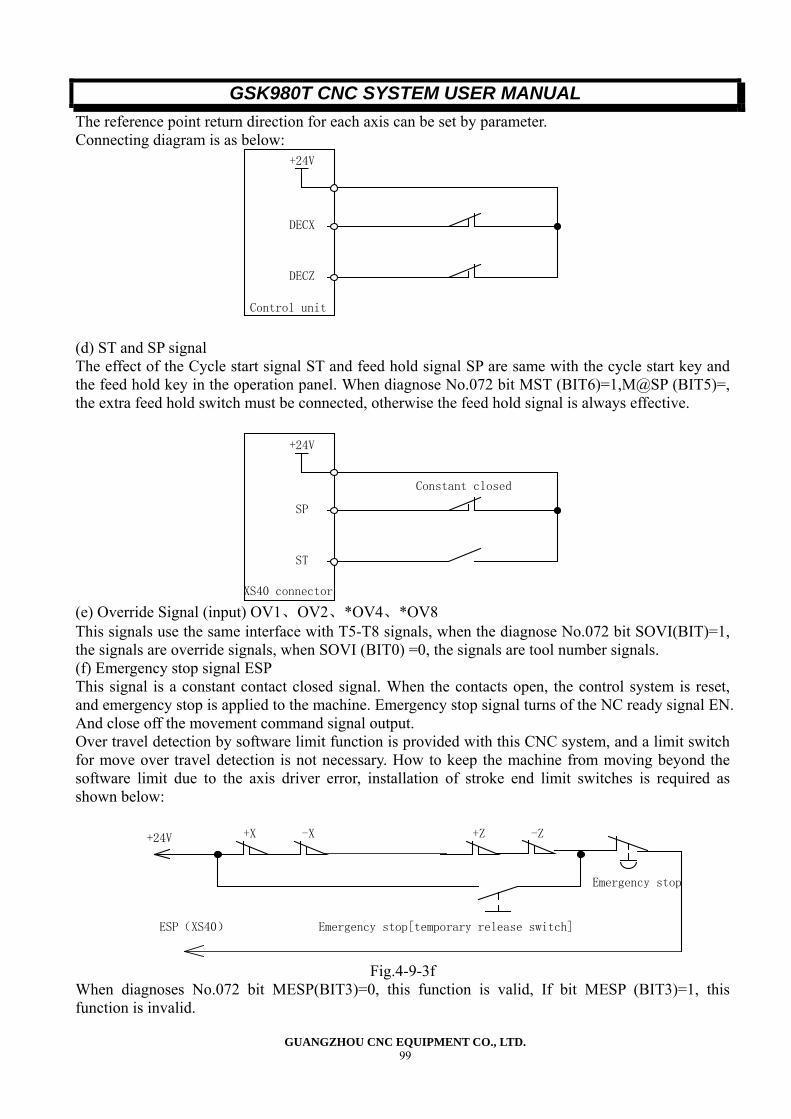
GSK980T CNC SYSTEM USER MANUAL
GUANGZHOU CNC EQUIPMENT CO., LTD. 99
The reference point return direction for each axis can be set by parameter. Connecting diagram is as below:
+24V
Control unit
DECX
DECZ
(d) ST and SP signal The effect of the Cycle start signal ST and feed hold signal SP are same with the cycle start key and the feed hold key in the operation panel. When diagnose No.072 bit MST (BIT6)=1,M@SP (BIT5)=, the extra feed hold switch must be connected, otherwise the feed hold signal is always effective.
+24V
XS40 connector
SP
ST
Constant closed
(e) Override Signal (input) OV1、OV2、*OV4、*OV8 This signals use the same interface with T5-T8 signals, when the diagnose No.072 bit SOVI(BIT)=1, the signals are override signals, when SOVI (BIT0) =0, the signals are tool number signals. (f) Emergency stop signal ESP This signal is a constant contact closed signal. When the contacts open, the control system is reset, and emergency stop is applied to the machine. Emergency stop signal turns of the NC ready signal EN. And close off the movement command signal output. Over travel detection by software limit function is provided with this CNC system, and a limit switch for move over travel detection is not necessary. How to keep the machine from moving beyond the software limit due to the axis driver error, installation of stroke end limit switches is required as shown below:
+X -X +Z -Z
Emergency stop[temporary release switch]
+24V
ESP(XS40)
Emergency stop
Fig.4-9-3f
When diagnoses No.072 bit MESP(BIT3)=0, this function is valid, If bit MESP (BIT3)=1, this function is invalid.
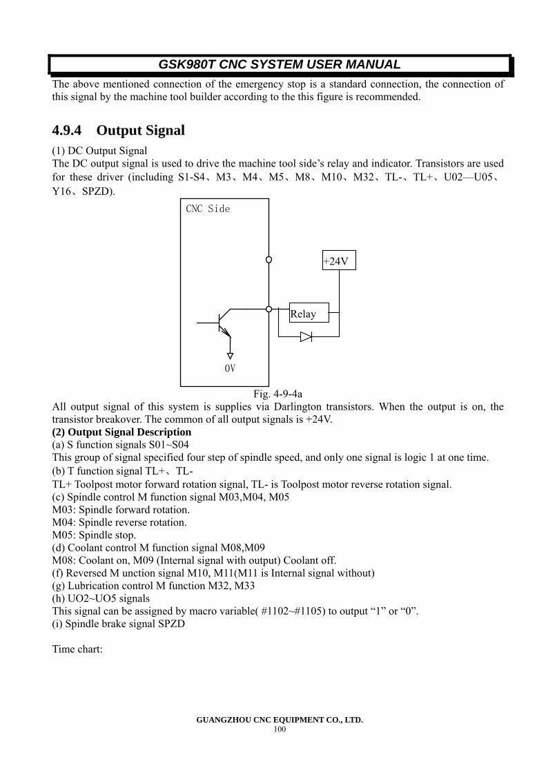
GSK980T CNC SYSTEM USER MANUAL
GUANGZHOU CNC EQUIPMENT CO., LTD. 100
The above mentioned connection of the emergency stop is a standard connection, the connection of this signal by the machine tool builder according to the this figure is recommended.
4.9.4 Output Signal (1) DC Output Signal The DC output signal is used to drive the machine tool side’s relay and indicator. Transistors are used for these driver (including S1-S4、M3、M4、M5、M8、M10、M32、TL-、TL+、U02—U05、Y16、SPZD).
CNC Side
0V
Relay
+24V
Fig. 4-9-4a
All output signal of this system is supplies via Darlington transistors. When the output is on, the transistor breakover. The common of all output signals is +24V. (2) Output Signal Description (a) S function signals S01~S04 This group of signal specified four step of spindle speed, and only one signal is logic 1 at one time. (b) T function signal TL+、TL- TL+ Toolpost motor forward rotation signal, TL- is Toolpost motor reverse rotation signal. (c) Spindle control M function signal M03,M04, M05 M03: Spindle forward rotation. M04: Spindle reverse rotation. M05: Spindle stop. (d) Coolant control M function signal M08,M09 M08: Coolant on, M09 (Internal signal with output) Coolant off. (f) Reversed M unction signal M10, M11(M11 is Internal signal without) (g) Lubrication control M function M32, M33 (h) UO2~UO5 signals This signal can be assigned by macro variable( #1102~#1105) to output “1” or “0”. (i) Spindle brake signal SPZD Time chart:
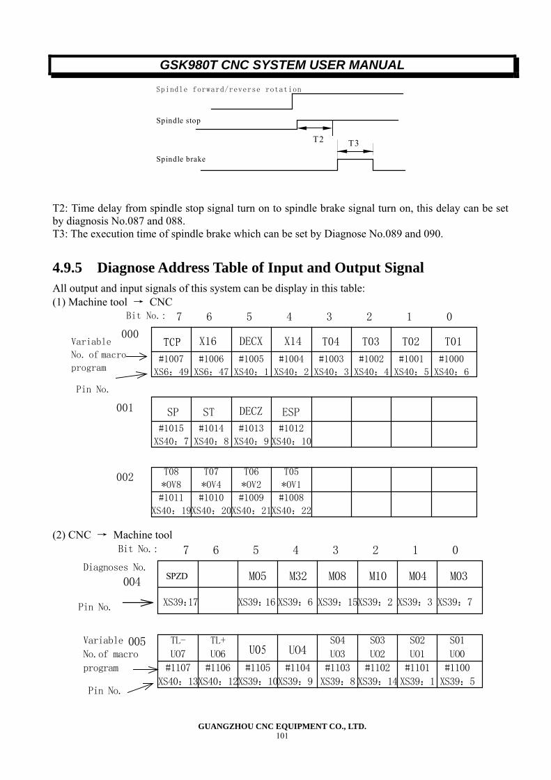
GSK980T CNC SYSTEM USER MANUAL
GUANGZHOU CNC EQUIPMENT CO., LTD. 101
Spindle brake
Spindle stop
Spindle forward/reverse rotation
T3T2
T2: Time delay from spindle stop signal turn on to spindle brake signal turn on, this delay can be set by diagnosis No.087 and 088. T3: The execution time of spindle brake which can be set by Diagnose No.089 and 090.
4.9.5 Diagnose Address Table of Input and Output Signal All output and input signals of this system can be display in this table: (1) Machine tool → CNC
DECZ
DECX T04 T03 T02 T01
ST ESP
Bit No.: 7 6 5 4 3 2 1 0
000
001
002
Pin No.
SP
TCP
T08
*OV8 T07
*OV4 T06
*OV2 T05
*OV1
#1007
XS6:49
#1005
XS40:1
#1003
XS40:3
#1015
XS40:7 #1014
XS40:8
#1008
XS40:22
#1009
XS40:21
#1010
XS40:20
#1011
XS40:19
#1013
XS40:9
#1012
XS40:10
#1002
XS40:4
#1001
XS40:5 #1000
XS40:6
#1004
XS40:2
#1006
XS6:47
X16 X14 Variable
No. of macro
program
(2) CNC → Machine tool
Diagnoses No.
Bit No.: 7 6 5 4 3 2 1 0
004
005
Pin No.
M03M04 M10M08M32
XS39:7XS39:3 XS39:2 XS39:15XS39:6XS39:17 XS39:16
M05 SPZD
UO5 UO4 TL-
UO7 TL+
UO6 S04
UO3 S03
UO2 S02
UO1 S01
UO0 #1107
XS40:13 #1106
XS40:12
#1105
XS39:10
#1104
XS39:9
#1103
XS39:8
#1102
XS39:14 #1101
XS39:1 #1100
XS39:5Pin No.
Variable
No.of macro
program
GSK980T CNC SYSTEM USER MANUAL
GUANGZHOU CNC EQUIPMENT CO., LTD. 102
V Adjustment of Machine
5.1 Preparation before Power On Be sure to connect the power supply, emergency stop button and the limit switch properly before turning on the power supply of the system.
5.2 Adjustment of Machine
5.2.1 Emergency Stop Button The emergency stop signal can be shielded by the setting of Bit3 of diagnosis No.072: MESP = 1, emergency stop is not effective (for adjustment of machine) MSEP = 0 emergency stop is effective.
5.2.2 Adjustment of Drive Axis (1) Driver Alarm If X axis or Z axis driver alarm occurs when power is turn on, Check if the driver alarm indicator is on. If the indicator is on, the driver unit is faulty, replace a good one. Check if the driver alarm signal is disconnected. If above trouble dose not occur, the alarm signal level is not correct. Reset Bit0 and Bit 1 of parameter No.009(ALAMZ and ALAMX are corresponding to Z and X axis respectively) After resetting, press Reset[∥] key to reset the alarm. (2)Rotating Direction Adjustment of Drive Motor If the rotation direction of a motor is reverse with the coordinate of the CNC system, change the rotation direction by changing the setting Biro or of parameter NO.008,the rotation direction also can be changed by the setting of the direction selection selecting switch of the driver unit. (3) Adjustment of Electric gear Expression CMR: Command multiply for X and Z axis. (Parameter Np.015~0160)
CMDCMR =
1000axL360×
CMD: Command denominator of each axis. (parameter No.017~018) a: Step angle (degree) L: Distance the machine tool moves per revolution of the axis motor (Unit: mm). For example: The Z axis stepping motor which with 0.6° step angle is connected with the ball lead screw directly, the pitch of the Z axis lead screw is 6mm. The X stepping motor with a step angle 0.75° is connected with the lead screw by a timing belt, the gear reduction ration is 3/5 and the pitch of the X axis lead
GSK980T CNC SYSTEM USER MANUAL
GUANGZHOU CNC EQUIPMENT CO., LTD. 103
screw is 4mm. Set the subdivision switch of the driver unit to 10, thus, the step angle of Z axis is 0.006 degree, the step angle of x axis is 0.075 degree. X axis electric gear calculating:
CMDCMR =
1000axL360×
A=0.75 L = 4 The least output unit of this system equates to CMD/CMR = 1/1 (unit: 0.001mm) Parameter No.015 and parameter No.017 are set to “1” X axis electric gear calculating: a = 0.75 L = 4
CMDCMR =
1000axL360×
The least output unit of this system equates to CMDZ/CMRZ = 1/1 (unit: 0.001mm). Parameter No.016 and parameter No.018 are set to “1” Note: No ever what kind of step angle the stepping motor have, the least command unit of the system is 0.001mm, the least output unit of the system is determined by a and L. (4) Rapid Travel Rate and Linear Acc/Dec Adjustment Parameter No.022 and Parameter No.023 are used to set the rapid travel rate of X axis and Z axis respectively. The setting range is from 0 to 7600mm/min (the setting range of X axis is halved). Parameter No.024 and No.025 are used to set the range of acceleration/deceleration (8-4000mm). For stepping motor, the value can be set a little bigger, such as 450. (5) Upper Limit of Cutting Feedrate Adjustment Parameter No.019 is used for setting the upper limit of cutting federate. This parameter must be set to 8000. (6) Thread Cutting Adjustment Adjustment of Width of Chamfering Parameter No.026 is used for setting the width of chamfering for thread cutting Adjustment of Acceleration/deceleration is Thread Cutting, the width of Chamfering = THDCH* 1/10* pitch. Parameter No.026 is used to for setting the Acc/Dec time constant value in thread cutting cycle. (7) Machine Zero Point Adjustment To confirm whether the zero point return deceleration limit switch is connected correctly or not, check Bit5 (DECX) and Bit5(DECZ) of diagnosis No.000. To confirm whether the zero point return signal is connected correctly or not, check Bit0 (PCX) and Bit (PCZ) of diagnosis No.008. If these signals are connected correctly, the corresponding Bit becomes“1” when one revolution signal is detected. (8) Backlash Compensation of lead screw Parameter No.034 and No.035 are used to set the Backlash compensation value of X and Z axis lead screw respectively.
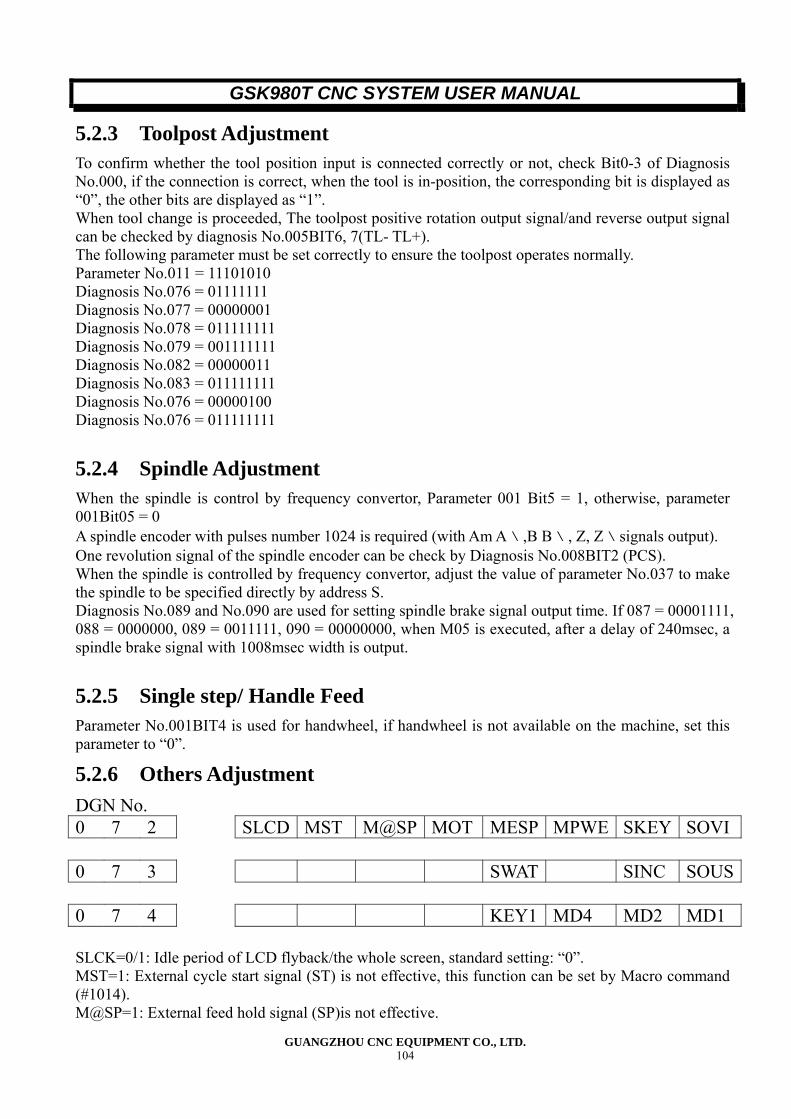
GSK980T CNC SYSTEM USER MANUAL
GUANGZHOU CNC EQUIPMENT CO., LTD. 104
5.2.3 Toolpost Adjustment To confirm whether the tool position input is connected correctly or not, check Bit0-3 of Diagnosis No.000, if the connection is correct, when the tool is in-position, the corresponding bit is displayed as “0”, the other bits are displayed as “1”. When tool change is proceeded, The toolpost positive rotation output signal/and reverse output signal can be checked by diagnosis No.005BIT6, 7(TL- TL+). The following parameter must be set correctly to ensure the toolpost operates normally. Parameter No.011 = 11101010 Diagnosis No.076 = 01111111 Diagnosis No.077 = 00000001 Diagnosis No.078 = 011111111 Diagnosis No.079 = 001111111 Diagnosis No.082 = 00000011 Diagnosis No.083 = 011111111 Diagnosis No.076 = 00000100 Diagnosis No.076 = 011111111
5.2.4 Spindle Adjustment When the spindle is control by frequency convertor, Parameter 001 Bit5 = 1, otherwise, parameter 001Bit05 = 0 A spindle encoder with pulses number 1024 is required (with Am A﹨,B B﹨, Z, Z﹨signals output). One revolution signal of the spindle encoder can be check by Diagnosis No.008BIT2 (PCS). When the spindle is controlled by frequency convertor, adjust the value of parameter No.037 to make the spindle to be specified directly by address S. Diagnosis No.089 and No.090 are used for setting spindle brake signal output time. If 087 = 00001111, 088 = 0000000, 089 = 0011111, 090 = 00000000, when M05 is executed, after a delay of 240msec, a spindle brake signal with 1008msec width is output.
5.2.5 Single step/ Handle Feed Parameter No.001BIT4 is used for handwheel, if handwheel is not available on the machine, set this parameter to “0”.
5.2.6 Others Adjustment DGN No. 0 7 2 SLCD MST M@SP MOT MESP MPWE SKEY SOVI 0 7 3 SWAT SINC SOUS 0 7 4 KEY1 MD4 MD2 MD1 SLCK=0/1: Idle period of LCD flyback/the whole screen, standard setting: “0”. MST=1: External cycle start signal (ST) is not effective, this function can be set by Macro command (#1014). M@SP=1: External feed hold signal (SP)is not effective.
GSK980T CNC SYSTEM USER MANUAL
GUANGZHOU CNC EQUIPMENT CO., LTD. 105
M@SP=0: External feed hold signal (SP0 is effective, in this case, external feed hold button must be combined, otherwise, alarm occurs. MOT=1 Disable software travel limit detecting function. MESP=1 Disable emergency stop signal (ESP). MPWE=1 Disable parameter switch. SKEY=1: Disable program switch. SOVI=1: T08-T05 as override switch. Swat=1: Waiting screen is display when turn on the power, press any key to change to the normal screen. SINC=1: Disable Step/handle amount 0.1 and 1 to avoid loss step. SOUS=1: S4-S1 signal setting. SANG=1: S4-S are # 1103#1100(macro define) SANG=0: SUOS=1: S4-S1 is output. SUOS=1: Only S2-S1 is output. KEY1=1: The program switch is set to “0”after power on.
5.3 Standard Parameter Setting and the Storage of Parameter,
Diagnosis and Program 1) Set the parameter switch to “on”, and turn off the power supply, the turn on the power while [N] and [I] key are depressing. The standard parameter is load automatically. (Refer to the Appendix I for the detail of standard parameter). The parameter should be set depend on the required of the user. Backup parameter for resuming. 2)When the machine adjustment is finished, select Program screen in Edit mode, Key in [N] and [I] and the press [STO] key, all parameter, diagnosis offset, and program are stored into N1 Section of the electric disk, using the same procedures, the data can save to N0, N2 section of electric disk, the electric disk can store the data without backup battery.
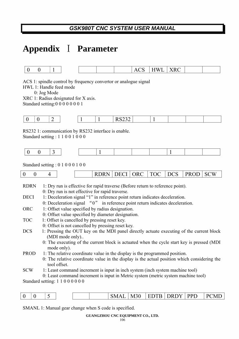
GSK980T CNC SYSTEM USER MANUAL
GUANGZHOU CNC EQUIPMENT CO., LTD. 106
Appendix Ⅰ Parameter
ACS 1: spindle control by frequency convertor or analogue signal HWL 1: Handle feed mode
0: Jog Mode XRC 1: Radius designated for X axis. Standard setting:0 0 0 0 0 0 0 1
RS232 1: communication by RS232 interface is enable. Standard setting : 1 1 0 0 1 0 0 0
Standard setting : 0 1 0 0 0 1 0 0
RDRN 1: Dry run is effective for rapid traverse (Before return to reference point).
0: Dry run is not effective for rapid traverse. DECI 1: Deceleration signal “1” in reference point return indicates deceleration.
0: Deceleration signal “0” in reference point return indicates deceleration. ORC 1: Offset value specified by radius designation.
0: Offset value specified by diameter designation. TOC 1: Offset is cancelled by pressing reset key.
0: Offset is not cancelled by pressing reset key. DCS 1: Pressing the OUT key on the MDI panel directly actuate executing of the current block
(MDI mode only).. 0: The executing of the current block is actuated when the cycle start key is pressed (MDI
mode only). PROD 1: The relative coordinate value in the display is the programmed position.
0: The relative coordinate value in the display is the actual position which considering the tool offset.
SCW 1: Least command increment is input in inch system (inch system machine tool) 0: Least command increment is input in Metric system (metric system machine tool)
Standard setting: 1 1 0 0 0 0 0 0
SMANL 1: Manual gear change when S code is specified.
0 0 1 ACS HWL XRC
0 0 2 1 1 RS232 1
0 0 3 1 1
0 0 4 RDRN DECI ORC TOC DCS PROD SCW
0 0 5 SMAL M30 EDTB DRDY PPD PCMD
GSK980T CNC SYSTEM USER MANUAL
GUANGZHOU CNC EQUIPMENT CO., LTD. 107
0: Auto gear change when S code is specified. M30 1: Return to the head of the program after executing M30 (B type).
0: Do not return to the head of the program until cycle start key is pressed (A type). EDTB 1: Editing and inserting operation A.
0: Editing and inserting operation B. DRDY 0: Driver/servo ready signal “0”indicates driver/ servo ready.
1: Driver/ servo ready signal “1” indicates driver/ servo ready. PPD 1: The relative coordinate value is preset when the absolute coordinate system is set by
G50. 0: The relative coordinate value is preset when the absolute coordinate system is set by
G50. PCMD 1: The waveform of output signal is peak pulse.
0: The waveform of output signal is square pulse. Standard setting: 0 0 0 1 0 0 0 1
PSG2, PSG1: Gear ration of spindle and spindle (position) encoder.
Magnification PSG2 PSG1 ×1 0 0 ×2 0 1 ×4 1 0 ×8 1 1
CM98 0: An alarm occurs when an unusable M, S, T code was commanded.
1: When an unusable M, S, T code is executed, the system will not alarm but call a subprogram correspondingly.
1.1: M code, when an unusable M code is executed, the corresponding subprogram will be call: MOO: Call subprogram No.90 O O/
1.2: S code, when S10~S99 is executed, the following subprogram will be call: S□□ : Call subprogram No.91□□ (When analogue spindle control signal is output, subprogram will not be call).
1.3: T code, when T10~T99 is executed, the following subprogram will be called. T△△: Call subprogram No.92△△.
OVRI = 0 (otherwise, the federate override is not correct) ZMX ZMZ: The reference point return direction and the backlash initial direction at power on for X
and Z axis. 1: Minus 0: Plus
Note: After the power is turn on , the backlash compensation is initial performed when the axis moves in the opposite direction against the direction, which is set by this parameter. Standard setting: 0 0 0 0 0 0 0 0
SMZ 0: Speed control at corner.
1: In deceleration, the control proceeds to the next block after the specified speed has
0 0 6 PSG2 PSG1 CM98 OVRI ZMZ ZMS
0 0 7 SMZ ZCZ ZCX
GSK980T CNC SYSTEM USER MANUAL
GUANGZHOU CNC EQUIPMENT CO., LTD. 108
become zero. ZCX, Z 0: It needs deceleration switch and zero point signal to perform reference point return
function. 1: Magnetic switch reference point return method (Reference point return mode C)
If the machine Zero point is set at the positive direction of the axis (Return to zero point from minus direction to positive direction), the parameter No.0006 ZMZ-ZMX must be set to “1”. If the machine Zero point is set at the positive direction of the axis (Return to zero point from positive direction to minus direction), the parameter No.0006 ZMZ-ZMX must be set to “0”. Standard setting: 0 0 0 0 1 0 0 0
DIRZ, DIRX: Rotating direction of X and Z axis motion. Standard setting: 0 0 0 0 0 0 1 1
RSJG 0: M03,M04, lubrication and coolant control output are cancelled by reset button.
1: M03,M04, lubrication and coolant control output are not cancelled by reset button. ALMZ 0:When the polarity of Z axis driver alarm signal is “1”indicates alarm.
1: When the polarity of Z axis driver alarm signal is “0”indicates alarm. ALMX 0: When the polarity of X axis driver alarm signal is “1” indicates alarm.
1: When the polarity of X axis driver alarm signal is “1” indicates alarm. Standard setting: 0 0 0 0 0 0 0 0
NOFC 1: Offset counter input is not effective.
0: Offset counter input is effective. CPF4,3,2,1 The pulse frequency of backlash compensation (for all axis).
Pulse frequency of backlash compensation = (setting value+1) Kpps. Standard setting: 0 0 0 0 0 0 0 1
BDEC 0: Backlash compensation mode A, The compensation is performed in a fixed pulse
frequency (Set by CPF4,3,2,1 and BD8).It means the federate for compensation is fixed. 1: Backlash compensation mode B, the compensation is performed with acceleration and
deceleration. BD8 0: The backlash compensation is performed at the frequency set by parameter No.010..
1: The backlash compensation is performed at 1/8 of the frequency set by parameter
0 0 8 DIRZ DIRX
0 0 9 RSJG ALMZ ALMX
0 1 0 NOFC CPF4 CPF3 CPF2 CPF1
0 1 1 BDEC BD8 RVDL ZDIL KSGN ANIK TSGN TCPS
Low speedzero return
Proximity switch Zero point
Rapid travel
GSK980T CNC SYSTEM USER MANUAL
GUANGZHOU CNC EQUIPMENT CO., LTD. 109
No.010. RVDL 0: When the movement direction of axis is change, the direction signal will be output with
the feed pulse at the same time. 1: When the movement direction of axis is change, the direction signal will output first, and
the feed pulse will be output after a delay. ZDIL 0: When the spindle brake signal is output, axis interlock.
1: When the spindle brake signal is output, axis interlock is not effective. KSGN 0: When the axis moves at minus direction, the sign of movement is change.
1: When the axis moves at minus direction, the sign of movement is not change. ZNLK 0: In zero point return, the movement of the axis will stop once the corresponding direction
key is released. 1: In zero point return, once the corresponding key is pressed, the axis keep moving until
zero point return complete. To halt the movement, press [ZRN] key or [∥] key. TSGN 0: Toolpost in position signal “1”is effective.
1: Toolpost in position signal “0”is effective. TCPS 0: Toolpost lock up signal “0”is effective.
1: Toolpost lock up signal “1” is effective. (constant opened) Standard setting: 1 1 1 0 1 0 1 0 Note; To finish the setting of parameter CPF4,3,2,1, BD8, turn on the power supply after inputting the value.
APRS 1: Automatic coordinate system setting is conducted when reference point return is
performed. 0: Automatic coordinate system setting is not conducted.
WSFT 1: The workpiece coordinate system shifting is effective, and number of shifting is 0 or 100 0: The workpiece coordinate system shifting is not effective.
DOFSI 1: the direct measured value input for tool offset is effective. 0: The direct measured value input for tool offset is not effective.
PR69 1: The macro(sub) program(program number>9000) are protected from display and edit. 0: Display and edit of program enable.
Eel 1: When alarm occurs, can be edited. FFVY 1: driver alarm is not actuated when PRDY signal is on before MRDY is output.
0: driver alarm is actuated when PRDY signal is on before MRDY is output. EBCL 1: The EOB code is indicated by ;(semicolon) is the display of program.
0: The EOB code is indicated by *(asterisk) in the display of program. ISOT 1: Rapid traverse is effective even when reference point return is not conducted after
turning on the power. Standard setting: 0 0 1 0 1 1 1 1
PRGB 0: Program display mode A.
1: Program display mode B. In non-edit mode, the program is displayed when [PRG] button is pressed, by pressing the [CHG] button, the program the screen can be switched between the following two ways:
Program display only. The absolute and relative position is displayed on the upper part of the screen and the program displayed on the low part.
0 1 2 APRS WSFT DOFSI PR69 EAL OFVY EBCL ISOT
0 1 3 PEGB POD SBKM SKPF PODI PML3 PML2 PML1
GSK980T CNC SYSTEM USER MANUAL
GUANGZHOU CNC EQUIPMENT CO., LTD. 110
POD 0: Value input with or without decimal point is at will. 1: An alarm occurs when an address, which can be used with a decimal point, is specified
without decimal point. Alarm No.007: Decimal point input error or without decimal point input. SBKM 1: One block program can be executed in macro command executing .
0: One block program can not be executed in macro command executing PODI 1: The decimal point is added automatically.
0: The decimal point is not added automatically. Standard setting: 1 0 1 0 1 0 0 0
ZRSZ 1: Reference point is exist in Z axis (reference point return mode B)
0: Reference point is not exist in Z axis (reference point return mode A) ZRSX 1: Reference point is exist in X axis in X axis (reference point return mode B)
0: Reference point is not exist in X axis in X axis (reference point return mode A) Standard setting: 0 0 1 1 0 0 1 1
Standard setting: 1(related to gear ration , the pitch of lead screw and pulse equivalent)
CMRX CMRZ: Command multiply for X and Z axis. Setting range: 1~127 Standard setting:1 (related to gear ratio, the pitch of lead screw and pulse equivalent)
Standard setting: 1(related to gear ration, the pitch of lead screw and pulse equivalent)
CMDX,CMDZ: Command denominator of each axis. Setting range: 1~127 Standard setting : 1( related to gear ratio, the pitch of lead screw and pulse equivalent)
THDCH: Width of chamfering for thread cutting cycle (G92)/ Width= THDCH *1/10 *pitch Standard setting: 5
WLDTME: time width of Signal filter. Standard setting:2 When the power supply is turn on, the system check this parameter automatically, is the value is greater than 15, it will be set to “2”.
Standard setting :625
0 1 4 1I 1 ZRSZ ZRSX
0 1 5 CMRX
0 1 6 CMRZ
0 1 7 CMDX
0 1 8 CMDZ
0 1 9 THDCH
0 2 0 WLKTME
0 2 1 Analogue spindle control related data
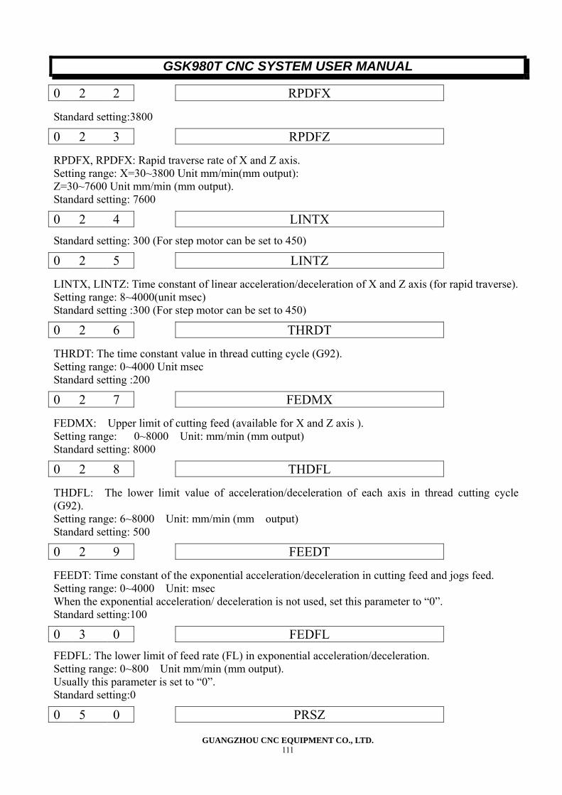
GSK980T CNC SYSTEM USER MANUAL
GUANGZHOU CNC EQUIPMENT CO., LTD. 111
Standard setting:3800
RPDFX, RPDFX: Rapid traverse rate of X and Z axis. Setting range: X=30~3800 Unit mm/min(mm output): Z=30~7600 Unit mm/min (mm output). Standard setting: 7600
Standard setting: 300 (For step motor can be set to 450)
LINTX, LINTZ: Time constant of linear acceleration/deceleration of X and Z axis (for rapid traverse). Setting range: 8~4000(unit msec) Standard setting :300 (For step motor can be set to 450)
THRDT: The time constant value in thread cutting cycle (G92). Setting range: 0~4000 Unit msec Standard setting :200
FEDMX: Upper limit of cutting feed (available for X and Z axis ). Setting range: 0~8000 Unit: mm/min (mm output) Standard setting: 8000
THDFL: The lower limit value of acceleration/deceleration of each axis in thread cutting cycle (G92). Setting range: 6~8000 Unit: mm/min (mm output) Standard setting: 500
FEEDT: Time constant of the exponential acceleration/deceleration in cutting feed and jogs feed. Setting range: 0~4000 Unit: msec When the exponential acceleration/ deceleration is not used, set this parameter to “0”. Standard setting:100
FEDFL: The lower limit of feed rate (FL) in exponential acceleration/deceleration. Setting range: 0~800 Unit mm/min (mm output). Usually this parameter is set to “0”. Standard setting:0
0 2 2 RPDFX
0 2 3 RPDFZ
0 2 4 LINTX
0 2 5 LINTZ
0 2 6 THRDT
0 2 7 FEDMX
0 2 8 THDFL
0 2 9 FEEDT
0 3 0 FEDFL
0 5 0 PRSZ
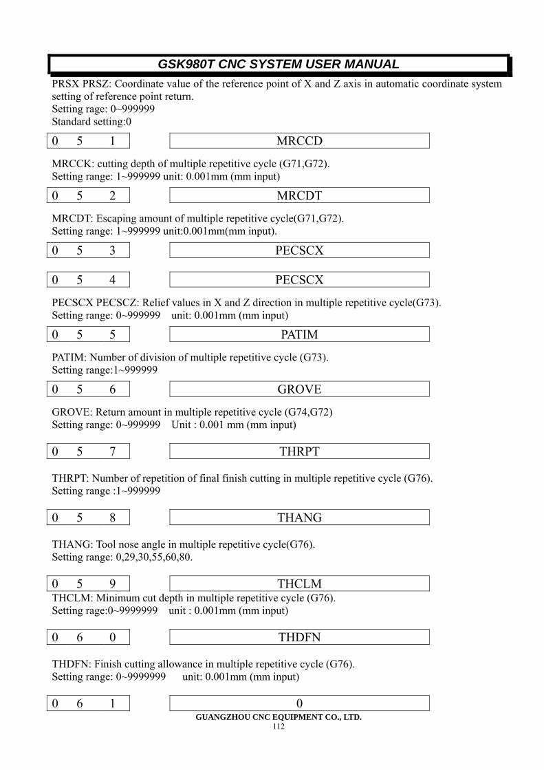
GSK980T CNC SYSTEM USER MANUAL
GUANGZHOU CNC EQUIPMENT CO., LTD. 112
PRSX PRSZ: Coordinate value of the reference point of X and Z axis in automatic coordinate system setting of reference point return. Setting rage: 0~999999 Standard setting:0
MRCCK: cutting depth of multiple repetitive cycle (G71,G72). Setting range: 1~999999 unit: 0.001mm (mm input)
MRCDT: Escaping amount of multiple repetitive cycle(G71,G72). Setting range: 1~999999 unit:0.001mm(mm input).
PECSCX PECSCZ: Relief values in X and Z direction in multiple repetitive cycle(G73). Setting range: 0~999999 unit: 0.001mm (mm input)
PATIM: Number of division of multiple repetitive cycle (G73). Setting range:1~999999
GROVE: Return amount in multiple repetitive cycle (G74,G72) Setting range: 0~999999 Unit : 0.001 mm (mm input) 0 5 7 THRPT THRPT: Number of repetition of final finish cutting in multiple repetitive cycle (G76). Setting range :1~999999 0 5 8 THANG THANG: Tool nose angle in multiple repetitive cycle(G76). Setting range: 0,29,30,55,60,80. 0 5 9 THCLM THCLM: Minimum cut depth in multiple repetitive cycle (G76). Setting rage:0~9999999 unit : 0.001mm (mm input) 0 6 0 THDFN THDFN: Finish cutting allowance in multiple repetitive cycle (G76). Setting range: 0~9999999 unit: 0.001mm (mm input) 0 6 1 0
0 5 1 MRCCD
0 5 2 MRCDT
0 5 3 PECSCX
0 5 4 PECSCX
0 5 5 PATIM
0 5 6 GROVE

GSK980T CNC SYSTEM USER MANUAL
GUANGZHOU CNC EQUIPMENT CO., LTD. 113
0 6 2 0 0 6 3 8000 0 6 4 0 0 6 5 1 0 6 6 1 Parameter No.061-066 are system parameters, don’t amend them to your liking.
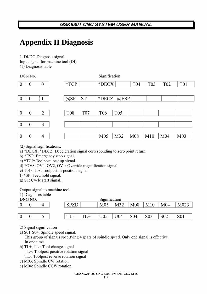
GSK980T CNC SYSTEM USER MANUAL
GUANGZHOU CNC EQUIPMENT CO., LTD. 114
Appendix II Diagnosis
1. DI/DO Diagnosis signal Input signal for machine tool (DI) (1) Diagnosis table DGN No. Signification
0 0 3 0 0 4 M05 M32 M08 M10 M04 M03 (2) Signal significations. a) *DECX, *DECZ: Deceleration signal corresponding to zero point return. b) *ESP: Emergency stop signal. c) *TCP: Toolpost lock up signal. d) *OV8, OV4, OV2, OV1: Override magnification signal. e) T01~ T08: Toolpost in-position signal f) *SP: Feed hold signal. g) ST: Cycle start signal. Output signal to machine tool: 1) Diagnoses table DNG NO. Signification 0 0 4 SPZD M05 M32 M08 M10 M04 M023 0 0 5 TL- TL+ U05 U04 S04 S03 S02 S01 2) Signal signification a) S01~S04: Spindle speed signal.
This group of signals specifying 4 gears of spindle speed. Only one signal is effective In one time.
b) TL+, TL-: Tool change signal TL+: Toolpost positive rotation signal TL-: Toolpost reverse rotation signal
c) M03: Spindle CW rotation e) M04: Spindle CCW rotation.
0 0 0 *TCP *DECX T04 T03 T02 T01
0 0 1 @SP ST *DECZ @ESP
0 0 2 T08 T07 T06 T05
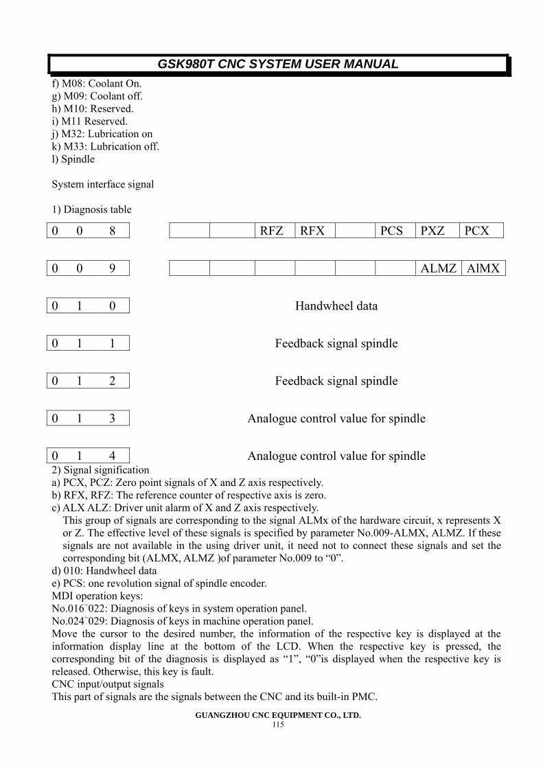
GSK980T CNC SYSTEM USER MANUAL
GUANGZHOU CNC EQUIPMENT CO., LTD. 115
f) M08: Coolant On. g) M09: Coolant off. h) M10: Reserved. i) M11 Reserved. j) M32: Lubrication on k) M33: Lubrication off. l) Spindle System interface signal 1) Diagnosis table
2) Signal signification a) PCX, PCZ: Zero point signals of X and Z axis respectively. b) RFX, RFZ: The reference counter of respective axis is zero. c) ALX ALZ: Driver unit alarm of X and Z axis respectively.
This group of signals are corresponding to the signal ALMx of the hardware circuit, x represents X or Z. The effective level of these signals is specified by parameter No.009-ALMX, ALMZ. If these signals are not available in the using driver unit, it need not to connect these signals and set the corresponding bit (ALMX, ALMZ )of parameter No.009 to “0”.
d) 010: Handwheel data e) PCS: one revolution signal of spindle encoder. MDI operation keys: No.016~022: Diagnosis of keys in system operation panel. No.024~029: Diagnosis of keys in machine operation panel. Move the cursor to the desired number, the information of the respective key is displayed at the information display line at the bottom of the LCD. When the respective key is pressed, the corresponding bit of the diagnosis is displayed as “1”, “0”is displayed when the respective key is released. Otherwise, this key is fault. CNC input/output signals This part of signals are the signals between the CNC and its built-in PMC.
0 0 8 RFZ RFX PCS PXZ PCX
0 0 9 ALMZ AlMX
0 1 0 Handwheel data
0 1 1 Feedback signal spindle
0 1 2 Feedback signal spindle
0 1 3 Analogue control value for spindle
0 1 4 Analogue control value for spindle
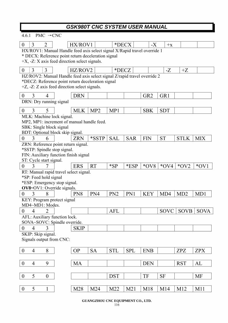
GSK980T CNC SYSTEM USER MANUAL
GUANGZHOU CNC EQUIPMENT CO., LTD. 116
4.6.1 PMC →CNC
HX/ROV1: Manual Handle feed axis select signal X/Rapid travel override 1 * DECX: Reference point return deceleration signal +X, -Z: X axis feed direction select signals.
HZ/ROV2: Manual Handle feed axis select signal Z/rapid travel override 2 *DECZ: Reference point return deceleration signal +Z, -Z: Z axis feed direction select signals.
DRN: Dry running signal
MLK: Machine lock signal. MP2, MP1: increment of manual handle feed. SBK: Single block signal BDT: Optional block skip signal. 0 3 6 ZRN *SSTP SAL SAR FIN ST STLK MIX ZRN: Reference point return signal. *SSTP: Spindle stop signal. FIN: Auxiliary function finish signal ST: Cycle start signal. 0 3 7 ERS RT *SP *ESP *OV8 *OV4 *OV2 *OV1RT: Manual rapid travel select signal. *SP: Feed hold signal *ESP: Emergency stop signal. OV8~OV1: Override signals. 0 3 8 PN8 PN4 PN2 PN1 KEY MD4 MD2 MD1 KEY: Program protect signal MD4~MD1: Modes. 0 4 2 AFL SOVC SOVB SOVAAFL: Auxiliary function lock. SOVA~SOVC: Spindle override. 0 4 3 SKIP SKIP: Skip signal. Signals output from CNC: 0 4 8 OP SA STL SPL ENB ZPZ ZPX 0 4 9 MA DEN RST AL 0 5 0 DST TF SF MF 0 5 1 M28 M24 M22 M21 M18 M14 M12 M11
0 3 2 HX/ROV1 *DECX -X +x
0 3 3 HZ/ROV2 *DECZ -Z +Z
0 3 4 DRN GR2 GR1
0 3 5 MLK MP2 MP1 SBK SDT
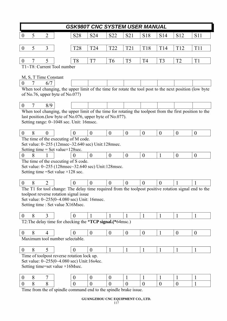
GSK980T CNC SYSTEM USER MANUAL
GUANGZHOU CNC EQUIPMENT CO., LTD. 117
0 5 2 S28 S24 S22 S21 S18 S14 S12 S11 0 5 3 T28 T24 T22 T21 T18 T14 T12 T11 0 7 5 T8 T7 T6 T5 T4 T3 T2 T1 T1~T8: Current Tool number M, S, T Time Constant 0 7 6/7 When tool changing, the upper limit of the time for rotate the tool post to the next position (low byte of No.76, upper byte of No.077) 0 7 8/9 When tool changing, the upper limit of the time for rotating the toolpost from the first position to the last position.(low byte of No.076, upper byte of No.077). Setting range: 0~1048 sec. Unit: 16msec. 0 8 0 0 0 0 0 0 0 0 0 The time of the executing of M code. Set value: 0~255 (12msec~32.640 sec) Unit:128msec. Setting time = Set value×128sec. 0 8 1 0 0 0 0 0 1 0 0 The time of the executing of S code. Set value: 0~255 (128msec~32.640 sec) Unit:128msec. Setting time =Set value ×128 sec. 0 8 2 0 0 0 0 0 0 1 1 The T1 for tool change: The delay time required from the toolpost positive rotation signal end to the toolpost reverse rotation signal issue Set value: 0~255(0~4.080 sec) Unit: 16msec. Setting time : Set value X16Msec. 0 8 3 0 1 1 1 1 1 1 1 T2:The delay time for checking the *TCP signal.(*64msc.) 0 8 4 0 0 0 0 0 1 0 0 Maximum tool number selectable. 0 8 5 0 0 1 1 1 1 1 1 Time of toolpost reverse rotation lock up. Set value: 0~255(0~4.080 sec) Unit:16s4ec. Setting time=set value ×16Msec. 0 8 7 0 0 0 1 1 1 1 1 0 8 8 0 0 0 0 0 0 0 1 Time from the of spindle command end to the spindle brake issue.
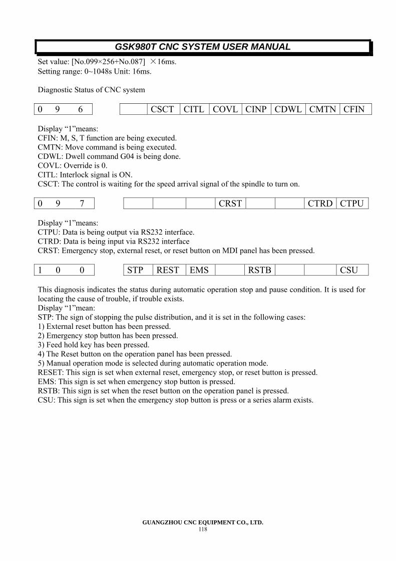
GSK980T CNC SYSTEM USER MANUAL
GUANGZHOU CNC EQUIPMENT CO., LTD. 118
Set value: [No.099×256+No.087] ×16ms. Setting range: 0~1048s Unit: 16ms. Diagnostic Status of CNC system 0 9 6 CSCT CITL COVL CINP CDWL CMTN CFIN Display “1”means: CFIN: M, S, T function are being executed. CMTN: Move command is being executed. CDWL: Dwell command G04 is being done. COVL: Override is 0. CITL: Interlock signal is ON. CSCT: The control is waiting for the speed arrival signal of the spindle to turn on. 0 9 7 CRST CTRD CTPU Display “1”means: CTPU: Data is being output via RS232 interface. CTRD: Data is being input via RS232 interface CRST: Emergency stop, external reset, or reset button on MDI panel has been pressed. 1 0 0 STP REST EMS RSTB CSU This diagnosis indicates the status during automatic operation stop and pause condition. It is used for locating the cause of trouble, if trouble exists. Display “1”mean: STP: The sign of stopping the pulse distribution, and it is set in the following cases: 1) External reset button has been pressed. 2) Emergency stop button has been pressed. 3) Feed hold key has been pressed. 4) The Reset button on the operation panel has been pressed. 5) Manual operation mode is selected during automatic operation mode. RESET: This sign is set when external reset, emergency stop, or reset button is pressed. EMS: This sign is set when emergency stop button is pressed. RSTB: This sign is set when the reset button on the operation panel is pressed. CSU: This sign is set when the emergency stop button is press or a series alarm exists.
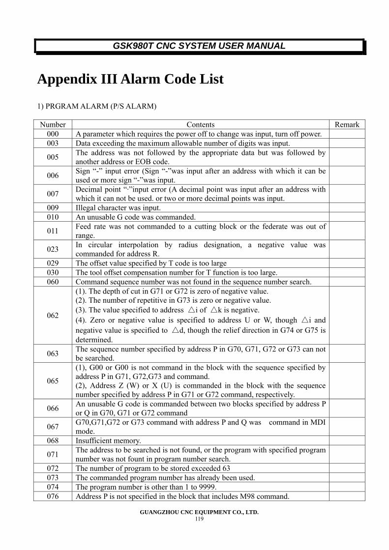
GSK980T CNC SYSTEM USER MANUAL
GUANGZHOU CNC EQUIPMENT CO., LTD. 119
Appendix III Alarm Code List
1) PRGRAM ALARM (P/S ALARM) Number Contents Remark
000 A parameter which requires the power off to change was input, turn off power. 003 Data exceeding the maximum allowable number of digits was input.
005 The address was not followed by the appropriate data but was followed by another address or EOB code.
006 Sign “-” input error (Sign “-”was input after an address with which it can be used or more sign “-”was input.
007 Decimal point “·”input error (A decimal point was input after an address with which it can not be used. or two or more decimal points was input.
009 Illegal character was input. 010 An unusable G code was commanded.
011 Feed rate was not commanded to a cutting block or the federate was out of range.
023 In circular interpolation by radius designation, a negative value was commanded for address R.
029 The offset value specified by T code is too large 030 The tool offset compensation number for T function is too large. 060 Command sequence number was not found in the sequence number search.
062
(1). The depth of cut in G71 or G72 is zero of negative value. (2). The number of repetitive in G73 is zero or negative value. (3). The value specified to address △i of △k is negative. (4). Zero or negative value is specified to address U or W, though △i and negative value is specified to △d, though the relief direction in G74 or G75 is determined.
063 The sequence number specified by address P in G70, G71, G72 or G73 can not be searched.
065
(1), G00 or G00 is not command in the block with the sequence specified by address P in G71, G72,G73 and command. (2), Address Z (W) or X (U) is commanded in the block with the sequence number specified by address P in G71 or G72 command, respectively.
066 An unusable G code is commanded between two blocks specified by address P or Q in G70, G71 or G72 command
067 G70,G71,G72 or G73 command with address P and Q was command in MDI mode.
068 Insufficient memory.
071 The address to be searched is not found, or the program with specified program number was not fount in program number search.
072 The number of program to be stored exceeded 63 073 The commanded program number has already been used. 074 The program number is other than 1 to 9999. 076 Address P is not specified in the block that includes M98 command.
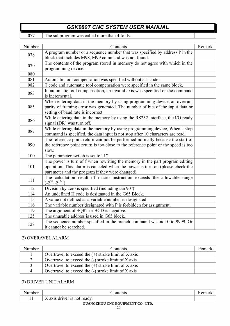
GSK980T CNC SYSTEM USER MANUAL
GUANGZHOU CNC EQUIPMENT CO., LTD. 120
077 The subprogram was called more than 4 folds.
Number Contents Remark
078 A program number or a sequence number that was specified by address P in the block that includes M98, M99 command was not found.
079 The contents of the program stored in memory do not agree with which in the programming device.
080 081 Automatic tool compensation was specified without a T code. 082 T code and automatic tool compensation were specified in the same block.
083 In automatic tool compensation, an invalid axis was specified or the command is incremental.
085 When entering data in the memory by using programming device, an overrun, parity of framing error was generated. The number of bits of the input data or setting of baud rate is incorrect.
086 While entering data in the memory by using the RS232 interface, the I/O ready signal (DR) was turn off.
087 While entering data in the memory by using programming device, When a stop command is specified, the data input is not stop after 10 characters are read.
090 The reference point return can not be performed normally because the start of the reference point return is too close to the reference point or the speed is too slow.
100 The parameter switch is set to “1”.
101 The power is turn of f when rewriting the memory in the part program editing operation. This alarm is canceled when the power is turn on (please check the parameter and the program if they were changed).
111 The calculation result of macro instruction exceeds the allowable range (-232~232-1)
112 Division by zero is specified (including tan 90°) 114 An undefined H code is designated in the G65 Block. 115 A value not defined as a variable number is designated 116 The variable number designated with P is forbidden for assignment. 119 The argument of SQRT or BCD is negative. 125 The unusable address is used in G65 block.
128 The sequence number specified in the branch command was not 0 to 9999. Or it cannot be searched.
2) OVERAVEL ALARM Number Contents Pemark
1 Overtravel to exceed the (+) stroke limit of X axis 2 Overtravel to exceed the (-) stroke limit of X axis 3 Overtravel to exceed the (+) stroke limit of X axis 4 Overtravel to exceed the (-) stroke limit of X axis
3) DRIVER UNIT ALARM Number Contents Remark
11 X axis driver is not ready.
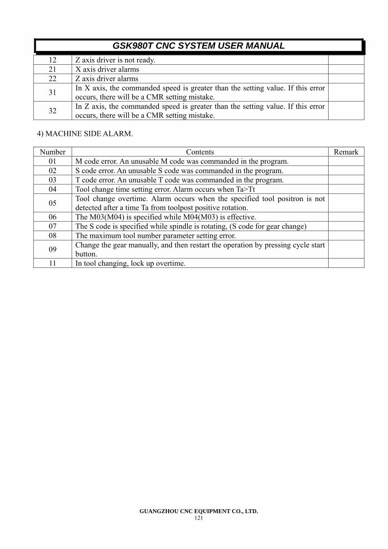
GSK980T CNC SYSTEM USER MANUAL
GUANGZHOU CNC EQUIPMENT CO., LTD. 121
12 Z axis driver is not ready. 21 X axis driver alarms 22 Z axis driver alarms
31 In X axis, the commanded speed is greater than the setting value. If this error occurs, there will be a CMR setting mistake.
32 In Z axis, the commanded speed is greater than the setting value. If this error occurs, there will be a CMR setting mistake.
4) MACHINE SIDE ALARM. Number Contents Remark
01 M code error. An unusable M code was commanded in the program. 02 S code error. An unusable S code was commanded in the program. 03 T code error. An unusable T code was commanded in the program. 04 Tool change time setting error. Alarm occurs when Ta>Tt
05 Tool change overtime. Alarm occurs when the specified tool positron is not detected after a time Ta from toolpost positive rotation.
06 The M03(M04) is specified while M04(M03) is effective. 07 The S code is specified while spindle is rotating, (S code for gear change) 08 The maximum tool number parameter setting error.
09 Change the gear manually, and then restart the operation by pressing cycle start button.
11 In tool changing, lock up overtime.
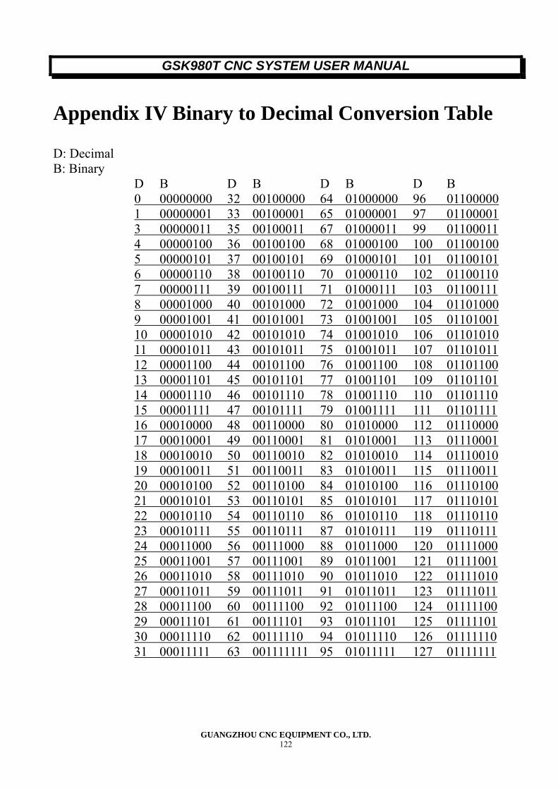
GSK980T CNC SYSTEM USER MANUAL
GUANGZHOU CNC EQUIPMENT CO., LTD. 122
Appendix IV Binary to Decimal Conversion Table
D: Decimal B: Binary
D B D B D B D B 0 00000000 32 00100000 64 01000000 96 01100000 1 00000001 33 00100001 65 01000001 97 01100001 3 00000011 35 00100011 67 01000011 99 01100011 4 00000100 36 00100100 68 01000100 100 01100100 5 00000101 37 00100101 69 01000101 101 01100101 6 00000110 38 00100110 70 01000110 102 01100110 7 00000111 39 00100111 71 01000111 103 01100111 8 00001000 40 00101000 72 01001000 104 01101000 9 00001001 41 00101001 73 01001001 105 01101001 10 00001010 42 00101010 74 01001010 106 01101010 11 00001011 43 00101011 75 01001011 107 01101011 12 00001100 44 00101100 76 01001100 108 01101100 13 00001101 45 00101101 77 01001101 109 01101101 14 00001110 46 00101110 78 01001110 110 01101110 15 00001111 47 00101111 79 01001111 111 01101111 16 00010000 48 00110000 80 01010000 112 01110000 17 00010001 49 00110001 81 01010001 113 01110001 18 00010010 50 00110010 82 01010010 114 01110010 19 00010011 51 00110011 83 01010011 115 01110011 20 00010100 52 00110100 84 01010100 116 01110100 21 00010101 53 00110101 85 01010101 117 01110101 22 00010110 54 00110110 86 01010110 118 01110110 23 00010111 55 00110111 87 01010111 119 01110111 24 00011000 56 00111000 88 01011000 120 01111000 25 00011001 57 00111001 89 01011001 121 01111001 26 00011010 58 00111010 90 01011010 122 01111010 27 00011011 59 00111011 91 01011011 123 01111011 28 00011100 60 00111100 92 01011100 124 01111100 29 00011101 61 00111101 93 01011101 125 01111101 30 00011110 62 00111110 94 01011110 126 01111110 31 00011111 63 001111111 95 01011111 127 01111111
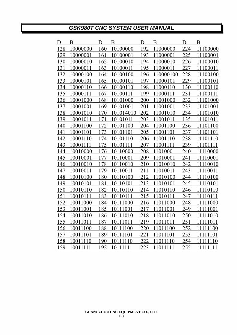
GSK980T CNC SYSTEM USER MANUAL
GUANGZHOU CNC EQUIPMENT CO., LTD. 123
D B D B D B D B 128 10000000 160 10100000 192 11000000 224 11100000 129 10000001 161 10100001 193 11000001 225 11100001 130 10000010 162 10100010 194 11000010 226 11100010 131 10000011 163 10100011 195 11000011 227 11100011 132 10000100 164 10100100 196 110000100 228 11100100 133 10000101 165 10100101 197 11000101 229 11100101 134 10000110 166 10100110 198 11000110 130 11100110 135 10000111 167 10100111 199 11000111 231 11100111 136 10001000 168 10101000 200 11001000 232 11101000 137 10001001 169 10101001 201 11001001 233 11101001 138 10001010 170 101014010 202 11001010 234 11101010 139 10001011 171 10101011 203 11001011 135 11101011 140 10001100 172 10101100 204 11001100 236 11101100 141 10001101 173 10101101 205 11001101 237 11101101 142 10001110 174 10101110 206 11001110 238 11101110 143 10001111 175 10101111 207 11001111 239 11101111 144 10010000 176 10110000 208 1101000 240 11110000 145 10010001 177 10110001 209 11010001 241 11110001 146 10010010 178 10110010 210 11010010 242 11110010 147 10010011 179 10110011 211 11010011 243 11110011 148 10010100 180 10110100 212 11010100 244 11110100 149 10010101 181 10110101 213 11010101 245 11110101 150 10010110 182 10110110 214 11010110 246 11110110 151 10010111 183 10110111 215 11010111 247 11110111 152 10011000 184 10111000 216 11011000 248 11111000 153 10011001 185 10111001 217 11011001 249 11111001 154 10011010 186 10111010 218 11011010 250 11111010 155 10011011 187 10111011 219 11011011 251 11111011 156 10011100 188 10111100 220 11011100 252 11111100 157 10011101 189 10111101 221 11011101 253 11111101 158 10011110 190 10111110 222 11011110 254 11111110 159 10011111 192 10111111 223 11011111 255 11111111
GSK980T CNC SYSTEM OPERATION MANUAL
GUANGZHOU CNC EQUIPMENT CO., LTD. I
Appendix V Installation dimension
● The installation dimension chart of GSK980T-L
980T
MST
φ63 r
eserve
d ha
ndwh
eel(
MPG)
6-φ
16
rese
rved ho
le
GSK980T CNC SYSTEM OPERATION MANUAL
GUANGZHOU CNC EQUIPMENT CO., LTD. II
●The installation dimension chart of GSK980T-B 980T
MST
GSK980T-B CNC system contour and installation dimension
4-φ7 EQS
φ63
reser
ved
handwh
eel(
MPG)
6-φ
16 reserved hole
GSK980T CNC SYSTEM OPERATION MANUAL
GUANGZHOU CNC EQUIPMENT CO., LTD. III
● The dimension chart of GSK980TA
MST
GSK980T CNC SYSTEM OPERATION MANUAL
GUANGZHOU CNC EQUIPMENT CO., LTD. IV
● The dimension chart of GSK980TA-L
Fig.6.GSK980TA+AP01 CNC contour and installation dimension
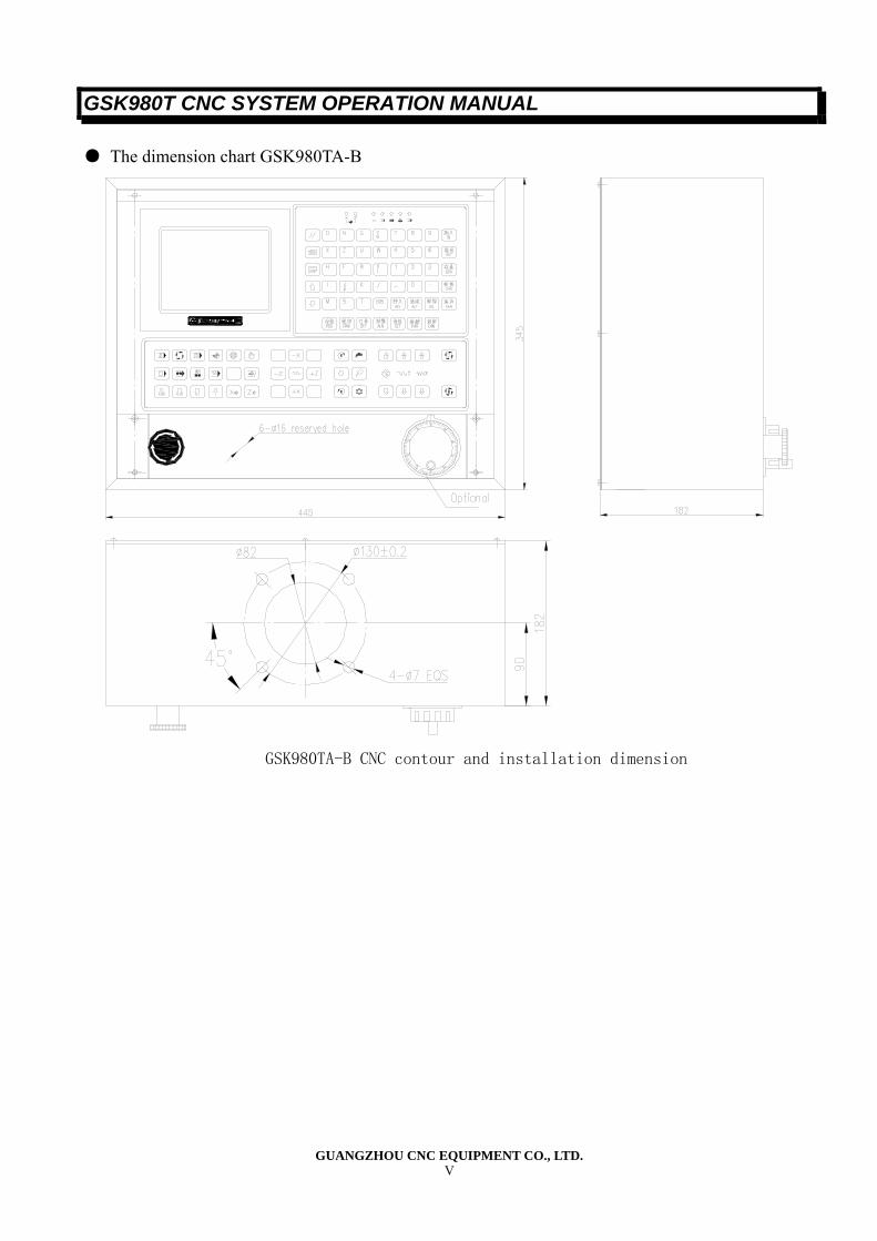
GSK980T CNC SYSTEM OPERATION MANUAL
GUANGZHOU CNC EQUIPMENT CO., LTD. V
● The dimension chart GSK980TA-B
GSK980TA-B CNC contour and installation dimension
MST
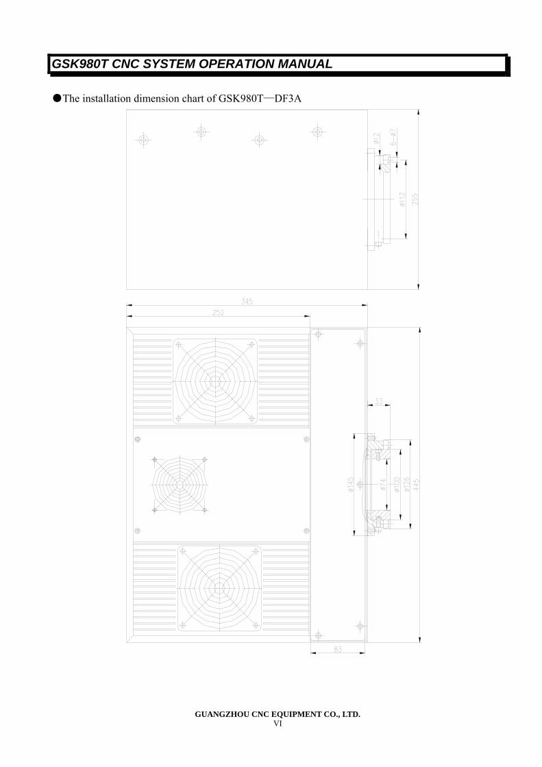
GSK980T CNC SYSTEM OPERATION MANUAL
GUANGZHOU CNC EQUIPMENT CO., LTD. VI
●The installation dimension chart of GSK980T—DF3A
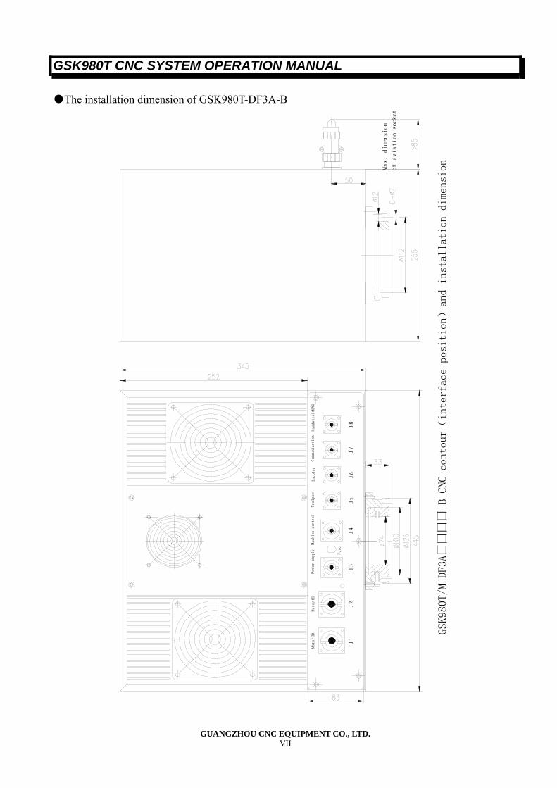
GSK980T CNC SYSTEM OPERATION MANUAL
GUANGZHOU CNC EQUIPMENT CO., LTD. VII
●The installation dimension of GSK980T-DF3A-B
J1
J2
J3
J4
J5
J6
J7
J8
GSK980T/M-DF3A囗囗囗囗-B CNC contour(interface position)
and installation dimension
Max. dimension
of aviation socket
Handwheel(MPG)
Commu
nica
tion
Enc
oder
Toolpost
Mac
hine
con
trol
Power supply Fuse
Motor(X)
Motor(Z)
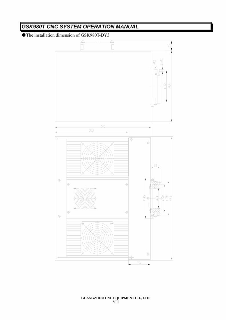
GSK980T CNC SYSTEM OPERATION MANUAL
GUANGZHOU CNC EQUIPMENT CO., LTD. VIII
●The installation dimension of GSK980T-DY3
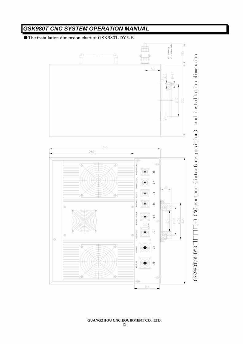
GSK980T CNC SYSTEM OPERATION MANUAL
GUANGZHOU CNC EQUIPMENT CO., LTD. IX
●The installation dimension chart of GSK980T-DY3-B
Motor(X)
Motor(Z)
J1
J2
Mac
hine
con
trol
Pow
ersu
pply
Toolpost
J3
Fuse
J5
J4
Com
muni
cati
onEnc
oder
Handwheel(MPG)
J7
J6
J8
Max
. di
mens
ion
of aviation socket
GSK980T/M-DY3囗囗囗囗-B CNC contour(
interface position) and installation dimension

Add: No.52, 1st Street, Luochong North Road, Luochongwei, Guangzhou, 510165, China
Website: http://www.gsk.com.cn E-mail: [email protected] Tel: 86-20-81796410/81797922 Fax: 86-20-81993683
All specifications and designs are subject to change without notice Oct. 2006/Edition 1
Suit for software version:V06.03.23 Oct. 2006/Printing 1