Embed Size (px)
Citation preview

User Manual for
GPRS Modem Gateway for DeltaLINK-Cloud
Delta-T Devices Ltd
DLC-GPRS -UM-1.1
Copyright
Copyright © 2015 Delta-T Devices Limited. All rights reserved. Under the
copyright laws, this manual may not be copied, in whole or in part, without the
written consent of Delta-T Devices Ltd. Under the law, copying includes
translation into another language.
CE conformity
The CE marking identifies this product as complying with all relevant directives
in the European Union (EU). For use with the GP1, DL6 or GP2 Logger this may
include one or more of the following products:
Product Description Standards
Modem FTX009 Refer to pages 109,110,116 & 117 of AirLink FXT Series Manual v6.1 on the Delta-T Software and Manuals DVD
Solar regulator
Steca Solsum6.6F
2004/108/EC (EMC) 2006/95/EC (Low voltage directive)
Solar panel BP SX series IEC 61215
If the equipment is used with any non Delta-T products it is the responsibility of
the user to ensure the EMC compliance of any such measuring systems.
Design changes
Delta-T Devices Ltd reserves the right to change the designs and specifications
of its products at any time without prior notice.
User Manual Version: 1.1 Nov 2015
Delta-T Devices Ltd Tel: +44 1638 742922 130, Low Road, Burwell Fax: +44 1638 743155 CAMBRIDGE CB25 0EJ e-mail: [email protected]
U.K. www: www.delta-t.co.uk
Contents 3
Contents Contents 3
Scope of This Document 4
Introduction 5
DeltaLINK-Cloud 5 Support for GP1, DL6 or GP2 loggers 7
Health and Safety 8
Installation 8 Batteries 8
Install GPRS Modem Gateway with a GP1, DL6 or GP2 logger 9
Requirements 9 Modem Parts 10 Parts and wiring used with GP2 Loggers 11 Parts and wiring used with GP1 and DL6 loggers 13 1: Ensure SIM Card is properly installed 14 2: Ensure the modem is powered. 15 3: Set up DeltaLINK-Cloud 18
Wiring 25
GPRS Modem Cable Harness for GP2 logger 25 GP2 Network cabling Options with GPRS Modem 25 System Wiring for GP2 Logger with GPRS modem gateway in M-ENCL-B2 metal enclosure 26 GPRS-BX1 Modem Box Wiring Harnesses 27 GPRS-DLC-BX1-SP System Wiring with GP1 Logger 28
Warranty and Service 28
Terms and Conditions of Sale 29 Service, Repairs and Spares 30 Technical Support 30
4 Scope of This Document
Scope of This Document
These instructions describe the use of a modem that communicates with the
DeltaLINK-Cloud in the following systems:_
GPRS DeltaLINK-Cloud Gateway for GP2 loggers: MD-GPRS-DLC: GPRS cloud modem kit for mounting with GP2 Logger into the M-ENCL-B2 metal enclosure. The GP2 logger is mounted inside the metal enclosure. GPRS DeltaLINK-Cloud Gateway for GP1 and/or DL6 loggers: GPRS-DLC-BX1/B: polymer Modem Box with DeltaLINK-Cloud enabled GPRS and battery. GPRS-DLC- BX1/SP: polymer Modem Box with DeltaLINK-Cloud enabled GPRS plus solar power & battery. The GP1 or DL6 logger(s) are mounted outside the box.
Other Documents
You may also need to refer to the following:
- GP2 User Manual
- GP1 Quick Start Guide
- DL6 Quick Start Guide
- Network Cabling for GP1 and DL6
- Deltalink 3.1 or later on-line Help
- Steca Solsum 6.6F Operating Manual
- Solar Panel Manufacturer’s Instructions
- SOL 4 Solar Panel Mounting Bracket Assembly Notes
- Sierra Wireless AirLink FXT Series User Guide v6.1
See also http://www.delta-t.co.uk/DeltaLINK-Cloud.asp
To log in go to www.deltalink-cloud.com
Introduction 5
Introduction
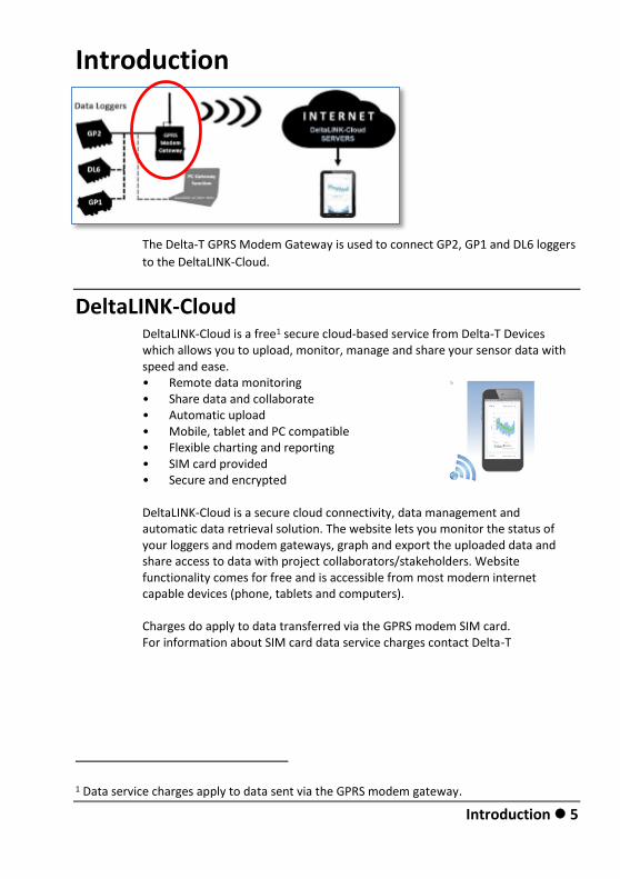
The Delta-T GPRS Modem Gateway is used to connect GP2, GP1 and DL6 loggers
to the DeltaLINK-Cloud.
DeltaLINK-Cloud DeltaLINK-Cloud is a free1 secure cloud-based service from Delta-T Devices which allows you to upload, monitor, manage and share your sensor data with speed and ease. • Remote data monitoring • Share data and collaborate • Automatic upload • Mobile, tablet and PC compatible • Flexible charting and reporting • SIM card provided • Secure and encrypted DeltaLINK-Cloud is a secure cloud connectivity, data management and automatic data retrieval solution. The website lets you monitor the status of your loggers and modem gateways, graph and export the uploaded data and share access to data with project collaborators/stakeholders. Website functionality comes for free and is accessible from most modern internet capable devices (phone, tablets and computers). Charges do apply to data transferred via the GPRS modem SIM card. For information about SIM card data service charges contact Delta-T
1 Data service charges apply to data sent via the GPRS modem gateway.
6 Introduction
Delta-T’s GP2, GP1 and DL6 data loggers can be connected to DeltaLINK-Cloud
using the GPRS modem gateways described in this user manual or via PC based
gateway software (Windows).
Gateway upload schedules can be customised from DeltaLINK-Cloud.
The SIM cards provided by Delta-T for the GPRS Cloud modem enable us to
provide an optimum user experience and support service.
These Smart SIM cards can connect to multiple network providers, which
improves the chance of you having a stable connection.
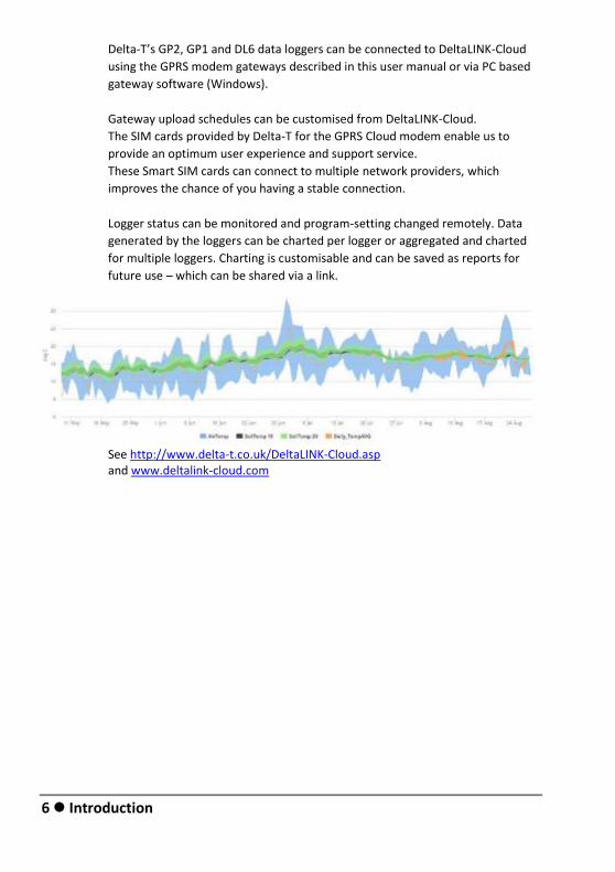
Logger status can be monitored and program-setting changed remotely. Data
generated by the loggers can be charted per logger or aggregated and charted
for multiple loggers. Charting is customisable and can be saved as reports for
future use – which can be shared via a link.
See http://www.delta-t.co.uk/DeltaLINK-Cloud.asp and www.deltalink-cloud.com

Introduction 7
Support for GP1, DL6 or GP2 loggers
Delta-T supplies these systems fully wired up so you don’t have to worry about
wiring. The modem firmware and SIM card are preconfigured at Delta-T with the
system ready to automatically connect to the DeltaLINK-Cloud as soon as it is
powered up.
When you have you registered with the cloud you first create your own gateway
and then tell it which loggers are attached, and it is ready to use.
The modem power comes from an LBAT 4 battery shown in the bottom of both
boxes.
The wiring arrangements of the two systems shown above are slightly different.
This is covered in later sections of this manual.
MD-GPRS-DLC DeltaLINK Cloud - enabled modem with GP2 logger controller in an M-ENCL-B2 metal enclosure with SOL-4 solar power charger/regulator and LBAT4 battery.
GPRS-DLC-BX1/SPDeltaLINK Cloud - enabled modem installed in a polymer Modem Box with SOL-4 solar power charger/regulator and LBAT4 battery.
8 Health and Safety
Health and Safety
Installation
The solar panels should be covered to exclude light before starting the
installation.
Batteries
Batteries that are prone to give off explosive gases at any stage of their charge
or discharge cycle must not be mounted in the enclosure without sufficient
additional ventilation.
Do not use non-approved batteries or other battery charger/regulators in un-
ventilated enclosures.
For optimum thermal protection the Solsum solar charger/regulator should be
installed in the same housing as any external battery.
See also Warnings in the M-ENCL-B User Manual
Install GPRS Modem Gateway with a GP1, DL6 or GP2 logger 9
Install GPRS Modem Gateway with a
GP1, DL6 or GP2 logger
Requirements
1 MD-GPRS-DLC: GPRS cloud modem kit for mounting with GP2 Logger into M-ENCL-B2 metal enclosure or GPRS-DLC-BX1/B: polymer Modem Box with DeltaLINK-Cloud –enabled GPRS and battery or GPRS-DLC- BX1/SP: polymer Modem Box with DeltaLINK-Cloud enabled GPRS modem plus solar power & battery. A source of power is required for the modem, such as the LBAT4 and SOL4 solar power system. At 13.2V the modem’s average consumption is up to 166mA (1.2A peak) when communicating with the DeltaLINK-Cloud servers, and 3-8mA otherwise.
10 Install GPRS Modem Gateway with a GP1, DL6 or GP2 logger
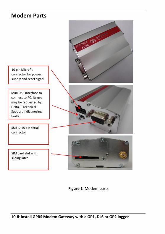
Modem Parts
Figure 1 Modem parts
10 pin Microfit
connector for power
supply and reset signal
Mini USB interface to
connect to PC. Its use
may be requested by
Delta-T Technical
Support if diagnosing
faults
SUB-D 15 pin serial
connector
SIM card slot with
sliding latch
Install GPRS Modem Gateway with a GP1, DL6 or GP2 logger 11
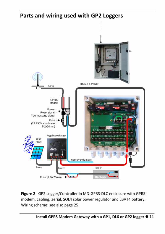
Parts and wiring used with GP2 Loggers
Battery
PowerPower Power
Aerial
Not currently in use
Solar Panel
Modem
RS232 & Power
GPRSModem
PowerReset signal
Text message signal
Regulator/charger
Fuse (2A 250V slow break
5.2x20mm)
BatteryFuse (6.3A 20mm)
Figure 2 GP2 Logger/Controller in MD-GPRS-DLC enclosure with GPRS
modem, cabling, aerial, SOL4 solar power regulator and LBAT4 battery.
Wiring scheme: see also page 25.
12 Install GPRS Modem Gateway with a GP1, DL6 or GP2 logger
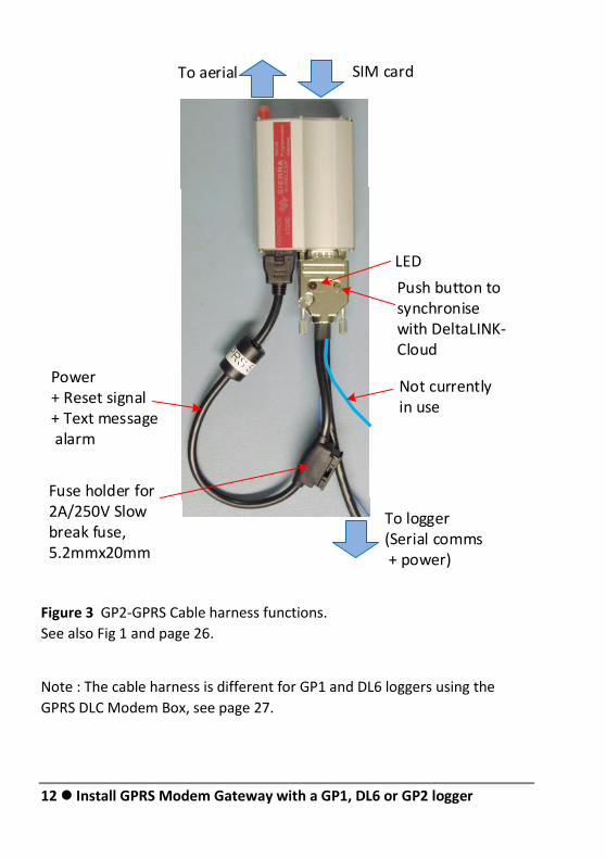
Figure 3 GP2-GPRS Cable harness functions.
See also Fig 1 and page 26.
Note : The cable harness is different for GP1 and DL6 loggers using the
GPRS DLC Modem Box, see page 27.
To aerial
LED
Push button to synchronise with DeltaLINK-Cloud
SIM card
To logger(Serial comms + power)
Not currently in use
Power+ Reset signal+ Text message alarm
Fuse holder for 2A/250V Slow break fuse, 5.2mmx20mm
Install GPRS Modem Gateway with a GP1, DL6 or GP2 logger 13
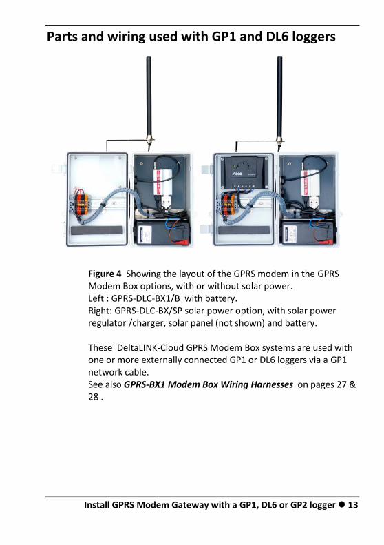
Parts and wiring used with GP1 and DL6 loggers
Figure 4 Showing the layout of the GPRS modem in the GPRS Modem Box options, with or without solar power. Left : GPRS-DLC-BX1/B with battery. Right: GPRS-DLC-BX/SP solar power option, with solar power regulator /charger, solar panel (not shown) and battery. These DeltaLINK-Cloud GPRS Modem Box systems are used with one or more externally connected GP1 or DL6 loggers via a GP1 network cable. See also GPRS-BX1 Modem Box Wiring Harnesses on pages 27 & 28 .

14 Install GPRS Modem Gateway with a GP1, DL6 or GP2 logger
1: Ensure SIM Card is properly installed
The Smart SIM card provided for the DeltaLINK-Cloud Modem gateway has no particular label on it, so all you can do is to check it (apart from actually using it) – is to check the SIM card actually is present in the modem. The GPRS modem is attached inside the box with Velcro and so can be easily removed.
.
Figure 5 Location of the
SIM card
Figure 6 Removal Figure 7 Insertion
Note the slider
used to keep
the SIM card in
place
Install GPRS Modem Gateway with a GP1, DL6 or GP2 logger 15
2: Ensure the modem is powered.
Connect the battery to provide power to the modem.
Powering the modem when using GP2 Logger
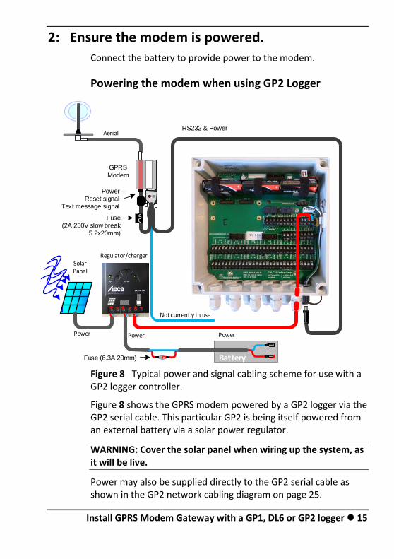
Figure 8 Typical power and signal cabling scheme for use with a GP2 logger controller.
Figure 8 shows the GPRS modem powered by a GP2 logger via the GP2 serial cable. This particular GP2 is being itself powered from an external battery via a solar power regulator.
WARNING: Cover the solar panel when wiring up the system, as it will be live.
Power may also be supplied directly to the GP2 serial cable as shown in the GP2 network cabling diagram on page 25.
Battery
PowerPower Power
Aerial
Not currently in use
Solar Panel
Modem
RS232 & Power
GPRSModem
PowerReset signal
Text message signal
Regulator/charger
Fuse (2A 250V slow break
5.2x20mm)
BatteryFuse (6.3A 20mm)

16 Install GPRS Modem Gateway with a GP1, DL6 or GP2 logger
Powering the modem when using GP1 or DL6 Loggers
Power to the GPRS modem is supplied via the cable harness in
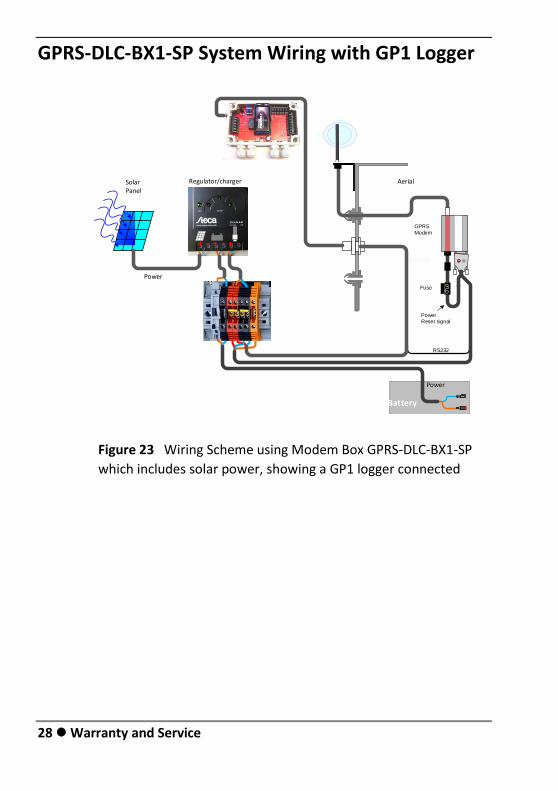
the Modem Box. Power is brought to the DIN rail either directly from the battery via a fuse or indirectly via the solar regulator charger. From the DIN rail it connects to both the modem and also to the external 8-way GP1 network cable socket built into the side of the Modem Box. This means that the battery power is also accessible to any GP1 or DL6 logger externally connected on the GP1 cabling network. (If you don’t want this to happen, the wiring at the DIN rail can easily be altered. See Cable harness wiring scheme on page 27).
WARNING: Cover the solar panel when wiring up the system, as it will be live.
Battery
Power
Power
AerialSolar Panel
Modem
Fuse
GPRS
Modem
Power
Reset signal
Regulator/charger
RS232
Figure 9 Cabling scheme in GPRS Gateway Box type GPRS-DLC-BX1/SP
for use with GP1 or DL6 loggers.
Install GPRS Modem Gateway with a GP1, DL6 or GP2 logger 17
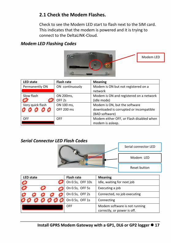
2.1 Check the Modem Flashes.
Check to see the Modem LED start to flash next to the SIM card. This indicates that the modem is powered and it is trying to connect to the DeltaLINK-Cloud.
Modem LED Flashing Codes
LED state Flash rate Meaning
Permanently ON ON continuously Modem is ON but not registered on a network
Slow flash
ON 200ms, OFF 2s
Modem is ON and registered on a network (idle mode)
Very quick flash ON 100 ms, OFF 200 ms
Modem is ON, but the software downloaded is corrupted or incompatible (BAD software)
OFF OFF Modem either OFF, or Flash disabled when modem is asleep.
Serial Connector LED Flash Codes
LED state Flash rate Meaning
On 0.5s, OFF 10s Idle, waiting for next job
On 0.5s, OFF 5s Executing a job
On 0.5s, OFF 2s Connected, no job executing
On 0.5s, OFF 1s Connecting
OFF Modem software is not running correctly, or power is off.
Modem LED
Serial connector LED
Reset button
Modem LED
18 Install GPRS Modem Gateway with a GP1, DL6 or GP2 logger
3: Set up DeltaLINK-Cloud
Requirements
By this stage you should have achieved the following:-
Obtained a Delta-T logger
Obtained a DeltaLINK-Cloud GPRS Modem Gateway, including GPRS modem and SIM card with a data package.
Connected logger to modem
Powered up logger and modem.
Checked modem lights are flashing correctly
You also need an internet connection. This can be a mobile phone, a tablet or a PC or Chrome device. It needs to be running a recent internet browser such as Internet Explorer version 9 or above. You also need an email address.
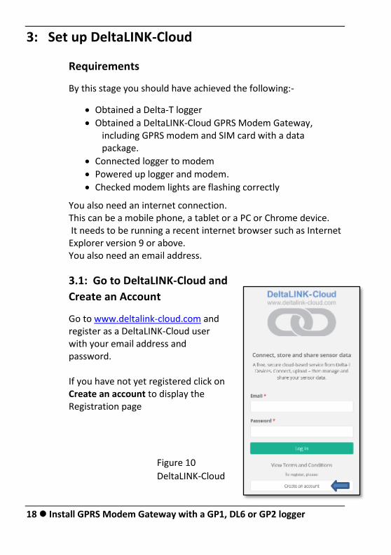
3.1: Go to DeltaLINK-Cloud and
Create an Account
Go to www.deltalink-cloud.com and register as a DeltaLINK-Cloud user with your email address and password. If you have not yet registered click on Create an account to display the Registration page
Figure 10
DeltaLINK-Cloud
Install GPRS Modem Gateway with a GP1, DL6 or GP2 logger 19
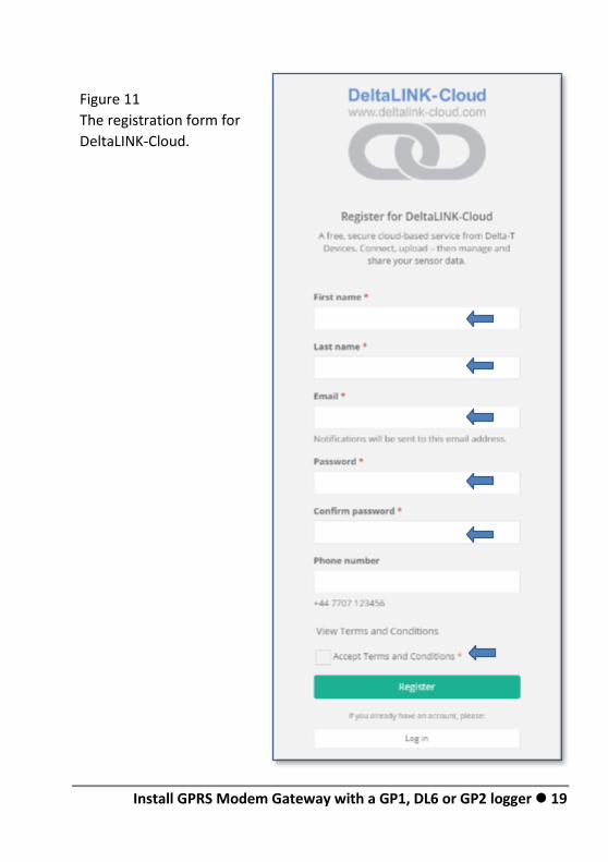
Figure 11
The registration form for
DeltaLINK-Cloud.
20 Install GPRS Modem Gateway with a GP1, DL6 or GP2 logger
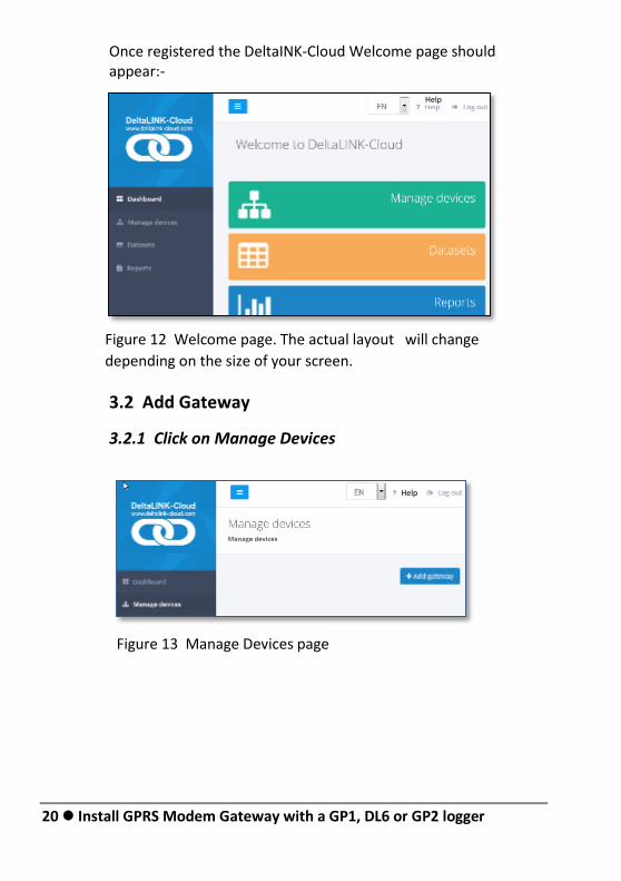
Once registered the DeltaINK-Cloud Welcome page should appear:-
Figure 12 Welcome page. The actual layout will change
depending on the size of your screen.
3.2 Add Gateway
3.2.1 Click on Manage Devices
Figure 13 Manage Devices page
H
elp
Help
Help
Install GPRS Modem Gateway with a GP1, DL6 or GP2 logger 21
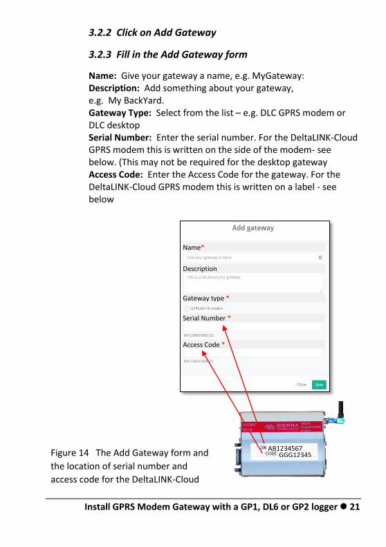
3.2.2 Click on Add Gateway
3.2.3 Fill in the Add Gateway form
Name: Give your gateway a name, e.g. MyGateway: Description: Add something about your gateway, e.g. My BackYard. Gateway Type: Select from the list – e.g. DLC GPRS modem or DLC desktop Serial Number: Enter the serial number. For the DeltaLINK-Cloud GPRS modem this is written on the side of the modem- see below. (This may not be required for the desktop gateway Access Code: Enter the Access Code for the gateway. For the DeltaLINK-Cloud GPRS modem this is written on a label - see below
Name*
Description
Gateway type *
Serial Number *
Access Code *
GGG12345 AB1234567891234
Figure 14 The Add Gateway form and
the location of serial number and
access code for the DeltaLINK-Cloud
GPRS modem
22 Install GPRS Modem Gateway with a GP1, DL6 or GP2 logger
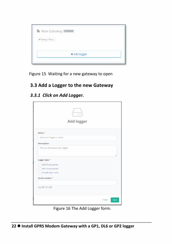
Figure 15 Waiting for a new gateway to open
3.3 Add a Logger to the new Gateway
3.3.1 Click on Add Logger.
Figure 16 The Add Logger form.
Install GPRS Modem Gateway with a GP1, DL6 or GP2 logger 23
Information needed on the Add Logger Form
Name:
In the Add Logger form give your logger a name.
This name will appear in DeltaLINK-Cloud when selecting which
logger to connect to and when looking at the list of datasets
saved to the cloud. It does not appear within the downloaded
data file.
Description:
Tell us a bit about your logger. This information will appear in the Managed Devices list in DetaLINK-Cloud.
Logger type:
Select one from the list provided. This information is needed so that the DeltaLINK-Cloud server knows how to interact with the logger correctly.
Serial Number:
This is required for DeltaLINK-Cloud to connect to the logger e.g GP1-01-024 This information is written on the logger and can also be obtained by connecting directly to the logger from a PC using DeltaLINK. Once you have you have entered this information Click on Save.
24 Install GPRS Modem Gateway with a GP1, DL6 or GP2 logger
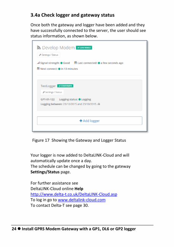
3.4a Check logger and gateway status
Once both the gateway and logger have been added and they have successfully connected to the server, the user should see status information, as shown below.
Your logger is now added to DeltaLINK-Cloud and will automatically update once a day. The schedule can be changed by going to the gateway Settings/Status page. For further assistance see DeltaLINK-Cloud online Help http://www.delta-t.co.uk/DeltaLINK-Cloud.asp To log in go to www.deltalink-cloud.com To contact Delta-T see page 30.
Figure 17 Showing the Gateway and Logger Status
Wiring 25
Wiring
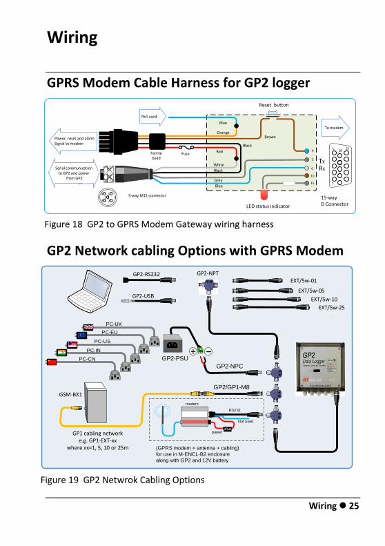
GPRS Modem Cable Harness for GP2 logger
GP2 Network cabling Options with GPRS Modem
GP2-USB
PC-UK
PC-EU
PC-US
PC-IN
PC-CN
EXT/5w-05
EXT/5w-01
EXT/5w-10
EXT/5w-25
GP2-RS232 GP2-NPT
GSM-BX1
GP2-PSU
GP2-NPC
+
GP1 cabling networke.g. GP1-EXT-xx
where xx=1, 5, 10 or 25m
GP2/GP1-M8
Not used
(GPRS modem + antenna + cabling)
for use in M-ENCL-B2 enclosure
along with GP2 and 12V battery
RS232
power
modem
9
2
6
10
15
15-way D Connector
To modem
Black
Grey
Blue1
5 1015
White
45
1
23
5-way M12 connector
Power, reset and alarmSignal to modem
LED status indicator
Reset button
RX
TX
Serial communication to GP2 and power
from GP2
Ferritebead
BrownOrange
Blue
Red
Black
Fuse
Not used
Figure 18 GP2 to GPRS Modem Gateway wiring harness
Figure 19 GP2 Netwrok Cabling Options
26 Wiring
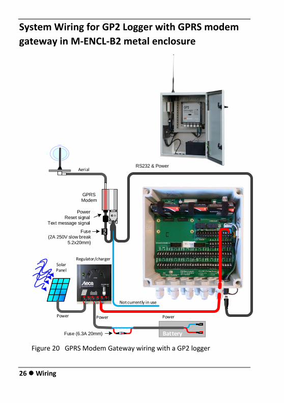
System Wiring for GP2 Logger with GPRS modem
gateway in M-ENCL-B2 metal enclosure
Battery
PowerPower Power
Aerial
Not currently in use
Solar Panel
Modem
RS232 & Power
GPRSModem
PowerReset signal
Text message signal
Regulator/charger
Fuse (2A 250V slow break
5.2x20mm)
BatteryFuse (6.3A 20mm)
Figure 20 GPRS Modem Gateway wiring with a GP2 logger
Wiring 27
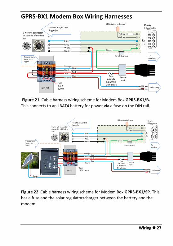
GPRS-BX1 Modem Box Wiring Harnesses
Figure 21 Cable harness wiring scheme for Modem Box GPRS-BX1/B.
This connects to an LBAT4 battery for power via a fuse on the DIN rail.
Figure 22 Cable harness wiring scheme for Modem Box GPRS-BX1/SP. This
has a fuse and the solar regulator/charger between the battery and the
modem.
9
2
6
10
15
15-way D Connector
To modem
1
5 1015
5-way M8 connector on outside of Modem Box
LED status indicator
Reset button
RX
TX
Ferritebead
Fuse2A 250V
5.2x20mmSlow break
241
53
To GP1 and/or DL6 logger(s)
To battery
Optional alarmsignal from logger
DIN rail
Fuse 6.3 A 20mm
OrangeBlue
BlackRed
RedBlue
Brown
Blue
Grey
White
Black Green
Grey
Grey 1k8
9
2
6
10
15
15-way D Connector
To modem
1
5 1015
5-way M8 connector on outside of Modem Box
LED status indicator
Reset button
RX
TX
Ferritebead
Fuse2A 250V
5.2x20mmSlow break
241
53
To GP1 and/or DL6 logger(s)
To batteryDIN rail
Fuse 6.3A 20mm
OrangeBlue
BlackRed
RedBlue
Brown
Blue
Grey
White
Black Green
Grey
Grey 1k8
Optional alarmsignal from logger
BrownBlue
28 Warranty and Service
GPRS-DLC-BX1-SP System Wiring with GP1 Logger
Figure 23 Wiring Scheme using Modem Box GPRS-DLC-BX1-SP
which includes solar power, showing a GP1 logger connected
Battery
Power
Power
AerialSolar Panel
Modem
Fuse
GPRS
Modem
Power
Reset signal
Regulator/charger
RS232
Warranty and Service 29
Warranty and Service
Terms and Conditions of Sale Our Conditions of Sale (ref: COND: 1/07) set out Delta-T's legal obligations on these matters. The following paragraphs summarise Delta-T's position but reference should always be made to the exact terms of our Conditions of Sale, which will prevail over the following explanation.
Delta-T warrants that the goods will be free from defects arising out of the materials used or poor workmanship for a period of two years from the date of delivery.
Delta-T shall be under no liability in respect of any defect arising from fair wear and tear, and the warranty does not cover damage through misuse or inexpert servicing, or other circumstances beyond their control.
If the buyer experiences problems with the goods they shall notify Delta-T (or Delta-T’s local distributor) as soon as they become aware of such problem.
Delta-T may rectify the problem by replacing faulty parts free of charge, or by repairing the goods free of charge at Delta-T's premises in the UK during the warranty period.
If Delta-T requires that goods under warranty be returned to them from overseas for repair, Delta-T shall not be liable for the cost of carriage or for customs clearance in respect of such goods. However, Delta-T requires that such returns are discussed with them in advance and may at their discretion waive these charges.
Delta-T shall not be liable to supply products free of charge or repair any goods where the products or goods in question have been discontinued or have become obsolete, although Delta-T will endeavour to remedy the buyer’s problem.
Delta-T shall not be liable to the buyer for any consequential loss, damage or compensation whatsoever (whether caused by the negligence of the Delta-T, their employees or distributors or otherwise) which arise from the supply of the goods and/or services, or their use or resale by the buyer.
Delta-T shall not be liable to the buyer by reason of any delay or failure to perform their obligations in relation to the goods and/or services if the delay or failure was due to any cause beyond the Delta-T’s reasonable control.
30 Warranty and Service
Service, Repairs and Spares Users in countries that have a Delta-T distributor or technical representative should contact them in the first instance.
Spare parts for our own instruments can be supplied and can normally be despatched within a few working days of receiving an order.
Spare parts and accessories for products not manufactured by Delta-T may have to be obtained from our supplier, and a certain amount of additional delay is inevitable.
No goods or equipment should be returned to Delta-T without first obtaining the return authorisation from Delta-T or our distributor.
On receipt of the goods at Delta-T you will be given a reference number. Always refer to this reference number in any subsequent correspondence. The goods will be inspected and you will be informed of the likely cost and delay.
We normally expect to complete repairs within one or two weeks of receiving the equipment. However, if the equipment has to be forwarded to our original supplier for specialist repairs or recalibration, additional delays of a few weeks may be expected. For contact details see below.
Technical Support Users in countries that have a Delta-T distributor or technical representative should contact them in the first instance.
Technical Support is available on Delta-T products and systems. Your initial enquiry will be acknowledged immediately with a reference number. Make sure to quote the reference number subsequently so that we can easily trace any earlier correspondence.
In your enquiry, always quote instrument serial numbers, software version numbers, and the approximate date and source of purchase where these are relevant.
Contact Details:
Tech Support Team Delta-T Devices Ltd 130 Low Road, Burwell, Cambridge CB25 0EJ, UK email: [email protected] email: [email protected] web: www.delta-t.co.uk Tel: +44 (0)1638 742922 Fax: +44 (0)1638 743155

![1.2 Setting GPRS/GSM Modem - DuraTech USA, Inc. to setup GPRS_GSM... · 1.2 Setting GPRS/GSM Modem 1. Open “ Control Panel “ from [Start] menu, select [Phone and Modem Options]](https://img.pdfslide.us/doc/110x75/5a95c6ca7f8b9ad96f8c9f53/12-setting-gprsgsm-modem-duratech-usa-inc-to-setup-gprsgsm12-setting.jpg)