Embed Size (px)
Citation preview

USER MANUAL Fixturlaser SMC

USER MANUAL FIXTURLASER SMC, edition 1.3 (November 2017)
CONTENT
General presentation 1.1
General settings 2.1
Supervisor module 3.1
Balancing module 4.1
Maintenance 5.1
Technical specification 6.1

1.1
1 GENERAL PRESENTATION
1.1 INTRODUCTION
We want to congratulate you on your choice and hope that you will be fully satisfied with it. For this
reason, we recommend that you read carefully the present user guide and more specifically the safety
instructions.
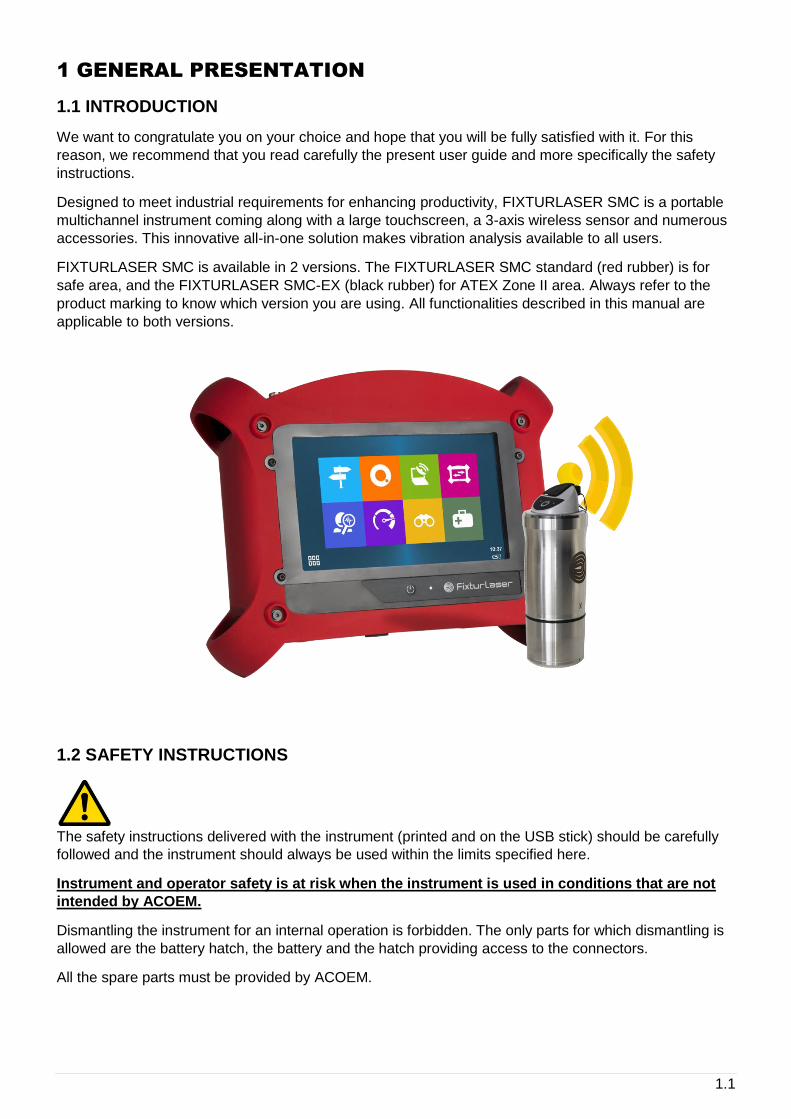
Designed to meet industrial requirements for enhancing productivity, FIXTURLASER SMC is a portable
multichannel instrument coming along with a large touchscreen, a 3-axis wireless sensor and numerous
accessories. This innovative all-in-one solution makes vibration analysis available to all users.
FIXTURLASER SMC is available in 2 versions. The FIXTURLASER SMC standard (red rubber) is for
safe area, and the FIXTURLASER SMC-EX (black rubber) for ATEX Zone II area. Always refer to the
product marking to know which version you are using. All functionalities described in this manual are
applicable to both versions.
1.2 SAFETY INSTRUCTIONS
The safety instructions delivered with the instrument (printed and on the USB stick) should be carefully
followed and the instrument should always be used within the limits specified here.
Instrument and operator safety is at risk when the instrument is used in conditions that are not
intended by ACOEM.
Dismantling the instrument for an internal operation is forbidden. The only parts for which dismantling is
allowed are the battery hatch, the battery and the hatch providing access to the connectors.
All the spare parts must be provided by ACOEM.
1.2
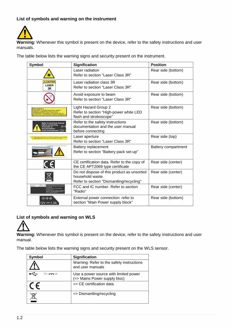
List of symbols and warning on the instrument
Warning: Whenever this symbol is present on the device, refer to the safety instructions and user
manuals.
The table below lists the warning signs and security present on the instrument.
Symbol Signification Position
Laser radiation
Refer to section "Laser Class 3R"
Rear side (bottom)
Laser radiation class 3R
Refer to section "Laser Class 3R"
Rear side (bottom)
Avoid exposure to beam
Refer to section "Laser Class 3R"
Rear side (bottom)
Light Hazard Group 2
Refer to section "High-power white LED flash and stroboscope"
Rear side (bottom)
Refer to the safety instructions documentation and the user manual before connecting
Rear side (bottom)
Laser aperture
Refer to section "Laser Class 3R"
Rear side (top)
Battery replacement
Refer to section "Battery pack set-up"
Battery compartment
CE certification data. Refer to the copy of the CE APT2069 type certificate
Rear side (center)
Do not dispose of this product as unsorted household waste.
Refer to section "Dismantling/recycling"
Rear side (center)
FCC and IC number. Refer to section "Radio"
Rear side (center)
External power connection: refer to section "Main Power supply block"
Rear side (bottom)
List of symbols and warning on WLS
Warning: Whenever this symbol is present on the device, refer to the safety instructions and user
manual.
The table below lists the warning signs and security present on the WLS sensor.
Symbol Signification
Warning: Refer to the safety instructions and user manuals
Use a power source with limited power (=> Mains Power supply bloc)
=> CE certification data
=> Dismantling/recycling
1.3
Laser
Laser maintenance: The laser does not need maintenance or adjustment excluding cleaning the glass
with a cotton swab. Always shut off completely the device FIXTURLASER SMC before this operation.
Caution: Use of controls or adjustments or performance of procedures other than those specified herein
may result in hazardous radiation exposure.
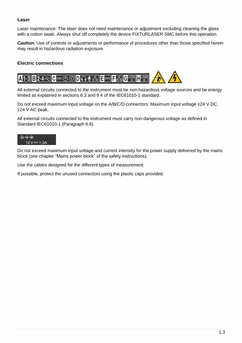
Electric connections
All external circuits connected to the instrument must be non-hazardous voltage sources and be energy
limited as explained in sections 6.3 and 9.4 of the IEC61010-1 standard.
Do not exceed maximum input voltage on the A/B/C/D connectors: Maximum input voltage ±24 V DC,
±24 V AC peak.
All external circuits connected to the instrument must carry non-dangerous voltage as defined in
Standard IEC61010-1 (Paragraph 6.6)
Do not exceed maximum input voltage and current intensity for the power supply delivered by the mains
block (see chapter “Mains power block” of the safety instructions).
Use the cables designed for the different types of measurement.
If possible, protect the unused connectors using the plastic caps provided.
1.4
1.3 FIRST POWER UP
The instrument turns on automatically a few seconds after being connected to the mains through the
power supply module. If the battery level is too low, the charge starts and goes on as long as the
instrument is connected to its power supply.
When using a new battery, leave the battery in charge for about 10 hours in order to achieve full charge.
Do not use the instrument prior to 2-3 hours of charge. Usual charging time is about 6 hours when
instrument is switched off.
On-Off
• Power on: Press the On-Off key
• Power off: Press the On-Off key, then message “Shutdown”
Battery charge
• Power off: Press the On-Off key, then message “Shutdown”
• Connect the charger on the main. The instrument is automatically powered on. During the charge,
you can continue to use it. For a faster charge, it is recommended to switch-off the instrument. A full
charge requires about 6 hours.
It is recommended to disconnect the charger from the main when you are not using it.

1.5
1.4 USER INTERFACE
FIXTURLASER SMC starts on its “Home screen”. It is a touch screen and a simple pressure on it gives
access to the application modules installed on the instrument and to 2 side panels:
For more details:
• Supervisor module: See CHAPTER 3
• Balancing module: See CHAPTER 4
• Status panel: See § 1.9
• Shortcuts panel: See § 1.10
The 2 side panels are accessible from any screen.
Access to application modules
Access to status side panel
Access to shortcuts side panel
1.6
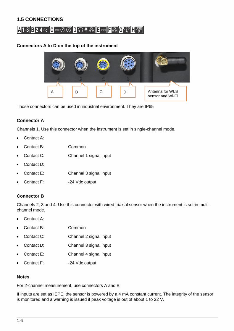
1.5 CONNECTIONS
Connectors A to D on the top of the instrument
Those connectors can be used in industrial environment. They are IP65
Connector A
Channels 1. Use this connector when the instrument is set in single-channel mode.
• Contact A:
• Contact B: Common
• Contact C: Channel 1 signal input
• Contact D:
• Contact E: Channel 3 signal input
• Contact F: -24 Vdc output
Connector B
Channels 2, 3 and 4. Use this connector with wired triaxial sensor when the instrument is set in multi-
channel mode.
• Contact A:
• Contact B: Common
• Contact C: Channel 2 signal input
• Contact D: Channel 3 signal input
• Contact E: Channel 4 signal input
• Contact F: -24 Vdc output
Notes
For 2-channel measurement, use connectors A and B
If inputs are set as IEPE, the sensor is powered by a 4 mA constant current. The integrity of the sensor
is monitored and a warning is issued if peak voltage is out of about 1 to 22 V.
A B C D Antenna for WLS sensor and Wi-Fi
1.7
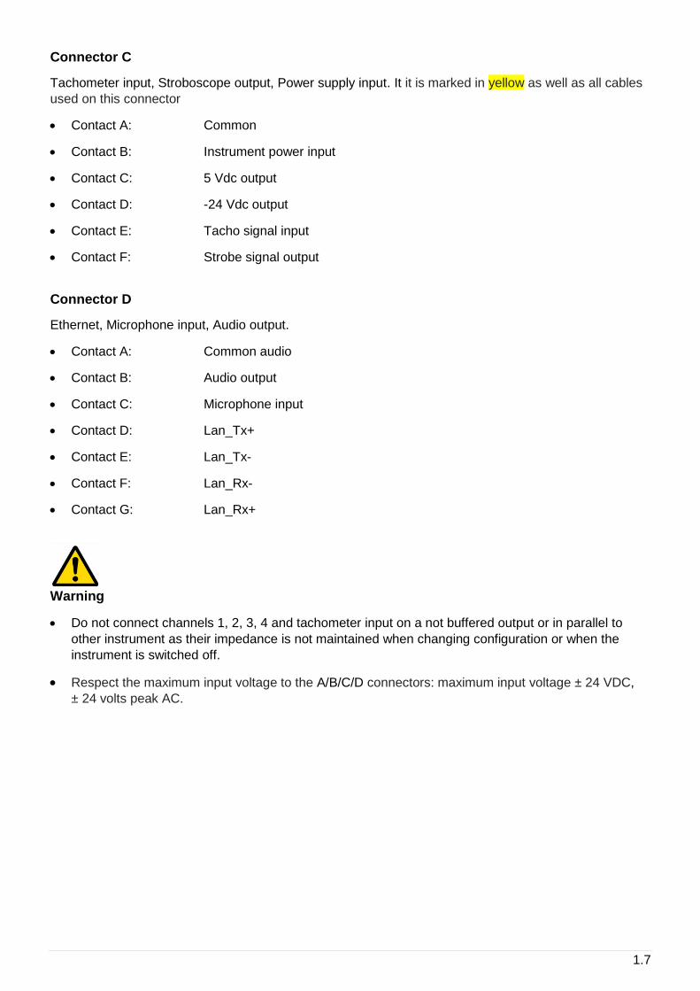
Connector C
Tachometer input, Stroboscope output, Power supply input. It it is marked in yellow as well as all cables
used on this connector
• Contact A: Common
• Contact B: Instrument power input
• Contact C: 5 Vdc output
• Contact D: -24 Vdc output
• Contact E: Tacho signal input
• Contact F: Strobe signal output
Connector D
Ethernet, Microphone input, Audio output.
• Contact A: Common audio
• Contact B: Audio output
• Contact C: Microphone input
• Contact D: Lan_Tx+
• Contact E: Lan_Tx-
• Contact F: Lan_Rx-
• Contact G: Lan_Rx+
Warning
• Do not connect channels 1, 2, 3, 4 and tachometer input on a not buffered output or in parallel to
other instrument as their impedance is not maintained when changing configuration or when the
instrument is switched off.
• Respect the maximum input voltage to the A/B/C/D connectors: maximum input voltage ± 24 VDC,
± 24 volts peak AC.
1.8
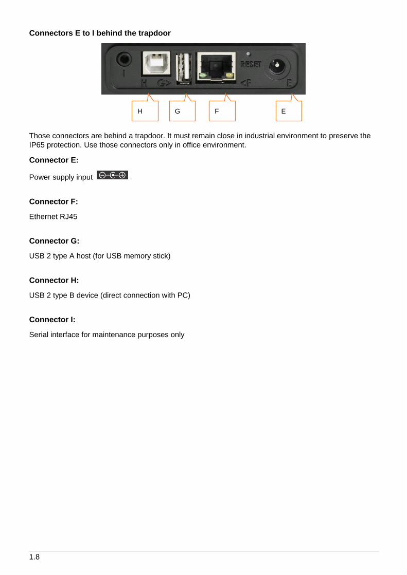
Connectors E to I behind the trapdoor
Those connectors are behind a trapdoor. It must remain close in industrial environment to preserve the
IP65 protection. Use those connectors only in office environment.
Connector E:
Power supply input
Connector F:
Ethernet RJ45
Connector G:
USB 2 type A host (for USB memory stick)
Connector H:
USB 2 type B device (direct connection with PC)
Connector I:
Serial interface for maintenance purposes only
E F G H
1.9
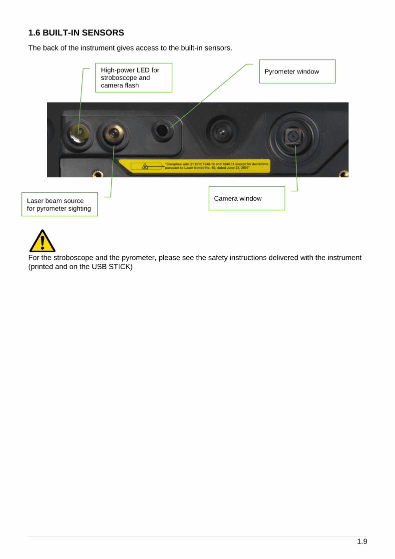
1.6 BUILT-IN SENSORS
The back of the instrument gives access to the built-in sensors.
For the stroboscope and the pyrometer, please see the safety instructions delivered with the instrument
(printed and on the USB STICK)
High-power LED for stroboscope and camera flash
Laser beam source for pyrometer sighting
Pyrometer window
Camera window
1.10
1.7 WIRELESS SENSOR
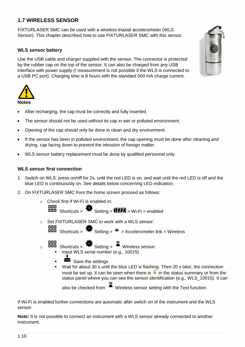
FIXTURLASER SMC can be used with a wireless triaxial accelerometer (WLS
Sensor). This chapter described how to use FIXTURLASER SMC with this sensor.
WLS sensor battery
Use the USB cable and charger supplied with the sensor. The connector is protected
by the rubber cap on the top of the sensor. It can also be charged from any USB
interface with power supply (! measurement is not possible if the WLS is connected to
a USB PC port). Charging time is 8 hours with the standard 500 mA charge current.
Notes
• After recharging, the cap must be correctly and fully inserted.
• The sensor should not be used without its cap in wet or polluted environment.
• Opening of the cap should only be done in clean and dry environment.
• If the sensor has been in polluted environment, the cap opening must be done after cleaning and
drying, cap facing down to prevent the intrusion of foreign matter.
• WLS sensor battery replacement must be done by qualified personnel only.
WLS sensor first connection
1. Switch on WLS: press on/off for 2s, until the red LED is on, and wait until the red LED is off and the
blue LED is continuously on. See details below concerning LED indication.
2. On FIXTURLASER SMC from the home screen proceed as follows:
o Check first if Wi-Fi is enabled in:
Shortcuts > Setting > > Wi-Fi = enabled
o Set FIXTURLASER SMC to work with a WLS sensor:
Shortcuts > Setting > > Accelerometer link = Wireless
o Shortcuts > Setting > Wireless sensor: ▪ Input WLS serial number (e.g., 10015)
▪ Save the settings ▪ Wait for about 30 s until the blue LED is flashing. Then 20 s later, the connection
must be set up. It can be seen when there is in the status summary or from the status panel where you can see the sensor identification (e.g., WLS_10015). It can
also be checked from Wireless sensor setting with the Test function.
If Wi-Fi is enabled further connections are automatic after switch on of the instrument and the WLS
sensor.
Note: It is not possible to connect an instrument with a WLS sensor already connected to another
instrument.

1.11
WLS sensor switch off
Press on/off for 6s until the red LED flashes on. The sensor is also automatically switched off if there is
no connectivity during 10 min.
WLS LED indication Red LED Blue LED Significance
WLS connected to the charger
——— Charge in progress (LED brightness = 50%)
━━━━ Charge completed (LED brightness = 100%)
- - - - - Charge error
Switch on
(press 2s on/off)
——— (< 10 s) Off Start in progress
——— (> 15 s) Off Error
———
WLS ready and not connected to the instrument
- - - - - WLS has detected the instrument. The connection is only effective when you
have in FIXTURLASER SMC status summary
Switch off
(press 7 s on/off)
- - - - - Stop in progress
Off Off WLS is switched off
Low battery - - - - -
Notation:
━━━━ brightness = 100%
——— brightness = 50%
- - - - - flashing
Blank any status
1.12
1.8 CONNECTION WITH PC
FIXTURLASER SMC can exchange data with the PC when the Communication module is run from
the home screen. See below the different settings according to the type of communication. Once the
communication is established the instrument is seen as an external drive from the PC (see § 6.1).
Using USB (Connector H)
No settings are required, the PC automatically detects the instrument after its connection.
Using USB memory (Connector G)
It is possible to use a USB memory stick connected on port G to exchange the following data:
• Firmware update: see § 2.11
• Issue balancing reports: see § 4.13
• Issue diagnostic reports: see § 3.7
• Copy screenshots taken with the device: see § 1.10
Note: USB memory stick format must be FAT32, NTFS format is not accepted. It is always possible to
reformat it to FAT32.
Using Ethernet (Connector D or F)
• Direct connection PC- FIXTURLASER SMC setting:
o On PC: Setup Network ▪ DHCP = No ▪ Set the IP address: Ex 192.168.1.10 ▪ Mask = 255.255.255.0
o On FIXTURLASER SMC:
Shortcuts > Setting > Network >
▪ DHCP = No ▪ Set the IP address = e.g., 192.168.1.12
Note: the first 3 numbers must be the same (192.168.1) and the last one different from that of the PC (10 ≠ 12)
▪ Mask = 255.255.255.0
Once the setting is done, to access the data use FIXTURLASER SMC IP address, e.g., in
the Explorer type “\\192.168.1.10\Data”.
• PC- FIXTURLASER SMC connection through LAN Network:
o On PC: Setup Network ▪ DHCP = Yes
o On FIXTURLASER SMC:
Shortcuts > Setting > Network >
▪ DHCP = Yes
1.13
Connect FIXTURLASER SMC to the LAN, set it in communication mode and wait
until it gets its IP address.
The IP address can be read in Setting > About information page.
If there is a DNS, it is also possible to access the instrument with its name. The name is
FIXTURLASER SMC_serial_number (e.g., FIXTURLASER SMC_10015).
Once the setting is done, to access the data use FIXTURLASER SMC IP address, e.g., in
the Explorer type “\\FIXTURLASER SMC_10015\Data”.
Using Wi-Fi
Check first if Wi-Fi is enabled in:
Shortcuts > Setting > > Wi-Fi = enabled
• Direct Wi-Fi connection PC- FIXTURLASER SMC setting without WLS sensor:
o On FIXTURLASER SMC:
Setting > Network > Wi-Fi part
▪ Enabled = Yes ▪ Adhoc = Yes ▪ SSID = My_FIXTURLASER SMC or other ▪ Canal = 6 ▪ Authentication = none ▪ DHCP = No ▪ Set the IP address: Ex 192.168.1.16
Note: the first 3 numbers must be the same (192.168.1) and the last one different from that of the PC (14 ≠ 16)
▪ Mask = 255.255.255.0
o On PC: Setup WIFI network ▪ DHCP = No ▪ Set the IP address, e.g., 192.168.1.14 ▪ Mask: 255.255.255.0 ▪ Scan Wi-Fi networks and select FIXTURLASER SMC SSID.
Once the setting is done, to access the data use FIXTURLASER SMC IP address, e.g., in
the Explorer type “\\192.168.1.16\Data”.
• Direct Wi-Fi connection PC- FIXTURLASER SMC-WLS setting:
o On FIXTURLASER SMC: ▪ First set the connection FIXTURLASER SMC-WLS: see § 1.7
▪ Wait for sensor connection ( in status summary)
o On PC: Setup Wi-Fi network ▪ DHCP = Yes ▪ Scan Wi-Fi networks and select FIXTURLASER SMC SSID (WLS_10015). ▪ Input the security key: WLS serial number (Ex: 10015)
Once the setting is done, to access the data use FIXTURLASER SMC name, e.g., in the
Explorer type “\\FIXTURLASER SMC_10015\Data”.
1.14
• Wi-Fi LAN connection PC- FIXTURLASER SMC setting without WLS sensor:
Note: WLS sensor cannot be used simultaneously with this mode.
o On FIXTURLASER SMC:
Setting > Network > Wi-Fi part
▪ Enabled: Yes ▪ Adhoc: No
▪ Save the setting
Setting > Network > Wi-Fi part
▪ Scan network until you detect the right SSID ▪ Set Authentication, Encryption and Key according to selected SSID ▪ DHCP: Yes
The IP address can be read in Setting > About information page.
If there is a DNS, it is also possible to access the instrument with its name. The name is:
FIXTURLASER SMC_serial_number (e.g., FIXTURLASER SMC_10015).
o On PC: the PC must also be connected to the same Wi-Fi LAN
1.15
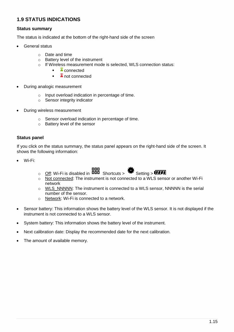
1.9 STATUS INDICATIONS
Status summary
The status is indicated at the bottom of the right-hand side of the screen
• General status
o Date and time o Battery level of the instrument o If Wireless measurement mode is selected, WLS connection status:
▪ connected
▪ not connected
• During analogic measurement
o Input overload indication in percentage of time. o Sensor integrity indicator
• During wireless measurement
o Sensor overload indication in percentage of time. o Battery level of the sensor
Status panel
If you click on the status summary, the status panel appears on the right-hand side of the screen. It
shows the following information:
• Wi-Fi:
o Off: Wi-Fi is disabled in Shortcuts > Setting > o Not connected: The instrument is not connected to a WLS sensor or another Wi-Fi
network o WLS_NNNNN: The instrument is connected to a WLS sensor, NNNNN is the serial
number of the sensor. o Network: Wi-Fi is connected to a network.
• Sensor battery: This information shows the battery level of the WLS sensor. It is not displayed if the
instrument is not connected to a WLS sensor.
• System battery: This information shows the battery level of the instrument.
• Next calibration date: Display the recommended date for the next calibration.
• The amount of available memory.
1.16
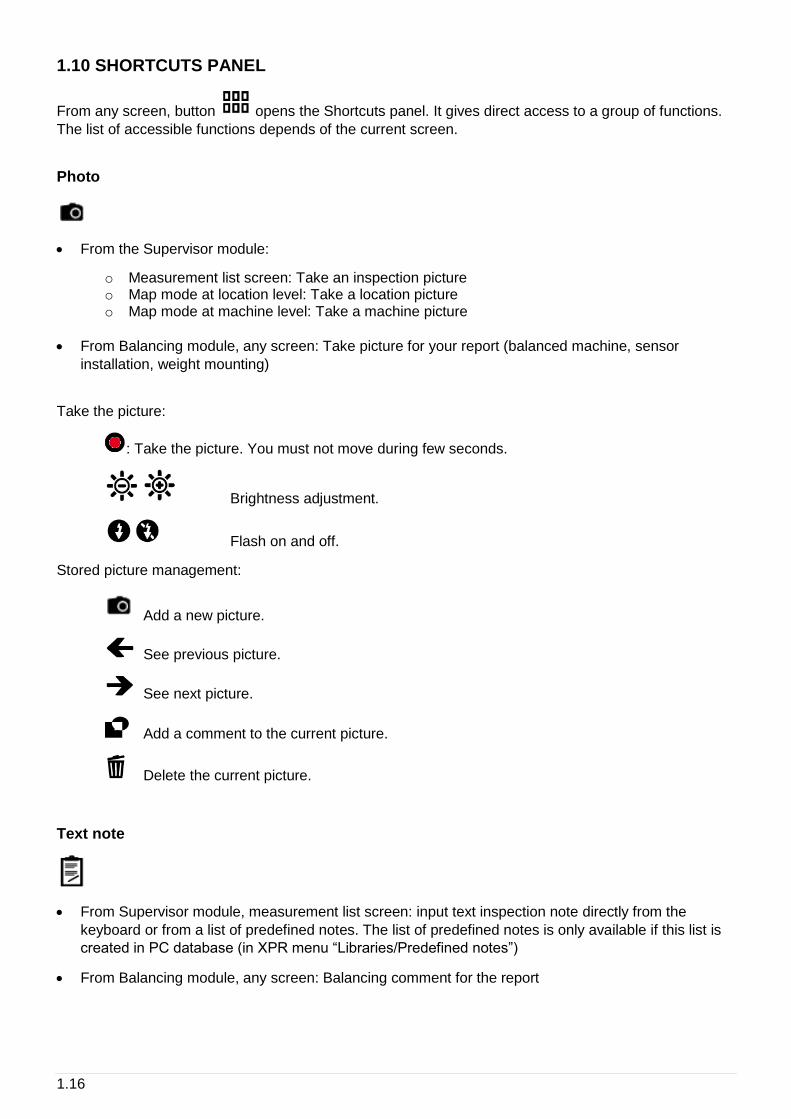
1.10 SHORTCUTS PANEL
From any screen, button opens the Shortcuts panel. It gives direct access to a group of functions.
The list of accessible functions depends of the current screen.
Photo
• From the Supervisor module:
o Measurement list screen: Take an inspection picture o Map mode at location level: Take a location picture o Map mode at machine level: Take a machine picture
• From Balancing module, any screen: Take picture for your report (balanced machine, sensor
installation, weight mounting)
Take the picture:
: Take the picture. You must not move during few seconds.
Brightness adjustment.
Flash on and off.
Stored picture management:
Add a new picture.
See previous picture.
See next picture.
Add a comment to the current picture.
Delete the current picture.
Text note
• From Supervisor module, measurement list screen: input text inspection note directly from the
keyboard or from a list of predefined notes. The list of predefined notes is only available if this list is
created in PC database (in XPR menu “Libraries/Predefined notes”)
• From Balancing module, any screen: Balancing comment for the report
1.17
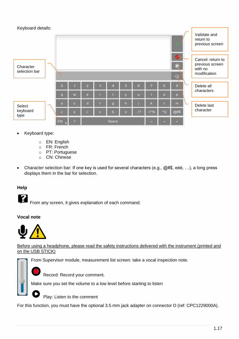
Keyboard details:
• Keyboard type:
o EN: English o FR: French o PT: Portuguese o CN: Chinese
• Character selection bar: If one key is used for several characters (e.g., @#$, eéè, …), a long press
displays them in the bar for selection.
Help
From any screen, it gives explanation of each command.
Vocal note
Before using a headphone, please read the safety instructions delivered with the instrument (printed and
on the USB STICK)
From Supervisor module, measurement list screen: take a vocal inspection note.
Record: Record your comment.
Make sure you set the volume to a low level before starting to listen
Play: Listen to the comment
For this function, you must have the optional 3.5 mm jack adapter on connector D (ref: CPC1229000A).
Select keyboard type
Character selection bar
Validate and return to previous screen
Cancel: return to previous screen with no modification
Delete all characters
Delete last character
1.18
Listening to the signal
Before using a headphone, please read the safety instructions delivered with the instrument (printed and
on the USB STICK)
• From the Supervisor module, measurement list screen: listen to the signal of the sensor
• From the Supervisor module, time wave display screen: listen to the recorded signal
Make sure to set the volume to a low level before starting to listen
Press to start and then adjust the level to your convenience.
For this function, you must have the optional 3.5 mm jack adapter on connector D (ref:
CPC1229000A).
Note: If a triaxial sensor is used, the live output is the Z axis of the sensor.
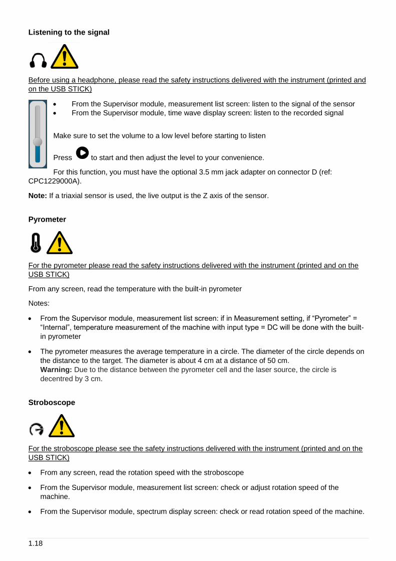
Pyrometer
For the pyrometer please read the safety instructions delivered with the instrument (printed and on the
USB STICK)
From any screen, read the temperature with the built-in pyrometer
Notes:
• From the Supervisor module, measurement list screen: if in Measurement setting, if “Pyrometer” =
“Internal”, temperature measurement of the machine with input type = DC will be done with the built-
in pyrometer
• The pyrometer measures the average temperature in a circle. The diameter of the circle depends on
the distance to the target. The diameter is about 4 cm at a distance of 50 cm.
Warning: Due to the distance between the pyrometer cell and the laser source, the circle is
decentred by 3 cm.
Stroboscope
For the stroboscope please see the safety instructions delivered with the instrument (printed and on the
USB STICK)
• From any screen, read the rotation speed with the stroboscope
• From the Supervisor module, measurement list screen: check or adjust rotation speed of the
machine.
• From the Supervisor module, spectrum display screen: check or read rotation speed of the machine.
1.19
Fine tune. A continuous press speeds up the modification
Fast tune. A continuous press speeds up the modification
Divide or Multiply the value by 2.
Set the flash duration: default value is 5 degrees. The longer the duration, the brighter the
flash, but the fuzzier the target on the rotor. Limits range from 0.5 to 15 degrees.
This function is only accessible in Supervisor module.
Notes:
• It is recommended to start with a frequency higher than the rotation and decrease gradually until
stopping the rotor marker.
• Default unit is set in "Spectrum display" parameters (see § 2.4)
• Once the marker is stopped, to be sure not to be on a sub-multiple of the rotation, use , the
marker should appear 2 times. Use to return to the initial frequency.
Screenshot
From anywhere, you can save a screen copy. Images are stored in folder “Screenshots”. Connect your
PC to FIXTURLASER SMC to copy them (see § 1.8).
Settings
See CHAPTER 2.
Home
From anywhere you can go directly to the home screen.

1.20
1.11 BATTERY MANAGEMENT
For battery management, please read the safety instructions delivered with the instrument (printed and
on the USB Stick)
Battery information
• Reference: FLC1007000
• Part number: WILPA2344x
• Configuration: 1S3P INT 176065
• Rated energy: 75 Wh
This battery model and its cells meet the requirement of the current applicable "Recommendations on
the Transport of Dangerous Goods, part III, sub-section 38.3, Manual of Tests and Criteria” issued by
the United Nations Committee of Experts on the Transportation of Dangerous Goods.
In accordance with the current UN Recommendations on the Transport of Dangerous Goods Model, this
lithium battery is assigned for transportation under the following entries:
• If shipped as such, UN Dangerous Goods Entry is: UN 3480
• If shipped contained in the instrument, UN Dangerous Goods Entry is: UN 3481
Battery charge
When using a new battery, leave the battery in charge for about 10 hours in order to achieve full charge.
Do not use the instrument prior to 2-3 hours of charge. Usual charging time is about 6 hours when
instrument is switched off.
• Battery charge:
o Connect the instrument to the charger delivered with the instrument. o Connect the charger to the mains. The instrument is automatically powered up. During the
charge, you can continue using it. For a faster charge, it is recommended to switch the instrument off. A full charge requires about 6 hours.
It is recommended to disconnect the charger from the mains when you are not using it.
Battery replacement
• Safety instructions:
o Do not use batteries other than type PIL1133 provided for FIXTURLASER SMC and identified as 01dB Metravib WILPA 2344A
1.21
o Do not open or disassemble the battery pack. The pack includes protections and an assembly essential for the safety that should be changed in no case.
o The battery pack is interchangeable only for maintenance purposes. The operating lifetime of the pack is sufficient for a full working day. The pack should not be changed periodically to artificially increase its lifetime. The pack is not intended for this type of use, which would result in a dangerous mechanical wear.
o Do not short-circuit the terminals of the battery connector. For safety reasons, the battery pack includes an internal non-resettable fuse. A short-circuit makes it unusable.
o Respect voltage, current and temperature indicated on the label of the battery. o Do not expose the battery to water or condensation. o Do not place the battery in fire or near any other source of temperature (> 70°C). This can
cause overheating or a fire start. Such use may also lead to a loss of performance and a significant reduction of the lifetime of the battery.
o Disconnect the battery and the charger immediately in the following situation: ▪ Unusual odour ▪ Abnormally high temperature
• Replacement instructions:
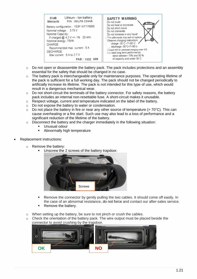
o Remove the battery: ▪ Unscrew the 2 screws of the battery trapdoor.
▪ Remove the connector by gently pulling the two cables. It should come off easily. In the case of an abnormal resistance, do not force and contact our after-sales service.
▪ Remove the battery.
o When setting up the battery, be sure to not pinch or crush the cables. o Check the orientation of the battery pack. The wire output must be placed beside the
connector to avoid crushing by the trapdoor.
Screws Screws
OK NO
1.22
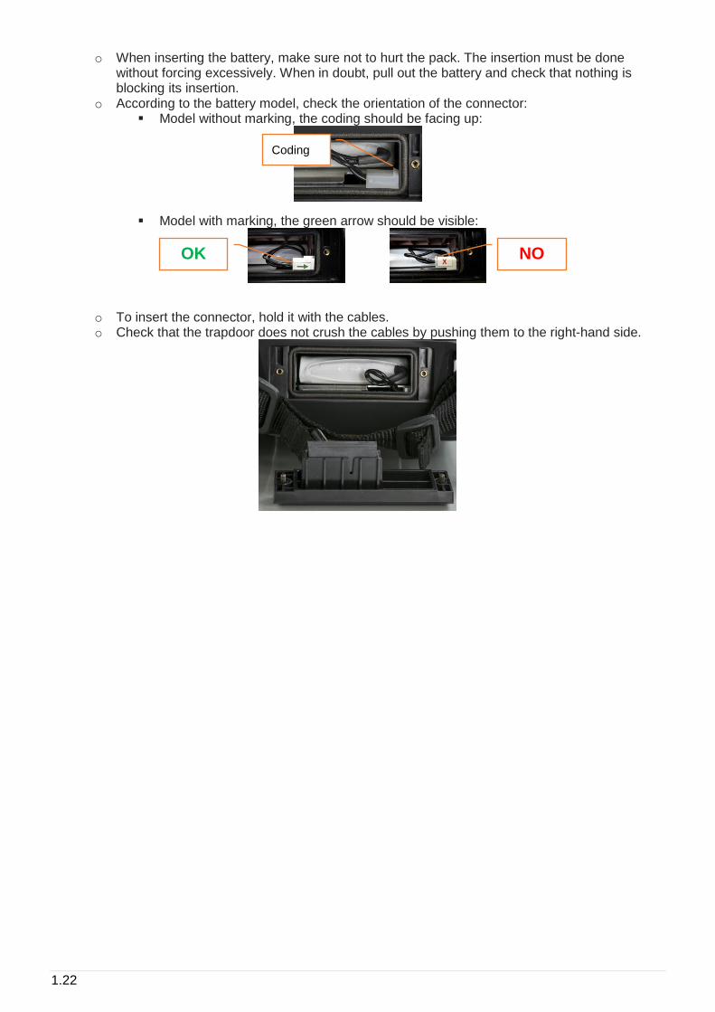
o When inserting the battery, make sure not to hurt the pack. The insertion must be done without forcing excessively. When in doubt, pull out the battery and check that nothing is blocking its insertion.
o According to the battery model, check the orientation of the connector: ▪ Model without marking, the coding should be facing up:
▪ Model with marking, the green arrow should be visible:
o To insert the connector, hold it with the cables. o Check that the trapdoor does not crush the cables by pushing them to the right-hand side.
Coding
OK NO
2.1
2 GENERAL SETTINGS
Access: Shortcuts panel > Settings
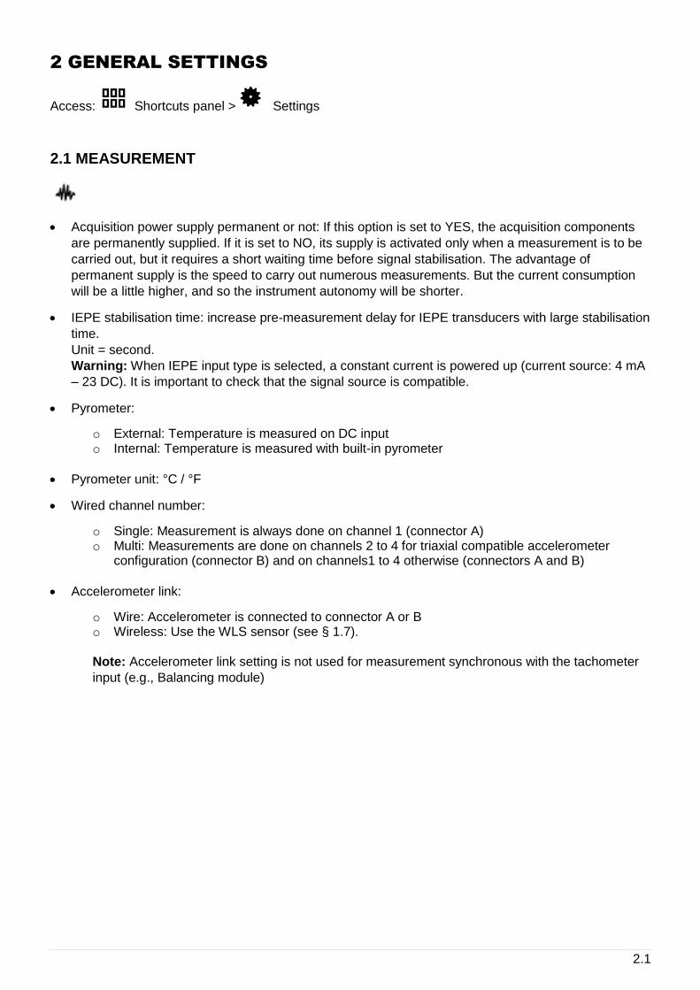
2.1 MEASUREMENT
• Acquisition power supply permanent or not: If this option is set to YES, the acquisition components
are permanently supplied. If it is set to NO, its supply is activated only when a measurement is to be
carried out, but it requires a short waiting time before signal stabilisation. The advantage of
permanent supply is the speed to carry out numerous measurements. But the current consumption
will be a little higher, and so the instrument autonomy will be shorter.
• IEPE stabilisation time: increase pre-measurement delay for IEPE transducers with large stabilisation
time.
Unit = second.
Warning: When IEPE input type is selected, a constant current is powered up (current source: 4 mA
– 23 DC). It is important to check that the signal source is compatible.
• Pyrometer:
o External: Temperature is measured on DC input o Internal: Temperature is measured with built-in pyrometer
• Pyrometer unit: °C / °F
• Wired channel number:
o Single: Measurement is always done on channel 1 (connector A) o Multi: Measurements are done on channels 2 to 4 for triaxial compatible accelerometer
configuration (connector B) and on channels1 to 4 otherwise (connectors A and B)
• Accelerometer link:
o Wire: Accelerometer is connected to connector A or B o Wireless: Use the WLS sensor (see § 1.7).
Note: Accelerometer link setting is not used for measurement synchronous with the tachometer
input (e.g., Balancing module)
2.2
2.2 WIRELESS SENSOR
Instructions for the first connection are presented in § 1.7
If the communication is bad or not possible, check following points:
• Check if the sensor is switched on and if the blue LED is continuously on (searching for connection)
or flashing (connected to an instrument)
• Check on FIXTURLASER SMC if Wi-Fi is enabled in:
Shortcuts > Setting > > Wi-Fi = enabled
• Check if FIXTURLASER SMC is set to work with a WLS sensor:
Shortcuts > Setting > > Accelerometer link = Wireless
• Check if the serial number of the sensor is that declared in FIXTURLASER SMC
Shortcuts > Setting > Wireless sensor
• Check with a shorter distance and no obstacle between the sensor and the instrument.
• If the connection is OK and the communication is bad, it may be due to another Wi-Fi network using
the same channel. You can try to use another one:
Shortcuts > Setting > Wireless sensor:
o Change the channel number only in case of bad quality transmission o Select in the list another channel o Keep the sensor powered near the device o Press "Save". o It will take a few seconds for the sensor to restart on the new channel.
You can also use the test function, it returns:
• The status of the test (Successful or Failed)
• WLS firmware version
• WLS hardware version
• Sensitivity for each of the 3 channels.
Default value for WLS auto switch-off is 10 minutes. If a longer time is needed, this screen can be used
to adjust it to 30 or 60 minutes.
2.3
2.3 TACHOMETER
First tab: Tachometer setup
• Adjustment of tachometer parameters:
o Input range: select the range according to the tachometer signal: +/-10V, 0/-24V, 0/+24V o Coupling:
▪ DC: default setting ▪ AC: a 0.3Hz high-pass filter is applied. This can be used if the DC component of
the signal is changing during measurement (for example: signal from a proximity probe during run-up / coast-down). If AC coupling is selected the automatic setup function is not accessible.
o Trigger slope: - (trigger on negative slope) or + (trigger on positive slope) o Trigger threshold: Value in Volt triggering the tacho input. It must be between -24 and +24
and within the selected input range. o Hysteresis: Value in Volt above (if slope=-) or under (if slope=+) trigger threshold to rearm
the system for the next triggering.
• Functions:
o Auto setup: Function to automatically adjust the trigger threshold and hysteresis. This function is not accessible if Coupling = AC.
o Test: When using this function, the power supply of the sensor is switched on. If the
setting is correct, you have green indicator , you must read a correct value of the rotation speed.
Second tab: display the signal. In case of difficult setting, it will help you adjust the parameters and check
the tachometer signal.
• Select first the duration in the list according the range of rotation speed.
• See signal: When using this function, the power supply of the sensor is switched on and the
signal is displayed.
From both tabs, to store the new setting exit with the function “Save” . “Cancel” exit with no
setting change.
2.4
2.4 SPECTRUM DISPLAY
Set the amplitude type, unit of spectrum and rotation speed:
• Spectrum amplitude: Linear, Exponential, dB
• Frequency and rotation speed unit: Hz, CPM, Order
Note: If ‘Order’ is selected, it is necessary to have machine rotation speed different from 0. In this
case, spectrum frequency axis is expressed in Hz.
• Acceleration, Velocity, Absolute displacement or Relative displacement amplitude: RMS, Peak or
Peak-to-Peak. Select the amplitude type displayed in the spectra for each type of magnitude.
• Acceleration, Velocity, Absolute displacement or Relative displacement unit: select the amplitude unit
displayed in the spectra for each type of magnitude.
• Spectrum conversion: None or converted to Acceleration, Velocity or Displacement. This setting is
used in the Supervisor module only.
• Envelope conversion: None or converted to Acceleration, Velocity or Displacement This setting is
used in the Supervisor module only.
• Hide 0Hz envelope spectrum: Select Yes to hide the 0Hz for envelope spectrum. This is necessary
mainly with a linear scale as the 0Hz line amplitude is usually greater than the other ones.
• Display overall value: None (no display), Uniform weighting, ISO6954 weighting
2.5 CAMERA
Set the access to the barcode reader and the camera. The access to the camera can be protected by
password (The protection is applied if you define a password on the last line of Settings >
About).
2.6 TOUCHSCREEN
• Screen brightness setting
• Screen calibration : It may be necessary to adjust the calibration. Click accurately in front of each
cross appearing on the screen with a soft and thin tip, then click once more on the screen. To store
the new setting, exit using function “Save” .
Note: If the calibration state does not allow using the touchscreen, it is possible to connect a mouse on
port G and use it to reach the calibration screen. Use then the touchscreen to calibrate it.
2.5
2.7 ABOUT
Display of:
• Product version: Main firmware, DSP, Hardware
• Instrument serial number
• Network addresses
• License information
Input of:
• License number to upgrade the instrument
Note: The License number is only accessible if this page is open from the home screen.
• Password to protect the access to some settings:
o In Camera: see § 2.5 o In Network: see § 2.9
2.8 DATE – LANGUAGE
Input of:
• Date: Format must be DD/MM/YYYY
• Time: Format must be HH:MM
• Time zone: Select your time zone in the list
• Daylight saving: Yes or No
• Language: Select in the list
• Set date and time format
• Date format: DD/MM/YYYY or MM/ DD/YYYY
• Time format: 12 or 24

2.6
2.9 NETWORK
Access by network (“Remote Display and Control” function)
• Password: To protect remote access from a PC (see § 1.12)
Remote access
• Server address: Input the address of the RDP server.
• Login: Username
• Password: Corresponding password
Ethernet configuration parameters: For more details, see § 1.8
• DHCP: Yes or No
• If DHCP is NO, you have access to:
o IP address o Mask o Gateway (optional) o DNS (optional)
Wi-Fi configuration parameters: for more details, see § 1.8
• Enabled: Yes or No
• Adhoc mode: Yes or No
• SSID: Input your SSID or use the function ‘Scan networks’ to list accessible ones.
• Default channel (for Adhoc mode only): 1, 5, 9, 13. Default value is 5.
• Authentication: Select in the list
• Encryption: Select in the list
• Key: Input encryption key
• DHCP: Yes or No
• If DHCP is NO, you have access to:
o IP address o Mask o Gateway (optional) o DNS (optional)
2.7
2.10 DATA MANAGEMENT
Used to delete all data of a particular module (Supervisor or Balancing) or clear all the data from the
instrument.
Reset supervisor: Delete all data of Supervisor module
Reset balancing: Delete all data of Balancing module
Full reset: Delete all data of the instrument
Reset setup: Return to instrument initial configuration
Data are definitively deleted.
Export log: Create an event log file in the ‘Export’ folder. This file can be used by Acoem
support for troubleshooting.
2.11 UPDATE FIRMWARE
It is first recommended to make a backup of the instrument memory.
For more details, see § 5.5
Note: This function is only accessible if this page is open from the home screen.
• Put update firmware (.czip file) on a USB memory key.
Note: The memory must have only one update file.
• Connect the system to its power supply.
• Plug the USB memory key in FIXTURLASER SMC connector G.
• Shortcuts > Setting > Update firmware
• Click on “Read USB memory”.
• Once the new firmware is detected click on “Update firmware”.
• Wait until the system restart.
2.8
2.12 AUTO TEST
Run tests on the main components of the instrument. This operation takes about 3 mn.
Note:
• This function is only accessible if this page is open from the home screen.
• Unplug the power supply
• Unplug all sensors (connector A, B, C and D)
• To check the WLS sensor, it is first necessary to connect it to the instrument (see § 1.7).
2.13 CALIBRATION
This screen gives information on the calibration of each channel.
Sensitivity can only be calibrated by authorised personnel.
An internal function ‘Offset calibration’ can be used to improve the accuracy of DC measurements.
Notes:
• This function is only accessible if this page is open from the home screen.
• For this operation, ambient temperature must be between 20 and 25°C.
2.14 BATTERY MANAGEMENT
• Setting of time in mn before standby and switch-off. You can set the value to 0 to disable the
automatic standby or switch-off.
• Possibility to disable Wi-Fi to extend the battery life.
3.1
3 SUPERVISOR MODULE
FIXTURLASER SMC Supervisor is a powerful vibration analysis tool accessible to all mechanics. It
offers immediate usability, giving a clear and accurate automatic diagnosis right in front of the machine
and based on a single measurement.
FIXTURLASER SMC offers all functions to manage the diagnostic of a machine in the field:
• Built in machine creation
• Built in automatic diagnostic
• Built in report generation (word file)
Note: It is recommended to first read the printed Quick tips manual delivered with the device and
available on the USB Stick.
This chapter will provide detailed information on the use of the supervisor module.
3.1 CREATE A MACHINE
Select the template from the device memory
To create a new machine for diagnostic purposes:
• Go into the supervisor module.
• Click on “Import” , and select the template machine that best correspond to your machine. E.g.
PumpBB-GB1 for a Motor driving a Pump between bearings with a 1 stage gearbox transmission.
Notes:
• Templates are available in multiple languages on the USB stick delivered with the device. To replace
the current templates by the ones corresponding to the desired language, proceed to the following:
o Connect the FIXTURLASER SMC connector H to a USB port of the PC.
o From the home screen, select the “Communication” module: o On the PC: Copy the templates in your language from the USB stick o Paste them on the FIXTURLASER SMC “Import” Folder to replace the existing ones.
• For a machine with Belt, Pulley or Chain transmission, select the Belt template.
Modify the machine characteristics
Click on the button Modify to adjust the machine characteristics:
• Name
• Information collected from the name plate or process: Power, Speed
• Type of mounting: Rigid or Flexible.
• Speed reference shaft (on which is measured the rotation speed): motor or driven component
• For machine with transmissions (belt, pulley, chain, gearboxes): information on the multiplication
factor.
3.2
The modifications can be saved on the existing machine or duplicated into a new machine.
3.2 MAKE MEASUREMENTS
Machine list screen
This screen lists all the machines loaded in the instrument. On the top of the screen you can select how
to sort the machines as follows:
• Name
• Number of points
• Completed percentage
• Measurement date
• Loading date
• Downloading date
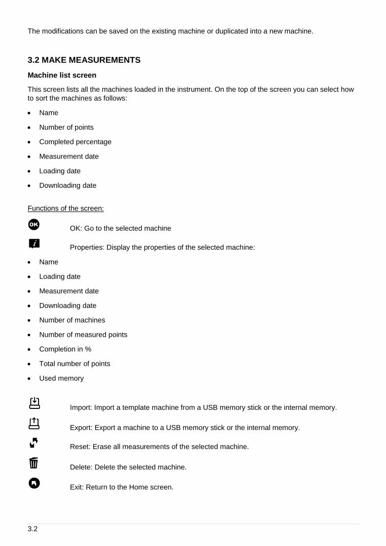
Functions of the screen:
OK: Go to the selected machine
Properties: Display the properties of the selected machine:
• Name
• Loading date
• Measurement date
• Downloading date
• Number of machines
• Number of measured points
• Completion in %
• Total number of points
• Used memory
Import: Import a template machine from a USB memory stick or the internal memory.
Export: Export a machine to a USB memory stick or the internal memory.
Reset: Erase all measurements of the selected machine.
Delete: Delete the selected machine.
Exit: Return to the Home screen.

3.3
Measurement screen
This screen displays the points and the list of measurements to be done if the function Acquisition is
used.
The group of point displayed together depends on:
• The instrument channel number
• The setting of the point done on the PC
• The setting of the instrument
Functions of the screen:
Acquisition: See § 3.6.
Previous: Go to previous group of points
Next: Go to next group of points.
See: See the selected measurement. For more details, see § 3.7.
Note: Not accessible from the ‘Machine view’. If the measurement is not done, it will show
live acquisition.
/ Switch ‘Machine view’ and ‘Measurement list mode’
Diagnosis: Get the machine diagnosis directly after your measurement.
Delete: Delete all the measurement of the group of points.
Machines: Return to the list of machines.
Functions of the screen using the shortcuts :
Inspection picture: See § 3.9.
Inspection note: See § 3.9.
Inspection vocal note: See § 3.9.
Listen sensor signal: See § 1.10.
Use the pyrometer for temperature measurement: See § 3.6.
Use the stroboscope for rotation speed measurement: See § 3.6.
3.4
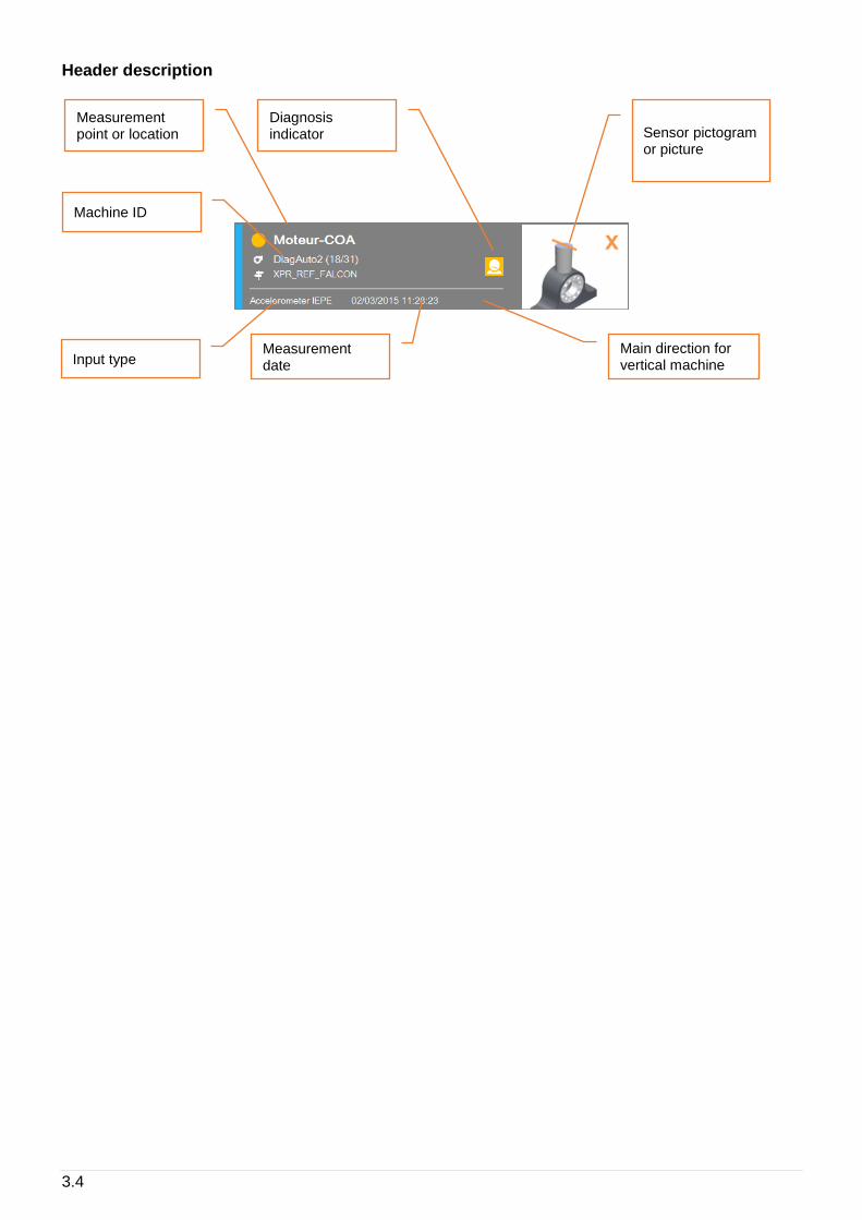
Header description
Machine ID
Measurement point or location
Input type Measurement date
Main direction for vertical machine
Diagnosis indicator Sensor pictogram
or picture
3.5
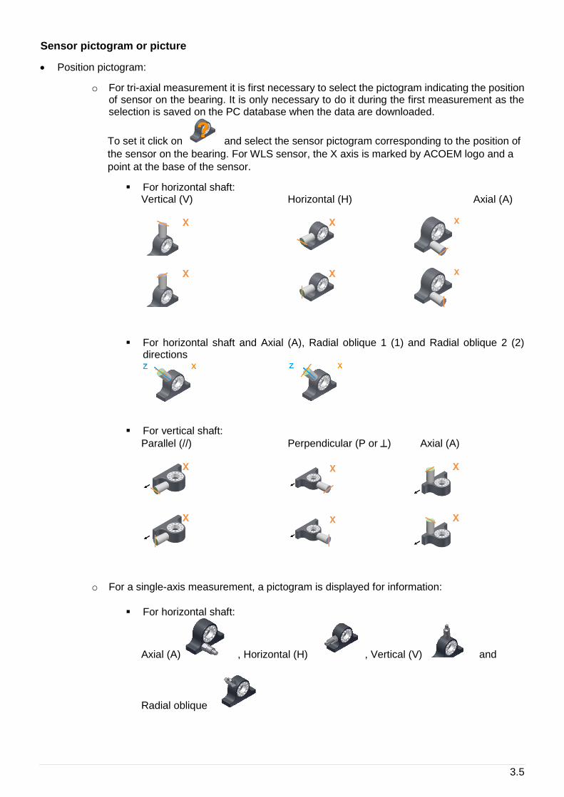
Sensor pictogram or picture
• Position pictogram:
o For tri-axial measurement it is first necessary to select the pictogram indicating the position of sensor on the bearing. It is only necessary to do it during the first measurement as the selection is saved on the PC database when the data are downloaded.
To set it click on and select the sensor pictogram corresponding to the position of
the sensor on the bearing. For WLS sensor, the X axis is marked by ACOEM logo and a
point at the base of the sensor.
▪ For horizontal shaft: Vertical (V) Horizontal (H) Axial (A)
▪ For horizontal shaft and Axial (A), Radial oblique 1 (1) and Radial oblique 2 (2) directions
▪ For vertical shaft:
Parallel (//) Perpendicular (P or ) Axial (A)
o For a single-axis measurement, a pictogram is displayed for information:
▪ For horizontal shaft:
Axial (A) , Horizontal (H) , Vertical (V) and
Radial oblique
3.6
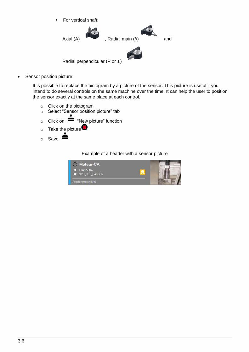
▪ For vertical shaft:
Axial (A) , Radial main (//) and
Radial perpendicular (P or )
• Sensor position picture:
It is possible to replace the pictogram by a picture of the sensor. This picture is useful if you
intend to do several controls on the same machine over the time. It can help the user to position
the sensor exactly at the same place at each control.
o Click on the pictogram o Select “Sensor position picture” tab
o Click on “New picture” function
o Take the picture
o Save
Example of a header with a sensor picture
3.7
Acquisition screen
The instrument takes in one shot all measurements with the same input type for all the points grouped
together.
The channel association rules are explained in § 1.5.
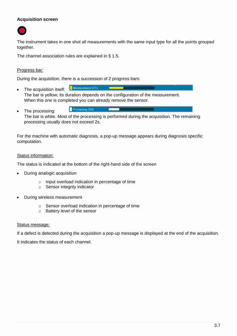
Progress bar:
During the acquisition, there is a succession of 2 progress bars:
• The acquisition itself:
The bar is yellow; its duration depends on the configuration of the measurement.
When this one is completed you can already remove the sensor.
• The processing:
The bar is white. Most of the processing is performed during the acquisition. The remaining
processing usually does not exceed 2s.
For the machine with automatic diagnosis, a pop-up message appears during diagnosis specific
computation.
Status information:
The status is indicated at the bottom of the right-hand side of the screen
• During analogic acquisition
o Input overload indication in percentage of time o Sensor integrity indicator
• During wireless measurement
o Sensor overload indication in percentage of time o Battery level of the sensor
Status message:
If a defect is detected during the acquisition a pop-up message is displayed at the end of the acquisition.
It indicates the status of each channel.

3.8
3.3 DISPLAY VIBRATION MEASUREMENTS
This function displays the result of the selected measurement. If acquisition is not yet performed, it
displays directly the live values.
There are 2 types of display:
• Overall levels
• Low frequency Spectrum (used for rotation speed adjustment)
For the spectrum, a first click on a curve selects it as the current one, a 2nd click sets a cursor. The
cursor is automatically positioned on the maximum of the curve around the click area. Then it can be
moved with functions and .
Functions of the screen:
Next measurement: go directly to the next measurement of the measurement list screen.
Previous measurement: go directly to the previous measurement of the measurement list
screen.
Live measurement: switch to live measurement mode. return to stored mode. Live
mode is directly selected if there is no acquisition stored. Acquisition can be started
from the live mode.
Full screen: display the selected curve full screen. return to to the multi curve display.
Cursor type selection
• Single (spectrum and time-wave)
Indications:
• At the bottom: Frequency
• At the top: Amplitude
• Double (spectrum and time-wave)
Select active cursor
Indications:
• At the bottom: The distance between the 2 cursors
• At the top: o Spectrum: RMS or equivalent value between the 2 cursors o Time-wave: Amplitude
• Harmonic
The fundamental cursor is automatically adjusted on the true frequency of a maximun by
interpolation. Harmonic frequencies in coincindence with a maximum are marked by a sign.
Indications:
• At the bottom: Fundamental frequency
• At the top: Amplitude at the fundamental frequency
3.9
• Side band
The central cursor and the first side band cursor are automatically adjusted on the true frequency
of a maximun by interpolation. Side band frequencies in coincindence with a maximum are
marked by a sign.
Select active cursor, central frequency or side band.
Indications:
• At the bottom: Central frequency and distance
• At the top: Amplitude at the central frequency
Zoom +: Apply a zoom factor 2 around the cursor position.
Zoom -: Return back to previous zoom factor
Setting display: Change the setting of the display:
o Scale: Linear, logarithmic or dB (for spectrum display only) o Framing:
▪ Multi: The limits of Y axis are the same for all the curves ▪ Single: The limits of Y axis are computed independently for each curve
o Unit: Acceleration, velocity or displacement (for spectrum display only)
Return: Return back to measurement list screen.
Functions of the screen using the shortcuts :
Listen sensor signal: See § 1.10.
Use the stroboscope for rotation speed measurement: See § 1.10 (for spectrum display
only).
3.10
Take a temperature reading on a bearing
Temperature measurement using the pyrometer
For the pyrometer please read the safety instructions delivered with the instrument (printed and on the
USB STICK)
To make a measurement of the bearing temperature, call the pyrometer from the shortcut panel .
• A warning is displayed before switching on the laser beam. Make sure that nobody stands in its
direction.
• Aim the beam at the target (Warning: Due to the distance between the pyrometer cell and the laser
source the beam is decentred by 3 cm on the right-hand side of the target).
• Press to start acquisition.
• The temperature can be recorded and added to the text notes, printed in the report.
3.11
3.4 ADJUST THE ROTATION SPEED WITH THE STROBE LIGHT
Rotation speed using built-in stroboscope.
For the stroboscope please see the safety instructions delivered with the instrument (printed and on the
USB STICK)
The accuracy of the rotation speed input into the system will significantly affect the reliability of the
diagnostic result. With Fixturlaser SMC, it possible to measure the rotation speed using the built-in
stroboscope. (For more details on the use of the strobe light, see § 1.10).
To manually make a measurement of the rotation speed, call the strobe light from the shortcut panel.
Important note: The strobe light must be called from a measurement point belonging to the speed
reference shat, as defined in the machine properties, see § 3.1.
For a quick and efficient measurement, it is recommended to adjust it directly from the Low Frequency
“Spectrum LF” present in the measurement list:
• Display the Spectrum LF
• Use the Harmonic Cursor
• Roughly point to the peak that correspond to the expected rotation speed (e.g. 25 Hz), as indicated
on the name plate of the motor (1 Hz = 60 RPM)
• Make sure that the harmonics are detected automatically by the harmonic cursors.
• Call the strobe from the shortcut panel
• Adjust with the arrows if needed, and save.
• If you already displayed the diagnostic before, you must reprocess it by clicking again on the
diagnostic button.
3.12
3.5 RUN AUTOMATIC DIAGNOSIS
This function gives directly the machine diagnosis instantly after your measurement.
The diagnosis information is:
• A pictogram giving the general status of the machine:
The machine is good
The machine is still acceptable
The machine is not acceptable
• The rotation frequency and the number of measurement points used to compute the diagnosis
• The comment concerning the general status
• The list of detected defects with for each one:
o The type
o The severity:
Slight defect
Defect to be monitored
Defect to be corrected
o The confidence of the diagnosis: * Suspected
** Likely
*** Quite likely
**** Certain
Functions of the screen:
Next: see directly the diagnosis of the next machine.
Previous: see directly the diagnosis of the previous machine.
Return: return back to measurement list screen.
Defect: see the details of the selected defect. The information on the defect is:
• Defect type
• Its severity (see above)
• The confidence (see above)
• The list of component or location of the machine where the defect is visible with for each one the severity.
3.13
Functions of the “Defect detail” screen:
Next: go directly to the next defect.
Previous: go directly to the defect.
Return: return back to Diagnosis screen.
3.6 ADD COMMENT TO THE DIAGNOSIS
Functions of the screen using the shortcuts:
It is possible to add inspection information using functions accessible through the shortcuts panel:
Inspection picture: See also § 1.10.
The pictures are downloaded as an attachment to the measurement date of the machine and visible in
the printable REPORT.
Inspection note: See also § 1.10.
The text inspection note is printed automatically in the reports.
Inspection vocal note: See § 1.10.
The vocal inspection note remains available in FIXTURLASER SMC for the end user as long as the
measurement is not deleted, but also automatically sent to a remote expert if a request for assistance is
made (see § 3.12).
3.7 GENERATE REPORT
The report is generated from the diagnostic screen with function .
If a USB memory stick is plugged in connector G, the report is generated on it in a folder named Export.
Otherwise the report is stored in the instrument internal memory in an export folder as well.
Customized report
Reports are based on templates. The templates are available on the USB STICK supplied with the
instrument. There is one template per language.
The format is docx. To customize a template, use MS Word. You can change the format, add your
company logo and remove unnecessary information.
The name of customised templates must be “template expertise.docx.
The template must be copied to the instrument internal memory in folder “‘expertise_report_templates”.

3.14
3.8 COLLECT THE REPORT FROM A COMPUTER
On FIXTURLASER SMC:
• Connect connector H to a USB port of the PC.
• From the home screen, select the “Communication” module:
On the PC:
Wait for the FIXTURLASER SMC to be displayed as an external drive on the computer. It usually takes
about 30s maximum. If it takes more time, it may be due to a previous bad disconnection. To solve the
problem, you can:
• Try another USB port of your computer
• Reboot the SMC device or the computer.
Once the FIXTURLASER SMC is detected, go into the Export folder to retrieve your reports.
Note: if an audio comment was recorded, it will be present next to the related report.
4.1
4 BALANCING MODULE
The Balancing module enables "in situ" balancing of a rotating machine. This means that it is possible to
balance the machine's rotor within its own bearings, without having to dismantle it completely and
without resorting to a balancing rig.
FIXTURLASER SMC is a universal tool that can be adapted to the entire base of machines to be
balanced on site, regardless of the size and complexity of the rotors, by managing up to 4 balancing
planes:
• Management of accelerometers, velocimeters, proximity probes (run-out compensation)
• Simultaneous measurements on several vibration channels and a tachometer
• Rotation speeds ranging from 12 to 280,000 CPM (indicated in Hz or CPM)
• Management of metric and imperial units.
Simple to use, FIXTURLASER SMC supports the operator through every task and controls the reliability
of the balancing results. The user is guided through the user-friendly visual interface, step by step, to
define the machine, automatically configure the tachometer, define the trial weights and corrective
weights, and perform measurements.
The principle is to add known weights named “trial weights” to a rotor and to assess the resulting
variations. This enables the influence matrix to be assessed, as well as the complete set of coefficients
characterizing the relationships between the unbalance and the vibrations that it generates. It is then
easy to calculate the unbalance generated by the vibration measured on the instrument and, as a result,
the weights that can compensate the said unbalance.
Two cases may occur:
• You are balancing the machine for the first time, and you do not know the influence matrix yet, it is
then required to make several measurement sets (or runs) with various additional balancing weights
• You have already balanced the machine and just a single additional trim run is then required: see §
4.13
The next chapter gives a general view of different steps of the balancing operations.
Note: it is recommended to first read the printed Quick tip manual delivered with the device and available
on the USB Stick.
This chapter will provide detailed information on the use of the balancing module.
4.2
4.1 FOLDER LIST
This creates a management folder used to sort balancing tests. A folder can be used to store, for
example, tests on the same machine or all balancing done for a customer.
Functions of the screen:
Go to selected folder: see § 4.3.
Create a new folder in the list.
Change the name of selected folder.
Delete selected folder.
Return to Home screen.
4.2 BALANCING LIST
This screen displays the list of balancing tests of a folder. If a measurement has been done the list
shows also the last measurement date.
Functions of the screen:
Go to selected balancing test.
Create a new balancing test in the list.
Change the name of selected balancing test.
Create a report of selected balancing test: see § 4.13.
Copy selected balancing test in the clipboard.
Paste in the list the balancing test from the clipboard. Only the setup is pasted. No
measurement or result is copied.
Reset: erase all measurements and results of selected balancing test.
Delete selected balancing test.
4.3
4.3 INSTALLING THE EQUIPMENT
To perform the balancing measurements, you should have a triggering device and at least one vibration
sensor available. Take care to not change the position of the sensors during the entire balancing
process.
Vibration sensor
Note: As phase measurement is required, Balancing module cannot be used with the WLS Sensor. This
module does not take in account the setting: Accelerometer link: Wire or Wireless (see § 2.1).
It is possible to use the following type of sensor:
• Accelerometer
• Velocimeter
• Proximity probe
It is advisable to locate the measurement points on the bearings. Indeed, vibrations created by the rotor
are transmitted to the frame at this point. The sensor (accelerometer, a velocimeter) must be fixed onto
the machine (with a cementing screw, stud or a magnet) in order to obtain a proper connection and a
well-determined position for the sensor.
Several measurement points may be needed. The required number of points is related to the type of
machine to be balanced.
Connection:
• 1 channel balancing: vibration sensor is connected on channel 1 (Connector A)
• 2 channel balancing:
o Point 1 is connected on channel 1 (Connector A) o Point 2 is connected on channel 2 (Connector B)
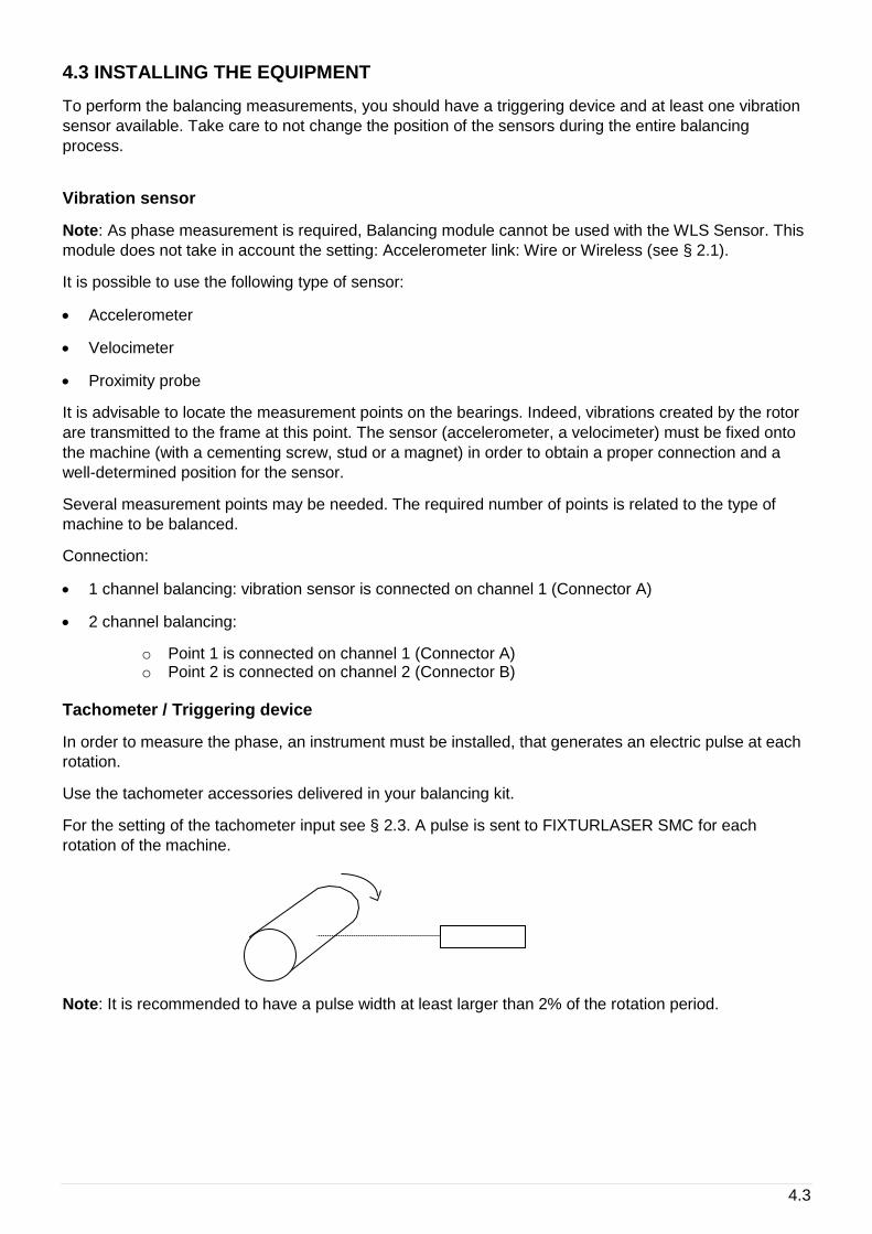
Tachometer / Triggering device
In order to measure the phase, an instrument must be installed, that generates an electric pulse at each
rotation.
Use the tachometer accessories delivered in your balancing kit.
For the setting of the tachometer input see § 2.3. A pulse is sent to FIXTURLASER SMC for each
rotation of the machine.
Note: It is recommended to have a pulse width at least larger than 2% of the rotation period.

4.4
4.4 SETUP
This screen includes 4 tabs. They are used to define the balancing and the type of measurement used to
perform the balancing process.
Values can be directly modified. If some modifications have been made, a confirmation message to save
them or not is asked before going to another screen.
Once the setup is completed, it is possible to:
Go to the next step: Run out measurement if you are using proximity probes (see § 4.6) or
Free run in other cases (see § 4.7)
Go to the steps browser to reach directly any other accessible step (see § 4.11)
Exit: return to balancing test list (see § 4.3)
Notes:
• If some modifications have been made, a confirmation message to save them or not is asked before
going to another screen.
When a measurement is already done, it is normal that some setting cannot be modified.
4.5
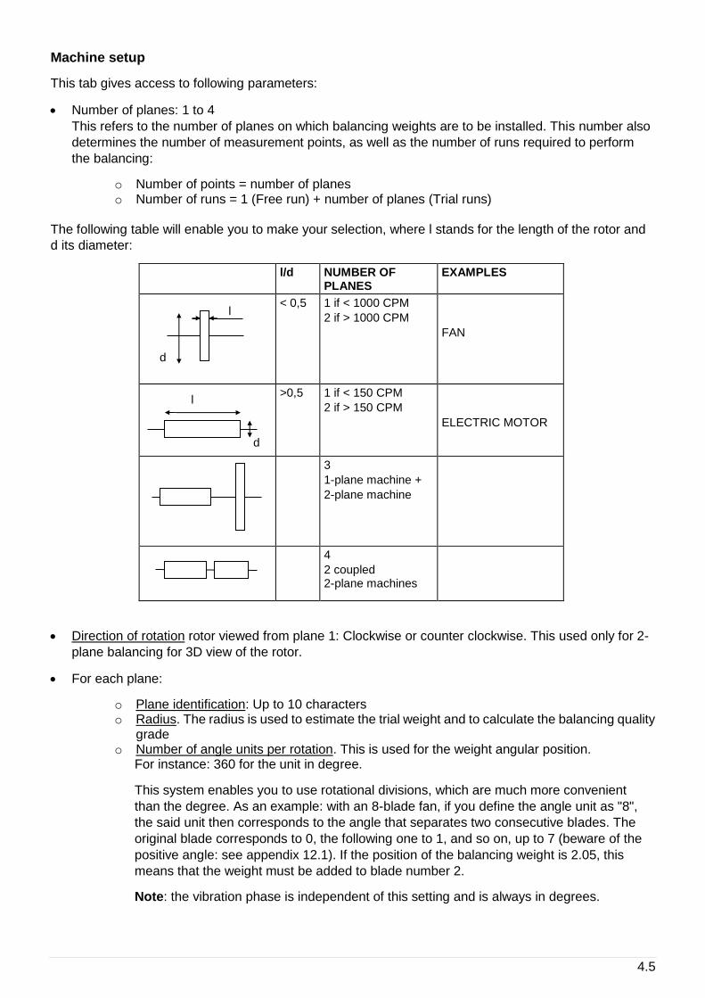
Machine setup
This tab gives access to following parameters:
• Number of planes: 1 to 4
This refers to the number of planes on which balancing weights are to be installed. This number also
determines the number of measurement points, as well as the number of runs required to perform
the balancing:
o Number of points = number of planes o Number of runs = 1 (Free run) + number of planes (Trial runs)
The following table will enable you to make your selection, where l stands for the length of the rotor and
d its diameter:
l/d NUMBER OF PLANES
EXAMPLES
< 0,5 1 if < 1000 CPM
2 if > 1000 CPM
FAN
>0,5 1 if < 150 CPM
2 if > 150 CPM
ELECTRIC MOTOR
3
1-plane machine +
2-plane machine
4
2 coupled 2-plane machines
• Direction of rotation rotor viewed from plane 1: Clockwise or counter clockwise. This used only for 2-
plane balancing for 3D view of the rotor.
• For each plane:
o Plane identification: Up to 10 characters o Radius. The radius is used to estimate the trial weight and to calculate the balancing quality
grade o Number of angle units per rotation. This is used for the weight angular position.
For instance: 360 for the unit in degree.
This system enables you to use rotational divisions, which are much more convenient
than the degree. As an example: with an 8-blade fan, if you define the angle unit as "8",
the said unit then corresponds to the angle that separates two consecutive blades. The
original blade corresponds to 0, the following one to 1, and so on, up to 7 (beware of the
positive angle: see appendix 12.1). If the position of the balancing weight is 2.05, this
means that the weight must be added to blade number 2.
Note: the vibration phase is independent of this setting and is always in degrees.
l
d
l
d
4.6
Measurement setup
This tab gives access to following parameters:
• Number of channels: 1 or 2. This value is only accessible for a 2-plane balancing. If 1 is selected at
each run, each point is measured one after the other one. In all other cases, the number of channels
is equal to the number of planes.
• Number of average: 1 to 256. Advised value: 8.
Measurements are obtained by averaging several successive acquisitions. This enables, on one
hand, a statistically representative result to be obtained in the case where the vibration resulting from
the unbalance is disturbed by other factors, and on the other hand, the measurement is combined
with two values resulting from the averaging (dispersion in measurement and rotation speed), which
enables the level and the nature of these perturbations to be assessed. If dispersion is important, it is
recommended to increase the number of averages.
• Input type: select the item corresponding to the used sensor type. The list is:
o Accelerometer IEPE o Accelerometer AC o Velocimeter IEPE o Velocimeter AC o Proximity probe
• Input unit:
o For accelerometer: g, m/s2 o For velocimeter: in/s, mm/s o For displacement AC: mils, µm
• Measured parameter:
o For accelerometer: Acceleration, Velocity, Absolute displacement o For velocimeter: Velocity, Absolute displacement o For proximity probe: Relative displacement
• Parameter unit:
o Acceleration: g, m/s2 o Velocity: in/s, mm/s o Absolute or relative displacement: mils, µm
• Sensitivity for each measurement point in mV/input unit
4.7
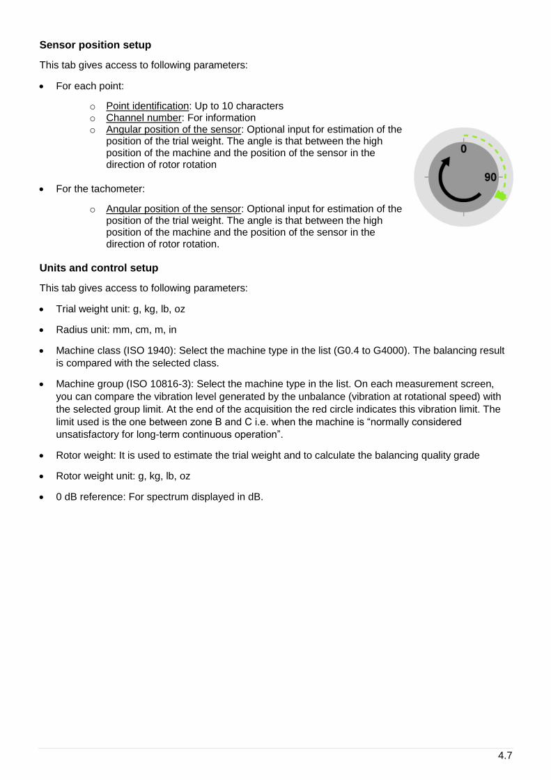
Sensor position setup
This tab gives access to following parameters:
• For each point:
o Point identification: Up to 10 characters o Channel number: For information o Angular position of the sensor: Optional input for estimation of the
position of the trial weight. The angle is that between the high position of the machine and the position of the sensor in the direction of rotor rotation
• For the tachometer:
o Angular position of the sensor: Optional input for estimation of the position of the trial weight. The angle is that between the high position of the machine and the position of the sensor in the direction of rotor rotation.
Units and control setup
This tab gives access to following parameters:
• Trial weight unit: g, kg, lb, oz
• Radius unit: mm, cm, m, in
• Machine class (ISO 1940): Select the machine type in the list (G0.4 to G4000). The balancing result
is compared with the selected class.
• Machine group (ISO 10816-3): Select the machine type in the list. On each measurement screen,
you can compare the vibration level generated by the unbalance (vibration at rotational speed) with
the selected group limit. At the end of the acquisition the red circle indicates this vibration limit. The
limit used is the one between zone B and C i.e. when the machine is “normally considered
unsatisfactory for long-term continuous operation”.
• Rotor weight: It is used to estimate the trial weight and to calculate the balancing quality grade
• Rotor weight unit: g, kg, lb, oz
• 0 dB reference: For spectrum displayed in dB.
4.8
4.5 RUN-OUT MEASUREMENT
Note: This step is only accessible if the input type is “proximity probe”.
Definition of the run-out
The proximity sensors operating with eddy current probes are sensitive to irregularities of the surface
pointed by the sensor (shape, cracks, carbon inclusions, magnetized areas, etc.).
The signal provided by the Run-Out is at the rotation frequency of the machine and is thus merged with
the unbalance phenomenon.
If the Run-Out level is high, it must be taken into account, otherwise the values of the weights calculated
by the program will compensate the Run-Out signal (which has no effect on the machine) by an
unbalance (noxious effect on the machine).
Measurement of the Run-Out
The run-out can be measured while the machine is rotating very slowly. In fact, the run-out amplitude
remains unchanged when the rotation speed varies, whereas the unbalance effects are negligible at low
speed, and make their presence felt only when the speed increases.
Run-Out Measurement screen
The screen is similar to any other measurement screen, see next chapter for more details. This
measurement must be performed at the lowest possible speed.
Run-Out compensation
On the result step (Balancing or Trim), there is an option to compute the balancing weight with the Run-
out compensation.
4.6 FREE RUN
After installing the vibration sensor and the tachometer, run the machine at its usual speed. This run
measures the vibration at the rotation speed.
Functions of the screen:
Tachometer setup.
Note: The free run is usually the first measurement, use this function to set tacho
parameters (see § 2.3).
Acquisition: Wait for the machine to reach its steady state before starting the acquisition.
During the acquisition, a dot is displayed for each average. If dots are not all in the same
place, it shows that vibration dispersion may be too high. At the end of the acquisition the
red circle indicates the vibration limit corresponding to the ISO 10816-3 selected in the
setup.
Note: If it is a 2-plane balancing done using only one channel, click on the circle to select
the measured point.
Spectrum measurement without tacho: If there is no tacho on the machine, it is possible to
use this function to measure the spectrum and check if the machine is unbalanced. If an
important level is seen at rotation speed, you can then stop the machine, install the tacho
and proceed to balance it.
4.9
See spectrum.
Note: It is important to display the spectrum after the free run to confirm that the problem of
the machine is unbalance. The amplitude at the rotation must be larger than the other
ones. If not there are certainly other actions to do on the machine before balance it.
Quality of measurement: Gives access to the dispersion of vibration and rotation speed.
FIXTURLASER SMC includes an automatic analysis of the measurement. If an abnormal
event is detected the measurement screen display an alert pictogram ( ). If it is displayed
the quality screen gives additional information:
• Rotational speed unsteady during measurement
• Measurement dispersion is important.
For the other runs, there are also following messages:
• Trial weight insufficient: Measurements are too close from a previous one
• Rotational speed too far from the free run’s one
Go to previous step
Go to next step
Go to the steps browser to reach directly any other accessible step (see § 4.11)
Exit: return to balancing test list (see § 4.3)
Symbols used on measurement screen:
• Free run:
• Trial runs: , , …
• Balancing run:
• Trim runs: , , …
Note: 3 and 4-plane balancing is displayed in tabular mode only.
T1 T2
4.10
4.7 TRIAL RUN
Known unbalance is added on the rotor to compute the relation between measured vibration and rotor
unbalance. The number of trial runs is equal to the number of balancing planes.
Trial run definition
You must indicate the value of the weight and its angular position in each of the balancing planes.
Carefully observe the angle convention (direction of rotation = positive direction of angles). The angle
unit defined in the setup is recalled on the left-hand side of the input field. Generally, the first trial run is
performed one with the weight in plane 1, the second one with the weight in plane 2 and so on until all
the runs are completed.
Go to previous step
Go to next step.
See the rotor from the other side (for 1 or 2-plane balancing)
Trial weight estimation:
This function estimates a trial weight value to avoid adding a too high unbalance which could damage
the machine.
The result is only indicative. It is not required to add a weight exactly identical to the calculated value.
The trial weight must at least change the vibration amplitude by 20% or its phase by 20 degrees. If the
weight is not sufficient, a warning indicates it after the trial run measurement. In this case, it is
recommended to increase the weight value and to repeat the measurement.
Principle:
A usually adopted method involves the calculation of a weight m, which generates a force equivalent to
one tenth of the weight of the rotor to avoid adding too high an unbalance, which could damage the
machine.
mN
xr
xM
xx
xV
1 1
109 81 3600
41
2 2
,
With:
r radius at which the trial weight m is located
M weight of the rotor in kg
V rotation speed in CPM
N number of planes
m trial weight in kg
If the sensor position has been defined in the setup and if the dephasing due the bearing structure can
be evaluated, this tool also gives an estimation of the angular position in opposition with the unbalance
to avoid increasing the vibration.
4.11
Note:
• the origin of angular position on the rotor must be in front of the triggering position (the reflective
adhesive tape for instance)
• for a measurement with accelerometer or velocimeter, there is an additional error for low-speed
machine (< 300 CPM) due to the phase shift between signal input and tachometer input.
Equivalent weight:
Tool to compute the weight equivalent to 3 weights W1, W2 and W3 positioned on the
selected plane
Go to the steps browser to reach directly any other accessible step (see § 4.11)
Exit: return to balancing test list (see § 4.3)
Symbols used on definition screen:
• Trial runs: , , …
• Balancing run:
• Trim runs: , , …
Note:
• Negative weight is symbolized by a white square. Example:
• Weights of other runs are symbolized with fine borders and parentheses:
• 3 and 4-plane balancing is displayed in tabular mode only
Trial run measurement
Once the trial weights are installed, restart the machine.
The operating mode is the same as for free run: see § 4.7.
1 2
B
T1
T2
2
(2)

4.12
4.8 BALANCING RESULT
Result
After the last trial run, the instrument displays computed balancing weights. It is possible to select:
• The reference run: Indicate the run to which balancing weights are to be added. Generally, it is either
the free run (run without any trial weight), or the last run (run with all trial weights) when it is difficult
or impossible to remove trial weight.
• Run-out: Yes or No. For measurement done with proximity probe only: see § 4.6.
Go to previous step
Go to next step
See the rotor from the other side (for 2-plane balancing only)
Go to the steps browser to reach directly any other accessible step (see § 4.11)
Exit: return to balancing test list (see § 4.3)
Balancing run definition
The screen is initialized with the computed balancing weights of the previous step.
It is necessary to input the value and angular position weight effectively installed on the rotor.
Tools for balancing weight definition:
Equivalent weight: 2 tools are available:
• Split: If the weight cannot be installed at the required position, it is possible to choose 2 other positions on both sides. This tool computes weights to be installed at these 2 positions.
• Combination: This tool let you combine 1 or 2 weights already present (W2, W3) with the correction weight (C), to replace them by a single weight (M)
The equivalent correction will be automatically used in the weights definition screen.
Simulation: show the theoretical vibration expected for the set of defined weights.
Balancing run measurement
Once the balancing weights installed, start again the machine and measure to control the vibration level.
The use is the same as for free run: see § 4.7.
Go to next step to display the balancing quality grade.
4.13
4.9 TRIM STEPS
The trim steps are used to iterate up to 8 additional measurements used to improve the result of the
balancing.
Trim result
This screen shows:
• The balancing quality grade estimation.
Notes:
o To display the quality, it is necessary to have the rotor weight and radius not equal to 0. o The quality is computed only for 1 or 2 plane balancing.
• The weights to add on the rotor to try improve the balancing quality.
Trim definition
The screen is initialized with the computed trim weights of the previous step.
It is necessary to input the value and angular position weight effectively installed on the rotor.
The operating mode is the same as for balancing run: see § 4.9.
Trim measurement
Once the trim weights installed, start again the machine and measure to control the vibration level.
The operating mode is the same as for free run: see § 4.7.
Go to next step to display the new balancing quality grade.
4.10 STEPS BROWSER
This screen list all the steps of the balancing process and gives access to any steps already completed.
A step is not accessible if the previous one is not done.
4.14
4.11 ONE RUN BALANCING
If a balancing has already been done on a machine, it is possible to perform a balancing procedure with
only one run.
It is important that this new run is performed under the same conditions as the initial runs, i.e.:
• The rotation mark in the same angular location on the rotor,
• The same angle origin on the rotor,
• The same rotation speed,
• The same location for sensors,
• The same type of measurement equipment,
• The same instrument setting.
In the first instance, start the machine and take a measurement for each point, using the last trim
Measurement option. The trim weight calculation can then be requested.
If this method does not provide good results, the complete balancing must be performed again. This
means that the machines’ influence matrix has changed. This can come either from changes in the
conditions under which measurements are taken, or from an internal modification of the machine (wear,
suspension ageing, dismantling and assembling with new seals or different tightening rates).
4.15
4.12 REPORT
Picture and comment
Before generating the report, you can document the balancing with pictures and a comment. From any
step of the balancing, from the shortcut panel , you can use following functions:
Add a picture. You can take up to 6 pictures to document the report: global picture of the
machine, sensor installation, weight installation… (see § 1.10)
Add a comment. This comment appears in the balancing report (see § 1.10)
Generate report
The report is generated from the balancing list screen (see § 4.3) with function .
If a USB memory stick is plugged in connector G, the report is generated on it in a folder named
“Export”. Otherwise the report is stored in the instrument internal memory.
Customized report
Reports are based on templates. The templates are available on the USB STICK supplied with the
instrument. There is one template per language and per number of balancing planes.
The format is docx. To customize a template, use MS Word. You can change the format, add your
company logo and remove unnecessary information.
The name of customised templates must be “template_N-plane.docx”, where N is 1, 2, 3 or 4 and equal
to the number of balancing planes.
The template must be copied to the instrument internal memory in folder “‘balancing_report_templates”.

4.16
5.1
5 MAINTENANCE
5.1 RESET
Open the connector trapdoor. The reset button is in front of the small hole. Press it with a thin tip (a
paperclip for example) during 5 or 6 seconds. The instrument restarts on the home screen. No data are
deleted with this operation.
5.2 CLEANING
To clean up the instrument, use only soft products (lightly soaped water). For delicate surfaces (screen,
pyrometer, tachometer and laser lenses), use only clean compressed air to remove particles. If needed,
gently wipe the surface using a soft, damp cloth.
5.3 CALIBRATION
To provide best auto diagnostic results, calibration of the instrument is highly recommended at least
every 2 year. Please contact your sales representative for more information on calibration services.
5.4 BACKUP OF INSTRUMENT MEMORY
Connect first the instrument to the PC (see § 1.8). You can now copy the data from the instrument to
your PC for backup purpose.
5.5 INSTRUMENT FIRMWARE UPDATE
See § 2.11
5.6 WLS SENSOR FIRMWARE UPDATE
• SMC must be switch off during this operation
• Switch on the WLS sensor: press on/off for 2s
• Connect it to a PC using the USB cable
• Wait until its drive is visible from the PC
• Copy the new firmware file (.czip file) in the ‘Update’ folder (don’t disconnect the cable)
• With Windows command, eject the corresponding drive (right click on in the task bar)
• Switch off the sensor: press on/off for 6s
• Switch on the sensor, the red LED is flashing during the update (about 30 s).
• When the update is completed, the blue LED turns on. The .czip file is deleted. A report file
‘update_report_x.xx.txt’, where x.xx is the version number, is located in the root. The content of the
file is ‘UpdateDone: x’ with x=0 in case of an error.

5.2
Notes:
• After updating, the cap must be correctly and fully inserted
• The sensor should not be used without its cap in wet or polluted environment
• Opening of the cap should only be done in clean and dry environment
• If the sensor has been in polluted environment, the cap opening must be done after cleaning and
drying, cap facing down to prevent the intrusion of foreign matter
6.1
6 TECHNICAL
SPECIFICATION
FIXTURLASER SMC
GENERAL SPECIFICATIONS
Touchscreen
Graphic colour touchscreen
Resolution: 800x480 pixels
Dimension: 154x92 mm (D7”)
Adjustable brightness
Can be used outdoors
Icon functions
Touch keyboard
On touchscreen:
• 10 contextual function keys
• Functions are organised for single-hand
measurement (left or right)
• Direct access to general functions: Home,
Help, Setup, Screen copy, Picture, Bar code
reader, Text note, Audio comment,
Pyrometer, Stroboscope
• Full keyboard for text input. Several
keyboards available: qwerty, azerty,
Chinese…
Acquisition
Synchronous on 4 channels + trigger input
24-bits conversion
Sampling frequency: 51.2 kHz
Antialiasing filter
Wireless acquisition with WLS triaxial
accelerometer
Digital signal processors
Memory: 3.5 GB for measurements
Communication
USB 2 type B device (direct connection to PC)
USB 2 type A host (for USB stick)
Ethernet
Wi-Fi
Battery
Auto test and calibration function
High density Li-Ion type
Rechargeable without removing
Battery lifetime: 10 hours under intense use
Programmable automatic standby mode and
switch-off
Analogue Inputs
• Overload indicator in % with memorisation
• IEPE interface with real time integrity control,
range 8V (power supply: 4 mA constant
current 23 VDC)
• Dynamic signal measurements (acceleration,
vibration velocity) +/- 10 VAC
• Input impedance AC/DC: 100 kΩ
• Accuracy: +/- 1%
• DC input: from -24 VDC to +24 VDC for
measurements of position and process
parameters
• AC coupling: 0.3 Hz
• Compatible with triaxial sensor
Trigger input:
Range: +/- 10 V, 0 to +24 V, 0 to – 24 V
Adjustable triggering parameters
Automatic setup function
For rotation speed measurement, synchronous
analysis, balancing, order analysis.
Input impedance: 100 kΩ
+ 5 Vdc power supply for tacho probe
6.2
Microphone input
Microphone input for audio inspection notes
Analog outputs
1 headphone output to listen sensor signal,
recorded signal or audio inspection notes
1 stroboscope output: TTL
Built-in pyrometer with laser-sighting
Contactless temperature measurement:
• Range: 0 to 200°C
• Accuracy: +/- 3°C for ambient temperature
ranging from 18°C to 28°C.
• Resolution: 0.5°C
• Repeatability: +/- 1°C
• Field of view: 5° @ 50%
( target ≃ 4 cm @ 50 cm)
• Time response: 1 s
• Fixed emissivity: 95%
Built-in stroboscope
Rotation speed measurement:
• Range: 30 to 15000 RPM
• Automatic setting to machine speed
predefined in setup
• Adjustment:
o ½, x2 o Fast o Fine
• Flash duration: Adjustable from 0.5 to 15°
• Can be used independently or to adjust
rotation speed in a route or from a spectrum
display
Built-in camera
Resolution: 640 x 480
Autofocus
Distance: 20 cm to
Flash mode
Mechanical/environment
Protection: IP65.
Case with shock protection rubber
Shock protection: 1.2 m drop (1m for EX
version)
Standard compliance:
• Safety: IEC61010-1
• EMC: directive 2004-108-CE
Dimensions: 200 x 265 x 65 mm
Weight: 1.8 kg including battery and rubber
protection
Operating temperature: -10°C to 55°C
Humidity: 95% no condensation
FIXTURLASER SMC-EX, intrinsically safe
version
ATEX certification: EX II 3 G, EEx ic IIC T4
supplied with certified accessories.
IECEX certification (pending)
Note: shock protection: 1m drop. The protection
screen accessory cannot be used in dangerous
area and is not supplied.
6.3
BALANCING SPECIFICATIONS
Balancing types
SMC allows performing 1 to 4-plane balancing.
Rotors from any size can thus be balanced, from
the simplest (single-plane balancing) to the most
complex (3 or 4-plane balancing, 4-channel
option required).
Measurements
Balancing using acceleration, velocity or
displacement.
Measurement and compensation of Run Out if
balancing using proximity probes.
Parallel measurements (2 channels), which
results in a more accurate, more secure and
faster procedure.
Rotation speed: from 12 to 288,000 RPM (from
0.2 to 4,800 Hz).
Amplitude range:
• With 100 mV/g accelerometer: acceleration:
80 g. Measurement is also possible for
vibration, velocity and displacement
• With 8 mV/m (200 mV/mil) proximity probe:
1.5 mm (60 mils)
Amplitude: display in physical units or dB
Phase: 4-digit display from 0 to 360° (or any
other user-defined unit). Precision: +0.5°
Results display
Indication of rotation speed in Hz or RPM
Display in measurement in table mode and in
graphic polar mode
Storage in 2-level tree structure: folder/balancing
Display of trial and balancing masses in table
mode and in graphic polar mode. 3D mode for 2-
plane balancing.
Metric or imperial units.
Assistance to configuration
Easy duplication of balancing with copy/paste
function: for any stored balancing, it is very easy
to do a new balancing operation, by following
the previously used procedure.
Direct access to tachometric signal and
configuration using an automatic setup function.
Trial values for masses and estimated positions.
Function to distribute masses over two defined
angles.
Function to merge additional masses with
installed masses.
User-defined angle unit to make mass
installation easier.
Assistance to measurement
Measurement with programmable averaging to
decrease external disturbance.
Display of instant value during averaging.
Balancing in a single operation using stored
influence factors.
Calculation of balancing masses for any
operation (with or without trial masses).
Results reliability
Automatic control of rotation and vibration
speeds dispersion to check measurement
reliability.
Display of balancing quality rating (standards
ISO 1940, VDI 2060, NFE 90.600).
Display of the limits of standard ISO 10816-3
Step-by-step guiding of the user during
balancing: at any moment, the user can know
where he/she is in the balancing process and
follow the guide step by step.
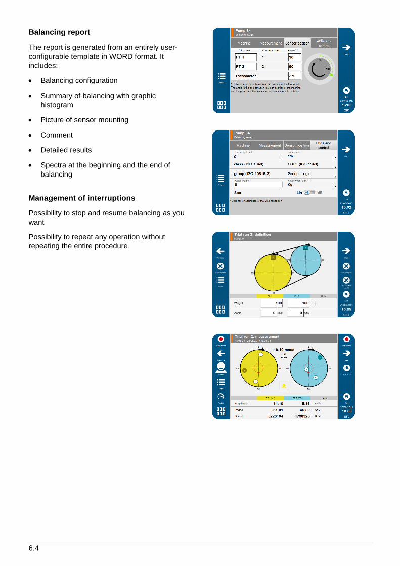
6.4
Balancing report
The report is generated from an entirely user-
configurable template in WORD format. It
includes:
• Balancing configuration
• Summary of balancing with graphic
histogram
• Picture of sensor mounting
• Comment
• Detailed results
• Spectra at the beginning and the end of
balancing
Management of interruptions
Possibility to stop and resume balancing as you
want
Possibility to repeat any operation without
repeating the entire procedure

6.5
WIRELESS 3-AXIS ACCELEROMETER
SPECIFICATIONS
Physical
• Dimensions: Ø40 x H115 mm
• Weight: 373 g
• Resistance to shocks: 5 000 g
• Mounting: M6 threaded hole
• Mounting accessories:
o Fixing studs o Magnet for planar surfaces, to be used
with flat bases o Indexed magnet for automatic
positioning of axes on planar surfaces, to be used with indexed bases
o Bipolar magnet for all surfaces
Battery
• Type: Li-ion
• Operating life: 8 hours
• Rechargeable through USB
• Automatic stand-by mode: after 10 min
Metrology
• Synchronous 3-axis acquisition (X, Y, Z)
• Bandwidth: 20 kHz on all axes
• Frequency range at 3 dB:
o 15 kHz (Z) o 6 kHz (XY)
• Full scale: 80 g
• Signal-to-Noise ratio: 80 dB
• Accuracy: +/- 3%
Environment
• Operating temperature: from -20°C to +80°C
• Protection: IP65
• ATEX Zone II certification
• IECEX certification (pending)
Communication
• Automatic sensor detection by
FIXTURLASER SMC
• FIXTURLASER SMC detection time upon
power up of sensor (ON/OFF): 30s
• Pairing: association of sensor to one
FIXTURLASER SMC at a time
• Coexistence:
o Several wireless sensors scan operate together in the same area.
o FIXTURLASER SMC operates with one triaxial wireless sensor at a time.
• Wireless protocol: Wi-Fi
• Range from 10 m to 20 m depending on the
environment
6.6
AUTOMATIC DIAGNOSIS
SPECIFICATIONS
Machine and component types
• Electric motors (synchronous, asynchronous,
DC)
• Pump
• Fan
• Compressors (Centrifuge, Lobed)
• Gearbox with up to 4 stages
• Bevel gearbox
• Roller
• Shaft
Main analysed defects
• Unbalance
• Misalignment
• Bearing and lubrication
• Mounting, clearance, friction
• Gear defects
• Cavitation
Symptom based approach
FIXTURLASER SMC automatically reproduces
the behavior of an expert user in front of
vibration data: a symptom-based analysis is
performed, thus avoiding limitations of simple
thresholds evaluation. Proven in many industrial
cases gathered over the years through the
ONEPROD measurement and analysis
SERVICES activity, FIXTURLASER SMC
provides results showing unrivalled relevance
and reliability.
Limitations
• Speed: 120 to 12000 RPM
• Roller Bearings
Results
From the analysis of the symptoms observed on
your rotating machines, FIXTURLASER SMC
provides, in a fully automatic mode:
• Advice and recommendation on the global
condition of the machine, taking into account
all measurement points
• Automatic detection of multiple defects on
the same machine
• Automatic detection of multiple defects on
the same measurement point
• Supply of a result, even with an incomplete
measurement, as soon as the first point is
measured
• For each defect:
o Localisation of the defect on the machine
o Severity of the defect o Confidence level o 1st level of recommendation for
maintenance action


Publication No. P-0320-GB
© 2017 ACOEM AB, Mölndal, Sweden
All rights reserved. No part of this manual may be copied or reproduced in any form or by any means without prior permission from ACOEM AB.