Embed Size (px)
Citation preview
STATIC TRANSFER SWITCH
STS207 LV & HV STS203 LV & HV
USER MANUAL
Eltek_UM_STS207&STS203_E_R1.0.docx
Static Transfer Switch
STS207 & STS203 User Manual Page 2 (32)
©2011. ELTEK DEUTSCHLAND GmbH. Eltek_UM_STS207&STS203_E_R1.0.docx
Notes to this manual ATTENTION! Read this manual carefully before installing and commissioning the specified module. This manual is a part of the delivered module. Familiarity with the contents of this manual is required for installing and operating the specified module. The function description in this manual corresponds to the stage of technology at the date of publish-ing. Technical changes and changes in form and content can be made at any time by the manufacturer without notice. There are no obligations to update the manual continually. The rules for prevention of accidents for the specific country and the general safety rules in accordance with IEC 364 must be observed. The module is manufactured in accordance with applicable DIN and VDE standards such as VDE 0106 (part 100) and VDE 0100 (part 410). The CE marking on the module confirms compliance with EU stand-ards 2006-95-EG (low voltage) and 2004-108-EG (electromagnetic compatibility) if the installation and operation instructions are followed. Supplier:
ELTEK DEUTSCHLAND GmbH BU Industrial Schillerstraße 16 D-32052 Herford
+ 49 (0) 5221 1708-210 FAX + 49 (0) 5221 1708-222 Email [email protected] Internet http://www.eltek.com
Please note: No part of this document may be reproduced or transmitted in any form or by any means -electronic or mechanical, including photocopying and recording- for whatever reason without the explic-it written permission of Eltek Deutschland GmbH. Changes and errors excepted. 2011. ELTEK DEUTSCHLAND GmbH. All rights reserved.
Static Transfer Switch
STS207 & STS203 User Manual Page 3 (32)
©2011. ELTEK DEUTSCHLAND GmbH. Eltek_UM_STS207&STS203_E_R1.0.docx
Revision history Revision: 1.0 Date: 2011-10-06
Revision Description of change Writer Date
1.0 First edition, based on “UM_STS207_WEB_E_R2.0”, STS203 (115 VAC/60 Hz version) included. RTH 2011-10-06
Static Transfer Switch
STS207 & STS203 User Manual Page 4 (32)
©2011. ELTEK DEUTSCHLAND GmbH. Eltek_UM_STS207&STS203_E_R1.0.docx
Contents
1. Safety instructions & notes to electronic waste disposal ................................................ 6
2. General Information .................................................................................................................... 7 2.1 Example of use ..................................................................................................................................................... 7 2.2 Operating modes .................................................................................................................................................. 8
2.2.1 "Inverter priority" (default setting) ........................................................................................................... 8 2.2.2 "Mains priority" .............................................................................................................................................. 8
3. Type Range/ Main Data ............................................................................................................. 8 3.1 Optional equipment for STS assembly: ........................................................................................................... 9 3.2 Front view: operating elements, indicators .................................................................................................. 10 3.3 Electrical connections ....................................................................................................................................... 11
3.3.1 Pin assignment of the rear side connector: .......................................................................................... 11 3.3.2 Pin assignment of the front side CAN-Bus connector (RJ11): .......................................................... 12 3.3.3 Pin assignment of the front side Ethernet connector (RJ45): .......................................................... 12
3.4 Cooling/Air flow direction................................................................................................................................. 13 3.5 Communication interfaces ............................................................................................................................... 13
3.5.1 CAN-Bus ....................................................................................................................................................... 13 3.5.2 Ethernet (Net Connection) ....................................................................................................................... 14
4. Handling ...................................................................................................................................... 15 4.1 Storage ................................................................................................................................................................. 15 4.2 Before commissioning ....................................................................................................................................... 15 4.3 Commissioning .................................................................................................................................................... 15 4.4 Operation ............................................................................................................................................................. 16
4.4.1 LED Indications ............................................................................................................................................ 16 4.4.2 Adjustment keys ........................................................................................................................................ 16 4.4.3 LC-Display: Indication of measured values and alarm messages .................................................... 17
5. Parameter adjustment/menu structure ............................................................................. 18 5.1 Adjustable parameters (customer menu) ..................................................................................................... 18 5.2 Structure of the customer menu .................................................................................................................... 19
6. Maintenance .............................................................................................................................. 21
7. Trouble shooting ....................................................................................................................... 21
8. Technical specifications .......................................................................................................... 23 8.1 Specific data (depending on the type) .......................................................................................................... 23 8.2 General technical data ...................................................................................................................................... 23 8.3 Dimensional drawings ....................................................................................................................................... 24
9 Appendix ...................................................................................................................................... 25 9.1 Service menu 1 ................................................................................................................................................... 25
9.1.1 Adjustable parameters in service menu 1 ............................................................................................ 25 9.1.2 Selection of “service menu 1” ................................................................................................................. 26
9.2. Service menu 2 .................................................................................................................................................. 27 9.2.1 Adjustable parameters in service menu 2 ............................................................................................ 27 9.2.2 Selection of “service menu 2” .................................................................................................................. 28
10. Your notes ................................................................................................................................ 29
Static Transfer Switch
STS207 & STS203 User Manual Page 5 (32)
©2011. ELTEK DEUTSCHLAND GmbH. Eltek_UM_STS207&STS203_E_R1.0.docx
Index of Figures
Figure 1. Block diagram “Example of use” ................................................................................................................. 7
Figure 2. AC Rack ACR INV222-6.75 ........................................................................................................................... 9
Figure 3. Front view...................................................................................................................................................... 10
Figure 4. Rear side connector .................................................................................................................................... 11
Figure 5. CAN-Bus connector ..................................................................................................................................... 12
Figure 6. Ethernet connector ..................................................................................................................................... 12
Figure 7. Module air flow ............................................................................................................................................. 13
Figure 8. Sample screenshot “Net Connection” ..................................................................................................... 14
Figure 9. LC-Display: Indication of measured values ............................................................................................. 17
Figure 10. Structure of the customer menu ........................................................................................................... 19
Figure 11. Continuation of the customer menu ..................................................................................................... 20
Figure 12. Display “Alarm Messages” ....................................................................................................................... 21
Figure 13. Module dimensions ................................................................................................................................... 24
Figure 14. Flow-chart of Service Menu 1 ............................................................................................................... 26
Figure 15. Flow-chart of Service Menu 2 ................................................................................................................ 28
Static Transfer Switch
STS207 & STS203 User Manual Page 6 (32)
©2011. ELTEK DEUTSCHLAND GmbH. Eltek_UM_STS207&STS203_E_R1.0.docx
1. Safety instructions & notes to electronic waste disposal
Warning!
Because several components of operating electrical modules are charged by dangerous voltage, the improper handling of electrical modules may cause accidents involving electrocution, injury, or material damages.
• Operation and maintenance of electrical devices must be performed by qualified skilled person-nel such as electricians in accordance with EN 50110-1 or IEC 60950.
• Install the device only in areas with limited access to unskilled personnel.
• Before starting work, the device must be disconnected from mains. Make sure that the device is earthed.
• Do not touch connector pins as they can be charged with dangerous voltage up to 30 seconds after disconnection.
• Only spare parts approved by the manufacturer must be used.
The correct disposal of electronic waste is the responsibility to recycle discarded electronic equipment and is necessary to achieve the chosen level to protect human health and the environment. In the case of waste disposal of your discarded equipment we recommend to contact a professional waste management company.
Static Transfer Switch
STS207 & STS203 User Manual Page 7 (32)
©2011. ELTEK DEUTSCHLAND GmbH. Eltek_UM_STS207&STS203_E_R1.0.docx
2. General Information
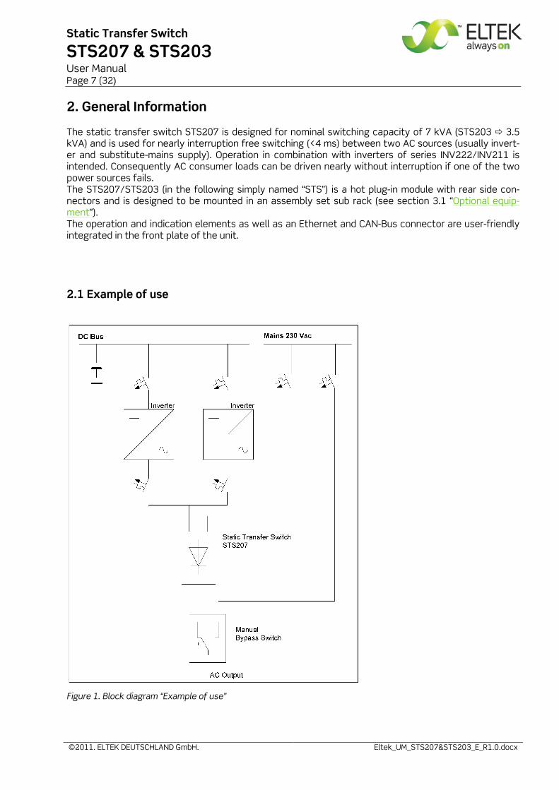
The static transfer switch STS207 is designed for nominal switching capacity of 7 kVA (STS203 3.5 kVA) and is used for nearly interruption free switching (<4 ms) between two AC sources (usually invert-er and substitute-mains supply). Operation in combination with inverters of series INV222/INV211 is intended. Consequently AC consumer loads can be driven nearly without interruption if one of the two power sources fails. The STS207/STS203 (in the following simply named “STS”) is a hot plug-in module with rear side con-nectors and is designed to be mounted in an assembly set sub rack (see section 3.1 “Optional equip-ment”). The operation and indication elements as well as an Ethernet and CAN-Bus connector are user-friendly integrated in the front plate of the unit.
2.1 Example of use
Figure 1. Block diagram “Example of use”
Static Transfer Switch
STS207 & STS203 User Manual Page 8 (32)
©2011. ELTEK DEUTSCHLAND GmbH. Eltek_UM_STS207&STS203_E_R1.0.docx
2.2 Operating modes
The static transfer switch STS is designed for the operating modes “inverter priority” and “mains priority” alternatively. The consumer load is fed by priority source as long as that source works faultlessly. REMARK: The unit's default setting is "Inverter priority". The priority source is programmable using "service menu 2".
2.2.1 "Inverter priority" (default setting)
At operating mode “inverter priority” the load is fed by inverters. But if the inverter(s) fail or overload occurs, the STS switches to “Load on Mains”.
2.2.2 "Mains priority"
At the operating mode “mains priority” the load is fed by AC mains. The STS switches to “Load on Invert-er” if mains fails provided that the load matches the output power of the inverters.
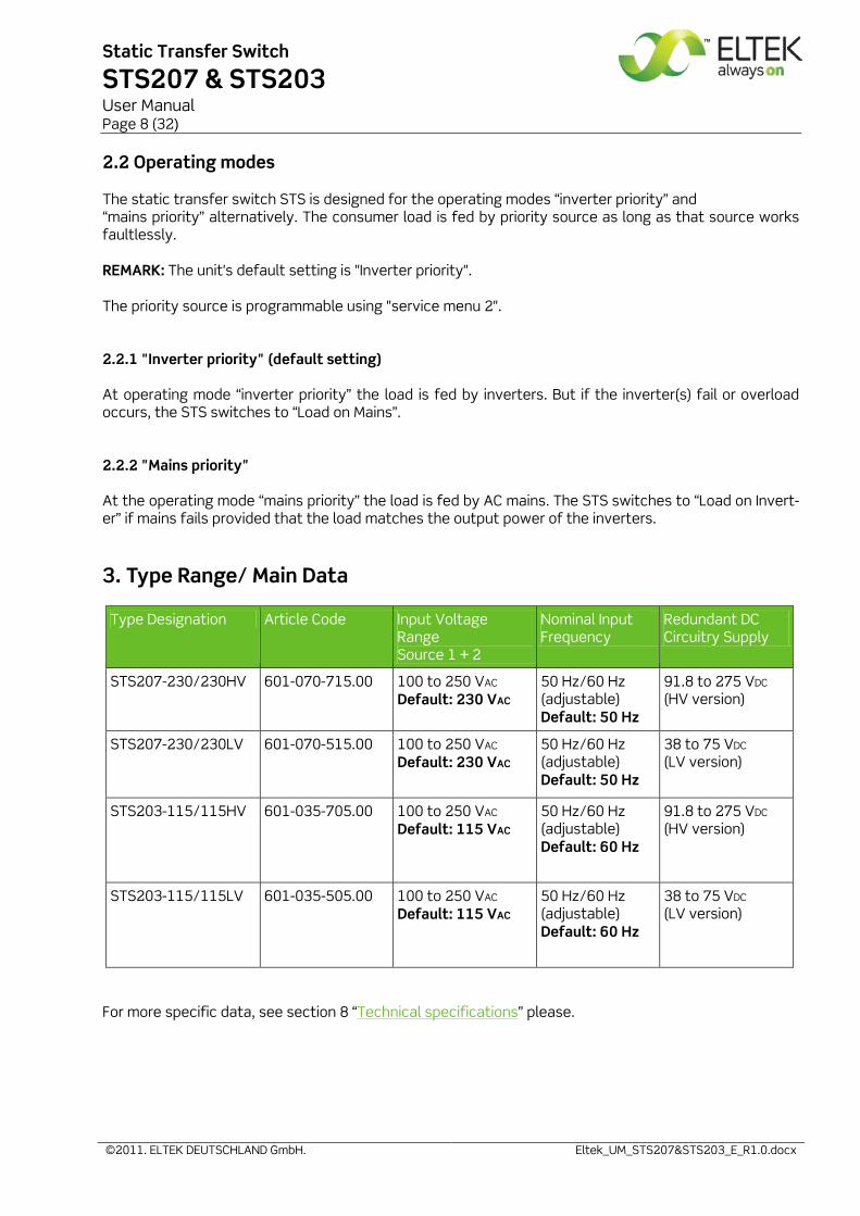
3. Type Range/ Main Data
Type Designation Article Code Input Voltage Range Source 1 + 2
Nominal Input Frequency
Redundant DC Circuitry Supply
STS207-230/230HV 601-070-715.00 100 to 250 VAC
Default: 230 VAC 50 Hz/60 Hz (adjustable) Default: 50 Hz
91.8 to 275 VDC (HV version)
STS207-230/230LV 601-070-515.00 100 to 250 VAC
Default: 230 VAC 50 Hz/60 Hz (adjustable) Default: 50 Hz
38 to 75 VDC (LV version)
STS203-115/115HV 601-035-705.00 100 to 250 VAC
Default: 115 VAC 50 Hz/60 Hz (adjustable) Default: 60 Hz
91.8 to 275 VDC (HV version)
STS203-115/115LV 601-035-505.00 100 to 250 VAC
Default: 115 VAC 50 Hz/60 Hz (adjustable) Default: 60 Hz
38 to 75 VDC (LV version)
For more specific data, see section 8 “Technical specifications” please.
Static Transfer Switch
STS207 & STS203 User Manual Page 9 (32)
©2011. ELTEK DEUTSCHLAND GmbH. Eltek_UM_STS207&STS203_E_R1.0.docx
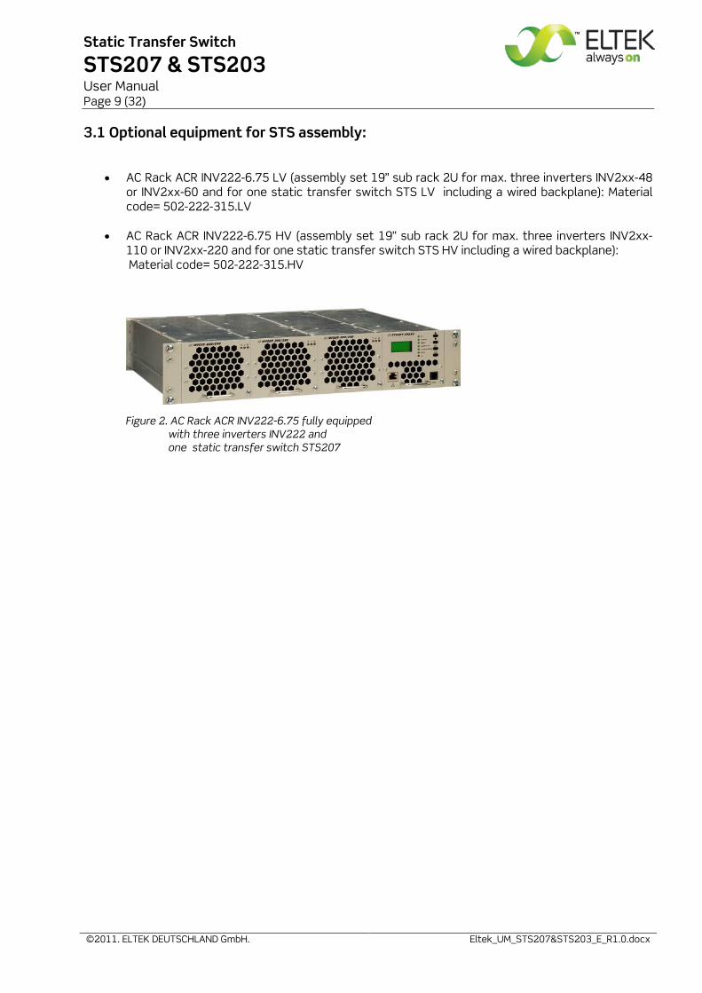
3.1 Optional equipment for STS assembly:
• AC Rack ACR INV222-6.75 LV (assembly set 19” sub rack 2U for max. three inverters INV2xx-48
or INV2xx-60 and for one static transfer switch STS LV including a wired backplane): Material code= 502-222-315.LV
• AC Rack ACR INV222-6.75 HV (assembly set 19” sub rack 2U for max. three inverters INV2xx-
110 or INV2xx-220 and for one static transfer switch STS HV including a wired backplane): Material code= 502-222-315.HV
Figure 2. AC Rack ACR INV222-6.75 fully equipped with three inverters INV222 and one static transfer switch STS207
Static Transfer Switch
STS207 & STS203 User Manual Page 10 (32)
©2011. ELTEK DEUTSCHLAND GmbH. Eltek_UM_STS207&STS203_E_R1.0.docx
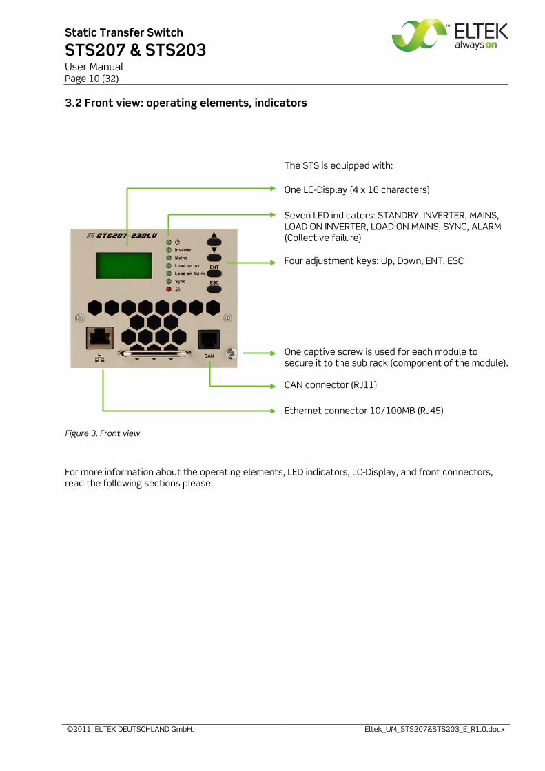
3.2 Front view: operating elements, indicators
Figure 3. Front view
For more information about the operating elements, LED indicators, LC-Display, and front connectors, read the following sections please.
The STS is equipped with: One LC-Display (4 x 16 characters)
Seven LED indicators: STANDBY, INVERTER, MAINS, LOAD ON INVERTER, LOAD ON MAINS, SYNC, ALARM (Collective failure) Four adjustment keys: Up, Down, ENT, ESC
One captive screw is used for each module to secure it to the sub rack (component of the module).
CAN connector (RJ11)
Ethernet connector 10/100MB (RJ45)
Static Transfer Switch
STS207 & STS203 User Manual Page 11 (32)
©2011. ELTEK DEUTSCHLAND GmbH. Eltek_UM_STS207&STS203_E_R1.0.docx
3.3 Electrical connections
The STS is equipped with:
• 1 rear side connector for: AC input 1 (inverter), AC input 2 (mains), AC output and signalling • 1 front side connector RJ11 (additional CAN-Bus connector) • 1 front side connector RJ45 (Ethernet 10/100MB)
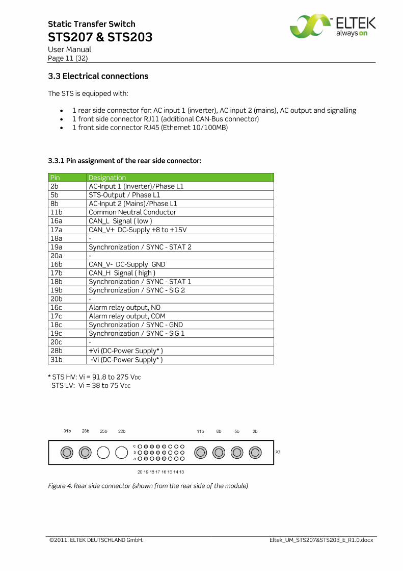
3.3.1 Pin assignment of the rear side connector:
Pin Designation 2b AC-Input 1 (Inverter)/Phase L1 5b STS-Output / Phase L1 8b AC-Input 2 (Mains)/Phase L1 11b Common Neutral Conductor 16a CAN_L Signal ( low ) 17a CAN_V+ DC-Supply +8 to +15V 18a - 19a Synchronization / SYNC - STAT 2 20a - 16b CAN_V- DC-Supply GND 17b CAN_H Signal ( high ) 18b Synchronization / SYNC - STAT 1 19b Synchronization / SYNC - SIG 2 20b - 16c Alarm relay output, NO 17c Alarm relay output, COM 18c Synchronization / SYNC - GND 19c Synchronization / SYNC - SIG 1 20c - 28b +Vi (DC-Power Supply* ) 31b -Vi (DC-Power Supply* )
* STS HV: Vi = 91.8 to 275 VDC
STS LV: Vi = 38 to 75 VDC
Figure 4. Rear side connector (shown from the rear side of the module)
Static Transfer Switch
STS207 & STS203 User Manual Page 12 (32)
©2011. ELTEK DEUTSCHLAND GmbH. Eltek_UM_STS207&STS203_E_R1.0.docx
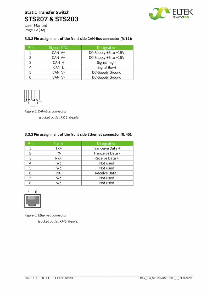
3.3.2 Pin assignment of the front side CAN-Bus connector (RJ11):
Pin Signals CAN Designation 1 CAN_V+ DC-Supply +8 to +15V 2 CAN_V+ DC-Supply +8 to +15V 3 CAN_H Signal (high) 4 CAN_L Signal (low) 5 CAN_V- DC-Supply Ground 6 CAN_V- DC-Supply Ground
Figure 5. CAN-Bus connector
(socket outlet RJ11, 6-pole)
3.3.3 Pin assignment of the front side Ethernet connector (RJ45):
Pin Name Designation 1 TX+ Tranceive Data + 2 TX- Tranceive Data - 3 RX+ Receive Data + 4 n/c Not used 5 n/c Not used 6 RX- Receive Data - 7 n/c Not used 8 n/c Not used
Figure 6. Ethernet connector
(socket outlet RJ45, 8-pole)
Static Transfer Switch
STS207 & STS203 User Manual Page 13 (32)
©2011. ELTEK DEUTSCHLAND GmbH. Eltek_UM_STS207&STS203_E_R1.0.docx
3.4 Cooling/Air flow direction
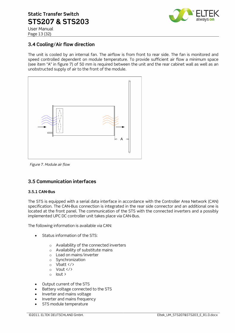
The unit is cooled by an internal fan. The airflow is from front to rear side. The fan is monitored and speed controlled dependent on module temperature. To provide sufficient air flow a minimum space (see item “A” in figure 7) of 50 mm is required between the unit and the rear cabinet wall as well as an unobstructed supply of air to the front of the module.
Figure 7. Module air flow
3.5 Communication interfaces
3.5.1 CAN-Bus
The STS is equipped with a serial data interface in accordance with the Controller Area Network (CAN) specification. The CAN-Bus connection is integrated in the rear side connector and an additional one is located at the front panel. The communication of the STS with the connected inverters and a possibly implemented UPC DC controller unit takes place via CAN-Bus. The following information is available via CAN:
• Status information of the STS:
o Availability of the connected inverters o Availability of substitute mains o Load on mains/inverter o Synchronization o Vbatt </> o Vout </> o Iout >
• Output current of the STS • Battery voltage connected to the STS • Inverter and mains voltage • Inverter and mains frequency • STS module temperature
Static Transfer Switch
STS207 & STS203 User Manual Page 14 (32)
©2011. ELTEK DEUTSCHLAND GmbH. Eltek_UM_STS207&STS203_E_R1.0.docx
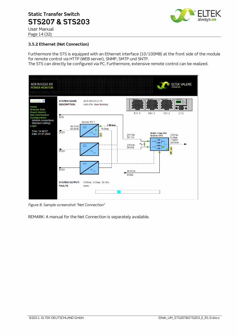
3.5.2 Ethernet (Net Connection)
Furthermore the STS is equipped with an Ethernet interface (10/100MB) at the front side of the module for remote control via HTTP (WEB server), SNMP, SMTP und SNTP. The STS can directly be configured via PC. Furthermore, extensive remote control can be realized.
Figure 8. Sample screenshot “Net Connection”
REMARK: A manual for the Net Connection is separately available.
Static Transfer Switch
STS207 & STS203 User Manual Page 15 (32)
©2011. ELTEK DEUTSCHLAND GmbH. Eltek_UM_STS207&STS203_E_R1.0.docx
4. Handling
4.1 Storage
The STS must be stored in a dry, dust free environment with a storage temperature according to specific data (see section 8).
4.2 Before commissioning
REMARK: The LV device is delivered with factory set defaults according to a 48 V battery system (24 cells, lead acid battery) the HV device is delivered with factory set defaults according to a 108 V battery system (54 cells, lead acid battery). The default value of the AC voltage is factory set to 230 V/50 Hz (STS207) or 115 V/60 Hz (STS203) dependent on the type (see section 3 “Type range” and section 8 “Technical specifications” as well). If other battery systems with different cell numbers should be used or the STS should be connected to another AC voltage, the STS must be reconfigured be-fore.
The factory preset defaults and threshold values and their adjustment ranges/steps as well are listed in the Service Menus (see section 9 „Appendix“ please). If necessary, reconfiguration of the STS can be carried out using adjustment keys or via WEB connection at PC alternatively. Operation using adjustment keys and menu navigation as well is described at the following sections. For operation via WEB connection please see the specific user manual „WEB connection“.
4.3 Commissioning
REMARK: Before commissioning the module, make sure that the battery voltage for re-dundant circuitry supply of the STS and voltage values of both AC input sources corresponds to the specification as specified on the type plate. Make sure that the STS is correctly configured according to the used battery system and con-nected AC voltages (value/frequency) as well (see section 4.2 above “Before commissioning” please).
1. Carefully unpack the unit 2. Put the unit into the provided slot to the right of the sub rack. 3. Carefully slide in the unit until the module connector touched the backplane connector. 4. Increase the force until the unit fits in completely. Avoid using too much force. If the unit does not
fit in, begin again at step 2. 5. Secure the module using the captive screw provided with the module.
Switch-ON/Switch-OFF: The STS is switched ON/OFF by external input fuses
CAUTION: After the module is switched OFF the internal capacitors are still fully charged. Do not touch connector pins as they can still be charged with dangerous voltage after disconnection.
Static Transfer Switch
STS207 & STS203 User Manual Page 16 (32)
©2011. ELTEK DEUTSCHLAND GmbH. Eltek_UM_STS207&STS203_E_R1.0.docx
4.4 Operation
The operation of the unit takes place with keys located on the front side of the unit. All main functional parameters and measured values are displayed on the front side LCD panel (text indicator) as well as with LED indicators. The different functions are described in the following sections.
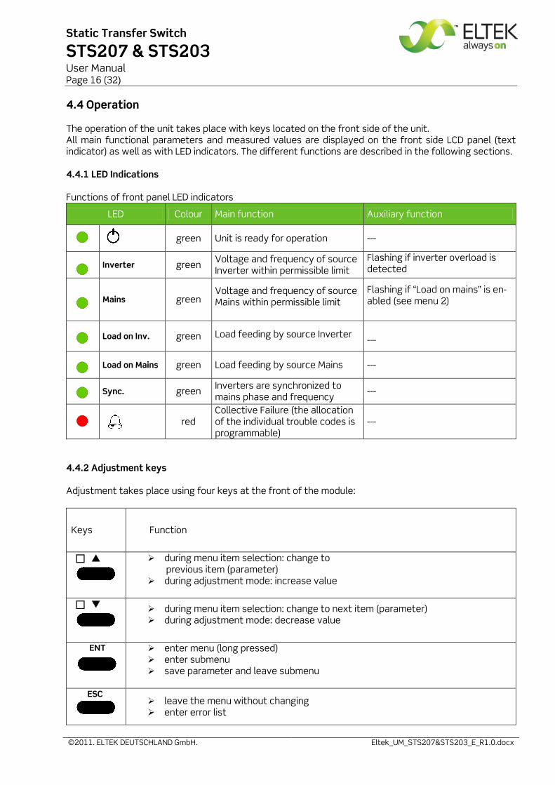
4.4.1 LED Indications
Functions of front panel LED indicators
LED Colour Main function Auxiliary function
green Unit is ready for operation ---
Inverter green Voltage and frequency of source
Inverter within permissible limit Flashing if inverter overload is detected
Mains green Voltage and frequency of source Mains within permissible limit
Flashing if “Load on mains” is en-abled (see menu 2)
Load on Inv. green Load feeding by source Inverter
---
Load on Mains green Load feeding by source Mains ---
Sync. green Inverters are synchronized to
mains phase and frequency ---
red
Collective Failure (the allocation of the individual trouble codes is programmable)
---
4.4.2 Adjustment keys
Adjustment takes place using four keys at the front of the module:
Keys Function
during menu item selection: change to previous item (parameter)
during adjustment mode: increase value
during menu item selection: change to next item (parameter) during adjustment mode: decrease value
ENT
enter menu (long pressed) enter submenu save parameter and leave submenu
ESC leave the menu without changing
enter error list
Static Transfer Switch
STS207 & STS203 User Manual Page 17 (32)
©2011. ELTEK DEUTSCHLAND GmbH. Eltek_UM_STS207&STS203_E_R1.0.docx
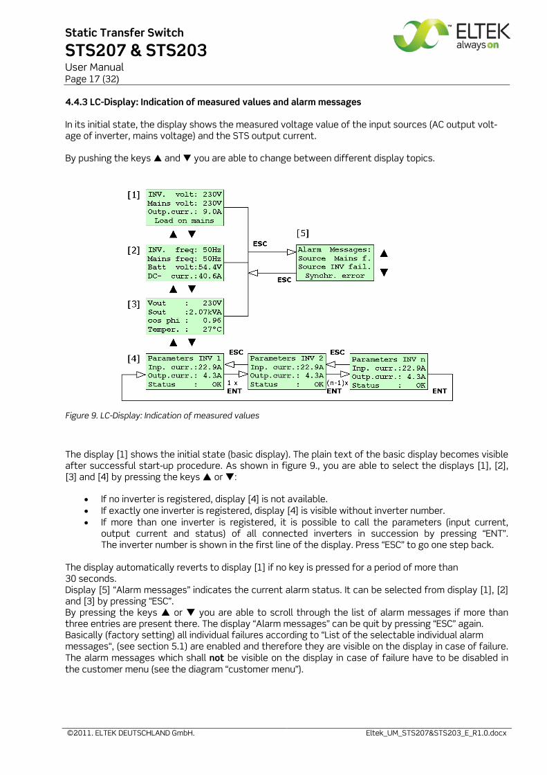
4.4.3 LC-Display: Indication of measured values and alarm messages
In its initial state, the display shows the measured voltage value of the input sources (AC output volt-age of inverter, mains voltage) and the STS output current.
By pushing the keys and you are able to change between different display topics.
Figure 9. LC-Display: Indication of measured values
The display [1] shows the initial state (basic display). The plain text of the basic display becomes visible after successful start-up procedure. As shown in figure 9., you are able to select the displays [1], [2], [3] and [4] by pressing the keys or :
• If no inverter is registered, display [4] is not available. • If exactly one inverter is registered, display [4] is visible without inverter number. • If more than one inverter is registered, it is possible to call the parameters (input current,
output current and status) of all connected inverters in succession by pressing “ENT”. The inverter number is shown in the first line of the display. Press “ESC” to go one step back.
The display automatically reverts to display [1] if no key is pressed for a period of more than 30 seconds. Display [5] “Alarm messages” indicates the current alarm status. It can be selected from display [1], [2] and [3] by pressing “ESC”. By pressing the keys or you are able to scroll through the list of alarm messages if more than three entries are present there. The display “Alarm messages” can be quit by pressing “ESC” again. Basically (factory setting) all individual failures according to “List of the selectable individual alarm messages“, (see section 5.1) are enabled and therefore they are visible on the display in case of failure. The alarm messages which shall not be visible on the display in case of failure have to be disabled in the customer menu (see the diagram “customer menu”).
Static Transfer Switch
STS207 & STS203 User Manual Page 18 (32)
©2011. ELTEK DEUTSCHLAND GmbH. Eltek_UM_STS207&STS203_E_R1.0.docx
5. Parameter adjustment/menu structure
The LV device is delivered with factory set defaults according to a 48 V battery system (24 cells, lead acid battery). The HV device is delivered with factory set defaults according to a 108 V battery system (54 cells, lead acid battery). The default value of the AC voltage is factory set to 230 V/50 Hz (STS207) or 115 V/60 Hz (STS203) dependent on the type (see section 3 “Type range” and section 8 “Technical specifications” as well). If other battery systems with different cell numbers should be used or the STS should be connected to another AC voltage, the STS must be reconfigured before. In this case reconfiguration takes place using service menu 1 and 2 (see section 9 „Appendix“) or the network menu (see the specific user manual “WEB connection”) as well.
ATTENTION: Configuration should be carried out only by qualified and skilled service personnel.
In the following sections the adjustable parameters in the customer menu (accessible to each customer) are described. Those are general adjustments such as indicated display language, time delay values, content of collective failure signal etc. IMPORTANT: In any case the number of connected inverters and number of redundant inverters as well must be configured.
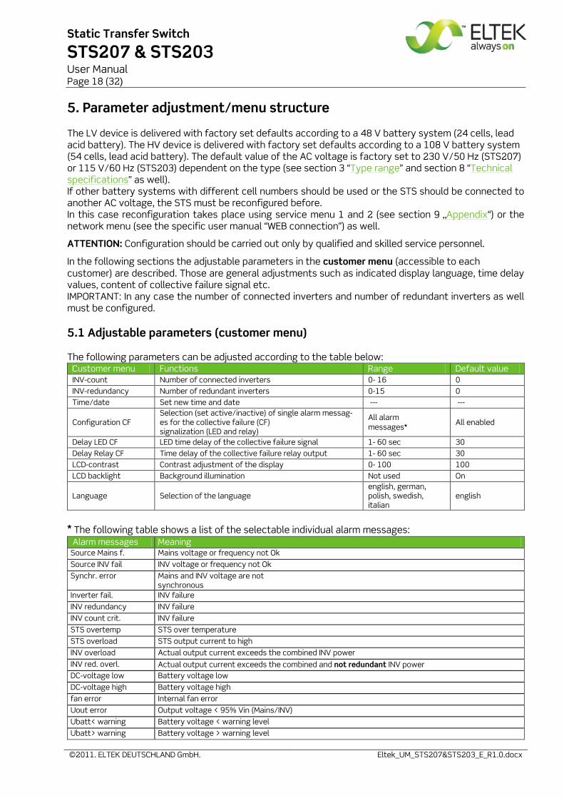
5.1 Adjustable parameters (customer menu)
The following parameters can be adjusted according to the table below: Customer menu Functions Range Default value INV-count Number of connected inverters 0- 16 0 INV-redundancy Number of redundant inverters 0-15 0 Time/date Set new time and date --- ---
Configuration CF Selection (set active/inactive) of single alarm messag-es for the collective failure (CF) signalization (LED and relay)
All alarm messages*
All enabled
Delay LED CF LED time delay of the collective failure signal 1- 60 sec 30 Delay Relay CF Time delay of the collective failure relay output 1- 60 sec 30 LCD-contrast Contrast adjustment of the display 0- 100 100 LCD backlight Background illumination Not used On
Language Selection of the language english, german, polish, swedish, italian
english
* The following table shows a list of the selectable individual alarm messages: Alarm messages Meaning Source Mains f. Mains voltage or frequency not Ok Source INV fail INV voltage or frequency not Ok Synchr. error Mains and INV voltage are not
synchronous Inverter fail. INV failure INV redundancy INV failure INV count crit. INV failure STS overtemp STS over temperature STS overload STS output current to high INV overload Actual output current exceeds the combined INV power INV red. overl. Actual output current exceeds the combined and not redundant INV power DC-voltage low Battery voltage low DC-voltage high Battery voltage high fan error Internal fan error Uout error Output voltage < 95% Vin (Mains/INV) Ubatt< warning Battery voltage < warning level Ubatt> warning Battery voltage > warning level
Static Transfer Switch
STS207 & STS203 User Manual Page 19 (32)
©2011. ELTEK DEUTSCHLAND GmbH. Eltek_UM_STS207&STS203_E_R1.0.docx
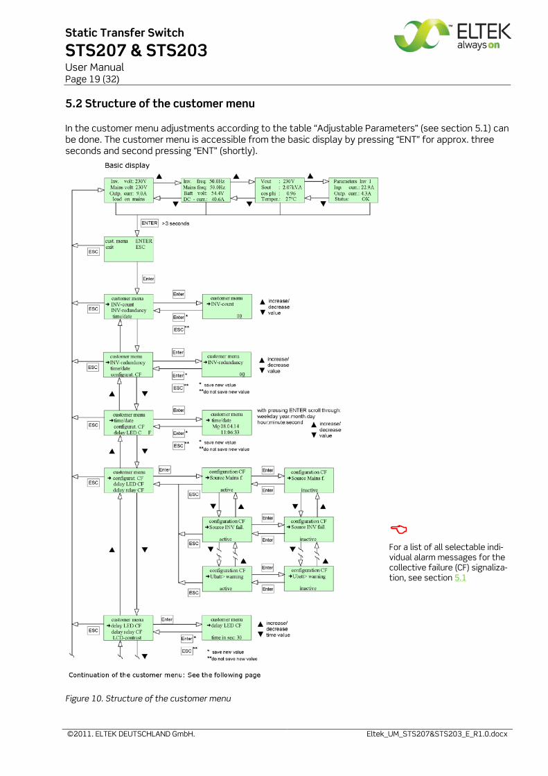
5.2 Structure of the customer menu
In the customer menu adjustments according to the table “Adjustable Parameters” (see section 5.1) can be done. The customer menu is accessible from the basic display by pressing “ENT” for approx. three seconds and second pressing “ENT” (shortly).
For a list of all selectable indi-vidual alarm messages for the collective failure (CF) signaliza-tion, see section 5.1
Figure 10. Structure of the customer menu
Static Transfer Switch
STS207 & STS203 User Manual Page 20 (32)
©2011. ELTEK DEUTSCHLAND GmbH. Eltek_UM_STS207&STS203_E_R1.0.docx
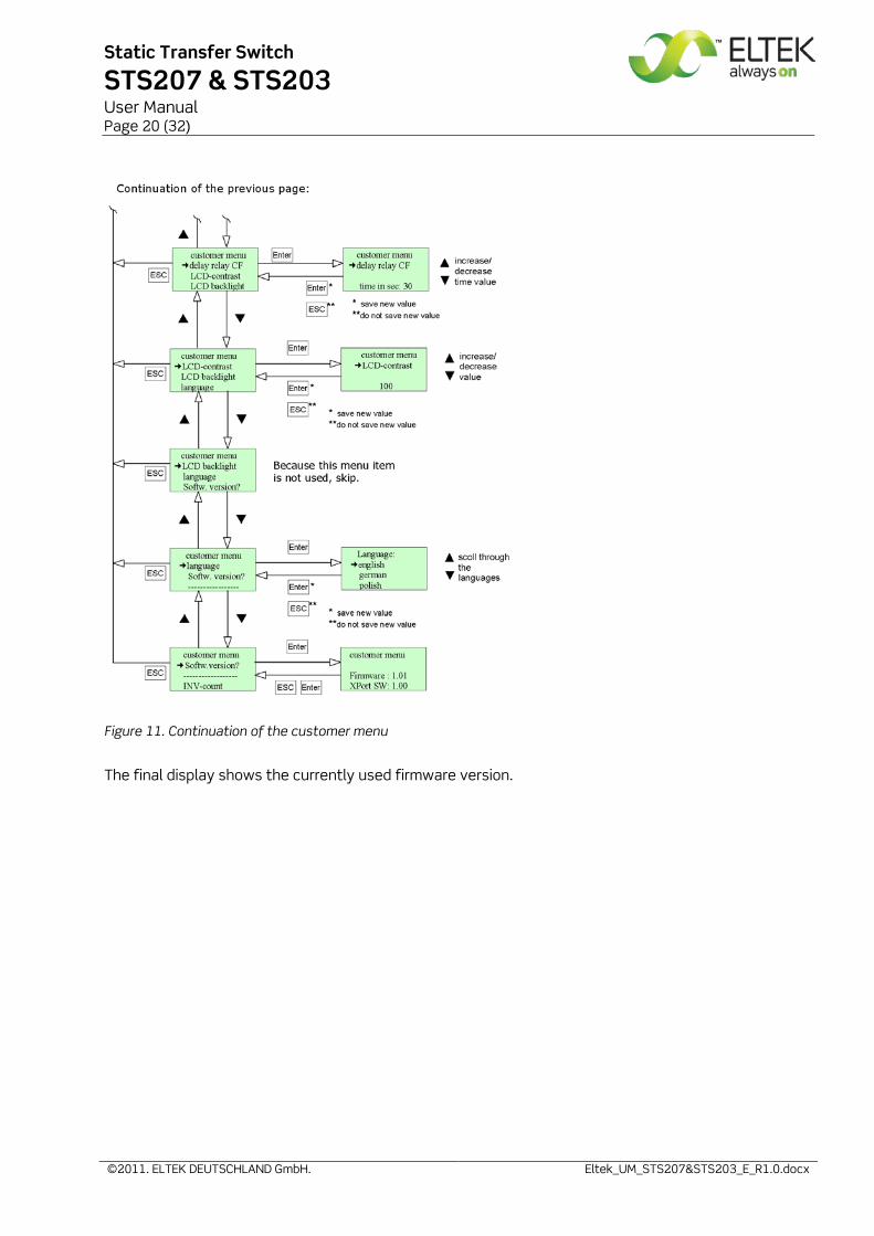
Figure 11. Continuation of the customer menu
The final display shows the currently used firmware version.
Static Transfer Switch
STS207 & STS203 User Manual Page 21 (32)
©2011. ELTEK DEUTSCHLAND GmbH. Eltek_UM_STS207&STS203_E_R1.0.docx
6. Maintenance
In general the module is maintenance-free. Exclusively the fan is a component consisting of moving parts. Although it may be expected that the operating life of the fan is more than five years it is rec-ommended to exchange the fan every five years. By way of precaution a yearly inspection with following checks is recommended:
• Mechanical/visual inspection • Removal of dust and dirt, especially on radiator surfaces • Check for internal dust or humidity
Attention! Dust combined with moisture or water may influence or destroy the internal electronic circuits. Dust inside the unit can be blown out with dry compressed air. Avoid using too high air pressure. The interval between the checks depends on ambient conditions of the installed module.
7. Trouble shooting
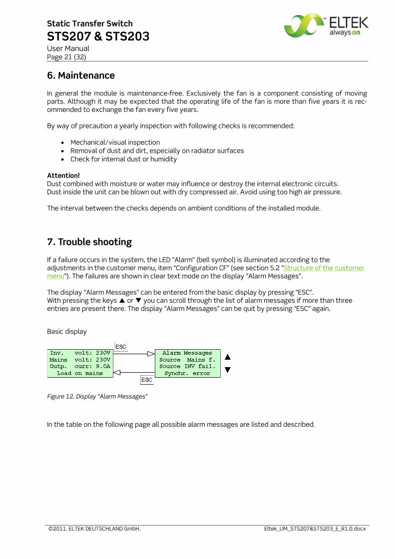
If a failure occurs in the system, the LED “Alarm” (bell symbol) is illuminated according to the adjustments in the customer menu, item “Configuration CF” (see section 5.2 “Structure of the customer menu”). The failures are shown in clear text mode on the display “Alarm Messages”. The display “Alarm Messages” can be entered from the basic display by pressing “ESC”. With pressing the keys or you can scroll through the list of alarm messages if more than three entries are present there. The display “Alarm Messages” can be quit by pressing “ESC” again.
Basic display
Figure 12. Display “Alarm Messages”
In the table on the following page all possible alarm messages are listed and described.
Static Transfer Switch
STS207 & STS203 User Manual Page 22 (32)
©2011. ELTEK DEUTSCHLAND GmbH. Eltek_UM_STS207&STS203_E_R1.0.docx
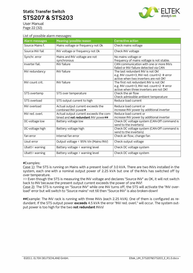
List of possible alarm messages: Alarm messages Meaning/possible reason Corrective action
Source Mains f. Mains voltage or frequency not Ok Check mains voltage
Source INV fail INV voltage or frequency not Ok Check INV voltage
Synchr. error Mains and INV voltage are not synchronous
No mains voltage or frequency of mains voltage is not stable.
Inverter fail. INV failure CAN communication with one or more INVs failed or INV failure detected via CAN
INV redundancy INV failure The last redundant INV is not Ok! e.g. INV count=3, INV red. count=2 error active when two inverters are not OK!
INV count crit. INV failure The first not redundant INV is not Ok! e.g. INV count=3, INV red. count=2 error active when three inverters are not OK!
STS overtemp STS over temperature Check the air flow Check admissible ambient temperature
STS overload STS output current to high Reduce load current
INV overload Actual output current exceeds the combined INV power#
Reduce load current or increase INV power by additional inverter
INV red. overl. Actual output current exceeds the com-bined and not redundant INV power##
Reduce load current or increase INV power by additional inverter
DC-voltage low Battery voltage low Check DC voltage system (CAN-Off command is send to the inverters)
DC-voltage high Battery voltage high Check DC voltage system (CAN-Off command is send to the inverters)
fan error Internal fan error Check air flow, change fan
Uout error Output voltage < 95% Vin (Mains/INV) Check output voltage
Ubatt< warning Battery voltage < warning level Check DC voltage system
Ubatt> warning Battery voltage > warning level Check DC voltage system
#Examples: Case 1): The STS is running on Mains with a present load of 3.0 kVA. There are two INVs installed in the system, each one with a nominal output power of 2.25 kVA but one of the INVs has switched off by over temperature. >> Even though the STS is measuring the INV voltage and declares "Source INV" as OK, it will not switch back to INV because the present output current exceeds the power of one INV! Case 2): The STS is running on "Source INV" while one INV turns off, the STS will activate the "INV over-load" error but will switch to "Source mains" not till then "Source INV" is also broken-down! ##Example: The INV rack is running with three INVs (each 2.25 kVA). One of them is configured as re-dundant. If the STS output power exceeds 4.5 kVA the error “INV red. overl.” will occur. The system out-put power is too high for the two not redundant INVs!
Static Transfer Switch
STS207 & STS203 User Manual Page 23 (32)
©2011. ELTEK DEUTSCHLAND GmbH. Eltek_UM_STS207&STS203_E_R1.0.docx
8. Technical specifications
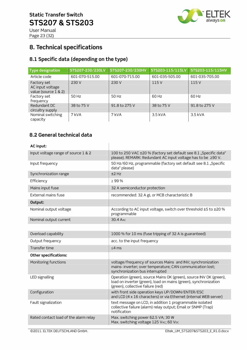
8.1 Specific data (depending on the type)
Type designation STS207-230/230LV STS207-230/230HV STS203-115/115LV STS203-115/115HV
Article code 601-070-515.00 601-070-715.00 601-035-505.00 601-035-705.00
Factory set AC input voltage value (source 1 & 2)
230 V 230 V 115 V 115 V
Factory set frequency
50 Hz 50 Hz 60 Hz 60 Hz
Redundant DC circuitry supply
38 to 75 V 91.8 to 275 V 38 to 75 V 91.8 to 275 V
Nominal switching capacity
7 kVA 7 kVA 3.5 kVA 3.5 kVA
8.2 General technical data
AC input:
Input voltage range of source 1 & 2 100 to 250 VAC ±20 % (factory set default see 8.1 „Specific data” please). REMARK: Redundant AC input voltage has to be ≥90 V.
Input frequency 50 Hz/60 Hz, programmable (factory set default see 8.1 „Specific data” please)
Synchronization range ±2 Hz
Efficiency ≥ 99 %
Mains input fuse 32 A semiconductor protection
External mains fuse recommended: 32 A gL or MCB characteristic B
Output:
Nominal output voltage According to AC input voltage, switch over threshold ±5 to ±20 % programmable
Nominal output current 30.4 AAC
Overload capability 1000 % for 10 ms (fuse tripping of 32 A is guaranteed)
Output frequency acc. to the input frequency
Transfer time ≤4 ms
Other specifications:
Monitoring functions voltage/frequency of sources Mains and INV; synchronization mains- inverter; over temperature; CAN communication lost; synchronization bus interrupted
LED signalling Operation (green), source Mains OK (green), source INV OK (green), load on inverter (green), load on mains (green), synchronization (green), collective failure (red)
Configuration with front side operation keys UP/DOWN/ENTER/ESC and LCD (4 x 16 characters) or via Ethernet (internal WEB server)
Fault signalization text message on LCD, in addition 1 programmable isolated collective failure (alarm) relay output; Email or SNMP (Trap) notification
Rated contact load of the alarm relay Max. switching power 62.5 VA; 30 W Max. switching voltage 125 VAC; 60 VDC
Static Transfer Switch
STS207 & STS203 User Manual Page 24 (32)
©2011. ELTEK DEUTSCHLAND GmbH. Eltek_UM_STS207&STS203_E_R1.0.docx
Communications interface CAN-Bus, proprietary protocol; redundant synchronization bus; Ethernet 10/100 MB Half/Full (WEB server, SNMP, SMTP, SNTP)
Ambient temperature operation: -20 °C to +55 °C; storage: -40 °C to + 85 °C
Cooling fan cooling (temperature regulated; monitored)
Max. installation altitude ≤1500 m
Audible noise ≤45 dBA
Type of construction 1/4 x19’’, 2 U
Surfaces powder coating RAL 7035 (front panel only) with black imprint; constructive parts: anodized metal
Dimensions (W/H/D) 106.4/88.4/335 mm plus 25.5 mm handle length
Minimum installation depth 400 mm plus 25.5 mm handle length (in combination with an as-sembly set 19’’ sub rack)
Weight approx. 2.2 kg
Connectors Rear: AC inputs/output, DC input and signalization (DIN 41612-M-connector); Front: Ethernet (RJ45), CAN (RJ11)
Applicable standards:
Mechanical construction acc. to VDE 0160 edition 5.88 chapter 7.2.2
Protection class IP20
Climatic conditions acc. to IEC 721-3-3 class 3K3/3Z1/3B1/3C2/3S2/3M2
RFI suppression / immunity CE- label; ((EN50081-1; EN55011/55022 class “B”; EN50082-2; EN61000-4 part 2/3/4/5)
Compliance to safety standards acc. to EN60950-1; VDO0100 T410; VDO0110; EN60146
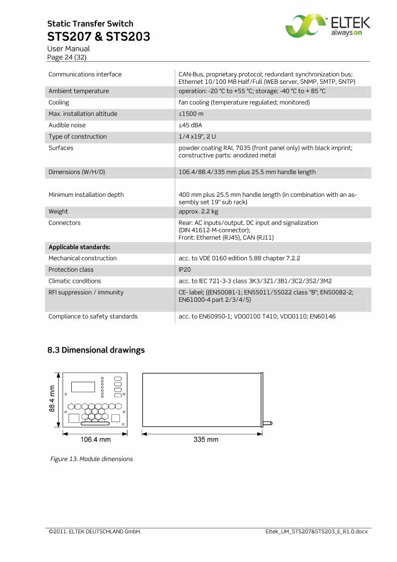
8.3 Dimensional drawings
Figure 13. Module dimensions
Static Transfer Switch
STS207 & STS203 User Manual Page 25 (32)
©2011. ELTEK DEUTSCHLAND GmbH. Eltek_UM_STS207&STS203_E_R1.0.docx
9 Appendix
9.1 Service menu 1
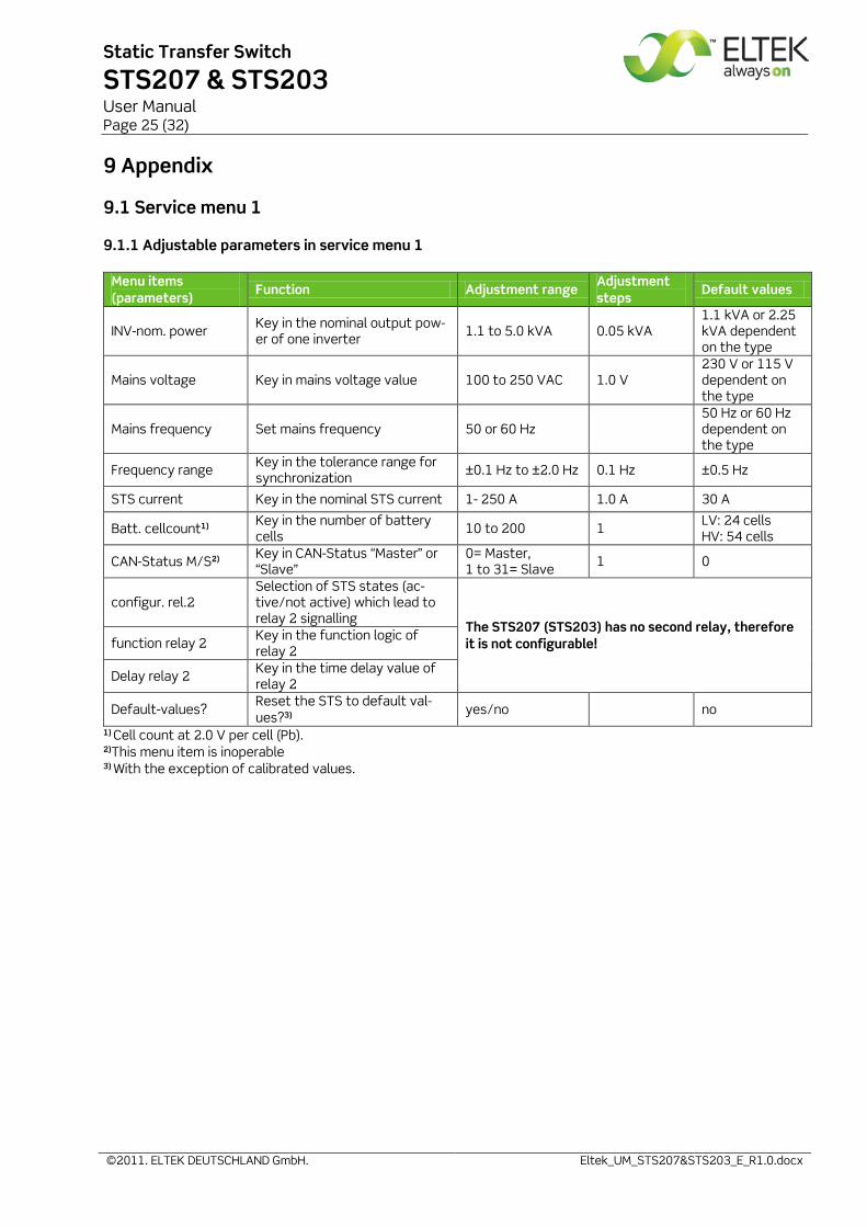
9.1.1 Adjustable parameters in service menu 1
Menu items (parameters)
Function Adjustment range Adjustment steps
Default values
INV-nom. power Key in the nominal output pow-er of one inverter 1.1 to 5.0 kVA 0.05 kVA
1.1 kVA or 2.25 kVA dependent on the type
Mains voltage Key in mains voltage value 100 to 250 VAC 1.0 V 230 V or 115 V dependent on the type
Mains frequency Set mains frequency 50 or 60 Hz 50 Hz or 60 Hz dependent on the type
Frequency range Key in the tolerance range for synchronization ±0.1 Hz to ±2.0 Hz 0.1 Hz ±0.5 Hz
STS current Key in the nominal STS current 1- 250 A 1.0 A 30 A
Batt. cellcount1) Key in the number of battery cells 10 to 200 1 LV: 24 cells
HV: 54 cells
CAN-Status M/S2) Key in CAN-Status “Master” or “Slave”
0= Master, 1 to 31= Slave 1 0
configur. rel.2 Selection of STS states (ac-tive/not active) which lead to relay 2 signalling
The STS207 (STS203) has no second relay, therefore it is not configurable! function relay 2 Key in the function logic of
relay 2
Delay relay 2 Key in the time delay value of relay 2
Default-values? Reset the STS to default val-ues?3)
yes/no
no
1) Cell count at 2.0 V per cell (Pb). 2)This menu item is inoperable 3) With the exception of calibrated values.
Static Transfer Switch
STS207 & STS203 User Manual Page 26 (32)
©2011. ELTEK DEUTSCHLAND GmbH. Eltek_UM_STS207&STS203_E_R1.0.docx
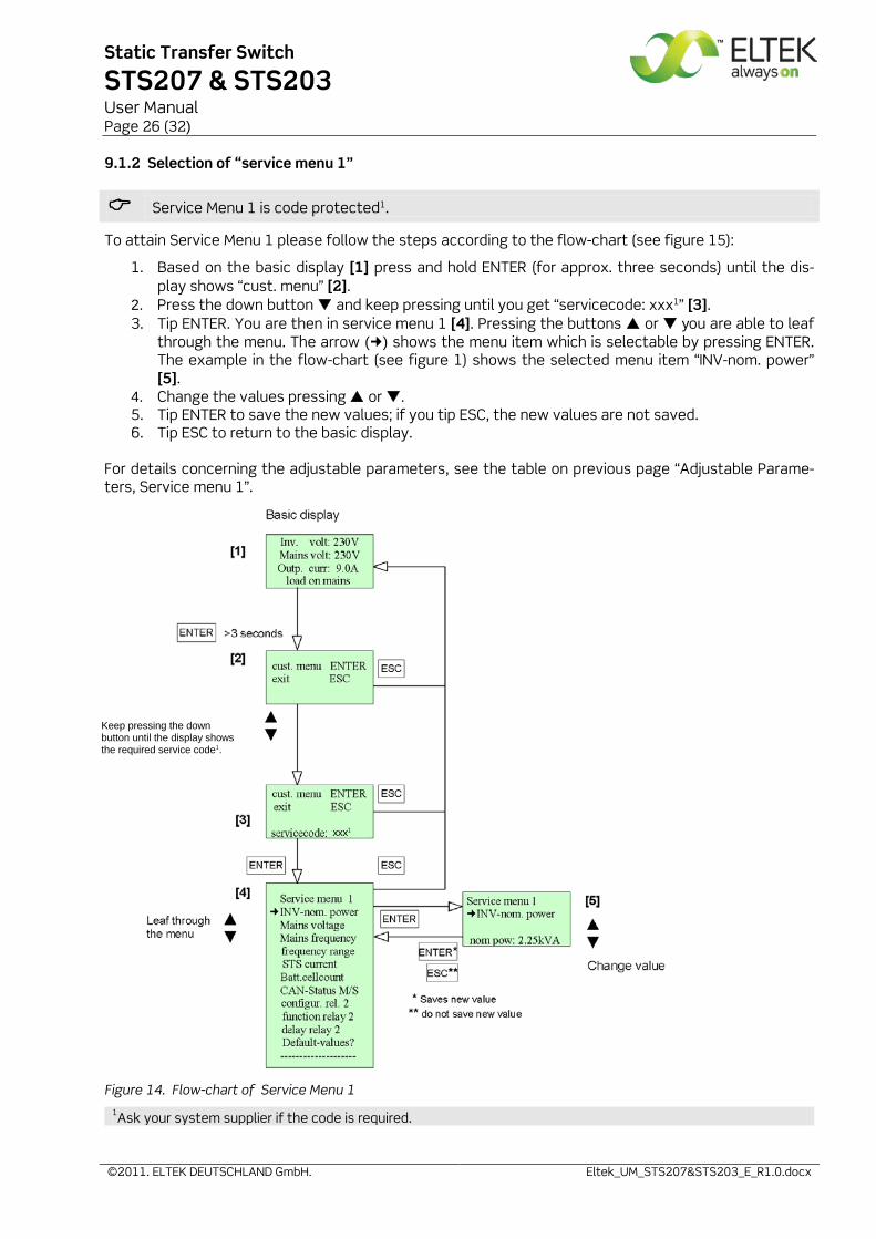
9.1.2 Selection of “service menu 1”
Service Menu 1 is code protected1.
To attain Service Menu 1 please follow the steps according to the flow-chart (see figure 15):
1. Based on the basic display [1] press and hold ENTER (for approx. three seconds) until the dis-play shows “cust. menu” [2].
2. Press the down button and keep pressing until you get “servicecode: xxx1” [3]. 3. Tip ENTER. You are then in service menu 1 [4]. Pressing the buttons or you are able to leaf
through the menu. The arrow () shows the menu item which is selectable by pressing ENTER. The example in the flow-chart (see figure 1) shows the selected menu item “INV-nom. power” [5].
4. Change the values pressing or . 5. Tip ENTER to save the new values; if you tip ESC, the new values are not saved. 6. Tip ESC to return to the basic display.
For details concerning the adjustable parameters, see the table on previous page “Adjustable Parame-ters, Service menu 1”.
Figure 14. Flow-chart of Service Menu 1 1Ask your system supplier if the code is required.
Keep pressing the down button until the display shows the required service code1.
xxx1
Static Transfer Switch
STS207 & STS203 User Manual Page 27 (32)
©2011. ELTEK DEUTSCHLAND GmbH. Eltek_UM_STS207&STS203_E_R1.0.docx
9.2. Service menu 2
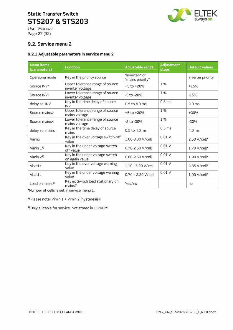
9.2.1 Adjustable parameters in service menu 2
Menu items (parameters)
Function Adjustable range Adjustment steps
Default values
Operating mode Key in the priority source “Inverter-“ or “mains priority”
Inverter priority
Source INV> Upper tolerance range of source inverter voltage +5 to +20% 1 % +15%
Source INV< Lower tolerance range of source inverter voltage -5 to -20% 1 % -15%
delay so. INV Key in the time delay of source INV 0.5 to 4.0 ms 0.5 ms 2.0 ms
Source mains> Upper tolerance range of source mains voltage +5 to +20% 1 % +20%
Source mains< Lower tolerance range of source mains voltage -5 to -20% 1 % -20%
delay so. mains Key in the time delay of source mains 0.5 to 4.0 ms 0.5 ms 4.0 ms
Vimax Key in the over voltage switch-off value 1.00-3.00 V/cell 0.01 V
2.50 V/cell*
Vimin 11) Key in the under voltage switch-off value 0.70-2.50 V/cell 0.01 V
1.70 V/cell*
Vimin 21) Key in the under voltage switch-on again value 0.60-2.50 V/cell 0.01 V
1.90 V/cell*
Vbatt> Key in the over voltage warning value 1.10 - 3.00 V/cell 0.01 V
2.35 V/cell*
Vbatt< Key in the under voltage warning value 0.70 – 2.20 V/cell 0.01 V
1.90 V/cell*
Load on mains2) Key in: Switch load stationary on mains? Yes/no no
*Number of cells is set in service menu 1. 1) Please note: Vimin 1 < Vimin 2 (hysteresis)! 2) Only suitable for service. Not stored in EEPROM!
Static Transfer Switch
STS207 & STS203 User Manual Page 28 (32)
©2011. ELTEK DEUTSCHLAND GmbH. Eltek_UM_STS207&STS203_E_R1.0.docx
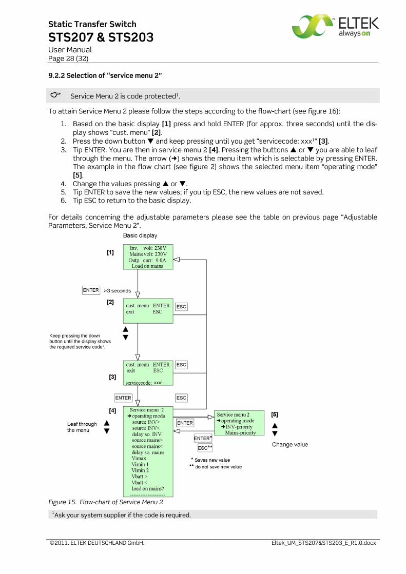
9.2.2 Selection of “service menu 2”
Service Menu 2 is code protected1.
To attain Service Menu 2 please follow the steps according to the flow-chart (see figure 16):
1. Based on the basic display [1] press and hold ENTER (for approx. three seconds) until the dis-play shows “cust. menu” [2].
2. Press the down button and keep pressing until you get “servicecode: xxx1” [3]. 3. Tip ENTER. You are then in service menu 2 [4]. Pressing the buttons or you are able to leaf
through the menu. The arrow () shows the menu item which is selectable by pressing ENTER. The example in the flow chart (see figure 2) shows the selected menu item “operating mode” [5].
4. Change the values pressing or . 5. Tip ENTER to save the new values; if you tip ESC, the new values are not saved. 6. Tip ESC to return to the basic display.
For details concerning the adjustable parameters please see the table on previous page “Adjustable Parameters, Service Menu 2”.
Figure 15. Flow-chart of Service Menu 2 1Ask your system supplier if the code is required.
Keep pressing the down button until the display shows the required service code1.
xxx1
Static Transfer Switch
STS207 & STS203 User Manual Page 29 (32)
©2011. ELTEK DEUTSCHLAND GmbH. Eltek_UM_STS207&STS203_E_R1.0.docx
10. Your notes
Static Transfer Switch
STS207 & STS203 User Manual Page 30 (32)
©2011. ELTEK DEUTSCHLAND GmbH. Eltek_UM_STS207&STS203_E_R1.0.docx
Your notes

Static Transfer Switch
STS207 & STS203 User Manual Page 31 (32)
©2011. ELTEK DEUTSCHLAND GmbH. Eltek_UM_STS207&STS203_E_R1.0.docx
Your notes

Supplier:
ELTEK DEUTSCHLAND GmbH BU Industrial Schillerstraße 16 D-32052 Herford
+ 49 (0) 5221 1708-210 FAX + 49 (0) 5221 1708-222 Email [email protected] Internet http://www.eltek.com
2011. ELTEK DEUTSCHLAND GmbH. All rights reserved.