Embed Size (px)
Citation preview

www. e n a i r . e s
E30
WIND TURBINE
USER MANUAL
PRO PRO
ENAIR ENERGY S.L.Avda de Ibi, Nº 44 - 03420 - Castalla
Aptdo Correos 182 - Alicante - SPAIN
Tel: +34 96 556 00 18
e-mail: [email protected]: www.enair.es

WIND TECHNOLOGY
+34 96 556 00 18 [email protected]
Avenida de Ibi 44 – P.O. 182-03420 | Castalla (Alicante), España www.enair.es P a g e | 2
Welcome and thank you for choosing ENAIR
You have acquired a w ind turbine for home and industrial use,excellent energy eff iciency and
manufactured w ith high quality materials.
If you have any comments or questions to us, please contact our Customer Service department
by writing to: [email protected]
In this manual you will find all the details of operation and maintenance of our wind turbines.
Please, prior to installing your wind turbine, read carefully the
paragraphs “5. INSTALLATION "and "9. WARRANTY”, there
you will find instructions to register your installation and the
warranty.
WIND TECHNOLOGY
+34 96 556 00 18 [email protected]
Avenida de Ibi 44 – P.O. 182-03420 | Castalla (Alicante), España www.enair.es P a g e | 3
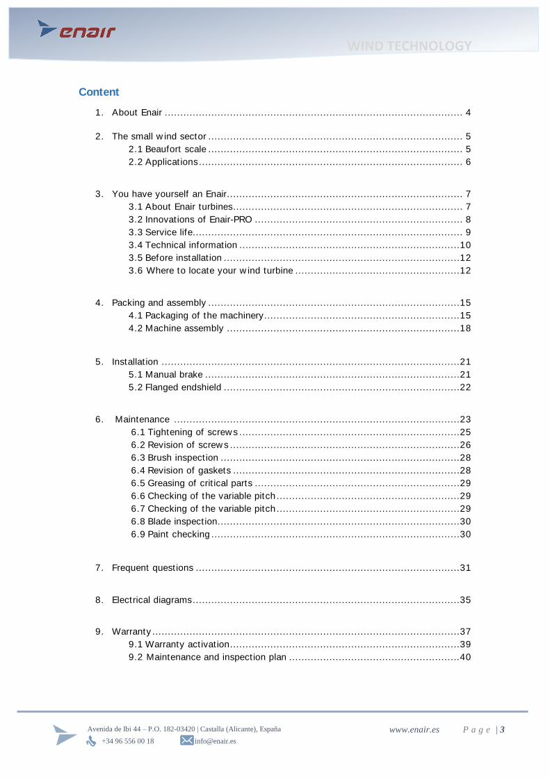
Content
1. About Enair ................................................................................................ 4
2. The small w ind sector .................................................................................. 5
2.1 Beaufort scale .................................................................................. 5
2.2 Applicat ions ..................................................................................... 6
3. You have yourself an Enair ............................................................................ 7
3.1 About Enair turbines .......................................................................... 7
3.2 Innovations of Enair-PRO ................................................................... 8
3.3 Service life ....................................................................................... 9
3.4 Technical information .......................................................................10
3.5 Before installat ion ............................................................................12
3.6 Where to locate your w ind turbine .....................................................12
4. Packing and assembly .................................................................................15
4.1 Packaging of the machinery ...............................................................15
4.2 Machine assembly ...........................................................................18
5. Installat ion ................................................................................................21
5.1 Manual brake ..................................................................................21
5.2 Flanged endshield ............................................................................22
6. Maintenance ............................................................................................23
6.1 Tightening of screw s .......................................................................25
6.2 Revision of screw s ..........................................................................26
6.3 Brush inspect ion .............................................................................28
6.4 Revision of gaskets .........................................................................28
6.5 Greasing of crit ical parts ..................................................................29
6.6 Checking of the variable pitch ...........................................................29
6.7 Checking of the variable pitch ...........................................................29
6.8 Blade inspect ion ..............................................................................30
6.9 Paint checking ................................................................................30
7. Frequent quest ions .....................................................................................31
8. Electrical diagrams ......................................................................................35
9. Warranty ...................................................................................................37
9.1 Warranty act ivat ion ..........................................................................39
9.2 Maintenance and inspect ion plan .......................................................40
WIND TECHNOLOGY
+34 96 556 00 18 [email protected]
Avenida de Ibi 44 – P.O. 182-03420 | Castalla (Alicante), España www.enair.es P a g e | 4
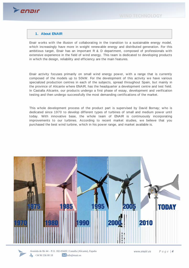
Enair w orks w ith the illusion of collaborat ing in the transit ion to a sustainable energy model,
w hich increasingly have more in w eight renew able energy and distributed generat ion. For this
ambit ious target, Enair has an important R & D department, composed of professionals w ith
extensive experience in the f ield of w ind energy. This team is dedicated to developing products
in w hich the design, reliability and eff iciency are the main features.
Enair act ivity focuses primarily on small w ind energy pow er, w ith a range that is current ly
composed of the models up to 50kW. For the development of this act ivity w e have various
specialized product ion centres in each of the subjects, spread throughout Spain, but mainly in
the province of Alicante w here ENAIR, has the headquarter a development centre and test f ield.
In Castalla Alicante, our products undergo a f irst phase of essay, development and verif icat ion
test ing and then undergo successfully the most demanding cert if icat ions of the market.
This w hole development process of the product part is supervised by David Bornay; w ho is
dedicated since 1970 to develop dif ferent types of turbines of small and medium pow er unt il
today. With innovative base, the w hole team of ENAIR is cont inuously incorporat ing
improvements to our turbines. According to recent market studies, w e believe that you
purchased the best w ind turbine, w hich in his power range, and market available is.
1. About ENAIR
WIND TECHNOLOGY
+34 96 556 00 18 [email protected]
Avenida de Ibi 44 – P.O. 182-03420 | Castalla (Alicante), España www.enair.es P a g e | 5
The small w ind turbine is regulated by the manufacturing standards of IEC-61400. Within
these standards are subcategories of the standard such as IEC-61400-2, -12, -11, etc.
each feature sets that small w ind turbines must comply w ith robustness, pow er curve,
noise, etc. requirements. Compliance w ith these rules is essential to ensure that a " small
w ind" has the quality required therein. At present there are very few countries w hich
require manufacturing standards for w ind turbine installat ions. Countries that do not
require these fulf ilments, are exposed to the opt ion that any type of home w ind turbine
w ithout safety and w arranty standards can be installed. This should be avoided as it
should be ensured that only product installat ions w ith high performance and reliability are
installed.
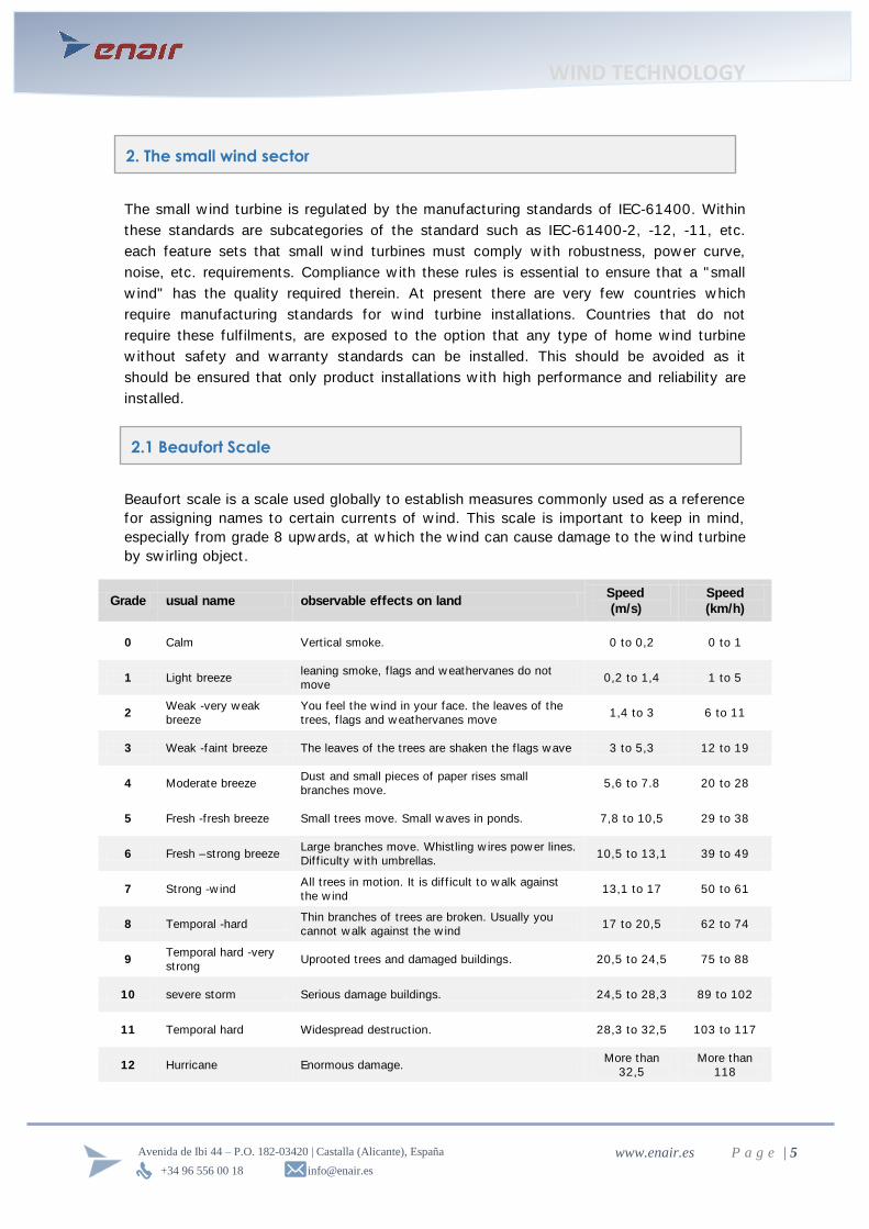
Beaufort scale is a scale used globally to establish measures commonly used as a reference
for assigning names to certain currents of w ind. This scale is important to keep in mind,
especially from grade 8 upw ards, at w hich the w ind can cause damage to the w ind t urbine
by sw irling object .
Grade usual name observable effects on land Speed
(m/s)
Speed
(km/h)
0 Calm Vert ical smoke. 0 to 0,2 0 to 1
1 Light breeze leaning smoke, f lags and w eathervanes do not
move 0,2 to 1,4 1 to 5
2 Weak -very w eak breeze
You feel the w ind in your face. the leaves of the
trees, f lags and w eathervanes move 1,4 to 3 6 to 11
3 Weak -faint breeze The leaves of the trees are shaken the f lags w ave 3 to 5,3 12 to 19
4 Moderate breeze Dust and small pieces of paper rises small
branches move. 5,6 to 7.8 20 to 28
5 Fresh -fresh breeze Small t rees move. Small w aves in ponds. 7,8 to 10,5 29 to 38
6 Fresh –strong breeze Large branches move. Whist ling w ires pow er lines.
Dif f iculty w ith umbrellas. 10,5 to 13,1 39 to 49
7 Strong -w ind All t rees in motion. It is dif f icult to w alk against
the w ind 13,1 to 17 50 to 61
8 Temporal -hard Thin branches of trees are broken. Usually you
cannot w alk against the w ind 17 to 20,5 62 to 74
9 Temporal hard -very
strong Uprooted trees and damaged buildings. 20,5 to 24,5 75 to 88
10 severe storm Serious damage buildings. 24,5 to 28,3 89 to 102
11 Temporal hard Widespread destruct ion. 28,3 to 32,5 103 to 117
12 Hurricane Enormous damage. More than
32,5
More than
118
2. The small wind sector
2.1 Beaufort Scale
WIND TECHNOLOGY
+34 96 556 00 18 [email protected]
Avenida de Ibi 44 – P.O. 182-03420 | Castalla (Alicante), España www.enair.es P a g e | 6
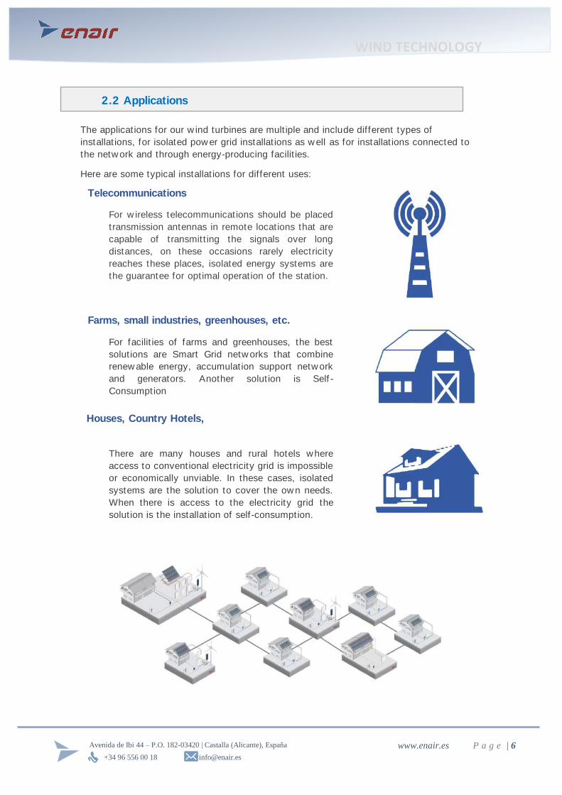
The applicat ions for our w ind turbines are mult iple and include different types of
installat ions, for isolated pow er grid installat ions as w ell as for installat ions connected to
the netw ork and through energy-producing facilit ies.
Here are some typical installat ions for different uses:
2.2 Applications
For w ireless telecommunicat ions should be placed
transmission antennas in remote locat ions that are
capable of transmitt ing the signals over long
distances, on these occasions rarely electricity
reaches these places, isolated energy systems are
the guarantee for opt imal operat ion of the stat ion.
For facilit ies of farms and greenhouses, the best
solut ions are Smart Grid netw orks that combine
renew able energy, accumulat ion support netw ork
and generators. Another solut ion is Self -
Consumption
There are many houses and rural hotels where
access to conventional electricity grid is impossible
or economically unviable. In these cases, isolated
systems are the solut ion to cover the ow n needs.
When there is access to the electricity grid the
solut ion is the installat ion of self-consumption.
Telecommunications
Farms, small industries, greenhouses, etc.
Houses, Country Hotels,

WIND TECHNOLOGY
+34 96 556 00 18 [email protected]
Avenida de Ibi 44 – P.O. 182-03420 | Castalla (Alicante), España www.enair.es P a g e | 7
ENAIR is a w ind turbine which belongs to the f ield of small w ind, simple operat ion and
easy assembly.
Target ing is done passively by a rudder that w orks as a w eathervane, he always keeps the
aero generator downw ind. Once the w ind impinges on the blades, the kinet ic energy of
w ind is transformed into rotat ional kinet ic energy. The variable pitch system regulates the
rotat ional speed for high w ind speeds. The generator converts this rotat ional kinet ic energy
into electrical energy.
Structurally the w ind turbine has: a main body, w hich provides the connect ion betw een the
coupling of the tow er, the helm orientat ion, generator and the variable pitch system, is
isolated from the outside by the cone piece, a housing protects the internal mechanism.
3. You have yourself an Enair
3.1 About the turbine ENAIR
Variable pitch
Blade Rudder Gondola
Cover
of Gondola
Back
cover
rotatable
Cone
WIND TECHNOLOGY
+34 96 556 00 18 [email protected]
Avenida de Ibi 44 – P.O. 182-03420 | Castalla (Alicante), España www.enair.es P a g e | 8
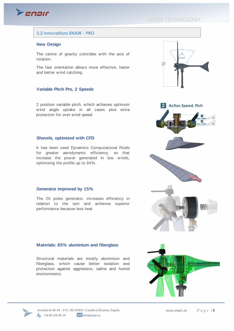
Shovels, optimized with CFD
It has been used Dynamics Computat ional Fluids
for greater aerodynamic efficiency, so that
increase the pow er generated in low w inds,
opt imizing the prof ile up to 94%.
Generator improved by 15%
The 20 poles generator, increases eff iciency in
relat ion to the rpm and achieves superior
performance because less heat
3.2 Innovations ENAIR - PRO
New Design
The centre of gravity coincides w ith the axis of
rotat ion.
The fast orientat ion allow s more effect ive, faster
and better w ind catching.
Variable Pitch Pro, 2 Speeds
2 posit ion variable pitch, w hich achieves opt imum
w ind angle uptake in all cases plus extra
protect ion for over w ind speed
Materials: 85% aluminium and fiberglass
Structural materials are mostly aluminium and
f iberglass, w hich cause better isolat ion and
protect ion against aggressive, saline and humid
environments.
WIND TECHNOLOGY
+34 96 556 00 18 [email protected]
Avenida de Ibi 44 – P.O. 182-03420 | Castalla (Alicante), España www.enair.es P a g e | 9
ENAIR has been designed for a service life of over 25 years, even in the most adverse
condit ions, such as extremely salty environments or locat ions w ith high average w ind
speeds.
UV resistance:
All paints used have high resistance to light and UV radiat ion to protect aging and fading
caused by the sun.
Resistance to high wind speeds:
The w ind turbine is designed to fully maintain its structural integrity for specif ic w ind
speeds of 60 m / s (216 km / h or 135 mph) (Class I according to IEC 614000-2 standard).
Is important to follow the safety recommendations show n in 4th point and the
maintenance planning show n in the 6th point .
Corrosion resistance:
Structural design w ith f iberglass and aluminium, as w ell as the applicat ion of surface
treatments allow the w ind turbine to be installed place w ith extreme condit ions: desert,
marine environments, etc.
To prevent corrosion of metal parts, specif ic naut ical paint ings are applied, based on
protect ive rubber.
Water-tightness:
The interior spaces are completely sealed to prevent moisture penetration that may
deteriorate internal components by placing a series of gaskets complete sealings.
Type of parts Corrosion Protection
Made of aluminium Anodized + ant icorrosion paint
Made of steel Anticorrosive paint or cataphoresis +
cataphoresis + galvanized + corrosion paint
Standard hardware elements AISI 316 stainless steel
Location of the joint Feature of the joint
Cone
Cancellous string EPDM 6mm Carcass
Back cover
3.3 Service Life
WIND TECHNOLOGY
+34 96 556 00 18 [email protected]
Avenida de Ibi 44 – P.O. 182-03420 | Castalla (Alicante), España www.enair.es P a g e | 10
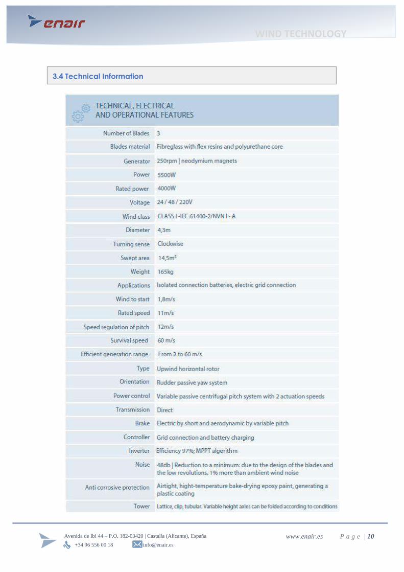
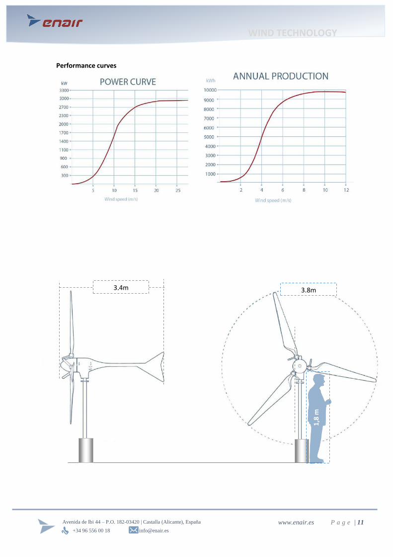
3.4 Technical Information
WIND TECHNOLOGY
+34 96 556 00 18 [email protected]
Avenida de Ibi 44 – P.O. 182-03420 | Castalla (Alicante), España www.enair.es P a g e | 11
Performance curves
3.8m 3,4m
1,8
m
WIND TECHNOLOGY
+34 96 556 00 18 [email protected]
Avenida de Ibi 44 – P.O. 182-03420 | Castalla (Alicante), España www.enair.es P a g e | 12
The ENAIR w ind turbine placement is as important as the available w ind.
The follow ing considerat ions should be taken into account:
Tower height:
In general, the produced pow er w ill be greater, as higher the tow er is because the w ind
speed increases w ith height. You must consider that a taller tow er is a major economic
investment w hich on the other hand is most often easily amort izable.
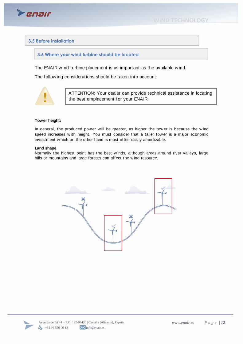
Land shape
Normally the highest point has the best w inds, although areas around river valleys, large
hills or mountains and large forests can affect the w ind resource.
3.5 Before installation
3.6 Where your wind turbine should be located
ATTENTION: Your dealer can provide technical assistance in locating
the best emplacement for your ENAIR.

WIND TECHNOLOGY
+34 96 556 00 18 [email protected]
Avenida de Ibi 44 – P.O. 182-03420 | Castalla (Alicante), España www.enair.es P a g e | 13
Obstructions:
Every obstacle that interferes the movement of the w ind is affect ing both its direct ion and
speed. The most common obstruct ions are houses and trees. It is generally recommended
to install the tow er 10 meters above any obstruct ion and w ith a distance tw ice the height
of the obstruct ion.
For example, if you have a house 5 meters tall and a tree 7 meters near w here you w ant to
install your ENAIR 30, it should be allocated to 17 meters above ground (7 m the highest
obstacle + 10 m) 10 meters from the house (5 x 2) and 14 meters from the tree (7 x 2).
Buildings:
On buildings, before placing a w ind turbine, ensure that the structure of the building can
w ithstand the w ind turbines w eight and stresses during its operat ion.
The w ind turbine should be placed about 3 meters back from the facade of the building,
and about 2-3 meters above the highest point. Consider also the surrounding buildings and
the “ w ind rose” .

WIND TECHNOLOGY
+34 96 556 00 18 [email protected]
Avenida de Ibi 44 – P.O. 182-03420 | Castalla (Alicante), España www.enair.es P a g e | 14
Areas where there is a clear direction of the prevailing wind:
In the environment of an obstacle an area of turbulence is produced.
Dimensions of turbulence area are def ined by the height of the object.
The Location is def ined by the direct ion of the prevailing w ind
The dimensions of the area of turbulence in the dow nw ind area (over 10H), are
condit ioned by the w idth of the object (A):
• If A <3H → Size of area downwind 20H • If A≤3H → Size of area downwind 10H (most common situation)
Prevailing winds:
It is important to know from w here the most frequent and strongest w inds come from, in
regarding of the area w here you w ant to install ENAIR 30. To the extent possible, this
direct ion must be free of obstruct ions. In order to know this, data is gathered w ith an
anemometer and a w ind vane to measure the direct ion and w ind speed over a period of
t ime. The outcome of the measurements is called "w ind rose" . An example of the
aforementioned w ind rose is show n below , the right show s the w ind situat ion in summer
and the left in w inter. As can be seen, they are completely dif ferent, so a detailed study of
the demand for electricity in both seasons w ill be very useful.
WIND TECHNOLOGY
+34 96 556 00 18 [email protected]
Avenida de Ibi 44 – P.O. 182-03420 | Castalla (Alicante), España www.enair.es P a g e | 15
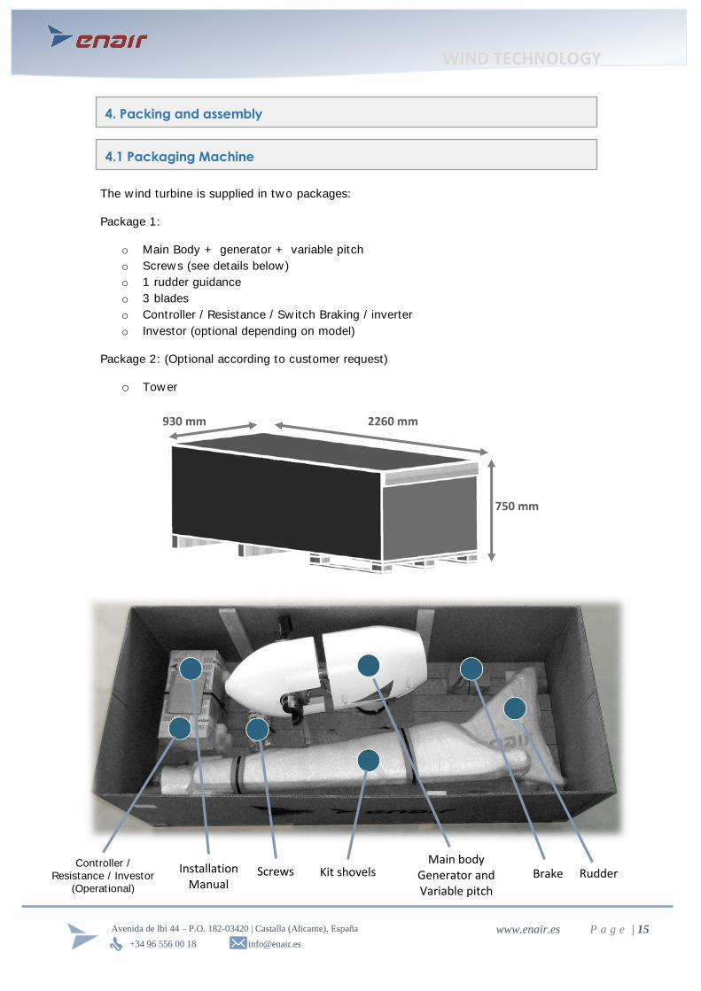
The w ind turbine is supplied in tw o packages:
Package 1:
o Main Body + generator + variable pitch
o Screw s (see details below)
o 1 rudder guidance
o 3 blades
o Controller / Resistance / Sw itch Braking / inverter
o Investor (opt ional depending on model)
Package 2: (Optional according to customer request)
o Tow er
2260 mm
750 mm
930 mm
Rudder Kit shovels Main body
Generator and Variable pitch
Screws Controller /
Resistance / Investor
(Operat ional)
4. Packing and assembly
4.1 Packaging Machine
Installation Manual
Brake

WIND TECHNOLOGY
+34 96 556 00 18 [email protected]
Avenida de Ibi 44 – P.O. 182-03420 | Castalla (Alicante), España www.enair.es P a g e | 16
List of parts:
- 3 blades
- 1 variable pitch
- 1 coupling: Variable pitch - generator
- 1 generator
- 1 main body
- 1 covering for the main body
- 1 rudder
- 1 coupling: axis of rotat ion – Tower
- 1 set of brushes
- 1 set of copper rings
Screw s:
The ENAIR is designed and built for easy, quick and safe installat ion.
If a bigger torque than recommended is applied, it can damage the parts connected by
those screw s.
If the applied torque is below the recommended, there is risk of vibrat ions.
Screws (metric x length) Joining pieces Tightening torque Quantity
M10 x 40 Rudder - gondola 46Nm / 34Lb.ft 6
M10 x 80 PMG - gondola 46Nm / 34Lb.ft 12
M14 x 60 Axis of rotation - Tower 127Nm / 93.5Lb.ft 8
M8 x 20 Cover - Gondola 5Nm / 3.5Lb.ft 4
M10 x 70 Counterweights - spoons 46Nm / 34Lb.ft 12
M10 x 50 Counterweights - spoons 46Nm / 34Lb.ft 3
M8 x 20 Brush- gondola 23Nm / 17Lb.ft 2
M14 x 60 Support variable pitch - axis PMG 127Nm / 93.5Lb.ft 1
M12 x 50 Base variable pitch - support PV 79Nm / 58Lb.ft 6
CAUTION: Apply the recommended values of pairs indicated in the table, use
torque meter wrenches to tighten them.
WIND TECHNOLOGY
+34 96 556 00 18 [email protected]
Avenida de Ibi 44 – P.O. 182-03420 | Castalla (Alicante), España www.enair.es P a g e | 17
SAFETY RECOMMENDATIONS
These safety recommendations should be taken into account during installat ion and during
maintenance of the ENAIR:
• ENAIR complies w ith internat ional safety standards, to ensure that your installat ion
should never be dangerous.
• ENAIR is designed so that the installat ion is safe, but there are common risks like w ith
any electromechanical equipment .
• ENAIR must be installed according to the instruct ions of this manual and in compliance
w ith local and nat ional standards.
• ENAIR installat ion must be performed by qualif ied professionals.
• During installation make sure that your wind turbine is braking (with the 3 phases short-
circuited) and disconnected from the electrical installation.
• Perform installat ion operat ions a calm day, the w ind should be less than 6 m / s.
• Never stand under the tow er during installat ion or maintenance operat ions.
• For safe installat ion at least tw o people are needed.
• During installat ion alw ays use proper safety equipment: helmet, safety shoes, gloves,
safety glasses …
ATTENTION: ENAIR is not responsible for the inappropriate use of the wind
turbine. The wind turbine should never be handled without the explicit
permission of the installer or manufacturer. Improper handling of the wind
turbine can result in electrocution and burns, and will be reasons for
cancellation of the guarantee.

WIND TECHNOLOGY
+34 96 556 00 18 [email protected]
Avenida de Ibi 44 – P.O. 182-03420 | Castalla (Alicante), España www.enair.es P a g e | 18
The w ind turbine assembly is divided into f ive simple steps. These steps should be
follow ed in the order show n below .
Step 1: Electrical connections
Step 2: Placement on the tower
Screws: Hexagonal screw bonding toe: DIN 933 M-14x55 INOX A2
8
Pressure w asher screw M14 bonding.: DIN 127 zinc plated
8
Washers screw union: DIN 125 M14 zinc plated
16
Binding screw nut: DIN 934 M14 INOX A2
8
Tools: 22 spanner, hexagonal of 22 and torque w rench
Tightening torque: 127 Nm oder 93.5 Lbf.f t
4.2 Installing the machine
Join the three electrical connectors from the brushes
w ith the cables installed in the tow er.
To prevent that the w eight of the connected cables pulls
on the brushes, they should be w inded three t imes
around a prepared w elded part at the top of the tower.

WIND TECHNOLOGY
+34 96 556 00 18 [email protected]
Avenida de Ibi 44 – P.O. 182-03420 | Castalla (Alicante), España www.enair.es P a g e | 19
Step 3: Shovels
To ensure proper assembly of the blades, there is a protrusion on the blade that
should f it w ith the corresponding hole in the conical scoop.
Screws: Allen screw scoop-holder: DIN 912 A2 M10x80 INOX 12
Allen screw scoop-holder: DIN 912 A2 M10x80 INOX 3
Pressure Washers screw union: DIN 127 M-10 zinc plated 15
Tools: 17 spanner, hexagonal of 17 and torque wrench
Tightening torque : 46 Nm oder 34 Lbf.ft
ATTENTION: By tightening, there must remain a small clearance between the
bucket and the counterweight
ATTENTION: When the tightening is done some crunches could be heard. This
is absolutely normal and needed this guarantees the optimal fixing of the blade

WIND TECHNOLOGY
+34 96 556 00 18 [email protected]
Avenida de Ibi 44 – P.O. 182-03420 | Castalla (Alicante), España www.enair.es P a g e | 20
Step 4: Rudder
Step 5: Upper casing
Screw s:
Allen screw clamp: DIN 912 A2 M10x55 INOX 6
Clamp pressure Washers: DIN 127 M-10 zinc plated 6
Clamp Washers: DIN 125 M-10 zinc plated 6
Tools: Allen glass 8, extension cable and torque w rench
Tightening torque: 46 Nm oder 34 Lbf.ft
Screws: Allen screw casing: DIN 912 M8x25 A2 STAINLESS 4
casing pressure Washers: DIN 127 M7 zinc plated 4
casing Washers: DIN 125 M8 zinc plated 4
Tools:
Glass Allen 8, extension cable and torque w rench
Tightening torque : 5Nm or 3.7Lbf.f t
ATTENTION: By tightening, there must remain a small clearance between the
clamp and the nacelle
WIND TECHNOLOGY
+34 96 556 00 18 [email protected]
Avenida de Ibi 44 – P.O. 182-03420 | Castalla (Alicante), España www.enair.es P a g e | 21
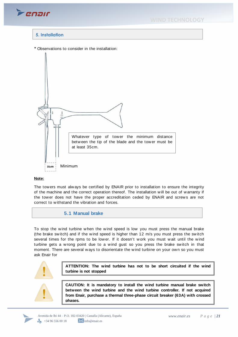
* Observat ions to consider in the installat ion:
Note:
The towers must alw ays be cert if ied by ENAIR prior to installat ion to ensure the integrity
of the machine and the correct operat ion thereof. The installat ion w ill be out of w arranty if
the tow er does not have the proper accreditat ion ceded by ENAIR and screw s are not
correct to w ithstand the vibrat ion and forces.
To stop the w ind turbine w hen the w ind speed is low you must press the manual brake
(the brake sw itch) and if the w ind speed is higher than 12 m/s you must press the sw itch
several t imes for the rpms to be low er. If it doesn' t w ork you must w ait unt il the w ind
turbine gets a w rong point due to a w ind gust so you press the brake sw itch in that
moment. There are several w ays to disorientate the w ind turbine on your own so you must
ask Enair for
5. Installation
Whatever type of tower the minimum distance
betw een the t ip of the blade and the tow er must be
at least 35cm.
35cm Minimum
m
5.1 Manual brake
CAUTION: It is mandatory to install the wind turbine manual brake switch
between the wind turbine and the wind turbine controller. If not acquired
from Enair, purchase a thermal three-phase circuit breaker (63A) with crossed
phases.
ATTENTION: The wind turbine has not to be short circuited if the wind
turbine is not stopped

WIND TECHNOLOGY
+34 96 556 00 18 [email protected]
Avenida de Ibi 44 – P.O. 182-03420 | Castalla (Alicante), España www.enair.es P a g e | 22
For customers w ho have their ow n tow er, below there is the coupling plane between the
rotat ion axis of ENAIR 30PRO and tow er. This coupling must be w elded to the top of the
tow er and bolted to the axis of rotat ion of the turbine.
Screw: Quality 8.8 zinc plated M14x50mm
The tow er must w ithstand 1000 kg at peak and load for the follow ing data for the design:
* The data provided has been obtained in accordance w ith IEC 61400-2 and does not
include safety factors.
The straps w elding head of the tow er must be clean so that contact w ith the toe is good
and vibrat ions are not produced.
The connect ion betw een the top of the tower and the bottom of the w ind turbine has to be
done as such that the bolts can w ithstand the forces and moments calculated for the
w hole w ind turbine + tow er.
Screw : 8.8 galvanized M20x55 w ith 2 w ashers and lock nut M20
ENAIR Weight Thrust Overturning moment
E30PRO* 125 kg 3350 N 1350 Nm
5.2 Coupling flange and tower
WIND TECHNOLOGY
+34 96 556 00 18 [email protected]
Avenida de Ibi 44 – P.O. 182-03420 | Castalla (Alicante), España www.enair.es P a g e | 23
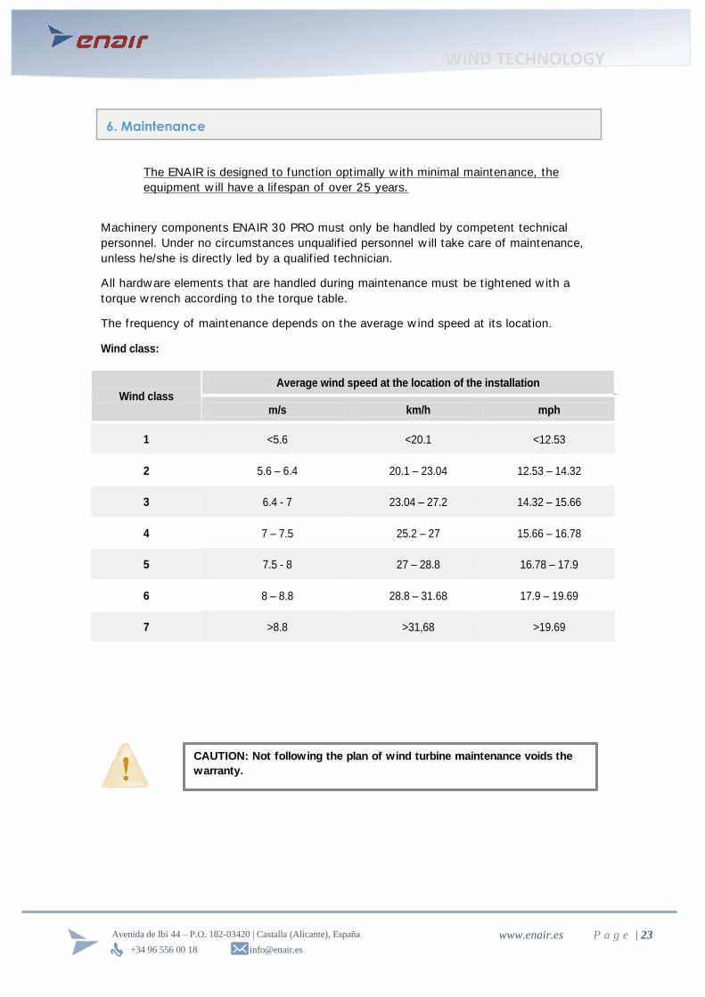
The ENAIR is designed to funct ion opt imally w ith minimal maintenance, the
equipment w ill have a lifespan of over 25 years.
Machinery components ENAIR 30 PRO must only be handled by competent technical
personnel. Under no circumstances unqualif ied personnel w ill take care of maintenance,
unless he/she is direct ly led by a qualif ied technician.
All hardw are elements that are handled during maintenance must be t ightened w ith a
torque w rench according to the torque table.
The frequency of maintenance depends on the average w ind speed at its locat ion.
Wind class:
Wind class Average wind speed at the location of the installation
m/s km/h mph
1 <5.6 <20.1 <12.53
2 5.6 – 6.4 20.1 – 23.04 12.53 – 14.32
3 6.4 - 7 23.04 – 27.2 14.32 – 15.66
4 7 – 7.5 25.2 – 27 15.66 – 16.78
5 7.5 - 8 27 – 28.8 16.78 – 17.9
6 8 – 8.8 28.8 – 31.68 17.9 – 19.69
7 >8.8 >31,68 >19.69
6. Maintenance
CAUTION: Not following the plan of wind turbine maintenance voids the
warranty.

WIND TECHNOLOGY
+34 96 556 00 18 [email protected]
Avenida de Ibi 44 – P.O. 182-03420 | Castalla (Alicante), España www.enair.es P a g e | 24
Preventive maintenance plan:
Wind class 1 2 3 4 5 6 7
Tighten screw of blades, rudder axis
of rotat ion, toe and tow er. A month after installation
Visual inspect ion (both Windmill and
the tow er), check for abnormal
noise and vibrat ion
A month after installat ion and after storms or w inds exceeding 25 m /
s (90 km / h, 56 mph)
1 - Tighten screw s rudder axis of
rotat ion and toe
Every 12 months Every 8 months
2 - Tighten screw s other tower (e.g.
joints, couplings ...)
3 - Greasing bearings in the variable
pitch
4 - Greasing the w hole variable
pitch
5 - Checking the status of the
blades, special attent ion to the
leading edge
6 - Checking the correct operat ion
of the variable pitch
7 - Checking paint, search for
damage and rust spots
8 - Inspect ing the carbon brushes,
slip rings and connect ing cables
9 - Replacing carbon brushes Every 15 years (indicative) Every 10 years ( indicat ive)
CAUTION: Do not follow the plan of wind turbine maintenance voids the
warranty.

WIND TECHNOLOGY
+34 96 556 00 18 [email protected]
Avenida de Ibi 44 – P.O. 182-03420 | Castalla (Alicante), España www.enair.es P a g e | 25
Step 1: Remove Cone
To perform maintenance operat ions, it w ill be necessary to remove the cone and the rear
cover.
Step 2: Visual Inspection interior elements
To remove the cone, you can use any w rench or
any elongated object that f its into the screw slot.
To loosen, torque in the opposite direction of the
usual loosening must be applied.
Visually verify that there are no loose parts and
everything is properly screw ed.
Check slackness of parts, simply by moving w ith
hand.
All screws should be tightened and parts must not
show slackness.
CAUTION: Before performing any maintenance, stop the mill, using the
braking contactor.
CAUTION: Attach one of the blades of the ENAIR to the lift
basket to prevent rotation of the rotor during maintenance
operations.
CAUTION: Do not perform any maintenance operation in high winds
situations.

WIND TECHNOLOGY
+34 96 556 00 18 [email protected]
Avenida de Ibi 44 – P.O. 182-03420 | Castalla (Alicante), España www.enair.es P a g e | 26
Step 3: tighten up the indicated screws.
Slide guide
Variable-pitch coupling plate
Counter-weights
Rudder
3x DIN912 – M10 x 35
Tools:
Allen wrench and torque wrench 8
Tightening torque: 46 Nm or 33 Lbf.ft
6 x DIN931 – M12 x 50
6 x DIN985 – M12 Nut
Tools: end spanner 19, 19 hexagonal socket,
extension and torque wrench
Tightening torque: 62 Nm or 46 Lbf.ft
4 x DIN912 – M10 x 80
1 x DIN912 – M10 x 50
Tools: Wrench and torque w rench 8
Tightening torque: 46 Nm or 33 Lbf.f t
6 x DIN912 – M10 x 50
Tools: Wrench and torque w rench 8
Tightening torque : 46 Nm or 33 Lbf.f t
With the proper tool, verify the indicated t ightness
of the screw s.

WIND TECHNOLOGY
+34 96 556 00 18 [email protected]
Avenida de Ibi 44 – P.O. 182-03420 | Castalla (Alicante), España www.enair.es P a g e | 27
Rotable
Toecap
Tools: 22 end spanner, hexagonal of 22 and torque
w rench
Tightening: 91 Nm or 67 Lbf.f t
Tools: 22 end spanner, hexagonal of 22 and torque
w rench
Tightening: 91 Nm or 67 Lbf.f t
In case of using a latt ice tow er installat ion, you
must also check its screws.
WARNING: It is also important to check the electrical
connections on the charge controller, batteries, inverter and
resistors.
WIND TECHNOLOGY
+34 96 556 00 18 [email protected]
Avenida de Ibi 44 – P.O. 182-03420 | Castalla (Alicante), España www.enair.es P a g e | 28
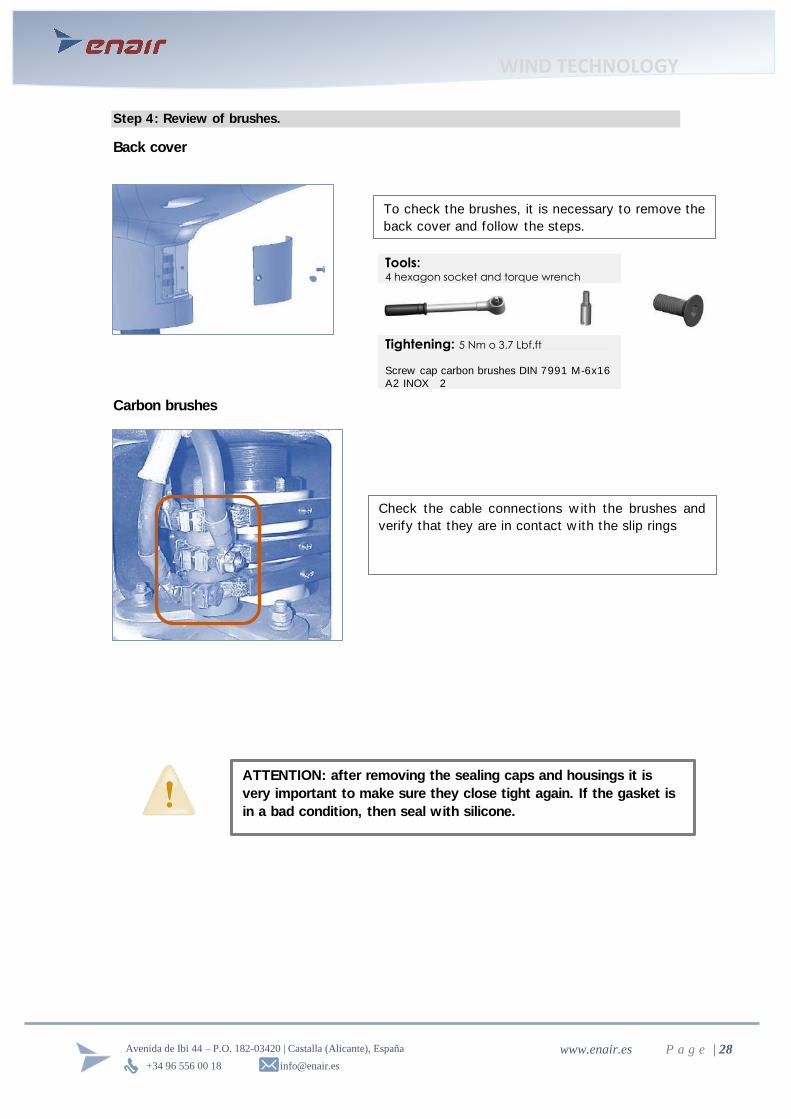
Step 4: Review of brushes.
Back cover
Carbon brushes
Tools: 4 hexagon socket and torque wrench
Tightening: 5 Nm o 3.7 Lbf.ft
Screw cap carbon brushes DIN 7991 M-6x16
A2 INOX 2
To check the brushes, it is necessary to remove the
back cover and follow the steps.
ATTENTION: after removing the sealing caps and housings it is
very important to make sure they close tight again. If the gasket is
in a bad condition, then seal with silicone.
Check the cable connect ions w ith the brushes and
verify that they are in contact w ith the slip rings

WIND TECHNOLOGY
+34 96 556 00 18 [email protected]
Avenida de Ibi 44 – P.O. 182-03420 | Castalla (Alicante), España www.enair.es P a g e | 29
Step 5: Greasing critical parts.
Type of grease: Lubricat ing grease for extreme pressure and high temperatures.
Physical characteristics of grease
Texture Filiform
Colour blue green or brow n
Classification NL6Z Grade 2
(60 cycles) worked penetration 280 1/10 mm
Dropping point 230 0C
Source soap aluminum complex
Bearing
Step 6: Checking the Variable pitch.
Check that the bearing is greased and add
in the event of absence.
This must be done in each of the rolling
bearing of the blades.
1. Press w ith tw o persons the three torque levers simultaneously, resistant spring force must
be not iceable
2. The levers must reach the limit posit ion.
3. Releasing the levers, should cause a return to their init ial posit ion
WIND TECHNOLOGY
+34 96 556 00 18 [email protected]
Avenida de Ibi 44 – P.O. 182-03420 | Castalla (Alicante), España www.enair.es P a g e | 30
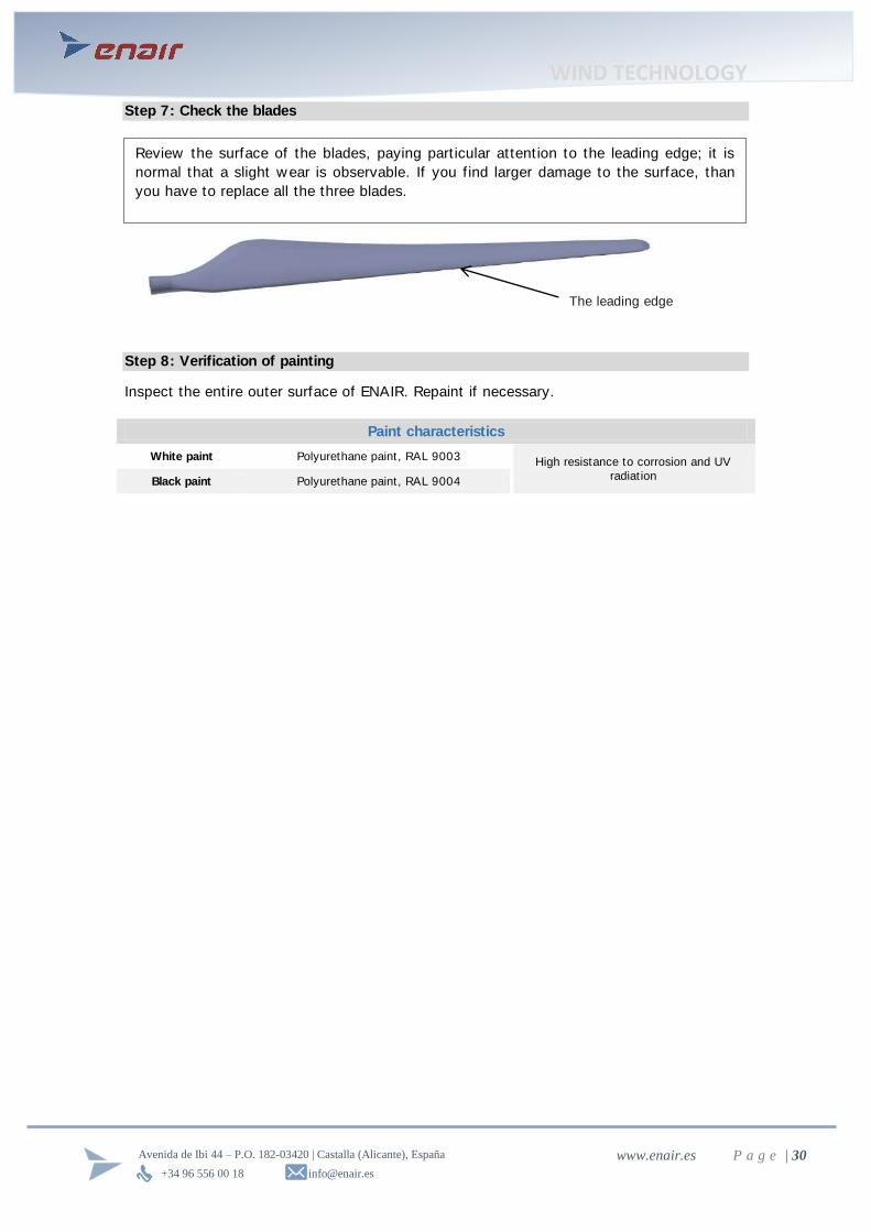
Step 7: Check the blades
Step 8: Verification of painting
Inspect the ent ire outer surface of ENAIR. Repaint if necessary.
Paint characteristics
White paint Polyurethane paint, RAL 9003 High resistance to corrosion and UV
radiat ion Black paint Polyurethane paint, RAL 9004
The leading edge
Review the surface of the blades, paying part icular attent ion to the leading edge; it is
normal that a slight w ear is observable. If you f ind larger damage to the surface, than
you have to replace all the three blades.

WIND TECHNOLOGY
+34 96 556 00 18 [email protected]
Avenida de Ibi 44 – P.O. 182-03420 | Castalla (Alicante), España www.enair.es P a g e | 31
1. What is the right size for my installation?
The follow ing table shows a guide to w hich w ind turbine chosen depending on the
w ind and electricity consumption. For reference, a normal household consumes
about 4000kWh annually, w hile a large consumer can be about 6000 or
15000kWh.
For Wind Turbine model suitable for installat ion have the eCon application of
calculat ion and design of facilit ies in 4 steps that w ill recommend the most
appropriate model for you. w w w .enair.es/app
2. Why install a Horizontal Axis Wind Turbine and 3 blades instead of other designs?
Horizontal 3-blade w ind turbines offer the highest eff iciency based on their design
and the Betz Law , which def ines the maximum theoret ical conversion factor
betw een the energy carried by the w ind to pow er absorbed by the turbine blades.
This conversion factor is the pow er coeff icient Cp Wind Turbine, and its maximum
value is Cp = 0.59, precisely by the Law of Betz.
Each type of w ind turbine design, w hether 2-blade or mult iblade vert ical axis have
dif ferent coeff icients limited by the design of the w ind turbine itself . In the
follow ing table you can see these coeff icients.
As show n in the chart, the best design according to physical law s is the 3-blade
model horizontal w ind turbine. This is the most common and w idespread design
w orldw ide.
7. Frequently Asked Questions

WIND TECHNOLOGY
+34 96 556 00 18 [email protected]
Avenida de Ibi 44 – P.O. 182-03420 | Castalla (Alicante), España www.enair.es P a g e | 32
3. How much space do I need?
In theory, a w ind turbine w orks better w hen less obstacles are in the path of the
w ind, but w ith a suff icient distance from the obstacles, the effect can be
minimised.
A w ind turbine should be place at a horizontal distance of at least tw ice the height
of the closest obstacles and at least 10m higher than the closest obstacles. For
further explanations, please consult the chapter “ Installat ion” .
4. Are Wind turbines noisy?
The ENAIR w ind turbines are designed to be silent as its rated speed is betw een
200 and 250rpm depending on the model. Considering the height at w hich they
are, they w ill be virtually unnoticeable by someone w ho is standing at its base.
Having a 33% low er rpm than other exist ing w ind turbines, it makes the longevity
3 t imes higher than the high-revving models.
5. Birds affect small wind turbines?
It is unlikely that a bird impacts the blades of a small w ind turbine as ENAIR,
rotat ing at low speed (betw een 200 and 250 rpm depending on the model) and not
located at the height to w hich migratory birds make their long journeys, w hich
makes it even more unlikely.
6. Can I use a wind generator for my heating system?
Yes, you can use a w ind turbine to heat w ater. Simply connect the controller
output to an electric heater. What you should consider is that normally the heating
energy consumption is considerably higher than electricity, so you w ill need to
have larger equipment.
7. Can I connect my equipment to the network?
Small w ind turbines themselves can be connected to the distribut ion netw ork. This
requires using a compatible inverter w ith the netw ork and that the installat ion is
approved by the local ut ility company, w hich require compliance w ith the standards
and regulat ion w ith which a connect ion to the grid can be built .
Each model of our turbines has been tested for this purpose in period of one year,
w ith a very good result.
8. The tower swings, is normal?
When the tow ers are not provided by Enair could sw ing due to the coupling
betw een resonance frequencies. Because of the w ind turbine is a dynamic system
w hen the natural frequencies of the tower couple w ith the rotat ional frequencies of
the w ind turbine then the tow er begin to sw ing and it depends on the tow er type,
the w ind turbine... if the oscillat ions are bigger t han the 2% of the tow er height
and they don' t dissapear contact Enair

WIND TECHNOLOGY
+34 96 556 00 18 [email protected]
Avenida de Ibi 44 – P.O. 182-03420 | Castalla (Alicante), España www.enair.es P a g e | 33
9. How long does a wind turbine work?
Our w ind turbines are designed to last more than 20 years. This is due to its robust
design, quality of materials, the anti-corrosion treatments and a completely sealed
design that prevents moisture and other part icles from entering the system and the
inability of the birds nest ing in them during w indless periods.
All this means that our design does not deteriorate even in aggressive
environments like near the sea, w here saline air and the sand part icles usually
cause corrosion and erosion.
10. Can I have my own wind turbine?
Small w ind turbines are the perfect choice for individuals, communit ies and small
businesses that w ant to generate their ow n energy. The chosen characterist ics of
the locat ion (average w ind speed, locat ion and topography) determine the size and
type of w ind turbine used in each case
11. How do I know if I have enough wind?
The w ind speed is inf luenced by the local topography and nearby obstacles such as
trees and buildings. Wind direct ion sometimes can be very variable w ith risk of
being affected by turbulence due to the nearby obstacles. So w hen in doubt , it is
best to contact professionals engaged in the installat ion of small w ind turbines.
Normally, w ith an average of 5 m / s it is w orthw hile installing a small w ind
turbine.
Our technical department w ill inform you about the average speed at your
part icular locat ion. In order to do this, please f ill in the contact form on:
www.enair.es
12. How does a wind turbine produce electricity?
Roughly a w ind turbine w orks as follow s: the blades take advantage of w ind
energy to generate a torque on the generator. This, depending on the speed and
the force exerted by the blades and its axis, generate electricity, w hich w ill reach
the controller and the inverter. These electronic components convert electricity
cont inuously for w hatever purpose its needed like charging batteries, direct
consumption or feeding electricity to the grid.
13. How tall is a small wind turbine?
The tow er height can vary considerably, depending on the type of turbine and the
locat ion. Generally, the tow er of small w ind turbines ranges from 10 to 20m. The
higher the tow er, the more constant and faster are the w inds.
Furthermore, to determine the total height of the system, one must take into
account the diameter of the blades, w hich typically ranges betw een 1.5 and 10m.
WIND TECHNOLOGY
+34 96 556 00 18 [email protected]
Avenida de Ibi 44 – P.O. 182-03420 | Castalla (Alicante), España www.enair.es P a g e | 34
14. I need some kind of permission to install my wind turbine?
The installat ion of small w ind turbines may require some kind of permission. This
often depends on the height of the tow er, the autonomous region or the country in
w hich you w ant to install. When in doubt it is best to consult a professional or the
competent authority in each case.
15. What materials are used in the ENAIR?
The structural parts of our w ind turbines are made of stainless steel and aluminium.
Blades and other components are made of copper, plast ic, polyester resin and
f iberglass.
All parts are adequately protected against corrosion, either by hot dip galvanizing or
by various surface treatments aimed to have adequate protect ion even in salty
environments. Furthermore, the ent ire assembly is sealed to prevent ingress of
w ater, dust or any kind of substance inside. In this w ay the electrical components
are safe and w ell protected.
WIND TECHNOLOGY
+34 96 556 00 18 [email protected]
Avenida de Ibi 44 – P.O. 182-03420 | Castalla (Alicante), España www.enair.es P a g e | 35
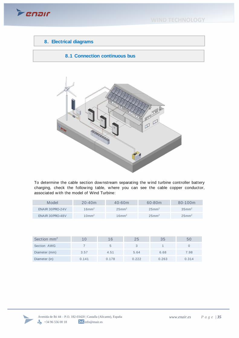
To determine the cable sect ion dow nstream separat ing the w ind turbine controller battery
charging, check the follow ing table, w here you can see the cable copper conductor,
associated w ith the model of Wind Turbine:
Model 20-40m 40-60m 60-80m 80-100m
ENAIR 30PRO-24V 16mm2 25mm2 25mm2 35mm2
ENAIR 30PRO-48V 10mm2 16mm2 25mm2 25mm2
Section mm2 10 16 25 35 50
Section AWG 7 5 3 1 0
Diameter (mm) 3.57 4.51 5.64 6.68 7.98
Diameter (in) 0.141 0.178 0.222 0.263 0.314
8. Electrical diagrams
8.1 Connection continuous bus
WIND TECHNOLOGY
+34 96 556 00 18 [email protected]
Avenida de Ibi 44 – P.O. 182-03420 | Castalla (Alicante), España www.enair.es P a g e | 36
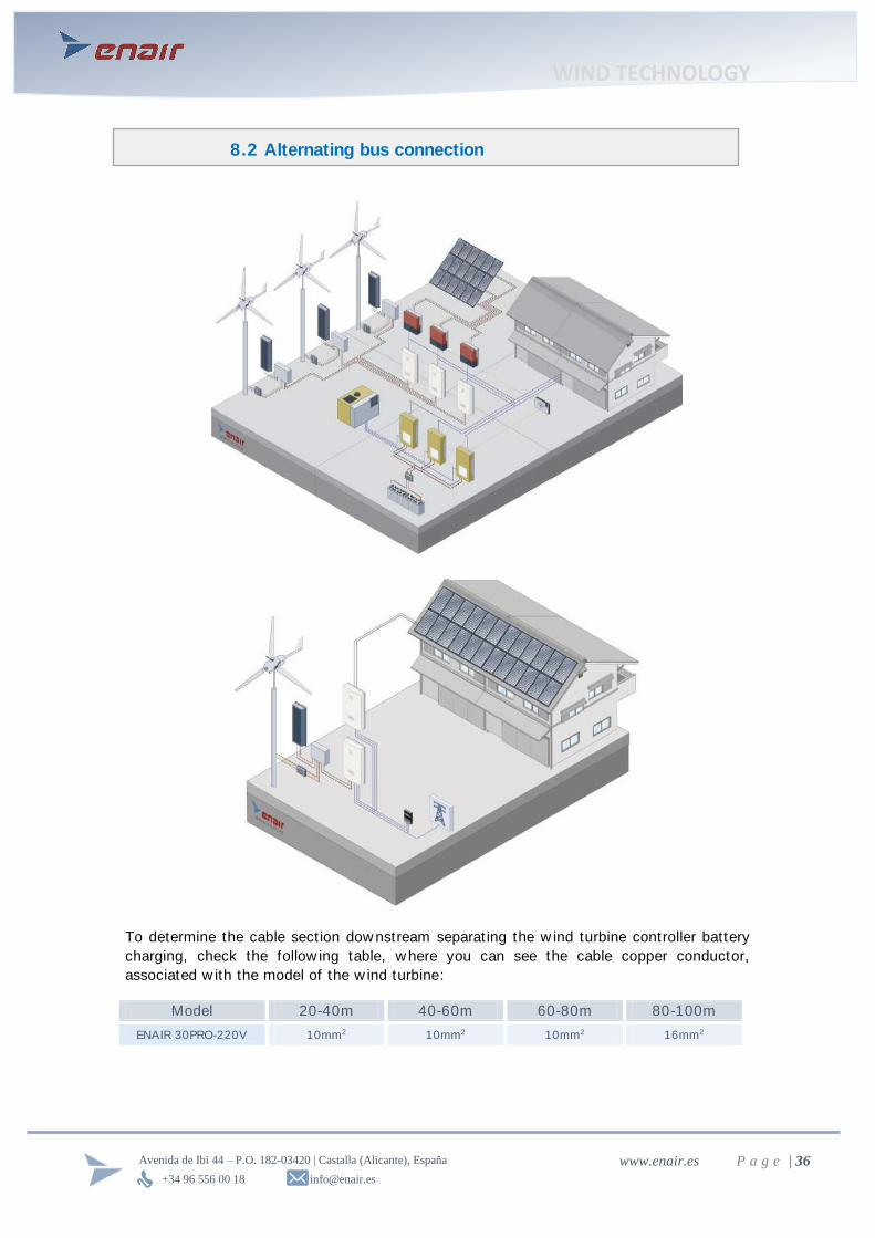
To determine the cable sect ion dow nstream separat ing the w ind turbine controller battery
charging, check the follow ing table, w here you can see the cable copper conductor,
associated w ith the model of the w ind turbine:
Model 20-40m 40-60m 60-80m 80-100m
ENAIR 30PRO-220V 10mm2 10mm2 10mm2 16mm2
8.2 Alternating bus connection
WIND TECHNOLOGY
+34 96 556 00 18 [email protected]
Avenida de Ibi 44 – P.O. 182-03420 | Castalla (Alicante), España www.enair.es P a g e | 37
LIMITED WARRANTY CONDITIONS
ENAIR ENERGY SL ensures that the ENAIR w ind turbines are free from defects in material
and w orkmanship for a period of 48 months from the date of purchase or 60 months from
the manufacture of that product, under normal and individual use proper installat ion,
commissioning and periodic maintenance.
The w arranty covers repair or replacement of damaged parts and labour in our w orkshops.
EXCLUSIONS AND LIMITATIONS OF WARRANTY
This w arranty shall not apply if the client or user previously not been returned duly
completed w arranty card. The w arranty does not cover w ind turbines that have not passed
the periodic maintenance indicated in the manual and is properly sealed.
Generally, they are exempt from the guarantee rights established herein, damage and
malfunct ions or service of w ind turbines ENAIR originat ing in:
1) Negligent, improper or inappropriate use of the product .
2) Failure to observe the instruct ions for installat ion, use, maintenance and periodic
review s established in the equipment manual, and technical and safety rules in
force, local, nat ional or internat ional standing, w hich w ere applicable at any t ime
(Electrotechnical Regulation of Low voltage, and Technical Instruct ions,
electromagnetic compatibility, etc.)
3) Manipulat ions performed by unqualif ied personnel. Understood by staff competent
professionals w ith experience in electrical installat ions, companies engaged in
distribut ion, sale or installat ion of RES.
4) Damage caused by natural disasters (f loods, plagues, earthquakes, hurricanes,
cyclones, tornadoes, lightning, hail, f ires ...), vandalism, act ions of third part ies or
any other force majeure outside the normal operating condit ions of the equipment
and control of ENAIR ENERGY S.L.
5) Impact of f lying objects coming or majeure force.
6) Torre or structural failure w hen not furnished by ENAIR ENERGY S.L.
7) 1) Products that have not been paid in full.
9. Warranty

WIND TECHNOLOGY
+34 96 556 00 18 [email protected]
Avenida de Ibi 44 – P.O. 182-03420 | Castalla (Alicante), España www.enair.es P a g e | 38
Intervent ion costs arising from dismantling the faulty equipment or the subsequent
reinstallat ion of equipment parts w arranty rights established herein do not cover
transportat ion costs of w ind turbines or defect ive items, of returning to ENAIR ENERGY
S.L. It does not cover, also.
ENAIR ENERGY S.L w e reserve the right to supply a dif ferent model of w ind turbine or
component to resolve claims accepted under guarantee, as a replacement and if the
original model is no longer manufactured. In this case, the new model w ill be of equal or
higher performance.
ENAIR ENERGY S.L it undertakes to make use of the obligat ions described in the
condit ions of this Limited Warranty, and in the event of repair or replacement of default
attributable to the manufacturer, cover the transport costs of the subsequent return to the
address registered customer and have them available w ithin a maximum period of 60 days
from the date of receipt .
Si ENAIR ENERGY S.L w ere to determine that the problem of the w ind turbine is not due to
a defect in materials and w orkmanship, then the Customer shall bear the costs of test ing
and processing generated.
Defect ive complained Products w hich do not meet the specif icat ions w ill become the
property of ENAIR ENERGY S.L., as soon as they have been replaced or paid.
Any return of material and replacement by ENAIR ENERGY SL under w arranty condit ions,
const itute full sett lement and release of all subsequent claims of any person covered by
damages or other relief , and w ill be an impediment to any I dispute subsequently presented
to the person w ho accepts an agreement of this type.
LIMITATION OF LIABILITY
ENAIR ENERGY S.L it w ill not be liable to the customer, direct ly or indirect ly, for any
failure or delay in the implementat ion of its w arranty obligat ions, w hich may be caused by
majeure force or any other unforeseen incident to the w ill of ENAIR ENERGY S.L.
ENAIR responsibility for ENERGY S.L. arising from this Guarantee Cert if icate is limited to
the obligat ions expressed above, expressly excluding any liability for consequential
damages such as loss of income or operat ing prof its.
When the subject of the claim is the result of improper installat ion, ENAIR ENERGY S.L.
shall be liable only w hen explicit ly that installat ion w as part of the scope of supply of the
sales contract .
Any other security that is not expressly mentioned in this cert if icate is excluded.

WIND TECHNOLOGY
+34 96 556 00 18 [email protected]
Avenida de Ibi 44 – P.O. 182-03420 | Castalla (Alicante), España www.enair.es P a g e | 39
To act ivate the guarantee you have to enter the follow ing w eb
https://w w w .enair.es/garant ia and access w ith the serial number that appears in the
manual of the w ind turbine.
It is necessary to f ill in the user' s data in order to inform you when to carry out the
preventive maintenance
Once the w arranty is act ivated, the mechanical parts of the w ind turbine w ill have a 4 -year
guarantee from the invoice date or 5 years from the date of manufacture. The w arranty of
the associated electronics is 2 years from invoice date
9.1 Warranty activation
WIND TECHNOLOGY
+34 96 556 00 18 [email protected]
Avenida de Ibi 44 – P.O. 182-03420 | Castalla (Alicante), España www.enair.es P a g e | 40
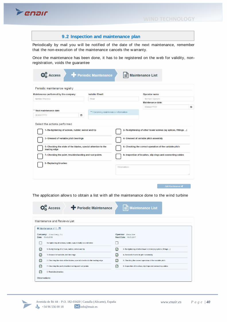
Periodically by mail you w ill be not if ied of the date of the next maintenance, remember
that the non-execution of the maintenance cancels the w arranty.
Once the maintenance has been done, it has to be registered on the w eb for validity, non-
registrat ion, voids the guarantee
The applicat ion allow s to obtain a list w ith all the maintenance done to the w ind turbine
9.2 Inspection and maintenance plan