Embed Size (px)
Citation preview

This manual MUST be given to the user of the product.
BEFORE using this product, read this manual and save for future refe
Invacare®9000 Topaz™Wheelchair
User Manual
rence.
EN

© 2015 Invacare Corporation. All rights reserved. Republication, duplication or modification in whole or in part is prohibited without prior written permission from Invacare. Trademarks are identified by ™ and ®. All trademarks are owned by or licensed to Invacare Corporation or its subsidiaries unless otherwise noted.
Invacare®9000 Topaz™Wheelchair 2 Part No 1100869

CONTENTS
1 GENERAL 6
Symbols .................................................................................................................................................................................................................................................... 6Limited Warranty .................................................................................................................................................................................................................................. 7
2 OVERVIEW 8
Label Location......................................................................................................................................................................................................................................... 8Component Identification .................................................................................................................................................................................................................... 9Specifications......................................................................................................................................................................................................................................... 10
3 SAFETY 11
General Guidelines .............................................................................................................................................................................................................................. 11Intended Use......................................................................................................................................................................................................................................... 12Wear and Tear Items.......................................................................................................................................................................................................................... 13Repair and Service Information ........................................................................................................................................................................................................ 13Operating Information.........................................................................................................................................................................14Safety/Handling of Wheelchairs ........................................................................................................................................................................................................ 21
4 SAFETY INSPECTION/TROUBLESHOOTING. 28
Safety Inspection Checklists .............................................................................................................................................................................................................. 28Troubleshooting ...................................................................................................................................................................................31Maintenance .......................................................................................................................................................................................................................................... 31Cleaning Instructions........................................................................................................................................................................................................................... 33
5 FRONT RIGGINGS 35
Installing/Removing Swingaway Footrest Assembly ..................................................................................................................................................................... 35Swingaway Footrest Height Adjustment ........................................................................................................................................................................................ 36Installing/Removing Elevating Legrest Assembly ........................................................................................................................................................................... 36Adjusting Elevating Legrest Assembly ............................................................................................................................................................................................. 37
Part No 1100869 3 Invacare®9000 Topaz™Wheelchair

CONTENTS
Raising/Lowering Elevating Legrest Assembly ............................................................................................................................................................................... 38Installing Calf Strap .............................................................................................................................................................................................................................. 39Heel Loop Replacement..................................................................................................................................................................................................................... 40
6 ARMS 41
Adjusting Armrest Height .................................................................................................................................................................................................................. 41Replacing Desk/Full Length Armrest Pad ....................................................................................................................................................................................... 43Removing or Replacing Armrest ...................................................................................................................................................................................................... 43
7 SEAT AND BACK 45
Replacing Seat Upholstery ................................................................................................................................................................................................................. 45Replacing Back Upholstery ................................................................................................................................................................................................................ 46Adjusting Back Height ......................................................................................................................................................................................................................... 46Adjusting Seat Depth .......................................................................................................................................................................................................................... 47Adjusting Seat Width .......................................................................................................................................................................................................................... 47
8 REAR WHEELS 48
Removing/Installing Rear Wheels..................................................................................................................................................................................................... 489 FRONT CASTERS 49
Installing/Replacing Six or Eight-inch Front Casters and Forks................................................................................................................................................. 49Front Caster Mounting Adjustments .............................................................................................................................................................................................. 50
10 ANTI-TIPPERS/WHEEL LOCKS 51
Installing Anti-Tippers ......................................................................................................................................................................................................................... 51Using/Adjusting Wheel Locks ........................................................................................................................................................................................................... 53
11 OPTIONS 56
Installing Crutch and Cane Carrier.................................................................................................................................................................................................. 56
Invacare®9000 Topaz™Wheelchair 4 Part No 1100869
CONTENTS
Installing Seat Positioning Strap ........................................................................................................................................................................................................ 57Wheel Lock Extension Handle ......................................................................................................................................................................................................... 58Installing/Removing Solid Seat Insert ............................................................................................................................................................................................... 59Installing/Removing Solid Back Insert .............................................................................................................................................................................................. 59Installing O2 Holder/Telescoping I.V. Rod with O2 Holder...................................................................................................................................................... 60Installing Telescoping I.V. Rod........................................................................................................................................................................................................... 61Installing/Removing Push Bar............................................................................................................................................................................................................. 65Installing/Removing One-Piece Footboard..................................................................................................................................................................................... 66One Piece Footboard Height Adjustment ..................................................................................................................................................................................... 69
Part No 1100869 5 Invacare®9000 Topaz™Wheelchair
1 GENERAL
1 General
1.1 Symbols
Warnings
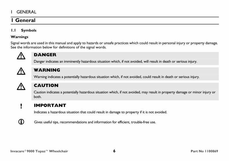
Signal words are used in this manual and apply to hazards or unsafe practices which could result in personal injury or property damage. See the information below for definitions of the signal words.
� DANGERDanger indicates an imminently hazardous situation which, if not avoided, will result in death or serious injury.
� WARNINGWarning indicates a potentially hazardous situation which, if not avoided, could result in death or serious injury.
� CAUTIONCaution indicates a potentially hazardous situation which, if not avoided, may result in property damage or minor injury or both.
! IMPORTANTIndicates a hazardous situation that could result in damage to property if it is not avoided.
Gives useful tips, recommendations and information for efficient, trouble-free use.
Invacare®9000 Topaz™Wheelchair 6 Part No 1100869
1 GENERAL1.2 Limited WarrantyPLEASE NOTE: THE WARRANTY BELOW HAS BEEN DRAFTED TO COMPLY WITH FEDERAL LAW APPLICABLE TO PRODUCTS MANUFACTURED AFTER JULY 4, 1975.This warranty is extended only to the original purchaser who purchases this product when new and unused from Invacare or a dealer. This warranty is not extended to any other person or entity and is not transferable or assignable to any subsequent purchaser or owner. Coverage under this warranty will end upon any such subsequent sale or other transfer of title to any other person.This warranty gives you specific legal rights and you may also have other legal rights which vary from state to state.Invacare warrants the side frames and cross members of this product when purchased new and unused to be free from defects in materials and workmanship for a period of three years from the date of purchase from Invacare or a dealer, with a copy of the seller’s invoice required for coverage under this warranty. Invacare warrants the upholstered materials (seat, back and armrests of the arm assembly) and remaining components of this product when purchased new and unused to be free from defects in materials and workmanship for a period of thirteen months from date of purchase from Invacare or a dealer, with a copy of the seller’s invoice required for coverage under this warranty. If within such warranty periods any such product shall be proven to be defective, such product shall be repaired or replaced, at Invacare’s option. This warranty does not include any labor or shipping charges incurred in replacement part installation or repair of any such product. Invacare’s sole obligation and your exclusive remedy under this warranty shall be limited to such repair and/or replacement.For warranty service, please contact the dealer from whom you purchased your Invacare product. In the event you do not receive satisfactory warranty service, please write directly to Invacare at the address at the bottom of this page. Provide dealer’s name, address, the product model number, date of purchase, indicate nature of the defect and, if the product is serialized, indicate the serial number. Do not return products to our factory without our prior consent.LIMITATIONS AND EXCLUSIONS: THE FOREGOING WARRANTY SHALL NOT APPLY TO SERIAL NUMBERED PRODUCTS IF THE SERIAL NUMBER HAS BEEN REMOVED OR DEFACED, PRODUCTS SUBJECTED TO NEGLIGENCE, ACCIDENT, IMPROPER OPERATION, MAINTENANCE OR STORAGE, PRODUCTS MODIFIED WITHOUT INVACARE’S EXPRESS WRITTEN CONSENT INCLUDING, BUT NOT LIMITED TO, MODIFICATION THROUGH THE USE OF UNAUTHORIZED PARTS OR ATTACHMENTS; PRODUCTS DAMAGED BY REASON OF REPAIRS MADE TO ANY COMPONENT WITHOUT THE SPECIFIC CONSENT OF INVACARE, OR TO A PRODUCT DAMAGED BY CIRCUMSTANCES BEYOND INVACARE’S CONTROL, AND SUCH EVALUATION WILL BE SOLELY DETERMINED BY INVACARE. THE WARRANTY SHALL NOT APPLY TO NORMAL WEAR AND TEAR OR FAILURE TO ADHERE TO THE PRODUCT INSTRUCTIONS.THE FOREGOING EXPRESS WARRANTY IS EXCLUSIVE AND IN LIEU OF ANY OTHER WARRANTIES WHATSOEVER, WHETHER EXPRESS OR IMPLIED, INCLUDING THE IMPLIED WARRANTIES OF MERCHANTABILITY AND FITNESS FOR A PARTICULAR PURPOSE, AND THE SOLE REMEDY FOR VIOLATIONS OF ANY WARRANTY WHATSOEVER, SHALL BE LIMITED TO REPAIR OR REPLACEMENT OF THE DEFECTIVE PRODUCT PURSUANT TO THE TERMS CONTAINED HEREIN. THE APPLICATION OF ANY IMPLIED WARRANTY WHATSOEVER SHALL NOT EXTEND BEYOND THE DURATION OF THE EXPRESS WARRANTY PROVIDED HEREIN. INVACARE SHALL NOT BE LIABLE FOR ANY CONSEQUENTIAL OR INCIDENTAL DAMAGES WHATSOEVER.SOME STATES DO NOT ALLOW THE EXCLUSION OR LIMITATION OF INCIDENTAL OR CONSEQUENTIAL DAMAGE, OR LIMITATION OF HOW LONG AN IMPLIED WARRANTY LASTS, SO THE ABOVE EXCLUSION AND LIMITATION MAY NOT BE APPLICABLE.THIS WARRANTY SHALL BE EXTENDED TO COMPLY WITH STATE/PROVINCIAL LAWS AND REQUIREMENTS.
Part No 1100869 7 Invacare®9000 Topaz™Wheelchair

2 OVERVIEW
2 Overview
2.1 Label Location
WARNING
Do not remove label. Replace if dam aged P/N 1134890 REV A 08/05
DO NOT place hands or fingers on underside of seat rails when opening or closing wheelchair. Ensure that seat is fully open BEFORE sitting in wheelchair. Otherwise, serious injury may occur.
WARNINGDO NOT OPERATE WITHOUT
THE ANTI-TIP TUBESINSTALLED.REV. 5/98 P/N 60106X144
1079203 located on seat rail next to the middle H-block.
p/n
1183
421
Rev
ABefore using this product, read and understand the User Manual. The user manual provides proper operation and safe practices.Documentation can be obtained at: • www.invacare.com • ph (440) 329-6000 • One Invacare Way, Elyria OH 44035-2125
Invacare®9000 Topaz™Wheelchair 8 Part No 1100869

2 OVERVIEW2.2 Component Identification
Seat Upholstery
Back Upholstery
Rear Wheel
Rear Wheel Axle
Wheel Lock
Wheelchair Frame
Front CasterHandrim
Part No 1100869 9 Invacare®9000 Topaz™Wheelchair

2 OVERVIEW2.3 Specifications
9000 TOPAZSEAT WIDTH 20, 22, 24, 26, 28 or 30 inches HANDRIMS 700 lb version (Chrome steel or aluminum)
1000 lb version (Aluminum)
OVERALL WIDTH Seat width plus 8 1/2 inches WHEEL LOCKS Toggle lock - push or pull
SEAT DEPTH 18, 20 inches CASTER SIZE 700 lb version (6 x 2 inch Urethane, 8 x 13/4 inch Semi-pneumatic);1000 lb version (8 x 2 inch)
OVERALL DEPTH(WITH RIGGINGS)
49 inches UPHOLSTERY Black nylon, black vinyl, or blue vinyl
SEAT-TO-FLOOR 191/2, 171/2, 151/2 inches FRAME COLORS Silver Vein or Wet Black
BACK STYLE Adjustable in 1 inch increments WEIGHT* 700 lb version (82 lbs);1000 lb version (86 lbs)
BACK HEIGHT 16, 17 and 18 inches SHIPPING WEIGHT**
700 lb version (117 lbs):1000 lb version (121 lbs)(Approx.)
ARM STYLES Conventional, desk/full length fixed/adjustable height
WEIGHT LIMIT 700 lbs1000 lbs with heavy duty frame
FRONT RIGGINGS Swingaway footrests and elevating legrests
* Chair only without footrest (30-inches wide X 20-inches deep)
**Chair with footrest (30-inches wide X 20-inches deep)REAR AXLE Permanent
REAR WHEELS 700 lb version (24 inch solid or 20 inch pneumatic with flat-free insert);1000 lb version (24 inch solid)
Invacare®9000 Topaz™Wheelchair 10 Part No 1100869
3 SAFETY
3 Safety
The safety section contains important information for the safe operation and use of this product.
3.1 General Guidelines
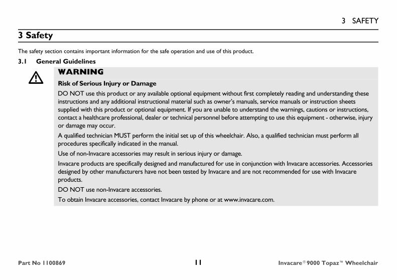
� WARNINGRisk of Serious Injury or Damage
DO NOT use this product or any available optional equipment without first completely reading and understanding these instructions and any additional instructional material such as owner’s manuals, service manuals or instruction sheets supplied with this product or optional equipment. If you are unable to understand the warnings, cautions or instructions, contact a healthcare professional, dealer or technical personnel before attempting to use this equipment - otherwise, injury or damage may occur.
A qualified technician MUST perform the initial set up of this wheelchair. Also, a qualified technician must perform all procedures specifically indicated in the manual.
Use of non-Invacare accessories may result in serious injury or damage.
Invacare products are specifically designed and manufactured for use in conjunction with Invacare accessories. Accessories designed by other manufacturers have not been tested by Invacare and are not recommended for use with Invacare products.
DO NOT use non-Invacare accessories.
To obtain Invacare accessories, contact Invacare by phone or at www.invacare.com.
Part No 1100869 11 Invacare®9000 Topaz™Wheelchair

3 SAFETY
3.2 Intended UseThe intended use for the manual (mechanical) wheelchair is to provide mobility to persons who may be restricted to a sitting position. The manual wheelchair is intended for ongoing daily use. The models offer a wide range of customization which allows for a better fit for the end user resulting in comfort, lightweight, easier propelling, transferring, and smooth ride. The manual wheelchair is intended for indoor and outdoor use on firm surfaces free of climbing obstacles. All other uses are prohibited.
� DANGERRisk of Death, Serious Injury or DamageUse of incorrect or improper replacement (service) parts may cause death, serious injury, or damage.
Replacement parts MUST match original Invacare parts.
ALWAYS provide the wheelchair serial number to assist in ordering the correct replacement parts.
� DANGERRisk of Death, Serious Injury, or DamageLighted cigarettes dropped onto an upholstered seating system can cause a fire resulting in death, serious injury, or damage.
Wheelchair occupants are at particular risk of death or serious injury from these fires and resulting fumes because they may not have the ability to move away from the wheelchair.
DO NOT smoke while using this wheelchair.
! NOTICETHE INFORMATION CONTAINED IN THIS DOCUMENT IS SUBJECT TO CHANGE WITHOUT NOTICE.Check all parts for shipping damage and test before using. In case of damage, DO NOT use. Contact Invacare/Carrier for further instruction.
Invacare®9000 Topaz™Wheelchair 12 Part No 1100869
3 SAFETY3.3 Wear and Tear Items
3.4 Repair and Service Information
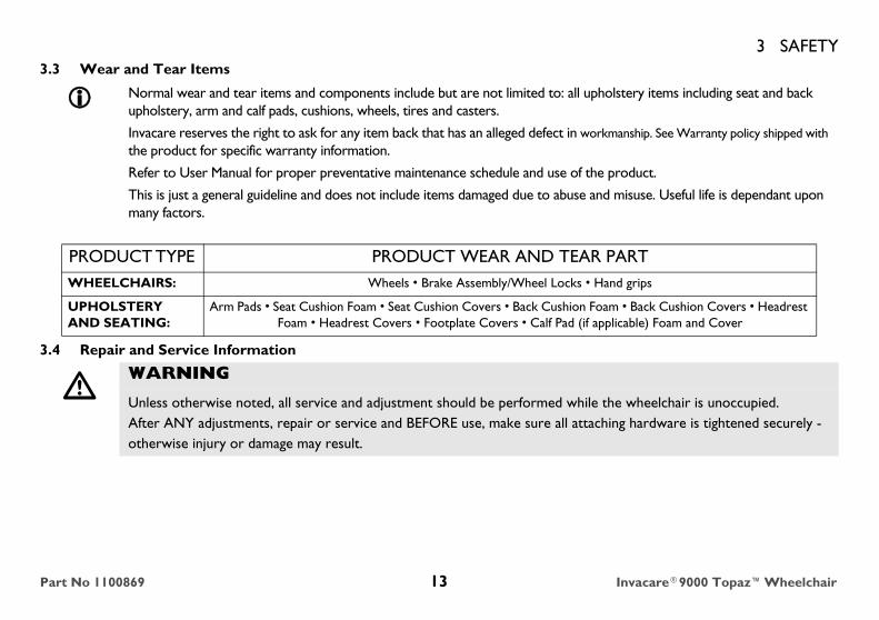
Normal wear and tear items and components include but are not limited to: all upholstery items including seat and back upholstery, arm and calf pads, cushions, wheels, tires and casters.
Invacare reserves the right to ask for any item back that has an alleged defect in workmanship. See Warranty policy shipped with the product for specific warranty information.
Refer to User Manual for proper preventative maintenance schedule and use of the product.
This is just a general guideline and does not include items damaged due to abuse and misuse. Useful life is dependant upon many factors.
PRODUCT TYPE PRODUCT WEAR AND TEAR PARTWHEELCHAIRS: Wheels • Brake Assembly/Wheel Locks • Hand grips
UPHOLSTERY AND SEATING:
Arm Pads • Seat Cushion Foam • Seat Cushion Covers • Back Cushion Foam • Back Cushion Covers • Headrest Foam • Headrest Covers • Footplate Covers • Calf Pad (if applicable) Foam and Cover
� WARNING
Unless otherwise noted, all service and adjustment should be performed while the wheelchair is unoccupied.After ANY adjustments, repair or service and BEFORE use, make sure all attaching hardware is tightened securely - otherwise injury or damage may result.
Part No 1100869 13 Invacare®9000 Topaz™Wheelchair
3 SAFETY3.5 Operating Information
General Warnings
� WARNINGTo determine and establish your particular safety limits, practice bending, reaching and transferring activities in several combinations in the presence of a qualified healthcare professional before attempting active use of the wheelchair.
Avoid storing or using the wheelchair near open flame or combustible products. Serious injury or damage to property may result.
DO NOT stand on the frame of the wheelchair.
DO NOT use the footplate as a platform. When getting in or out of the wheelchair, make sure that the footplates are in the upward position.
ALWAYS use the handrims for self-propulsion. Inasmuch as the HANDRIMS are an option on this wheelchair (you may order with or without the handrims), Invacare strongly recommends ordering the handrims as an additional safeguard for the wheelchair user.
Invacare recommends that a non-folding device be installed to keep the wheelchair from being folded when left unoccupied in a public place.
DO NOT operate on roads, streets or highways.
DO NOT allow children to play on or operate the wheelchair.
DO NOT operate on soft surfaces such as sand, grass, or gravel.
Invacare®9000 Topaz™Wheelchair 14 Part No 1100869

3 SAFETYAnti-Tippers
Hand Grips
� WARNING
Anti-tippers are specific to the different rear wheels and/or seat-to-floor heights. Refer to the chart in Installing Anti-Tippers on page 51 for correct usage and adjustment. If these requirements cannot be achieved, DO NOT use the wheelchair. Contact an Invacare dealer or qualified technician. Any changes to the seat-to-floor angle or seat-to-floor height may require different anti-tippers. The correct anti-tippers MUST be ordered to maintain a 3.81 x 5.08 cm (1½ to 2 in) ground clearance.Inasmuch as the anti-tippers are an option on this wheelchair (you may order with or without the anti-tippers), Invacare strongly recommends ordering the anti-tippers as an additional safeguard for the wheelchair user.Invacare strongly recommends that anti-tippers be used at all times.The manual wheelchair is intended for indoor and outdoor use on firm surfaces. When outdoors on wet, soft ground or on gravel surfaces, anti-tippers may not provide the same level of protection against tip over. DO NOT operate on soft surfaces such as sand, grass or gravel.
� WARNINGALWAYS check hand grips for looseness before using the wheelchair. If loose and/or worn, replace IMMEDIATELY.
When cleaning rear cane or hand grip areas use only a clean towel lightly dampened with cool water. Verify that grips are dry prior to use. Use of soap or ammonia based cleaning solutions will result in the hand grips sliding off the cane assembly. Failure to observe this warning may result in injury to the user or bystanders.
If the wheelchair is exposed to extreme temperature (above 100°F or below 32°F), high humidity and/or becomes wet, prior to use, ensure that the handgrips DO NOT twist on the handle. Otherwise, damage or injury may occur.
Part No 1100869 15 Invacare®9000 Topaz™Wheelchair
3 SAFETYWheel Locks
Seat Positioning Straps
� WARNINGDO NOT attempt to stop a moving wheelchair with wheel locks. Wheel locks are not brakes.
If the wheelchair is equipped with push to lock wheel locks, elevating legrests, and wheel lock extension handles, the wheel lock extension handles MUST be removed before swinging the elevating legrests to the side, otherwise injury or damage may result. Interference between the top of the elevating legrest and the wheel lock extension handle causes the wheel lock to disengage.
Engaging the wheel locks may not prevent the wheelchair from moving on all floor surfaces including those that may be wet or slick. ALWAYS exercise caution when transferring into or out of the wheelchair.
� WARNINGALWAYS wear your seat positioning strap. Inasmuch as the seat positioning strap is an option on this wheelchair (you may order with or without the seat positioning strap), Invacare strongly recommends ordering the seat positioning strap as an additional safeguard for the wheelchair user. The seat positioning strap is a positioning strap only. It is not designed for use as a safety device withstanding high stress loads such as auto or aircraft safety belts. If signs of wear appear, strap MUST be replaced IMMEDIATELY.
With regards to seat/chest positioning straps - it is the obligation of the DME dealer, therapists and other healthcare professionals to determine if a seat/chest positioning strap is required to ensure the safe operation of this equipment by the user. Serious injury can occur in the event of a fall from a wheelchair.
Invacare®9000 Topaz™Wheelchair 16 Part No 1100869
3 SAFETYWheelchair Tie Down Restraints
Tire Pressure
Lifting
Weight Limitation
� WARNINGInvacare recommends that wheelchair users not be transported in vehicles of any kind while in wheelchairs. As of this date, the Department of Transportation has not approved any tie-down systems for transportation of a user while in a wheelchair, in a moving vehicle of any type.
It is Invacare’s position that users of wheelchairs should be transferred into appropriate seating in vehicles for transportation and use be made of the restraints made available by the auto industry. Invacare cannot and does not recommend any wheelchair transportation systems.
� WARNINGDO NOT use your wheelchair unless it has the proper tire pressure (p.s.i.). DO NOT overinflate the tires. Failure to follow these suggestions may cause the tire to explode and cause bodily harm. The recommended tire pressure is on the sidewall of the tire.
� WARNINGDO NOT attempt to lift the wheelchair by any removable (detachable) parts. Lifting by means of any removable (detachable) parts of the wheelchair may result in injury to the user or damage to the wheelchair.
� WARNINGWeight limitation is 700 lbs. Weight limitation with heavy duty frame is 1,000 lbs.
Part No 1100869 17 Invacare®9000 Topaz™Wheelchair
3 SAFETYWeight Training
Storage
� WARNINGInvacare does not recommend the use of its wheelchairs as a weight training apparatus. Invacare wheelchairs have not been designed or tested as a seat for any kind of weight training. If occupant uses said wheelchair as a weight training apparatus, Invacare shall not be liable for bodily injury or damage to the wheelchair and the warranty is void.
� WARNINGRisk of Serious Injury or Damage
Storing or using the wheelchair near open flame or combustible products can result is serious injury or damage.
Avoid storing or using the wheelchair near open flame or combustible products.
Storing the wheelchair in a damp area or when wet may cause rust or corrosion of wheelchair parts resulting in injury or damage.
DO NOT use the wheelchair in a shower, pool or other body of water.
DO NOT store the wheelchair in a damp or humid area.
Avoid extreme weather such as rain or snow when possible.
Avoid excessive moisture or humidity.
If exposed to water, dry the wheelchair as soon as possible.
Invacare®9000 Topaz™Wheelchair 18 Part No 1100869

3 SAFETYStability
� WARNINGThe back height, front caster position, caster size, seat-to-floor angle, position of the rear wheels, correct anti-tipper as well as the end user's disability or end user's physical condition and capabilities directly relate to the stability of the wheelchair. Any change to one or any combination of the seven may cause the wheelchair to decrease in stability. These adjustments MUST be performed by a qualified technician.
Seat-to-floor heights have specific positions depending on rear wheel size, rear wheel position, front caster position and seat-to-floor angle. These adjustments must be performed by a qualified technician.
BAC
K H
EIG
HT
SEA
T-T
O-F
LOO
RA
NG
LE
CA
STER
SIZ
E
CA
STER
PO
SIT
ION
WH
EEL
POSI
TIO
N
USE
R C
ON
DIT
ION
AN
TI-T
IPPE
RS
BACK HEIGHT • X X X X N/A N/ACASTER POSITION X N/A X • X N/A XCASTER SIZE X N/A • X X N/A XSEAT-TO-FLOOR ANGLE N/A • N/A N/A N/A N/A N/AWHEEL POSITION X N/A X X • N/A XUSER CONDITION X X X X X • N/AANTI-TIPPERS N/A N/A N/A N/A N/A N/A •
When changes to the left hand column occur, follow across the chart and refer to the X procedure to maintain the proper stability, safety and handling of the wheelchair.
Part No 1100869 19 Invacare®9000 Topaz™Wheelchair

3 SAFETYRamps, Slopes, Inclines, and Obstacles
Information for Healthcare Professionals/Assistants
Wheelchair User
� WARNINGDO NOT traverse, climb or go down ramps or slopes greater than 4°.
DO NOT attempt to move up or down an incline with a water, ice or oil film.
DO NOT attempt to ride over curbs or obstacles. Doing so may cause your wheelchair to tip over and cause bodily harm to you or damage to the wheelchair
NEVER leave an unoccupied wheelchair on an incline.
DO NOT attempt to stop the wheelchair while on a sloped surface.
� WARNINGWhen assistance to the wheelchair user is required, remember to use good body mechanics. Keep your back straight and bend your knees whenever tipping the wheelchair or traversing curbs, or other impediments.
When learning a new assistance technique, have an experienced assistant help you before attempting it alone.
� WARNINGAs a manufacturer of wheelchairs, Invacare endeavors to supply a wide variety of wheelchairs to meet many needs of the end user. However, final selection of the type of wheelchair to be used by an individual rests solely with the user and his/her healthcare professional capable of making such a selection.
The intended use for this wheelchair is for the bariatric user.
Invacare®9000 Topaz™Wheelchair 20 Part No 1100869

3 SAFETY3.6 Safety/Handling of WheelchairsSafety and handling of the wheelchair requires the close attention of the wheelchair user as well as the assistant. This manual points out the most common procedures and techniques involved in the safe operation and maintenance of the wheelchair. It is important to practice and master these safe techniques until you are comfortable in maneuvering around the frequently encountered architectural barriers.Use this information only as a basic guide. The techniques that are discussed on the following pages have been used successfully by many.Individual wheelchair users often develop skills to deal with daily living activities that may differ from those described in this manual. Invacare recognizes and encourages each individual to try what works best for him/her in overcoming architectural obstacles that they may encounter. However, all WARNINGS and CAUTIONS given in this manual, MUST be followed. Techniques in this manual are a starting point for the new wheelchair user and assistant with safety as the most important consideration for all.
Stability and Balance
To assure stability and proper operation of your wheelchair, you must at all times wear your seat positioning strap and maintain proper balance. Your wheelchair has been designed to remain upright and stable during normal daily activities as long as you do not move beyond the center of gravity.Virtually all activities which involve movement in the wheelchair have an effect on the center of gravity. Invacare recommends using seat/chest positioning straps for additional safety while involved in activities that shift your weight.DO NOT lean forward out of the wheelchair any further than the length of the armrests. Make sure the casters are pointing in the forward position whenever you lean forward. This can be achieved by advancing the wheelchair and then reversing it in a straight line.Many activities require the wheelchair user to reach, bend and transfer in and out of the wheelchair. These movements will cause a change to normal balance, center of gravity, and weight distribution of the wheelchair. To determine and establish your particular safety limits, practice bending, reaching and transferring activities in several combinations in the presence of a qualified healthcare professional before attempting active use of the wheelchair.Proper positioning is essential for your safety. When reaching, leaning, bending forward, it is important to use the front casters as a tool to maintain stability and balance.
� WARNINGBe aware that carrying heavy objects on your lap while occupying the wheelchair may adversely affect the stability of the wheelchair, resulting in serious bodily injury to the user, damage to the wheelchair and surrounding property.
This wheelchair has been designed to accommodate one individual. If more than one individual occupies the wheelchair this may adversely affect the stability of the wheelchair, resulting in serious bodily injury to the user and passenger and damage to the wheelchair and surrounding property.
Part No 1100869 21 Invacare®9000 Topaz™Wheelchair

3 SAFETYReaching, Leaning and Bending
Forward
Position the front casters so that they are extended as far forward as possible and engage wheel locks.
Backward
Position wheelchair as close as possible to the desired object. Point front casters forward to create the longest possible wheelbase. Reach back only as far as your arm will extend without changing your sitting position.
FIGURE 1 Reaching, Leaning and Bending
Coping With Everyday ObstaclesCoping with the irritation of everyday obstacles can be alleviated somewhat by learning how to manage your wheelchair. Keep in mind your center of gravity to maintain stability and balance.
� WARNINGDO NOT shift your weight or sitting position toward direction you are reaching as the wheelchair may tip over.
DO NOT attempt to reach objects if you have pick them up from the floor by reaching down between your knees.
DO NOT lean over the top of the back upholstery to reach objects behind you, as this may cause the wheelchair to tip over.
Invacare®9000 Topaz™Wheelchair 22 Part No 1100869
3 SAFETYTipping
Stairways
Follow this procedure for moving the wheelchair between floors when an elevator is NOT available:
Moving Up Stairs1. Remove the occupant from the wheelchair.
2. If necessary, rotate the anti-tippers so the wheels are facing up.
3. One assistant (positioned behind the wheelchair), securely grasps a non-removable (non-detachable) part of the wheelchair for leverage and tilts the wheelchair back to the balance point.
4. After the wheelchair has been tilted back to the balance point, the assistant behind the wheelchair backs the wheelchair up against the first step.
5. The second assistant (positioned in the front of the wheelchair), with a firm hold on a non-detachable part of the framework, lifts the wheelchair up and on to the next stair above and steadies the wheelchair as the assistant behind the wheelchair places one foot on the next stair above and repeats process.
6. The wheelchair should not be lowered until the last stair has been negotiated and the wheelchair has been rolled away from the stairway.
7. If necessary, rotate the anti-tippers so the wheels are facing down.
� WARNINGDO NOT tip the wheelchair when occupied to traverse curbs or other such obstructions. Always use curb cuts. Otherwise, injury or damage may result.
� WARNINGExtreme caution is advised when it is necessary to move an unoccupied wheelchair up or down the stairs. Invacare recommends using two assistants and making thorough preparations. Make sure to use only secure, non-detachable parts for hand-hold supports.
DO NOT attempt to lift the wheelchair by any removable (detachable) parts. Lifting by means of any removable (detachable) parts of a wheelchair may result in injury to the user or damage to the wheelchair.
Part No 1100869 23 Invacare®9000 Topaz™Wheelchair
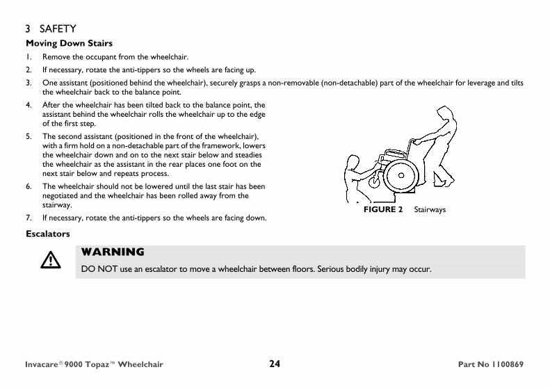
3 SAFETYMoving Down Stairs1. Remove the occupant from the wheelchair.
2. If necessary, rotate the anti-tippers so the wheels are facing up.
3. One assistant (positioned behind the wheelchair), securely grasps a non-removable (non-detachable) part of the wheelchair for leverage and tilts the wheelchair back to the balance point.
4. After the wheelchair has been tilted back to the balance point, the assistant behind the wheelchair rolls the wheelchair up to the edge of the first step.
5. The second assistant (positioned in the front of the wheelchair), with a firm hold on a non-detachable part of the framework, lowers the wheelchair down and on to the next stair below and steadies the wheelchair as the assistant in the rear places one foot on the next stair below and repeats process.
6. The wheelchair should not be lowered until the last stair has been negotiated and the wheelchair has been rolled away from the stairway.
7. If necessary, rotate the anti-tippers so the wheels are facing down.FIGURE 2 Stairways
Escalators
� WARNINGDO NOT use an escalator to move a wheelchair between floors. Serious bodily injury may occur.
Invacare®9000 Topaz™Wheelchair 24 Part No 1100869
3 SAFETYTransferring To and From Other Seats
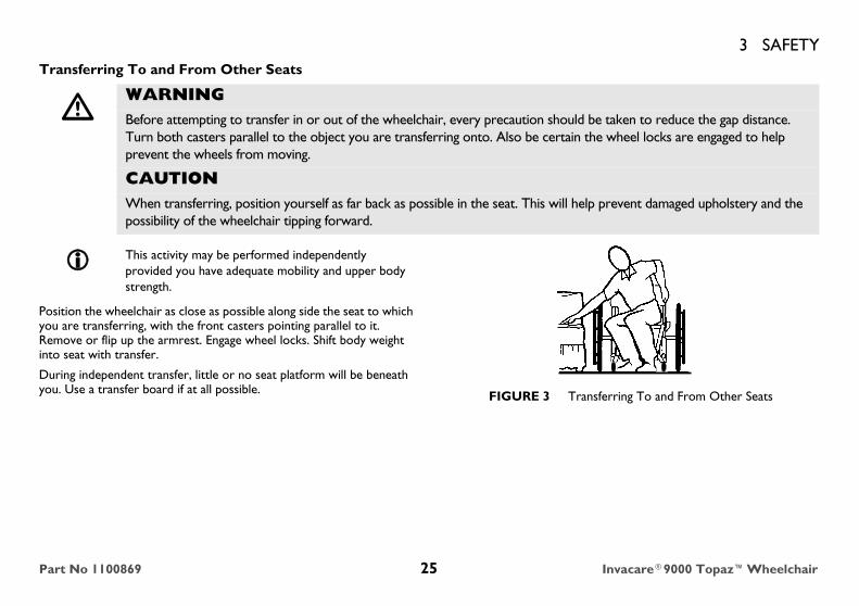
Position the wheelchair as close as possible along side the seat to which you are transferring, with the front casters pointing parallel to it. Remove or flip up the armrest. Engage wheel locks. Shift body weight into seat with transfer.
During independent transfer, little or no seat platform will be beneath you. Use a transfer board if at all possible. FIGURE 3 Transferring To and From Other Seats
� WARNINGBefore attempting to transfer in or out of the wheelchair, every precaution should be taken to reduce the gap distance. Turn both casters parallel to the object you are transferring onto. Also be certain the wheel locks are engaged to help prevent the wheels from moving.
CAUTIONWhen transferring, position yourself as far back as possible in the seat. This will help prevent damaged upholstery and the possibility of the wheelchair tipping forward.
This activity may be performed independently provided you have adequate mobility and upper body strength.
Part No 1100869 25 Invacare®9000 Topaz™Wheelchair
3 SAFETYUnfolding and Folding Wheelchair
Unfolding
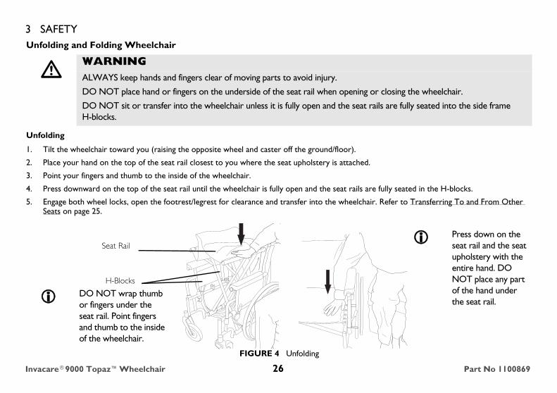
1. Tilt the wheelchair toward you (raising the opposite wheel and caster off the ground/floor).
2. Place your hand on the top of the seat rail closest to you where the seat upholstery is attached.
3. Point your fingers and thumb to the inside of the wheelchair.
4. Press downward on the top of the seat rail until the wheelchair is fully open and the seat rails are fully seated in the H-blocks.
5. Engage both wheel locks, open the footrest/legrest for clearance and transfer into the wheelchair. Refer to Transferring To and From Other Seats on page 25.
FIGURE 4 Unfolding
� WARNINGALWAYS keep hands and fingers clear of moving parts to avoid injury.
DO NOT place hand or fingers on the underside of the seat rail when opening or closing the wheelchair.
DO NOT sit or transfer into the wheelchair unless it is fully open and the seat rails are fully seated into the side frame H-blocks.
Seat Rail
H-Blocks
DO NOT wrap thumb or fingers under the seat rail. Point fingers and thumb to the inside of the wheelchair.
Press down on the seat rail and the seat upholstery with the entire hand. DO NOT place any part of the hand under the seat rail.
Invacare®9000 Topaz™Wheelchair 26 Part No 1100869
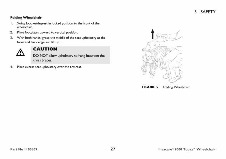
3 SAFETYFolding Wheelchair
1. Swing footrest/legrest in locked position to the front of the wheelchair.
2. Pivot footplates upward to vertical position.
3. With both hands, grasp the middle of the seat upholstery at the front and back edge and lift up.
4. Place excess seat upholstery over the armrest.
FIGURE 5 Folding Wheelchair
� CAUTIONDO NOT allow upholstery to hang between the cross braces.
Part No 1100869 27 Invacare®9000 Topaz™Wheelchair
4 SAFETY INSPECTION/TROUBLESHOOTING.
4 Safety Inspection/Troubleshooting.
4.1 Safety Inspection ChecklistsInitial adjustments should be made to suit your personal body structure and preference. Thereafter follow these maintenance procedures:
Inspect/Adjust Initially❑ Ensure that the wheelchair rolls straight (no excessive drag or pull to one side).
❑ Inspect for loose or missing hardware on frame and crossbraces.
❑ Inspect for bent frame or crossbraces.
❑ Check that the wheel locks do not interfere with tires when rolling.
❑ Check that the wheel lock pivot points are free of wear and looseness.
❑ Check that the wheel locks are easy to engage.
❑ Ensure that the wheel locks prevent the wheelchair from moving when engaged.
❑ Inspect seat and back for rips and sagging.
❑ Inspect seat for damaged or missing warning label.
❑ Inspect seat and back for loose or broken hardware.
❑ Inspect back cane hand grips for wear/looseness/deterioration.
❑ Inspect seat positioning strap for any signs of wear. Ensure buckle latches. Verify hardware that attaches strap to frame is secure and undamaged. Replace if necessary.
❑ Inspect tires for flat spots and wear.
Every six months or as necessary, take your wheelchair to a qualified technician for a thorough inspection and servicing. Regular cleaning will reveal loose or worn parts and enhance the smooth operation of your wheelchair. To operate properly and safely, your wheelchair MUST be cared for just like any other vehicle. Routine maintenance will extend the life and efficiency of your wheelchair.
Invacare®9000 Topaz™Wheelchair 28 Part No 1100869

4 SAFETY INSPECTION/TROUBLESHOOTING.
❑ Check that there is no excessive side movement or binding in the rear wheels when lifted and spun.
❑ Inspect rear wheels for cracked, broken or loose spokes.
❑ Ensure all spokes are uniformly tight.
❑ Inspect handrims for signs of rough edges or peeling.
❑ Inspect axle assembly for proper tension by spinning caster. Caster should come to a gradual stop.
❑ Adjust front casters/forks bearing system if wheel wobbles noticeably or binds to a stop.
❑ Ensure wheel bearings are clean and free of moisture.
❑ Inspect casters for cracks and wear.
❑ Clean upholstery and armrests.
❑ Check that all labels are present and legible. Replace if necessary.
Inspect/Adjust Weekly❑ Inspect tires for flat spots and wear.
❑ Inspect rear wheels for cracked, broken or loose spokes.
❑ Ensure all spokes are uniformly tight.
❑ Inspect axle assembly for proper tension by spinning caster. Caster should come to a gradual stop.
� CAUTIONAs with any vehicle, check the wheels and tires periodically for cracks and wear. Replace if damaged.
� CAUTIONDamage from Bleach
Clean upholstery with mild soap and water or spray disinfectant using a sponge. DO NOT use bleach or wash in a washing machine.
Part No 1100869 29 Invacare®9000 Topaz™Wheelchair

4 SAFETY INSPECTION/TROUBLESHOOTING.Inspect/Adjust Monthly❑ Check that the wheel locks do not interfere with tires when rolling.
❑ Check that the wheel lock pivot points are free of wear and looseness.
❑ Inspect seat and back for loose or broken hardware.
❑ Inspect cane hand grips for wear/looseness/deterioration.
❑ Inspect seat positioning strap for any signs of wear. Ensure buckle latches. Verify hardware that attaches strap to frame is secure and undamaged. Replace if necessary.
❑ Adjust front casters/forks bearing system if wheel wobbles noticeably or binds to a stop.
❑ Ensure wheel bearings are clean and free of moisture.
Inspect/Adjust Periodically❑ Ensure that the wheelchair rolls straight (no excessive drag or pull to one side).
❑ Inspect frame and crossbraces for loose or missing hardware.
❑ Inspect for bent frame or crossbraces.
❑ Check that wheel locks are easy to engage.
❑ Ensure that casters are free of debris.
❑ Inspect seat and backs for rips and sagging.
❑ Inspect seat for damaged or missing warning label.
❑ Check that there is no excessive side movement or binding in the rear wheels when lifted and spun.
❑ Clean upholstery and armrests.
❑ Check that all labels are present and legible. Replace if necessary.
Invacare®9000 Topaz™Wheelchair 30 Part No 1100869
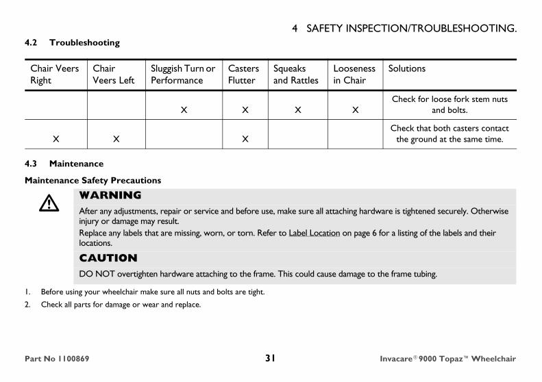
4 SAFETY INSPECTION/TROUBLESHOOTING.4.2 Troubleshooting
4.3 Maintenance
Maintenance Safety Precautions
1. Before using your wheelchair make sure all nuts and bolts are tight.
2. Check all parts for damage or wear and replace.
Chair Veers Right
Chair Veers Left
Sluggish Turn or Performance
Casters Flutter
Squeaks and Rattles
Loosenessin Chair
Solutions
X X X XCheck for loose fork stem nuts
and bolts.
X X XCheck that both casters contact
the ground at the same time.
� WARNINGAfter any adjustments, repair or service and before use, make sure all attaching hardware is tightened securely. Otherwise injury or damage may result.Replace any labels that are missing, worn, or torn. Refer to Label Location on page 6 for a listing of the labels and their locations.
CAUTIONDO NOT overtighten hardware attaching to the frame. This could cause damage to the frame tubing.
Part No 1100869 31 Invacare®9000 Topaz™Wheelchair

4 SAFETY INSPECTION/TROUBLESHOOTING.3. Check all parts for proper adjustment.
4. The rear wheels, casters and tires should be checked periodically for cracks and wear, and should be replaced by a qualified technician if damaged.
5. Periodically adjust wheel locks in correlation to tire wear. Refer to Using/Adjusting Wheel Locks on page 53.
6. Periodically check handrims to ensure they are securely attached to the rear wheels.
7. Periodically check caster wheel bearings to make sure they are clean and free from moisture. Use a Teflon® lubricant if necessary.
8. Check upholstery for sagging, rips or tears.
9. Clean upholstery with mild soap and water.
10. Replace any labels that are missing, worn, or torn. Refer to Label Location on page 8 for a listing of labels and their locations.
11. Hand grips should be checked monthly for wear/looseness/deterioration. Clean if desired. Replace if looseness or deterioration is found.
� CAUTIONAs with any vehicle, check the wheels and tires periodically for cracks and wear. Replace if damaged. Replace as recommended, refer to Replacing/Repairing Rear Wheel Tire/Tube on page 33 and Replacing/Repairing Caster Tire/Tube on page 33.
Tire wear is excessive if:
Pneumatic Tires - there is missing tread or the tires are bald.
Urethane Tires - there are cuts, surface defects or the tires are loose on the rims.
Rubber Tires - 30% or more of the tire has worn away.
Invacare recommends that tires and casters be replaced every five years.
� WARNINGWhen cleaning rear cane or hand grip areas use only a clean towel lightly dampened with cool water. Verify that grips are dry prior to use. Use of soap or ammonia based cleaning solutions will result in the hand grips sliding off the cane assembly. Failure to observe this warning may result in injury to the user or bystanders.
Invacare®9000 Topaz™Wheelchair 32 Part No 1100869
4 SAFETY INSPECTION/TROUBLESHOOTING.Replacing/Repairing Rear Wheel Tire/Tube
Replacing/Repairing Caster Tire/Tube
4.4 Cleaning Instructions
Cleaning Upholstery, Cloth, Vinyl
If necessary, for cleaning cushion upholstery, refer to the seating user manual shipped with the product.
� WARNINGReplacement of solid urethane tires is not recommended. If the solid urethane tire needs repaired, Invacare recommends replacing the complete wheel assembly.
Replacement of rear wheel tube must be performed by a qualified technician.
� WARNINGReplacement of solid urethane or semi-pneumatic tires is not recommended. If the solid urethane or semi-pneumatic tires need replaced, Invacare recommends replacing complete caster assembly.
For pneumatic tires, replacement of the tire or tube must be performed by a qualified technician.
Regular cleaning will reveal loose or worn parts and enhance the smooth operation of your wheelchair. To operate properly and safely, your wheelchair must be cared for just like any other vehicle.
For upholstery that is severely stained or surface finish that is badly damaged, contact the seating system manufacturer for further information.
� CAUTIONDamage from Bleach
Clean upholstery with mild soap and water or spray disinfectant using a sponge. DO NOT use bleach or wash in a washing machine.
Part No 1100869 33 Invacare®9000 Topaz™Wheelchair

4 SAFETY INSPECTION/TROUBLESHOOTING.Cleaning Metal SurfacesHot water and a mild detergent on soft cloth should be used for cleaning metal surfaces. Wipe down with damp cloth. Dry surface by wiping down with dry cloth.Car polish and soft wax can be used to remove abrasions and restore gloss (Follow manufacturer’s instructions).
Cleaning Plastic SurfacesPlastic surfaces should be cleaned with soft cloth, mild detergent, and hot water. Rinse surface with clean water. Dry surface with soft cloth. Solvents or kitchen cleaners must not be used on plastic surfaces.
Cleaning I.V. Rod/O2 Holder
1. Remove the user, any I.V. medication and the O2 cylinder from the wheelchair.
2. The telescoping I.V. rod/O2 holders clean easily with any household glass type cleaner.
3. After the cleaning solution has dried, it is safe for the user to re-occupy the wheelchair.
� WARNINGThe user and O2 cylinder MUST be removed from the wheelchair when cleaning the O2 holder. Otherwise, injury or damage may occur if cleaning agents come in contact with the O2 regulator.
Invacare®9000 Topaz™Wheelchair 34 Part No 1100869
5 FRONT RIGGINGS
5 Front Riggings
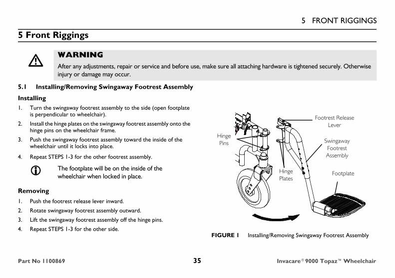
5.1 Installing/Removing Swingaway Footrest Assembly
Installing1. Turn the swingaway footrest assembly to the side (open footplate
is perpendicular to wheelchair).
2. Install the hinge plates on the swingaway footrest assembly onto the hinge pins on the wheelchair frame.
3. Push the swingaway footrest assembly toward the inside of the wheelchair until it locks into place.
4. Repeat STEPS 1-3 for the other footrest assembly.
Removing
1. Push the footrest release lever inward.
2. Rotate swingaway footrest assembly outward.
3. Lift the swingaway footrest assembly off the hinge pins.
4. Repeat STEPS 1-3 for the other side.FIGURE 1 Installing/Removing Swingaway Footrest Assembly
� WARNINGAfter any adjustments, repair or service and before use, make sure all attaching hardware is tightened securely. Otherwise injury or damage may occur.
The footplate will be on the inside of the wheelchair when locked in place.
Footrest Release Lever
Hinge Pins Swingaway
Footrest Assembly
Hinge Plates
Footplate
Part No 1100869 35 Invacare®9000 Topaz™Wheelchair

5 FRONT RIGGINGS5.2 Swingaway Footrest Height Adjustment
1. Remove the swingaway footrest assembly. Refer to Installing/Removing Swingaway Footrest Assembly on page 35.
2. Remove the two bolts and locknuts that secure the lower footrest assembly to the upper footrest support.
3. Reposition the lower footrest assembly to the desired height.
4. Install and securely tighten the two bolts and locknuts.
5. Repeat STEPS 1-4 for the other footrest.
6. Reinstall the swingaway footrest assembly. Refer to Installing/Removing Swingaway Footrest Assembly on page 35.
FIGURE 2 Swingaway Footrest Height Adjustment
5.3 Installing/Removing Elevating Legrest Assembly
Installing
1. Place elevating legrest assembly on the outside of the wheelchair and install the hinge plates onto the hinge pins on the wheelchair frame.
2. Rotate elevating legrest assembly toward the inside of the wheelchair until it locks in place.
3. Repeat STEPS 1 and 2 for the other legrest assembly.
Lay the assembly on a flat surface to simplify this procedure.
Lower Footrest Assembly
Bolts and Locknuts
Upper Footrest Support
For this procedure, refer to FIGURE 3 on page 37.
The footplates will be facing each other when locked in place.
Invacare®9000 Topaz™Wheelchair 36 Part No 1100869

5 FRONT RIGGINGS4. While sitting in the wheelchair, adjust the legrest to the correct height. Refer to Adjusting Elevating Legrest Assembly on page 37.
Removing1. Ensure the elevating legrest is in the lowered position. Refer to
Adjusting Elevating Legrest Assembly on page 37.
2. To release the elevating legrest assembly push the legrest release handle toward the inside of the wheelchair (facing the front of the wheelchair) and swing the legrest assembly to the outside of the wheelchair.
3. Lift the elevating legrest assembly off the hinge pins.
FIGURE 3 Installing/Removing Elevating Legrest Assembly
5.4 Adjusting Elevating Legrest Assembly
Adjusting Footrest Height1. While sitting in the wheelchair, remove the two bolts and locknuts securing the lower footrest assembly to the elevating legrest assembly and
move the lower footrest assembly up or down until the desired height is achieved.
2. Secure the lower footrest assembly to the elevating legrest assembly with the two bolts and locknuts. Securely tighten.
3. Repeat STEPS 1-2 on remaining legrest assembly.
Adjusting Calfpad1. Remove the two mounting screws securing the calfpad to the calfpad support of the elevating legrest assembly.
2. Slide the Calfpad up or down until the desired position is obtained.
Elevating Legrest Assembly
Legrest Release LeverHinge Pins
For this procedure, refer to FIGURE 4 on page 38.
Part No 1100869 37 Invacare®9000 Topaz™Wheelchair
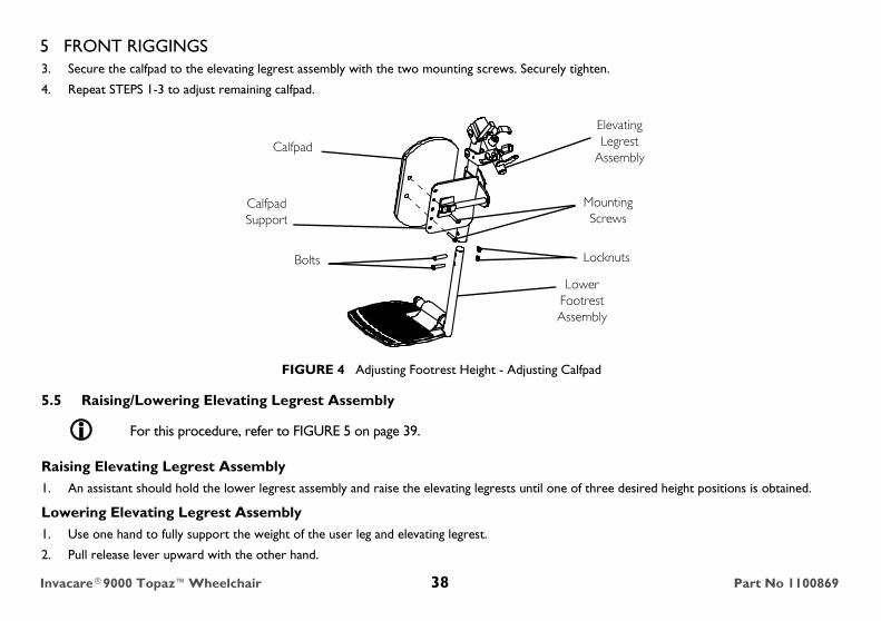
5 FRONT RIGGINGS3. Secure the calfpad to the elevating legrest assembly with the two mounting screws. Securely tighten.
4. Repeat STEPS 1-3 to adjust remaining calfpad.
FIGURE 4 Adjusting Footrest Height - Adjusting Calfpad
5.5 Raising/Lowering Elevating Legrest Assembly
Raising Elevating Legrest Assembly1. An assistant should hold the lower legrest assembly and raise the elevating legrests until one of three desired height positions is obtained.
Lowering Elevating Legrest Assembly1. Use one hand to fully support the weight of the user leg and elevating legrest.
2. Pull release lever upward with the other hand.
For this procedure, refer to FIGURE 5 on page 39.
Calfpad Support
Lower Footrest Assembly
LocknutsBolts
Mounting Screws
Elevating Legrest
AssemblyCalfpad
Invacare®9000 Topaz™Wheelchair 38 Part No 1100869

5 FRONT RIGGINGS3. Gently, lower user leg and elevating legrest down to desired position.
4. Repeat STEPS 1-3 for remaining elevating legrest.
FIGURE 5 Raising/Lowering Elevating Legrest Assembly
5.6 Installing Calf Strap
1. Remove calf strap from packaged container if it is not already secured to the footrest.
2. Secure one side of the calf strap around each footrest.
FIGURE 6 Installing Calf Strap
Elevating Legrest
Lower Legrest Assembly
Release Lever
Footrest
Calf Strap
Footrest
Part No 1100869 39 Invacare®9000 Topaz™Wheelchair
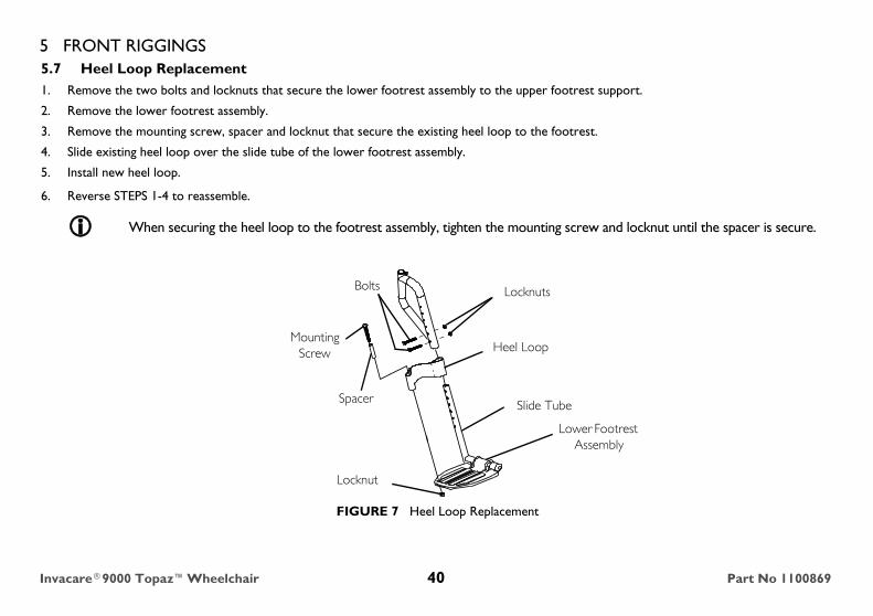
5 FRONT RIGGINGS5.7 Heel Loop Replacement1. Remove the two bolts and locknuts that secure the lower footrest assembly to the upper footrest support.
2. Remove the lower footrest assembly.
3. Remove the mounting screw, spacer and locknut that secure the existing heel loop to the footrest.
4. Slide existing heel loop over the slide tube of the lower footrest assembly.
5. Install new heel loop.
6. Reverse STEPS 1-4 to reassemble.
FIGURE 7 Heel Loop Replacement
When securing the heel loop to the footrest assembly, tighten the mounting screw and locknut until the spacer is secure.
Locknuts
Mounting Screw
Spacer
Lower Footrest Assembly
Slide Tube
Heel Loop
Bolts
Locknut
Invacare®9000 Topaz™Wheelchair 40 Part No 1100869
6 ARMS
6 Arms
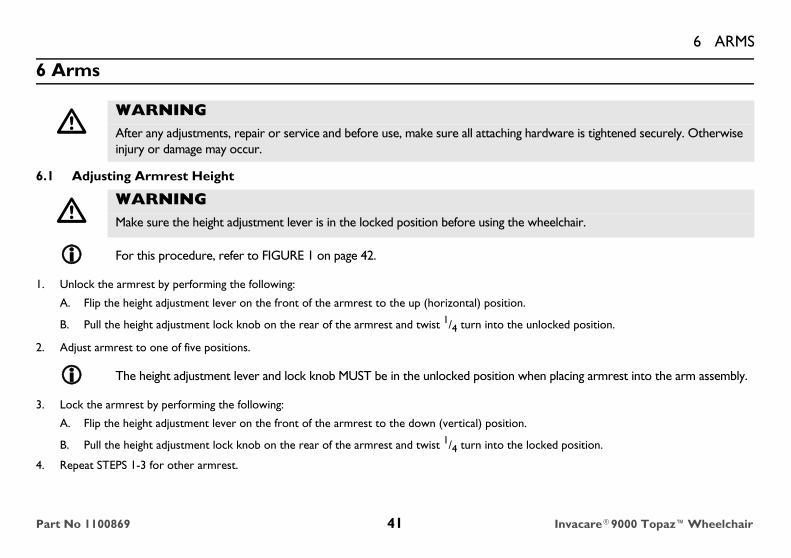
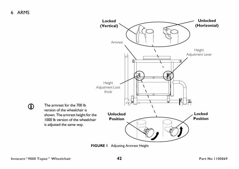
6.1 Adjusting Armrest Height
1. Unlock the armrest by performing the following:
A. Flip the height adjustment lever on the front of the armrest to the up (horizontal) position.
B. Pull the height adjustment lock knob on the rear of the armrest and twist 1/4 turn into the unlocked position.
2. Adjust armrest to one of five positions.
3. Lock the armrest by performing the following:
A. Flip the height adjustment lever on the front of the armrest to the down (vertical) position.
B. Pull the height adjustment lock knob on the rear of the armrest and twist 1/4 turn into the locked position.
4. Repeat STEPS 1-3 for other armrest.
� WARNINGAfter any adjustments, repair or service and before use, make sure all attaching hardware is tightened securely. Otherwise injury or damage may occur.
� WARNINGMake sure the height adjustment lever is in the locked position before using the wheelchair.
For this procedure, refer to FIGURE 1 on page 42.
The height adjustment lever and lock knob MUST be in the unlocked position when placing armrest into the arm assembly.
Part No 1100869 41 Invacare®9000 Topaz™Wheelchair
6 ARMS
FIGURE 1 Adjusting Armrest Height
Armrest
Height Adjustment Lock
Knob
Unlocked Position
Locked Position
Height Adjustment Lever
Unlocked (Horizontal)
Locked (Vertical)
The armrest for the 700 lb version of the wheelchair is shown. The armrest height for the 1000 lb version of the wheelchair is adjusted the same way.
Invacare®9000 Topaz™Wheelchair 42 Part No 1100869

6 ARMS6.2 Replacing Desk/Full Length Armrest Pad1. Remove the mounting screws that secure the armrest pad to the armrest assembly.
2. Replace armrest pad and securely tighten with the existing mounting screws.
FIGURE 2 Replacing Desk/Full Length Armrest Pad
6.3 Removing or Replacing Armrest
� WARNINGMake sure the armrest release lever is in the locked position before using the wheelchair.
For this procedure, refer to FIGURE 3 on page 44.
Armrest Pad
Mounting Screws
Armrest Assembly
The armrest for the 700 lb version of the wheelchair is shown. The armrest height for the 1000 lb version of the wheelchair is replaced the same way.
Part No 1100869 43 Invacare®9000 Topaz™Wheelchair
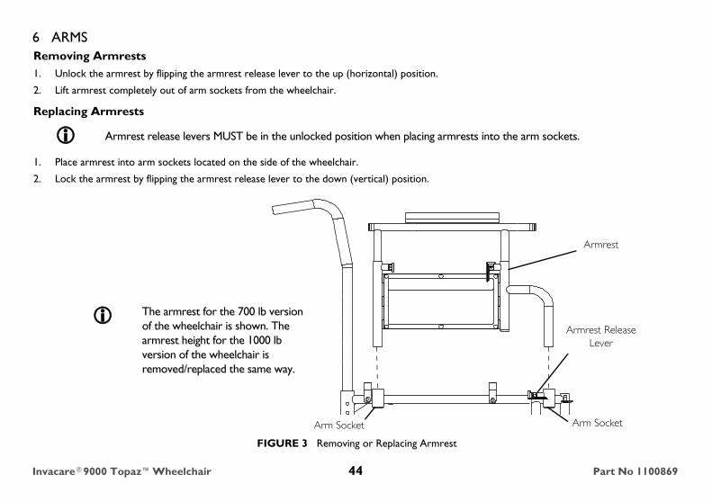
6 ARMSRemoving Armrests1. Unlock the armrest by flipping the armrest release lever to the up (horizontal) position.
2. Lift armrest completely out of arm sockets from the wheelchair.
Replacing Armrests
1. Place armrest into arm sockets located on the side of the wheelchair.
2. Lock the armrest by flipping the armrest release lever to the down (vertical) position.
FIGURE 3 Removing or Replacing Armrest
Armrest release levers MUST be in the unlocked position when placing armrests into the arm sockets.
Armrest
Armrest Release Lever
Arm SocketArm Socket
The armrest for the 700 lb version of the wheelchair is shown. The armrest height for the 1000 lb version of the wheelchair is removed/replaced the same way.
Invacare®9000 Topaz™Wheelchair 44 Part No 1100869
7 SEAT AND BACK
7 Seat and Back
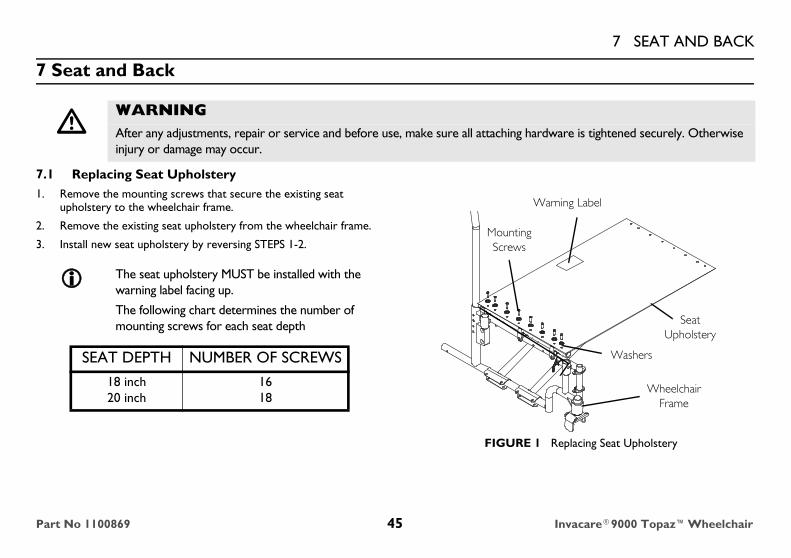
7.1 Replacing Seat Upholstery1. Remove the mounting screws that secure the existing seat
upholstery to the wheelchair frame.
2. Remove the existing seat upholstery from the wheelchair frame.
3. Install new seat upholstery by reversing STEPS 1-2.
FIGURE 1 Replacing Seat Upholstery
� WARNINGAfter any adjustments, repair or service and before use, make sure all attaching hardware is tightened securely. Otherwise injury or damage may occur.
The seat upholstery MUST be installed with the warning label facing up.
The following chart determines the number of mounting screws for each seat depth
SEAT DEPTH NUMBER OF SCREWS18 inch20 inch
1618
Mounting Screws
Washers
Seat Upholstery
Wheelchair Frame
Warning Label
Part No 1100869 45 Invacare®9000 Topaz™Wheelchair

7 SEAT AND BACK7.2 Replacing Back Upholstery
1. Remove the eighteen mounting screws and washers that secure the existing back upholstery to the back canes.
2. Install and securely tighten the new back upholstery to the back canes with the eighteen mounting screws and washers starting with the top hole of the back cane.
FIGURE 2 Replacing Back Upholstery
7.3 Adjusting Back Height
1. Remove the four mounting screws and locknuts that secure the two back canes to the wheelchair frame.
2. Remove the bottom two back upholstery mounting screws from the cane.
3. Reposition the back canes to one of three height adjustment positions:
Back Cane
Mounting Screws
Washers
Back Upholstery
For this procedure, refer to FIGURE 3 on page 47.
HOLE NUMBER 1 & 2 2 & 3 3 & 4
BACK HEIGHT 16 inches 17 inches 18 inches
Holes numbered from bottom to top for reference only. (There are no numbers on the back canes).
The mounting screws must be securely tightened into the threaded mounting holes of the wheelchair frame before installing the locknuts.
Invacare®9000 Topaz™Wheelchair 46 Part No 1100869

7 SEAT AND BACK4. Reinstall the four (4) mounting screws through the threaded mounting holes of the wheelchair frame and the back cane. Securely tighten.
5. Reinstall the four locknuts. Securely tighten
6. Reinstall the two back upholstery mounting screws. Securely tighten.
FIGURE 3 Adjusting Back Height
7.4 Adjusting Seat Depth
7.5 Adjusting Seat Width
� WARNINGAdjusting the seat depth of the 9000 Topaz wheelchair must be performed by a qualified technician. Contact dealer/Invacare.
� WARNINGAdjusting the seat width of the 9000 Topaz wheelchair must be performed by a qualified technician. Contact dealer/Invacare.
Height Adjustment Positions
Wheelchair Frame
Back Cane
4
3
2
1
The two mounting screws and locknuts that secure the back cane to the wheelchair frame are not shown for clarity.
Part No 1100869 47 Invacare®9000 Topaz™Wheelchair

8 REAR WHEELS
Invacare®9000 Topaz™Wheelchair 48 Part No 1100869
8 Rear Wheels
8.1 Removing/Installing Rear Wheels
1. Place the wheelchair frame up on blocks so that the rear wheels are off the ground.
2. Remove the dust cap (if applicable), mounting screw, locknut and two washers (if present) that secure the rear wheel and axle spacer to the wheelchair.
3. Repeat STEP 2 for the opposite rear wheel.
4. To reinstall the rear wheel onto the wheelchair, reverse STEP 2.
FIGURE 1 Removing/Installing Rear Wheels
� WARNINGAfter any adjustments, repair or service and before use, make sure all attaching hardware is tightened securely. Otherwise injury or damage may occur.
� WARNINGChanging the rear wheel size or changing the seat-to-floor height MUST be performed only by a qualified technician.
If replacing the same size rear wheel, note the mounting position on the wheelchair frame for proper reinstallation of the new rear wheel.
Rear wheel mounting hardware may include two washers for each wheel. If washers are present, note the location and ensure the washers are installed when reinstalling the rear wheel.
Make sure axle spacer is between rear wheel and wheelchair frame.
Locknut
Axle Mounting Positions
Axle Spacer
Wheelchair Frame
Mounting Screw
Rear Wheel
Washers(if Present)
9 FRONT CASTERS
9 Front Casters
9.1 Installing/Replacing Six or Eight-inch Front Casters and Forks
1. Remove the dust cover.
2. Remove the locknut and washer that secures the fork to the caster headtube.
3. Drop the front caster and fork out of the caster headtube.
4. Slide in the new front caster and fork.
5. Reassemble by reversing STEPS 1-2.
6. Repeat STEPS 1-5 for the opposite front caster.
� WARNINGAfter any adjustments, repair or service and before use, make sure all attaching hardware is tightened securely. Otherwise injury or damage may occur.
� WARNINGIf converting from six-inch caster to an eight-inch caster or vice versa, there are seat-to-floor height adjustments that must be made. Therefore, this procedure MUST be performed by a qualified technician.
For this procedure, refer to FIGURE 1 on page 50.
This procedure can be performed if replacing the exact same size front caster.
Part No 1100869 49 Invacare®9000 Topaz™Wheelchair

9 FRONT CASTERS7. To properly tighten caster journal system and guard against flutter,
perform the following check:
A. Tip back of wheelchair to floor.B. Simultaneously pivot both forks and casters to the top of their
arc.C. Let casters drop to the bottom of their arc (wheels should
swing once to one-side, then immediately rest in a straight downward position).
D. Adjust locknuts according to freedom of caster swing.8. Test wheelchair for maneuverability.
9. Readjust locknuts if necessary.
10. Repeat STEPS 7-9 until correct.
11. Snap dust cover over the locknut and stem.
FIGURE 1 Installing/Replacing Six or Eight-inch Front Casters and Forks
9.2 Front Caster Mounting Adjustments
Caster Headtube
Front Caster Fork
Washers
Locknut
Dust Cover
� WARNINGAdjusting front caster mountings MUST be performed by a qualified technician. Contact dealer/Invacare.
Invacare®9000 Topaz™Wheelchair 50 Part No 1100869
10 ANTI-TIPPERS/WHEEL LOCKS
10 Anti-tippers/Wheel Locks
10.1 Installing Anti-Tippers
� WARNINGAfter any adjustments, repair or service and before use, make sure all attaching hardware is tightened securely. Otherwise injury or damage may occur.
� WARNINGAnti-tippers are specific to the different rear wheels and/or seat-to-floor heights. Refer to the chart in Installing Anti-Tippers on page 51 for correct usage and adjustment. If these requirements cannot be achieved, DO NOT use the wheelchair. Contact an Invacare dealer or qualified technician. Any changes to the seat-to-floor angle or seat-to-floor height may require different anti-tippers. The correct anti-tippers MUST be ordered to maintain a 3.81 x 5.08 cm (1½ to 2 in) ground clearance.Inasmuch as the anti-tippers are an option on this wheelchair (you may order with or without the anti-tippers), Invacare strongly recommends ordering the anti-tippers as an additional safeguard for the wheelchair user.Invacare strongly recommends that anti-tippers be used at all times.The manual wheelchair is intended for indoor and outdoor use on firm surfaces. When outdoors on wet, soft ground or on gravel surfaces, anti-tippers may not provide the same level of protection against tip over. DO NOT operate on soft surfaces such as sand, grass or gravel.
For this procedure, refer to FIGURE 1 on page 53.
To ensure the correct model anti-tipper is used refer to the following chart. Measurements for anti-tippers are approximate.
Part No 1100869 51 Invacare®9000 Topaz™Wheelchair

10 ANTI-TIPPERS/WHEEL LOCKS1. Insert the anti-tippers with the anti-tipper wheels positioned according to the following chart:
Wheelchair Seat-to-Floor Height (inches)
ANTI-TIPPER WHEEL POSITION
19½
17½
15½
Anti-Tipper (1102147)
Wheelchair Frame
Anti-tipper Height
3 3/8 inches
Wheelchair Frame
Anti-Tipper (1102146)Anti-tipper Height
11/4 inches
Wheelchair Frame
Anti-Tipper (1102146)
Anti-tipper Height
11/4 inches
When installing/using anti-tipper 1102146 on the 9000 Topaz wheelchair with a seat-to-floor height of 15½ inches, the anti-tipper wheels must be pointed up away from the ground/floor.
Invacare®9000 Topaz™Wheelchair 52 Part No 1100869

10 ANTI-TIPPERS/WHEEL LOCKS2. Secure the anti-tipper to the wheelchair frame with the locking pin.
3. Ensure that the locking pin protrudes through both the anti-tipper and the wheelchair frame.
4. Repeat STEPS 1-3 to install the remaining anti-tipper.
FIGURE 1 Installing Anti-Tippers
10.2 Using/Adjusting Wheel Locks
Using Wheel Locks
1. Ensure the wheelchair is not moving before engaging the wheel locks.
2. Depending on the model of wheel lock installed on the wheelchair, perform one (1) of the following:
• Push-to-Lock - To engage, push the wheel lock handle forward.
• Pull-to-Lock - To engage, pull the wheel lock handle backward.
3. Disengage the wheel locks by reversing STEP 2.
Locking PinWheelchair Frame
Anti-Tipper
� WARNINGDO NOT attempt to stop a moving wheelchair with wheel locks. Wheel locks are not brakes.
For this procedure, refer to FIGURE 2 on page 54.
Position wheelchair on a flat, level surface to perform this procedure.
Part No 1100869 53 Invacare®9000 Topaz™Wheelchair
10 ANTI-TIPPERS/WHEEL LOCKS
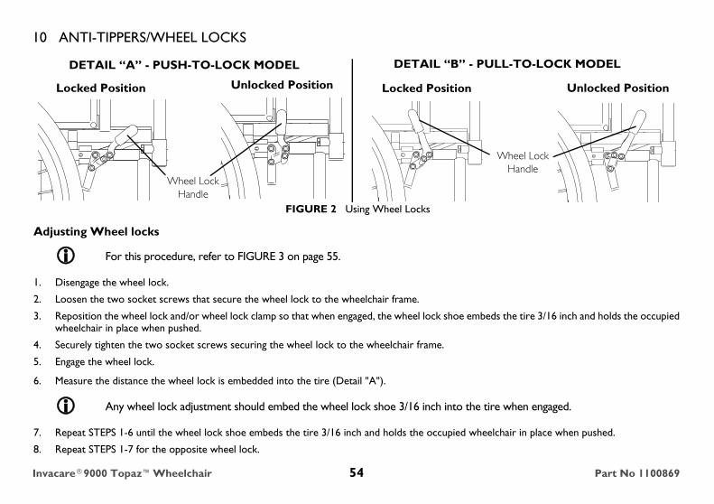
FIGURE 2 Using Wheel Locks
Adjusting Wheel locks
1. Disengage the wheel lock.
2. Loosen the two socket screws that secure the wheel lock to the wheelchair frame.
3. Reposition the wheel lock and/or wheel lock clamp so that when engaged, the wheel lock shoe embeds the tire 3/16 inch and holds the occupied wheelchair in place when pushed.
4. Securely tighten the two socket screws securing the wheel lock to the wheelchair frame.
5. Engage the wheel lock.
6. Measure the distance the wheel lock is embedded into the tire (Detail "A").
7. Repeat STEPS 1-6 until the wheel lock shoe embeds the tire 3/16 inch and holds the occupied wheelchair in place when pushed.
8. Repeat STEPS 1-7 for the opposite wheel lock.
For this procedure, refer to FIGURE 3 on page 55.
Any wheel lock adjustment should embed the wheel lock shoe 3/16 inch into the tire when engaged.
DETAIL “A” - PUSH-TO-LOCK MODEL DETAIL “B” - PULL-TO-LOCK MODEL
Unlocked Position Unlocked PositionLocked Position Locked Position
Wheel Lock Handle
Wheel Lock Handle
Invacare®9000 Topaz™Wheelchair 54 Part No 1100869

10 ANTI-TIPPERS/WHEEL LOCKS9. Engage both wheel locks and ensure the occupied wheelchair is held in place when pushed.
FIGURE 3 Adjusting Wheel locks
� WARNINGIf wheel locks do not hold the occupied wheelchair in place, contact a qualified technician. Otherwise, injury or damage may occur.
DETAIL “A” - WHEEL LOCK SHOE ENGAGEMENT
3/16 inch
Wheel Lock Shoe
Tire
Socket Screws
Wheel Lock
Wheel Lock Clamp
Wheelchair Frame
Wheel Lock Shoe
Rear Wheel
Part No 1100869 55 Invacare®9000 Topaz™Wheelchair
11 OPTIONS
11 Options
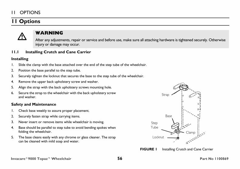
11.1 Installing Crutch and Cane Carrier
Installing1. Slide the clamp with the base attached over the end of the step tube of the wheelchair.
2. Position the base parallel to the step tube.
3. Securely tighten the locknut that secures the base to the step tube of the wheelchair.
4. Remove the upper back upholstery screw and washer.
5. Align the strap with the back upholstery screws mounting hole.
6. Secure the strap to the wheelchair with the back upholstery screw and washer.
Safety and Maintenance
1. Check base weekly to assure proper placement.
2. Securely fasten strap while carrying items.
3. Never insert or remove items while wheelchair is moving.
4. Base should be parallel to step tube to avoid bending spokes when folding the wheelchair.
5. The base cleans easily with any chrome or glass cleaner. The strap can be cleaned with mild soap and water.
FIGURE 1 Installing Crutch and Cane Carrier
� WARNINGAfter any adjustments, repair or service and before use, make sure all attaching hardware is tightened securely. Otherwise injury or damage may occur.
Locknut
Step Tube
Clamp
Base
Strap
Invacare®9000 Topaz™Wheelchair 56 Part No 1100869
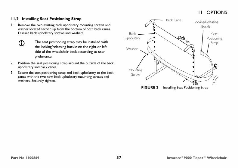
11 OPTIONS11.2 Installing Seat Positioning Strap
1. Remove the two existing back upholstery mounting screws and washer located second up from the bottom of both back canes. Discard back upholstery screws and washers.
2. Position the seat positioning strap around the outside of the back upholstery and back canes.
3. Secure the seat positioning strap and back upholstery to the back canes with the two new back upholstery mounting screws and washers. Securely tighten.
FIGURE 2 Installing Seat Positioning Strap
The seat positioning strap may be installed with the locking/releasing buckle on the right or left side of the wheelchair back according to user preference.
Back Upholstery
Mounting Screw
Washer
Seat Positioning
Strap
Locking/Releasing Buckle
Back Cane
Part No 1100869 57 Invacare®9000 Topaz™Wheelchair

11 OPTIONS11.3 Wheel Lock Extension Handle
1. Remove the existing rubber tip from the wheel lock handle. Discard rubber tip.
2. Secure the wheel lock extension handle to the wheelchair frame by wrapping the elastic cord around the wheelchair frame.
3. Pass the wheel lock extension handle through the loop end of the elastic cord.
4. Slide the wheel lock extension handle on to the wheel lock handle.
5. Repeat STEPS 1-4 for the remaining wheel lock.
FIGURE 3 Wheel Lock Extension Handle
� WARNINGIf the wheelchair is equipped with push to lock wheel locks, elevating legrests, and wheel lock extension handles, the wheel lock extension handles MUST be removed before swinging the elevating legrests to the side, otherwise injury or damage may result. Interference between the top of the elevating legrest and the wheel lock extension handle causes the wheel lock to disengage.
Elastic Cord (Loop End)
Wheelchair Frame
Wheel Lock Handle
Wheel Lock Extension Handle
Invacare®9000 Topaz™Wheelchair 58 Part No 1100869

11 OPTIONS11.4 Installing/Removing Solid Seat Insert
Installing
1. Position the solid seat insert so that it is fully supported by the seat rails and the back edge of the solid seat insert is touching the back canes.
Removing
1. Firmly grasp the solid seat insert and lift away from the seat upholstery.
11.5 Installing/Removing Solid Back Insert
Installing
1. Position the solid back insert between the back canes.
2. Wrap the two fastening straps around the back canes.
3. Securely fasten with two snaps.
Removing
1. Release the two snaps securing the two fastening straps around the back canes.
2. Remove the solid back insert.
FIGURE 4 Installing/Removing Solid Seat Insert and Installing/Removing Solid Back Insert
Back Canes
Seat Rail
Solid Seat Insert
Seat Rail
Back Canes
Solid Back Insert
Fastening Strap
Snaps
Solid Seat Insert
Solid Back Insert
Part No 1100869 59 Invacare®9000 Topaz™Wheelchair

11 OPTIONS11.6 Installing O2 Holder/Telescoping I.V. Rod with O2 Holder
1. Slide the mounting bracket over the left side step tube of the wheelchair frame.
2. Secure the mounting bracket to the wheelchair frame with the hex screw, spacer and locknut.
3. Telescoping I.V. with O2 holder only: Secure the top of the telescoping I.V. rod holder to the wheelchair frame with a tie wrap.
FIGURE 5 Installing O2 Holder/Telescoping I.V. Rod with O2 Holder
Locknut Step TubeSpacer
Hex Screw
Mounting Bracket
Tie Wrap
Telescoping I.V. Rod/O2 Holder
DETAIL “A” - TELESCOPING I.V. ROD/O2 HOLDER
Mounting Bracket
SpacerStep Tube
Locknut
Hex Screw
O2 Holder
DETAIL “B” - O2 HOLDER
Invacare®9000 Topaz™Wheelchair 60 Part No 1100869
11 OPTIONS11.7 Installing Telescoping I.V. Rod
Mounting Instructions
1. Loosely secure the two bracket plates to the lower mounting bracket using the short spacer, long spacer and two mounting screws and locknuts (Detail “A”).
2. Slide the lower mounting bracket over the left side step tube of the wheelchair frame, so that the step tube is positioned between the two spacers.
3. Remove the existing top left upholstery mounting screw and washer. Discard existing upholstery mounting screw and washer.
4. Secure the upper mounting bracket and back upholstery to the back cane using the new upholstery mounting screw and washer.
5. Secure the lower mounting bracket to the wheelchair frame by securely tightening the two (2) hex screws and locknuts on the mounting bracket.
6. Loosen the adjustment knob and position the IV rod to the desired height and securely tighten the adjustment knob.
For this procedure, refer to FIGURE 6 on page 62.
The telescoping I.V. rod is factory set for installation on the left side of the wheelchair. If necessary to install on the right side, refer to Repositioning Upper Mounting Bracket on page 63.
Ensure the telescoping I.V. rod is vertical before securing the lower mounting bracket to the step tube.
Part No 1100869 61 Invacare®9000 Topaz™Wheelchair
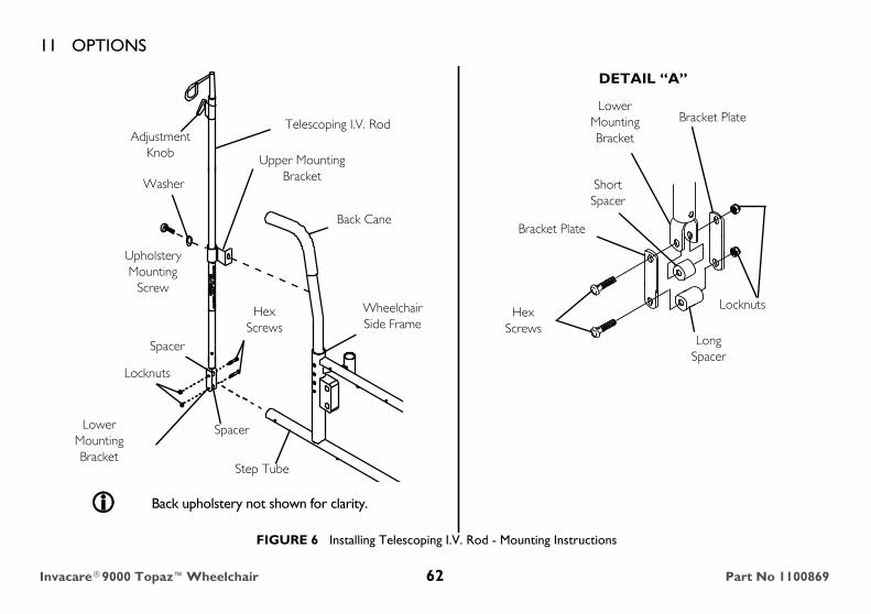
11 OPTIONS
FIGURE 6 Installing Telescoping I.V. Rod - Mounting Instructions
Washer
Locknuts
Upholstery Mounting
Screw
Spacer
Step Tube
Lower Mounting Bracket
Wheelchair Side Frame
Back Cane
Locknuts
Adjustment Knob Upper Mounting
Bracket
Telescoping I.V. Rod
Hex Screws
Spacer
Lower Mounting Bracket
Hex Screws
Long Spacer
Short Spacer
Bracket Plate
Bracket Plate
DETAIL “A”
Back upholstery not shown for clarity.
Invacare®9000 Topaz™Wheelchair 62 Part No 1100869

11 OPTIONSRepositioning Upper Mounting Bracket
1. With the telescoping I.V. rod in the lowest position, align the hole of the outer tube with the phillips screw of the inner tube.
2. Remove phillips screw and set aside.
3. Remove the inner tube from the outer tube.
4. Firmly grasp the height adjustment assembly and pull to remove from the outer tube.
5. Slide the upper mounting bracket up off the outer tube.
6. Rotate the upper mounting bracket 180° and reinstall onto the outer tube.
7. Reverse STEPS 1-5 to reassemble the telescoping I.V. rod.
For this procedure, refer to FIGURE 7 on page 64.
This adjustment is required if the telescoping I.V. rod must be mounted on the right side of the wheelchair.
Part No 1100869 63 Invacare®9000 Topaz™Wheelchair

11 OPTIONS
FIGURE 7 Installing Telescoping I.V. Rod - Repositioning Upper Mounting Bracket
Hole
Outer Tube
Phillips Screw
Upper Mounting Bracket (Shown Rotated 180°)
Inner Tube
Outer Tube
Height Adjustment Assembly
Invacare®9000 Topaz™Wheelchair 64 Part No 1100869
11 OPTIONSSafety and Maintenance1. Make sure the telescoping I.V. rod is tightly locked before placing I.V. medication on the rod.
2. The telescoping I.V. rod is designed for the specific purpose of supporting I.V. medication only. DO NOT use it to support objects other than I.V. medication.
3. Check weekly to make sure the telescoping I.V. rod/O2 holder is tightly secured to the wheelchair frame. If there is any looseness whatsoever, DO NOT use until the corrective adjustments have been made.
4. The telescoping I.V. rod/O2 holders clean easily with any household glass-type cleaner.
11.8 Installing/Removing Push Bar
Installing Push Bar
1. Insert one push bar support into one back cane handle.
2. Align the remaining push bar support with the remaining back cane handle.
3. Insert the push bar support into the back cane handle. Securely tighten both lock knobs.
Removing Push Bar 1. Completely unthread both lock knobs.
2. Firmly grasp both ends of the push bar and pull to remove the push bar from the back cane handles.
For this procedure, refer to FIGURE 8 on page 66.
The 9000 Topaz is folded for either storage or transporting. The push bar must be removed before folding the wheelchair.
It may be necessary to move the back cane side-to-side in order to align the remaining push bar support with the back cane handle.
Part No 1100869 65 Invacare®9000 Topaz™Wheelchair
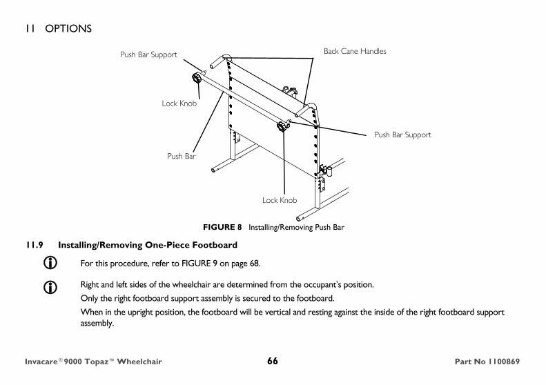
11 OPTIONS
FIGURE 8 Installing/Removing Push Bar
11.9 Installing/Removing One-Piece Footboard
For this procedure, refer to FIGURE 9 on page 68.
Right and left sides of the wheelchair are determined from the occupant’s position.
Only the right footboard support assembly is secured to the footboard.
When in the upright position, the footboard will be vertical and resting against the inside of the right footboard support assembly.
Push Bar Support
Lock Knob
Push Bar
Lock Knob
Push Bar Support Back Cane Handles
Invacare®9000 Topaz™Wheelchair 66 Part No 1100869
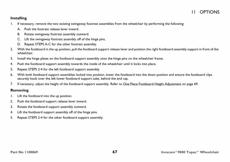
11 OPTIONSInstalling1. If necessary, remove the two existing swingaway footrest assemblies from the wheelchair by performing the following:
A. Push the footrest release lever inward.B. Rotate swingaway footrest assembly outward.C. Lift the swingaway footrest assembly off of the hinge pins.D. Repeat STEPS A-C for the other footrest assembly.
2. With the footboard in the up position, pull the footboard support release lever and position the right footboard assembly support in front of the wheelchair.
3. Install the hinge plates on the footboard support assembly onto the hinge pins on the wheelchair frame.
4. Push the footboard support assembly towards the inside of the wheelchair until it locks into place.
5. Repeat STEPS 2-4 for the left footboard support assembly.
6. With both footboard support assemblies locked into position, lower the footboard into the down position and ensure the footboard clips securely hook over the left lower footboard support tube, behind the end cap.
7. If necessary, adjust the height of the footboard support assembly. Refer to One Piece Footboard Height Adjustment on page 69.
Removing1. Lift the footboard into the up position.
2. Push the footboard support release lever inward.
3. Rotate the footboard support assembly outward.
4. Lift the footboard support assembly off of the hinge pins.
5. Repeat STEPS 2-4 for the other footboard support assembly.
Part No 1100869 67 Invacare®9000 Topaz™Wheelchair
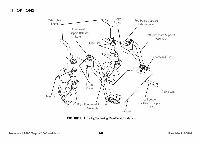
11 OPTIONS
FIGURE 9 Installing/Removing One-Piece Footboard
Footboard Support Release
Lever
Wheelchair Frame
Hinge Pins
Hinge Plates
Right Footboard Support Assembly
Footboard
Left Lower Footboard Support
Tube
End Cap
Footboard Clips
Left Footboard Support Assembly
Footboard Support Release Lever
Hinge Pins
Hinge Plates
Invacare®9000 Topaz™Wheelchair 68 Part No 1100869

11 OPTIONS11.10 One Piece Footboard Height Adjustment
1. Remove the footboard support assembly. Refer to Installing/Removing One-Piece Footboard on page 66.
2. Remove the two bolts and locknuts that secure the lower footboard support tube to the upper footboard support.
3. Reposition the lower footboard support tube to the desired height.
4. Using the two bolts and locknuts, secure the lower footboard support tube to the upper footboard support. Securely tighten.
5. Repeat STEPS 2-4 to adjust the remaining footboard support assembly.
6. Reinstall the footboard support assembly. Refer to Installing/Removing One-Piece Footboard on page 66.
For this procedure, refer to FIGURE 10 on page 70.
Lay the assembly on a flat surface to simplify this procedure.
Ensure both footboard supports are adjusted to the same height.
Part No 1100869 69 Invacare®9000 Topaz™Wheelchair
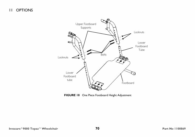
11 OPTIONS
FIGURE 10 One Piece Footboard Height Adjustment
Upper Footboard Supports
BoltsLocknuts
Lower Footboard
tubeFootboard
Lower Footboard
Tube
Locknuts
Invacare®9000 Topaz™Wheelchair 70 Part No 1100869

11 OPTIONSNOTES
Part No 1100869 71 Invacare®9000 Topaz™Wheelchair

Invacare Corporation
USAOne Invacare WayElyria, Ohio USA44036-2125800-333-6900
Canada570 Matheson Blvd E Unit 8Mississauga OntarioL4Z 4G4 Canada800-668-5324
Part No 1100869 Rev I~01 - 11/17/15 www.invacare.com
Making Life’s Experiences Possible™