Embed Size (px)
Citation preview

Smartek Giganetix Camera FamilyGigE Vision digital camera
User ManualDocument version 1.2, last changed: 13. Jun. 2011

Table of Contents1.Overview.......................................................................................................................................1
1.1.Precautions............................................................................................................................1
1.2.Description.............................................................................................................................2
1.3.Key benefits and features......................................................................................................3
1.4.Supported industry standards................................................................................................4
1.4.1.GigE Vision.....................................................................................................................4
1.4.2.GenICam........................................................................................................................5
1.4.3.Standard Features Naming Convention (SFNC)............................................................5
1.4.4.C-mount.........................................................................................................................6
1.5.Connections...........................................................................................................................6
1.5.1.Connecting scheme........................................................................................................6
1.5.2.Ethernet connector.........................................................................................................7
1.5.3.Ethernet status...............................................................................................................7
1.5.4.Power connector............................................................................................................8
1.5.5.Trigger input (all models)................................................................................................9
1.5.5.1.Scheme (all models)...............................................................................................9
1.5.6.Digital output (all models).............................................................................................10
1.5.7.Scheme (all models).....................................................................................................10
1.6.Mechanical and electrical specifications...............................................................................11
1.7.Software specifications.........................................................................................................11
1.8.Dimensions..........................................................................................................................12
2.Camera models...........................................................................................................................13
2.1.EMI and ESD consideration.................................................................................................13
2.2.Sensor information and technical specification (all models separate)..................................13
2.2.1.GC1281M.....................................................................................................................14
2.2.2.GC2041C.....................................................................................................................15
2.2.3.GC2591M / GC2591C..................................................................................................16
2.2.4.GC3851M / GC3851C..................................................................................................17
2.2.5.GC651M / GC651C......................................................................................................18
2.2.6.GC652M / GC652C......................................................................................................19
2.2.7.GC653M / GC653C......................................................................................................20
2.2.8.GC781M / GC781C......................................................................................................21
2.2.9.GC1031M / GC1031C..................................................................................................22
2.2.10.GC1291M / GC1291C................................................................................................23
2.2.11.GC1391M / GC1391C................................................................................................24
2.2.12.GC1392M / GC1392C................................................................................................25
2.2.13.GC1621M / GC1621C................................................................................................26

2.2.14.GC2441M / GC2441C................................................................................................27
2.2.15.GC1021M / GC1021C................................................................................................28
2.2.16.GC1601M / GC1601C................................................................................................29
2.2.17.GC1921M / GC1921C................................................................................................29
3.GigEVisionSDK library for Windows............................................................................................31
3.1.GigEVisionSDK library installation.......................................................................................31
3.2.Connecting camera..............................................................................................................34
3.2.1.Connecting peer to peer with Ethernet cable................................................................34
3.2.2.Connecting GigEVisionClient with the camera.............................................................36
3.3.Filter driver installation.........................................................................................................38
4.GigEVisionClient features............................................................................................................41
4.1.Acquisition control................................................................................................................41
4.1.1.Acquisition mode..........................................................................................................42
4.1.2.Trigger mode................................................................................................................42
4.1.3.Trigger source..............................................................................................................42
4.1.4.Trigger activation..........................................................................................................43
4.1.5.Exposure......................................................................................................................43
4.1.6.Test your camera..........................................................................................................44
4.2.External trigger....................................................................................................................45
4.2.1.Trigger latency..............................................................................................................45
4.2.2.Trigger delay................................................................................................................45
4.2.3.Trigger edge.................................................................................................................45
4.2.4.Trigger debouncer........................................................................................................46
4.3.Parallel exposure and sensor readout..................................................................................48
4.4.Acquisition frame rate..........................................................................................................48
4.5.Inter packet delay.................................................................................................................49
4.5.1.Setting inter packet delay.............................................................................................50
4.6.Area Of Interest (AOI)..........................................................................................................51
4.6.1.Setting Area Of Interest................................................................................................52
4.7.Analog control......................................................................................................................53
4.7.1.Gain..............................................................................................................................53
4.7.2.Black level....................................................................................................................53
4.8.IR filter and IR-cut filter (optional)........................................................................................54
4.9.Firmware update..................................................................................................................55
5.FAQ - Frequently asked questions..............................................................................................57
6.CE Conformity declaration...........................................................................................................58
7.Smartek Information....................................................................................................................59

Giganetix camera family – User Manual
1. Overview1.1. Precautions
Due to the ultra small compact housing of the camera, it has a tendency to develop high temperature. To maintain optimal working temperature mount the camera on a metal surface.
Do not attempt to disassemble this camera, there are sensitive optical parts inside. Tampering with it could lead to permanent damage.
Do not expose this camera to rain or moisture. This device is not intended to work under water.
Do not face this camera towards the sun, extremely bright light or light reflecting objects. Even when this camera is not in use, put the supplied lens cap on the lens mount.
Handle this camera with the maximum care. Do not throw the device, there are fragile glass parts inside.
Operate this camera only from the type of power source indicated on the camera. Operating the camera exceeding specifications can damage the camera permanently (see 2.1 Mechanical and electrical specifications).
13. Jun. 2011 1

Giganetix camera family – User Manual
1.2. Description
Innovative Gigabit Ethernet technology digital camera line up specially designed to meet demanding high quality image machine vision applications conforming to industrial GigE Vision standard. Compact housing that fits almost every space critical application. Fine selection of Sony, Aptina and Kodak CCD and CMOS sensors delivers images with high sensitivity and low noise. Excellent price to performance ratio makes this portfolio perfect choice for every demanding user.
The Smartek Giganetix camera family are an affordable, easy to use digital cameras designed for industrial imaging applications. Smartek cameras combine standard Gigabit Ethernet technology with Smartek GigEVisionSDK image acquisition software which reliably captures and transfers images from the camera to the PC. All Smartek Giganetix cameras are supported by Smartek GigEVisionSDK library, and also all Smartek Giganetix cameras can perform on other software platforms. If you are using this device with other software please check the user guides from those manufacturers.
13. Jun. 2011 2

Giganetix camera family – User Manual
1.3. Key benefits and features
Ultra small compact form Precise image sensor alignment
Sony; Aptina and Kodak CCD and CMOS Optional built-in IR filter
Long cable length up to 100m Standard C-Mount lens adapter
Uses low cost Cat5E or Cat6 Ethernet cables Industrial connectors: EIAJ (Hirose) – 12 pin and screw mount RJ45
ADC 14bit pixel depth Rubber sealed image sensor space
Max. 65MHz pixel clock sampling Horizontal and vertical binning
Image exposure from 10μs to 10s Opto–isolated inputs and outputs
Very small trigger latency ~2μs, jitter < 0.5μs Very competitive price and performance
Partial scan and region of interest functions Firmware update over Ethernet
High frame rates or high sensitivity option High shock and vibration resistance
One housing size fits all sensors Low power consumption, low thermal generation
Anodized aluminum housing Internal image buffer for retransmission and reliability
13. Jun. 2011 3

Giganetix camera family – User Manual
1.4. Supported industry standards1.4.1. GigE Vision
GigE Vision is a communication interface standard for high-performance industrial cameras based on the Gigabit Ethernet technology. The standard is trying to unify protocols currently used in machine vision industrial applications. GigE Vision is administered by the Automated Imaging Association (AIA).
Features of the GigE Vision standard:
• Fast data transfer rates – up to 1 Gbit/s (based on 1000BASE-T);
• Data transfer length up to 100m exceeding maximum length of FireWire, USB and Camera Link interfaces.
• Based on established standard allowing communication with other Ethernet devices and computers.
GigE Vision has four main elements:
• GigE Vision Control Protocol – runs on the UDP protocol. The standard defines how application controls and configures devices, and instantiates stream channels on the device. It also defines the way for the device to notify an application about specific events.
• GigE Vision Stream Protocol – covers the definition of data types and the ways images and other data are transferred from device to application.
• GigE Device Discovery Mechanism – provides mechanisms for a device to obtain valid IP address and for an application to enumerate devices on the network.
• An XML description file based on the GenICam standard – this file provides the mapping between a device feature and the device register implementing the feature.
13. Jun. 2011 4

Giganetix camera family – User Manual
1.4.2. GenICam
GenICam (Generic Interface for Cameras) is a generic programming interface for machine vision cameras. The goal of the standard is to decouple industrial camera interfaces technology (such as GigE Vision, Camera Link, USB or FireWire) from the user application programming interface (API). GenICam is administered by the European Machine Vision Association (EMVA).
GenICam consists of three modules to help solving the main tasks in machine vision field in a generic way. These modules are:
1. GenApi – configures the camera and details how to access and control cameras by using an XML description file.
2. Standard Feature Naming Convention (SFNC) – are the recommended names and types for common features in cameras to promote interoperability.
3. GenTL – is the transport layer interface for enumerating cameras, grabbing images from the camera, and moving them to the user application.
GenICam provides supports for five basic functions:
1. Configuring the camera – supports a range of camera features such as frame size, acquisition speed, pixel format, gain, image offset, etc.
2. Grabbing images – creates access channels between the camera and the user interface and initiates receiving images.
3. Graphical user interface – enables user GUI interface to seamlessly talk to the camera(s).
4. Transmitting extra data – enables cameras to send extra data on top of the image data. Typical examples could be histogram information, time stamp, area of interest in the frame, etc.
5. Delivering events – enables cameras to talk to the application through an event channel.
1.4.3. Standard Features Naming Convention (SFNC)
SFNC provides the definitions of standard use cases and standard features. The goal is to cover and to standardize the naming convention used in all those basic use cases where the implementation by different vendors would be very similar anyway. The GenICam technology allows exposing arbitrary features of a camera through a unified API and GUI. Each feature can be defined in an abstract manner by its name, interface type, unit of measurement and behavior. The GenApi module of the GenICam standard defines how to write a camera description file that describes a specific camera’s mapping.
Smartek implemented this naming convention in all of its products. For detail information about this convention visit www.emva.org.
13. Jun. 2011 5

Giganetix camera family – User Manual
1.4.4. C-mount
A C-mount is a type of lens mount commonly found on 16mm movie cameras, closed-circuit television cameras, and trinocular microscope phototubes. C-mount lenses provide a male thread which mates with a female thread on the camera. The thread is nominally 1inch [25mm] in diameter, with 32 threads per inch, designated as "1-32 UN 2A" in the ANSI B1.1 standard for unified screw threads. The flange focal distance is 17.526mm [0.6900inch] for a C-mount.
1.5. Connections
1.5.1. Connecting scheme
13. Jun. 2011 6
Figure 1: Connecting scheme
PC
12V DC POWER
TRIGGER INPUT (2x)
DIGITAL OUTPUT (2x)
Giganetixcamera
Ethernet cable
Power connector
GigE NIC

Giganetix camera family – User Manual
1.5.2. Ethernet connector
Ethernet connector RJ45, Ethernet 1000BaseT, 803.2 compliant
Pin no. Signal Description
1 BI_DA+ Bi-directional pair +A
2 BI_DA- Bi-directional pair -A
3 BI_DB+ Bi-directional pair +B
4 BI_DC+ Bi-directional pair +C
5 BI_DC- Bi-directional pair -C
6 BI_DB- Bi-directional pair -B
7 BI_DD+ Bi-directional pair +D
8 BI_DD- Bi-directional pair -D
Table 1: Ethernet connector assignment
1.5.3. Ethernet status
Ethernet connector comes with yellow and green LED. Green LED indicates Ethernet link and activity, while yellow LED indicates camera status.
Green LED Status
Off No link
Solid on Link on / Ethernet link exist
Blinking Indicates ongoing Ethernet activity
Yellow LED Status
Off Not powered
Solid on Power on / Status OK
One blink, then Off No user firmware / Factory firmware active
Two blinks, then Off Watchdog timer timeout error
Three blinks, then Off User firmware data CRC error
Four blinks, then Off Internal FPGA configuration error
Table 2: Ethernet LEDs status
13. Jun. 2011 7
Giganetix camera family – User Manual
1.5.4. Power connector
Power connector
Pin no. Signal
1 Power GND
2 DC power supply
3 Output 1 -
4 Output 1 +
5 Input 2 -
6 Input 2 +
7 Input 1 +
8 Input 1 -
9 Output 2 -
10 Output 2 +
11 Input 1 +
12 Input 1 -
Table 3: Power connector assignment
13. Jun. 2011 8
12
3
45
6
7
89
11 12
10

Giganetix camera family – User Manual
1.5.5. Trigger input (all models)Cameras are equipped with two physical input lines designated as input line 1 and input line 2. The input lines are accessed via the 12-pin receptacle on the back of the camera. Each input line is opto-isolated.
Recommended operating voltage +0 to +24 VDC
Voltage level representing logical 0 +0 to +1.4 VDC
Region where the transition threshold occurs; the logical state is not defined in thisregion
> +1.4 to +2.2 VDC
Voltage level representing logical 1 > +2.2 VDC
Absolute maximum; the camera may be damaged when the absolute maximum isexceeded
+30.0 VDC
Table 4: Electrical specification for trigger input
1.5.5.1. Scheme (all models)
13. Jun. 2011 9
Figure 2: Trigger input scheme
123456789101112
HCPLO62N
12-PinReceptacle
3.3 V
5.1 k3.3 V
Gnd
HCPLO62N 180 Ω
3.3 V
5.1 k
Trigger line 1
3.3 V
Gnd
180 Ω
External Gnd
Input VoltageMAX. 30V DC
Camera
Optional Trigger 1
External GndINPUT 2+
Trigger line 2
INPUT 2-
INPUT 1-INPUT 1+
INPUT 1+
INPUT 1-
BF545C
BF545C

Giganetix camera family – User Manual
1.5.6. Digital output (all models)
Cameras are equipped with two physical output lines. The output lines are accessed via the 12-pin receptacle on the back of the camera.
The I/O output may operate erratically < +3.3 VDC
Recommended operating voltage +3.3 to +24 VDC
Absolute maximum; the camera may be damaged if the absolute maximum is exceeded +30.0 VDC
The maximum current surge for outputs 25 mA
Table 5: Electrical specification for digital output
1.5.7. Scheme (all models)
13. Jun. 2011 10
Figure 3: Digital output scheme
220 Ω
Gnd
123456789101112
220 Ω
Gnd
MOCD207-M
MOCD207-M
Camera
BC847BS
BC847BS
270 Ω
+3.3 to +24VDC
OUTPUT 1-
OUTPUT 1+
Ext Gnd +
+
-
270 Ω
Ext Gnd +
+
-
OUTPUT 2-OUTPUT 2+
+3.3 to +24VDC
Output line 1
Output line 2
Voltage Output Signal
Voltage Output Signal

Giganetix camera family – User Manual
1.6. Mechanical and electrical specifications
External dimensions (H x W x L) 35.0 x 35.0 x 47.9 [mm] (1.38 x 1.38 x 1.89 [in])
Housing Black anodized aluminum case
Weight Approx. 90g (3.2oz)
Storage temperature -30°C .. +60°C (-22°F .. +140°F)
Operating temperature -5°C .. +45°C (+23°F .. +113°F)
Operating humidity 25% .. 80% (no condensation)
Storage humidity 25% .. 95% (no condensation)
Power requirements +12V DC (Min 10V, Max 24V)(For optimal performance 12V DC is recommended)
Lens mount C-mount
Connectors Screw mount Ethernet RJ45, EIAJ (Hirose) 12 pin
Conformity CE, FCC, RoHS, GigE Vision, GenICam
Table 6: Mechanical and electrical specifications
1.7. Software specifications
Firmware update Over Gigabit Ethernet
Software driver Giganetix IP filter driver; GigE Vision compliant
Client software GigE Vision compliantGenICam compliantWindows XP, Vista, Windows 7, 32 and 64bitLinux 32 and 64bit
Table 7: Software specifications
13. Jun. 2011 11

Giganetix camera family– User Manual
1.8. Dimensions
13. Jun. 2011 12
All dimensions are in mm [inch].

Giganetix camera family – User Manual
2. Camera models2.1. EMI and ESD consideration
Excessive EMI and ESD can cause problems with your camera such as false triggering or can cause the camera to suddenly stop capturing images. EMI and ESD can also have a negative impact on the quality of the image data transmitted by the camera.
To avoid problems with EMI and ESD, you should follow these general guidelines:
• Use high quality shielded cables. The use of high quality cables is one of the best defenses against EMI and ESD.
• Try to use camera cables that are the correct length and try to run the camera cables and power cables parallel to each other. Avoid coiling camera cables.
• Avoid placing camera cables parallel to wires carrying high-current, switching voltages such as wires supplying stepper motors or electrical devices that employ switching technology.
• Attempt to connect all grounds to a single point, e.g. use a single power outlet for the entire system and connect all grounds to the single outlet.
• Use a line filter on the main power supply.
• Install the camera and camera cables as far as possible from devices generating sparks.
• Decrease the risk of electrostatic discharge by taking the following measures:
• Use conductive materials at the point of installation.
• Use suitable clothing (cotton) and shoes.
• Control the humidity in your environment. Low humidity can cause ESD problems.
2.2. Sensor information and technical specification (all models separate)
Spectral sensitivity is defined without glass between CCD and lens, and without light source characteristics.
13. Jun. 2011 13

Giganetix camera family – User Manual
2.2.1. GC1281M
Image sensor Aptina MT9M001
Sensor type CMOS
Sensor resolution (H x W) 1280 x 1024
Optical size 1/2"
Pixel size (in μm) 5.2 x 5.2
Analog gain (in dB) 0 ÷ 23.5
Shutter Rolling
Exposure Time 32µs ÷ 0.5s
Max. frame rate (at full resolution) 30
ADC bit depth 8 bits
Power consumption 2.3W
Weight 90gSpectral Sensitivity
Figure 4: Spectral sensitivity for GC1281 Monochrome
13. Jun. 2011 14
0
0,1
0,2
0,3
0,4
0,5
0,6
350 450 550 650 750 850 950 1050Wavelength (nm)
Rel
ativ
e re
spon
se

Giganetix camera family – User Manual
2.2.2. GC2041C
Image sensor Aptina MT9T031
Sensor type CMOS
Sensor resolution (H x W) 2048 x 1536
Optical size 1/2"
Pixel size (in μm) 3.2 x 3.2
Analog gain (in dB) 0 ÷ 23.5
Shutter Rolling
Exposure Time 53µs ÷ 10s
Max. frame rate (at full resolution) 12
ADC bit depth 8 bits
Power consumption 2.2W
Weight 90gSpectral Sensitivity
Figure 5: Spectral sensitivity for GC2041 Color
13. Jun. 2011 15
0
0,05
0,1
0,15
0,2
0,25
0,3
0,35
0,4
350 400 450 500 550 600 650 700 750 800Wavelength (nm)
BG R
Rel
ativ
e re
spon
se

Giganetix camera family – User Manual
2.2.3. GC2591M / GC2591C
Image sensor Aptina MT9P031
Sensor type CMOS
Sensor resolution (H x W) 2592 x 1944
Optical size 1/2.5"
Pixel size (in μm) 2.2 x 2.2
Analog gain (in dB) 0 ÷ 23.5
Shutter Rolling
Exposure Time 36µs ÷ 10s
Max. frame rate (at full resolution) 14
ADC bit depth 8 bits
Power consumption 2.2W
Weight 90gSpectral Sensitivity
Figure 6: Spectral sensitivity for GC2591 Monochrome
Figure 7: Spectral sensitivity for GC2591 Color
13. Jun. 2011 16
0
0,05
0,1
0,15
0,2
0,25
0,3
0,35
0,4
0,45
0,5
350 400 450 500 550 600 650 700 750Wavelength (nm)
BG
R
Rel
ativ
e R
espo
nse
0
0,1
0,2
0,3
0,4
0,5
0,6
0,7
350 450 550 650 750 850 950 1050 1150Wavelength (nm)
Rel
ativ
e R
espo
nse
Giganetix camera family – User Manual
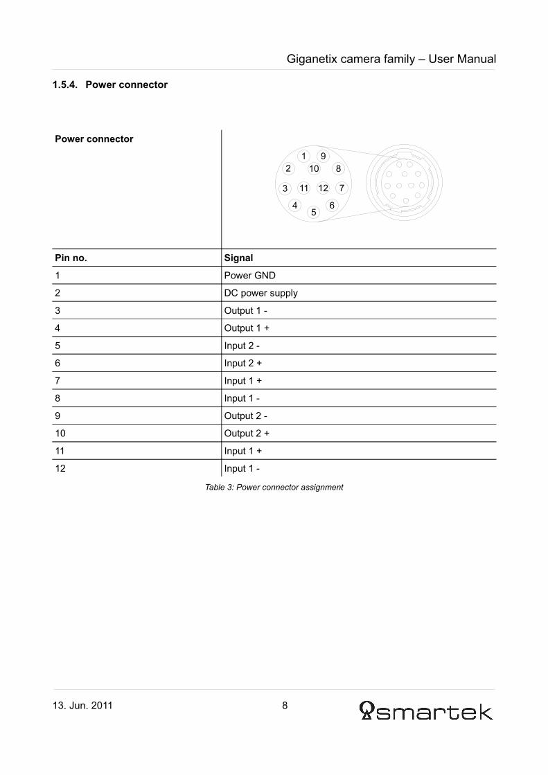
2.2.4. GC3851M / GC3851C
Image sensor Aptina MT9J003
Sensor type CMOS
Sensor resolution (H x W) 3856 x 2764
Optical size 1/2.3"
Pixel size (in μm) 1.67 x 1.67
Analog gain (in dB) 0 ÷ 23.5
Shutter Rolling
Exposure Time 36µs ÷ 10s
Max. frame rate (at full resolution) 7
ADC bit depth 8 bits
Power consumption 2.5W
Weight 90gSpectral Sensitivity
Figure 8: Spectral sensitivity for GC3851 Monochrome
Figure 9: Spectral sensitivity for GC3851 Color
13. Jun. 2011 17

Giganetix camera family – User Manual
2.2.5. GC651M / GC651C
Image sensor Sony ICX618
Sensor type CCD
Sensor resolution (H x W) 659 x 494
Optical size 1/4"
Pixel size (in μm) 5.6 x 5.6
Analog gain (in dB) 0 ÷ 40
Shutter Full frame
Exposure Time 10µs ÷ 10s
Max. frame rate (at full resolution) 120
ADC bit depth 8 – 14 bits
Power consumption 2.3W
Weight 90gSpectral Sensitivity
13. Jun. 2011 18
Figure 10: Spectral sensitivity for GC651 Monochrome
0.0
0.1
0.2
0.3
0.4
0.5
0.6
0.7
0.8
0.9
1.0
400 500 600 700 800 900 1000
Wavelength [nm]
Rela
tive r
esp
on
se
Figure 11: Spectral sensitivity for GC651 ColorWavelength [nm]
1.0
0.8
0.6
0.4
0.2
0400 600450 650500 700550
B
G
R0.9
0.7
0.5
0.3
0.1
Rel
ativ
e re
spon
se

Giganetix camera family – User Manual
2.2.6. GC652M / GC652C
Image sensor Sony ICX424
Sensor type CCD
Sensor resolution (H x W) 659 x 494
Optical size 1/3"
Pixel size (in μm) 7.4 x 7.4
Analog gain (in dB) 0 ÷ 40
Shutter Full frame
Exposure Time 10µs ÷ 10s
Max. frame rate (at full resolution) 90
ADC bit depth 8 – 14 bits
Power consumption 2.6W
Weight 90gSpectral Sensitivity
13. Jun. 2011 19
Figure 12: Spectral sensitivity for GC652 Monochrome
1.0
0.9
0.8
0.7
0.6
0.5
0.4
0.3
0.2
0.1
0400 500 600 700
Wave Length [nm]
800 900 1000
Rel
ativ
e re
spon
se
Figure 13: Spectral sensitivity for GC652 Color
400
1.0
B
G
R
0.9
0.8
0.7
0.6
0.5
0.4
0.3
0.2
0.1
0450 500 550
Wave Length [nm]
600 650 700
Rel
ativ
e re
spon
se

Giganetix camera family – User Manual
2.2.7. GC653M / GC653C
Image sensor Sony ICX414
Sensor type CCD
Sensor resolution (H x W) 659 x 494
Optical size 1/2"
Pixel size (in μm) 9.9 x 9.9
Analog gain (in dB) 0 ÷ 40
Shutter Full frame
Exposure Time 10µs ÷ 10s
Max. frame rate (at full resolution) 90
ADC bit depth 8 – 14 bits
Power consumption 2.6W
Weight 90gSpectral Sensitivity
13. Jun. 2011 20
Figure 14: Spectral sensitivity for GC653 Monochrome
1.0
0.9
0.8
0.7
0.6
0.5
0.4
0.3
0.2
0.1
0400 500 600 700
Wave Length [nm]
800 900 1000
Rel
ativ
e re
spon
se
Figure 15: Spectral sensitivity for GC653 Color
0400 450 500 550 600 650 700
0.2
0.4
0.6
B
G
R0.8
1.0
Wave Length [nm]
Rel
ativ
e re
spon
se

Giganetix camera family – User Manual
2.2.8. GC781M / GC781C
Image sensor Sony ICX415
Sensor type CCD
Sensor resolution (H x W) 782 x 582
Optical size 1/2"
Pixel size (in μm) 8.3 x 8.3
Analog gain (in dB) 0 ÷ 40
Shutter Full frame
Exposure Time 10µs ÷ 10s
Max. frame rate (at full resolution) 64
ADC bit depth 8 – 14 bits
Power consumption 2.6W
Weight 90gSpectral Sensitivity
13. Jun. 2011 21
Figure 16: Spectral sensitivity for GC781 Monochorme
1.0
0.9
0.8
0.7
0.6
0.5
0.4
0.3
0.2
0.1
0400 500 600 700
Wave Length [nm]
800 900 1000
Rel
ativ
e re
spon
se
Figure 17: Spectral sensitivity for GC781 Color
0400 450 500 550 600 650 700
0.2
0.4
0.6
B
G
R0.8
1.0
Wave Length [nm]
Rel
ativ
e re
spon
se

Giganetix camera family – User Manual
2.2.9. GC1031M / GC1031C
Image sensor Sony ICX204
Sensor type CCD
Sensor resolution (H x W) 1034 x 779
Optical size 1/3"
Pixel size (in μm) 4.65 x 4.65
Analog gain (in dB) 0 ÷ 40
Shutter Full frame
Exposure Time 10µs ÷ 10s
Max. frame rate (at full resolution) 30
ADC bit depth 8 – 14 bits
Power consumption 2.2W
Weight 90gSpectral Sensitivity
13. Jun. 2011 22
Figure 18: Spectral sensitivity for GC1031 Monochrome
0
0.2
0.4
0.6
0.8
1
400 500 600 700 800 900 1000
Wave Length [nm]
Rel
ativ
e re
spon
se
Figure 19: Spectral sensitivity for GC1031 Color
0
0.2
0.4
0.6
0.8
1
Wave Length [nm]
400 500 600 700
RG
B
Rel
ativ
e re
spon
se

Giganetix camera family – User Manual
2.2.10. GC1291M / GC1291C
Image sensor Sony ICX445
Sensor type CCD
Sensor resolution (H x W) 1296 x 966
Optical size 1/3"
Pixel size (in μm) 3.75 x 3.75
Analog gain (in dB) 0 ÷ 40
Shutter Full frame
Exposure Time 10µs ÷ 10s
Max. frame rate (at full resolution) 30
ADC bit depth 8 – 14 bits
Power consumption TBD
Weight 90gSpectral Sensitivity
13. Jun. 2011 23
Figure 20: Spectral sensitivity for GC1291 Monochrome
Figure 21: Spectral sensitivity for GC1291 Color

Giganetix camera family – User Manual
2.2.11. GC1391M / GC1391C
Image sensor Sony ICX267
Sensor type CCD
Sensor resolution (H x W) 1392 x 1040
Optical size 1/2"
Pixel size (in μm) 4.65 x 4.65
Analog gain (in dB) 0 ÷ 40
Shutter Full frame
Exposure Time 10µs ÷ 10s
Max. frame rate (at full resolution) 20
ADC bit depth 8 – 14 bits
Power consumption 2.5W
Weight 90gSpectral Sensitivity
13. Jun. 2011 24
Figure 22: Spectral sensitivity for GC1391 Monochrome
1.0
0.8
0.6
0.4
0.2
0400 500 600 700
Wave Length [nm]
800 900 1000
Rel
ativ
e re
spon
se
Figure 23: Spectral sensitivity for GC1391 Color
4000
0.2
0.4
0.6
0.8
1.0
500
Wave Length [nm]
600 700
RG
B
Rel
ativ
e re
spon
se

Giganetix camera family – User Manual
2.2.12. GC1392M / GC1392C
Image sensor Sony ICX285
Sensor type CCD
Sensor resolution (H x W) 1392 x 1040
Optical size 2/3"
Pixel size (in μm) 6.45 x 6.45
Analog gain (in dB) 0 ÷ 40
Shutter Full frame
Exposure Time 10µs ÷ 10s
Max. frame rate (at full resolution) 30
ADC bit depth 8 – 14 bits
Power consumption 2.8W
Weight 90gSpectral Sensitivity
13. Jun. 2011 25
Figure 24: Spectral sensitivity for GC1392 Monochrome
4000
0.2
0.4
0.6
0.8
0.9
0.7
0.5
0.3
0.1
1.0
500 600 700 800 900 1000Wave Length [nm]
Rel
ativ
e re
spon
se
Figure 25: Spectral sensitivity for GC1392 Color
1.0
0.9
0.8
0.7B
G
R
0.6
0.5
0.4
0.3
0.2
0.1
0400 450 500 550
Wave Length [nm]600 650 700
Rel
ativ
e re
spon
se

Giganetix camera family – User Manual
2.2.13. GC1621M / GC1621C
Image sensor Sony ICX274
Sensor type CCD
Sensor resolution (H x W) 1628 x 1236
Optical size 1/1.8"
Pixel size (in μm) 4.4 x 4.4
Analog gain (in dB) 0 ÷ 40
Shutter Full frame
Exposure Time 10µs ÷ 10s
Max. frame rate (at full resolution) 25
ADC bit depth 8 – 14 bits
Power consumption 2.7W
Weight 90gSpectral Sensitivity
13. Jun. 2011 26
Figure 26: Spectral sensitivity for GC1621 MonochromeWave Length [nm]
400 500 600 700 800 900 1000
1.0
0.9
0.8
0.7
0.6
0.5
0.4
0.3
0.2
0.1
0
Rel
ativ
e re
spon
se
Figure 27: Spectral sensitivity for GC1621 Color
1.0
0.8
BGR
0.6
0.4
0.2
0400 450 500 550
Wave Length [nm]
600 650 700
Rel
ativ
e re
spon
se

Giganetix camera family – User Manual
2.2.14. GC2441M / GC2441C
Image sensor Sony ICX625
Sensor type CCD
Sensor resolution (H x W) 2448 x 2050
Optical size 2/3"
Pixel size (in μm) 3.45 x 3.45
Analog gain (in dB) 0 ÷ 40
Shutter Full frame
Exposure Time 10µs ÷ 10s
Max. frame rate (at full resolution) 15
ADC bit depth 8 – 14 bits
Power consumption 3.6W
Weight 90gSpectral Sensitivity
13. Jun. 2011 27
Figure 28: Spectral sensitivity for GC2441 Monochrome
0
0.1
0.2
0.3
0.4
0.5
0.6
0.7
0.8
0.9
1.0
400 500 600 700 800 900 1000Wavelength [nm]
Rel
ativ
e re
spon
se
Figure 29: Spectral sensitivity for GC2441 Color
0
0.1
0.2
0.3
0.4
0.5
0.6
0.7
0.8
0.9
1
400 450 500 550 600 650 700W avelength [nm ]
B
G
R
Relat
ive re
spon
se

Giganetix camera family – User Manual
2.2.15. GC1021M / GC1021C
Image sensor Kodak KAI-01050
Sensor type CCD
Sensor resolution (H x W) 1024 x 1024
Optical size 1/2"
Pixel size (in μm) 5.5 x 5.5
Analog gain (in dB) 0 ÷ 40
Shutter Full frame
Exposure Time 10µs ÷ 10s
Max. frame rate (at full resolution) 60
ADC bit depth 8 – 14 bits
Power consumption TBD
Weight 90gSpectral Sensitivity
13. Jun. 2011 28
Figure 30: Spectral sensitivity for GC1021 Monochrome
0.00
0.10
0.20
0.30
0.40
0.50
0.60
350 400 450 500 550 600 650 700 750 800 850 900 950 1000 1050 1100
Wavelngth (nm)
Rel
ativ
e re
spon
se
Figure 31: Spectral sensitivity for GC1021 Color
0.00
0.10
0.20
0.30
0.40
0.50
0.60
400 450 500 550 600 650 700 750 800 850 900 950 1000 1050 1100
Wavelength (nm)
Rel
ativ
e re
spon
se

Giganetix camera family – User Manual
2.2.16. GC1601M / GC1601C
Image sensor Kodak KAI-02050
Sensor type CCD
Sensor resolution (H x W) 1600 x 1200
Optical size 2/3"
Pixel size (in μm) 5.5 x 5.5
Analog gain (in dB) 0 ÷ 40
Shutter Full frame
Exposure Time 10µs ÷ 10s
Max. frame rate (at full resolution) 30
ADC bit depth 8 – 14 bits
Power consumption TBD
Weight 90gSpectral Sensitivity
13. Jun. 2011 29
Figure 32: Spectral sensitivity for GC1601 Monochrome
0.00
0.10
0.20
0.30
0.40
0.50
0.60
350 400 450 500 550 600 650 700 750 800 850 900 950 1000 1050 1100
Wavelngth (nm)
Rel
ativ
e re
spon
se
Figure 33: Spectral sensitivity for GC1601 Color
0.00
0.10
0.20
0.30
0.40
0.50
0.60
400 450 500 550 600 650 700 750 800 850 900 950 1000 1050 1100
Wavelngth (nm)
Rel
ativ
e re
spon
se

Giganetix camera family – User Manual
2.2.17. GC1921M / GC1921C
Image sensor Kodak KAI-02150
Sensor type CCD
Sensor resolution (H x W) 1920 x 1080
Optical size 2/3"
Pixel size (in μm) 5.5 x 5.5
Analog gain (in dB) 0 ÷ 40
Shutter Full frame
Exposure Time 10µs ÷ 10s
Max. frame rate (at full resolution) 32
ADC bit depth 8 – 14 bits
Power consumption TBD
Weight 90Spectral Sensitivity
13. Jun. 2011 30
Figure 34: Spectral sensitivity for GC1921 Monochrome
0.00
0.10
0.20
0.30
0.40
0.50
0.60
350 400 450 500 550 600 650 700 750 800 850 900 950 1000 1050 1100
Wavelngth (nm)
Rel
ativ
e re
spon
se
Figure 35: Spectral sensitivity for GC1921 Color
0.00
0.10
0.20
0.30
0.40
0.50
0.60
400 450 500 550 600 650 700 750 800 850 900 950 1000 1050 1100
Rel
ativ
e re
spon
se
Wave Length [nm]

Giganetix camera family – User Manual
3. GigEVisionSDK library for Windows3.1. GigEVisionSDK library installation
Before camera can transfer images to PC, GigEVisionSDK library must be installed on PC properly. Follow those steps in order to install the software on your PC.
Step 1: To start the installation run the Smartek GigEVisionSDK library installation.
Step 2: Setup screen appears, click Next.
Step 3: Click Browse to select the destination folder, or just click Next to install the software in the default folder.
13. Jun. 2011 31

Giganetix camera family – User Manual
Step 4: Select which components to install on the drop down menu, or click Next to continue with full installation.
Step 5: Click Browse to select different folder, or click Next to install to the default Start menu folder.
13. Jun. 2011 32

Giganetix camera family – User Manual
Step 6: To install software click Install. Installation will install Smartek Filter Driver and Windows will show a warning messages, click Continue Anyway every time.
Step 7: To complete the installation click Finish and wait for your PC to reboot.
13. Jun. 2011 33

Giganetix camera family – User Manual
3.2. Connecting camera
Now that everything is installed, connect the camera to PC. It can be connected to PC either via Gigabit Ethernet switch or peer to peer with Ethernet cable. Make sure your firewall settings are not blocking communications with camera. If that is the case, firewall must be turned off. In order to turn off the firewall in Windows, find Windows Firewall under Control Panel and turn it off.
3.2.1. Connecting peer to peer with Ethernet cable
Make sure that the Local Area Connection in your Network Connections settings to which the camera is connected is enabled. Now PC will try to acquire network address, in case your IP address is not fixed the following message will appear.
This means that an IP address should be provided manually. To provide IP address manually, right-click on the Local Area Connection to which the camera is connected and press Properties button.
13. Jun. 2011 34

Giganetix camera family – User Manual
Now select Internet Protocol [TCP/IP] and press Properties button.
Enable Use the following IP address and type in, for example the numbers that are shown in the figure below. Note: In order for camera to be connectable, the IP address that is provided manually should be on the same subnet as the camera's IP address.
13. Jun. 2011 35

Giganetix camera family – User Manual
3.2.2. Connecting GigEVisionClient with the camera
Run the GigEVisionClient and click Find Devices icon to start searching for devices.
If no camera has been found check your hardware and software settings. Make sure everything is plugged properly and your firewall settings are not blocking connection to the camera. If you still experience problem please contact Smartek support.
If camera is connected peer to peer with Ethernet cable or via Ethernet switch and no DHCP server is installed, search result can look something like in the picture below. Cameras are shipped in DHCP mode, and in case DHCP server does not exist, camera obtains the IP address using Link-Local Address (LLA) IP configuration protocol. If there is a warning symbol next to the camera model name, the application is unable to connect to the camera because the camera and the PC are on different subnet. Change IP address of the device to be on the same subnet as the IP address in Local Area Connection settings. To change the IP address of the camera click on the Set Ip To Device icon.
13. Jun. 2011 36

Giganetix camera family – User Manual
New window will open. Here you can set the new IP address, subnet mask and gateway. Make sure you don't provide the same IP address to camera as in Local Area Connection settings.
Select the camera that is found and click on the Connect Device icon to connect to the camera.
13. Jun. 2011 37

Giganetix camera family – User Manual
3.3. Filter driver installation
Smartek provides its own filter driver to ensure optimal performance of the digital camera. This driver is compatible with GigE Vision standard. Smartek Filter Driver separates incoming packets containing image data from the other traffic on the network, making the image data flow from the camera to the software more efficient.
If GigEVisionClient is started without the Smartek Filter Driver, the following warning message appears.
There is also a warning message in the top bar “Warning: Smartek Filter Driver not loaded”. Follow this steps to install the Smartek Filter Driver:
Step 1: Open the Local Area Connection in your Network Connections settings to which the camera is connected, and press Properties button.
13. Jun. 2011 38

Giganetix camera family – User Manual
Step 2: Click on the Install button.
Step 3: Select Service and click Add button.
Step 4: Click Have Disk to select a driver to install.
13. Jun. 2011 39

Giganetix camera family – User Manual
Step 5: To select a source folder click Browse.
Step 6: Go to directory where GigEVisionSDK is installed and locate under “\drivers\FilterDriver” files GigEVDrv.inf and GigEVDrv_m.inf. Pick one of them! Note: either one will work.
Step 9: Windows will show a warning messages, click Continue Anyway every time it shows up.
Smartek Filter Driver is installed.
13. Jun. 2011 40

Giganetix camera family – User Manual
4. GigEVisionClient features
General information about the camera selected from the list of discovered devices is displayed under Device Info tab. Under Parameters tab there is a tree of features extracted from GenICam camera description file.
4.1. Acquisition control
The AcquisitionControl section describes all features related to image acquisition, including the trigger and exposure control. It describes the basic model for acquisition and the typical behavior of the device.
13. Jun. 2011 41

Giganetix camera family – User Manual
4.1.1. Acquisition mode
The AcquisitionMode property controls the acquisition mode of the device. It defines the number of frames captured during the acquisition and the way the acquisition stops. It can take any of the following values:
• Continuous – frames are captured continuously until stopped with the AcquisitionStop command
• SingleFrame – camera captures only one frame.
• MultiFrame – camera captures a specific number of frames (number of frames is set under the AcquisitionFrameCount).
In order for the camera to run in “continuous frame” or “free run” mode, in which camera acquires and transfers images at maximum supported frame rate, AcquisitionMode must be set to Continuous and TriggerMode must be set to Off. When in SingleFrame or MultiFrame mode, camera acquires certain number of frames and then acquisition is stopped.
4.1.2. Trigger mode
TriggerMode activates/deactivates trigger operation. It can take any of the following values:
• On – enables trigger operation
• Off – disables trigger operation
Once again, setting the TriggerMode property to Off and the AcquisitionMode property to Continuous places the camera into “free run” mode.
4.1.3. Trigger source
TriggerSource specifies the internal signal or physical input line to use as the trigger source. The selected trigger must have its TriggerMode set to On. TriggerSource can take any of the following values:
• Software – specifies that the trigger source will be generated by software using the TriggerSoftware command.
• Line1, Line2 – specifies which physical line (or pin) and associated I/O control block to use as external source for the trigger signal.
13. Jun. 2011 42

Giganetix camera family – User Manual
4.1.4. Trigger activation
TriggerActivation specifies the activation mode of the trigger. TriggerActivation can take any of the following values:
• RisingEdge – specifies that the trigger is considered valid on the rising edge of the source signal.
• FallingEdge – specifies that the trigger is considered valid on the falling edge of the source signal.
4.1.5. Exposure
Exposure feature defines the sensor integration time. It is a time the image sensor is converting incoming light into electronic charge in pixels before transferring the frame off the chip. Exposure duration can be set and is expressed in microseconds. See 3.4. Sensor information and technical specification (all models separate) for definition of default exposure and exposure range for each image sensor.
ExposureMode feature is used to set the operation mode of the Exposure. The default value is Timed:
• Timed – enables exposure. The exposure duration time is set by using the ExposureTime.
Example of different ExposureTime settings. In the left picture ExposureTime is set to 10000 µs, and in the right it is set to 22000 µs.
13. Jun. 2011 43
Figure 36: Different exposure time setting

Giganetix camera family – User Manual
4.1.6. Test your camera
Set AcquisitionMode to Continuous(1), TriggerMode to Off(2) and click Start(3). The image should appear on the screen.
Note: if the image display is all black and the Snap FPS(4) value is above zero, than try opening the lens iris. If you are still experiencing problem, please contact Smartek support.
13. Jun. 2011 44

Giganetix camera family – User Manual
4.2. External trigger
External trigger is used when the camera needs to be synchronized to external trigger event. The camera can be triggered on the rising or the falling edge of the input trigger signal. The minimum width of the external trigger signal is defined by the trigger debouncer time property.
4.2.1. Trigger latency
Trigger latency is time expressed in microseconds which shows how long it takes for camera to detect an external trigger input. Trigger latency can't be modified. Please compare this important feature with other manufacturers.
4.2.2. Trigger delay
Trigger delay is a delay from input trigger to exposure start and is expressed in µs. Trigger delay can be set.
4.2.3. Trigger edge
• Rising edge – exposure starts on the rising edge of the trigger.
• Falling edge – exposure starts on the falling edge of the trigger.
13. Jun. 2011 45Figure 38: Exposure with a falling edge of the trigger
External trigger signal
External trigger signal period
Exposure
Figure 37: Exposure with rising edge of the trigger
External trigger signal
External trigger signal period
Exposure

Giganetix camera family – User Manual
4.2.4. Trigger debouncer
Trigger debouncer time defines minimum time interval that input signal must remain active in order to be recognized as valid trigger input signal. Trigger debouncer is used to prevent possible unwanted trigger events. It eliminates short noises that could easily be interpreted as trigger signals. The function of the trigger debouncer is shown in the figure below: two glitches are ignored by the debouncer because the width of those signals is shorter than the debouncer time value, while the third signal is accepted as valid trigger signal because it's width is longer than the debouncer time limit. TriggerDebouncerTime feature is used to set trigger debouncer time expressed in µs. Trigger debouncer time effectively increases delay time between external trigger signal and internal trigger signal used to start the exposure, so it should be set large enough so as to filter unwanted glitches to trigger the camera and small enough to keep the delay as small as possible.
13. Jun. 2011 46
Figure 39: Trigger debouncer function
Debouncer limit
Delay
Unfiltered arriving signals
Debouncer
Internal trigger signal

Giganetix camera family – User Manual
13. Jun. 2011 47
Figure 40: Complete process of image acquisition
Debouncer value
Unfiltered arriving signals
Debouncer
Internal trigger signal
Trigger latency (fixed value)
Latency
Trigger delay (can be set to zero)
Delay
Exposure
Exposure
Debouncer value

Giganetix camera family – User Manual
4.3. Parallel exposure and sensor readout
The image acquisition process on the camera includes two distinct parts. The first part is the exposure of the pixels in the image sensor. Once exposure is complete, the second part of the process readout of the pixel values from the sensor takes place. As you can see, running the camera with readout and exposure overlapped can allow higher acquisition frame rates because the camera is performing two processes at once.
4.4. Acquisition frame rate
When camera is configured in “continuous frame” or “free run” mode, AcquisitionMode is set to Continuous and TriggerMode is set to Off, it continuously acquires and transmits images at maximum supported frame rate. Using AcquisitionFrameRate feature it is possible to decrease the number of frames camera acquires and transmits in “free run” mode, which, consequently, lowers the Ethernet bandwidth needed by the camera. This is useful in situations where Ethernet bandwidth is limited, like connecting several cameras to the PC which can acquire images at faster speed than is needed by application. For example, if the camera is transferring images at 70 MB/s (2Mpix camera at 35 fps), it is not possible to connect two of them to a single port PC network card because of the Ethernet bandwidth limitation. Setting acquisition frame rate to 20 fps, camera is using only 40 MB/s so there is enough bandwidth left for the second camera to transfer images.
Setting AcquisitionFrameRate property to zero effectively disables the feature allowing the camera to acquire and transfer images at maximum frame rate.
13. Jun. 2011 48
Figure 41: Parallel exposure and readout
Exposure ReadoutImage acquisition N
Exposure ReadoutImage acquisition N + 1
Exposure ReadoutImage acquisition N + 2
Exposure ReadoutImage acquisition N + 3
Time

Giganetix camera family – User Manual
4.5. Inter packet delay
This feature is used when connecting multiple cameras to one PC. If multiple cameras are connected to PC and inter packet delay feature isn't used, excessive collision between packets may occur and data may be lost. In order to avoid that, delay between packets can be defined. This feature ensures that none of data is lost and all packets are transferred safely to their destination.
13. Jun. 2011 49
Figure 42: Without inter packet delay
Packet n Packet 3 Packet 2
Packet 3 Packet 3Packet n Packet 2
Packet 1Packet 1
Camera 1
Camera 2
Collision
Packets sending flow Packets receiving flow
Figure 43: Using inter packet delay
Packet n Delay Packet 2
Delay Packet 2 Delay
Packet 1 Packet 1
Camera 1
Camera 2
Packets sending flow Packets receiving flow

Giganetix camera family – User Manual
4.5.1. Setting inter packet delay
In TransportLayerControl section there are features GevSCPSPacketSize and GevSCPD. GevSCPD feature represents inter packet delay and is expressed in microseconds. This value can range from 0 to 1000 μs. Inter packet delay should be set according to number of cameras connected to certain PC and packet size, but care must be taken not to decrease acquisition frame rate. Default inter packet delay on the camera is defined as (packet size)/100 μs, meaning that default inter packet delay for 1500 byte packets is 15 μs.
GevSCPSPacketSize feature represents the size of packets and is expressed in bytes. When GigEVisionClient connects to camera, it tests for maximum available packet size. Default camera packet size is 1500 bytes, but it can be larger if network hardware supports jumbo frames.
Assuming packet size is 1500 bytes (actual Ethernet packet size including inter-frame gap, preamble, header and CRC on the wire is 1538 bytes), maximum of 81274 packets are sent every second via Ethernet interface, which means that time required to transfer one packet is 12,3 μs. Delay should be a bit longer than time required to transfer one packet, in order to ensure that packets from second camera will fit in the vacant time slot. On the other hand, if the camera is producing 60000 packets per second (50 frames per second, 1200 packets per frame), total transfer time must not exceed 16,67 μs if frame rate is to be preserved.
Example: Three cameras are connected to one PC, and are sending 1500 byte packets each. Delay should be such that packets from all three cameras are serialized to PC NIC interface. Setting inter packet delay to 30μs will ensure that packets from other two cameras will fit in the gap between two consecutive packets.
13. Jun. 2011 50
Figure 45: Example: inter packet delay (three cameras)
Delay Packet 2
Delay Packet 2 Delay Packet 1 Packet 1
Camera 1
Camera 2
Packet 2 Delay
Camera 3
Packet 3
Delay
Packet 1
Arriving packet flow
Figure 44: Packet size and inter packet delay

Giganetix camera family – User Manual
4.6. Area Of Interest (AOI)
Area Of Interest feature allows you to select a specific part of the image sensor area. In other words, only the pixels from the area defined by your settings will be transmitted to PC. The parameters that can be set:
• Vertical pixel offset
• Vertical pixel count
• Horizontal pixel offset
• Horizontal pixel count
To increase frame rate at CCD cameras, vertical image size can be decreased. Decreasing horizontal image size does not increase frame rate at CCD cameras. For CMOS cameras decreasing vertical or horizontal image increases frame rate. It can be used to minimize data exchange.
13. Jun. 2011 51
Figure 46: Area Of Interest
Height
Width
OffsetY
OffsetX
Maximum width
Maximumheight

Giganetix camera family – User Manual
4.6.1. Setting Area Of Interest
Area Of Interest is defined in the ImageFormatControl section.
Here is an example of setting the Area Of Interest.
Values for image below:
Width 1392,
Height 1040,
OffsetX 0,
OffsetY 0.
Values for image below:
Width 879,
Height 535,
OffsetX 0,
OffsetY 0.
Values for image below:
Width 879,
Height 535,
OffsetX 255,
OffsetY 380.
13. Jun. 2011 52
Figure 47: Settings for different Area Of Interest

Giganetix camera family – User Manual
4.7. Analog control
4.7.1. Gain
Gain property controls the selected gain as an absolute physical value. This is an amplification factor applied to the video signal. The unit and values of this feature are specific to the device and must be defined in the XML device description file. The camera’s gain is expressed in decibels. CCD signal is amplified and digitized in analog-digital converter. By setting the gain we are adjusting camera's gray values. Gain also increases image sensor's analog noise. Default gain and gain range for each image sensor is defined in the section 3.4 Sensor information and technical specification (all models separate)
4.7.2. Black level
BlackLevel property controls the analog black level as an absolute physical value. This represents a DC offset applied to the video signal. The unit and values of this feature are specific to the device and must be defined in the XML device description file. Black level is an additive to camera's analog video signal before digitization. Black level offset increases or decreases image brightness. It's expressed in percentage (full scale).
Here are examples of setting the Gain. In the left image Gain is set to 19, and in the right is set to 14.
13. Jun. 2011 53
Figure 48: Different gain set

Giganetix camera family – User Manual
4.8. IR filter and IR-cut filter (optional)
Infrared filters are long-pass filters that block the visible light and pass IR light. They are characterized by their cut-on wavelength, typically the wavelength at which the transmission is 50% of the maximum. These filters use absorptive glass, that is robust, cost-effective and insensitive to angle of incidence.
The IR-cut filter is a short pass filter that blocks infrared light and transmits the visible, also based on an absorptive glass.
13. Jun. 2011 54
Figure 49: Infrared filter specification
Figure 50: IR Cut filter specification

Giganetix camera family – User Manual
4.9. Firmware update
To update the camera firmware follow these steps:
Under Control menu press Firmware Update option.
Click on the Browse button to select a firmware to install.
Find and open a firmware to install. After selecting and opening firmware, program will run a compatibility test between the device and firmware. If the selected firmware is compatible “PASSED” is indicated in text window. Upload new firmware to device button will become available, click on that button.
13. Jun. 2011 55

Giganetix camera family – User Manual
The device calculates Cyclic Redundancy Check (CRC) of uploaded firmware. If the CRC is OK, firmware is written to device's memory. This process can take a couple of minutes. When updating of new firmware finishes, simply close the dialog box. The below image shows successful firmware update.
In case of any errors, please repeat the update process.
13. Jun. 2011 56

Giganetix camera family – User Manual
5. FAQ - Frequently asked questionsQ. What image sensors are used on Giganetix cameras?
A. Our Giganetix cameras use CMOS image sensors from Aptina and CCD image sensors from Sony and Kodak.
Q. What is the camera architecture?
A. Giganetix camera uses Altera Cyclone III FPGA.
Q. What is the maximum Ethernet cable length that can be used with Giganetix camera?
A. The maximum Ethernet cable length is 100m.
Q. How do you connect to Giganetix camera from PC?
A. Giganetix camera comes with GigE Vision compliant client application (to display images) and IP filter driver which filters GigE Vision stream channel data (images) from network traffic. This way CPU utilization is reduced to minimum so there is enough CPU power left for image processing.
Q. What is the maximum frame rate of Giganetix camera?
A. Maximum frame rate of camera is defined as maximum frame rate at full resolution and is different for every camera model (if image sensor area is bigger, maximum frame rate is smaller, for same pixel clock frequency). User can choose to increase frame rate by reducing image AOI (area of interest).
Q. What is “partial scan”?
A. Frame rate of camera (number of images camera captures per second) depends on AOI (image width x image height) and pixel frequency (if exposure time is small enough). When higher frame rate is needed, user can choose to reduce number of rows to scan by dropping lines from start or end of image (image is only partially scanned). This effectively reduces AOI and thus increases frame rate.
Q. What are the minimum and maximum exposure times for cameras?
A. The minimum and maximum exposure times for cameras are defined in accompanied documentation.
Q. How to connect more then one camera to PC?
A. To connect more cameras to PC use a Gigabit Ethernet switch or PC NIC with multiple ports.
Q. Why are there noise lines in the GigEVisionClient?
A. The noise lines represent the loss of data packets. Please check your NIC, Ethernet switch and network settings. Use GevSCPD property to increase inter packet delay.
13. Jun. 2011 57
Giganetix camera family – User Manual
6. CE Conformity declarationWe,
Smartek d.o.o.
Ziskovec 141, HR-40000 Cakovec, Croatia
Contact Person: Mr. Damir Dolar
Email: [email protected]
Hereby declare that:
Product: Digital Gigabit Ethernet Camera
Type Family: Giganetix
Type: GC1281M, GC2041C, GC2591M, GC2591C, GC3851M, GC3851C
GC651M, GC651C, GC652M, GC652C, GC653M, GC653C,
GC781M, GC781C, GC1031M, GC1031C, GC1291M, GC1291C
GC1391M, GC1391C, GC1392M, GC1392C, GC1621M, GC1621C,
GC2441M, GC2441C, GC1021M, GC1021C, GC1601M, GC1601C
GC1921M, GC1921C
Is in compliance with the essential requirements and other relevant provisions of the following EC directives.
Reference No. Title
89/336/EEC, 92/31/EEC Electromagnetic Compatibility (EMC directive)
Following standards or normative documents:
EN 55022:1994 Class A + A1:1995 + A2:1997,
EN 61326:1997 Class A + A1:1998 + A2:2001 + A3:2003,
EN 55024:1998 + A1:2001 + A2:2003
The product specified above was tested conforming to the applicable Rules under the most accurate measurement standards possible, and that all the necessary steps have been taken and are in force to assure that production units of the same product will continue comply with the requirements.
13. Jun. 2011 58
13. Jun. 2011
Damir DolarDipl. Ing. Hardware EngineerSmartek d.o.o.

Giganetix camera family – User Manual
7. Smartek Information
Published by:
Smartek d.o.o.
Ziskovec 141,
HR-40000 Cakovec
Croatia
www.smartek.hr
Email: [email protected]
Tel: ++385 40 86 57 32
Fax : ++385 40 86 57 31
Copyright © 2011 by Smartek d.o.o. All rights reserved.
For further information please contact our sales partners.
13. Jun. 2011 59


![Section [11] External Background - ClassNK · Background Document SECTION 11 – GENERAL REQUIREMENTS ... 1.4.4 Structural continuity 1.4.4.a The text of 1.4.4.1 – 1.4.4.4 is taken](https://img.pdfslide.us/doc/110x75/5b058bf87f8b9a93418b7f02/section-11-external-background-classnk-document-section-11-general-requirements.jpg)