Embed Size (px)
Citation preview

USER MANUAL
DriveMaster Ultra 3.5, 5, 7.5, 10 & 20
ELECTRIC PROPULSION SYSTEMS
MASTERVOLT Snijdersbergweg 93, 1105 AN Amsterdam The Netherlands Tel.: +31-20-3422100 Fax.: +31-20-6971006 www.mastervolt.com
Copyright © 2011 Mastervolt, v 0.5 March 2011

CONTENTS
2 March 2011 / DriveMaster Ultra / EN
CONTENTS
1 GENERAL INFORMATION .................................................................................................................................................. 4 1.1 USE OF THIS MANUAL ........................................................................................................................................ 4 1.2 VALIDITY OF THIS MANUAL ............................................................................................................................... 4 1.3 GUARANTEE SPECIFICATION ........................................................................................................................... 4 1.4 LIABILITY .............................................................................................................................................................. 4
2 SAFETY GUIDELINES AND MEASURES .......................................................................................................................... 5 2.1 WARNINGS AND SYMBOLS ................................................................................................................................ 5 2.2 USE FOR INTENDED PURPOSE ........................................................................................................................ 5 2.3 GENERAL SAFETY AND INSTALLATION PRECAUTIONS ............................................................................... 5 2.4 WARNING REGARDING LIFE SUPPORT APPLICATIONS ............................................................................... 5 2.5 WARNING REGARDING THE USE OF BATTERIES .......................................................................................... 6
3 HOW IT WORKS .................................................................................................................................................................. 7 3.1 DRIVEMASTER ULTRA SYSTEM ........................................................................................................................ 7 3.2 COMPONENTS ..................................................................................................................................................... 7
3.2.1 MOTOR CONTROLLER AND MOTOR ............................................................................................... 7 3.2.2 DISPLAY, JOYSTICK AND MOTOR SWITCH .................................................................................... 8 3.2.3 MAIN SWITCH AND FUSE .................................................................................................................. 8
4 OPERATION ......................................................................................................................................................................... 9 4.1 SWITCHING ON AND OFF ................................................................................................................................... 9 4.2 USE OF THE DISPLAY ......................................................................................................................................... 9 4.3 USE OF THE JOYSTICK .................................................................................................................................... 10 4.4 DEPARTURE ....................................................................................................................................................... 10 4.5 ARRIVAL ............................................................................................................................................................. 10
5 INSTALLATION .................................................................................................................................................................. 11 5.1 GENERAL CONSIDERATIONS FOR A SILENT PROPELLER SHAFT SYSTEM ............................................ 11 5.2 COMPONENTS ................................................................................................................................................... 11 5.3 MOTOR ................................................................................................................................................................ 11 5.4 A-FLEX COUPLING ............................................................................................................................................ 12
5.4.1 HOMOKINETIC JOINT ...................................................................................................................... 12 5.4.2 THRUST BEARING ............................................................................................................................ 13
5.5 MOTOR CONTROLLER...................................................................................................................................... 14 5.6 DISPLAY .............................................................................................................................................................. 15 5.7 JOYSTICK ........................................................................................................................................................... 15 5.8 WIRING ................................................................................................................................................................ 15
5.8.1 MOTOR CONTROLLER CONNECTIONS ........................................................................................ 17 5.8.2 CONNECTION OF MOTOR CABLES ............................................................................................... 17 5.8.3 CONNECTION OF SIGNAL CABLES ............................................................................................... 18 5.8.4 CONNECTION OF POWER CABLES ............................................................................................... 18
5.9 CALIBRATION ..................................................................................................................................................... 19 5.10 COMMISSIONING ............................................................................................................................................... 19
6 MAINTENANCE.................................................................................................................................................................. 20 6.1 PREVENTIVE MAINTENANCE .......................................................................................................................... 20 6.2 MAINTENANCE................................................................................................................................................... 20
7 TROUBLE SHOOTING ...................................................................................................................................................... 21
8 TECHNICAL DATA ............................................................................................................................................................ 22 8.1 TECHNICAL SPECIFICATIONS ......................................................................................................................... 22

CONTENTS
EN / DriveMaster Ultra / March 2011 3
8.2 DIMENSIONS ...................................................................................................................................................... 23 8.2.1 DISPLAY ............................................................................................................................................ 23 8.2.2 MOTOR CONTROLLER .................................................................................................................... 24 8.2.3 ASYNCHRONOUS MOTOR .............................................................................................................. 27
9 ORDERING INFORMATION .............................................................................................................................................. 32

GENERAL INFORMATION
4 March 2011 / DriveMaster Ultra / EN
1 GENERAL INFORMATION 1.1 USE OF THIS MANUAL Copyright © 2010 Mastervolt. All rights reserved. Reproduction, transfer, distribution or storage of part or all of the contents in this document in any form without the prior written permission of Mastervolt is prohibited. This manual contains important safety and operating instructions for the safe and effective operation of the DriveMaster Ultra series. Also maintenance instructions and possible correction of minor malfunctions of the DriveMaster Ultra series are included. It is therefore obligatory that every person who works on or with a DriveMaster Ultra is completely familiar with the contents of this manual, and that he/she carefully follows the instructions and important safety instructions contained herein. Installation and maintenance of a DriveMaster system may only be performed by qualified and authorized personnel, in accordance with regulations and in compliance with the mentioned safety measures. Keep this manual in a safe place! 1.2 VALIDITY OF THIS MANUAL All of the specifications, provisions and instructions contained in this manual apply solely to standard versions of the DriveMaster Ultra series delivered by Mastervolt. For other models see other manuals available on our website: www.mastervolt.com. 1.3 GUARANTEE SPECIFICATION Mastervolt guarantees that this unit has been built according to the legally applicable standards and specifications. Should work take place, which is not in accordance with the guidelines, instructions and specifications contained in this user manual, then damage may occur and/or the unit may no longer meet its specifications. All of these matters may mean that the guarantee becomes void. The guarantee is limited to the costs of repair and/or replacement of the product. Costs for installation labor or shipping of the defective parts are not covered by this guarantee. During production and before delivery, all equipment is tested and inspected. The standard warranty period is two years after purchase.
1.4 LIABILITY Mastervolt can accept no liability for: Consequential damage due to the use of a
DriveMaster Ultra system; Possible errors in the manuals and their
consequences.

SAFETY GUIDELINES AND MEASURES
EN / DriveMaster Ultra / March 2011 5
2 SAFETY GUIDELINES AND MEASURES 2.1 WARNINGS AND SYMBOLS The following warning, caution and attention symbols are used in this manual.
WARNING! A WARNING refers to possible injury to persons if the user does not (carefully) follow the procedures.
CAUTION! A CAUTION sign refers to possible significant damage to the equipment if the user does not (carefully) follow the procedures, restrictions and rules.
ATTENTION! An ATTENTION sign refers to procedures, circumstances, etc. which deserve extra attention.
2.2 USE FOR INTENDED PURPOSE A DriveMaster Ultra system may only be used for ship propulsion and according to the installation, operation and maintenance instructions of this manual. 2.3 GENERAL SAFETY AND INSTALLATION
PRECAUTIONS Read this manual thoroughly before installing and/or
using the electric components; Follow the assembly instructions carefully; Only work with the controller when the drive is
switched off. It is important to switch off the power supply of the electric drive with the main switch. Remove the key and keep it with you so that nobody else can turn it back on;
Be aware of your speed. The speed is often underestimated because of the lack of sound;
Be alert to your surroundings; silent sail means that others can hardly hear you.
2.4 WARNING REGARDING LIFE SUPPORT APPLICATIONS
The DriveMaster Ultra is not intended for use in any medical equipment that is intended for use as a component of any life support system unless a specific written agreement pertaining to such intended use is executed between the manufacturer and Mastervolt. Such agreement will require the equipment manufacturer either to contract additional reliability testing of the DriveMaster Ultra and/or to commit to undertake such testing as a part of the manufacturing process. In addition, the manufacturer must agree to indemnify and not hold Mastervolt responsible for any claims arising from the use of the DriveMaster Ultra in life support equipment.

SAFETY GUIDELINES AND MEASURES
6 March 2011 / DriveMaster Ultra / EN
2.5 WARNING REGARDING THE USE OF BATTERIES
Pay attention to the following when working with batteries: Someone should be within hearing range or close
enough to come to your aid when you work near a lead-acid (AGM or gel) or Li-Ion battery;
Have plenty of fresh water and soap nearby in case battery acid contacts skin, clothing or eyes;
Wear complete eye protection and clothing protection. Avoid touching eyes while working near a battery;
If battery acid contacts skin or clothing, wash immediately with soap and water. If acid enters the eye, immediately flood the eye with cold running water for at least 10 minutes and get medical attention immediately;
NEVER smoke or allow a spark or flame in the vicinity of a battery or engine;
Do not short circuit batteries, as this may result in an explosion and fire hazard! Take extra care to reduce the risk of dropping a metal tool onto a battery. It might spark or short-circuit the battery or other electrical part and it may cause an explosion;
Remove personal metal items such as rings, bracelets, necklaces, and watches when working with a battery. A battery can produce a short-circuit current that is high enough to weld a ring or anything like it, to metal, causing a severe burn;
NEVER charge a frozen battery; Excessive battery discharge and/or high charging
voltages can cause serious damage to batteries. Do not exceed the recommended limits of the discharge level of your batteries;
If it is necessary to remove a battery, always remove the grounded terminal from the battery first. Make sure all accessories are off, so as not to cause an arc;
Be sure that the area around the battery is well ventilated while the battery is being charged. Refer to the recommendations of the battery manufacturer;
Batteries are heavy! It may become a projectile if it is involved in an accident! Ensure adequate and secure mounting and always use suitable handling equipment for transportation.

HOW IT WORKS
EN / DriveMaster Ultra / March 2011 7
3 HOW IT WORKS
Figure 1: System block diagram 3.1 DRIVEMASTER ULTRA SYSTEM The diagram of Figure 1 gives a simplified view of a DriveMaster Ultra system. The main parts of the system are the battery and controller, supplying the motor with energy, and the motor with propeller, providing the thrust for the propulsion. The system is operated by the joystick and the motor switch with a key. The joystick sends speed and direction information to the controller which transmits the right amount of power to the motor. The motor switch is used to turn the system on and off and select its operating mode. Information about battery voltage, remaining power, thrust power and possible malfunctions is shown on the display. Furthermore, there is a fuse for protection and a main switch for powering on and off. The motor controller is the key element in the system. It manages operation, protection and information. 3.2 COMPONENTS A DriveMaster Ultra comes with the following components: Motor controller Asynchronous motor with premounted flange on shaft Display Motor switch (with key) Main switch Main fuse and main fuse holder Connection cable (display, joystick and contact key)
and battery connectors Please check the contents of the box before you start with the installation. If any of the items is missing, please contact your supplier.
3.2.1 MOTOR CONTROLLER AND MOTOR The DriveMaster Ultra motor controller serves to control the speed of the asynchronous (induction) motor that is specifically developed for low voltage operation. The microprocessor control allows the motor to be completely and accurately controlled and monitored. The controller software allows various properties of the drive to be set. Some of these properties are: Maximum speed Maximum modus / economy modus Maximum power Acceleration Deceleration Boost and boost time Joystick performance Battery management
These properties and many others have already been set by Mastervolt. They can be adjusted to specific wishes by a Mastervolt dealer.
JOYSTICK DISPLAY
CONTROLLER MOTOR PROPELLER
INCLUDED IN THE DRIVEMASTER 3.5 SYSTEM
MAIN FUSE
BATTERY
MAIN SWITCH
MOTOR
KEY
SWITCH

HOW IT WORKS
8 March 2011 / DriveMaster Ultra / EN
3.2.2 DISPLAY, JOYSTICK AND MOTOR SWITCH The control cable connects the motor controller with the operating instruments: the display, the joystick and the motor switch. The joystick is not included in the system and needs to be ordered separately. Various versions are available (see chapter 9).
3.2.3 MAIN SWITCH AND FUSE The main switch is mounted between the fuse and the motor controller in order to disconnect the batteries during emergencies and maintenance.
OPERATION
EN / DriveMaster Ultra / March 2011 9
4 OPERATION 4.1 SWITCHING ON AND OFF The motor is switched on by turning the key clockwise in the motor switch. The motor switch has three positions: "off", "maximum" and "economy". Two power programs are available: Maximum: the full power of the motor is available; Economy: the maximum speed of the motor is
reduced, as well as the maximum power.
WARNING! It is possible to switch between the two power programs while the motor is running. Be aware that switching from “Economy” to “Maximum” will increase the speed of the motor and that of the boat instantly.
It is possible to remove the key in the "economy" (reduced power) position for safety reasons. The system is switched off by turning the key counter-clockwise to the “off” position. 4.2 USE OF THE DISPLAY After switching on the motor, the display lights up.
1 2 3
4
679
5
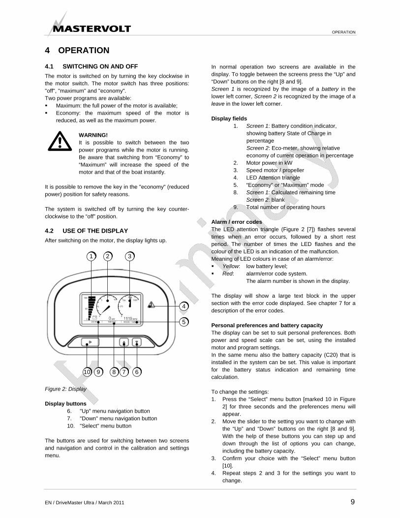
810 Figure 2: Display Display buttons
6. "Up" menu navigation button 7. "Down" menu navigation button 10. "Select" menu button
The buttons are used for switching between two screens and navigation and control in the calibration and settings menu.
In normal operation two screens are available in the display. To toggle between the screens press the “Up” and “Down” buttons on the right [8 and 9]. Screen 1 is recognized by the image of a battery in the lower left corner, Screen 2 is recognized by the image of a leave in the lower left corner. Display fields
1. Screen 1: Battery condition indicator, showing battery State of Charge in percentage Screen 2: Eco-meter, showing relative economy of current operation in percentage
2. Motor power in kW 3. Speed motor / propeller 4. LED Attention triangle 5. “Economy” or “Maximum” mode 8. Screen 1: Calculated remaining time Screen 2: blank 9. Total number of operating hours
Alarm / error codes The LED attention triangle (Figure 2 [7]) flashes several times when an error occurs, followed by a short rest period. The number of times the LED flashes and the colour of the LED is an indication of the malfunction. Meaning of LED colours in case of an alarm/error: Yellow: low battery level; Red: alarm/error code system.
The alarm number is shown in the display. The display will show a large text block in the upper section with the error code displayed. See chapter 7 for a description of the error codes. Personal preferences and battery capacity The display can be set to suit personal preferences. Both power and speed scale can be set, using the installed motor and program settings. In the same menu also the battery capacity (C20) that is installed in the system can be set. This value is important for the battery status indication and remaining time calculation. To change the settings: 1. Press the “Select” menu button [marked 10 in Figure
2] for three seconds and the preferences menu will appear.
2. Move the slider to the setting you want to change with the “Up” and “Down” buttons on the right [8 and 9]. With the help of these buttons you can step up and down through the list of options you can change, including the battery capacity.
3. Confirm your choice with the “Select” menu button [10].
4. Repeat steps 2 and 3 for the settings you want to change.

OPERATION
10 March 2011 / DriveMaster Ultra / EN
5. Go to “Exit” to leave the settings menu and confirm with the “Select” menu button [10].
6. Press the “Select” menu button [10] for three seconds to leave the menu. The settings have now been changed.
4.3 USE OF THE JOYSTICK The desired power and speed can be adjusted in forward and backward direction with the joystick, by turning it over the full stroke. This happens without intermediate steps. Figure 3 shows the joystick with default forward (clock-wise) and backward (counter clockwise) operation.
Figure 3: Joystick Refer to the ordering information in chapter 9 for available types. 4.4 OTHER OPERATION FUNCTIONS During normal operation the following functions exist and operate autonomously: 1. Boost function:
To accommodate fast maneuvering, a DriveMaster
Ultra system is able to deliver an additional amount of power for a limited amount of time when changing direction by the throttle.
2. Sleep function: Whenever the throttle is in neutral position for over 60 minutes (standard setting), the DriveMaster Ultra will switch to Sleep mode limiting the amount of power use. To switch back to normal operation switch the system off and on by using the motor switch.
4.5 DEPARTURE Before departure, always check the system for correct functioning. Follow these steps: 3. Disconnect the shore connection. 4. Turn the main switch on. 5. Put the joystick in the neutral position. 6. Turn the motor switch on. 7. Check the battery condition. 8. Choose the power program (maximum or economy). 9. Check system forward and backward. 4.6 ARRIVAL Follow these steps after arrival: 1. Put the joystick in the neutral position. 2. Check the battery condition. 3. Turn the motor switch off. 4. Turn the main switch off. 5. Connect the shore connection and make sure it works
properly. 6. Reload the batteries after arrival.

INSTALLATION
EN / DriveMaster Ultra / March 2011 11
5 INSTALLATION During installation and commissioning of a DriveMaster Ultra system, the safety instructions of chapter 2 must be followed.
CAUTION! The complete set is fully tested and provided with the correct base settings in the factory, which means that the proper motor controller always needs to be combined with the proper motor. Check the serial number of the motor controller and that of the motor; they must be identical.
Notes For a proper installation of the DriveMaster Ultra, take note of the following: Check the propeller shaft for straightness; Use a balanced propeller that is suitable for the
system on the boat; Provide the balanced propeller if necessary with a so
called “anti-singing edge”; Pay attention to the position of the propeller in the
shaft and the relative position of the rudder; A number of optional items to make installation easier can be found in chapter 9. 5.1 GENERAL CONSIDERATIONS FOR A
SILENT PROPELLER SHAFT SYSTEM
Figure 4: Propeller system
Before installing the propeller shaft system, the following three points must be considered to make the (electric) drive real quiet. The points are listed in order of importance. Inflow of the water from the propeller.
For example, a propeller with a 2.4 kW drive moves about 280 liter water per second. The water inflow should be disrupted at a minimum and the water should flow horizontally through the propeller. If the boat has a keel from which the propeller protrudes, then the keel must be narrowed above and below the propeller shaft to get the inflow to the propeller as smooth as possible. See Figure 4. The view of the keel shows the difference between a straight keel and a keel that is narrowed.
There must be enough space (at least 15% of the propeller diameter) between the propeller and the hull. The same applies when a heel is mounted that supports the rudder. When designing the heel, it is important that the inflow of water is not disrupted. A curved piece of flat steel can cause tremendous turbulence in the water causing noise and loss of efficiency.
There must be sufficient space between the propeller and the rudder. It is an advantage that the rudder is drop shaped en is not made out of a flat plate. This drop shaped design is also called a NACA profile.
5.2 COMPONENTS See the block diagram in chapter 3 and the wiring diagram in section 5.8. 5.3 MOTOR A DriveMaster Ultra electric drive system is quiet and has little vibration when installed correctly. In order to achieve this, pay close attention to the placement of the motor and the entire propeller shaft system.

INSTALLATION
12 March 2011 / DriveMaster Ultra / EN
Figure 5: Mounting the motor The motor must be mounted directly on an existing foundation or by using the optional support bracket. The motor must be fixed by using four bolts, as shown in Figure 5.
CAUTION! In a propulsion system using a propeller, a thrust bearing must always be present to transmit the large forces generated by the motor to the hull.
The motor can be installed with or without a homokinetic coupling. If no homokinetic coupling is used, the motor has to be 100% in-line. In combination with a homokinetic coupling, the motor must be placed slightly out of line. This is to guarantee the lubrication of the homokinetic joint. During installation of the motor pay attention to the following: Check that all bolts are tightened after positioning the
motor and propeller shaft system; Make sure that the motor is well protected and
prepare for unforeseen circumstances like leakage. Suggestion: place a bilge pump;
Clockwise rotating is forward. See chapter 8 for the motor dimensions.
5.4 A-FLEX COUPLING
ATTENTION! The homokinetic joint and thrust bearing are not part of the delivered system and must be ordered separately. They can be ordered separately at Mastervolt. See the ordering information in chapter 9.
5.4.1 HOMOKINETIC JOINT The homokinetic joint is mounted between the thrust bearing and the motor flange. The homokinetic joint is properly fitted if, after mounting, the center axle can be moved a few millimeters to the front and back.
1
2
5
3
4
6
Figure 6: Tightening order of bolts The bolts (2 x 6 M8) must be tightened crosswise, as shown in Figure 6. First tighten bolt [1], then bolt [2] and so on. Use a torque wrench (M8 = 41 Nm).
CAUTION! The homokinetic joint may never be 100% in-line. It must be a minimum of 1° out of line per homokinetic joint. The maximum mounting angle depends on the rpm of the propeller shaft: 8° angle for each homokinetic joint => maximum 1200 rpm 6° angle for each homokinetic joint => maximum 1500 rpm 5° angle for each homokinetic joint => maximum 2000 rpm
INSTALLATION
EN / DriveMaster Ultra / March 2011 13
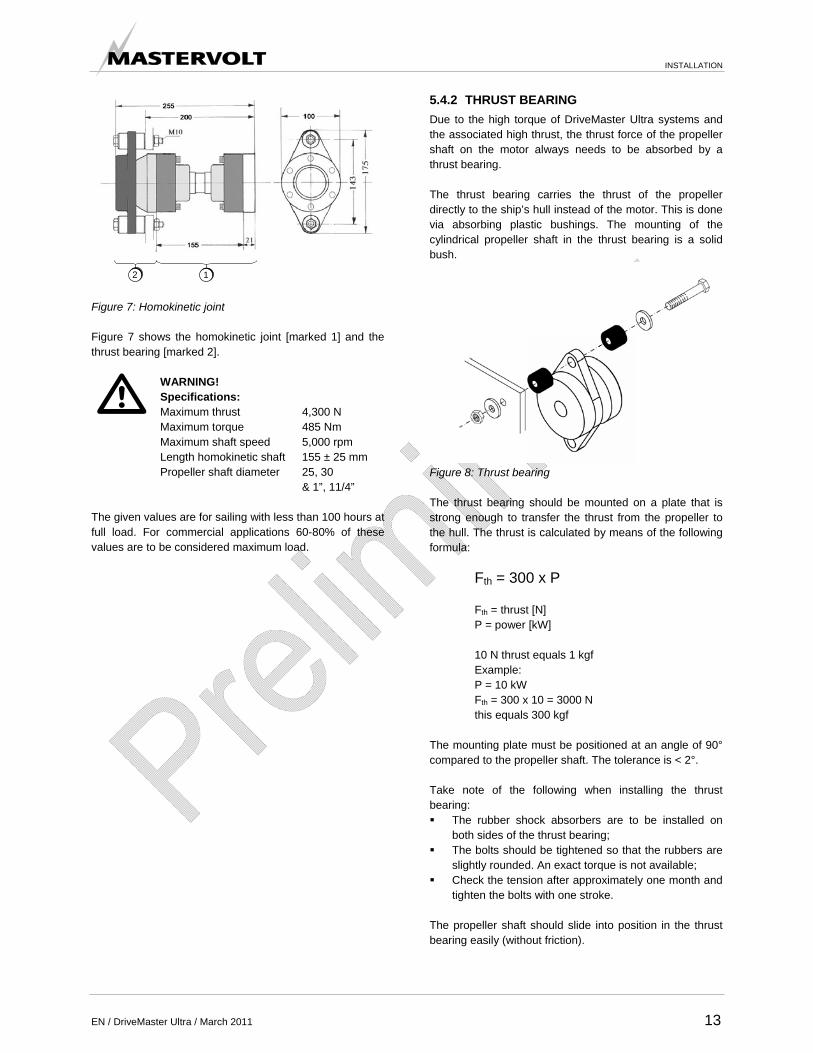
12 Figure 7: Homokinetic joint Figure 7 shows the homokinetic joint [marked 1] and the thrust bearing [marked 2].
WARNING! Specifications: Maximum thrust 4,300 N Maximum torque 485 Nm Maximum shaft speed 5,000 rpm Length homokinetic shaft 155 ± 25 mm Propeller shaft diameter 25, 30 & 1”, 11/4”
The given values are for sailing with less than 100 hours at full load. For commercial applications 60-80% of these values are to be considered maximum load.
5.4.2 THRUST BEARING Due to the high torque of DriveMaster Ultra systems and the associated high thrust, the thrust force of the propeller shaft on the motor always needs to be absorbed by a thrust bearing. The thrust bearing carries the thrust of the propeller directly to the ship’s hull instead of the motor. This is done via absorbing plastic bushings. The mounting of the cylindrical propeller shaft in the thrust bearing is a solid bush.
Figure 8: Thrust bearing The thrust bearing should be mounted on a plate that is strong enough to transfer the thrust from the propeller to the hull. The thrust is calculated by means of the following formula:
Fth = 300 x P Fth = thrust [N] P = power [kW] 10 N thrust equals 1 kgf Example: P = 10 kW Fth = 300 x 10 = 3000 N this equals 300 kgf
The mounting plate must be positioned at an angle of 90° compared to the propeller shaft. The tolerance is < 2°. Take note of the following when installing the thrust bearing: The rubber shock absorbers are to be installed on
both sides of the thrust bearing; The bolts should be tightened so that the rubbers are
slightly rounded. An exact torque is not available; Check the tension after approximately one month and
tighten the bolts with one stroke. The propeller shaft should slide into position in the thrust bearing easily (without friction).

INSTALLATION
14 March 2011 / DriveMaster Ultra / EN
1
2
3
4
1 - Plastic bushings 2 - Propeller shaft 3 - Thrust bearing 4 - Sleeve
Figure 9: Propeller shaft in the thrust bearing Take the following steps: 1. Mount the thrust bearing by using the bushings
[marked 1]. 2. Lubricate the propeller shaft [2] and the exterior of the
sleeve [4] with oil and grease. 3. Insert the propeller shaft [2] into the sleeve [4] until it
sticks out approximately 5 to 10 mm. 4. Tighten the bolts of the clamping device inside the
thrust bearing [3] crosswise and diagonally by hand until they are properly fastened.
5. Tighten the bolts crosswise and diagonally with a torque wrench with half a stroke each time: M6 = 17 Nm.
The sleeve has two extra holes. This allows the sleeve to be removed. To do so, follow these steps: 1. Loosen all bolts. 2. Use two M6 bolts and screw them in the two pin
holes. 3. Remove the bolts crosswise until the sleeve pops off
the shaft. The propeller shaft in the thrust bearing is not included in the delivery.
5.5 MOTOR CONTROLLER Note the following when installing the motor controller: The motor controller must be mounted at a dry, well-
protected and accessible location in the boat; Take note of the length of the motor cables since you
can not shorten or extend these cables; Never install a controller near (or in the same location)
as a so-called wet / open battery; The controller must be able to take in enough cool air,
make sure there is adequate ventilation; Ensure that the intake opening cannot be blocked and
do not cover up the outlet hole. After the most suitable location in the boat has been determined, the controller can be mounted in place.
Figure 10: Motor controller mounting The motor controller must be mounted by using four bolts, as shown in Figure 10. See chapter 8 for the controller dimensions.

INSTALLATION
EN / DriveMaster Ultra / March 2011 15
5.6 DISPLAY The display is usually mounted on the control console of the boat. The location of the display is not critical, it is important that (rain) water does not remain on the display and can run off. Upright or slightly slanted installation is recommended. This does not apply to an indoor arrangement. The display requires a rectangular 138 mm by 92 mm (width by height) panel cut-out. See chapter 8 for the display dimensions. 5.7 JOYSTICK The joystick is mounted, for instance, vertically on the control console. Note the following: The joystick is splash proof only. Therefore the
joystick should not continuously be in contact with water. Position the joystick carefully;
The lever has to be able to rotate freely in both directions;
Choose the location so that the risk of turning the lever in the unwanted direction is minimal.
5.8 WIRING Each system has the following wiring: Main battery power connections; Control cables, including preassembled connectors; Preassembled motor cables, including clamp
connection (U-V-W); Motor sensor cable, including preassembled
connectors. The power cables for connecting the batteries to the motor controller are not included in the delivery. The connection of the cables is explained in the following sections. Connect the cables in the following order: 1. Connect the motor cables. 2. Connect the signal cables. 3. Connect the battery power cables. See the block diagram in chapter 3 and the wiring diagram in Figure 11.

INSTALLATION
16 March 2011 / DriveMaster Ultra / EN
Battery
Fuse
Main switch
Motor controller
Motor sensor cable
Motor
Ignition
Joystick
Display
w v u
+
+
_
_
Figure 11: Wiring diagram (the shown motor controller belongs to the DriveMaster Ultra 3.5, but the same connections exist on the other systems) The battery and joystick are not included in the system. For ordering information, see chapter 9.

INSTALLATION
EN / DriveMaster Ultra / March 2011 17
5.8.1 MOTOR CONTROLLER CONNECTIONS
1
2
3 4 5 6
7
8
9
Figure 12: Motor controller (the shown motor controller belongs to the DriveMaster Ultra 3.5, but the same connections exist on the other systems) Figure 12 gives an overview of the connections on the motor controller. The connections include: 1. – Pole for battery 2. + Pole for battery (incl. main switch and fuse) 3. Fuse holder - Fuse = Fast 4 A 4. Connection for computer 5. 12 pin connector for display, joystick and ignition 6. Motor sensor cable 7. U wire hole from the motor 8. V wire hole from the motor 9. W wire hole from the motor
5.8.2 CONNECTION OF MOTOR CABLES
u
v
w
y
x
z
Figure 13: Connecting points for motor cables (the shown motor controller belongs to the DriveMaster Ultra 3.5, but the same connections exist on the other systems)
CAUTION! Motor cables must not be shortened or extended. Connections must be preserved with acid-free Vaseline.
To connect the motor cables and motor sensor cable, follow these steps: The motor cables are already fixed to the motor. 1. Remove the metal cover from the motor controller by
removing the screws marked [x], [y] and [z] in Figure 13, on both sides of the controller.
2. Pull the three cables through the corresponding holes at the front of the controller. Make sure that the U, V and W cables are placed in the correct location.
3. Connect the three motor cables labeled [U, V, W] onto the correspondingly marked connections on the motor controller (see Figure 13). Install the cables using the supplied M8 bolts and tighten them with 9.6 ± 0.9 Nm. Use a torque wrench.
4. Close the cover carefully and tighten the screws. The motor sensor cable is already connected to the motor controller. 5. Connect the motor sensor cable from the motor
controller to the motor with the preassembled cable with bayonet plug.
6. Turn the chrome ring clockwise until the bayonet ring is locked.

INSTALLATION
18 March 2011 / DriveMaster Ultra / EN
5.8.3 CONNECTION OF SIGNAL CABLES
Figure 14: Signal cable connector Follow these steps to connect the display, joystick and motor switch to the motor controller: 1. Determine the position of the display, joystick and
motor switch. 2. Bring the supplied signal cable to this position. 3. Connect the display, joystick and motor switch with
the preassembled plugs. 4. Connect the 12-pin plug at the other end of the cable
with the 12-pin connector that is located at the front of the motor controller.
5. Lock the plug by turning the chrome ring a quarter of a stroke.
CAUTION! CAN-bus control signals are transferred through this cable. Therefore, never run this cable along power cables or 230 Volt wiring. Secure cables properly; loose cables can eventually cause malfunctions.
5.8.4 CONNECTION OF POWER CABLES
WARNING! Make sure that when connecting the battery and the motor controller, the fuse has been removed and the main switch is turned off.
Figure 15: Quick connect couplings for power cable Notice the following when connecting the cables: The positive terminal is clearly marked with a red
mark on the motor controller; The main switch must be mounted at an accessible
location between the fuse and the motor controller, so that the system can be disconnected from the battery in case of an emergency or in case of maintenance;
The fuse must be placed as close as possible to the battery to ensure maximum wiring protection;
The + cable runs from the battery to the fuse and the – cable runs from the battery to the – pole of the controller.
Specifications for connecting the power cables. Motor controller > 35 mm2 Fuse T 225 Ampere Power 3.5 kW Voltage 48 Volts Two quick-connect couplings are included for connection to the motor controller (see Figure 16).
Figure 16: Quick connect couplings for the motor controller Follow these steps to connect the quick-connect couplings: 1. Install the couplings with care at the ends of the
cables. 2. Place the couplings on the controller. 3. Turn the couplings one stroke counter-clockwise. The
cable is now secured and cannot get loose as a result of vibration.
Refer to the manual of the battery supplier for more information about the connection and location of the battery.

INSTALLATION
EN / DriveMaster Ultra / March 2011 19
Follow these steps after installation and before switching on the power: 1. Check all connections again. 2. Check the voltage of the battery. 3. When you are convinced that everything has been
connected properly, turn the main switch on. 5.9 CALIBRATION The main calibration is done in the factory. Every time the system is turned on, it will perform a self-diagnosis first. Follow these steps: 1. Put the Joystick in the neutral position. 2. Turn on the system with the motor switch. The display lights up and the main relay in the motor controller will close if everything is connected correctly. 3. Move the joystick forward and backward to check the
system and the rotation of the propeller. 4. Check the system for unwanted noise and vibration.
CAUTION! Steps 3 and 4 must be done carefully so that the bearings of the shaft will not be damaged in case the propeller shaft is not properly lubricated.
5.10 COMMISSIONING The factory settings of the DriveMaster Ultra are optimal for most installations. For some applications however, it is desirable to change these settings. Therefore, several adjustments can be made. If your DriveMaster Ultra is not new, you have to take into account that previous users may have changed the settings. Let a certified installer set the DriveMaster Ultra to your preferences in case of doubt. To change the controller software, a computer or laptop or the Curtis 1311 Handheld Programmer can be used. This 1311 Handheld Programmer simplifies adjustments, programming, testing and diagnosing. It provides a fast and easy interface to the motor controller. The connector for the computer or Handheld Programmer can be found on the front of the motor controller, marked [4] in Figure 12.
Figure 17: 1311 Handheld programmer Please refer to the Curtis 1311 Handheld manual for further operating instructions.

MAINTENANCE
20 March 2011 / DriveMaster Ultra / EN
6 MAINTENANCE 6.1 PREVENTIVE MAINTENANCE Check your whole system regularly on the following points: Check the bilge and motor compartment for unwanted
moisture or water; Check the operation of the automatic bilge pump; Check the system for irregularities, such as abnormal
noise, vibration and wear. Keep the system always connected (even in winter storage) to the shore connection. This will keep the batteries in 100% condition and prevents self-discharging of batteries. If the system is not going to be used for a long time and a permanent shore connection is not available, charge the batteries for 100% and remove the fuse. 6.2 MAINTENANCE The DriveMaster Ultra basically does not need maintenance. However, you should be alert for moisture and salt, which can permanently damage your system. The body of the motor and motor controller can be cleaned with a dry or slightly damp cloth. Never use water or a solvent to clean the motor or motor controller. Always contact your dealer if you notice strange noises, vibrations or non-traceable error messages on the display. Have your whole system checked by a qualified installer every two years. This will keep your system in optimal condition.

TROUBLE SHOOTING
EN / DriveMaster Ultra / March 2011 21
7 TROUBLE SHOOTING In case of a failure, the DriveMaster Ultra display shows an error code to help you find the cause. If you cannot solve a problem with the aid of the fault finding table below, contact your local Mastervolt Service Centre. See www.mastervolt.com. Make sure you have the article and serial number close at hand.
At the right side of the display is a LED alarm triangle (see Figure 2). This triangle displays the following colours in case of an alarm: Yellow: low battery level; Red: alarm/error code system.
The number of the alarm is shown in the display, see Figure 18.
FAULT 24
Figure 18: Display showing error code The following table shows the most common errors. Code Error Solution 16 Controller overheated > 95° Let motor controller cool down and check the cooling of the
housing. 22 Controller too hot > 85° Power to motor is automatically reduced until the temperature has
dropped to a safe value. 23 Low voltage warning + yellow LED signal Battery voltage too low. Power is automatically reduced.
Charge batteries as soon as possible! 24 Battery voltage too high. Motor controller
cannot operate regeneratively Standard security to prevent overloading the battery. When the battery can take up current again, the regeneration will automatically start.
28 Motor temperature too high > 135° Power is automatically reduced by the motor controller until the temperature has dropped to a safe value.
47 Joystick is not in neutral during switch on of the system
Put joystick in neutral.
Errors are reset with the motor switch, by turning it off and on again.

TECHNICAL DATA
22 March 2011 / DriveMaster Ultra / EN
8 TECHNICAL DATA 8.1 TECHNICAL SPECIFICATIONS Model DriveMaster Ultra 3.5 5 7.5 10 20 Article number 140300350 140300500 140300750 140301000 140302000 Battery Nominal battery voltage 48 V 96 V Battery voltage 25.2 – 60.0 V 50.4 – 120 V Minimal battery capacity 200 Ah 300 Ah 450 Ah 600 Ah 600 Ah AC Number of phases 3 Nominal phase current 85 A 150 A 150 A 225 A 225 A Maximum phase current 250 A 350 A 350 A 450 A 450 A PWM operating frequency 10 kHz Maximum encoder frequency 15 kHz Output frequency 0-300 Hz Control adjustment Motor type Asynchronous Maximum motor power < 3.5 kW
(S1) < 5 kW
(S1) < 7.5 kW
(S2-120 min) < 10 kW
(S1) <20 kW
(S2-120 min) Sensor SKF – sensor bearing Encoder pulses per rotation 64 Read motor parameters Automatic via Auto fine tuning Standby mode Blocked by software Communication CAN open, Nodes 2.0 Standard ID type 11 – bit Baud rate < 500 Kbps Safety Undervoltage 19 V 38 V Overvoltage 63 V 126 V Current Maximum allowed value is programmable Motor power Maximum allowed value is programmable Motor speed 1400 rpm 1400 rpm 1400 rpm 1400 rpm 1400 rpm Related torque 24 Nm 34 Nm 51 Nm 68 Nm 136 Nm Thermal safety Shuts down the controller when overheated Coupling limitation Adjustable via software Environment Temperature -40 - 50 °C Protection class motor controller electronics IP 65 Display upper side IP 65 Weight Motor 37.2 kg 65 kg 69 kg 118 kg 176 kg Shaft flange 0.7 kg 0.7 kg 0.7 kg 0.8 kg 0.8 kg Motor cable (U V W) standard length 2.5 m 1.8 kg 2.2 kg 2.2 kg 2.2 kg 2.2 kg Motor controller 9.7 kg 13 kg 13 kg 20.6 kg 20.6 kg Display 0.4 kg 0.4 kg 0.4 kg 0.4 kg 0.4 kg Wiring assembly (motor controller – display) 0.7 kg 0.7 kg 0.7 kg 0.7 kg 0.7 kg Total weight system 50.5 kg 81.9 kg 85.9 kg 142.7 kg 200.7 kg

8.2 DIMENSIONS 8.2.1 DISPLAY
Figure 19: Dimensions of display in mm
Figure 20: Dimensions of display in inches

8.2.2 MOTOR CONTROLLER
Front Side
Bottom
313
190214
30
8
220
280
30
280
295
184
214
184
Figure 21: Dimensions of DriveMaster Ultra 3.5 motor controller in mm
SideFront
Bottom
8.43
7.23
11.02
11.61
7.23
1.18
8.66
8.43
0.31
11.0
2
7.48
12.3
1
1.19
Figure 22: Dimensions of DriveMaster Ultra 3.5 motor controller in inches

SideFront
Top
205
254
196
355300
380
30
R6
4
240
R
30
230
33
Figure 23: Dimensions of DriveMaster Ultra 5 and 7.5 motor controller in mm
1.18
R0.22
9.45
0.14R
9.06
1.18
1.30
8.05
10.00
7.70
SideFront
Top
13.9811.81
14.94
Figure 24: Dimensions of DriveMaster Ultra 5 and 7.5 motor controller in inches

404
454
196
430
30
R6
3024
0
33
R4
320300
349
Front Side
Top
Figure 25: Dimensions of DriveMaster Ultra 10 and 20 motor controller in mm
12.6011.81
13.72
15.91
17.87
7.72
1.18
9.45
1.18
R0.22
16.93
1.30
R0.14
SideFront
Top
Figure 26: Dimensions of DriveMaster Ultra 10 and 20 motor controller in inches

8.2.3 ASYNCHRONOUS MOTOR
1226
6
185
250217
100
407
140
7R
195
2114
7
202 106
112
Side
Bottom
Front
Figure 27: Dimensions of DriveMaster Ultra 3.5 motor in mm
Bottom
Side Front
9.83
3.92
5.51
16.0
3
8.547.68
R0.26
7.28 0.83
5.79
7.95 4.17
4.39
0.47
10.4
9
Figure 28: Dimensions of DriveMaster Ultra 3.5 motor in inches

FrontSide
Bottom
294
15
260420498
381
136
206226
149
R5
2021
178
10
130
17
100
Figure 29: Dimensions of DriveMaster Ultra 5 motor in mm
15.02
16.5419.59
5.36
7.01
0.78
5.128.11
0.390.68
8.90
R
5.85
0.20
0.84
3.92
11.5
90.
58
10.25Bottom
FrontSide
Figure 30: Dimensions of DriveMaster Ultra 5 motor in inches
219
226
20
1710
149
215R
206
100
420498
375
136
Side Front
Bottom
260
15
293
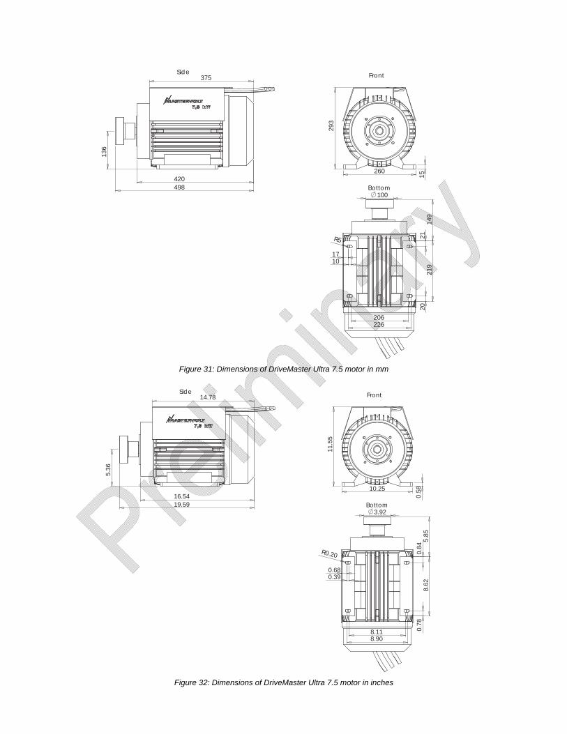
Figure 31: Dimensions of DriveMaster Ultra 7.5 motor in mm
Side Front
Bottom
10.25
0.58
11.5
5
14.78
16.5419.59
5.36
0.78
R0.20
8.62
0.84
0.68
8.90
0.39
5.85
8.11
3.92
Figure 32: Dimensions of DriveMaster Ultra 7.5 motor in inches

682
163
264
245
254
10
184
25
R7
27
26
244
100
Front
Bottom
Side
318 18
390
Figure 33: Dimensions of DriveMaster Ultra 10 motor in mm
Bottom
FrontSide
12.53
0.69
15.3
4
26.86
6.42
9.64
1.01
10.0
0
1.07
7.22
0.98
10.39
0.39
R0.28
9.61
3.92
Figure 34: Dimensions of DriveMaster Ultra 10 motor in inches

584712
419
184
34
292
10
219
22
38
241
70
7R
272
102
20360
Side Front
Bottom
Figure 35: Dimensions of DriveMaster Ultra 20 motor in mm
0.28
0.87
1.340.39
11.50
8.63
10.71
2.76
9.49
1.50
R
4.02
22.9928.05
16.4
9
7.23
FrontSide
Bottom
0.7814.17
Figure 36: Dimensions of DriveMaster Ultra 20 motor in inches

9 ORDERING INFORMATION Part number Description 142000260 142000261 142000262 142000263
3D motor mounting set DriveMaster Ultra 3.5 DriveMaster Ultra 5 and 7.5 DriveMaster Ultra 10 DriveMaster Ultra 20 The DriveMaster can be mounted in the boat with a support bracket that is adjustable in height, width and angle. The support bracket has a total weight of 11.3 kg for the 3.5, 13.8 kg for the 5 and 7.5, 15.8 kg for the 10 and 18 kg for the 20. The support bracket is delivered with 4 motor adjust feet and vibration absorbers.
Figure 37: Support bracket
142000440 142000441
A-flex thrust bearing + homokinetic coupling ø25mm A-flex thrust bearing + homokinetic coupling ø30mm Characteristics of an A-flex coupling: Production of sound and vibration has decreased by 90%; Simplification of motor / propeller shaft systems; Lining procedure is easy by self-targeting clamping hub in the thrust bearing; Can absorb lining differences of up to 2 x 8°.
A complete set consists of: homokinetic drive shaft, thrust bearing with sleeve, optional adapter, bolts, nuts and washers. See the ordering details. Thrust bearing The thrust bearing carries the high torque of DriveMaster Ultra systems and the associated high thrust force of the propeller shaft on the motor directly to the ship’s hull instead of the motor. The thrust bearing aids in realizing a smooth and low noise propulsion system and absorbs all axial forces that need to be dealt with. Low friction ensures a long life propulsion system and the ability to operate a more powerful engine and propeller. Homokinetic joint The homokinetic joint is mounted between the thrust bearing and the motor flange. Its purpose is to ensure installation of motor and propeller shaft without centering problems. After mounting, the homokinetic joint provides a few millimeters of movement to the front and the back of the center axle. ATTENTION! Specify the propeller shaft diameter when ordering.
141500010 ControlMaster Casual – single version, side mount 141500030 ControlMaster Sport – single version, side mount 141500120 ControlMaster Sport T – single version, top mount 141500220 ControlMaster Sport TD – double version, top mount 142000355 Extension cable set 6 metres