Embed Size (px)
Citation preview

Magnet Code 3.0 for Arduino Interface User‟s Manual www.magnetcode.com
Phone: +6012-297 9320 Fax: +603-8948 7451 Email: [email protected] i
Magnet Code 3.0 Smartphone Controller
with Arduino Companion
Solution for Advanced and Creative Projects
Integrate existing Microcontroller or Laptop projects with Smartphone Controller to transform all past project topics or ideas to become much more advanced and creative project topics. By installing a Magnet Code platform in your Smartphone, you can easily apply all the features in your Smartphone to develop various types of advanced and creative projects.
www.magnetcode.com
Magnet Code 3.0 for Arduino Interface User‟s Manual www.magnetcode.com
Phone: +6012-297 9320 Fax: +603-8948 7451 Email: [email protected] ii
Disclaimer
Magnet Code software and this workshop note are owned by Bizchip Technology Centre and are
protected by law and international copyright. Therefore, you should treat this workshop note like any
other copyrighted material (e.g. book). The manual and the compiler must not be copied, partially or
as whole without the written consent from Bizchip Technology Centre. The PDF-edition of the
workshop note can be printed for private or local use, but not for distribution. Modifying the manual or
Magnet Code software is strictly prohibited.
High Risk Activities
The Magnet Code software is not fault-tolerant and is not designed, manufactured or intended for use
or resale as an online control equipment in hazardous environments requiring fail safe performance,
such as in the operation of nuclear facilities, aircraft navigation or communication system, air traffic
control, direct life support machines or weapons systems, in which the failure of the Software could
lead directly to death, personal injury or severe physical or environmental damage (“High Risk
Activities”). Bizchip and its suppliers specifically disclaim any express or implied warranty of fitness
for high risk activities.
License Agreement
By using the Magnet Code software, you agree to the terms of this agreement. Only one person may
use a licensed version of the Magnet Code software at one time.
This manual covers Magnet Code version 3.0 and the related topics. Newer versions may contain
change without prior notice.
Software bug reports
The Magnet Code software has been carefully tested and debugged. It is however not possible to
guarantee a 100% error free product. If you would like to report a bug, please contact us at
[email protected]. Please include the following information in your bug report:
- Your phone‟s IMEI number
- Your phone‟s operating system
- Description of a bug
Contact Us
Bizchip Technology Centre
Phone: +6012-297 9320 Fax: +603-89487451
Web: www.magnetcode.com Email: [email protected]
Magnet Code 3.0 for Arduino Interface User‟s Manual www.magnetcode.com
Phone: +6012-297 9320 Fax: +603-8948 7451 Email: [email protected] iii
Table of Contents
Chapter 1: Introduction to Magnet Code 1.1 Types of Smartphone Apps 1
1.2 Why use Smartphone? 1
1.3 How to use Smartphone control devices? 1
1.4 The power of fusion 2
1.5 Smartphone VS Microcontroller VS Laptop 3
1.6 Tips to transform old projects with Smartphone 4
1.7 What is Magnet Code? 6
1.8 Magnet Coe interfacing 6
1.9 Smartphone requirement 7
1.10 Magnet Code 3.0 basic features 7
1.11 Magnet Code 3.0 add on toolbox 8
1.12 Steps to get Magnet Code 3.0 9
Chapter 2: Graphical User Interface
2.1 Main page 11
2.2 Setting page 12
2.3 About page 13
2.4 Background 13
2.5 Button 14
2.6 Command box 15
2.7 Email 16
2.8 File 18
2.9 Layout 19
2.10 LCD 20
2.11 SMS 21
2.12 Startup Screen 22
2.13 Title 23
2.14 Transfer License 23
2.15 Color setting 24
2.16 Text font setting 25
2.17 Select picture setting 25
Magnet Code 3.0 for Arduino Interface User‟s Manual www.magnetcode.com
Phone: +6012-297 9320 Fax: +603-8948 7451 Email: [email protected] iv
2.18 Text size setting 26
Chapter 3: Getting Started
3.1 Setup Magnet Code station 27
3.2 Test Arduino Microcontroller 30
3.3 Test App-Link Bluetooth module 33
3.4 Magnet Code command format 36
3.5 Initialize Magnet Code interfacing 36
3.6 Send Magnet Code command 37
3.7 Receive Magnet Code data 38
Chapter 4: Output Toolbox
4.1 Output toolbox command list 39
4.2 Project 1: Alert user with vibration and turn on camera LED when door
is open
Objective: Control phone vibration using Camera LED
40
Chapter 5: LCD Toolbox
5.1 LCD toolbox command list 43
5.2
Project 2: Show alert message on LCD when intruder is detected
Objective: Change LCD properties
47
5.3 Project 3: Visitor counter which shows the total number of visitors on
the Smartphone
Objective: Show Variable on LCD
49
5.4 Project 4: Show patient temperature on Smartphone
Objective: create data list on LCD
52
Chapter 6: Button Toolbox
6.1 Button toolbox command list 54
6.2 Project 5: Fire alarm which is able to show system status on
Smartphone
Objective: Change button properties
54
6.3 Project 6: Control bulb on/off using Smartphone
Objective: Single byte control using button
58
Magnet Code 3.0 for Arduino Interface User‟s Manual www.magnetcode.com
Phone: +6012-297 9320 Fax: +603-8948 7451 Email: [email protected] v
6.4 Project 7: Control motor direction using Smartphone
Objective: String control using button
61
Chapter 7: Audio Toolbox (optional add on)
7.1 Audio toolbox command list 63
7.2 Project 8: Wheelchair timer for rehabilitation purpose
Objective: Play an audio file
65
7.3 Project 9: Communication device for patient who is unable to speak
properly
Objective: Record and play an audio file
68
7.4 Project 10: Remote control for speaker sound volume
Objective: Control speaker sound volume
72
Chapter 8: Photo Toolbox (optional add on)
8.1 Photo toolbox command list 74
8.2 Project 11: Security system for the computer lab
Objective: Capture image and record
76
Chapter 9: Video Toolbox (optional add on)
9.1 Video toolbox command list 80
9.2 Project 12: Record and play back video when room door is open
Objective: Record and play video
82
Chapter 10: Sensor Toolbox (optional add on)
10.1 Sensor toolbox command list 84
10.2 Project 13: Power failure detector using Smartphone
Objective: Apply charging sensor
87
10.3
Project 14: Safety helmet with drowsy detection
Objective: Apply acceleration sensor
89
Magnet Code 3.0 for Arduino Interface User‟s Manual www.magnetcode.com
Phone: +6012-297 9320 Fax: +603-8948 7451 Email: [email protected] vi
Chapter 11: GPS Toolbox (optional add on)
11.1 GPS toolbox command list 93
11.2 Project 15: Car speed detector
Objective: Apply GPS speed detection device
94
Chapter 12: Speech Toolbox (optional add on)
12.1 Speech toolbox command list 98
12.2 Project 16: Visitor counter with greeting
Objective: Apply test to speech feature
99
Chapter 13: SMS Toolbox (optional add on)
13.1 SMS toolbox command list 101
13.2 Project 17: Fire alarm with SMS alert
Objective: Sent SMS
106
13.3 Project 18: Paddy field water level controller
Objective: Control single output using SMS
107
13.4 Project 19: Smart home monitoring system
Objective: Receive and send SMS
108
13.5 Project 20: Smart lighting system
Objective: Control multi-output using sms
109
Chapter 14: Email Toolbox (optional add on)
14.1 Email toolbox command list 117
14.2 Project 21: Lecturer office alarm
Objective: Send email with attachment file
118
Chapter 15: Database Toolbox (optional add on)
15.1 Sensor toolbox command list 120
15.2 Project 22: Environment brightness recorder
Objective: Save data in excel file
127
Chapter 16: Magnet Code Project Topics
16.1 Magnet Code for agriculture 130
16.2 Magnet Code for biomedical 132
16.3 Magnet Code for building automation 133
16.4 Magnet Code for transportation 136
Magnet Code 3.0 for Arduino Interface User‟s Manual www.magnetcode.com
1 Phone: +6012-297 9320 Fax: +603-8948 7451 Email: [email protected]
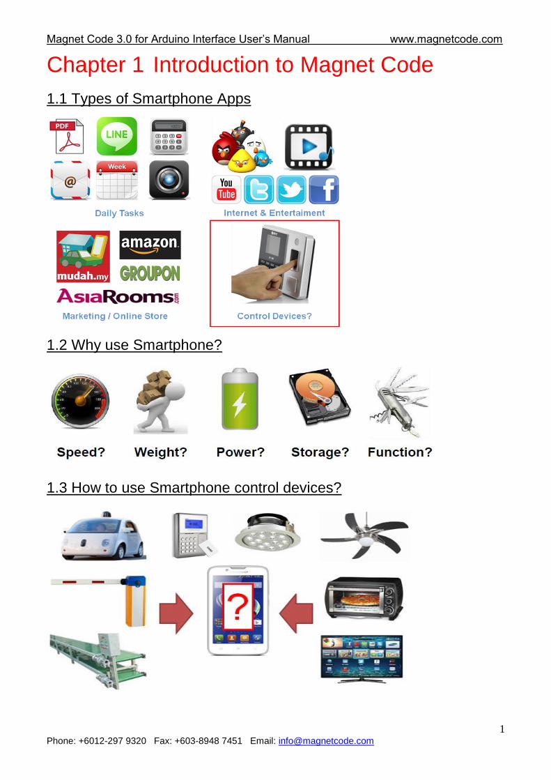
Chapter 1 Introduction to Magnet Code
1.1 Types of Smartphone Apps
1.2 Why use Smartphone?
1.3 How to use Smartphone control devices?
Magnet Code 3.0 for Arduino Interface User‟s Manual www.magnetcode.com
Phone: +6012-297 9320 Fax: +603-8948 7451 Email: [email protected] 2
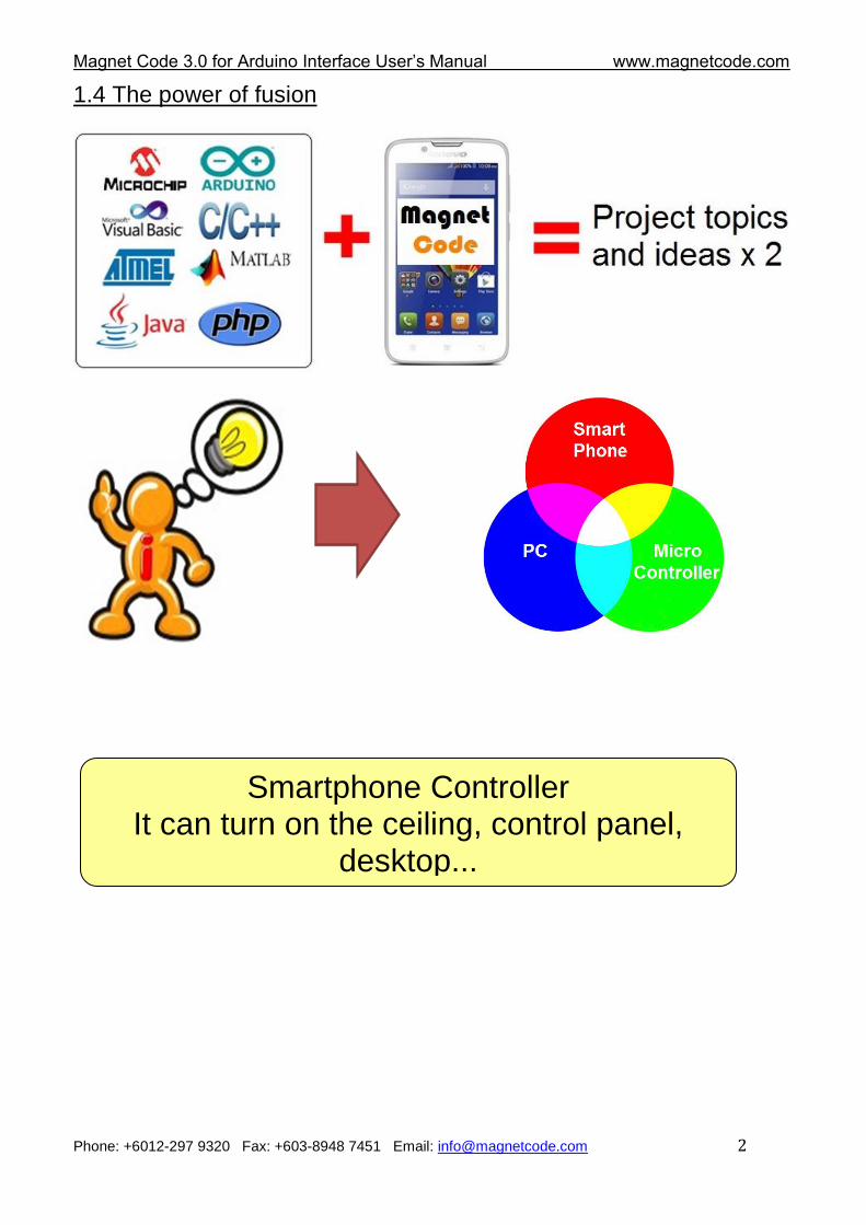
1.4 The power of fusion
Smartphone Controller It can turn on the ceiling, control panel,
desktop...
Magnet Code 3.0 for Arduino Interface User‟s Manual www.magnetcode.com
Phone: +6012-297 9320 Fax: +603-8948 7451 Email: [email protected] 3
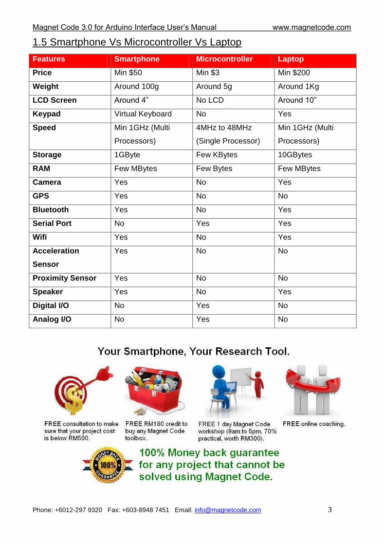
1.5 Smartphone Vs Microcontroller Vs Laptop
Features Smartphone Microcontroller Laptop
Price Min $50 Min $3 Min $200
Weight Around 100g Around 5g Around 1Kg
LCD Screen Around 4” No LCD Around 10”
Keypad Virtual Keyboard No Yes
Speed Min 1GHz (Multi
Processors)
4MHz to 48MHz
(Single Processor)
Min 1GHz (Multi
Processors)
Storage 1GByte Few KBytes 10GBytes
RAM Few MBytes Few Bytes Few MBytes
Camera Yes No Yes
GPS Yes No No
Bluetooth Yes No Yes
Serial Port No Yes Yes
Wifi Yes No Yes
Acceleration
Sensor
Yes No No
Proximity Sensor Yes No No
Speaker Yes No Yes
Digital I/O No Yes No
Analog I/O No Yes No
Magnet Code 3.0 for Arduino Interface User‟s Manual www.magnetcode.com
Phone: +6012-297 9320 Fax: +603-8948 7451 Email: [email protected] 4
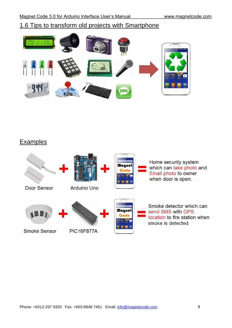
1.6 Tips to transform old projects with Smartphone
Examples
Magnet Code 3.0 for Arduino Interface User‟s Manual www.magnetcode.com
Phone: +6012-297 9320 Fax: +603-8948 7451 Email: [email protected] 5
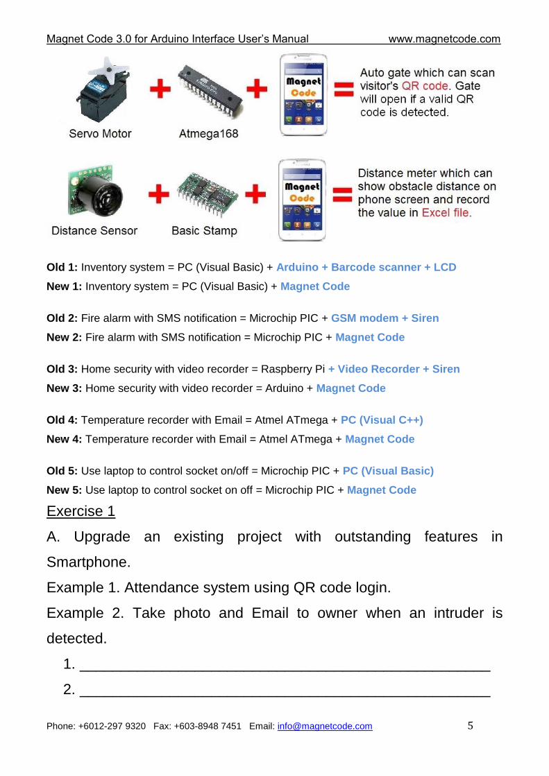
Old 1: Inventory system = PC (Visual Basic) + Arduino + Barcode scanner + LCD
New 1: Inventory system = PC (Visual Basic) + Magnet Code
Old 2: Fire alarm with SMS notification = Microchip PIC + GSM modem + Siren
New 2: Fire alarm with SMS notification = Microchip PIC + Magnet Code
Old 3: Home security with video recorder = Raspberry Pi + Video Recorder + Siren
New 3: Home security with video recorder = Arduino + Magnet Code
Old 4: Temperature recorder with Email = Atmel ATmega + PC (Visual C++)
New 4: Temperature recorder with Email = Atmel ATmega + Magnet Code
Old 5: Use laptop to control socket on/off = Microchip PIC + PC (Visual Basic)
New 5: Use laptop to control socket on off = Microchip PIC + Magnet Code
Exercise 1
A. Upgrade an existing project with outstanding features in
Smartphone.
Example 1. Attendance system using QR code login.
Example 2. Take photo and Email to owner when an intruder is
detected.
1. __________________________________________________
2. __________________________________________________
Magnet Code 3.0 for Arduino Interface User‟s Manual www.magnetcode.com
Phone: +6012-297 9320 Fax: +603-8948 7451 Email: [email protected] 6
B. Replace existing modules by features in Smartphone.
Example 1. Replace GSM modem by Smartphone.
Example 2. Replace TV or Radio remote control by Smartphone.
1. __________________________________________________
2. __________________________________________________
1.7 What is Magnet Code?
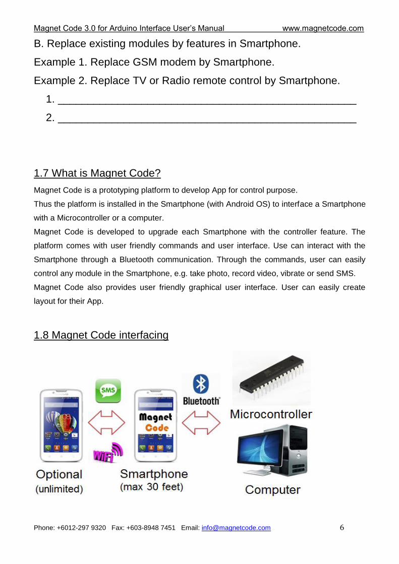
Magnet Code is a prototyping platform to develop App for control purpose.
Thus the platform is installed in the Smartphone (with Android OS) to interface a Smartphone
with a Microcontroller or a computer.
Magnet Code is developed to upgrade each Smartphone with the controller feature. The
platform comes with user friendly commands and user interface. Use can interact with the
Smartphone through a Bluetooth communication. Through the commands, user can easily
control any module in the Smartphone, e.g. take photo, record video, vibrate or send SMS.
Magnet Code also provides user friendly graphical user interface. User can easily create
layout for their App.
1.8 Magnet Code interfacing
Magnet Code 3.0 for Arduino Interface User‟s Manual www.magnetcode.com
Phone: +6012-297 9320 Fax: +603-8948 7451 Email: [email protected] 7
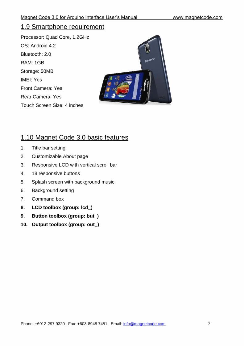
1.9 Smartphone requirement
Processor: Quad Core, 1.2GHz
OS: Android 4.2
Bluetooth: 2.0
RAM: 1GB
Storage: 50MB
IMEI: Yes
Front Camera: Yes
Rear Camera: Yes
Touch Screen Size: 4 inches
1.10 Magnet Code 3.0 basic features
1. Title bar setting
2. Customizable About page
3. Responsive LCD with vertical scroll bar
4. 18 responsive buttons
5. Splash screen with background music
6. Background setting
7. Command box
8. LCD toolbox (group: lcd_)
9. Button toolbox (group: but_)
10. Output toolbox (group: out_)
Magnet Code 3.0 for Arduino Interface User‟s Manual www.magnetcode.com
Phone: +6012-297 9320 Fax: +603-8948 7451 Email: [email protected] 8
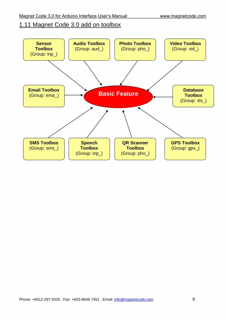
1.11 Magnet Code 3.0 add on toolbox
Basic Feature
Sensor Toolbox
(Group: inp_)
Audio Toolbox (Group: aud_)
Photo Toolbox (Group: pho_)
Video Toolbox (Group: vid_)
SMS Toolbox (Group: sms_)
Speech Toolbox
(Group: inp_)
QR Scanner Toolbox
(Group: pho_)
GPS Toolbox (Group: gps_)
Email Toolbox (Group: ema_)
Database Toolbox
(Group: xls_)
Magnet Code 3.0 for Arduino Interface User‟s Manual www.magnetcode.com
Phone: +6012-297 9320 Fax: +603-8948 7451 Email: [email protected] 9
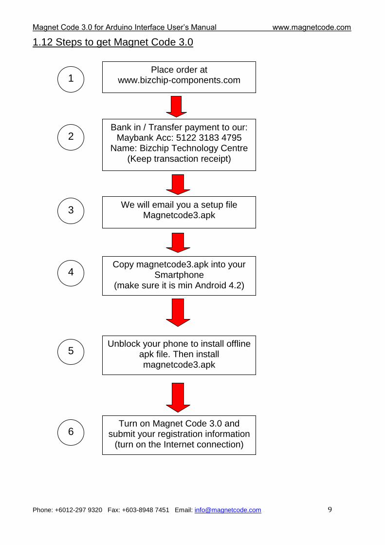
1.12 Steps to get Magnet Code 3.0
Place order at www.bizchip-components.com
We will email you a setup file Magnetcode3.apk
Bank in / Transfer payment to our: Maybank Acc: 5122 3183 4795
Name: Bizchip Technology Centre (Keep transaction receipt)
Copy magnetcode3.apk into your Smartphone
(make sure it is min Android 4.2)
Unblock your phone to install offline apk file. Then install magnetcode3.apk
Turn on Magnet Code 3.0 and submit your registration information
(turn on the Internet connection)
1
2
3
4
5
6
Magnet Code 3.0 for Arduino Interface User‟s Manual www.magnetcode.com
Phone: +6012-297 9320 Fax: +603-8948 7451 Email: [email protected] 10
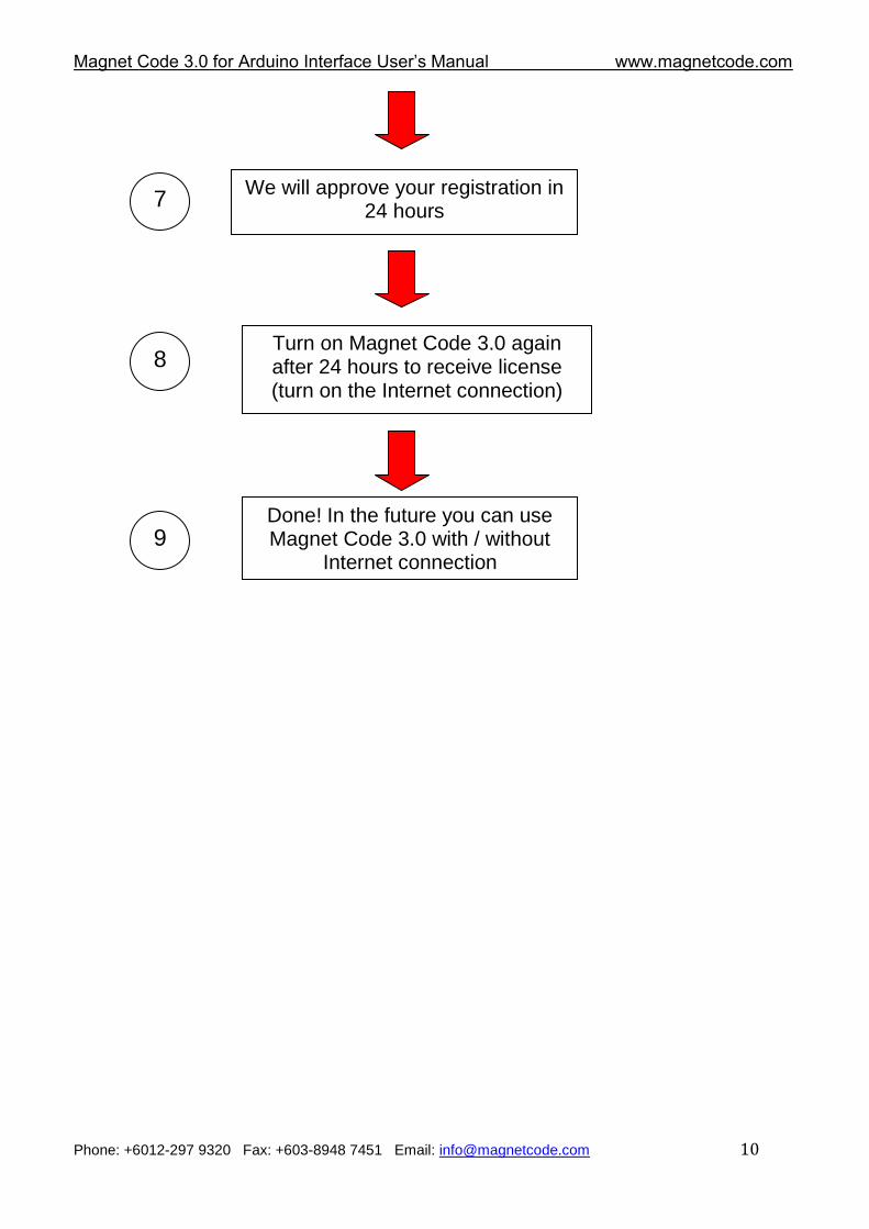
We will approve your registration in 24 hours
Turn on Magnet Code 3.0 again after 24 hours to receive license (turn on the Internet connection)
Done! In the future you can use Magnet Code 3.0 with / without
Internet connection
7
8
9
Magnet Code 3.0 for Arduino Interface User‟s Manual www.magnetcode.com
Phone: +6012-297 9320 Fax: +603-8948 7451 Email: [email protected] 11
Chapter 2 Graphical User Interface
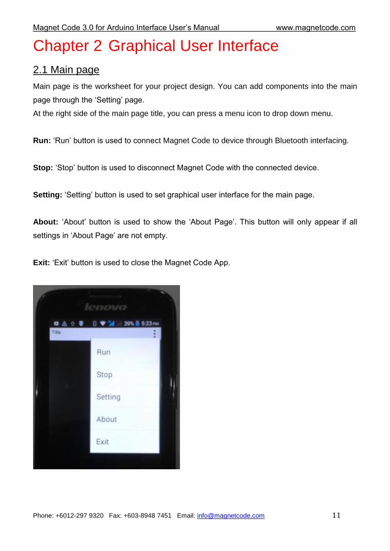
2.1 Main page
Main page is the worksheet for your project design. You can add components into the main
page through the „Setting‟ page.
At the right side of the main page title, you can press a menu icon to drop down menu.
Run: „Run‟ button is used to connect Magnet Code to device through Bluetooth interfacing.
Stop: „Stop‟ button is used to disconnect Magnet Code with the connected device.
Setting: „Setting‟ button is used to set graphical user interface for the main page.
About: „About‟ button is used to show the „About Page‟. This button will only appear if all
settings in „About Page‟ are not empty.
Exit: „Exit‟ button is used to close the Magnet Code App.
Magnet Code 3.0 for Arduino Interface User‟s Manual www.magnetcode.com
Phone: +6012-297 9320 Fax: +603-8948 7451 Email: [email protected] 12
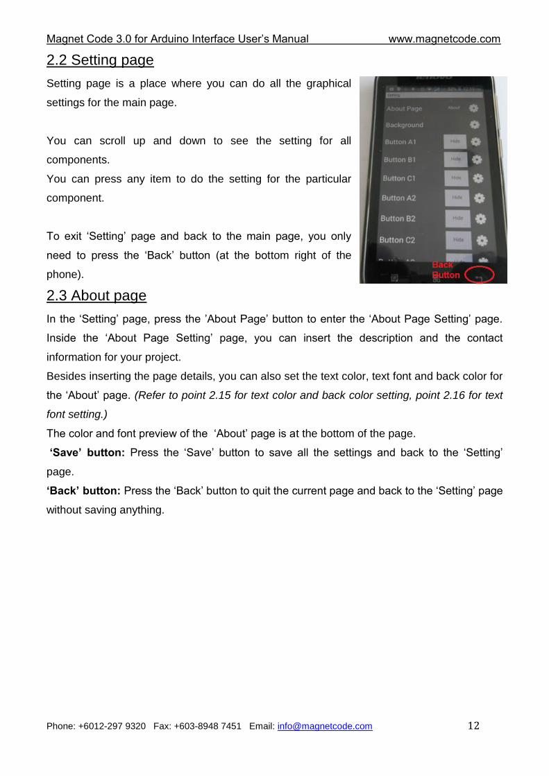
2.2 Setting page
Setting page is a place where you can do all the graphical
settings for the main page.
You can scroll up and down to see the setting for all
components.
You can press any item to do the setting for the particular
component.
To exit „Setting‟ page and back to the main page, you only
need to press the „Back‟ button (at the bottom right of the
phone).
2.3 About page
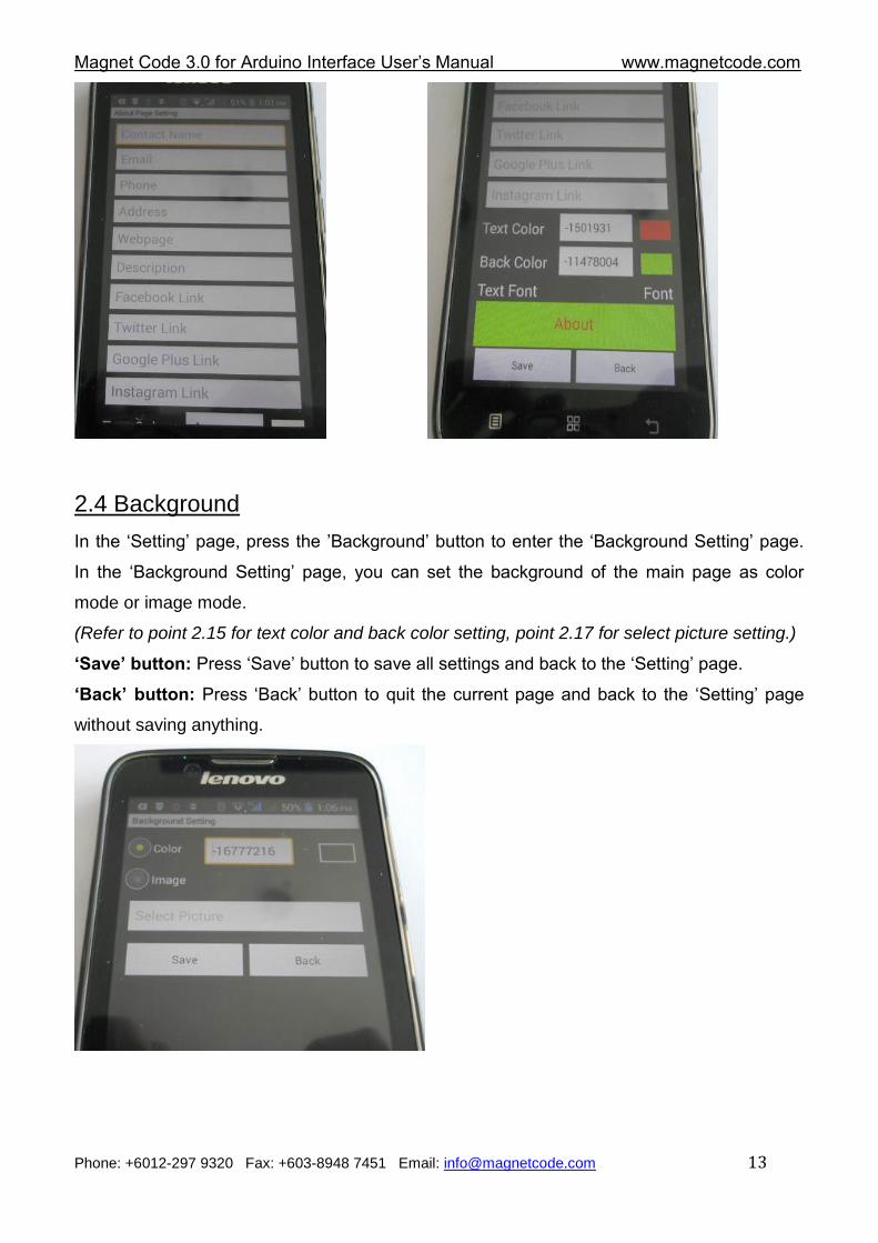
In the „Setting‟ page, press the ‟About Page‟ button to enter the „About Page Setting‟ page.
Inside the „About Page Setting‟ page, you can insert the description and the contact
information for your project.
Besides inserting the page details, you can also set the text color, text font and back color for
the „About‟ page. (Refer to point 2.15 for text color and back color setting, point 2.16 for text
font setting.)
The color and font preview of the „About‟ page is at the bottom of the page.
‘Save’ button: Press the „Save‟ button to save all the settings and back to the „Setting‟
page.
‘Back’ button: Press the „Back‟ button to quit the current page and back to the „Setting‟ page
without saving anything.
Magnet Code 3.0 for Arduino Interface User‟s Manual www.magnetcode.com
Phone: +6012-297 9320 Fax: +603-8948 7451 Email: [email protected] 13
2.4 Background
In the „Setting‟ page, press the ‟Background‟ button to enter the „Background Setting‟ page.
In the „Background Setting‟ page, you can set the background of the main page as color
mode or image mode.
(Refer to point 2.15 for text color and back color setting, point 2.17 for select picture setting.)
‘Save’ button: Press „Save‟ button to save all settings and back to the „Setting‟ page.
‘Back’ button: Press „Back‟ button to quit the current page and back to the „Setting‟ page
without saving anything.
Magnet Code 3.0 for Arduino Interface User‟s Manual www.magnetcode.com
Phone: +6012-297 9320 Fax: +603-8948 7451 Email: [email protected] 14
2.5 Button
There are 18 buttons in Magnet Code.
The buttons are arranged into 3 columns and 6 rows.
Row 1 with button A1, B1, C1
Row 2 with button A2, B2, C2
Row 3 with button A3, B3, C3
Row 4 with button A4, B4, C4
Row 5 with button A5, B5, C5
Row 6 with button A6, B6, C6
You can use button for output or input purpose.
You can press any button in the „Setting‟ page to access the button‟s setting page.
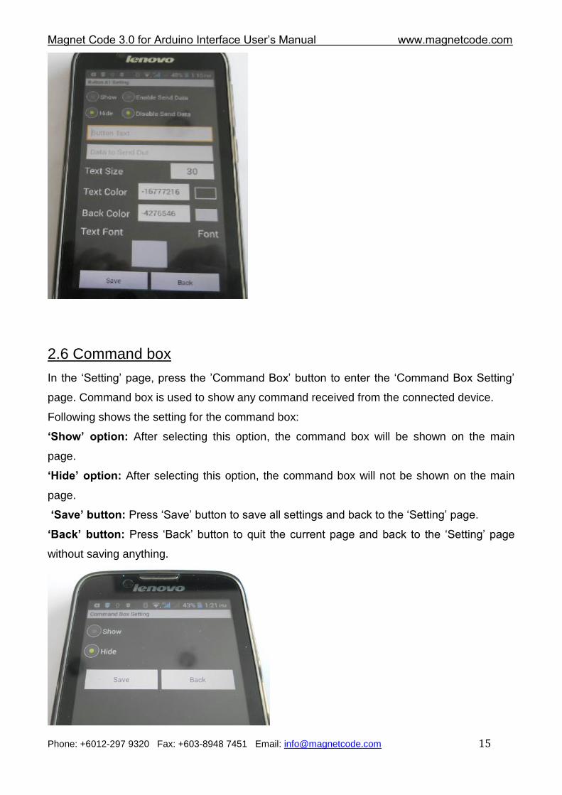
Following shows the setting for the buttons:
‘Show’ option: After selecting this option, the button will be shown on the main page.
‘Hide’ option: After selecting this option, the button will not be shown on the main page.
‘Enable Send Data’ option: After selecting this option, data will be sent once the button is
pressed.
‘Disable Send Data’ option: After selecting this option, data will not be sent when the button
is pressed.
‘Button Text’ textbox: The content in this textbox will be shown on the button when the
„Show‟ option is selected.
‘Data to Send Out’ textbox: The content in this textbox will be sent to the connected device
after the button is pressed.
You can also set text size, text color, text font and back color for the button.
(Refer to point 2.15 for text color and back color setting, point 2.16 for text font setting, point
2.18 for text size setting.)
The preview of the button is at the bottom of the page.
‘Save’ button: Press „Save‟ button to save all settings and back to the „Setting‟ page.
‘Back’ button: Press „Back‟ button to quit the current page and back to the „Setting‟ page
without saving anything.
Note:
The width of the button can be set to fixed width or dynamic width. Refer to point 2.9 for
details.
Magnet Code 3.0 for Arduino Interface User‟s Manual www.magnetcode.com
Phone: +6012-297 9320 Fax: +603-8948 7451 Email: [email protected] 15
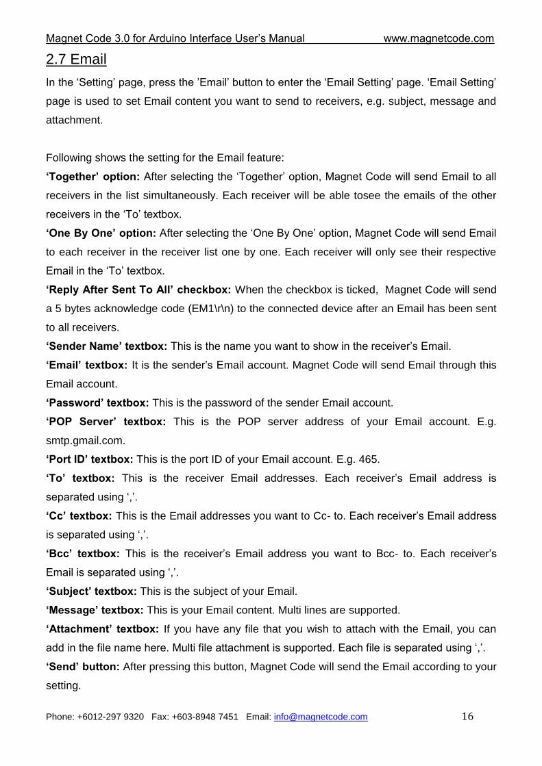
2.6 Command box
In the „Setting‟ page, press the ‟Command Box‟ button to enter the „Command Box Setting‟
page. Command box is used to show any command received from the connected device.
Following shows the setting for the command box:
‘Show’ option: After selecting this option, the command box will be shown on the main
page.
‘Hide’ option: After selecting this option, the command box will not be shown on the main
page.
‘Save’ button: Press „Save‟ button to save all settings and back to the „Setting‟ page.
‘Back’ button: Press „Back‟ button to quit the current page and back to the „Setting‟ page
without saving anything.
Magnet Code 3.0 for Arduino Interface User‟s Manual www.magnetcode.com
Phone: +6012-297 9320 Fax: +603-8948 7451 Email: [email protected] 16
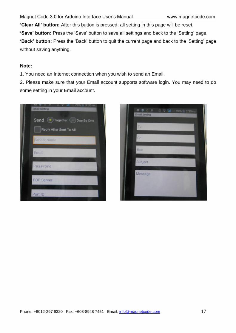
2.7 Email
In the „Setting‟ page, press the ‟Email‟ button to enter the „Email Setting‟ page. „Email Setting‟
page is used to set Email content you want to send to receivers, e.g. subject, message and
attachment.
Following shows the setting for the Email feature:
‘Together’ option: After selecting the „Together‟ option, Magnet Code will send Email to all
receivers in the list simultaneously. Each receiver will be able tosee the emails of the other
receivers in the „To‟ textbox.
‘One By One’ option: After selecting the „One By One‟ option, Magnet Code will send Email
to each receiver in the receiver list one by one. Each receiver will only see their respective
Email in the „To‟ textbox.
‘Reply After Sent To All’ checkbox: When the checkbox is ticked, Magnet Code will send
a 5 bytes acknowledge code (EM1\r\n) to the connected device after an Email has been sent
to all receivers.
‘Sender Name’ textbox: This is the name you want to show in the receiver‟s Email.
‘Email’ textbox: It is the sender‟s Email account. Magnet Code will send Email through this
Email account.
‘Password’ textbox: This is the password of the sender Email account.
‘POP Server’ textbox: This is the POP server address of your Email account. E.g.
smtp.gmail.com.
‘Port ID’ textbox: This is the port ID of your Email account. E.g. 465.
‘To’ textbox: This is the receiver Email addresses. Each receiver‟s Email address is
separated using „,‟.
‘Cc’ textbox: This is the Email addresses you want to Cc- to. Each receiver‟s Email address
is separated using „,‟.
‘Bcc’ textbox: This is the receiver‟s Email address you want to Bcc- to. Each receiver‟s
Email is separated using „,‟.
‘Subject’ textbox: This is the subject of your Email.
‘Message’ textbox: This is your Email content. Multi lines are supported.
‘Attachment’ textbox: If you have any file that you wish to attach with the Email, you can
add in the file name here. Multi file attachment is supported. Each file is separated using „,‟.
‘Send’ button: After pressing this button, Magnet Code will send the Email according to your
setting.
Magnet Code 3.0 for Arduino Interface User‟s Manual www.magnetcode.com
Phone: +6012-297 9320 Fax: +603-8948 7451 Email: [email protected] 17
‘Clear All’ button: After this button is pressed, all setting in this page will be reset.
‘Save’ button: Press the „Save‟ button to save all settings and back to the „Setting‟ page.
‘Back’ button: Press the „Back‟ button to quit the current page and back to the „Setting‟ page
without saving anything.
Note:
1. You need an Internet connection when you wish to send an Email.
2. Please make sure that your Email account supports software login. You may need to do
some setting in your Email account.
Magnet Code 3.0 for Arduino Interface User‟s Manual www.magnetcode.com
Phone: +6012-297 9320 Fax: +603-8948 7451 Email: [email protected] 18
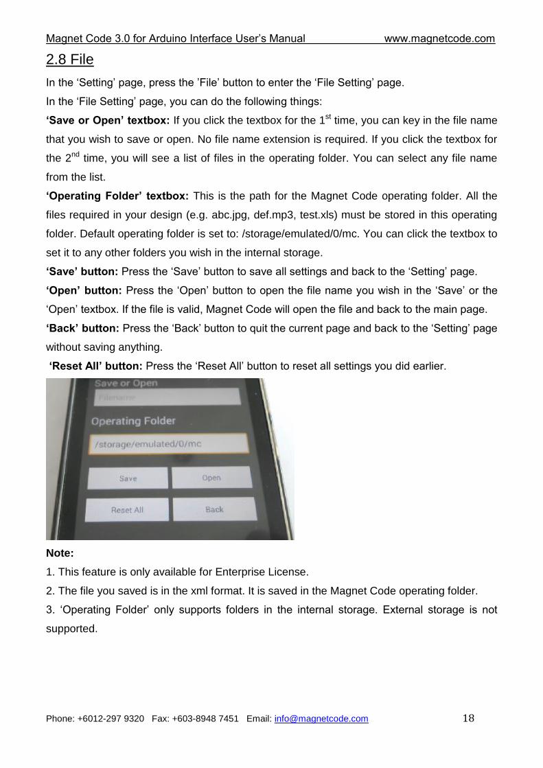
2.8 File
In the „Setting‟ page, press the ‟File‟ button to enter the „File Setting‟ page.
In the „File Setting‟ page, you can do the following things:
‘Save or Open’ textbox: If you click the textbox for the 1st time, you can key in the file name
that you wish to save or open. No file name extension is required. If you click the textbox for
the 2nd time, you will see a list of files in the operating folder. You can select any file name
from the list.
‘Operating Folder’ textbox: This is the path for the Magnet Code operating folder. All the
files required in your design (e.g. abc.jpg, def.mp3, test.xls) must be stored in this operating
folder. Default operating folder is set to: /storage/emulated/0/mc. You can click the textbox to
set it to any other folders you wish in the internal storage.
‘Save’ button: Press the „Save‟ button to save all settings and back to the „Setting‟ page.
‘Open’ button: Press the „Open‟ button to open the file name you wish in the „Save‟ or the
„Open‟ textbox. If the file is valid, Magnet Code will open the file and back to the main page.
‘Back’ button: Press the „Back‟ button to quit the current page and back to the „Setting‟ page
without saving anything.
‘Reset All’ button: Press the „Reset All‟ button to reset all settings you did earlier.
Note:
1. This feature is only available for Enterprise License.
2. The file you saved is in the xml format. It is saved in the Magnet Code operating folder.
3. „Operating Folder‟ only supports folders in the internal storage. External storage is not
supported.
Magnet Code 3.0 for Arduino Interface User‟s Manual www.magnetcode.com
Phone: +6012-297 9320 Fax: +603-8948 7451 Email: [email protected] 19
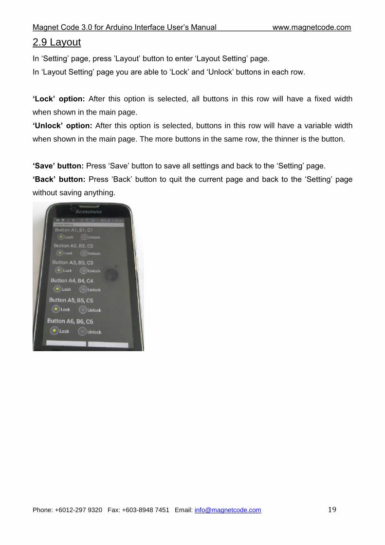
2.9 Layout
In „Setting‟ page, press ‟Layout‟ button to enter „Layout Setting‟ page.
In „Layout Setting‟ page you are able to „Lock‟ and „Unlock‟ buttons in each row.
‘Lock’ option: After this option is selected, all buttons in this row will have a fixed width
when shown in the main page.
‘Unlock’ option: After this option is selected, buttons in this row will have a variable width
when shown in the main page. The more buttons in the same row, the thinner is the button.
‘Save’ button: Press „Save‟ button to save all settings and back to the „Setting‟ page.
‘Back’ button: Press „Back‟ button to quit the current page and back to the „Setting‟ page
without saving anything.
Magnet Code 3.0 for Arduino Interface User‟s Manual www.magnetcode.com
Phone: +6012-297 9320 Fax: +603-8948 7451 Email: [email protected] 20
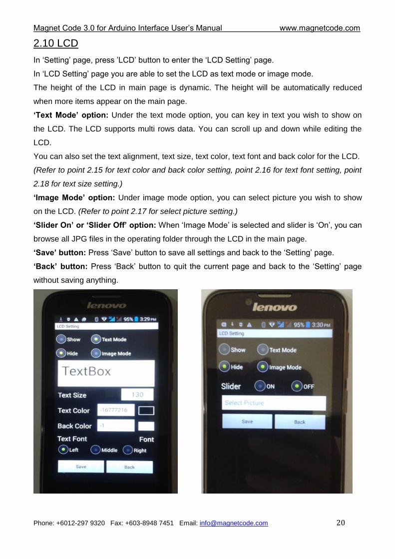
2.10 LCD
In „Setting‟ page, press ‟LCD‟ button to enter the „LCD Setting‟ page.
In „LCD Setting‟ page you are able to set the LCD as text mode or image mode.
The height of the LCD in main page is dynamic. The height will be automatically reduced
when more items appear on the main page.
‘Text Mode’ option: Under the text mode option, you can key in text you wish to show on
the LCD. The LCD supports multi rows data. You can scroll up and down while editing the
LCD.
You can also set the text alignment, text size, text color, text font and back color for the LCD.
(Refer to point 2.15 for text color and back color setting, point 2.16 for text font setting, point
2.18 for text size setting.)
‘Image Mode’ option: Under image mode option, you can select picture you wish to show
on the LCD. (Refer to point 2.17 for select picture setting.)
‘Slider On’ or ‘Slider Off’ option: When „Image Mode‟ is selected and slider is „On‟, you can
browse all JPG files in the operating folder through the LCD in the main page.
‘Save’ button: Press „Save‟ button to save all settings and back to the „Setting‟ page.
‘Back’ button: Press „Back‟ button to quit the current page and back to the „Setting‟ page
without saving anything.
Magnet Code 3.0 for Arduino Interface User‟s Manual www.magnetcode.com
Phone: +6012-297 9320 Fax: +603-8948 7451 Email: [email protected] 21
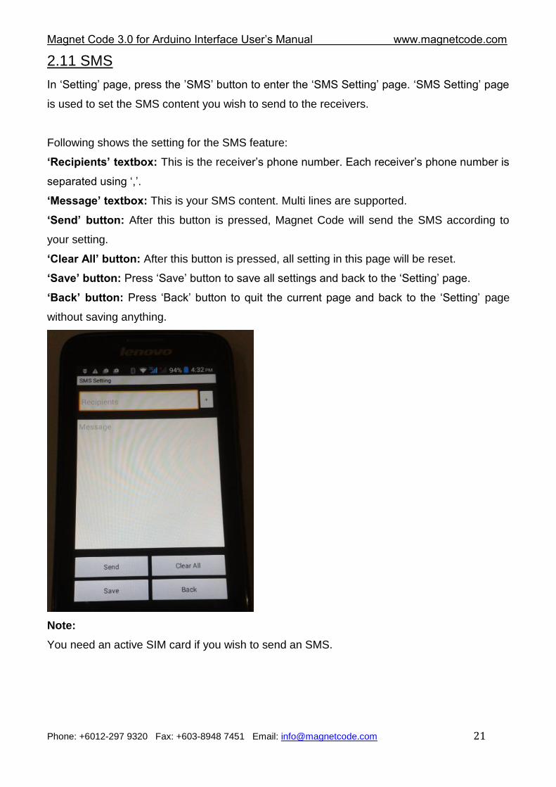
2.11 SMS
In „Setting‟ page, press the ‟SMS‟ button to enter the „SMS Setting‟ page. „SMS Setting‟ page
is used to set the SMS content you wish to send to the receivers.
Following shows the setting for the SMS feature:
‘Recipients’ textbox: This is the receiver‟s phone number. Each receiver‟s phone number is
separated using „,‟.
‘Message’ textbox: This is your SMS content. Multi lines are supported.
‘Send’ button: After this button is pressed, Magnet Code will send the SMS according to
your setting.
‘Clear All’ button: After this button is pressed, all setting in this page will be reset.
‘Save’ button: Press „Save‟ button to save all settings and back to the „Setting‟ page.
‘Back’ button: Press „Back‟ button to quit the current page and back to the „Setting‟ page
without saving anything.
Note:
You need an active SIM card if you wish to send an SMS.
Magnet Code 3.0 for Arduino Interface User‟s Manual www.magnetcode.com
Phone: +6012-297 9320 Fax: +603-8948 7451 Email: [email protected] 22
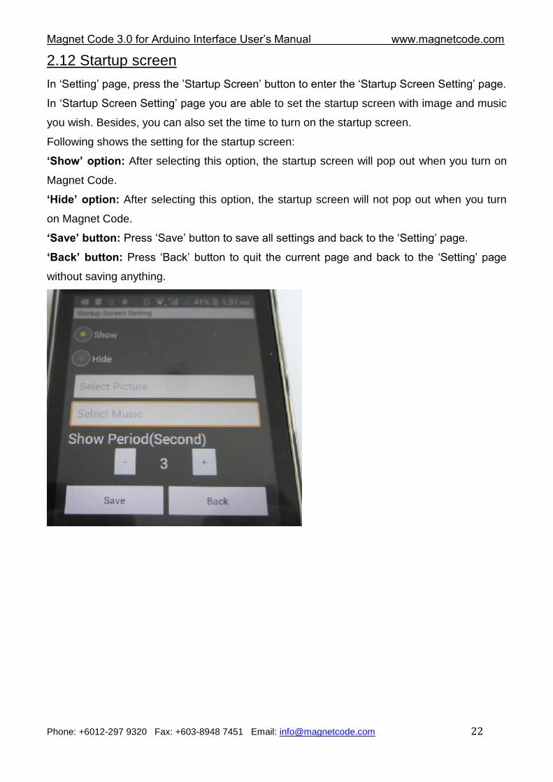
2.12 Startup screen
In „Setting‟ page, press the ‟Startup Screen‟ button to enter the „Startup Screen Setting‟ page.
In „Startup Screen Setting‟ page you are able to set the startup screen with image and music
you wish. Besides, you can also set the time to turn on the startup screen.
Following shows the setting for the startup screen:
‘Show’ option: After selecting this option, the startup screen will pop out when you turn on
Magnet Code.
‘Hide’ option: After selecting this option, the startup screen will not pop out when you turn
on Magnet Code.
‘Save’ button: Press „Save‟ button to save all settings and back to the „Setting‟ page.
‘Back’ button: Press „Back‟ button to quit the current page and back to the „Setting‟ page
without saving anything.
Magnet Code 3.0 for Arduino Interface User‟s Manual www.magnetcode.com
Phone: +6012-297 9320 Fax: +603-8948 7451 Email: [email protected] 23
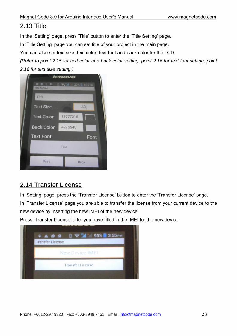
2.13 Title
In the „Setting‟ page, press ‟Title‟ button to enter the „Title Setting‟ page.
In „Title Setting‟ page you can set title of your project in the main page.
You can also set text size, text color, text font and back color for the LCD.
(Refer to point 2.15 for text color and back color setting, point 2.16 for text font setting, point
2.18 for text size setting.)
2.14 Transfer License
In „Setting‟ page, press the ‟Transfer License‟ button to enter the „Transfer License‟ page.
In „Transfer License‟ page you are able to transfer the license from your current device to the
new device by inserting the new IMEI of the new device.
Press „Transfer License‟ after you have filled in the IMEI for the new device.
Magnet Code 3.0 for Arduino Interface User‟s Manual www.magnetcode.com
Phone: +6012-297 9320 Fax: +603-8948 7451 Email: [email protected] 24
Note:
1. You need to contact us to enable this license transfer when you wish to transfer the
license to the new device.
2. You need an Internet connection when you wish to transfer the license.
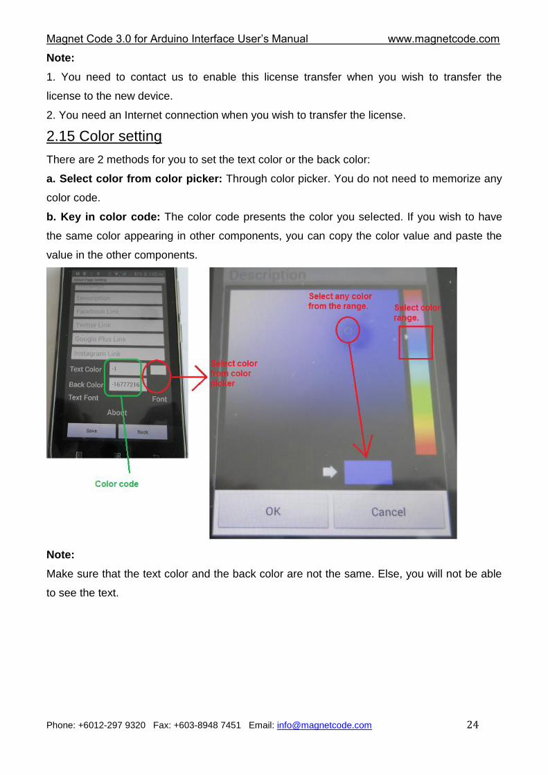
2.15 Color setting
There are 2 methods for you to set the text color or the back color:
a. Select color from color picker: Through color picker. You do not need to memorize any
color code.
b. Key in color code: The color code presents the color you selected. If you wish to have
the same color appearing in other components, you can copy the color value and paste the
value in the other components.
Note:
Make sure that the text color and the back color are not the same. Else, you will not be able
to see the text.
Magnet Code 3.0 for Arduino Interface User‟s Manual www.magnetcode.com
Phone: +6012-297 9320 Fax: +603-8948 7451 Email: [email protected] 25
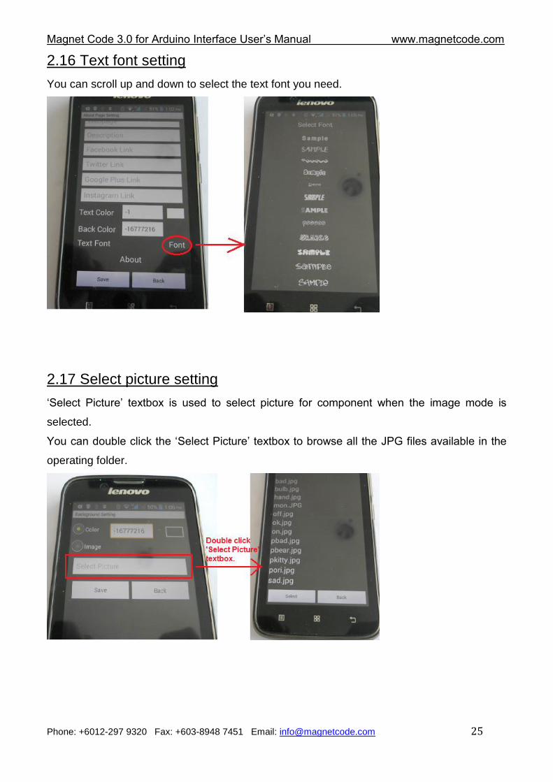
2.16 Text font setting
You can scroll up and down to select the text font you need.
2.17 Select picture setting
„Select Picture‟ textbox is used to select picture for component when the image mode is
selected.
You can double click the „Select Picture‟ textbox to browse all the JPG files available in the
operating folder.
Magnet Code 3.0 for Arduino Interface User‟s Manual www.magnetcode.com
Phone: +6012-297 9320 Fax: +603-8948 7451 Email: [email protected] 26
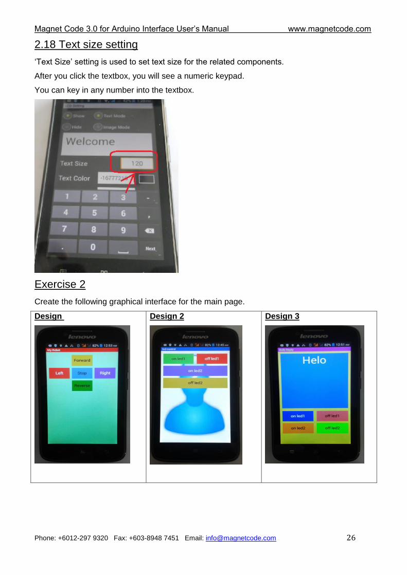
2.18 Text size setting
„Text Size‟ setting is used to set text size for the related components.
After you click the textbox, you will see a numeric keypad.
You can key in any number into the textbox.
Exercise 2
Create the following graphical interface for the main page.
Design
Design 2
Design 3
Magnet Code 3.0 for Arduino Interface User‟s Manual www.magnetcode.com
Phone: +6012-297 9320 Fax: +603-8948 7451 Email: [email protected] 27
Chapter 3 Getting Started
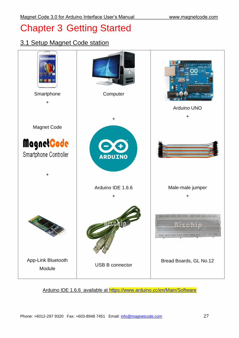
3.1 Setup Magnet Code station
Smartphone
+
Magnet Code
+
App-Link Bluetooth
Module
Computer
+
Arduino IDE 1.6.6
+
USB B connector
Arduino UNO
+
Male-male jumper
+
Bread Boards, GL No.12
Arduino IDE 1.6.6 available at https://www.arduino.cc/en/Main/Software
Magnet Code 3.0 for Arduino Interface User‟s Manual www.magnetcode.com
Phone: +6012-297 9320 Fax: +603-8948 7451 Email: [email protected] 28
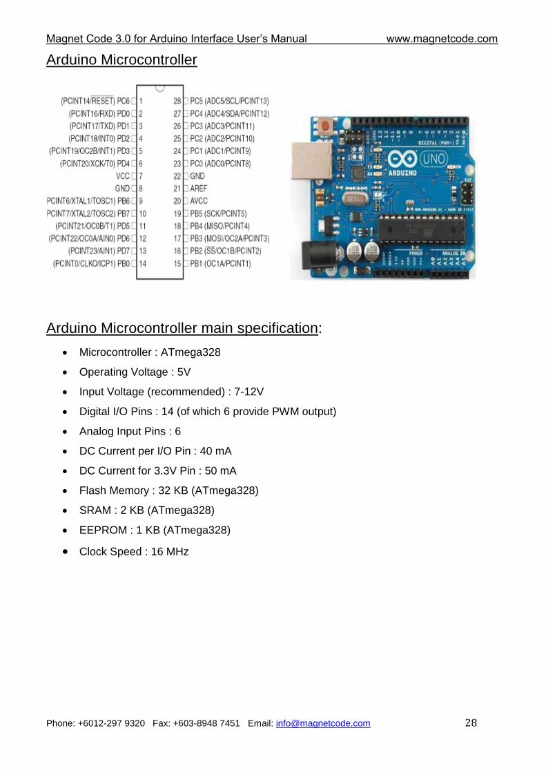
Arduino Microcontroller
Arduino Microcontroller main specification:
Microcontroller : ATmega328
Operating Voltage : 5V
Input Voltage (recommended) : 7-12V
Digital I/O Pins : 14 (of which 6 provide PWM output)
Analog Input Pins : 6
DC Current per I/O Pin : 40 mA
DC Current for 3.3V Pin : 50 mA
Flash Memory : 32 KB (ATmega328)
SRAM : 2 KB (ATmega328)
EEPROM : 1 KB (ATmega328)
Clock Speed : 16 MHz
Magnet Code 3.0 for Arduino Interface User‟s Manual www.magnetcode.com
Phone: +6012-297 9320 Fax: +603-8948 7451 Email: [email protected] 29
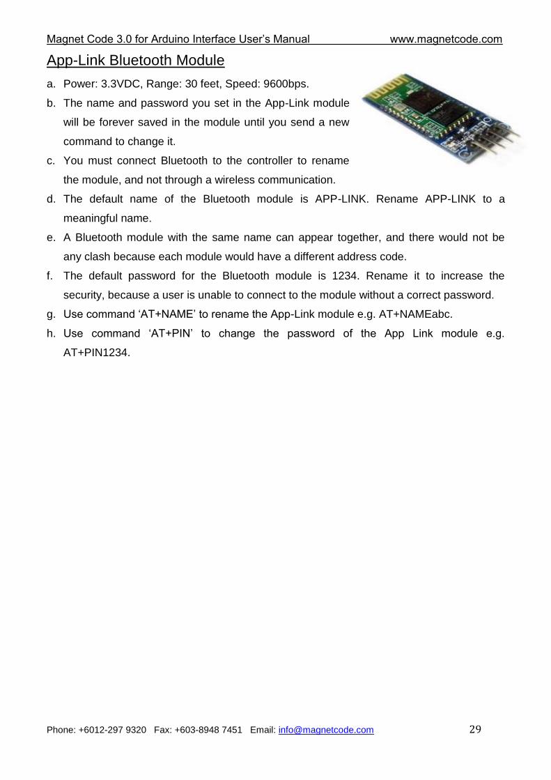
App-Link Bluetooth Module
a. Power: 3.3VDC, Range: 30 feet, Speed: 9600bps.
b. The name and password you set in the App-Link module
will be forever saved in the module until you send a new
command to change it.
c. You must connect Bluetooth to the controller to rename
the module, and not through a wireless communication.
d. The default name of the Bluetooth module is APP-LINK. Rename APP-LINK to a
meaningful name.
e. A Bluetooth module with the same name can appear together, and there would not be
any clash because each module would have a different address code.
f. The default password for the Bluetooth module is 1234. Rename it to increase the
security, because a user is unable to connect to the module without a correct password.
g. Use command „AT+NAME‟ to rename the App-Link module e.g. AT+NAMEabc.
h. Use command „AT+PIN‟ to change the password of the App Link module e.g.
AT+PIN1234.
Magnet Code 3.0 for Arduino Interface User‟s Manual www.magnetcode.com
Phone: +6012-297 9320 Fax: +603-8948 7451 Email: [email protected] 30
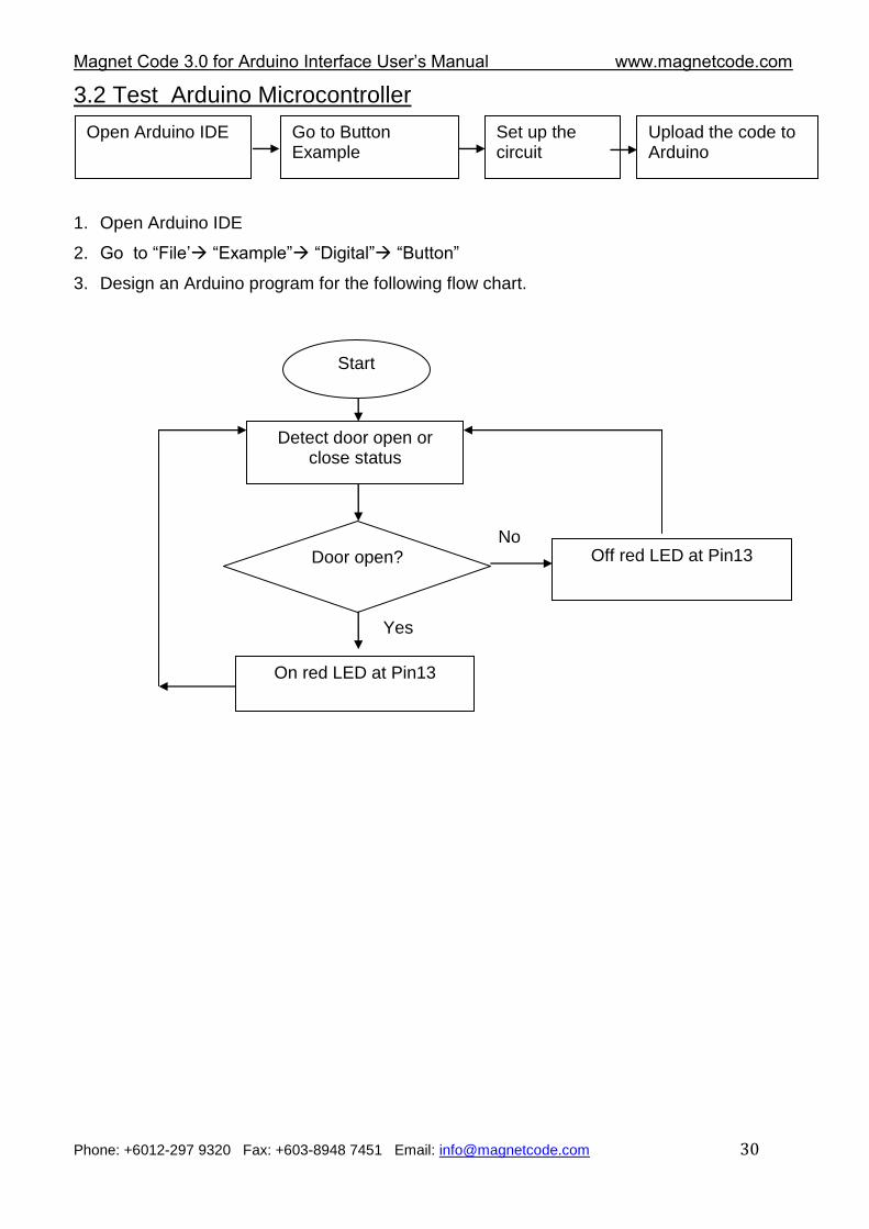
3.2 Test Arduino Microcontroller
1. Open Arduino IDE
2. Go to “File‟ “Example” “Digital” “Button”
3. Design an Arduino program for the following flow chart.
Open Arduino IDE Go to Button Example
Set up the circuit
Upload the code to Arduino
Start
Detect door open or close status
Door open? No
Yes
Off red LED at Pin13
On red LED at Pin13
Magnet Code 3.0 for Arduino Interface User‟s Manual www.magnetcode.com
Phone: +6012-297 9320 Fax: +603-8948 7451 Email: [email protected] 31
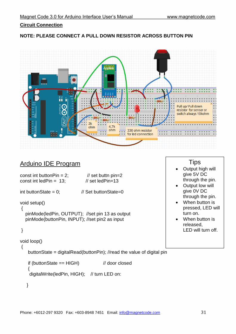
Circuit Connection NOTE: PLEASE CONNECT A PULL DOWN RESISTOR ACROSS BUTTON PIN
Arduino IDE Program const int buttonPin = 2; // set buttn pin=2 const int ledPin = 13; // set ledPin=13 int buttonState = 0; // Set buttonState=0 void setup() { pinMode(ledPin, OUTPUT); //set pin 13 as output pinMode(buttonPin, INPUT); //set pin2 as input } void loop() { buttonState = digitalRead(buttonPin); //read the value of digital pin if (buttonState == HIGH) // door closed {
digitalWrite(ledPin, HIGH); // turn LED on:
}
Tips Output high will
give 5V DC through the pin.
Output low will give 0V DC through the pin.
When button is pressed, LED will turn on.
When button is released, LED will turn off.
Magnet Code 3.0 for Arduino Interface User‟s Manual www.magnetcode.com
Phone: +6012-297 9320 Fax: +603-8948 7451 Email: [email protected] 32
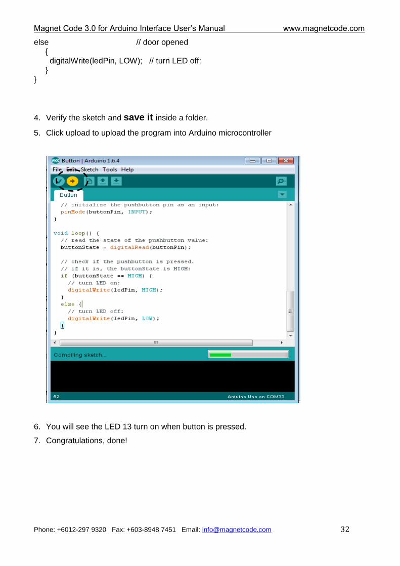
else // door opened { digitalWrite(ledPin, LOW); // turn LED off: } }
4. Verify the sketch and save it inside a folder.
5. Click upload to upload the program into Arduino microcontroller
6. You will see the LED 13 turn on when button is pressed.
7. Congratulations, done!
Magnet Code 3.0 for Arduino Interface User‟s Manual www.magnetcode.com
Phone: +6012-297 9320 Fax: +603-8948 7451 Email: [email protected] 33
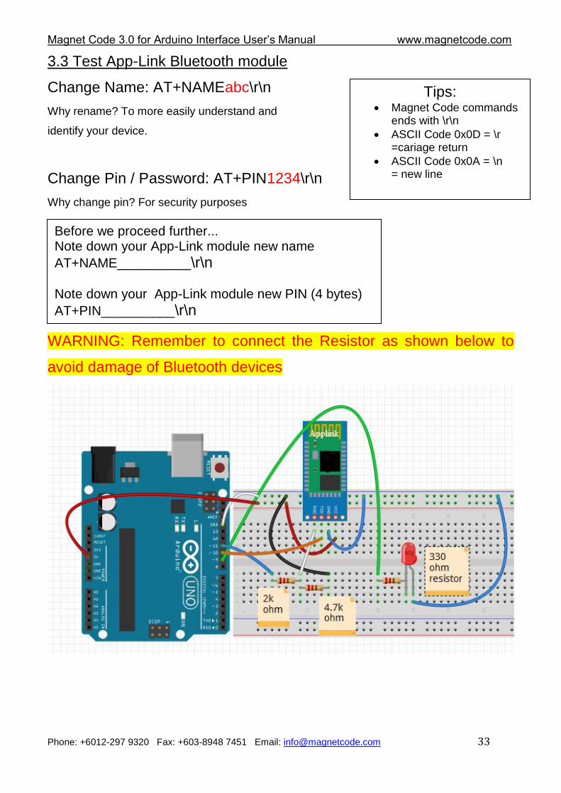
3.3 Test App-Link Bluetooth module
Change Name: AT+NAMEabc\r\n
Why rename? To more easily understand and
identify your device.
Change Pin / Password: AT+PIN1234\r\n
Why change pin? For security purposes
WARNING: Remember to connect the Resistor as shown below to
avoid damage of Bluetooth devices
Before we proceed further... Note down your App-Link module new name
AT+NAME__________\r\n
Note down your App-Link module new PIN (4 bytes)
AT+PIN__________\r\n
Tips: Magnet Code commands
ends with \r\n
ASCII Code 0x0D = \r =cariage return
ASCII Code 0x0A = \n = new line
Magnet Code 3.0 for Arduino Interface User‟s Manual www.magnetcode.com
Phone: +6012-297 9320 Fax: +603-8948 7451 Email: [email protected] 34
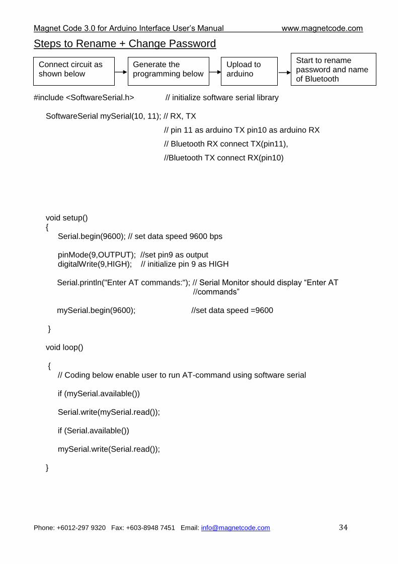
Steps to Rename + Change Password
#include <SoftwareSerial.h> // initialize software serial library
SoftwareSerial mySerial(10, 11); // RX, TX
// pin 11 as arduino TX pin10 as arduino RX
// Bluetooth RX connect TX(pin11),
//Bluetooth TX connect RX(pin10)
void setup() {
Serial.begin(9600); // set data speed 9600 bps
pinMode(9,OUTPUT); //set pin9 as output digitalWrite(9,HIGH); // initialize pin 9 as HIGH
Serial.println("Enter AT commands:"); // Serial Monitor should display “Enter AT //commands” mySerial.begin(9600); //set data speed =9600 } void loop() {
// Coding below enable user to run AT-command using software serial
if (mySerial.available())
Serial.write(mySerial.read());
if (Serial.available())
mySerial.write(Serial.read()); }
Connect circuit as shown below
Generate the programming below
Upload to arduino
Start to rename password and name of Bluetooth
Magnet Code 3.0 for Arduino Interface User‟s Manual www.magnetcode.com
Phone: +6012-297 9320 Fax: +603-8948 7451 Email: [email protected] 35
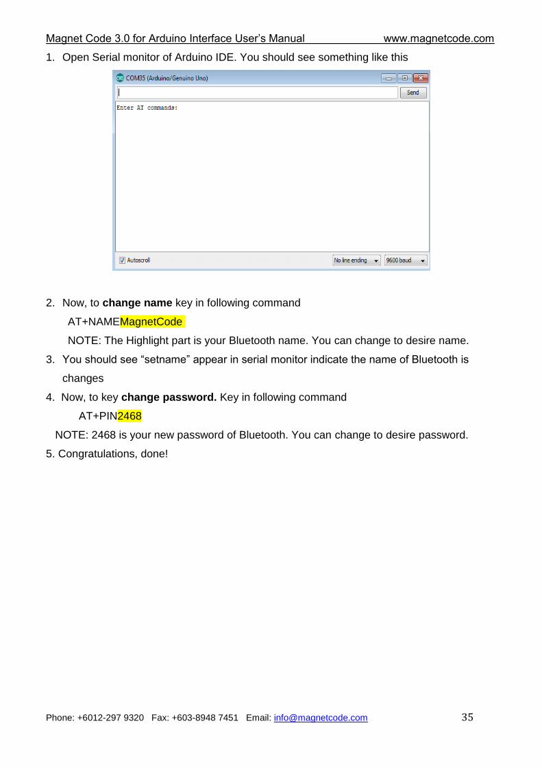
1. Open Serial monitor of Arduino IDE. You should see something like this
2. Now, to change name key in following command
AT+NAMEMagnetCode
NOTE: The Highlight part is your Bluetooth name. You can change to desire name.
3. You should see “setname” appear in serial monitor indicate the name of Bluetooth is
changes
4. Now, to key change password. Key in following command
AT+PIN2468
NOTE: 2468 is your new password of Bluetooth. You can change to desire password.
5. Congratulations, done!
Magnet Code 3.0 for Arduino Interface User‟s Manual www.magnetcode.com
Phone: +6012-297 9320 Fax: +603-8948 7451 Email: [email protected] 36
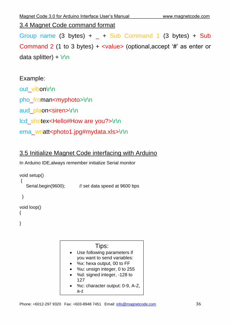
3.4 Magnet Code command format
Group name (3 bytes) + _ + Sub Command 1 (3 bytes) + Sub
Command 2 (1 to 3 bytes) + <value> (optional,accept „#‟ as enter or
data splitter) + \r\n
Example:
out_vibon\r\n
pho_froman<myphoto>\r\n
aud_plaon<siren>\r\n
lcd_shotex<Hello#How are you?>\r\n
ema_wriatt<photo1.jpg#mydata.xls>\r\n
3.5 Initialize Magnet Code interfacing with Arduino
In Arduino IDE,always remember initialize Serial monitor
void setup() { Serial.begin(9600); // set data speed at 9600 bps } void loop() { }
Tips: Use following parameters if
you want to send variables:
%x: hexa output, 00 to FF
%u: unsign integer, 0 to 255
%d: signed integer, -128 to 127
%c: character output: 0-9, A-Z, a-z
%lu: unsign long integer, 0 to 65535
Magnet Code 3.0 for Arduino Interface User‟s Manual www.magnetcode.com
Phone: +6012-297 9320 Fax: +603-8948 7451 Email: [email protected] 37
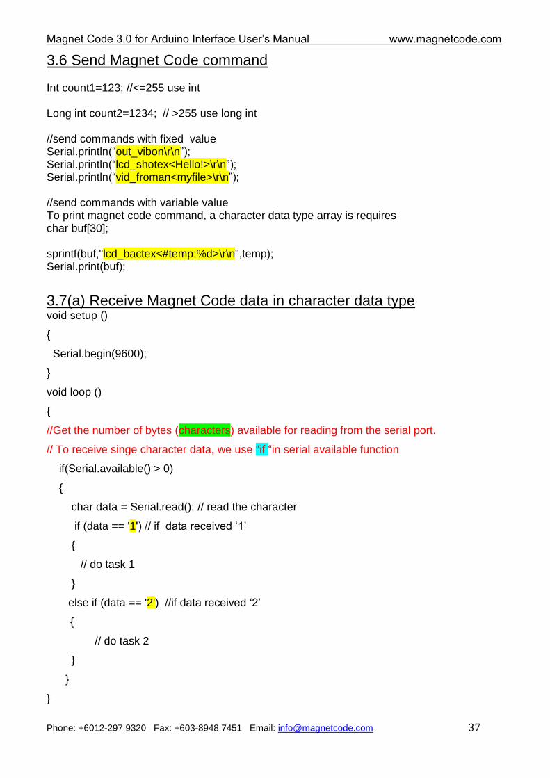
3.6 Send Magnet Code command Int count1=123; //<=255 use int Long int count2=1234; // >255 use long int //send commands with fixed value Serial.println(“out_vibon\r\n”); Serial.println(“lcd_shotex<Hello!>\r\n”); Serial.println(“vid_froman<myfile>\r\n”); //send commands with variable value To print magnet code command, a character data type array is requires char buf[30]; sprintf(buf,"lcd_bactex<#temp:%d>\r\n",temp); Serial.print(buf);
3.7(a) Receive Magnet Code data in character data type void setup ()
{
Serial.begin(9600);
}
void loop ()
{
//Get the number of bytes (characters) available for reading from the serial port.
// To receive singe character data, we use “if “in serial available function
if(Serial.available() > 0)
{
char data = Serial.read(); // read the character
if (data == '1') // if data received „1‟
{
// do task 1
}
else if (data == '2') //if data received „2‟
{
// do task 2
}
}
}
Magnet Code 3.0 for Arduino Interface User‟s Manual www.magnetcode.com
Phone: +6012-297 9320 Fax: +603-8948 7451 Email: [email protected] 38
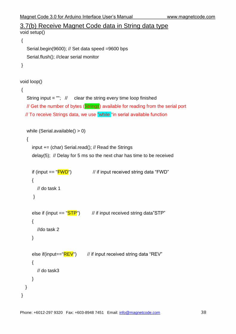
3.7(b) Receive Magnet Code data in String data type void setup()
{
Serial.begin(9600); // Set data speed =9600 bps
Serial.flush(); //clear serial monitor
}
void loop()
{
String input = ""; // clear the string every time loop finished
// Get the number of bytes (Strings) available for reading from the serial port
// To receive Strings data, we use “while “in serial available function
while (Serial.available() > 0)
{
input += (char) Serial.read(); // Read the Strings
delay(5); // Delay for 5 ms so the next char has time to be received
if (input == "FWD") // if input received string data “FWD”
{
// do task 1
}
else if (input == "STP") // if input received string data”STP”
{
//do task 2
}
else if(input=="REV") // if input received string data “REV”
{
// do task3
}
}
}
Magnet Code 3.0 for Arduino Interface User‟s Manual www.magnetcode.com
Phone: +6012-297 9320 Fax: +603-8948 7451 Email: [email protected] 39
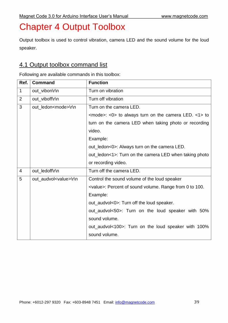
Chapter 4 Output Toolbox
Output toolbox is used to control vibration, camera LED and the sound volume for the loud
speaker.
4.1 Output toolbox command list
Following are available commands in this toolbox:
Ref. Command Function
1 out_vibon\r\n Turn on vibration
2 out_viboff\r\n Turn off vibration
3 out_ledon<mode>\r\n Turn on the camera LED.
<mode>: <0> to always turn on the camera LED. <1> to
turn on the camera LED when taking photo or recording
video.
Example:
out_ledon<0>: Always turn on the camera LED.
out_ledon<1>: Turn on the camera LED when taking photo
or recording video.
4 out_ledoff\r\n Turn off the camera LED.
5 out_audvol<value>\r\n Control the sound volume of the loud speaker
<value>: Percent of sound volume. Range from 0 to 100.
Example:
out_audvol<0>: Turn off the loud speaker.
out_audvol<50>: Turn on the loud speaker with 50%
sound volume.
out_audvol<100>: Turn on the loud speaker with 100%
sound volume.
Magnet Code 3.0 for Arduino Interface User‟s Manual www.magnetcode.com
Phone: +6012-297 9320 Fax: +603-8948 7451 Email: [email protected] 40
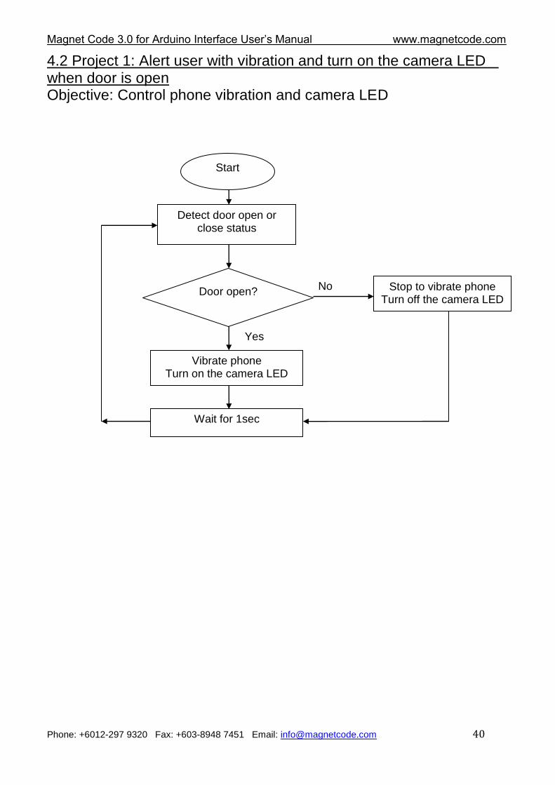
4.2 Project 1: Alert user with vibration and turn on the camera LED when door is open Objective: Control phone vibration and camera LED
Start
Detect door open or close status
Door open? No
Yes
Wait for 1sec
Vibrate phone Turn on the camera LED
Stop to vibrate phone Turn off the camera LED
Magnet Code 3.0 for Arduino Interface User‟s Manual www.magnetcode.com
Phone: +6012-297 9320 Fax: +603-8948 7451 Email: [email protected] 41
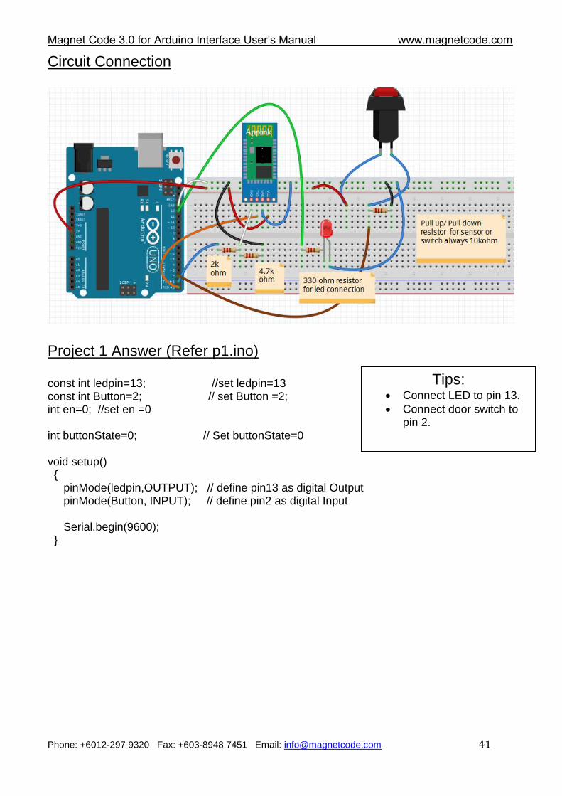
Circuit Connection
Project 1 Answer (Refer p1.ino) const int ledpin=13; //set ledpin=13 const int Button=2; // set Button =2; int en=0; //set en =0 int buttonState=0; // Set buttonState=0 void setup() { pinMode(ledpin,OUTPUT); // define pin13 as digital Output pinMode(Button, INPUT); // define pin2 as digital Input Serial.begin(9600); }
Tips: Connect LED to pin 13.
Connect door switch to pin 2.
Magnet Code 3.0 for Arduino Interface User‟s Manual www.magnetcode.com
Phone: +6012-297 9320 Fax: +603-8948 7451 Email: [email protected] 42
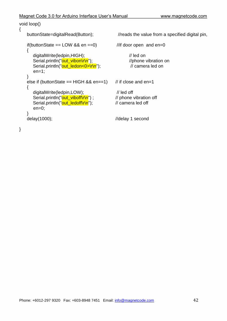
void loop() { buttonState=digitalRead(Button); //reads the value from a specified digital pin, if(buttonState == LOW && en ==0) //if door open and en=0 { digitalWrite(ledpin,HIGH); // led on Serial.println("out_vibon\r\n"); //phone vibration on Serial.println("out_ledon<0>\r\n"); // camera led on en=1; } else if (buttonState == HIGH && en==1) // if close and en=1 { digitalWrite(ledpin,LOW); // led off Serial.println("out_viboff\r\n") ; // phone vibration off Serial.println("out_ledoff\r\n"); // camera led off en=0; } delay(1000); //delay 1 second }
Magnet Code 3.0 for Arduino Interface User‟s Manual www.magnetcode.com
Phone: +6012-297 9320 Fax: +603-8948 7451 Email: [email protected] 43
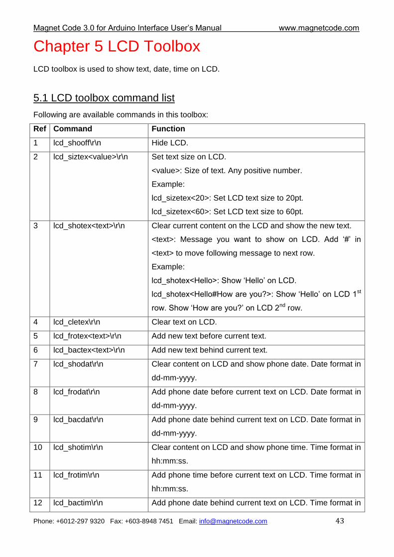
Chapter 5 LCD Toolbox
LCD toolbox is used to show text, date, time on LCD.
5.1 LCD toolbox command list
Following are available commands in this toolbox:
Ref Command Function
1 lcd_shooff\r\n Hide LCD.
2 lcd_siztex<value>\r\n Set text size on LCD.
<value>: Size of text. Any positive number.
Example:
lcd_sizetex<20>: Set LCD text size to 20pt.
lcd_sizetex<60>: Set LCD text size to 60pt.
3 lcd_shotex<text>\r\n Clear current content on the LCD and show the new text.
<text>: Message you want to show on LCD. Add „#‟ in
<text> to move following message to next row.
Example:
lcd_shotex<Hello>: Show „Hello‟ on LCD.
lcd_shotex<Hello#How are you?>: Show „Hello‟ on LCD 1st
row. Show „How are you?‟ on LCD 2nd row.
4 lcd_cletex\r\n Clear text on LCD.
5 lcd_frotex<text>\r\n Add new text before current text.
6 lcd_bactex<text>\r\n Add new text behind current text.
7 lcd_shodat\r\n Clear content on LCD and show phone date. Date format in
dd-mm-yyyy.
8 lcd_frodat\r\n Add phone date before current text on LCD. Date format in
dd-mm-yyyy.
9 lcd_bacdat\r\n Add phone date behind current text on LCD. Date format in
dd-mm-yyyy.
10 lcd_shotim\r\n Clear content on LCD and show phone time. Time format in
hh:mm:ss.
11 lcd_frotim\r\n Add phone time before current text on LCD. Time format in
hh:mm:ss.
12 lcd_bactim\r\n Add phone date behind current text on LCD. Time format in
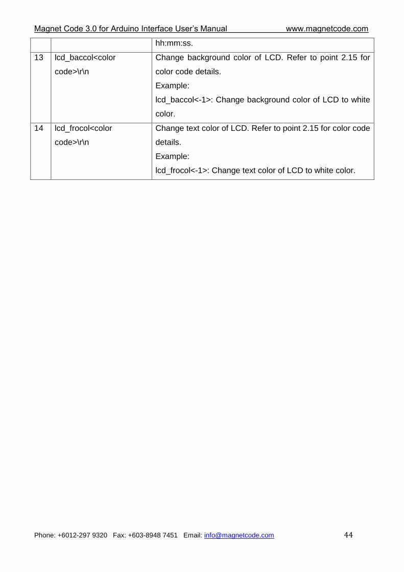
Magnet Code 3.0 for Arduino Interface User‟s Manual www.magnetcode.com
Phone: +6012-297 9320 Fax: +603-8948 7451 Email: [email protected] 44
hh:mm:ss.
13 lcd_baccol<color
code>\r\n
Change background color of LCD. Refer to point 2.15 for
color code details.
Example:
lcd_baccol<-1>: Change background color of LCD to white
color.
14 lcd_frocol<color
code>\r\n
Change text color of LCD. Refer to point 2.15 for color code
details.
Example:
lcd_frocol<-1>: Change text color of LCD to white color.
Magnet Code 3.0 for Arduino Interface User‟s Manual www.magnetcode.com
Phone: +6012-297 9320 Fax: +603-8948 7451 Email: [email protected] 45
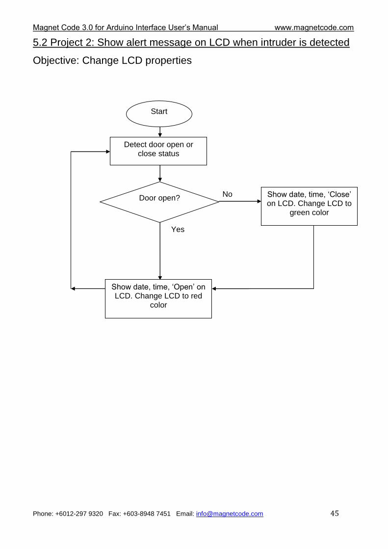
5.2 Project 2: Show alert message on LCD when intruder is detected
Objective: Change LCD properties
Start
Detect door open or close status
Door open? No
Yes
Show date, time, „Open‟ on LCD. Change LCD to red
color
Show date, time, „Close‟ on LCD. Change LCD to
green color
Magnet Code 3.0 for Arduino Interface User‟s Manual www.magnetcode.com
Phone: +6012-297 9320 Fax: +603-8948 7451 Email: [email protected] 46
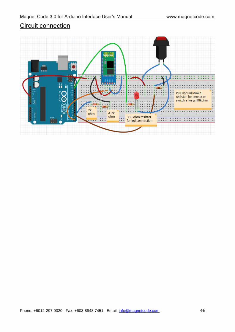
Circuit connection
Magnet Code 3.0 for Arduino Interface User‟s Manual www.magnetcode.com
Phone: +6012-297 9320 Fax: +603-8948 7451 Email: [email protected] 47
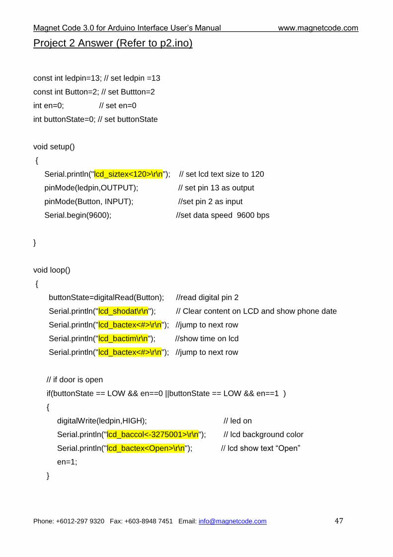
Project 2 Answer (Refer to p2.ino)
const int ledpin=13; // set ledpin =13
const int Button=2; // set Buttton=2
int en=0; // set en=0
int buttonState=0; // set buttonState
void setup()
{
Serial.println("lcd_siztex<120>\r\n"); // set lcd text size to 120
pinMode(ledpin,OUTPUT); // set pin 13 as output
pinMode(Button, INPUT); //set pin 2 as input
Serial.begin(9600); //set data speed 9600 bps
}
void loop()
{
buttonState=digitalRead(Button); //read digital pin 2
Serial.println("lcd_shodat\r\n"); // Clear content on LCD and show phone date
Serial.println("lcd_bactex<#>\r\n"); //jump to next row
Serial.println("lcd_bactim\r\n"); //show time on lcd
Serial.println("lcd_bactex<#>\r\n"); //jump to next row
// if door is open
if(buttonState == LOW && en==0 ||buttonState == LOW && en==1 )
{
digitalWrite(ledpin,HIGH); // led on
Serial.println("lcd_baccol<-3275001>\r\n"); // lcd background color
Serial.println("lcd_bactex<Open>\r\n"); // lcd show text “Open”
en=1;
}
Magnet Code 3.0 for Arduino Interface User‟s Manual www.magnetcode.com
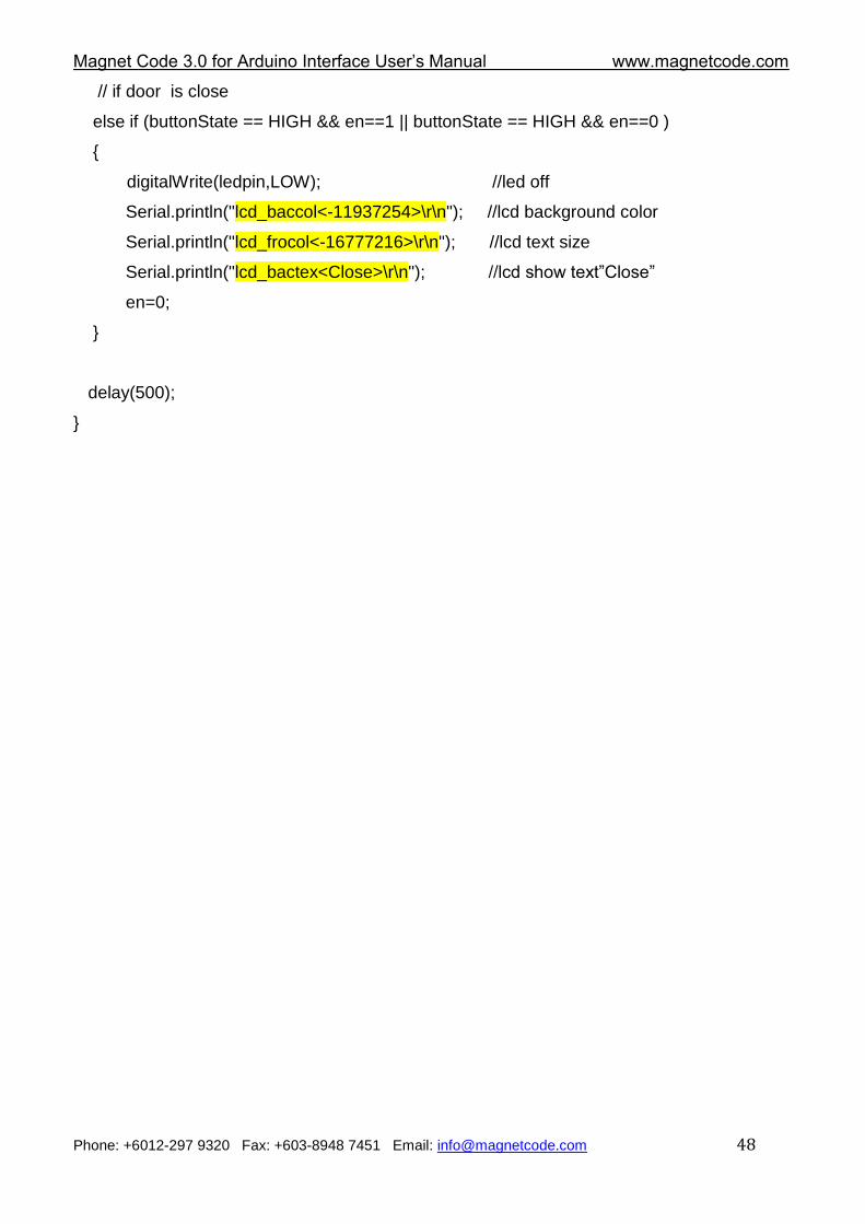
Phone: +6012-297 9320 Fax: +603-8948 7451 Email: [email protected] 48
// if door is close
else if (buttonState == HIGH && en==1 || buttonState == HIGH && en==0 )
{
digitalWrite(ledpin,LOW); //led off
Serial.println("lcd_baccol<-11937254>\r\n"); //lcd background color
Serial.println("lcd_frocol<-16777216>\r\n"); //lcd text size
Serial.println("lcd_bactex<Close>\r\n"); //lcd show text”Close”
en=0;
}
delay(500);
}
Magnet Code 3.0 for Arduino Interface User‟s Manual www.magnetcode.com
Phone: +6012-297 9320 Fax: +603-8948 7451 Email: [email protected] 49
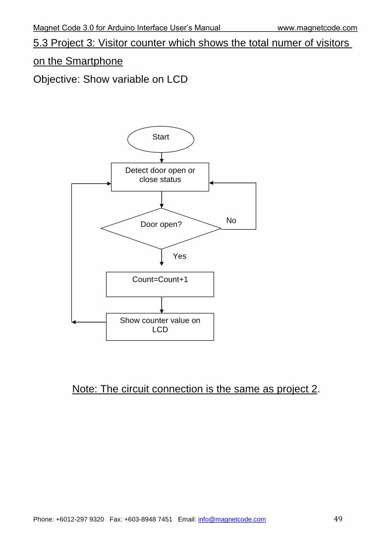
5.3 Project 3: Visitor counter which shows the total numer of visitors
on the Smartphone
Objective: Show variable on LCD
Note: The circuit connection is the same as project 2.
Start
Detect door open or close status
Door open? No
Yes
Show counter value on LCD
Count=Count+1
Magnet Code 3.0 for Arduino Interface User‟s Manual www.magnetcode.com
Phone: +6012-297 9320 Fax: +603-8948 7451 Email: [email protected] 50
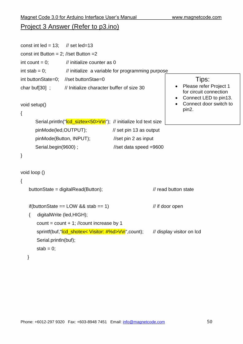
Project 3 Answer (Refer to p3.ino)
const int led = 13; // set led=13
const int Button = 2; //set Button =2
int count = 0; // initialize counter as 0
int stab = 0; // initialize a variable for programming purpose
int buttonState=0; //set buttonStae=0
char buf[30] ; // Initialize character buffer of size 30
void setup()
{
Serial.println("lcd_siztex<50>\r\n"); // initialize lcd text size
pinMode(led,OUTPUT); // set pin 13 as output
pinMode(Button, INPUT); //set pin 2 as input
Serial.begin(9600) ; //set data speed =9600
}
void loop ()
{
buttonState = digitalRead(Button); // read button state
if(buttonState == LOW && stab == 1) // if door open
{ digitalWrite (led,HIGH);
count = count + 1; //count increase by 1
sprintf(buf,"lcd_shotex< Visitor: #%d>\r\n",count); // display visitor on lcd
Serial.println(buf);
stab = 0;
}
Tips: Please refer Project 1
for circuit connection
Connect LED to pin13.
Connect door switch to pin2.
Magnet Code 3.0 for Arduino Interface User‟s Manual www.magnetcode.com
Phone: +6012-297 9320 Fax: +603-8948 7451 Email: [email protected] 51
else if (buttonState == HIGH && stab == 0) // if door close
{
digitalWrite (led,LOW); //led off
stab=1;
}
delay (250);
}
Magnet Code 3.0 for Arduino Interface User‟s Manual www.magnetcode.com
Phone: +6012-297 9320 Fax: +603-8948 7451 Email: [email protected] 52
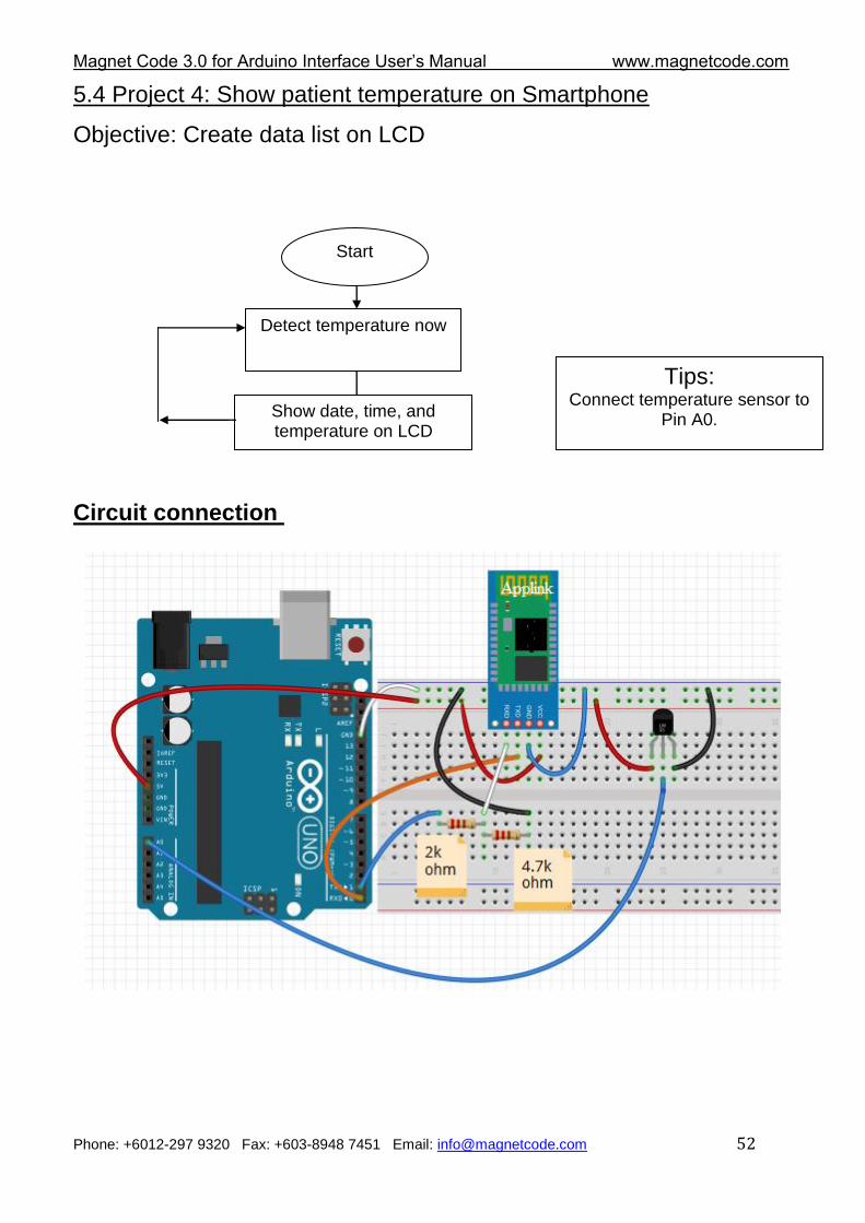
5.4 Project 4: Show patient temperature on Smartphone
Objective: Create data list on LCD
Circuit connection
Start
Detect temperature now
Show date, time, and temperature on LCD
Tips: Connect temperature sensor to
Pin A0.
Magnet Code 3.0 for Arduino Interface User‟s Manual www.magnetcode.com
Phone: +6012-297 9320 Fax: +603-8948 7451 Email: [email protected] 53
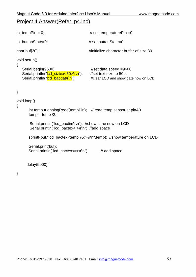
Project 4 Answer(Refer p4.ino) int tempPin = 0; // set temperaturePin =0 int buttonState=0; // set buttonState=0 char buf[30]; //initialize character buffer of size 30 void setup() { Serial.begin(9600); //set data speed =9600 Serial.println("lcd_siztex<50>\r\n"); //set text size to 50pt Serial.println("lcd_bacdat\r\n"); //clear LCD and show date now on LCD } void loop() { int temp = analogRead(tempPin); // read temp sensor at pinA0 temp = temp /2; Serial.println("lcd_bactim\r\n"); //show time now on LCD Serial.println("lcd_bactex< >\r\n"); //add space
sprintf(buf,"lcd_bactex<temp:%d>\r\n",temp); //show temperature on LCD Serial.print(buf); Serial.println("lcd_bactex<#>\r\n"); // add space delay(5000); }
Magnet Code 3.0 for Arduino Interface User‟s Manual www.magnetcode.com
Phone: +6012-297 9320 Fax: +603-8948 7451 Email: [email protected] 54
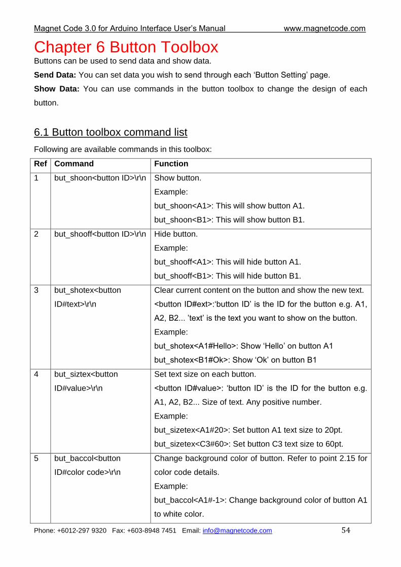
Chapter 6 Button Toolbox Buttons can be used to send data and show data.
Send Data: You can set data you wish to send through each „Button Setting‟ page.
Show Data: You can use commands in the button toolbox to change the design of each
button.
6.1 Button toolbox command list
Following are available commands in this toolbox:
Ref Command Function
1 but_shoon<button ID>\r\n Show button.
Example:
but_shoon<A1>: This will show button A1.
but_shoon<B1>: This will show button B1.
2 but_shooff<button ID>\r\n Hide button.
Example:
but_shooff<A1>: This will hide button A1.
but_shooff<B1>: This will hide button B1.
3 but_shotex<button
ID#text>\r\n
Clear current content on the button and show the new text.
<button ID#ext>:„button ID‟ is the ID for the button e.g. A1,
A2, B2... ‟text‟ is the text you want to show on the button.
Example:
but_shotex<A1#Hello>: Show „Hello‟ on button A1
but_shotex<B1#Ok>: Show „Ok‟ on button B1
4 but_siztex<button
ID#value>\r\n
Set text size on each button.
<button ID#value>: „button ID‟ is the ID for the button e.g.
A1, A2, B2... Size of text. Any positive number.
Example:
but_sizetex<A1#20>: Set button A1 text size to 20pt.
but_sizetex<C3#60>: Set button C3 text size to 60pt.
5 but_baccol<button
ID#color code>\r\n
Change background color of button. Refer to point 2.15 for
color code details.
Example:
but_baccol<A1#-1>: Change background color of button A1
to white color.
Magnet Code 3.0 for Arduino Interface User‟s Manual www.magnetcode.com
Phone: +6012-297 9320 Fax: +603-8948 7451 Email: [email protected] 55
6 but_frocol<button
ID#color code>\r\n
Change text color of button. Refer to point 2.15 for color
code details.
Example:
but_frocol<B2#-1>: Change text color of button B2 to white
color.
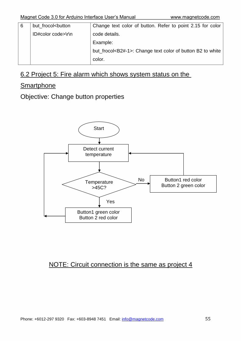
6.2 Project 5: Fire alarm which shows system status on the
Smartphone
Objective: Change button properties
NOTE: Circuit connection is the same as project 4
Start
Detect current temperature
Temperature >45C?
No
Yes
Button1 red color Button 2 green color
Button1 green color Button 2 red color
Magnet Code 3.0 for Arduino Interface User‟s Manual www.magnetcode.com
Phone: +6012-297 9320 Fax: +603-8948 7451 Email: [email protected] 56
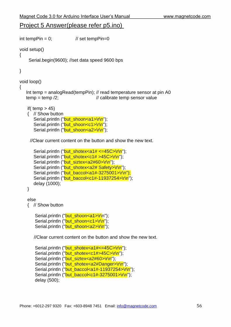
Project 5 Answer(please refer p5.ino) int tempPin = 0; // set tempPin=0 void setup() { Serial.begin(9600); //set data speed 9600 bps } void loop() { Int temp = analogRead(tempPin); // read temperature sensor at pin A0 temp = temp /2; // calibrate temp sensor value if( temp > 45) { // Show button
Serial.println ("but_shoon<a1>\r\n"); Serial.println ("but_shoon<c1>\r\n"); Serial.println ("but_shoon<a2>\r\n");
//Clear current content on the button and show the new text.
Serial.println ("but_shotex<a1# <=45C>\r\n"); Serial.println ("but_shotex<c1# >45C>\r\n"); Serial.println ("but_siztex<a2#60>\r\n"); Serial.println ("but_shotex<a2# Safety>\r\n"); Serial.println ("but_baccol<a1#-3275001>\r\n"); Serial.println ("but_baccol<c1#-11937254>\r\n"); delay (1000);
} else { // Show button Serial.println ("but_shoon<a1>\r\n");
Serial.println ("but_shoon<c1>\r\n"); Serial.println ("but_shoon<a2>\r\n");
//Clear current content on the button and show the new text.
Serial.println ("but_shotex<a1#<=45C>\r\n"); Serial.println ("but_shotex<c1#>45C>\r\n"); Serial.println ("but_siztex<a2#60>\r\n"); Serial.println ("but_shotex<a2#Danger>\r\n"); Serial.println ("but_baccol<a1#-11937254>\r\n"); Serial.println ("but_baccol<c1#-3275001>\r\n"); delay (500);
Magnet Code 3.0 for Arduino Interface User‟s Manual www.magnetcode.com
Phone: +6012-297 9320 Fax: +603-8948 7451 Email: [email protected] 57
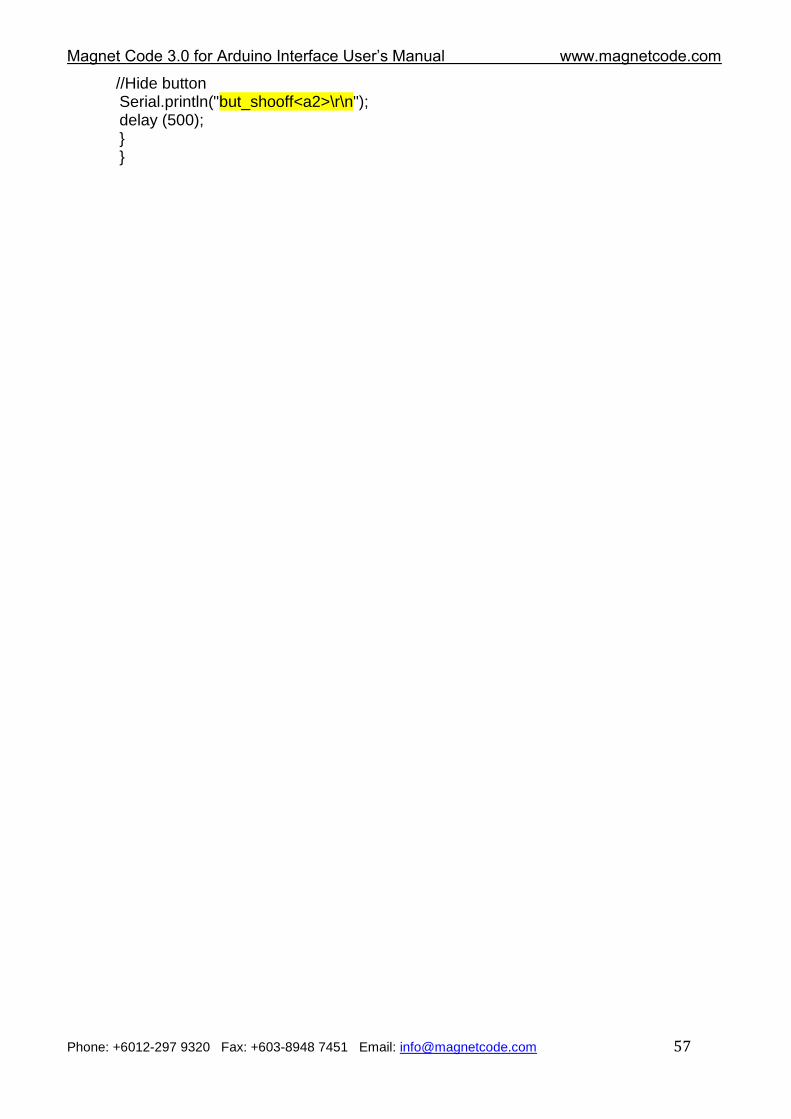
//Hide button Serial.println("but_shooff<a2>\r\n"); delay (500); } }
Magnet Code 3.0 for Arduino Interface User‟s Manual www.magnetcode.com
Phone: +6012-297 9320 Fax: +603-8948 7451 Email: [email protected] 58
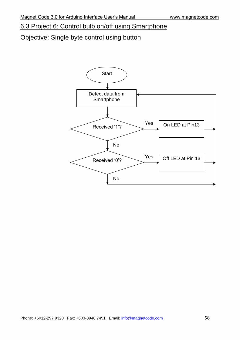
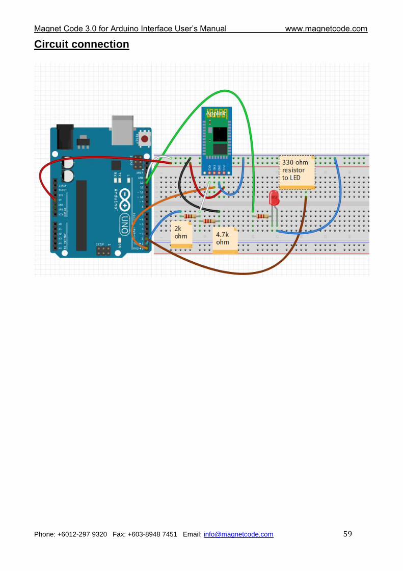
6.3 Project 6: Control bulb on/off using Smartphone
Objective: Single byte control using button
Start
Detect data from Smartphone
Received „1‟? On LED at Pin13 Yes
No
Received „0‟? Off LED at Pin 13 Yes
No
Magnet Code 3.0 for Arduino Interface User‟s Manual www.magnetcode.com
Phone: +6012-297 9320 Fax: +603-8948 7451 Email: [email protected] 59
Circuit connection
Magnet Code 3.0 for Arduino Interface User‟s Manual www.magnetcode.com
Phone: +6012-297 9320 Fax: +603-8948 7451 Email: [email protected] 60
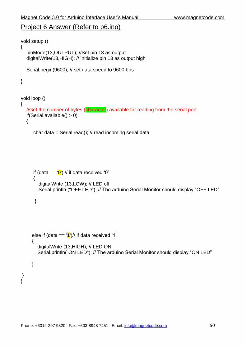
Project 6 Answer (Refer to p6.ino) void setup () { pinMode(13,OUTPUT); //Set pin 13 as output digitalWrite(13,HIGH); // initialize pin 13 as output high Serial.begin(9600); // set data speed to 9600 bps } void loop () { //Get the number of bytes (character) available for reading from the serial port if(Serial.available() > 0) { char data = Serial.read(); // read incoming serial data if (data == '0') // if data received „0‟ { digitalWrite (13,LOW); // LED off Serial.println ("OFF LED"); // The arduino Serial Monitor should display “OFF LED” } else if (data == '1')// if data received „1‟ { digitalWrite (13,HIGH); // LED ON Serial.println("ON LED"); // The arduino Serial Monitor should display “ON LED” } } }
Magnet Code 3.0 for Arduino Interface User‟s Manual www.magnetcode.com
Phone: +6012-297 9320 Fax: +603-8948 7451 Email: [email protected] 61
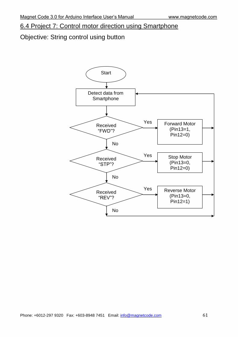
6.4 Project 7: Control motor direction using Smartphone
Objective: String control using button
Start
Detect data from Smartphone
Received “FWD”?
Forward Motor (Pin13=1, Pin12=0)
Yes
No
Received “STP”?
Stop Motor (Pin13=0, Pin12=0)
)
Yes
No
Received “REV”?
Reverse Motor (Pin13=0, Pin12=1)
Yes
No
Magnet Code 3.0 for Arduino Interface User‟s Manual www.magnetcode.com
Phone: +6012-297 9320 Fax: +603-8948 7451 Email: [email protected] 62
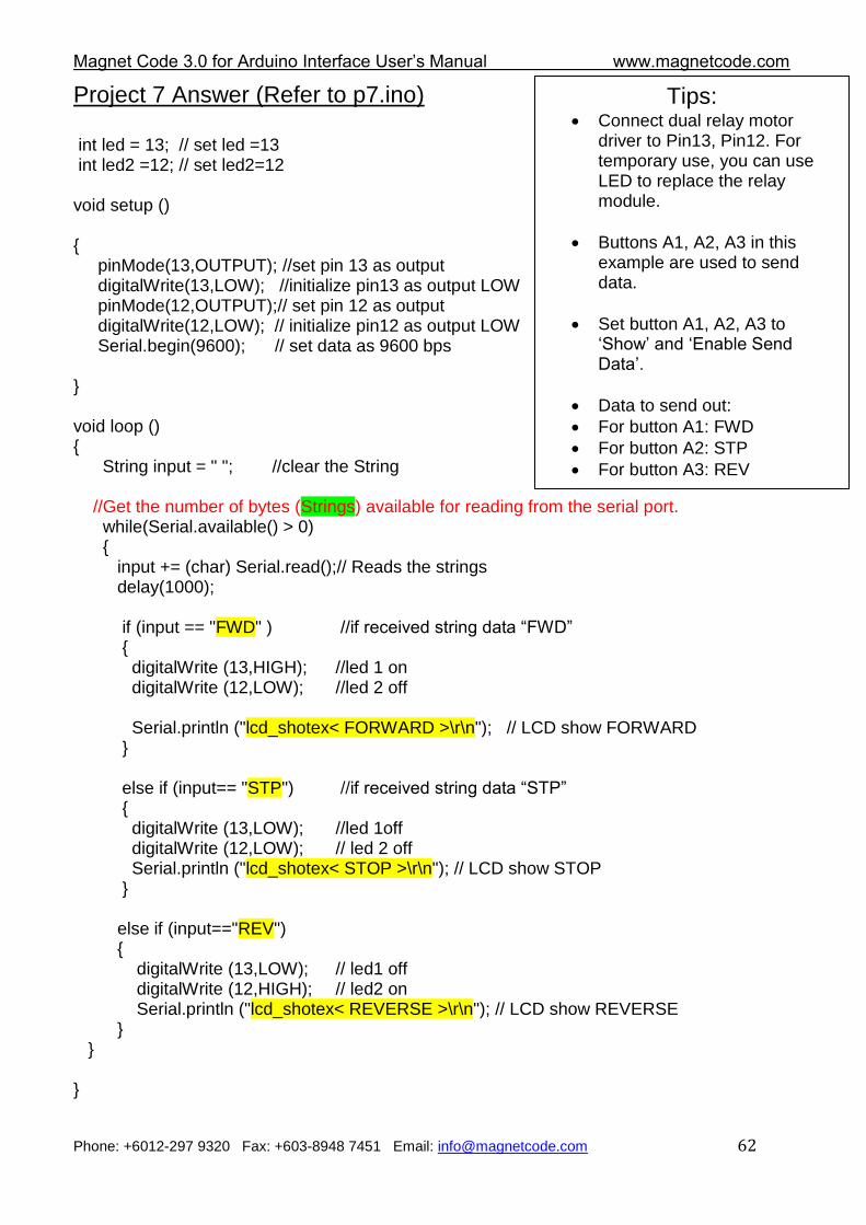
Project 7 Answer (Refer to p7.ino)
int led = 13; // set led =13 int led2 =12; // set led2=12 void setup () { pinMode(13,OUTPUT); //set pin 13 as output digitalWrite(13,LOW); //initialize pin13 as output LOW pinMode(12,OUTPUT);// set pin 12 as output digitalWrite(12,LOW); // initialize pin12 as output LOW Serial.begin(9600); // set data as 9600 bps } void loop () { String input = " "; //clear the String //Get the number of bytes (Strings) available for reading from the serial port. while(Serial.available() > 0) { input += (char) Serial.read();// Reads the strings delay(1000); if (input == "FWD" ) //if received string data “FWD” { digitalWrite (13,HIGH); //led 1 on digitalWrite (12,LOW); //led 2 off Serial.println ("lcd_shotex< FORWARD >\r\n"); // LCD show FORWARD } else if (input== "STP") //if received string data “STP” { digitalWrite (13,LOW); //led 1off digitalWrite (12,LOW); // led 2 off Serial.println ("lcd_shotex< STOP >\r\n"); // LCD show STOP } else if (input=="REV") { digitalWrite (13,LOW); // led1 off digitalWrite (12,HIGH); // led2 on Serial.println ("lcd_shotex< REVERSE >\r\n"); // LCD show REVERSE } } }
Tips: Connect dual relay motor
driver to Pin13, Pin12. For temporary use, you can use LED to replace the relay module.
Buttons A1, A2, A3 in this example are used to send data.
Set button A1, A2, A3 to „Show‟ and „Enable Send Data‟.
Data to send out:
For button A1: FWD
For button A2: STP
For button A3: REV
Magnet Code 3.0 for Arduino Interface User‟s Manual www.magnetcode.com
Phone: +6012-297 9320 Fax: +603-8948 7451 Email: [email protected] 63
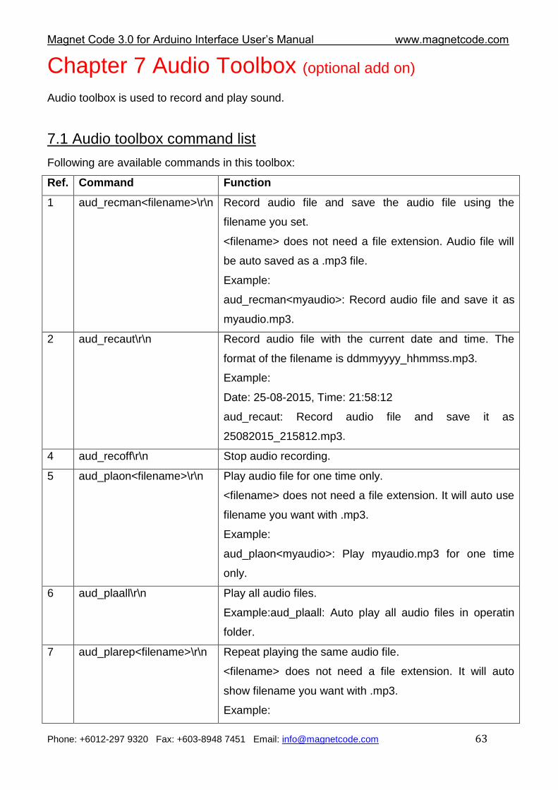
Chapter 7 Audio Toolbox (optional add on)
Audio toolbox is used to record and play sound.
7.1 Audio toolbox command list
Following are available commands in this toolbox:
Ref. Command Function
1 aud_recman<filename>\r\n Record audio file and save the audio file using the
filename you set.
<filename> does not need a file extension. Audio file will
be auto saved as a .mp3 file.
Example:
aud_recman<myaudio>: Record audio file and save it as
myaudio.mp3.
2 aud_recaut\r\n Record audio file with the current date and time. The
format of the filename is ddmmyyyy_hhmmss.mp3.
Example:
Date: 25-08-2015, Time: 21:58:12
aud_recaut: Record audio file and save it as
25082015_215812.mp3.
4 aud_recoff\r\n Stop audio recording.
5 aud_plaon<filename>\r\n Play audio file for one time only.
<filename> does not need a file extension. It will auto use
filename you want with .mp3.
Example:
aud_plaon<myaudio>: Play myaudio.mp3 for one time
only.
6 aud_plaall\r\n Play all audio files.
Example:aud_plaall: Auto play all audio files in operatin
folder.
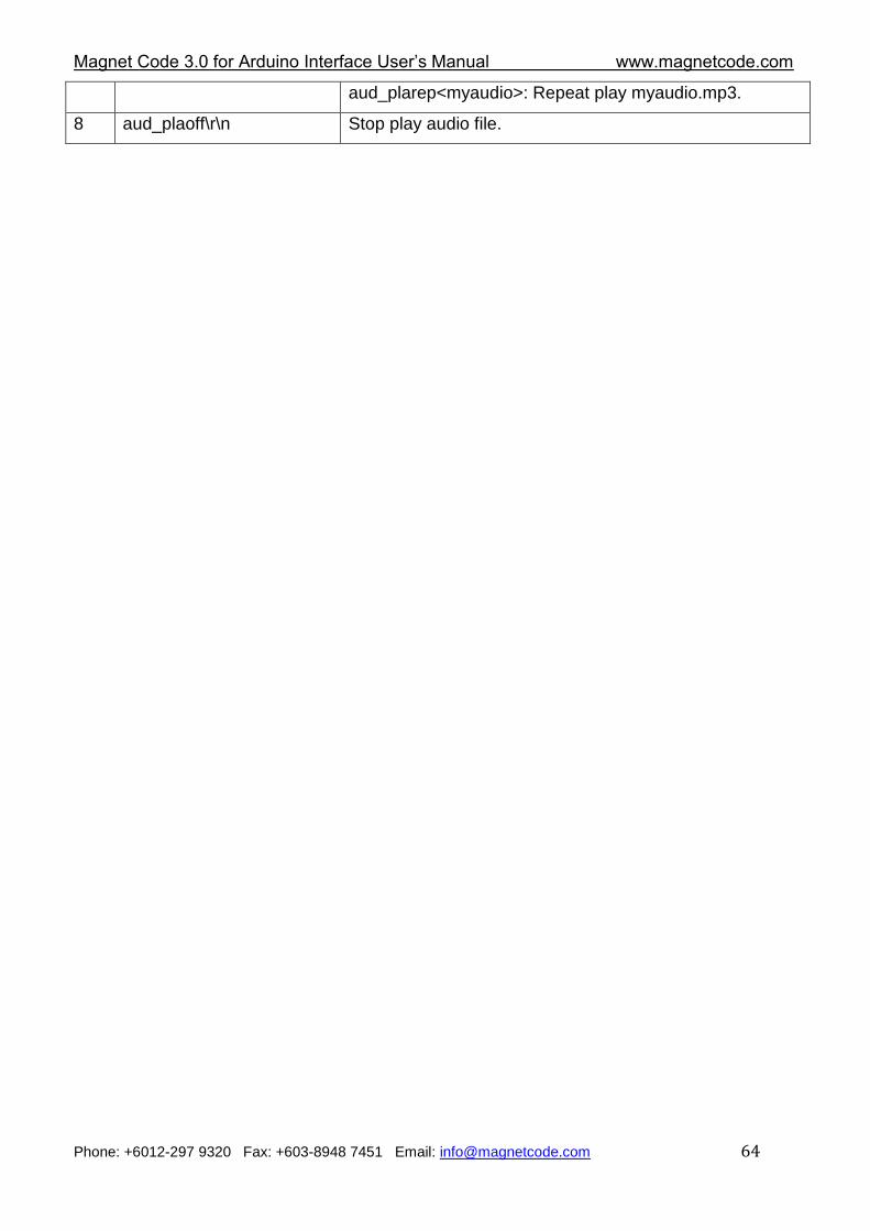
7 aud_plarep<filename>\r\n Repeat playing the same audio file.
<filename> does not need a file extension. It will auto
show filename you want with .mp3.
Example:
Magnet Code 3.0 for Arduino Interface User‟s Manual www.magnetcode.com
Phone: +6012-297 9320 Fax: +603-8948 7451 Email: [email protected] 64
aud_plarep<myaudio>: Repeat play myaudio.mp3.
8 aud_plaoff\r\n Stop play audio file.
Magnet Code 3.0 for Arduino Interface User‟s Manual www.magnetcode.com
Phone: +6012-297 9320 Fax: +603-8948 7451 Email: [email protected] 65
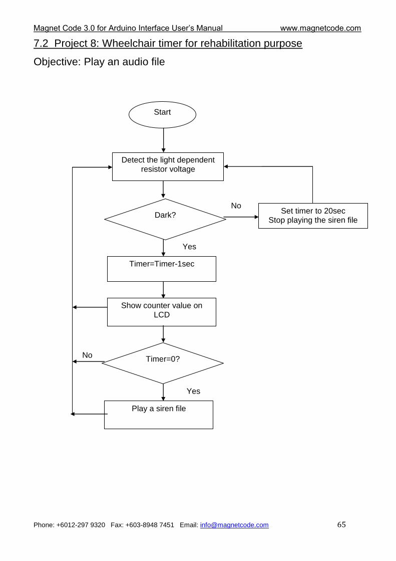
7.2 Project 8: Wheelchair timer for rehabilitation purpose
Objective: Play an audio file
Start
Detect the light dependent resistor voltage
Dark? No
Yes
Show counter value on LCD
Timer=Timer-1sec
Set timer to 20sec Stop playing the siren file
Timer=0?
Yes
No
Play a siren file
Magnet Code 3.0 for Arduino Interface User‟s Manual www.magnetcode.com
Phone: +6012-297 9320 Fax: +603-8948 7451 Email: [email protected] 66
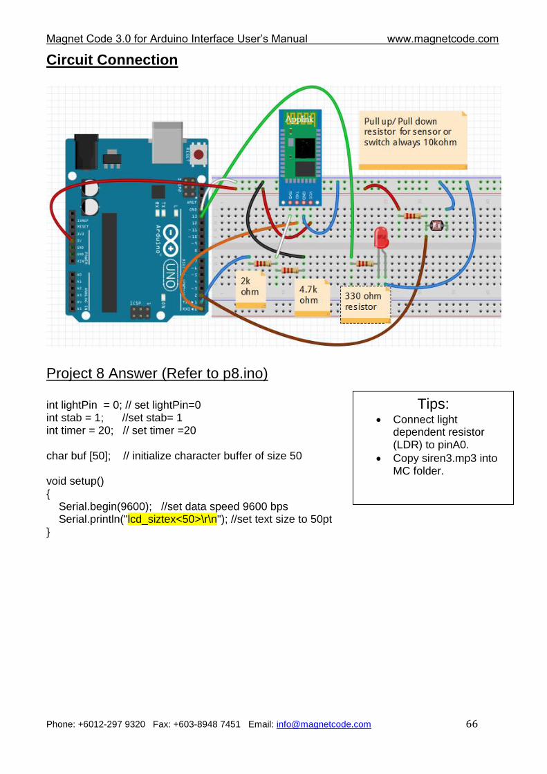
Circuit Connection
Project 8 Answer (Refer to p8.ino) int lightPin = 0; // set lightPin=0 int stab = 1; //set stab= 1 int timer = 20; // set timer =20 char buf [50]; // initialize character buffer of size 50 void setup() { Serial.begin(9600); //set data speed 9600 bps Serial.println("lcd_siztex<50>\r\n"); //set text size to 50pt }
Tips: Connect light
dependent resistor (LDR) to pinA0.
Copy siren3.mp3 into MC folder.
Magnet Code 3.0 for Arduino Interface User‟s Manual www.magnetcode.com
Phone: +6012-297 9320 Fax: +603-8948 7451 Email: [email protected] 67
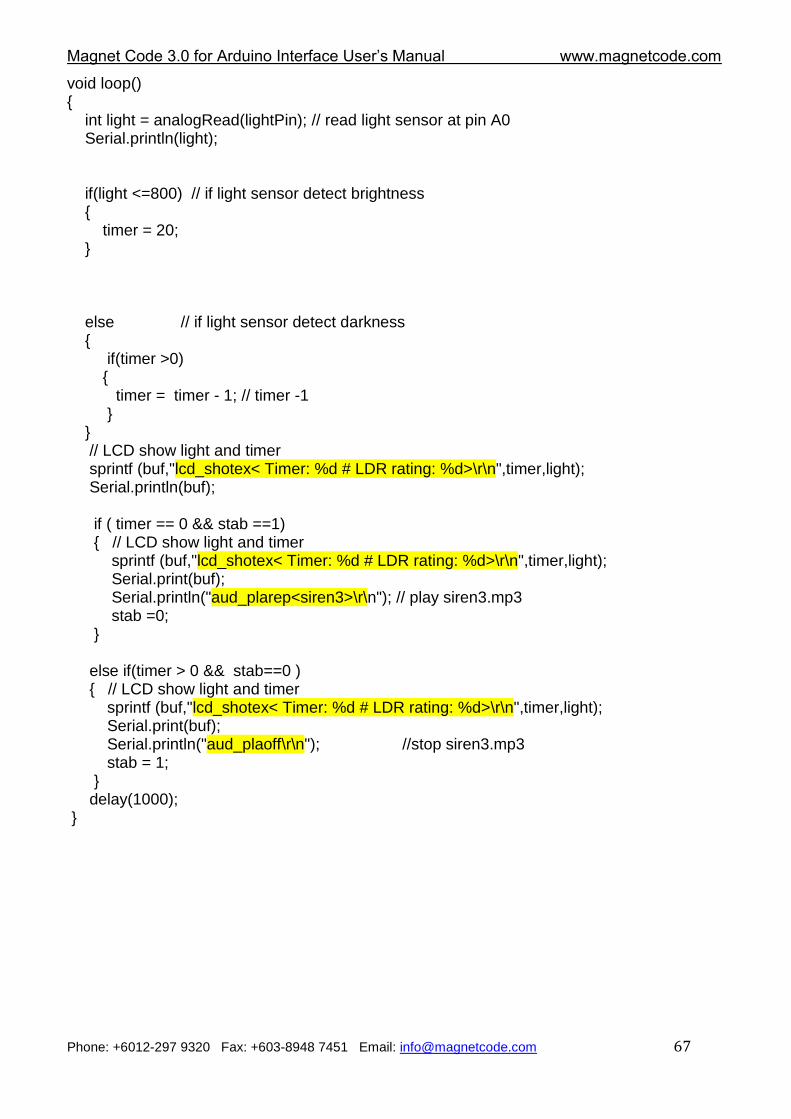
void loop() { int light = analogRead(lightPin); // read light sensor at pin A0 Serial.println(light); if(light <=800) // if light sensor detect brightness { timer = 20; } else // if light sensor detect darkness { if(timer >0) { timer = timer - 1; // timer -1 } } // LCD show light and timer sprintf (buf,"lcd_shotex< Timer: %d # LDR rating: %d>\r\n",timer,light); Serial.println(buf); if ( timer == 0 && stab ==1) { // LCD show light and timer sprintf (buf,"lcd_shotex< Timer: %d # LDR rating: %d>\r\n",timer,light); Serial.print(buf); Serial.println("aud_plarep<siren3>\r\n"); // play siren3.mp3 stab =0; } else if(timer > 0 && stab==0 ) { // LCD show light and timer sprintf (buf,"lcd_shotex< Timer: %d # LDR rating: %d>\r\n",timer,light); Serial.print(buf); Serial.println("aud_plaoff\r\n"); //stop siren3.mp3 stab = 1; } delay(1000); }
Magnet Code 3.0 for Arduino Interface User‟s Manual www.magnetcode.com
Phone: +6012-297 9320 Fax: +603-8948 7451 Email: [email protected] 68
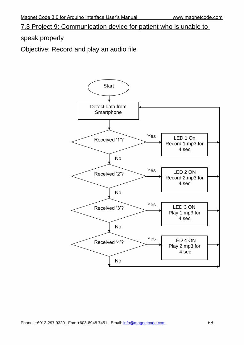
7.3 Project 9: Communication device for patient who is unable to
speak properly
Objective: Record and play an audio file
Start
Detect data from Smartphone
Received „1‟? LED 1 On Record 1.mp3 for
4 sec
Yes
No
Received „2‟? LED 2 ON Record 2.mp3 for
4 sec
Yes
No
Received „3‟? LED 3 ON Play 1.mp3 for
4 sec
Yes
No
Received „4‟? LED 4 ON Play 2.mp3 for
4 sec
Yes
No
Magnet Code 3.0 for Arduino Interface User‟s Manual www.magnetcode.com
Phone: +6012-297 9320 Fax: +603-8948 7451 Email: [email protected] 69
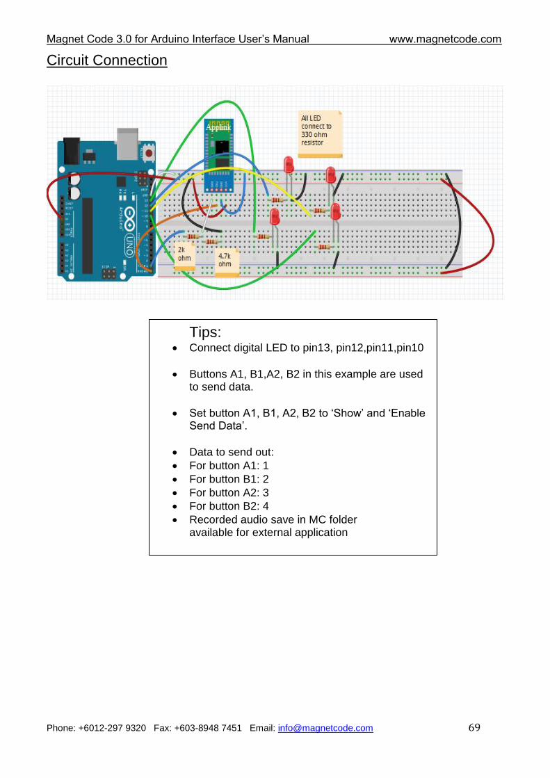
Circuit Connection
Tips: Connect digital LED to pin13, pin12,pin11,pin10
Buttons A1, B1,A2, B2 in this example are used to send data.
Set button A1, B1, A2, B2 to „Show‟ and „Enable Send Data‟.
Data to send out:
For button A1: 1
For button B1: 2
For button A2: 3
For button B2: 4
Recorded audio save in MC folder available for external application
Magnet Code 3.0 for Arduino Interface User‟s Manual www.magnetcode.com
Phone: +6012-297 9320 Fax: +603-8948 7451 Email: [email protected] 70
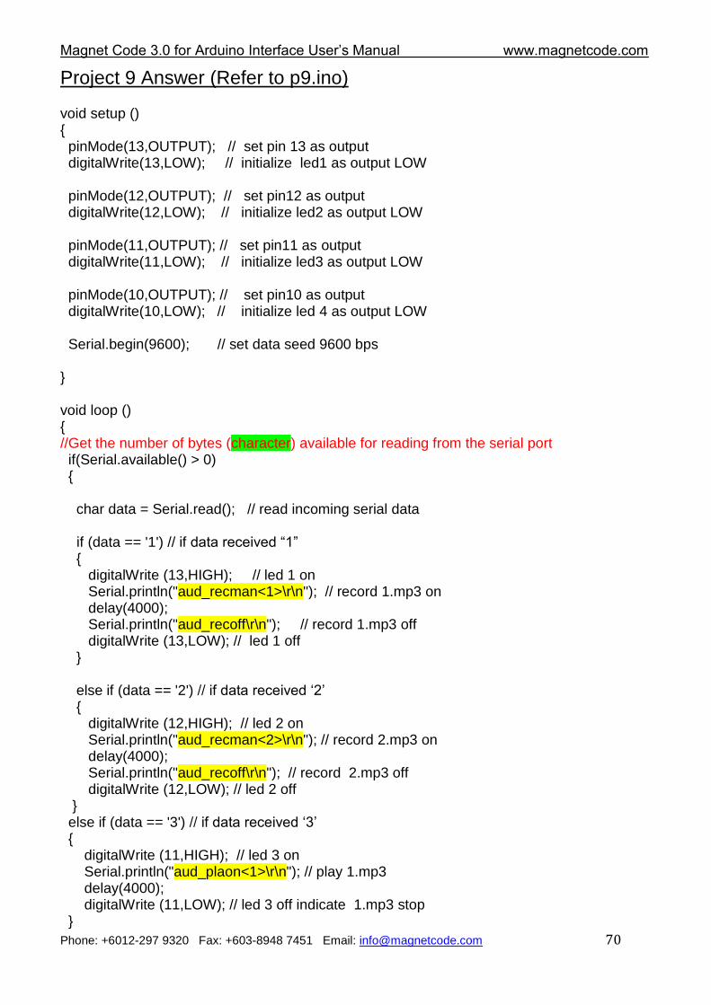
Project 9 Answer (Refer to p9.ino) void setup () { pinMode(13,OUTPUT); // set pin 13 as output digitalWrite(13,LOW); // initialize led1 as output LOW pinMode(12,OUTPUT); // set pin12 as output digitalWrite(12,LOW); // initialize led2 as output LOW pinMode(11,OUTPUT); // set pin11 as output digitalWrite(11,LOW); // initialize led3 as output LOW pinMode(10,OUTPUT); // set pin10 as output digitalWrite(10,LOW); // initialize led 4 as output LOW Serial.begin(9600); // set data seed 9600 bps } void loop () { //Get the number of bytes (character) available for reading from the serial port if(Serial.available() > 0) { char data = Serial.read(); // read incoming serial data
if (data == '1') // if data received “1” { digitalWrite (13,HIGH); // led 1 on Serial.println("aud_recman<1>\r\n"); // record 1.mp3 on delay(4000); Serial.println("aud_recoff\r\n"); // record 1.mp3 off digitalWrite (13,LOW); // led 1 off } else if (data == '2') // if data received „2‟ { digitalWrite (12,HIGH); // led 2 on Serial.println("aud_recman<2>\r\n"); // record 2.mp3 on delay(4000); Serial.println("aud_recoff\r\n"); // record 2.mp3 off digitalWrite (12,LOW); // led 2 off } else if (data == '3') // if data received „3‟ { digitalWrite (11,HIGH); // led 3 on Serial.println("aud_plaon<1>\r\n"); // play 1.mp3 delay(4000); digitalWrite (11,LOW); // led 3 off indicate 1.mp3 stop }
Magnet Code 3.0 for Arduino Interface User‟s Manual www.magnetcode.com
Phone: +6012-297 9320 Fax: +603-8948 7451 Email: [email protected] 71
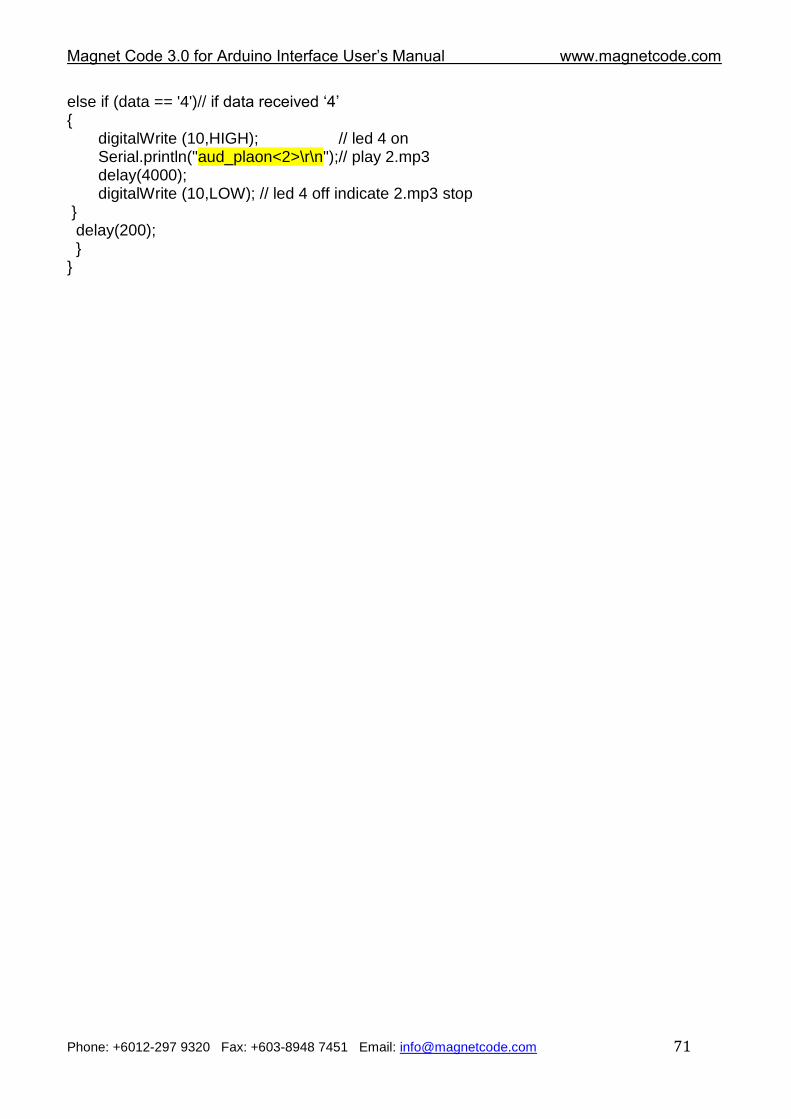
else if (data == '4')// if data received „4‟ { digitalWrite (10,HIGH); // led 4 on Serial.println("aud_plaon<2>\r\n");// play 2.mp3 delay(4000); digitalWrite (10,LOW); // led 4 off indicate 2.mp3 stop } delay(200); } }
Magnet Code 3.0 for Arduino Interface User‟s Manual www.magnetcode.com
Phone: +6012-297 9320 Fax: +603-8948 7451 Email: [email protected] 72
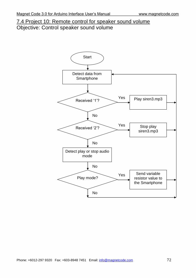
7.4 Project 10: Remote control for speaker sound volume
Objective: Control speaker sound volume
Start
Detect data from Smartphone
Received „1‟? Play siren3.mp3 Yes
No
Received „2‟? Stop play siren3.mp3
Yes
No
No
Play mode? Send variable
resistor value to the Smartphone
Yes
No
Detect play or stop audio mode
Magnet Code 3.0 for Arduino Interface User‟s Manual www.magnetcode.com
Phone: +6012-297 9320 Fax: +603-8948 7451 Email: [email protected] 73
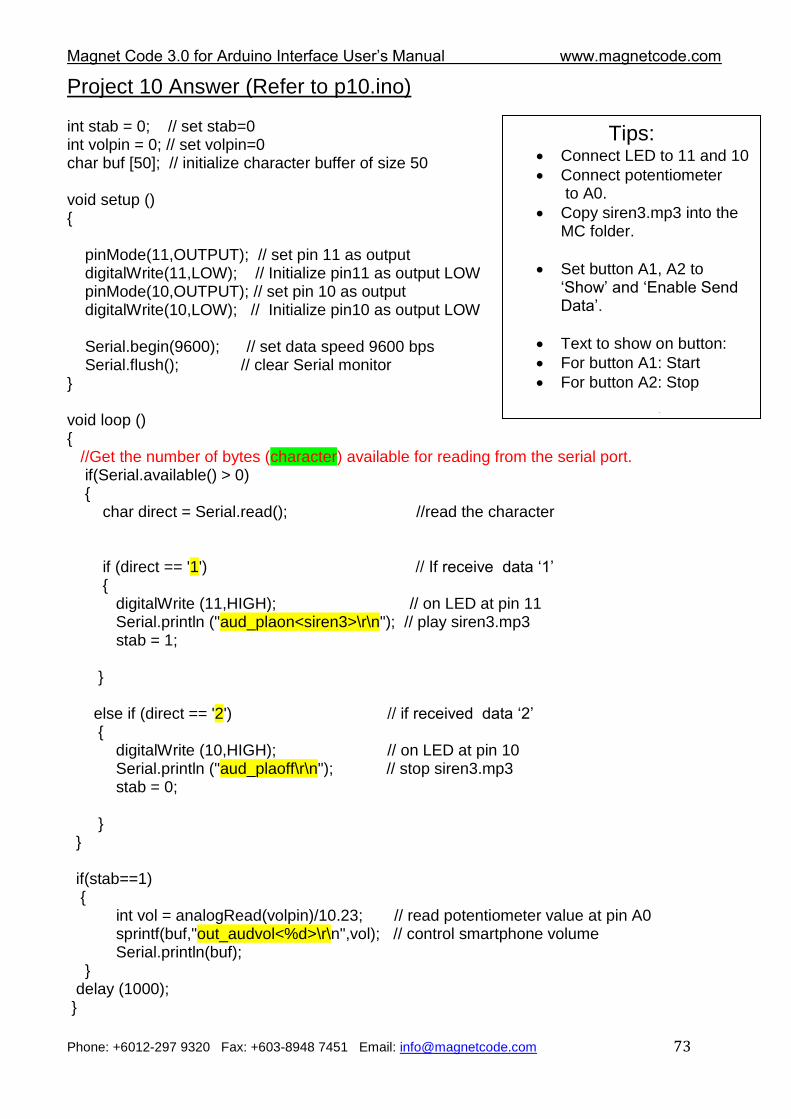
Project 10 Answer (Refer to p10.ino) int stab = 0; // set stab=0 int volpin = 0; // set volpin=0 char buf [50]; // initialize character buffer of size 50 void setup () { pinMode(11,OUTPUT); // set pin 11 as output digitalWrite(11,LOW); // Initialize pin11 as output LOW pinMode(10,OUTPUT); // set pin 10 as output digitalWrite(10,LOW); // Initialize pin10 as output LOW Serial.begin(9600); // set data speed 9600 bps Serial.flush(); // clear Serial monitor } void loop () { //Get the number of bytes (character) available for reading from the serial port. if(Serial.available() > 0) { char direct = Serial.read(); //read the character if (direct == '1') // If receive data „1‟ { digitalWrite (11,HIGH); // on LED at pin 11 Serial.println ("aud_plaon<siren3>\r\n"); // play siren3.mp3 stab = 1; } else if (direct == '2') // if received data „2‟ { digitalWrite (10,HIGH); // on LED at pin 10 Serial.println ("aud_plaoff\r\n"); // stop siren3.mp3 stab = 0; } } if(stab==1) { int vol = analogRead(volpin)/10.23; // read potentiometer value at pin A0 sprintf(buf,"out_audvol<%d>\r\n",vol); // control smartphone volume Serial.println(buf); } delay (1000); }
Tips: Connect LED to 11 and 10
Connect potentiometer to A0.
Copy siren3.mp3 into the MC folder.
Set button A1, A2 to „Show‟ and „Enable Send Data‟.
Text to show on button:
For button A1: Start
For button A2: Stop
Data to send out: For button A1: 1 For button A2: 2
Magnet Code 3.0 for Arduino Interface User‟s Manual www.magnetcode.com
Phone: +6012-297 9320 Fax: +603-8948 7451 Email: [email protected] 74
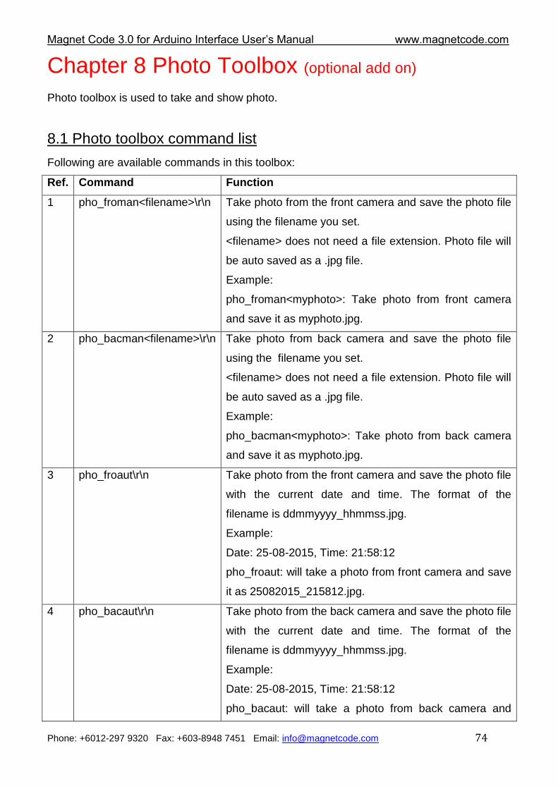
Chapter 8 Photo Toolbox (optional add on)
Photo toolbox is used to take and show photo.
8.1 Photo toolbox command list
Following are available commands in this toolbox:
Ref. Command Function
1 pho_froman<filename>\r\n Take photo from the front camera and save the photo file
using the filename you set.
<filename> does not need a file extension. Photo file will
be auto saved as a .jpg file.
Example:
pho_froman<myphoto>: Take photo from front camera
and save it as myphoto.jpg.
2 pho_bacman<filename>\r\n Take photo from back camera and save the photo file
using the filename you set.
<filename> does not need a file extension. Photo file will
be auto saved as a .jpg file.
Example:
pho_bacman<myphoto>: Take photo from back camera
and save it as myphoto.jpg.
3 pho_froaut\r\n Take photo from the front camera and save the photo file
with the current date and time. The format of the
filename is ddmmyyyy_hhmmss.jpg.
Example:
Date: 25-08-2015, Time: 21:58:12
pho_froaut: will take a photo from front camera and save
it as 25082015_215812.jpg.
4 pho_bacaut\r\n Take photo from the back camera and save the photo file
with the current date and time. The format of the
filename is ddmmyyyy_hhmmss.jpg.
Example:
Date: 25-08-2015, Time: 21:58:12
pho_bacaut: will take a photo from back camera and
Magnet Code 3.0 for Arduino Interface User‟s Manual www.magnetcode.com
Phone: +6012-297 9320 Fax: +603-8948 7451 Email: [email protected] 75
save it as 25082015_215812.jpg.
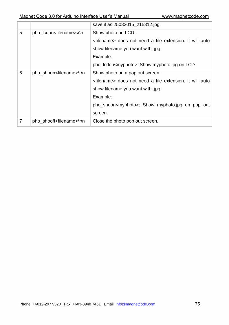
5 pho_lcdon<filename>\r\n Show photo on LCD.
<filename> does not need a file extension. It will auto
show filename you want with .jpg.
Example:
pho_lcdon<myphoto>: Show myphoto.jpg on LCD.
6 pho_shoon<filename>\r\n Show photo on a pop out screen.
<filename> does not need a file extension. It will auto
show filename you want with .jpg.
Example:
pho_shoon<myphoto>: Show myphoto.jpg on pop out
screen.
7 pho_shooff<filename>\r\n Close the photo pop out screen.
Magnet Code 3.0 for Arduino Interface User‟s Manual www.magnetcode.com
Phone: +6012-297 9320 Fax: +603-8948 7451 Email: [email protected] 76
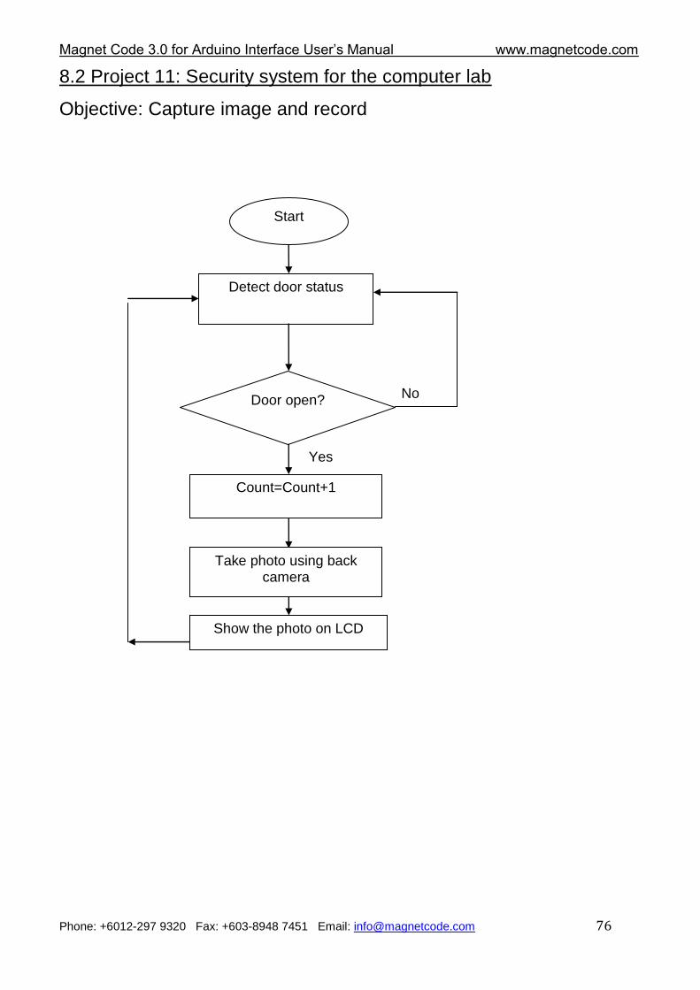
8.2 Project 11: Security system for the computer lab
Objective: Capture image and record
Start
Detect door status
Door open? No
Yes
Take photo using back camera
Count=Count+1
Show the photo on LCD
Magnet Code 3.0 for Arduino Interface User‟s Manual www.magnetcode.com
Phone: +6012-297 9320 Fax: +603-8948 7451 Email: [email protected] 77
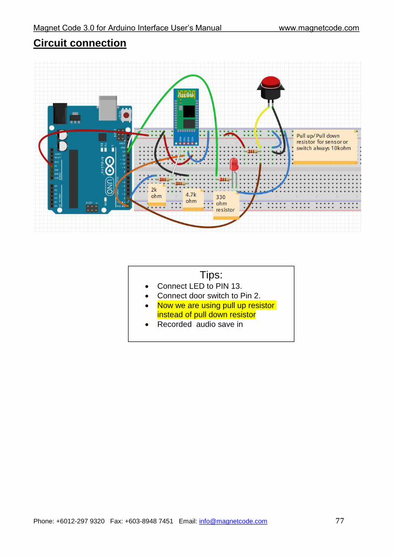
Circuit connection
Tips: Connect LED to PIN 13.
Connect door switch to Pin 2.
Now we are using pull up resistor instead of pull down resistor
Recorded audio save in
Magnet Code 3.0 for Arduino Interface User‟s Manual www.magnetcode.com
Phone: +6012-297 9320 Fax: +603-8948 7451 Email: [email protected] 78
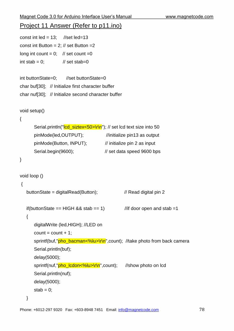
Project 11 Answer (Refer to p11.ino) const int led = 13; //set led=13
const int Button = 2; // set Button =2
long int count = 0; // set count =0
int stab = 0; // set stab=0
int buttonState=0; //set buttonState=0
char buf[30]; // Initialize first character buffer
char nuf[30]; // Initialize second character buffer
void setup()
{
Serial.println("lcd_siztex<50>\r\n"); // set lcd text size into 50
pinMode(led,OUTPUT); //initialize pin13 as output
pinMode(Button, INPUT); // initialize pin 2 as input
Serial.begin(9600); // set data speed 9600 bps
}
void loop ()
{
buttonState = digitalRead(Button); // Read digital pin 2
if(buttonState == HIGH && stab == 1) //if door open and stab =1
{
digitalWrite (led,HIGH); //LED on
count = count + 1;
sprintf(buf,"pho_bacman<%lu>\r\n",count); //take photo from back camera
Serial.println(buf);
delay(5000);
sprintf(nuf,"pho_lcdon<%lu>\r\n",count); //show photo on lcd
Serial.println(nuf);
delay(5000);
stab = 0;
}
Magnet Code 3.0 for Arduino Interface User‟s Manual www.magnetcode.com
Phone: +6012-297 9320 Fax: +603-8948 7451 Email: [email protected] 79
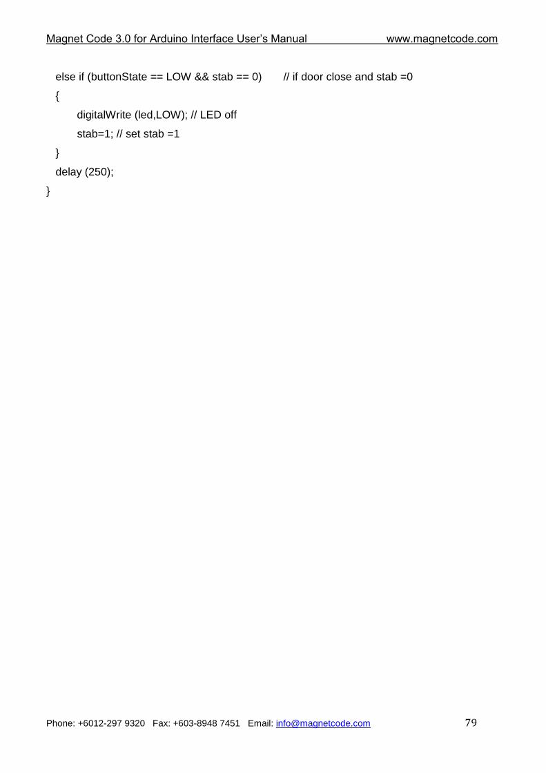
else if (buttonState == LOW && stab == 0) // if door close and stab =0
{
digitalWrite (led,LOW); // LED off
stab=1; // set stab =1
}
delay (250);
}
Magnet Code 3.0 for Arduino Interface User‟s Manual www.magnetcode.com
Phone: +6012-297 9320 Fax: +603-8948 7451 Email: [email protected] 80
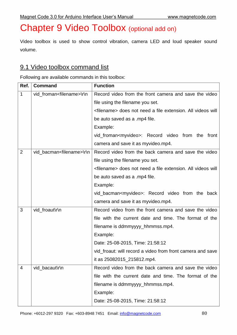
Chapter 9 Video Toolbox (optional add on)
Video toolbox is used to show control vibration, camera LED and loud speaker sound
volume.
9.1 Video toolbox command list
Following are available commands in this toolbox:
Ref. Command Function
1 vid_froman<filename>\r\n Record video from the front camera and save the video
file using the filename you set.
<filename> does not need a file extension. All videos will
be auto saved as a .mp4 file.
Example:
vid_froman<myvideo>: Record video from the front
camera and save it as myvideo.mp4.
2 vid_bacman<filename>\r\n Record video from the back camera and save the video
file using the filename you set.
<filename> does not need a file extension. All videos will
be auto saved as a .mp4 file.
Example:
vid_bacman<myvideo>: Record video from the back
camera and save it as myvideo.mp4.
3 vid_froaut\r\n Record video from the front camera and save the video
file with the current date and time. The format of the
filename is ddmmyyyy_hhmmss.mp4.
Example:
Date: 25-08-2015, Time: 21:58:12
vid_froaut: will record a video from front camera and save
it as 25082015_215812.mp4.
4 vid_bacaut\r\n Record video from the back camera and save the video
file with the current date and time. The format of the
filename is ddmmyyyy_hhmmss.mp4.
Example:
Date: 25-08-2015, Time: 21:58:12
Magnet Code 3.0 for Arduino Interface User‟s Manual www.magnetcode.com
Phone: +6012-297 9320 Fax: +603-8948 7451 Email: [email protected] 81
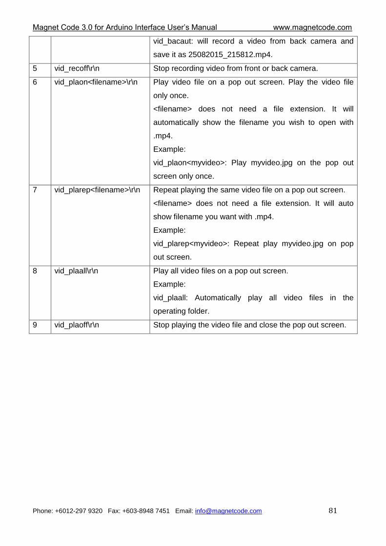
vid_bacaut: will record a video from back camera and
save it as 25082015_215812.mp4.
5 vid_recoff\r\n Stop recording video from front or back camera.
6 vid_plaon<filename>\r\n Play video file on a pop out screen. Play the video file
only once.
<filename> does not need a file extension. It will
automatically show the filename you wish to open with
.mp4.
Example:
vid_plaon<myvideo>: Play myvideo.jpg on the pop out
screen only once.
7 vid_plarep<filename>\r\n Repeat playing the same video file on a pop out screen.
<filename> does not need a file extension. It will auto
show filename you want with .mp4.
Example:
vid_plarep<myvideo>: Repeat play myvideo.jpg on pop
out screen.
8 vid_plaall\r\n Play all video files on a pop out screen.
Example:
vid_plaall: Automatically play all video files in the
operating folder.
9 vid_plaoff\r\n Stop playing the video file and close the pop out screen.
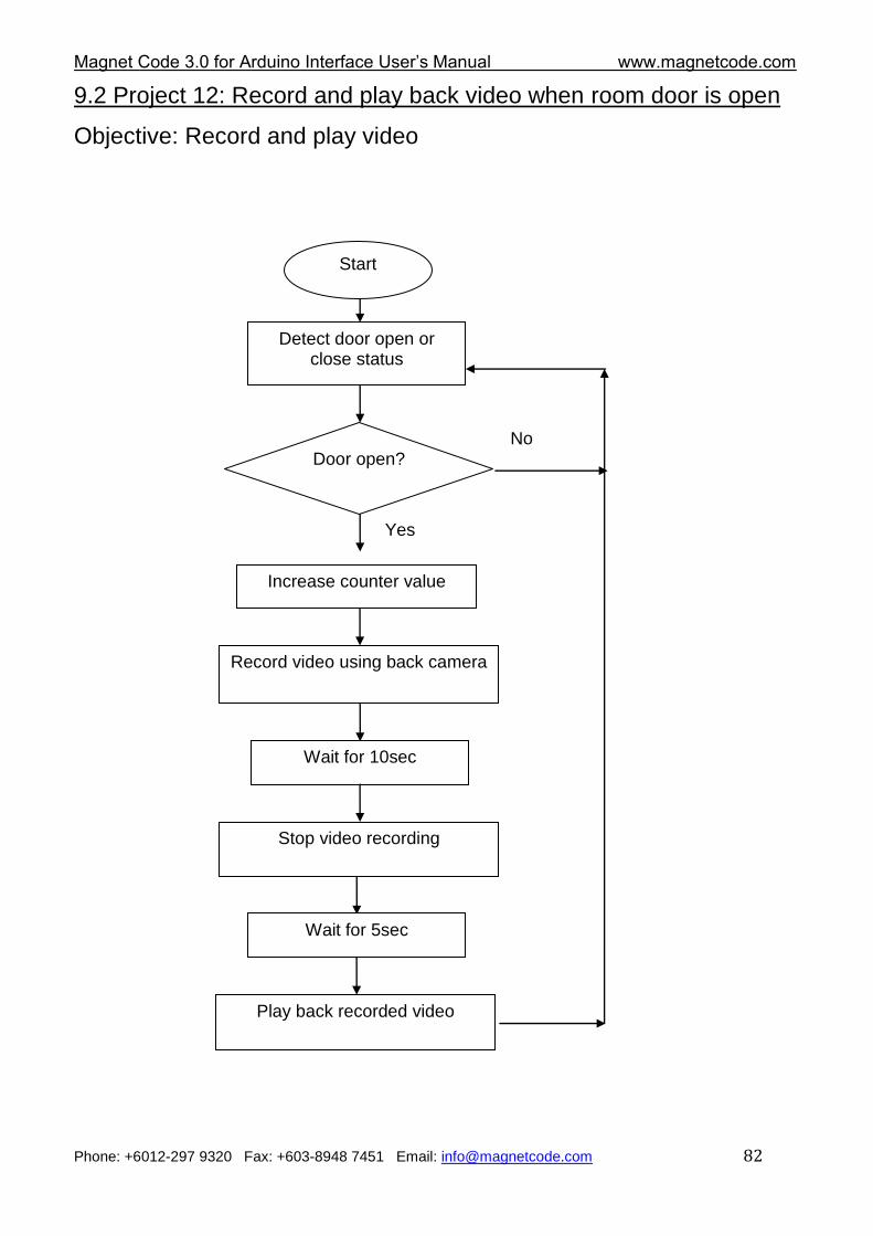
Magnet Code 3.0 for Arduino Interface User‟s Manual www.magnetcode.com
Phone: +6012-297 9320 Fax: +603-8948 7451 Email: [email protected] 82
9.2 Project 12: Record and play back video when room door is open
Objective: Record and play video
Start
Detect door open or close status
Door open? No
Yes
Record video using back camera
Wait for 10sec
Stop video recording
Increase counter value
Wait for 5sec
Play back recorded video
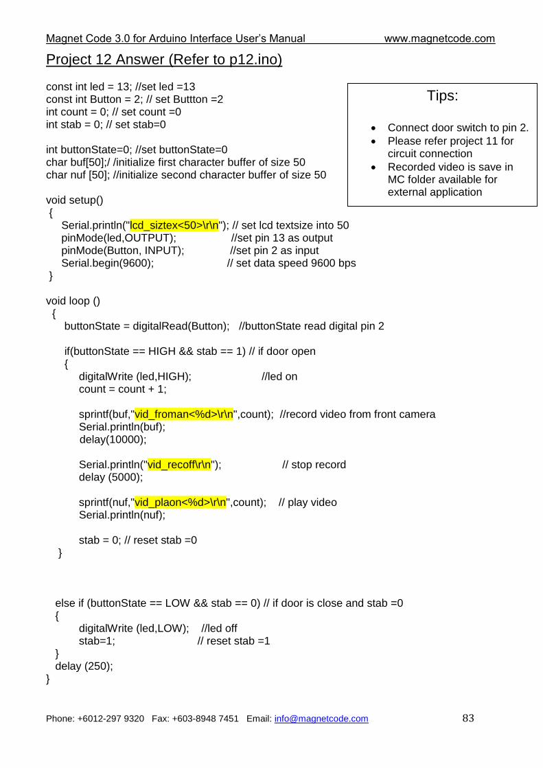
Magnet Code 3.0 for Arduino Interface User‟s Manual www.magnetcode.com
Phone: +6012-297 9320 Fax: +603-8948 7451 Email: [email protected] 83
Project 12 Answer (Refer to p12.ino) const int led = 13; //set led =13 const int Button = 2; // set Buttton =2 int count = 0; // set count =0 int stab = 0; // set stab=0 int buttonState=0; //set buttonState=0 char buf[50];/ /initialize first character buffer of size 50 char nuf [50]; //initialize second character buffer of size 50 void setup() { Serial.println("lcd_siztex<50>\r\n"); // set lcd textsize into 50 pinMode(led,OUTPUT); //set pin 13 as output pinMode(Button, INPUT); //set pin 2 as input Serial.begin(9600); // set data speed 9600 bps } void loop () { buttonState = digitalRead(Button); //buttonState read digital pin 2 if(buttonState == HIGH && stab == 1) // if door open { digitalWrite (led,HIGH); //led on count = count + 1; sprintf(buf,"vid_froman<%d>\r\n",count); //record video from front camera Serial.println(buf); delay(10000); Serial.println("vid_recoff\r\n"); // stop record delay (5000); sprintf(nuf,"vid_plaon<%d>\r\n",count); // play video Serial.println(nuf); stab = 0; // reset stab =0 } else if (buttonState == LOW && stab == 0) // if door is close and stab =0 { digitalWrite (led,LOW); //led off stab=1; // reset stab =1 } delay (250); }
Tips:
Connect door switch to pin 2.
Please refer project 11 for circuit connection
Recorded video is save in MC folder available for external application
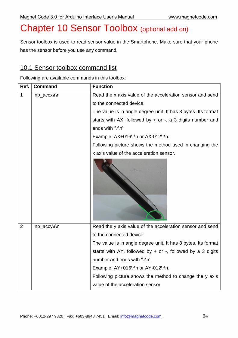
Magnet Code 3.0 for Arduino Interface User‟s Manual www.magnetcode.com
Phone: +6012-297 9320 Fax: +603-8948 7451 Email: [email protected] 84
Chapter 10 Sensor Toolbox (optional add on)
Sensor toolbox is used to read sensor value in the Smartphone. Make sure that your phone
has the sensor before you use any command.
10.1 Sensor toolbox command list
Following are available commands in this toolbox:
Ref. Command Function
1 inp_accx\r\n Read the x axis value of the acceleration sensor and send
to the connected device.
The value is in angle degree unit. It has 8 bytes. Its format
starts with AX, followed by + or -, a 3 digits number and
ends with „\r\n‟.
Example: AX+016\r\n or AX-012\r\n.
Following picture shows the method used in changing the
x axis value of the acceleration sensor.
2 inp_accy\r\n Read the y axis value of the acceleration sensor and send
to the connected device.
The value is in angle degree unit. It has 8 bytes. Its format
starts with AY, followed by + or -, followed by a 3 digits
number and ends with „\r\n‟.
Example: AY+016\r\n or AY-012\r\n.
Following picture shows the method to change the y axis
value of the acceleration sensor.
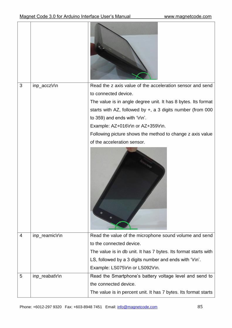
Magnet Code 3.0 for Arduino Interface User‟s Manual www.magnetcode.com
Phone: +6012-297 9320 Fax: +603-8948 7451 Email: [email protected] 85
3 inp_accz\r\n Read the z axis value of the acceleration sensor and send
to connected device.
The value is in angle degree unit. It has 8 bytes. Its format
starts with AZ, followed by +, a 3 digits number (from 000
to 359) and ends with „\r\n‟.
Example: AZ+016\r\n or AZ+359\r\n.
Following picture shows the method to change z axis value
of the acceleration sensor.
4 inp_reamic\r\n Read the value of the microphone sound volume and send
to the connected device.
The value is in db unit. It has 7 bytes. Its format starts with
LS, followed by a 3 digits number and ends with „\r\n‟.
Example: LS075\r\n or LS092\r\n.
5 inp_reabat\r\n Read the Smartphone‟s battery voltage level and send to
the connected device.
The value is in percent unit. It has 7 bytes. Its format starts
Magnet Code 3.0 for Arduino Interface User‟s Manual www.magnetcode.com
Phone: +6012-297 9320 Fax: +603-8948 7451 Email: [email protected] 86
with BL, followed by a 3 digits number (from 000 to 100)
and ends with „\r\n‟.
Example: BL023\r\n. or BL091\r\n.
6 inp_reacha\r\n Read the Smartphone charging status and send to the
connected device.
When the Smartphone is not charging, it will send
BC000\r\n to the connected device.
When the Smartphone is charging, it will send BC111\r\n
to the connected device.
7 inp_reatim\r\n Read the current Smartphone‟s time and send to the
connected device.
The value has 10 bytes. Its format starts with TN, followed
by hhmmss and ends with „\r\n‟..
Example:
If the current time is 03:18:07, it will send TN031807\r\n to
the connected device.
If the current time is 15:02:11, it will send TN150211\r\n to
the connected device.
8 inp_readat\r\n Read the current Smartphone‟s date and send to the
connected device.
The value has 12 bytes. Its format starts with FN, followed
by ddmmyyyy and ends with „\r\n‟.
Example:
If the current date is 25-08-2012, it will send
FN25082012\r\n to the connected device.
If the current date is 01-06-2013, it will send
FN01062013\r\n to the connected device.
9 inp_readay\r\n Read the current Smartphone‟s day and send to the
connected device.
The value has 5 bytes. Its format starts with DN, followed
by number 0 (Sunday) to 6 (Saturday) and ends with „\r\n‟.
Example:
If the current day is Sunday, it will send DN0\r\n to the
connected device.
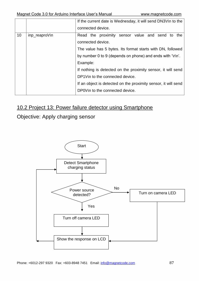
Magnet Code 3.0 for Arduino Interface User‟s Manual www.magnetcode.com
Phone: +6012-297 9320 Fax: +603-8948 7451 Email: [email protected] 87
If the current date is Wednesday, it will send DN3\r\n to the
connected device.
10 inp_reapro\r\n Read the proximity sensor value and send to the
connected device.
The value has 5 bytes. Its format starts with DN, followed
by number 0 to 9 (depends on phone) and ends with „\r\n‟.
Example:
If nothing is detected on the proximity sensor, it will send
DP1\r\n to the connected device.
If an object is detected on the proximity sensor, it will send
DP0\r\n to the connected device.
10.2 Project 13: Power failure detector using Smartphone
Objective: Apply charging sensor
Start
Detect Smartphone charging status
Power source detected?
No
Yes
Turn off camera LED
Show the response on LCD
Turn on camera LED
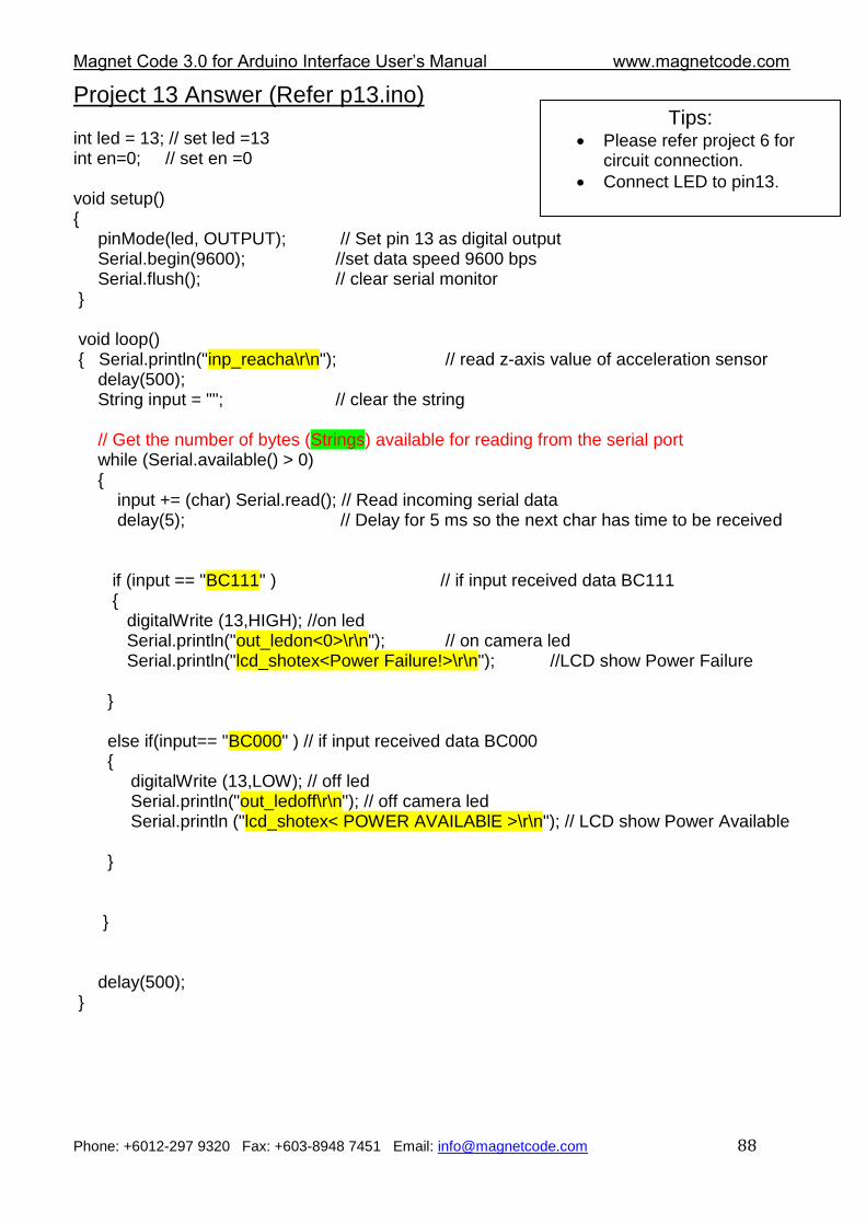
Magnet Code 3.0 for Arduino Interface User‟s Manual www.magnetcode.com
Phone: +6012-297 9320 Fax: +603-8948 7451 Email: [email protected] 88
Project 13 Answer (Refer p13.ino) int led = 13; // set led =13 int en=0; // set en =0 void setup() { pinMode(led, OUTPUT); // Set pin 13 as digital output Serial.begin(9600); //set data speed 9600 bps Serial.flush(); // clear serial monitor } void loop() { Serial.println("inp_reacha\r\n"); // read z-axis value of acceleration sensor delay(500); String input = ""; // clear the string // Get the number of bytes (Strings) available for reading from the serial port while (Serial.available() > 0) { input += (char) Serial.read(); // Read incoming serial data delay(5); // Delay for 5 ms so the next char has time to be received if (input == "BC111" ) // if input received data BC111 { digitalWrite (13,HIGH); //on led Serial.println("out_ledon<0>\r\n"); // on camera led Serial.println("lcd_shotex<Power Failure!>\r\n"); //LCD show Power Failure } else if(input== "BC000" ) // if input received data BC000 { digitalWrite (13,LOW); // off led Serial.println("out_ledoff\r\n"); // off camera led Serial.println ("lcd_shotex< POWER AVAILABlE >\r\n"); // LCD show Power Available } } delay(500); }
Tips: Please refer project 6 for
circuit connection.
Connect LED to pin13.
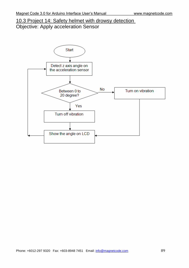
Magnet Code 3.0 for Arduino Interface User‟s Manual www.magnetcode.com
Phone: +6012-297 9320 Fax: +603-8948 7451 Email: [email protected] 89
10.3 Project 14: Safety helmet with drowsy detection Objective: Apply acceleration Sensor
Magnet Code 3.0 for Arduino Interface User‟s Manual www.magnetcode.com
Phone: +6012-297 9320 Fax: +603-8948 7451 Email: [email protected] 90
Project 14 Answer (Refer p14.ino)
String input; //set input as string data type
int en=0; // set en =0
//set data1--->data3 as integer data type
int data1;
int data2;
int data3;
int count=0; //set count =0
long int total; //set total into long integer data type
char buf[30]; // initialize character buffer of size 30
void setup()
{
Serial.begin(9600); //set data speed 9600 bps
pinMode(13,OUTPUT); // set pin 13 as digital output
}
void loop()
{
input =""; // clear the string
//Read the z axis value of the acceleration sensor and substitute to String input
Serial.println("inp_accz\r\n");
delay(500);
Tips: Please refer project 6 for
circuit connection
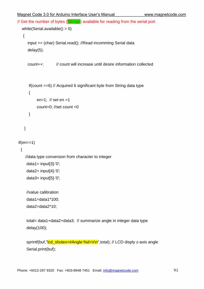
Magnet Code 3.0 for Arduino Interface User‟s Manual www.magnetcode.com
Phone: +6012-297 9320 Fax: +603-8948 7451 Email: [email protected] 91
// Get the number of bytes (Strings) available for reading from the serial port
while(Serial.available() > 0)
{
input += (char) Serial.read(); //Read incomming Serial data
delay(5);
count++; // count will increase until desire information collected
if(count ==6) // Acquired 6 significant byte from String data type
{
en=1; // set en =1
count=0; //set count =0
}
}
if(en==1)
{
//data type conversion from character to integer
data1= input[3]-'0';
data2= input[4]-'0';
data3= input[5]-'0';
//value calibration
data1=data1*100;
data2=data2*10;
total= data1+data2+data3; // summarize angle in integer data type
delay(100);
sprintf(buf,"lcd_shotex<#Angle:%d>\r\n",total); // LCD disply z-axis angle
Serial.print(buf);
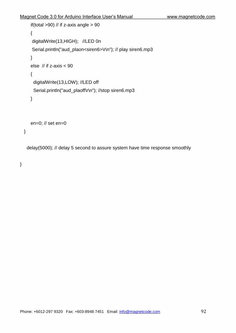
Magnet Code 3.0 for Arduino Interface User‟s Manual www.magnetcode.com
Phone: +6012-297 9320 Fax: +603-8948 7451 Email: [email protected] 92
if(total >90) // if z-axis angle > 90
{
digitalWrite(13,HIGH); //LED 0n
Serial.println("aud_plaon<siren6>\r\n"); // play siren6.mp3
}
else // if z-axis < 90
{
digitalWrite(13,LOW); //LED off
Serial.println("aud_plaoff\r\n"); //stop siren6.mp3
}
en=0; // set en=0
}
delay(5000); // delay 5 second to assure system have time response smoothly
}
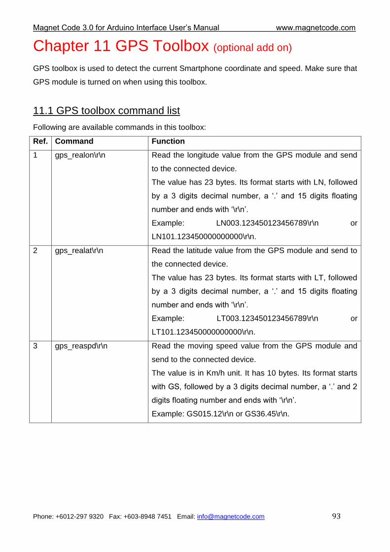
Magnet Code 3.0 for Arduino Interface User‟s Manual www.magnetcode.com
Phone: +6012-297 9320 Fax: +603-8948 7451 Email: [email protected] 93
Chapter 11 GPS Toolbox (optional add on)
GPS toolbox is used to detect the current Smartphone coordinate and speed. Make sure that
GPS module is turned on when using this toolbox.
11.1 GPS toolbox command list
Following are available commands in this toolbox:
Ref. Command Function
1 gps_realon\r\n Read the longitude value from the GPS module and send
to the connected device.
The value has 23 bytes. Its format starts with LN, followed
by a 3 digits decimal number, a „.‟ and 15 digits floating
number and ends with „\r\n‟.
Example: LN003.123450123456789\r\n or
LN101.123450000000000\r\n.
2 gps_realat\r\n Read the latitude value from the GPS module and send to
the connected device.
The value has 23 bytes. Its format starts with LT, followed
by a 3 digits decimal number, a „.‟ and 15 digits floating
number and ends with „\r\n‟.
Example: LT003.123450123456789\r\n or
LT101.123450000000000\r\n.
3 gps_reaspd\r\n Read the moving speed value from the GPS module and
send to the connected device.
The value is in Km/h unit. It has 10 bytes. Its format starts
with GS, followed by a 3 digits decimal number, a „.‟ and 2
digits floating number and ends with „\r\n‟.
Example: GS015.12\r\n or GS36.45\r\n.
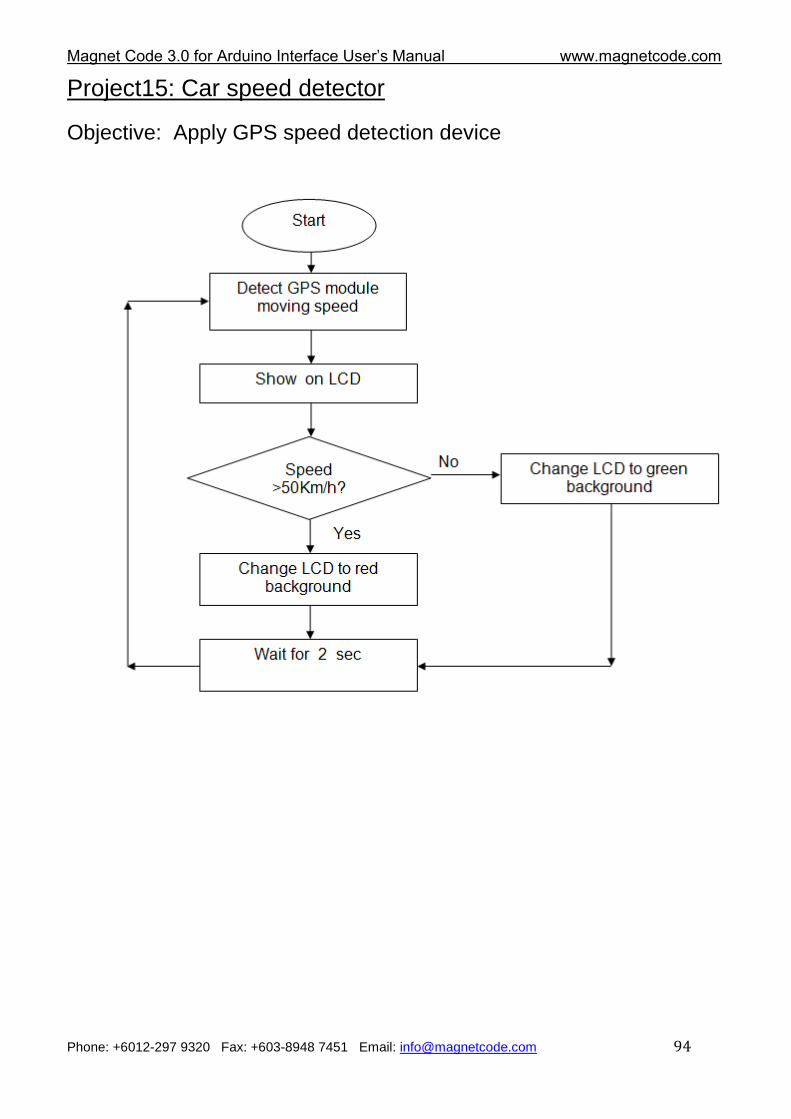
Magnet Code 3.0 for Arduino Interface User‟s Manual www.magnetcode.com
Phone: +6012-297 9320 Fax: +603-8948 7451 Email: [email protected] 94
Project15: Car speed detector
Objective: Apply GPS speed detection device
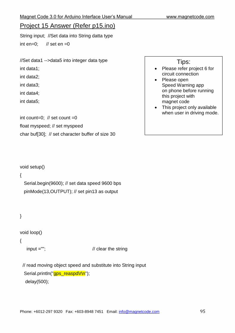
Magnet Code 3.0 for Arduino Interface User‟s Manual www.magnetcode.com
Phone: +6012-297 9320 Fax: +603-8948 7451 Email: [email protected] 95
Project 15 Answer (Refer p15.ino)
String input; //Set data into String datta type
int en=0; // set en =0
//Set data1 -->data5 into integer data type
int data1;
int data2;
int data3;
int data4;
int data5;
int count=0; // set count =0
float myspeed; // set myspeed
char buf[30]; // set character buffer of size 30
void setup()
{
Serial.begin(9600); // set data speed 9600 bps
pinMode(13,OUTPUT); // set pin13 as output
}
void loop()
{
input =""; // clear the string
// read moving object speed and substitute into String input
Serial.println("gps_reaspd\r\n");
delay(500);
Tips: Please refer project 6 for
circuit connection
Please open Speed Warning app on phone before running this project with magnet code
This project only available when user in driving mode.
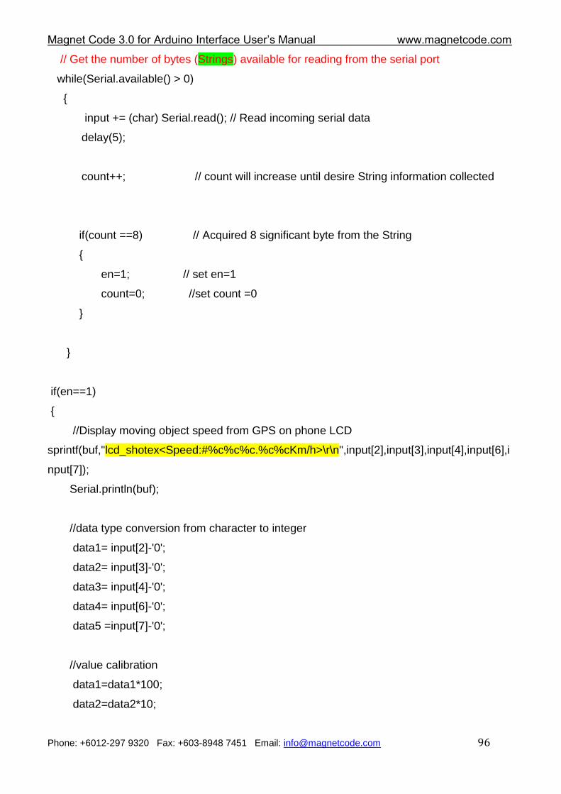
Magnet Code 3.0 for Arduino Interface User‟s Manual www.magnetcode.com
Phone: +6012-297 9320 Fax: +603-8948 7451 Email: [email protected] 96
// Get the number of bytes (Strings) available for reading from the serial port
while(Serial.available() > 0)
{
input += (char) Serial.read(); // Read incoming serial data
delay(5);
count++; // count will increase until desire String information collected
if(count ==8) // Acquired 8 significant byte from the String
{
en=1; // set en=1
count=0; //set count =0
}
}
if(en==1)
{
//Display moving object speed from GPS on phone LCD
sprintf(buf,"lcd_shotex<Speed:#%c%c%c.%c%cKm/h>\r\n",input[2],input[3],input[4],input[6],i
nput[7]);
Serial.println(buf);
//data type conversion from character to integer
data1= input[2]-'0';
data2= input[3]-'0';
data3= input[4]-'0';
data4= input[6]-'0';
data5 =input[7]-'0';
//value calibration
data1=data1*100;
data2=data2*10;
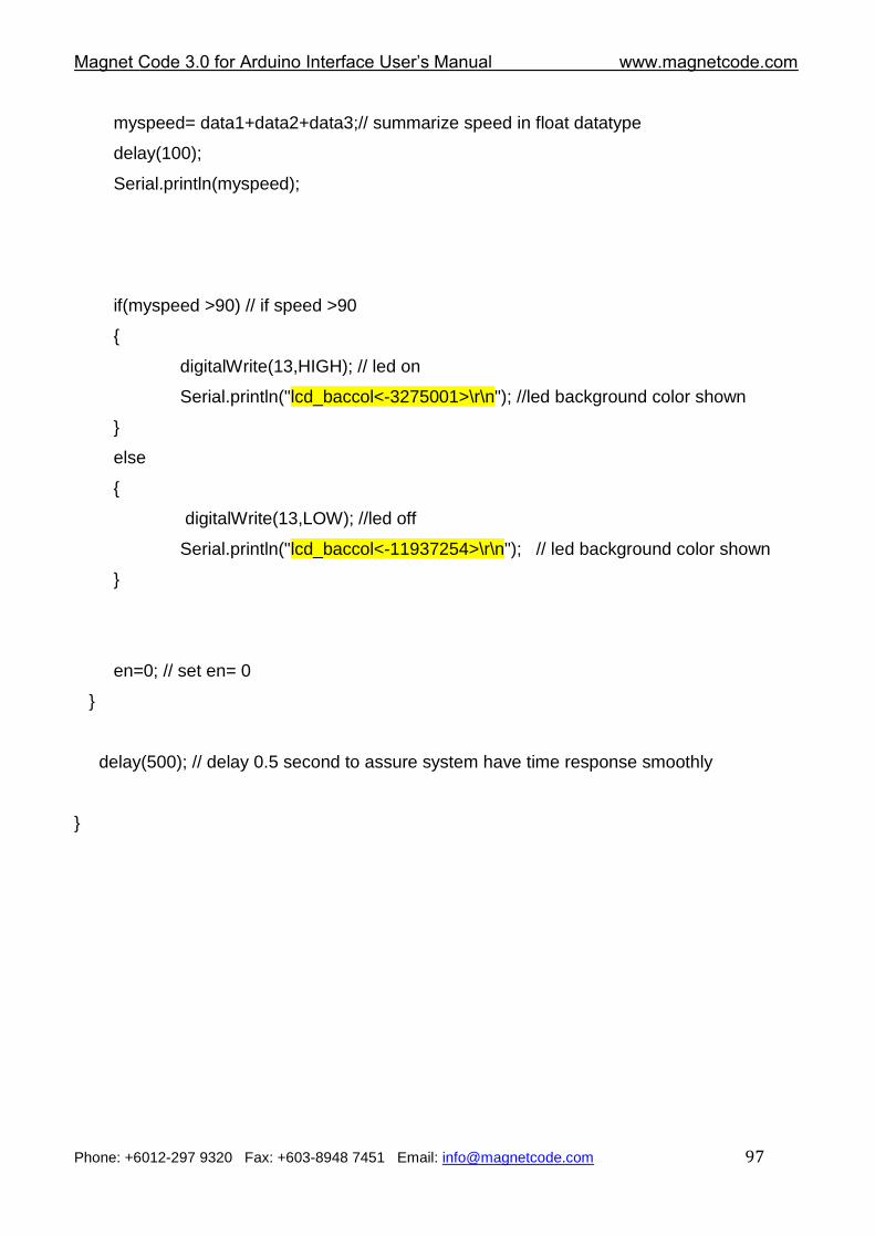
Magnet Code 3.0 for Arduino Interface User‟s Manual www.magnetcode.com
Phone: +6012-297 9320 Fax: +603-8948 7451 Email: [email protected] 97
myspeed= data1+data2+data3;// summarize speed in float datatype
delay(100);
Serial.println(myspeed);
if(myspeed >90) // if speed >90
{
digitalWrite(13,HIGH); // led on
Serial.println("lcd_baccol<-3275001>\r\n"); //led background color shown
}
else
{
digitalWrite(13,LOW); //led off
Serial.println("lcd_baccol<-11937254>\r\n"); // led background color shown
}
en=0; // set en= 0
}
delay(500); // delay 0.5 second to assure system have time response smoothly
}
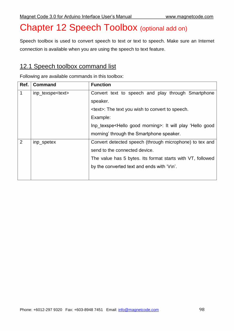
Magnet Code 3.0 for Arduino Interface User‟s Manual www.magnetcode.com
Phone: +6012-297 9320 Fax: +603-8948 7451 Email: [email protected] 98
Chapter 12 Speech Toolbox (optional add on)
Speech toolbox is used to convert speech to text or text to speech. Make sure an Internet
connection is available when you are using the speech to text feature.
12.1 Speech toolbox command list
Following are available commands in this toolbox:
Ref. Command Function
1 inp_texspe<text> Convert text to speech and play through Smartphone
speaker.
<text>: The text you wish to convert to speech.
Example:
Inp_texspe<Hello good morning>: It will play „Hello good
morning‟ through the Smartphone speaker.
2 inp_spetex Convert detected speech (through microphone) to tex and
send to the connected device.
The value has 5 bytes. Its format starts with VT, followed
by the converted text and ends with „\r\n‟.
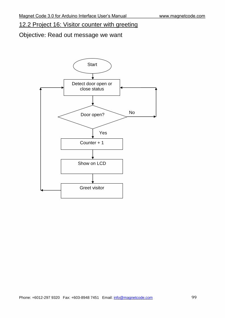
Magnet Code 3.0 for Arduino Interface User‟s Manual www.magnetcode.com
Phone: +6012-297 9320 Fax: +603-8948 7451 Email: [email protected] 99
12.2 Project 16: Visitor counter with greeting
Objective: Read out message we want
Start
Detect door open or close status
Door open? No
Yes
Show on LCD
Counter + 1
Greet visitor
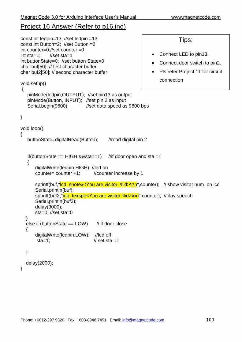
Magnet Code 3.0 for Arduino Interface User‟s Manual www.magnetcode.com
Phone: +6012-297 9320 Fax: +603-8948 7451 Email: [email protected] 100
Project 16 Answer (Refer to p16.ino) const int ledpin=13; //set ledpin =13 const int Button=2; //set Button =2 int counter=0;//set counter =0 int sta=1; //set sta=1 int buttonState=0; //set button State=0 char buf[50]; // first character buffer char buf2[50]; // second character buffer void setup() { pinMode(ledpin,OUTPUT); //set pin13 as output pinMode(Button, INPUT); //set pin 2 as input Serial.begin(9600); //set data speed as 9600 bps } void loop() { buttonState=digitalRead(Button); //read digital pin 2 If(buttonState == HIGH &&sta==1) //if door open and sta =1 { digitalWrite(ledpin,HIGH); //led on counter= counter +1; //counter increase by 1 sprintf(buf,"lcd_shotex<You are visitor: %d>\r\n",counter); // show visitor num on lcd Serial.println(buf); sprintf(buf2,"inp_texspe<You are visitor %d>\r\n",counter); //play speech Serial.println(buf2); delay(3000); sta=0; //set sta=0 } else if (buttonState == LOW) // if door close { digitalWrite(ledpin,LOW); //led off sta=1; // set sta =1 } delay(2000); }
Tips:
Connect LED to pin13.
Connect door switch to pin2.
Pls refer Project 11 for circuit
connection
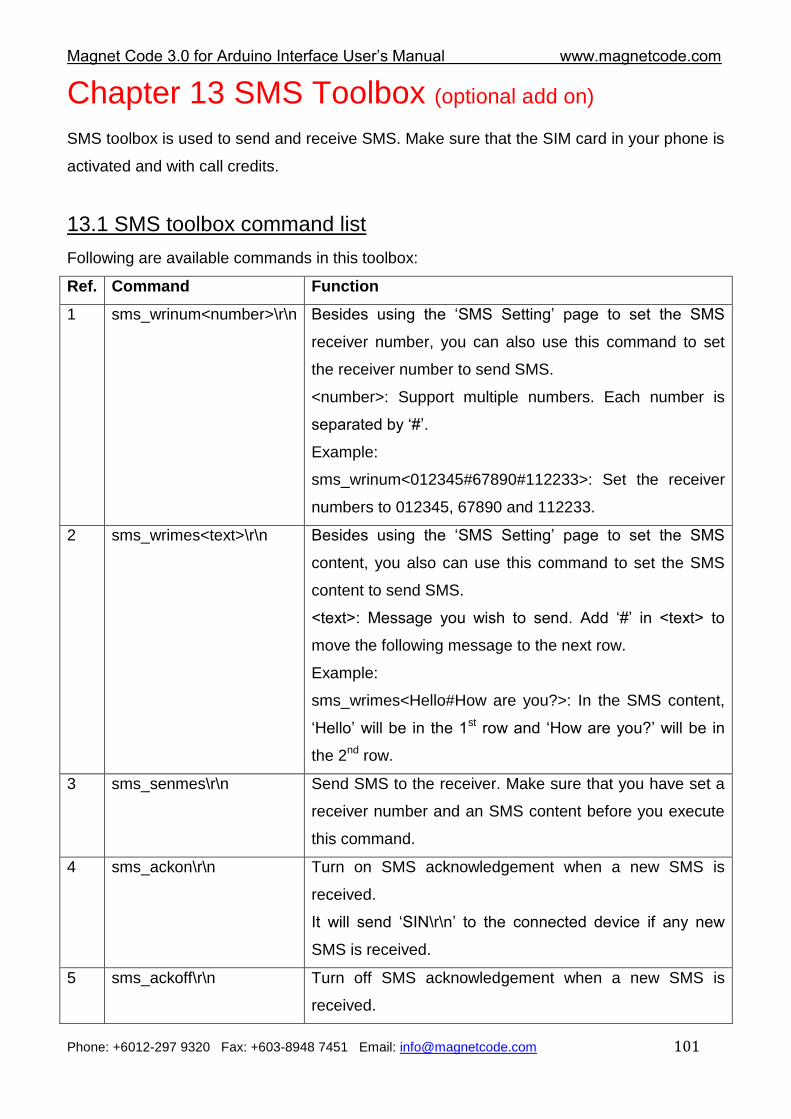
Magnet Code 3.0 for Arduino Interface User‟s Manual www.magnetcode.com
Phone: +6012-297 9320 Fax: +603-8948 7451 Email: [email protected] 101
Chapter 13 SMS Toolbox (optional add on)
SMS toolbox is used to send and receive SMS. Make sure that the SIM card in your phone is
activated and with call credits.
13.1 SMS toolbox command list
Following are available commands in this toolbox:
Ref. Command Function
1 sms_wrinum<number>\r\n Besides using the „SMS Setting‟ page to set the SMS
receiver number, you can also use this command to set
the receiver number to send SMS.
<number>: Support multiple numbers. Each number is
separated by „#‟.
Example:
sms_wrinum<012345#67890#112233>: Set the receiver
numbers to 012345, 67890 and 112233.
2 sms_wrimes<text>\r\n Besides using the „SMS Setting‟ page to set the SMS
content, you also can use this command to set the SMS
content to send SMS.
<text>: Message you wish to send. Add „#‟ in <text> to
move the following message to the next row.
Example:
sms_wrimes<Hello#How are you?>: In the SMS content,
„Hello‟ will be in the 1st row and „How are you?‟ will be in
the 2nd row.
3 sms_senmes\r\n Send SMS to the receiver. Make sure that you have set a
receiver number and an SMS content before you execute
this command.
4 sms_ackon\r\n Turn on SMS acknowledgement when a new SMS is
received.
It will send „SIN\r\n‟ to the connected device if any new
SMS is received.
5 sms_ackoff\r\n Turn off SMS acknowledgement when a new SMS is
received.
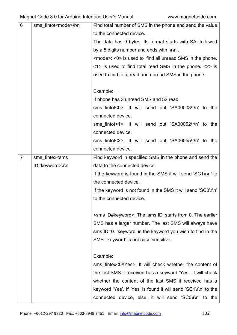
Magnet Code 3.0 for Arduino Interface User‟s Manual www.magnetcode.com
Phone: +6012-297 9320 Fax: +603-8948 7451 Email: [email protected] 102
6 sms_fintot<mode>\r\n Find total number of SMS in the phone and send the value
to the connected device.
The data has 9 bytes. Its format starts with SA, followed
by a 5 digits number and ends with „\r\n‟.
<mode>: <0> is used to find all unread SMS in the phone.
<1> is used to find total read SMS in the phone. <2> is
used to find total read and unread SMS in the phone.
Example:
If phone has 3 unread SMS and 52 read.
sms_fintot<0>: It will send out „SA00003\r\n‟ to the
connected device.
sms_fintot<1>: It will send out „SA00052\r\n‟ to the
connected device.
sms_fintot<2>: It will send out „SA00055\r\n‟ to the
connected device.
7 sms_fintex<sms
ID#keyword>\r\n
Find keyword in specified SMS in the phone and send the
data to the connected device.
If the keyword is found in the SMS it will send „SC1\r\n‟ to
the connected device.
If the keyword is not found in the SMS it will send „SC0\r\n‟
to the connected device.
<sms ID#keyword>: The „sms ID‟ starts from 0. The earlier
SMS has a larger number. The last SMS will always have
sms ID=0. „keyword‟ is the keyword you wish to find in the
SMS. „keyword‟ is not case sensitive.
Example:
sms_fintex<0#Yes>: It will check whether the content of
the last SMS it received has a keyword „Yes‟. It will check
whether the content of the last SMS it received has a
keyword „Yes‟. If „Yes‟ is found it will send „SC1\r\n‟ to the
connected device, else, it will send „SC0\r\n‟ to the
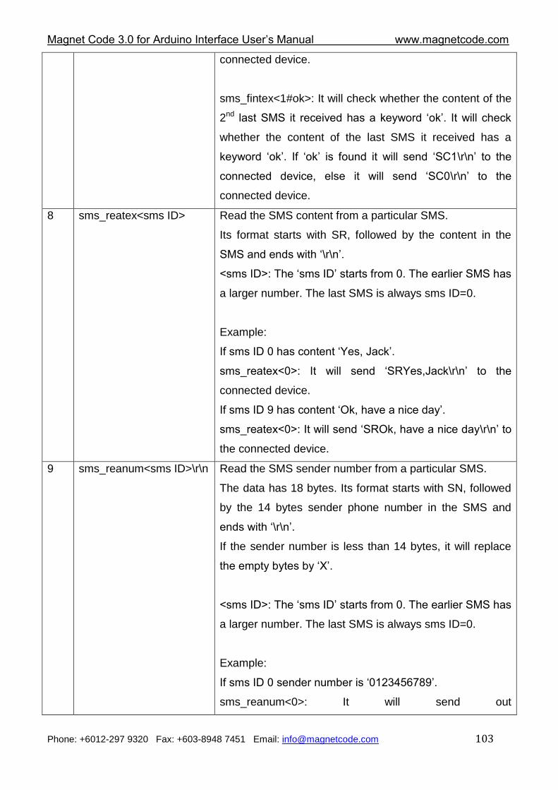
Magnet Code 3.0 for Arduino Interface User‟s Manual www.magnetcode.com
Phone: +6012-297 9320 Fax: +603-8948 7451 Email: [email protected] 103
connected device.
sms_fintex<1#ok>: It will check whether the content of the
2nd last SMS it received has a keyword „ok‟. It will check
whether the content of the last SMS it received has a
keyword „ok‟. If „ok‟ is found it will send „SC1\r\n‟ to the
connected device, else it will send „SC0\r\n‟ to the
connected device.
8 sms_reatex<sms ID> Read the SMS content from a particular SMS.
Its format starts with SR, followed by the content in the
SMS and ends with „\r\n‟.
<sms ID>: The „sms ID‟ starts from 0. The earlier SMS has
a larger number. The last SMS is always sms ID=0.
Example:
If sms ID 0 has content „Yes, Jack‟.
sms_reatex<0>: It will send „SRYes,Jack\r\n‟ to the
connected device.
If sms ID 9 has content „Ok, have a nice day‟.
sms_reatex<0>: It will send „SROk, have a nice day\r\n‟ to
the connected device.
9 sms_reanum<sms ID>\r\n Read the SMS sender number from a particular SMS.
The data has 18 bytes. Its format starts with SN, followed
by the 14 bytes sender phone number in the SMS and
ends with „\r\n‟.
If the sender number is less than 14 bytes, it will replace
the empty bytes by „X‟.
<sms ID>: The „sms ID‟ starts from 0. The earlier SMS has
a larger number. The last SMS is always sms ID=0.
Example:
If sms ID 0 sender number is „0123456789‟.
sms_reanum<0>: It will send out
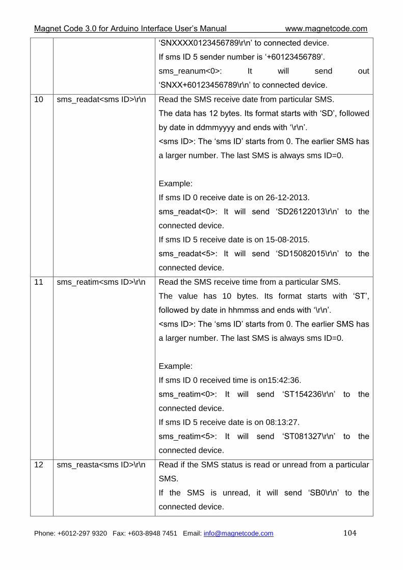
Magnet Code 3.0 for Arduino Interface User‟s Manual www.magnetcode.com
Phone: +6012-297 9320 Fax: +603-8948 7451 Email: [email protected] 104
„SNXXXX0123456789\r\n‟ to connected device.
If sms ID 5 sender number is „+60123456789‟.
sms_reanum<0>: It will send out
„SNXX+60123456789\r\n‟ to connected device.
10 sms_readat<sms ID>\r\n Read the SMS receive date from particular SMS.
The data has 12 bytes. Its format starts with „SD‟, followed
by date in ddmmyyyy and ends with „\r\n‟.
<sms ID>: The „sms ID‟ starts from 0. The earlier SMS has
a larger number. The last SMS is always sms ID=0.
Example:
If sms ID 0 receive date is on 26-12-2013.
sms_readat<0>: It will send „SD26122013\r\n‟ to the
connected device.
If sms ID 5 receive date is on 15-08-2015.
sms_readat<5>: It will send „SD15082015\r\n‟ to the
connected device.
11 sms_reatim<sms ID>\r\n Read the SMS receive time from a particular SMS.
The value has 10 bytes. Its format starts with „ST‟,
followed by date in hhmmss and ends with „\r\n‟.
<sms ID>: The „sms ID‟ starts from 0. The earlier SMS has
a larger number. The last SMS is always sms ID=0.
Example:
If sms ID 0 received time is on15:42:36.
sms_reatim<0>: It will send „ST154236\r\n‟ to the
connected device.
If sms ID 5 receive date is on 08:13:27.
sms_reatim<5>: It will send „ST081327\r\n‟ to the
connected device.
12 sms_reasta<sms ID>\r\n Read if the SMS status is read or unread from a particular
SMS.
If the SMS is unread, it will send „SB0\r\n‟ to the
connected device.
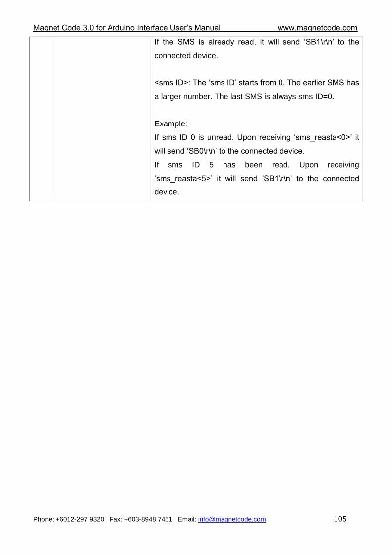
Magnet Code 3.0 for Arduino Interface User‟s Manual www.magnetcode.com
Phone: +6012-297 9320 Fax: +603-8948 7451 Email: [email protected] 105
If the SMS is already read, it will send „SB1\r\n‟ to the
connected device.
<sms ID>: The „sms ID‟ starts from 0. The earlier SMS has
a larger number. The last SMS is always sms ID=0.
Example:
If sms ID 0 is unread. Upon receiving „sms_reasta<0>‟ it
will send „SB0\r\n‟ to the connected device.
If sms ID 5 has been read. Upon receiving
„sms_reasta<5>‟ it will send „SB1\r\n‟ to the connected
device.
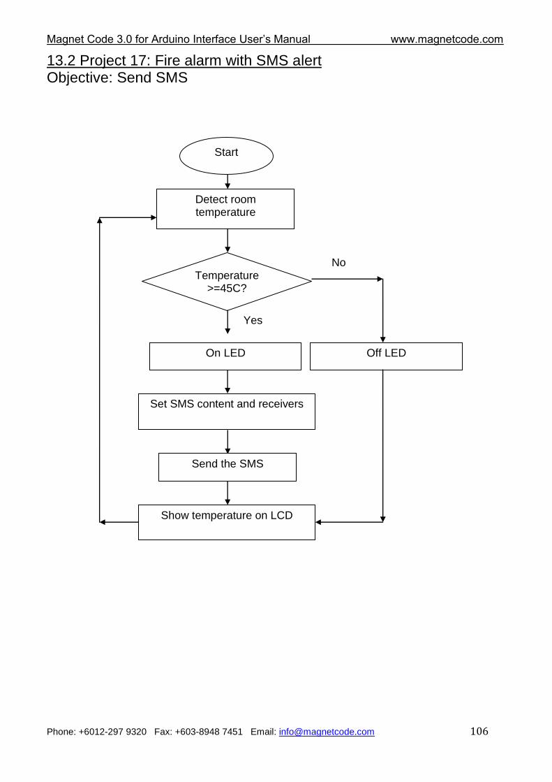
Magnet Code 3.0 for Arduino Interface User‟s Manual www.magnetcode.com
Phone: +6012-297 9320 Fax: +603-8948 7451 Email: [email protected] 106
13.2 Project 17: Fire alarm with SMS alert Objective: Send SMS
Start
Detect room temperature
Temperature >=45C?
No
Yes
Set SMS content and receivers
Send the SMS
Show temperature on LCD
On LED Off LED
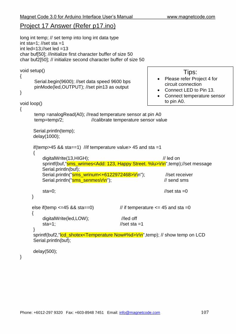
Magnet Code 3.0 for Arduino Interface User‟s Manual www.magnetcode.com
Phone: +6012-297 9320 Fax: +603-8948 7451 Email: [email protected] 107
Project 17 Answer (Refer p17.ino) long int temp; // set temp into long int data type int sta=1; //set sta =1 int led=13;//set led =13 char buf[50]; //initialize first character buffer of size 50 char buf2[50]; // initialize second character buffer of size 50 void setup() { Serial.begin(9600); //set data speed 9600 bps pinMode(led,OUTPUT); //set pin13 as output } void loop() { temp =analogRead(A0); //read temperature sensor at pin A0 temp=temp/2; //calibrate temperature sensor value Serial.println(temp); delay(1000); if(temp>45 && sta==1) //if temperature value> 45 and sta =1 { digitalWrite(13,HIGH); // led on sprintf(buf,"sms_wrimes<Add: 123, Happy Street. %lu>\r\n",temp);//set message Serial.println(buf); Serial.println("sms_wrinum<+6122972468>\r\n"); //set receiver Serial.println("sms_senmes\r\n"); // send sms sta=0; //set sta =0 } else if(temp <=45 && sta==0) // if temperature <= 45 and sta =0 { digitalWrite(led,LOW); //led off sta=1; //set sta =1 } sprintf(buf2,"lcd_shotex<Temperature Now#%d>\r\n",temp); // show temp on LCD Serial.println(buf);
delay(500); }
Tips: Please refer Project 4 for
circuit connection
Connect LED to Pin 13.
Connect temperature sensor to pin A0.
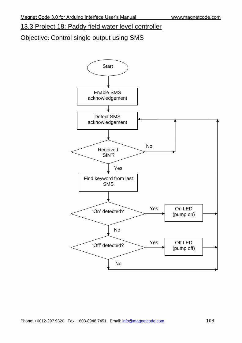
Magnet Code 3.0 for Arduino Interface User‟s Manual www.magnetcode.com
Phone: +6012-297 9320 Fax: +603-8948 7451 Email: [email protected] 108
13.3 Project 18: Paddy field water level controller
Objective: Control single output using SMS
Start
Detect SMS acknowledgement
Received „SIN‟?
No
Yes
Find keyword from last SMS
Enable SMS acknowledgement
„On‟ detected?
No
„Off‟ detected?
No
On LED (pump on)
Off LED (pump off)
Yes
Yes
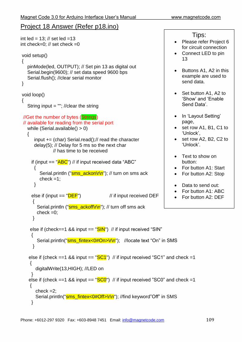
Magnet Code 3.0 for Arduino Interface User‟s Manual www.magnetcode.com
Phone: +6012-297 9320 Fax: +603-8948 7451 Email: [email protected] 109
Project 18 Answer (Refer p18.ino) int led = 13; // set led =13 int check=0; // set check =0 void setup() { pinMode(led, OUTPUT); // Set pin 13 as digital out Serial.begin(9600); // set data speed 9600 bps Serial.flush(); //clear serial monitor } void loop() { String input = ""; //clear the string //Get the number of bytes (Strings) // available for reading from the serial port while (Serial.available() > 0) { input += (char) Serial.read();// read the character delay(5); // Delay for 5 ms so the next char // has time to be received if (input == "ABC") // if input received data “ABC” { Serial.println ("sms_ackon\r\n"); // turn on sms ack check =1; } else if (input == "DEF") // if input received DEF { Serial.println ("sms_ackoff\r\n"); // turn off sms ack check =0; } else if (check==1 && input == "SIN") // if input received “SIN” { Serial.println("sms_fintex<0#On>\r\n"); //locate text “On” in SMS } else if (check ==1 && input == "SC1") // if input received “SC1” and check =1 { digitalWrite(13,HIGH); //LED on } else if (check ==1 && input == "SC0") // if input received ”SC0” and check =1 { check =2; Serial.println("sms_fintex<0#Off>\r\n"); //find keyword”Off” in SMS }
Tips: Please refer Project 6
for circuit connection
Connect LED to pin 13
Buttons A1, A2 in this example are used to send data.
Set button A1, A2 to „Show‟ and „Enable Send Data‟.
In „Layout Setting‟ page,
set row A1, B1, C1 to „Unlock‟,
set row A2, B2, C2 to „Unlock‟.
Text to show on button:
For button A1: Start
For button A2: Stop
Data to send out:
For button A1: ABC
For button A2: DEF
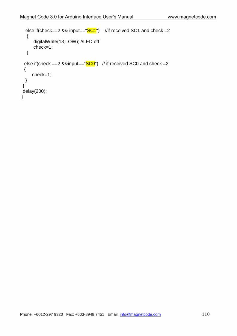
Magnet Code 3.0 for Arduino Interface User‟s Manual www.magnetcode.com
Phone: +6012-297 9320 Fax: +603-8948 7451 Email: [email protected] 110
else if(check==2 && input=="SC1") //if received SC1 and check =2 {
digitalWrite(13,LOW); //LED off check=1; } else if(check ==2 &&input=="SC0") // if received SC0 and check =2 { check=1; } } delay(200); }
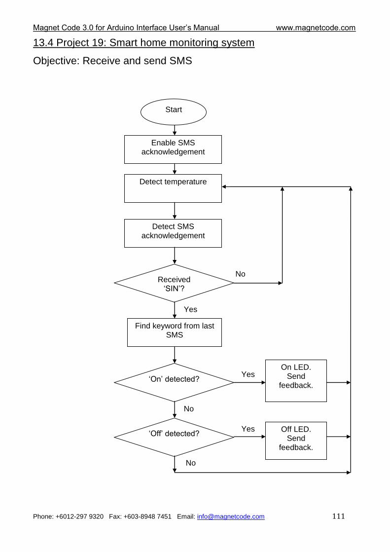
Magnet Code 3.0 for Arduino Interface User‟s Manual www.magnetcode.com
Phone: +6012-297 9320 Fax: +603-8948 7451 Email: [email protected] 111
13.4 Project 19: Smart home monitoring system
Objective: Receive and send SMS
Start
Detect SMS acknowledgement
Received „SIN‟?
No
Yes
Find keyword from last SMS
Enable SMS acknowledgement
„On‟ detected?
No
„Off‟ detected?
No
On LED. Send
feedback.
Off LED. Send
feedback.
Yes
Yes
Detect temperature
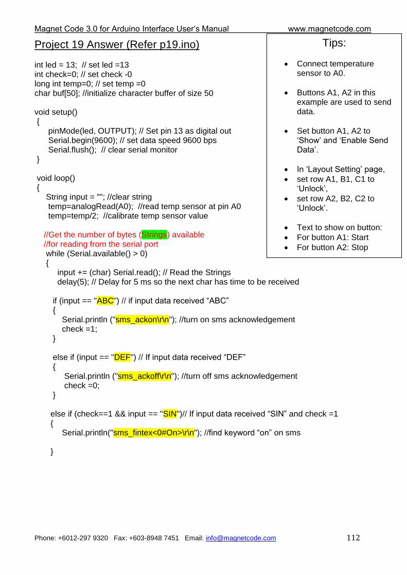
Magnet Code 3.0 for Arduino Interface User‟s Manual www.magnetcode.com
Phone: +6012-297 9320 Fax: +603-8948 7451 Email: [email protected] 112
Project 19 Answer (Refer p19.ino) int led = 13; // set led =13 int check=0; // set check -0 long int temp=0; // set temp =0 char buf[50]; //initialize character buffer of size 50 void setup() { pinMode(led, OUTPUT); // Set pin 13 as digital out Serial.begin(9600); // set data speed 9600 bps Serial.flush(); // clear serial monitor } void loop() { String input = ""; //clear string temp=analogRead(A0); //read temp sensor at pin A0 temp=temp/2; //calibrate temp sensor value
//Get the number of bytes (Strings) available //for reading from the serial port
while (Serial.available() > 0) { input += (char) Serial.read(); // Read the Strings delay(5); // Delay for 5 ms so the next char has time to be received if (input == "ABC") // if input data received “ABC” { Serial.println ("sms_ackon\r\n"); //turn on sms acknowledgement check =1; } else if (input == "DEF") // If input data received “DEF” { Serial.println ("sms_ackoff\r\n"); //turn off sms acknowledgement check =0; } else if (check==1 && input == "SIN")// If input data received “SIN” and check =1 { Serial.println("sms_fintex<0#On>\r\n"); //find keyword “on” on sms }
Tips:
Connect temperature sensor to A0.
Buttons A1, A2 in this example are used to send data.
Set button A1, A2 to „Show‟ and „Enable Send Data‟.
In „Layout Setting‟ page,
set row A1, B1, C1 to „Unlock‟,
set row A2, B2, C2 to „Unlock‟.
Text to show on button:
For button A1: Start
For button A2: Stop
Data to send out:
For button A1: ABC
For button A2: DEF
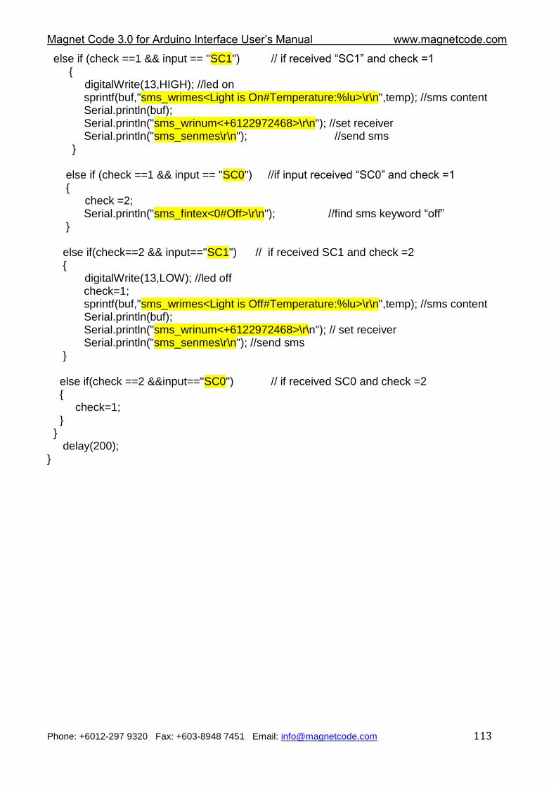
Magnet Code 3.0 for Arduino Interface User‟s Manual www.magnetcode.com
Phone: +6012-297 9320 Fax: +603-8948 7451 Email: [email protected] 113
else if (check ==1 && input == "SC1") // if received “SC1” and check =1 { digitalWrite(13,HIGH); //led on sprintf(buf,"sms_wrimes<Light is On#Temperature:%lu>\r\n",temp); //sms content Serial.println(buf); Serial.println("sms_wrinum<+6122972468>\r\n"); //set receiver Serial.println("sms_senmes\r\n"); //send sms } else if (check ==1 && input == "SC0") //if input received “SC0” and check =1 {
check =2; Serial.println("sms_fintex<0#Off>\r\n"); //find sms keyword “off” } else if(check==2 && input=="SC1") // if received SC1 and check =2 { digitalWrite(13,LOW); //led off check=1; sprintf(buf,"sms_wrimes<Light is Off#Temperature:%lu>\r\n",temp); //sms content Serial.println(buf); Serial.println("sms_wrinum<+6122972468>\r\n"); // set receiver Serial.println("sms_senmes\r\n"); //send sms } else if(check ==2 &&input=="SC0") // if received SC0 and check =2 { check=1; } } delay(200); }
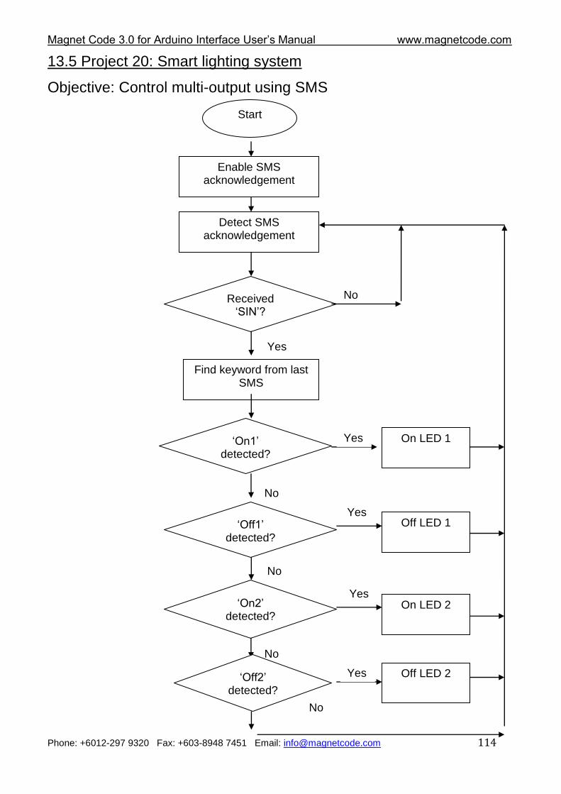
Magnet Code 3.0 for Arduino Interface User‟s Manual www.magnetcode.com
Phone: +6012-297 9320 Fax: +603-8948 7451 Email: [email protected] 114
13.5 Project 20: Smart lighting system
Objective: Control multi-output using SMS
Start
Detect SMS acknowledgement
Received „SIN‟?
No
Yes
Find keyword from last SMS
Enable SMS acknowledgement
„On1‟ detected?
No
„Off1‟ detected?
No
On LED 1
Off LED 1
Yes
Yes
„On2‟ detected?
No
„Off2‟ detected?
No
On LED 2
Off LED 2
Yes
Yes
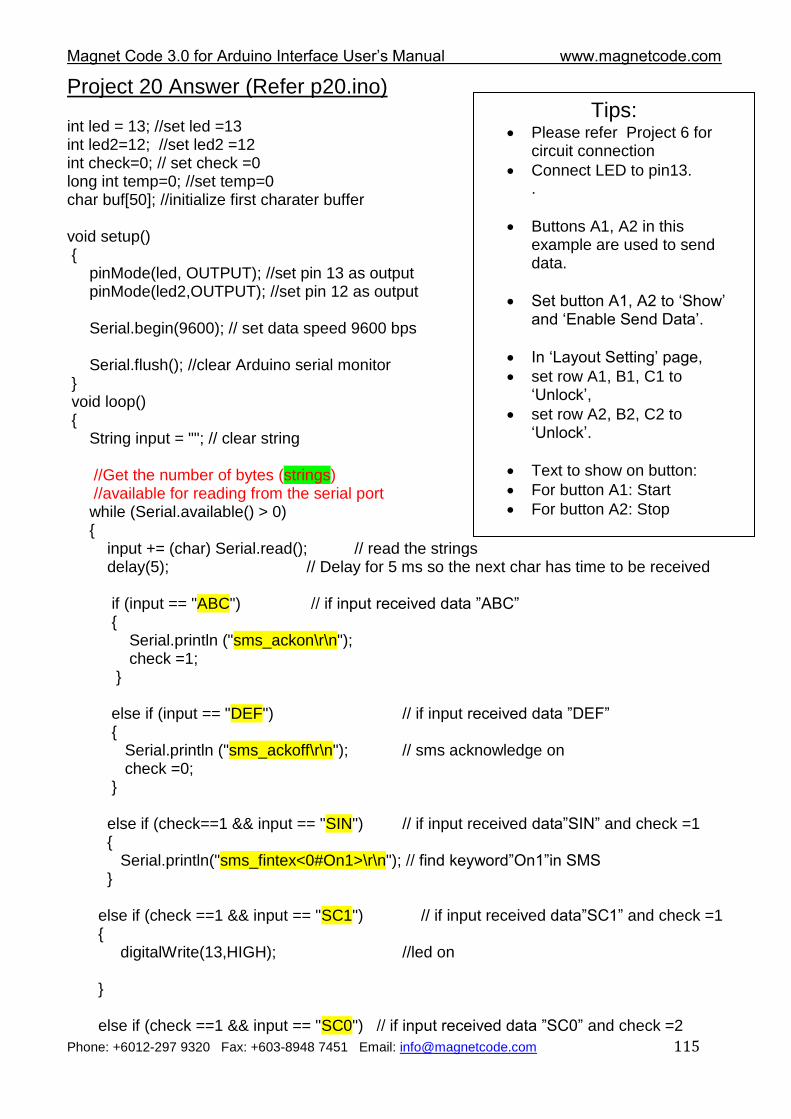
Magnet Code 3.0 for Arduino Interface User‟s Manual www.magnetcode.com
Phone: +6012-297 9320 Fax: +603-8948 7451 Email: [email protected] 115
Project 20 Answer (Refer p20.ino) int led = 13; //set led =13 int led2=12; //set led2 =12 int check=0; // set check =0 long int temp=0; //set temp=0 char buf[50]; //initialize first charater buffer void setup() { pinMode(led, OUTPUT); //set pin 13 as output pinMode(led2,OUTPUT); //set pin 12 as output Serial.begin(9600); // set data speed 9600 bps Serial.flush(); //clear Arduino serial monitor } void loop() { String input = ""; // clear string //Get the number of bytes (strings) //available for reading from the serial port while (Serial.available() > 0) { input += (char) Serial.read(); // read the strings delay(5); // Delay for 5 ms so the next char has time to be received if (input == "ABC") // if input received data ”ABC” { Serial.println ("sms_ackon\r\n"); check =1; } else if (input == "DEF") // if input received data ”DEF” { Serial.println ("sms_ackoff\r\n"); // sms acknowledge on check =0; } else if (check==1 && input == "SIN") // if input received data”SIN” and check =1 { Serial.println("sms_fintex<0#On1>\r\n"); // find keyword”On1”in SMS } else if (check ==1 && input == "SC1") // if input received data”SC1” and check =1 { digitalWrite(13,HIGH); //led on } else if (check ==1 && input == "SC0") // if input received data ”SC0” and check =2
Tips: Please refer Project 6 for
circuit connection
Connect LED to pin13. .
Buttons A1, A2 in this example are used to send data.
Set button A1, A2 to „Show‟ and „Enable Send Data‟.
In „Layout Setting‟ page,
set row A1, B1, C1 to „Unlock‟,
set row A2, B2, C2 to „Unlock‟.
Text to show on button:
For button A1: Start
For button A2: Stop
Data to send out:
For button A1: ABC
For button A2: DEF
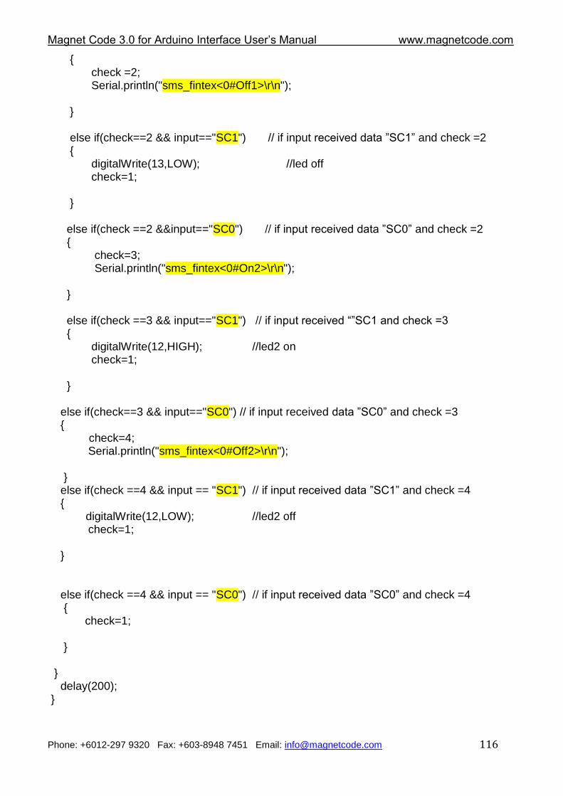
Magnet Code 3.0 for Arduino Interface User‟s Manual www.magnetcode.com
Phone: +6012-297 9320 Fax: +603-8948 7451 Email: [email protected] 116
{ check =2; Serial.println("sms_fintex<0#Off1>\r\n"); } else if(check==2 && input=="SC1") // if input received data ”SC1” and check =2 {
digitalWrite(13,LOW); //led off check=1; } else if(check ==2 &&input=="SC0") // if input received data ”SC0” and check =2 { check=3; Serial.println("sms_fintex<0#On2>\r\n"); } else if(check ==3 && input=="SC1") // if input received “”SC1 and check =3 { digitalWrite(12,HIGH); //led2 on check=1; } else if(check==3 && input=="SC0") // if input received data ”SC0” and check =3 { check=4; Serial.println("sms_fintex<0#Off2>\r\n"); } else if(check ==4 && input == "SC1") // if input received data ”SC1” and check =4 { digitalWrite(12,LOW); //led2 off check=1; } else if(check ==4 && input == "SC0") // if input received data ”SC0” and check =4
{ check=1;
} } delay(200); }
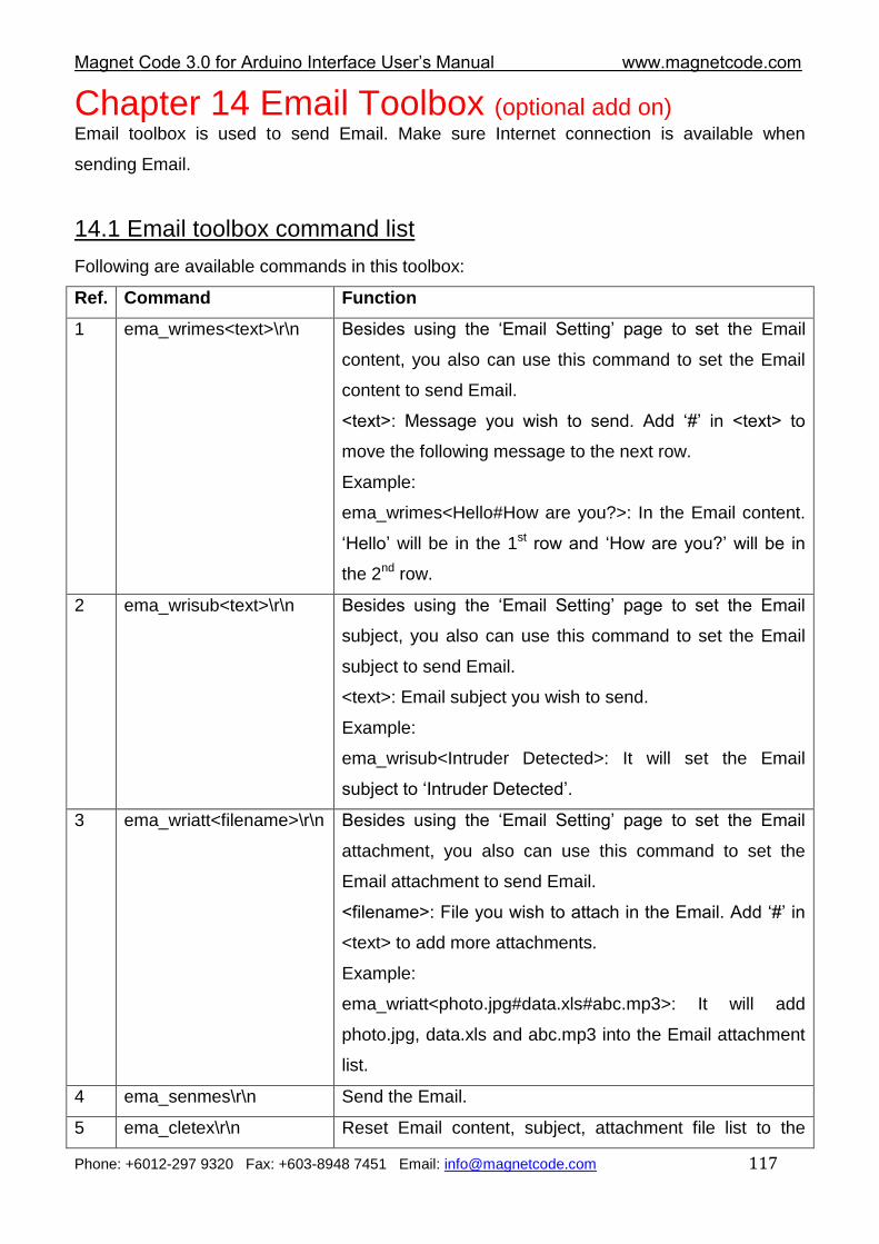
Magnet Code 3.0 for Arduino Interface User‟s Manual www.magnetcode.com
Phone: +6012-297 9320 Fax: +603-8948 7451 Email: [email protected] 117
Chapter 14 Email Toolbox (optional add on)
Email toolbox is used to send Email. Make sure Internet connection is available when
sending Email.
14.1 Email toolbox command list
Following are available commands in this toolbox:
Ref. Command Function
1 ema_wrimes<text>\r\n Besides using the „Email Setting‟ page to set the Email
content, you also can use this command to set the Email
content to send Email.
<text>: Message you wish to send. Add „#‟ in <text> to
move the following message to the next row.
Example:
ema_wrimes<Hello#How are you?>: In the Email content.
„Hello‟ will be in the 1st row and „How are you?‟ will be in
the 2nd row.
2 ema_wrisub<text>\r\n Besides using the „Email Setting‟ page to set the Email
subject, you also can use this command to set the Email
subject to send Email.
<text>: Email subject you wish to send.
Example:
ema_wrisub<Intruder Detected>: It will set the Email
subject to „Intruder Detected‟.
3 ema_wriatt<filename>\r\n Besides using the „Email Setting‟ page to set the Email
attachment, you also can use this command to set the
Email attachment to send Email.
<filename>: File you wish to attach in the Email. Add „#‟ in
<text> to add more attachments.
Example:
ema_wriatt<photo.jpg#data.xls#abc.mp3>: It will add
photo.jpg, data.xls and abc.mp3 into the Email attachment
list.
4 ema_senmes\r\n Send the Email.
5 ema_cletex\r\n Reset Email content, subject, attachment file list to the
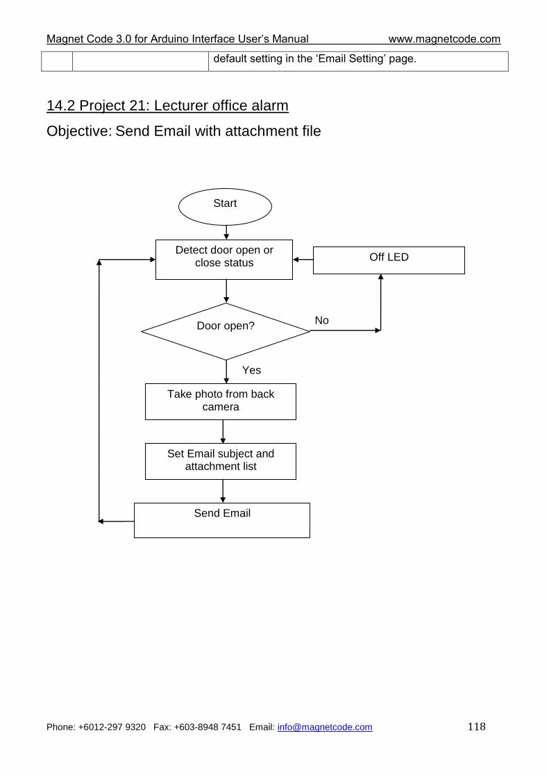
Magnet Code 3.0 for Arduino Interface User‟s Manual www.magnetcode.com
Phone: +6012-297 9320 Fax: +603-8948 7451 Email: [email protected] 118
default setting in the „Email Setting‟ page.
14.2 Project 21: Lecturer office alarm
Objective: Send Email with attachment file
Start
Detect door open or close status
Door open? No
Yes
Take photo from back camera
Set Email subject and attachment list
Send Email
Off LED
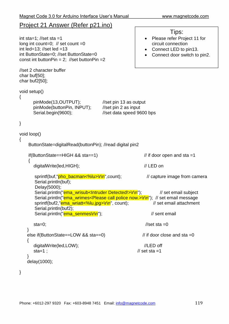
Magnet Code 3.0 for Arduino Interface User‟s Manual www.magnetcode.com
Phone: +6012-297 9320 Fax: +603-8948 7451 Email: [email protected] 119
Project 21 Answer (Refer p21.ino) int sta=1; //set sta =1 long int count=0; // set count =0 int led=13; //set led =13 int ButtonState=0; //set ButtonState=0 const int buttonPin = 2; //set buttonPin =2 //set 2 character buffer char buf[50]; char buf2[50]; void setup() { pinMode(13,OUTPUT); //set pin 13 as output pinMode(buttonPin, INPUT); //set pin 2 as input Serial.begin(9600); //set data speed 9600 bps } void loop() { ButtonState=digitalRead(buttonPin); //read digital pin2 if(ButtonState==HIGH && sta==1) // if door open and sta =1 { digitalWrite(led,HIGH); // LED on sprintf(buf,"pho_bacman<%lu>\r\n",count); // capture image from camera Serial.println(buf); Delay(5000); Serial.println("ema_wrisub<Intruder Detected!>\r\n"); // set email subject Serial.println("ema_wrimes<Please call police now.>\r\n"); // set email message sprintf(buf2,"ema_wriatt<%lu.jpg>\r\n", count); // set email attachment Serial.println(buf2); Serial.println("ema_senmes\r\n"); // sent email sta=0; //set sta =0 } else if(ButtonState==LOW && sta==0) // if door close and sta =0 { digitalWrite(led,LOW); //LED off sta=1 ; // set sta =1 } delay(1000); }
Tips: Please refer Project 11 for
circuit connection
Connect LED to pin13.
Connect door switch to pin2.
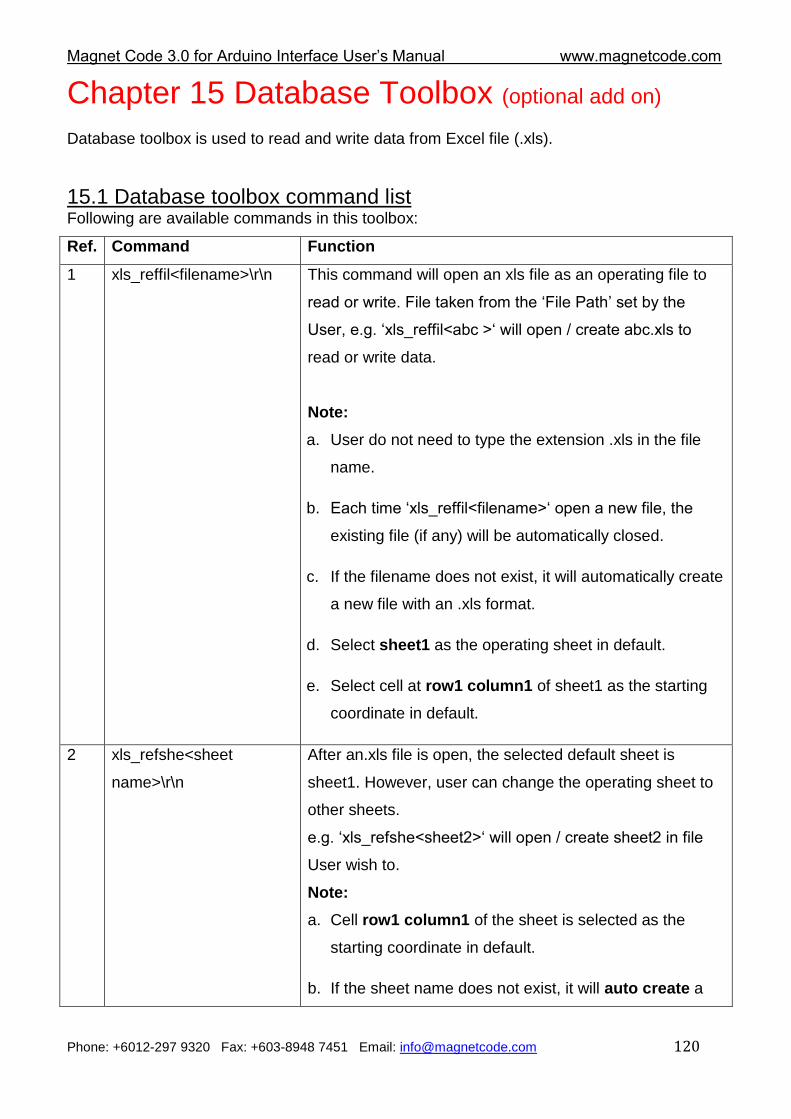
Magnet Code 3.0 for Arduino Interface User‟s Manual www.magnetcode.com
Phone: +6012-297 9320 Fax: +603-8948 7451 Email: [email protected] 120
Chapter 15 Database Toolbox (optional add on)
Database toolbox is used to read and write data from Excel file (.xls).
15.1 Database toolbox command list Following are available commands in this toolbox:
Ref. Command Function
1 xls_reffil<filename>\r\n This command will open an xls file as an operating file to
read or write. File taken from the „File Path‟ set by the
User, e.g. „xls_reffil<abc >„ will open / create abc.xls to
read or write data.
Note:
a. User do not need to type the extension .xls in the file
name.
b. Each time „xls_reffil<filename>„ open a new file, the
existing file (if any) will be automatically closed.
c. If the filename does not exist, it will automatically create
a new file with an .xls format.
d. Select sheet1 as the operating sheet in default.
e. Select cell at row1 column1 of sheet1 as the starting
coordinate in default.
2 xls_refshe<sheet
name>\r\n
After an.xls file is open, the selected default sheet is
sheet1. However, user can change the operating sheet to
other sheets.
e.g. „xls_refshe<sheet2>„ will open / create sheet2 in file
User wish to.
Note:
a. Cell row1 column1 of the sheet is selected as the
starting coordinate in default.
b. If the sheet name does not exist, it will auto create a
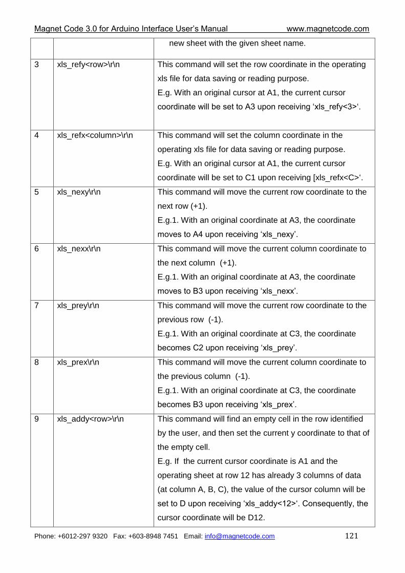
Magnet Code 3.0 for Arduino Interface User‟s Manual www.magnetcode.com
Phone: +6012-297 9320 Fax: +603-8948 7451 Email: [email protected] 121
new sheet with the given sheet name.
3 xls_refy<row>\r\n
This command will set the row coordinate in the operating
xls file for data saving or reading purpose.
E.g. With an original cursor at A1, the current cursor
coordinate will be set to A3 upon receiving „xls_refy<3>„.
4 xls_refx<column>\r\n This command will set the column coordinate in the
operating xls file for data saving or reading purpose.
E.g. With an original cursor at A1, the current cursor
coordinate will be set to C1 upon receiving [xls_refx<C>„.
5 xls_nexy\r\n
This command will move the current row coordinate to the
next row (+1).
E.g.1. With an original coordinate at A3, the coordinate
moves to A4 upon receiving „xls_nexy‟.
6 xls_nexx\r\n
This command will move the current column coordinate to
the next column (+1).
E.g.1. With an original coordinate at A3, the coordinate
moves to B3 upon receiving „xls_nexx‟.
7 xls_prey\r\n
This command will move the current row coordinate to the
previous row (-1).
E.g.1. With an original coordinate at C3, the coordinate
becomes C2 upon receiving „xls_prey‟.
8 xls_prex\r\n
This command will move the current column coordinate to
the previous column (-1).
E.g.1. With an original coordinate at C3, the coordinate
becomes B3 upon receiving „xls_prex‟.
9 xls_addy<row>\r\n
This command will find an empty cell in the row identified
by the user, and then set the current y coordinate to that of
the empty cell.
E.g. If the current cursor coordinate is A1 and the
operating sheet at row 12 has already 3 columns of data
(at column A, B, C), the value of the cursor column will be
set to D upon receiving „xls_addy<12>„. Consequently, the
cursor coordinate will be D12.
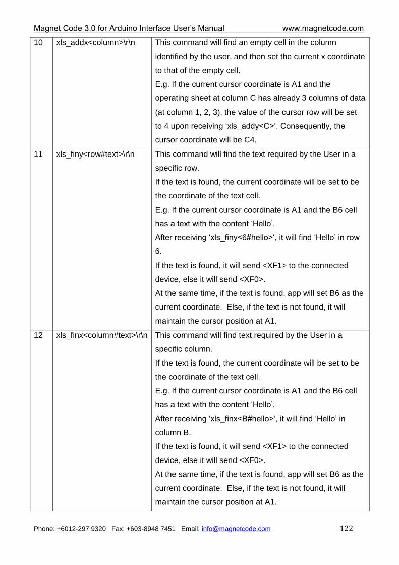
Magnet Code 3.0 for Arduino Interface User‟s Manual www.magnetcode.com
Phone: +6012-297 9320 Fax: +603-8948 7451 Email: [email protected] 122
10 xls_addx<column>\r\n This command will find an empty cell in the column
identified by the user, and then set the current x coordinate
to that of the empty cell.
E.g. If the current cursor coordinate is A1 and the
operating sheet at column C has already 3 columns of data
(at column 1, 2, 3), the value of the cursor row will be set
to 4 upon receiving „xls_addy<C>„. Consequently, the
cursor coordinate will be C4.
11 xls_finy<row#text>\r\n
This command will find the text required by the User in a
specific row.
If the text is found, the current coordinate will be set to be
the coordinate of the text cell.
E.g. If the current cursor coordinate is A1 and the B6 cell
has a text with the content „Hello‟.
After receiving „xls_finy<6#hello>„, it will find „Hello‟ in row
6.
If the text is found, it will send <XF1> to the connected
device, else it will send <XF0>.
At the same time, if the text is found, app will set B6 as the
current coordinate. Else, if the text is not found, it will
maintain the cursor position at A1.
12 xls_finx<column#text>\r\n This command will find text required by the User in a
specific column.
If the text is found, the current coordinate will be set to be
the coordinate of the text cell.
E.g. If the current cursor coordinate is A1 and the B6 cell
has a text with the content „Hello‟.
After receiving „xls_finx<B#hello>„, it will find „Hello‟ in
column B.
If the text is found, it will send <XF1> to the connected
device, else it will send <XF0>.
At the same time, if the text is found, app will set B6 as the
current coordinate. Else, if the text is not found, it will
maintain the cursor position at A1.
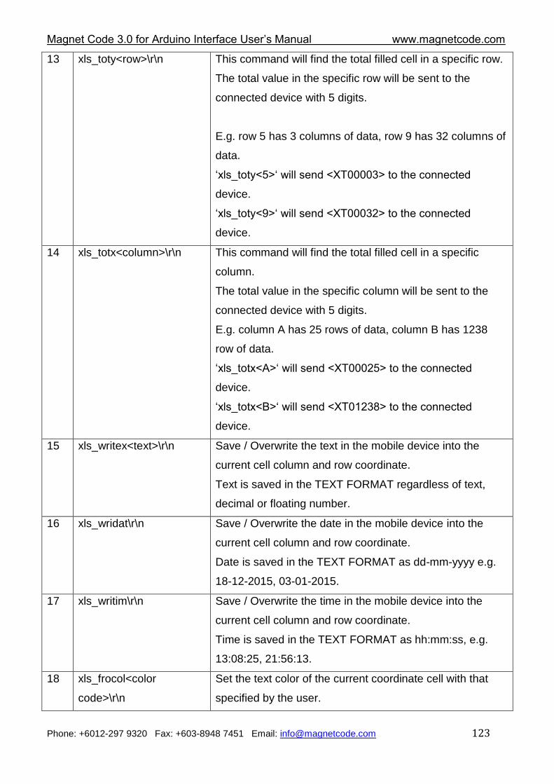
Magnet Code 3.0 for Arduino Interface User‟s Manual www.magnetcode.com
Phone: +6012-297 9320 Fax: +603-8948 7451 Email: [email protected] 123
13 xls_toty<row>\r\n
This command will find the total filled cell in a specific row.
The total value in the specific row will be sent to the
connected device with 5 digits.
E.g. row 5 has 3 columns of data, row 9 has 32 columns of
data.
„xls_toty<5>„ will send <XT00003> to the connected
device.
„xls_toty<9>„ will send <XT00032> to the connected
device.
14 xls_totx<column>\r\n
This command will find the total filled cell in a specific
column.
The total value in the specific column will be sent to the
connected device with 5 digits.
E.g. column A has 25 rows of data, column B has 1238
row of data.
„xls_totx<A>„ will send <XT00025> to the connected
device.
„xls_totx<B>„ will send <XT01238> to the connected
device.
15 xls_writex<text>\r\n Save / Overwrite the text in the mobile device into the
current cell column and row coordinate.
Text is saved in the TEXT FORMAT regardless of text,
decimal or floating number.
16 xls_wridat\r\n Save / Overwrite the date in the mobile device into the
current cell column and row coordinate.
Date is saved in the TEXT FORMAT as dd-mm-yyyy e.g.
18-12-2015, 03-01-2015.
17 xls_writim\r\n Save / Overwrite the time in the mobile device into the
current cell column and row coordinate.
Time is saved in the TEXT FORMAT as hh:mm:ss, e.g.
13:08:25, 21:56:13.
18 xls_frocol<color
code>\r\n
Set the text color of the current coordinate cell with that
specified by the user.
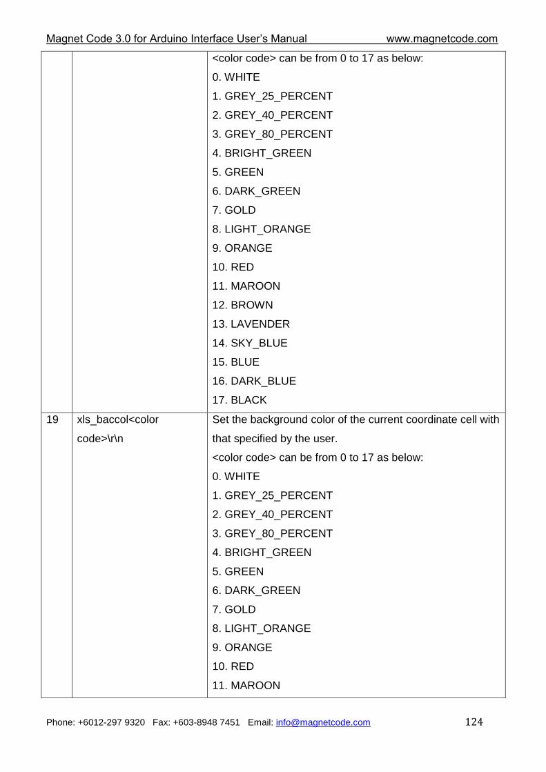
Magnet Code 3.0 for Arduino Interface User‟s Manual www.magnetcode.com
Phone: +6012-297 9320 Fax: +603-8948 7451 Email: [email protected] 124
<color code> can be from 0 to 17 as below:
0. WHITE
1. GREY_25_PERCENT
2. GREY_40_PERCENT
3. GREY_80_PERCENT
4. BRIGHT_GREEN
5. GREEN
6. DARK_GREEN
7. GOLD
8. LIGHT_ORANGE
9. ORANGE
10. RED
11. MAROON
12. BROWN
13. LAVENDER
14. SKY_BLUE
15. BLUE
16. DARK_BLUE
17. BLACK
19 xls_baccol<color
code>\r\n
Set the background color of the current coordinate cell with
that specified by the user.
<color code> can be from 0 to 17 as below:
0. WHITE
1. GREY_25_PERCENT
2. GREY_40_PERCENT
3. GREY_80_PERCENT
4. BRIGHT_GREEN
5. GREEN
6. DARK_GREEN
7. GOLD
8. LIGHT_ORANGE
9. ORANGE
10. RED
11. MAROON
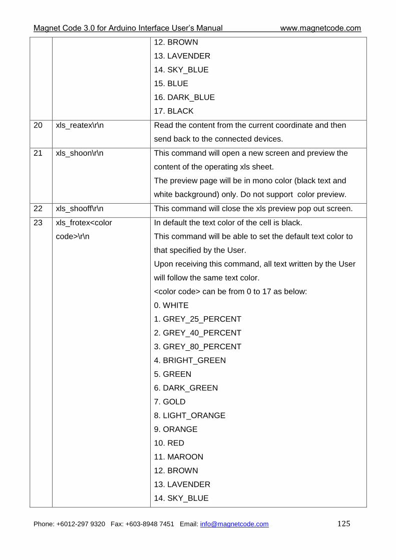
Magnet Code 3.0 for Arduino Interface User‟s Manual www.magnetcode.com
Phone: +6012-297 9320 Fax: +603-8948 7451 Email: [email protected] 125
12. BROWN
13. LAVENDER
14. SKY_BLUE
15. BLUE
16. DARK_BLUE
17. BLACK
20 xls_reatex\r\n Read the content from the current coordinate and then
send back to the connected devices.
21 xls_shoon\r\n
This command will open a new screen and preview the
content of the operating xls sheet.
The preview page will be in mono color (black text and
white background) only. Do not support color preview.
22 xls_shooff\r\n This command will close the xls preview pop out screen.
23 xls_frotex<color
code>\r\n
In default the text color of the cell is black.
This command will be able to set the default text color to
that specified by the User.
Upon receiving this command, all text written by the User
will follow the same text color.
<color code> can be from 0 to 17 as below:
0. WHITE
1. GREY_25_PERCENT
2. GREY_40_PERCENT
3. GREY_80_PERCENT
4. BRIGHT_GREEN
5. GREEN
6. DARK_GREEN
7. GOLD
8. LIGHT_ORANGE
9. ORANGE
10. RED
11. MAROON
12. BROWN
13. LAVENDER
14. SKY_BLUE
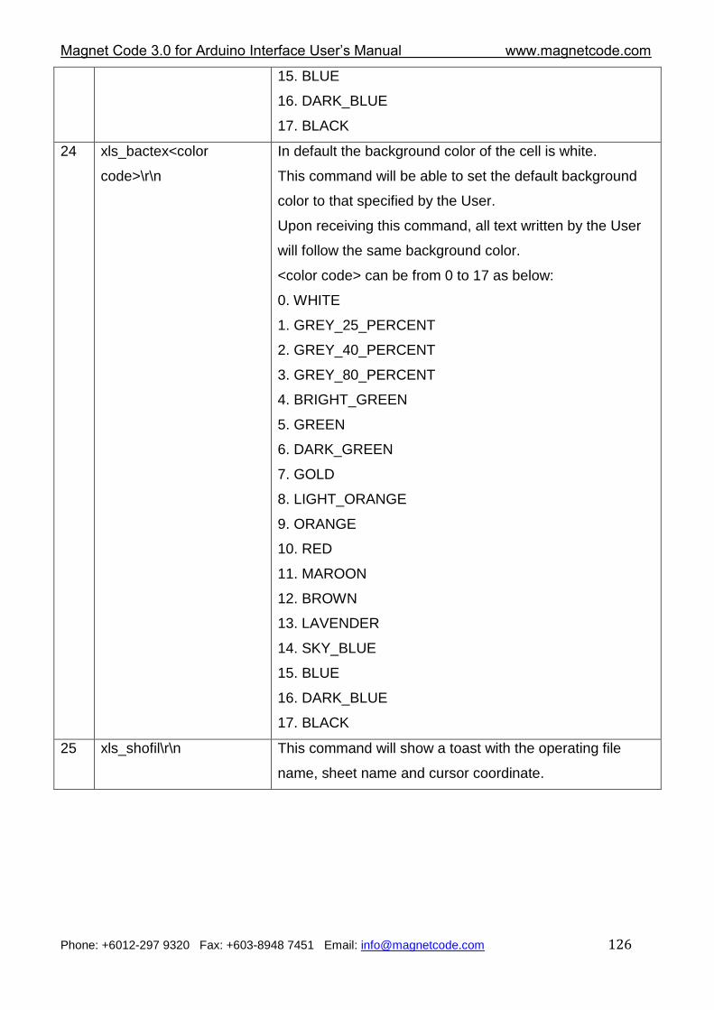
Magnet Code 3.0 for Arduino Interface User‟s Manual www.magnetcode.com
Phone: +6012-297 9320 Fax: +603-8948 7451 Email: [email protected] 126
15. BLUE
16. DARK_BLUE
17. BLACK
24 xls_bactex<color
code>\r\n
In default the background color of the cell is white.
This command will be able to set the default background
color to that specified by the User.
Upon receiving this command, all text written by the User
will follow the same background color.
<color code> can be from 0 to 17 as below:
0. WHITE
1. GREY_25_PERCENT
2. GREY_40_PERCENT
3. GREY_80_PERCENT
4. BRIGHT_GREEN
5. GREEN
6. DARK_GREEN
7. GOLD
8. LIGHT_ORANGE
9. ORANGE
10. RED
11. MAROON
12. BROWN
13. LAVENDER
14. SKY_BLUE
15. BLUE
16. DARK_BLUE
17. BLACK
25 xls_shofil\r\n This command will show a toast with the operating file
name, sheet name and cursor coordinate.
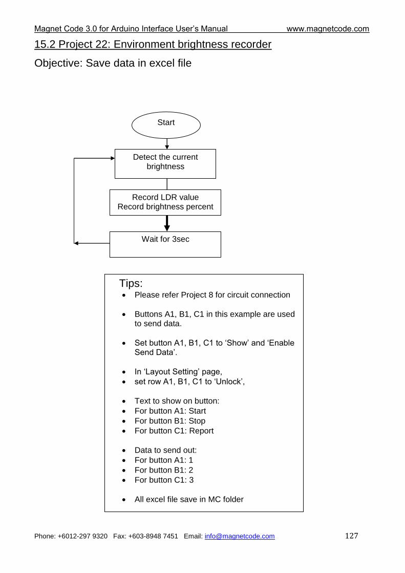
Magnet Code 3.0 for Arduino Interface User‟s Manual www.magnetcode.com
Phone: +6012-297 9320 Fax: +603-8948 7451 Email: [email protected] 127
15.2 Project 22: Environment brightness recorder
Objective: Save data in excel file
Start
Detect the current brightness
Record LDR value Record brightness percent
Wait for 3sec
Tips: Please refer Project 8 for circuit connection
Buttons A1, B1, C1 in this example are used to send data.
Set button A1, B1, C1 to „Show‟ and „Enable Send Data‟.
In „Layout Setting‟ page,
set row A1, B1, C1 to „Unlock‟,
Text to show on button:
For button A1: Start
For button B1: Stop
For button C1: Report
Data to send out:
For button A1: 1
For button B1: 2
For button C1: 3
All excel file save in MC folder
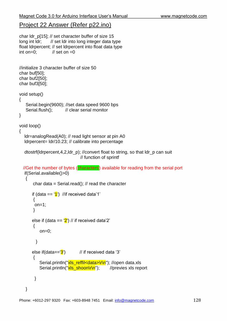
Magnet Code 3.0 for Arduino Interface User‟s Manual www.magnetcode.com
Phone: +6012-297 9320 Fax: +603-8948 7451 Email: [email protected] 128
Project 22 Answer (Refer p22.ino) char ldr_p[15]; // set character buffer of size 15 long int ldr; // set ldr into long integer data type float ldrpercent; // set ldrpercent into float data type int on=0; // set on =0 //initialize 3 character buffer of size 50 char buf[50]; char buf2[50]; char buf3[50]; void setup() { Serial.begin(9600); //set data speed 9600 bps Serial.flush(); // clear serial monitor } void loop() { ldr=analogRead(A0); // read light sensor at pin A0 ldrpercent= ldr/10.23; // calibrate into percentage dtostrf(ldrpercent,4,2,ldr_p); //convert float to string, so that ldr_p can suit // function of sprintf //Get the number of bytes (characters) available for reading from the serial port if(Serial.available()>0) { char data = Serial.read(); // read the character if (data == '1') //if received data‟1‟ { on=1; } else if (data == '2') // if received data‟2‟ { on=0; } else if(data=='3') // if received data „3‟ { Serial.println("xls_reffil<data>\r\n"); //open data.xls Serial.println("xls_shoon\r\n"); //previes xls report } }
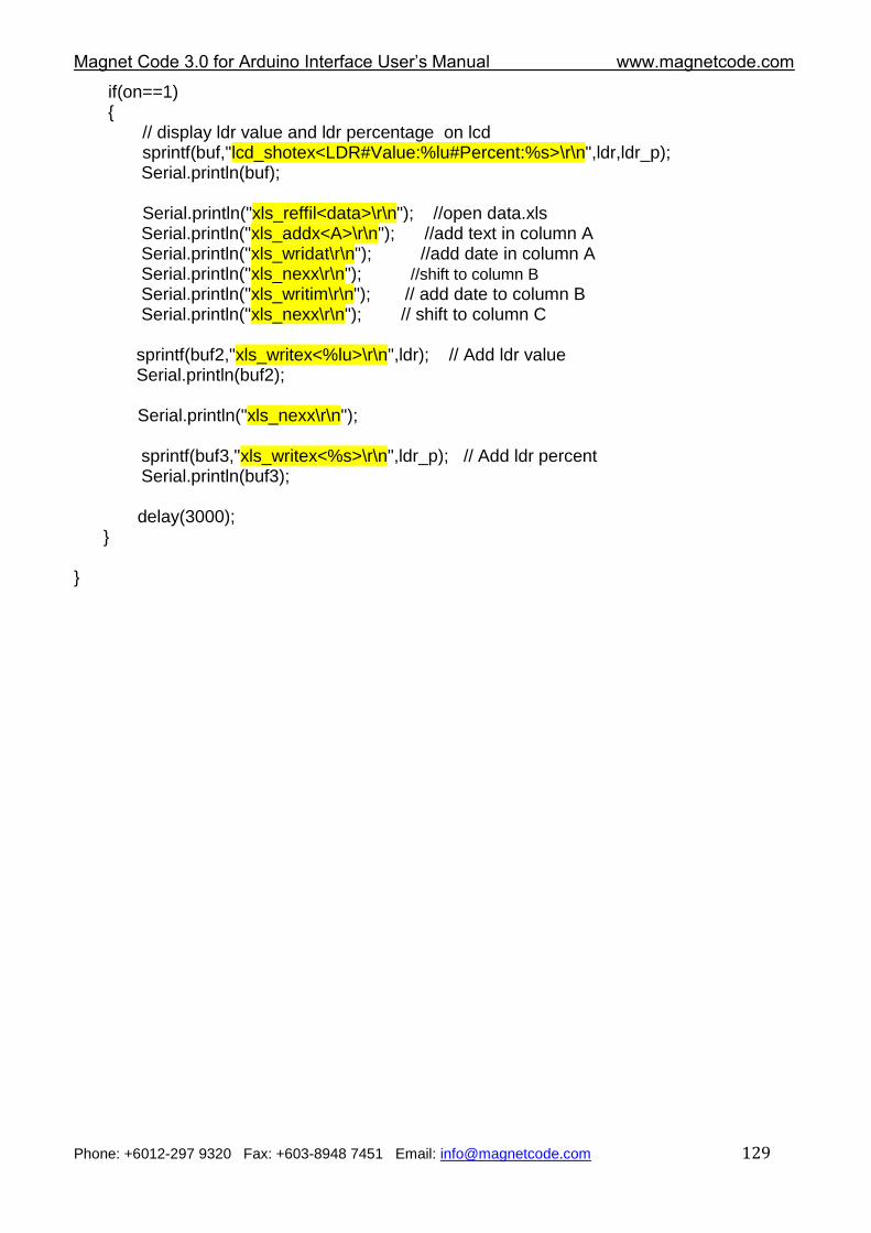
Magnet Code 3.0 for Arduino Interface User‟s Manual www.magnetcode.com
Phone: +6012-297 9320 Fax: +603-8948 7451 Email: [email protected] 129
if(on==1) { // display ldr value and ldr percentage on lcd sprintf(buf,"lcd_shotex<LDR#Value:%lu#Percent:%s>\r\n",ldr,ldr_p); Serial.println(buf); Serial.println("xls_reffil<data>\r\n"); //open data.xls Serial.println("xls_addx<A>\r\n"); //add text in column A
Serial.println("xls_wridat\r\n"); //add date in column A Serial.println("xls_nexx\r\n"); //shift to column B Serial.println("xls_writim\r\n"); // add date to column B Serial.println("xls_nexx\r\n"); // shift to column C
sprintf(buf2,"xls_writex<%lu>\r\n",ldr); // Add ldr value Serial.println(buf2); Serial.println("xls_nexx\r\n");
sprintf(buf3,"xls_writex<%s>\r\n",ldr_p); // Add ldr percent Serial.println(buf3); delay(3000); } }
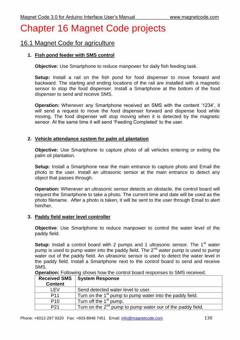
Magnet Code 3.0 for Arduino Interface User‟s Manual www.magnetcode.com
Phone: +6012-297 9320 Fax: +603-8948 7451 Email: [email protected] 130
Chapter 16 Magnet Code projects
16.1 Magnet Code for agriculture
1. Fish pond feeder with SMS control Objective: Use Smartphone to reduce manpower for daily fish feeding task. Setup: Install a rail on the fish pond for food dispenser to move forward and backward. The starting and ending locations of the rail are installed with a magnetic sensor to stop the food dispenser. Install a Smartphone at the bottom of the food dispenser to send and receive SMS. Operation: Whenever any Smartphone received an SMS with the content „1234‟, it will send a request to move the food dispenser forward and dispense food while moving. The food dispenser will stop moving when it is detected by the magnetic sensor. At the same time it will send „Feeding Completed‟ to the user.
2. Vehicle attendance system for palm oil plantation Objective: Use Smartphone to capture photo of all vehicles entering or exiting the palm oil plantation. Setup: Install a Smartphone near the main entrance to capture photo and Email the photo to the user. Install an ultrasonic sensor at the main entrance to detect any object that passes through. Operation: Whenever an ultrasonic sensor detects an obstacle, the control board will request the Smartphone to take a photo. The current time and date will be used as the photo filename. After a photo is taken, it will be sent to the user through Email to alert him/her.
3. Paddy field water level controller Objective: Use Smartphone to reduce manpower to control the water level of the paddy field. Setup: Install a control board with 2 pumps and 1 ultrasonic sensor. The 1st water pump is used to pump water into the paddy field. The 2nd water pump is used to pump water out of the paddy field. An ultrasonic sensor is used to detect the water level in the paddy field. Install a Smartphone next to the control board to send and receive SMS. Operation: Following shows how the control board responses to SMS received.
Received SMS Content
System Response
LEV Send detected water level to user.
P11 Turn on the 1st pump to pump water into the paddy field.
P10 Turn off the 1st pump.
P21 Turn on the 2nd pump to pump water our of the paddy field.
Magnet Code 3.0 for Arduino Interface User‟s Manual www.magnetcode.com
Phone: +6012-297 9320 Fax: +603-8948 7451 Email: [email protected] 131
P20 Turn off the 2nd pump.
4. Chicken farm power interruption detector Objective: Use Smartphone to alert user when power interruption for the air ventilation system is detected in the chicken farm. Setup: Connect 240Vac power supply to the control board. Install a Smartphone near the control board to send SMS. Operation: Whenever 240Vac power supply is not detected, the control board will request the Smartphone to play an audio file (e.g. siren) and send an SMS to alert the user.
5. Cowshed security system Objective: Use Smartphone to allow farmer to wirelessly monitor the inner environment of the cowshed when he is not around. Setup: Install a magnetic door switch to detect intruder. Install a Smartphone on the ceiling of the cowshed to record the inner environment. Operation: The system has an arm and disarm mode. During an arm mode, the Smartphone will play an audio file (e.g. siren) if the door is open, and record a 10-second video to be emailed to the user. Following shows how the control board responses to SMS received.
Received SMS Content
System Response
ASK Record a 10 sec video and Email the recorded video clip to the user.
ARM Arm security system.
DIS Disarm security system.
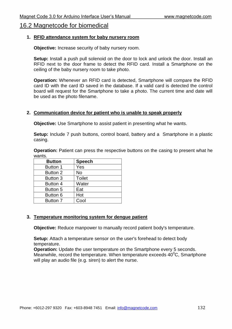
Magnet Code 3.0 for Arduino Interface User‟s Manual www.magnetcode.com
Phone: +6012-297 9320 Fax: +603-8948 7451 Email: [email protected] 132
16.2 Magnetcode for biomedical
1. RFID attendance system for baby nursery room
Objective: Increase security of baby nursery room.
Setup: Install a push pull solenoid on the door to lock and unlock the door. Install an RFID next to the door frame to detect the RFID card. Install a Smartphone on the ceiling of the baby nursery room to take photo. Operation: Whenever an RFID card is detected, Smartphone will compare the RFID card ID with the card ID saved in the database. If a valid card is detected the control board will request for the Smartphone to take a photo. The current time and date will be used as the photo filename.
2. Communication device for patient who is unable to speak properly
Objective: Use Smartphone to assist patient in presenting what he wants.
Setup: Include 7 push buttons, control board, battery and a Smartphone in a plastic casing.
Operation: Patient can press the respective buttons on the casing to present what he wants.
Button Speech
Button 1 Yes
Button 2 No
Button 3 Toilet
Button 4 Water
Button 5 Eat
Button 6 Hot
Button 7 Cool
3. Temperature monitoring system for dengue patient
Objective: Reduce manpower to manually record patient body's temperature.
Setup: Attach a temperature sensor on the user's forehead to detect body temperature. Operation: Update the user temperature on the Smartphone every 5 seconds. Meanwhile, record the temperature. When temperature exceeds 400C, Smartphone will play an audio file (e.g. siren) to alert the nurse.
Magnet Code 3.0 for Arduino Interface User‟s Manual www.magnetcode.com
Phone: +6012-297 9320 Fax: +603-8948 7451 Email: [email protected] 133
4. Step counter for rehabilitation purpose
Objective: Panel doctor can use this to monitor if his patient walks at least a required number of steps at home every day.
Setup: Install a limit switch at the bottom of the shoes. Place a Smartphone in the patient‟s pocket. Operation: Whenever a patient presses on the limit switch at the bottom of the shoes (indicate walking), the Microcontroller will up count once. The counter value will be shown on the Smartphone. When the predetermined steps (e.g. 300) are reached, the Smartphone will automatically send an SMS to inform his panel doctor.
5. Wheelchair timer for rehabilitation purpose
Objective: Avoid the user from sitting too long on a a wheelchair. Increase blood circulation to improve patients‟ recovery.
Setup: Install a light dependent resistor in the middle of the wheelchair seat. Place a Smartphone in the patient‟s pocket.
Operation: Whenever the light dependent resistor detects a dark environment (indicating that someone sits on the wheelchair), the control board will start counting down for 10 minutes (10:00). When the counter reaches 00:00, the control board will automatically request the Smartphone to vibrate and turn on the siren. After the patient stands up, the siren and vibration will stop. The cycle repeats again when the patient sits on the wheelchair.
Magnet Code 3.0 for Arduino Interface User‟s Manual www.magnetcode.com
Phone: +6012-297 9320 Fax: +603-8948 7451 Email: [email protected] 134
16.3 Magnet Code for building automation
1. Room temperature monitoring system for 3 store rooms Objective: Use Smartphone to reduce manpower to record temperature in the store room everyday. Setup: Attach temperature sensors in 3 store rooms. Operation: Control board will detect room temperature and send the detected temperature to Smartphone using Bluetooth. The temperature in the 3 rooms will be displayed on the Smartphone. Every 1 hour the system will record the detected temperature in the phone. Browse the recorded temperature anytime. If the temperature in any store room exceeds 450C, the Smartphone will vibrate and play an audio file (e.g. siren).
2. Security system for the computer lab Objective: Use Smartphone to protect CPU and monitor screen in the computer lab. Setup: Attach a limit switch below each CPU or monitor screen. Install a Smartphone on the ceiling (facing the CPU) for the purpose of taking photo. Operation: Whenever any CPU or monitor screen is taken away, the limit switch below the CPU or monitor screen will open. The Smartphone will play an audio file (e.g. siren), and record a 10-second video to be emailed to the security guard.
3. Fire alarm with SMS alert
Objective: Use Smartphone to protect building from fire.
Setup: Install a smoke sensor on the ceiling. Install a Smartphone (with SIM card and credit) in the same room to communicate with the fire alarm.
Operation: Whenever smoke is detected, the Smartphone in the room will send an SMS to the owner and the fire station with a preset SMS content. At the same time, the Smartphone will play an audio file (e.g. siren) to alert user in the room.
Magnet Code 3.0 for Arduino Interface User‟s Manual www.magnetcode.com
Phone: +6012-297 9320 Fax: +603-8948 7451 Email: [email protected] 135
4. SMS door lock
Objective: Use Smartphone to avoid lost house key cases (esp. by children).
Setup: Install a push pull solenoid on the door to lock and unlock the door. Install a electric key switch to manually lock and unlock the door. Install a Smartphone near to the control board to receive an SMS.
Operation: The door lock can be locked and unlocked using an SMS or key. Open the door using SMS. For example, when the user is not at home, the user can use SMS to unlock the door for his children who intends to enter the house after tuition without passing the key to his children. When the user is at home, he can then have an option to lock or unlock the door using the key instead of through SMS.
5. Lecturer office alarm
Objective: Use Smartphone to avoid intruder from accessing the lecturer's room.
Setup: Install PIR motion sensor in rooms. Install Smartphone on ceiling and focus its camera on the motion sensor.
Operation: Whenever the PIR motion sensor detects any motion, the Microcontroller will automatically request the Smartphone to turn on the flash light and take photos. After a photo is taken, the Smartphone will automatically email the photo to the related lecturer or security guard. The Email content will include the lecturer room's number and location.
Magnet Code 3.0 for Arduino Interface User‟s Manual www.magnetcode.com
Phone: +6012-297 9320 Fax: +603-8948 7451 Email: [email protected] 136
16.4 Magnet Code for transportation
1. Safety helmet with drowsy detection
Objective: Use Smartphone to detect drowsy motorcyclists.
Setup: Install Smartphone in the helmet. Install 3 super bright LEDs behind the helmet.
Operation: The acceleration sensor in the Smartphone will continuously monitor head tilt angle. Whenever head faces down exceeding 200, Smartphone will turn on siren and vibrate to alert the user. At the same time, the 3 super bright LEDs will keep blinking to alert the driver behind the motorcyclist.
2. Car security system with GPS coordinate detection
Objective: Use Smartphone to report the latest car coordinate when an intruder is detected.
Setup: Hide a vibration sensor and a Smartphone under the car seat..
Operation: The system has an arm and a disarm mode. User can use a key switch to select either the arm or disarm mode. During an arm mode, the Smartphone will send the latest GPS coordinate to alert the user if car vibration is detected. User can also send SMS to the security system to check the latest GPS coordinate of the car.
3. Car speed controller system
Objective: Use Smartphone to slow down the car speed when an obstacle is detected.
Setup: Install an ultrasonic sensor in front of the car. Put a Smartphone at the deskboard to alert user.
Operation: When no obstacle is detected, the driver can control the car speed him/herself. If an obstacle is detected within a 3-meter range, the car speed will be automatically slowed down and Smartphone will turn on the siren and vibrate to alert the user.
4. Traffic light failure detection system
Objective: Use Smartphone to report traffic light failure case.
Setup: Install a vibration sensor and a voltage sensor in the traffic light. Install a Smartphone on top of a nearby lamp post to report the condition of the traffic light.
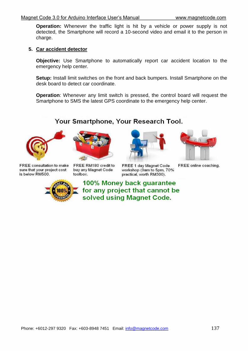
Magnet Code 3.0 for Arduino Interface User‟s Manual www.magnetcode.com
Phone: +6012-297 9320 Fax: +603-8948 7451 Email: [email protected] 137
Operation: Whenever the traffic light is hit by a vehicle or power supply is not detected, the Smartphone will record a 10-second video and email it to the person in charge.
5. Car accident detector
Objective: Use Smartphone to automatically report car accident location to the emergency help center.
Setup: Install limit switches on the front and back bumpers. Install Smartphone on the desk board to detect car coordinate.
Operation: Whenever any limit switch is pressed, the control board will request the Smartphone to SMS the latest GPS coordinate to the emergency help center.
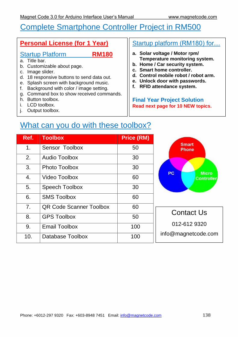
Magnet Code 3.0 for Arduino Interface User‟s Manual www.magnetcode.com
Phone: +6012-297 9320 Fax: +603-8948 7451 Email: [email protected] 138
Complete Smartphone Controller Project in RM500
What can you do with these toolbox?
Ref. Toolbox Price (RM)
1. Sensor Toolbox 50
2. Audio Toolbox 30
3. Photo Toolbox 30
4. Video Toolbox 60
5. Speech Toolbox 30
6. SMS Toolbox 60
7. QR Code Scanner Toolbox 60
8. GPS Toolbox 50
9. Email Toolbox 100
10. Database Toolbox 100
Personal License (for 1 Year)
Startup Platform RM180 a. Title bar. b. Customizable about page. c. Image slider. d. 18 responsive buttons to send data out. e. Splash screen with background music. f. Background with color / image setting. g. Command box to show received commands. h. Button toolbox. i. LCD toolbox. j. Output toolbox.
Startup platform (RM180) for…
a. Solar voltage / Motor rpm/ Temperature monitoring system.
b. Home / Car security system. c. Smart home controller. d. Control mobile robot / robot arm. e. Unlock door with passwords. f. RFID attendance system.
Final Year Project Solution Read next page for 10 NEW topics.
Contact Us
012-612 9320
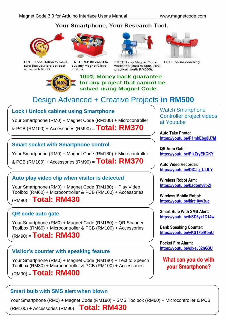
Magnet Code 3.0 for Arduino Interface User‟s Manual www.magnetcode.com
Phone: +6012-297 9320 Fax: +603-8948 7451 Email: [email protected] 139
Design Advanced + Creative Projects in RM500
QR code auto gate
Your Smartphone (RM0) + Magnet Code (RM180) + QR Scanner Toolbox (RM60) + Microcontroller & PCB (RM100) + Accessories
(RM90) = Total: RM430
Visitor’s counter with speaking feature
Your Smartphone (RM0) + Magnet Code (RM180) + Text to Speech Toolbox (RM30) + Microcontroller & PCB (RM100) + Accessories
(RM90) = Total: RM400
Smart bulb with SMS alert when blown
Your Smartphone (RM0) + Magnet Code (RM180) + SMS Toolbox (RM60) + Microcontroller & PCB
(RM100) + Accessories (RM90) = Total: RM430
Lock / Unlock cabinet using Smartphone
Your Smartphone (RM0) + Magnet Code (RM180) + Microcontroller
& PCB (RM100) + Accessories (RM90) = Total: RM370
Auto play video clip when visitor is detected
Your Smartphone (RM0) + Magnet Code (RM180) + Play Video Toolbox (RM60) + Microcontroller & PCB (RM100) + Accessories
(RM90) = Total: RM430
Smart socket with Smartphone control
Your Smartphone (RM0) + Magnet Code (RM180) + Microcontroller
& PCB (RM100) + Accessories (RM90) = Total: RM370
Watch Smartphone Controller project videos at Youtube Auto Take Photo: https://youtu.be/P1mhEbg8U7M QR Auto Gate: https://youtu.be/PikZryEKCKY Auto Video Recorder: https://youtu.be/DICJg_UL6-Y Wireless Robot Arm: https://youtu.be/badomy8t-ZI Wireless Mobile Robot: https://youtu.be/kirt10yv3uc Smart Bulb With SMS Alert: https://youtu.be/hSD6yz1C14w Bank Speaking Counter: https://youtu.be/yKS17blKbnU Pocket Fire Alarm: https://youtu.be/qlxeJ32hG3U
What can you do with your Smartphone?
Magnet Code 3.0 for Arduino Interface User‟s Manual www.magnetcode.com
Phone: +6012-297 9320 Fax: +603-8948 7451 Email: [email protected] 140
Home security system which can take intruder photo & Email user
Your Smartphone (RM0) + Magnet Code (RM180) + Photo Toolbox (RM30) + Email Toolbox
(RM100) + Microcontroller & PCB (RM100) + Accessories (RM90) = Total: RM500
Temperature & Brightness data recorder with Excel report
Your Smartphone (RM0) + Magnet Code (RM180) + Excel Toolbox (RM100) + Microcontroller & PCB
(RM100) + Accessories (RM90) = Total: RM470
Magnet Code 3.0 for Arduino Interface User‟s Manual www.magnetcode.com
Phone: +6012-297 9320 Fax: +603-8948 7451 Email: [email protected] 141
NOTE

Magnet Code 3.0 for Arduino Interface User‟s Manual www.magnetcode.com
Phone: +6012-297 9320 Fax: +603-8948 7451 Email: [email protected] 142
NOTE

Magnet Code 3.0 for Arduino Interface User‟s Manual www.magnetcode.com
Phone: +6012-297 9320 Fax: +603-8948 7451 Email: [email protected] 143
NOTE

Magnet Code 3.0 for Arduino Interface User‟s Manual www.magnetcode.com
Phone: +6012-297 9320 Fax: +603-8948 7451 Email: [email protected] 144
NOTE
Magnet Code 3.0 for Arduino Interface User‟s Manual www.magnetcode.com
Phone: +6012-297 9320 Fax: +603-8948 7451 Email: [email protected] 145
NOTE