Embed Size (px)
Citation preview
GeoSIG Ltd, Wiesenstrasse 39, 8952 Schlieren, Switzerland Phone: + 41 44 810 2150, Fax: + 41 44 810 2350
[email protected], www.geosig.com
User Manual CR-6 Central Recording System

User Manual CR-6 Central Recording System 2 / 40 12.09.2016 / V5.5
GS_CR-6_UserManual_V05
Document Revision Version Date Modification Prepared Checked Released 1 13.08.2012 First release JLT/MAE IGP/SIB MAE 2 21.09.2012 Minor corrections, new template
applied MAE IGP/SIB MAE
3 20.12.2012 Minor corrections on RS-232 connector
JLT MAE MAE
4 02.08.2013 Minor corrections on cabling JLT MAE MAE 5 12.09.2016 Addition of “GeoSIG Cybersecurity
Recommendations” section. KEC VAG VAG
Disclaimer GeoSIG Ltd reserves the right to change the information contained in this document without notice. While the information contained herein is assumed to be accurate, GeoSIG Ltd assumes no responsibility for any errors or omissions.
Copyright Notice No part of this document may be reproduced without the prior written consent of GeoSIG Ltd. Software described in this document is furnished under a license and may only be used or copied in accordance with the terms of such a license.
Trademark All brand and product names mentioned are trademarks or registered trademarks of their respective holders.
All rights reserved.
GeoSIG Ltd
Switzerland
User Manual CR-6 Central Recording System 12.09.2016 / V5.5 3 / 40
GS_CR-6_UserManual_V05
Table of Contents
Warnings and Safety ........................................................................................................... 5
GeoSIG Cybersecurity Recommendations .......................................................................... 6
Symbols and Abbreviations ................................................................................................. 8
1. Introduction ...................................................................................................................... 9
2. Incoming Inspection ......................................................................................................... 9 2.1. Damage during Shipment ....................................................................................................................... 9 2.2. Warranty ................................................................................................................................................ 10
2.2.1. Limitation of Warranty .................................................................................................................... 10 2.3. Storage (Instrument Shelf Life) ............................................................................................................. 10
2.3.1. Main battery ................................................................................................................................... 11 2.3.2. Backup battery ............................................................................................................................... 11
3. System Description ........................................................................................................ 12 3.1. 19” Industrial Computer ......................................................................................................................... 14 3.2. CR-6-BASE Base Rack and CR-6-EXT Extension Rack ...................................................................... 14
3.2.1. Front Side ...................................................................................................................................... 14 3.2.2. Back Side ....................................................................................................................................... 15
4. Slot-In Modules .............................................................................................................. 16 4.1. Front Side .............................................................................................................................................. 16
4.1.1. CR-6-WDx Watchdog Slot-In-Modules .......................................................................................... 16 4.1.2. CR-6-Dx Digitiser Slot-In Module................................................................................................... 19
4.2. Back Side .............................................................................................................................................. 20 4.2.1. CR-6-OVPSx Sensor OVP Slot-In Module .................................................................................... 20 4.2.2. CR-6-OVPx OVP Slot-In Module ................................................................................................... 22 4.2.3. CR-6-COMx Communication Slot-In-Module ................................................................................ 24
5. Installation ..................................................................................................................... 26 5.1. Site Selection ........................................................................................................................................ 26
5.1.1. Environmental Considerations ....................................................................................................... 26 5.1.2. Power Supply Considerations........................................................................................................ 26
5.2. Cabling of a CR-6-BASE ....................................................................................................................... 27 5.3. Interconnection of one or more CR-6-EXT with a CR-6-BASE ............................................................. 28
6. Configuration and Operation .......................................................................................... 29 6.1. Data Storage ......................................................................................................................................... 29
6.1.1. Data Access on a Remote Computer ............................................................................................ 29 6.2. Add new CR-6Dx Digitiser Slot-In Modules .......................................................................................... 30
6.2.1. Permanent and Event Recording .................................................................................................. 31 6.2.2. Configuration of CR-6-WDB Base Watchdog Slot-In Module ....................................................... 33
6.3. Data Streaming to Remote Computer ................................................................................................... 35 6.3.1. Settings on the Industrial Computer of the CR-6 ........................................................................... 35 6.3.2. Remote Computer Settings ........................................................................................................... 36

User Manual CR-6 Central Recording System 4 / 40 12.09.2016 / V5.5
GS_CR-6_UserManual_V05
7. Functional Description .................................................................................................... 38 7.1. Signal Conditioning................................................................................................................................38 7.2. Triggering ..............................................................................................................................................39 7.3. Clock ......................................................................................................................................................39
7.3.1. GPS Option ....................................................................................................................................39 7.3.2. Synchronisation..............................................................................................................................39
8. Maintenance .................................................................................................................. 40
Table of Figures Figure 1. Jumper location to disconnect Backup Battery for RTC................................................................... 11 Figure 2. System Overview .............................................................................................................................. 12 Figure 3. Internal Block Diagram ..................................................................................................................... 13 Figure 4. Front view of the CR-6-BASE Base Rack ........................................................................................ 14 Figure 5. Back view of the CR-6-BASE Base Rack......................................................................................... 15 Figure 6. CR-6-WDB (a) and CR-6-WDE (b) Watchdog Slot-In Module ......................................................... 16 Figure 7. Supply voltage supervision by the CR-6-WDB Module .................................................................... 18 Figure 8 CR-6-Dx Digitiser Slot-In Module ...................................................................................................... 19 Figure 9. CR-6-OVPS1 (a) and CR-6-OVPS2 (b) Sensor OVP Slot-In Module .............................................. 20 Figure 10. CR-6-OVPB (a) and CR-6-OVPE (b) OVP Slot-In Module ........................................................... 22 Figure 11. CR-6-COMB (a) and CR-6-COME (b) OVP Slot-In Module .......................................................... 24 Figure 12. External cabling of a CR-6-BASE .................................................................................................. 27 Figure 13. Interconnection of a CR-6-EXT with a CR-6-BASE ...................................................................... 28 Figure 14. Map a network drive ....................................................................................................................... 29 Figure 15. Map of the data folder from the Industrial PC module .................................................................... 30 Figure 16. Channels of Digitizers..................................................................................................................... 30 Figure 17. Setup of permanent and event recoding ........................................................................................ 31 Figure 18: Watchdogs settings of the CR-6 ..................................................................................................... 33 Figure 19. Data forwarding over Network ........................................................................................................ 35 Figure 20. Network Links ................................................................................................................................. 36 Figure 21 Remote streams .............................................................................................................................. 37

User Manual CR-6 Central Recording System 12.09.2016 / V5.5 5 / 40
GS_CR-6_UserManual_V05
Warnings and Safety a
STATIC ELECTRICITY The Instrument contains CMOS devices and when serviced, care must be taken to prevent damage due to static electricity. This is very important to ensure long term reliability of the unit.
a
BATTERY LIFE Although supplied through an AC/DC adapter from the mains, the instrument is optionally shipped with the batteries to provide the backup power supply. If the system is not in use, the batteries should be disconnected. If connected, the batteries are attached using the clamps; the red cable on "+", the black cable on “–“ poles of the battery. Note: The battery lifetime can drastically change depending on operating conditions. Strong discharge of the main battery must be avoided.
a
REPLACEMENT OF SLOT-IN-MODULES The slot-in-modules are not hot swappable. When changing any slot-in-modules, the instrument must be switched off first to avoid any damage on the instrument.

User Manual CR-6 Central Recording System 6 / 40 12.09.2016 / V5.5
GS_CR-6_UserManual_V05
GeoSIG Cybersecurity Recommendations GeoSIG instruments, as described in their documentation, have built-in security and safety features against unauthorised access or use. However, ultimately it is the user’s responsibility to ensure the safe and secure usage of our instruments based on their actual implementation. No factory delivered solution can fit each and every possible scenario. The user is advised herein that once you connect a device to a network, you are also connecting that network to that device. It is the responsibility of the user to take appropriate precautions so that all devices should be adequately hardened, such as with individual strong passwords, and should have their traffic monitored and managed via appropriate security features, such as firewalls. Also, non-critical devices should be segmented away from networks that contain sensitive information.
Compliance with a well-defined security procedure helps protect not only an individual device, but also other devices connected through the network. Such procedure would be intended to prevent exploitation of an individual device’s resources by unauthorized individuals, including the use of such device to attack other systems on the network or the Internet.
The following recommendations can be considered in establishing such a security procedure:
1. Physical access restriction
All devices must be restricted from unauthorised physical access and a well-defined physical access procedure shall be utilised.
2. No Unattended Console Sessions
Except for the devices which are physically secured, no unattended console sessions shall be left running.
3. No Unattended Network Sessions
No unattended user interface sessions shall be left running towards any device accessed through its network interface.
4. Use of a Firewall
For a network that has any connection to the outside world, a hardware firewall must be running and configured to block all inbound traffic that is not explicitly required for the intended use of the network and the connected devices. The user can also consider limiting outbound traffic.
a
Any communication ports that are required for the operation must be protected.
5. No Unnecessary Services or Ports
If a service or port is not necessary for the intended purpose or operation of the device, that service must not be running and the port must be closed. (e.g. if seedlink server is running, but not used, turn it off)
6. Use of authentication
Network and console device access must require authentication by means of strong and individualised passwords per device (no passe-partout passwords).
Wireless access must require strong encryption to associate (such as WPA2), or some other strong mechanism to keep casual users near the access point from using it to get full access to the network. WEP or MAC address restrictions do not meet this requirement.

User Manual CR-6 Central Recording System 12.09.2016 / V5.5 7 / 40
GS_CR-6_UserManual_V05
7. Password complexity and security
When passwords are used, they must meet the specifications similar to below: a
All default passwords must be changed at time of initial access or latest at deployment into service.
Passwords MUST:
contain eight characters or more
contain characters from AT LEAST two of the following three character classes:
Alphabetic (e.g., a-z, A-Z) Numeric (i.e. 0-9) Punctuation and other characters (e.g., !@#$%^&*()_+|~-=\`{}[]:";'<>?,./)
8. Privileged Accounts
Privileged and super-user accounts (Administrator, root, etc.) must not be used for non-administrator activities. A secure mechanism to escalate privileges with a standard account is acceptable to meet this requirement. Network services must run under accounts assigned the minimum necessary privileges.
9. No Unencrypted Authentication
All network-based authentication must be strongly encrypted. In particular, insecure services such as Telnet, FTP, SNMP, POP, and IMAP must not be used or must be replaced by their encrypted equivalents.
10. Software / Firmware updates
Networked devices must only run software/firmware that are updated according to supplier’s guidelines. A periodical check of any available updates from the supplier must be sought.
Please contact GeoSIG Ltd if you require any further advice or clarification.

User Manual CR-6 Central Recording System 8 / 40 12.09.2016 / V5.5
GS_CR-6_UserManual_V05
Symbols and Abbreviations CR-6-BASE Base Rack of CR-6 System CR-6-EXT Extension Rack of CR-6 System CR-6-COMB Base Communication Slot-In Module CR-6-COME Extension Communication Slot-In Module CR-6-DM Master Digitiser Slot-In Module CR-6-DS Slave Digitiser Slot-In Module CR-6-OVPB Base Over Voltage Protection Slot-In Module CR-6-OVPE Extension Over Voltage Protection Slot-In Module CR-6-OVPS Sensor Over Voltage Protection Slot-In Module CR-6-WDB Base Watchdog Slot-In Module CR-6-WDE Extension Watchdog Slot-In Module RTC Real Time Clock

User Manual CR-6 Central Recording System 12.09.2016 / V5.5 9 / 40
GS_CR-6_UserManual_V05
1. Introduction a
Dear Valued GeoSIG Customer, thank you for purchasing this product. These Instruments have been optimised to meet the requirements of the majority of customers out of the box and may have even be delivered tailored to your needs. In any case, to be able to get the most out of our product, please carefully study this manual, its appendices and referenced manuals, as well as any other documents delivered with it. This is a reliable and easy to use device, and at the same time a sophisticated product, which requires care, attention and know-how in configuring, installing, operating and maintenance.
The Central Recording System CR-6 (in further text CR-6 or instrument) is a 24 bit seismic system suitable for centralised data acquisition and recording. The CR-6 is designed for both, temporary and permanent setups such as bridges, tunnels, and tall buildings. It is easy to use and provides user with a possibility to easily reinstall the system and acquire the seismic data from numerous measurement points.
Several types of externally mounted sensors can be used with the instrument, like seismometers, geophones, accelerometers, anemometers or other sensors with single-ended or differential outputs.
The signals such as temperature are considered slow-changing and the chosen sampling rate might be the minimum one (typically a few samples per second suffice). The accelerometers, on the other side, generate the signals of a wider bandwidth and as such require higher sampling rate (typically 50 SPS or higher depending on the required bandwidth, i.e. type of the events observed at the specific site).
The CR-6 collects and records the data, which can later be downloaded and analysed on a remote PC running the dedicated software package GeoDAS. Optionally a screen and keyboard can be connected to the industrial computer of the CR-6 to configure the instrument and view the data on site.
Frequency response (bandwidth) depends on the chosen low-pass filter and the sampling rate. Typical attenuation at 99% of the Nyquist frequency is >120 dB.
During normal operation the instrument continuously amplifies, filters and converts sensor inputs to 24 bit digital form and passes these to the industrial computer. The recording parameters can be set by the computer. The recorded data can then be downloaded over the network and analysed with the GeoDAS software package.
Trigger algorithms include STA/LTA ratio triggering and level triggering. The STA/LTA ratio trigger computes the short term and long term signal averages.
This connection facilitates data acquisition and performs a complete sensors test as well via the menu driven software GeoDAS.
2. Incoming Inspection All Instruments are carefully inspected both electrically and mechanically before they leave the factory. Please check if all received items correspond to the packing list and your order confirmation. In case of discrepancies please contact GeoSIG or your local representative immediately.
2.1. Damage during Shipment
If requested at the time of order, all instruments can be insured prior to the shipment. If you receive damaged equipment and shipping insurance was previously arranged you should:
x Report the damage to your shipper immediately x Inform GeoSIG or your local representative immediately x Keep all packaging and shipping documents
A
Insurance claims may be void if the above procedure is not followed.

User Manual CR-6 Central Recording System 10 / 40 12.09.2016 / V5.5
GS_CR-6_UserManual_V05
2.2. Warranty
GeoSIG Ltd warrants hardware and software products against defects in materials, workmanship and design for the defined period in the relevant contract or offer, starting from date of shipment and 5 years parts and maintenance support commitment. If GeoSIG receives notice of such defects during the warranty period, GeoSIG shall at its option either repair (at factory) or replace free of charge hardware and software products that prove to be defective. If GeoSIG is unable, within a reasonable time to repair or replace any instrument to a condition as warranted, buyer shall be entitled to a refund of the purchase price upon return of the instrument to GeoSIG. 50 % of freight charges on shipments of warranty repairs or replacements will be borne by GeoSIG (normally one way freight).
2.2.1. Limitation of Warranty
The foregoing guarantee shall not apply to defects resulting from:
x Improper or inadequate maintenance by buyer x Buyer supplied software or interfacing x Unauthorised modification or misuse x Operation and storage outside of the environmental specifications of the instrument x Improper preparation and maintenance of site.
2.3. Storage (Instrument Shelf Life)
In case the instrument is stored, the batteries have to be maintained according to the storage duration.
Period of time
External power supply
Instrument is operating
Main battery Real Time Clock backup battery
< 1 month ON YES Connected Connected
ON NO Connected Connected
OFF NO Connected Connected 1 – 3
months ON YES Connected Connected
ON NO Connected Connected
OFF NO Disconnected Connected 3 – 6
months ON YES Connected Connected
ON NO Connected Disconnected
OFF NO Disconnected Disconnected More than 6
months ON YES Connected Connected
ON NO Connected Disconnected
OFF NO Disconnected, must be recharged every 6 months for at least
24 hours.
Disconnected
See chapter 2.3.2 to see how to disconnect and connect the backup battery

User Manual CR-6 Central Recording System 12.09.2016 / V5.5 11 / 40
GS_CR-6_UserManual_V05
2.3.1. Main battery
The instrument is normally connected to a 100 Ah battery, which is charged through a separate power supply module.
2.3.2. Backup battery
The Real Time Clock (RTC) of the CR-6 Recording System is located on the CR-6-DM Master Digitiser Slot-In Module. The autonomy of the RTC on its backup battery is 3 years typical at ambient temperature. To disconnect this backup battery, the jumper JMP_BBATT on the CR-6-DM Master Digitiser Slot-In Module has to be put in position 2-3.
Figure 1. Jumper location to disconnect Backup Battery for RTC

User Manual CR-6 Central Recording System 12 / 40 12.09.2016 / V5.5
GS_CR-6_UserManual_V05
3. System Description The CR-6 is a multi-channel central recording system mounted in a 19” rack and containing of an industrial computer and one or several digitiser racks. Each rack contains up to 32 channels and several racks can be mounted on top of each other.
Figure 2. System Overview
The GPS module provides an accurate time source to the CR-6 Recording System. The CR-6 system locks the internal RTC with the GPS time source. If GPS is lost, the internal RTC signal will reproduce the 1PPS signal and run for itself keeping all the channels synchronised.
The CR-6 system can manage up to 36 channels per digitiser rack module and contains an OVP protection on all in and outputs. A wide variety of sensors can be used: acceleration, velocity, displacement, temperature, current, wind speed, wind direction, stress and pressure.
The CR-6 system is powered from an external 12 VDC source (24 VDC on request). The internal watchdog permanently checks the supplied voltage and shuts the system down in case of a voltage drop to protect the battery from deep discharge.
An over voltage protected RJ45 Ethernet input allows the CR-6 to be connected to the local network.
An optional internal modem can be used for the communication between the industrial computer and any remote site. The modem line is protected against over voltage as well.
Analog Phone Line
GPS
Sensors Sensors
Sensors Sensors
Battery
AC/DC
Ethernet
3G
CR-6-EXT
CR-6-EXT
CR-6-BASE
CR-6-PCCOM

User Manual CR-6 Central Recording System 12.09.2016 / V5.5 13 / 40
GS_CR-6_UserManual_V05
The block diagram below shows the design of the CR-6 system, including all internal and external connections.
Figure 3. Internal Block Diagram

User Manual CR-6 Central Recording System 14 / 40 12.09.2016 / V5.5
GS_CR-6_UserManual_V05
3.1. 19” Industrial Computer
Depending on the project and the number of channels, a suitable industrial computer will be defined.
3.2. CR-6-BASE Base Rack and CR-6-EXT Extension Rack
Two types of 19’’ racks are existing: The CR-6-BASE and the CR-6-EXT. The CR-6-BASE Base Rack contains the first 32 channels and is the only rack supplied in case the CR-6 system contains equal or less than 36 channels. If more channels are required, the CR-6-BASE can be coupled with one or more CR-6-EXT Extension Rack(s), each containing another 36 channels.
Both racks look almost the same and have several slot-in modules from the front and the back. The racks are designed, that there are no active components on the backplane, which allows the user to easily replace every part of the system by simply exchanging the related plug-in module.
3.2.1. Front Side
On the CR-6-BASE, the Digitiser Slot-In Module next to the CR-6-WDx Watchdog Slot-In Module is always a Master Digitiser Module (CR-6-DM), containing the RTC. All the others are CR-6-DS Slave Digitiser Slot-In Modules.
The front of the rack is therefore containing:
CR-6-BASE Base Rack CR-6-EXT Extension Rack 1x CR-6-WDB Base Watchdog 1x CR-6-WDE Extension Watchdog 1x CR-6-DM Master Digitiser 11x CR-6-DS Slave Digitiser 12x CR-6-DS Slave Digitiser
Each CR-6-Dx Digitiser Slot-In Module contains three channels. Always three CR-6-Dx Digitiser Modules are connected to the same serial port, sending their data time multiplexed over the same line. The CR-6-DS Slave Slot-In Modules can be plugged at any slot, except the first one, which is dedicated for the CR-6-DM Master Digitiser. The Slot-In Modules will recognise its position and transmit the digitised data to the industrial computer accordingly.
Figure 4. Front view of the CR-6-BASE Base Rack
CR
-6-D
M
CR
-6-W
DB
CR
-6-D
S
CR
-6-D
S
D18
3 Sl
ave
CR
-6-D
S
D18
3 Sl
ave
CR
-6-D
S
D18
3 Sl
ave
CR
-6-D
S
D18
3 Sl
ave
CR
-6-D
S
D18
3 Sl
ave
CR
-6-D
S
D18
3 Sl
ave
CR
-6-D
S
D18
3 Sl
ave
CR
-6-D
S
D18
3 Sl
ave
CR
-6-D
S
D18
3 Sl
ave
CR
-6-D
S
D18
3 Sl
ave

User Manual CR-6 Central Recording System 12.09.2016 / V5.5 15 / 40
GS_CR-6_UserManual_V05
3.2.2. Back Side
On the backside the rack contains:
CR-6-BASE Base Rack CR-6-EXT Extension Rack 12x CR-6-OVPS Sensor OVP 12x CR-6-OVPS Sensor OVP 1x CR-6-OVPB Base OVP 1x CR-6-OVPE Extension OVP 1x CR-6-COMB Base Communication 1x CR-6-COME Extension Communication
All sensors are connected to the over voltage protection Slot-In Modules CR-6-OVPS. All other external signals (power, phone line, Ethernet, …) are connected to the CR-6-OVPB or CR-6-OVPS Slot-In Module. All connections to the industrial computer or between the base and the extension rack are routed through the CR-6-COMx Communication Slot-In Modules.
All the Slot-In Modules are described in more details in the following chapters
Figure 5. Back view of the CR-6-BASE Base Rack

User Manual CR-6 Central Recording System 16 / 40 12.09.2016 / V5.5
GS_CR-6_UserManual_V05
4. Slot-In Modules The slot-in-modules are not hot swappable. When changing any slot-in-modules, the instrument must be switched off first to avoid any damage on the instrument.
4.1. Front Side
4.1.1. CR-6-WDx Watchdog Slot-In-Modules
There are two types of plug in modules:
CR-6-WDB: Base Watchdog Slot-In Module – Mounted in the CR-6-BASE Base Rack
CR-6- WDE: Extension Watchdog Slot-In Module – Mounted in all the CR-6-EXT Extension Racks
The CR-6-WDB Base Watchdog Slot-In Module is the watchdog of the whole CR-6 Recording System. This Slot-In Module supervises the status of the data acquisition software and power supplies.
(a)
(b)
Figure 6. CR-6-WDB (a) and CR-6-WDE (b) Watchdog Slot-In Module
4.1.1.1. ON/OFF switch
In position “O” the CR-6-BASE or CR-6-EXT rack is powered OFF, in position “I” the rack is powered ON

User Manual CR-6 Central Recording System 12.09.2016 / V5.5 17 / 40
GS_CR-6_UserManual_V05
4.1.1.2. LED’s
LED Green LED Red LED Description COMMUNICATION See also 4.1.1.3
ON OFF Normal Operation
ON Data Acquisition inactive, timeout counter started.
OFF System has been switched of by the watchdog, after a delay the system will be switched on again
OFF System is starting up. Supervision not yet started to make sure systems has started.
Function Green LED Red LED Description POWER SUPPLY See also 4.1.1.4
ON OFF Normal Operation
ON Supply voltage is too low (By default: < 10.5 V), counter has been started.
OFF ON System has been switched of by the watchdog, supply voltage is still too low.
ON Supply voltage is back to normal (By default: > 12 V), system start is delayed to allow the battery to be pre-charged before start of the system.
OFF System is starting up. Supervision not yet started to make sure systems has started.
Function Green LED Red LED Description AC ON OFF AC supply available
OFF ON AC supply not available
Function Green LED Red LED Description DC ON OFF DC Voltage OK (By default: > 12 V)
ON ON DC Voltage critical (By default: Between 10.5 V and 12 V)
OFF ON Green LED on: DC Voltage too low (By default: < 10.5 V)
Function LED Description PWR OUT ON OFF Supply voltage of the computer and external devices
is on (Green LED on) or off (Green LED off)
PWR DIGITIZERS ON OFF Supply voltage of the digitizers and the GPS is on (Green LED on) or off (Green LED off)
PWR SENSORS ON OFF Supply voltage of the sensors is on (Green LED on) or off (Green LED off)
Function LED Description TX
ON OFF Monitoring of the communication from the watchdog to the industrial computer
RX ON OFF Monitoring of the communication from the industrial computer to the watchdog
User Manual CR-6 Central Recording System 18 / 40 12.09.2016 / V5.5
GS_CR-6_UserManual_V05
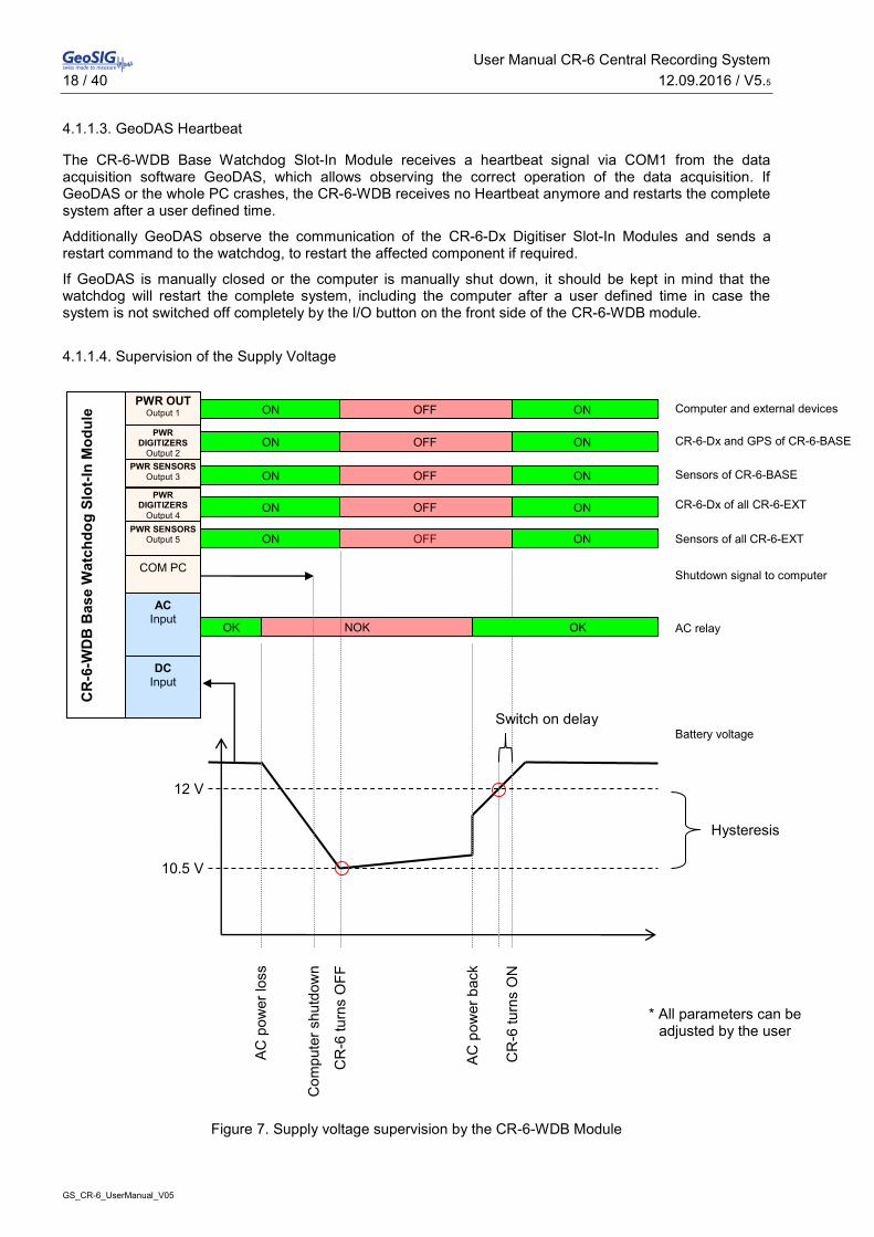
4.1.1.3. GeoDAS Heartbeat
The CR-6-WDB Base Watchdog Slot-In Module receives a heartbeat signal via COM1 from the data acquisition software GeoDAS, which allows observing the correct operation of the data acquisition. If GeoDAS or the whole PC crashes, the CR-6-WDB receives no Heartbeat anymore and restarts the complete system after a user defined time.
Additionally GeoDAS observe the communication of the CR-6-Dx Digitiser Slot-In Modules and sends a restart command to the watchdog, to restart the affected component if required.
If GeoDAS is manually closed or the computer is manually shut down, it should be kept in mind that the watchdog will restart the complete system, including the computer after a user defined time in case the system is not switched off completely by the I/O button on the front side of the CR-6-WDB module.
4.1.1.4. Supervision of the Supply Voltage
Figure 7. Supply voltage supervision by the CR-6-WDB Module
12 V
CR
-6 tu
rns
OFF
COM PC
CR
-6-W
DB
Bas
e W
atch
dog
Slot
-In M
odul
e
PWR DIGITIZERS
Output 4
PWR SENSORS
Output 5
PWR SENSORS Output 3
PWR DIGITIZERS
Output 2
AC Input
PWR OUT Output 1
Computer and external devices
DC Input
Hysteresis
ON OFF ON
CR-6-Dx and GPS of CR-6-BASE ON OFF ON
Sensors of CR-6-BASE
ON OFF ON
ON OFF ON CR-6-Dx of all CR-6-EXT
ON OFF ON Sensors of all CR-6-EXT
10.5 V
CR
-6 tu
rns
ON
AC p
ower
bac
k
Com
pute
r shu
tdow
n
AC p
ower
loss
OK NOK OK
Shutdown signal to computer
Switch on delay
* All parameters can be adjusted by the user
AC relay
Battery voltage

User Manual CR-6 Central Recording System 12.09.2016 / V5.5 19 / 40
GS_CR-6_UserManual_V05
4.1.2. CR-6-Dx Digitiser Slot-In Module
The CR-6-Dx Digitiser Slot-In Module measures the value of the sensor with an ADC. The filtered value will be transferred to the industrial PC to be recorded and analyzed with GeoDAS.
There are two type of CR-6-Dx Digitiser Slot-In Modules:
CR-6-DM: Master Digitiser Slot-In Module – Has an onboard real time clock (RTC) which synchronises itself to the GPS.
CR-6-DS: Slave Digitiser Slot-In Module – Are synchronised to the RTC of the Maser Module
Figure 8 CR-6-Dx Digitiser Slot-In Module
4.1.2.1. LED’s
Function LED Description DATA TRANSFER
ON OFF In case the blue LED is on, the Digitiser Module transfers data to the industrial computer
CH1 STATUS ON OFF Channel 1 is enabled (Green LED on) or disabled (Green LED off)
CH2 STATUS ON OFF Channel 2 is enabled (Green LED on) or disabled (Green LED off)
CH3 STATUS ON OFF Channel 3 is enabled (Green LED on) or disabled (Green LED off)

User Manual CR-6 Central Recording System 20 / 40 12.09.2016 / V5.5
GS_CR-6_UserManual_V05
4.2. Back Side
4.2.1. CR-6-OVPSx Sensor OVP Slot-In Module
Each triaxial sensor is connected to a separate CR-6-OVP-S Sensor OVP Slot-In Module. This Module protects the CR-6 Recording System from over voltage, injected on the sensor cable.
(a)
(b)
Figure 9. CR-6-OVPS1 (a) and CR-6-OVPS2 (b) Sensor OVP Slot-In Module
4.2.1.1. LED
Function LED Description PWR
ON OFF In case the LED is on, the sensor is powered.
User Manual CR-6 Central Recording System 12.09.2016 / V5.5 21 / 40
GS_CR-6_UserManual_V05
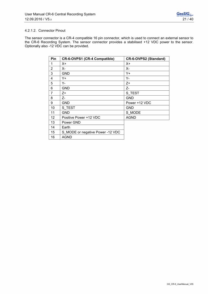
4.2.1.2. Connector Pinout
The sensor connector is a CR-4 compatible 16 pin connector, which is used to connect an external sensor to the CR-6 Recording System. The sensor connector provides a stabilised +12 VDC power to the sensor. Optionally also -12 VDC can be provided.
Pin CR-6-OVPS1 (CR-4 Compatible) CR-6-OVPS2 (Standard) 1 X+ X+ 2 X- X- 3 GND Y+ 4 Y+ Y- 5 Y- Z+ 6 GND Z- 7 Z+ S_TEST 8 Z- GND 9 GND Power +12 VDC 10 S_TEST GND 11 GND S_MODE 12 Positive Power +12 VDC AGND 13 Power GND 14 Earth 15 S_MODE or negative Power -12 VDC 16 AGND

User Manual CR-6 Central Recording System 22 / 40 12.09.2016 / V5.5
GS_CR-6_UserManual_V05
4.2.2. CR-6-OVPx OVP Slot-In Module
The CR-6-OVPB or CR-6-OVPE protects the base or extension rack from over voltage on any incoming cables (e.g. power, Ethernet, phone line, …)
(a)
(b)
Figure 10. CR-6-OVPB (a) and CR-6-OVPE (b) OVP Slot-In Module
4.2.2.1. Connectors
ETHERNET IN
Connection of the CR-6 to the local LAN with a standard RJ45 Ethernet plug.¨
1 TX+ 2 TX- 3 RX+ 4 NC 5 NC 6 RX- 7 NC 8 NC
MODEM IN
In case an internal analog or ISDN modem is installed, the external telephone cable can be connected here with a standard RJ11 plug.
1 NC
2 Phone line A
3 Phone line B
4 NC
1
8
1
4
User Manual CR-6 Central Recording System 12.09.2016 / V5.5 23 / 40
GS_CR-6_UserManual_V05
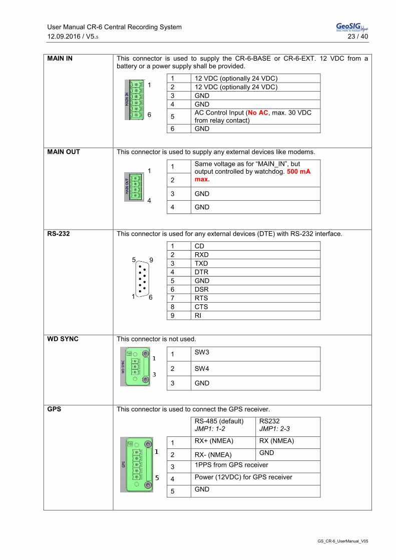
MAIN IN
This connector is used to supply the CR-6-BASE or CR-6-EXT. 12 VDC from a battery or a power supply shall be provided.
1 12 VDC (optionally 24 VDC) 2 12 VDC (optionally 24 VDC) 3 GND 4 GND
5 AC Control Input (No AC, max. 30 VDC from relay contact)
6 GND
MAIN OUT
This connector is used to supply any external devices like modems.
1 Same voltage as for “MAIN_IN”, but output controlled by watchdog. 500 mA max. 2
3 GND
4 GND
RS-232
This connector is used for any external devices (DTE) with RS-232 interface.
1 CD 2 RXD 3 TXD 4 DTR 5 GND 6 DSR 7 RTS 8 CTS 9 RI
WD SYNC
This connector is not used.
1 SW3
2 SW4
3 GND
GPS
This connector is used to connect the GPS receiver.
RS-485 (default) JMP1: 1-2
RS232 JMP1: 2-3
1 RX+ (NMEA) RX (NMEA)
2 RX- (NMEA) GND
3 1PPS from GPS receiver
4 Power (12VDC) for GPS receiver
5 GND
5
1
9
6
1
4
1
6

User Manual CR-6 Central Recording System 24 / 40 12.09.2016 / V5.5
GS_CR-6_UserManual_V05
4.2.3. CR-6-COMx Communication Slot-In-Module
The CR-6-COMB (Base rack) and CR-6-COME (Extension rack) provide the connector interface to the industrial computer or between several racks.
(a)
(b)
Figure 11. CR-6-COMB (a) and CR-6-COME (b) OVP Slot-In Module
4.2.3.1. Connectors
ETHERNET OUT
Connection to PC to the LAN with a standard RJ45 Ethernet plug.
1 TX+ 2 TX- 3 RX+ 4 NC 5 NC 6 RX- 7 NC 8 NC
MODEM OUT
Connection of phone line to the modem with a standard RJ11 plug.
1 NC
2 Phone line A
3 Phone line B
4 NC
1
4
1
8

User Manual CR-6 Central Recording System 12.09.2016 / V5.5 25 / 40
GS_CR-6_UserManual_V05
POWER PC
This connector is used to supply the industrial computer.
1 Same voltage as for “MAIN_IN”, but output controlled by watchdog. (Normally 12 VDC)
2
3 GND 4
SYNC
The sync-connector is used to interconnect a CR-6-BASE with one ore more CR-6-EXT. See chapter 5.2 for details.
1 1PPS
2 SYNC String 3 SW3 4 SW4 5 GND
COM3
Connection of PC to the external devices (DTE) with RS232 interfaces.
1 CD 2 RXD 3 TXD 4 DTR 5 GND 6 DSR 7 RTS 8 CTS 9 RI
COM1, 2, 4, 5, 6, 7
Purpose of connectors:
x COM1 – Connection of the industrial computer to the Watchdog
x COM2 – Connection of the industrial computer to the GPS
x COM4 – Connection of the industrial computer to the CR-6-Dx #1 - 3
x COM5 – Connection of the industrial computer to the CR-6-DS #4 - 6
x COM6 – Connection of the industrial computer to the CR-6-DS #7 - 9
x COM7 – Connection of the industrial computer to the CR-6-DS #10 - 12
1 NC 2 RXD 3 TXD 4 NC 5 GND 6 NC 7 NC 8 NC 9 NC
1
5
6
9
1
5
6
9

User Manual CR-6 Central Recording System 26 / 40 12.09.2016 / V5.5
GS_CR-6_UserManual_V05
5. Installation This section lists the procedures involved in installation, configuration and operation of the instrument. The procedures will be outlined as steps to be performed in the field or in house prior to deploying the instrument in the field.
5.1. Site Selection
5.1.1. Environmental Considerations
The choice of an installation site is similar in most respects to that of a regular continuous recording seismic station.
Although the Instrument is in a solid case, a location shall be arranged that is free from direct sunlight, dangers of falling materials in the event of an earthquake and the risk of tampering or vandalism. Furthermore, the installation site must not be affected by weather conditions such as ice, snow or rain.
The user must ensure that the location is provided with either 115 / 230 VAC or 12 VDC (e.g. from a solar panel or battery).
In case of the setup of the event triggered recordings, any local environmental source of noise, disturbance or vibration around the site must be taken into account. This will cause false triggering of the recording system in case the threshold is set too low. These influencing factors must be taken in account when configuring the trigger settings in GeoDAS.
5.1.2. Power Supply Considerations
The CR-6 is powered by battery and/or an external power supply, connected to 230/115 VAC. The power supply works as a battery charger at the same time and therefore guarantees maximum of autonomy in case of a power loss. A solar panel can be used as well instead of a power supply, ask GeoSIG for more detailed specifications.
x With 115/230 VAC power, a cable has to be connected to the external power supply. The cable must consist of Phase, Neutral and Earth Protection.
x If the system is powered only by battery, the battery must be fully charged at least 24 hours uninterrupted before connecting to the system. The configuration of the instrument may be performed while the charger is connected to the instrument.
a
Please ensure that the right voltage (115 VAC / 60 Hz or 230 VAC / 50 Hz) is selected on the external power supply.
The best solution for the system is to use the battery with the external power supply at the remote installation site. The instrument can be checked and configured locally in the work shop before going on site (e.g. correct time, trigger and all relevant settings). It can be transported then to the installation site (Ensure that the system is “OFF”). When in place and powered again, the system will run with the preconfigured parameters. This will reduce the risk of any complications with regards to the installation site concerning any diverse conditions.
a
Many times the locations of seismic equipment are highly exposed to electrical disturbances caused by lightning or by the industrial environment. It may sometimes be necessary to use additional surge protectors for the equipment. Contact GeoSIG or your local representative for more information.

User Manual CR-6 Central Recording System 12.09.2016 / V5.5 27 / 40
GS_CR-6_UserManual_V05
5.2. Cabling of a CR-6-BASE
In the figure below the external cabling of the CR-6-BASE Base Rack is shown. To interconnect several racks, please see the next chapter.
Figure 12. External cabling of a CR-6-BASE
Sensor
+ _ AC/DC 230/115 VAC
GPS
LAN Phone Line
Sensor
Ethernet RS-232
PCI: 8x RS-232
Power
PCI: Analog Modem

User Manual CR-6 Central Recording System 28 / 40 12.09.2016 / V5.5
GS_CR-6_UserManual_V05
5.3. Interconnection of one or more CR-6-EXT with a CR-6-BASE
In case more than 36 channels are required in one system, the CR-6-BASE Base Rack can be extended by one or several CR-6-EXT Extension Racks, each adding up to 36 additional channels.
Figure 13. Interconnection of a CR-6-EXT with a CR-6-BASE
+ _

User Manual CR-6 Central Recording System 12.09.2016 / V5.5 29 / 40
GS_CR-6_UserManual_V05
6. Configuration and Operation Configuration and data acquisition is done on the supplied computer running GeoDAS. Basic knowledge of Windows XP and GeoDAS is assumed.
a
For the installation and usage of GeoDAS refer to the GeoDAS User Manual, which explains the use of the software in more details.
6.1. Data Storage
The data are stored in the following folders:
Permanent recording C:\GeoDAS_DATA\DataStreams\ADxxx
Event recording C:\GeoDAS_DATA\Data\ADxxx
6.1.1. Data Access on a Remote Computer
In case you have another computer in the same network as the CR-6 system, the following steps can be done to have access to the data over the network.
x Open Windows Explorer on your remote computer
x Click Tools Æ Map Network Drive…
Figure 14. Map a network drive
x Map the drive to the Folder: \\192.168.xx.xx\GeoDAS_DATA. Instead of xx.xx put the IP of the CR-6 industrial computer.
a
If you don’t know how to find out the IP Address, do the following steps on the industrial computer of the CR-6 Recording System: - Click Start Æ Run Æ type cmd, then press OK
- Type ipconfig, then your IP appears Ethernet adapter Local Area Connection: Connection-specific DNS Suffix . : IP Address. . . . . . . . . . . . : 192.168.10.107 Subnet Mask . . . . . . . . . . . : 255.255.255.0 Default Gateway . . . . . . . . . : 192.168.10.254
- Type exit
User Manual CR-6 Central Recording System 30 / 40 12.09.2016 / V5.5
GS_CR-6_UserManual_V05
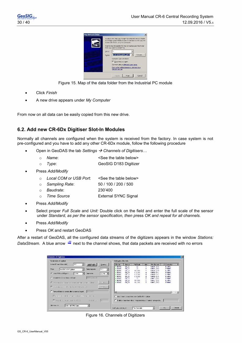
Figure 15. Map of the data folder from the Industrial PC module
x Click Finish
x A new drive appears under My Computer
From now on all data can be easily copied from this new drive.
6.2. Add new CR-6Dx Digitiser Slot-In Modules
Normally all channels are configured when the system is received from the factory. In case system is not pre-configured and you have to add any other CR-6Dx module, follow the following procedure
x Open in GeoDAS the tab Settings Æ Channels of Digitisers…
o Name: <See the table below> o Type: GeoSIG D183 Digitizer
x Press Add/Modify
o Local COM or USB Port: <See the table below> o Sampling Rate: 50 / 100 / 200 / 500 o Baudrate: 230’400 o Time Source External SYNC Signal
x Press Add/Modify
x Select proper Full Scale and Unit: Double click on the field and enter the full scale of the sensor under Standard, as per the sensor specification, then press OK and repeat for all channels.
x Press Add/Modify
x Press OK and restart GeoDAS
After a restart of GeoDAS, all the configured data streams of the digitizers appears in the window Stations: DataStream. A blue arrow next to the channel shows, that data packets are received with no errors
Figure 16. Channels of Digitizers

User Manual CR-6 Central Recording System 12.09.2016 / V5.5 31 / 40
GS_CR-6_UserManual_V05
Name (three letter code) AD1 AD2 AD3 AD4 COM Port COM4 COM5 COM6 COM7
In case more than one rack is connected
Name (three letter code) AD5 AD6 AD7 AD… COM Port COM8 COM9 COM10 COM…
6.2.1. Permanent and Event Recording
All the data are streamed from the digitizer modules to GeoDAS. To configure the permanent and event recording, open in the GeoDAS the tab Settings Æ Data Streams…
The following windows appear:
Figure 17. Setup of permanent and event recoding
If you edit local parameters of the data stream processing then “This Computer” has to be selected as a Configuration target. But there is also a possibility to adjust data stream parameters in the remote instances of GeoDAS if they are configured as remote nodes allowing the remote configuration. See the GeoDAS User Manual for details.

User Manual CR-6 Central Recording System 32 / 40 12.09.2016 / V5.5
GS_CR-6_UserManual_V05
Stream Data Storage (Permanent Recording)
In case the permanent data shall be kept on the system, the flag Keep all active streams of data in local data files must be ticked. In this case the following parameters must be set:
Maximum length of data chunk in each file
Length of one data file. Each data channel creates a separate file. For instance, if a system provides twelve channels and 60 minutes is selected here, then twelve files will be created ever hour. If some data blocks of the stream are lost within this time interval, GeoDAS may create more than one file to keep the data.
Delete oldest data if disk free space is below
Since the data files are recorded permanently, the hard disk of the computer is filled up with data quickly. Therefore care must be taken to avoid hard disk overflow. Minimum amount of a hard disk free space must be set, which is allowed for the normal operation of GeoDAS and the Windows operating system. If the free space reaches this limit, GeoDAS will delete the oldest data stream files in order to continue performing normally.
Remove data files older than Lifetime of permanent data can be specified in hours. Older data will be normally deleted, except if the following option is selected.
Move outdated files to Files are moved to a specified archive directory instead of deleting them.
Event Files
To create separate trigger files in case a threshold is exceeded the flag On any local trigger must be ticked. Then the following parameters must be configured.
Preevent In case the signal is exceeding the trigger threshold, this value defines how many seconds of data will be added at the beginning of the event file before the threshold has been exceeded.
Postevent Defines how long the recording will continue, when the signal was falling below the threshold.
Maximum duration An event file will be closed after this duration, even if the threshold is still exceeded
The trigger threshold must be defined in local trigger settings
Local Trigger Settings
Here for any sensor a trigger can be defined. It can be selected on which axes the trigger should be applied (Channels) and a low- and high pass trigger filter (LPF, HPF) can be defined. Only Level_1 must be filled in the CR-6 Recording System. In case a STA/LTA trigger is required instead of a simple threshold trigger, this can be changed in the drop down menu of Trigger algorithm under Network Triggers and Alarm.
Network Trigger and Alarms
In case an event file should be only created in case several channels are exceeding the trigger threshold, this flag must be ticked. It must then be configured how many channels have to trigger within which time frame to start the recording of all channels. The alarms are not used in CR-6 and shall not be ticked.
For any other settings in this window or details about the triggering algorithms, see the GeoDAS User Manual for details.

User Manual CR-6 Central Recording System 12.09.2016 / V5.5 33 / 40
GS_CR-6_UserManual_V05
6.2.2. Configuration of CR-6-WDB Base Watchdog Slot-In Module
In GeoDAS it must be configured, that the data acquisition program is sending a periodical heart beat to the CR-6-WDB Base Watchdog Slot-In Module. From the factory, this watchdog is already configured and does not have to be changed. If you still want to adjust any parameters, please proceed as described below:
a
Do not delete the configured watchdog. Otherwise the system will restart a couple of times per day.
x Open in the GeoDAS the tab Settings Æ Watchdogs…
x Check the following parameters:
o Name: WD1
o Port: COM1
o Baud rate: 115200
o Press Add Watchdog
o Change all values as seen in Figure 18. For explanations see chapter 6.2.2.1
o Press Apply
o Press Save and Exit
Figure 18: Watchdogs settings of the CR-6
6.2.2.1. Detail Explanation of the Watchdog Parameters
GeoDAS Activity
Watchdog monitors GeoDAS activity The WD module supervises the heartbeat sent by GeoDAS and will reset the system in case the heartbeat stops
Watchdog timout counter is reset by a critical GeoDAS routine
Not needed in CR-6, do not tick this flag!
Shut the computer down on low voltage level In case of low voltage, GeoDAS is initiating a proper Windows shut down before the WD module is switching off the power
User Manual CR-6 Central Recording System 34 / 40 12.09.2016 / V5.5
GS_CR-6_UserManual_V05
Statistics
Counters are showing how many times the WD module has reset the system because of problems with receiving the heartbeat or low supply voltage level. And how many times the system has been started up or AC has been lost.
Power Control
Main Output Supply voltage of the computer and other optional external devices
Power Output 1 Supply voltage of the CR-6-Dx Digitiser Modules in the CR-6-BASE Base Rack and the GPS
Power Output 2 Supply voltage of all the sensors connected to the CR-6-BASE Base Rack
Power Output 3 Supply voltage of the CR-6-Dx Digitiser Modules in all the CR-6-EXT Extension Racks
Power Output 4 Supply voltage of all the sensors connected to the CR-6-EXT Extension Racks
Time Parameters
Low supply voltage – System shutdown Defines how long the supply voltage must be below the set “Low” threshold till the system is switched off.
Supply voltage recovery – System startup Defines how long the system remains off, after the supply voltage has been recovered above the set “Good” threshold.
No supervised communication – Error declaration Defines how long a heartbeat must be pending till an error is declared.
No supervised communication – First system reset Defines how long a communication error must apply, before the system will restart the first time.
No supervised communication – Next system resets In case the heartbeat is not coming back after the first restart, this parameter defines how long a communication error must apply, before the system will restart again and again.
System power off during resets Defines how long the power is off during the reset of the system
System startup – start of the communication supervision
The CR-6-WDB is not supervising the heartbeat or the voltages during this time to allow the system to be started up properly.
Monitoring of Voltages
Threshold Low If the supply voltage is below this value, the system will switch off after the user defined delay.
Threshold Good If after a power loss the supply voltage recovers again above this value, the system will switch on after the user defined delay.
Actual supply voltage Value of the actual supply voltage Actual AC power status Status of AC supply, measured by external relay
contact.
Monitoring of Communication and Miscellaneous
These parameters are not needed in CR-6 and shall not be enabled!

User Manual CR-6 Central Recording System 12.09.2016 / V5.5 35 / 40
GS_CR-6_UserManual_V05
6.3. Data Streaming to Remote Computer
6.3.1. Settings on the Industrial Computer of the CR-6
The following settings must be done on the Industrial PC module after login over Remote Desktop:
x Open GeoDAS
x Click Settings Æ Network Links…
x Put in the following data on the left side of the window (see Figure 19)
o Enable network links with the remote applications: Enabled
o Network name: CR-6
o IP Address: Default
o Accept request from the remote clients at port: Enabled, 1024
o Support functions of a remote node: Enabled: - Real time data streaming - Remote configuration
x Click OK
x Restart GeoDAS
Figure 19. Data forwarding over Network

User Manual CR-6 Central Recording System 36 / 40 12.09.2016 / V5.5
GS_CR-6_UserManual_V05
6.3.2. Remote Computer Settings
The following settings must be done on the computer, where you want to receive the data streams:
x Open GeoDAS
x Click Settings Æ Network Links…
x Put in the following data (see Figure 20)
o Enable network links with the remote applications: Enabled
o Local settings of this application, Network name: Workstation
o Local settings of this application, IP Address: Default
o Remote application, Network name: CR-6
o Remote application, IP Address: <IP Address of the CR-6>
o Remote application, Connect through the port: 1024
o Remote application, Connection timeout, sec: 40
o Remote application, Inactivity timeout, sec: 600
o Remote application, Remote node Enabled: - Real time data streaming - Remote configuration
o Permanent monitoring: Enabled
x Click Add, then OK
x Restart GeoDAS
Figure 20. Network Links
x In the window Remote Nodes and Applications a new station CR-6 appears.

User Manual CR-6 Central Recording System 12.09.2016 / V5.5 37 / 40
GS_CR-6_UserManual_V05
x In the window Stations: Data Streams the network CR-6 will all channels appears
Figure 21 Remote streams
x For display of the streams make a right-click on the cannel and press Data Monitor
For more details see GeoDAS User Manual

User Manual CR-6 Central Recording System 38 / 40 12.09.2016 / V5.5
GS_CR-6_UserManual_V05
7. Functional Description This section discusses some technical details how the Instrument works. Input signal filtering, digitising, and time accounting are among the functions described.
7.1. Signal Conditioning
Electrical signals from seismic sensors connected to the Instrument are range-adjusted in preparation for conversion to digital form and are filtered to prevent aliasing effects. The signals are next sampled and digitised, and then digitally filtered under software control to further reduce noise. Then these data are used for triggering and recording within the GeoDAS software package.
Depending on the jumper configuration, the instrument accepts signals from sensors within the sensor voltage output ranges as follows:
Jumpers on CR-6-Dx Digitiser Slot-In Modules Range JMPX1
JMPY1 JMPZ1
JMPX2 JMPY2 JMPZ2
JMPX3 JMPY3 JMPZ3
0 ± 10 VDC (20 Vpp) Differential open 1-2 1-2 0 ± 2.5 VDC (5 Vpp) Differential open open open 0 ± 10 VDC (20 Vpp) Single Ended 1-2 1-2 1-2 0 ± 2.5 VDC (5 Vpp) Single Ended 1-2 open open 2.5 VDC ± 2.5 VDC Single Ended 2-3 open open
Examples:
Depending on the jumper settings, the input signals will all be internally unified to a single range 0 to 5 V. The Digital Values (DV) for Analog Input Voltages (AIV) are summarised in the following table:
Analog Input Voltage AIV [V]
Digital Value DV [Bit]
Minimum input 0.0 -(223 – 1) x 90% = -7549746 Zero input 2.5 0 Maximum input 5.0 223 x 90% = 7549746
Each channel of the CR-6 has a low-pass 250 Hz 4th-order Butterworth analog filter prior to being sampled and converted to digital form. This filter removes signal energy at frequencies above one-half the input sampling rate (1000 Hz), so that higher frequencies are not aliased by the sampling process. For different
Default Input Range: 0 ± 10 VDC (20 Vpp) differential 2.5 ± 2.5 VDC single ended

User Manual CR-6 Central Recording System 12.09.2016 / V5.5 39 / 40
GS_CR-6_UserManual_V05
sampling rates, further anti-aliasing is achieved by digital filters in the DSP (equi-ripple FIR filter structures with the linear phase) with a -3dB point above 80% of the Nyquist rate. Any delay from the digital filter is directly compensated inside the DSP.
a
The sampling rate is common to all three channels digitised by one CR-6-Dx Digitiser Slot-In Module, i.e. the sampling rate cannot be individually set for a specific channel.
7.2. Triggering
The CR-6-Dx Digitiser Slot-In Modules do not have any data storage capability. They acts as a digitiser by simply forwarding the data to the remote host. The recording itself is performed by the GeoDAS software package on the industrial computer. For more information about the possibility of triggering or to record the data, please see chapter 6.2.1 consult the GeoDAS User Manual.
7.3. Clock
The Instrument has a complete, self-contained time-keeping system (RTC). This clock keeps track of days, hours, minutes and seconds. The instrument synchronise the clock automatically with an encoded external time signal coming from a GPS. The clock operates from the internal battery and runs regardless whether the main switch is at ON or OFF position. If the CR-6 Recording System is stored in shelf please see chapter 2.3.2) to avoid that the backup battery for the RTC is discharged.
7.3.1. GPS Option
The GPS (Global Positioning System) is originally used for navigation. It contains several satellites, which orbit the earth in a distance of about 20 000 km. The signals transmitted by the satellites are used to get the position; minimum 4 satellites have to be received by the GPS receiver to find its exact position. The transmitted signals contain also precise time information, which is used to update the internal clock of the Instrument.
7.3.2. Synchronisation
The RTC of the CR-6-DM Master Digitiser Slot-In Module synchronise its clock to the GPS. All other CR-6-DS Slave Digitiser Slot-In Modules synchronise their time to the CR-6-DM Master Digitiser. This setup guarantees, that all channels remain synchronised, even if the GPS is failing or having no signal.

User Manual CR-6 Central Recording System 40 / 40 12.09.2016 / V5.5
GS_CR-6_UserManual_V05
8. Maintenance The Instrument has been designed in a way that it requires a minimum of maintenance. If the following procedures are performed frequently, the instrument will last for many years:
x The periodic test indicates any irregularity as soon as it occurs. Therefore it is recommended, to check the recorded sensor test at least once a year. Compare the signals of the 3 channels with older records. There should not be a distinctive change.
x The function of a sensor with DC response (capacitive, piezo-resistive and FBA sensors) can be checked by inclining the sensor in every axis. An inclination of 90° causes an acceleration of 1.0 g, 30° an acceleration of 0.5 g and 14.7° an acceleration of 0.25 g. Check this value for every channel. This check should be performed annually.
x The function of the sensor can be checked frequently with a tilt table. For testing the sensor has to be installed onto the tilt table. The whole range of ± 1g has to be checked with the table. Every axis shall be performed. The output signal has to be compared with the calibration values given by the manufacturer. A sensor without AC response needs to be checked by using a shaking table. The period of this check depends on the used sensor type. For detailed information refer to the data sheet of your sensor.
x The voltage of the optional battery and the charging voltage of the charger shall be measured annually. Disconnect the AC power to measure the battery voltage, keep the Instrument switched on. The voltage should be between 11.8 and 13.2 VDC, depending on its charge. Reconnect the AC power cable, switch off the Instrument and disconnect the battery, measure the voltage on the battery cables. The voltage should be 13.8 ± 0.3 VDC.
x The physical condition of the Instrument and the sensor should be checked annually. Make sure every cable and connector is in good condition and plugged in properly.
x The optional battery should be replaced every 3 years. After replacement, adjust the date of installation and the date of the next replacement into the Instrument via GeoDAS.
x The backup battery on the CR-6DM Master Digitiser Slot-In Module should be replaced every 5 years.