Embed Size (px)
Citation preview
User Manual ControlPlex® CPC20EN Controller
2
1 Table of contents
1 Table of contents 2
2 General information 4
2.1 Safety instructions 4
2.2 Qualified personnel 4
2.3 Use 4
2.4 Delivery state 4
3 General description 5
3.1 Design of the entire system 6
3.2 Dimensions CPC20 7
3.3 Dimensions 18plus-EM03 supply module 7
3.4 Dimensions 18plus- AM03 connection module 7
3.5 Dimensions 18plus-TM03 transfer module 7
3.6 Dimensions of 18plus-AM03 connection module with ESX60D 8
3.7 Status indication and terminals 8
3.7.1 Terminals for voltage supply 9
3.7.2 Connector for the additional ELBus® 9
3.7.3 USB service and maintenance interface, terminal X3 9
3.7.4 EtherNet/IP™ interfaces with integral switch,
connection sleeve XF1, XF2 10
3.7.5 ETHERNET interface, connection sleeve X1 10
3.7.6 LED status indication 10
4 Mounting and installation 11
4.1 Mounting of the system 11
4.2 System installation 12
5 Operating modes of the CPC20 bus controller 13
5.1 Operating mode: Start-up mode 13
5.2 Operating mode: System error mode 13
5.3 Operating mode: Configuration error mode 13
5.4 Operating mode: stand-alone mode 13
5.5 Operating mode: Slave mode 13
5.6 Operating mode: Firmware Update Mode 13
6 Basic functionalities of the entire system 14
6.1 Internal cycle times 14
6.2 Hot swap of circuit protectors 14
6.3 Communication via the USB service interface 14
6.4 About the additional Ethernet interface 14
6.4.1 Web Server 14
6.4.1.1 Default IP address -X91 14
6.4.1.2 User name and password 14
3
7 Communication via EtherNet/IP™ 15
7.1 ControlPlex® device model 15
7.2 EDS file 16
7.3 Identity Object (Class ID: 0x01) 16
7.4 TCP/IP Interface Object (Class ID: 0xF5) 17
8 Cyclical I/O data 18
8.1 I/O data input: CPC20 controller 18
8.2 I/O data input: total current 18
8.3 I/O data input: circuit protectors 19
8.4 Output data circuit protectors: 20
9 Non-cyclical data 22
9.1 CPC20 controller 23
9.1.1 »Device information« CPC20 Controller 23
9.1.2 »Configuration« configuration data of CPC20 Controller 24
9.1.3 »System commands« system commands CPC20 Controller 25
9.1.4 »Dynamic information« Dynamic information CPC20 Controller 25
9.2 Circuit protectors/channels 26
9.2.1 »Parameter channel« device parameters for a channel 26
9.2.2 »Device information« device information for one channel 27
9.2.3 »Device type config« configuration data of for one channel 27
9.2.4 »Event« event message for one channel 28
9.2.5 »Action commands« action commands for one channel 28
9.2.6 »Dynamic Info« dynamic information for one channel 29
9.2.7 »History« bar chart of circuit protector 31
10 Appendix 22
10.1 List of pictures 23
10.2 Technical data 23
4
2 General information
2.1 Safety instructionsThis manual points out possible danger for
your personal safety and gives instruction
how to avoid property damage. The
following safety symbols are used to
draw the reader's attention to the safety
instructions included in this manual.
Danger!Danger to life and limb unless the following
safety precautions are taken.
WarningDanger to machinery, materials or the
environment unless the following safety
precautions are taken.
NoteInformation is provided to allow a better
understanding.
CautionElectrostatically sensitive devices (ESD).
Devices must exclusively be opened by
the manufacturer.
Disposal guidelinesPackaging can be recycled and should
generally be brought to re-use.
2.2 Qualified personnelThis user manual must exclusively be used
by qualified personnel, who are able –
based on their training and experience – to
realise arising problems when handling the
product and to avoid related hazards. These
persons have to ensure that the use of the
product described here meets the safety
requirements as well as the requirements
of the presently valid directives, standards
and laws.
2.3 UseThe product is part of a continuous
enhancement process. Therefore there
might be deviations between the product
in hand and this documentation. These
deviations will be remedied by a regular
review and resulting corrections in future
editions. The right to make changes
without notice is reserved. Error and
omissions excepted.
2.4 Delivery stateThe product is supplied with a defined
hardware and software configuration.
Any changes in excess of the documented
options are not permitted and lead to
liability exclusion.
5
3 General description
Requirements regarding transparency
and flexibility are constantly growing in
industrial applications. Modern automation
technology meets these requirements
with cross-linked components and their
communication capabilities in a range of
business levels and sectors. Control and
computer-aided solutions are no longer
the sole focus, but monitoring of individual
components and processes becomes
more and more important. This is exactly
the target application area of the intelligent
and bus-capable power distribution
system ControlPlex®. It serves for the
protection of industrial applications as
well for monitoring and control. The
CPC20 bus controller is the centre piece
of the system. It analyses measuring
data, indicates error and transmits the
information to the superordinate control
systems by means of standard bus
systems. Its OPC* UA interface offers the
option of direct communication with a
company’s IT infrastructure.
The CPC20 has been designed as a
system in connection with module
18plus. It consists of a supply module for
supply of max. 80 A. Up to 16 connection
modules can be connected, each of them
accommodating one double-channel
electronic circuit protector. In the end
the user has max. 32 channels for his
protection system. When using a transfer
module, the number of channels can even
be doubled once more. Thus the CPC20
offers a maximum number of 64 channels.
Communication options comprise
transmission of the operating condition, of
measuring values and device information
regarding the connected components,
but also changes of the product-specific
parameters such as current ratings and
execution of actions, e.g. ON and OFF
operation.
Information can be transmitted in a cyclical
or non-cyclical mode to the superordinate
control system, the Ethernet interface
or via an available service interface to
the connected service computer. If no
connection is available to a superordinate
control unit, this will have no effect on
the behaviour of the connected circuit
protectors. The bus controller is able to
ensure their functionality even without a
connection to a superordinate control unit.
The saved parameters will be used for this
purpose.
The ControlPlex® intelligent power
distribution system offers the well-known
E-T-A quality and reliability with regard to
overcurrent protection in combination with
the innovative functionalities on the score
of automation technology.
* under preparation. Can be retrofitted via firmware update when available.
6
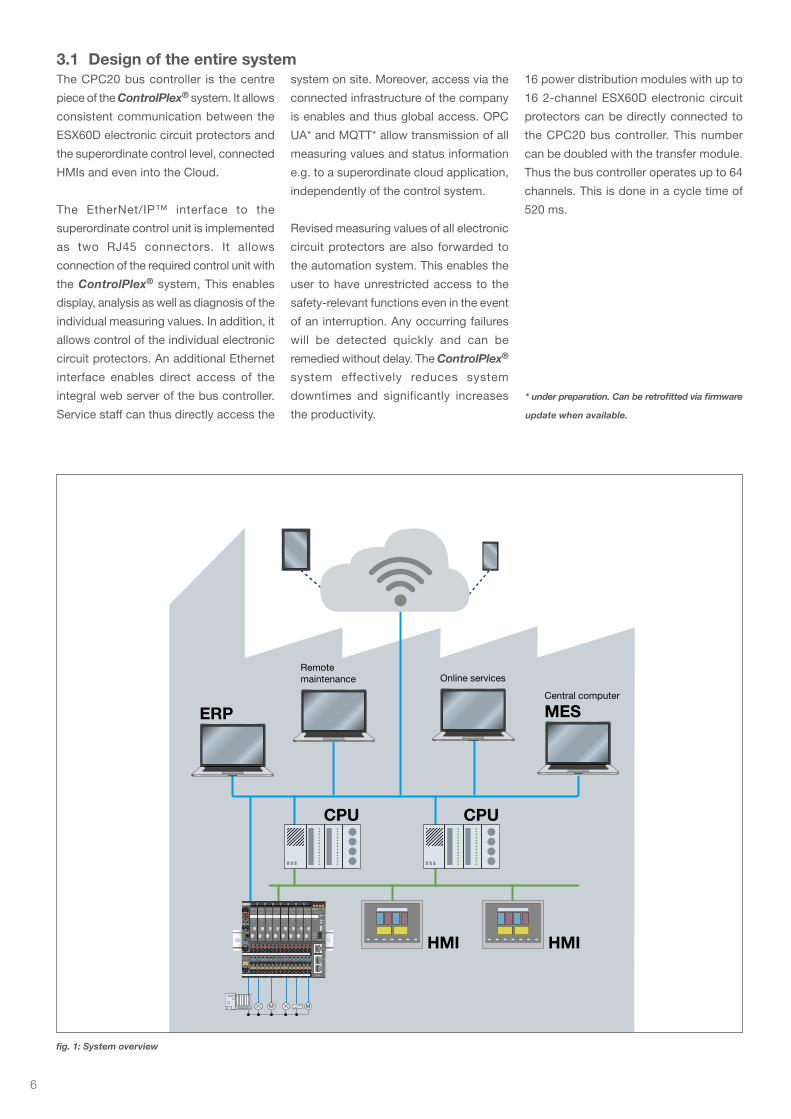
3.1 Design of the entire systemThe CPC20 bus controller is the centre
piece of the ControlPlex® system. It allows
consistent communication between the
ESX60D electronic circuit protectors and
the superordinate control level, connected
HMIs and even into the Cloud.
The EtherNet/IP™ interface to the
superordinate control unit is implemented
as two RJ45 connectors. It allows
connection of the required control unit with
the ControlPlex® system, This enables
display, analysis as well as diagnosis of the
individual measuring values. In addition, it
allows control of the individual electronic
circuit protectors. An additional Ethernet
interface enables direct access of the
integral web server of the bus controller.
Service staff can thus directly access the
system on site. Moreover, access via the
connected infrastructure of the company
is enables and thus global access. OPC
UA* and MQTT* allow transmission of all
measuring values and status information
e.g. to a superordinate cloud application,
independently of the control system.
Revised measuring values of all electronic
circuit protectors are also forwarded to
the automation system. This enables the
user to have unrestricted access to the
safety-relevant functions even in the event
of an interruption. Any occurring failures
will be detected quickly and can be
remedied without delay. The ControlPlex®
system effectively reduces system
downtimes and significantly increases
the productivity.
16 power distribution modules with up to
16 2-channel ESX60D electronic circuit
protectors can be directly connected to
the CPC20 bus controller. This number
can be doubled with the transfer module.
Thus the bus controller operates up to 64
channels. This is done in a cycle time of
520 ms.
* under preparation. Can be retrofitted via firmware
update when available.
fig. 1: System overview
MM
CPUCPU
HMIHMI
ERP MESCentral computer
Online servicesRemote maintenance
7
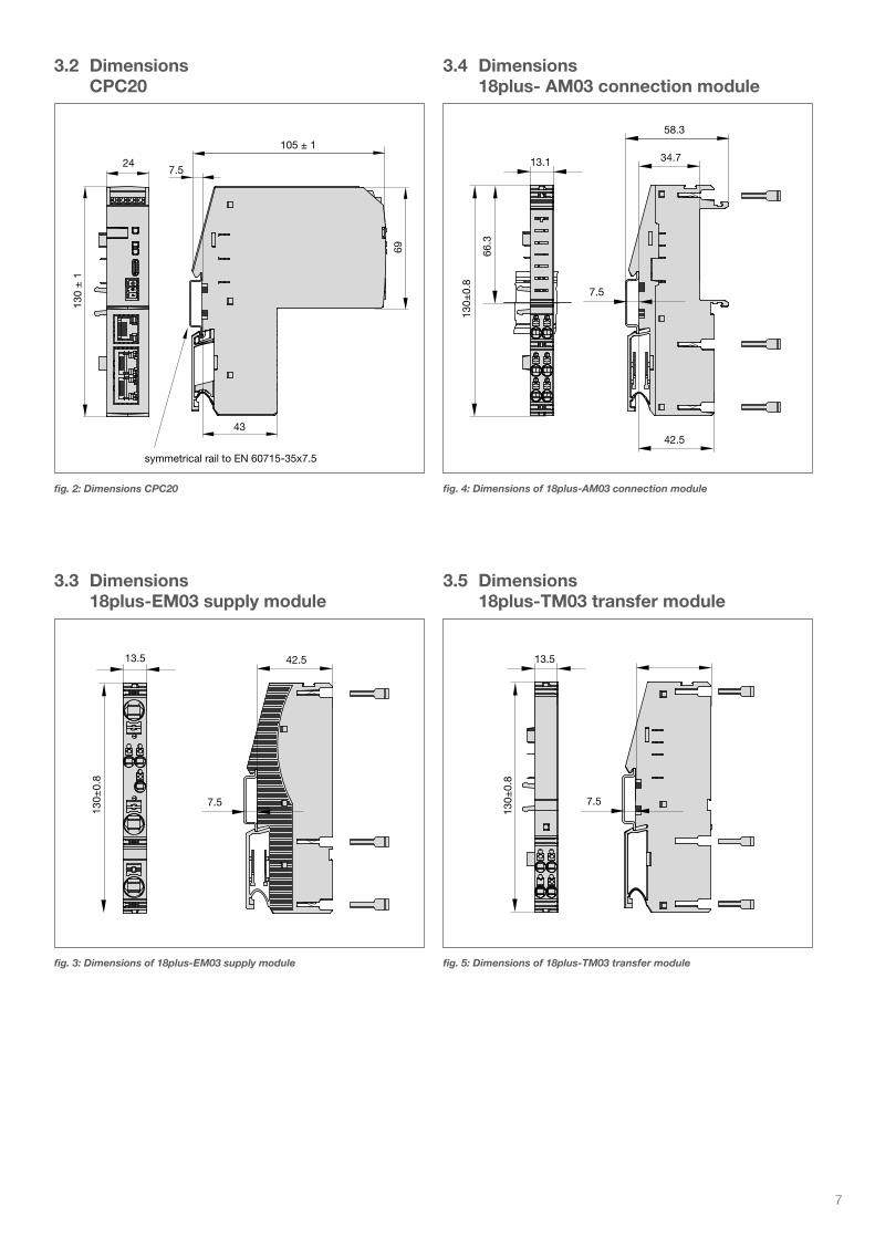
3.2 Dimensions CPC20
3.3 Dimensions 18plus-EM03 supply module
3.4 Dimensions 18plus- AM03 connection module
3.5 Dimensions 18plus-TM03 transfer module
fig. 2: Dimensions CPC20 fig. 4: Dimensions of 18plus-AM03 connection module
fig. 5: Dimensions of 18plus-TM03 transfer modulefig. 3: Dimensions of 18plus-EM03 supply module
7.5
105 ± 1
43
symmetrical rail to EN 60715-35x7.5
24
69
130
± 1
130±
0.8
42.513.5
7.5
130±
0.8
66.3
34.7
58.3
42.5
13.1
7.5
130±
0.8
13.5
7.5
8
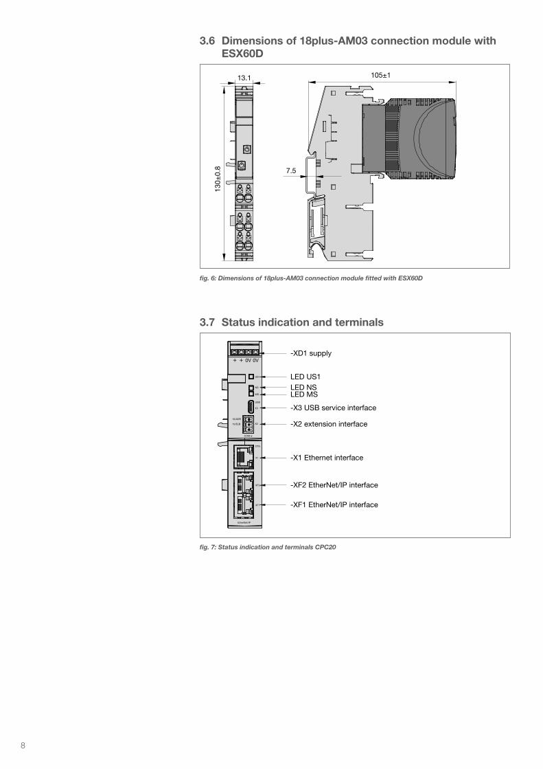
3.6 Dimensions of 18plus-AM03 connection module with ESX60D
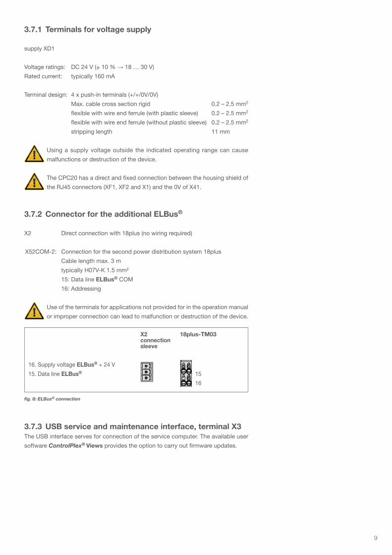
3.7 Status indication and terminals
130±
0.8
105±113.1
7.5
-XD1 supply
LED US1LED NSLED MS
-X3 USB service interface
-X2 extension interface
-X1 Ethernet interface
-XF2 EtherNet/IP interface
-XF1 EtherNet/IP interface
Type CPC20EN
US1
NS
MS
USB
X3
X2
COM-2
ETH
X1
XF2
XF1
EtherNet/IP
16/ADR
15/ELB
+ + 0V 0V
fig. 6: Dimensions of 18plus-AM03 connection module fitted with ESX60D
fig. 7: Status indication and terminals CPC20
9
3.7.1 Terminals for voltage supply
supply XD1
Voltage ratings: DC 24 V (± 10 % → 18 … 30 V)
Rated current: typically 160 mA
Terminal design: 4 x push-in terminals (+/+/0V/0V)
Max. cable cross section rigid 0.2 – 2.5 mm2
flexible with wire end ferrule (with plastic sleeve) 0.2 – 2.5 mm2
flexible with wire end ferrule (without plastic sleeve) 0.2 – 2.5 mm2
stripping length 11 mm
Using a supply voltage outside the indicated operating range can cause
malfunctions or destruction of the device.
The CPC20 has a direct and fixed connection between the housing shield of
the RJ45 connectors (XF1, XF2 and X1) and the 0V of X41.
3.7.2 Connector for the additional ELBus®
X2 Direct connection with 18plus (no wiring required)
X52COM-2: Connection for the second power distribution system 18plus
Cable length max. 3 m
typically H07V-K 1.5 mm²
15: Data line ELBus® COM
16: Addressing
Use of the terminals for applications not provided for in the operation manual
or improper connection can lead to malfunction or destruction of the device.
3.7.3 USB service and maintenance interface, terminal X3The USB interface serves for connection of the service computer. The available user
software ControlPlex® Views provides the option to carry out firmware updates.
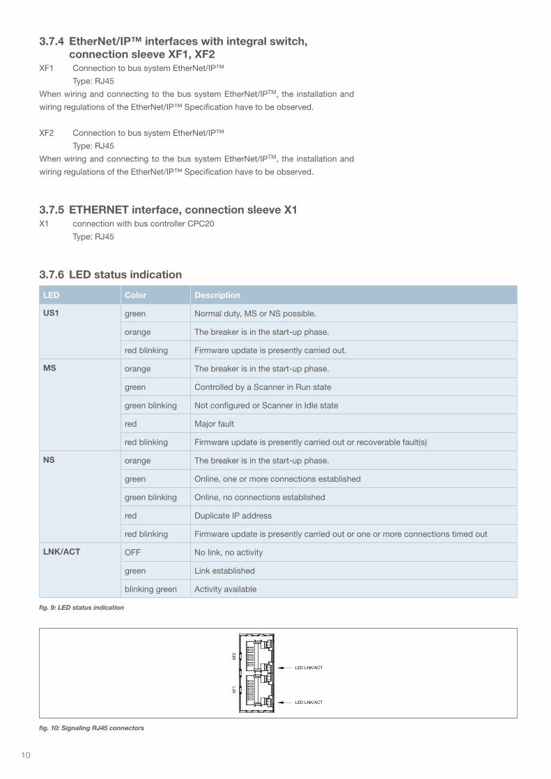
X2 18plus-TM03 connection sleeve
16. Supply voltage ELBus® + 24 V
15. Data line ELBus® 15
16
130±
0,8
42,513,5
7,5
fig. 8: ELBus® connection
10
3.7.4 EtherNet/IP™ interfaces with integral switch, connection sleeve XF1, XF2
XF1 Connection to bus system EtherNet/IP™
Type: RJ45
When wiring and connecting to the bus system EtherNet/IPTM, the installation and
wiring regulations of the EtherNet/IP™ Specification have to be observed.
XF2 Connection to bus system EtherNet/IP™
Type: RJ45
When wiring and connecting to the bus system EtherNet/IPTM, the installation and
wiring regulations of the EtherNet/IP™ Specification have to be observed.
LED Color Description
US1 green Normal duty, MS or NS possible.
orange The breaker is in the start-up phase.
red blinking Firmware update is presently carried out.
MS orange The breaker is in the start-up phase.
green Controlled by a Scanner in Run state
green blinking Not configured or Scanner in Idle state
red Major fault
red blinking Firmware update is presently carried out or recoverable fault(s)
NS orange The breaker is in the start-up phase.
green Online, one or more connections established
green blinking Online, no connections established
red Duplicate IP address
red blinking Firmware update is presently carried out or one or more connections timed out
LNK/ACT OFF No link, no activity
green Link established
blinking green Activity available
XF2
LED LNK/ACT
LED LNK/ACT
XF1
3.7.5 ETHERNET interface, connection sleeve X1X1 connection with bus controller CPC20
Type: RJ45
3.7.6 LED status indication
fig. 9: LED status indication
fig. 10: Signaling RJ45 connectors
11
4 Mounting and installation
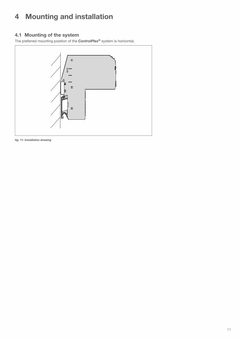
4.1 Mounting of the systemThe preferred mounting position of the ControlPlex® system is horizontal.
fig. 11: Installation drawing
12
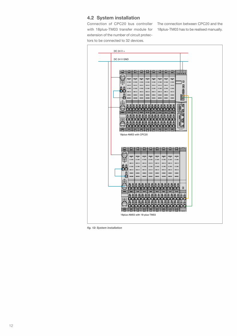
4.2 System installationConnection of CPC20 bus controller
with 18plus-TM03 transfer module for
extension of the number of circuit protec-
tors to be connected to 32 devices.
The connection between CPC20 and the
18plus-TM03 has to be realised manually.
PROFINET
DC 24 V +
18plus-AM03 with CPC20
18plus-AM03 with 18-plus-TM03
DC 24 V GND
fig. 12: System installation
13
5 Operating modes of the CPC20 bus controller
5.1 Operating mode: Start-up modeThe CPC20 bus controller is initialized by applying the supply
voltage. The device will carry out implemented program memory
tests and self test routines. During this time a communication
via the interfaces is not possible.
5.2 Operating mode: System error modeIf a failure is detected during the self test routines, the bus
controller will change into operating mode System Error. This
operating mode can only be discontinued by way of re-starting
the device and it prevents the data exchange via the interfaces.
If the bus controller is in this operating mode, it is unable to
control the electronic circuit protectors and these will stay in the
stand-alone mode (overcurrent protection).
5.3 Operating mode: Configuration error mode
If there are no valid or invalid configuration data available in
the bus controller, it will change into this operating mode. This
operating mode only allows non-cyclical data exchange. Cyclical
data exchange is prevented. Leave this operating mode upon
receipt of the correct slot parameters and configuration data.
5.4 Operating mode: stand-alone modeIn normal duty there is a connection between the bus controller
and the superordinate control unit. Thus the control of the
electronic circuit protectors and the change of their parameters
is executed by the superordinate control unit. Should the
communication between both participants fail, this has no
influence on the protective function of the circuit protectors. In
this case the CPC20 bus controller will automatically adopt the
control and parameterisation of the electronic circuit protectors,
because all required data sets are saved within the CPC20. By
means of the web server, the electronic circuit protectors, their
status and parameters can be accessed via the Ethernet interface
interface. It is thus possible to change e.g. parameter data of
the various electronic circuit protectors. If the failure on the
communication level is remedied, this operating mode will be left
and the superordinate control unit will take over control again as
master. If during this time a parameter was changed while there
was no communication, this will be signaled to the superordinate
control unit. In this case the user can correspondingly define the
control behaviour and it can be programmed in the programmable
logic controller. This allows the user to select a reaction meeting
his requirements.
5.5 Operating mode: Slave modeIn this operating mode the CPC20 is connected to a
EtherNet/IPTM system. Communication to the CPC20 bus
controller works faultlessly and the controller can be addressed
and controlled by the superordinate control unit.
The behaviour of the bus controller with simultaneous use of
a field bus interface and of the web server or the USB service
and maintenance interface can be determined by means of the
configuration of the device in the superordinate control unit. It can
be pre-selected there that Ethernet and/or the USB service and
maintenance interface are granted either only reader access or
reader and editor access. In the event of editor access, changes
of the parameterisation of the electronic circuit protectors can be
carried out in parallel to the field bus system. These parameter
changes will then be advised to the superordinate control system
and can be adopted by it or also overwritten. The user can select
the behaviour accordingly.
5.6 Operating mode: Firmware Update Mode
The devices are supplied with a software programmed according
to their functionality. If the functions of the devices are extended,
this will be carried out in the firmware. It is therefore necessary to
carry out a firmware update if the new functionality shall be used.
14
6 Basic functionalities of the entire system
6.1 Internal cycle timesThe cycle time of the system depends on the number of data
to be transmitted between the CPC20 bus controller and the
projected slots for the ESX60D electronic circuit protectors.
It is possible to choose the data quantity for the communication
of the superordinate control unit. This can be achieved by using
the different data models. It is therefore possible to transmit
either the status, the measuring values for the load current and
the output voltage of the electronic circuit protector or to only
send the circuit protector status to the superordinate control unit.
The choice between the various data models is made available
to the user in the GSDML file of the control system. These are
configuration data which are transmitted to the programmable
logic controller by means of the hardware configuration of the
CPC20.
The cycle time per bus with 16 18plus-AM03 modules is approx.
520 ms for the cyclical data. A window of 70 ms is kept free for
non-cyclical data. In total, this is a max. cycle time of 590 ms.
The ESX60D electronic circuit protectors can be plugged
into the 18plus-AM03 power distribution module at any time.
After plugging in a circuit protector, it will automatically be
parameterised if parameters are available for the slot in question.
6.2 Hot swap of circuit protectorsTransmission of the parameters will be without interruption of
the cyclical data exchange between the CPC20 and the ESX60D
electronic circuit protector.
6.3 Communication via the USB service interface
The maintenance and service interface allows direct access to
the CPC20 bus controller. Firmware updates for the CPC20 are
possible via this interface.
6.4 About the additional Ethernet interface
The additional Ethernet interface extends the functional scope
of the bus controller. The following functionalities are provided
via this interface.
6.4.1 Web ServerThe web server offers the entire scope of measuring data, status
information, parameterisation options an d control function of
the CPC20 bus controller. The parameterisation of the interface
is described separately.
6.4.1.1 Default IP address -X91The default IP address of the CPC20 is: 192.168.1.1
The web server can be reached via this IP address.
6.4.1.2 User name and passwordIn order to be able to carry out configurations, the user has
to have the required access authorisation. It is defined in user
administration.
The default settings are:
We urgently recommend to individually adjust these
settings upon startup of the device.
User admin
Password: admin
15
7 Communication via EtherNet/IP™
EtherNet/IP™ is a network adaption of the Common Industrial
Protocol (CIP™) developed by the ODVA organization. CIP uses
abstract object modeling to describe the available communica-
tion services and data provided by a product. Objects and their
components are addressed by an addressing scheme consisting
of Node Address (IP-Address), Class Identifier (Class ID), Instan-
ce Identifier (Instance ID), Attribute Identifier (Attribute ID) and a
Service Code. Assembly objects are used for I/O messages by
combining several I/O data into one block.
The IP-Address is typically assigned by a DHCP-server within
the network.
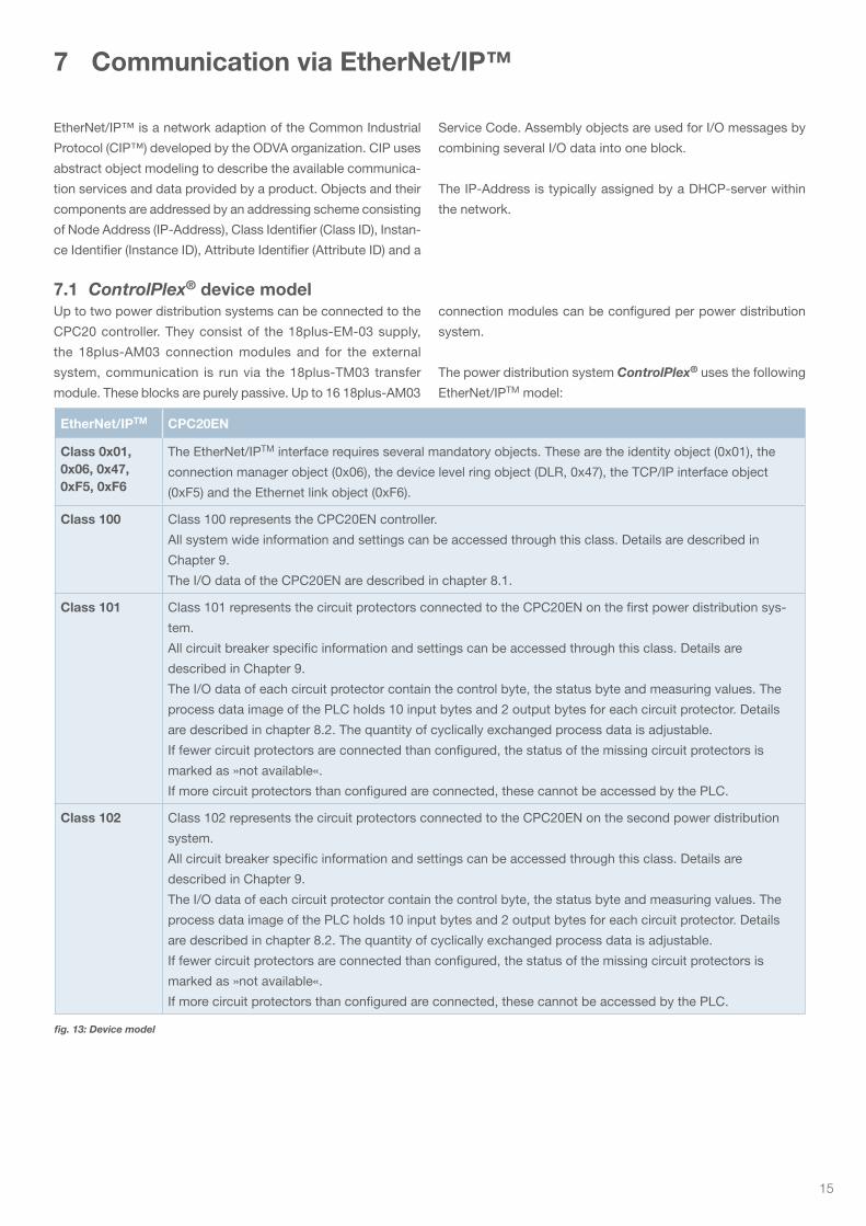
7.1 ControlPlex® device modelUp to two power distribution systems can be connected to the
CPC20 controller. They consist of the 18plus-EM-03 supply,
the 18plus-AM03 connection modules and for the external
system, communication is run via the 18plus-TM03 transfer
module. These blocks are purely passive. Up to 16 18plus-AM03
connection modules can be configured per power distribution
system.
The power distribution system ControlPlex® uses the following
EtherNet/IPTM model:
EtherNet/IPTM CPC20EN
Class 0x01, 0x06, 0x47, 0xF5, 0xF6
The EtherNet/IPTM interface requires several mandatory objects. These are the identity object (0x01), the
connection manager object (0x06), the device level ring object (DLR, 0x47), the TCP/IP interface object
(0xF5) and the Ethernet link object (0xF6).
Class 100 Class 100 represents the CPC20EN controller.
All system wide information and settings can be accessed through this class. Details are described in
Chapter 9.
The I/O data of the CPC20EN are described in chapter 8.1.
Class 101 Class 101 represents the circuit protectors connected to the CPC20EN on the first power distribution sys-
tem.
All circuit breaker specific information and settings can be accessed through this class. Details are
described in Chapter 9.
The I/O data of each circuit protector contain the control byte, the status byte and measuring values. The
process data image of the PLC holds 10 input bytes and 2 output bytes for each circuit protector. Details
are described in chapter 8.2. The quantity of cyclically exchanged process data is adjustable.
If fewer circuit protectors are connected than configured, the status of the missing circuit protectors is
marked as »not available«.
If more circuit protectors than configured are connected, these cannot be accessed by the PLC.
Class 102 Class 102 represents the circuit protectors connected to the CPC20EN on the second power distribution
system.
All circuit breaker specific information and settings can be accessed through this class. Details are
described in Chapter 9.
The I/O data of each circuit protector contain the control byte, the status byte and measuring values. The
process data image of the PLC holds 10 input bytes and 2 output bytes for each circuit protector. Details
are described in chapter 8.2. The quantity of cyclically exchanged process data is adjustable.
If fewer circuit protectors are connected than configured, the status of the missing circuit protectors is
marked as »not available«.
If more circuit protectors than configured are connected, these cannot be accessed by the PLC.
fig. 13: Device model
16
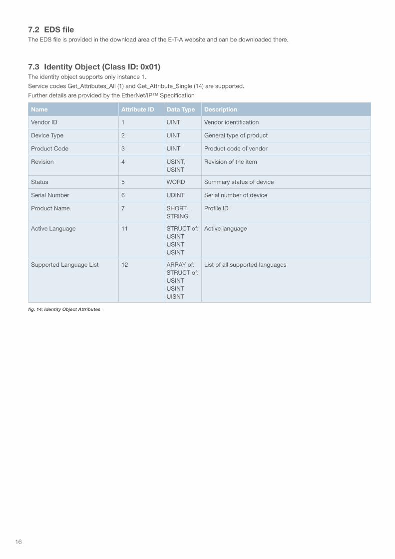
7.2 EDS fileThe EDS file is provided in the download area of the E-T-A website and can be downloaded there.
7.3 Identity Object (Class ID: 0x01)The identity object supports only instance 1.
Service codes Get_Attributes_All (1) and Get_Attribute_Single (14) are supported.
Further details are provided by the EtherNet/IP™ Specification
Name Attribute ID Data Type Description
Vendor ID 1 UINT Vendor identification
Device Type 2 UINT General type of product
Product Code 3 UINT Product code of vendor
Revision 4 USINT, USINT
Revision of the item
Status 5 WORD Summary status of device
Serial Number 6 UDINT Serial number of device
Product Name 7 SHORT_STRING
Profile ID
Active Language 11 STRUCT of:USINTUSINTUSINT
Active language
Supported Language List 12 ARRAY of:STRUCT of:USINTUSINTUISNT
List of all supported languages
fig. 14: Identity Object Attributes
17
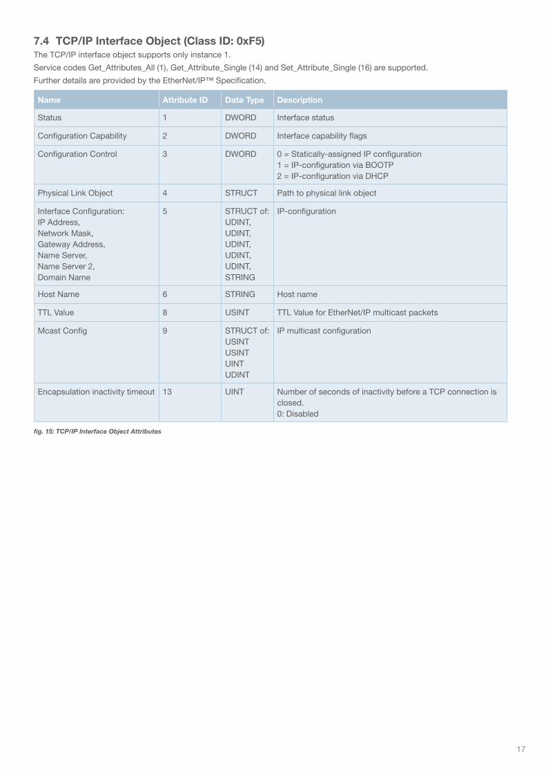
7.4 TCP/IP Interface Object (Class ID: 0xF5)The TCP/IP interface object supports only instance 1.
Service codes Get_Attributes_All (1), Get_Attribute_Single (14) and Set_Attribute_Single (16) are supported.
Further details are provided by the EtherNet/IP™ Specification.
Name Attribute ID Data Type Description
Status 1 DWORD Interface status
Configuration Capability 2 DWORD Interface capability flags
Configuration Control 3 DWORD 0 = Statically-assigned IP configuration1 = IP-configuration via BOOTP2 = IP-configuration via DHCP
Physical Link Object 4 STRUCT Path to physical link object
Interface Configuration:IP Address,Network Mask,Gateway Address,Name Server,Name Server 2,Domain Name
5 STRUCT of:UDINT,UDINT,UDINT,UDINT,UDINT,STRING
IP-configuration
Host Name 6 STRING Host name
TTL Value 8 USINT TTL Value for EtherNet/IP multicast packets
Mcast Config 9 STRUCT of:USINTUSINTUINTUDINT
IP multicast configuration
Encapsulation inactivity timeout 13 UINT Number of seconds of inactivity before a TCP connection is closed.0: Disabled
fig. 15: TCP/IP Interface Object Attributes
18
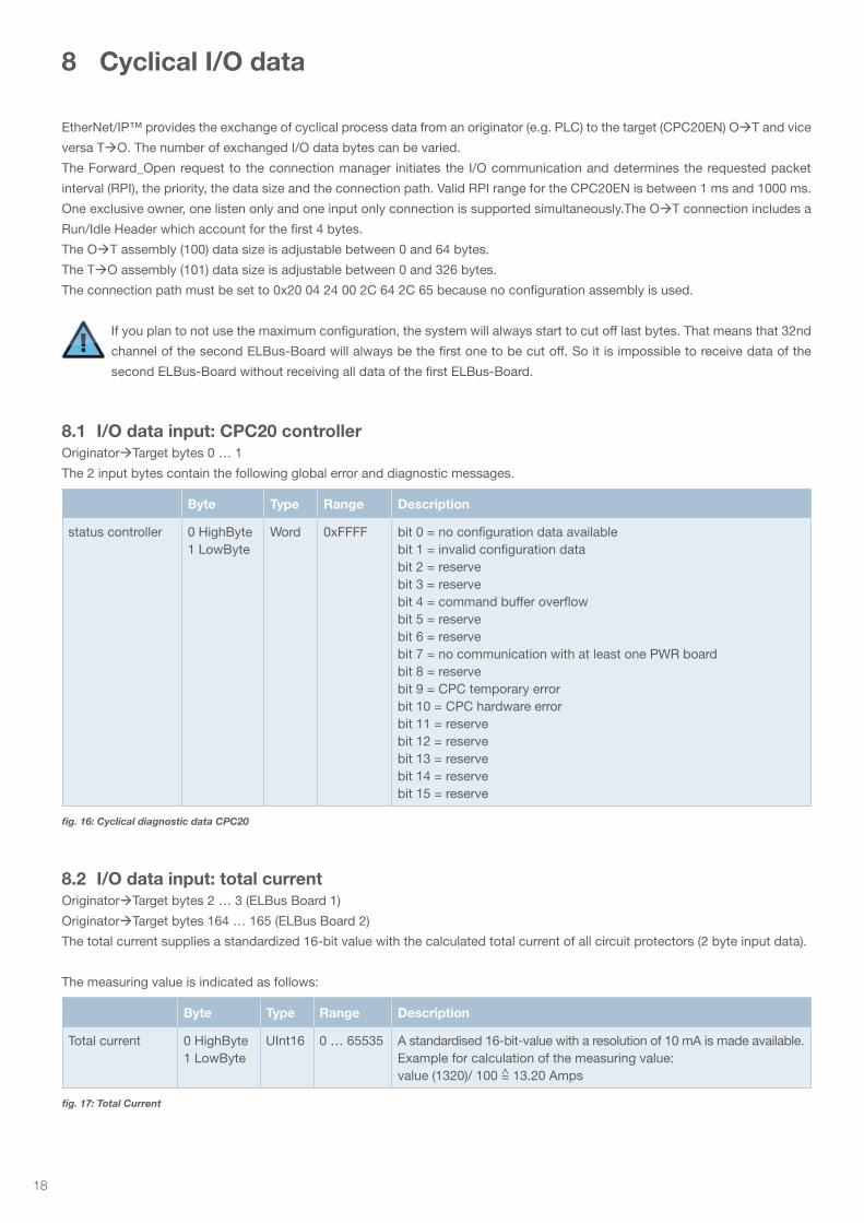
8 Cyclical I/O data
EtherNet/IP™ provides the exchange of cyclical process data from an originator (e.g. PLC) to the target (CPC20EN) OT and vice
versa TO. The number of exchanged I/O data bytes can be varied.
The Forward_Open request to the connection manager initiates the I/O communication and determines the requested packet
interval (RPI), the priority, the data size and the connection path. Valid RPI range for the CPC20EN is between 1 ms and 1000 ms.
One exclusive owner, one listen only and one input only connection is supported simultaneously.The OT connection includes a
Run/Idle Header which account for the first 4 bytes.
The OT assembly (100) data size is adjustable between 0 and 64 bytes.
The TO assembly (101) data size is adjustable between 0 and 326 bytes.
The connection path must be set to 0x20 04 24 00 2C 64 2C 65 because no configuration assembly is used.
If you plan to not use the maximum configuration, the system will always start to cut off last bytes. That means that 32nd
channel of the second ELBus-Board will always be the first one to be cut off. So it is impossible to receive data of the
second ELBus-Board without receiving all data of the first ELBus-Board.
8.1 I/O data input: CPC20 controllerOriginatorTarget bytes 0 … 1
The 2 input bytes contain the following global error and diagnostic messages.
8.2 I/O data input: total currentOriginatorTarget bytes 2 … 3 (ELBus Board 1)
OriginatorTarget bytes 164 … 165 (ELBus Board 2)
The total current supplies a standardized 16-bit value with the calculated total current of all circuit protectors (2 byte input data).
The measuring value is indicated as follows:
Byte Type Range Description
status controller 0 HighByte1 LowByte
Word 0xFFFF bit 0 = no configuration data availablebit 1 = invalid configuration databit 2 = reservebit 3 = reservebit 4 = command buffer overflowbit 5 = reservebit 6 = reservebit 7 = no communication with at least one PWR boardbit 8 = reservebit 9 = CPC temporary errorbit 10 = CPC hardware errorbit 11 = reservebit 12 = reservebit 13 = reservebit 14 = reservebit 15 = reserve
Byte Type Range Description
Total current 0 HighByte1 LowByte
UInt16 0 … 65535 A standardised 16-bit-value with a resolution of 10 mA is made available.Example for calculation of the measuring value: value (1320)/ 100 =̂ 13.20 Amps
fig. 16: Cyclical diagnostic data CPC20
fig. 17: Total Current
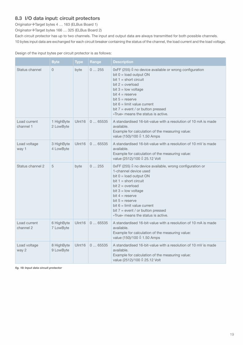
19
8.3 I/O data input: circuit protectorsOriginatorTarget bytes 4 … 163 (ELBus Board 1)
OriginatorTarget bytes 166 … 325 (ELBus Board 2)
Each circuit protector has up to two channels. The input and output data are always transmitted for both possible channels.
10 bytes input data are exchanged for each circuit breaker containing the status of the channel, the load current and the load voltage.
Design of the input bytes per circuit protector is as follows:
Byte Type Range Description
Status channel 0 byte 0 … 255 0xFF (255) =̂ no device available or wrong configuration bit 0 = load output ONbit 1 = short circuitbit 2 = overloadbit 3 = low voltagebit 4 = reservebit 5 = reservebit 6 = limit value currentbit 7 = event / or button pressed»True« means the status is active.
Load current channel 1
1 HighByte 2 LowByte
UInt16 0 … 65535 A standardised 16-bit-value with a resolution of 10 mA is made available.Example for calculation of the measuring value: value (150)/100 =̂ 1.50 Amps
Load voltage way 1
3 HighByte4 LowByte
UInt16 0 … 65535 A standardised 16-bit-value with a resolution of 10 mV is made available.Example for calculation of the measuring value: value (2512)/100 =̂ 25.12 Volt
Status channel 2 5 byte 0 … 255 0xFF (255) =̂ no device available, wrong configuration or 1-channel device usedbit 0 = load output ON bit 1 = short circuitbit 2 = overload bit 3 = low voltage bit 4 = reservebit 5 = reservebit 6 = limit value currentbit 7 = event / or button pressed»True« means the status is active.
Load current channel 2
6 HighByte7 LowByte
UInt16 0 … 65535 A standardised 16-bit-value with a resolution of 10 mA is made available.Example for calculation of the measuring value: value (150)/100 =̂ 1.50 Amps
Load voltage way 2
8 HighByte9 LowByte
UInt16 0 … 65535 A standardised 16-bit-value with a resolution of 10 mV is made available.Example for calculation of the measuring value: value (2512)/100 =̂ 25.12 Volt
fig. 18: Input data circuit protector
20
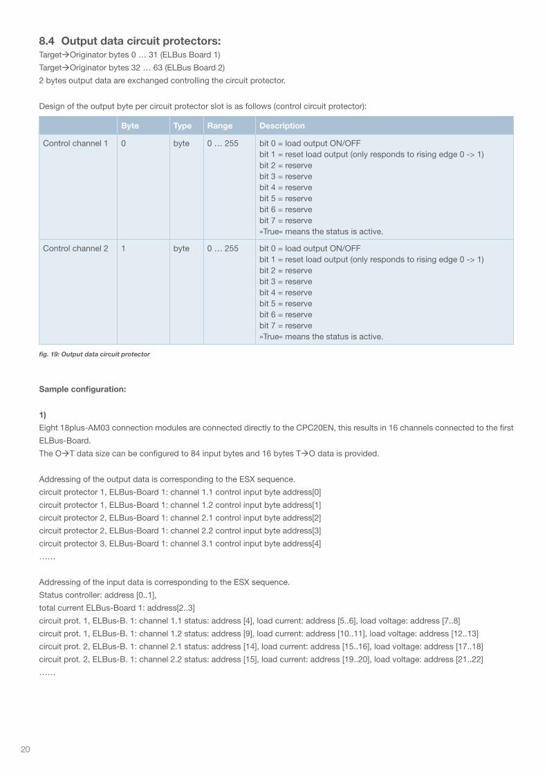
8.4 Output data circuit protectors:TargetOriginator bytes 0 … 31 (ELBus Board 1)
TargetOriginator bytes 32 … 63 (ELBus Board 2)
2 bytes output data are exchanged controlling the circuit protector.
Design of the output byte per circuit protector slot is as follows (control circuit protector):
Sample configuration:
1)
Eight 18plus-AM03 connection modules are connected directly to the CPC20EN, this results in 16 channels connected to the first
ELBus-Board.
The OT data size can be configured to 84 input bytes and 16 bytes TO data is provided.
Addressing of the output data is corresponding to the ESX sequence.
circuit protector 1, ELBus-Board 1: channel 1.1 control input byte address[0]
circuit protector 1, ELBus-Board 1: channel 1.2 control input byte address[1]
circuit protector 2, ELBus-Board 1: channel 2.1 control input byte address[2]
circuit protector 2, ELBus-Board 1: channel 2.2 control input byte address[3]
circuit protector 3, ELBus-Board 1: channel 3.1 control input byte address[4]
……
Addressing of the input data is corresponding to the ESX sequence.
Status controller: address [0..1],
total current ELBus-Board 1: address[2..3]
circuit prot. 1, ELBus-B. 1: channel 1.1 status: address [4], load current: address [5..6], load voltage: address [7..8]
circuit prot. 1, ELBus-B. 1: channel 1.2 status: address [9], load current: address [10..11], load voltage: address [12..13]
circuit prot. 2, ELBus-B. 1: channel 2.1 status: address [14], load current: address [15..16], load voltage: address [17..18]
circuit prot. 2, ELBus-B. 1: channel 2.2 status: address [15], load current: address [19..20], load voltage: address [21..22]
……
Byte Type Range Description
Control channel 1 0 byte 0 … 255 bit 0 = load output ON/OFFbit 1 = reset load output (only responds to rising edge 0 -> 1) bit 2 = reservebit 3 = reserve bit 4 = reserve bit 5 = reserve bit 6 = reserve bit 7 = reserve»True« means the status is active.
Control channel 2 1 byte 0 … 255 bit 0 = load output ON/OFFbit 1 = reset load output (only responds to rising edge 0 -> 1) bit 2 = reservebit 3 = reserve bit 4 = reserve bit 5 = reserve bit 6 = reserve bit 7 = reserve»True« means the status is active.
fig. 19: Output data circuit protector

21
2)
Eight 18plus-AM03 connection modules are connected directly to the CPC20EN, this results in 16 channels connected to the first
ELBus-Board. Eight 18plus-AM03 connection modules are connected to the second ELBus-Port of the CPC20EN, this results in
16 channels connected to the second ELBus-Board.
The OT data size can be configured to 244 input bytes and 48 bytes TO data is provided.
Addressing of the output data is corresponding to the ESX sequence.
circuit protector 1, ELBus-Board 1: channel 1.1 control input byte address[0]
circuit protector 1, ELBus-Board 1: channel 1.2 control input byte address[1]
circuit protector 2, ELBus-Board 1: channel 2.1 control input byte address[2]
……
circuit protector 16, ELBus-Board 1: channel 32.2 control input byte address[31]
circuit protector 1, ELBus-Board 2: channel 1.1 control input byte address[32]
circuit protector 1, ELBus-Board 2: channel 1.2 control input byte address[33]
……
circuit protector 8, ELBus-Board 2: channel 8.2 control input byte address[47]
Addressing of the input data is corresponding to the ESX sequence.
Status controller: address [0..1],
total current: address[2..3]
circuit prot. 1, ELBus-B. 1: channel 1.1 status: address [4], load current: address [5..6], load voltage: address [7..8]
circuit prot. 1, ELBus-B. 1: channel 1.2 status: address [9], load current: address [10..11], load voltage: address [12..13]
circuit prot. 2, ELBus-B. 1: channel 2.1 status: address [14], load current: address [15..16], load voltage: address [17..18]
……
circuit prot. 16, ELBus-B. 1: channel 32.2 status: address [159], load current: address [160..161], load voltage: address [162..163]
total current ELBus-Board 2: address[164..165]
circuit prot. 1, ELBus-B. 2: channel 1.1 status: address [166], load current: address [167..168], load voltage: address [169..170]
circuit prot. 1, ELBus-B. 2: channel 1.2 status: address [171], load current: address [172..173], load voltage: address [174..175]
…….
circuit prot. 8, ELBus-B. 2: channel 8.2 status: address [201], load current: address [202..203], load voltage: address [204..205]
22
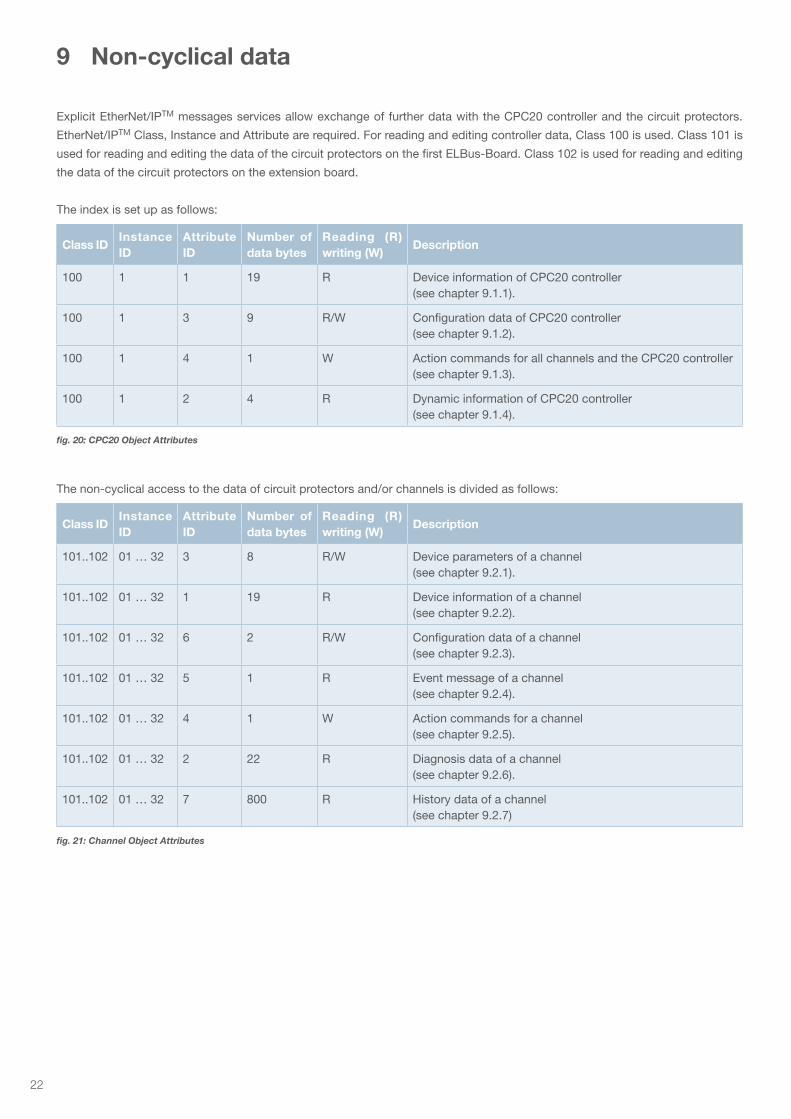
9 Non-cyclical data
Explicit EtherNet/IPTM messages services allow exchange of further data with the CPC20 controller and the circuit protectors.
EtherNet/IPTM Class, Instance and Attribute are required. For reading and editing controller data, Class 100 is used. Class 101 is
used for reading and editing the data of the circuit protectors on the first ELBus-Board. Class 102 is used for reading and editing
the data of the circuit protectors on the extension board.
The index is set up as follows:
The non-cyclical access to the data of circuit protectors and/or channels is divided as follows:
Class IDInstance ID
Attribute ID
Number of data bytes
Reading (R) writing (W)
Description
100 1 1 19 R Device information of CPC20 controller (see chapter 9.1.1).
100 1 3 9 R/W Configuration data of CPC20 controller (see chapter 9.1.2).
100 1 4 1 W Action commands for all channels and the CPC20 controller (see chapter 9.1.3).
100 1 2 4 R Dynamic information of CPC20 controller (see chapter 9.1.4).
Class IDInstance ID
Attribute ID
Number of data bytes
Reading (R) writing (W)
Description
101..102 01 … 32 3 8 R/W Device parameters of a channel (see chapter 9.2.1).
101..102 01 … 32 1 19 R Device information of a channel (see chapter 9.2.2).
101..102 01 … 32 6 2 R/W Configuration data of a channel (see chapter 9.2.3).
101..102 01 … 32 5 1 R Event message of a channel (see chapter 9.2.4).
101..102 01 … 32 4 1 W Action commands for a channel (see chapter 9.2.5).
101..102 01 … 32 2 22 R Diagnosis data of a channel (see chapter 9.2.6).
101..102 01 … 32 7 800 R History data of a channel (see chapter 9.2.7)
fig. 20: CPC20 Object Attributes
fig. 21: Channel Object Attributes
23
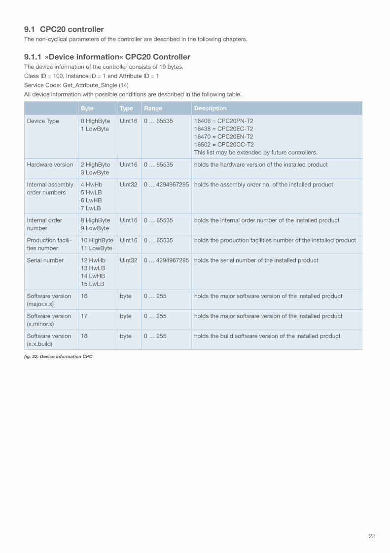
9.1 CPC20 controllerThe non-cyclical parameters of the controller are described in the following chapters.
9.1.1 »Device information« CPC20 ControllerThe device information of the controller consists of 19 bytes.
Class ID = 100, Instance ID = 1 and Attribute ID = 1
Service Code: Get_Attribute_Single (14)
All device information with possible conditions are described in the following table.
Byte Type Range Description
Device Type 0 HighByte1 LowByte
UInt16 0 … 65535 16406 = CPC20PN-T216438 = CPC20EC-T216470 = CPC20EN-T216502 = CPC20CC-T2This list may be extended by future controllers.
Hardware version 2 HighByte3 LowByte
UInt16 0 … 65535 holds the hardware version of the installed product
Internal assembly order numbers
4 HwHb5 HwLB6 LwHB7 LwLB
UInt32 0 … 4294967295 holds the assembly order no. of the installed product
Internal order number
8 HighByte9 LowByte
UInt16 0 … 65535 holds the internal order number of the installed product
Production facili-ties number
10 HighByte11 LowByte
UInt16 0 … 65535 holds the production facilities number of the installed product
Serial number 12 HwHb13 HwLB14 LwHB15 LwLB
UInt32 0 … 4294967295 holds the serial number of the installed product
Software version (major.x.x)
16 byte 0 … 255 holds the major software version of the installed product
Software version (x.minor.x)
17 byte 0 … 255 holds the major software version of the installed product
Software version (x.x.build)
18 byte 0 … 255 holds the build software version of the installed product
fig. 22: Device information CPC
24
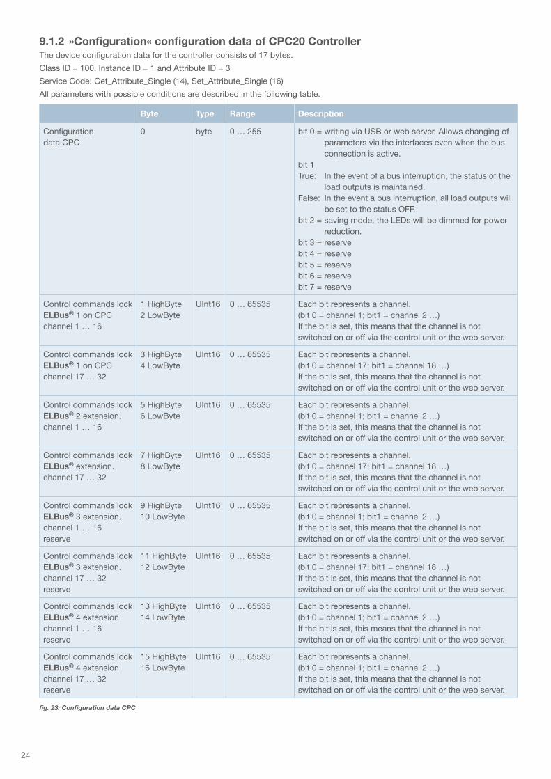
Byte Type Range Description
Configuration data CPC
0 byte 0 … 255 bit 0 = writing via USB or web server. Allows changing of parameters via the interfaces even when the bus connection is active.
bit 1True: In the event of a bus interruption, the status of the
load outputs is maintained.False: In the event a bus interruption, all load outputs will
be set to the status OFF.bit 2 = saving mode, the LEDs will be dimmed for power
reduction.bit 3 = reservebit 4 = reservebit 5 = reservebit 6 = reserve bit 7 = reserve
Control commands lock ELBus® 1 on CPC channel 1 … 16
1 HighByte2 LowByte
UInt16 0 … 65535 Each bit represents a channel.(bit 0 = channel 1; bit1 = channel 2 …)If the bit is set, this means that the channel is not switched on or off via the control unit or the web server.
Control commands lock ELBus® 1 on CPC channel 17 … 32
3 HighByte4 LowByte
UInt16 0 … 65535 Each bit represents a channel.(bit 0 = channel 17; bit1 = channel 18 …)If the bit is set, this means that the channel is not switched on or off via the control unit or the web server.
Control commands lock ELBus® 2 extension. channel 1 … 16
5 HighByte6 LowByte
UInt16 0 … 65535 Each bit represents a channel.(bit 0 = channel 1; bit1 = channel 2 …)If the bit is set, this means that the channel is not switched on or off via the control unit or the web server.
Control commands lock ELBus® extension.channel 17 … 32
7 HighByte8 LowByte
UInt16 0 … 65535 Each bit represents a channel.(bit 0 = channel 17; bit1 = channel 18 …)If the bit is set, this means that the channel is not switched on or off via the control unit or the web server.
Control commands lock ELBus® 3 extension.channel 1 … 16 reserve
9 HighByte10 LowByte
UInt16 0 … 65535 Each bit represents a channel.(bit 0 = channel 1; bit1 = channel 2 …)If the bit is set, this means that the channel is not switched on or off via the control unit or the web server.
Control commands lock ELBus® 3 extension.channel 17 … 32 reserve
11 HighByte12 LowByte
UInt16 0 … 65535 Each bit represents a channel.(bit 0 = channel 17; bit1 = channel 18 …)If the bit is set, this means that the channel is not switched on or off via the control unit or the web server.
Control commands lock ELBus® 4 extension channel 1 … 16 reserve
13 HighByte14 LowByte
UInt16 0 … 65535 Each bit represents a channel.(bit 0 = channel 1; bit1 = channel 2 …)If the bit is set, this means that the channel is not switched on or off via the control unit or the web server.
Control commands lock ELBus® 4 extension channel 17 … 32 reserve
15 HighByte16 LowByte
UInt16 0 … 65535 Each bit represents a channel.(bit 0 = channel 1; bit1 = channel 2 …)If the bit is set, this means that the channel is not switched on or off via the control unit or the web server.
fig. 23: Configuration data CPC
9.1.2 »Configuration« configuration data of CPC20 ControllerThe device configuration data for the controller consists of 17 bytes.
Class ID = 100, Instance ID = 1 and Attribute ID = 3
Service Code: Get_Attribute_Single (14), Set_Attribute_Single (16)
All parameters with possible conditions are described in the following table.
25
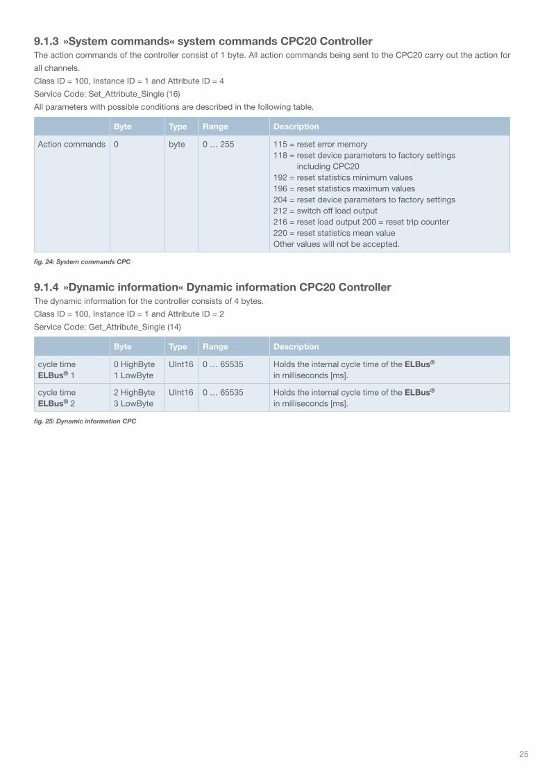
9.1.3 »System commands« system commands CPC20 ControllerThe action commands of the controller consist of 1 byte. All action commands being sent to the CPC20 carry out the action for
all channels.
Class ID = 100, Instance ID = 1 and Attribute ID = 4
Service Code: Set_Attribute_Single (16)
All parameters with possible conditions are described in the following table.
9.1.4 »Dynamic information« Dynamic information CPC20 ControllerThe dynamic information for the controller consists of 4 bytes.
Class ID = 100, Instance ID = 1 and Attribute ID = 2
Service Code: Get_Attribute_Single (14)
Byte Type Range Description
Action commands 0 byte 0 … 255 115 = reset error memory118 = reset device parameters to factory settings
including CPC20192 = reset statistics minimum values196 = reset statistics maximum values204 = reset device parameters to factory settings 212 = switch off load output216 = reset load output 200 = reset trip counter220 = reset statistics mean value Other values will not be accepted.
Byte Type Range Description
cycle time ELBus® 1
0 HighByte1 LowByte
UInt16 0 … 65535 Holds the internal cycle time of the ELBus® in milliseconds [ms].
cycle time ELBus® 2
2 HighByte3 LowByte
UInt16 0 … 65535 Holds the internal cycle time of the ELBus® in milliseconds [ms].
fig. 24: System commands CPC
fig. 25: Dynamic information CPC
26
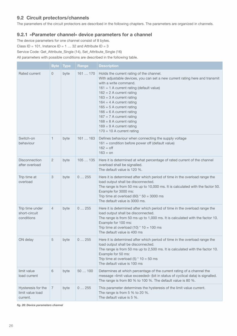
9.2 Circuit protectors/channelsThe parameters of the circuit protectors are described in the following chapters. The parameters are organized in channels.
9.2.1 »Parameter channel« device parameters for a channelThe device parameters for one channel consist of 8 bytes.
Class ID = 101, Instance ID = 1 … 32 and Attribute ID = 3
Service Code: Get_Attribute_Single (14), Set_Attribute_Single (16)
All parameters with possible conditions are described in the following table.
Byte Type Range Description
Rated current 0 byte 161 … 170 Holds the current rating of the channel.With adjustable devices, you can set a new current rating here and transmit with a write command.161 = 1 A current rating (default value)162 = 2 A current rating163 = 3 A current rating164 = 4 A current rating165 = 5 A current rating166 = 6 A current rating167 = 7 A current rating168 = 8 A current rating169 = 9 A current rating170 = 10 A current rating
Switch-onbehaviour
1 byte 161 … 163 Defines behaviour when connecting the supply voltage161 = condition before power off (default value)162 = off163 = on
Disconnection after overload
2 byte 105 … 135 Here it is determined at what percentage of rated current of the channel overload shall be signalled.The default value is 120 %.
Trip time at overload
3 byte 0 … 255 Here it is determined after which period of time in the overload range the load output shall be disconnected.The range is from 50 ms up to 10,000 ms. It is calculated with the factor 50.Example for 3000 ms:Trip time at overload (60) * 50 = 3000 msThe default value is 3000 ms.
Trip time under short-circuit conditions
4 byte 0 … 255 Here it is determined after which period of time in the overload range the load output shall be disconnected.The range is from 50 ms up to 1,000 ms. It is calculated with the factor 10.Example for 100 ms:Trip time at overload (10) * 10 = 100 msThe default value is 400 ms
ON delay 5 byte 0 … 255 Here it is determined after which period of time in the overload range the load output shall be disconnected.The range is from 50 ms up to 2,500 ms. It is calculated with the factor 10.Example for 50 ms:Trip time at overload (5) * 10 = 50 msThe default value is 100 ms
limit value load current
6 byte 50 … 100 Determines at which percentage of the current rating of a channel the message »limit value exceeded« (bit in status of cyclical data) is signalled. The range is from 80 % to 100 %. The default value is 80 %.
Hysteresis for the limit value load current.
7 byte 0 … 255 This parameter determines the hysteresis of the limit value current.The range is from 5 % to 20 %.The default value is 5 %.
fig. 26: Device parameters channel
27
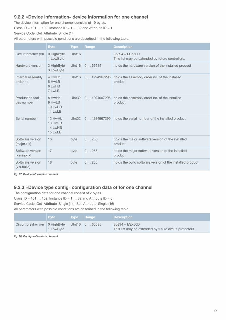
9.2.2 »Device information« device information for one channelThe device information for one channel consists of 19 bytes.
Class ID = 101 … 102, Instance ID = 1 … 32 and Attribute ID = 1
Service Code: Get_Attribute_Single (14)
All parameters with possible conditions are described in the following table.
9.2.3 »Device type config« configuration data of for one channelThe configuration data for one channel consist of 2 bytes.
Class ID = 101 … 102, Instance ID = 1 … 32 and Attribute ID = 6
Service Code: Get_Attribute_Single (14), Set_Attribute_Single (16)
All parameters with possible conditions are described in the following table.
Byte Type Range Description
Circuit breaker p/n 0 HighByte1 LowByte
UInt16 36894 = ESX60DThis list may be extended by future controllers.
Hardware version 2 HighByte3 LowByte
UInt16 0 … 65535 holds the hardware version of the installed product
Internal assembly order no.
4 HwHb5 HwLB6 LwHB7 LwLB
UInt16 0 … 4294967295 holds the assembly order no. of the installed product
Production facili-ties number
8 HwHb9 HwLB10 LwHB11 LwLB
UInt32 0 … 4294967295 holds the assembly order no. of the installed product
Serial number 12 HwHb13 HwLB14 LwHB15 LwLB
UInt32 0 … 4294967295 holds the serial number of the installed product
Software version (major.x.x)
16 byte 0 … 255 holds the major software version of the installed product
Software version (x.minor.x)
17 byte 0 … 255 holds the major software version of the installed product
Software version (x.x.build)
18 byte 0 … 255 holds the build software version of the installed product
Byte Type Range Description
Circuit breaker p/n 0 HighByte1 LowByte
UInt16 0 … 65535 36894 = ESX60DThis list may be extended by future circuit protectors.
fig. 27: Device information channel
fig. 28: Configuration data channel
28
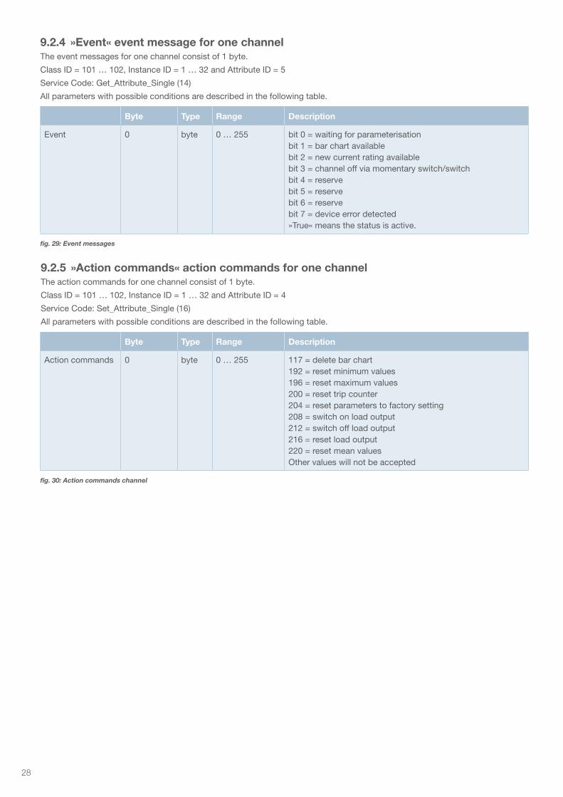
9.2.4 »Event« event message for one channelThe event messages for one channel consist of 1 byte.
Class ID = 101 … 102, Instance ID = 1 … 32 and Attribute ID = 5
Service Code: Get_Attribute_Single (14)
All parameters with possible conditions are described in the following table.
9.2.5 »Action commands« action commands for one channelThe action commands for one channel consist of 1 byte.
Class ID = 101 … 102, Instance ID = 1 … 32 and Attribute ID = 4
Service Code: Set_Attribute_Single (16)
All parameters with possible conditions are described in the following table.
Byte Type Range Description
Event 0 byte 0 … 255 bit 0 = waiting for parameterisation bit 1 = bar chart availablebit 2 = new current rating availablebit 3 = channel off via momentary switch/switchbit 4 = reservebit 5 = reservebit 6 = reservebit 7 = device error detected»True« means the status is active.
Byte Type Range Description
Action commands 0 byte 0 … 255 117 = delete bar chart 192 = reset minimum values 196 = reset maximum values 200 = reset trip counter 204 = reset parameters to factory setting 208 = switch on load output212 = switch off load output 216 = reset load output 220 = reset mean values Other values will not be accepted
fig. 30: Action commands channel
fig. 29: Event messages
29
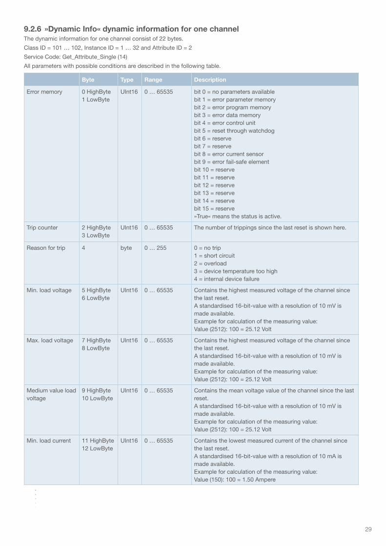
Byte Type Range Description
Error memory 0 HighByte1 LowByte
UInt16 0 … 65535 bit 0 = no parameters availablebit 1 = error parameter memorybit 2 = error program memorybit 3 = error data memorybit 4 = error control unitbit 5 = reset through watchdogbit 6 = reservebit 7 = reservebit 8 = error current sensorbit 9 = error fail-safe elementbit 10 = reservebit 11 = reservebit 12 = reservebit 13 = reservebit 14 = reservebit 15 = reserve»True« means the status is active.
Trip counter 2 HighByte3 LowByte
UInt16 0 … 65535 The number of trippings since the last reset is shown here.
Reason for trip 4 byte 0 … 255 0 = no trip1 = short circuit2 = overload3 = device temperature too high4 = internal device failure
Min. load voltage 5 HighByte6 LowByte
UInt16 0 … 65535 Contains the highest measured voltage of the channel since the last reset.A standardised 16-bit-value with a resolution of 10 mV is made available.Example for calculation of the measuring value:Value (2512): 100 = 25.12 Volt
Max. load voltage 7 HighByte8 LowByte
UInt16 0 … 65535 Contains the highest measured voltage of the channel since the last reset.A standardised 16-bit-value with a resolution of 10 mV is made available.Example for calculation of the measuring value:Value (2512): 100 = 25.12 Volt
Medium value load voltage
9 HighByte10 LowByte
UInt16 0 … 65535 Contains the mean voltage value of the channel since the last reset.A standardised 16-bit-value with a resolution of 10 mV is made available.Example for calculation of the measuring value:Value (2512): 100 = 25.12 Volt
Min. load current 11 HighByte12 LowByte
UInt16 0 … 65535 Contains the lowest measured current of the channel since the last reset.A standardised 16-bit-value with a resolution of 10 mA is made available.Example for calculation of the measuring value:Value (150): 100 = 1.50 Ampere
9.2.6 »Dynamic Info« dynamic information for one channelThe dynamic information for one channel consist of 22 bytes.
Class ID = 101 … 102, Instance ID = 1 … 32 and Attribute ID = 2
Service Code: Get_Attribute_Single (14)
All parameters with possible conditions are described in the following table.
30
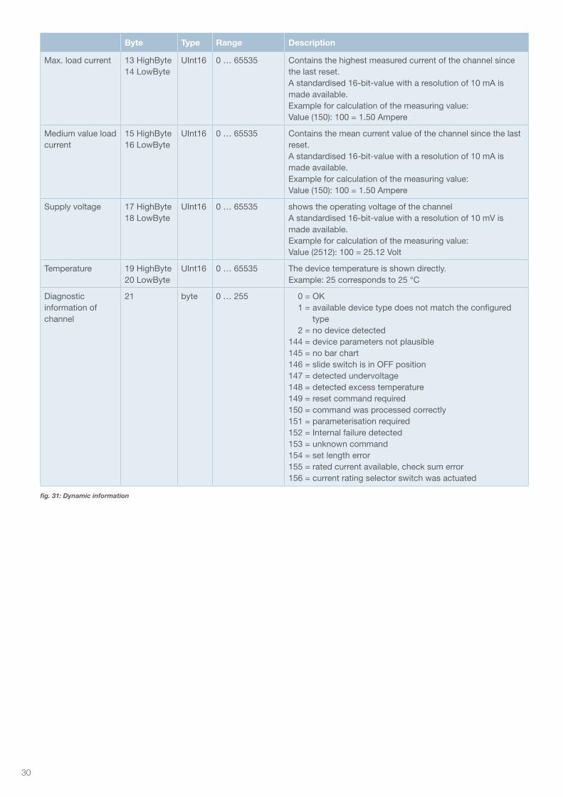
Byte Type Range Description
Max. load current 13 HighByte14 LowByte
UInt16 0 … 65535 Contains the highest measured current of the channel since the last reset.A standardised 16-bit-value with a resolution of 10 mA is made available.Example for calculation of the measuring value:Value (150): 100 = 1.50 Ampere
Medium value load current
15 HighByte16 LowByte
UInt16 0 … 65535 Contains the mean current value of the channel since the last reset.A standardised 16-bit-value with a resolution of 10 mA is made available.Example for calculation of the measuring value:Value (150): 100 = 1.50 Ampere
Supply voltage 17 HighByte18 LowByte
UInt16 0 … 65535 shows the operating voltage of the channelA standardised 16-bit-value with a resolution of 10 mV is made available.Example for calculation of the measuring value:Value (2512): 100 = 25.12 Volt
Temperature 19 HighByte20 LowByte
UInt16 0 … 65535 The device temperature is shown directly.Example: 25 corresponds to 25 °C
Diagnosticinformation of channel
21 byte 0 … 255 0 = OK 1 = available device type does not match the configured
type 2 = no device detected144 = device parameters not plausible145 = no bar chart146 = slide switch is in OFF position147 = detected undervoltage148 = detected excess temperature149 = reset command required150 = command was processed correctly151 = parameterisation required152 = Internal failure detected153 = unknown command154 = set length error155 = rated current available, check sum error156 = current rating selector switch was actuated
fig. 31: Dynamic information
31
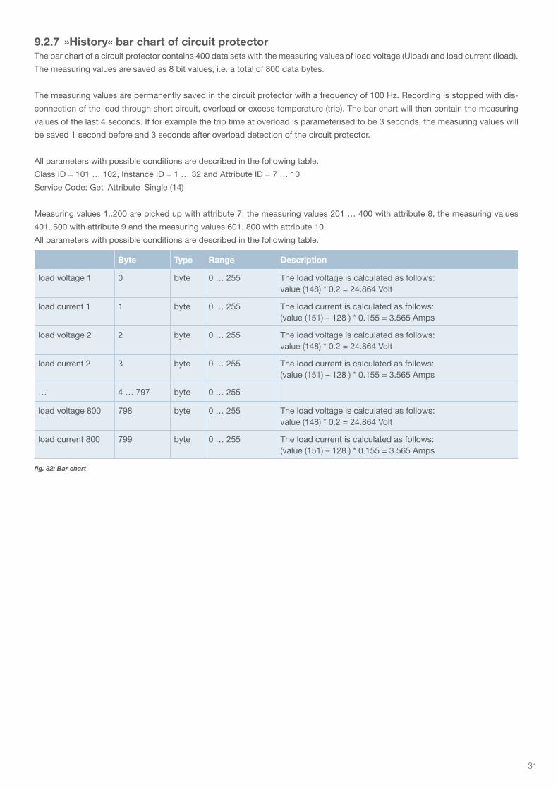
9.2.7 »History« bar chart of circuit protectorThe bar chart of a circuit protector contains 400 data sets with the measuring values of load voltage (Uload) and load current (Iload).
The measuring values are saved as 8 bit values, i.e. a total of 800 data bytes.
The measuring values are permanently saved in the circuit protector with a frequency of 100 Hz. Recording is stopped with dis-
connection of the load through short circuit, overload or excess temperature (trip). The bar chart will then contain the measuring
values of the last 4 seconds. If for example the trip time at overload is parameterised to be 3 seconds, the measuring values will
be saved 1 second before and 3 seconds after overload detection of the circuit protector.
All parameters with possible conditions are described in the following table.
Class ID = 101 … 102, Instance ID = 1 … 32 and Attribute ID = 7 … 10
Service Code: Get_Attribute_Single (14)
Measuring values 1..200 are picked up with attribute 7, the measuring values 201 … 400 with attribute 8, the measuring values
401..600 with attribute 9 and the measuring values 601..800 with attribute 10.
All parameters with possible conditions are described in the following table.
Byte Type Range Description
load voltage 1 0 byte 0 … 255 The load voltage is calculated as follows:value (148) * 0.2 = 24.864 Volt
load current 1 1 byte 0 … 255 The load current is calculated as follows:(value (151) – 128 ) * 0.155 = 3.565 Amps
load voltage 2 2 byte 0 … 255 The load voltage is calculated as follows:value (148) * 0.2 = 24.864 Volt
load current 2 3 byte 0 … 255 The load current is calculated as follows:(value (151) – 128 ) * 0.155 = 3.565 Amps
… 4 … 797 byte 0 … 255
load voltage 800 798 byte 0 … 255 The load voltage is calculated as follows:value (148) * 0.2 = 24.864 Volt
load current 800 799 byte 0 … 255 The load current is calculated as follows:(value (151) – 128 ) * 0.155 = 3.565 Amps
fig. 32: Bar chart
32
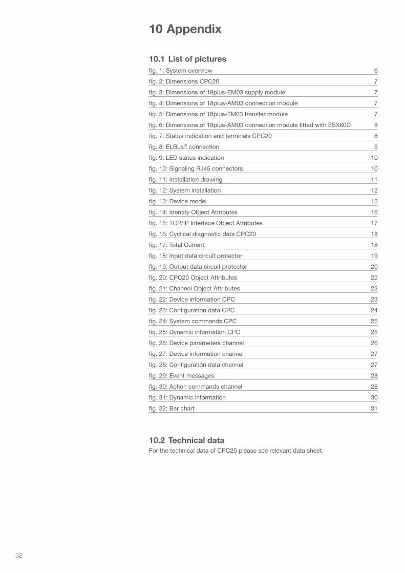
10 Appendix
10.1 List of picturesfig. 1: System overview 6
fig. 2: Dimensions CPC20 7
fig. 3: Dimensions of 18plus-EM03 supply module 7
fig. 4: Dimensions of 18plus-AM03 connection module 7
fig. 5: Dimensions of 18plus-TM03 transfer module 7
fig. 6: Dimensions of 18plus-AM03 connection module fitted with ESX60D 8
fig. 7: Status indication and terminals CPC20 8
fig. 8: ELBus® connection 9
fig. 9: LED status indication 10
fig. 10: Signaling RJ45 connectors 10
fig. 11: Installation drawing 11
fig. 12: System installation 12
fig. 13: Device model 15
fig. 14: Identity Object Attributes 16
fig. 15: TCP/IP Interface Object Attributes 17
fig. 16: Cyclical diagnostic data CPC20 18
fig. 17: Total Current 18
fig. 18: Input data circuit protector 19
fig. 19: Output data circuit protector 20
fig. 20: CPC20 Object Attributes 22
fig. 21: Channel Object Attributes 22
fig. 22: Device information CPC 23
fig. 23: Configuration data CPC 24
fig. 24: System commands CPC 25
fig. 25: Dynamic information CPC 25
fig. 26: Device parameters channel 26
fig. 27: Device information channel 27
fig. 28: Configuration data channel 27
fig. 29: Event messages 28
fig. 30: Action commands channel 28
fig. 31: Dynamic information 30
fig. 32: Bar chart 31
10.2 Technical dataFor the technical data of CPC20 please see relevant data sheet.

33
Notes

34
Notes

35
Notes

E-T-A Elektrotechnische Apparate GmbH Industriestraße 2-8 . 90518 Altdorf GERMANYPhone +49 9187 10-0 . Fax +49 9187 10-397E-Mail: [email protected] . www.e-t-a.de
Bedienungsanleitung/Instruction manual CPC20EN (ENG)Bestell-Nr. / Ref. number Y31363502 - Index: -Issue 02/2021Alle Rechte vorbehalten / All rights reserved
www.e-t-a.de/QR1036