Embed Size (px)
Citation preview

CO2 Generators: 4, 8, and 10 Burner Models
U S E R M A N UA L
CO 2 G E N E R ATO R S ( A L L M O D E L S )

Thank you for purchasing the Autopilot CO2 Generator. Please read and understand this instruction manual BEFORE attempting to operate this product. Failure to do so could result in personal injury and/or property damage.
Carbon dioxide enrichment stimulates the growth and development of nearly all plants. Elevated atmospheric CO
2 levels show remarkable increases in plant growth productivity, it is simply the
easiest way to accelerate plant growth. The Autopilot CO2 Generators provide and maintain the
carbon dioxide levels needed to meet maximum growing potential, and operate for only pennies a day.
Autopilot CO2 generators feature powder-coated steel enclosures that resist moisture, rust and
discoloration - providing years of trouble-free operation.
The solid state electronic ignition module creates a spark to light the burners. Autopilot generators are available in both propane and natural gas models, along with high altitude versions in all sizes.
All models are equipped with:
• Precision manufactured brass burners• Solid state electronic ignition module—no pilot light necessary• TIP OVER switch shuts off gas source if the unit falls or tips over• SHUT DOWN warning with LED error indicator light
The CO2 generators are perfectly paired with our Autopilot line of environmental controllers. Visit
Autopilotcontrollers.com to find the right CO2 controller for your grow room or greenhouse.
INSTALLATION PROCEDURES START ON PAGE 10 OF THIS BOOKLET.
WARNING!!
If the information in this manual is not followed exactly, a fire or explosion could result, causing property damage, personal injury or
loss of life. Please read through entire user manual before beginning the installation procedure.
TOOLS NEEDED - (FOR INSTALLATION)
PhillipsScrewdriver
AdjustableWrench
Pliers Level Ladder3/4" Open End Wrench
2
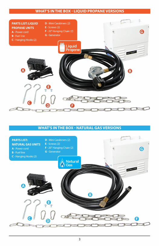
PARTS LIST: LIQUID PROPANE UNITSA - Power cordB - Fuel lineC - Hanging Hooks (2)
D - Mini Carabiners (2)E - Screws (2)F - 20" Hanging Chain (2)G - Generator
A B
F
E
CD
G
PARTS LIST: NATURAL GAS UNITSA - Power cordB - Fuel lineC - Hanging Hooks (2)
D - Mini Carabiners (2)E - Screws (2)F - 20" Hanging Chain (2)G - Generator
A
B
F
E
CD
G
WHAT’S IN THE BOX - LIQUID PROPANE VERSIONS
WHAT’S IN THE BOX - NATURAL GAS VERSIONS
3

There are 2 types of generators available, Natural Gas (NG) or Liquid Propane (LP). Both units come with the correct regulator and hose, along with pre-installed, clean-burning brass burners. Both units are equipped with features like a safety tilt switch, to automatically turn off the unit completely should it tip over or fall. An electronic ignition eliminates the need for a pilot flame.
Liquid Propane or LP is stored in various size pressurized tanks. The supplied LP regulator (which is designed to connect directly to portable LP tanks) MUST be used. The propane gas supply to the LP generator must be a regulated to a very low pressure of 11” WC or 1/2 PSI.
NOTE: Large outside propane tanks can be used as long as the propane gas pressure has been verified to be regulated at 11” WC*
*The standard for measuring low pressure is “INCHES WC” or inches of water column.
Natural Gas or NG is provided from a major pipeline and directly piped into homes and businesses. Because the incoming gas pressure can vary from less than 1/4 PSI to more than 5 PSI, the provided regulator MUST be used (unless the natural gas pressure has been verified and is regulated at 4.5" WC). The natural gas supply to the NG generator must be regulated to a very low pressure of 4.5" WC or 1/4 PSI.
WARNING!! Installation and connection of the gas lines must be completed in compliance with local and national building codes. Consult your local authorities for detailed requirements.
LIQUID PROPANE OR NATURAL GAS
4

CO2 Controller
CO2 MonitorCO2 Generator
PowerSupply
Supply Hose
TYPICALNATURAL GASSUPPLY LINE
CONFIGURATION
CO2 GENERATOR USING NATURAL GAS SUPPLY LINE
NOTE: This unit must be suspended from ceiling using the hanging kit.
CO2 Controller
CO2 MonitorCO2 Generator
PowerSupply
Supply Hosew/Regulator
TYPICALLIQUID PROPANE
SUPPLY LINECONFIGURATION
CO2 GENERATOR USING LIQUID PROPANE TANK
5
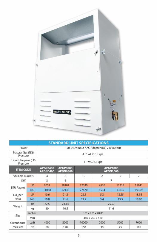
STANDARD UNIT SPECIFICATIONSPower 120-240V input / AC Adapter (UL) 24V output
Natural Gas (NG) Pressure 4.5" WC/1.15 kpa
Liquid Propane (LP) Pressure 11" WC/2.8 kpa
ITEM CODE APGP0400 APGN0400
APGP0800 APGN0800
APGP1000 APGN1000
Variable Burners 4 8 10 2 5 7
KW 3 6 7
BTU RatingLP 9052 18104 22630 4526 11315 15841
NG 11068 22136 27670 5534 13835 19369
CO2 per
HourLP 10.6 21.2 26.5 5.3 13.25 18.55
NG 10.8 21.6 27.7 5.4 13.5 18.90
Weightlbs 22.5 23.14 25.57
kg 10 10.5 11.6
Sizeinches 15” x 9.8” x 20.0”
mm 380 x 250 x 510
Greenhouse max size
cu ft 4000 8000 10000 2000 5000 7000
m3 60 120 150 30 75 105
6

The standard brass burners have been designed to operate correctly at an altitude between sea level and 4500 feet of elevation. If you are at an altitude higher than 4500', do not use the standard unit if yellow flames are visible. HA (High Altitude) burners are available by contacting the manufacturer.
If you are using the HA version of the generator, the burners are designed to run leaner so that the lower oxygen level at altitude will not affect the proper and complete combustion of the fuel. As a result of the lean burner calibration, the HA version of the generator is going to produce lower CO2 output.
The standard NG and LP brass burners have been designed to produce approximately 3 cu ft of CO2 per hour. When the HA (high-altitude) burners are used, the CO2 output and BTU of each burner is reduced by approximately 15%.
The HA units can be used at lower than 4500' (down to as low as 2500') elevation as long as the burners are lighting (igniting) correctly. If using the HA unit at lower elevations, first ensure that all burners are lighting correctly and consistently before use.
WARNING!! Verify that the burners are operating correctly.
• A burner that burns almost invisibly with a clean blue-white flame is running correctly.• A burner that is burning very yellow indicates a rich condition, or possibly low oxygen levels.• Burners that do not consistently ignite could be clogged or might not be receiving enough gas
pressure.
HIGH ALTITUDE UNITS
HIGH ALTITUDE UNIT SPECIFICATIONSThis chart is intended for use with the High Altitude version of the CO
2 Generator,
if you are at an altitude highter than 4500 ft.(1372m)
Power 120-240V input / AC Adapter (UL) 24V output
Natural Gas (NG) Pressure 4.5" WC/1.15 kpa
Liquid Propane (LP) Pressure 11" WC/2.8 kpa
ITEM CODE APGP0400H APGN0400H
APGP0800H APGN0800H
APGP1000H APGN1000H
Variable Burners 4 8 10 2 5 7
KW 3 6 7
BTU RatingLP 7152 14304 19235 3847 9618 13465
NG 9820 19640 23519 4702 11760 16463
CO2 per
HourLP 8.4 16.7 22.5 4.5 11.25 15.75
NG 9.6 19.2 23.2 4.6 11.5 16.24
Weightlbs 22.5 23.14 25.57
kg 10 10.5 11.6
Sizeinches 15” x 9.8” x 20.0”
mm 380 x 250 x 510
Greenhouse max size
cu ft 4000 8000 10000 2000 5000 7000
m3 60 120 150 30 75 105
7

AUTOPILOT CO2 GENERATOR FAMILY
4 BURNERS: 3 kW, CO2/hour: 0.3m3
8 BURNERS: 6 kW, CO2/hour: 0.6m3
10 BURNERS: 7 kW, CO2/hour: 0.15m3
Natural Gas: 11,068 BTU cu ft CO2/hour: 10.8
Natural Gas: 22,136 BTU cu ft CO2/hour: 21.6
Natural Gas: 5,534-27,670 BTU cu ft CO2/hour: 5.4~27.7
Liquid Propane: 9,052 BTU cu ft CO2/hour: 10.6
Liquid Propane: 18,104 BTU cu ft CO2/hour: 21.2
Liquid Propane: 4,526-22,630 BTU cu ft CO2/hour: 5.3~26.5
8
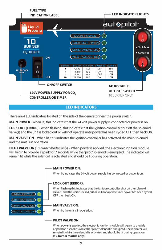
MAIN POWER ON:
When lit, indicates the 24 volt power supply has connected or power is on.
LOCK OUT (ERROR):
When flashing this indicates that the ignition controller shut off the solenoid valve(s) and the unit is locked out or will not operate until power has been cycled OFF then back ON.
MAIN VALVE ON:
When lit, the unit is in operation.
PILOT VALVE ON:
When power is applied, the electronic ignition module will begin to provide a spark for 7 seconds while the "pilot" solenoid is energized. The indicator will remain lit while the solenoid is activated and should be lit during operation. (10-burner models only)
LED INDICATORS
There are 4 LED indicators located on the side of the generator near the power switch.
MAIN POWER - When lit, this indicates that the 24 volt power supply is connected or power is on.
LOCK OUT (ERROR) - When flashing, this indicates that the ignition controller shut off the solenoid valve(s) and the unit is locked out or will not operate until power has been cycled OFF then back ON.
MAIN VALVE ON – When lit, this indicates the ignition controller has activated the main solenoid and the unit is in operation.
PILOT VALVE ON (10-burner models only) – When power is applied, the electronic ignition module will begin to provide a spark for 7 seconds while the “pilot” solenoid is energized. The indicator will remain lit while the solenoid is activated and should be lit during operation.
LED INDICATOR LIGHTSFUEL TYPE INDICATION LABEL
ON/OFF SWITCH ADJUSTABLE OUTPUT SWITCH10 BURNER ONLY
120V POWER SUPPLY FOR CO2 CONTROLLER OR TIMER
9

Determine the best location for the generator. It must be hung level in an area that is adequately ventilated. The generator needs at least 20" of clearance on all sides.
WARNING!! In closed spaces without adequate ventilation, CO2 levels can accumulate and become toxic (CO2 levels above 5000 ppm are toxic). Plants benefit from levels up to 1500 ppm. Levels above 2500 ppm can cause headaches and/or other feelings of being ill. Installation and connection of the gas lines must be completed in compliance with local and national building codes. Consult your local authorities for detailed requirements.
Step 1: Remove the 4 wing bolts (2 on each side of the unit (Image 1)), expand the top upward and install bolts into upper hole locations.
Step 2: Tighten the bolts at the top position (Image 2).
Step 3: Install the screw hook into the overhead support. Use the included carabineers to secure the chain to the unit and the screw hook.
Step 4: Verify that the generator is hanging level. The generator has a safety feature (the tip over switch) that will turn off the burners if the unit tips over or falls down. The switch is like a pendulum and will turn off the unit if it is not level.
Step 5: Verify the gas supply and the regulator used match the type of CO2 generator you’re using
(LP or NG).
Step 6: Securely tighten the gas connection with 2 wrenches using the included gas supply hose. Connect one end to the flare fitting and the other end to the provided gas regulator. Verify the connection is secured safe.
Step 7:. Pressurize the gas line after connections are verified. Use soapy water and a spray bottle to check for leaks by spraying it onto the gas connection fittings and watching for bubbles. If bubbles appear, re-secure the connection and repeat the process.
Step 8: Use the included power supply to connect the unit to a controller or timer that will determine the amount of time and how frequently the generator will operate. Note: This power adapter requires 100-240V input power. The power supply included with the CO
2 generator has a
24V output.
Step 9: The ignition module and firing sequence are activated by the main power switch located on the side of the generator.
(Image 1)
INSTALLATION
10

(Image 2)
The V top design distributes CO2 quickly and evenly
11

The ignition module and firing sequence is activated by the main power switch located on the side of the generator. The generator has power and is in operation if the green MAIN POWER indicator light is on.
NOTE: DO NOT turn on the generator. After the unit has been successfully installed, read the Startup Procedure to ensure safe and proper use of the generator.
WARNING!! A spark is produced from a pair of electrodes near the tip of the brass burners to ignite the gas. Keep foreign objects away from electrodes.
1. After completing the installation, follow this startup procedure:2. Verify that the power switch is off and that the unit is not plugged in.3. Verify that there are no foreign objects or loose packing materials on the inside of the unit.4. Make sure nothing appears damaged or out of place.5. Check and confirm that the gas connections are connected properly.6. Pressurize the gas lines by opening any of the shut off valves on the gas supply. Test for gas
leaks, especially if this is the first time the unit will be used.7. Make sure there are no objects within 20" of the surface of the unit.8. Plug in the 24 volt DC power supply into a 120-240 volt power source, then connect the small
power cable to the power inlet jack on the CO2 generator.9. Turn the power switch ON. The MAIN POWER green LED indicator light should illuminate.10. Shortly afterward, the ignition module will attempt to ignite the burner(s) for approximately
7 seconds. On 4-burner and 8-burner models, the MAIN VALVE ON light will indicate this by illuminating. On the 10-burner models, both the MAIN VALVE ON and the yellow PILOT VALVE ON LED indicator lights will illuminate.
11. If the flames last less then 5 seconds, generator will pause for 3 seconds, and start to attempt to re-ignite again. This cycle repeats a maximum of 5 times. If the flames still can’t last more than 5 seconds, the unit will be locked out. The LED “lock out error” will be on the control panel. To re-ignite the unit reset the power to remove the error and try again. Turn off the unit and wait for five minutes before attempting to re-ignite.
12. Self check function: After a continuous burn of 1 hour, the unit will perform a 5 second self check. If no problem after self-check, then it will re-start again automatically.
NOTE: If starting the unit for the first time or after a new tank is connected, make sure to “purge” the gas line of any air to ensure gas is flowing to the burners. Once the burners fire, look under the unit and confirm the flame is blue and consistent.
WARNING!! Power the unit off immediately if the flame appears yellow or excessively large. DO NOT OPERATE with yellow, excessively large, or small “lazy” blue flames.
• If the flame appears yellow or too large, verify that the correct gas supply is being used and that the supplied gas regulator is being used. High pressure or incorrect gas type may increase flames to dangerous heights.
• If the flame is blue but appears small, verify that the correct gas supply is being used (if LP, verify tank level is not low) and that the supplied gas regulator is being used. Low pressure or low LP tank may cause small or “lazy” blue flames.
• After the generator has been tested at full capacity, connect the generator to a compatible controller or timer.
WARNING!! The generator produces up to 22,000 BTU of heat at full capacity. Verify that the area around the generator is not getting too hot.
STARTUP PROCEDURE
12

The generator requires unrestricted airflow through the bottom and must be hung. DO NOT set the generator on top of anything such as a table, stand, etc.
Select an overhead support such as a ceiling joist from which to hang the generator. The unit must have a 20" minimum space between the unit and wall, roof or any other possible obstruction.
• Use the provided hardware (20" chains, screw hooks, and carabiners) to securely hang the generator.
• Read all instructions before operating your Autopilot CO2 Generator
• Do not put your CO2 generator in an area where it can get wet or sprayed
• Mount your CO2 generator SECURELY to the ceiling using hardware provided
• Make sure there are no objects within 20” from the unit’s operating position• LP/NG gases can be dangerous – check all connections with soapy water before firing• If you smell gas, unplug CO
2 generator and do NOT re-light until connections are tightened
• When using “bug sprays” in area, cover generator completely to avoid corrosion• Do not attempt to repair the unit or this will void the warranty• Make sure to verify your power source prior to plugging CO
2 generator into outlet
• Check that all equipment that will activate this CO2 generator is the proper voltage
• Avoid touching or handling CO2 generator chassis while in use. You may get burned!
• Use caution when operating CO2 generator in extremely humid environments
• Operate CO2 generator in well-ventilated area
• Do NOT use Teflon tape on gas connections. All gas fittings are self-sealing• Do not use CO
2 generator for purposes other than the unit was designed to function
• Use CO2 generator within defined environmental specifications
• Ask your dealer for tips and techniques regarding the use of this CO2 generator
We recommend operating the CO2 generator with our Autopilot CO2 Controllers
(Image 3)
ADDITIONAL TIPS
13
Should there be a gas odor in the area?
NO. Turn off the gas supply immediately. Do not turn on any electrical devices. Ventilate the area by opening vents, doors, or windows. Leave the area until the gas odor is no longer present. Once ventilated and the gas odor is gone, determine where the leak is by using soapy water. Spray the soapy solution on the gas connections and watch for bubbles. Bubbles will appear if the connection(s) are leaking. Seal the leaks. If this does not correct the problem, call the manufacturer. Refer also to the WHAT TO DO IF YOU SMELL GAS section on the facing page.
The power is connected but not working and no indicator light is on. What's wrong?
The “tilt” switch may be activated. Tilt the unit to one side and listen for a clicking noise. The switch is like a pendulum and will turn off the unit if it is not level.
The burners are not lighting but the unit is trying. What's wrong?
If the burners do not fire the first attempt, it will try again. After a 30 second pause the unit will attempt to re-fire the burner(s) for 15 seconds, This cycle will repeat until it fires or a maximum of 5 times. After 5 unsuccessful attempts, the module will lock itself for a 20 minute pause. The LED light next to LOCK OUT (ERROR) will be illuminated. Verify that the spark is being generated and the position of the sparking electrodes is close to the burner to be lit.
One or more of the burners is not lighting. What's wrong?
Make sure the gas line is not kinked or twisted and the gas supply is adequate. Do not operate if yellow or large flames are present. If using propane, turn off the gas regulator for 30 seconds, and then try again.
The CO2 level is not increasing to my desired PPM level. Why not?
If both burners are operating, check for air leakage in the grow area and confirm that exhaust fans are not operating when the CO2 is being produced.
Should the generator be buzzing and/or sparking?
Yes, when the unit is firing you will hear “sparking” sounds. It will attempt this up to 5 times, before going into lock out mode. However it is not usual for the unit not to start after 5 times unless the gas flow has been interrupted.
The indicator light beside the “LOCK OUT (ERROR)” is flashing. What does that mean?
The unit may be out of propane or the gas supply may have been interrupted. The safety mode or Lock Out (error) is an automatic built-in feature that will activate if the pilot does not fire after 5 attempts. Once the problem has been corrected, turning the power off for 30 seconds and back on will reset this function. It will also reset after 20 minutes and attempt to ignite the burners.
How should the flame(s) appear?
The flames should burn clean and blue with a resemblance to a flower or 6-point star. If the flame is yellow, extra large or a small blue dot not resembling a flower or 6-point star, DO NOT OPERATE THE GENERATOR. Consult the manufacturer.
Does it matter which burner I remove?
Yes, the two burners on the right located directly under the ignitor must remain in place.
How much CO2 does the unit produce?
The brass burners are designed to produce approximately 3 cu ft per hr. If more CO2 production is required, add an additional generator.
Q & A
14

NOTE: At the time of installation of this generator, a small amount of gas will be released and its odor will be noticed. This is normal, and the odor should dissipate after a few minutes. However, if you detect the odor of LP/NG at any other time after installation, you might have a leak and should follow these instructions:
• Do not try to light the appliance or use any form of open flame.• Do not touch any electrical switch, use a cell phone, or touch anything that uses electricity in
the room or building.• Open doors or windows to ventilate the area.• Close the shutoff valve on your interior tank, exterior tank, or your main residential exterior
shutoff valve if using a municipal NG supply.• If your gas supply comes from a public gas utility, you may need to place an emergency call to
them so that they can examine the gas connections.
WARNING!! If the information in this manual is not followed exactly, a fire or explosion could result, causing property damage, personal injury or loss of life.
• Do not store or use gasoline or other flammable vapors and liquids in the vicinity of this or any other appliance.
• Installation and service must be performed by a qualified installer, service agency or the gas supplier.
WHAT TO DO IF YOU SMELL GAS
ELECTRONIC IGNITION CONTROL MODULE
For safer operation, the generator has an Electronic Ignition Control Module that eliminates the need for an “open” pilot flame. The module creates a spark that lights the burner(s), providing consistent and controlled starts.
15

Hydrofarm.com
LIMITED WARRANTY
Hydrofarm warrants the Autopilot CO2 Generator to be free from defects in materials and workmanship. The warranty term is for 3 years beginning on the date of purchase. Misuse, abuse, or failure to follow instructions is not covered under this warranty. Hydrofarm’s warranty liability extends only to the replacement cost of the product. Hydrofarm will not be liable for any consequential, indirect, or incidental damages of any kind, including lost revenues, lost profits, or other losses in connection with the product. Some states do not allow limitation on how long an implied warranty lasts or the exclusion of incidental or consequential damages, so the above limitations or exclusions may not apply to you. Hydrofarm will, at our discretion, repair or replace the Autopilot CO2 Generator covered under this warranty if it is returned to the original place of purchase. To request warranty service, please return the Autopilot CO2 Generator, with original sales receipt and original packaging, to your place of purchase. The purchase date is based on your original sales receipt.
Autopilot CO2 Generator Instructions revised - March 6, 2017 9:16 AM
WA R R A N T Y
Like us on Facebook, follow us on Twitter, and check out Hydrofarmtv on YouTube and Instagram!
Get Connected with the Hydrofarm Community:
precise climate controlprecise climate control


![Second Revision No. 37-NFPA 1964-2017 [ Detail ] Submitter ......Pump discharge pressure from 500 psi (3500 kPa) to less than 1100 psi (7600 kPa). [1901, 2016] 3.3.14.2*Normal Pressure](https://img.pdfslide.us/doc/110x75/5e95fc37866b3a78665336b5/second-revision-no-37-nfpa-1964-2017-detail-submitter-pump-discharge.jpg)