Embed Size (px)
Citation preview

KRAMER ELECTRONICS LTD.
USER MANUAL
MODEL:
PSE-1 10G POE Injector
P/N: 2900-300438 Rev 1
PSE-1 – Contents i
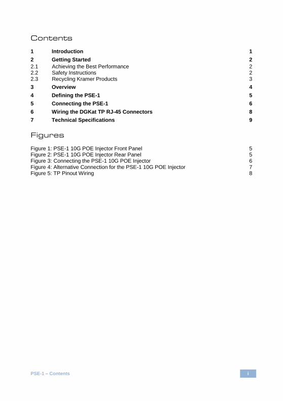
Contents
1 Introduction 1 2 Getting Started 2 2.1 Achieving the Best Performance 2 2.2 Safety Instructions 2 2.3 Recycling Kramer Products 3 3 Overview 4 4 Defining the PSE-1 5 5 Connecting the PSE-1 6 6 Wiring the DGKat TP RJ-45 Connectors 8 7 Technical Specifications 9
Figures
Figure 1: PSE-1 10G POE Injector Front Panel 5 Figure 2: PSE-1 10G POE Injector Rear Panel 5 Figure 3: Connecting the PSE-1 10G POE Injector 6 Figure 4: Alternative Connection for the PSE-1 10G POE Injector 7 Figure 5: TP Pinout Wiring 8

PSE-1 - Introduction 1
1 Introduction
Welcome to Kramer Electronics! Since 1981, Kramer Electronics has been
providing a world of unique, creative, and affordable solutions to the vast range of
problems that confront the video, audio, presentation, and broadcasting
professional on a daily basis. In recent years, we have redesigned and upgraded
most of our line, making the best even better!
Our 1,000-plus different models now appear in 14 groups that are clearly defined
by function: GROUP 1: Distribution Amplifiers; GROUP 2: Switchers and Routers;
GROUP 3: Control Systems; GROUP 4: Format/Standards Converters; GROUP 5:
Range Extenders and Repeaters; GROUP 6: Specialty AV Products; GROUP 7:
Scan Converters and Scalers; GROUP 8: Cables and Connectors; GROUP 9:
Room Connectivity; GROUP 10: Accessories and Rack Adapters and GROUP 11:
Sierra Products; GROUP 12: Digital Signage; and GROUP 13: Audio, and
GROUP 14: Collaboration.
Congratulations on purchasing your Kramer PSE-1 10G POE Injector, which is
ideal for the following typical applications:
Home theater, presentation and multimedia applications
Boardrooms and classrooms
2 PSE-1 - Getting Started
2 Getting Started
We recommend that you:
Unpack the equipment carefully and save the original box and packaging
materials for possible future shipment
Review the contents of this user manual
Go to http://www.kramerelectronics.com/support/product_downloads.asp
to check for up-to-date user manuals, application programs, and to check
if firmware upgrades are available (where appropriate).
2.1 Achieving the Best Performance
To achieve the best performance:
Use only good quality connection cables (we recommend Kramer high-
performance, high-resolution cable) to avoid interference, deterioration in
signal quality due to poor matching, and elevated noise levels (often
associated with low quality cables)
Do not secure the cables in tight bundles or roll the slack into tight coils
Avoid interference from neighboring electrical appliances that may adversely
influence signal quality
Position your Kramer PSE-1 away from moisture, excessive sunlight and
dust
This equipment is to be used only inside a building. It may only be
connected to other equipment that is installed inside a building.
2.2 Safety Instructions
Caution: No operator serviceable parts inside the unit
Warning: Use only the Kramer Electronics input power wall adapter
that is provided with the unit
Warning: Disconnect the power and unplug the unit from the wall
before installing
i
!
!

PSE-1 - Getting Started 3
2.3 Recycling Kramer Products
The Waste Electrical and Electronic Equipment (WEEE) Directive 2002/96/EC
aims to reduce the amount of WEEE sent for disposal to landfill or incineration by
requiring it to be collected and recycled. To comply with the WEEE Directive,
Kramer Electronics has made arrangements with the European Advanced
Recycling Network (EARN) and will cover any costs of treatment, recycling and
recovery of waste Kramer Electronics branded equipment on arrival at the EARN
facility. For details of Kramer’s recycling arrangements in your particular country
go to our recycling pages at http://www.kramerelectronics.com/support/recycling/.
4 PSE-1 - Overview
3 Overview
The PSE-1 is a PoE (Power-over-Ethernet) injector.
The PSE-1 provides power remotely over Ethernet to any device capable of acting
as a PoE acceptor, (for example, a wallplate, where it may be difficult to connect
an external power supply). This allows a single HDBT LAN cable to provide both
data and electrical power to compatible devices.
In particular, the PSE-1 features:
A total range of up to 100m (328ft) @ 4K on shielded BC-DGKat623 cable
(or equivalent)
4K support
48V DC power
A Kramer DigiTOOLS ® enclosure
PSE-1 - Defining the PSE-1 5
4 Defining the PSE-1
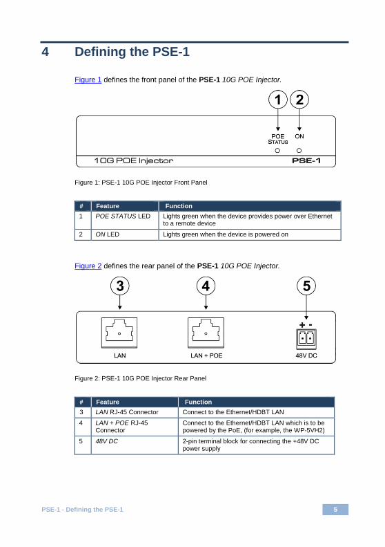
Figure 1 defines the front panel of the PSE-1 10G POE Injector.
Figure 1: PSE-1 10G POE Injector Front Panel
# Feature Function
1 POE STATUS LED Lights green when the device provides power over Ethernet to a remote device
2 ON LED Lights green when the device is powered on
Figure 2 defines the rear panel of the PSE-1 10G POE Injector.
Figure 2: PSE-1 10G POE Injector Rear Panel
# Feature Function
3 LAN RJ-45 Connector Connect to the Ethernet/HDBT LAN
4 LAN + POE RJ-45 Connector
Connect to the Ethernet/HDBT LAN which is to be powered by the PoE, (for example, the WP-5VH2)
5 48V DC 2-pin terminal block for connecting the +48V DC power supply
6 PSE-1 - Connecting the PSE-1
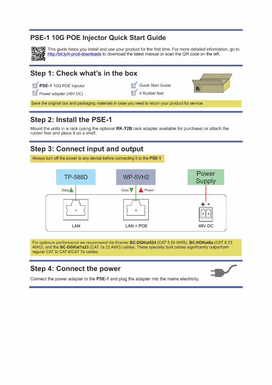
5 Connecting the PSE-1
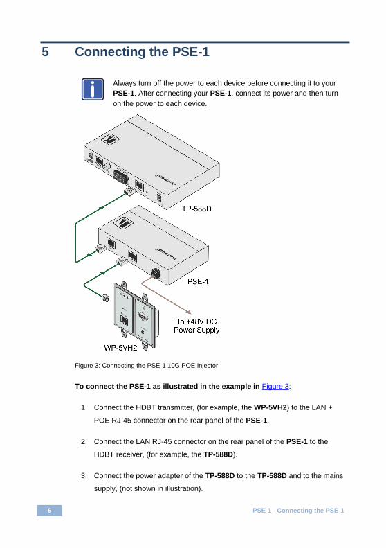
Always turn off the power to each device before connecting it to your
PSE-1. After connecting your PSE-1, connect its power and then turn
on the power to each device.
Figure 3: Connecting the PSE-1 10G POE Injector
To connect the PSE-1 as illustrated in the example in Figure 3:
1. Connect the HDBT transmitter, (for example, the WP-5VH2) to the LAN +
POE RJ-45 connector on the rear panel of the PSE-1.
2. Connect the LAN RJ-45 connector on the rear panel of the PSE-1 to the
HDBT receiver, (for example, the TP-588D).
3. Connect the power adapter of the TP-588D to the TP-588D and to the mains
supply, (not shown in illustration).
i
PSE-1 - Connecting the PSE-1 7
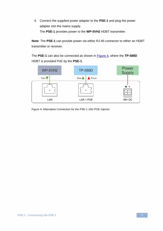
4. Connect the supplied power adapter to the PSE-1 and plug the power
adapter into the mains supply.
The PSE-1 provides power to the WP-5VH2 HDBT transmitter.
Note: The PSE-1 can provide power via either RJ-45 connector to either an HDBT
transmitter or receiver.
The PSE-1 can also be connected as shown in Figure 4, where the TP-588D
HDBT is provided PoE by the PSE-1.
Figure 4: Alternative Connection for the PSE-1 10G POE Injector
8 PSE-1 - Wiring the DGKat TP RJ-45 Connectors
6 Wiring the DGKat TP RJ-45 Connectors
Connect/solder the cable shield to the RJ-45 connector shield at both ends of the
cable.
Do not use a crossed TP cable with this product.
Using a TP cable that is incorrectly wired may cause permanent
damage to the device
Do not use unshielded TP cables with this product
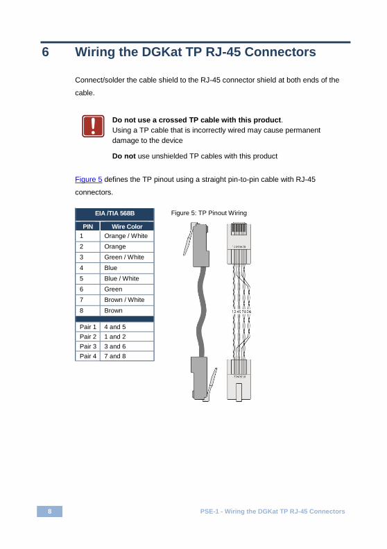
Figure 5 defines the TP pinout using a straight pin-to-pin cable with RJ-45
connectors.
EIA /TIA 568B Figure 5: TP Pinout Wiring
PIN Wire Color
1 Orange / White
2 Orange
3 Green / White
4 Blue
5 Blue / White
6 Green
7 Brown / White
8 Brown
Pair 1 4 and 5
Pair 2 1 and 2
Pair 3 3 and 6
Pair 4 7 and 8
!
PSE-1 - Technical Specifications 9
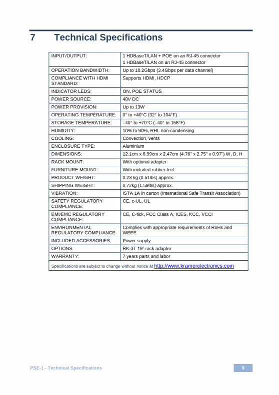
7 Technical Specifications
INPUT/OUTPUT: 1 HDBaseT/LAN + POE on an RJ-45 connector
1 HDBaseT/LAN on an RJ-45 connector
OPERATION BANDWIDTH: Up to 10.2Gbps (3.4Gbps per data channel)
COMPLIANCE WITH HDMI STANDARD:
Supports HDMI, HDCP
INDICATOR LEDS: ON, POE STATUS
POWER SOURCE: 48V DC
POWER PROVISION: Up to 13W
OPERATING TEMPERATURE: 0° to +40°C (32° to 104°F)
STORAGE TEMPERATURE: –40° to +70°C (–40° to 158°F)
HUMIDITY: 10% to 90%, RHL non-condensing
COOLING: Convection, vents
ENCLOSURE TYPE: Aluminium
DIMENSIONS: 12.1cm x 6.99cm x 2.47cm (4.76" x 2.75" x 0.97") W, D, H
RACK MOUNT: With optional adapter
FURNITURE MOUNT: With included rubber feet
PRODUCT WEIGHT: 0.23 kg (0.51lbs) approx.
SHIPPING WEIGHT: 0.72kg (1.59lbs) approx.
VIBRATION: ISTA 1A in carton (International Safe Transit Association)
SAFETY REGULATORY COMPLIANCE:
CE, c-UL, UL
EMI/EMC REGULATORY COMPLIANCE:
CE, C-tick, FCC Class A, ICES, KCC, VCCI
ENVIRONMENTAL REGULATORY COMPLIANCE:
Complies with appropriate requirements of RoHs and WEEE
INCLUDED ACCESSORIES: Power supply
OPTIONS: RK-3T 19” rack adapter
WARRANTY: 7 years parts and labor
Specifications are subject to change without notice at http://www.kramerelectronics.com


For the latest information on our products and a list of Kramer distributors, visit our Web site where updates to this user manual may be found.
We welcome your questions, comments, and feedback. Web site: www.kramerelectronics.com E-mail: [email protected]
SAFETY WARNING
Disconnect the unit from the powersupply before opening and servicing
P/N: 2900- 300438 Rev: 1
!